WO2012008573A1 - 超音波撮像装置 - Google Patents
超音波撮像装置 Download PDFInfo
- Publication number
- WO2012008573A1 WO2012008573A1 PCT/JP2011/066220 JP2011066220W WO2012008573A1 WO 2012008573 A1 WO2012008573 A1 WO 2012008573A1 JP 2011066220 W JP2011066220 W JP 2011066220W WO 2012008573 A1 WO2012008573 A1 WO 2012008573A1
- Authority
- WO
- WIPO (PCT)
- Prior art keywords
- imaging apparatus
- ultrasonic imaging
- filter
- signal
- ultrasonic
- Prior art date
- Legal status (The legal status is an assumption and is not a legal conclusion. Google has not performed a legal analysis and makes no representation as to the accuracy of the status listed.)
- Ceased
Links
Images





Classifications
-
- A—HUMAN NECESSITIES
- A61—MEDICAL OR VETERINARY SCIENCE; HYGIENE
- A61B—DIAGNOSIS; SURGERY; IDENTIFICATION
- A61B8/00—Diagnosis using ultrasonic, sonic or infrasonic waves
- A61B8/13—Tomography
- A61B8/14—Echo-tomography
- A61B8/145—Echo-tomography characterised by scanning multiple planes
-
- A—HUMAN NECESSITIES
- A61—MEDICAL OR VETERINARY SCIENCE; HYGIENE
- A61B—DIAGNOSIS; SURGERY; IDENTIFICATION
- A61B8/00—Diagnosis using ultrasonic, sonic or infrasonic waves
- A61B8/52—Devices using data or image processing specially adapted for diagnosis using ultrasonic, sonic or infrasonic waves
- A61B8/5269—Devices using data or image processing specially adapted for diagnosis using ultrasonic, sonic or infrasonic waves involving detection or reduction of artifacts
-
- A—HUMAN NECESSITIES
- A61—MEDICAL OR VETERINARY SCIENCE; HYGIENE
- A61B—DIAGNOSIS; SURGERY; IDENTIFICATION
- A61B8/00—Diagnosis using ultrasonic, sonic or infrasonic waves
- A61B8/46—Ultrasonic, sonic or infrasonic diagnostic devices with special arrangements for interfacing with the operator or the patient
- A61B8/461—Displaying means of special interest
-
- A—HUMAN NECESSITIES
- A61—MEDICAL OR VETERINARY SCIENCE; HYGIENE
- A61B—DIAGNOSIS; SURGERY; IDENTIFICATION
- A61B8/00—Diagnosis using ultrasonic, sonic or infrasonic waves
- A61B8/54—Control of the diagnostic device
-
- G—PHYSICS
- G01—MEASURING; TESTING
- G01S—RADIO DIRECTION-FINDING; RADIO NAVIGATION; DETERMINING DISTANCE OR VELOCITY BY USE OF RADIO WAVES; LOCATING OR PRESENCE-DETECTING BY USE OF THE REFLECTION OR RERADIATION OF RADIO WAVES; ANALOGOUS ARRANGEMENTS USING OTHER WAVES
- G01S7/00—Details of systems according to groups G01S13/00, G01S15/00, G01S17/00
- G01S7/52—Details of systems according to groups G01S13/00, G01S15/00, G01S17/00 of systems according to group G01S15/00
- G01S7/52017—Details of systems according to groups G01S13/00, G01S15/00, G01S17/00 of systems according to group G01S15/00 particularly adapted to short-range imaging
- G01S7/52046—Techniques for image enhancement involving transmitter or receiver
-
- G—PHYSICS
- G01—MEASURING; TESTING
- G01S—RADIO DIRECTION-FINDING; RADIO NAVIGATION; DETERMINING DISTANCE OR VELOCITY BY USE OF RADIO WAVES; LOCATING OR PRESENCE-DETECTING BY USE OF THE REFLECTION OR RERADIATION OF RADIO WAVES; ANALOGOUS ARRANGEMENTS USING OTHER WAVES
- G01S7/00—Details of systems according to groups G01S13/00, G01S15/00, G01S17/00
- G01S7/52—Details of systems according to groups G01S13/00, G01S15/00, G01S17/00 of systems according to group G01S15/00
- G01S7/52017—Details of systems according to groups G01S13/00, G01S15/00, G01S17/00 of systems according to group G01S15/00 particularly adapted to short-range imaging
- G01S7/52077—Details of systems according to groups G01S13/00, G01S15/00, G01S17/00 of systems according to group G01S15/00 particularly adapted to short-range imaging with means for elimination of unwanted signals, e.g. noise or interference
-
- A—HUMAN NECESSITIES
- A61—MEDICAL OR VETERINARY SCIENCE; HYGIENE
- A61B—DIAGNOSIS; SURGERY; IDENTIFICATION
- A61B8/00—Diagnosis using ultrasonic, sonic or infrasonic waves
- A61B8/06—Measuring blood flow
-
- A—HUMAN NECESSITIES
- A61—MEDICAL OR VETERINARY SCIENCE; HYGIENE
- A61B—DIAGNOSIS; SURGERY; IDENTIFICATION
- A61B8/00—Diagnosis using ultrasonic, sonic or infrasonic waves
- A61B8/48—Diagnostic techniques
- A61B8/488—Diagnostic techniques involving Doppler signals
-
- A—HUMAN NECESSITIES
- A61—MEDICAL OR VETERINARY SCIENCE; HYGIENE
- A61B—DIAGNOSIS; SURGERY; IDENTIFICATION
- A61B8/00—Diagnosis using ultrasonic, sonic or infrasonic waves
- A61B8/52—Devices using data or image processing specially adapted for diagnosis using ultrasonic, sonic or infrasonic waves
- A61B8/5207—Devices using data or image processing specially adapted for diagnosis using ultrasonic, sonic or infrasonic waves involving processing of raw data to produce diagnostic data, e.g. for generating an image
-
- G—PHYSICS
- G01—MEASURING; TESTING
- G01S—RADIO DIRECTION-FINDING; RADIO NAVIGATION; DETERMINING DISTANCE OR VELOCITY BY USE OF RADIO WAVES; LOCATING OR PRESENCE-DETECTING BY USE OF THE REFLECTION OR RERADIATION OF RADIO WAVES; ANALOGOUS ARRANGEMENTS USING OTHER WAVES
- G01S15/00—Systems using the reflection or reradiation of acoustic waves, e.g. sonar systems
- G01S15/88—Sonar systems specially adapted for specific applications
- G01S15/89—Sonar systems specially adapted for specific applications for mapping or imaging
- G01S15/8906—Short-range imaging systems; Acoustic microscope systems using pulse-echo techniques
- G01S15/8959—Short-range imaging systems; Acoustic microscope systems using pulse-echo techniques using coded signals for correlation purposes
- G01S15/8961—Short-range imaging systems; Acoustic microscope systems using pulse-echo techniques using coded signals for correlation purposes using pulse compression
-
- G—PHYSICS
- G01—MEASURING; TESTING
- G01S—RADIO DIRECTION-FINDING; RADIO NAVIGATION; DETERMINING DISTANCE OR VELOCITY BY USE OF RADIO WAVES; LOCATING OR PRESENCE-DETECTING BY USE OF THE REFLECTION OR RERADIATION OF RADIO WAVES; ANALOGOUS ARRANGEMENTS USING OTHER WAVES
- G01S15/00—Systems using the reflection or reradiation of acoustic waves, e.g. sonar systems
- G01S15/88—Sonar systems specially adapted for specific applications
- G01S15/89—Sonar systems specially adapted for specific applications for mapping or imaging
- G01S15/8906—Short-range imaging systems; Acoustic microscope systems using pulse-echo techniques
- G01S15/8979—Combined Doppler and pulse-echo imaging systems
Definitions
- the present invention relates to a medical ultrasonic imaging apparatus, and more particularly to a technology for improving image quality by improving a signal-to-noise ratio.
- Ultrasonic diagnostic apparatuses are widely used as medical tomographic imaging apparatuses because of their real-time characteristics and portable characteristics.
- Indispensable as a medical diagnostic imaging device as a technique for detecting lesions such as tumors in soft tissues such as body surface tissues such as the mammary gland and thyroid gland, digestive organs such as the liver and kidneys, and circulatory organs such as the heart and vessels It has become.
- the attenuation rate associated with the propagation of ultrasonic waves in the living body increases as the frequency increases. That is, the higher the frequency, the more significant the signal intensity is attenuated far from the ultrasound probe. Since ultrasonic energy attenuated in the living body is converted into heat, applying excessive ultrasonic sound pressure may pose a risk of damaging the living body. Further, when the instantaneous sound pressure increases, the risk of cavitation may increase. In order to minimize the risk of such biological damage, there is a limit to the sound pressure and energy of ultrasonic waves that can be transmitted to the living body. There is no way to recover.
- the A / D conversion In a normal diagnostic apparatus, since the A / D conversion is performed after the echo signal is received and amplified by the preamplifier, the A / D conversion always has a finite dynamic range because of the finite bit width. Furthermore, the actual situation is that the dynamic range of A / D conversion cannot be fully used under the influence of random electrical noise after A / D conversion. For this reason, when the echo from the deep part of the living body is lowered due to the attenuation of the living body, the signal-to-noise ratio is lowered, and the sensitivity and resolution of the image are lowered. In order to compensate for this, there is a problem that if the frequency is lowered, the spatial resolution is lowered.
- the band pass filter on the frequency axis is one method that contributes to both spatial resolution and imaging field of view (penetration).
- penetration in order to greatly improve the signal-to-noise ratio by this method, it is necessary to narrow the bandwidth of the bandpass filter, which may lead to a reduction in spatial resolution. In the end, this does not escape the trade-off between spatial resolution and imaging field of view.
- An object of the present invention is to achieve both spatial resolution and imaging field of view of an ultrasonic diagnostic apparatus by another means.
- an ultrasonic transducer a transmission unit that transmits ultrasonic waves to the subject via the ultrasonic transducer, and a received wave received from the subject by the ultrasonic transducer
- An ultrasonic diagnostic apparatus having a receiving unit for phasing a signal, a display unit for displaying a tomographic image of a subject from a received signal output from the receiving unit, and a control unit for controlling the transmitting unit and the receiving unit
- the reception unit includes an interchannel filter that selectively suppresses electrical noise, a reception beamformer that selectively receives a beam, and an envelope detection unit.
- the interchannel filter is an echo signal from a subject.
- the ultrasonic diagnostic apparatus is configured to perform a filtering process for separating the signal and the noise included in the signal according to the continuity between the channels and removing the noise. That is, in the present invention, after the A / D conversion, the signal-to-noise ratio is improved by suppressing the reduction in spatial resolution as much as possible by performing filtering between channels or two-dimensional filtering between channels and the time axis. Plan.
- the two basic performances of the ultrasonic diagnostic apparatus ie, the spatial resolution and the signal-to-noise ratio are balanced, and as a result, the image quality of the tomographic image is improved.
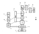
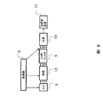
- FIG. 1 is a block diagram showing a device configuration of an ultrasonic imaging apparatus according to an embodiment of the present invention.
- the block diagram which shows the apparatus structure of the ultrasonic imaging device of conventional embodiment.
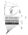
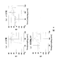
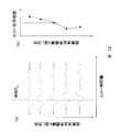
- Explanatory drawing of the concept of this invention Results of calculating the signal-to-noise intensity ratio based on the presence or absence of electrical noise, and the signal-to-noise intensity ratio when the conventional method is applied. The result of having calculated the intensity ratio of a signal and noise by the method of the present invention.
- Explanatory drawing of the simulation model for examining this invention Explanatory drawing regarding the characteristic of an electrical noise and an acoustic signal.
- the block diagram which shows a part of apparatus structure of the ultrasonic imaging device of embodiment of this invention Illustration of the filtering algorithm of the present invention Illustration of the signal processing algorithm of the present invention Device configuration diagram when the present invention is applied to a Doppler blood flow image Conceptual diagram of Doppler signal processing Illustration of noise targeted by the present invention in Doppler signal processing
- Example 1 relates to an ultrasonic diagnostic apparatus, and includes an ultrasonic transducer 1, a transmission unit that transmits ultrasonic waves to the subject via the ultrasonic transducer, and a received wave that the ultrasonic transducer receives from the subject.
- Ultrasound diagnosis having a receiving unit for phasing a signal, a display unit 14 for displaying a tomographic image of a subject from a received signal output from the receiving unit, and a control unit 6 for controlling the transmitting unit and the receiving unit
- the reception unit includes an interchannel filter 9 that selectively suppresses electrical noise, a reception beamformer 10 that selectively receives a beam, and an envelope detection unit 11.
- This is an embodiment of an ultrasonic diagnostic apparatus that performs a filtering process for separating a signal and noise included in an echo signal from a specimen by continuity between channels and removing the noise.
- an ultrasonic transducer 1 installed on the surface of a subject is transmitted from a transmission beam former (BF) 4 via a transmission / reception changeover switch (SW) 2 under the control of a control unit 6.
- the waveform transmission stored in the transmission memory 5 is transmitted as an electric pulse through the wave amplifier 3.
- the transmission amplifier 3, the transmission beam former 4, and the waveform memory 5 constitute a transmission unit.
- the transmission beamformer 4 is controlled so that the delay time between each channel (hereinafter sometimes abbreviated as “ch”) of the transducer 1 is suitable so that the ultrasonic beam travels on a desired scanning line. is doing.
- the ultrasound transducer 1 converts the electrical signal into an ultrasound signal, and an ultrasound pulse is transmitted into the subject.
- a part of the scattered ultrasonic pulse is received as an echo signal again by the ultrasonic transducer 1 and converted from the ultrasonic signal to an electric signal.
- the received signal is taken into the receiving unit via the transmission / reception selector switch 2.
- the echo propagation distance is first set by the time gain control (TGC) amplifier 7.
- the analog signal is converted from an analog signal to a digital signal by an analog / digital (A / D) conversion element 8 and the signal-to-noise ratio is improved by an interchannel filter 9 which is a feature of the present invention.
- the beamformer (BF) 10 performs phasing addition as data on a certain scanning line in which an echo signal from a desired depth on the desired scanning line is selectively enhanced. This phased and added data is converted into an envelope signal by the envelope detector 11 and sent to the scan converter 13 via the band pass filter 12 to perform scan conversion. The data after the scan conversion is sent to the display unit 14 and displayed as an ultrasonic tomographic image.
- the receiving unit of the ultrasonic diagnostic apparatus of the present embodiment includes at least an interchannel filter 9 that selectively suppresses electrical noise, a receiving beamformer 10 that selectively receives a beam, and an envelope detector 11.
- FIG. The apparatus configuration is the same as that of the present invention except that there is no interchannel filter 9 after the A / D conversion element 8.
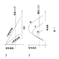
- FIG. 7 shows a schematic diagram of electrical signal and acoustic signal characteristics for each frequency.
- the vertical axis represents the noise intensity of the signal (each component for the signal)
- the horizontal axis in (a) represents the depth (signal propagation distance)
- the horizontal axis in (b) represents the frequency.
- the noise it is almost flat regardless of the depth (corresponding to the echo reception time) and the frequency.
- the signal intensity decreases with depth, and the slope increases as the frequency increases.
- the frequency at which the necessary signal-to-noise ratio can be obtained at the deepest point in the imaging field is the lower limit frequency in the imaging conditions, and this varies depending on the measurement site and disease. It may also be adjusted according to user preferences. Since a high spatial resolution can be realized by using a high frequency, the highest frequency is used as the upper limit frequency in the frequency at which the required signal-to-noise ratio can be obtained in the shallowest part of the imaging field. The upper limit frequency also varies depending on the measurement site and the disease, and may be adjusted according to user preferences.
- the echo signal returned from the scatterer in the body is converted into an electrical signal with a time difference corresponding to the distance with respect to the adjacent transducer. That is, the signal resulting from the echo signal has a certain continuity between channels.
- the electrical noise mixed after being converted into an electrical signal by the vibrator is random between the channels in the case of white noise, so there is no continuity between the channels.
- the signal and noise included in the echo signal are separated by the continuity between the channels, and the noise is removed.
- the rightmost signal in FIG. 3 schematically shows the signal intensity distribution in the ch direction at a certain time.
- the acoustic signal has continuity, and the electric noise appears as a signal without continuity. Therefore, filtering between channels is performed before phasing addition to separate and remove electrical noise from the signal. In the process for the output of the beamformer as performed by an ordinary diagnostic apparatus, it is impossible in principle to investigate the difference in continuity focused in the present invention by the phasing addition process.
- each element receives an echo signal from a random scatterer, convolves with the transfer function of the transducer, and converts it to a waveform on the time axis.
- the scatterer space is treated as being in the focal region of the transmitted beam.
- FIG. 6 shows the scatterer distribution (a) in the actual simulation, the scatterer position correction (b) according to the propagation distance, the received echo (c), and the signal distribution after mixing noise (d). A filter was added to the signal distribution shown in (d), phasing addition was performed, and the signal-to-noise ratio was evaluated.
- (A) in FIG. 4 is echo data on the time axis after phasing addition when no noise is mixed.
- a region where the sampling point is 60 or less is a portion where there is no signal, and a region where the sampling point is 70 or more is a portion where there is a signal.
- the signal-to-noise ratio was evaluated by subtracting the average noise intensity from the average signal intensity.
- (B) is the case where there is noise, and the signal-to-noise ratio in this case was 28 dB.
- (C) is a result of applying a low-pass filter on the time axis, which is a conventional method, for each channel, and the signal-to-noise ratio was 27 dB, that is, hardly improved.
- FIG. 5 shows the result of applying the present invention.
- A is the same as (b) of FIG. 4, and is a case where a filter is not used.
- B) and (d) are the results of the present invention, and
- (c) is the result of performing noise separation and removal in the time axis direction as an object.
- a [3 ⁇ 1] median filter was used for noise removal.
- the median filter is a filter that outputs a median value among input values. This filter is effective for removing noise that takes a specific value with respect to surrounding data.
- the signal-to-noise ratio is 56 dB
- the signal-to-noise ratio is 44 dB
- the 2D median of (d) As a result of filtering, the signal-to-noise ratio was 82 dB.
- (b) of the present invention was 28 dB
- (d) was 54 dB
- the median filter on the time axis was 16 dB.
- the improvement rate of the signal-to-noise ratio according to the present invention is 54 dB at the maximum, and it has a noise suppression effect of 38 dB, that is, almost 100 times as compared with the method (c) that can be inferred from the conventional method.
- 38 dB has the effect of improving the penetration by 6 cm.
- a filter that functions adaptively to the characteristics of the signal can also be used.
- an adaptive filter with variable weight described below with reference to FIGS. 9 and 10 may be used.
- the intensity of the point where the intensity is calculated in the data input to the adaptive filter is represented as I 0, and j max is multiplied by i max by the size of the region of interest (area for calculating the weight) for calculating the output of this intensity.
- the signal intensity at the coordinates i, j in the region of interest is I ij .
- the position of the data to be calculated and the data in the range determined by i and j are set, and the weight w ij is calculated based on the weight function described later.
- the filter output I 0 ′ is obtained by Equation 1, the calculation target data is shifted, and the calculation is performed for all points in this data, the filter The process ends.
- I 0 ' ⁇ w ij ⁇ I ij / ⁇ I ij Equation 1
- ⁇ adds i and j in the range of 1 to i max and j max , respectively.
- a Gaussian function, an even-order polynomial, or the like can be used as a function whose weight decreases monotonously as the difference of I 0 -I ij increases.
- the shape of the interchannel filter (the size of the median filter in the azimuth direction and the cutoff frequency of the spatial frequency in the azimuth direction) is dynamically changed according to the depth of the echo signal source. It is effective to change to This is because, in a normal ultrasonic diagnostic apparatus, the aperture width is constant except for a very short distance. Therefore, as the depth increases, the ratio of the focal length to the aperture width increases and the beam width in the azimuth direction increases. In addition, since it shifts from a component with a high frequency due to biologically dependent attenuation, an increase in the proportion of the low-frequency component in the echo from the deep part contributes to an increase in the beam width.
- each sampling point is in focus by dynamic focusing, for example, assuming that the aperture width is W, the focal length L, the frequency f, and the sound speed v of the living body,
- the diffraction angle ⁇ can be approximated by Equation 2.
- acoustic noise a signal from the receiving focus and a signal from other positions (hereinafter referred to as acoustic noise).
- receiving beam forming there are mainly the following three signals as acoustic signals from other than the receiving focus. (1) The echo signal from the reflection source on the transmitting and receiving grating beams, (2) The echo signal from other than the receiving focus is the same as the arrival time of the echo signal from the focus as a result of refraction and scattering during propagation Acoustic noise caused by timing reception.
- Echo signals from other than the receiving focal point are received at the same timing as the arrival time of the echo signal from the focal point as a result of multiple reflections between the ultrasound probe and the reflector in the living body.
- (1) is difficult to distinguish because there is a signal and coherence from the receiving focus.
- (2) and (3) the distribution of the reception time for each channel is different from the distribution of the reception time for each channel of the signal from the receiving focus. Focusing on this difference in characteristics, the application of the present invention can reduce acoustic noise caused by (2) and (3).
- the processing of the A / D conversion 8, the interchannel filter 9, and the receiving beamformer 10 is performed in this order. However, as shown in FIG.
- the delay concave surface that is, the distribution of reception time for each channel differs between the acoustic noise and the signal. Therefore, if the phasing process corresponding to the signal is performed, the continuity between the channels of the acoustic noise is reduced, and the acoustic noise is reduced by the interchannel filter 9. The component can be suppressed.
- Example 1 an example in which the electrical noise removal method is applied to an ultrasonic tomographic image has been described.
- the present invention is applied to Doppler blood flow measurement (continuous wave Doppler and pulse Doppler measurement methods) will be described.
- continuous wave Doppler The effect of continuous wave Doppler is that the azimuth direction of receiving beam acquisition is fixed, the received data is frequency-converted by FFT or other methods, and the echo signal caused by blood flow is Doppler shifted according to the blood flow velocity.
- This is a method for estimating the velocity of the echo source using.
- a band pass filter and Doppler velocity estimation are performed to form a time-varying image of the blood flow velocity.
- the processing performed between the A / D conversion and the receiving beamformer is the same.
- pulse Doppler does not perform frequency conversion in the time axis direction of echo, but performs frequency conversion in a repeated data acquisition method.
- the processing performed between the A / D conversion and the receiving beamformer is the same as that already described.
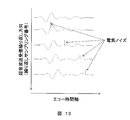
- FIG. 12 shows an example of the echo signal time axis, the ultrasonic transmission / reception repetition time axis, and the echo signal acquired by the respective repetition transmission / reception.
- the repeated transmission / reception interval is adjusted according to the movement of the object. That is, optimization is performed so that speed estimation can be performed under the restriction of the Nyquist frequency.
- a repetition frequency of about 100 Hz to 10 kHz is selected.
- the waveform in FIG. 12A does not change up and down at all, so there is no signal fluctuation in the data FIG. 12B corresponding to the specific sampling time T 0 .
- the echo waveform changes as shown in FIG. 12A, and the data corresponding to the specific sampling time T 0 in FIG. 12B.
- Phase rotation occurs in the signal. This phase rotation speed is proportional to the speed of the object in the depth direction.
- the two-dimensional median filter in the ultrasonic transmission / reception repetition direction and the ch direction shown in FIG. 12 or the three-dimensional median filter in the ultrasonic transmission / reception repetition direction, the ch direction, and the time axis of the echo is applied. Electrical noise without the above coherence can be selectively removed. The processing after removing the incoherent noise is the same as the normal pulse Doppler processing.
- the symbol with t on the right shoulder is the symbol of the transposed vector.
- a is a mode vector, which is a vector consisting of a value obtained by converting the distance difference of each channel with respect to the beam scanning direction into a phase difference.
- the incoherent noise removal of the present invention is useful as a pre-processing for the Capon beam forming. This is because the robustness of capon beamforming is improved.
- a drive encoded pulse that is longer in the time axis direction is used.
- an ultrasonic signal having an encoded waveform is transmitted from the ultrasonic probe into the living body, and is reflected by a reflector in the living body and returned.
- an encoded received waveform is obtained.
- a decoding filter corresponding to the drive encoded pulse a process for shortening the encoded waveform on the time axis by the length of the drive signal is performed.
- the present invention When the present invention is applied to coded transmission / reception, a place where an interchannel filter is inserted is important. This is because a difference in coherence between channels occurs only in the state of the encoded waveform. Therefore, in the present invention, the only solution is the order of reception A / D conversion, interchannel filter, code combination, and phasing addition.
- SYMBOLS 1 Vibrator, 2 ... Transmission / reception changeover switch, 3 ... Transmission amplifier, 4 ... Transmission beam former, 5 ... Waveform memory, 6 ... Control part, 7 ... Time gain control amplifier, 8 ... A / D conversion element, 9 ... Interchannel filter, 10 ... Received beam former, 11 ... Envelope detection, 12 ... Band pass filter, 13 ... Scan converter, 14 ... Display unit, 15 ... Phase adjusting unit, 16 ... Adder unit
Landscapes
- Health & Medical Sciences (AREA)
- Life Sciences & Earth Sciences (AREA)
- Engineering & Computer Science (AREA)
- Physics & Mathematics (AREA)
- Molecular Biology (AREA)
- General Health & Medical Sciences (AREA)
- Nuclear Medicine, Radiotherapy & Molecular Imaging (AREA)
- Pathology (AREA)
- Radiology & Medical Imaging (AREA)
- Biomedical Technology (AREA)
- Heart & Thoracic Surgery (AREA)
- Medical Informatics (AREA)
- Veterinary Medicine (AREA)
- Surgery (AREA)
- Animal Behavior & Ethology (AREA)
- Biophysics (AREA)
- Public Health (AREA)
- Computer Networks & Wireless Communication (AREA)
- General Physics & Mathematics (AREA)
- Radar, Positioning & Navigation (AREA)
- Remote Sensing (AREA)
- Computer Vision & Pattern Recognition (AREA)
- Ultra Sonic Daignosis Equipment (AREA)
- Measurement Of Velocity Or Position Using Acoustic Or Ultrasonic Waves (AREA)
- Hematology (AREA)
Abstract
Description
すなわち、本発明では、A/D変換後に、チャネル間でのフィルタリング、もしくは、チャネル間と時間軸の二次元のフィルタリングを行うことにより、空間分解能の低下を極力抑えた信号対雑音比の改善を図る。
ここで、Σはiとjをそれぞれ1からimax、jmaxの範囲で加算する。
受波焦点でのビーム幅はL×tanθでとなるので、θが小さい条件では(波長に対して十分口径が広いとき)ビーム幅はLに比例してfに反比例する。この結果、深部になるに応じて、ch間のコヒーレンス距離が、長くなるので、最適なフィルタサイズが、大きくなっていく。この変化を取り入れた方が、深さごとに最適な雑音除去を行うことが出来る。
Claims (11)
- 超音波振動子と、前記超音波振動子を介して被検体に超音波を送信する送信部と、前記超音波振動子が前記被検体から受信した受波信号を整相する受信部と、前記受信部から出力されたる受波信号から前記被検体の断層像を表示する表示部と、前記送信部と前記受信部とを制御する制御部とを有する超音波撮像装置であって、
前記受信部は電気ノイズを選択的に抑圧するチャネル間フィルタと、ビームを選択的に受信する受信ビームフォーマと、包絡線検波部を有し、前記チャネル間フィルタは被検体からのエコー信号に含まれる信号とノイズを、チャネル間の連続性により分離し、上記ノイズを除去するフィルタリング処理を行うことを特徴とする超音波撮像装置。 - 請求項1に記載の超音波撮像装置において、
前記チャネル間フィルタはA/D変換後であり、チャネル間の加算処理前であることを特徴とする超音波撮像装置。 - 請求項1に記載の超音波撮像装置において、
前記チャネル間フィルタはメディアンフィルタであることを特徴とする超音波撮像装置。 - 請求項1に記載の超音波撮像装置において、
前記チャネル間フィルタはチャネル間と時間軸の二次元メディアンフィルタであることを特徴とする超音波撮像装置。 - 請求項1に記載の超音波撮像装置において、
前記チャネル間フィルタは、前記エコーデータの各点の周辺データ点範囲を定める手段と、前記各データの信号強度と前記データ点範囲の各データ点の強度差から重み関数を決定するための関数を求める手段とを有し、前記関数は0の時に極大点をもち、負の無限大から正の無限大の範囲での前記関数の絶対値の積分値は有限であり、前記関数の微分から、前記データ点範囲の各データに対する前記重み関数を決定して、前記重み関数と前記データ点範囲の各データの強度との積和を前記データの強度に加算した値を、前記フィルタリング処理の結果の信号強度とすることを特徴とする超音波撮像装置。 - 請求項1に記載の超音波撮像装置において、
前記チャネル間フィルタのフィルタサイズが、前記エコーデータの受信時間に応じて変化するように構成されたことを特徴とする超音波撮像装置。 - 請求項1に記載の超音波撮像装置において、
前記チャネル間フィルタで分離して除去するノイズは電気ノイズとともに焦点およびその近傍にある音源以外からの音響ノイズであることを特徴とする超音波撮像装置。 - 請求項1に記載の超音波撮像装置において、
前記チャネル間フィルタはA/D変換と整相の後であり、チャネル間の加算処理前であることを特徴とする超音波撮像装置。 - 請求項1に記載の超音波撮像装置において、
特にドップラ血流測定を対象とする装置であって、前記チャネル間フィルタは超音波送受信繰り返しの時間軸と、chの並んだ軸と、エコーデータの時間軸の3つの次元のうち少なくとも二次元以上のフィルタであることを特徴とする超音波撮像装置。 - 請求項2に記載の超音波撮像装置において、
加算処理に用いる遅延データがCapon法に基づいて計算されることを特徴とする超音波撮像装置 - 請求項2に記載の超音波撮像装置において、
送波パルスを時間軸上で伸長する波形符号化回路を備え、送波波形の符号化送信を行い、前記送波波形を受波後、前記受波波形をパルス圧縮を行う複合回路を備え、前記チャネル間フィルタは、前記A/D変換の後、前記チャネル間の加算の前に行うことを特徴とする超音波撮像装置。
Priority Applications (2)
| Application Number | Priority Date | Filing Date | Title |
|---|---|---|---|
| JP2012524607A JP5514911B2 (ja) | 2010-07-15 | 2011-07-15 | 超音波撮像装置 |
| US13/808,255 US20130109968A1 (en) | 2010-07-15 | 2011-07-15 | Ultrasonic imaging device |
Applications Claiming Priority (2)
| Application Number | Priority Date | Filing Date | Title |
|---|---|---|---|
| JP2010160205 | 2010-07-15 | ||
| JP2010-160205 | 2010-07-15 |
Publications (1)
| Publication Number | Publication Date |
|---|---|
| WO2012008573A1 true WO2012008573A1 (ja) | 2012-01-19 |
Family
ID=45469567
Family Applications (1)
| Application Number | Title | Priority Date | Filing Date |
|---|---|---|---|
| PCT/JP2011/066220 Ceased WO2012008573A1 (ja) | 2010-07-15 | 2011-07-15 | 超音波撮像装置 |
Country Status (3)
| Country | Link |
|---|---|
| US (1) | US20130109968A1 (ja) |
| JP (1) | JP5514911B2 (ja) |
| WO (1) | WO2012008573A1 (ja) |
Cited By (2)
| Publication number | Priority date | Publication date | Assignee | Title |
|---|---|---|---|---|
| JP2013244205A (ja) * | 2012-05-25 | 2013-12-09 | Fujifilm Corp | 超音波診断装置およびデータ処理方法 |
| JP2016533779A (ja) * | 2013-10-07 | 2016-11-04 | アシスト・メディカル・システムズ,インコーポレイテッド | 血管内撮像の信号処理 |
Families Citing this family (14)
| Publication number | Priority date | Publication date | Assignee | Title |
|---|---|---|---|---|
| EP2488107B1 (en) | 2009-10-12 | 2017-03-08 | Acist Medical Systems, Inc. | Intravascular ultrasound system for co-registered imaging |
| US8666656B2 (en) * | 2011-03-04 | 2014-03-04 | Mitsubishi Electric Corporation | Object detection device and navigation device |
| US9693754B2 (en) | 2013-05-15 | 2017-07-04 | Acist Medical Systems, Inc. | Imaging processing systems and methods |
| JP5948527B1 (ja) * | 2014-12-22 | 2016-07-06 | オリンパス株式会社 | 超音波観測装置、超音波観測装置の作動方法および超音波観測装置の作動プログラム |
| JP6606826B2 (ja) * | 2015-01-09 | 2019-11-20 | コニカミノルタ株式会社 | 超音波診断装置 |
| US11086002B1 (en) * | 2015-04-21 | 2021-08-10 | Maxim Integrated Products, Inc. | Ultrasound sub-array receiver beamformer |
| US10909661B2 (en) | 2015-10-08 | 2021-02-02 | Acist Medical Systems, Inc. | Systems and methods to reduce near-field artifacts |
| US10653393B2 (en) | 2015-10-08 | 2020-05-19 | Acist Medical Systems, Inc. | Intravascular ultrasound imaging with frequency selective imaging methods and systems |
| US11369337B2 (en) | 2015-12-11 | 2022-06-28 | Acist Medical Systems, Inc. | Detection of disturbed blood flow |
| WO2017117389A1 (en) | 2015-12-31 | 2017-07-06 | Acist Medical Systems, Inc. | Semi-automated image segmentation system and method |
| EP3459048B1 (en) | 2016-05-16 | 2023-05-03 | Acist Medical Systems, Inc. | Motion-based image segmentation systems and methods |
| US11547389B2 (en) * | 2017-09-22 | 2023-01-10 | Philips Image Guided Therapy Corporation | Methods and systems for ultrasound contrast enhancement |
| US11024034B2 (en) | 2019-07-02 | 2021-06-01 | Acist Medical Systems, Inc. | Image segmentation confidence determination |
| JP7738402B2 (ja) * | 2021-04-05 | 2025-09-12 | キヤノンメディカルシステムズ株式会社 | 超音波診断装置、画像処理装置、およびプログラム |
Citations (8)
| Publication number | Priority date | Publication date | Assignee | Title |
|---|---|---|---|---|
| JPS61191346A (ja) * | 1985-02-19 | 1986-08-26 | 株式会社 日立メデイコ | 超音波診断装置 |
| JPH07124155A (ja) * | 1993-11-02 | 1995-05-16 | Hitachi Medical Corp | 超音波診断装置 |
| JPH08509888A (ja) * | 1993-05-07 | 1996-10-22 | アキュソン コーポレーション | 動的非線形フィルタリングによる超音波結像の方法と装置 |
| JP2000014667A (ja) * | 1998-07-03 | 2000-01-18 | Aloka Co Ltd | 超音波診断装置 |
| JP2001187055A (ja) * | 1999-11-24 | 2001-07-10 | Her Majesty The Queen In Right Of Canada As Represented By The Minister Of Natl Defence | 超音波映像システムおよびそのビームパターン化方法 |
| JP2003225227A (ja) * | 2002-01-31 | 2003-08-12 | Yamatake Corp | 採取容器、採取装置および採取方法 |
| JP2004033617A (ja) * | 2002-07-05 | 2004-02-05 | Matsushita Electric Ind Co Ltd | 超音波診断装置 |
| US20040150558A1 (en) * | 2003-02-05 | 2004-08-05 | University Of Florida | Robust capon beamforming |
Family Cites Families (3)
| Publication number | Priority date | Publication date | Assignee | Title |
|---|---|---|---|---|
| US5685308A (en) * | 1994-08-05 | 1997-11-11 | Acuson Corporation | Method and apparatus for receive beamformer system |
| US5709210A (en) * | 1996-07-30 | 1998-01-20 | Acuson Corporation | Ultrasound system for imaging |
| US6213947B1 (en) * | 1999-03-31 | 2001-04-10 | Acuson Corporation | Medical diagnostic ultrasonic imaging system using coded transmit pulses |
-
2011
- 2011-07-15 JP JP2012524607A patent/JP5514911B2/ja not_active Expired - Fee Related
- 2011-07-15 WO PCT/JP2011/066220 patent/WO2012008573A1/ja not_active Ceased
- 2011-07-15 US US13/808,255 patent/US20130109968A1/en not_active Abandoned
Patent Citations (8)
| Publication number | Priority date | Publication date | Assignee | Title |
|---|---|---|---|---|
| JPS61191346A (ja) * | 1985-02-19 | 1986-08-26 | 株式会社 日立メデイコ | 超音波診断装置 |
| JPH08509888A (ja) * | 1993-05-07 | 1996-10-22 | アキュソン コーポレーション | 動的非線形フィルタリングによる超音波結像の方法と装置 |
| JPH07124155A (ja) * | 1993-11-02 | 1995-05-16 | Hitachi Medical Corp | 超音波診断装置 |
| JP2000014667A (ja) * | 1998-07-03 | 2000-01-18 | Aloka Co Ltd | 超音波診断装置 |
| JP2001187055A (ja) * | 1999-11-24 | 2001-07-10 | Her Majesty The Queen In Right Of Canada As Represented By The Minister Of Natl Defence | 超音波映像システムおよびそのビームパターン化方法 |
| JP2003225227A (ja) * | 2002-01-31 | 2003-08-12 | Yamatake Corp | 採取容器、採取装置および採取方法 |
| JP2004033617A (ja) * | 2002-07-05 | 2004-02-05 | Matsushita Electric Ind Co Ltd | 超音波診断装置 |
| US20040150558A1 (en) * | 2003-02-05 | 2004-08-05 | University Of Florida | Robust capon beamforming |
Cited By (2)
| Publication number | Priority date | Publication date | Assignee | Title |
|---|---|---|---|---|
| JP2013244205A (ja) * | 2012-05-25 | 2013-12-09 | Fujifilm Corp | 超音波診断装置およびデータ処理方法 |
| JP2016533779A (ja) * | 2013-10-07 | 2016-11-04 | アシスト・メディカル・システムズ,インコーポレイテッド | 血管内撮像の信号処理 |
Also Published As
| Publication number | Publication date |
|---|---|
| JP5514911B2 (ja) | 2014-06-04 |
| US20130109968A1 (en) | 2013-05-02 |
| JPWO2012008573A1 (ja) | 2013-09-09 |
Similar Documents
| Publication | Publication Date | Title |
|---|---|---|
| JP5514911B2 (ja) | 超音波撮像装置 | |
| US12426855B2 (en) | Ultrasound imaging using apparent point-source transmit transducer | |
| US11116474B2 (en) | Ultrasound image formation and/or reconstruction using multiple frequency waveforms | |
| KR102103137B1 (ko) | 가중 인자들을 적용함으로써 초음파 이미지 품질을 향상시키는 시스템들 및 방법들 | |
| JP2013503681A (ja) | 対側アレイベースの経頭蓋超音波収差補正 | |
| JP2005536309A (ja) | 改善されたハーモニックイメージングのためのシステム及び方法 | |
| JP2004000613A (ja) | サブトラクション撮像手法のための表示法 | |
| CN107205720B (zh) | 一种超声适应性波束形成方法及其对经颅成像的应用 | |
| KR20150094518A (ko) | 초음파 진단 장치, 화상 처리 장치 및 화상 처리 방법 | |
| JP4405182B2 (ja) | 超音波診断装置 | |
| CN117321444A (zh) | 用于超声图像生成的滤波和切趾组合以及关联系统、方法和设备 | |
| JP5467922B2 (ja) | 超音波診断装置 | |
| US20230061869A1 (en) | System and methods for beamforming sound speed selection | |
| JP2016002208A (ja) | 超音波診断装置 | |
| CN107137111A (zh) | 一种超声波束形成方法 | |
| KR20170117190A (ko) | 의료 초음파 이미징에서 고조파 대 기본파 관계에 기반하는 송신 전력 | |
| WO2021248910A1 (zh) | 超声成像装置及系统和乳腺超声设备 | |
| JP7280713B2 (ja) | 超音波診断装置 | |
| Frijlink et al. | A simulation study on tissue harmonic imaging with a single-element intravascular ultrasound catheter | |
| US12436279B2 (en) | Ultrasound imaging method and ultrasound imaging system | |
| US20050124879A1 (en) | Tissue imaging at superharmonic frequencies | |
| JP5634817B2 (ja) | 超音波診断装置 | |
| KR101610877B1 (ko) | 공간 일관성 기초 초음파 신호 처리 모듈 및 그에 의한 초음파 신호 처리 방법 | |
| CN121943363A (zh) | 一种超声成像方法和超声成像系统 |
Legal Events
| Date | Code | Title | Description |
|---|---|---|---|
| 121 | Ep: the epo has been informed by wipo that ep was designated in this application |
Ref document number: 11806903 Country of ref document: EP Kind code of ref document: A1 |
|
| WWE | Wipo information: entry into national phase |
Ref document number: 2012524607 Country of ref document: JP |
|
| WWE | Wipo information: entry into national phase |
Ref document number: 13808255 Country of ref document: US |
|
| NENP | Non-entry into the national phase |
Ref country code: DE |
|
| 122 | Ep: pct application non-entry in european phase |
Ref document number: 11806903 Country of ref document: EP Kind code of ref document: A1 |