WO2012008114A2 - Vibration type driving device - Google Patents
Vibration type driving device Download PDFInfo
- Publication number
- WO2012008114A2 WO2012008114A2 PCT/JP2011/003810 JP2011003810W WO2012008114A2 WO 2012008114 A2 WO2012008114 A2 WO 2012008114A2 JP 2011003810 W JP2011003810 W JP 2011003810W WO 2012008114 A2 WO2012008114 A2 WO 2012008114A2
- Authority
- WO
- WIPO (PCT)
- Prior art keywords
- vibrator
- driven body
- driving device
- radial
- type driving
- Prior art date
Links
- 230000033001 locomotion Effects 0.000 claims abstract description 13
- 239000003302 ferromagnetic material Substances 0.000 claims description 7
- 230000005489 elastic deformation Effects 0.000 claims description 3
- 230000005291 magnetic effect Effects 0.000 description 9
- 230000004048 modification Effects 0.000 description 9
- 238000012986 modification Methods 0.000 description 9
- 238000005452 bending Methods 0.000 description 7
- 230000014509 gene expression Effects 0.000 description 4
- 230000004907 flux Effects 0.000 description 3
- 239000000463 material Substances 0.000 description 3
- 230000002093 peripheral effect Effects 0.000 description 3
- 229910000906 Bronze Inorganic materials 0.000 description 2
- OAICVXFJPJFONN-UHFFFAOYSA-N Phosphorus Chemical compound [P] OAICVXFJPJFONN-UHFFFAOYSA-N 0.000 description 2
- 230000005540 biological transmission Effects 0.000 description 2
- 239000010974 bronze Substances 0.000 description 2
- 230000008859 change Effects 0.000 description 2
- KUNSUQLRTQLHQQ-UHFFFAOYSA-N copper tin Chemical compound [Cu].[Sn] KUNSUQLRTQLHQQ-UHFFFAOYSA-N 0.000 description 2
- 238000006073 displacement reaction Methods 0.000 description 2
- 229910000734 martensite Inorganic materials 0.000 description 2
- 229910052761 rare earth metal Inorganic materials 0.000 description 2
- 150000002910 rare earth metals Chemical class 0.000 description 2
- 125000006850 spacer group Chemical group 0.000 description 2
- 229910001220 stainless steel Inorganic materials 0.000 description 2
- 239000010935 stainless steel Substances 0.000 description 2
- 230000008901 benefit Effects 0.000 description 1
- 238000005094 computer simulation Methods 0.000 description 1
- 230000005284 excitation Effects 0.000 description 1
- 238000005498 polishing Methods 0.000 description 1
- 230000001105 regulatory effect Effects 0.000 description 1
Images


Classifications
-
- H—ELECTRICITY
- H02—GENERATION; CONVERSION OR DISTRIBUTION OF ELECTRIC POWER
- H02N—ELECTRIC MACHINES NOT OTHERWISE PROVIDED FOR
- H02N2/00—Electric machines in general using piezoelectric effect, electrostriction or magnetostriction
- H02N2/10—Electric machines in general using piezoelectric effect, electrostriction or magnetostriction producing rotary motion, e.g. rotary motors
- H02N2/103—Electric machines in general using piezoelectric effect, electrostriction or magnetostriction producing rotary motion, e.g. rotary motors by pressing one or more vibrators against the rotor
-
- F—MECHANICAL ENGINEERING; LIGHTING; HEATING; WEAPONS; BLASTING
- F16—ENGINEERING ELEMENTS AND UNITS; GENERAL MEASURES FOR PRODUCING AND MAINTAINING EFFECTIVE FUNCTIONING OF MACHINES OR INSTALLATIONS; THERMAL INSULATION IN GENERAL
- F16H—GEARING
- F16H33/00—Gearings based on repeated accumulation and delivery of energy
- F16H33/20—Gearings based on repeated accumulation and delivery of energy for interconversion, based essentially on inertia, of rotary motion and reciprocating or oscillating motion
-
- H—ELECTRICITY
- H02—GENERATION; CONVERSION OR DISTRIBUTION OF ELECTRIC POWER
- H02N—ELECTRIC MACHINES NOT OTHERWISE PROVIDED FOR
- H02N2/00—Electric machines in general using piezoelectric effect, electrostriction or magnetostriction
- H02N2/0005—Electric machines in general using piezoelectric effect, electrostriction or magnetostriction producing non-specific motion; Details common to machines covered by H02N2/02 - H02N2/16
- H02N2/001—Driving devices, e.g. vibrators
- H02N2/0015—Driving devices, e.g. vibrators using only bending modes
-
- H—ELECTRICITY
- H02—GENERATION; CONVERSION OR DISTRIBUTION OF ELECTRIC POWER
- H02N—ELECTRIC MACHINES NOT OTHERWISE PROVIDED FOR
- H02N2/00—Electric machines in general using piezoelectric effect, electrostriction or magnetostriction
- H02N2/0005—Electric machines in general using piezoelectric effect, electrostriction or magnetostriction producing non-specific motion; Details common to machines covered by H02N2/02 - H02N2/16
- H02N2/005—Mechanical details, e.g. housings
- H02N2/0055—Supports for driving or driven bodies; Means for pressing driving body against driven body
- H02N2/006—Elastic elements, e.g. springs
-
- Y—GENERAL TAGGING OF NEW TECHNOLOGICAL DEVELOPMENTS; GENERAL TAGGING OF CROSS-SECTIONAL TECHNOLOGIES SPANNING OVER SEVERAL SECTIONS OF THE IPC; TECHNICAL SUBJECTS COVERED BY FORMER USPC CROSS-REFERENCE ART COLLECTIONS [XRACs] AND DIGESTS
- Y10—TECHNICAL SUBJECTS COVERED BY FORMER USPC
- Y10T—TECHNICAL SUBJECTS COVERED BY FORMER US CLASSIFICATION
- Y10T74/00—Machine element or mechanism
- Y10T74/18—Mechanical movements
- Y10T74/18056—Rotary to or from reciprocating or oscillating
Definitions
- the present invention relates to a vibration type driving device. More particularly, the present invention relates to a vibration type driving device that causes relative rotation of a driven body by combining vibrations in different vibration modes.
- a vibration type driving device for generating rotary driving with a vibrator that combines vibrations in different vibration modes (shapes).
- PTL 1 discloses that relative rotary movement is generated in a substantially disk-shaped driven body while a rectangular flat vibrator is pressed against a bottom surface of the driven body.
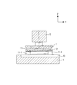
- Fig. 12 schematically illustrates principal components of a vibration type driving device of this type.
- a driven body 5 is held rotatably on a center axis thereof. While the driven body 5 is spaced from a vibrator 1 in Fig. 12, in actuality, the driven body 5 is in pressing contact with upper faces of projections 2-1 and 2-2 of the vibrator 1.
- the vibrator 1 generates driving force in the X-axis direction of Fig. 12, and is located to rotate the driven body 5 in the tangential direction.
- the vibrator 1 includes two projections 2-1 and 2-2 serving as contact portions with the driven body 5.
- the projections 2-1 and 2-2 are arranged on an upper surface of the vibrator 1 in almost the center of the vibrator 1 in the Y-axis direction and symmetrically in the X-axis direction in Fig. 12.
- One of the projections, that is, the projection 2-1 will be described in detail below.
- points P and Q indicate both ends of the projection 2-1 in the Y-axis direction.
- a point O which is closer to the point P, indicates the center point of rotary movement relative to the driven body 5.
- the point P is on the inner peripheral side (radial inner side), and the point Q is on the outer peripheral side (radial outer side).
- the vibrator 1 produces a substantially elliptic motion in the XZ-plane in the projection 2-1 by excitation of vibration.
- the movement direction in which the elliptic motion causes the relative rotation is the X-axis direction.
- driving velocities the velocities of the points P and Q in the X-axis direction
- Vp and Vq the velocities of the points P and Q in the X-axis direction
- circumferential velocities The velocities of the relative rotation of the driven body at the points P and Q in the circumferential direction (hereinafter referred to as circumferential velocities) are designated as Up and Uq, respectively. Since the peripheral velocity is the product of the rotating velocity and the radius of rotation, the relationship between Up and Uq is expressed as follows.
- the rotating velocity of the driven body is lower than the driving velocity. That is, the relationship in magnitude between the driving velocity and the circumferential velocity is expressed as follows.
- angles theta p and theta q between the circumferential velocities and the X-axis have the following relationship.
- Expressions (4) and (5) show that more wear occurs at the point P than at the point Q. That is, the entire contact portions do not uniformly wear, and wear progresses faster on the radial inner side. In this nonuniform wear state, the life of the vibration type driving device becomes shorter than in a uniform wear state. Further, if the wear state is nonuniform, the contact state between the vibrator and the driven body worsens, and this may degrade performance of the vibration type driving device.
- a vibration type driving device includes a vibrator configured to make an elliptic motion of a contact portion by combining vibrations in different vibration modes; and a driven body configured to be rotated relative to the vibrator by the elliptic motion while being in contact with the contact portion.
- a contact pressure of the contact portion with the driven body is lower on a radial inner side than on a radial outer side in a radial direction of the rotation.
- Fig. 1 is a perspective view of a vibration type driving device according to a first embodiment of the present invention.
- Fig. 2 is a partial perspective view of the vibration type driving device of the first embodiment.
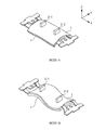
- Fig. 3 illustrates perspective views illustrating vibration modes of a vibrator to which the first embodiment of the present invention is applicable.
- Fig. 4 is a top view of the vibration type driving device of the first embodiment.
- Fig. 5 is a graph showing the characteristic of the vibration type driving device of the first embodiment.
- Fig. 6 is a perspective view of a vibration type driving device according to a modification of the first embodiment.
- Fig. 7 is a perspective view of a vibration type driving device according to a second embodiment of the present invention.
- Fig. 1 is a perspective view of a vibration type driving device according to a first embodiment of the present invention.
- Fig. 2 is a partial perspective view of the vibration type driving device of the first embodiment.
- Fig. 3 illustrates perspective views illustrating vibration modes of a vibr
- Fig. 8 is a partial cross-sectional view of the vibration type driving device of the second embodiment.
- Fig. 9 is a perspective view of a vibration type driving device according to a third embodiment of the present invention.
- Fig. 10A is a plan view of a vibrator unit in the third embodiment.
- Fig. 10B is a cross-sectional view of the vibrator unit in the third embodiment.
- Fig. 11 is a partial cross-sectional view of a vibration type driving device according to a modification of the third embodiment.
- Fig. 12 is a perspective view of a vibration type driving device of the background art of the present invention.
- Fig. 13 schematically illustrates problems to be solved by the present invention.
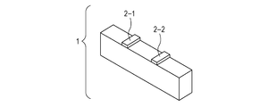
- Fig. 14A schematically illustrates the shape of a vibrator to which the present invention is applicable.
- Fig. 14B schematically illustrates vibration modes of the vibrator to which the present invention is applicable.
- the wear amount of a contact portion in a vibration type driving device depends on the pressure at the contact portion (hereinafter referred to as a contact pressure).
- the wear amount with respect to the driving amount increases as the contact pressure increases.
- more increase in wear amount on a radial inner side than on a radial outer side can be offset by making the contact pressure lower on the radial inner side than on the radial outer side.
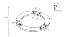
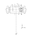
- Fig. 1 is a perspective view illustrating the structure of a principal part of a vibration type driving device 10 according to a first embodiment of the present invention.
- the vibration type driving device 10 illustrated in Fig. 1 includes three vibrator units S1, S2, and S3, a holding member 4 that holds the vibrator units S1, S2, and S3, and an annular driven body 5 held in pressing contact with the vibrator units S1, S2, and S3.
- the three vibrator units S1, S2, and S3 are arranged substantially concentrically with the center axis of the annular driven body 5 (synonymous with "an axis of relative rotation of the driven body) and at positions that substantially trisect the circumference.
- the number of vibrator units can be arbitrarily determined, and for example, may be one or a plural number of two or more. The number can be determined in accordance with the required characteristic.
- each of the vibrator units S1, S2, and S3 is fixed to the holding member 4 in a manner such that upper faces (contact faces) of projections 2-1 and 2-2 serving as contact portions with the driven body 5 are parallel to the XY plane.
- the vibrator units S1, S2, and S3 have the same shape, and each include a vibrator 1 and a connecting member 3 that connects the vibrator 1 to the holding member 4.
- the vibrator 1 includes a vibration plate 6 formed by an elastic plate having two projections 2-1 and 2-2 serving as contact portions with the driven body 5, and a substantially rectangular electromechanical energy transducer 7 joined to the vibration plate 6.
- the vibration plate 6 is formed of a ferromagnetic material such as martensite stainless steel.
- the vibrator 1 is also provided with a flexible printed board (not illustrated) that electrically connects the electromechanical energy transducer 7 to the outside.
- a piezoelectric element or an electrostrictive element can be used as the electromechanical energy transducer 7, a piezoelectric element or an electrostrictive element can be used.
- the connecting member 3 is formed by a thin plate of phosphor bronze or the like, and has a characteristic of a leaf spring. The connecting member 3 elastically holds and fixes the vibrator 1.
- two out-of-plane bending vibration modes (MODE-A and MODE-B) are excited by applying an alternating-current voltage to the electromechanical energy transducer 7 in the vibrator 1.
- MODE-A is a primary out-of-plane bending vibration mode in which two nodes appear parallel to the X-axis direction of Fig. 3 serving as the longitudinal direction of the vibrator 1.
- MODE-A vibration the amplitude of displacement in a direction perpendicular to the faces of the projections 2-1 and 2-2 in contact with the driven body (Z-axis direction) is produced in the projections 2-1 and 2-2.
- MODE-B is a secondary out-of-plane bending vibration mode in which three nodes appear substantially parallel to the Y-axis direction of Fig. 3 in the vibrator 1.
- MODE-B vibration the amplitude of displacement in a direction parallel to the faces of the projections 2-1 and 2-2 in contact with the driven body (X-axis direction) is produced in the projections 2-1 and 2-2.
- an elliptic motion is generated in a substantially XZ plane on the upper faces of the projections 2-1 and 2-2 serving as the contact portions, so that a force for driving the driven body in a direction substantially identical to the X-axis direction is produced.
- This driving force rotates the driven body 5 relative to the vibrator 1.
- the present invention is not limited to the above-described structure of the vibrator, and the vibrator may excite other out-of-plane bending vibration modes. As illustrated in Figs. 14A and 14B, the vibrator may excite another vibration mode.
- a vibrator 1 illustrated in Fig. 14A is shaped like a substantially rectangular parallelepiped.
- a primary longitudinal vibration mode in which the vibrator 1 stretches in the X-axis direction
- a secondary out-of-plane bending vibration mode MODE-B
- three nodes appear substantially parallel to the X-axis direction are excited, as illustrated in Fig. 14B.
- the driven body 5 is formed of a rare-earth magnet material as an annular permanent magnet, and is magnetized in the Z-axis direction.
- the magnetic force of the driven body 5 attracts the vibrator 1 so as to generate a contact pressure between the driven body 5 and the vibrator 1.
- a permanent magnet can be provided in the vibrator and the driven body can be formed of a ferromagnetic material. That is, it is only necessary that one of the vibrator and the driven body includes a permanent magnet and the other includes a ferromagnetic material. Further, each of the vibrator and the driven body can include a permanent magnet.
- a bottom surface of the driven body 5 on the lower side of Fig. 1 is plated with Ni or the like to be resistant to wear, and is also made flat parallel to the XY plane to form a sliding surface.
- This sliding surface contacts the vibrators 1. Since the vibrators 1 are elastically held by the connecting members 3, the sliding surface of the driven body 5 constantly follows the upper faces of the projections 2-1 and 2-2. The contact portions are thus constantly in stable contact with the sliding surface, whereby the driving force of the vibrators 1 is stably transmitted to the driven body 5.
- a guide member not illustrated.
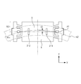
- Fig. 4 is a top view illustrating the positional relationship between the vibrator 1 and the driven body 5.
- the vibrator 1 is substantially symmetrical in the Y-axis direction (direction perpendicular to the driving direction of the contact portions).
- A1 represents the symmetry axis.
- R1 represents a region on a minus side of the symmetry axis A1 of the vibrator 1 in the Y-axis direction, and R2 represents a region on a plus side.
- the difference in attracting force between the region R1 and the region R2 is designated as DELTA_F.
- DELTA_F is a positive value when the attracting force is greater in the region R1 than in the region R2.
- A2 represents the radial center line of the driven body 5
- D represents a position of the symmetry axis A1 relative to the center line A2 in the Y-axis direction.
- the relative position D is a negative value when the vibrator 1 is placed on the minus side in the Y-axis direction.
- the projection position of the driven body 5 on the vibrator 1 is on the plus side in the Y-axis direction. Since the position of the driven body 5 serving as a source of magnetic force is on the radial outer side, the attracting force becomes smaller on the radial inner side than on the radial outer side.
- Fig. 5 is a graph showing the relationship between the relative position D and the difference DELTA_F in attracting force. Here, values calculated by computer simulation are shown. It can be confirmed from Fig. 5 that the difference DELTA_F in attracting force changes according to the relative position D.
- the contact pressure on the radial inner side is set to be lower than the contact pressure on the radial outer side. That is, when a value less than -1.0 mm is selected as the relative position D in Fig. 5, the attracting force is smaller on the radial inner side than on the radial outer side. Hence, the contact pressure is also lower on the radial inner side than on the radial outer side.
- a difference in contact pressure is formed between the radial inner and outer sides so as to control the difference in wear amount between the radial inner and outer sides. Further, the wear amount can be made uniform by suppressing the increase in wear amount on the radial inner side due to rotary driving.
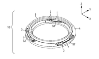
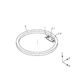
- the first embodiment is also applicable to a vibration type driving device having a structure illustrated in Fig. 6 (modification).
- a driven body 5 is not illustrated.
- Three vibrators 1 are arranged substantially concentrically with the center axis, and are fixed to a holding member 4 at positions that substantially trisect the circumference.
- Upper faces of projections 2-1 and 2-2 of each vibrator 1 are adjusted to substantially coincide with the XY plane. This adjustment can be made, for example, by adjusting the height when bonding the vibrator 1 and the holding member 4 or polishing the upper faces of the projections 2-1 and 2-2 with a surface plate after bonding.
- a connecting member 3 is not provided, and portions of the vibrators 1 fixed to the holding member 4 have high elasticity.
- the posture change of the vibrators 1 due to the force is small.
- even a small posture change may worsen the contact state and reduce the output of the vibration type driving device. That is, when the wear amount becomes larger on the radial inner side than on the radial outer side, performance of the vibration type driving device degrades.
- performance of the vibration type driving device can also be stabilized by uniformizing the wear amount through the adjustment of the contact pressure that has been described with reference to Figs. 4 and 5.
- Fig. 7 is a perspective view illustrating the structure of the principal part of a vibration type driving device 10 according to the second embodiment of the present invention.
- Fig. 8 is a cross-sectional view of the vibration type driving device 10 of Fig. 7, taken along a plane including a vibrator unit S1.
- Vibrator units S1, S2, and S3 and a holding member 4 have the same structures as those illustrated in Fig. 1 and so on, so descriptions thereof are skipped.
- a driven body 5 is formed of a rare-earth magnet material in a substantially annular shape, and is magnetized in the Z-axis direction.
- a ring-shaped friction member 8 is integrally bonded to a surface of the driven body 5 facing vibrators 1.
- the thickness of the driven body 5 is smaller in the Z-axis direction (rotation axis direction) on the radial inner side than on the radial outer side so that the magnetic flux density is lower on the radial inner side than on the radial outer side.
- the magnetic attracting force produced between the driven body 5 and the vibrators 1 is made smaller on the radial inner side than on the radial outer side.
- the contact pressure can be made lower on the radial inner side than on the radial outer side.
- a permanent magnet can be provided in the vibrator and the driven body can be formed of a ferromagnetic material. That is, it only necessary that that one of the vibrator and the driven body includes a permanent magnet and the other includes a ferromagnetic material. Further, each of the vibrator and the driven body can include a permanent magnet.
- the present invention can be applied to this structure by forming a difference in thickness of the permanent magnet between the radial inner and outer sides so that the magnetic flux density is lower on the radial inner side than on the radial outer side.
- a pressing member is provided to press vibrators toward a driven body.
- a contact pressure is given by restoring force generated by elastic deformation of the pressing member.
- Fig. 9 is a perspective view illustrating the structure of the principal part of a vibration type driving device 10 according to the third embodiment of the present invention. Descriptions of the same structures as those described with reference to Fig. 1 and so on are skipped, and only different structures will be described below.
- a driven body 5 is formed of martensite stainless steel in a substantially annular shape, and a surface thereof is azotized to increase wear resistance.
- Fig. 10A is a plan view of one vibrator unit.
- the plus side in the Y-axis direction is the radial outer side, and the minus side is the radial inner side.
- Fig. 10B is a cross-sectional view of the vibrator unit.
- a vibrator 1 that forms the vibrator unit is the same as that adopted in the first embodiment.
- the vibrator 1 is combined with a pressing member 11 with a metallic spacer component 12 being disposed therebetween.
- the pressing member 11 serves to hold the vibrator 1 and to generate a contact pressure between the vibrator 1 and the driven body 5.
- the pressing member 11 is formed by a thin plate of a material suitable for a spring component, for example, phosphor bronze.
- the pressing member 11 includes a contact portion in contact with the spacer component 12, two first deforming portions 11-1, and two second deforming portions 11-2.
- the width of the first deforming portions 11-1 is smaller than that of the second deforming portions 11-2.
- the rigidity of the first deforming portions 11-1 is lower than that of the second deforming portions 11-2.
- each vibrator 1 is held while being pushed in the -Z-axis direction via the driven body 5 by a desired amount. That is, the first and second deforming portions 11-1 and 11-2 are held while bending in the Z-axis direction, and the restoring forces thereof generate a contact pressure between the vibrator 1 and the driven body 5. Since the rigidity of the first deforming portions 11-1 is lower than that of the second deforming portions 11-2, as described above, the contact pressure is lower on the radial inner side than on the radial outer side.
- Fig. 11 illustrates the structure of a modification of the third embodiment.
- first deforming portions 11-1 and second deforming portions 11-2 in a pressing member 11 are substantially equal in width and rigidity.
- a pressing-member mounting portion 13 of a holding member 4 is inclined such as to be higher on the radial outer side in the Z-axis direction (rotation axis direction).
- vibrator units mounted on the pressing-member mounting portion 13 are also higher on the radial outer side. That is, projections of vibrators 1 are higher on the radial outer side than on the radial inner side.
- the vibrators 1 When the vibrators 1 are pushed in the -Z-axis direction via a driven body 5 in this state, the first deforming portions 11-1 and the second deforming portions 11-2 bend, and generate restoring forces. Since a sliding surface of the driven body 5 follows contact portions of the vibrators 1, the bending amount and restoring force of the second deforming portions 11-2 are larger than those of the first deforming portions 11-1. As a result, the contact pressures at the contact portions are also lower on the radial inner side than on the radial outer side.
- the restoring force of the second deforming portions 11-2 can be made larger than that of the first deforming portions 11-1 by forming a difference in height of other members, such as the vibrators, between the radial inner and outer sides.
- the contact pressure can be made lower on the radial inner side than on the radial outer side by making the restoring force due to elastic deformation of the pressing member smaller on the radial inner side than on the radial outer side. This can eliminate the difference in wear amount between the radial inner and outer sides.
Landscapes
- Engineering & Computer Science (AREA)
- General Engineering & Computer Science (AREA)
- Chemical & Material Sciences (AREA)
- Combustion & Propulsion (AREA)
- Mechanical Engineering (AREA)
- General Electrical Machinery Utilizing Piezoelectricity, Electrostriction Or Magnetostriction (AREA)
Abstract
Description

Claims (9)
- A vibration type driving device comprising:
a vibrator configured to make an elliptic motion of a contact portion by combining vibrations in different vibration modes; and
a driven body configured to be rotated relative to the vibrator by the elliptic motion while being in contact with the contact portion,
wherein a contact pressure of the contact portion with the driven body is lower on a radial inner side than on a radial outer side in a radial direction of the rotation. - The vibration type driving device according to Claim 1,
wherein one of the vibrator and the driven body includes a permanent magnet and the other includes a ferromagnetic material,
wherein the contact pressure is generated by an attracting force produced between the permanent magnet and the ferromagnetic material, and
wherein the attracting force is smaller on the radial inner side than on the radial outer side so that the contact pressure of the contact portion with the driven body is lower on the radial inner side than on the radial outer side. - The vibration type driving device according to Claim 2, wherein positions of the vibrator and the driven body in the radial direction are determined so that the attracting force is smaller on the radial inner side than on the radial outer side.
- The vibration type driving device according to Claim 2,
wherein the driven body includes the permanent magnet, and
wherein a thickness of the driven body in an axial direction of the rotation is smaller on the radial inner side than on the radial outer side so that the attracting force is smaller on the radial inner side than on the radial outer side. - The vibration type driving device according to Claim 1, further comprising:
a pressing member configured to press the vibrator toward the driven body,
wherein the contact pressure is generated by a restoring force produced by elastic deformation of the pressing member, and
wherein the restoring force is smaller on the radial inner side than on the radial outer side so that the contact pressure of the contact portion with the driven body is lower on the radial inner side than on the radial outer side. - The vibration type driving device according to Claim 5,
wherein the pressing member includes an elastically deformable first deforming portion located on the radial inner side and an elastically deformable second deforming portion located on the radial outer side, and
wherein a rigidity of the first deforming portion is lower than a rigidity of the second deforming portion. - The vibration type driving device according to Claim 6, wherein the first deforming portion is narrower than the second deforming portion.
- The vibration type driving device according to Claim 5, further comprising a holding member configured to hold the vibrator,
wherein a height of the vibrator or the holding member in the axial direction of the rotation is smaller on the radial inner side than on the radial outer side so that the restoring force is smaller on the radial inner side than on the radial outer side. - The vibration type driving device according to any one of Claims 1 to 8, wherein a plurality of the vibrators relatively rotate the driven body.
Priority Applications (3)
| Application Number | Priority Date | Filing Date | Title |
|---|---|---|---|
| US13/809,574 US9099941B2 (en) | 2010-07-15 | 2011-07-04 | Vibration type driving device |
| CN201180034122.7A CN102986130B (en) | 2010-07-15 | 2011-07-04 | Vibration type driving device |
| US14/788,006 US9654029B2 (en) | 2010-07-15 | 2015-06-30 | Vibration type driving device |
Applications Claiming Priority (2)
| Application Number | Priority Date | Filing Date | Title |
|---|---|---|---|
| JP2010160592A JP5641800B2 (en) | 2010-07-15 | 2010-07-15 | Vibration type driving device |
| JP2010-160592 | 2010-07-15 |
Related Child Applications (2)
| Application Number | Title | Priority Date | Filing Date |
|---|---|---|---|
| US13/809,574 A-371-Of-International US9099941B2 (en) | 2010-07-15 | 2011-07-04 | Vibration type driving device |
| US14/788,006 Continuation US9654029B2 (en) | 2010-07-15 | 2015-06-30 | Vibration type driving device |
Publications (2)
| Publication Number | Publication Date |
|---|---|
| WO2012008114A2 true WO2012008114A2 (en) | 2012-01-19 |
| WO2012008114A3 WO2012008114A3 (en) | 2012-03-08 |
Family
ID=44509550
Family Applications (1)
| Application Number | Title | Priority Date | Filing Date |
|---|---|---|---|
| PCT/JP2011/003810 WO2012008114A2 (en) | 2010-07-15 | 2011-07-04 | Vibration type driving device |
Country Status (4)
| Country | Link |
|---|---|
| US (2) | US9099941B2 (en) |
| JP (1) | JP5641800B2 (en) |
| CN (1) | CN102986130B (en) |
| WO (1) | WO2012008114A2 (en) |
Cited By (1)
| Publication number | Priority date | Publication date | Assignee | Title |
|---|---|---|---|---|
| JP2014018027A (en) * | 2012-07-11 | 2014-01-30 | Canon Inc | Vibration type actuator, imaging apparatus, and stage |
Families Citing this family (7)
| Publication number | Priority date | Publication date | Assignee | Title |
|---|---|---|---|---|
| JP5773900B2 (en) * | 2012-01-30 | 2015-09-02 | キヤノン株式会社 | motor |
| JP6021559B2 (en) * | 2012-09-28 | 2016-11-09 | キヤノン株式会社 | Vibration type driving device and imaging device |
| JP6218501B2 (en) | 2013-08-26 | 2017-10-25 | キヤノン株式会社 | Vibration wave motor |
| JP6465587B2 (en) * | 2014-08-22 | 2019-02-06 | キヤノン株式会社 | Vibrator unit, vibration type actuator, and imaging device |
| JP6866128B2 (en) * | 2015-12-04 | 2021-04-28 | キヤノン株式会社 | Vibration type actuator drive method, vibration type drive device and mechanical device |
| JP6771939B2 (en) * | 2016-04-25 | 2020-10-21 | キヤノン株式会社 | Vibration type actuators and electronic devices |
| JP6833439B2 (en) * | 2016-10-05 | 2021-02-24 | キヤノン株式会社 | Vibration type drive device and its control method and electronic equipment |
Citations (2)
| Publication number | Priority date | Publication date | Assignee | Title |
|---|---|---|---|---|
| US20050242686A1 (en) | 2003-03-28 | 2005-11-03 | Canon Kabushiki Kaisha | Vibration-type driving device, control apparatus for controlling the driving of the vibration-type driving device, and electronic equipment having the vibration-type driving device and the control apparatus |
| JP2010160592A (en) | 2009-01-07 | 2010-07-22 | Hitachi Ltd | Service relay device, service relay method, and program for implementing the method |
Family Cites Families (11)
| Publication number | Priority date | Publication date | Assignee | Title |
|---|---|---|---|---|
| JPS6118369A (en) | 1984-07-03 | 1986-01-27 | Matsushita Electric Ind Co Ltd | Piezoelectric motor |
| US5416375A (en) * | 1992-06-15 | 1995-05-16 | Olympus Optical Co., Ltd. | Ultrasonic motor |
| US5698930A (en) | 1993-11-15 | 1997-12-16 | Nikon Corporation | Ultrasonic wave motor and method of manufacture |
| JP2001037265A (en) | 1999-07-15 | 2001-02-09 | Canon Inc | Vibrating driver and apparatus using the same |
| JP2002315336A (en) | 2001-04-12 | 2002-10-25 | Diamond Electric Mfg Co Ltd | Switching power supply device |
| JP2004304887A (en) | 2003-03-28 | 2004-10-28 | Canon Inc | Oscillatory drive unit |
| JP4576214B2 (en) | 2004-11-26 | 2010-11-04 | オリンパスイメージング株式会社 | Ultrasonic motor and lens barrel |
| JP4290168B2 (en) * | 2005-03-31 | 2009-07-01 | キヤノン株式会社 | Vibration wave drive |
| KR101108455B1 (en) | 2005-11-10 | 2012-01-31 | 가부시키가이샤 도요다 지도숏키 | Ultrasonic motor |
| JP2007185056A (en) * | 2006-01-10 | 2007-07-19 | Sony Corp | Exciting method of elastic vibration body, and vibration drive device |
| US20100283656A1 (en) * | 2006-08-24 | 2010-11-11 | Zavrel Jr Robert J | Method and system for jamming simultaneously with communication using omni-directional antenna |
-
2010
- 2010-07-15 JP JP2010160592A patent/JP5641800B2/en not_active Expired - Fee Related
-
2011
- 2011-07-04 CN CN201180034122.7A patent/CN102986130B/en not_active Expired - Fee Related
- 2011-07-04 US US13/809,574 patent/US9099941B2/en not_active Expired - Fee Related
- 2011-07-04 WO PCT/JP2011/003810 patent/WO2012008114A2/en active Application Filing
-
2015
- 2015-06-30 US US14/788,006 patent/US9654029B2/en active Active
Patent Citations (2)
| Publication number | Priority date | Publication date | Assignee | Title |
|---|---|---|---|---|
| US20050242686A1 (en) | 2003-03-28 | 2005-11-03 | Canon Kabushiki Kaisha | Vibration-type driving device, control apparatus for controlling the driving of the vibration-type driving device, and electronic equipment having the vibration-type driving device and the control apparatus |
| JP2010160592A (en) | 2009-01-07 | 2010-07-22 | Hitachi Ltd | Service relay device, service relay method, and program for implementing the method |
Cited By (1)
| Publication number | Priority date | Publication date | Assignee | Title |
|---|---|---|---|---|
| JP2014018027A (en) * | 2012-07-11 | 2014-01-30 | Canon Inc | Vibration type actuator, imaging apparatus, and stage |
Also Published As
| Publication number | Publication date |
|---|---|
| US9654029B2 (en) | 2017-05-16 |
| CN102986130B (en) | 2015-07-01 |
| WO2012008114A3 (en) | 2012-03-08 |
| JP2012023883A (en) | 2012-02-02 |
| JP5641800B2 (en) | 2014-12-17 |
| US9099941B2 (en) | 2015-08-04 |
| US20130113339A1 (en) | 2013-05-09 |
| CN102986130A (en) | 2013-03-20 |
| US20150303833A1 (en) | 2015-10-22 |
Similar Documents
| Publication | Publication Date | Title |
|---|---|---|
| US9654029B2 (en) | Vibration type driving device | |
| JP2012213271A (en) | Vibration type drive device | |
| EP2242123B1 (en) | Vibration wave driving device | |
| JP2009254198A (en) | Ultrasonic motor and ultrasonic oscillator | |
| WO2010088937A1 (en) | Piezoelectric actuator | |
| JP6598488B2 (en) | Vibration wave motor | |
| JP2011217595A (en) | Vibration wave driving apparatus and method for manufacturing vibrating body thereof | |
| US8350446B2 (en) | Vibratory actuator and drive device using the same | |
| JP2013156295A (en) | Lens drive device | |
| JP2000324859A (en) | Piezoelectric actuator | |
| CN102067004B (en) | Oscillating actuator, and lens barrel and camera provided with the oscillating actuator | |
| JP2006271065A (en) | Driving device | |
| JP6269223B2 (en) | Piezoelectric motor | |
| JP2008072785A (en) | Vibrating type linear driving device and camera lens | |
| JP4645229B2 (en) | Drive device | |
| JP5029948B2 (en) | Ultrasonic motor | |
| US7687974B2 (en) | Vibration type driving apparatus | |
| US20240171092A1 (en) | Vibration actuator and method for manufacturing vibration actuator | |
| JP6269224B2 (en) | Piezoelectric motor | |
| JP3814100B2 (en) | Piezoelectric actuator | |
| JP2018099002A (en) | Vibration type actuator, lens barrel having the same, imaging apparatus, and stage device | |
| JP4910381B2 (en) | Drive device, drive system, and drive method | |
| CN114123855A (en) | Vibration-type actuator, rotation driving apparatus, and image pickup apparatus | |
| JP5669446B2 (en) | Driving mechanism of moving body | |
| KR20070017143A (en) | Vibration wave driven apparatus and vibrator |
Legal Events
| Date | Code | Title | Description |
|---|---|---|---|
| WWE | Wipo information: entry into national phase |
Ref document number: 201180034122.7 Country of ref document: CN |
|
| 121 | Ep: the epo has been informed by wipo that ep was designated in this application |
Ref document number: 11748476 Country of ref document: EP Kind code of ref document: A2 |
|
| WWE | Wipo information: entry into national phase |
Ref document number: 13809574 Country of ref document: US |
|
| NENP | Non-entry into the national phase |
Ref country code: DE |
|
| 122 | Ep: pct application non-entry in european phase |
Ref document number: 11748476 Country of ref document: EP Kind code of ref document: A2 |