WO2012008050A1 - Engine starting device and engine starting method - Google Patents
Engine starting device and engine starting method Download PDFInfo
- Publication number
- WO2012008050A1 WO2012008050A1 PCT/JP2010/062092 JP2010062092W WO2012008050A1 WO 2012008050 A1 WO2012008050 A1 WO 2012008050A1 JP 2010062092 W JP2010062092 W JP 2010062092W WO 2012008050 A1 WO2012008050 A1 WO 2012008050A1
- Authority
- WO
- WIPO (PCT)
- Prior art keywords
- engine
- actuator
- gear
- motor
- starter
- Prior art date
Links
Images


Classifications
-
- F—MECHANICAL ENGINEERING; LIGHTING; HEATING; WEAPONS; BLASTING
- F02—COMBUSTION ENGINES; HOT-GAS OR COMBUSTION-PRODUCT ENGINE PLANTS
- F02N—STARTING OF COMBUSTION ENGINES; STARTING AIDS FOR SUCH ENGINES, NOT OTHERWISE PROVIDED FOR
- F02N11/00—Starting of engines by means of electric motors
- F02N11/08—Circuits or control means specially adapted for starting of engines
- F02N11/0851—Circuits or control means specially adapted for starting of engines characterised by means for controlling the engagement or disengagement between engine and starter, e.g. meshing of pinion and engine gear
-
- F—MECHANICAL ENGINEERING; LIGHTING; HEATING; WEAPONS; BLASTING
- F02—COMBUSTION ENGINES; HOT-GAS OR COMBUSTION-PRODUCT ENGINE PLANTS
- F02N—STARTING OF COMBUSTION ENGINES; STARTING AIDS FOR SUCH ENGINES, NOT OTHERWISE PROVIDED FOR
- F02N15/00—Other power-operated starting apparatus; Component parts, details, or accessories, not provided for in, or of interest apart from groups F02N5/00 - F02N13/00
- F02N15/02—Gearing between starting-engines and started engines; Engagement or disengagement thereof
- F02N15/04—Gearing between starting-engines and started engines; Engagement or disengagement thereof the gearing including disengaging toothed gears
- F02N15/06—Gearing between starting-engines and started engines; Engagement or disengagement thereof the gearing including disengaging toothed gears the toothed gears being moved by axial displacement
- F02N15/067—Gearing between starting-engines and started engines; Engagement or disengagement thereof the gearing including disengaging toothed gears the toothed gears being moved by axial displacement the starter comprising an electro-magnetically actuated lever
-
- F—MECHANICAL ENGINEERING; LIGHTING; HEATING; WEAPONS; BLASTING
- F02—COMBUSTION ENGINES; HOT-GAS OR COMBUSTION-PRODUCT ENGINE PLANTS
- F02N—STARTING OF COMBUSTION ENGINES; STARTING AIDS FOR SUCH ENGINES, NOT OTHERWISE PROVIDED FOR
- F02N11/00—Starting of engines by means of electric motors
- F02N11/08—Circuits or control means specially adapted for starting of engines
- F02N11/0851—Circuits or control means specially adapted for starting of engines characterised by means for controlling the engagement or disengagement between engine and starter, e.g. meshing of pinion and engine gear
- F02N11/0855—Circuits or control means specially adapted for starting of engines characterised by means for controlling the engagement or disengagement between engine and starter, e.g. meshing of pinion and engine gear during engine shutdown or after engine stop before start command, e.g. pre-engagement of pinion
-
- F—MECHANICAL ENGINEERING; LIGHTING; HEATING; WEAPONS; BLASTING
- F02—COMBUSTION ENGINES; HOT-GAS OR COMBUSTION-PRODUCT ENGINE PLANTS
- F02D—CONTROLLING COMBUSTION ENGINES
- F02D2250/00—Engine control related to specific problems or objectives
- F02D2250/18—Control of the engine output torque
- F02D2250/24—Control of the engine output torque by using an external load, e.g. a generator
-
- F—MECHANICAL ENGINEERING; LIGHTING; HEATING; WEAPONS; BLASTING
- F02—COMBUSTION ENGINES; HOT-GAS OR COMBUSTION-PRODUCT ENGINE PLANTS
- F02D—CONTROLLING COMBUSTION ENGINES
- F02D41/00—Electrical control of supply of combustible mixture or its constituents
- F02D41/02—Circuit arrangements for generating control signals
- F02D41/04—Introducing corrections for particular operating conditions
- F02D41/042—Introducing corrections for particular operating conditions for stopping the engine
-
- F—MECHANICAL ENGINEERING; LIGHTING; HEATING; WEAPONS; BLASTING
- F02—COMBUSTION ENGINES; HOT-GAS OR COMBUSTION-PRODUCT ENGINE PLANTS
- F02N—STARTING OF COMBUSTION ENGINES; STARTING AIDS FOR SUCH ENGINES, NOT OTHERWISE PROVIDED FOR
- F02N2200/00—Parameters used for control of starting apparatus
- F02N2200/08—Parameters used for control of starting apparatus said parameters being related to the vehicle or its components
- F02N2200/0806—Air condition state
Definitions
- the present invention relates to an engine starting device and an engine starting method, and in particular, an actuator that moves a pinion gear to engage with a ring gear provided on the outer periphery of an engine flywheel or a drive plate, and a motor that rotates the pinion gear.
- the present invention relates to a technique for controlling a starter that is individually controlled.
- the engine may be restarted while the engine speed is relatively high.
- the engine in the conventional starter in which the push-out of the pinion gear for rotating the engine and the rotation of the pinion gear are performed by one drive command, the engine is designed to facilitate the engagement between the pinion gear and the engine ring gear.
- the starter is driven after the rotational speed of the motor has sufficiently decreased. If it does so, time delay will generate
- Patent Document 1 uses a starter having a configuration in which the engagement operation of the pinion gear and the rotation operation of the pinion gear can be performed independently.
- a restart request is generated during the engine rotation drop period immediately after the stop request is generated, the pinion gear is rotated prior to the engagement operation of the pinion gear, and when the rotation speed of the pinion gear is synchronized with the engine rotation speed, Disclosed is a technique for restarting an engine by engaging a pinion gear.
- the present invention has been made to solve the above-described problems, and an object of the present invention is to provide an engine starter and an engine start method that suppress deterioration of engine startability.
- An engine starter includes a starter that starts the engine, a device that is connected to the crankshaft of the engine and varies the engine load, and a starter control device.
- the starter includes a second gear that can be engaged with the first gear coupled to the crankshaft of the engine, an actuator that moves the second gear to a position that engages with the first gear in the driving state, And a motor for rotating the second gear.
- the control device can individually drive each of the actuator and the motor.
- the control device has a rotation mode in which the motor is driven prior to driving the actuator. When executing the rotation mode, the control device suppresses load fluctuations of the engine and the device before driving the actuator.
- control device releases the suppression of the fluctuation of the load when the engagement between the first gear and the second gear is completed.
- the device includes at least one of an air conditioner compressor and an alternator.
- the control device holds the operating state of the device from the first time after the start request to the second time when the actuator is operated.
- control device holds the operating state of the engine from the first time after the start request to the second time when the actuator is operated.
- control device controls any one of the engine and the device so as to prohibit the fluctuation of the engine load from the first time after the start request to the second time when the actuator is operated.
- the device includes at least one of an air conditioner compressor and an alternator.
- the control device prohibits the operation of the device from the first time after the start request to the second time when the actuator is operated.
- control device prohibits a change in the control value for the engine from the first time after the start request to the second time when the actuator is operated.
- control device controls the actuator and the motor so as to start the engine by selecting any one of a plurality of control modes based on the rotational speed of the engine.
- the plurality of control modes include a first control mode for operating the actuator so that the second gear moves toward the first gear after execution of the rotation mode, and operating the motor after starting the operation of the actuator. For the second control mode.
- the engine in the engine starting method is provided with a starter for starting the engine, a device that is connected to the crankshaft of the engine and varies the engine load, and a starter control device.
- the starter includes a second gear that can be engaged with the first gear coupled to the crankshaft of the engine, an actuator that moves the second gear to a position that engages with the first gear in the driving state, And a motor for rotating the second gear.
- Each of the actuator and the motor can be driven individually.
- the starting method includes a step of driving the actuator and the motor in a rotation mode for driving the motor prior to the driving of the actuator, and a step of suppressing load fluctuations of the engine and equipment before the actuator is driven when the rotation mode is executed. Is provided.
- the engine 100 or the device When there is an engine start request, the engine 100 or the device is controlled so as to suppress the fluctuation of the engine load before the time when the actuator is operated, thereby suppressing the rapid fluctuation of the engine rotation speed. . Therefore, when the actuator is operated after the motor is driven, the rotational speed of the engine can be accurately predicted. As a result, the motor drive start timing for synchronizing the engine rotation speed and the motor rotation speed can be accurately set. Therefore, it is possible to provide an engine starter and an engine start method that suppress deterioration of engine startability.
- 1 is an overall block diagram of a vehicle. It is a functional block diagram of ECU. It is a figure for demonstrating the transition of the operation mode of a starter. It is a figure for demonstrating the drive mode at the time of engine starting operation
- FIG. 1 is an overall block diagram of the vehicle 10.
- vehicle 10 includes an engine 100, a battery 120, a starter 200, a control device (hereinafter also referred to as an ECU (Electronic Control Unit)) 300, and relays RY1 and RY2.
- Starter 200 includes a motor 220, an actuator 232, a connecting portion 240, an output member 250, and a pinion gear 260.
- the actuator 232 includes a plunger 210 and a solenoid 230.
- Engine 100 generates a driving force for traveling vehicle 10.
- a crankshaft 111 that is an output shaft of the engine 100 is connected to drive wheels via a power transmission device that includes a clutch, a speed reducer, and the like.
- the engine 100 is provided with an intake passage 166 for supplying air to the engine 100.
- the intake passage 166 is provided with a throttle valve 164 for adjusting the flow rate of air flowing through the intake passage 166.
- the throttle valve 164 is operated by a throttle motor 160.
- Throttle motor 160 is driven based on control signal THC from ECU 300.
- the position of the throttle valve 164, that is, the throttle opening is detected by a throttle position sensor 162.
- Throttle position sensor 162 outputs detected value TH to ECU 300.
- the engine 100 may be provided with a valve driving actuator 172 for driving the intake valve and the exhaust valve.
- the valve driving actuator 172 may be, for example, an actuator that adjusts each valve opening amount by directly driving the intake valve and the exhaust valve, or for changing the closing timing and the lift amount of the intake valve and the exhaust valve.
- the actuator may be used.
- the valve driving actuator 172 is driven based on a control signal VB from the ECU.
- the engine 100 is provided with a rotation speed sensor 115.
- the rotational speed sensor 115 detects the rotational speed Ne of the engine 100 and outputs the detection result to the ECU 300.
- the battery 120 is a power storage element configured to be chargeable / dischargeable.
- the battery 120 includes a secondary battery such as a lithium ion battery, a nickel metal hydride battery, or a lead battery.
- the battery 120 may be comprised by electrical storage elements, such as an electric double layer capacitor.
- the engine 100 is provided with an alternator 132 and an air conditioner compressor 134 as devices for changing the load of the engine 100.
- a pulley 136 is provided on the input shaft of the alternator 132.
- a pulley 138 is provided on the input shaft of the air conditioner compressor 134.
- a pulley 168 is provided on the crankshaft 111 of the engine 100.
- the pulleys 136, 138 and 168 are connected using a belt 170. Therefore, the rotational force of crankshaft 111 of engine 100 is transmitted to pulleys 136 and 138 via pulley 168 and belt 170.
- the alternator 132 generates electric power using the rotational force transmitted to the pulley 136 by exciting a built-in electromagnetic coil based on a control signal ALT from the ECU 300.
- the alternator 132 charges the battery 120 by supplying the generated power to the battery 120 via an inverter, converter, or the like (not shown).
- the alternator 132 may charge the battery 120 by supplying the power generated by the alternator 132 to the battery 120 via an inverter and a DC / DC converter 127 (not shown).
- the amount of power generated by the alternator 132 is controlled by the ECU 300.
- the air conditioner compressor 134 operates based on a control signal AC from the ECU 300.
- the air conditioner compressor 134 incorporates an electromagnetic clutch 142.
- the electromagnetic clutch 142 is engaged or released based on a control signal AC from the ECU 300.
- the air conditioner compressor 134 is operated by the integral rotation of the pulley 138 and the input shaft of the air conditioner compressor 134.
- a starter for engine 100 includes a starter 200 for starting engine 100, devices connected to engine crankshaft 111 and changing the load of engine 100 (alternator 132, air conditioner compressor 134), and the like. And an ECU 300 that is a control device of the starter 200.
- the battery 120 is connected to the starter 200 via relays RY1 and RY2 controlled by the ECU 300.
- the battery 120 supplies the drive power supply voltage to the starter 200 by closing the relays RY1 and RY2.
- the negative electrode of battery 120 is connected to the body ground of vehicle 10.
- the battery 120 is provided with a voltage sensor 125.
- Voltage sensor 125 detects output voltage VB of battery 120 and outputs the detected value to ECU 300.
- the voltage of the battery 120 is supplied via the DC / DC converter 127 to the ECU 300 and auxiliary equipment such as an inverter of the air conditioner.
- the DC / DC converter 127 is controlled by the ECU 300 so as to maintain the voltage supplied to the ECU 300 and the like. For example, in consideration of the fact that the voltage of the battery 120 is temporarily reduced by driving the motor 220 and cranking the engine 100, the voltage is controlled to increase when the motor 220 is driven.
- the DC / DC converter 127 increases the voltage when the start request signal of the engine 100 is output. To be controlled.
- the control method of the DC / DC converter 127 is not limited to this.
- relay RY1 The one end of relay RY1 is connected to the positive electrode of battery 120, and the other end of relay RY1 is connected to one end of solenoid 230 in starter 200.
- the relay RY1 is controlled by a control signal SE1 from the ECU 300, and switches between supply and interruption of the power supply voltage from the battery 120 to the solenoid 230.
- the one end of the relay RY2 is connected to the positive electrode of the battery 120, and the other end of the relay RY2 is connected to the motor 220 in the starter 200.
- Relay RY ⁇ b> 2 is controlled by a control signal SE ⁇ b> 2 from ECU 300, and switches between supply and interruption of power supply voltage from battery 120 to motor 220.
- a voltage sensor 130 is provided on a power line connecting relay RY2 and motor 220. Voltage sensor 130 detects motor voltage VM and outputs the detected value to ECU 300.
- starter 200 is engaged with a second gear that can be engaged with a first gear coupled to crankshaft 111 of engine 100, and in a driving state, second gear is engaged with first gear. It includes an actuator 232 that moves to a matching position, and a motor 220 that rotates the second gear.
- first gear is ring gear 110 coupled to crankshaft 111 of engine 100
- second gear is pinion gear 260.
- the supply of the power supply voltage to the motor 220 and the solenoid 230 in the starter 200 can be independently controlled by the relays RY1 and RY2.
- the output member 250 is coupled to a rotating shaft of a rotor (not shown) inside the motor by, for example, a linear spline.
- a pinion gear 260 is provided at the end of the output member 250 opposite to the motor 220.
- solenoid 230 As described above, one end of the solenoid 230 is connected to the relay RY1, and the other end of the solenoid 230 is connected to the body ground.
- relay RY1 When relay RY1 is closed and solenoid 230 is excited, solenoid 230 attracts plunger 210 in the direction of the arrow.
- the plunger 210 is coupled to the output member 250 through the connecting portion 240.
- the solenoid 230 is excited and the plunger 210 is attracted in the direction of the arrow.
- the output member 250 moves away from the standby position shown in FIG. 1 in the direction opposite to the operation direction of the plunger 210, that is, the pinion gear 260 moves away from the main body of the motor 220 by the connecting portion 240 to which the fulcrum 245 is fixed. Moved in the direction.
- the plunger 210 is biased by a spring mechanism (not shown) in the direction opposite to the arrow in FIG. 1, and is returned to the standby position when the solenoid 230 is de-energized.
- the pinion gear 260 is attached to the outer periphery of the flywheel or drive plate attached to the crankshaft 111 of the engine 100. Engage with. Then, with the pinion gear 260 and the ring gear 110 engaged, the pinion gear 260 rotates, whereby the engine 100 is cranked and the engine 100 is started.
- actuator 232 that moves pinion gear 260 to engage with ring gear 110 provided on the outer periphery of flywheel or drive plate of engine 100, and motor 220 that rotates pinion gear 260, are controlled individually.
- a one-way clutch may be provided between the output member 250 and the rotor shaft of the motor 220 so that the rotor of the motor 220 is not rotated by the rotation operation of the ring gear 110.
- the actuator 232 in FIG. 1 is a mechanism that can transmit the rotation of the pinion gear 260 to the ring gear 110 and can switch between a state in which the pinion gear 260 and the ring gear 110 are engaged and a state in which both are not engaged.
- the mechanism is not limited to the above-described mechanism.
- a mechanism in which the pinion gear 260 and the ring gear 110 are engaged by moving the shaft of the output member 250 in the radial direction of the pinion gear 260 may be used.
- ECU 300 includes a CPU (Central Processing Unit), a storage device, and an input / output buffer, and inputs each sensor and outputs a control command to each device.
- CPU Central Processing Unit
- storage device e.g., a hard disk drive
- input / output buffer e.g., a hard disk drive
- ECU 300 receives a signal ACC representing an operation amount of accelerator pedal 140 from a sensor (not shown) provided on accelerator pedal 140.
- ECU 300 receives a signal BRK representing the operation amount of brake pedal 150 from a sensor (not shown) provided on brake pedal 150.
- ECU 300 also receives a start operation signal IG-ON due to an ignition operation by the driver. Based on these pieces of information, ECU 300 generates a start request signal and a stop request signal for engine 100, and outputs control signals SE1 and SE2 in accordance therewith to control the operation of starter 200.
- ECU 300 can drive each of actuator 232 and motor 220 individually.
- ECU 300 has a rotation mode in which motor 220 is driven prior to driving actuator 232.
- ECU 300 suppresses load fluctuations of engine 100 and the above-described devices (that is, alternator 132 and air conditioner compressor 134) before driving actuator 232 when the rotation mode is executed.
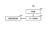
- ECU 300 The function of ECU 300 will be described with reference to FIG.
- the functions of ECU 300 described below may be realized by software, may be realized by hardware, or may be realized by cooperation of software and hardware.
- ECU 300 includes a determination unit 302, a starter control unit 304, and a fluctuation suppression control unit 306.
- Determination unit 302 determines whether or not there is a request to start engine 100. For example, when the amount of operation of brake pedal 150 by the driver decreases to zero, determination unit 302 determines that there is a request to start engine 100. More specifically, determination unit 302 determines that there is a request to start engine 100 when the amount of operation of brake pedal 150 by the driver decreases to zero while engine 100 and vehicle 10 are stopped. The method for determining whether or not the determination unit 302 has a request to start the engine 100 is not limited to this. When ECU 300 determines that there is a request to start engine 100, ECU 300 generates a start request signal for engine 100 and outputs control signals SE1 and SE2 accordingly.
- starter control unit 304 when a start request signal for engine 100 is generated, that is, when it is determined that there is a start request for engine 100, a plurality of starter control units 304 are based on the rotational speed Ne of engine 100.
- the actuator 232 and the motor 220 are controlled so that the engine 100 is started by selecting any one of the control modes.
- the plurality of control modes are a first mode in which the actuator 232 and the motor 220 are controlled so that the pinion gear 260 starts rotating after the pinion gear 260 moves toward the ring gear 110, and after the pinion gear 260 starts rotating.
- a second mode in which the actuator 232 and the motor 220 are controlled so that the pinion gear 260 moves toward the ring gear 110.
- the starter control unit 304 starts the rotation of the pinion gear 260 without selecting any one of the plurality of control modes.
- the actuator 232 and the motor 220 may be controlled to move toward the ring gear 110.
- the starter control unit 304 controls the actuator 232 so that the pinion gear 260 moves toward the ring gear 110 when the determination unit 302 determines that there is a request to start the engine 100. Then, after the pinion gear 260 moves toward the ring gear 110, the motor 220 is controlled so that the pinion gear 260 rotates.
- the starter control unit 304 selects the second mode
- the motor 220 is controlled so that the pinion gear 260 starts to rotate when the determination unit 302 determines that there is a request to start the engine 100, and the pinion gear
- the actuator 232 is controlled so that the pinion gear 260 moves toward the ring gear 110 after the rotation starts.
- the starter control unit 304 selects the first mode when the rotational speed Ne of the engine 100 is equal to or less than a predetermined first reference value ⁇ 1.
- the starter control unit 304 selects the second mode when the rotational speed Ne of the engine 100 is larger than the first reference value ⁇ 1.
- the fluctuation suppression control unit 306 includes the engine 100 and the engine 100 so as to suppress fluctuations in the load of the engine 100 before the time when the starter control unit 304 operates the actuator 232. And controls at least one of the devices that change the load of the engine 100 by operation.
- the fluctuation suppression control unit 306 selects the first time point after the start request when the starter control unit 304 selects the second mode and the determination unit 302 determines that there is a start request for the engine 100.
- the starter control unit 304 controls the engine 100 or a device that changes the load of the engine 100 by the operation so as to suppress the change of the load of the engine 100 until the second time point when the actuator 232 is operated.
- the first time point may be a time point when it is determined that there is a start request, or may be a time point when the operation of the motor 220 is started.
- the rotational speed Ne of the engine 100 is determined. This is the time when it is set so that it does not fluctuate suddenly.
- the device that varies the load of engine 100 will be described as being either one of alternator 132 and air conditioner compressor 134, but in addition to alternator 132 and air conditioner compressor 134, a belt
- the device is not particularly limited as long as the device is connected to 170.
- the device may be a pump for generating hydraulic pressure of power steering that operates using the power of engine 100 in response to a control signal from ECU 300.
- the fluctuation suppression control unit 306 maintains the operating state of the device from the first time point after the start request until the second time point at which the actuator 232 is operated to load the engine 100. To suppress fluctuations.
- the fluctuation suppression control unit 306 is from the first time point to the second time point.
- the alternator 132 is controlled so as to maintain the power generation amount in the intermediate alternator 132.
- the fluctuation suppression control unit 306 is, for example, when the second mode is selected, and the electromagnetic clutch 142 is in the engaged state at the first time point after the start request, and the air conditioner compressor 134 is When operating, the air conditioner compressor 134 is controlled so that the engagement state of the electromagnetic clutch 142 and the operation amount of the air conditioner compressor 134 are maintained from the first time point to the second time point.
- the fluctuation suppression control unit 306 is, for example, when the second mode is selected and when both the alternator 132 and the air conditioner compressor 134 are operating at the first time point after the start request.
- the alternator 132 and the air conditioner compressor 134 are controlled so as to maintain the operation amount of the alternator 132, the engagement state of the electromagnetic clutch 142, and the operation amount of the air conditioner compressor 134 from the first time point to the second time point.
- the fluctuation suppression control unit 306 holds the operating state of the engine 100 from the first time after the start request until the second time when the actuator 232 is operated.
- the fluctuation suppression control unit 306 controls, for example, the throttle motor 160 so as to hold the opening degree of the throttle valve, and holds each opening amount or lift amount and closing timing of each intake valve and exhaust valve.
- the valve driving actuator 172 may be controlled.
- the fluctuation suppression control unit 306 prohibits the fluctuation of the load of the engine 100 from the first time after the start request until the second time when the actuator 232 is operated. Any one of 100 and the device may be controlled.
- the fluctuation suppression control unit 306 prohibits the operation of the device from the first time after the start request until the second time when the actuator 232 is operated.
- the fluctuation suppression control unit 306 prohibits the electromagnetic clutch 142 from being engaged even when there is an operation for operating the air conditioner or a request for operating the air conditioner to automatically adjust the indoor temperature. To do.
- the fluctuation suppression control unit 306 prohibits the operation of the alternator 132 when there is a request for operation of the alternator 132.
- the fluctuation suppression control unit 306 prohibits a change in the control value for the engine 100 from the first time after the start request until the second time when the actuator 232 is operated.
- the control value for engine 100 is, for example, a control value for throttle opening, a control value for each opening amount of intake valves and exhaust valves, or a control value for each lift amount and closing timing of intake valves and exhaust valves.
- the fluctuation suppression control unit 306 prohibits, for example, the throttle valve 164 from being fully closed between the first time after the start request and the second time when the actuator 232 is operated. Alternatively, the intake valve and the exhaust valve are prohibited from being fully closed.
- the fluctuation suppression control unit 306 releases the suppression or prohibition of load fluctuation when the engagement between the ring gear 110 and the pinion gear 260 is completed.
- the fluctuation suppression control unit 306 may determine that the engagement between the ring gear 110 and the pinion gear 260 is completed when the current value to the solenoid 230 is a value indicating that the solenoid 230 is driven.
- the fluctuation suppression control unit 306 determines the absolute value of the difference between the rotational speed Nm of the motor 220 and the rotational speed Ne of the engine 100 until a predetermined time elapses after the motor 220 and the actuator 232 are operated. When the state below the predetermined value continues, it may be determined that the engagement between the ring gear 110 and the pinion gear 260 is completed.
- FIG. 3 is a diagram for explaining the transition of the operation mode of starter 200 in the present embodiment.
- the operation modes of the starter 200 in the present embodiment include a standby mode 410, an engagement mode 420, a rotation mode 430, and a full drive mode 440.
- the first mode described above is a mode for shifting to the full drive mode 440 through the engagement mode 420.
- the second mode described above is a mode in which the mode is shifted to the full drive mode 440 through the rotation mode 430.
- Standby mode 410 is a mode that stops driving of both actuator 232 and motor 220 of starter 200, and is a mode that is selected when there is no request for starting engine 100.
- the standby mode 410 corresponds to the initial state of the starter 200, and driving of the starter 200 becomes unnecessary before the start operation of the engine 100, after the start of the engine 100, or when the start of the engine 100 fails. Selected when.
- the all drive mode 440 is a mode in which both the actuator 232 and the motor 220 of the starter 200 are driven.
- full drive mode 440 motor 220 and actuator 232 are controlled to rotate pinion gear 260 with pinion gear 260 and ring gear 110 engaged. As a result, the engine 100 is actually cranked and the starting operation is started.
- the starter 200 in the present embodiment can drive each of the actuator 232 and the motor 220 independently as described above. Therefore, in the process of transition from the standby mode 410 to the full drive mode 440, when the actuator 232 is driven prior to the driving of the motor 220 (ie, equivalent to the engagement mode 420), the motor 220 prior to the driving of the actuator 232 is performed. Is driven (that is, corresponding to the rotation mode 430).
- the selection of the engagement mode 420 and the rotation mode 430 is basically performed based on the rotation speed Ne of the engine 100 when a restart request of the engine 100 is generated.
- Engagement mode 420 is a state in which only actuator 232 out of actuator 232 and motor 220 is driven, and motor 220 is not driven. This mode is selected when the pinion gear 260 and the ring gear 110 can be engaged even when the pinion gear 260 is stopped. Specifically, the engagement mode 420 is selected when the engine 100 is stopped or when the rotational speed Ne of the engine 100 is sufficiently reduced (Ne ⁇ first reference value ⁇ 1). .
- the engagement mode 420 for the actuator 232 and the motor 220 is selected.
- the operation mode transitions from the engagement mode 420 to the full drive mode 440. That is, the full drive mode 440 is selected and the actuator 232 and the motor 220 are controlled. That is, in the present embodiment, it is determined that the engagement between pinion gear 260 and ring gear 110 has been completed based on the elapse of a predetermined time from the start of driving of actuator 232.
- the rotation mode 430 is a state in which only the motor 220 of the actuator 232 and the motor 220 is driven and the actuator 232 is not driven.
- the rotational speed Ne of the engine 100 is relatively high ( ⁇ 1 ⁇ Ne ⁇ second reference). The value ⁇ 2) is selected.
- the actuator 232 and the motor 220 are controlled in the rotation mode 430.
- the determination of establishment of synchronization in the present embodiment is as follows.
- Ne ⁇ Nm is performed depending on whether or not it is within a predetermined threshold range (0 ⁇ ⁇ 1 ⁇ Ndiff ⁇ 2). It is possible to determine whether synchronization is established by determining whether the absolute value of the relative rotational speed Ndiff is smaller than the threshold value ⁇ (
- the operation mode is returned from the full drive mode 440 to the standby mode 410 in response to the completion of the start of the engine 100 and the start of the engine 100.
- the actuator 232 and the motor 220 are controlled in any one of the second modes that shift to the full drive mode 440.
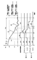
- FIG. 4 shows, in the present embodiment, fluctuations executed in parallel with engine start control and engine start control in two drive modes (first mode and second mode) selected during engine start operation. It is a figure for demonstrating suppression control.
- the horizontal axis represents time
- the vertical axis represents the rotational speed Ne of the engine 100 and the driving state of the actuator 232 and the motor 220 in the first mode and the second mode.
- a stop request for the engine 100 is generated and the combustion of the engine 100 is stopped.
- the rotational speed Ne of the engine 100 gradually decreases as indicated by a solid curve W0, and finally the rotation of the engine 100 stops.
- the first region (region 1) is a case where the rotational speed Ne of the engine 100 is higher than the second reference value ⁇ 2, for example, in a state where a restart request is generated at a point P0 in FIG. is there.
- This region 1 is a region where the engine 100 can be started without using the starter 200 by fuel injection and ignition operation because the rotational speed Ne of the engine 100 is sufficiently high. That is, region 1 is a region where engine 100 can return independently. Therefore, in region 1, driving of starter 200 is prohibited.
- the second reference value ⁇ 2 may be limited by the maximum rotation speed of the motor 220.
- the second region (region 2) is a case where the rotational speed Ne of the engine 100 is between the first reference value ⁇ 1 and the second reference value ⁇ 2, and a restart request is made at a point P1 in FIG. It is as if it was created.
- This region 2 is a region where the engine 100 cannot return independently but the rotational speed Ne of the engine 100 is relatively high. In this region, as described with reference to FIG. 3, the rotation mode (second mode) is selected.
- the starter control unit 304 When a restart request for the engine 100 is generated at time t2, the starter control unit 304 first drives the motor 220. As a result, the pinion gear 260 starts to rotate. Further, the fluctuation suppression control unit 306 performs fluctuation suppression control as the motor 220 is driven. Since fluctuation suppression control is as described above, detailed description thereof will not be repeated. By executing the fluctuation suppression control, sudden fluctuations in the rotational speed Ne of the engine 100 are suppressed.
- the actuator 232 is driven.
- the engagement between the ring gear 110 and the pinion gear 260 is completed by driving the actuator 232 at time t4, the execution of the fluctuation suppression control is released.
- the ring gear 110 and the pinion gear 260 are engaged, the engine 100 is cranked, and the rotational speed Ne of the engine 100 increases as indicated by a dashed curve W1. Thereafter, when engine 100 resumes self-sustaining operation, driving of actuator 232 and motor 220 is stopped.
- the third region (region 3) is a case where the rotational speed Ne of the engine 100 is lower than the first reference value ⁇ 1, for example, in a state where a restart request is generated at a point P2 in FIG. is there.
- This region 3 is a region where the rotation speed Ne of the engine 100 is low and the pinion gear 260 and the ring gear 110 can be engaged without synchronizing the pinion gear 260.
- the engagement mode is selected as described with reference to FIG.
- the starter control unit 304 first drives the actuator 232. Thereby, the pinion gear 260 is pushed out to the ring gear 110 side. When the engagement between the ring gear 110 and the pinion gear 260 is completed after the actuator 232 is driven at time t6, the motor 220 is driven. As a result, the engine 100 is cranked, and the rotational speed Ne of the engine 100 increases as indicated by a dashed curve W2. Thereafter, when engine 100 resumes self-sustaining operation, driving of actuator 232 and motor 220 is stopped.
- the conventional starter cannot rotate the engine 100 independently.
- the restart operation of the engine 100 is prohibited during the period (Tinh) from the speed (time t1 in FIG. 4) until the engine 100 stops (time t7 in FIG. 4)
- the engine 100 can be restarted. Thereby, it is possible to reduce a sense of incongruity caused by a delay in engine restart for the driver.
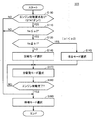
- FIG. 5 is a flowchart for illustrating the details of the operation mode setting control process executed by starter control unit 304 of ECU 300 in the present embodiment.
- the flowchart shown in FIG. 5 is realized by executing a program stored in advance in the memory of ECU 300 at a predetermined cycle. Alternatively, for some steps, it is also possible to construct dedicated hardware (electronic circuit) and realize processing.
- step (hereinafter, step is abbreviated as S) 100 starter control unit 304 determines whether or not there is a request for starting engine 100.
- starter control unit 304 does not need to start engine 100, so the process proceeds to S190 to select the standby mode.
- starter control unit 304 next determines whether rotation speed Ne of engine 100 is equal to or smaller than second reference value ⁇ 2. Determine.
- rotation speed Ne of engine 100 is greater than second reference value ⁇ 2 (NO in S110), this corresponds to region 1 in FIG. 4 where engine 100 can return independently, and starter control unit 304 performs the process. Proceeding to S190, the standby mode is selected.
- starter control unit 304 determines whether rotation speed Ne of engine 100 is equal to or smaller than first reference value ⁇ 1. Determine.
- the starter control unit 304 determines whether or not the engine 100 has been started in S180.
- the determination of the completion of the start of the engine 100 is made, for example, by determining whether or not the engine rotation speed is greater than a threshold value ⁇ indicating a self-sustained operation after a predetermined time has elapsed from the start of driving the motor 220. Good.
- ECU 300 selects all drive modes in S170. As a result, the actuator 232 is driven, the pinion gear 260 and the ring gear 110 are engaged, and the engine 100 is cranked.
- FIG. 6 is a flowchart for illustrating the details of the process of the fluctuation suppression control executed by fluctuation suppression control unit 306 of ECU 300 in the present embodiment.
- the flowchart shown in FIG. 6 is realized by executing a program stored in advance in the memory of ECU 300 at a predetermined cycle. Alternatively, for some steps, it is also possible to construct dedicated hardware (electronic circuit) and realize processing.
- fluctuation suppression control unit 306 determines whether or not there is a request for starting engine 100.
- the fluctuation suppression control unit 306 determines that the full drive mode is selected when both the motor 220 and the actuator 232 are operating, for example. Further, for example, when the motor 220 is operating with the actuator 232 stopped operating, or when both the motor 220 and the actuator 232 are operating stopped, the fluctuation suppression control unit 306 It is determined that the drive mode is not selected.
- the fluctuation suppression control unit 306 executes fluctuation suppression control. That is, the fluctuation suppression control unit 306 suppresses fluctuations in the load of the engine 100 by maintaining the operating state of at least one of the engine 100, the alternator 132, and the air conditioner compressor 134.
- the fluctuation suppression control unit 306 ends this process.
- the engine 100 when the rotation mode is selected in response to a start request of engine 100, the engine 100 is controlled so as to suppress fluctuations in the load of engine 100 before the time point when actuator 232 is operated.
- the rotational speed Nm of the motor 220 cannot be synchronized with the rotational speed Ne of the engine 100 due to the fluctuation of the rotational speed Ne of the engine 100 during driving of the motor 220 when the rotational mode is selected. can do. That is, when the actuator 232 is operated after the motor 220 is driven, the rotational speed Ne of the engine 100 can be accurately predicted.
- the drive start timing of the motor 220 for synchronizing the rotational speed Ne of the engine 100 and the rotational speed Nm of the motor 220 can be accurately set. Therefore, it is possible to provide an engine starter and an engine start method that suppress deterioration of engine startability.
- the operating state of the device (the air conditioner compressor 134 or the alternator 132) that varies the load of the engine 100 is maintained from the first time after the start request of the engine 100 to the second time when the actuator 232 is operated. Since it can suppress that the load of the engine 100 fluctuates until the actuator 232 is actuated, it is possible to suppress deterioration in startability.
- the engine 100 is operated until the actuator 232 is operated. Since it can suppress that a load fluctuates, startability can be prevented from deteriorating.
- ECU 300 selects actuator one of the first mode and the second mode based on the rotational speed of engine 100 so that engine 100 is started. And the motor 220 are controlled. Thereby, an appropriate mode is selected according to the rotational speed of engine 100. Therefore, when the second mode is selected, engine 100 can be started more reliably.
Landscapes
- Engineering & Computer Science (AREA)
- Chemical & Material Sciences (AREA)
- Combustion & Propulsion (AREA)
- Mechanical Engineering (AREA)
- General Engineering & Computer Science (AREA)
- Control Of Vehicle Engines Or Engines For Specific Uses (AREA)
Abstract
Description
図1は、車両10の全体ブロック図である。図1を参照して、車両10は、エンジン100と、バッテリ120と、スタータ200と、制御装置(以下ECU(Electronic Control Unit)とも称する。)300と、リレーRY1,RY2とを備える。また、スタータ200は、モータ220と、アクチュエータ232と、連結部240と、出力部材250と、ピニオンギヤ260とを含む。また、アクチュエータ232は、プランジャ210とソレノイド230とを含む。 [Configuration of engine starter]
FIG. 1 is an overall block diagram of the
図3は、本実施の形態におけるスタータ200の動作モードの遷移を説明するための図である。本実施の形態におけるスタータ200の動作モードには、待機モード410、係合モード420、回転モード430、および全駆動モード440が含まれる。 [Description of starter operation mode]
FIG. 3 is a diagram for explaining the transition of the operation mode of
図5は、本実施の形態において、ECU300のスタータ制御部304で実行される動作モード設定制御処理の詳細を説明するためのフローチャートである。図5に示すフローチャートは、ECU300のメモリに予め格納されたプログラムを所定周期で実行することによって実現される。あるいは、一部のステップについては、専用のハードウェア(電子回路)を構築して処理を実現することも可能である。 [Description of operation mode setting control]
FIG. 5 is a flowchart for illustrating the details of the operation mode setting control process executed by
図6は、本実施の形態において、ECU300の変動抑制制御部306で実行される変動抑制制御の処理の詳細を説明するためのフローチャートである。図6に示すフローチャートは、ECU300のメモリに予め格納されたプログラムを所定周期で実行することによって実現される。あるいは、一部のステップについては、専用のハードウェア(電子回路)を構築して処理を実現することも可能である。 [Explanation of fluctuation suppression control]
FIG. 6 is a flowchart for illustrating the details of the process of the fluctuation suppression control executed by fluctuation
Claims (9)
- エンジンの始動装置であって、
前記エンジン(100)を始動させるスタータ(200)と、
前記エンジン(100)のクランク軸(111)に連結され、前記エンジン(100)の負荷を変動する機器(132,134)と、
前記スタータ(200)の制御装置(300)とを備え、
前記スタータ(200)は、
前記エンジン(100)の前記クランク軸(111)に連結された第1のギヤ(110)と係合可能な第2のギヤ(260)と、
駆動状態において、前記第2のギヤ(260)を前記第1のギヤ(110)と係合する位置まで移動させるアクチュエータ(232)と、
前記第2のギヤ(260)を回転させるモータ(220)とを含み、
前記制御装置(300)は、前記アクチュエータ(232)および前記モータ(220)の各々を個別に駆動可能であり、
前記制御装置(300)は、前記アクチュエータ(232)の駆動に先立って前記モータ(220)を駆動させる回転モードを有し、
前記回転モードの実行時に、前記アクチュエータ(232)の駆動より前に前記エンジン(100)および前記機器(132,134)の負荷変動を抑制する、エンジンの始動装置。 An engine starter,
A starter (200) for starting the engine (100);
Devices (132, 134) connected to the crankshaft (111) of the engine (100) and changing the load of the engine (100);
A control device (300) for the starter (200),
The starter (200)
A second gear (260) engageable with a first gear (110) coupled to the crankshaft (111) of the engine (100);
An actuator (232) for moving the second gear (260) to a position engaged with the first gear (110) in a driving state;
A motor (220) for rotating the second gear (260),
The controller (300) can individually drive each of the actuator (232) and the motor (220),
The controller (300) has a rotation mode for driving the motor (220) prior to driving the actuator (232),
An engine starter that suppresses load fluctuations of the engine (100) and the devices (132, 134) prior to driving of the actuator (232) during execution of the rotation mode. - 前記制御装置(300)は、前記第1のギヤ(110)と前記第2のギヤ(260)との係合が完了した場合に前記負荷の変動の抑制を解除する、請求の範囲第1項に記載のエンジンの始動装置。 The said control apparatus (300) cancels | releases suppression of the fluctuation | variation of the said load, when engagement with the said 1st gear (110) and the said 2nd gear (260) is completed. The engine starter described in 1.
- 前記機器は、エアコンディショナコンプレッサ(134)およびオルタネータ(132)のうちの少なくともいずれか一方を含み、
前記制御装置(300)は、前記始動要求後の第1時点から前記アクチュエータ(232)を作動させる第2時点までの間前記機器(132,134)の作動状態を保持する、請求の範囲第1項に記載のエンジンの始動装置。 The device includes at least one of an air conditioner compressor (134) and an alternator (132),
The said control apparatus (300) maintains the operating state of the said apparatus (132,134) from the 1st time after the said start request | requirement to the 2nd time which operates the said actuator (232). The engine starting device according to the item. - 前記制御装置(300)は、前記始動要求後の第1時点から前記アクチュエータ(232)を作動させる第2時点までの間前記エンジン(100)の作動状態を保持する、請求の範囲第1項に記載のエンジンの始動装置。 The said control apparatus (300) maintains the operating state of the said engine (100) from the 1st time after the said start request | requirement to the 2nd time which operates the said actuator (232). The engine starting device as described.
- 前記制御装置(300)は、前記始動要求後の第1時点から前記アクチュエータ(232)を作動させる第2時点までの間前記エンジン(100)の負荷の変動を禁止するように前記エンジン(100)および前記機器(132,134)のうちのいずれか一方を制御する、請求の範囲第1項に記載のエンジンの始動装置。 The controller (300) controls the engine (100) so as to prohibit a change in the load of the engine (100) from a first time after the start request to a second time to operate the actuator (232). 2. The engine starting device according to claim 1, wherein the engine starting device controls one of said devices (132, 134).
- 前記機器は、エアコンディショナコンプレッサ(134)およびオルタネータ(132)のうちの少なくともいずれか一方を含み、
前記制御装置(300)は、前記始動要求後の第1時点から前記アクチュエータ(232)を作動させる第2時点までの間前記機器の作動を禁止する、請求の範囲第5項に記載のエンジンの始動装置。 The device includes at least one of an air conditioner compressor (134) and an alternator (132),
The engine according to claim 5, wherein the control device (300) prohibits the operation of the device from a first time after the start request to a second time when the actuator (232) is operated. Starter. - 前記制御装置(300)は、前記始動要求後の第1時点から前記アクチュエータ(232)を作動させる第2時点までの間前記エンジン(100)に対する制御値の変化を禁止する、請求の範囲第5項に記載のエンジンの始動装置。 The control device (300) prohibits a change in a control value for the engine (100) from a first time after the start request to a second time at which the actuator (232) is operated. The engine starting device according to the item.
- 前記制御装置(300)は、前記エンジン(100)の回転速度に基づいて複数の制御モードのうちのいずれか一つを選択して前記エンジン(100)が始動するように前記アクチュエータ(232)と前記モータ(220)とを制御し、
前記複数の制御モードは、前記回転モードの実行後に前記第1のギヤ(110)に向けて前記第2のギヤ(260)が移動するように前記アクチュエータ(232)を作動させるための第1制御モードと、前記アクチュエータ(232)の作動を開始した後に前記モータ(220)を作動させるための第2制御モードとを含む、請求の範囲第1項に記載のエンジンの始動装置。 The controller (300) selects the actuator (232) and starts the engine (100) by selecting any one of a plurality of control modes based on the rotational speed of the engine (100). Controlling the motor (220);
The plurality of control modes include a first control for operating the actuator (232) so that the second gear (260) moves toward the first gear (110) after execution of the rotation mode. The engine starter according to claim 1, comprising a mode and a second control mode for operating the motor (220) after starting the operation of the actuator (232). - エンジンの始動方法であって、
前記エンジンには、前記エンジン(100)を始動させるスタータ(200)と、前記エンジン(100)のクランク軸(111)に連結され、前記エンジン(100)の負荷を変動する機器(132,134)と、スタータ(200)の制御装置(300)とが設けられ、
前記スタータ(200)は、前記エンジン(100)の前記クランク軸(111)に連結された第1のギヤ(110)と係合可能な第2のギヤ(260)と、駆動状態において、前記第2のギヤ(260)を前記第1のギヤ(110)と係合する位置まで移動させるアクチュエータ(232)と、前記第2のギヤ(260)を回転させるモータ(220)とを含み、
前記アクチュエータ(232)および前記モータ(220)の各々は、個別に駆動可能であり、
前記始動方法は、前記アクチュエータ(232)の駆動に先立って前記モータ(220)を駆動させる回転モードで前記アクチュエータ(232)および前記モータ(220)を駆動するステップと、
前記回転モードの実行時に、前記アクチュエータ(232)の駆動より前に前記エンジン(100)および前記機器(132,134)の負荷変動を抑制するステップとを備える、エンジンの始動方法。 An engine starting method,
The engine is connected to a starter (200) for starting the engine (100) and a crankshaft (111) of the engine (100), and devices (132, 134) that vary the load of the engine (100). And a control device (300) of the starter (200),
The starter (200) includes a second gear (260) that can be engaged with a first gear (110) connected to the crankshaft (111) of the engine (100), and the first gear (260) in a driving state. An actuator (232) that moves the second gear (260) to a position that engages the first gear (110); and a motor (220) that rotates the second gear (260);
Each of the actuator (232) and the motor (220) can be individually driven,
The starting method includes driving the actuator (232) and the motor (220) in a rotation mode in which the motor (220) is driven prior to driving the actuator (232);
And a step of suppressing load fluctuations of the engine (100) and the devices (132, 134) before driving the actuator (232) when the rotation mode is executed.
Priority Applications (5)
| Application Number | Priority Date | Filing Date | Title |
|---|---|---|---|
| US13/144,999 US8573174B2 (en) | 2010-07-16 | 2010-07-16 | Engine starting device and engine starting method |
| CN2010800302139A CN102472230B (en) | 2010-07-16 | 2010-07-16 | Engine starting device and engine starting method |
| JP2011544530A JP5056988B2 (en) | 2010-07-16 | 2010-07-16 | Engine starter and engine start method |
| PCT/JP2010/062092 WO2012008050A1 (en) | 2010-07-16 | 2010-07-16 | Engine starting device and engine starting method |
| EP10844306.0A EP2514960A4 (en) | 2010-07-16 | 2010-07-16 | Engine starting device and engine starting method |
Applications Claiming Priority (1)
| Application Number | Priority Date | Filing Date | Title |
|---|---|---|---|
| PCT/JP2010/062092 WO2012008050A1 (en) | 2010-07-16 | 2010-07-16 | Engine starting device and engine starting method |
Publications (1)
| Publication Number | Publication Date |
|---|---|
| WO2012008050A1 true WO2012008050A1 (en) | 2012-01-19 |
Family
ID=45469074
Family Applications (1)
| Application Number | Title | Priority Date | Filing Date |
|---|---|---|---|
| PCT/JP2010/062092 WO2012008050A1 (en) | 2010-07-16 | 2010-07-16 | Engine starting device and engine starting method |
Country Status (5)
| Country | Link |
|---|---|
| US (1) | US8573174B2 (en) |
| EP (1) | EP2514960A4 (en) |
| JP (1) | JP5056988B2 (en) |
| CN (1) | CN102472230B (en) |
| WO (1) | WO2012008050A1 (en) |
Cited By (1)
| Publication number | Priority date | Publication date | Assignee | Title |
|---|---|---|---|---|
| US9109567B2 (en) | 2010-07-16 | 2015-08-18 | Toyota Jidosha Kabushiki Kaisha | Starter control device, starter control method, and engine starting device |
Families Citing this family (12)
| Publication number | Priority date | Publication date | Assignee | Title |
|---|---|---|---|---|
| CN102047686B (en) | 2008-04-07 | 2013-10-16 | 美国高思公司 | Wireless earphone that transitions between wireless networks |
| JP5316715B2 (en) | 2010-07-16 | 2013-10-16 | トヨタ自動車株式会社 | Starter control device, starter control method, and engine starter |
| WO2012008046A1 (en) * | 2010-07-16 | 2012-01-19 | トヨタ自動車株式会社 | Engine starting device and vehicle mounted with same |
| EP2573372A4 (en) * | 2011-03-08 | 2014-07-02 | Toyota Motor Co Ltd | Control device and control method for engine, engine start device, and vehicle |
| US8695553B2 (en) * | 2011-03-25 | 2014-04-15 | Toyota Jidosha Kabushiki Kaisha | Control device and control method for starter, and vehicle |
| US8860536B2 (en) * | 2011-11-15 | 2014-10-14 | Remy Technologies, Llc | Starter system |
| DE102012210890B4 (en) * | 2012-06-26 | 2021-03-18 | Seg Automotive Germany Gmbh | Turning device and method for assembling a turning device |
| DE102012015034A1 (en) * | 2012-07-31 | 2014-02-27 | Andreas Stihl Ag & Co. Kg | Method for switching off a speed limitation in an internal combustion engine |
| DE102013226999B4 (en) * | 2013-12-20 | 2020-06-04 | Seg Automotive Germany Gmbh | Method for engaging an axially displaceable starter pinion of a starting device in a ring gear of an internal combustion engine |
| US9481236B2 (en) | 2014-03-13 | 2016-11-01 | GM Global Technology Operations LLC | Powertrain for a vehicle |
| US9657705B2 (en) * | 2014-03-13 | 2017-05-23 | GM Global Technology Operations LLC | Powertrain for a vehicle and an electromechanical apparatus coupleable to an engine |
| DE112016002139B4 (en) * | 2015-05-12 | 2021-08-12 | Mitsubishi Electric Corporation | Engine generator, machine starting device and method for machine starting control |
Citations (4)
| Publication number | Priority date | Publication date | Assignee | Title |
|---|---|---|---|---|
| JP2001073911A (en) * | 1999-08-31 | 2001-03-21 | Denso Corp | Clutch control device |
| JP2002115631A (en) * | 2000-10-12 | 2002-04-19 | Toyota Motor Corp | Starting device for internal combustion engine |
| JP2005030348A (en) * | 2003-07-10 | 2005-02-03 | Nissan Motor Co Ltd | Accessory drive control device of internal combustion engine |
| EP2159410A2 (en) * | 2008-09-02 | 2010-03-03 | Denso Corporation | System for restarting internal combustion engine when engine restart request occurs |
Family Cites Families (12)
| Publication number | Priority date | Publication date | Assignee | Title |
|---|---|---|---|---|
| JP4199456B2 (en) | 2000-03-10 | 2008-12-17 | 株式会社日立製作所 | Automatic transmission and its control device |
| JP2002285942A (en) | 2001-03-27 | 2002-10-03 | Honda Motor Co Ltd | Starting device of engine |
| JP4214401B2 (en) * | 2004-05-18 | 2009-01-28 | 株式会社デンソー | Engine automatic stop / restart device |
| JP4889249B2 (en) * | 2005-07-05 | 2012-03-07 | 日産自動車株式会社 | Engine starter protection method and engine starter protection device |
| DE102006011644A1 (en) | 2006-03-06 | 2007-09-13 | Robert Bosch Gmbh | Device having a first gear part for meshing in a second gear part, in particular starting device with a pinion for meshing in a ring gear of an internal combustion engine and method for operating such a device |
| JP2008163818A (en) | 2006-12-28 | 2008-07-17 | Hitachi Ltd | Starter |
| JP5251751B2 (en) | 2008-07-04 | 2013-07-31 | トヨタ自動車株式会社 | Starter for internal combustion engine |
| DE102008041037A1 (en) * | 2008-08-06 | 2010-02-11 | Robert Bosch Gmbh | Method and device of a control for a start-stop operation of an internal combustion engine |
| JP4737571B2 (en) * | 2008-09-08 | 2011-08-03 | 株式会社デンソー | Engine starter |
| JP4631962B2 (en) | 2008-11-11 | 2011-02-16 | トヨタ自動車株式会社 | Engine start control device |
| JP2010229882A (en) | 2009-03-27 | 2010-10-14 | Hitachi Automotive Systems Ltd | Vehicle control device and idling stop system |
| WO2012011167A1 (en) * | 2010-07-21 | 2012-01-26 | トヨタ自動車株式会社 | Engine starting device and engine starting method |
-
2010
- 2010-07-16 CN CN2010800302139A patent/CN102472230B/en not_active Expired - Fee Related
- 2010-07-16 EP EP10844306.0A patent/EP2514960A4/en not_active Withdrawn
- 2010-07-16 US US13/144,999 patent/US8573174B2/en not_active Expired - Fee Related
- 2010-07-16 WO PCT/JP2010/062092 patent/WO2012008050A1/en active Application Filing
- 2010-07-16 JP JP2011544530A patent/JP5056988B2/en not_active Expired - Fee Related
Patent Citations (4)
| Publication number | Priority date | Publication date | Assignee | Title |
|---|---|---|---|---|
| JP2001073911A (en) * | 1999-08-31 | 2001-03-21 | Denso Corp | Clutch control device |
| JP2002115631A (en) * | 2000-10-12 | 2002-04-19 | Toyota Motor Corp | Starting device for internal combustion engine |
| JP2005030348A (en) * | 2003-07-10 | 2005-02-03 | Nissan Motor Co Ltd | Accessory drive control device of internal combustion engine |
| EP2159410A2 (en) * | 2008-09-02 | 2010-03-03 | Denso Corporation | System for restarting internal combustion engine when engine restart request occurs |
Non-Patent Citations (1)
| Title |
|---|
| See also references of EP2514960A4 * |
Cited By (1)
| Publication number | Priority date | Publication date | Assignee | Title |
|---|---|---|---|---|
| US9109567B2 (en) | 2010-07-16 | 2015-08-18 | Toyota Jidosha Kabushiki Kaisha | Starter control device, starter control method, and engine starting device |
Also Published As
| Publication number | Publication date |
|---|---|
| EP2514960A4 (en) | 2013-05-15 |
| EP2514960A1 (en) | 2012-10-24 |
| CN102472230B (en) | 2013-07-10 |
| JP5056988B2 (en) | 2012-10-24 |
| JPWO2012008050A1 (en) | 2013-09-05 |
| US20130099507A1 (en) | 2013-04-25 |
| US8573174B2 (en) | 2013-11-05 |
| CN102472230A (en) | 2012-05-23 |
Similar Documents
| Publication | Publication Date | Title |
|---|---|---|
| JP5056988B2 (en) | Engine starter and engine start method | |
| JP5105032B2 (en) | Starter control device and control method, and vehicle | |
| WO2012011167A1 (en) | Engine starting device and engine starting method | |
| JP5316715B2 (en) | Starter control device, starter control method, and engine starter | |
| JP5170347B1 (en) | Engine starter and control method | |
| JP5224005B2 (en) | Starter control device, starter control method, and engine starter | |
| JP5321744B2 (en) | Engine starter and vehicle equipped with the same | |
| JP5321745B2 (en) | Engine starter and vehicle equipped with the same | |
| JP5321746B2 (en) | Starter control device and starter control method | |
| JP5644843B2 (en) | Vehicle control device | |
| JP5288070B2 (en) | ENGINE CONTROL DEVICE AND CONTROL METHOD, AND VEHICLE | |
| JP5316734B2 (en) | Starter control device and control method, and vehicle | |
| JP2012021494A (en) | Starting device of engine and vehicle mounted therewith | |
| JP5454402B2 (en) | Starter control device | |
| JP2012021495A (en) | Engine starting device and vehicle with the same loaded | |
| JP2012021496A (en) | Engine starting device and vehicle with the same loaded |
Legal Events
| Date | Code | Title | Description |
|---|---|---|---|
| WWE | Wipo information: entry into national phase |
Ref document number: 201080030213.9 Country of ref document: CN |
|
| WWE | Wipo information: entry into national phase |
Ref document number: 13144999 Country of ref document: US |
|
| WWE | Wipo information: entry into national phase |
Ref document number: 2010844306 Country of ref document: EP |
|
| WWE | Wipo information: entry into national phase |
Ref document number: 2011544530 Country of ref document: JP |
|
| 121 | Ep: the epo has been informed by wipo that ep was designated in this application |
Ref document number: 10844306 Country of ref document: EP Kind code of ref document: A1 |
|
| NENP | Non-entry into the national phase |
Ref country code: DE |