WO2012008014A1 - 随伴水濃縮システムおよび随伴水濃縮方法 - Google Patents
随伴水濃縮システムおよび随伴水濃縮方法 Download PDFInfo
- Publication number
- WO2012008014A1 WO2012008014A1 PCT/JP2010/061804 JP2010061804W WO2012008014A1 WO 2012008014 A1 WO2012008014 A1 WO 2012008014A1 JP 2010061804 W JP2010061804 W JP 2010061804W WO 2012008014 A1 WO2012008014 A1 WO 2012008014A1
- Authority
- WO
- WIPO (PCT)
- Prior art keywords
- water
- cooling
- accompanying
- concentration system
- evaporation method
- Prior art date
- Legal status (The legal status is an assumption and is not a legal conclusion. Google has not performed a legal analysis and makes no representation as to the accuracy of the status listed.)
- Ceased
Links
Images


Classifications
-
- C—CHEMISTRY; METALLURGY
- C02—TREATMENT OF WATER, WASTE WATER, SEWAGE, OR SLUDGE
- C02F—TREATMENT OF WATER, WASTE WATER, SEWAGE, OR SLUDGE
- C02F1/00—Treatment of water, waste water, or sewage
- C02F1/02—Treatment of water, waste water, or sewage by heating
- C02F1/04—Treatment of water, waste water, or sewage by heating by distillation or evaporation
- C02F1/048—Purification of waste water by evaporation
-
- B—PERFORMING OPERATIONS; TRANSPORTING
- B01—PHYSICAL OR CHEMICAL PROCESSES OR APPARATUS IN GENERAL
- B01D—SEPARATION
- B01D3/00—Distillation or related exchange processes in which liquids are contacted with gaseous media, e.g. stripping
- B01D3/007—Energy recuperation; Heat pumps
-
- C—CHEMISTRY; METALLURGY
- C02—TREATMENT OF WATER, WASTE WATER, SEWAGE, OR SLUDGE
- C02F—TREATMENT OF WATER, WASTE WATER, SEWAGE, OR SLUDGE
- C02F1/00—Treatment of water, waste water, or sewage
- C02F1/44—Treatment of water, waste water, or sewage by dialysis, osmosis or reverse osmosis
- C02F1/441—Treatment of water, waste water, or sewage by dialysis, osmosis or reverse osmosis by reverse osmosis
-
- C—CHEMISTRY; METALLURGY
- C02—TREATMENT OF WATER, WASTE WATER, SEWAGE, OR SLUDGE
- C02F—TREATMENT OF WATER, WASTE WATER, SEWAGE, OR SLUDGE
- C02F1/00—Treatment of water, waste water, or sewage
- C02F1/008—Control or steering systems not provided for elsewhere in subclass C02F
-
- C—CHEMISTRY; METALLURGY
- C02—TREATMENT OF WATER, WASTE WATER, SEWAGE, OR SLUDGE
- C02F—TREATMENT OF WATER, WASTE WATER, SEWAGE, OR SLUDGE
- C02F1/00—Treatment of water, waste water, or sewage
- C02F1/02—Treatment of water, waste water, or sewage by heating
- C02F1/04—Treatment of water, waste water, or sewage by heating by distillation or evaporation
- C02F1/16—Treatment of water, waste water, or sewage by heating by distillation or evaporation using waste heat from other processes
-
- C—CHEMISTRY; METALLURGY
- C02—TREATMENT OF WATER, WASTE WATER, SEWAGE, OR SLUDGE
- C02F—TREATMENT OF WATER, WASTE WATER, SEWAGE, OR SLUDGE
- C02F2103/00—Nature of the water, waste water, sewage or sludge to be treated
- C02F2103/10—Nature of the water, waste water, sewage or sludge to be treated from quarries or from mining activities
-
- C—CHEMISTRY; METALLURGY
- C02—TREATMENT OF WATER, WASTE WATER, SEWAGE, OR SLUDGE
- C02F—TREATMENT OF WATER, WASTE WATER, SEWAGE, OR SLUDGE
- C02F2103/00—Nature of the water, waste water, sewage or sludge to be treated
- C02F2103/18—Nature of the water, waste water, sewage or sludge to be treated from the purification of gaseous effluents
-
- C—CHEMISTRY; METALLURGY
- C02—TREATMENT OF WATER, WASTE WATER, SEWAGE, OR SLUDGE
- C02F—TREATMENT OF WATER, WASTE WATER, SEWAGE, OR SLUDGE
- C02F2103/00—Nature of the water, waste water, sewage or sludge to be treated
- C02F2103/34—Nature of the water, waste water, sewage or sludge to be treated from industrial activities not provided for in groups C02F2103/12 - C02F2103/32
- C02F2103/36—Nature of the water, waste water, sewage or sludge to be treated from industrial activities not provided for in groups C02F2103/12 - C02F2103/32 from the manufacture of organic compounds
- C02F2103/365—Nature of the water, waste water, sewage or sludge to be treated from industrial activities not provided for in groups C02F2103/12 - C02F2103/32 from the manufacture of organic compounds from petrochemical industry (e.g. refineries)
-
- C—CHEMISTRY; METALLURGY
- C02—TREATMENT OF WATER, WASTE WATER, SEWAGE, OR SLUDGE
- C02F—TREATMENT OF WATER, WASTE WATER, SEWAGE, OR SLUDGE
- C02F2209/00—Controlling or monitoring parameters in water treatment
- C02F2209/02—Temperature
-
- C—CHEMISTRY; METALLURGY
- C02—TREATMENT OF WATER, WASTE WATER, SEWAGE, OR SLUDGE
- C02F—TREATMENT OF WATER, WASTE WATER, SEWAGE, OR SLUDGE
- C02F2209/00—Controlling or monitoring parameters in water treatment
- C02F2209/10—Solids, e.g. total solids [TS], total suspended solids [TSS] or volatile solids [VS]
-
- C—CHEMISTRY; METALLURGY
- C02—TREATMENT OF WATER, WASTE WATER, SEWAGE, OR SLUDGE
- C02F—TREATMENT OF WATER, WASTE WATER, SEWAGE, OR SLUDGE
- C02F2209/00—Controlling or monitoring parameters in water treatment
- C02F2209/40—Liquid flow rate
-
- Y—GENERAL TAGGING OF NEW TECHNOLOGICAL DEVELOPMENTS; GENERAL TAGGING OF CROSS-SECTIONAL TECHNOLOGIES SPANNING OVER SEVERAL SECTIONS OF THE IPC; TECHNICAL SUBJECTS COVERED BY FORMER USPC CROSS-REFERENCE ART COLLECTIONS [XRACs] AND DIGESTS
- Y02—TECHNOLOGIES OR APPLICATIONS FOR MITIGATION OR ADAPTATION AGAINST CLIMATE CHANGE
- Y02W—CLIMATE CHANGE MITIGATION TECHNOLOGIES RELATED TO WASTEWATER TREATMENT OR WASTE MANAGEMENT
- Y02W10/00—Technologies for wastewater treatment
- Y02W10/30—Wastewater or sewage treatment systems using renewable energies
- Y02W10/37—Wastewater or sewage treatment systems using renewable energies using solar energy
Definitions
- the present invention relates to an accompanying water concentrating system and an accompanying water concentrating method, and more particularly to an accompanying water concentrating system and an accompanying water concentrating system characterized by a circulating system of cooling water required when processing accompanying water generated during coal mining by an evaporation method. Regarding the method.
- coal seam methane gas existing in the coal seam has attracted attention as a new natural gas. Since coal seam methane gas is dissolved in the accompanying water contained in the coal seam, it is obtained by separating the methane gas from the accompanying water after pumping up the accompanying water with a screw pump installed in the well (see Non-Patent Document 1).
- the method of temporarily storing the accompanying water in the reservoir causes a problem that a large reservoir is required as mining of the coal bed methane gas continues, making it difficult to continuously implement the coal bed methane gas mining project.
- concentration is reduced by using a reverse osmosis membrane device
- the required power of the reverse osmosis membrane device increases as the salt concentration increases, so a high concentration rate can be obtained in terms of processing costs. It becomes difficult and a similar problem occurs.
- the present invention has been made based on the above-mentioned matters, and its purpose is to reduce the accompanying water generated when obtaining coal-bed methane gas, and to use the accompanying method using an evaporation method concentrating device capable of reducing the amount of concentrated water stored in the reservoir.
- an accompanying water concentration system and an accompanying water concentration method that do not require special equipment for treating cooling water after being used in an evaporation method concentration apparatus are provided.
- the first invention is an accompanying water concentration system including an evaporation method concentrating device for concentrating accompanying water discharged together with coal bed gas from a coal bed, wherein the evaporation method concentrating device is provided.
- the cooling system for cooling includes an indirect heat exchanger for cooling the evaporation method concentrator, a cooling water supply means for taking the cooling water used for cooling from a well or a reservoir, and supplying the cooling water to the indirect heat exchanger, and the indirect heat.
- the second invention is an accompanying water concentration system comprising an evaporation method concentrating device for concentrating accompanying water discharged together with coal bed gas from a coal bed, wherein the evaporation method concentrating device is provided.
- the cooling system for cooling includes an indirect heat exchanger for cooling the evaporation method concentrator, a cooling water supply means for taking cooling water used for cooling from a well or a reservoir, and supplying the cooling water to the indirect heat exchanger, It shall be comprised with the closed circuit which consists of a waste warm water return means which returns waste warm water to the said well or the said pond.
- the third invention is characterized in that, in the first or second invention, a power generation facility capable of utilizing waste heat as a heat source of the evaporation method concentrator and a waste heat recovery boiler are provided.
- a fourth invention is the method according to any one of the first to third inventions, further comprising a reverse osmosis membrane type concentrating device in front of the evaporation method concentrating device, and the concentrated water from the reverse osmosis membrane type concentrating device It is characterized in that it is supplied as raw water for the evaporation method concentrator.
- 5th invention is the water temperature measurement means which measures the water temperature of the said waste warm water discharged
- a control device for controlling the flow rate of the cooling water supply means and / or the flow rate of the waste warm water return means so that the temperature of the waste hot water becomes equal to or lower than a predetermined value set in advance.
- a sixth invention is the fifth invention, wherein, in order to control the flow rate of the cooling water supply means and / or the flow rate of the waste warm water return means, the cooling water supply means according to the output of the control device. And / or using the inverter which outputs motive power to the said waste warm water return means.
- the seventh invention is characterized in that, in any one of the first to sixth inventions, a cooling means for cooling the cooling water is provided in a previous stage to be supplied to the evaporation method concentrating device.
- an eighth invention is characterized in that, in any one of the first to seventh inventions, a predetermined water depth range is provided in the pond and the cooling water intake is provided below the water depth range.
- the ninth invention is characterized in that, in any one of the first to eighth inventions, an electric immersion pump is used as a device for taking the cooling water from the well.
- a tenth aspect of the invention is based on the ninth aspect of the invention based on the fine particle detector that detects the amount of solid fine particles in the accompanying water solution and the solid fine particle signal that is the output of the fine particle detector.
- an electric immersion pump control device for stopping the electric immersion pump or reducing the suction flow rate.
- the eleventh invention is based on the ninth invention, based on an in-liquid bubble detector that detects an amount of bubbles in the liquid of the accompanying water, and a bubble signal that is an output of the in-liquid bubble detector.
- An electric immersion pump control device that stops the electric immersion pump or reduces the suction flow rate is provided.
- the twelfth invention is an accompanying water concentration method by an evaporation method concentrating device for concentrating the accompanying water discharged from the coal seam together with the coal bed gas, wherein the cooling step for cooling the evaporation method concentrating device is used for cooling.
- a cooling water supply process for taking cooling water from a well or a reservoir and supplying it to an indirect heat exchanger that cools the evaporative concentration apparatus, and a waste hot water returning process for returning the waste warm water after cooling to the well or the reservoir. Shall have.
- the volume of the accompanying water can be reduced by the evaporation method, so that the accompanying water can be easily discarded.
- the evaporation method concentrator taken from a well or pond is returned to the source, no cooling or chemical treatment is required. Running costs can be reduced.
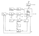
- FIG. 1 is a system configuration diagram showing a first embodiment of an accompanying water concentration system of the present invention
- FIG. 2 is a schematic cross-sectional view showing a water intake portion of a pond in the first embodiment of the accompanying water concentration system of the present invention. It is.
- the accompanying water which becomes unnecessary after taking the coal bed gas and separating the coal bed gas becomes the raw water 10 for the accompanying water concentration system.
- the raw water 10 flows into the reverse osmosis membrane type concentrator 12 and is separated into fresh water 14 and concentrated water 16.
- the use of the fresh water 14 is not specified, it can be used as river discharge or irrigation water because the salt concentration is low.
- the concentrated water 16 of the reverse osmosis membrane type concentrator 12 is supplied to an evaporation method concentrator 18.
- the evaporation method concentrator 18 is supplied with steam 24 from an exhaust heat recovery boiler 26 that converts exhaust heat of the exhaust gas 22 of the power generation facility 20 into steam 24. Indirect heat that is provided in the evaporation method concentrator 18 using the heat energy of the steam 24 and cools the evaporation method concentrator 18 without changing the water quality of the cooling water 36 so as not to affect the groundwater layer.
- the concentrated water 16 of the reverse osmosis membrane type concentrator 12 is separated into fresh water 30 and highly concentrated water 32 by the exchanger 28.
- the highly concentrated water 32 having a high salt concentration cannot be used as river discharge or irrigation water, it is discarded in the pond 34 or supplied to a crystallization apparatus (not shown) for recovering valuable materials.
- the capacity of the basin 34 can be reduced or the crystallization apparatus (not shown) can be downsized.
- the cooling water 36 required by the indirect heat exchanger 28 is taken from the reservoir 34 by the cooling water supply means 38.
- the cooling water supply unit 38 may be specifically configured by an electric pump or the like, for example.
- the cooling means 42 for lowering the water temperature of the cooling water 36 is provided on the downstream side of the cooling water supply means 38, and the cooling water 36 whose water temperature has been lowered is supplied to the indirect heat exchanger 28.
- the cooling means 42 a method using a heat pump, a method of electronically cooling by a Peltier element, or a part of the cooling water 36 is vaporized by a spraying device or the like, and the remaining cooling water 36 is further cooled by the overheating.
- the cooling means 42 may not be provided.
- the cooling water 36 receives heat energy and becomes waste hot water 44.
- the waste hot water 44 is circulated to the reservoir 34 by the waste hot water return means 40 to form a closed circuit.
- the pond 34 has no restriction on the difference between the intake temperature and the disposal temperature, and therefore it is not necessary to provide a special cooling facility.
- the cooling water 36 When the cooling water 36 is taken from a pond, the water temperature fluctuates over time due to the effects of solar radiation and temperature. Even when the cooling water 36 is taken from the well, the time constant is larger than in the case of the pond, but the water temperature fluctuates with time.
- the concentration capacity of the indirect heat exchanger 28 is affected by the water temperature of the cooling water 36, this capacity can be evaluated by the water temperature of the waste hot water 44.
- the temperature of the waste hot water 44 is measured by the water temperature sensor 46 and given to the control device 50 as a water temperature signal 48.
- the control device 50 controls the flow rate of the cooling water supply means 38 or the flow rate of the waste hot water return means 40 based on the preset waste hot water temperature target value 52 and the water temperature signal 48, and the cooling capacity of the cooling means 42.
- control device 50 calculates the operating condition that minimizes the sum of the operating cost of the cooling water supply means 38 or the waste hot water return means 40 and the operating cost of the cooling means 42, and realizes the condition. Control of the cooling water supply means 38, the waste warm water return means 40, and the cooling means 42 is performed.
- These flow rates are controlled by outputting operation signals 60 and 64 from the control device 50 to the cooling water supply means inverter 54 or the waste hot water return means inverter 56, respectively, thereby pumping the cooling water supply means 38 and the waste hot water return means 40.
- the cooling water supply means power 62 and the waste hot water return means power 66 which are power to the electric motor or the like, are controlled. As compared with the case where a valve is used for the flow rate control, the pressure loss that is wasted can be reduced, and the running cost can be further reduced.
- the cooling means 42 When the cooling means 42 is not provided, only the cooling water supply means 38 or the waste hot water return means 40 is controlled by the control device 50. Even in this case, the flow rate of each means is controlled via the cooling water supply means inverter 54 or the waste hot water return means inverter 56 based on the waste warm water temperature signal 48 and the waste warm water temperature target value 52. The running cost can be reduced.
- FIG. 2 is a schematic view showing the intake portion of the pond in the first embodiment of the accompanying water concentration system of the present invention.
- FIG. 2 the same reference numerals as those shown in FIG.
- the cooling water 36 When the cooling water 36 is taken from the pond 34, the water near the water surface of the pond 34 is affected by solar radiation and temperature, so the water temperature is high. On the other hand, when water evaporates from the water surface of the pond 34, heat is removed as heat of vaporization, so that a physical phenomenon that lowers the water temperature also occurs simultaneously. In addition, when the air temperature around the pond is lower than the water temperature, heat escapes from the water surface to the air, so the water temperature decreases. The density of water varies with the water temperature and is maximum at about 4 ° C. Since there is no stirrer in the pond 34, water having a low water temperature generally moves toward the bottom of the pond 34.
- a water intake 70 for the cooling water 36 is provided at a location deeper than a predetermined water depth, and the cooling water 36 is taken. Thereby, the cooling water 36 whose water temperature is lower can be obtained.
- the volume of the accompanying water can be reduced by the evaporation method, so that the accompanying water can be easily discarded.
- cooling and chemical treatments are not required when returning the cooling water from the evaporative concentration device taken from the pond to the water source, so equipment costs and running costs are reduced compared to returning cooling water to rivers and seawater. Can be reduced.
- the cooling water is supplied from the reservoir 34.
- the reservoir 34 By taking water 36, it is possible to reduce the cost of pipe laying and the operating cost.
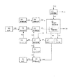
- FIG. 3 is a system configuration diagram showing a second embodiment of the accompanying water concentration system of the present invention.
- the same reference numerals as those shown in FIGS. 1 and 2 are the same parts, and detailed description thereof is omitted.
- the cooling water supply means 38 in the first embodiment is omitted.
- water can be taken in by the waste hot water returning means 40, and the cooling water supply means 38 can be omitted.
- the cooling water 36 is taken from the reservoir 34 by the waste warm water returning means 40, the water temperature in the waste hot water returning means 40 is increased, so that the viscosity resistance of the water is lowered and the running cost can be reduced.
- the waste warm water returning means 40 may be constituted by, for example, an electric pump or the like.
- FIG. 4 is a system configuration diagram showing a third embodiment of the accompanying water concentration system of the present invention. 4, the same reference numerals as those shown in FIG. 1 to FIG.
- the waste warm water returning means 40 in the first embodiment is omitted.
- the waste warm water returning means 40 in the first embodiment is omitted.
- FIG. 5 is a system configuration diagram showing a fourth embodiment of the accompanying water concentration system of the present invention. 5, the same reference numerals as those shown in FIG. 1 to FIG.
- the accompanying water which became unnecessary after taking water from the coal bed and separating the coal bed gas becomes the raw water 10 for the accompanying water concentration system.
- This raw water 10 flows into the reverse osmosis membrane type concentrator 12 and is separated into fresh water 14 and concentrated water 16.
- fresh water 14 is not specified, but it can be used as river discharge or irrigation water because of its low salt concentration.
- the concentrated water 16 of the reverse osmosis membrane type concentrator 12 is supplied to an evaporation method concentrator 18.
- the evaporation method concentrator 18 is supplied with steam 24 from an exhaust heat recovery boiler 26 that converts exhaust heat of the exhaust gas 22 of the power generation facility 20 into steam 24.
- the concentrated water 16 of the reverse osmosis membrane type concentrator 12 is separated into fresh water 30 and highly concentrated water 32 by an indirect heat exchanger 28 provided in the evaporation method concentrator 18.
- the highly concentrated water 32 having a high salt concentration cannot be used for discharge or irrigation, it is discarded in the pond 34 or supplied to a crystallization apparatus (not shown) for recovering valuable materials.
- the capacity of the basin 34 can be reduced or the crystallization apparatus (not shown) can be downsized.
- the cooling water 36 required by the indirect heat exchanger 28 is taken from the well 68 by the cooling water supply means 38 or the waste hot water return means 40. Since the well from which the coal seam gas is collected is generally located at a location far from the river or the ocean, the cooling water 36 can be taken from the well 68 to reduce the cost of piping installation and the operation cost.
- Well water taken from the well 68 is generally suitable as the cooling water 36 because the water temperature is generally stable and is not affected by temperature or solar radiation.
- the cooling means 42 is provided on the downstream side of the cooling water supply means 38, and the cooling water 36 with the water temperature lowered is supplied to the indirect heat exchanger 28.
- the cooling means 42 a method using a heat pump, a method of electronically cooling with a Peltier element, or a part of the cooling water 36 is vaporized by a spraying device or the like, and the remaining cooling water 36 is further cooled by the heat of vaporization.
- There are a method, a method using an absorption refrigerator, a method using cold heat previously stored in ice or the like with surplus power, and any of them may be used. If the water temperature of the cooling water 36 can be cooled by the well 68, the cooling means 42 need not be provided.
- the cooling water 36 receives heat energy and becomes waste hot water 44.
- the waste hot water 44 is circulated to the well 68 by the waste hot water returning means 40 to form a closed circuit.
- the well 68 has no restriction on the difference between the water intake temperature and the disposal temperature, and therefore there is no need to provide a special cooling facility. Further, since the cooling water 36 only changes in temperature in the indirect heat exchanger 28 and does not change in chemical properties, there is no problem even if it is circulated to the well 68 as the waste hot water 44.
- FIG. 5 shows a flow of returning the waste warm water 44 after taking water from the well 68 and using it for cooling to the well 68
- the waste warm water 44 may be returned to the reservoir 34.
- the concentration capacity of the indirect heat exchanger 28 is affected by the water temperature of the cooling water 36, and this capacity can be evaluated by the water temperature of the waste hot water 44.
- the temperature of the waste hot water 44 is measured by the water temperature sensor 46 and given to the control device 50 as a water temperature signal 48.
- the control device 50 controls the flow rate of the cooling water supply means 38 or the flow rate of the waste hot water return means 40 based on the preset waste hot water temperature target value 52 and the water temperature signal 48, and the cooling capacity of the cooling means 42. Control.
- the control device 50 calculates the operating condition that minimizes the sum of the operating cost of the cooling water supply means 38 or the waste hot water return means 40 and the operating cost of the cooling means 42, and realizes the condition. Control of the cooling water supply means 38, the waste warm water return means 40, and the cooling means 42 is performed.
- These flow rates are controlled by outputting operation signals 60 and 64 from the control device 50 to the cooling water supply means inverter 54 or the waste hot water return means inverter 56, respectively, thereby pumping the cooling water supply means 38 and the waste hot water return means 40.
- the cooling water supply means power 62 and the waste hot water return means power 66 which are power to the electric motor or the like, are controlled.
- the cooling means 42 When the cooling means 42 is not provided, only the cooling water supply means 38 or the waste hot water return means 40 is controlled by the control device 50. Even in this case, the flow rate of each means is controlled via the cooling water supply means inverter 54 or the waste hot water return means inverter 56 based on the waste warm water temperature signal 48 and the waste warm water temperature target value 52. The running cost can be reduced.
- the accompanying water volume can be reduced by the evaporation method, so that the accompanying water can be easily discarded.
- cooling and chemical treatment are not required when returning the cooling water from the evaporative concentration device taken from the well to the water source, so equipment costs and running costs are reduced compared to returning cooling water to rivers and seawater. Can be reduced.
- the cooling water is supplied from the well 68.
- the cooling water By taking water 36, it is possible to reduce the cost of pipe laying and the operating cost.
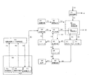
- FIG. 6 is a system configuration diagram showing a fifth embodiment of the accompanying water concentration system of the present invention.
- the same reference numerals as those shown in FIGS. 1 to 5 are the same parts, and detailed description thereof is omitted.
- an electric dipping pump 72 is used as the cooling water supply means 38 for taking the cooling water 36 from the well 68 of the coal seam in the fourth embodiment described above.
- the electric immersion pump 72 is used when pumping the accompanying water contained in the coal seam, the ratio of mechanical loss is reduced as compared with a screw pump conventionally used, and maintenance is facilitated. As a result, the running cost can be reduced.
- Examples of the solid matter that can be included in the accompanying water include coal powder, rock particles, sand particles, and the like, and when these particles become fine particles, they are likely to be mixed between the pump components and induce a failure.
- the submerged particle detector 74 that detects the amount of solid particulates in the accompanying water liquid, and the electric immersion pump 72 is stopped based on the detection signal of the submerged particle detector 74.
- an electric dipping pump control device 82 for reducing the suction flow rate.
- the suction flow rate of the electric dipping pump 72 is reduced or stopped to wait for these solid particulates to sink downward, and then pumped up. By starting the operation, it is possible to suppress the performance degradation of the electric immersion pump 72 and the like.
- the electric immersion pump 72 runs idle, resulting in a case where the performance deteriorates or the failure occurs in the worst case.
- the electric immersion pump 72 is provided below the well 68, so that time and cost are spent for lifting and maintenance.
- the submerged bubble detector 78 that detects the amount of bubbles in the liquid of the accompanying water, and the electric immersion pump 72 is stopped based on the detection signal of the submerged bubble detector 78, And an electric immersion pump controller 82 for reducing the suction flow rate.
- the same effect as that of the fourth embodiment described above can be obtained, and the electric immersion pump 72 is used instead of the screw pump. Therefore, the rate of mechanical loss is reduced, and maintenance is facilitated. As a result, the running cost can be reduced.
- the accompanying water since the in-liquid particle detector 74, the in-liquid bubble detector 78, and the electric immersion pump control device are provided, the accompanying water It is possible to suppress deterioration in performance or failure of the electric immersion pump 72 caused by solid fine particles or bubbles therein at an early stage. As a result, it is possible to reduce the time and cost spent for the lifting operation and maintenance of the electric immersion pump 72.
- the evaporation method concentrating device 18 to which the concentrated water 16 concentrated by the reverse osmosis membrane type concentrating device 12 is supplied has been described.
- the present invention is not limited to this.
- the evaporation method concentration apparatus 18 to which the accompanying water is directly supplied as the raw water 10 may be used.
Landscapes
- Chemical & Material Sciences (AREA)
- Life Sciences & Earth Sciences (AREA)
- Hydrology & Water Resources (AREA)
- Engineering & Computer Science (AREA)
- Environmental & Geological Engineering (AREA)
- Water Supply & Treatment (AREA)
- Organic Chemistry (AREA)
- Chemical Kinetics & Catalysis (AREA)
- Heat Treatment Of Water, Waste Water Or Sewage (AREA)
- Separation Using Semi-Permeable Membranes (AREA)
- Vaporization, Distillation, Condensation, Sublimation, And Cold Traps (AREA)
Abstract
Description
しかしながら、蒸発法濃縮装置の凝縮装置を作動させるためには、例えば河川や海等から冷却水を取り込み供給すると共に、熱交換後の温排水を河川や海等に排出して戻すことが必要となる。蒸発法濃縮装置で用いる冷却水を使用後に河川や海へ戻すと、水温が取水時より高いこと、あるいは成分に化学薬品が添加されること等が原因となり、河川や海の生態系や環境に悪影響を及ぼす場合がある。
以下、本発明の随伴水濃縮システムの第1の実施の形態を図面を用いて説明する。図1は本発明の随伴水濃縮システムの第1の実施の形態を示すシステム構成図、図2は本発明の随伴水濃縮システムの第1の実施の形態におけるため池の取水部を示す概略断面図である。
以下、本発明の随伴水濃縮システムの第2の実施の形態を図面を用いて説明する。図3は本発明の随伴水濃縮システムの第2の実施の形態を示すシステム構成図である。図3において、図1及び図2に示す符号と同符号のものは同一部分であるので、その詳細な説明は省略する。
以下、本発明の随伴水濃縮システムの第3の実施の形態を図面を用いて説明する。図4は本発明の随伴水濃縮システムの第3の実施の形態を示すシステム構成図である。図4において、図1乃至図3に示す符号と同符号のものは同一部分であるので、その詳細な説明は省略する。
以下、本発明の随伴水濃縮システムの第4の実施の形態を図面を用いて説明する。図5は本発明の随伴水濃縮システムの第4の実施の形態を示すシステム構成図である。図5において、図1乃至図4に示す符号と同符号のものは同一部分であるので、その詳細な説明は省略する。
以下、本発明の随伴水濃縮システムの第5の実施の形態を図面を用いて説明する。図6は本発明の随伴水濃縮システムの第5の実施の形態を示すシステム構成図である。図6において、図1乃至図5に示す符号と同符号のものは同一部分であるので、その詳細な説明は省略する。
12 逆浸透膜式濃縮装置
14 淡水
16 濃縮水
18 蒸発法濃縮装置
20 発電設備
22 排ガス
24 蒸気
26 排熱回収ボイラ
28 間接熱交換器
30 淡水
32 高濃縮水
34 ため池
36 冷却水
38 冷却水供給手段
40 廃棄温水返送手段
42 冷却手段
44 廃棄温水
46 水温センサ
48 水温信号
50 制御装置
52 廃棄温水水温目標値
54 冷却水供給手段用インバータ
56 廃棄温水返送手段用インバータ
58 冷却手段操作信号
60 冷却水供給手段操作信号
62 冷却水供給手段動力
64 廃棄温水返送手段操作信号
66 廃棄温水返送手段動力
68 井戸
70 取水口
72 電動浸漬ポンプ
74 液中微粒子検出器
76 微粒子信号
78 液中気泡検出器
80 気泡信号
82 電動浸漬ポンプ制御装置
84 電動浸漬ポンプ動力
Claims (12)
- 石炭層から炭層ガスと共に排出される随伴水を濃縮する蒸発法濃縮装置(18)を備えた随伴水濃縮システムであって、
前記蒸発法濃縮装置(18)を冷却する冷却系統は、前記蒸発法濃縮装置(18)を冷却する間接熱交換器(28)と、
冷却に用いる前記冷却水(36)を井戸(68)又はため池(34)から取水し、前記間接熱交換器(28)に供給する冷却水供給手段(38)と前記間接熱交換器(28)とからなる閉回路と、
冷却後の廃棄温水(44)を前記井戸(68)又は前記ため池(34)に戻す廃棄温水返送手段(40)と前記間接熱交換器(28)とからなる閉回路とのうちのいずれか一方からなる閉回路で構成する
ことを特徴とする随伴水濃縮システム。 - 石炭層から炭層ガスと共に排出される随伴水を濃縮する蒸発法濃縮装置(18)を備えた随伴水濃縮システムであって、
前記蒸発法濃縮装置(18)を冷却する冷却系統は、前記蒸発法濃縮装置(18)を冷却する間接熱交換器(28)と、
冷却に用いる冷却水(36)を井戸(68)又はため池(34)から取水し、前記間接熱交換器(28)に供給する冷却水供給手段(38)と、
冷却後の廃棄温水(44)を前記井戸(68)又は前記ため池(34)に戻す廃棄温水返送手段(40)とからなる閉回路で構成する
ことを特徴とする随伴水濃縮システム。 - 請求項1または2記載の随伴水濃縮システムにおいて、
前記蒸発法濃縮装置(18)の熱源として排熱を利用できる発電設備(20)と、排熱回収ボイラ(26)とを備える
ことを特徴とする随伴水濃縮システム。 - 請求項1乃至3のいずれか1項に記載の随伴水濃縮システムにおいて、
前記蒸発法濃縮装置(18)の前段に逆浸透膜式濃縮装置(12)を備え、前記逆浸透膜式濃縮装置(12)からの濃縮水(16)を前記蒸発法濃縮装置(18)の原水(10)として供給する
ことを特徴とする随伴水濃縮システム。 - 請求項1乃至4のいずれか1項に記載の随伴水濃縮システムにおいて、
前記間接熱交換器(28)で冷却後に排出される前記廃棄温水(44)の水温を計測する水温計測手段(46)と、
前記水温計測手段(46)で計測した前記廃棄温水(44)の水温があらかじめ設定した所定の値以下となるように前記冷却水供給手段(38)の流量及び/または前記廃棄温水返送手段(40)の流量を制御する制御装置(50)とを備える
ことを特徴とする随伴水濃縮システム。 - 請求項5に記載の随伴水濃縮システムにおいて、
前記冷却水供給手段(38)の流量及び/または前記廃棄温水返送手段(40)の流量を制御する為に、前記制御装置(50)の出力に応じて前記冷却水供給手段(38)及び/または前記廃棄温水返送手段(40)に動力を出力するインバータ(54),(56)を用いる
ことを特徴とする随伴水濃縮システム。 - 請求項1乃至6のいずれか1項に記載の随伴水濃縮システムにおいて、
前記蒸発法濃縮装置(18)に供給する前段に前記冷却水(36)を冷却する冷却手段(42)を備える
ことを特徴とする随伴水濃縮システム。 - 請求項1乃至7のいずれか1項に記載の随伴水濃縮システムにおいて、
前記ため池(34)で所定の水深範囲を設け、前記水深範囲より下部に前記冷却水(36)の取水口(70)を設ける
ことを特徴とする随伴水濃縮システム。 - 請求項1乃至8のいずれか1項に記載の随伴水濃縮システムにおいて、
前記井戸(68)から前記冷却水(36)を取水するための装置として、電動浸漬ポンプ(72)を用いる
ことを特徴とする随伴水濃縮システム。 - 請求項9に記載の随伴水濃縮システムにおいて、
前記随伴水の液中において固形微粒子の量を検出する液中微粒子検出器と、前記液中微粒子検出器の出力である固形微粒子信号に基づいて前記電動浸漬ポンプを停止あるいは吸込み流量を減少させる電動浸漬ポンプ制御装置とを備える
ことを特徴とする随伴水濃縮システム。 - 請求項9に記載の随伴水濃縮システムにおいて、
前記随伴水の液中において気泡の量を検出する液中気泡検出器と、前記液中気泡検出器の出力である気泡信号に基づいて前記電動浸漬ポンプを停止あるいは吸込み流量を減少させる電動浸漬ポンプ制御装置とを備える
ことを特徴とする随伴水濃縮システム。 - 石炭層から炭層ガスと共に排出される随伴水を濃縮する蒸発法濃縮装置(18)による随伴水濃縮方法であって、
前記蒸発法濃縮装置(18)を冷却する冷却工程は、
冷却に用いる冷却水(36)を井戸(68)又はため池(34)から取水し、前記蒸発法濃縮装置(18)を冷却する間接熱交換器(28)に供給する冷却水供給工程と、
冷却後の廃棄温水(44)を前記井戸(68)又は前記ため池(34)に戻す廃棄温水返送工程とを有する
ことを特徴とする随伴水濃縮方法。
Priority Applications (3)
| Application Number | Priority Date | Filing Date | Title |
|---|---|---|---|
| JP2012524357A JP5495404B2 (ja) | 2010-07-12 | 2010-07-12 | 随伴水濃縮システムおよび随伴水濃縮方法 |
| PCT/JP2010/061804 WO2012008014A1 (ja) | 2010-07-12 | 2010-07-12 | 随伴水濃縮システムおよび随伴水濃縮方法 |
| AU2010357341A AU2010357341B2 (en) | 2010-07-12 | 2010-07-12 | Associated-water concentration system and associated-water concentration method |
Applications Claiming Priority (1)
| Application Number | Priority Date | Filing Date | Title |
|---|---|---|---|
| PCT/JP2010/061804 WO2012008014A1 (ja) | 2010-07-12 | 2010-07-12 | 随伴水濃縮システムおよび随伴水濃縮方法 |
Publications (1)
| Publication Number | Publication Date |
|---|---|
| WO2012008014A1 true WO2012008014A1 (ja) | 2012-01-19 |
Family
ID=45469039
Family Applications (1)
| Application Number | Title | Priority Date | Filing Date |
|---|---|---|---|
| PCT/JP2010/061804 Ceased WO2012008014A1 (ja) | 2010-07-12 | 2010-07-12 | 随伴水濃縮システムおよび随伴水濃縮方法 |
Country Status (3)
| Country | Link |
|---|---|
| JP (1) | JP5495404B2 (ja) |
| AU (1) | AU2010357341B2 (ja) |
| WO (1) | WO2012008014A1 (ja) |
Cited By (3)
| Publication number | Priority date | Publication date | Assignee | Title |
|---|---|---|---|---|
| WO2014007032A1 (ja) * | 2012-07-06 | 2014-01-09 | 株式会社 日立製作所 | 塩排水の処理方法及び装置 |
| JP2014001085A (ja) * | 2012-06-15 | 2014-01-09 | Sasakura Engineering Co Ltd | 炭酸水素ナトリウムの回収装置及び回収方法 |
| WO2022071153A1 (ja) * | 2020-09-30 | 2022-04-07 | 日東電工株式会社 | 含油排水の処理方法 |
Citations (8)
| Publication number | Priority date | Publication date | Assignee | Title |
|---|---|---|---|---|
| JPH0461983A (ja) * | 1990-06-25 | 1992-02-27 | Kawasaki Heavy Ind Ltd | 含塩分水の処理方法及び装置 |
| JPH11513357A (ja) * | 1995-10-11 | 1999-11-16 | クレープス、ウント、コンパニー、アクチエンゲゼルシャフト | 塩の製出方法とその装置 |
| JP2005161188A (ja) * | 2003-12-02 | 2005-06-23 | Mitsubishi Materials Corp | 排水処理装置 |
| JP2006046087A (ja) * | 2004-07-30 | 2006-02-16 | Toshiba Corp | 造水コンバインドサイクル発電プラントおよびその運転方法 |
| JP2006070889A (ja) * | 2004-08-02 | 2006-03-16 | Jgc Corp | 発電淡水化方法および装置 |
| JP2006205513A (ja) * | 2005-01-27 | 2006-08-10 | Fuji Photo Film Co Ltd | 溶液製膜設備及び方法 |
| JP2007330926A (ja) * | 2006-06-16 | 2007-12-27 | Miura Co Ltd | 多重効用造水装置 |
| JP2009066519A (ja) * | 2007-09-13 | 2009-04-02 | Kiriyama Seisakusho:Kk | 蒸留と膜分離を組み合わせた分離装置 |
-
2010
- 2010-07-12 AU AU2010357341A patent/AU2010357341B2/en not_active Ceased
- 2010-07-12 JP JP2012524357A patent/JP5495404B2/ja not_active Expired - Fee Related
- 2010-07-12 WO PCT/JP2010/061804 patent/WO2012008014A1/ja not_active Ceased
Patent Citations (8)
| Publication number | Priority date | Publication date | Assignee | Title |
|---|---|---|---|---|
| JPH0461983A (ja) * | 1990-06-25 | 1992-02-27 | Kawasaki Heavy Ind Ltd | 含塩分水の処理方法及び装置 |
| JPH11513357A (ja) * | 1995-10-11 | 1999-11-16 | クレープス、ウント、コンパニー、アクチエンゲゼルシャフト | 塩の製出方法とその装置 |
| JP2005161188A (ja) * | 2003-12-02 | 2005-06-23 | Mitsubishi Materials Corp | 排水処理装置 |
| JP2006046087A (ja) * | 2004-07-30 | 2006-02-16 | Toshiba Corp | 造水コンバインドサイクル発電プラントおよびその運転方法 |
| JP2006070889A (ja) * | 2004-08-02 | 2006-03-16 | Jgc Corp | 発電淡水化方法および装置 |
| JP2006205513A (ja) * | 2005-01-27 | 2006-08-10 | Fuji Photo Film Co Ltd | 溶液製膜設備及び方法 |
| JP2007330926A (ja) * | 2006-06-16 | 2007-12-27 | Miura Co Ltd | 多重効用造水装置 |
| JP2009066519A (ja) * | 2007-09-13 | 2009-04-02 | Kiriyama Seisakusho:Kk | 蒸留と膜分離を組み合わせた分離装置 |
Cited By (4)
| Publication number | Priority date | Publication date | Assignee | Title |
|---|---|---|---|---|
| JP2014001085A (ja) * | 2012-06-15 | 2014-01-09 | Sasakura Engineering Co Ltd | 炭酸水素ナトリウムの回収装置及び回収方法 |
| WO2014007032A1 (ja) * | 2012-07-06 | 2014-01-09 | 株式会社 日立製作所 | 塩排水の処理方法及び装置 |
| WO2022071153A1 (ja) * | 2020-09-30 | 2022-04-07 | 日東電工株式会社 | 含油排水の処理方法 |
| JP2022057396A (ja) * | 2020-09-30 | 2022-04-11 | 日東電工株式会社 | 含油排水の処理方法 |
Also Published As
| Publication number | Publication date |
|---|---|
| AU2010357341B2 (en) | 2014-06-05 |
| JP5495404B2 (ja) | 2014-05-21 |
| JPWO2012008014A1 (ja) | 2013-09-05 |
| AU2010357341A1 (en) | 2013-05-16 |
Similar Documents
| Publication | Publication Date | Title |
|---|---|---|
| Nakoa et al. | Sustainable zero liquid discharge desalination (SZLDD) | |
| Andrés-Mañas et al. | Assessment of a pilot system for seawater desalination based on vacuum multi-effect membrane distillation with enhanced heat recovery | |
| US11591241B2 (en) | System for decontaminating water and generating water vapor | |
| JP5801663B2 (ja) | 海水淡水化装置 | |
| KR101757486B1 (ko) | 정수기 | |
| US11667543B2 (en) | Process for decontaminating water and generating water vapor | |
| US20160304375A1 (en) | Produced water treatment system | |
| JP5495404B2 (ja) | 随伴水濃縮システムおよび随伴水濃縮方法 | |
| JP4762048B2 (ja) | 淡水化発電プラント | |
| US10550008B2 (en) | Low energy fluid purification system | |
| Okiel et al. | Vacuum enhanced direct contact membrane distillation for oil field produced water desalination: specific energy consumption and energy efficiency | |
| JP5856134B2 (ja) | 空調装置および海洋深層水利用システム | |
| US12049411B2 (en) | Systems for humidification dehumidification that use waste heat extracted from abandoned wells | |
| KR20110068728A (ko) | 열교환기를 이용한 에너지 절감형 해수담수화 장치 및 이를 이용한 해수담수화 방법 | |
| JP5975821B2 (ja) | 淡水化システム | |
| JP2016190194A (ja) | 油分及び水分の回収システム | |
| JP2011242036A (ja) | 空調装置および海洋深層水利用システム | |
| JP5982244B2 (ja) | 淡水化装置 | |
| US20210331945A1 (en) | System for treating bio-contaminated wastewater and process for decontaminating a wastewater source | |
| CN116075484A (zh) | 净化水和产生水蒸气的系统 | |
| US20230286836A1 (en) | System and Method for Purification of Water by Membrane Distillation | |
| KR20230035364A (ko) | 물을 오염 제거하고 수증기를 생성하기 위한 시스템 | |
| Mabry | Instigating Buoyancy Driven Convection to Improve Membrane Distillation Performance | |
| Kaviani | Experimental and Theoretical Study of a Novel Freeze Desalination Method Using an Intermediate Cooling Liquid | |
| KR20240032936A (ko) | 생물학적으로 오염된 폐수를 처리하기 위한 시스템 및 폐수원을 오염 제거하기 위한 프로세스 |
Legal Events
| Date | Code | Title | Description |
|---|---|---|---|
| 121 | Ep: the epo has been informed by wipo that ep was designated in this application |
Ref document number: 10854698 Country of ref document: EP Kind code of ref document: A1 |
|
| WWE | Wipo information: entry into national phase |
Ref document number: 2012524357 Country of ref document: JP |
|
| NENP | Non-entry into the national phase |
Ref country code: DE |
|
| ENP | Entry into the national phase |
Ref document number: 2010357341 Country of ref document: AU Date of ref document: 20100712 Kind code of ref document: A |
|
| 122 | Ep: pct application non-entry in european phase |
Ref document number: 10854698 Country of ref document: EP Kind code of ref document: A1 |