WO2012005190A1 - 液晶表示装置 - Google Patents
液晶表示装置 Download PDFInfo
- Publication number
- WO2012005190A1 WO2012005190A1 PCT/JP2011/065202 JP2011065202W WO2012005190A1 WO 2012005190 A1 WO2012005190 A1 WO 2012005190A1 JP 2011065202 W JP2011065202 W JP 2011065202W WO 2012005190 A1 WO2012005190 A1 WO 2012005190A1
- Authority
- WO
- WIPO (PCT)
- Prior art keywords
- liquid crystal
- light
- plate
- crystal panel
- display device
- Prior art date
- Legal status (The legal status is an assumption and is not a legal conclusion. Google has not performed a legal analysis and makes no representation as to the accuracy of the status listed.)
- Ceased
Links
Images




Classifications
-
- G—PHYSICS
- G09—EDUCATION; CRYPTOGRAPHY; DISPLAY; ADVERTISING; SEALS
- G09G—ARRANGEMENTS OR CIRCUITS FOR CONTROL OF INDICATING DEVICES USING STATIC MEANS TO PRESENT VARIABLE INFORMATION
- G09G3/00—Control arrangements or circuits, of interest only in connection with visual indicators other than cathode-ray tubes
- G09G3/20—Control arrangements or circuits, of interest only in connection with visual indicators other than cathode-ray tubes for presentation of an assembly of a number of characters, e.g. a page, by composing the assembly by combination of individual elements arranged in a matrix no fixed position being assigned to or needed to be assigned to the individual characters or partial characters
- G09G3/34—Control arrangements or circuits, of interest only in connection with visual indicators other than cathode-ray tubes for presentation of an assembly of a number of characters, e.g. a page, by composing the assembly by combination of individual elements arranged in a matrix no fixed position being assigned to or needed to be assigned to the individual characters or partial characters by control of light from an independent source
- G09G3/36—Control arrangements or circuits, of interest only in connection with visual indicators other than cathode-ray tubes for presentation of an assembly of a number of characters, e.g. a page, by composing the assembly by combination of individual elements arranged in a matrix no fixed position being assigned to or needed to be assigned to the individual characters or partial characters by control of light from an independent source using liquid crystals
- G09G3/3611—Control of matrices with row and column drivers
-
- G—PHYSICS
- G02—OPTICS
- G02B—OPTICAL ELEMENTS, SYSTEMS OR APPARATUS
- G02B6/00—Light guides; Structural details of arrangements comprising light guides and other optical elements, e.g. couplings
- G02B6/0001—Light guides; Structural details of arrangements comprising light guides and other optical elements, e.g. couplings specially adapted for lighting devices or systems
- G02B6/0011—Light guides; Structural details of arrangements comprising light guides and other optical elements, e.g. couplings specially adapted for lighting devices or systems the light guides being planar or of plate-like form
- G02B6/0013—Means for improving the coupling-in of light from the light source into the light guide
- G02B6/0023—Means for improving the coupling-in of light from the light source into the light guide provided by one optical element, or plurality thereof, placed between the light guide and the light source, or around the light source
- G02B6/0028—Light guide, e.g. taper
-
- G—PHYSICS
- G02—OPTICS
- G02F—OPTICAL DEVICES OR ARRANGEMENTS FOR THE CONTROL OF LIGHT BY MODIFICATION OF THE OPTICAL PROPERTIES OF THE MEDIA OF THE ELEMENTS INVOLVED THEREIN; NON-LINEAR OPTICS; FREQUENCY-CHANGING OF LIGHT; OPTICAL LOGIC ELEMENTS; OPTICAL ANALOGUE/DIGITAL CONVERTERS
- G02F1/00—Devices or arrangements for the control of the intensity, colour, phase, polarisation or direction of light arriving from an independent light source, e.g. switching, gating or modulating; Non-linear optics
- G02F1/01—Devices or arrangements for the control of the intensity, colour, phase, polarisation or direction of light arriving from an independent light source, e.g. switching, gating or modulating; Non-linear optics for the control of the intensity, phase, polarisation or colour
- G02F1/13—Devices or arrangements for the control of the intensity, colour, phase, polarisation or direction of light arriving from an independent light source, e.g. switching, gating or modulating; Non-linear optics for the control of the intensity, phase, polarisation or colour based on liquid crystals, e.g. single liquid crystal display cells
- G02F1/133—Constructional arrangements; Operation of liquid crystal cells; Circuit arrangements
- G02F1/1333—Constructional arrangements; Manufacturing methods
- G02F1/1335—Structural association of cells with optical devices, e.g. polarisers or reflectors
- G02F1/1336—Illuminating devices
- G02F1/133615—Edge-illuminating devices, i.e. illuminating from the side
-
- G—PHYSICS
- G09—EDUCATION; CRYPTOGRAPHY; DISPLAY; ADVERTISING; SEALS
- G09G—ARRANGEMENTS OR CIRCUITS FOR CONTROL OF INDICATING DEVICES USING STATIC MEANS TO PRESENT VARIABLE INFORMATION
- G09G3/00—Control arrangements or circuits, of interest only in connection with visual indicators other than cathode-ray tubes
- G09G3/20—Control arrangements or circuits, of interest only in connection with visual indicators other than cathode-ray tubes for presentation of an assembly of a number of characters, e.g. a page, by composing the assembly by combination of individual elements arranged in a matrix no fixed position being assigned to or needed to be assigned to the individual characters or partial characters
- G09G3/34—Control arrangements or circuits, of interest only in connection with visual indicators other than cathode-ray tubes for presentation of an assembly of a number of characters, e.g. a page, by composing the assembly by combination of individual elements arranged in a matrix no fixed position being assigned to or needed to be assigned to the individual characters or partial characters by control of light from an independent source
- G09G3/3406—Control of illumination source
-
- G—PHYSICS
- G02—OPTICS
- G02B—OPTICAL ELEMENTS, SYSTEMS OR APPARATUS
- G02B6/00—Light guides; Structural details of arrangements comprising light guides and other optical elements, e.g. couplings
- G02B6/0001—Light guides; Structural details of arrangements comprising light guides and other optical elements, e.g. couplings specially adapted for lighting devices or systems
- G02B6/0011—Light guides; Structural details of arrangements comprising light guides and other optical elements, e.g. couplings specially adapted for lighting devices or systems the light guides being planar or of plate-like form
- G02B6/0033—Means for improving the coupling-out of light from the light guide
- G02B6/0035—Means for improving the coupling-out of light from the light guide provided on the surface of the light guide or in the bulk of it
- G02B6/0038—Linear indentations or grooves, e.g. arc-shaped grooves or meandering grooves, extending over the full length or width of the light guide
-
- G—PHYSICS
- G02—OPTICS
- G02F—OPTICAL DEVICES OR ARRANGEMENTS FOR THE CONTROL OF LIGHT BY MODIFICATION OF THE OPTICAL PROPERTIES OF THE MEDIA OF THE ELEMENTS INVOLVED THEREIN; NON-LINEAR OPTICS; FREQUENCY-CHANGING OF LIGHT; OPTICAL LOGIC ELEMENTS; OPTICAL ANALOGUE/DIGITAL CONVERTERS
- G02F1/00—Devices or arrangements for the control of the intensity, colour, phase, polarisation or direction of light arriving from an independent light source, e.g. switching, gating or modulating; Non-linear optics
- G02F1/01—Devices or arrangements for the control of the intensity, colour, phase, polarisation or direction of light arriving from an independent light source, e.g. switching, gating or modulating; Non-linear optics for the control of the intensity, phase, polarisation or colour
- G02F1/13—Devices or arrangements for the control of the intensity, colour, phase, polarisation or direction of light arriving from an independent light source, e.g. switching, gating or modulating; Non-linear optics for the control of the intensity, phase, polarisation or colour based on liquid crystals, e.g. single liquid crystal display cells
- G02F1/133—Constructional arrangements; Operation of liquid crystal cells; Circuit arrangements
- G02F1/13306—Circuit arrangements or driving methods for the control of single liquid crystal cells
- G02F1/13318—Circuits comprising a photodetector
-
- G—PHYSICS
- G02—OPTICS
- G02F—OPTICAL DEVICES OR ARRANGEMENTS FOR THE CONTROL OF LIGHT BY MODIFICATION OF THE OPTICAL PROPERTIES OF THE MEDIA OF THE ELEMENTS INVOLVED THEREIN; NON-LINEAR OPTICS; FREQUENCY-CHANGING OF LIGHT; OPTICAL LOGIC ELEMENTS; OPTICAL ANALOGUE/DIGITAL CONVERTERS
- G02F1/00—Devices or arrangements for the control of the intensity, colour, phase, polarisation or direction of light arriving from an independent light source, e.g. switching, gating or modulating; Non-linear optics
- G02F1/01—Devices or arrangements for the control of the intensity, colour, phase, polarisation or direction of light arriving from an independent light source, e.g. switching, gating or modulating; Non-linear optics for the control of the intensity, phase, polarisation or colour
- G02F1/13—Devices or arrangements for the control of the intensity, colour, phase, polarisation or direction of light arriving from an independent light source, e.g. switching, gating or modulating; Non-linear optics for the control of the intensity, phase, polarisation or colour based on liquid crystals, e.g. single liquid crystal display cells
- G02F1/133—Constructional arrangements; Operation of liquid crystal cells; Circuit arrangements
- G02F1/1333—Constructional arrangements; Manufacturing methods
- G02F1/1335—Structural association of cells with optical devices, e.g. polarisers or reflectors
- G02F1/1336—Illuminating devices
- G02F1/133618—Illuminating devices for ambient light
-
- G—PHYSICS
- G02—OPTICS
- G02F—OPTICAL DEVICES OR ARRANGEMENTS FOR THE CONTROL OF LIGHT BY MODIFICATION OF THE OPTICAL PROPERTIES OF THE MEDIA OF THE ELEMENTS INVOLVED THEREIN; NON-LINEAR OPTICS; FREQUENCY-CHANGING OF LIGHT; OPTICAL LOGIC ELEMENTS; OPTICAL ANALOGUE/DIGITAL CONVERTERS
- G02F1/00—Devices or arrangements for the control of the intensity, colour, phase, polarisation or direction of light arriving from an independent light source, e.g. switching, gating or modulating; Non-linear optics
- G02F1/01—Devices or arrangements for the control of the intensity, colour, phase, polarisation or direction of light arriving from an independent light source, e.g. switching, gating or modulating; Non-linear optics for the control of the intensity, phase, polarisation or colour
- G02F1/13—Devices or arrangements for the control of the intensity, colour, phase, polarisation or direction of light arriving from an independent light source, e.g. switching, gating or modulating; Non-linear optics for the control of the intensity, phase, polarisation or colour based on liquid crystals, e.g. single liquid crystal display cells
- G02F1/133—Constructional arrangements; Operation of liquid crystal cells; Circuit arrangements
- G02F1/1333—Constructional arrangements; Manufacturing methods
- G02F1/1335—Structural association of cells with optical devices, e.g. polarisers or reflectors
- G02F1/1336—Illuminating devices
- G02F1/133626—Illuminating devices providing two modes of illumination, e.g. day-night
-
- G—PHYSICS
- G09—EDUCATION; CRYPTOGRAPHY; DISPLAY; ADVERTISING; SEALS
- G09G—ARRANGEMENTS OR CIRCUITS FOR CONTROL OF INDICATING DEVICES USING STATIC MEANS TO PRESENT VARIABLE INFORMATION
- G09G2320/00—Control of display operating conditions
- G09G2320/06—Adjustment of display parameters
- G09G2320/0626—Adjustment of display parameters for control of overall brightness
-
- G—PHYSICS
- G09—EDUCATION; CRYPTOGRAPHY; DISPLAY; ADVERTISING; SEALS
- G09G—ARRANGEMENTS OR CIRCUITS FOR CONTROL OF INDICATING DEVICES USING STATIC MEANS TO PRESENT VARIABLE INFORMATION
- G09G2360/00—Aspects of the architecture of display systems
- G09G2360/14—Detecting light within display terminals, e.g. using a single or a plurality of photosensors
- G09G2360/144—Detecting light within display terminals, e.g. using a single or a plurality of photosensors the light being ambient light
Definitions
- the present invention relates to a liquid crystal display device.
- the present invention relates to a liquid crystal display device that takes in external light and uses it as a backlight.
- This application claims priority based on Japanese Patent Application No. 2010-156907 filed on July 9, 2010, the entire contents of which are incorporated herein by reference. .
- Digital signage Digital ⁇ Signage
- Digital signage is an information transmission medium that applies digital technology.
- Digital signage is installed mainly in places where people gather outside the home (for example, stations, airports, shopping centers, public facilities, etc.), and uses advertisements, news, and other information as images such as still images, videos, and telops.
- a liquid crystal display device is suitably used as a device that specifically realizes digital signage.
- the liquid crystal display device includes a liquid crystal panel in which liquid crystal is sealed between a pair of translucent substrates, and a backlight unit arranged on the back side of the liquid crystal panel.
- a liquid crystal display device In the liquid crystal display device, light emitted from the backlight unit is irradiated from the back side of the liquid crystal panel, so that an image displayed on the liquid crystal panel can be visually recognized.
- this liquid crystal display device as digital signage, it is possible to freely express images such as still images, moving images, and telops using colorful colors, so the expressibility as an information transmission medium has jumped. Will be improved.
- the liquid crystal display device is not used as digital signage, in a display device that displays a still image such as a sign, external light such as sunlight is taken from the daylighting unit, and the taken light is used as an optical fiber or the like.
- a display device that is conveyed to a display panel and used as a backlight has been proposed (for example, see Patent Document 1).
- the display panel in the display device is changed to a liquid crystal panel, the collected light can be used as it is as a backlight of the liquid crystal panel, and not only low power consumption can be achieved.
- the service life can be extended. As a result, the running cost can be greatly reduced.
- the said structure is employ
- the present invention has been made in view of such a point, and a main object thereof is to provide a daylighting type liquid crystal display device capable of appropriately displaying an image.
- the liquid crystal display device is a liquid crystal display device capable of displaying an image, and includes a liquid crystal panel, an irradiation unit that irradiates light to the liquid crystal panel, a control device that controls driving of the liquid crystal panel, and the liquid crystal
- a light guide part that collects external light and propagates light is disposed on the first surface of the plate member, and the light guide part includes: a plate member attached to a part of the panel; The first surface of the plate-like member is provided with a plurality of optical sensors for detecting the amount of light, and the irradiation unit is provided with a plurality of LED elements.
- the control device is connected to an LED driving unit that controls the amount of light emitted from each of the plurality of LED elements, the control device is connected to the light sensor, and the control device Based on the amount of light detected by the optical sensor, It is configured to control the amount of light emitted from each of the plurality of LED elements by ED drive unit.
- the plate-like member is rotatable about a rotation axis disposed around the upper side portion of the liquid crystal panel, and on the side opposite to the first surface of the plate-like member.
- the solar cell panel is arrange
- control device is connected to a movable control unit that controls the rotation of the plate-shaped member, and the movable control unit rotates the plate-shaped member in accordance with the orbit of the sun. Is configured to control.
- the irradiation unit includes a light guide plate, and the light guide unit is connected to the light guide plate of the irradiation unit.
- the optical sensor is composed of a photoelectric conversion element.
- a front light receiving sensor for detecting the amount of external light from the front surface is provided on the front surface of the liquid crystal display device, and the liquid crystal panel uses light from the irradiation unit.
- a transflective liquid crystal panel capable of switching between a transmissive mode and a reflective mode using outside light from the front, wherein the control device uses the light amount detected by the front light receiving sensor as a reference, and transmits the semi-transmissive
- the liquid crystal panel is configured to execute switching between the transmission mode and the reflection mode.
- the front light receiving sensor is arranged in a frame region of the liquid crystal panel.
- the irradiating unit is an edge light type backlight unit
- the control device is arranged in the irradiating unit so as to reduce variation in the amount of light detected by the photosensor. The amount of light emitted from each of the plurality of LED elements is adjusted.
- the plate-like member is rotatable about a rotation axis disposed around the upper side portion of the liquid crystal panel, and on the side opposite to the first surface of the plate-like member.
- a solar cell panel is disposed on the second surface, and the control device is connected to a movable control unit that controls the rotation of the plate-like member.
- a front light receiving sensor for detecting the amount of external light from the front surface is provided on the front surface of the liquid crystal display device.
- the liquid crystal panel is a transflective liquid crystal panel capable of switching between a transmission mode using light from the irradiation unit and a reflection mode using external light from the front, and the control device receives the front light reception Based on the light amount detected by the sensor, the semi-transparent
- the liquid crystal panel is configured to perform switching between the transmission mode and the reflection mode, and when the control device switches to the transmission mode, the first surface of the plate-shaped member is separated from the sun.
- the movement control unit controls the rotation of the plate-like member so as to receive the external light, and when switching to the reflection mode, the second surface of the plate-like member is external light from the sun.
- the rotation of the plate-like member is controlled by the movable control unit.
- the first surface of the plate-like member is located between the vertical direction and the horizontal direction.
- the liquid crystal display device is a digital signage display device installed outdoors.
- the method for controlling a liquid crystal display device is a method for controlling a liquid crystal display device that displays external images by illuminating outside light and illuminating the collected light on the back surface of the liquid crystal panel.
- On the first surface a light guide part that collects external light and propagates light is disposed, and the light guide part is connected to the irradiation part, and is connected to the first surface of the plate-like member.
- Is provided with a plurality of optical sensors for detecting the amount of light a plurality of LED elements are arranged in the irradiation unit, and the control device controls the amount of light emitted from each of the plurality of LED elements.
- the control device is connected to the optical sensor, and the control device obtains the light amount data detected by the optical sensor (a), calculates a variation in the light amount data (b), and calculates the variation.
- the step (c) of adjusting the amount of light emitted from each of the plurality of LED elements is performed so as to reduce the amount.
- the plate-like member is rotatable about a rotation axis disposed around the upper side portion of the liquid crystal panel, and on the side opposite to the first surface of the plate-like member.
- a solar cell panel is disposed on the second surface, and a front light receiving sensor for detecting the amount of external light from the front surface is provided on the front surface of the liquid crystal display device.
- a transflective liquid crystal panel capable of switching between a transmission mode using light from the irradiation unit and a reflection mode using external light from the front, and the control device detects the front light receiving sensor.
- the step of switching between the transmissive mode and the reflective mode in the transflective liquid crystal panel is performed with reference to the amount of light that has been transmitted, and the control device, when switched to the transmissive mode,
- the rotation of the plate member is controlled so that the first surface receives external light from the sun, and when the reflection mode is switched, the second surface of the plate member is moved from the sun.
- the rotation of the plate-like member is controlled so as to receive external light.
- the light guide is disposed on the first surface of the plate-like member attached to a part of the liquid crystal panel, and the light guide irradiates the liquid crystal panel with light. Connected to the irradiation unit.
- An optical sensor for detecting the amount of light is provided on the first surface of the plate member.
- the control device is configured to control the amount of light emitted from each of the plurality of LED elements by the LED driving unit with reference to the amount of light detected by the optical sensor. Therefore, in the case where the liquid crystal display device is used as outdoor digital signage, the outside light can be taken in and used as the light of the irradiating part. It is possible to suppress the feeling of darkness, and in addition, even if the amount of external light taken in by the surrounding environment is changed by the plurality of LED elements, an image can be appropriately displayed.
- FIG. 3 is a flowchart for explaining a control method of liquid crystal display device 100. It is a perspective view which shows typically the front side structure of the liquid crystal display device 100 in the state which the external light 51 has irradiated.
- FIG. 3 is a flowchart for explaining a control method of liquid crystal display device 100. It is a perspective view which shows typically the front side structure of the liquid crystal display device 100 in the state which the external light 51 has irradiated.
- 4 is a perspective view schematically showing a modification example of the front side configuration of the liquid crystal display device 100.
- FIG. FIG. 11 is a perspective view schematically showing a modification example of the back side configuration of the liquid crystal display device 100.
- 4 is a perspective view schematically showing a modification example of the front side configuration of the liquid crystal display device 100.
- FIG. 11 is a perspective view schematically showing a modification example of the back side configuration of the liquid crystal display device 100.
- the inventor of the present application has examined the case where the liquid crystal display device is used as an outdoor digital signage (electronic advertisement), and obtained the following knowledge.
- a liquid crystal display device including a reflective liquid crystal panel is used, there is a problem that digital signage cannot be displayed at night and when outside light is weak.
- color reproducibility and contrast ratio are inferior to those of a transmissive liquid crystal panel, and problems remain in terms of image display with good digital signage.
- the inventor of the present application can solve the problem that the digital signage installed outdoors feels dark with respect to the external light when taking in the external light such as sunlight and using the light as a backlight.
- the knowledge that electric power can be achieved was obtained.
- the outside light taken in is used as a backlight, it cannot be displayed at night and is also affected by changes in the amount of outside light taken in due to the weather and surrounding environment during the day. End up. If such an effect is left as it is, a problem remains in terms of image display with good digital signage, similar to digital signage provided with a reflective liquid crystal panel.
- the inventor of the present application has intensively studied the above-mentioned problems and conceived a liquid crystal display device (digital signage) that can solve such problems, and has reached the present invention.
- FIG. 1 is a front perspective view schematically showing a configuration of a liquid crystal display device 100 according to an embodiment of the present invention.
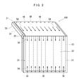
- 2 and 3 are a rear perspective view and a cross-sectional view schematically showing the configuration of the liquid crystal display device 100 of the present embodiment.
- the liquid crystal display device 100 of the present embodiment is a liquid crystal display device capable of displaying an image, specifically, a display device for digital signage used outdoors.
- the liquid crystal display device 100 according to this embodiment includes a liquid crystal panel 10, an irradiation unit 31 that irradiates light to the liquid crystal panel 10, and a control device (not shown) that controls driving of the liquid crystal panel 10.
- a plurality of plate-like members 20 (20A, 20B) are attached to a part (10a) of the liquid crystal panel 10.
- the plurality of plate-like members 20 (20A, 20B) are attached to the upper side portion 10a of the liquid crystal panel 10.
- the upper side portion 10a of the liquid crystal panel 10 is a portion located on the upper side when the liquid crystal panel 10 is arranged in the vertical direction.
- the plate-like member 20 has a first surface 21 located on the back side when the liquid crystal panel 10 is the front side, and a second surface 22 located on the surface opposite to the first surface 21.
- the second surface 22 is a surface on the front side when the liquid crystal panel 10 is the front side.
- a light guide 40 that collects external light and propagates light is disposed on the first surface 21 of the plate-like member 20.
- the light guide unit 40 is connected to the irradiation unit 31.
- the first surface 21 of the plate member 20 is provided with a plurality of optical sensors 46 that detect the amount of light.
- a plurality of LED elements 30 are arranged in the irradiation unit 31.
- the control device of the present embodiment is connected to an LED drive unit that controls the amount of light emitted from each of the plurality of LED elements 30, and the control device is connected to the optical sensor 46.
- a control apparatus is comprised so that the light quantity radiate
- the plate-like member 20 is rotatable around a rotation shaft 25 arranged around the upper side of the liquid crystal panel 10 (see arrow 27).
- the solar cell panel 80 can be disposed on the second surface 22 of the plate-like member 20.
- the plate-like member 20 can be rotated according to the orbit of the sun.
- a front light receiving sensor 35 that detects the amount of external light from the front surface is provided on the front surface of the liquid crystal display device 100. In the illustrated example, the front light receiving sensor 35 is disposed in the frame region 11 of the liquid crystal panel 10.
- the light guide 40 that collects the external light 51 and propagates the light 54 is disposed on the first surface 21 of the plate-like member 20.
- the light guide unit 40 is made of a transparent resin.
- a cover part 42 for protecting the light guide part 40 is provided.
- the cover part 42 consists of a translucent member, for example, is comprised from transparent resin or glass. More specifically, light (external light) 51 from the sun 50 is applied to the light guide unit 40 disposed on the first surface 21 of the plate-like member 20, and the light 52 is applied to the light guide unit 40. Is guided to the irradiation unit 31 as indicated by an arrow 54.
- the light 54 propagated through the light guide unit 40 is guided to the light guide plate 32 of the irradiation unit 31. It is also possible to form the light guide 40 and the light guide plate 32 as a continuous and integrated member.
- the optical sensor 46 of the present embodiment is provided on the upper end side of the plate-like member 20, and is specifically disposed between the upper end of the light guide unit 40 and the upper end of the plate-like member 20.
- the optical sensors 46 are arranged at equal intervals in a line from the left side to the right side. With this optical sensor 46, the light quantity of the light 52 applied to the light guide unit 40 can be measured.
- the light sensor 46 can measure the light amount of the light 52 irradiated to the light guides 40 in the respective portions ranging from the right side to the left side in the light guide unit 40.
- the optical sensor 46 is composed of a photoelectric conversion element, and can convert light irradiated on the optical sensor 46 into an electrical signal.
- the photoelectric conversion element constituting the optical sensor 46 is, for example, an element having a structure in which an amorphous silicon layer and a microcrystalline silicon layer are stacked. Note that the arrangement example of the optical sensor 46 is not limited to the example illustrated in FIG. 2, for example, and a suitable one can be adopted according to the usage form.
- the irradiation unit 31 of this embodiment is an edge light type backlight unit. As shown in FIG. 3, in the irradiation unit 31 of the present embodiment, a light guide plate 32 is disposed on the back surface of the liquid crystal panel 10, and a reflective film 34 is disposed on the back surface of the light guide plate 32. It is also possible to make the back surface of the light guide plate 32 a diffusion surface without forming the reflective film 34 on the back surface of the light guide plate 32. An end portion (for example, an upper end) of the light guide plate 32 is connected to the light guide portion 40 disposed on the plate-like member 20. Further, the end portion (for example, the lower end) of the light guide plate 32 is connected to the LED element 30.
- the light 54 that has propagated through the light guide unit 40 enters the light guide plate 32 and becomes light 55.
- the light 55 becomes irradiation light 58 that irradiates the liquid crystal panel 10 together with the light 56 emitted from the LED element 30 to the light guide plate 32.
- the liquid crystal panel 10 of this embodiment generally has a rectangular shape as a whole, and is composed of a pair of translucent substrates (glass substrates) 12A and 12B. Both the substrates 12A and 12B are disposed to face each other, and a liquid crystal layer 14 is provided therebetween.
- the liquid crystal layer 14 is made of a liquid crystal material whose optical characteristics change with application of an electric field between the substrates 12A and 12B.
- a sealing agent 15 is provided on the outer edge portions of the substrates 12A and 12B to seal the liquid crystal layer.
- polarizing plates 17A and 17B are attached to the outer surfaces of both the substrates 12A and 12B, respectively.
- the back side is the array substrate 12A
- the front side is the color filter substrate (CF substrate) 12B.
- the irradiation light 58 from the light guide plate 32 in the irradiation unit 31 passes through the polarizing plate 17A, the array substrate 12A, the liquid crystal layer 14, the CF substrate 12B, and the polarizing plate 17B, thereby displaying an image.
- a light diffusion film (not shown) can be disposed between the light guide plate 32 and the liquid crystal panel 10. When the light diffusing film is arranged, the light passing through the film is more diffused, so that a more uniform surface light source can be obtained.
- a virtual line (dotted line) is drawn on the light guide plate 32 to show the correspondence between each part of the light guide plate 32 and the LED element 30 in an easy-to-understand manner.
- the arrangement relationship / correspondence relationship of such LED elements 30 a suitable one according to the actual optical design of the irradiation unit 31 is appropriately adopted.
- the arrangement example of the LED elements 30 is not limited to the illustrated number and arrangement position, and can be appropriately changed to a suitable one.
- the LED element 30 is clearly shown for explanation.
- the LED element 30 is disposed on the end face of the light guide plate 32 in the frame region 11. Has been placed. Further, the light 54, the light 55, the light 56, and the like are indicated by arrows in a predetermined direction for easy understanding, but other light components exist.
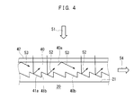
- FIG. 4 is an enlarged view showing a cross section of the light guide unit 40 of the present embodiment.
- the bottom surface 40b of the light guide unit 40 of the present embodiment has a saw-like cross section so that light propagating through the light guide unit 40 travels in the direction of the arrow 54 as a whole.
- the light 52 reflected from the bottom surface 40b of the light guide 40 is guided from a plurality of inclined surfaces 41a such that the light 52 travels in the direction of the arrow 54, and a vertical surface (or substantially vertical surface) 41b for forming the inclined surface 41a.
- the bottom surface 40b of the optical unit 40 is configured. Further, a part (53) of the light traveling in the light guide 40 reflects the upper surface 40a of the light guide 40 and proceeds in the direction of the arrow 54. Then, the light (54) propagating through the light guide unit 40 reaches the light guide plate 32 of the irradiation unit 31.
- FIG. 5 is a block diagram for explaining the configuration of the liquid crystal display device 100 of the present embodiment.
- the liquid crystal display device 100 of the present embodiment includes a liquid crystal panel 10, an irradiation unit 31 of the liquid crystal panel 10, a light guide unit 40, and a control device 61 that controls driving of the liquid crystal panel.
- the control device 61 is composed of a semiconductor integrated circuit, and is, for example, an MPU (micro processor unit). Further, the control device 61 can be provided with a storage device (semiconductor memory, hard disk, optical disk, etc.), and various programs can be stored in the storage device, and various data and calculation results can be stored. It is.
- the control device 61 executes the display of the liquid crystal panel 10 by controlling the liquid crystal panel driving unit 62.
- the liquid crystal panel driving unit 62 is a part that displays an image on the liquid crystal panel 10 by driving the liquid crystal panel 10.
- the liquid crystal panel driving unit 62 drives the liquid crystal panel 10 based on a signal input from the control device 61.
- the liquid crystal panel drive unit 62 corresponds to a driver circuit such as a gate driver or a source driver.
- the liquid crystal panel driving unit 62 not only displays an image on the entire surface of the liquid crystal panel 10, but also only on a part of the display screen of the liquid crystal panel 10 (for example, the central portion) based on a signal from the control device 61. It is also possible to drive the liquid crystal panel 10 so as to display an image.
- the control device 61 is connected to an LED drive unit (for example, LED driver circuit) 63 that controls the amount of light emitted from each of the plurality of LED elements 30.
- a plurality of the LED elements 30 are arranged so as to emit light to the light guide plate included in the irradiation unit 31, and are made of, for example, a white LED.
- the white LED constituting the LED element 30 is a combination of a blue LED and a phosphor, but other ones (such as a combination of an ultraviolet LED and a phosphor) can also be used.
- the LED element 30 is shown as a representative example of a dimmable point light source used for changing and displaying the emission intensity for each area of the liquid crystal panel 10.
- the LED driving unit 63 is a part for individually turning on / off the plurality of LED elements 30 and changing the light emission intensity.
- the LED driving unit 63 can individually drive the LED elements 30 based on signals input from the control device 61.
- the LED drive unit 63 is configured by a driver circuit including, for example, a switch.
- control device 61 is connected to the movable portion 64 that rotates the plate-like member 20.
- the movable portion 64 is connected to the rotation shaft 25 of the plate-like member 20 and can turn the plate-like member 20 based on a signal input from the control device 61.
- the movable part 64 is, for example, a motor that can rotate the plate-like member 20.
- an external system 65 and an external power source 66 are separately connected to the control device 61.
- the external system 65 is a device for inputting image information to the control device 61.
- the external system 65 corresponds to, for example, a stand-alone personal computer (PC) or a PC connected to a network server that stores image information.
- the external power supply 66 is a power supply for supplying power to the liquid crystal display device 100 of the present embodiment, and corresponds to, for example, a commercial power supply.
- the optical sensor 46 provided on the plate-like member 20 is connected to the control device 61.
- the control apparatus 61 acquires the data of the light quantity which the optical sensor 46 corresponding to each light guide part 40 detected.
- the control device 61 is connected to the front light receiving sensor 35. Therefore, the control device 61 can also acquire data on the amount of light detected by the front light receiving sensor 35 (that is, the amount of external light from the front).
- control device 61 the liquid crystal panel driving unit 62, the LED driving unit 63, and the movable unit 64 are shown as separate functional members, but some or all of them are integrated into one semiconductor integrated circuit. It is also possible to construct with a circuit.
- the light parameter detected by the light sensor 46 or the light parameter processed by the control device 61 (or the LED drive unit 63) may be any parameter that can be handled by the irradiation unit (backlight unit) 31. Therefore, in this sense, it is possible not only to process with the numerical data of the light amount, but also to use other optical parameters such as luminous flux / luminosity and luminance.
- FIG. 6 is a flowchart for explaining a control method of the liquid crystal display device 100 of the present embodiment.
- step S110 information on the amount of light from the optical sensor 46 is acquired (step S110).
- step S110 information on the amount of light of each of the plurality of optical sensors 46 is input to the control device 61.
- step S120 the output of the LED element (LED light source) 30 is adjusted so that the display brightness of the liquid crystal panel 10 becomes uniform.
- the control device 61 performs light control of the LED element 30 by controlling the LED drive unit 63 based on the information of the light sensor 46, so that the display brightness of the liquid crystal panel 10 becomes uniform. To do.
- FIGS. 7 and 8 are perspective views schematically showing the configuration of the liquid crystal display device 100 corresponding to FIGS. 1 and 2, respectively.
- FIG. 9 is a flowchart for explaining the control method of the present embodiment.
- the amount of light collected by the light guide 40 in the region (51B) where the shadow is present is different from the amount of light collected by the light guide 40 in the region (51A) where no shadow is present.
- the light collected and propagated by the light guide unit 40 is used as a backlight. Therefore, the variation in the amount of light by each part of the light guide unit 40 is the luminance of the liquid crystal panel 10. Will lead to variations. Possible causes of shadows are the presence of trees, utility poles, buildings, and the like. Moreover, even if there is no shadow at a certain time, there is a possibility that the sun will move and the time when the shadow will occur.
- step S110 information on the amount of light is acquired from each optical sensor 46 (step S110), and then the variation in the amount of light is calculated (step S122).
- the control device 61 calculates the variation in the amount of light between the optical sensors 46.
- the control apparatus 61 adjusts the emitted light intensity of the light radiate
- the light emission intensity of the LED element 30 that emits to the region corresponding to the shadowed region (51B) is increased, and the LED that emits to the region corresponding to the bright region (51A) as compared with it.
- the light emission intensity of the element 30 is reduced.
- the control device 61 calculates the light amount (or light emission intensity) of the light 55 emitted from the light guide unit 40 corresponding to the portion based on the light amount information of each optical sensor 46. And each LED element 30 is radiate
- the light emission intensity of each LED element 30 is determined so as to reduce the variation of the light 55 from the light guide unit 20.
- the processing for reducing such variation is not limited to the case where, for example, a control circuit is formed in the control device 61 itself, and processing is performed by the control circuit.
- a program stored in a storage device connected to the control device 61 for example, a data processing program for the optical sensor 46, a program for determining the light emission intensity of the LED element 30
- the control device is based on the program. 61 may be executed.
- the configuration of the optical members in the light guide 40 and the irradiation unit 31 not only the variation by the determination of the light emission intensity of each LED element 30 but also the light emission intensity of the light 55 emitted from the end face of the light guide 40 can be reduced.
- Dispersion alleviation may be executed by using the processing to be performed together. Furthermore, the variation reduction processing here is performed in the case where the light emission luminance is made uniform over the entire surface of the liquid crystal panel 10, and for example, the light emission luminance in the central portion of the liquid crystal panel 10 is slightly increased to Some of the emission luminance is slightly lower than that.
- the liquid crystal display device 100 of the present embodiment is provided with a front light receiving sensor 35, and the front light receiving sensor 35 is connected to the control device 61. Therefore, it is possible to determine the intensity of the light 58 that the irradiating unit 31 irradiates the liquid crystal panel 10 based on the information on the brightness of the external light detected by the front light receiving sensor 35.
- an antireflection film is preferably disposed on the surface of the liquid crystal panel 10 in order to suppress reflection.
- the CF substrate 12B in the liquid crystal panel 10 corresponds to the sunlight spectrum. It is preferable to form a colored filter.
- the irradiation unit 31 is preferably provided with an LED element 30 that emits outgoing light having a light spectrum in consideration of the sunlight spectrum. In this way, by forming the color filter and the LED element 30 in a form corresponding to the sunlight spectrum, the difference between the spectrum of the edge light and the spectrum of the sunlight is alleviated, so that a sense of incongruity does not occur. be able to.
- the control device 61 since the control device 61 is connected to the movable portion 64 that rotates the plate-shaped member 20, the control device 61 can rotate the plate-shaped member 20 in accordance with the orbit of the sun 50. . Accordingly, the plate-like member 20 can be positioned at a position where the external light 51 can be efficiently collected by the light guide unit 40. For example, as in the example shown in FIG. 3, when the sun 50 is located on the right side, the sun 50 is inclined to the left with respect to the vertical direction (vertical direction) (for example, 15 ° to 45 ° on the left side). ). On the other hand, in the example shown in FIG.
- the plate-like member 20 when the sun 50 is located on the left side, the plate-like member 20 is extended in the horizontal direction (that is, 90 ° with respect to the vertical direction), and the outside light 51 is transmitted.
- the light can be collected by the light guide unit 40.
- Such rotation of the plate-like member 20 in accordance with the orbit of the sun 50 starts a program (orbit tracking program of the sun 50) stored in a storage device connected to the control device 61, Control may be performed by the control device 61 based on this.
- a transflective liquid crystal panel capable of switching between the transmission mode and the reflection mode can be used as the liquid crystal panel 10. That is, in this case, the liquid crystal panel 10 is a transflective liquid crystal panel capable of switching between a transmission mode using the light 58 from the irradiation unit 31 and a reflection mode using external light from the front.
- a transflective liquid crystal panel is disclosed in, for example, Japanese Patent Application Laid-Open No. 2007-219172.
- a switch liquid crystal panel that switches the polarization state of transmitted light in accordance with the drive voltage is arranged between the liquid crystal panel (main liquid crystal panel) 10 and the irradiation unit (backlight) 31, and the switch liquid crystal panel and the irradiation are arranged.
- a reflective polarizing plate is disposed between the unit 31. Then, the transflective liquid crystal panel is realized by switching the display state between the reflection mode and the transmission mode by switching on / off the irradiation unit 31 and switching the driving voltage of the switch liquid crystal panel. Can do.
- the liquid crystal panel 10 can be used as a reflection mode when external light from the front is strong.
- the control device 61 switches between the transmission mode and the reflection mode in the transflective liquid crystal panel 10 based on the amount of light detected by the front light receiving sensor 35 (for example, if it is a predetermined value or more).
- the reflection mode when the sun 50 is located on the front side, it is suitable for the reflection mode. In that case, even if the plate-like member 20 is rotated to be parallel (or substantially parallel), the amount of light collected by the light guide unit 40 is small, so that the transmission mode is not suitable.
- the external light hitting the front of the liquid crystal panel 10 is strong, it will feel dark unless the display brightness of the liquid crystal panel 10 is increased. Therefore, even if the amount of light collected by the light guide unit 40 is small, the light from the irradiation unit 31 It is desirable to increase the amount of 58. Therefore, the power consumption of the LED element 30 tends to increase. Therefore, in the case of the transflective liquid crystal panel 10, when the external light from the front is strong, it is preferable to use the liquid crystal panel 10 as a reflection mode.
- the transflective liquid crystal panel 10 can be used as a transmission mode.
- the control device 61 switches between the transmission mode and the reflection mode in the transflective liquid crystal panel 10 based on the amount of light detected by the front light receiving sensor 35 (for example, if it is less than a predetermined value).
- the transmission mode when the sun 50 is located on the back side, if the plate-like member 20 is appropriately rotated and inclined, the amount of light collected by the light guide 40 can be increased. Suitable for Therefore, in the case of the transflective liquid crystal panel 10, when the external light from the front is weak, it is preferable to use the liquid crystal panel 10 as a transmission mode.
- the use of a transflective liquid crystal panel capable of switching between the transmissive mode and the reflective mode has been described as the liquid crystal panel 10, but the liquid crystal panel 10 is capable of switching between the transmissive mode and the reflective mode. Even if this is not possible, it is possible to use a transflective liquid crystal panel that can use the transmissive mode and the reflective mode. Specifically, by providing a reflective portion (reflective electrode) at a portion not related to transmissive display in the pixel area of the liquid crystal panel 10 together with a transmissive display portion (transmissive electrode), the transmissive mode and the reflective mode are set. An available transflective liquid crystal panel can be realized. A transflective liquid crystal panel can realize transmittance and image quality close to those of a transmissive type, and can achieve high visibility under external light.
- the light guide unit 40 is disposed on the first surface 21 of the plate-like member 20 attached to the upper side of the liquid crystal panel 10. Are connected to the irradiation unit 31.
- a plurality of optical sensors 46 are provided on the first surface 21 of the plate-like member 20.
- the control device 61 is configured to control the amount of light emitted from each LED element 30 by the LED drive unit 63 based on the amount of light detected by each light sensor 46. Therefore, when the liquid crystal display device 100 of the present embodiment is used as an outdoor digital signage, the outside light 51 can be taken in and used as the light (55, 58) of the irradiation unit 31.
- control device 61 controls the amount of light emitted from each LED element 30 by the LED drive unit 63 on the basis of the amount of light detected by the optical sensor 46, external light taken in by the surrounding environment or the like Even if the amount of light changes (see the areas 51A and 51B shown in FIG. 8), the light 58 applied to the liquid crystal panel 10 can be made uniform, and as a result, an image can be displayed appropriately. it can.
- the light collected by the light guide unit 40 is used as the irradiation light of the irradiation unit 31 of the liquid crystal panel 10, so that the light (outside light) that is significantly stronger than the light of the room illumination is used. can do. Therefore, it is possible to solve or alleviate the fact that outdoor digital signage feels dark against outside light, and it is possible to reduce the power consumption of the backlight (irradiation unit 31).
- the light guide unit 40 it is desirable that the light from the backlight is strengthened to such an extent that it does not feel dark with respect to outside light, so that the power consumption of the backlight increases.
- the power consumption of the backlight can be suppressed.
- the light 56 emitted from the LED element 30 in the irradiating unit 31 is adjusted and emitted so as to reduce variation in the amount of light 55 emitted from the end surface of the light guide unit 40. Therefore, the power consumption can be reduced as compared with the case where the light guide 40 is not present.
- the liquid crystal panel 10 has a large screen (for example, a panel having a dimension of 60 inches or more)
- the power consumption is increased, and thus the running cost is increased. Compared with the case where the part 40 does not exist, power consumption can be reduced significantly.
- the plate-like member 20 can be controlled as follows. As shown in FIG. 10, when the sun 50 is located on the front side of the liquid crystal panel 10 and the external light 51 from the front is strong, the liquid crystal panel 10 can be used as a reflection mode as described above. it can. When used as the reflection mode, the light guide 40 provided on the first surface 21 of the plate-like member 20 may not be used.
- the solar cell panel 80 is provided on the second surface 22 of the plate-like member 20 so that the solar cell panel 80 receives the external light 51 (that is, in the illustrated example, the It is preferable that the position of the plate-like member 20 is controlled by the control device 61 so that the two surfaces 22 are inclined.
- the electricity generated by the solar cell panel 80 can be used as power for driving the liquid crystal display device 100.
- the plate-like member 20 when the liquid crystal panel 10 is arranged in the vertical direction 90, the plate-like member 20 (in other words, the first surface 21 or the second surface 22 of the plate-like member 20) is as shown in FIG. As shown in FIG. 10, it can be configured to be inclined with respect to the vertical direction 90. Specifically, when the plate-like member 20 can be moved, the plate-like member 20 can be fixed at a position between the vertical direction 90 and the horizontal direction, or when the plate-like member 20 is fixed. The plate member 20 is fixed at a position between the vertical direction 90 and the horizontal direction.
- the plate-like member due to the external light 51 is disposed when the plate-like member 20 is disposed obliquely as shown in FIG. It is possible to prevent 20 shadows from being generated on the upper portion of the liquid crystal panel 10.
- the LED elements 30 are arranged at the lower end of the irradiation unit 31.
- the method of arranging the LED elements 30 is not limited thereto.
- the LED element 30 may be arranged with the LED element 30 ⁇ / b> A at the lower end of the irradiation unit 31 and with the LED element 30 ⁇ / b> B at the left end and the right end of the irradiation unit 31. It is also possible to arrange the LED elements 30 ⁇ / b> A at the lower end of the irradiation unit 31 and to arrange the LED elements 30 ⁇ / b> B only at one of the left end and the right end of the irradiation unit 31.
- the specific specifications and arrangement of the LED elements 30 are determined based on the optical design of the liquid crystal display device 100 to be used, and suitable ones can be adopted as appropriate.
- the configuration in which only one front light receiving sensor 35 is provided on the front surface of the liquid crystal display device 100 is shown, but not limited thereto, as illustrated in FIG. It can also be provided.
- the liquid crystal panel includes the intensity of external light received by the other front light receiving sensors 35. The intensity of external light on the front side of the ten can be determined.
- the front light receiving sensor 35 is not only arranged in the frame area 11 of the liquid crystal panel 10 but can also be built in the substrate of the liquid crystal panel 10 (for example, the array substrate 12A).
- the optical sensor 46 is disposed on the surface of the light guide unit 40, but the present invention is not limited thereto.
- the optical sensor 46 can be disposed so as to detect the light amount of the light guide unit 40 in the plate-like member 20.
- the optical sensor 46 arranged so as to detect the light propagating to the light guide unit 40 is emitted to the light guide plate 32 of the irradiation unit 31. It becomes easy to predict the light quantity of the light 55.
- the LED element 30 is disposed at the end of the irradiation unit 31.
- the present invention is not limited thereto, and for example, the LED element 30 is disposed on the back surface of the light guide plate 32 as illustrated in FIG. Is also possible.
- a reflection pattern (or diffusion pattern) 33 is formed on the light guide plate 32, and the reflection pattern 33 and the LED elements 30 are arranged in a matrix as viewed from the back side.
- the LED elements 30 are arranged between the reflection patterns 33.
- the control device 61 adjusts the light amount emitted from each LED element 30 so that the variation in the light amount detected by each light sensor 46 is reduced. Can do.
- the plate-like member 20 is attached to the upper side portion 10a of the liquid crystal panel 10.
- the present invention is not limited to this, and a configuration example as shown in FIG.
- the plate-like member 20 has an extension 20 a, and the extension 20 a is attached to the upper side 10 a of the liquid crystal panel 10.
- a rotation shaft 25 is provided on the upper side of the extension portion 20 a, and a plate-like member (main body portion) 20 having a first surface 21 and a second surface 22 is provided on the rotation shaft 25. It is connected.
- the upper side portion of the liquid crystal panel 10 is not limited to the case where the plate-like member 20 is attached to the upper side portion 10 a of the liquid crystal panel 10, as long as the strength of the plate-like member 20 can be maintained.
- the plate member 20 may be attached to a portion other than 10a.
- a support member that supports the plate-like member 20 can be provided on the upper part of the left and right side surfaces when the liquid crystal panel 10 is arranged in the vertical direction, and the plate-like member 20 can be supported by the support member.
- the plate-like member 20 and the upper side portion 10a may not be in an attached relationship.
- the image display unit is configured by using one liquid crystal panel 10, but it is also possible to configure one image display unit by combining a plurality of liquid crystal panels 10.
- a daylighting type liquid crystal display device for example, digital signage
- a daylighting type liquid crystal display device capable of appropriately displaying an image
Landscapes
- Physics & Mathematics (AREA)
- General Physics & Mathematics (AREA)
- Engineering & Computer Science (AREA)
- Optics & Photonics (AREA)
- Nonlinear Science (AREA)
- Chemical & Material Sciences (AREA)
- Computer Hardware Design (AREA)
- Theoretical Computer Science (AREA)
- Crystallography & Structural Chemistry (AREA)
- Mathematical Physics (AREA)
- Liquid Crystal (AREA)
- Devices For Indicating Variable Information By Combining Individual Elements (AREA)
- Planar Illumination Modules (AREA)
Abstract
画像を適切に表示することが可能な採光型の液晶表示装置を提供する。液晶パネル10と、照射部31と、制御装置61と、液晶パネル10の一部(10a)に取り付けられた板状部材20とを備えた液晶表示装置100である。板状部材20の第1面21には外光51を採光して光を伝播する導光部40が配置され、導光部40は照射部31に接続されている。板状部材20の第1面21には、光センサ46が複数設けられ、照射部31には複数のLED素子30が配置され、制御装置61はLED駆動部63に接続され、制御装置61は光センサ46に接続されている。制御装置61は、光センサ46が検出した光量を基準にして、LED駆動部63によって各LED素子30から出射される光量を制御するように構成されている。
Description
本発明は、液晶表示装置に関する。特に、外光を採り込んでこれをバックライトとして利用する液晶表示装置に関する。
なお、本出願は2010年7月9日に出願された日本国特許出願2010-156907号に基づく優先権を主張しており、その出願の全内容は本明細書中に参照として組み入れられている。
なお、本出願は2010年7月9日に出願された日本国特許出願2010-156907号に基づく優先権を主張しており、その出願の全内容は本明細書中に参照として組み入れられている。
近年、デジタルサイネージが注目を集めている。デジタルサイネージ(Digital Signage)とは、デジタル技術を応用した情報伝達媒体のことである。デジタルサイネージは、主として家庭外で人が多く集まる場所(例えば、駅や空港、ショッピングセンタ、公共施設等)に設置されて、広告やニュース等の情報を静止画や動画、テロップ等の画像を用いて表示する。ここで、デジタルサイネージを具体的に実現する装置としては、液晶表示装置が好適に利用されている。
液晶表示装置は、一対の透光性基板の間に液晶が封止されてなる液晶パネルと、当該液晶パネルの背面側に配置されたバックライトユニットとから構成されている。液晶表示装置では、バックライトユニットから出射された光が液晶パネルの背面側から照射されることによって、液晶パネルに表示された画像が視認可能となる。この液晶表示装置をデジタルサイネージとして利用することにより、静止画や動画、テロップ等の画像を色鮮やかな色彩を用いて自由に表現することが可能となるため、情報伝達媒体としての表現性が飛躍的に向上することになる。
しかしながら、デジタルサイネージとして液晶表示装置を利用した場合には、設置の際のイニシャルコストが高くつくばかりでなく、そのランニングコストが高くつくという問題がある。ランニングコストが高くつく主たる要因は、上述したバックライトユニットに内蔵される光源の消費電力が大きい点にある。近年においては、液晶表示装置の表示画面の大型化が飛躍的に進んでおり、このような大型の表示画面を備えた液晶表示装置においては、バックライトユニットに内蔵される光源の消費量もこれに応じて増大する傾向にある。近年においては、比較的低い消費電力の発光ダイオード(LED)がバックライトユニットの光源として利用され始めているが、それでも、長期間の使用を考慮すればさらなる低消費電力化は欠かせない。
そこで、太陽電池パネルを利用して発電を行い、発電した電力を利用して光源を駆動することで、低消費電力化を図った液晶表示装置が提案されている。しかしながら、当該液晶表示装置をデジタルサイネージとして利用した場合には、太陽電池パネルが比較的高価であるため、その設置コストが増大するといった問題がある。また、太陽電池パネルの耐用期間が必ずしも長くないために、太陽電池パネルを定期的に交換する必要が生じて結果的にランニングコストが高くつくといった問題が別途生じてしまうことになる。
一方で、液晶表示装置をデジタルサイネージとして利用するものでないものの、標識等の静止画を表示する表示装置において、太陽光等の外光を採光部から採り込み、その採り込んだ光を光ファイバ等で表示パネルに搬送して、バックライトとして利用する表示装置が提案されている(例えば、特許文献1参照)。ここで、当該表示装置における表示パネルを液晶パネルに変更した場合には、採光した光をそのまま液晶パネルのバックライトとして利用することができることになり、低消費電力化を図ることができるのみならず、その耐用期間も長くすることができる。その結果、ランニングコストを大幅に削減することが可能になる。また、当該構成を採用すれば、上述した太陽電池パネルを利用した液晶表示装置を用いた場合に比べ、設置コストも大幅に削減することができる。
しかしながら、上述した採光型の液晶表示装置をデジタルサイネージとして利用した場合には、夜間において外光の採光がほとんど行えないため、昼間のみにしかその利用ができないといった問題がある。さらには、昼間においても天候や周囲環境などによって採り込まれる外光の光量に不足が生じた場合に、十分な輝度をもって適切に画像を表示することができないといった問題が生じてしまうことになる。特に、後者の問題は、近年の液晶表示装置の表示画面の大型化に伴い、当該大型の表示画面を備えた液晶表示装置をデジタルサイネージとして利用した場合に顕著になる。
本発明はかかる点に鑑みてなされたものであり、その主な目的は、画像を適切に表示することが可能な採光型の液晶表示装置を提供することにある。
本発明に係る液晶表示装置は、画像を表示可能な液晶表示装置であり、液晶パネルと、前記液晶パネルに光を照射する照射部と、前記液晶パネルの駆動を制御する制御装置と、前記液晶パネルの一部に取り付けられた板状部材とを備え、前記板状部材の第1面には、外光を採光して光を伝播する導光部が配置されており、前記導光部は、前記照射部に接続されており、前記板状部材の前記第1面には、光量を検出する光センサが複数設けられており、前記照射部には、複数のLED素子が配置されており、前記制御装置は、前記複数のLED素子のそれぞれから出射される光量を制御するLED駆動部に接続されており、前記制御装置は、前記光センサに接続されており、前記制御装置は、前記光センサが検出した光量を基準にして、前記LED駆動部によって前記複数のLED素子のそれぞれから出射される光量を制御するように構成されている。
ある好適な実施形態において、前記板状部材は、前記液晶パネルの上辺部の周辺に配置された回転軸を中心に回動可能であり、前記板状部材の前記第1面とは反対側に位置する第2面には、太陽電池パネルが配置されている。
ある好適な実施形態において、前記制御装置は、前記板状部材の回動を制御する可動制御部に接続されており、前記可動制御部は、太陽の軌道に応じて前記板状部材の回動を制御するように構成されている。
ある好適な実施形態において、前記照射部は、導光板を含んでおり、前記導光部は、前記照射部の前記導光板に接続されている。
ある好適な実施形態において、前記光センサは、光電変換素子から構成されている。
ある好適な実施形態において、前記液晶表示装置の正面には、当該正面からの外光の光量を検出する正面受光センサが設けられており、前記液晶パネルは、前記照射部からの光を利用する透過モードと、前記正面からの外光を利用する反射モードとの切替が可能な半透過型液晶パネルであり、前記制御装置は、前記正面受光センサが検出した光量を基準にして、前記半透過型液晶パネルにおける前記透過モードと前記反射モードとの切替を実行するように構成されている。
ある好適な実施形態において、前記正面受光センサは、前記液晶パネルの額縁領域に配置されている。
ある好適な実施形態において、前記照射部は、エッジライト型バックライトユニットであり、前記制御装置は、前記光センサが検出した光量のバラツキが軽減されるように、前記照射部に配置された前記複数のLED素子のそれぞれから出射される光量を調整する。
ある好適な実施形態において、前記板状部材は、前記液晶パネルの上辺部の周辺に配置された回転軸を中心に回動可能であり、前記板状部材の前記第1面とは反対側に位置する第2面には、太陽電池パネルが配置されており、前記制御装置は、前記板状部材の回動を制御する可動制御部に接続されており、前記可動制御部は、太陽の軌道に応じて前記板状部材の回動を制御するように構成されており、前記液晶表示装置の正面には、当該正面からの外光の光量を検出する正面受光センサが設けられており、前記液晶パネルは、前記照射部からの光を利用する透過モードと、前記正面からの外光を利用する反射モードとの切替が可能な半透過型液晶パネルであり、前記制御装置は、前記正面受光センサが検出した光量を基準にして、前記半透過型液晶パネルにおける前記透過モードと前記反射モードとの切替を実行するように構成されており、前記制御装置は、前記透過モードに切替したときには、前記板状部材の前記第1面が前記太陽からの外光を受けるように、前記可動制御部によって前記板状部材の回動を制御し、そして、前記反射モードに切替したときには、前記板状部材の前記第2面が前記太陽からの外光を受けるように、前記可動制御部によって前記板状部材の回動を制御する。
ある好適な実施形態において、前記液晶パネルを鉛直方向に配置したときにおいて、前記板状部材の第1面は、当該鉛直方向と水平方向との間に位置している。
ある好適な実施形態において、前記液晶表示装置は、屋外に設置されるデジタルサイネージ用表示装置である。
本発明に係る液晶表示装置の制御方法は、外光を採光して、採光した光を液晶パネルの背面に照射して画像を表示する液晶表示装置の制御方法であり、前記液晶表示装置は、液晶パネルと、前記液晶パネルに光を照射する照射部と、前記液晶パネルの駆動を制御する制御装置と、前記液晶パネルの一部に取り付けられた板状部材とを備え、前記板状部材の第1面には、外光を採光して光を伝播する導光部が配置されており、前記導光部は、前記照射部に接続されており、前記板状部材の前記第1面には、光量を検出する光センサが複数設けられており、前記照射部には、複数のLED素子が配置されており、前記制御装置は、前記複数のLED素子のそれぞれから出射される光量を制御するLED駆動部に接続されており、前記制御装置は、前記光センサに接続されており、前記制御装置は、前記光センサが検出した光量のデータを取得するステップ(a)と、前記光量のデータにおけるバラツキを算出するステップ(b)と、前記バラツキを軽減するように、前記複数のLED素子のそれぞれから出射される光量を調整するステップ(c)を実行する。
ある好適な実施形態において、前記板状部材は、前記液晶パネルの上辺部の周辺に配置された回転軸を中心に回動可能であり、前記板状部材の前記第1面とは反対側に位置する第2面には、太陽電池パネルが配置されており、前記液晶表示装置の正面には、当該正面からの外光の光量を検出する正面受光センサが設けられており、前記液晶パネルは、前記照射部からの光を利用する透過モードと、前記正面からの外光を利用する反射モードとの切替が可能な半透過型液晶パネルであり、前記制御装置は、前記正面受光センサが検出した光量を基準にして、前記半透過型液晶パネルにおける前記透過モードと前記反射モードとを切り替えるステップを実行し、そして、前記制御装置は、前記透過モードに切り替えたときには、前記板状部材の前記第1面が前記太陽からの外光を受けるように前記板状部材の回動を制御し、そして、前記反射モードに切り替えたときには、前記板状部材の前記第2面が前記太陽からの外光を受けるように前記板状部材の回動を制御する。
本発明の液晶表示装置によれば、液晶パネルの一部に取り付けられた板状部材の第1面には、導光部が配置され、そして、導光部は、液晶パネルに光を照射する照射部に接続されている。板状部材の第1面には、光量を検出する光センサが設けられている。制御装置は、光センサが検出した光量を基準にして、LED駆動部によって複数のLED素子のそれぞれから出射される光量を制御するように構成されている。
したがって、液晶表示装置を屋外でのデジタルサイネージとして用いる場合において、外光を採り込んでその光を照射部の光に利用することができるので、屋外に設置されたデジタルサイネージが外光に対して暗く感じることを抑制することができ、加えて、複数のLED素子によって、周囲環境などによって採り込まれる外光の光量が変化したとしても、画像を適切に表示することができる。
したがって、液晶表示装置を屋外でのデジタルサイネージとして用いる場合において、外光を採り込んでその光を照射部の光に利用することができるので、屋外に設置されたデジタルサイネージが外光に対して暗く感じることを抑制することができ、加えて、複数のLED素子によって、周囲環境などによって採り込まれる外光の光量が変化したとしても、画像を適切に表示することができる。
本願発明者は、液晶表示装置を屋外でのデジタルサイネージ(電子広告)として用いる場合について検討したところ、以下のような知見を得た。まず、反射型の液晶パネルを備えた液晶表示装置を用いた場合、夜間および外光が弱い場合には、デジタルサイネージを表示させることができないという問題がある。また、反射型の液晶パネルの場合、透過型の液晶パネルのものと比較して色再現性やコントラスト比が劣り、デジタルサイネージの良好な画像表示という点で問題が残る。
さらに、透過型の液晶パネルを用いた場合でも、屋外に設置されたデジタルサイネージは外光に対して暗く感じる場合がある。これは、屋外の光(晴天昼太陽光:約10万ルクス)は、室内照明の光(蛍光灯照明事務所:約400ルクス)に対して約250倍も強い照度を有することに起因している。一方で、液晶パネルに対して屋外光に対応できるだけの光を発するバックライトを取り付けることは現実的にはできない。したがって、屋外のデジタルサイネージが外光に対して暗く感じる問題を解消することは難しい。
また、本願発明者は、太陽光等の外光を採り込んでその光をバックライトとして利用した場合、屋外に設置されたデジタルサイネージが外光に対して暗く感じる問題を解決できるとともに、低消費電力化を図ることができるという知見を得た。しかしながら、採り込んだ外光をバックライトとして利用した場合、夜間には表示を行うことができないとともに、昼間においても天候や周囲環境などによって採り込まれる外光の光量が変化することの影響を受けてしまう。そのような影響を残したままでは、反射型の液晶パネルを備えたデジタルサイネージと同様に、デジタルサイネージの良好な画像表示という点で問題が残る。
本願発明者は上述の問題を鋭意検討し、そのような問題を解決できるような液晶表示装置(デジタルサイネージ)を想到し、本発明に至った。
以下、図面を参照しながら、本発明の実施形態を説明する。以下の図面においては、説明の簡潔化のために、実質的に同一の機能を有する構成要素を同一の参照符号で示す。なお、本発明は以下の実施形態に限定されない。
図1は、本発明の実施形態に係る液晶表示装置100の構成を模式的に示す正面斜視図である。また、図2および図3は、本実施形態の液晶表示装置100の構成を模式的に示す裏面斜視図および断面図である。
図1に示すように、本実施形態の液晶表示装置100は、画像を表示可能な液晶表示装置であり、具体的には、屋外で使用されるデジタルサイネージ用の表示装置である。本実施形態の液晶表示装置100は、液晶パネル10と、液晶パネル10に光を照射する照射部31と、液晶パネル10の駆動を制御する制御装置(不図示)とから構成されている。
また、液晶パネル10の一部(10a)には、複数の板状部材20(20A、20B)が取り付けられている。本実施形態では、複数の板状部材20(20A、20B)は、液晶パネル10の上辺部10aに取り付けられている。なお、液晶パネル10の上辺部10aは、液晶パネル10を鉛直方向に配置した場合に上方側に位置する部位である。板状部材20は、液晶パネル10を正面側としたときの裏面側に位置する第1面21と、第1面21の反対側の面に位置する第2面22とを有している。換言すると、第2面22は、液晶パネル10を正面側としたときの正面側の面である。
図2に示すように、板状部材20の第1面21には、外光を採光して光を伝播する導光部40が配置されている。そして、導光部40は、照射部31に接続されている。また、板状部材20の第1面21には、光量を検出する光センサ46が複数設けられている。さらに、照射部31には、複数のLED素子30が配置されている。ここで、本実施形態の制御装置は、複数のLED素子30のそれぞれから出射される光量を制御するLED駆動部に接続されており、制御装置は、光センサ46に接続されている。そして、本実施形態の構成によれば、制御装置は、各光センサ46が検出した光量を基準にして、LED駆動部によって複数のLED素子30のそれぞれから出射される光量を制御するように構成されている。
また、本実施形態の構成では、図1に示すように、板状部材20は、液晶パネル10の上辺周辺に配置された回転軸25を中心に回動可能となっている(矢印27参照)。また、板状部材20の第2面22に、太陽電池パネル80を配置することも可能である。さらに、板状部材20は、太陽の軌道に応じて回動させることも可能である。太陽の軌道に応じて回動させる場合には、そのようなプログラムを制御装置によって実現できるように、すなわち、そのような回動を実行可能なように制御装置を構築しておくことが好ましい。加えて、液晶表示装置100の正面には、当該正面からの外光の光量を検出する正面受光センサ35が設けられている。図示した例では、正面受光センサ35は、液晶パネル10の額縁領域11に配置されている。
図3に示すように、板状部材20の第1面21には、外光51を採光して光54を伝播する導光部40が配置されている。導光部40は、透明樹脂から構成されておる。図示した例では、導光部40を保護するためのカバー部42が設けられている。カバー部42は、透光性部材からなり、例えば、透明樹脂またはガラスから構成されている。さらに説明すると、太陽50からの光(外光)51は、板状部材20の第1面21上に配置された導光部40に照射され、そして、導光部40に照射された光52は、矢印54に示すように照射部31に導かれる。ここでは、導光部40を伝播した光54は、照射部31の導光板32へと導かれる。なお、導光部40と導光板32とを連続した一体化した部材として形成することも可能である。
本実施形態の光センサ46は、板状部材20の上端側に設けられており、具体的には、導光部40の上端と板状部材20の上端との間に配置されている。この例では、光センサ46は、左側から右側にわたって一列に等間隔に配列されている。この光センサ46によって、導光部40に照射される光52の光量を計測することができる。具体的には、光センサ46によって、導光部40における右側から左側にわたる各部位の導光部40に照射される光52の光量を測定することができる。光センサ46は、光電変換素子から構成されており、光センサ46の上に照射された光を電気信号に変換することができる。光センサ46を構成する光電変換素子は、例えば、アモルファスシリコン層と微結晶シリコン層が積層された構造を有する素子である。なお、光センサ46の配置例は、例えば図2に示した例に限らず、使用形態にあわせて適宜好適なものを採用することが可能である。
本実施形態の照射部31は、エッジライト型バックライトユニットである。図3に示すように、本実施形態の照射部31では、液晶パネル10の背面に導光板32が配置され、その導光板32の背面に反射フィルム34が配置されている。なお、導光板32の背面に反射フィルム34を形成せずに、導光板32の背面を拡散面にすることも可能である。導光板32の端部(例えば、上端)は、板状部材20に配置された導光部40に接続されている。また、導光板32の端部(例えば、下端)は、LED素子30に接続されている。導光部40を伝播してきた光54は、導光板32に入って光55となる。そして、光55は、LED素子30から導光板32に出射された光56とともに、液晶パネル10を照射する照射光58になる。
本実施形態の液晶パネル10は、概して、全体として矩形の形状を有しており、一対の透光性基板(ガラス基板)12Aおよび12Bから構成されている。両基板12Aおよび12Bは、互いに対向して配置され、その間には液晶層14が設けられている。液晶層14は、基板12Aおよび12Bの間の電界印加に伴って光学特定が変化する液晶材料からなる。基板12Aおよび12Bの外縁部には、シール剤15が設けられて、液晶層14を封止している。また、両基板12Aおよび12Bの外面には、それぞれ偏光板17Aおよび17Bが貼り付けられている。本実施形態では、両基板12Aおよび12Bのうち、裏側がアレイ基板12Aであり、一方、表側がカラーフィルタ基板(CF基板)12Bである。
照射部31における導光板32からの照射光58は、偏光板17A、アレイ基板12A、液晶層14、CF基板12B、偏光板17Bを通過し、それによって画像を表示する。なお、導光板32と液晶パネル10との間に光拡散フィルム(不図示)を配置することも可能である。光拡散フィルムを配置すると、それを通過した光はより拡散されるので、より均一な面光源にすることができる。なお、図2では、導光板32に仮想線(点線)を引いて、導光板32の各部位とLED素子30との対応関係を分かりやすく示している。ただし、そのようなLED素子30の配置関係・対応関係は、実際の照射部31の光学設計に応じて好適なものが適宜採用される。LED素子30の配置例は、図示した数、配置位置に限らず、適宜好適なものに変更することも可能である。加えて、図1及び図2では、説明のためにLED素子30を明示しているが、この例では、図3に示すように、額縁領域11内の導光板32の端面にLED素子30は配置されている。また、光54、光55、光56などは、理解し易いように所定方向の矢印で示しているが、それ以外に進む光成分も存在している。
図4は、本実施形態の導光部40の断面を示す拡大図である。本実施形態の導光部40の底面40bは、導光部40を伝播する光が全体として矢印54の方に進行するように、ノコギリ状の断面を有している。導光部40の底面40bで反射した光52が矢印54の方に進行するような複数の傾斜面41aと、傾斜面41aを形成するための垂直面(または略垂直面)41bとから、導光部40の底面40bは構成されている。また、導光部40内を進む光の一部(53)は、導光部40の上面40aを反射して、矢印54の方に進行する。そして、導光部40を伝播していく光(54)は、照射部31の導光板32へと到達する。
図5は、本実施形態の液晶表示装置100の構成を説明するためのブロック図である。本実施形態の液晶表示装置100は、液晶パネル10と、液晶パネル10の照射部31と、導光部40と、液晶パネルの駆動を制御する制御装置61とから構成されている。制御装置61は、半導体集積回路からなり、例えば、MPU(マイクロ・プロセッサ・ユニット)である。また、制御装置61に、記憶装置(半導体メモリ、ハードディスク、光ディスクなど)を備えるようにすることができ、その記憶装置に、各種プログラムを格納したり、各種データ・演算結果を記憶させることが可能である。
ここで、制御装置61は、液晶パネル駆動部62を制御することによって液晶パネル10の表示を実行する。液晶パネル駆動部62は、液晶パネル10を駆動することによって液晶パネル10に画像を表示させる部位であり、液晶パネル駆動部62は、制御装置61から入力される信号に基づいて液晶パネル10を駆動する。具体的には、液晶パネル駆動部62は、ゲートドライバ、ソースドライバなどのドライバ回路に該当する。なお、液晶パネル駆動部62は、液晶パネル10の全面に画像を表示するだけでなく、制御装置61からの信号に基づいて、液晶パネル10の表示画面の一部(例えば、中央部)のみに画像を表示するように液晶パネル10を駆動させることも可能である。
また、制御装置61は、複数のLED素子30のそれぞれから出射される光量を制御するLED駆動部(例えば、LEDドライバ回路)63に接続されている。LED素子30は、照射部31に含まれる導光板に光を出射するように複数個配列されており、例えば白色LEDからなる。LED素子30を構成する白色LEDは、青色LEDと蛍光体との組み合わせのものを用いているが、それ以外のもの(紫外LEDと蛍光体の組み合わせ等)を用いることも可能である。なお、LED素子30は、液晶パネル10のエリアごとに発光強度を変更して表示するのに使用される調光可能な点光源の代表例として示している。LED駆動部63は、複数のLED素子30を個別に点灯/消灯させたり、発光強度を変更させるための部位である。LED駆動部63は、制御装置61から入力される信号に基づいてLED素子30を個別に駆動させることができる。具体的には、LED駆動部63は、例えばスイッチ等を含むドライバ回路によって構成されている。
さらに、本実施形態の構成では、制御装置61は、板状部材20を回動させる可動部64に接続されている。可動部64は、板状部材20の回転軸25に連結されており、制御装置61から入力される信号に基づいて板状部材20を回動させることができる。可動部64は、例えば、板状部材20を回動させることができるモーターである。
加えて、制御装置61には、外部システム65および外部電源66が別途接続される。外部システム65は、画像情報を制御装置61に入力するための装置である。外部システム65は、例えば、スタンドアローン型のパーソナル・コンピュータ(PC)、または、画像情報を蓄積するネットワークサーバに接続されたPCなどが該当する。また、外部電源66は、本実施形態の液晶表示装置100に電力を供給するための電源であり、例えば、商用電源などが該当する。
本実施形態の構成において、板状部材20に設けられた光センサ46は、制御装置61に接続されている。そして、制御装置61は、各導光部40に対応した光センサ46が検出した光量のデータを取得する。また、制御装置61は、正面受光センサ35に接続されている。したがって、制御装置61は、正面受光センサ35が検出した光量(すなわち、正面からの外光の光量)のデータを取得することもできる。
なお、図示した構成例では、制御装置61と、液晶パネル駆動部62、LED駆動部63、可動部64とを別の機能部材として示しているが、それらの一部または全てを一つの半導体集積回路によって構築することも可能である。また、光センサ46が検出する光のパラメータ、または、制御装置61(またはLED駆動部63)が処理する光のパラメータは、照射部(バックライトユニット)31が対応できるパラメータであればよい。したがって、その意味では、光量の数値データで処理するだけでなく、光束・光度、輝度などの他の光学パラメータを用いることも可能である。
次に、本実施形態の液晶表示装置100の動作について説明する。図6は、本実施形態の液晶表示装置100の制御方法を説明するためのフローチャートである。
本実施形態の液晶表示装置100を動作させる場合、まず、光センサ46からの光量の情報を取得する(ステップS110)。ここでは、複数の光センサ46のそれぞれの光量の情報が制御装置61に入力される。次に、液晶パネル10の表示輝度が均一になるように、LED素子(LED光源)30の出力を調整する(ステップS120)。ここでは、制御装置61は、光センサ46の情報に基づいて、LED駆動部63を制御することによってLED素子30の調光を行い、それによって、液晶パネル10の表示輝度が均一になるようにする。
さらに、図7から図9を参照しながら、液晶表示装置100の動作について更に説明する。図7および図8は、それぞれ、図1および図2に対応する液晶表示装置100の構成を模式的に示す斜視図である。図9は、本実施形態の制御方法を説明するためのフローチャートである。
まず、図7に示すように、本実施形態の液晶表示装置100を、屋外でデジタルサイネージとして使用する場合、太陽50からの光(外光)51が板状部材20の第1面21に照射されるときを想定する。液晶表示装置100は屋外に設置されているので、外光51は板状部材20の第1面21の全面に均一に照射されるとは限らない。
例えば、図8に示すように、板状部材20の第1面21の右側一部に影が存在する領域(51B)が生じ、それ以外は明るい領域(51A)が生じる場合がある。ここで、影が存在する領域(51B)における導光部40が採光する光量と、影が存在しない領域(51A)における導光部40が採光する光量とは異なる。そして、本実施形態の液晶表示装置100では、導光部40が採光して伝播させた光をバックライトとして利用するため、導光部40の各部位による光量のバラツキは、液晶パネル10の輝度のバラツキにつながってしまう。影が発生する原因としては、木、電柱、ビルなどの存在が考えられる。また、ある時刻では影がなくても、太陽が移動して、影が発生する時刻が生じる可能性もある。
本実施形態の液晶表示装置100の動作では、図9に示すように、各光センサ46から光量の情報を取得し(ステップS110)、次いで、その光量のバラツキを算出する(ステップS122)。ここでは、制御装置61によって、光センサ46同士の光量のバラツキを算出する。そして、その光量のバラツキが軽減されるように、制御装置61は、LED駆動部63を制御することによって、各LED素子30から出射される光の発光強度を調整する(ステップS124)。図8に示した例では、影が存在する領域(51B)に対応する部位に出射するLED素子30の発光強度は大きくし、それに比べて、明るい領域(51A)に対応する部位に出射するLED素子30の発光強度は小さくする。
具体的には、制御装置61において、各光センサ46の光量の情報に基づいてそれに対応する部位の導光部40から発せられる光55の光量(または、発光強度)を算出する。そして、制御装置61にて算出された導光部40の端面から発せられる光55のバラツキを緩和するように(できるだけ均一になるように)、制御装置61によって、各LED素子30の出射される光56の光量を演算し、それによって、各LED素子30の発光強度を決定する。各LED素子30の発光強度を決定するための演算では、照射部31の寸法、照射部31を構成する光学部材(例えば、導光板)の特性(拡散の程度、屈折率など)のパラメータに基づいて、導光部20からの光55のバラツキを軽減するように、LED素子30の発光強度を決定する。
なお、このようなバラツキを軽減する処理は、例えば、制御装置61自体に制御回路が形成されており、その制御回路で処理する場合に限らない。例えば、制御装置61に接続された記憶装置に格納されたプログラム(例えば、光センサ46のデータ処理プログラム、LED素子30の発光強度の決定プログラムなど)を起動して、そのプログラムに基づいて制御装置61によって実行してもよい。また、導光部40および照射部31における光学部材の構成によっては、各LED素子30の発光強度の決定によるバラツキ緩和だけでなく、導光部40の端面から発せられる光55の発光強度を減少させる処理を併用して、バラツキ緩和を実行してもよい。さらに、ここでのバラツキ軽減の処理は、液晶パネル10の全面にわたって発光輝度を均一にする場合とともに、例えば、液晶パネル10の中央部の発光輝度は若干高めにして、液晶パネル10の周辺部の発光輝度はそれよりも若干低めにするようなものも含まれる。
また、本実施形態の液晶表示装置100には、正面受光センサ35が設けられており、正面受光センサ35は制御装置61に接続されている。したがって、正面受光センサ35が検出した外光の明るさの情報を基にして、照射部31が液晶パネル10を照射する光58の強さを決定することが可能である。また、液晶パネル10の表面には、反射を抑制するために、反射防止膜を配置しておくことが好ましい。
加えて、本実施形態の構成では、導光部40から外光51を取り入れて、それを照射部31の照射光58として利用するので、液晶パネル10におけるCF基板12Bは、太陽光スペクトルに対応させたカラーフィルタを形成しておくことが好ましい。加えて、照射部31には、太陽光スペクトルを考慮した光スペクトルを有する出射光を発するLED素子30を設けることが好ましい。このように、太陽光スペクトルに対応させた形態でカラーフィルタおよびLED素子30を形成することによって、エッジライト光のスペクトルと太陽光のスペクトルとの差異を緩和して、違和感が生じないようにすることができる。
さらに、制御装置61は、板状部材20を回動させる可動部64に接続されているので、制御装置61によって、太陽50の軌道に合わせて板状部材20を回動させることが可能である。これによって、外光51を導光部40で効率良く採光できる位置に板状部材20を位置付けることができる。例えば、図3に示した例のように、太陽50が右側に位置している時には、垂直方向(鉛直方向)を基準にして、左側に傾けるようにする(例えば、左側に15°から45°)。一方、図3に示した例において、太陽50が左側に位置している時は、板状部材20を例えば水平方向に延ばして(すなわち、垂直方向を基準にして90°)、外光51を導光部40で採光するようにすることができる。このような太陽50の軌道に合わせた板状部材20の回動は、制御装置61に接続された記憶装置に格納されたプログラム(太陽50の軌道追跡のプログラム)を起動して、そのプログラムに基づいて制御装置61によって制御すればよい。
なお、本実施形態の液晶表示装置100において、液晶パネル10として、透過モードと反射モードとの切替が可能な半透過型液晶パネルを使用することも可能である。すなわち、この場合、液晶パネル10は、照射部31からの光58を利用する透過モードと、正面からの外光を利用する反射モードとの切替が可能な半透過型液晶パネルであり、このような半透過型液晶パネルは、例えば、特開2007-219172号公報に開示されている。具体的には、液晶パネル(メイン液晶パネル)10と照射部(バックライト)31との間に、駆動電圧に応じて透過光の偏光状態を切り替えるスイッチ液晶パネルを配置し、スイッチ液晶パネルと照射部31との間に反射型偏光板を配置する。そして、照射部31の点灯/消灯の切り替えと、スイッチ液晶パネルの駆動電圧の切り替えとによって、表示状態を反射モードと透過モードとの間で切り替えることによって、当該半透過型液晶パネルを実現することができる。
半透過型液晶パネルからなる液晶パネル10を用いた場合、正面からの外光が強い場合、液晶パネル10を反射モードとして使用することができる。具体的には、正面受光センサ35が検出した光量を基準にして(例えば、所定値以上であれば)、制御装置61が、半透過型液晶パネル10における透過モードと反射モードとの切替を実行することによって反射モードにする。ここで、太陽50が正面側に位置する場合は、反射モードに適している。そして、その場合、板状部材20を回動させて平行(又は略平行)にしても、導光部40で採光される光の量は少ないために、透過モードとしては適していない。また、液晶パネル10の正面に当たる外光が強いと、液晶パネル10の表示輝度を高くしないと暗く感じるので、導光部40で採光される光の量が少なくても、照射部31からの光58の量を多くすることが望ましい。そのため、LED素子30の消費電力が増大する傾向になる。したがって、半透過型液晶パネル10の場合、正面からの外光が強い場合には、液晶パネル10を反射モードとして使用することが好ましい。
一方、正面からの外光が弱く、特に、液晶パネル10の背面の方に太陽50が位置する場合には、半透過型液晶パネル10を透過モードとして使用することができる。具体的には、正面受光センサ35が検出した光量を基準にして(例えば、所定値未満であれば)、制御装置61が、半透過型液晶パネル10における透過モードと反射モードとの切替を実行することによって透過モードにする。ここで、太陽50が背面側に位置する場合は、板状部材20を適切に回動させて斜めにすると、導光部40で採光される光の量を多くすることができるので、透過モードに適している。したがって、半透過型液晶パネル10の場合、正面からの外光が弱い場合には、液晶パネル10を透過モードとして使用することが好ましい。
なお、上述した例では、液晶パネル10として、透過モードと反射モードとの切替が可能な半透過型液晶パネルを用いることについて説明したが、液晶パネル10は、透過モードと反射モードとの切替ができなくても、透過モードと反射モードとを利用できる半透過型液晶パネルを用いることも可能である。具体的には、液晶パネル10における画素領域のうち、透過型の表示部(透過電極)とともに、透過表示に関係しない部位に反射部(反射電極)を設けることによって、透過モードと反射モードとを利用できる半透過型液晶パネルを実現することができる。半透過型の液晶パネルは、透過型に近い透過率と画質を実現できるとともに、外光下での高い視認性を可能にすることができる。
上述したように、本実施形態の液晶表示装置100では、液晶パネル10の上辺に取り付けられた板状部材20の第1面21には、導光部40が配置されており、導光部40は照射部31に接続されている。また、板状部材20の第1面21には、複数の光センサ46が設けられている。制御装置61は、各光センサ46が検出した光量を基準にして、LED駆動部63によって各LED素子30から出射される光量を制御するように構成されている。したがって、本実施形態の液晶表示装置100を屋外でのデジタルサイネージとして用いる場合において、外光51を採り込んでその光を照射部31の光(55、58)に利用することができるので、屋外に設置されたデジタルサイネージが外光に対して暗く感じることを抑制することができる。加えて、制御装置61が、光センサ46にて検出された光量を基準にして、LED駆動部63によって各LED素子30から出射される光量を制御するので、周囲環境などによって採り込まれる外光の光量が変化したとしても(図8に示した領域51A、51B参照)、液晶パネル10に照射される光58を均一なものにすることができ、その結果、画像を適切に表示することができる。
本実施形態の構成では、導光部40で採光した光を液晶パネル10の照射部31の照射光として利用することから、室内照明の光と比較して顕著に強い光(外光)を利用することができる。したがって、屋外のデジタルサイネージが外光に対して暗く感じることを解決ないし緩和することができるとともに、バックライト(照射部31)の低消費電力化を図ることができる。特に、導光部40が存在しない場合には、バックライトからの光は、外光に対して暗く感じない程度まで強くすることが望ましいので、バックライトの消費電力量は増えてしまう。一方、本実施形態の構成では、導光部40で採光した外光51を利用することによって、そのようなバックライトの消費電力量の増加を抑制することができる。また、照射部31におけるLED素子30から出射される光56は、導光部40の端面から出射される光55の光量のバラツキが軽減されるように調整されて出射されるものであるので、それゆえに、その消費電力は、導光部40が存在しない場合と比較して低減させることができる。特に、液晶パネル10が大画面の場合(例えば、60インチ以上の寸法を有するパネル)、消費電力は増大となり、それゆえにランニングコストも多くかかることになるが、本実施形態の構成では、導光部40が存在しない場合と比較して、消費電力を顕著に低減させることができる。
本実施形態の液晶表示装置100が、半透過型液晶パネルからなる液晶パネル10を備えている場合には、次のように板状部材20を制御することができる。図10に示すように、太陽50が液晶パネル10の正面側に位置しており、正面からの外光51が強い場合には、上述したように、液晶パネル10を反射モードとして使用することができる。反射モードとして使用する場合、板状部材20の第1面21に設けた導光部40を使用しなくてもよい。したがって、板状部材20の第2面22に太陽電池パネル80を設けた構成にして、太陽電池パネル80が外光51を受けるように(すなわち、図示した例では、鉛直方向90に対して第2面22を傾けるようにして)、板状部材20の位置を制御装置61によって制御することが好ましい。そして、勿論、太陽電池パネル80で発電した電気は、液晶表示装置100を駆動するための電力として使用することができる。
また、本実施形態の構成では、液晶パネル10を鉛直方向90に配置したときにおいて、板状部材20(言い換えると、板状部材20の第1面21又は第2面22)は、図1又は図10に示すように、鉛直方向90に対して斜めになるような構成にすることができる。具体的には、板状部材20を可動できる場合には、板状部材20を鉛直方向90と水平方向との間における位置で固定できるようにし、あるいは、板状部材20が固定式の場合には、板状部材20を鉛直方向90と水平方向との間における位置で固定する。例えば、正面からの外光が強い場合において、液晶パネル10を反射モードとして使用する際に、図1に示すように板状部材20を斜めになるように配置すると、外光51による板状部材20の影が液晶パネル10の上部に発生しにくいようにすることができる。
また、上述の実施形態では、照射部31の下端にLED素子30を配列させたが、LED素子30の配列の手法はそれだけに限らない。例えば、図11に示すように、LED素子30は、照射部31の下端にLED素子30Aを配列し、照射部31の左端および右端にLED素子30Bを配列してもよい。また、照射部31の下端にLED素子30Aを配列するとともに、照射部31の左端・右端の一方のみに、LED素子30Bを配列することも可能である。なお、具体的なLED素子30のスペックおよび配列様式は、使用される液晶表示装置100の光学設計に基づいて決定され、適宜好適なものを採用することが可能である。
加えて、上述の実施形態では、液晶表示装置100の正面に、正面受光センサ35を1つだけ設けた構成を示したが、それに限らず、図11に示すように、正面受光センサ35を複数個設けることもできる。正面受光センサ35が1つの場合には、その部分が選択的に影になった場合、その正面受光センサ35が受光した外光の強さの影響が全体に及ぶ。一方、正面受光センサ35が複数の場合には、1つの正面受光センサ35が選択的に影になったとしても、他の正面受光センサ35が受光した外光の強さを含めて、液晶パネル10の正面側における外光の強さを決定することができる。なお、正面受光センサ35は、液晶パネル10の額縁領域11に配置するだけでなく、液晶パネル10の基板(例えば、アレイ基板12A)に作り込むことも可能である。
また、上述の実施形態では、導光部40の表面に光センサ46を配置したが、それに限らない。例えば、板状部材20における導光部40の光量を検出するように光センサ46を配置することも可能である。導光部40の表面に光センサ46を配置した場合と比較すると、導光部40に伝搬する光を検出するように光センサ46を配置した方が、照射部31の導光板32に出射される光55の光量を予測することが容易となる。
なお、上述の実施形態では、LED素子30は、照射部31の端部に配置したが、それに限らず、例えば、図12に示すように、導光板32の背面にLED素子30を配置することも可能である。図12に示した例では、導光板32に反射パターン(または拡散パターン)33が形成されており、反射パターン33およびLED素子30は背面側からみてマトリックス状に配列されている。この例では、反射パターン33の間に、LED素子30が配置された構成となっている。LED素子30をマトリックス状に配列した場合、液晶パネル10のエリア制御が容易となる。このようにLED素子30をマトリックス状に配列した場合でも、制御装置61は、各光センサ46が検出した光量のバラツキが軽減されるように、各LED素子30から出射される光量を調整することができる。
なお、上述の実施形態では、液晶パネル10の上辺部10aに板状部材20を取り付けたが、これに限らず、図13に示すような構成例にしても構わない。図13に示した液晶表示装置100では、板状部材20は延長部20aを有しており、その延長部20aが液晶パネル10の上辺10aに取り付けられている。図13に示した例では、延長部20aの上辺に回転軸25が設けられており、その回転軸25に、第1面21と第2面22とを有する板状部材(本体部)20が接続されている。
また、図1に示すように、液晶パネル10の上辺部10aに板状部材20を取り付ける場合に限らず、板状部材20の強度などを維持できるのであれば、液晶パネル10のうちの上辺部10a以外の部分に板状部材20を取り付けても構わない。例えば、液晶パネル10を鉛直方向に配置したときの左右側面部の上部に、板状部材20を支持する支持部材を設けて、その支持部材で板状部材20を支持することができ、この場合、板状部材20と上辺部10aとは取り付けられた関係にないようにすることも可能である。
以上、本発明を好適な実施形態により説明してきたが、こうした記述は限定事項ではなく、勿論、種々の改変が可能である。例えば、上述した実施形態では、1枚の液晶パネル10を用いて画像表示部を構成しているが、複数枚の液晶パネル10を組み合わせて1つの画像表示部を構成することも可能である。
本発明によれば、画像を適切に表示することが可能な採光型の液晶表示装置(例えば、デジタルサイネージ)を提供することができる。
10 液晶パネル
10a 上辺部
11 額縁領域
12A アレイ基板
12B CF基板
14 液晶層
15 シール剤
17A、17B 偏光板
20 板状部材
20a 延長部
25 回転軸
30 LED素子
31 照射部
32 導光板
33 反射パターン
34 反射フィルム
35 正面受光センサ
40 導光部
42 カバー部
46 光センサ
50 太陽
51 外光
58 照射光
61 制御装置
62 液晶パネル駆動部
63 LED駆動部
64 可動部
65 外部システム
66 外部電源
80 太陽電池パネル
100 液晶表示装置
10a 上辺部
11 額縁領域
12A アレイ基板
12B CF基板
14 液晶層
15 シール剤
17A、17B 偏光板
20 板状部材
20a 延長部
25 回転軸
30 LED素子
31 照射部
32 導光板
33 反射パターン
34 反射フィルム
35 正面受光センサ
40 導光部
42 カバー部
46 光センサ
50 太陽
51 外光
58 照射光
61 制御装置
62 液晶パネル駆動部
63 LED駆動部
64 可動部
65 外部システム
66 外部電源
80 太陽電池パネル
100 液晶表示装置
Claims (13)
- 画像を表示可能な液晶表示装置であって、
液晶パネルと、
前記液晶パネルに光を照射する照射部と、
前記液晶パネルの駆動を制御する制御装置と、
前記液晶パネルの一部に取り付けられた板状部材と
を備え、
前記板状部材の第1面には、外光を採光して光を伝播する導光部が配置されており、
前記導光部は、前記照射部に接続されており、
前記板状部材の前記第1面には、光量を検出する光センサが複数設けられており、
前記照射部には、複数のLED素子が配置されており、
前記制御装置は、前記複数のLED素子のそれぞれから出射される光量を制御するLED駆動部に接続されており、
前記制御装置は、前記光センサに接続されており、
前記制御装置は、前記光センサが検出した光量を基準にして、前記LED駆動部によって前記複数のLED素子のそれぞれから出射される光量を制御するように構成されていることを特徴とする、液晶表示装置。 - 前記板状部材は、前記液晶パネルの上辺部の周辺に配置された回転軸を中心に回動可能であり、
前記板状部材の前記第1面とは反対側に位置する第2面には、太陽電池パネルが配置されている、請求項1に記載の液晶表示装置。 - 前記制御装置は、前記板状部材の回動を制御する可動制御部に接続されており、
前記可動制御部は、太陽の軌道に応じて前記板状部材の回動を制御するように構成されている、請求項2に記載の液晶表示装置。 - 前記照射部は、導光板を含んでおり、
前記導光部は、前記照射部の前記導光板に接続されている、請求項1から3の何れか一つに記載の液晶表示装置。 - 前記光センサは、光電変換素子から構成されている、請求項1から4の何れか一つに記載の液晶表示装置。
- 前記液晶表示装置の正面には、当該正面からの外光の光量を検出する正面受光センサが設けられており、
前記液晶パネルは、前記照射部からの光を利用する透過モードと、前記正面からの外光を利用する反射モードとの切替が可能な半透過型液晶パネルであり、
前記制御装置は、前記正面受光センサが検出した光量を基準にして、前記半透過型液晶パネルにおける前記透過モードと前記反射モードとの切替を実行するように構成されていることを特徴とする、請求項1に記載の液晶表示装置。 - 前記正面受光センサは、前記液晶パネルの額縁領域に配置されている、請求項6に記載の液晶表示装置。
- 前記照射部は、エッジライト型バックライトユニットであり、
前記制御装置は、前記光センサが検出した光量のバラツキが軽減されるように、前記照射部に配置された前記複数のLED素子のそれぞれから出射される光量を調整することを特徴とする、請求項1に記載の液晶表示装置。 - 前記板状部材は、前記液晶パネルの上辺部の周辺に配置された回転軸を中心に回動可能であり、
前記板状部材の前記第1面とは反対側に位置する第2面には、太陽電池パネルが配置されており、
前記制御装置は、前記板状部材の回動を制御する可動制御部に接続されており、
前記可動制御部は、太陽の軌道に応じて前記板状部材の回動を制御するように構成されており、
前記液晶表示装置の正面には、当該正面からの外光の光量を検出する正面受光センサが設けられており、
前記液晶パネルは、前記照射部からの光を利用する透過モードと、前記正面からの外光を利用する反射モードとの切替が可能な半透過型液晶パネルであり、
前記制御装置は、前記正面受光センサが検出した光量を基準にして、前記半透過型液晶パネルにおける前記透過モードと前記反射モードとの切替を実行するように構成されており、
前記制御装置は、
前記透過モードに切替したときには、前記板状部材の前記第1面が前記太陽からの外光を受けるように、前記可動制御部によって前記板状部材の回動を制御し、そして、
前記反射モードに切替したときには、前記板状部材の前記第2面が前記太陽からの外光を受けるように、前記可動制御部によって前記板状部材の回動を制御することを特徴とする、請求項1に記載の液晶表示装置。 - 前記液晶パネルを鉛直方向に配置したときにおいて、前記板状部材の第1面は、当該鉛直方向と水平方向との間に位置している、請求項1に記載の液晶表示装置。
- 前記液晶表示装置は、屋外に設置されるデジタルサイネージ用表示装置である、請求項1から10の何れか一つに記載の液晶表示装置。
- 外光を採光して、採光した光を液晶パネルの背面に照射して画像を表示する液晶表示装置の制御方法であって、
前記液晶表示装置は、
液晶パネルと、
前記液晶パネルに光を照射する照射部と、
前記液晶パネルの駆動を制御する制御装置と、
前記液晶パネルの一部に取り付けられた板状部材と
を備え、
前記板状部材の第1面には、外光を採光して光を伝播する導光部が配置されており、
前記導光部は、前記照射部に接続されており、
前記板状部材の前記第1面には、光量を検出する光センサが複数設けられており、
前記照射部には、複数のLED素子が配置されており、
前記制御装置は、前記複数のLED素子のそれぞれから出射される光量を制御するLED駆動部に接続されており、
前記制御装置は、前記光センサに接続されており、
前記制御装置は、
前記光センサが検出した光量のデータを取得するステップ(a)と、
前記光量のデータにおけるバラツキを算出するステップ(b)と、
前記バラツキを軽減するように、前記複数のLED素子のそれぞれから出射される光量を調整するステップ(c)を
実行する、液晶表示装置の制御方法。 - 前記板状部材は、前記液晶パネルの上辺部の周辺に配置された回転軸を中心に回動可能であり、
前記板状部材の前記第1面とは反対側に位置する第2面には、太陽電池パネルが配置されており、
前記液晶表示装置の正面には、当該正面からの外光の光量を検出する正面受光センサが設けられており、
前記液晶パネルは、前記照射部からの光を利用する透過モードと、前記正面からの外光を利用する反射モードとの切替が可能な半透過型液晶パネルであり、
前記制御装置は、
前記正面受光センサが検出した光量を基準にして、前記半透過型液晶パネルにおける前記透過モードと前記反射モードとを切り替えるステップを実行し、そして、
前記制御装置は、
前記透過モードに切り替えたときには、前記板状部材の前記第1面が前記太陽からの外光を受けるように前記板状部材の回動を制御し、そして、
前記反射モードに切り替えたときには、前記板状部材の前記第2面が前記太陽からの外光を受けるように前記板状部材の回動を制御することを特徴とする、請求項12に記載の液晶表示装置の制御方法。
Priority Applications (1)
| Application Number | Priority Date | Filing Date | Title |
|---|---|---|---|
| US13/807,753 US8957924B2 (en) | 2010-07-09 | 2011-07-01 | Liquid crystal display device |
Applications Claiming Priority (2)
| Application Number | Priority Date | Filing Date | Title |
|---|---|---|---|
| JP2010156907 | 2010-07-09 | ||
| JP2010-156907 | 2010-07-09 |
Publications (1)
| Publication Number | Publication Date |
|---|---|
| WO2012005190A1 true WO2012005190A1 (ja) | 2012-01-12 |
Family
ID=45441169
Family Applications (1)
| Application Number | Title | Priority Date | Filing Date |
|---|---|---|---|
| PCT/JP2011/065202 Ceased WO2012005190A1 (ja) | 2010-07-09 | 2011-07-01 | 液晶表示装置 |
Country Status (2)
| Country | Link |
|---|---|
| US (1) | US8957924B2 (ja) |
| WO (1) | WO2012005190A1 (ja) |
Cited By (1)
| Publication number | Priority date | Publication date | Assignee | Title |
|---|---|---|---|---|
| US20140160392A1 (en) * | 2012-12-12 | 2014-06-12 | Shenzhen China Star Optoelectronics Technology Co. Ltd. | Optical fiber for backlight module, backlight module and liquid crystal display device |
Families Citing this family (3)
| Publication number | Priority date | Publication date | Assignee | Title |
|---|---|---|---|---|
| CN106707615A (zh) * | 2016-12-21 | 2017-05-24 | 苏州胜利精密制造科技股份有限公司 | 一种超薄显示装置 |
| CN108227306B (zh) * | 2018-01-30 | 2021-01-26 | 京东方科技集团股份有限公司 | 一种背光模组及发光方法、显示装置 |
| US11270655B2 (en) * | 2018-12-20 | 2022-03-08 | Dynascan Technology Corp. | Display apparatus and method for monitoring the same |
Citations (4)
| Publication number | Priority date | Publication date | Assignee | Title |
|---|---|---|---|---|
| JPH1114984A (ja) * | 1997-06-19 | 1999-01-22 | Sanyo Electric Co Ltd | 集光機構付液晶表示装置 |
| JPH11242218A (ja) * | 1998-02-26 | 1999-09-07 | Hitachi Ltd | 反射型液晶表示装置 |
| JP2000009942A (ja) * | 1998-06-22 | 2000-01-14 | Sanyo Electric Co Ltd | 導光板、その導光板を用いた面光源及び表示装置 |
| JP2000258766A (ja) * | 1999-03-04 | 2000-09-22 | Sanyo Electric Co Ltd | 採光型液晶表示装置 |
Family Cites Families (2)
| Publication number | Priority date | Publication date | Assignee | Title |
|---|---|---|---|---|
| JPH08292726A (ja) | 1995-04-20 | 1996-11-05 | Sanyo Electric Co Ltd | 採光機を使用する表示装置 |
| US8638407B2 (en) * | 2010-04-27 | 2014-01-28 | Xiao Lin Yu | Liquid crystal display (LCD) system and method |
-
2011
- 2011-07-01 WO PCT/JP2011/065202 patent/WO2012005190A1/ja not_active Ceased
- 2011-07-01 US US13/807,753 patent/US8957924B2/en not_active Expired - Fee Related
Patent Citations (4)
| Publication number | Priority date | Publication date | Assignee | Title |
|---|---|---|---|---|
| JPH1114984A (ja) * | 1997-06-19 | 1999-01-22 | Sanyo Electric Co Ltd | 集光機構付液晶表示装置 |
| JPH11242218A (ja) * | 1998-02-26 | 1999-09-07 | Hitachi Ltd | 反射型液晶表示装置 |
| JP2000009942A (ja) * | 1998-06-22 | 2000-01-14 | Sanyo Electric Co Ltd | 導光板、その導光板を用いた面光源及び表示装置 |
| JP2000258766A (ja) * | 1999-03-04 | 2000-09-22 | Sanyo Electric Co Ltd | 採光型液晶表示装置 |
Cited By (1)
| Publication number | Priority date | Publication date | Assignee | Title |
|---|---|---|---|---|
| US20140160392A1 (en) * | 2012-12-12 | 2014-06-12 | Shenzhen China Star Optoelectronics Technology Co. Ltd. | Optical fiber for backlight module, backlight module and liquid crystal display device |
Also Published As
| Publication number | Publication date |
|---|---|
| US20130093806A1 (en) | 2013-04-18 |
| US8957924B2 (en) | 2015-02-17 |
Similar Documents
| Publication | Publication Date | Title |
|---|---|---|
| US8624810B2 (en) | Liquid crystal display to which infrared rays source is applied and multi-touch system using the same | |
| CN104280928B (zh) | 透反射式图像显示装置及其控制方法 | |
| WO2011052331A1 (ja) | 表示装置 | |
| CN102692746B (zh) | 显示装置及照明单元 | |
| TW201243442A (en) | Multi-mode liquid crystal display with auxiliary non-display components | |
| US20180224698A1 (en) | Color filter substrate, display panel and display device | |
| JP3716651B2 (ja) | 表示装置 | |
| KR101852429B1 (ko) | 액체 미세 셔터 표시장치 | |
| US20190302352A1 (en) | Display device | |
| CN109031780A (zh) | 背光模组、显示装置及其led光源组切换方法 | |
| WO2011125271A1 (ja) | 表示装置、液晶モジュール及び画像表示システム | |
| WO2011121687A1 (ja) | 表示装置、液晶モジュール及び画像表示システム | |
| US8638407B2 (en) | Liquid crystal display (LCD) system and method | |
| WO2012005190A1 (ja) | 液晶表示装置 | |
| WO2011074376A1 (ja) | 液晶表示装置およびバックライトユニット | |
| CN110208980A (zh) | 液晶显示器 | |
| CN116047813B (zh) | 一种高对比度的显示装置及显示系统 | |
| KR20050046458A (ko) | 액정표시소자 및 그 구동방법 | |
| WO2012005192A1 (ja) | 液晶表示装置 | |
| KR101049142B1 (ko) | Led 백라이트를 이용한 액정디스플레이 장치 및 화면분할 구동 방법 | |
| WO2012005191A1 (ja) | 液晶表示装置 | |
| KR20120120554A (ko) | 반사형 액정 표시패널을 구비하는 표시장치 및 방법 | |
| WO2012032751A1 (ja) | 太陽電池パネル、表示装置、及び太陽電池パネルの制御方法 | |
| KR101296467B1 (ko) | 백라이트 유닛 및 이를 갖는 표시 장치 | |
| KR20160094150A (ko) | 투명디스플레이 패널을 이용한 디스플레이 조명장치 및 구동방법 |
Legal Events
| Date | Code | Title | Description |
|---|---|---|---|
| 121 | Ep: the epo has been informed by wipo that ep was designated in this application |
Ref document number: 11803524 Country of ref document: EP Kind code of ref document: A1 |
|
| WWE | Wipo information: entry into national phase |
Ref document number: 13807753 Country of ref document: US |
|
| NENP | Non-entry into the national phase |
Ref country code: DE |
|
| 122 | Ep: pct application non-entry in european phase |
Ref document number: 11803524 Country of ref document: EP Kind code of ref document: A1 |
|
| NENP | Non-entry into the national phase |
Ref country code: JP |