WO2012002299A1 - Catheter - Google Patents
Catheter Download PDFInfo
- Publication number
- WO2012002299A1 WO2012002299A1 PCT/JP2011/064623 JP2011064623W WO2012002299A1 WO 2012002299 A1 WO2012002299 A1 WO 2012002299A1 JP 2011064623 W JP2011064623 W JP 2011064623W WO 2012002299 A1 WO2012002299 A1 WO 2012002299A1
- Authority
- WO
- WIPO (PCT)
- Prior art keywords
- catheter
- strain relief
- shaft portion
- shaft
- hub
- Prior art date
Links
Images


Classifications
-
- A—HUMAN NECESSITIES
- A61—MEDICAL OR VETERINARY SCIENCE; HYGIENE
- A61M—DEVICES FOR INTRODUCING MEDIA INTO, OR ONTO, THE BODY; DEVICES FOR TRANSDUCING BODY MEDIA OR FOR TAKING MEDIA FROM THE BODY; DEVICES FOR PRODUCING OR ENDING SLEEP OR STUPOR
- A61M25/00—Catheters; Hollow probes
- A61M25/0043—Catheters; Hollow probes characterised by structural features
- A61M25/0054—Catheters; Hollow probes characterised by structural features with regions for increasing flexibility
-
- A—HUMAN NECESSITIES
- A61—MEDICAL OR VETERINARY SCIENCE; HYGIENE
- A61M—DEVICES FOR INTRODUCING MEDIA INTO, OR ONTO, THE BODY; DEVICES FOR TRANSDUCING BODY MEDIA OR FOR TAKING MEDIA FROM THE BODY; DEVICES FOR PRODUCING OR ENDING SLEEP OR STUPOR
- A61M25/00—Catheters; Hollow probes
- A61M25/0097—Catheters; Hollow probes characterised by the hub
-
- A—HUMAN NECESSITIES
- A61—MEDICAL OR VETERINARY SCIENCE; HYGIENE
- A61M—DEVICES FOR INTRODUCING MEDIA INTO, OR ONTO, THE BODY; DEVICES FOR TRANSDUCING BODY MEDIA OR FOR TAKING MEDIA FROM THE BODY; DEVICES FOR PRODUCING OR ENDING SLEEP OR STUPOR
- A61M25/00—Catheters; Hollow probes
- A61M2025/0098—Catheters; Hollow probes having a strain relief at the proximal end, e.g. sleeve
-
- A—HUMAN NECESSITIES
- A61—MEDICAL OR VETERINARY SCIENCE; HYGIENE
- A61M—DEVICES FOR INTRODUCING MEDIA INTO, OR ONTO, THE BODY; DEVICES FOR TRANSDUCING BODY MEDIA OR FOR TAKING MEDIA FROM THE BODY; DEVICES FOR PRODUCING OR ENDING SLEEP OR STUPOR
- A61M39/00—Tubes, tube connectors, tube couplings, valves, access sites or the like, specially adapted for medical use
- A61M39/10—Tube connectors; Tube couplings
- A61M2039/1066—Tube connectors; Tube couplings having protection means, e.g. sliding sleeve to protect connector itself, shrouds to protect a needle present in the connector, protective housing, isolating sheath
Definitions
- the present invention relates to a catheter provided with a strain relief portion provided at the distal end of a hub and surrounding a predetermined range on the proximal end side of the shaft portion.
- a catheter into a living organ such as a blood vessel to treat a lesion (for example, a stenosis) in the living organ.
- a hub is connected to the proximal end of a long catheter body (shaft portion), and the strain relief provided at the distal end of the hub is within a predetermined range on the proximal end side of the shaft portion.
- a technical idea for exhibiting kink resistance on the proximal end side of the shaft portion by fixing is proposed (see US Pat. No. 6,068,622 and US Patent Application Publication No. 2001/0049519).
- the shaft portion of the guiding catheter is inserted into the blood vessel through the insertion tool, and the tip of the shaft portion is placed at a desired position of the living organ (for example, near the stenosis, coronary artery, Placement at the entrance of the carotid artery, renal artery, etc. is performed.
- a desired position of the living organ for example, near the stenosis, coronary artery, Placement at the entrance of the carotid artery, renal artery, etc.
- the distance from the tip of the shaft portion to the tip of the strain relief portion (the effective length of the shaft portion). ) Is constant, when the length of the blood vessel from the insertion tool (insertion position of the shaft portion into the living body) to the desired position of the living organ is relatively long, the tip of the shaft portion is connected to the living organ. It may not be possible to reach a desired position within.
- the effective length of the shaft portion As a countermeasure against such a problem, it is conceivable to set the effective length of the shaft portion to be long in advance. However, in this case, the total length of the catheter is also long, and the operability of the catheter is deteriorated. Moreover, the length of the medical instrument inserted into the catheter may be insufficient. When the effective length of the shaft portion is increased by omitting the strain relief portion, the kink resistance cannot be exhibited on the proximal end side of the shaft portion.
- the present invention has been made in consideration of such problems, can exhibit kink resistance on the proximal end side of the shaft portion, is excellent in operability, and is a blood vessel in which the shaft portion is inserted. It is an object of the present invention to provide a catheter that can cope with individual differences in shape including the meandering condition and length.
- the invention specified in claim 1 of the present application encloses a flexible shaft portion, a hub provided at the proximal end portion of the shaft portion, and a predetermined range on the proximal end side of the shaft portion.
- a strain relief portion wherein the distal end of the strain relief portion is displaceable at least on the side where the hub is located along the axial direction of the shaft portion.
- the effective length of the shaft portion can be extended by displacing the tip of the strain relief portion toward the side where the hub is located. Therefore, even when the blood vessel from the insertion tool to a desired position in the living organ is relatively long or meandering, the effective length of the shaft portion is extended so that the tip of the shaft portion is placed in the living organ. The desired position can be reached. In this case, since the strain relief portion is not omitted, kink resistance can be exhibited on the proximal end side of the shaft portion. Moreover, since the total length of the catheter does not increase, excellent operability can be maintained.
- the invention specified in claim 2 of the present application is the catheter according to claim 1, wherein the strain relief portion may be at least contractible in the axial direction of the shaft portion.
- the effective length of the shaft portion can be extended by contracting the strain relief portion.
- the strain relief portion in the catheter according to claim 2, may be formed in a strip shape and may be spirally wound around the shaft portion. .
- the strain relief portion since the strain relief portion is spirally wound, the strain relief portion can be easily contracted by adjusting (narrowing) the interval between adjacent bands. Can be made.
- the invention specified in claim 4 of the present application is the catheter according to claim 2 or 3, wherein a groove is formed on at least one of the outer peripheral surface and the inner peripheral surface of the strain relief portion. May be.
- the invention specified in claim 5 of the present application is the catheter according to claim 1, wherein the hub may be provided with a storage chamber capable of storing at least a part of the strain relief portion.
- the effective length of the shaft portion can be extended by storing at least a part of the strain relief portion in the storage chamber.
- the invention specified in claim 6 of the present application is the catheter according to claim 5, wherein the strain relief portion is spirally wound around the shaft portion. A spiral groove that can be engaged with the strain relief portion may be formed.
- the hub and the strain relief portion are relatively rotated, thereby allowing the strain relief portion to enter the storage chamber while being engaged with the spiral groove. it can. Moreover, the amount of extension of the effective length of the shaft portion can be arbitrarily set by adjusting the amount of rotation of the strain relief portion.
- the hub in the catheter according to claim 6, the hub may be fixed to the shaft portion or rotatably provided.
- the hub when the hub is provided so as to be rotatable with respect to the shaft portion, the operator rotates the hub while gripping the shaft portion to enter the storage chamber while engaging the strain relief portion with the spiral groove. be able to.
- the strain relief portion when the strain relief portion enters the storage chamber, even if the portion of the strain relief portion exposed to the outside of the storage chamber becomes small, the strain relief portion can reliably enter the storage chamber. It can be done easily.
- the invention specified in claim 8 of the present application is the catheter according to claim 1, wherein the strain relief portion is provided on a first member provided at a front end of the hub and on a front end side of the first member.
- the second member may be disposed so as to protrude and the amount of protrusion relative to the first member can be changed.
- the effective length of the shaft portion can be extended by reducing the protruding amount of the second member relative to the first member.
- the invention specified in claim 9 of the present application is the catheter according to claim 8, wherein a first engaging portion is formed on a surface of the first member facing the second member, A second engaging portion that can be engaged with the first engaging portion may be formed on a surface of the second member that faces the first member.
- the second member by engaging the first engagement portion and the second engagement portion, the second member is relative to the first member in the axial direction of the shaft portion. Displacement can be moderately suppressed. Thereby, for example, the effective length of the shaft portion can be held in a stretched state.
- the invention specified in claim 10 of the present application is the catheter according to claim 8 or 9, wherein the first and second members are formed in a band shape and spirally wound around the shaft portion. May be.
- the strain relief portion is easily bent as compared with the case where the first and second members are formed in a cylindrical shape.
- the kink resistance can be suitably exhibited on the proximal end side of the shaft portion.
- strain relief portion may be formed in a hollow shape.
- the portion constituting the hollow portion of the strain relief portion can be suitably bent, the kink resistance on the proximal end side of the shaft portion can be preferably exhibited.
- the lock mechanism can prevent the strain relief portion in the contracted state from returning to the original state by the restoring force (spring action). Thereby, for example, even if the surgeon does not press the strain relief portion, the strain relief portion can be held in a contracted state.
- a convex portion protruding toward the hub is formed on one side surface of the strain relief portion, and a concave portion corresponding to the convex portion is formed on the other side surface of the strain relief portion.
- the contracted state of the strain relief part may be maintained by engaging the convex part and the concave part of the adjacent band formed in a state where the strain relief part is contracted.
- the contraction operation of the strain relief portion and the operation of locking the contraction state are performed because the convex portion and the concave portion of the adjacent band are engaged by contracting the strain relief portion. Can be done with one touch.
- the outer peripheral surface of the shaft portion is positioned on the hub side with respect to the distal end of the strain relief portion in a state where the strain relief portion is extended, and is radially outward of the shaft portion.
- the protruding portion of the strain relief is formed, and the contracted state of the strain relief portion may be maintained by the tip of the strain relief portion getting over the protruding portion while the strain relief portion is contracted.
- the lock mechanism includes a lock member provided on the hub in a state in which the lock mechanism is movable to the proximal end side of the hub and can be prevented from moving on the distal end side of the shaft portion.
- the locking member may be engageable with the strain relief portion.
- the strain relief portion can be contracted by moving the lock member to the proximal end side of the hub while being engaged with the strain relief portion, and the strain relief in the contracted state is also provided.
- the part can be prevented from returning to the original state by the restoring force.
- the strain relief portion can be locked in an arbitrary contraction state (contraction amount).
- strain relief portion may be retracted, and another spiral ring may be housed in the most proximal spiral ring.
- This configuration is compact when the strain relief portion is contracted, so that the effective length of the shaft portion can be increased.
- the effective length of the shaft portion can be easily known.
- the hub may be flexible, and a slit that communicates with the opening may be formed in a wall portion of the hub that forms the storage chamber.
- the area of the opening of the storage chamber can be expanded by pressing the hub in the direction in which the width of the slit widens and elastically deforming the hub.
- a tapered surface that becomes narrower toward the shaft portion may be formed on the outer surface of the distal end portion of the stopper portion.
- the strain relief portion can be introduced into the storage chamber while sliding on the tapered surface of the stopper portion.
- the first and second members may be formed in a tapered shape that tapers toward the distal end side of the shaft portion.
- the flexibility of the shaft portion can be increased from the proximal end portion of the shaft portion toward the distal end.
- kink resistance can be suitably exhibited in the base end side of a shaft part.
- both the first and second engaging portions are convex portions
- the displacement of the second member relative to the first member is moderated by bringing these convex portions into contact with each other (engaging).
- one of the first and second engaging portions is a convex portion and the other is a concave portion
- the second member is displaced relative to the first member by bringing the convex portion into contact with (engaging with) the concave portion. Can be moderately suppressed.
- the second member by rotating the first and second members relatively, for example, the second member can be displaced toward the hub.
- the protrusion amount of the 2nd member with respect to the 1st member can be made small.
- the protrusion amount of the 2nd member with respect to the 1st member can be arbitrarily set by adjusting the relative rotation amount of the said 1st and 2nd member.
- spiral winding direction of the first member and the spiral winding direction of the second member may be the same or opposite directions.
- the strain relief portion is easily bent as compared with the case where the first and second members are formed in a cylindrical shape.
- the kink resistance can be suitably exhibited on the proximal end side of the shaft portion.
- the surgeon can easily slide the second member with the finger hooked on the protrusion.
- the effective length of the shaft portion can be extended by displacing the distal end of the strain relief portion to the side where the hub is located. Even when the blood vessel up to the position is relatively long or meandering, the effective length of the shaft portion can be extended so that the tip of the shaft portion reaches a desired position in the living organ. In this case, since the strain relief portion is not omitted, kink resistance can be exhibited on the proximal end side of the shaft portion. Moreover, since the total length of the catheter does not increase, excellent operability can be maintained.
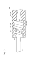
- FIG. 1 is an overall configuration diagram of a guiding catheter according to a first embodiment of the present invention.
- 2A is a partially omitted enlarged sectional view showing an initial state of the guiding catheter shown in FIG. 1
- FIG. 2B is a partially omitted enlarged side view showing a state in which the strain relief portion is contracted.
- It is a partially abbreviated expanded sectional view of a shaft part, a hub, and a strain relief part of a guiding catheter according to a second embodiment of the present invention.
- FIG. 4A is a partially omitted enlarged sectional view showing the initial state of the guiding catheter
- FIG. 4B shows the strain relief portion.
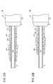
- FIG. 5A is a partially omitted enlarged side view showing the initial state of the guiding catheter
- FIG. 5B shows the strain relief portion.
- FIG. 6A is a partially omitted enlarged sectional view showing the initial state of the guiding catheter
- FIG. 6B shows the strain relief portion. It is a partially omitted enlarged cross-sectional view showing a contracted state.
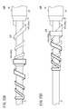
- FIG. 7A is a partially omitted enlarged side view showing the initial state of the guiding catheter
- FIG. 7B shows the strain relief portion. It is a partially omitted enlarged side view showing a contracted state. It is a partially omitted enlarged side view showing a modification of the guiding catheter according to the sixth embodiment of the present invention.
- FIG. 9A is a partially omitted enlarged side view showing the initial state of the guiding catheter
- FIG. 9B shows the strain relief portion. It is a partially omitted enlarged side view showing a contracted state.
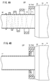
- FIG. 11 is a partially omitted enlarged sectional view of the shaft portion, hub, and strain relief portion shown in FIG. 11.
- FIG. 12A is a partially omitted enlarged sectional view showing an initial state of the guiding catheter
- FIG. 12B is a strain relief.
- FIG. 5 is a partially omitted enlarged cross-sectional view showing a state in which a part is stored in a storage chamber. It is a partially omitted enlarged sectional view showing a modification of the guiding catheter according to the eighth embodiment of the present invention.
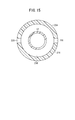
- FIG. 15 is a cross-sectional view taken along line XV-XV in FIG. 14.
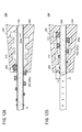
- FIG. 16A is a partially omitted enlarged sectional view showing the initial state of the guiding catheter
- FIG. 16B shows the strain relief portion. It is a partially omitted enlarged cross-sectional view showing a state of being stored in a storage chamber.
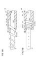
- FIG. 19A is a partially omitted enlarged sectional view showing an initial state of the guiding catheter
- FIG. 19A is a partially omitted enlarged cross-sectional view showing a state in which the protrusion amount of the second member relative to the member is reduced.
- FIG. 22A is a partially omitted enlarged sectional view showing an initial state of the guiding catheter
- FIG. 22B is for the first member. It is a partially omitted enlarged cross-sectional view showing a state in which the protruding amount of the second member is reduced.
- FIG. 23A is a partially omitted enlarged side view showing the initial state of the guiding catheter
- FIG. It is a partially omitted enlarged side view showing a state in which the protruding amount of the second member is reduced.
- FIG. 25A is a partially omitted enlarged sectional view showing an initial state of the guiding catheter
- FIG. 25B is for the first member.
- FIG. 26A is a partially omitted enlarged sectional view showing the initial state of the guiding catheter
- FIG. 26B is for the first member.
- FIG. 27A is a partially omitted enlarged sectional view showing the initial state of the guiding catheter
- FIG. 27A is a partially omitted enlarged sectional view showing the initial state of the guiding catheter
- FIG. 27B is a partially omitted enlarged cross-sectional view showing a state in which the protruding amount of the second member is reduced.
- a guiding catheter 10A according to the first embodiment (hereinafter also simply referred to as “catheter 10A”) will be described with reference to FIGS. 1 to 2B.
- This catheter 10A is inserted through a blood vessel (for example, aorta) that meanders the long shaft portion 12 through an insertion tool and the like, and after the distal end portion reaches an inlet of a coronary artery or the like, for example, the shaft portion 12 is inserted into the balloon catheter from the entrance of the coronary artery or the like to the stenosis portion generated in the coronary artery or the like, and the balloon is expanded at the stenosis portion to expand the stenosis portion and treat it. It is used for so-called PTCA (Percutaneous Transluminal Coronary Angioplasty).
- PTCA Percutaneous Transluminal Coronary Angioplasty
- the present invention also applies to catheters for improving and diagnosing lesions formed in living organs other than PTCA, such as other blood vessels, bile ducts, trachea, esophagus, urethra and other organs. Applicable.
- the catheter 10A includes a long and narrow shaft portion 12, a hub assembly 13, and a strain relief portion (anti-kink protector, breakage prevention portion, stress concentration avoidance portion or protection). It is also called a part.) 18 is provided.
- the hub assembly 13 is connected to the proximal end of the shaft portion 12, and the strain relief portion 18 is provided at the distal end of the hub assembly 13.
- the shaft portion 12 may extend to the inside (hollow portion) of the hub 14 described later that constitutes the hub assembly 13.
- the total length of the catheter 10A (the distance from the distal end of the shaft portion 12 to the rear end of the hub assembly 13) is set to, for example, 100 cm in consideration of operability.
- the total length of the catheter 10A may be arbitrarily set, and may be set, for example, in the range of 90 cm to 110 cm.
- the shaft portion 12 is formed in a cylindrical shape and is made of a highly slidable resin or the like, and a guide wire, a balloon catheter, or the like (not shown) for guiding the catheter 10A to the inlet of the coronary artery or the like is formed in the shaft portion 12. Is inserted.
- the shaft portion 12 has an appropriate flexibility and an appropriate strength so that the operator can smoothly insert it into a living organ such as a blood vessel while grasping and operating the proximal end side. Yes.
- the length of the shaft portion 12 is set based on the length of the blood vessel from the insertion position of the shaft portion 12 into the body to the entrance of the coronary artery or the like, and is set to 96 cm, for example. In addition, you may set the length of the shaft part 12 arbitrarily.
- the hub assembly 13 has a hub 14 and a connector 16.
- the hub 14 is made of resin or the like and has higher rigidity than the shaft portion 12.
- the hub 14 is formed in a hollow shape, and includes a hub body 20 and a tapered portion 22.
- the hub body 20 is formed in a cylindrical shape and connected to the connector 16.
- the outer peripheral portion of the cross section of the hub body 20 is not limited to a circle but may be a polygon or the like.
- the taper portion 22 is provided at the tip of the hub body 20 and has a diameter reduced toward the shaft portion 12.
- the connector 16 is made of a resin or the like, and includes an introduction portion 24 formed in a hollow shape and a pair of extension portions 26 and 26 protruding outward from the outer peripheral surface of the introduction portion 24. As a result, a guide wire or the like can be inserted into the introduction portion 24, the hub 14, and the shaft portion 12.
- the strain relief portion 18 has flexibility, and the belt body 18a fixed to the tip surface of the taper portion 22 is spirally wound around the shaft portion 12 a plurality of times (this embodiment). It is formed by winding 4 times in the form. As a result, the strain relief portion 18 is less rigid than the hub 14.
- the strain relief portion 18 is made of, for example, resin or metal.
- the separation interval (pitch) between the adjacent bands 18a is substantially constant. However, the spacing interval may be different. Further, the range of the shaft portion 12 around which the band 18a is wound, in other words, the range surrounded by the strain relief portion 18 of the shaft portion 12 can be arbitrarily set. It is set in the range of 8 cm from the base end.
- predetermined numbers and scales may be displayed on a portion surrounded by the strain relief portion 18 on the outer peripheral surface of the shaft portion 12.
- scales are displayed at 1 cm intervals in the axial direction of the shaft portion 12 (axial direction of the hub 14), and numbers from 0 to 8 correspond to the scales toward the hub 14 side. Is displayed.
- an auxiliary scale may be displayed at an intermediate position between the adjacent scales.
- numbers after 6 are not visually recognized by the strain relief portion 18.
- the strain relief portion 18 (band 18a) is gradually formed narrower and thinner toward the tip of the shaft portion 12.
- the inner surface of the strain relief portion 18 is slidably in contact with the outer peripheral surface of the shaft portion 12.
- An inner groove portion 28 having a substantially U-shaped cross section is formed on the inner surface of the strain relief portion 18. That is, the inner groove 28 extends in a spiral shape.
- the groove width of the inner groove portion 28 is set to about half the width of the band 18a, and as a result, gradually becomes narrower toward the tip end side of the shaft portion 12.
- the groove depth of the inner groove portion 28 is set to a depth of about 1/3 of the thickness of the band 18a, and as a result, gradually becomes shallower toward the distal end side of the shaft portion 12.
- the frictional resistance between the inner surface of the strain relief portion 18 and the outer peripheral surface of the shaft portion 12 is such that the operator can slide the strain relief portion 18 in the axial direction of the shaft portion 12 with one hand. That is, the strain relief portion 18 is configured to be extendable and contractible in the axial direction of the shaft portion 12.
- an outer groove portion 30 having a shape obtained by vertically inverting the inner groove portion 28 is formed on the outer surface of the strain relief portion 18. That is, the band 18a has a substantially H-shaped cross section by forming the inner groove 28 and the outer groove 30.
- the most advanced shape of the strain relief portion 18 is not particularly limited, but is preferably formed in an annular shape (closed ring). This is because, when the strain relief portion 18 is slid with respect to the outer peripheral surface of the shaft portion 12, the strain relief portion 18 can be preferably prevented from coming off from the shaft portion 12.
- a portion of the shaft portion 12 from the distal end of the shaft portion 12 to the distal end of the strain relief portion 18 can be inserted into the living body (intravascular) from the proximal end portion of the insertion tool. It becomes.
- the length from the tip of the shaft portion 12 to the tip of the strain relief portion 18 is referred to as the effective length of the shaft portion 12.
- the form of a stenosis in a living organ such as a coronary artery is specified by an intravascular imaging method or an intravascular ultrasonic diagnostic method.
- a guide wire (not shown) is introduced into the blood vessel percutaneously from the thigh or the like by the Seldinger method, and the shaft portion 12 of the catheter 10A is placed along the guide wire. Is inserted into the living organ.
- a guide wire (not shown) is advanced to the entrance of the coronary artery and the like, passed through the entrance and placed inside the coronary artery and the like, and the shaft portion 12 advances along the guide wire into the living organ. Let Subsequently, after the distal end of the shaft portion 12 reaches the entrance of the coronary artery or the like, the guide wire is removed from the catheter 10A.
- the tip of the strain relief 18 may hit the insertion tool (or skin). That is, the effective length of the shaft portion 12 may be insufficient, and the tip of the shaft portion 12 may not reach the entrance of the coronary artery or the like.
- the operator confirms the short distance between the distal end of the shaft portion 12 and the entrance of the coronary artery or the like under fluoroscopy. For example, when the short distance is about 3 cm, the tip of the strain relief portion 18 is moved to the proximal end side of the shaft portion 12 while sliding the strain relief portion 18 with respect to the outer peripheral surface of the shaft portion 12. Draw. As a result, the strain relief portion 18 contracts in the axial direction of the shaft portion 12 when the spacing between the adjacent band members 18a becomes narrow (or the adjacent band members 18a come into contact with each other).
- the tip of the strain relief portion 18 is positioned in the vicinity of the 5 cm scale displayed on the outer peripheral surface of the shaft portion 12 (see FIG. 2B). Thereby, the effective length of the shaft part 12 will be extended about 5 cm.
- the shaft portion 12 in this state is further advanced into the living organ by a short distance, whereby the tip of the shaft portion 12 is placed at the entrance of the coronary artery or the like.
- the shaft portion 12 when the shaft portion 12 is further advanced into the living organ with the effective length of the shaft portion 12 extended, as a result, when the tip of the shaft portion 12 passes through the entrance of the coronary artery or the like, the shaft portion 12
- the strain relief 18 may be slightly extended while pulling back toward the front. Thereby, since the restoring force of the strain relief part 18 becomes small, the surgeon can maintain the contracted state of the strain relief part 18 without applying excessive force.
- the strain relief portion 18 is contracted (the tip of the strain relief portion 18 is displaced to the side where the hub 14 is located).
- the effective length of the shaft portion 12 is extended.
- the groove widths of the inner groove portion 28 and the outer groove portion 30 are gradually narrowed toward the tip end side of the shaft portion 12, and the groove depths of the inner groove portion 28 and the outer groove portion 30 are the shaft portions 12. Since it gradually becomes shallower toward the distal end side of the shaft, the shaft 18a toward the distal end side of the shaft portion 12 even when the adjacent band bodies 18a come into contact with each other when the strain relief portion 18 is contracted. The flexibility of the portion 12 can be gradually increased. Thereby, the kink resistance can be appropriately exerted on the proximal end side of the shaft portion 12 in a state where the strain relief portion 18 is contracted.
- the groove width and groove depth of the inner groove portion 28 and the outer groove portion 30 can be arbitrarily set.
- the groove widths of the inner groove portion 28 and the outer groove portion 30 may be, for example, about 1/3 of the width of the band 18a, or about 3/4 of the width of the band 18a.
- the groove depths of the inner groove portion 28 and the outer groove portion 30 may be less than 1/3 of the thickness of the band 18a.
- cross-sectional shapes of the inner groove portion 28 and the outer groove portion 30 are not limited to a substantially U-shaped cross section, and can be any shape.
- At least one of the inner groove portion 28 and the outer groove portion 30 may be omitted.
- the strain relief portion 18 may be non-contact with the shaft portion 12. In this case, if the outer peripheral surface of the shaft portion 12 and the strain relief portion 18 can come into contact with each other when the proximal end side of the shaft portion 12 is deformed, kink resistance can be exerted on the proximal end side of the shaft portion 12. it can.
- the number displayed on the outer peripheral surface of the shaft portion 12 may be a number corresponding to the distance from the tip of the shaft portion 12 to the tip of the strain relief portion 18. In this case, the effective length of the extended shaft portion 12 can be easily known.
- a guiding catheter 10B (hereinafter also referred to as “catheter 10B”) according to a second embodiment of the present invention will be described with reference to FIG.
- catheter 10B which concerns on 2nd Embodiment
- the same referential mark is attached
- the catheter 10B is different from the catheter 10A according to the first embodiment in the configuration of the strain relief portion 32.
- the strain relief portion 32 is formed in a hollow shape. That is, the strain relief portion 32 is formed with a hole 34 having a substantially rectangular cross section.
- the inner groove portion 28 and the outer groove portion 30 of the first embodiment are omitted, and the same applies to the third to eighth embodiments.
- the strain relief portion 32 is formed in a hollow shape, even if the strain relief portion 32 is contracted and adjacent band bodies 32a contact each other, the strain relief portion 32 is formed.
- the relief part 32 can be easily elastically deformed. Therefore, kink resistance can be suitably exhibited on the proximal end side of the shaft portion 12.
- the cross-sectional shape of the hole 34 of the strain relief portion 32 is not limited to a substantially rectangular cross-section, and can be any shape.
- the cross-sectional shape of the hole 34 may be, for example, a substantially circular cross section.
- a guiding catheter 10C (hereinafter also referred to as “catheter 10C”) according to a third embodiment of the present invention will be described with reference to FIGS. 4A and 4B.
- the catheter 10C is different from the catheter 10A according to the first embodiment in the configuration of the strain relief portion 36.
- the strain relief portion 36 has a tip portion in contact with the outer peripheral surface of the shaft portion 12, and a portion other than the tip portion of the strain relief portion 36 is not in contact with the outer peripheral surface of the shaft portion 12. ing.
- the distance L1 between the inner surface of the band body 36a located on the proximal end side of the shaft section 12 and the shaft section 12 is equal to the outer surface of the band body 36a positioned on the distal end side of the shaft section 12 and the shaft. It is set wider than the interval L2 of the part 12.
- FIGS. 5A and 5B a guiding catheter 10D (hereinafter also referred to as “catheter 10D”) according to a fourth embodiment of the present invention will be described with reference to FIGS. 5A and 5B.
- the numerals and scales (see FIG. 2B) of the shaft portion 12 described above are omitted, but the numbers and scales are actually displayed on the shaft portion 12. The same applies to FIGS. 7A to 10.
- the catheter 10D is different from the catheter 10A according to the first embodiment in the configuration of the strain relief portion 38 and the hub 40.
- a plurality of (four in FIG. 5A) convex portions projecting toward the hub 40 (in the axial direction of the shaft portion 12) on one side surface (the base end side of the shaft portion 12) of the strain relief portion 38. 42a to 42d are formed. These convex portions 42 a to 42 d are offset in the circumferential direction of the shaft portion 12.
- Each of the convex portions 42a to 42d is formed in a substantially square shape when viewed from the side, and gradually increases in width toward the protruding direction.
- a plurality of (three in FIG. 5A) concave portions 44a to 44c corresponding to the convex portions 42a to 42c are formed on the side surface of the other side of the strain relief portion 38 (the tip side of the shaft portion 12).
- Each of the concave portions 44a to 44c is slightly offset in the circumferential direction of the shaft portion 12 from the position where the convex portions 42a to 42c face each other.
- the hub 40 has a hub body 20 and a tapered portion 46, and a concave portion 48 having substantially the same shape as the concave portions 44a to 44c is formed at the tip of the tapered portion 46.
- the concave portion 48 faces the convex portion 42d.
- the convex portion 42d positioned closest to the hub 40 is elastically deformed and the concave portion 48 and the other convex portions 42a to 42c elastically deform and enter the concave portions 44a to 44c.
- the contraction operation of the strain relief portion 38 and the operation for locking the contraction state can be performed with one touch.
- the number and shape of the convex portions 42a to 42d and the concave portions 44a to 44c, 48 may be arbitrarily set. In short, a predetermined frictional force may be generated when the convex portions 42a to 42d and the concave portions 44a to 44c and 48 are engaged.
- a guiding catheter 10E (hereinafter also referred to as “catheter 10E”) according to a fifth embodiment of the present invention will be described with reference to FIGS. 6A and 6B.
- the catheter 10E differs from the catheter 10A according to the first embodiment in the configuration of the strain relief portion 50.
- the strain relief portion 50 includes a first portion 52 that is located on the most proximal side of the shaft portion 12 and has a substantially trapezoidal cross section, an intermediate portion 54 that is continuous with the first portion 52, and a shaft.
- a second portion 56 that is located on the most distal end side of the portion 12 and continues to the intermediate portion 54 is included.
- the first portion 52 is wound only once in a spiral around the shaft portion 12.
- the side surface of the first portion 52 on the distal end side of the shaft portion 12 is formed in a tapered shape that gradually decreases in diameter toward the distal end side.
- a first notch 58 is formed in a portion of the side surface adjacent to the shaft portion 12.
- the intermediate portion 54 is spirally wound around the shaft portion 12 only twice.
- the intermediate portion 54 is provided on the first inner portion 60 formed in a substantially parallelogram shape in cross section in contact with the outer peripheral surface of the shaft portion 12, and on a part of the outer surface of the first inner portion 60, and has an approximately cross section.
- a first outer portion 62 formed in a parallelogram shape. The first outer portion 62 protrudes toward the distal end side of the shaft portion 12 with respect to the first inner portion 60.
- the shape of the end portion of the protrusion (convex portion) 60 a corresponds to the shape of the first cutout portion 58.
- the protruding amount of the protruding portion 60a is set to be larger than the length of the first cutout portion 58 in the axial direction of the shaft portion 12.
- the intermediate portion 54 includes a second portion of the first outer portion 62 that protrudes toward the distal end side of the shaft portion 12 with respect to the first inner portion 60 and the other end portion of the first inner portion 60.
- a notch (recess) 64 is formed. Note that the second cutout portion 64 has substantially the same shape as the first cutout portion 58.
- the second portion 56 is wound only once in a spiral around the shaft portion 12.
- the second portion 56 is provided in a part of the outer surface of the second inner portion 66 and the second inner portion 66 formed in a substantially trapezoidal cross section in contact with the outer peripheral surface of the shaft portion 12, and has a substantially square cross section.
- a second outer portion 68 formed in a shape. Further, the second outer portion 68 is located at the tip of the strain relief portion 50.
- the protruding portion 60a of the intermediate portion 54 is elastically deformed while part of the protruding portion 60a is elastically deformed. While entering one notch 58, the other part of the protrusion 60a is elastically deformed and partially enters the second notch 64, and the end of the second inner portion 66 on the hub 14 side is elastically deformed. The other part of the second notch 64 is inserted.
- a predetermined frictional force is generated between the projecting portion 60a and the first notch portion 58, between the projecting portion 60a and the second notch portion 64, and between the second inner portion 66 and the second notch portion 64.
- the relief part 50 is locked in a contracted state.
- a first gap 70 is formed between the first portion 52 and the first outer portion 62
- a second gap 72 and a third gap 74 are formed between the adjacent first outer portions 62
- the first outer portion 62 is formed between the first outer portion 62
- the fourth gap 76 is formed between the second outer portion 68 and the second outer portion 68. Accordingly, since the strain relief portion 50 can be easily elastically deformed along the bending deformation of the shaft portion 12 in a state in which the strain relief portion 50 is contracted, kink resistance is improved on the proximal end side of the shaft portion 12. It can be exhibited effectively.
- the shapes of the protruding portion 60a, the first cutout portion 58, the second cutout portion 64, and the second inner portion 66 may be arbitrarily set.
- the protrusion 60a is formed wider toward the hub 14 side
- the end of the second inner portion 66 on the hub 14 side has the same shape as the protrusion 60a
- the first and second notches The shapes of the portions 58 and 64 may correspond to the shape of the end portion of the protruding portion 60a. In this case, it becomes difficult to unlock the strain relief portion 50 in the contracted state.
- a guiding catheter 10F (hereinafter also referred to as “catheter 10F”) according to a sixth embodiment of the present invention will be described with reference to FIGS. 7A to 8.
- this catheter 10F is different from the catheter 10A according to the first embodiment in the configuration of the shaft portion 78 and the strain relief portion 80.
- the guiding catheter 10F is positioned closer to the hub 14 than the distal end of the strain relief portion 80 in the initial state (the strain relief portion 18 is extended), and the shaft A protrusion 82 protruding outward in the radial direction of the portion 78 is formed.
- the protrusion 82 is formed in an annular shape on the outer peripheral surface of the shaft portion 78.
- the protrusion 82 is located slightly on the base end side of the portion surrounded by the strain relief portion 80 of the shaft portion 78.
- the projecting portion 82 can be disposed at an arbitrary position of a portion surrounded by the strain relief portion 80 of the shaft portion 78.
- the height (projection amount) of the protruding portion 82 is set to a height that allows the protruding portion 82 to get over in a state where the strain relief portion 80 is bent.
- the distal end of the strain relief portion 80 gets over the protruding portion 82 by pulling the strain relief portion 80 toward the proximal end side of the shaft portion 78.
- the contracted state can be locked while the relief portion 80 is contracted. Thereby, the contraction operation of the strain relief portion 80 and the operation of locking the contraction state can be performed with one touch.
- the protruding portion 82 is formed in an annular shape on the outer peripheral surface of the shaft portion 78, the strain relief portion 80 overcoming the protruding portion 82 causes the protruding portion 82 to be moved by a restoring force (spring action). Overcoming again can be suitably suppressed.
- the projecting portion 82 includes a first taper portion 84 whose diameter increases toward the proximal end in the axial direction of the shaft portion 78, and a shaft that is continuous with the first taper portion 84 and the shaft. You may have the 2nd taper part 86 diameter-reduced toward the base end side in the axial direction of the part 78.
- the strain relief portion 80 when the strain relief portion 80 is pulled toward the hub 14, the strain relief portion 80 can be smoothly slid with respect to the first taper portion 84. Further, by providing the second taper portion 86, the strain relief portion 80 can be smoothly slid with respect to the second taper portion 86 when the strain relief portion 80 in the contracted state is extended. In this modification, the second taper portion 86 may be omitted.
- the configuration of the protrusion 82 is not limited to an annular shape, and may take any shape.
- the protrusion 82 may be formed in an arc shape or a rectangular shape on the outer peripheral surface of the shaft portion 78.
- the catheter 10F according to the present embodiment may be provided with a plurality of protrusions 82 on the outer peripheral surface of the shaft portion 78.
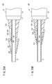
- a guiding catheter 10G (hereinafter also referred to as “catheter 10G”) according to a seventh embodiment of the present invention will be described with reference to FIGS. 9A to 10.
- this catheter 10G is different from the catheter 10A according to the first embodiment in the configuration of the hub 88 and the strain relief portion.
- the hub 88 includes a hub body 90 formed slightly larger than the hub body 20 of the first embodiment, and a lock mechanism 92 provided on the hub body 90.
- the tapered portion 22 of the first embodiment is omitted.
- a hole portion 94 extending in the axial direction of the shaft portion 12 is formed on the front end surface of the hub main body 90, and a long hole 96 communicating with the hole portion 94 is formed on the outer peripheral surface of the hub main body 90.
- the depth of the hole 94 is set to a depth slightly shorter than the length of the lock member 100 described later.
- the hole portion 94 may pass through the hub body 90.
- first engagement teeth 98 are provided continuously on the wall surface of the hole portion 94 in the depth direction of the hole portion 94.
- the range in which the first engagement teeth 98 are formed may be arbitrarily determined.
- Each first engagement tooth 98 is formed in a substantially triangular cross section, a tooth surface 98a located on the tip side forms the long side of the triangle, and a tooth surface 98b located on the connector 16 side has a short side of the triangle. Is forming.
- the lock mechanism 92 extends in one direction and is provided in the hole 94 of the hub body 90 and has flexibility, and a lock release lever provided in the vicinity of one end of the lock member 100. 102.
- a part of the lock member 100 is inserted into the hole 94, and the other part is located outside the hole 94.
- a contact portion 104 that protrudes toward the shaft portion 12 is formed at the other end of the lock member 100 (the side located outside the hole portion 94).
- the surface of the contact portion 104 that faces the hub body 90 is formed in a tapered shape that gradually increases in width toward the protruding direction of the contact portion 104.
- the outer diameter of the lock member 100 is formed to be somewhat smaller than the hole diameter of the hole portion 94.
- a plurality of second engagement teeth 106 that can be engaged with the first engagement teeth 98 are formed at a portion from the other end of the lock member 100 to a position slightly beyond the center and the tip. Accordingly, the second engagement teeth 106 are always engaged with the first engagement teeth 98 regardless of the position of the lock member 100.
- Each of the second engaging teeth 106 has a substantially triangular cross section, a tooth surface 106a located on the distal end side forms a short side of the triangle, and a tooth surface 106b located on the connector 16 side has a triangular shape. The long side is formed.
- the lock member 100 has a force necessary to move the lock member 100 toward the distal end side of the shaft portion 12 in a state where the first and second engagement teeth 98 and 106 are engaged (engaged) with each other.
- the force required to move the lock member 100 toward the connector 16 is larger. That is, the lock member 100 is less likely to move to the distal end side of the shaft portion 12 and is easier to move to the connector 16 side (base end side).
- the number of teeth of the first engagement teeth 98 and the shape of the first and second engagement teeth 98 and 106 are determined when the restoring force when the strain relief 108 contracts acts on the lock member 100.
- the number of teeth and the shape are set so that the member 100 does not move to the distal end side of the shaft portion 12.
- a tapered surface 110 corresponding to the tapered surface 104 a of the contact portion 104 is formed at the distal end portion of the strain relief portion 108. Further, the lock release lever 102 is exposed to the outside of the hub body 90 through the long hole 96.
- the second engagement teeth 106 get over the first engagement teeth 98, so that the lock member 100 is moved toward the connector 16 side.
- the tapered surface 104a of the contact portion 104 moves and contacts the tapered surface 110 at the tip of the strain relief portion.
- the strain relief portion 108 is contracted as shown in FIG. 9B.
- the contracted state can be locked in a state where the strain relief portion 108 is contracted. Thereby, the contracting operation of the strain relief portion 108 and the operation of locking the contracted state can be performed with one touch.
- the engagement state of the first and second engagement teeth 98 and 106 is released by pulling up the lock release lever 102, so that the lock member 100 can be easily attached to the shaft. It can be moved to the tip side of the part 12.
- the strain relief portion 108 can be arbitrarily contracted. Can be locked in state.
- the catheter 10G according to the present embodiment is not limited to the configuration described above.
- the lock member 100 may be fixed to the distal end surface of the hub body 90. In this case, by pulling the strain relief portion 108 toward the hub body 90 and positioning the distal end of the strain relief portion 108 closer to the hub body 90 than the contact portion 104, the contracted state of the strain relief portion 108 is suitably locked. can do.
- the contact portion 104 may be formed in a rectangular shape when viewed from the side.
- a guiding catheter 10H (hereinafter also referred to as “catheter 10H”) according to an eighth embodiment of the invention will be described with reference to FIGS.
- the catheter 10H is different from the catheter 10A according to the first embodiment in the configuration of the strain relief portion 200 and the hub assembly 201.
- the hub assembly 201 is provided so as to surround the proximal end portion of the shaft portion 12 (see FIG. 12A), and includes the hub 202 and the connector 16.
- tip of the hub 202 is set, for example to 5 cm.
- predetermined numbers and scales are displayed on the outer peripheral surface of the shaft portion 12 between the tip of the strain relief portion 200 and the tip of the hub 202.
- scales are displayed at intervals of 1 cm in the axial direction of the shaft portion 12 (axial direction of the hub 202), and numbers from 0 to 5 correspond to the scales toward the hub 202 side. Is displayed.
- an auxiliary scale is displayed at an intermediate position between the adjacent scales.
- the hub 202 is formed in a taper shape so that the diameter is gradually reduced toward the distal end side of the shaft portion 12.
- the hub 202 includes a first part 204 connected to the connector 16 and a second part 206 provided at the tip of the first part 204 and provided with a strain relief portion 200.
- a through hole 208 is formed in the first portion 204 along the axial direction of the shaft portion 12. And the base end part of the shaft part 12 is being fixed to the 1st site
- the second portion 206 is formed in a cylindrical shape, and protrudes from the distal end surface 204a of the first portion 204 toward the distal end side of the shaft portion 12. That is, the second portion 206 surrounds a part of the proximal end side of the shaft portion 12.
- the outer peripheral surface of the first portion 204 and the outer peripheral surface of the second portion 206 are integrated and form a continuous tapered surface that is reduced in diameter toward the distal end side of the shaft portion 12.
- the inner peripheral surface of the second portion 206 is formed in a tapered shape that decreases in diameter toward the distal end side of the shaft portion 12 in a state of being separated from the shaft portion 12.
- the taper angle of the outer peripheral surface and the taper angle of the inner peripheral surface are set to be substantially the same.
- a spiral groove 210 is formed on the inner peripheral surface of the second portion 206 along the axial direction of the shaft portion 12. As a result, the spiral groove 210 extends outward in the radial direction of the shaft portion 12 toward the first portion 204.
- the spiral groove 210 is formed in a rectangular cross section and has three rounds around the shaft portion 12.
- the pitch of the spiral groove 210 corresponds to the spiral pitch of the strain relief portion 200 described above.
- the groove width and groove depth of the spiral groove 210 are set constant. Specifically, the groove width of the spiral groove 210 is slightly larger than the width of the band 200a located at the base end portion (rear end portion) of the strain relief portion 200, and the groove depth of the spiral groove 210 is This is shallower than the thickness of the band 200a.
- the gap L3 between the groove bottom surface and the shaft portion 12 is determined by the thickness of the band body 200a located at the proximal end portion of the strain relief portion 200. Is also set slightly smaller (see also FIG. 12B).
- the proximal end portion of the strain relief portion 200 is disposed at the start end portion of the spiral groove 210 in a bent state. Thereby, it is possible to prevent the strain relief portion 200 from coming out of the spiral groove 210 and separating the strain relief portion 200 and the hub 202 from each other. That is, the starting end portion of the spiral groove 210 functions as a separation preventing mechanism.
- the inner peripheral surface of the second part 206 terminates at the tip surface 204a of the first part 204.
- the storage chamber 212 is formed by the tip surface 204 a of the first part 204 and the inner peripheral surface of the second part 206.
- the storage chamber 212 communicates with the through hole 208 and opens to the distal end side of the shaft portion 12.
- the strain relief 200 is rotated into the spiral groove 210 by rotating the strain relief 200 clockwise as viewed from the proximal end side of the catheter 10H.
- the storage chamber 212 can be entered while being engaged.
- the effective length of the shaft portion 12 can be extended by displacing the tip of the strain relief portion 200 toward the hub 202 side.
- the strain relief portion 200 stored in the storage chamber 212 is changed to the shaft portion. Since it can be elastically deformed along 12 bending deformations, kink resistance can be suitably exhibited on the proximal end side of the shaft portion 12.
- the strain relief portion 200 is rotated to enter the storage chamber 212 while engaging the spiral groove 210 with the rotation of the strain relief portion 200. Therefore, the rotation amount of the strain relief portion 200 is increased. By adjusting this, the amount of extension of the effective length of the shaft portion 12 can be arbitrarily set.
- the base end portion of the strain relief portion 200 is the first portion 204.
- the distal end portion of the strain relief portion 200 can be disposed so as to protrude from the distal end of the second portion 206 while being in contact with the distal end surface 204a. As a result, it is possible to suitably prevent the strain relief portion 200 from entering the storage chamber 212 excessively, so that the strain relief portion 200 stored in the storage chamber 212 can be easily taken out of the storage chamber 212. .
- the strain relief portion 200 is gradually narrowed toward the distal end side of the shaft portion 12, the flexibility of the shaft portion 12 is increased from the proximal end portion of the shaft portion 12 toward the distal end. Can be increased. Thereby, kink resistance can be suitably exhibited in the base end side of the shaft part 12.
- the hub 202 may not be fixed to the shaft portion 12 as in the catheter 10H according to the modification shown in FIG. That is, the hub 202 may be provided so as to be rotatable with respect to the shaft portion 12.
- the annular convex portion 214 may be formed on the outer peripheral surface of the shaft portion 12, and the annular concave portion 216 in which the annular convex portion 214 can be disposed may be formed on the wall surface of the through hole 208.
- the hub 202 is rotatable with respect to the shaft portion 12 in a state where movement of the shaft portion 12 in the axial direction is restricted.
- the operator rotates the hub 202 in a clockwise direction when viewed from the proximal end side direction of the catheter 10H while holding the strain relief portion 200, so that the strain relief portion 200 is inserted into the spiral groove 210. It is possible to enter the storage chamber 212 while being engaged. Accordingly, the effective length of the shaft portion 12 can be extended by operating the hub 202 while preventing the shaft portion 12 from rotating. As a result, when the strain relief portion 200 enters the storage chamber 212, even when the portion of the strain relief portion 200 exposed from the tip of the second portion 206 becomes small, the storage of the strain relief portion 200 is possible. The entry into the chamber 212 can be performed reliably and easily.
- the annular convex portion 214 is formed in a substantially square cross section, and the annular concave portion 216 is formed in a rectangular cross section, but the sectional shapes of the annular convex portion 214 and the annular concave portion 216 are arbitrarily set. be able to. Also, the sizes of the annular convex portion 214 and the annular concave portion 216 can be arbitrarily set.
- the spiral pitch of the strain relief portion 200 and the spiral pitch of the spiral groove 210 can be arbitrarily changed. Since the strain relief portion 200 has flexibility and can be expanded and contracted, the strain relief portion 200 can be engaged with the spiral groove 210 even if the pitch is slightly shifted.
- the number of spiral turns of the strain relief portion 200 and the number of spiral turns of the spiral groove 210 can be arbitrarily set.
- the most advanced shape of the strain relief part 200 (band body 200a) is not particularly limited, it is preferably formed in an annular shape (closed ring). By doing so, it is possible to suitably prevent the strain relief portion 200 from being detached from the shaft portion 12 when the strain relief portion 200 is stored in the storage chamber 212 or taken out of the storage chamber 212. is there.
- the number displayed on the outer peripheral surface of the shaft portion 12 may be a number corresponding to the distance from the tip of the shaft portion 12 to the tip of the strain relief portion 200.
- the effective length of the extended shaft portion 12 can be easily known.
- a guiding catheter 10I (hereinafter also referred to as “catheter 10I”) according to a ninth embodiment of the present invention will be described with reference to FIGS. 14 to 16B.
- catheter 10I which concerns on 9th Embodiment
- the same referential mark is attached
- the catheter 10I is different from the catheter 10H according to the eighth embodiment in the configuration of the hub 218.
- the hub 218 is formed in a cylindrical shape, and its diameter is substantially constant.
- the outer peripheral section of the hub 218 is not limited to a circle but may be a polygon or the like.
- the hub 218 includes a first part 220 connected to the connector 16 and a second part 222 provided at the tip of the first part 220.
- the second portion 222 is formed in a cylindrical shape, and protrudes from the distal end surface 220a of the first portion 220 toward the distal end side of the shaft portion 12, and the distal end of the protruding portion 224. And a stopper portion 226 protruding from the shaft portion 12 side.
- the second portion 222 surrounds a part of the shaft portion 12.
- the outer peripheral surface of the first portion 220 and the outer peripheral surface of the protrusion 224 are integrally connected to form the outer peripheral surface of the hub 218.
- the protrusion 224 is formed with a pair of slits 228 and 228 extending in the axial direction of the shaft portion 12 (see FIGS. 14 and 15). These slits 228 and 228 are opposed to each other across the axis of the shaft portion 12. In other words, the slits 228 and 228 are arranged at equal intervals in the circumferential direction of the protrusion 224.
- each slit 228 reaches the tip of the protrusion 224.
- the other end of each slit 228 is rounded and is located near the rear end of the protrusion 224.
- the width of each slit 228 is set to about 1/3 of the diameter of the shaft portion 12. The length and width of the slit 228 can be arbitrarily set.
- the stopper portion 226 and the shaft portion 12 are separated from each other, and the separation interval is set smaller than the thickness of the tip of the strain relief portion 200. Further, a tapered surface 226 a that becomes narrower toward the shaft portion 12 is formed on the outer surface of the tip portion of the stopper portion 226.
- the front end surface 220a of the first portion 220 and the inner surface of the stopper portion 226 terminate at the inner peripheral surface of the protruding portion 224.
- the storage chamber 230 is formed by the front end surface 220 a of the first portion 220, the inner peripheral surface of the protruding portion 224, and the inner surface of the stopper portion 226.
- the storage chamber 230 communicates with the through hole 208 and opens to the distal end side of the shaft portion 12.
- the storage chamber 230 is set to a size that can store the strain relief portion 200 in a contracted state.
- the stopper portion 226 formed with the tapered surface 226a. Therefore, it can prevent that the strain relief part 200 and the hub 218 isolate
- the strain relief portion 200 when the strain relief portion 200 is pulled toward the connector 16, the strain relief portion 200 contacts the tapered surface 226a of the stopper portion 226, and the stopper portion 226 is in the radial direction of the shaft portion 12. Pressed outward.
- the strain relief portion 200 receives a reaction force from the stopper portion 226, and thus is slightly elastically deformed (contracted) inward in the radial direction of the shaft portion 12. And the strain relief part 200 drawn near to the connector 16 side is guide
- the strain relief portion 200 guided to the storage chamber 230 comes into contact with the distal end surface 220a of the first portion 220, so that the interval between the adjacent band bodies 200a is shortened and contracted. . Thereby, the strain relief part 200 becomes compact in the state accommodated in the storage chamber 230.
- the length of the hub 218 is sufficiently larger than the length of the strain relief portion 200 (the length in the axial direction of the shaft portion 12) in the initial catheter 10I. Even a catheter that cannot be set for a long time can be handled.
- the strain relief portion 200 housed in the storage chamber 230 since the strain relief portion 200 housed in the storage chamber 230 is in a contracted state, the strain relief portion 200 tries to return to its original state (try to stretch) by a restoring force (action of a spring). Since the tip of the portion 200 is locked to the stopper portion 226, the strain relief portion 200 can be suitably prevented from coming out of the opening of the storage chamber 230.
- the protruding portion 224 is not limited to the configuration in which the pair of slits 228 and 228 are formed.
- three or more slits 228 may be formed in the protrusion 224.
- the slits 228 are preferably arranged at equal intervals in the circumferential direction of the protruding portion 224. This is because the opening of the storage chamber 230 can be expanded in a balanced manner.
- a guiding catheter 10J (hereinafter also referred to as “catheter 10J”) according to a tenth embodiment of the present invention will be described with reference to FIG.
- the same referential mark is attached
- the numerals and scales (see FIG. 12B) of the shaft portion 12 described above are omitted, but the numbers and scales are actually displayed on the shaft portion 12.
- this catheter 10J is different from the catheter 10I according to the ninth embodiment in the configuration of the second portion 234 of the hub 232.
- the second portion 234 is formed in a cylindrical shape, and has a protruding portion 236 that protrudes from the distal end surface 220a of the first portion 220 toward the distal end side of the shaft portion 12, and the stopper of the ninth embodiment.
- the part 226 is omitted.
- a spiral protrusion 238 is formed at a position slightly closer to the tip of the inner peripheral surface of the protrusion 236.
- the projecting portion 238 makes one round around the shaft portion 12.
- the distance between the start end and the end end of the protrusion 238 is set slightly smaller than the width of the base end of the strain relief portion 200.
- the protruding portion 238 and the shaft portion 12 are separated from each other, and the separation interval is set smaller than the thickness of the tip of the strain relief portion 200.
- the opposing surface of the protrusion 238 that faces the distal end surface 220a of the first portion 220 and the distal end surface 220a of the first portion 220 terminate at the inner peripheral surface of the protruding portion 236.
- the storage chamber 240 is formed by the front end surface 220 a of the first portion 220, the facing surface of the protruding portion 238, and the inner peripheral surface of the protruding portion 236.
- the storage chamber 240 communicates with the through hole 208 and opens to the distal end side of the shaft portion 12.
- the operator causes the strain relief portion 200 to enter the storage chamber 240 by rotating the strain relief portion 200 counterclockwise while holding the hub 232. Can do. Then, the strain relief portion 200 that has entered the storage chamber 240 is contracted by coming into contact with the distal end surface 220 a of the first portion 220. Thereby, the strain relief part 200 can be stored compactly in the storage chamber 240, and the amount of extension of the effective length of the shaft part 12 can be arbitrarily set by adjusting the amount of rotation of the strain relief part 200. it can.
- At least one of the inner groove portion 28 and the outer groove portion 30 of the first embodiment may be formed in the strain relief portions 36, 38, 50, 80, 108, 200. Moreover, it may be formed in a hollow shape like the strain relief portion 32 of the second embodiment. Thereby, even when the strain relief portions 36, 38, 50, 80, 108, 200 are contracted, the kink resistance on the proximal end side of the shaft portions 12, 78 can be appropriately exhibited.
- the strain relief portions 18, 32, 36, 38, 50, 80, 108, 200 are the band bodies 18a, 32a, 36a, 38a, 50a, 80a, having a certain width.
- 108a and 200a may be formed by spirally winding around the shaft portions 12 and 78.
- the most advanced shape of the band members 18a, 32a, 36a, 38a, 50a, 80a, 108a, and 200a is not particularly limited, but it is preferably formed in an annular shape (closed ring).
- strain relief parts 18, 32, 36, 38, 50, 80, 108, 200 are contracted (stretched), it is possible to suitably prevent the strain relief parts 18, 32, 36, 38, 50, 80, 108, 200 from coming off the shaft parts 12, 78.
- a guiding catheter 10K (hereinafter, also referred to as “catheter 10K”) according to an eleventh embodiment of the present invention will be described with reference to FIGS.
- catheter 10K which concerns on 11th Embodiment
- the same referential mark is attached
- the catheter 10K is different from the catheter 10A according to the first embodiment in the configuration of the strain relief portion 300.
- the range surrounding the shaft portion 12 in the strain relief portion 300 is set to 12 cm, for example.
- the strain relief portion 300 includes a first member 302 fixed to the tip of the taper portion 22 and a second member 304 provided on the first member 302 in a state of being positioned on the tip side of the first member 302. Have.
- the first member 302 is formed in a cylindrical shape and is gradually tapered toward the tip side of the shaft portion 12. As a result, the first member 302 is less rigid than the hub 14. The inner peripheral surface of the first member 302 is in contact with the outer peripheral surface of the shaft portion 12.
- a first outer convex portion 306a and a second outer convex portion 306b positioned closer to the distal end side than the first outer convex portion 306a are provided at a predetermined portion of the first member 302 located on the distal end side from the approximate center of the outer peripheral surface.
- the first to third outer convex portions 306 a to 306 c are formed in an annular shape on the outer peripheral surface of the first member 302.
- the spacing between the first outer convex portion 306a and the second outer convex portion 306b and the spacing interval between the second outer convex portion 306b and the third outer convex portion 306c can be arbitrarily set, but are set substantially the same. .
- Each of the first to third outer convex portions 306a to 306c has a triangular cross section.
- the cross-sectional area of the second outer convex portion 306b is smaller than the cross-sectional area of the first outer convex portion 306a, and the cross-sectional area of the third outer convex portion 306c is set smaller than the cross-sectional area of the second outer convex portion 306b.
- the second member 304 is formed in a cylindrical shape and is formed in a tapered shape that gradually tapers toward the distal end side of the shaft portion 12. Accordingly, the rigidity of the second member 304 is lower than that of the hub 14.
- the second member 304 is configured so that its inner diameter gradually increases as it goes toward the hub 14 side. That is, the inner peripheral surface of the second member 304 is formed in a tapered shape.
- the taper angle of the inner peripheral surface of the second member 304 and the taper angle of the outer peripheral surface of the first member 302 are set to be substantially the same.
- the second member 304 is disposed such that the distal end thereof is in contact with the outer peripheral surface of the shaft portion 12 and the proximal end portion surrounds a predetermined range on the distal end side of the first member 302. In short, the tip of the second member 304 protrudes further toward the tip than the tip of the first member 302.
- the protrusion amount L4 of the second member 304 relative to the first member 302, in other words, the distance from the tip of the first member 302 to the tip of the second member 304 can be arbitrarily set, but is set to 5 cm, for example.
- predetermined numbers and scales as display means are displayed on the outer peripheral surface of the shaft portion 12 surrounded by only the second member 304.
- scales are displayed at intervals of 1 cm in the axial direction of the shaft portion 12, and numbers from 0 to 5 are displayed corresponding to the scales toward the hub 14 side.
- an auxiliary scale is displayed at an intermediate position between the adjacent scales.
- a scale including an auxiliary scale
- a number is displayed by appending to the scale, it is not necessary to display this number in the same way as the scale.
- a first inner convex portion 308a Near the center of the inner peripheral surface of the second member 304, a first inner convex portion 308a, a second inner convex portion 308b positioned on the tip side of the first inner convex portion 308a, and the second inner convex portion.
- the third inner convex portion 308c located on the tip side of the portion 308b is formed in a separated state.
- Each of the first to third inner protrusions 308 a to 308 c is formed in an annular shape on the inner peripheral surface of the second member 304.
- the separation interval between the first inner convex portion 308a and the second inner convex portion 308b is set to be the same as the separation interval between the first outer convex portion 306a and the second outer convex portion 306b. Further, the separation interval between the second inner protrusion 308b and the third inner protrusion 308c is set to be the same as the separation interval between the second outer protrusion 306b and the third outer protrusion 306c.
- the spacing between the first inner convex portion 308a and the second inner convex portion 308b and the spacing interval between the second inner convex portion 308b and the third inner convex portion 308c can be arbitrarily set.
- Each of the first to third inner convex portions 308a to 308c has a substantially triangular cross section.
- the sectional area of the first inner convex portion 308a is the sectional area of the first outer convex portion 306a
- the sectional area of the second inner convex portion 308b is the sectional area of the second outer convex portion 306b
- the third inner convex portion 308c Is set to be the same as the cross-sectional area of the third outer convex portion 306c.
- a projecting portion 310 that protrudes outward in the radial direction of the shaft portion 12 is formed in an annular shape at a portion located at the rear end of the outer peripheral surface of the second member 304.
- a surface (front end surface) located on the distal end side of the first inner convex portion 308a is a surface (rear end surface) located on the rear end side of the third outer convex portion 306c. Touching.
- the operator pulls the second member 304 toward the hub 14 with the finger hooked on the protrusion 310, so that the distal end surface of the first inner convex portion 308a is first.
- the rear end surface of the first outer convex portion 308a is in contact with the front end surface of the second outer convex portion 306b. That is, the second member 304 is displaced toward the hub 14 with respect to the first member 302. In other words, the protrusion amount L4 of the second member 304 relative to the first member 302 is reduced.
- the second outer member 306b pushes the second member 304 outward in the radial direction of the shaft portion 12, and as a result, the inner diameter of the second member 304 is increased.
- the first inner convex portion 308a gets over the second outer convex portion 306b.
- the front end of the second member 304 is displayed on the outer peripheral surface of the shaft portion 12. It will be located in the vicinity of the 3 cm scale (refer FIG. 19B).
- the protrusion amount L4 of the second member 304 becomes small (the protrusion amount L5), and the effective length of the shaft portion 12 is extended by about 3 cm.
- the first and second members 302 and 304 are formed in a tapered shape that tapers toward the distal end side of the shaft portion 12, so that the first and second members 302, 304 are tapered toward the distal end from the proximal end portion of the shaft portion 12.
- the flexibility of the shaft portion 12 can be increased. Thereby, the kink resistance of the base end side of the shaft part 12 can be exhibited suitably.
- the protrusion 310 is provided on the outer peripheral surface of the second member 304, the sliding operation of the second member 304 can be easily performed.
- the cross-sectional shapes of the first to third outer convex portions 306a to 306c and the first to third inner convex portions 308a to 308c are not limited to a substantially triangular cross section, but are, for example, a substantially rectangular cross section or a substantially cross sectional shape. It may be semicircular.
- the first to third outer convex portions 306a to 306c may not be formed in an annular shape on the outer peripheral surface of the first member 302.
- the first to third outer convex portions 306a to 306c may be formed to have a size that allows the first member 302 to make a half turn or a quarter turn.
- the size of the cross-sectional area of the first to third outer convex portions 306a to 306c may be set arbitrarily.
- first to third inner convex portions 308 a to 308 c may not be formed in an annular shape on the inner peripheral surface of the second member 304.
- first to third inner convex portions 308a to 308c may be formed to have a size that allows the second member 304 to make a half turn or a quarter turn.
- the size of the cross-sectional area of the first to third inner convex portions 308a to 308c may be set arbitrarily.
- the number of outer convex portions 306 can be arbitrarily set.
- the outer convex portion 306 may be one, two, or four or more. The same applies to the inner convex portion 308.
- the protrusion 310 may not be formed in an annular shape on the outer peripheral surface of the second member 304.
- the shape of the protrusion 310 can be arbitrarily set as long as it protrudes from the outer peripheral surface of the second member 304 to such an extent that the operator can hook the finger.
- the number displayed on the outer peripheral surface of the shaft portion 12 may be a number corresponding to the distance from the tip of the shaft portion 12 to the tip of the strain relief portion 300.
- the effective length of the extended shaft portion 12 can be easily known.
- At least one of the first to third outer convex portions 306a to 306c and the first to third inner convex portions 308a to 308c may be omitted.
- the protrusion 310 may be omitted.
- first to third inner concave portions 312a to 312c are formed on the inner peripheral surface of the second member 304 in place of the first to third inner convex portions 308a to 308c. Yes.
- Each of the first to third inner recesses 312 a to 312 c is formed in an annular shape on the inner peripheral surface of the second member 304.
- the shape of the first inner recess 312a is the shape of the first outer protrusion 306a
- the shape of the second inner recess 312b is the shape of the second outer protrusion 306b
- the shape of the third inner recess 312c is the third outer protrusion.
- Each corresponds to the shape of the portion 306c.
- the shapes and the like of the first to third inner recesses 312a to 312c can be arbitrarily set.
- the first to third outer convex portions 306a to 306c can be engaged with at least one of the first to third inner concave portions 312a to 312c.
- the displacement of the two members 304 can be moderately suppressed.
- first to third outer concave portions 314a to 314c are formed on the outer peripheral surface of the first member 302 in place of the first to third outer convex portions 306a to 306c. .
- Each of the first to third outer recesses 314 a to 314 c is formed in an annular shape on the outer peripheral surface of the first member 302.
- the shape of the first outer recess 314a is the shape of the first inner protrusion 308a
- the shape of the second outer recess 314b is the shape of the second inner protrusion 308b
- the shape of the third outer recess 314c is the third inner protrusion.
- Each corresponds to the shape of the portion 308c.
- the shapes and the like of the first to third outer recesses 314a to 314c can be arbitrarily set.
- the first to third inner convex portions 308a to 308c can be engaged with at least one of the first to third outer concave portions 314a to 314c.
- the displacement of the two members 304 can be moderately suppressed.
- a guiding catheter 10L (hereinafter also referred to as “catheter 10L”) according to a twelfth embodiment of the present invention will be described with reference to FIGS. 22A and 22B.
- catheter 10L the same reference numerals are given to the same components as the catheter 10K according to the eleventh embodiment, and detailed description thereof will be omitted. The same applies to the thirteenth to sixteenth embodiments described later.
- this catheter 10L is different from the catheter 10K according to the eleventh embodiment in the configuration of the strain relief portion 316.
- the first screw portion 320 is formed on the outer peripheral surface of the first member 318
- the second screw portion 324 that is screwed to the first screw portion 320 is formed on the inner peripheral surface of the second member 322.
- the first to third outer protrusions 306a to 306c, the first to third inner protrusions 308a to 308c, and the protrusion 310 are omitted.
- the second member 322 is rotated counterclockwise as viewed from the proximal end direction of the catheter 10L, thereby the first member 318 is rotated.
- the second member 322 can be displaced toward the hub 14 side.
- the protruding amount of the second member 322 relative to the first member 318 can be arbitrarily set.
- FIGS. 23A to 24 a guiding catheter 10M (hereinafter, also referred to as “catheter 10M”) according to a thirteenth embodiment of the present invention will be described with reference to FIGS. 23A to 24.
- the numerals and scales (see FIG. 19B) of the shaft portion 12 described above are omitted, but the numbers and scales are actually displayed on the shaft portion 12.
- the first member 328 is drawn with a thin line and the second member 330 is drawn with a thick line.
- the catheter 10M is different from the catheter 10K according to the eleventh embodiment in the configuration of the strain relief portion 326.
- the first member 328 is formed by winding the band body 328a a plurality of times (four times in the present embodiment) clockwise around the shaft portion 12 as viewed from the proximal direction of the catheter 10M. It is formed.
- the spacing (pitch) between adjacent band bodies 328a is substantially constant. However, the spacing interval may be different.
- the first member 328 (band body 328a) is gradually formed narrower and thinner as it goes toward the tip of the shaft portion 12.
- the state-of-the-art shape of the first member 328 is not particularly limited, but is preferably formed in an annular shape (closed ring). This is because the first member 328 can be suitably prevented from coming off the shaft portion 12.
- the second member 330 is formed by winding the belt body 330a a plurality of times (in this embodiment, four times) counterclockwise as viewed from the proximal direction of the catheter 10M around the shaft portion 12 in a spiral shape.
- Other configurations of the second member 330 are the same as the configurations of the first member 328 described above.
- the catheter 10M according to the present embodiment, as shown in FIG. 23B, when the second member 330 is pulled toward the hub 14 while rotating counterclockwise (or clockwise) when viewed from the proximal end direction of the catheter 10M, The second member 330 is displaced toward the hub 14 with respect to the first member 328 while the spiral of the second member 330 gets over the spiral of the first member 328. Thereby, since the protrusion amount of the 2nd member 330 with respect to the 1st member 328 becomes small, the effective length of the shaft part 12 can be extended.
- the spiral of the first member 328 and the spiral of the second member 330 are in contact with each other. It is possible to moderately suppress the displacement of 330 with respect to the first member 328.
- each of the first and second members 328 and 330 is formed in a spiral shape, compared to the case where each of the first and second members 328 and 330 is formed in a cylindrical shape.
- the strain relief portion 326 is easily bent. Thereby, the kink resistance can be suitably exerted on the proximal end side of the shaft portion 12.
- each of the first and second members 328 and 330 is gradually narrowed and thinned toward the distal end of the shaft portion 12, the first and second members 328 and 330 are directed from the proximal end portion of the shaft portion 12 toward the distal end. Accordingly, the flexibility of the shaft portion 12 can be increased. Thereby, the kink resistance can be more suitably exhibited on the proximal end side of the shaft portion 12.
- the spiral winding direction of the second member 330 may be the same as the spiral winding direction of the first member 328.
- the second member 330 can be displaced toward the hub 14 with respect to the first member 328 by rotating the second member 330 counterclockwise when viewed from the proximal direction of the catheter 10M.
- the same effect can be obtained when the spiral direction of each of the first and second members 328 and 330 is counterclockwise when viewed from the proximal direction of the catheter 10M.
- the number of spiral turns of the first and second members 328 and 330, the shape of the band, and the like can be arbitrarily set.
- a guiding catheter 10N (hereinafter also referred to as “catheter 10N”) according to a fourteenth embodiment of the present invention will be described with reference to FIGS. 25A and 25B.
- this catheter 10N is different from the catheter 10K according to the eleventh embodiment in the configuration of the strain relief portion 332.
- the inner peripheral surface of the first member 334 is not in contact with the shaft portion 12.
- the first member 334 surrounds a part of the second member 336.
- a projecting portion 338 that projects inward in the radial direction of the shaft portion 12 is formed in an annular shape on the slightly rear end side of the inner peripheral surface of the first member 334.
- the protrusion 338 is formed in a substantially triangular shape in cross section.
- the inner peripheral surface of the second member 336 is in contact with the outer peripheral surface of the shaft portion 12.
- a concave portion 340 having a substantially triangular cross section that can engage the protruding portion 338 is formed in an annular shape.
- first and second members 334 and 336 are formed in a tapered shape that tapers toward the distal end side of the shaft portion 12, in the initial state of the catheter 10N, the second member 336 is the first member.
- the first member 334 is positioned in contact with the inner peripheral surface of the first member 334 in a state where the first member 334 protrudes more moderately than 334.
- the second member 336 when the second member 336 is pulled toward the hub 14, the second member 336 is inserted into the space between the first member 334 and the shaft portion 12. Therefore, the protruding amount of the second member 336 relative to the first member 334 can be reduced. Thereby, the effective length of the shaft part 12 can be extended.
- the protruding portion 338 engages with the concave portion 340 when the second member 336 is pulled to some extent, the displacement of the second member 336 in the axial direction of the shaft portion 12 can be appropriately suppressed. Thereby, the effective length of the shaft part 12 can be hold
- the shapes and the like of the protrusions 338 and the recesses 340 can be arbitrarily set. Further, the protruding portion 338 and the recessed portion 340 may be omitted. Further, the numbers and scales displayed on the outer peripheral surface of the shaft portion 12 may be displayed on the outer peripheral surface of the second member 336. Also in this case, it is possible to easily know the effective length of the shaft portion 12.
- a guiding catheter 10O (hereinafter, also referred to as “catheter 10O”) according to a fifteenth embodiment of the present invention will be described with reference to FIGS. 26A and 26B.
- the catheter 10O is different from the catheter 10K according to the eleventh embodiment in the configuration of the strain relief portion 342.
- a groove portion 346 is formed from a position in the vicinity of the front end portion to a slightly rear end side from the center.
- a convex portion 348 having a substantially triangular cross section is provided at the end of the groove portion 346 on the distal end side of the shaft portion 12.
- the tip surface of the convex portion 348 is continuous with the groove side surface of the groove portion 346.
- the engagement hole portion 350 having a substantially triangular cross section is formed by the tip surface of the convex portion 348 and the groove side surface of the groove portion 346.
- the inner peripheral surface of the second member 352 is in contact with the outer peripheral surface of the shaft portion 12.
- a hole 354 having a shape corresponding to the shape of the distal end side including the distal end portion of the first member 344 is formed on the rear end surface of the second member 352.
- the shaft portion 12 is located substantially at the center of the hole portion 354.
- the hole 354 is formed in an annular shape. Further, the hole portion 354 becomes narrower toward the distal end side of the shaft portion 12.
- a stopper portion 356 having a shape corresponding to the shape of the engagement hole portion 350 is provided on the end portion on the hub 14 side of the wall surface forming the hole portion 354.
- the stopper portion 356 is disposed in the engagement hole portion 350 in the initial state.
- the second member 352 is positioned in a state in which the second member 352 protrudes more appropriately than the first member 344. Therefore, for example, it is possible to suitably suppress the second member 352 from being displaced toward the distal end side of the shaft portion 12 with respect to the first member 344 and being separated from the first member 344 during the operation of the catheter 10O.
- the stopper portion 356 gets over the convex portion 348, and the distal end portion of the first member 344 is inserted into the hole portion 354.
- the second member 352 is displaced toward the hub 14 side.
- a concave portion or a convex portion that can be engaged with the stopper portion 356 may be further provided in the groove portion 346 in a state where the second member 352 is displaced to the hub 14 side. In this case, the state in which the protruding amount of the second member 352 relative to the first member 344 can be suitably maintained.
- the shapes and the like of the groove portion 346 and the stopper portion 356 can be arbitrarily set. Further, the groove portion 346 and the stopper portion 356 may be omitted. Further, the numbers and scales displayed on the outer peripheral surface of the shaft portion 12 may be displayed on the outer peripheral surface of the second member 352. Also in this case, it is possible to easily know the effective length of the shaft portion 12.
- a guiding catheter 10P (hereinafter, also referred to as “catheter 10P”) according to a sixteenth embodiment of the present invention will be described with reference to FIGS. 27A and 27B.
- the catheter 10P is different from the catheter 10K according to the eleventh embodiment in the configuration of the strain relief portion 358.
- the first member 360 is not in contact with the shaft portion 12.
- a first screw portion 362 is formed in a predetermined region on the distal end side of the outer peripheral surface of the first member 360.
- annular hole 366 having a shape corresponding to the shape on the distal end side including the distal end portion of the first member 360 is formed on the rear end surface of the second member 364.
- the annular hole portion 366 becomes narrower toward the tip end side of the shaft portion 12.
- the hole depth of the annular hole portion 366 can be arbitrarily set.
- the hole depth is set to a depth that is approximately half the length of the first member 360 along the axial direction of the shaft portion 12.
- a second screw portion 368 that is screwed into the first screw portion 362 is formed on the wall surface forming the outer peripheral portion of the annular hole portion 366.
- the wall part which forms the inner peripheral part of the annular hole part 366 surrounds a part of the shaft part 12.
- the second member 364 is rotated counterclockwise as viewed from the proximal end direction of the catheter 10P, so that the first member 360 is rotated.
- the second member 364 can be displaced toward the hub 14 side.
- the protrusion amount of the second member 364 with respect to the first member 360 can be arbitrarily set.
- one of the first and second screw portions 362 and 368 is replaced with a convex portion, and the other of the first and second screw portions 362 and 368 is engaged with the convex portion. Or you may replace with a recessed part. In this case, the same effects as those of the first embodiment described above are obtained.
- the present invention is not limited to the above-described embodiment, and it is naturally possible to adopt various configurations without departing from the gist of the present invention.
- the present invention can be applied to various catheters.
- the present invention can also be applied to a balloon catheter that is directly inserted into a guiding catheter, a contrast catheter, or a parent catheter and a child catheter that are inserted into the guiding catheter via a Y connector.
Abstract
The disclosed catheter is a guiding catheter and is provided with a flexible shaft (12), a hub (14) provided at the base of the shaft (12), and a strain-relieving part (18) that surrounds a specified area at the basal end of the shaft (12). The front end of the strain-relieving part (18) can be moved along the axial direction of the shaft (12) at least towards where the hub (14) is located.
Description
本発明は、ハブの先端に設けられてシャフト部の基端側の所定範囲を囲繞するストレインリリーフ部を備えたカテーテルに関する。
The present invention relates to a catheter provided with a strain relief portion provided at the distal end of a hub and surrounding a predetermined range on the proximal end side of the shaft portion.
従来から、血管等の生体器官内にカテーテルを導入して該生体器官内の病変部(例えば、狭窄部)を処置することが広汎に行われている。
Conventionally, it has been widely practiced to introduce a catheter into a living organ such as a blood vessel to treat a lesion (for example, a stenosis) in the living organ.
そして、この種のカテーテルとして、長尺なカテーテルボディ(シャフト部)の基端部にハブを連結し、前記ハブの先端に設けられたストレインリリーフ部を前記シャフト部の基端側の所定範囲に固定することにより、該シャフト部の基端側に耐キンク性を発揮させる技術的思想が提案されている(米国特許第6068622号明細書及び米国特許出願公開第2001/0049519号明細書参照)。
In this type of catheter, a hub is connected to the proximal end of a long catheter body (shaft portion), and the strain relief provided at the distal end of the hub is within a predetermined range on the proximal end side of the shaft portion. A technical idea for exhibiting kink resistance on the proximal end side of the shaft portion by fixing is proposed (see US Pat. No. 6,068,622 and US Patent Application Publication No. 2001/0049519).
心筋梗塞や狭心症の治療では、挿入具を介してガイディングカテーテルのシャフト部を血管内に挿入し、該シャフト部の先端を生体器官の所望の位置(例えば、狭窄部の近傍、冠動脈、頸動脈、腎動脈等の入口)に配置させることが行われる。
In the treatment of myocardial infarction and angina pectoris, the shaft portion of the guiding catheter is inserted into the blood vessel through the insertion tool, and the tip of the shaft portion is placed at a desired position of the living organ (for example, near the stenosis, coronary artery, Placement at the entrance of the carotid artery, renal artery, etc. is performed.
ところが、血管の形状(例えば、蛇行具合)又は長さには個人差がある。そのため、上述した米国特許第6068622号明細書又は米国特許出願公開第2001/0049519号明細書に開示されている発明では、シャフト部の先端からストレインリリーフ部の先端までの距離(シャフト部の有効長)が一定であるので、挿入具(シャフト部の生体内への挿入位置)から該生体器官の所望の位置までの血管の長さが比較的長い場合には、該シャフト部の先端を生体器官内の所望の位置に到達させることができないことがある。
However, there are individual differences in the shape (for example, meandering) or length of blood vessels. Therefore, in the invention disclosed in the above-mentioned US Pat. No. 6,068,622 or US Patent Application Publication No. 2001/0049519, the distance from the tip of the shaft portion to the tip of the strain relief portion (the effective length of the shaft portion). ) Is constant, when the length of the blood vessel from the insertion tool (insertion position of the shaft portion into the living body) to the desired position of the living organ is relatively long, the tip of the shaft portion is connected to the living organ. It may not be possible to reach a desired position within.
このような問題の対策として、シャフト部の有効長を予め長く設定することも考えられるが、この場合、カテーテルの全長も長くなるため、該カテーテルの操作性が悪化する。また、該カテーテル内に挿入する医療器具の長さが足りなくなる場合もある。なお、ストレインリリーフ部を省略することによりシャフト部の有効長を長くする場合には、該シャフト部の基端側に耐キンク性を発揮させることができなくなる。
As a countermeasure against such a problem, it is conceivable to set the effective length of the shaft portion to be long in advance. However, in this case, the total length of the catheter is also long, and the operability of the catheter is deteriorated. Moreover, the length of the medical instrument inserted into the catheter may be insufficient. When the effective length of the shaft portion is increased by omitting the strain relief portion, the kink resistance cannot be exhibited on the proximal end side of the shaft portion.
本発明は、このような課題を考慮してなされたものであり、シャフト部の基端側に耐キンク性を発揮させることができ、操作性に優れると共に、前記シャフト部が挿入される血管の蛇行具合や長さ等を含む形状の個人差等に対応することができるカテーテルを提供することを目的とする。
The present invention has been made in consideration of such problems, can exhibit kink resistance on the proximal end side of the shaft portion, is excellent in operability, and is a blood vessel in which the shaft portion is inserted. It is an object of the present invention to provide a catheter that can cope with individual differences in shape including the meandering condition and length.
[1] 本願の請求項1で特定される発明は、可撓性を有するシャフト部と、前記シャフト部の基端部に設けられたハブと、前記シャフト部の基端側の所定範囲を囲繞するストレインリリーフ部と、を備えたカテーテルであって、前記ストレインリリーフ部の先端は、前記シャフト部の軸線方向に沿って少なくとも前記ハブが位置する側に変位可能であることを特徴とする。
[1] The invention specified in claim 1 of the present application encloses a flexible shaft portion, a hub provided at the proximal end portion of the shaft portion, and a predetermined range on the proximal end side of the shaft portion. A strain relief portion, wherein the distal end of the strain relief portion is displaceable at least on the side where the hub is located along the axial direction of the shaft portion.
本願の請求項1で特定される発明によれば、ストレインリリーフ部の先端をハブが位置する側に変位させることによりシャフト部の有効長を延伸させることができる。そのため、挿入具から生体器官内の所望の位置までの血管が比較的長い場合や蛇行している場合であっても、シャフト部の有効長を延伸させて該シャフト部の先端を前記生体器官内の所望の位置に到達させることができる。なお、この場合、ストレインリリーフ部を省略していないので、シャフト部の基端側に耐キンク性を発揮させることができる。また、カテーテルの全長が長くなることもないので、優れた操作性を維持することができる。
According to the invention specified in claim 1 of the present application, the effective length of the shaft portion can be extended by displacing the tip of the strain relief portion toward the side where the hub is located. Therefore, even when the blood vessel from the insertion tool to a desired position in the living organ is relatively long or meandering, the effective length of the shaft portion is extended so that the tip of the shaft portion is placed in the living organ. The desired position can be reached. In this case, since the strain relief portion is not omitted, kink resistance can be exhibited on the proximal end side of the shaft portion. Moreover, since the total length of the catheter does not increase, excellent operability can be maintained.
[2] 本願の請求項2で特定される発明は、請求項1記載のカテーテルにおいて、前記ストレインリリーフ部が、前記シャフト部の軸線方向に少なくとも収縮自在であってもよい。
[2] The invention specified in claim 2 of the present application is the catheter according to claim 1, wherein the strain relief portion may be at least contractible in the axial direction of the shaft portion.
本願の請求項2で特定される発明によれば、ストレインリリーフ部を収縮させることによりシャフト部の有効長を延伸させることができる。
According to the invention specified in claim 2 of the present application, the effective length of the shaft portion can be extended by contracting the strain relief portion.
[3] 本願の請求項3で特定される発明は、請求項2記載のカテーテルにおいて、前記ストレインリリーフ部が、帯状に形成されると共に前記シャフト部の周りに螺旋状に巻かれていてもよい。
[3] In the invention specified in claim 3 of the present application, in the catheter according to claim 2, the strain relief portion may be formed in a strip shape and may be spirally wound around the shaft portion. .
本願の請求項3で特定される発明によれば、ストレインリリーフ部が螺旋状に巻かれているので、隣接する帯の間隔を調整する(狭くする)ことにより、該ストレインリリーフ部を容易に収縮させることができる。
According to the invention specified in claim 3 of the present application, since the strain relief portion is spirally wound, the strain relief portion can be easily contracted by adjusting (narrowing) the interval between adjacent bands. Can be made.
[4] 本願の請求項4で特定される発明は、請求項2又は3記載のカテーテルにおいて、前記ストレインリリーフ部の外周面及び内周面のうち少なくともいずれか一方には、溝部が形成されていてもよい。
[4] The invention specified in claim 4 of the present application is the catheter according to claim 2 or 3, wherein a groove is formed on at least one of the outer peripheral surface and the inner peripheral surface of the strain relief portion. May be.
本願の請求項4で特定される発明によれば、ストレインリリーフ部を収縮させたときに、前記ストレインリリーフ部のうち溝部を構成する部位を好適に撓ませることができるので、シャフト部の基端側の耐キンク性を好適に発揮させることができる。
According to the invention specified in claim 4 of the present application, when the strain relief portion is contracted, a portion of the strain relief portion that constitutes the groove portion can be flexed suitably, so that the base end of the shaft portion The kink resistance on the side can be suitably exhibited.
[5] 本願の請求項5で特定される発明は、請求項1記載のカテーテルにおいて、前記ハブには、前記ストレインリリーフ部の少なくとも一部を収納可能な収納室が形成されていてもよい。
[5] The invention specified in claim 5 of the present application is the catheter according to claim 1, wherein the hub may be provided with a storage chamber capable of storing at least a part of the strain relief portion.
本願の請求項5で特定される発明によれば、ストレインリリーフ部の少なくとも一部を収納室に収納することにより、シャフト部の有効長を延伸させることができる。
According to the invention specified in claim 5 of the present application, the effective length of the shaft portion can be extended by storing at least a part of the strain relief portion in the storage chamber.
[6] 本願の請求項6で特定される発明は、請求項5記載のカテーテルにおいて、前記ストレインリリーフ部が、前記シャフト部の周りに螺旋状に巻かれており、前記収納室には、前記ストレインリリーフ部に係合可能な螺旋溝が形成されていてもよい。
[6] The invention specified in claim 6 of the present application is the catheter according to claim 5, wherein the strain relief portion is spirally wound around the shaft portion. A spiral groove that can be engaged with the strain relief portion may be formed.
本願の請求項6で特定される発明によれば、ハブとストレインリリーフ部とを相対的に回転させることにより、前記ストレインリリーフ部を前記螺旋溝に係合させながら前記収納室内に進入させることができる。また、ストレインリリーフ部の回転量を調整することにより、シャフト部の有効長の延伸量を任意に設定することができる。
According to the invention specified in claim 6 of the present application, the hub and the strain relief portion are relatively rotated, thereby allowing the strain relief portion to enter the storage chamber while being engaged with the spiral groove. it can. Moreover, the amount of extension of the effective length of the shaft portion can be arbitrarily set by adjusting the amount of rotation of the strain relief portion.
[7] 本願の請求項7で特定される発明は、請求項6記載のカテーテルにおいて、前記ハブが、前記シャフト部に対して固定されるか又は回転自在に設けられていてもよい。
[7] In the invention specified in claim 7 of the present application, in the catheter according to claim 6, the hub may be fixed to the shaft portion or rotatably provided.
本願の請求項7で特定される発明によれば、ハブをシャフト部に対して固定した場合、術者は、ハブを把持した状態でストレインリリーフ部を該ハブに対して回転することにより、該ストレインリリーフ部を螺旋溝に係合させながら収納室内に進入させることができる。
According to the invention specified in claim 7 of the present application, when the hub is fixed to the shaft portion, the operator rotates the strain relief portion with respect to the hub while holding the hub, It is possible to enter the storage chamber while engaging the strain relief portion with the spiral groove.
一方、ハブをシャフト部に対して回転自在に設けた場合、術者は、シャフト部を把持した状態でハブを回転することにより、ストレインリリーフ部を螺旋溝に係合させながら収納室内に進入させることができる。これにより、ストレインリリーフ部を収納室内に進入させる際に、該ストレインリリーフ部のうち収納室の外部に露出する部位が僅かになった場合でも、該ストレインリリーフ部の収納室への進入を確実且つ容易に行うことができる。
On the other hand, when the hub is provided so as to be rotatable with respect to the shaft portion, the operator rotates the hub while gripping the shaft portion to enter the storage chamber while engaging the strain relief portion with the spiral groove. be able to. Thus, when the strain relief portion enters the storage chamber, even if the portion of the strain relief portion exposed to the outside of the storage chamber becomes small, the strain relief portion can reliably enter the storage chamber. It can be done easily.
[8] 本願の請求項8で特定される発明は、請求項1記載のカテーテルにおいて、前記ストレインリリーフ部が、前記ハブの先端に設けられた第1部材と、前記第1部材の先端側に突出して配置されると共に、該第1部材に対する突出量を変更可能な第2部材と、を有していてもよい。
[8] The invention specified in claim 8 of the present application is the catheter according to claim 1, wherein the strain relief portion is provided on a first member provided at a front end of the hub and on a front end side of the first member. The second member may be disposed so as to protrude and the amount of protrusion relative to the first member can be changed.
本願の請求項8で特定される発明によれば、第1部材に対する第2部材の突出量を小さくすることによりシャフト部の有効長を延伸させることができる。
According to the invention specified in claim 8 of the present application, the effective length of the shaft portion can be extended by reducing the protruding amount of the second member relative to the first member.
[9] 本願の請求項9で特定される発明は、請求項8記載のカテーテルにおいて、前記第1部材のうち前記第2部材と対向する面には、第1係合部が形成され、前記第2部材のうち前記第1部材と対向する面には、前記第1係合部に係合可能な第2係合部が形成されていてもよい。
[9] The invention specified in claim 9 of the present application is the catheter according to claim 8, wherein a first engaging portion is formed on a surface of the first member facing the second member, A second engaging portion that can be engaged with the first engaging portion may be formed on a surface of the second member that faces the first member.
本願の請求項9で特定される発明によれば、第1係合部と第2係合部とを係合させることにより、シャフト部の軸線方向において、第1部材に対して第2部材が変位することを適度に抑えることができる。これにより、例えば、シャフト部の有効長を延伸させた状態で保持することができる。
According to the invention specified in claim 9 of the present application, by engaging the first engagement portion and the second engagement portion, the second member is relative to the first member in the axial direction of the shaft portion. Displacement can be moderately suppressed. Thereby, for example, the effective length of the shaft portion can be held in a stretched state.
[10] 本願の請求項10で特定される発明は、請求項8又は9記載のカテーテルにおいて、前記第1及び第2部材が、帯状に形成されると共に前記シャフト部の周りに螺旋状に巻かれていてもよい。
[10] The invention specified in claim 10 of the present application is the catheter according to claim 8 or 9, wherein the first and second members are formed in a band shape and spirally wound around the shaft portion. May be.
本願の請求項10で特定される発明によれば、例えば、第1及び第2部材を円筒状に形成した場合と比較して、ストレインリリーフ部が撓り易くなる。これにより、シャフト部の基端側に好適に耐キンク性を発揮させることができる。
According to the invention specified in claim 10 of the present application, for example, the strain relief portion is easily bent as compared with the case where the first and second members are formed in a cylindrical shape. Thereby, the kink resistance can be suitably exhibited on the proximal end side of the shaft portion.
[11] 請求項3記載のカテーテルにおいて、前記ストレインリリーフ部は、中空状に構成されていてもよい。
[11] The catheter according to claim 3, wherein the strain relief portion may be formed in a hollow shape.
この構成によれば、ストレインリリーフ部のうち中空部を構成する部位を好適に撓ませることができるので、シャフト部の基端側の耐キンク性を好適に発揮させることができる。
According to this configuration, since the portion constituting the hollow portion of the strain relief portion can be suitably bent, the kink resistance on the proximal end side of the shaft portion can be preferably exhibited.
[12] 請求項3記載のカテーテルにおいて、前記ストレインリリーフ部を収縮させた状態で該収縮状態を保持するロック機構をさらに備えていてもよい。
[12] The catheter according to claim 3, further comprising a lock mechanism that holds the strain relief portion in a contracted state.
この構成によれば、収縮させた状態のストレインリリーフ部が復元力(ばね作用)によって元の状態に戻ることをロック機構によって阻止することができる。これにより、例えば、術者がストレインリリーフ部を押さえなくても該ストレインリリーフ部を収縮させた状態に保持することができる。
According to this configuration, the lock mechanism can prevent the strain relief portion in the contracted state from returning to the original state by the restoring force (spring action). Thereby, for example, even if the surgeon does not press the strain relief portion, the strain relief portion can be held in a contracted state.
[13] 上記のカテーテルにおいて、前記ストレインリリーフ部の一方の側面には、前記ハブ側に突出した凸部が形成され、前記ストレインリリーフ部の他方の側面には、前記凸部に対応する凹部が形成され、前記ストレインリリーフ部を収縮させた状態で隣接する帯の前記凸部と前記凹部とが係合することにより、該ストレインリリーフ部の収縮状態が保持されてもよい。
[13] In the above catheter, a convex portion protruding toward the hub is formed on one side surface of the strain relief portion, and a concave portion corresponding to the convex portion is formed on the other side surface of the strain relief portion. The contracted state of the strain relief part may be maintained by engaging the convex part and the concave part of the adjacent band formed in a state where the strain relief part is contracted.
この構成によれば、ストレインリリーフ部を収縮させることにより、隣接する帯の凸部と凹部とが係合することとなるので、該ストレインリリーフ部の収縮動作と該収縮状態をロックする動作とをワンタッチで行うことができる。
According to this configuration, the contraction operation of the strain relief portion and the operation of locking the contraction state are performed because the convex portion and the concave portion of the adjacent band are engaged by contracting the strain relief portion. Can be done with one touch.
[14] 上記のカテーテルにおいて、前記シャフト部の外周面には、前記ストレインリリーフ部が伸びた状態で該ストレインリリーフ部の先端よりも前記ハブ側に位置し、且つ、該シャフト部の半径方向外側に突出した突起部が形成され、前記ストレインリリーフ部を収縮させた状態で該ストレインリリーフ部の先端が前記突起部を乗り越えることにより、前記ストレインリリーフ部の収縮状態が保持されてもよい。
[14] In the catheter described above, the outer peripheral surface of the shaft portion is positioned on the hub side with respect to the distal end of the strain relief portion in a state where the strain relief portion is extended, and is radially outward of the shaft portion. The protruding portion of the strain relief is formed, and the contracted state of the strain relief portion may be maintained by the tip of the strain relief portion getting over the protruding portion while the strain relief portion is contracted.
この構成によれば、ストレインリリーフ部を収縮させることにより、該ストレインリリーフ部の先端が突起部を乗り越えるので、該ストレインリリーフ部の収縮動作と該収縮状態をロックする動作とをワンタッチで行うことができる。
According to this configuration, by contracting the strain relief portion, the tip of the strain relief portion gets over the protrusion, so that the contraction operation of the strain relief portion and the operation of locking the contraction state can be performed with one touch. it can.
[15] 上記のカテーテルにおいて、前記ロック機構は、前記ハブの基端側に移動可能であると共に前記シャフト部の先端側の移動を阻止可能な状態で前記ハブに設けられたロック部材を有し、前記ロック部材は、前記ストレインリリーフ部に係合可能であってもよい。
[15] In the catheter described above, the lock mechanism includes a lock member provided on the hub in a state in which the lock mechanism is movable to the proximal end side of the hub and can be prevented from moving on the distal end side of the shaft portion. The locking member may be engageable with the strain relief portion.
この構成によれば、ロック部材をストレインリリーフ部に係合させた状態でハブの基端側に移動させることにより、該ストレインリリーフ部を収縮させることができると共に、収縮させた状態の該ストレインリリーフ部が復元力によって元の状態に戻ることを阻止することができる。また、該ロック部材の移動量を調整することにより、該ストレインリリーフ部を任意の収縮状態(収縮量)でロックすることができる。
According to this configuration, the strain relief portion can be contracted by moving the lock member to the proximal end side of the hub while being engaged with the strain relief portion, and the strain relief in the contracted state is also provided. The part can be prevented from returning to the original state by the restoring force. Further, by adjusting the movement amount of the lock member, the strain relief portion can be locked in an arbitrary contraction state (contraction amount).
[16] 請求項3記載のカテーテルにおいて、前記ストレインリリーフ部は、収縮させた状態で、最も基端側の螺旋の輪の中に他の螺旋の輪が収納可能であってもよい。
[16] The catheter according to claim 3, wherein the strain relief portion may be retracted, and another spiral ring may be housed in the most proximal spiral ring.
この構成によれば、ストレインリリーフ部を収縮させた際にコンパクトになるので、シャフト部の有効長の延伸量を大きくすることができる。
This configuration is compact when the strain relief portion is contracted, so that the effective length of the shaft portion can be increased.
[17] 請求項2記載のカテーテルにおいて、前記シャフト部の外周面のうち前記ストレインリリーフ部で囲繞されている部位には、該シャフト部の有効長の延伸量を確認可能な目盛が付されていてもよい。
[17] The catheter according to claim 2, wherein a portion of the outer peripheral surface of the shaft portion surrounded by the strain relief portion is provided with a scale capable of confirming an extension amount of the effective length of the shaft portion. May be.
この構成によれば、シャフト部の有効長の延伸量を容易に知ることができる。
According to this configuration, the effective length of the shaft portion can be easily known.
[18] 請求項5記載のカテーテルにおいて、前記収納室が、前記ハブの先端面に開口しており、前記収納室の開口部を構成する壁部が、該収納室に収納した前記ストレインリリーフ部を係止するストッパ部を構成していてもよい。
[18] The catheter according to claim 5, wherein the storage chamber is opened at a distal end surface of the hub, and a wall portion constituting the opening of the storage chamber is stored in the storage chamber. You may comprise the stopper part which latches.
この構成によれば、収納室に収納したストレインリリーフ部をストッパ部で係止するので、該ストレインリリーフ部が該収納室の開口部から外部に出ることを好適に阻止することができる。
According to this configuration, since the strain relief portion stored in the storage chamber is locked by the stopper portion, it is possible to suitably prevent the strain relief portion from coming out of the opening portion of the storage chamber.
[19] 上記のカテーテルにおいて、前記ハブは、可撓性を有しており、前記ハブのうち前記収納室を構成する壁部には、前記開口部に連通するスリットが形成されていてもよい。
[19] In the above catheter, the hub may be flexible, and a slit that communicates with the opening may be formed in a wall portion of the hub that forms the storage chamber. .
この構成によれば、スリットの幅が広がる方向にハブを押圧して弾性変形させることにより、収納室の開口部の面積を拡大させることができる。これにより、ストレインリリーフ部を収納室に収納する際に、ストレインリリーフ部とストッパ部とが干渉することを抑えることができる。
According to this configuration, the area of the opening of the storage chamber can be expanded by pressing the hub in the direction in which the width of the slit widens and elastically deforming the hub. Thereby, when storing a strain relief part in a storage chamber, it can suppress that a strain relief part and a stopper part interfere.
[20] 上記のカテーテルにおいて、前記ストッパ部の先端部の外面には、前記シャフト部に向かうに従って幅狭となるテーパ面が形成されていてもよい。
[20] In the above catheter, a tapered surface that becomes narrower toward the shaft portion may be formed on the outer surface of the distal end portion of the stopper portion.
この構成によれば、ストレインリリーフ部をストッパ部のテーパ面に対して滑らせながら収納室に導入することができる。
According to this configuration, the strain relief portion can be introduced into the storage chamber while sliding on the tapered surface of the stopper portion.
[21] 請求項5記載のカテーテルにおいて、前記ストレインリリーフ部の後端部が前記収納室から離脱することを阻止する離脱阻止機構を備えていてもよい。
[21] The catheter according to claim 5, further comprising a detachment prevention mechanism that prevents a rear end portion of the strain relief portion from detaching from the storage chamber.
この構成によれば、離脱阻止機構を設けることによってストレインリリーフ部が収納室から抜け出て、該ストレインリリーフ部とハブとが分離することを阻止することができる。
According to this configuration, by providing the separation preventing mechanism, it is possible to prevent the strain relief portion from coming out of the storage chamber and the separation of the strain relief portion and the hub.
[22] 請求項8記載のカテーテルにおいて、前記第1及び第2部材が、前記シャフト部の先端側に向かうに従って先細りのテーパ状に形成されていてもよい。
[22] In the catheter according to claim 8, the first and second members may be formed in a tapered shape that tapers toward the distal end side of the shaft portion.
この構成によれば、シャフト部の基端部から先端に向かうに従って該シャフト部の柔軟性を高めることができる。これにより、シャフト部の基端側において、耐キンク性を好適に発揮させることができる。
According to this configuration, the flexibility of the shaft portion can be increased from the proximal end portion of the shaft portion toward the distal end. Thereby, kink resistance can be suitably exhibited in the base end side of a shaft part.
[23] 請求項9記載のカテーテルにおいて、前記第1及び第2係合部のいずれか一方が、凸部であり、前記第1及び第2係合部のいずれか他方が、凸部又は凹部であってもよい。
[23] The catheter according to claim 9, wherein one of the first and second engaging portions is a convex portion, and the other of the first and second engaging portions is a convex portion or a concave portion. It may be.
この構成によれば、第1及び第2係合部の両方が凸部である場合には、これら凸部同士を接触(係合)させることにより、第1部材に対する第2部材の変位を適度に抑えることができる。また、第1及び第2係合部の一方が凸部で他方が凹部である場合には、該凸部を該凹部に接触(係合)させることにより、第1部材に対する第2部材の変位を適度に抑えることができる。
According to this configuration, when both the first and second engaging portions are convex portions, the displacement of the second member relative to the first member is moderated by bringing these convex portions into contact with each other (engaging). Can be suppressed. When one of the first and second engaging portions is a convex portion and the other is a concave portion, the second member is displaced relative to the first member by bringing the convex portion into contact with (engaging with) the concave portion. Can be moderately suppressed.
[24] 請求項9記載のカテーテルにおいて、前記第1及び第2係合部は、互いに螺合するねじであってもよい。
[24] The catheter according to claim 9, wherein the first and second engaging portions may be screws that are screwed together.
この構成によれば、第1及び第2部材を相対的に回転させることにより、例えば、第2部材をハブ側に変位させることができる。これにより、第1部材に対する第2部材の突出量を小さくすることができる。また、前記第1及び第2部材の相対的な回転量を調整することにより、第1部材に対する第2部材の突出量を任意に設定することができる。
According to this configuration, by rotating the first and second members relatively, for example, the second member can be displaced toward the hub. Thereby, the protrusion amount of the 2nd member with respect to the 1st member can be made small. Moreover, the protrusion amount of the 2nd member with respect to the 1st member can be arbitrarily set by adjusting the relative rotation amount of the said 1st and 2nd member.
[25] 請求項10記載のカテーテルにおいて、前記第1部材の螺旋の巻き方向と前記第2部材の螺旋の巻き方向とが同一又は逆方向であってもよい。
[25] In the catheter according to claim 10, the spiral winding direction of the first member and the spiral winding direction of the second member may be the same or opposite directions.
この構成によれば、例えば、第1及び第2部材を円筒状に形成した場合と比較して、ストレインリリーフ部が撓り易くなる。これにより、シャフト部の基端側に好適に耐キンク性を発揮させることができる。
According to this configuration, for example, the strain relief portion is easily bent as compared with the case where the first and second members are formed in a cylindrical shape. Thereby, the kink resistance can be suitably exhibited on the proximal end side of the shaft portion.
[26] 請求項8記載のカテーテルにおいて、前記第2部材の外周面には、該第2部材のスライド操作用の突起部が形成されていてもよい。
[26] The catheter according to claim 8, wherein a protrusion for sliding operation of the second member may be formed on the outer peripheral surface of the second member.
この構成によれば、術者は、突起部に指を引掛けた状態で第2部材を容易にスライドさせることができる。
According to this configuration, the surgeon can easily slide the second member with the finger hooked on the protrusion.
[27] 請求項8記載のカテーテルにおいて、前記シャフト部の外周面、前記第1部材の外周面、及び、前記第2部材の外周面のうち少なくともいずれか1つには、前記第1部材に対する第2部材の突出量を確認可能な表示手段が付されていてもよい。
[27] The catheter according to claim 8, wherein at least one of the outer peripheral surface of the shaft portion, the outer peripheral surface of the first member, and the outer peripheral surface of the second member is provided for the first member. Display means capable of confirming the protruding amount of the second member may be attached.
この構成によれば、第1部材に対する第2部材の突出量(シャフト部の有効長の延伸長)を容易に知ることができる。
According to this configuration, it is possible to easily know the protrusion amount of the second member relative to the first member (the extension length of the effective length of the shaft portion).
以上説明したように、本発明によれば、ストレインリリーフ部の先端をハブが位置する側に変位させることによりシャフト部の有効長を延伸させることができるので、挿入具から生体器官内の所望の位置までの血管が比較的長い場合や蛇行している場合であっても、シャフト部の有効長を延伸させて該シャフト部の先端を前記生体器官内の所望の位置に到達させることができる。なお、この場合、ストレインリリーフ部を省略していないので、シャフト部の基端側に耐キンク性を発揮させることができる。また、カテーテルの全長が長くなることもないので、優れた操作性を維持することができる。
As described above, according to the present invention, the effective length of the shaft portion can be extended by displacing the distal end of the strain relief portion to the side where the hub is located. Even when the blood vessel up to the position is relatively long or meandering, the effective length of the shaft portion can be extended so that the tip of the shaft portion reaches a desired position in the living organ. In this case, since the strain relief portion is not omitted, kink resistance can be exhibited on the proximal end side of the shaft portion. Moreover, since the total length of the catheter does not increase, excellent operability can be maintained.
以下、本発明に係るカテーテルについて、好適な実施形態例を挙げ、添付の図面を参照しながら詳細に説明する。
Hereinafter, preferred embodiments of the catheter according to the present invention will be described in detail with reference to the accompanying drawings.
(第1実施形態)
先ず、第1実施形態に係るガイディングカテーテル10A(以下、単に「カテーテル10A」ともいう)について図1~図2Bを参照しながら説明する。 (First embodiment)
First, a guidingcatheter 10A according to the first embodiment (hereinafter also simply referred to as “catheter 10A”) will be described with reference to FIGS. 1 to 2B.
先ず、第1実施形態に係るガイディングカテーテル10A(以下、単に「カテーテル10A」ともいう)について図1~図2Bを参照しながら説明する。 (First embodiment)
First, a guiding
このカテーテル10Aは、挿入具等を介して長尺なシャフト部12を蛇行する血管(例えば、大動脈)に挿通させ、その先端部を冠動脈等の入口へと到達させた後、例えば、前記シャフト部12の内部にバルーンカテーテルを挿入して前記冠動脈等の入口から冠動脈等の内部に生じた狭窄部へと導き、前記バルーンを前記狭窄部で拡張させることで該狭窄部を押し広げて治療する、いわゆるPTCA(Percutaneous Transluminal Coronary Angioplasty:経皮的冠動脈形成術)に用いられる。
This catheter 10A is inserted through a blood vessel (for example, aorta) that meanders the long shaft portion 12 through an insertion tool and the like, and after the distal end portion reaches an inlet of a coronary artery or the like, for example, the shaft portion 12 is inserted into the balloon catheter from the entrance of the coronary artery or the like to the stenosis portion generated in the coronary artery or the like, and the balloon is expanded at the stenosis portion to expand the stenosis portion and treat it. It is used for so-called PTCA (Percutaneous Transluminal Coronary Angioplasty).
本発明は、このようなPTCA以外のもの、例えば、他の血管、胆管、気管、食道、尿道、その他の臓器等の生体器官内に形成された病変部の改善や診断のためのカテーテルにも適用可能である。
The present invention also applies to catheters for improving and diagnosing lesions formed in living organs other than PTCA, such as other blood vessels, bile ducts, trachea, esophagus, urethra and other organs. Applicable.
本実施形態に係るカテーテル10Aは、図1に示すように、細径で長尺なシャフト部12、ハブアセンブリ13、及び、ストレインリリーフ部(耐キンクプロテクタ、折れ防止部、応力集中回避部又は保護部とも言う。)18を備えている。ハブアセンブリ13は、シャフト部12の基端に連結されており、ストレインリリーフ部18は、ハブアセンブリ13の先端に設けられている。ただし、シャフト部12は、ハブアセンブリ13を構成する後述するハブ14の内部(中空部)にまで延在していても構わない。
As shown in FIG. 1, the catheter 10A according to the present embodiment includes a long and narrow shaft portion 12, a hub assembly 13, and a strain relief portion (anti-kink protector, breakage prevention portion, stress concentration avoidance portion or protection). It is also called a part.) 18 is provided. The hub assembly 13 is connected to the proximal end of the shaft portion 12, and the strain relief portion 18 is provided at the distal end of the hub assembly 13. However, the shaft portion 12 may extend to the inside (hollow portion) of the hub 14 described later that constitutes the hub assembly 13.
カテーテル10Aの全長(シャフト部12の先端からハブアセンブリ13の後端までの距離)は、操作性を考慮して、例えば、100cmに設定されている。なお、カテーテル10Aの全長は、任意に設定してよく、例えば、90cm~110cmの範囲に設定してもよい。
The total length of the catheter 10A (the distance from the distal end of the shaft portion 12 to the rear end of the hub assembly 13) is set to, for example, 100 cm in consideration of operability. The total length of the catheter 10A may be arbitrarily set, and may be set, for example, in the range of 90 cm to 110 cm.
シャフト部12は、円筒状に形成されると共に摺動性の高い樹脂等で構成されており、その内部には、カテーテル10Aを冠動脈等の入口へと導くための図示しないガイドワイヤやバルーンカテーテル等が挿通される。なお、シャフト部12は、術者がその基端側を把持及び操作しながら血管等の生体器官内へと円滑に挿通させることができるように適度な可撓性と適度な強度を有している。
The shaft portion 12 is formed in a cylindrical shape and is made of a highly slidable resin or the like, and a guide wire, a balloon catheter, or the like (not shown) for guiding the catheter 10A to the inlet of the coronary artery or the like is formed in the shaft portion 12. Is inserted. The shaft portion 12 has an appropriate flexibility and an appropriate strength so that the operator can smoothly insert it into a living organ such as a blood vessel while grasping and operating the proximal end side. Yes.
シャフト部12の長さは、該シャフト部12の体内への挿入位置から冠動脈等の入口までの血管の長さに基づいて設定されており、例えば、96cmに設定される。なお、シャフト部12の長さは、任意に設定してよい。
The length of the shaft portion 12 is set based on the length of the blood vessel from the insertion position of the shaft portion 12 into the body to the entrance of the coronary artery or the like, and is set to 96 cm, for example. In addition, you may set the length of the shaft part 12 arbitrarily.
ハブアセンブリ13は、ハブ14とコネクタ16とを有する。ハブ14は、樹脂等で構成されており、シャフト部12よりも高い剛性を有している。ハブ14は、中空状に形成されており、ハブ本体20とテーパ部22とを含む。ハブ本体20は、円筒状に形成されると共にコネクタ16に接続されている。なお、ハブ本体20の断面外周部は、円に限らず多角形等でもよい。テーパ部22は、ハブ本体20の先端に設けられてシャフト部12に向かうに従って縮径している。
The hub assembly 13 has a hub 14 and a connector 16. The hub 14 is made of resin or the like and has higher rigidity than the shaft portion 12. The hub 14 is formed in a hollow shape, and includes a hub body 20 and a tapered portion 22. The hub body 20 is formed in a cylindrical shape and connected to the connector 16. The outer peripheral portion of the cross section of the hub body 20 is not limited to a circle but may be a polygon or the like. The taper portion 22 is provided at the tip of the hub body 20 and has a diameter reduced toward the shaft portion 12.
コネクタ16は、樹脂等で構成されており、中空状に形成された導入部24と、前記導入部24の外周面から外方に張り出した一対の張出部26、26とを含む。これにより、導入部24の内部、ハブ14の内部、及び、シャフト部12の内部にガイドワイヤ等が挿通可能となる。
The connector 16 is made of a resin or the like, and includes an introduction portion 24 formed in a hollow shape and a pair of extension portions 26 and 26 protruding outward from the outer peripheral surface of the introduction portion 24. As a result, a guide wire or the like can be inserted into the introduction portion 24, the hub 14, and the shaft portion 12.
図2Aに示すように、ストレインリリーフ部18は、可撓性を有しており、テーパ部22の先端面に固定される帯体18aがシャフト部12の周りに螺旋状に複数回(本実施形態では4回)巻かれることにより形成される。これにより、ストレインリリーフ部18は、ハブ14よりも剛性が低くなる。なお、ストレインリリーフ部18は、例えば、樹脂や金属等で構成されている。
As shown in FIG. 2A, the strain relief portion 18 has flexibility, and the belt body 18a fixed to the tip surface of the taper portion 22 is spirally wound around the shaft portion 12 a plurality of times (this embodiment). It is formed by winding 4 times in the form. As a result, the strain relief portion 18 is less rigid than the hub 14. The strain relief portion 18 is made of, for example, resin or metal.
隣接する帯体18aの離間間隔(ピッチ)は略一定となっている。但し、前記離間間隔は、異なっていてもよい。また、シャフト部12のうち帯体18aが巻かれる範囲、言い換えると、シャフト部12のうちストレインリリーフ部18にて囲繞される範囲は、任意に設定することができるが、例えば、シャフト部12の基端部から8cmの範囲に設定される。
The separation interval (pitch) between the adjacent bands 18a is substantially constant. However, the spacing interval may be different. Further, the range of the shaft portion 12 around which the band 18a is wound, in other words, the range surrounded by the strain relief portion 18 of the shaft portion 12 can be arbitrarily set. It is set in the range of 8 cm from the base end.
そして、図2Bに示すように、シャフト部12の外周面のうちストレインリリーフ部18にて囲繞される部位には、所定の数字と目盛が表示されていてもよい。本実施形態に係るカテーテル10Aでは、シャフト部12の軸線方向(ハブ14の軸線方向)に1cm間隔で目盛が表示されると共に、ハブ14側に向けて0~8までの数字が前記目盛に対応して表示されている。この場合、図2Bに示すように、隣り合う前記目盛の中間の位置に補助目盛を表示してもよい。なお、図2Bでは、6以降の数字はストレインリリーフ部18によって視認されない。
Then, as shown in FIG. 2B, predetermined numbers and scales may be displayed on a portion surrounded by the strain relief portion 18 on the outer peripheral surface of the shaft portion 12. In the catheter 10A according to the present embodiment, scales are displayed at 1 cm intervals in the axial direction of the shaft portion 12 (axial direction of the hub 14), and numbers from 0 to 8 correspond to the scales toward the hub 14 side. Is displayed. In this case, as shown in FIG. 2B, an auxiliary scale may be displayed at an intermediate position between the adjacent scales. In FIG. 2B, numbers after 6 are not visually recognized by the strain relief portion 18.
ストレインリリーフ部18(帯体18a)は、シャフト部12の先端に向かうに従って、徐々に幅狭に形成されると共に薄くなっている。
The strain relief portion 18 (band 18a) is gradually formed narrower and thinner toward the tip of the shaft portion 12.
ストレインリリーフ部18の内面は、シャフト部12の外周面に摺動可能に接触している。そして、ストレインリリーフ部18の内面には、断面略コ字状の内側溝部28が形成されている。つまり、内側溝部28は、螺旋状に延びている。内側溝部28の溝幅は、帯体18aの幅の半分程度の幅に設定され、その結果、シャフト部12の先端側に向かうに従って徐々に狭くなっている。内側溝部28の溝深さは、帯体18aの厚みの略1/3程度の深さに設定され、その結果、シャフト部12の先端側に向かうに従って徐々に浅くなっている。
The inner surface of the strain relief portion 18 is slidably in contact with the outer peripheral surface of the shaft portion 12. An inner groove portion 28 having a substantially U-shaped cross section is formed on the inner surface of the strain relief portion 18. That is, the inner groove 28 extends in a spiral shape. The groove width of the inner groove portion 28 is set to about half the width of the band 18a, and as a result, gradually becomes narrower toward the tip end side of the shaft portion 12. The groove depth of the inner groove portion 28 is set to a depth of about 1/3 of the thickness of the band 18a, and as a result, gradually becomes shallower toward the distal end side of the shaft portion 12.
ストレインリリーフ部18の内面とシャフト部12の外周面との摩擦抵抗は、術者が片手でストレインリリーフ部18をシャフト部12の軸線方向にスライド可能な程度の大きさとなっている。つまり、ストレインリリーフ部18は、シャフト部12の軸線方向に伸縮自在に構成されている。
The frictional resistance between the inner surface of the strain relief portion 18 and the outer peripheral surface of the shaft portion 12 is such that the operator can slide the strain relief portion 18 in the axial direction of the shaft portion 12 with one hand. That is, the strain relief portion 18 is configured to be extendable and contractible in the axial direction of the shaft portion 12.
ストレインリリーフ部18の外面には、内側溝部28を上下反転させた形状の外側溝部30が形成されている。つまり、帯体18aは、内側溝部28と外側溝部30が形成されることにより、断面略H字状となっている。ここで、ストレインリリーフ部18(帯体18a)の最先端の形状は、特に限定されないが、環状(閉じた輪)に形成されることが好ましい。こうすることで、ストレインリリーフ部18をシャフト部12の外周面に対してスライドさせる際に、該ストレインリリーフ部18がシャフト部12から外れることを好適に防止することができるからである。
On the outer surface of the strain relief portion 18, an outer groove portion 30 having a shape obtained by vertically inverting the inner groove portion 28 is formed. That is, the band 18a has a substantially H-shaped cross section by forming the inner groove 28 and the outer groove 30. Here, the most advanced shape of the strain relief portion 18 (the band 18a) is not particularly limited, but is preferably formed in an annular shape (closed ring). This is because, when the strain relief portion 18 is slid with respect to the outer peripheral surface of the shaft portion 12, the strain relief portion 18 can be preferably prevented from coming off from the shaft portion 12.
以上のように構成されるカテーテル10Aでは、シャフト部12のうち、該シャフト部12の先端からストレインリリーフ部18の先端までの部位が挿入具の基端部から生体内(血管内)に挿入可能となる。なお、以下の説明では、シャフト部12の先端からストレインリリーフ部18の先端までの長さをシャフト部12の有効長と呼ぶ。
In the catheter 10A configured as described above, a portion of the shaft portion 12 from the distal end of the shaft portion 12 to the distal end of the strain relief portion 18 can be inserted into the living body (intravascular) from the proximal end portion of the insertion tool. It becomes. In the following description, the length from the tip of the shaft portion 12 to the tip of the strain relief portion 18 is referred to as the effective length of the shaft portion 12.
次に、本実施形態に係るカテーテル10Aの作用について説明する。先ず、例えば、冠動脈等の生体器官内における狭窄部の形態を、血管内造影法や血管内超音波診断法により特定する。次に、例えば、セルジンガー法によって大腿部等から経皮的に血管内にガイドワイヤ(図示せず)を先行して導入すると共に、該ガイドワイヤに沿わせるようにカテーテル10Aのシャフト部12を生体器官内へと挿入する。
Next, the operation of the catheter 10A according to this embodiment will be described. First, for example, the form of a stenosis in a living organ such as a coronary artery is specified by an intravascular imaging method or an intravascular ultrasonic diagnostic method. Next, for example, a guide wire (not shown) is introduced into the blood vessel percutaneously from the thigh or the like by the Seldinger method, and the shaft portion 12 of the catheter 10A is placed along the guide wire. Is inserted into the living organ.
このとき、シャフト部12は、湾曲しながら生体器官内へと挿入されるため、シャフト部12の基端側に応力が作用することとなる。そして、前記応力が作用すると、シャフト部12の基端側が曲がると共にその曲がり変形に沿ってストレインリリーフ部18も弾性変形する。これにより、シャフト部12の基端側に耐キンク性を発揮させることができるので、シャフト部12とテーパ部22との連結部に前記応力が集中して該シャフト部12が折れることを好適に抑えることができる。
At this time, since the shaft portion 12 is inserted into the living organ while being bent, a stress acts on the proximal end side of the shaft portion 12. When the stress acts, the proximal end side of the shaft portion 12 is bent and the strain relief portion 18 is also elastically deformed along the bending deformation. Thereby, since the kink resistance can be exhibited on the base end side of the shaft portion 12, it is preferable that the stress is concentrated on the connecting portion between the shaft portion 12 and the tapered portion 22 and the shaft portion 12 bends. Can be suppressed.
そして、X線透視下で、図示しないガイドワイヤを冠動脈等の入口へ進め、その入口を通過させて冠動脈等の内部に留置すると共に、シャフト部12をガイドワイヤに沿って生体器官内へと進行させる。続いて、シャフト部12の先端を冠動脈等の入口に到達させた後、カテーテル10Aから該ガイドワイヤを抜去する。
Then, under X-ray fluoroscopy, a guide wire (not shown) is advanced to the entrance of the coronary artery and the like, passed through the entrance and placed inside the coronary artery and the like, and the shaft portion 12 advances along the guide wire into the living organ. Let Subsequently, after the distal end of the shaft portion 12 reaches the entrance of the coronary artery or the like, the guide wire is removed from the catheter 10A.
このとき、シャフト部12の生体内への挿入位置から冠動脈等の入口までの血管が比較的長い場合や血管が蛇行している場合、該シャフト部12の先端を冠動脈等の入口に到達させる前にストレインリリーフ部18の先端が挿入具(又は皮膚)に当たることがある。つまり、シャフト部12の有効長が不足していて、該シャフト部12の先端を冠動脈等の入口に到達させることができないことがある。
At this time, when the blood vessel from the insertion position of the shaft portion 12 into the living body to the entrance of the coronary artery or the like is relatively long or when the blood vessel is meandering, before the tip of the shaft portion 12 reaches the entrance of the coronary artery or the like In addition, the tip of the strain relief 18 may hit the insertion tool (or skin). That is, the effective length of the shaft portion 12 may be insufficient, and the tip of the shaft portion 12 may not reach the entrance of the coronary artery or the like.
このような場合、先ず、術者は、シャフト部12の先端と冠動脈等の入口までの不足距離をX線透視下で確認する。そして、例えば、前記不足距離が3cm程度であった場合には、ストレインリリーフ部18をシャフト部12の外周面に対して滑らせながら該ストレインリリーフ部18の先端をシャフト部12の基端側に引き寄せる。これにより、ストレインリリーフ部18は、隣接する帯体18aの離間間隔が狭くなる(又は、隣接する帯体18a同士が接触する)ことによってシャフト部12の軸線方向に収縮することとなる。
In such a case, first, the operator confirms the short distance between the distal end of the shaft portion 12 and the entrance of the coronary artery or the like under fluoroscopy. For example, when the short distance is about 3 cm, the tip of the strain relief portion 18 is moved to the proximal end side of the shaft portion 12 while sliding the strain relief portion 18 with respect to the outer peripheral surface of the shaft portion 12. Draw. As a result, the strain relief portion 18 contracts in the axial direction of the shaft portion 12 when the spacing between the adjacent band members 18a becomes narrow (or the adjacent band members 18a come into contact with each other).
そして、例えば、該ストレインリリーフ部18の先端をシャフト部12の外周面に表示されている5cmの目盛の近傍に位置させる(図2B参照)。これにより、シャフト部12の有効長は、5cm程度延伸することとなる。
Then, for example, the tip of the strain relief portion 18 is positioned in the vicinity of the 5 cm scale displayed on the outer peripheral surface of the shaft portion 12 (see FIG. 2B). Thereby, the effective length of the shaft part 12 will be extended about 5 cm.
その後、この状態のシャフト部12を生体器官内へ不足距離分だけさらに進行させることにより、シャフト部12の先端を冠動脈等の入口に配置させる。
Thereafter, the shaft portion 12 in this state is further advanced into the living organ by a short distance, whereby the tip of the shaft portion 12 is placed at the entrance of the coronary artery or the like.
なお、このときにも、シャフト部12の基端側に応力が作用することがある。そして、この場合、例えば、隣接する帯体18a同士が接触していたとしても、ストレインリリーフ部18に内側溝部28及び外側溝部30を形成しているので、該ストレインリリーフ部18をシャフト部12の曲がり変形に沿って容易に弾性変形させることが可能である。
Even at this time, stress may act on the base end side of the shaft portion 12. In this case, for example, even if the adjacent band members 18a are in contact with each other, the inner groove portion 28 and the outer groove portion 30 are formed in the strain relief portion 18, so that the strain relief portion 18 of the shaft portion 12 is formed. It is possible to easily elastically deform along the bending deformation.
これにより、ストレインリリーフ部18を収縮させた状態であっても、シャフト部12の基端側に耐キンク性を発揮させることができるので、該シャフト部12が折れることを好適に抑えることができる。
Thereby, even in a state where the strain relief portion 18 is contracted, the kink resistance can be exerted on the proximal end side of the shaft portion 12, so that the shaft portion 12 can be suitably prevented from being broken. .
なお、シャフト部12の有効長を延伸させた状態で該シャフト部12を生体器官内にさらに進行させた結果、シャフト部12の先端が冠動脈等の入口を通り過ぎた場合には、該シャフト部12を手前に引き戻しつつ、ストレインリリーフ部18を若干伸ばしてもよい。これにより、ストレインリリーフ部18の復元力が小さくなるので、術者は余り力を加えなくてもストレインリリーフ部18の収縮状態を維持することができる。
In addition, when the shaft portion 12 is further advanced into the living organ with the effective length of the shaft portion 12 extended, as a result, when the tip of the shaft portion 12 passes through the entrance of the coronary artery or the like, the shaft portion 12 The strain relief 18 may be slightly extended while pulling back toward the front. Thereby, since the restoring force of the strain relief part 18 becomes small, the surgeon can maintain the contracted state of the strain relief part 18 without applying excessive force.
以上のように、本実施形態に係るカテーテル10Aでは、シャフト部12の有効長が足りない場合にストレインリリーフ部18を収縮させる(ストレインリリーフ部18の先端をハブ14が位置する側に変位させる)ことにより該シャフト部12の有効長を延伸している。これにより、シャフト部12が挿入される血管の蛇行具合や長さ等を含む形状の個人差等に対応することができる。また、全長の長いガイディングカテーテル10Aを利用する必要もないので、優れた操作性を維持することができる。
As described above, in the catheter 10A according to this embodiment, when the effective length of the shaft portion 12 is insufficient, the strain relief portion 18 is contracted (the tip of the strain relief portion 18 is displaced to the side where the hub 14 is located). Thus, the effective length of the shaft portion 12 is extended. Thereby, it is possible to cope with individual differences in shape including the meandering condition and length of the blood vessel into which the shaft portion 12 is inserted. Moreover, since it is not necessary to use the guiding catheter 10A having a long overall length, excellent operability can be maintained.
また、本実施形態では、ストレインリリーフ部18をシャフト部12の先端側に向かうに従って徐々に幅狭に形成しているので、シャフト部12の基端部から先端に向かうに従って該シャフト部12の柔軟性を高めることができる。これにより、シャフト部12の基端側において、耐キンク性を好適に発揮させることができる。
In this embodiment, since the strain relief portion 18 is gradually narrowed toward the distal end side of the shaft portion 12, the flexibility of the shaft portion 12 increases from the proximal end portion of the shaft portion 12 toward the distal end. Can increase the sex. Thereby, kink resistance can be suitably exhibited in the base end side of the shaft part 12. FIG.
さらに、本実施形態では、内側溝部28及び外側溝部30の溝幅が、シャフト部12の先端側に向かうに従って徐々に狭くなると共に、内側溝部28及び外側溝部30の溝深さが、シャフト部12の先端側に向かうに従って徐々に浅くなっているので、ストレインリリーフ部18を収縮させた際に隣接する帯体18a同士が接触する場合であっても、シャフト部12の先端側に向かうに従って該シャフト部12の柔軟性を徐々に高めることができる。これにより、ストレインリリーフ部18を収縮させた状態でシャフト部12の基端側に耐キンク性を適度に発揮させることができる。
Furthermore, in the present embodiment, the groove widths of the inner groove portion 28 and the outer groove portion 30 are gradually narrowed toward the tip end side of the shaft portion 12, and the groove depths of the inner groove portion 28 and the outer groove portion 30 are the shaft portions 12. Since it gradually becomes shallower toward the distal end side of the shaft, the shaft 18a toward the distal end side of the shaft portion 12 even when the adjacent band bodies 18a come into contact with each other when the strain relief portion 18 is contracted. The flexibility of the portion 12 can be gradually increased. Thereby, the kink resistance can be appropriately exerted on the proximal end side of the shaft portion 12 in a state where the strain relief portion 18 is contracted.
本実施形態において、内側溝部28及び外側溝部30の溝幅及び溝深さは、任意に設定することができる。内側溝部28及び外側溝部30の溝幅は、例えば、帯体18aの幅の1/3程度の幅であってもよいし、帯体18aの幅の3/4程度の幅であってもよい。内側溝部28及び外側溝部30の溝深さは、帯体18aの厚みの1/3未満の深さであってもよい。
In this embodiment, the groove width and groove depth of the inner groove portion 28 and the outer groove portion 30 can be arbitrarily set. The groove widths of the inner groove portion 28 and the outer groove portion 30 may be, for example, about 1/3 of the width of the band 18a, or about 3/4 of the width of the band 18a. . The groove depths of the inner groove portion 28 and the outer groove portion 30 may be less than 1/3 of the thickness of the band 18a.
また、内側溝部28及び外側溝部30の断面形状は、断面略コ字状に限定されず、任意の形状にすることができる。例えば、断面略半円形状や、断面略V字状にすることも可能である。
Further, the cross-sectional shapes of the inner groove portion 28 and the outer groove portion 30 are not limited to a substantially U-shaped cross section, and can be any shape. For example, it is possible to have a substantially semicircular cross section or a substantially V-shaped cross section.
さらに、本実施形態では、内側溝部28及び外側溝部30のうち少なくともいずれか一方を省略してもよい。
Furthermore, in the present embodiment, at least one of the inner groove portion 28 and the outer groove portion 30 may be omitted.
さらにまた、ストレインリリーフ部18は、シャフト部12に対して非接触であってもよい。この場合、シャフト部12の基端側が変形した際に、シャフト部12の外周面とストレインリリーフ部18とが接触可能であれば、シャフト部12の基端側に耐キンク性を発揮させることができる。
Furthermore, the strain relief portion 18 may be non-contact with the shaft portion 12. In this case, if the outer peripheral surface of the shaft portion 12 and the strain relief portion 18 can come into contact with each other when the proximal end side of the shaft portion 12 is deformed, kink resistance can be exerted on the proximal end side of the shaft portion 12. it can.
また、シャフト部12の外周面に表示される数字は、シャフト部12の先端からストレインリリーフ部18の先端までの距離に対応した数字としてもよい。この場合、延伸したシャフト部12の有効長を容易に知ることができる。
Further, the number displayed on the outer peripheral surface of the shaft portion 12 may be a number corresponding to the distance from the tip of the shaft portion 12 to the tip of the strain relief portion 18. In this case, the effective length of the extended shaft portion 12 can be easily known.
(第2実施形態)
次に、本発明の第2実施形態に係るガイディングカテーテル10B(以下、「カテーテル10B」ともいう)について図3を参照しながら説明する。なお、第2実施形態に係るカテーテル10Bにおいて、第1実施形態に係るカテーテル10Aと共通する構成には同一の参照符号を付し、詳細な説明を省略する。後述する第3~第8実施形態においても同様とする。 (Second Embodiment)
Next, a guidingcatheter 10B (hereinafter also referred to as “catheter 10B”) according to a second embodiment of the present invention will be described with reference to FIG. In addition, in the catheter 10B which concerns on 2nd Embodiment, the same referential mark is attached | subjected to the structure which is common in the catheter 10A which concerns on 1st Embodiment, and detailed description is abbreviate | omitted. The same applies to third to eighth embodiments to be described later.
次に、本発明の第2実施形態に係るガイディングカテーテル10B(以下、「カテーテル10B」ともいう)について図3を参照しながら説明する。なお、第2実施形態に係るカテーテル10Bにおいて、第1実施形態に係るカテーテル10Aと共通する構成には同一の参照符号を付し、詳細な説明を省略する。後述する第3~第8実施形態においても同様とする。 (Second Embodiment)
Next, a guiding
図3に示すように、このカテーテル10Bは、ストレインリリーフ部32の構成において、第1実施形態に係るカテーテル10Aと異なる。具体的には、ストレインリリーフ部32は、中空状に形成されている。つまり、ストレインリリーフ部32には、断面略矩形状の孔34が形成されている。なお、第1実施形態の内側溝部28及び外側溝部30は省略されており、第3~第8実施形態においても同様である。
As shown in FIG. 3, the catheter 10B is different from the catheter 10A according to the first embodiment in the configuration of the strain relief portion 32. Specifically, the strain relief portion 32 is formed in a hollow shape. That is, the strain relief portion 32 is formed with a hole 34 having a substantially rectangular cross section. The inner groove portion 28 and the outer groove portion 30 of the first embodiment are omitted, and the same applies to the third to eighth embodiments.
本実施形態に係るカテーテル10Bによれば、ストレインリリーフ部32を中空状に形成しているので、ストレインリリーフ部32を収縮させて隣接する帯体32a同士が接触する場合であっても、該ストレインリリーフ部32を容易に弾性変形させることができる。よって、シャフト部12の基端側に耐キンク性を好適に発揮させることができる。
According to the catheter 10B according to the present embodiment, since the strain relief portion 32 is formed in a hollow shape, even if the strain relief portion 32 is contracted and adjacent band bodies 32a contact each other, the strain relief portion 32 is formed. The relief part 32 can be easily elastically deformed. Therefore, kink resistance can be suitably exhibited on the proximal end side of the shaft portion 12.
本実施形態において、ストレインリリーフ部32の孔34の断面形状は、断面略矩形状に限定されず、任意の形状にすることができる。前記孔34の断面形状は、例えば、断面略円形状にしてもよい。
In this embodiment, the cross-sectional shape of the hole 34 of the strain relief portion 32 is not limited to a substantially rectangular cross-section, and can be any shape. The cross-sectional shape of the hole 34 may be, for example, a substantially circular cross section.
(第3実施形態)
次に、本発明の第3実施形態に係るガイディングカテーテル10C(以下、「カテーテル10C」ともいう)について図4A及び図4Bを参照しながら説明する。 (Third embodiment)
Next, a guiding catheter 10C (hereinafter also referred to as “catheter 10C”) according to a third embodiment of the present invention will be described with reference to FIGS. 4A and 4B.
次に、本発明の第3実施形態に係るガイディングカテーテル10C(以下、「カテーテル10C」ともいう)について図4A及び図4Bを参照しながら説明する。 (Third embodiment)
Next, a guiding catheter 10C (hereinafter also referred to as “catheter 10C”) according to a third embodiment of the present invention will be described with reference to FIGS. 4A and 4B.
図4Aに示すように、このカテーテル10Cは、ストレインリリーフ部36の構成において、第1実施形態に係るカテーテル10Aと異なる。具体的には、ストレインリリーフ部36は、その先端部がシャフト部12の外周面に接触すると共に、ストレインリリーフ部36の先端部以外の部位がシャフト部12の外周面に対して非接触となっている。また、隣接する帯体36aのうち、シャフト部12の基端側に位置する帯体36aの内面とシャフト部12の間隔L1が、シャフト部12の先端側に位置する帯体36aの外面とシャフト部12の間隔L2よりも広く設定されている。
As shown in FIG. 4A, the catheter 10C is different from the catheter 10A according to the first embodiment in the configuration of the strain relief portion 36. Specifically, the strain relief portion 36 has a tip portion in contact with the outer peripheral surface of the shaft portion 12, and a portion other than the tip portion of the strain relief portion 36 is not in contact with the outer peripheral surface of the shaft portion 12. ing. Further, among the adjacent band bodies 36a, the distance L1 between the inner surface of the band body 36a located on the proximal end side of the shaft section 12 and the shaft section 12 is equal to the outer surface of the band body 36a positioned on the distal end side of the shaft section 12 and the shaft. It is set wider than the interval L2 of the part 12.
本実施形態に係るカテーテル10Cによれば、図4Bに示すように、ストレインリリーフ部36を収縮させた状態で、最も基端側に位置する螺旋の輪の中に他の螺旋の輪を全て収納することができるので、コンパクトになる。これにより、シャフト部12の有効長の延伸量を大きくすることができる。
According to the catheter 10C according to the present embodiment, as shown in FIG. 4B, all the other spiral rings are accommodated in the spiral ring located on the most proximal side in a state where the strain relief portion 36 is contracted. Can be compact. Thereby, the extending | stretching amount of the effective length of the shaft part 12 can be enlarged.
(第4実施形態)
次に、本発明の第4実施形態に係るガイディングカテーテル10D(以下、「カテーテル10D」ともいう)について図5A及び図5Bを参照しながら説明する。なお、図5A及び図5Bでは、上述したシャフト部12の数字及び目盛の図示(図2B参照)を省略しているが、実際には前記数字及び目盛はシャフト部12に表示されている。なお、図7A~図10についても同様である。 (Fourth embodiment)
Next, a guidingcatheter 10D (hereinafter also referred to as “catheter 10D”) according to a fourth embodiment of the present invention will be described with reference to FIGS. 5A and 5B. In FIGS. 5A and 5B, the numerals and scales (see FIG. 2B) of the shaft portion 12 described above are omitted, but the numbers and scales are actually displayed on the shaft portion 12. The same applies to FIGS. 7A to 10.
次に、本発明の第4実施形態に係るガイディングカテーテル10D(以下、「カテーテル10D」ともいう)について図5A及び図5Bを参照しながら説明する。なお、図5A及び図5Bでは、上述したシャフト部12の数字及び目盛の図示(図2B参照)を省略しているが、実際には前記数字及び目盛はシャフト部12に表示されている。なお、図7A~図10についても同様である。 (Fourth embodiment)
Next, a guiding
図5Aに示すように、このカテーテル10Dは、ストレインリリーフ部38とハブ40の構成において、第1実施形態に係るカテーテル10Aと異なる。具体的には、ストレインリリーフ部38の一方(シャフト部12の基端側)の側面には、ハブ40側(シャフト部12の軸線方向)に突出した複数(図5Aでは4つ)の凸部42a~42dが形成されている。これら凸部42a~42dは、シャフト部12の周方向にそれぞれオフセットしている。各凸部42a~42dは、側面視で略四角形状に形成されており、その突出方向に向かうに従って徐々に幅広になっている。
As shown in FIG. 5A, the catheter 10D is different from the catheter 10A according to the first embodiment in the configuration of the strain relief portion 38 and the hub 40. Specifically, a plurality of (four in FIG. 5A) convex portions projecting toward the hub 40 (in the axial direction of the shaft portion 12) on one side surface (the base end side of the shaft portion 12) of the strain relief portion 38. 42a to 42d are formed. These convex portions 42 a to 42 d are offset in the circumferential direction of the shaft portion 12. Each of the convex portions 42a to 42d is formed in a substantially square shape when viewed from the side, and gradually increases in width toward the protruding direction.
また、ストレインリリーフ部38の他方(シャフト部12の先端側)の側面には、前記凸部42a~42cに対応した複数(図5Aでは3つ)の凹部44a~44cが形成されている。そして、これら凹部44a~44cのそれぞれは、各凸部42a~42cの対向する位置からシャフト部12の周方向に若干オフセットしている。
Further, a plurality of (three in FIG. 5A) concave portions 44a to 44c corresponding to the convex portions 42a to 42c are formed on the side surface of the other side of the strain relief portion 38 (the tip side of the shaft portion 12). Each of the concave portions 44a to 44c is slightly offset in the circumferential direction of the shaft portion 12 from the position where the convex portions 42a to 42c face each other.
ハブ40は、ハブ本体20とテーパ部46を有しており、前記テーパ部46の先端には、凹部44a~44cと略同一形状の凹部48が形成されている。凹部48は、凸部42dに対向している。
The hub 40 has a hub body 20 and a tapered portion 46, and a concave portion 48 having substantially the same shape as the concave portions 44a to 44c is formed at the tip of the tapered portion 46. The concave portion 48 faces the convex portion 42d.
本実施形態に係るカテーテル10Dによれば、図5Bに示すように、ストレインリリーフ部38をシャフト部12の基端側に引き寄せると、最もハブ40側に位置する凸部42dが弾性変形しながら凹部48に入り込むと共に、他の凸部42a~42cが弾性変形しながら凹部44a~44cに入り込む。
According to the catheter 10D according to the present embodiment, as shown in FIG. 5B, when the strain relief portion 38 is pulled toward the proximal end side of the shaft portion 12, the convex portion 42d positioned closest to the hub 40 is elastically deformed and the concave portion 48 and the other convex portions 42a to 42c elastically deform and enter the concave portions 44a to 44c.
これにより、凸部42a~42c及び凹部44a~44c間と、凸部42d及び凹部48間に所定の摩擦力が生じるので、ストレインリリーフ部38は収縮された状態でロックされることとなる。このように、本実施形態では、ストレインリリーフ部38の収縮動作と該収縮状態をロックする動作とをワンタッチで行うことができる。
Thereby, a predetermined frictional force is generated between the convex portions 42a to 42c and the concave portions 44a to 44c, and between the convex portion 42d and the concave portion 48, so that the strain relief portion 38 is locked in a contracted state. Thus, in the present embodiment, the contraction operation of the strain relief portion 38 and the operation for locking the contraction state can be performed with one touch.
本実施形態において、凸部42a~42dと凹部44a~44c、48の個数及び形状は、任意に設定してよい。要は、凸部42a~42dと凹部44a~44c、48が係合したときに所定の摩擦力が生じればよい。
In the present embodiment, the number and shape of the convex portions 42a to 42d and the concave portions 44a to 44c, 48 may be arbitrarily set. In short, a predetermined frictional force may be generated when the convex portions 42a to 42d and the concave portions 44a to 44c and 48 are engaged.
(第5実施形態)
次に、本発明の第5実施形態に係るガイディングカテーテル10E(以下、「カテーテル10E」ともいう)について図6A及び図6Bを参照しながら説明する。 (Fifth embodiment)
Next, a guidingcatheter 10E (hereinafter also referred to as “catheter 10E”) according to a fifth embodiment of the present invention will be described with reference to FIGS. 6A and 6B.
次に、本発明の第5実施形態に係るガイディングカテーテル10E(以下、「カテーテル10E」ともいう)について図6A及び図6Bを参照しながら説明する。 (Fifth embodiment)
Next, a guiding
図6Aに示すように、このカテーテル10Eは、ストレインリリーフ部50の構成について、第1実施形態に係るカテーテル10Aと異なる。具体的には、ストレインリリーフ部50は、シャフト部12の最も基端側に位置して断面略台形状に形成された第1部位52と、前記第1部位52に連なる中間部位54と、シャフト部12の最も先端側に位置して前記中間部位54に連なる第2部位56を含む。
As shown in FIG. 6A, the catheter 10E differs from the catheter 10A according to the first embodiment in the configuration of the strain relief portion 50. Specifically, the strain relief portion 50 includes a first portion 52 that is located on the most proximal side of the shaft portion 12 and has a substantially trapezoidal cross section, an intermediate portion 54 that is continuous with the first portion 52, and a shaft. A second portion 56 that is located on the most distal end side of the portion 12 and continues to the intermediate portion 54 is included.
第1部位52は、シャフト部12の周りに螺旋状に1回だけ巻かれている。第1部位52のうちシャフト部12の先端側の側面は、該先端側に向かうに従って徐々に縮径するテーパ状に形成されている。また、該側面のうちシャフト部12に隣接する部位には、第1切欠部58が形成されている。
The first portion 52 is wound only once in a spiral around the shaft portion 12. The side surface of the first portion 52 on the distal end side of the shaft portion 12 is formed in a tapered shape that gradually decreases in diameter toward the distal end side. A first notch 58 is formed in a portion of the side surface adjacent to the shaft portion 12.
中間部位54は、シャフト部12の周りに螺旋状に2回だけ巻かれている。中間部位54は、シャフト部12の外周面に接触して断面略平行四辺形状に形成された第1内側部60と、前記第1内側部60の外面の一部に設けられ、且つ、断面略平行四辺形状に形成された第1外側部62とを有する。第1外側部62は、第1内側部60に対してシャフト部12の先端側に突出している。
The intermediate portion 54 is spirally wound around the shaft portion 12 only twice. The intermediate portion 54 is provided on the first inner portion 60 formed in a substantially parallelogram shape in cross section in contact with the outer peripheral surface of the shaft portion 12, and on a part of the outer surface of the first inner portion 60, and has an approximately cross section. And a first outer portion 62 formed in a parallelogram shape. The first outer portion 62 protrudes toward the distal end side of the shaft portion 12 with respect to the first inner portion 60.
これにより、第1内側部60は、その一部が第1外側部62よりもハブ14側に突出することとなる。そして、この突出部(凸部)60aの端部(第1内側部60の一方の端部)の形状は、第1切欠部58の形状に対応している。なお、前記突出部60aの突出量は、第1切欠部58のシャフト部12の軸線方向の長さよりも大きく設定されている。
As a result, a part of the first inner portion 60 protrudes closer to the hub 14 than the first outer portion 62. The shape of the end portion of the protrusion (convex portion) 60 a (one end portion of the first inner portion 60) corresponds to the shape of the first cutout portion 58. The protruding amount of the protruding portion 60a is set to be larger than the length of the first cutout portion 58 in the axial direction of the shaft portion 12.
また、中間部位54には、第1外側部62のうち第1内側部60に対してシャフト部12の先端側に突出している部位と第1内側部60の他方の端部とによって、第2切欠部(凹部)64が形成されることとなる。なお、第2切欠部64は、第1切欠部58と略同一の形状となっている。
The intermediate portion 54 includes a second portion of the first outer portion 62 that protrudes toward the distal end side of the shaft portion 12 with respect to the first inner portion 60 and the other end portion of the first inner portion 60. A notch (recess) 64 is formed. Note that the second cutout portion 64 has substantially the same shape as the first cutout portion 58.
第2部位56は、シャフト部12の周りに螺旋状に1回だけ巻かれている。第2部位56は、シャフト部12の外周面に接触して断面略台形状に形成された第2内側部66と、第2内側部66の外面の一部に設けられ、且つ、断面略正方形状に形成された第2外側部68とを有する。また、第2外側部68は、ストレインリリーフ部50の先端に位置している。
The second portion 56 is wound only once in a spiral around the shaft portion 12. The second portion 56 is provided in a part of the outer surface of the second inner portion 66 and the second inner portion 66 formed in a substantially trapezoidal cross section in contact with the outer peripheral surface of the shaft portion 12, and has a substantially square cross section. And a second outer portion 68 formed in a shape. Further, the second outer portion 68 is located at the tip of the strain relief portion 50.
本実施形態に係るカテーテル10Eによれば、図6Bに示すように、ストレインリリーフ部50をシャフト部12の基端側に引き寄せると、中間部位54の突出部60aの一部が弾性変形しながら第1切欠部58に入り込むと共に該突出部60aの他の部位が弾性変形しながら第2切欠部64の一部に入り込み、さらに、第2内側部66のハブ14側の端部が弾性変形しながら第2切欠部64の他の部位に入り込む。これにより、突出部60a及び第1切欠部58間と、突出部60a及び第2切欠部64間と、第2内側部66及び第2切欠部64間とに所定の摩擦力が生じるので、ストレインリリーフ部50は収縮された状態でロックされることとなる。
According to the catheter 10E according to the present embodiment, as shown in FIG. 6B, when the strain relief portion 50 is pulled toward the proximal end side of the shaft portion 12, the protruding portion 60a of the intermediate portion 54 is elastically deformed while part of the protruding portion 60a is elastically deformed. While entering one notch 58, the other part of the protrusion 60a is elastically deformed and partially enters the second notch 64, and the end of the second inner portion 66 on the hub 14 side is elastically deformed. The other part of the second notch 64 is inserted. As a result, a predetermined frictional force is generated between the projecting portion 60a and the first notch portion 58, between the projecting portion 60a and the second notch portion 64, and between the second inner portion 66 and the second notch portion 64. The relief part 50 is locked in a contracted state.
また、第1部位52及び第1外側部62の間に第1隙間70が形成され、隣接する第1外側部62間に第2隙間72及び第3隙間74が形成され、第1外側部62及び第2外側部68の間に第4隙間76が形成されることとなる。従って、ストレインリリーフ部50を収縮させた状態で、該ストレインリリーフ部50をシャフト部12の曲がり変形に沿って容易に弾性変形させることができるので、シャフト部12の基端側に耐キンク性を効果的に発揮させることができる。
In addition, a first gap 70 is formed between the first portion 52 and the first outer portion 62, a second gap 72 and a third gap 74 are formed between the adjacent first outer portions 62, and the first outer portion 62. The fourth gap 76 is formed between the second outer portion 68 and the second outer portion 68. Accordingly, since the strain relief portion 50 can be easily elastically deformed along the bending deformation of the shaft portion 12 in a state in which the strain relief portion 50 is contracted, kink resistance is improved on the proximal end side of the shaft portion 12. It can be exhibited effectively.
本実施形態において、突出部60a、第1切欠部58、第2切欠部64、及び、第2内側部66の形状は任意に設定してよい。例えば、突出部60aをハブ14側に向かうに従って幅広に形成すると共に第2内側部66のハブ14側の端部の形状を該突出部60aと同一の形状にし、且つ、第1及び第2切欠部58、64の形状を該突出部60aの端部の形状に対応させてもよい。この場合、ストレインリリーフ部50の収縮状態のロックが解除され難くなる。
In the present embodiment, the shapes of the protruding portion 60a, the first cutout portion 58, the second cutout portion 64, and the second inner portion 66 may be arbitrarily set. For example, the protrusion 60a is formed wider toward the hub 14 side, the end of the second inner portion 66 on the hub 14 side has the same shape as the protrusion 60a, and the first and second notches The shapes of the portions 58 and 64 may correspond to the shape of the end portion of the protruding portion 60a. In this case, it becomes difficult to unlock the strain relief portion 50 in the contracted state.
(第6実施形態)
次に、本発明の第6実施形態に係るガイディングカテーテル10F(以下、「カテーテル10F」ともいう)について図7A~図8を参照しながら説明する。 (Sixth embodiment)
Next, a guidingcatheter 10F (hereinafter also referred to as “catheter 10F”) according to a sixth embodiment of the present invention will be described with reference to FIGS. 7A to 8.
次に、本発明の第6実施形態に係るガイディングカテーテル10F(以下、「カテーテル10F」ともいう)について図7A~図8を参照しながら説明する。 (Sixth embodiment)
Next, a guiding
図7Aに示すように、このカテーテル10Fは、シャフト部78及びストレインリリーフ部80の構成において、第1実施形態に係るカテーテル10Aと異なる。具体的には、シャフト部78の外周面には、ガイディングカテーテル10Fの初期状態(ストレインリリーフ部18が伸びた状態)においてストレインリリーフ部80の先端よりもハブ14側に位置し、且つ、シャフト部78の半径方向外側に突出した突起部82が形成されている。該突起部82は、シャフト部78の外周面に環状に形成されている。
As shown in FIG. 7A, this catheter 10F is different from the catheter 10A according to the first embodiment in the configuration of the shaft portion 78 and the strain relief portion 80. Specifically, on the outer peripheral surface of the shaft portion 78, the guiding catheter 10F is positioned closer to the hub 14 than the distal end of the strain relief portion 80 in the initial state (the strain relief portion 18 is extended), and the shaft A protrusion 82 protruding outward in the radial direction of the portion 78 is formed. The protrusion 82 is formed in an annular shape on the outer peripheral surface of the shaft portion 78.
また、突起部82は、シャフト部78のストレインリリーフ部80で囲繞される部位の中央やや基端部側に位置している。但し、突起部82は、シャフト部78のストレインリリーフ部80で囲繞される部位の任意の位置に配置可能である。
Further, the protrusion 82 is located slightly on the base end side of the portion surrounded by the strain relief portion 80 of the shaft portion 78. However, the projecting portion 82 can be disposed at an arbitrary position of a portion surrounded by the strain relief portion 80 of the shaft portion 78.
突起部82の高さ(突出量)は、ストレインリリーフ部80を撓ませた状態で該突起部82を乗り越えさせることができる程度の高さに設定される。
The height (projection amount) of the protruding portion 82 is set to a height that allows the protruding portion 82 to get over in a state where the strain relief portion 80 is bent.
本実施形態に係るカテーテル10Fによれば、図7Bに示すように、ストレインリリーフ部80をシャフト部78の基端側に引き寄せることにより、ストレインリリーフ部80の先端が突起部82を乗り越えるので、ストレインリリーフ部80を収縮させた状態で該収縮状態をロックすることができる。これにより、ストレインリリーフ部80の収縮動作と該収縮状態をロックする動作とをワンタッチで行うことができる。
According to the catheter 10F according to the present embodiment, as shown in FIG. 7B, the distal end of the strain relief portion 80 gets over the protruding portion 82 by pulling the strain relief portion 80 toward the proximal end side of the shaft portion 78. The contracted state can be locked while the relief portion 80 is contracted. Thereby, the contraction operation of the strain relief portion 80 and the operation of locking the contraction state can be performed with one touch.
また、本実施形態では、突起部82をシャフト部78の外周面に環状に形成しているので、該突起部82を乗り越えたストレインリリーフ部80が復元力(ばね作用)によって該突起部82を再度乗り越えることを好適に抑えることができる。
Further, in this embodiment, since the protruding portion 82 is formed in an annular shape on the outer peripheral surface of the shaft portion 78, the strain relief portion 80 overcoming the protruding portion 82 causes the protruding portion 82 to be moved by a restoring force (spring action). Overcoming again can be suitably suppressed.
本実施形態において、突起部82は、図8に示すように、シャフト部78の軸線方向で基端側に向かって拡径する第1テーパ部84と、該第1テーパ部84に連なると共にシャフト部78の軸線方向で基端側に向かって縮径する第2テーパ部86を有してもよい。
In the present embodiment, as shown in FIG. 8, the projecting portion 82 includes a first taper portion 84 whose diameter increases toward the proximal end in the axial direction of the shaft portion 78, and a shaft that is continuous with the first taper portion 84 and the shaft. You may have the 2nd taper part 86 diameter-reduced toward the base end side in the axial direction of the part 78. FIG.
この場合、ストレインリリーフ部80をハブ14側に引き寄せる際に、該ストレインリリーフ部80を第1テーパ部84に対して円滑に滑らせることができる。また、第2テーパ部86を設けることにより、収縮状態のストレインリリーフ部80を伸ばす際に、該ストレインリリーフ部80が第2テーパ部86に対して円滑に滑らせることができる。なお、この変形例においては、第2テーパ部86を省略してもよい。
In this case, when the strain relief portion 80 is pulled toward the hub 14, the strain relief portion 80 can be smoothly slid with respect to the first taper portion 84. Further, by providing the second taper portion 86, the strain relief portion 80 can be smoothly slid with respect to the second taper portion 86 when the strain relief portion 80 in the contracted state is extended. In this modification, the second taper portion 86 may be omitted.
また、本実施形態において、突起部82の構成は、環状に限定されるものではなく、任意の形状を取り得る。突起部82は、例えば、シャフト部78の外周面に円弧状や矩形状に形成されていてもよい。
Further, in the present embodiment, the configuration of the protrusion 82 is not limited to an annular shape, and may take any shape. For example, the protrusion 82 may be formed in an arc shape or a rectangular shape on the outer peripheral surface of the shaft portion 78.
さらに、本実施形態に係るカテーテル10Fは、シャフト部78の外周面に複数の突起部82を設けてもよい。
Furthermore, the catheter 10F according to the present embodiment may be provided with a plurality of protrusions 82 on the outer peripheral surface of the shaft portion 78.
(第7実施形態)
次に、本発明の第7実施形態に係るガイディングカテーテル10G(以下、「カテーテル10G」ともいう)について図9A~図10を参照しながら説明する。 (Seventh embodiment)
Next, a guidingcatheter 10G (hereinafter also referred to as “catheter 10G”) according to a seventh embodiment of the present invention will be described with reference to FIGS. 9A to 10.
次に、本発明の第7実施形態に係るガイディングカテーテル10G(以下、「カテーテル10G」ともいう)について図9A~図10を参照しながら説明する。 (Seventh embodiment)
Next, a guiding
図9Aに示すように、このカテーテル10Gは、ハブ88及びストレインリリーフ部108の構成において、第1実施形態に係るカテーテル10Aと異なる。具体的には、ハブ88は、第1実施形態のハブ本体20よりも一回り大きく形成されたハブ本体90と、前記ハブ本体90に設けられたロック機構92とを有する。なお、本実施形態では、第1実施形態のテーパ部22は省略されている。
As shown in FIG. 9A, this catheter 10G is different from the catheter 10A according to the first embodiment in the configuration of the hub 88 and the strain relief portion. Specifically, the hub 88 includes a hub body 90 formed slightly larger than the hub body 20 of the first embodiment, and a lock mechanism 92 provided on the hub body 90. In the present embodiment, the tapered portion 22 of the first embodiment is omitted.
ハブ本体90の先端面には、シャフト部12の軸線方向に延びた穴部94が形成され、ハブ本体90の外周面には、前記穴部94に連通する長孔96が形成されている。穴部94の深さは、後述するロック部材100の長さよりやや短い深さに設定されている。なお、穴部94は、ハブ本体90を貫通していてもよい。
A hole portion 94 extending in the axial direction of the shaft portion 12 is formed on the front end surface of the hub main body 90, and a long hole 96 communicating with the hole portion 94 is formed on the outer peripheral surface of the hub main body 90. The depth of the hole 94 is set to a depth slightly shorter than the length of the lock member 100 described later. The hole portion 94 may pass through the hub body 90.
また、穴部94の壁面には、複数の第1係合歯98が該穴部94の深さ方向に連続して設けられている。これら第1係合歯98が形成される範囲は、任意に定めてよい。各第1係合歯98は、断面略三角形状に形成され、先端側に位置する歯面98aが該三角形の長辺を形成し、コネクタ16側に位置する歯面98bが該三角形の短辺を形成している。
Also, a plurality of first engagement teeth 98 are provided continuously on the wall surface of the hole portion 94 in the depth direction of the hole portion 94. The range in which the first engagement teeth 98 are formed may be arbitrarily determined. Each first engagement tooth 98 is formed in a substantially triangular cross section, a tooth surface 98a located on the tip side forms the long side of the triangle, and a tooth surface 98b located on the connector 16 side has a short side of the triangle. Is forming.
ロック機構92は、一方向に延び、且つ、ハブ本体90の穴部94に設けられて可撓性を有するロック部材100と、前記ロック部材100の一方の端部近傍に設けられたロック解除レバー102とを有する。
The lock mechanism 92 extends in one direction and is provided in the hole 94 of the hub body 90 and has flexibility, and a lock release lever provided in the vicinity of one end of the lock member 100. 102.
ロック部材100は、その一部が穴部94に挿入されると共に他の部位が前記穴部94の外方に位置している。そして、ロック部材100の他方(穴部94の外方に位置している側)の端部には、シャフト部12に向かって突出した接触部104が形成されている。接触部104のうちハブ本体90に対向する面は、接触部104の突出方向に向かうに従って徐々に幅広となるテーパ状に形成されている。
A part of the lock member 100 is inserted into the hole 94, and the other part is located outside the hole 94. A contact portion 104 that protrudes toward the shaft portion 12 is formed at the other end of the lock member 100 (the side located outside the hole portion 94). The surface of the contact portion 104 that faces the hub body 90 is formed in a tapered shape that gradually increases in width toward the protruding direction of the contact portion 104.
ロック部材100の外径は、穴部94の穴径よりも幾らか小さく形成されている。また、ロック部材100の他端部から中央やや先端よりの位置までの部位には、第1係合歯98に係合可能な複数の第2係合歯106が形成されている。これにより、第2係合歯106は、ロック部材100の位置によらず常に第1係合歯98と係合することとなる。
The outer diameter of the lock member 100 is formed to be somewhat smaller than the hole diameter of the hole portion 94. A plurality of second engagement teeth 106 that can be engaged with the first engagement teeth 98 are formed at a portion from the other end of the lock member 100 to a position slightly beyond the center and the tip. Accordingly, the second engagement teeth 106 are always engaged with the first engagement teeth 98 regardless of the position of the lock member 100.
各第2係合歯106は、断面略三角形状に形成されており、先端側に位置する歯面106aが該三角形の短辺を形成し、コネクタ16側に位置する歯面106bが該三角形の長辺を形成している。
Each of the second engaging teeth 106 has a substantially triangular cross section, a tooth surface 106a located on the distal end side forms a short side of the triangle, and a tooth surface 106b located on the connector 16 side has a triangular shape. The long side is formed.
その結果、ロック部材100は、第1及び第2係合歯98、106が互いに係合した(噛み合った)状態で、ロック部材100をシャフト部12の先端側に移動させるために必要な力が、ロック部材100をコネクタ16側に移動させるために必要な力よりも大きくなる。つまり、ロック部材100は、シャフト部12の先端側に移動し難くなると共にコネクタ16側(基端側)に移動し易くなる。
As a result, the lock member 100 has a force necessary to move the lock member 100 toward the distal end side of the shaft portion 12 in a state where the first and second engagement teeth 98 and 106 are engaged (engaged) with each other. The force required to move the lock member 100 toward the connector 16 is larger. That is, the lock member 100 is less likely to move to the distal end side of the shaft portion 12 and is easier to move to the connector 16 side (base end side).
なお、第1係合歯98の歯数、及び、第1及び第2係合歯98、106の形状は、ストレインリリーフ部108の収縮時の復元力がロック部材100に作用したときに該ロック部材100がシャフト部12の先端側に移動しないような歯数及び形状に設定されている。
Note that the number of teeth of the first engagement teeth 98 and the shape of the first and second engagement teeth 98 and 106 are determined when the restoring force when the strain relief 108 contracts acts on the lock member 100. The number of teeth and the shape are set so that the member 100 does not move to the distal end side of the shaft portion 12.
なお、本実施形態においては、ストレインリリーフ部108の先端部には、接触部104のテーパ面104aに対応したテーパ面110が形成されている。また、ロック解除レバー102は、長孔96を介してハブ本体90の外部に露出している。
In the present embodiment, a tapered surface 110 corresponding to the tapered surface 104 a of the contact portion 104 is formed at the distal end portion of the strain relief portion 108. Further, the lock release lever 102 is exposed to the outside of the hub body 90 through the long hole 96.
本実施形態に係るガイディングカテーテル10Gによれば、ロック部材100をコネクタ16側に引き寄せると、第2係合歯106が第1係合歯98を乗り越えることにより、ロック部材100がコネクタ16側に移動し接触部104のテーパ面104aがストレインリリーフ部108の先端のテーパ面110に接触する。そして、ロック部材100をさらに引き寄せると、図9Bに示すように、ストレインリリーフ部108が収縮されるに至る。このとき、第1係合歯98と第2係合歯106が係合状態にあるので、ストレインリリーフ部108を収縮させた状態で該収縮状態をロックすることができる。これにより、ストレインリリーフ部108の収縮動作と該収縮状態をロックする動作をワンタッチで行うことができる。
According to the guiding catheter 10G according to the present embodiment, when the lock member 100 is pulled toward the connector 16, the second engagement teeth 106 get over the first engagement teeth 98, so that the lock member 100 is moved toward the connector 16 side. The tapered surface 104a of the contact portion 104 moves and contacts the tapered surface 110 at the tip of the strain relief portion. When the lock member 100 is further pulled, the strain relief portion 108 is contracted as shown in FIG. 9B. At this time, since the first engagement teeth 98 and the second engagement teeth 106 are in an engaged state, the contracted state can be locked in a state where the strain relief portion 108 is contracted. Thereby, the contracting operation of the strain relief portion 108 and the operation of locking the contracted state can be performed with one touch.
なお、ストレインリリーフ部108を伸ばしたい場合には、ロック解除レバー102を引き上げることにより、第1及び第2係合歯98、106の係合状態が解除されるので、ロック部材100を容易にシャフト部12の先端側に移動させることができる。
When it is desired to extend the strain relief portion 108, the engagement state of the first and second engagement teeth 98 and 106 is released by pulling up the lock release lever 102, so that the lock member 100 can be easily attached to the shaft. It can be moved to the tip side of the part 12.
本実施形態に係るカテーテル10Gによれば、第2係合歯106は、ロック部材100の位置によらず常に第1係合歯98に係合しているので、ストレインリリーフ部108を任意の収縮状態でロックすることができる。
According to the catheter 10G according to the present embodiment, since the second engagement teeth 106 are always engaged with the first engagement teeth 98 regardless of the position of the lock member 100, the strain relief portion 108 can be arbitrarily contracted. Can be locked in state.
本実施形態に係るカテーテル10Gは、上述した構成に限定されない。例えば、図10に示すように、ロック部材100は、ハブ本体90の先端面に固定されていてもよい。この場合、ストレインリリーフ部108をハブ本体90側に引き寄せて該ストレインリリーフ部108の先端を接触部104よりもハブ本体90側に位置させることにより、該ストレインリリーフ部108の収縮状態を好適にロックすることができる。
The catheter 10G according to the present embodiment is not limited to the configuration described above. For example, as shown in FIG. 10, the lock member 100 may be fixed to the distal end surface of the hub body 90. In this case, by pulling the strain relief portion 108 toward the hub body 90 and positioning the distal end of the strain relief portion 108 closer to the hub body 90 than the contact portion 104, the contracted state of the strain relief portion 108 is suitably locked. can do.
また、本実施形態において、接触部104は、側面視で長方形状に形成してもよい。
In the present embodiment, the contact portion 104 may be formed in a rectangular shape when viewed from the side.
(第8実施形態)
次に、本発明の第8実施形態に係るガイディングカテーテル10H(以下、「カテーテル10H」ともいう)について図11~図13を参照しながら説明する。 (Eighth embodiment)
Next, a guidingcatheter 10H (hereinafter also referred to as “catheter 10H”) according to an eighth embodiment of the invention will be described with reference to FIGS.
次に、本発明の第8実施形態に係るガイディングカテーテル10H(以下、「カテーテル10H」ともいう)について図11~図13を参照しながら説明する。 (Eighth embodiment)
Next, a guiding
図11~図12Bに示すように、このカテーテル10Hは、ストレインリリーフ部200及びハブアセンブリ201の構成において、第1実施形態に係るカテーテル10Aと異なる。本実施形態では、ハブアセンブリ201は、シャフト部12の基端部を囲繞するようにして設けられており(図12A参照)、ハブ202とコネクタ16とを含む。なお、ストレインリリーフ部200の先端からハブ202の先端までの距離は、例えば、5cmに設定される。
As shown in FIGS. 11 to 12B, the catheter 10H is different from the catheter 10A according to the first embodiment in the configuration of the strain relief portion 200 and the hub assembly 201. In the present embodiment, the hub assembly 201 is provided so as to surround the proximal end portion of the shaft portion 12 (see FIG. 12A), and includes the hub 202 and the connector 16. In addition, the distance from the front-end | tip of the strain relief part 200 to the front-end | tip of the hub 202 is set, for example to 5 cm.
そして、図12Bに示すように、シャフト部12の外周面のうち、ストレインリリーフ部200の先端とハブ202の先端の間に位置する部位には、所定の数字、目盛が表示されている。本実施形態に係るカテーテル10Hでは、シャフト部12の軸線方向(ハブ202の軸線方向)に1cm間隔で目盛が表示されると共に、ハブ202側に向けて0~5までの数字が前記目盛に対応して表示されている。また、図12Bでは、隣り合う前記目盛の中間の位置に補助目盛を表示している。
Then, as shown in FIG. 12B, predetermined numbers and scales are displayed on the outer peripheral surface of the shaft portion 12 between the tip of the strain relief portion 200 and the tip of the hub 202. In the catheter 10H according to the present embodiment, scales are displayed at intervals of 1 cm in the axial direction of the shaft portion 12 (axial direction of the hub 202), and numbers from 0 to 5 correspond to the scales toward the hub 202 side. Is displayed. In FIG. 12B, an auxiliary scale is displayed at an intermediate position between the adjacent scales.
ハブ202は、シャフト部12の先端側に向かうに従って徐々に縮径するようにテーパ状に形成されている。また、ハブ202は、コネクタ16に接続される第1部位204と、前記第1部位204の先端に位置してストレインリリーフ部200が設けられる第2部位206とを含む。
The hub 202 is formed in a taper shape so that the diameter is gradually reduced toward the distal end side of the shaft portion 12. The hub 202 includes a first part 204 connected to the connector 16 and a second part 206 provided at the tip of the first part 204 and provided with a strain relief portion 200.
第1部位204には、シャフト部12の軸線方向に沿って貫通孔208が形成されている。そして、シャフト部12の基端部は、前記貫通孔208に挿通された状態で第1部位204に固定されている。
A through hole 208 is formed in the first portion 204 along the axial direction of the shaft portion 12. And the base end part of the shaft part 12 is being fixed to the 1st site | part 204 in the state penetrated by the said through-hole 208. FIG.
第2部位206は、円筒状に形成されており、第1部位204の先端面204aからシャフト部12の先端側に突出している。つまり、第2部位206は、シャフト部12の基端側の一部を囲繞している。
The second portion 206 is formed in a cylindrical shape, and protrudes from the distal end surface 204a of the first portion 204 toward the distal end side of the shaft portion 12. That is, the second portion 206 surrounds a part of the proximal end side of the shaft portion 12.
第1部位204の外周面と第2部位206の外周面は、一体的であってシャフト部12の先端側に縮径する連続したテーパ面を形成している。また、第2部位206の内周面は、シャフト部12に対して離間した状態で該シャフト部12の先端側に向けて縮径するテーパ状に形成されている。なお、第2部位206において、外周面のテーパ角度と内周面のテーパ角度は、略同一に設定されている。
The outer peripheral surface of the first portion 204 and the outer peripheral surface of the second portion 206 are integrated and form a continuous tapered surface that is reduced in diameter toward the distal end side of the shaft portion 12. In addition, the inner peripheral surface of the second portion 206 is formed in a tapered shape that decreases in diameter toward the distal end side of the shaft portion 12 in a state of being separated from the shaft portion 12. In the second portion 206, the taper angle of the outer peripheral surface and the taper angle of the inner peripheral surface are set to be substantially the same.
また、第2部位206の内周面には、シャフト部12の軸線方向に沿って螺旋溝210が形成されている。これにより、螺旋溝210は、第1部位204に向かうに従ってシャフト部12の半径方向外側に広がることとなる。
Further, a spiral groove 210 is formed on the inner peripheral surface of the second portion 206 along the axial direction of the shaft portion 12. As a result, the spiral groove 210 extends outward in the radial direction of the shaft portion 12 toward the first portion 204.
螺旋溝210は、断面矩形状に形成され、且つ、シャフト部12の周りを3周している。螺旋溝210のピッチは、上述したストレインリリーフ部200の螺旋のピッチに対応している。
The spiral groove 210 is formed in a rectangular cross section and has three rounds around the shaft portion 12. The pitch of the spiral groove 210 corresponds to the spiral pitch of the strain relief portion 200 described above.
螺旋溝210の溝幅及び溝深さは、一定に設定されている。具体的には、螺旋溝210の溝幅は、ストレインリリーフ部200の基端部(後端部)に位置する帯体200aの幅よりも若干大きい幅となっており、螺旋溝210の溝深さは、該帯体200aの厚みよりも浅くなっている。
The groove width and groove depth of the spiral groove 210 are set constant. Specifically, the groove width of the spiral groove 210 is slightly larger than the width of the band 200a located at the base end portion (rear end portion) of the strain relief portion 200, and the groove depth of the spiral groove 210 is This is shallower than the thickness of the band 200a.
螺旋溝210のうちシャフト部12の先端側に位置する端部(始端部)において、溝底面及びシャフト部12の間隔L3は、ストレインリリーフ部200の基端部に位置する帯体200aの厚みよりも若干小さく設定されている(図12Bも参照)。そして、カテーテル10Hの初期状態において、螺旋溝210の始端部には、ストレインリリーフ部200の基端部が撓んだ状態で配置されている。これにより、ストレインリリーフ部200が螺旋溝210から抜け出て、該ストレインリリーフ部200とハブ202とが分離することを防止することができる。つまり、螺旋溝210の始端部が、離脱阻止機構として機能する。
In the end portion (starting end portion) located on the distal end side of the shaft portion 12 in the spiral groove 210, the gap L3 between the groove bottom surface and the shaft portion 12 is determined by the thickness of the band body 200a located at the proximal end portion of the strain relief portion 200. Is also set slightly smaller (see also FIG. 12B). In the initial state of the catheter 10H, the proximal end portion of the strain relief portion 200 is disposed at the start end portion of the spiral groove 210 in a bent state. Thereby, it is possible to prevent the strain relief portion 200 from coming out of the spiral groove 210 and separating the strain relief portion 200 and the hub 202 from each other. That is, the starting end portion of the spiral groove 210 functions as a separation preventing mechanism.
第2部位206の内周面は、第1部位204の先端面204aで終端する。その結果、第1部位204の先端面204aと第2部位206の内周面とにより収納室212が形成されることとなる。収納室212は、貫通孔208に連通すると共にシャフト部12の先端側に開口している。
The inner peripheral surface of the second part 206 terminates at the tip surface 204a of the first part 204. As a result, the storage chamber 212 is formed by the tip surface 204 a of the first part 204 and the inner peripheral surface of the second part 206. The storage chamber 212 communicates with the through hole 208 and opens to the distal end side of the shaft portion 12.
本実施形態に係るカテーテル10Hによれば、図12Bに示すように、ストレインリリーフ部200をカテーテル10Hの基端側から見て時計回りに回転することにより、該ストレインリリーフ部200を螺旋溝210に係合させながら収納室212に進入させることができる。これにより、ストレインリリーフ部200の先端をハブ202側に変位させてシャフト部12の有効長を延伸させることができる。
According to the catheter 10H according to the present embodiment, as shown in FIG. 12B, the strain relief 200 is rotated into the spiral groove 210 by rotating the strain relief 200 clockwise as viewed from the proximal end side of the catheter 10H. The storage chamber 212 can be entered while being engaged. As a result, the effective length of the shaft portion 12 can be extended by displacing the tip of the strain relief portion 200 toward the hub 202 side.
そして、このようにシャフト部12の有効長を延伸させた状態で該シャフト部12の基端側に応力が作用した場合であっても、収納室212に収納されたストレインリリーフ部200をシャフト部12の曲がり変形に沿って弾性変形させることが可能であるので、シャフト部12の基端側に耐キンク性を好適に発揮させることができる。
Even when the stress is applied to the base end side of the shaft portion 12 in a state where the effective length of the shaft portion 12 is extended in this way, the strain relief portion 200 stored in the storage chamber 212 is changed to the shaft portion. Since it can be elastically deformed along 12 bending deformations, kink resistance can be suitably exhibited on the proximal end side of the shaft portion 12.
また、本実施形態では、ストレインリリーフ部200を回転させることにより、該ストレインリリーフ部200を螺旋溝210に係合させながら収納室212内に進入させているので、該ストレインリリーフ部200の回転量を調整することにより、シャフト部12の有効長の延伸量を任意に設定することができる。
In this embodiment, the strain relief portion 200 is rotated to enter the storage chamber 212 while engaging the spiral groove 210 with the rotation of the strain relief portion 200. Therefore, the rotation amount of the strain relief portion 200 is increased. By adjusting this, the amount of extension of the effective length of the shaft portion 12 can be arbitrarily set.
さらに、螺旋溝210の螺旋の巻き数(3回)をストレインリリーフ部200の螺旋の巻き数(4回)よりも少なくしているので、ストレインリリーフ部200の基端部が第1部位204の先端面204aに当接した状態でストレインリリーフ部200の先端部を第2部位206の先端から突出して配置させることができる。これにより、ストレインリリーフ部200が収納室212内に入り過ぎることを好適に防止することができるので、収納室212に収納されたストレインリリーフ部200を収納室212の外部に容易に取り出すことができる。
Furthermore, since the number of spiral turns (three times) of the spiral groove 210 is made smaller than the number of spiral turns (four times) of the strain relief portion 200, the base end portion of the strain relief portion 200 is the first portion 204. The distal end portion of the strain relief portion 200 can be disposed so as to protrude from the distal end of the second portion 206 while being in contact with the distal end surface 204a. As a result, it is possible to suitably prevent the strain relief portion 200 from entering the storage chamber 212 excessively, so that the strain relief portion 200 stored in the storage chamber 212 can be easily taken out of the storage chamber 212. .
本実施形態では、ストレインリリーフ部200をシャフト部12の先端側に向かうに従って徐々に幅狭に形成しているので、シャフト部12の基端部から先端に向かうに従って該シャフト部12の柔軟性を高めることができる。これにより、シャフト部12の基端側において、耐キンク性を好適に発揮させることができる。
In this embodiment, since the strain relief portion 200 is gradually narrowed toward the distal end side of the shaft portion 12, the flexibility of the shaft portion 12 is increased from the proximal end portion of the shaft portion 12 toward the distal end. Can be increased. Thereby, kink resistance can be suitably exhibited in the base end side of the shaft part 12. FIG.
本実施形態において、図13に示す変形例に係るカテーテル10Hのように、ハブ202は、シャフト部12に固定されていなくてもよい。つまり、ハブ202は、シャフト部12に対して回転自在に設けられてもよい。具体的には、シャフト部12の外周面に環状凸部214を形成すると共に貫通孔208の壁面に前記環状凸部214が配置可能な環状凹部216を形成してもよい。これにより、ハブ202は、シャフト部12の軸線方向の移動が制限された状態でシャフト部12に対して回転自在となる。
In the present embodiment, the hub 202 may not be fixed to the shaft portion 12 as in the catheter 10H according to the modification shown in FIG. That is, the hub 202 may be provided so as to be rotatable with respect to the shaft portion 12. Specifically, the annular convex portion 214 may be formed on the outer peripheral surface of the shaft portion 12, and the annular concave portion 216 in which the annular convex portion 214 can be disposed may be formed on the wall surface of the through hole 208. As a result, the hub 202 is rotatable with respect to the shaft portion 12 in a state where movement of the shaft portion 12 in the axial direction is restricted.
そして、この場合、例えば、術者は、ストレインリリーフ部200を把持した状態でハブ202をカテーテル10Hの基端側方向から見て時計回りに回転することにより、ストレインリリーフ部200を螺旋溝210に係合させながら収納室212内に進入させることができる。これによって、シャフト部12の回転を防止しつつハブ202の操作によりシャフト部12の有効長を延伸可能である。これにより、ストレインリリーフ部200を収納室212内に進入させる際に、該ストレインリリーフ部200のうち第2部位206の先端から露出する部位が僅かになった場合でも、該ストレインリリーフ部200の収納室212への進入を確実且つ容易に行うことができる。
In this case, for example, the operator rotates the hub 202 in a clockwise direction when viewed from the proximal end side direction of the catheter 10H while holding the strain relief portion 200, so that the strain relief portion 200 is inserted into the spiral groove 210. It is possible to enter the storage chamber 212 while being engaged. Accordingly, the effective length of the shaft portion 12 can be extended by operating the hub 202 while preventing the shaft portion 12 from rotating. As a result, when the strain relief portion 200 enters the storage chamber 212, even when the portion of the strain relief portion 200 exposed from the tip of the second portion 206 becomes small, the storage of the strain relief portion 200 is possible. The entry into the chamber 212 can be performed reliably and easily.
図13では、環状凸部214は、断面略正方形状に形成され、環状凹部216は、断面矩形状に形成されているが、環状凸部214及び環状凹部216の断面形状は、任意に設定することができる。また、環状凸部214及び環状凹部216の大きさについても任意に設定可能である。
In FIG. 13, the annular convex portion 214 is formed in a substantially square cross section, and the annular concave portion 216 is formed in a rectangular cross section, but the sectional shapes of the annular convex portion 214 and the annular concave portion 216 are arbitrarily set. be able to. Also, the sizes of the annular convex portion 214 and the annular concave portion 216 can be arbitrarily set.
本実施形態において、ストレインリリーフ部200の螺旋のピッチと螺旋溝210の螺旋のピッチは、任意に変更可能である。ストレインリリーフ部200は、可撓性を有すると共に伸縮自在となっているので、これらピッチが多少ずれていてもストレインリリーフ部200を螺旋溝210に係合させることは可能である。
In this embodiment, the spiral pitch of the strain relief portion 200 and the spiral pitch of the spiral groove 210 can be arbitrarily changed. Since the strain relief portion 200 has flexibility and can be expanded and contracted, the strain relief portion 200 can be engaged with the spiral groove 210 even if the pitch is slightly shifted.
本実施形態において、ストレインリリーフ部200の螺旋の巻き数と螺旋溝210の螺旋の巻き数は、任意に設定可能である。ストレインリリーフ部200(帯体200a)の最先端の形状は、特に限定されないが、環状(閉じた輪)に形成された方が好ましい。こうすることで、ストレインリリーフ部200を収納室212内に収納するときや該収納室212から取り出すときに、該ストレインリリーフ部200がシャフト部12から外れることを好適に防止することができるからである。
In this embodiment, the number of spiral turns of the strain relief portion 200 and the number of spiral turns of the spiral groove 210 can be arbitrarily set. Although the most advanced shape of the strain relief part 200 (band body 200a) is not particularly limited, it is preferably formed in an annular shape (closed ring). By doing so, it is possible to suitably prevent the strain relief portion 200 from being detached from the shaft portion 12 when the strain relief portion 200 is stored in the storage chamber 212 or taken out of the storage chamber 212. is there.
本実施形態において、シャフト部12の外周面に表示される数字は、シャフト部12の先端からストレインリリーフ部200の先端までの距離に対応した数字としてもよい。この場合、延伸したシャフト部12の有効長を容易に知ることができる。
In the present embodiment, the number displayed on the outer peripheral surface of the shaft portion 12 may be a number corresponding to the distance from the tip of the shaft portion 12 to the tip of the strain relief portion 200. In this case, the effective length of the extended shaft portion 12 can be easily known.
(第9実施形態)
次に、本発明の第9実施形態に係るガイディングカテーテル10I(以下、「カテーテル10I」ともいう)について図14~図16Bを参照しながら説明する。なお、第9実施形態に係るカテーテル10Iにおいて、第8実施形態に係るカテーテル10Hと共通する構成には同一の参照符号を付し、詳細な説明を省略する。 (Ninth embodiment)
Next, a guiding catheter 10I (hereinafter also referred to as “catheter 10I”) according to a ninth embodiment of the present invention will be described with reference to FIGS. 14 to 16B. In addition, in the catheter 10I which concerns on 9th Embodiment, the same referential mark is attached | subjected to the structure which is common in thecatheter 10H which concerns on 8th Embodiment, and detailed description is abbreviate | omitted.
次に、本発明の第9実施形態に係るガイディングカテーテル10I(以下、「カテーテル10I」ともいう)について図14~図16Bを参照しながら説明する。なお、第9実施形態に係るカテーテル10Iにおいて、第8実施形態に係るカテーテル10Hと共通する構成には同一の参照符号を付し、詳細な説明を省略する。 (Ninth embodiment)
Next, a guiding catheter 10I (hereinafter also referred to as “catheter 10I”) according to a ninth embodiment of the present invention will be described with reference to FIGS. 14 to 16B. In addition, in the catheter 10I which concerns on 9th Embodiment, the same referential mark is attached | subjected to the structure which is common in the
図14に示すように、このカテーテル10Iは、ハブ218の構成において、第8実施形態に係るカテーテル10Hと異なる。具体的には、ハブ218は、円筒状に形成され、その直径は略一定となっている。なお、ハブ218の断面外周部は、円に限らず多角形等でもよい。そして、ハブ218は、コネクタ16に接続される第1部位220と、第1部位220の先端に設けられた第2部位222とを含む。
As shown in FIG. 14, the catheter 10I is different from the catheter 10H according to the eighth embodiment in the configuration of the hub 218. Specifically, the hub 218 is formed in a cylindrical shape, and its diameter is substantially constant. Note that the outer peripheral section of the hub 218 is not limited to a circle but may be a polygon or the like. The hub 218 includes a first part 220 connected to the connector 16 and a second part 222 provided at the tip of the first part 220.
図16Aに示すように、第2部位222は、円筒状に形成され、且つ、第1部位220の先端面220aからシャフト部12の先端側に突出した突出部224と、前記突出部224の先端からシャフト部12側に突出したストッパ部226とを有している。第2部位222は、シャフト部12の一部を囲繞している。
As shown in FIG. 16A, the second portion 222 is formed in a cylindrical shape, and protrudes from the distal end surface 220a of the first portion 220 toward the distal end side of the shaft portion 12, and the distal end of the protruding portion 224. And a stopper portion 226 protruding from the shaft portion 12 side. The second portion 222 surrounds a part of the shaft portion 12.
第1部位220の外周面と突出部224の外周面は、それぞれ一体に接続してハブ218の外周面を形成している。また、突出部224には、シャフト部12の軸線方向に延びた一対のスリット228、228が形成されている(図14及び図15参照)。これらスリット228、228は、シャフト部12の軸線を挟んで対向している。言い換えると、こられスリット228、228は、突出部224の周方向に等間隔となるように配置されている。
The outer peripheral surface of the first portion 220 and the outer peripheral surface of the protrusion 224 are integrally connected to form the outer peripheral surface of the hub 218. The protrusion 224 is formed with a pair of slits 228 and 228 extending in the axial direction of the shaft portion 12 (see FIGS. 14 and 15). These slits 228 and 228 are opposed to each other across the axis of the shaft portion 12. In other words, the slits 228 and 228 are arranged at equal intervals in the circumferential direction of the protrusion 224.
各スリット228の一端部は、突出部224の先端にまで達している。一方、各スリット228の他端部は、丸みを帯びており、突出部224の後端付近に位置している。各スリット228の幅は、シャフト部12の直径の1/3程度に設定されている。なお、スリット228の長さ及び幅は、任意に設定することができる。
一端 One end of each slit 228 reaches the tip of the protrusion 224. On the other hand, the other end of each slit 228 is rounded and is located near the rear end of the protrusion 224. The width of each slit 228 is set to about 1/3 of the diameter of the shaft portion 12. The length and width of the slit 228 can be arbitrarily set.
ストッパ部226及びシャフト部12は離間しており、その離間間隔は、ストレインリリーフ部200の先端の厚みよりも小さく設定されている。また、ストッパ部226の先端部の外面には、シャフト部12に向かうに従って幅狭となるテーパ面226aが形成されている。
The stopper portion 226 and the shaft portion 12 are separated from each other, and the separation interval is set smaller than the thickness of the tip of the strain relief portion 200. Further, a tapered surface 226 a that becomes narrower toward the shaft portion 12 is formed on the outer surface of the tip portion of the stopper portion 226.
第1部位220の先端面220aとストッパ部226の内面は、突出部224の内周面で終端する。その結果、第1部位220の先端面220a、突出部224の内周面、及び、ストッパ部226の内面により収納室230が形成されることとなる。収納室230は、貫通孔208に連通すると共にシャフト部12の先端側に開口している。なお、収納室230は、収縮させた状態のストレインリリーフ部200が収納可能な程度の大きさに設定されている。
The front end surface 220a of the first portion 220 and the inner surface of the stopper portion 226 terminate at the inner peripheral surface of the protruding portion 224. As a result, the storage chamber 230 is formed by the front end surface 220 a of the first portion 220, the inner peripheral surface of the protruding portion 224, and the inner surface of the stopper portion 226. The storage chamber 230 communicates with the through hole 208 and opens to the distal end side of the shaft portion 12. The storage chamber 230 is set to a size that can store the strain relief portion 200 in a contracted state.
本実施形態によれば、テーパ面226aが形成されたストッパ部226によって、ストレインリリーフ部200の後端部が収納室230から抜け出ることを好適に阻止することができる。これにより、ストレインリリーフ部200とハブ218とが分離することを防止することができる。つまり、前記ストッパ部226が離脱阻止機構として機能する。
According to the present embodiment, it is possible to suitably prevent the rear end portion of the strain relief portion 200 from coming out of the storage chamber 230 by the stopper portion 226 formed with the tapered surface 226a. Thereby, it can prevent that the strain relief part 200 and the hub 218 isolate | separate. That is, the stopper portion 226 functions as a separation preventing mechanism.
本実施形態に係るカテーテル10Iによれば、ストレインリリーフ部200をコネクタ16側に引き寄せると、ストレインリリーフ部200はストッパ部226のテーパ面226aに接触し、該ストッパ部226がシャフト部12の半径方向外側に押圧される。
According to the catheter 10I according to the present embodiment, when the strain relief portion 200 is pulled toward the connector 16, the strain relief portion 200 contacts the tapered surface 226a of the stopper portion 226, and the stopper portion 226 is in the radial direction of the shaft portion 12. Pressed outward.
ストッパ部226がシャフト部12の半径方向外側に押圧されると、突出部224のスリット228、228の幅が広がると共にストッパ部226がシャフト部12の半径方向外側に変位する。つまり、収納室230の開口部の面積が拡大することとなる。なお、このとき、ストレインリリーフ部200は、ストッパ部226から反力を受けるので、シャフト部12の半径方向内側に若干弾性変形(収縮)している。そして、コネクタ16側に引き寄せられたストレインリリーフ部200は、拡大された開口部を介して収納室230に導かれる。
When the stopper portion 226 is pressed outward in the radial direction of the shaft portion 12, the width of the slits 228 and 228 of the protruding portion 224 is widened and the stopper portion 226 is displaced outward in the radial direction of the shaft portion 12. That is, the area of the opening of the storage chamber 230 is increased. At this time, the strain relief portion 200 receives a reaction force from the stopper portion 226, and thus is slightly elastically deformed (contracted) inward in the radial direction of the shaft portion 12. And the strain relief part 200 drawn near to the connector 16 side is guide | induced to the storage chamber 230 through the enlarged opening part.
収納室230に導かれたストレインリリーフ部200は、図16Bに示すように、第1部位220の先端面220aに当接することで、隣接する帯体200aの離間間隔が短くなり収縮した状態となる。これにより、ストレインリリーフ部200は、収納室230に収納された状態でコンパクトになる。
As shown in FIG. 16B, the strain relief portion 200 guided to the storage chamber 230 comes into contact with the distal end surface 220a of the first portion 220, so that the interval between the adjacent band bodies 200a is shortened and contracted. . Thereby, the strain relief part 200 becomes compact in the state accommodated in the storage chamber 230.
よって、本実施形態に係るカテーテル10Iによれば、例えば、初期状態のカテーテル10Iにおけるストレインリリーフ部200の長さ(シャフト部12の軸線方向の長さ)に比べてハブ218の長さを充分に長く設定することができないようなカテーテルにおいても対応することができる。
Therefore, according to the catheter 10I according to the present embodiment, for example, the length of the hub 218 is sufficiently larger than the length of the strain relief portion 200 (the length in the axial direction of the shaft portion 12) in the initial catheter 10I. Even a catheter that cannot be set for a long time can be handled.
また、収納室230に収納されたストレインリリーフ部200は、収縮された状態となっているので、復元力(ばねの作用)によって元の状態に戻ろうとする(延伸しようとする)が、ストレインリリーフ部200の先端がストッパ部226に係止するため、ストレインリリーフ部200が収納室230の開口部から外部に出ることを好適に阻止することができる。
In addition, since the strain relief portion 200 housed in the storage chamber 230 is in a contracted state, the strain relief portion 200 tries to return to its original state (try to stretch) by a restoring force (action of a spring). Since the tip of the portion 200 is locked to the stopper portion 226, the strain relief portion 200 can be suitably prevented from coming out of the opening of the storage chamber 230.
本実施形態において、突出部224は、一対のスリット228、228が形成されている構成に限定されない。例えば、突出部224には、3つ以上のスリット228が形成されていてもよい。なお、この場合、各スリット228は、突出部224の周方向に等間隔となるように配置することが好ましい。収納室230の開口部をバランスよく拡大させることができるからである。
In the present embodiment, the protruding portion 224 is not limited to the configuration in which the pair of slits 228 and 228 are formed. For example, three or more slits 228 may be formed in the protrusion 224. In this case, the slits 228 are preferably arranged at equal intervals in the circumferential direction of the protruding portion 224. This is because the opening of the storage chamber 230 can be expanded in a balanced manner.
(第10実施形態)
次に、本発明の第10実施形態に係るガイディングカテーテル10J(以下、「カテーテル10J」ともいう)について図17を参照しながら説明する。なお、第10実施形態に係るカテーテル10Jにおいて、第9実施形態に係るカテーテル10Iと共通する構成には同一の参照符号を付し、詳細な説明を省略する。また、図17では、上述したシャフト部12の数字及び目盛の図示(図12B参照)を省略しているが、実際には前記数字及び目盛はシャフト部12に表示されている。 (10th Embodiment)
Next, a guidingcatheter 10J (hereinafter also referred to as “catheter 10J”) according to a tenth embodiment of the present invention will be described with reference to FIG. In addition, in the catheter 10J which concerns on 10th Embodiment, the same referential mark is attached | subjected to the structure which is common in the catheter 10I which concerns on 9th Embodiment, and detailed description is abbreviate | omitted. In FIG. 17, the numerals and scales (see FIG. 12B) of the shaft portion 12 described above are omitted, but the numbers and scales are actually displayed on the shaft portion 12.
次に、本発明の第10実施形態に係るガイディングカテーテル10J(以下、「カテーテル10J」ともいう)について図17を参照しながら説明する。なお、第10実施形態に係るカテーテル10Jにおいて、第9実施形態に係るカテーテル10Iと共通する構成には同一の参照符号を付し、詳細な説明を省略する。また、図17では、上述したシャフト部12の数字及び目盛の図示(図12B参照)を省略しているが、実際には前記数字及び目盛はシャフト部12に表示されている。 (10th Embodiment)
Next, a guiding
図17に示すように、このカテーテル10Jは、ハブ232の第2部位234の構成において、第9実施形態に係るカテーテル10Iと異なる。具体的には、第2部位234は、円筒状に形成され、且つ、第1部位220の先端面220aからシャフト部12の先端側に突出した突出部236を有すると共に、第9実施形態のストッパ部226が省略されている。突出部236の内周面のうちやや先端よりの位置には、螺旋状の突起部238が形成されている。
As shown in FIG. 17, this catheter 10J is different from the catheter 10I according to the ninth embodiment in the configuration of the second portion 234 of the hub 232. Specifically, the second portion 234 is formed in a cylindrical shape, and has a protruding portion 236 that protrudes from the distal end surface 220a of the first portion 220 toward the distal end side of the shaft portion 12, and the stopper of the ninth embodiment. The part 226 is omitted. A spiral protrusion 238 is formed at a position slightly closer to the tip of the inner peripheral surface of the protrusion 236.
突起部238は、シャフト部12の周りを1周している。突起部238の始端部と終端部の間隔は、ストレインリリーフ部200の基端部の幅よりも若干小さく設定されている。突起部238及びシャフト部12は離間しており、その離間間隔は、ストレインリリーフ部200の先端の厚みよりも小さく設定されている。
The projecting portion 238 makes one round around the shaft portion 12. The distance between the start end and the end end of the protrusion 238 is set slightly smaller than the width of the base end of the strain relief portion 200. The protruding portion 238 and the shaft portion 12 are separated from each other, and the separation interval is set smaller than the thickness of the tip of the strain relief portion 200.
突起部238のうち該第1部位220の先端面220aに対向する対向面と第1部位220の先端面220aとは、突出部236の内周面で終端する。その結果、第1部位220の先端面220a、突起部238の前記対向面、及び、突出部236の内周面により収納室240が形成されることとなる。収納室240は、貫通孔208に連通すると共にシャフト部12の先端側に開口している。
The opposing surface of the protrusion 238 that faces the distal end surface 220a of the first portion 220 and the distal end surface 220a of the first portion 220 terminate at the inner peripheral surface of the protruding portion 236. As a result, the storage chamber 240 is formed by the front end surface 220 a of the first portion 220, the facing surface of the protruding portion 238, and the inner peripheral surface of the protruding portion 236. The storage chamber 240 communicates with the through hole 208 and opens to the distal end side of the shaft portion 12.
本実施形態に係るカテーテル10Jによれば、例えば、術者は、ハブ232を把持した状態でストレインリリーフ部200を反時計回りに回転することにより、ストレインリリーフ部200を収納室240に進入させることができる。そして、収納室240に進入したストレインリリーフ部200は、第1部位220の先端面220aに当接することで収縮されるに至る。これにより、ストレインリリーフ部200を収納室240内にコンパクトに収納することができると共に、該ストレインリリーフ部200の回転量を調整してシャフト部12の有効長の延伸量を任意に設定することができる。
According to the catheter 10J according to the present embodiment, for example, the operator causes the strain relief portion 200 to enter the storage chamber 240 by rotating the strain relief portion 200 counterclockwise while holding the hub 232. Can do. Then, the strain relief portion 200 that has entered the storage chamber 240 is contracted by coming into contact with the distal end surface 220 a of the first portion 220. Thereby, the strain relief part 200 can be stored compactly in the storage chamber 240, and the amount of extension of the effective length of the shaft part 12 can be arbitrarily set by adjusting the amount of rotation of the strain relief part 200. it can.
第3~第10実施形態において、ストレインリリーフ部36、38、50、80、108、200には、第1実施形態の内側溝部28及び外側溝部30の少なくともいずれか一方が形成されていてもよく、また、第2実施形態のストレインリリーフ部32のように中空状に形成されていてもよい。これにより、ストレインリリーフ部36、38、50、80、108、200を収縮させた状態でもシャフト部12、78の基端側の耐キンク性を適度に発揮させることができる。
In the third to tenth embodiments, at least one of the inner groove portion 28 and the outer groove portion 30 of the first embodiment may be formed in the strain relief portions 36, 38, 50, 80, 108, 200. Moreover, it may be formed in a hollow shape like the strain relief portion 32 of the second embodiment. Thereby, even when the strain relief portions 36, 38, 50, 80, 108, 200 are contracted, the kink resistance on the proximal end side of the shaft portions 12, 78 can be appropriately exhibited.
また、第1~第10実施形態において、ストレインリリーフ部18、32、36、38、50、80、108、200、は、一定の幅の帯体18a、32a、36a、38a、50a、80a、108a、200aをシャフト部12、78の周りに螺旋状に巻くことにより形成してもよい。この場合でも、前記帯体18a、32a、36a、38a、50a、80a、108a、200aの最先端の形状は、特に限定されないが、環状(閉じた輪)に形成された方が好ましい。これにより、ストレインリリーフ部18、32、36、38、50、80、108、200を収縮(延伸)させる際に、シャフト部12、78から外れることを好適に防止することができるからである。
Further, in the first to tenth embodiments, the strain relief portions 18, 32, 36, 38, 50, 80, 108, 200 are the band bodies 18a, 32a, 36a, 38a, 50a, 80a, having a certain width. 108a and 200a may be formed by spirally winding around the shaft portions 12 and 78. Even in this case, the most advanced shape of the band members 18a, 32a, 36a, 38a, 50a, 80a, 108a, and 200a is not particularly limited, but it is preferably formed in an annular shape (closed ring). Thereby, when the strain relief parts 18, 32, 36, 38, 50, 80, 108, 200 are contracted (stretched), it is possible to suitably prevent the strain relief parts 18, 32, 36, 38, 50, 80, 108, 200 from coming off the shaft parts 12, 78.
(第11実施形態)
次に、本発明の第11実施形態に係るガイディングカテーテル10K(以下、「カテーテル10K」ともいう)について図18~図21を参照しながら説明する。なお、第11実施形態に係るカテーテル10Kにおいて、第1実施形態に係るカテーテル10Aと共通する構成には同一の参照符号を付し、詳細な説明を省略する。 (Eleventh embodiment)
Next, a guidingcatheter 10K (hereinafter, also referred to as “catheter 10K”) according to an eleventh embodiment of the present invention will be described with reference to FIGS. In addition, in the catheter 10K which concerns on 11th Embodiment, the same referential mark is attached | subjected to the structure which is common in the catheter 10A which concerns on 1st Embodiment, and detailed description is abbreviate | omitted.
次に、本発明の第11実施形態に係るガイディングカテーテル10K(以下、「カテーテル10K」ともいう)について図18~図21を参照しながら説明する。なお、第11実施形態に係るカテーテル10Kにおいて、第1実施形態に係るカテーテル10Aと共通する構成には同一の参照符号を付し、詳細な説明を省略する。 (Eleventh embodiment)
Next, a guiding
図18に示すように、このカテーテル10Kは、ストレインリリーフ部300の構成において、第1実施形態に係るカテーテル10Aと異なる。本実施形態では、ストレインリリーフ部300のうちシャフト部12を囲繞する範囲は例えば、12cmに設定される。
As shown in FIG. 18, the catheter 10K is different from the catheter 10A according to the first embodiment in the configuration of the strain relief portion 300. In the present embodiment, the range surrounding the shaft portion 12 in the strain relief portion 300 is set to 12 cm, for example.
ストレインリリーフ部300は、テーパ部22の先端に固定された第1部材302と、前記第1部材302よりも先端側に位置した状態で該第1部材302に設けられた第2部材304とを有する。
The strain relief portion 300 includes a first member 302 fixed to the tip of the taper portion 22 and a second member 304 provided on the first member 302 in a state of being positioned on the tip side of the first member 302. Have.
図19Aに示すように、第1部材302は、円筒状に構成されると共にシャフト部12の先端側に向かうに従って徐々に先細りのテーパ状に形成されている。これにより、第1部材302は、ハブ14よりも剛性が低くなる。なお、第1部材302の内周面はシャフト部12の外周面に接触している。
As shown in FIG. 19A, the first member 302 is formed in a cylindrical shape and is gradually tapered toward the tip side of the shaft portion 12. As a result, the first member 302 is less rigid than the hub 14. The inner peripheral surface of the first member 302 is in contact with the outer peripheral surface of the shaft portion 12.
第1部材302のうち外周面の略中央から先端側に位置する所定部位には、第1外側凸部306aと、前記第1外側凸部306aよりも先端側に位置する第2外側凸部306bと、前記第2外側凸部306bよりも先端側に位置する第3外側凸部306cとが離間した状態で形成されている。なお、第1~第3外側凸部306a~306cは、第1部材302の外周面に環状に形成されている。
A first outer convex portion 306a and a second outer convex portion 306b positioned closer to the distal end side than the first outer convex portion 306a are provided at a predetermined portion of the first member 302 located on the distal end side from the approximate center of the outer peripheral surface. And the third outer convex portion 306c located on the distal end side with respect to the second outer convex portion 306b. The first to third outer convex portions 306 a to 306 c are formed in an annular shape on the outer peripheral surface of the first member 302.
第1外側凸部306a及び第2外側凸部306bの離間間隔と第2外側凸部306b及び第3外側凸部306cの離間間隔は、任意に設定可能であるが、略同一に設定されている。
The spacing between the first outer convex portion 306a and the second outer convex portion 306b and the spacing interval between the second outer convex portion 306b and the third outer convex portion 306c can be arbitrarily set, but are set substantially the same. .
第1~第3外側凸部306a~306cのそれぞれは、断面三角形状に形成されている。そして、第2外側凸部306bの断面積は、第1外側凸部306aの断面積よりも小さく、第3外側凸部306cの断面積は、第2外側凸部306bの断面積よりも小さく設定されている。
Each of the first to third outer convex portions 306a to 306c has a triangular cross section. The cross-sectional area of the second outer convex portion 306b is smaller than the cross-sectional area of the first outer convex portion 306a, and the cross-sectional area of the third outer convex portion 306c is set smaller than the cross-sectional area of the second outer convex portion 306b. Has been.
第2部材304は、円筒状に構成されると共にシャフト部12の先端側に向かうに従って徐々に先細りのテーパ状に形成されている。これにより、第2部材304は、ハブ14よりも剛性が低くなる。
The second member 304 is formed in a cylindrical shape and is formed in a tapered shape that gradually tapers toward the distal end side of the shaft portion 12. Accordingly, the rigidity of the second member 304 is lower than that of the hub 14.
また、第2部材304は、その内径がハブ14側に向かうに従って徐々に拡径するように構成されている。つまり、第2部材304の内周面は、テーパ状に形成されている。なお、第2部材304の内周面のテーパ角度と第1部材302の外周面のテーパ角度は略同一に設定されている。
Further, the second member 304 is configured so that its inner diameter gradually increases as it goes toward the hub 14 side. That is, the inner peripheral surface of the second member 304 is formed in a tapered shape. The taper angle of the inner peripheral surface of the second member 304 and the taper angle of the outer peripheral surface of the first member 302 are set to be substantially the same.
そして、第2部材304は、その先端部がシャフト部12の外周面に接触すると共に、基端部が第1部材302の先端側の所定範囲を囲繞するように配置されている。要するに、第2部材304の先端は、第1部材302の先端よりも先端側に突出している。
The second member 304 is disposed such that the distal end thereof is in contact with the outer peripheral surface of the shaft portion 12 and the proximal end portion surrounds a predetermined range on the distal end side of the first member 302. In short, the tip of the second member 304 protrudes further toward the tip than the tip of the first member 302.
第1部材302に対する第2部材304の突出量L4、言い換えると、第1部材302の先端から第2部材304の先端までの距離は、任意に設定することができるが、例えば、5cmに設定される。
The protrusion amount L4 of the second member 304 relative to the first member 302, in other words, the distance from the tip of the first member 302 to the tip of the second member 304 can be arbitrarily set, but is set to 5 cm, for example. The
図19Bに示すように、シャフト部12の外周面のうち第2部材304のみで囲繞される部位には、表示手段としての所定の数字及び目盛が表示されている。本実施形態に係るカテーテル10Kでは、シャフト部12の軸線方向に1cm間隔で目盛が表示されると共に、ハブ14側に向けて0~5までの数字が前記目盛に対応して表示されている。図19Bでは、隣り合う前記目盛の中間の位置に補助目盛が表示されている。なお、前記のように本実施形態では、目盛(補助目盛を含む)を設けているが、該目盛を表示しなくてもよいことは勿論である。また、前記目盛に付記して数字を表示する場合、この数字を表示しなくてもよいことは目盛と同様である。
As shown in FIG. 19B, predetermined numbers and scales as display means are displayed on the outer peripheral surface of the shaft portion 12 surrounded by only the second member 304. In the catheter 10K according to the present embodiment, scales are displayed at intervals of 1 cm in the axial direction of the shaft portion 12, and numbers from 0 to 5 are displayed corresponding to the scales toward the hub 14 side. In FIG. 19B, an auxiliary scale is displayed at an intermediate position between the adjacent scales. As described above, in this embodiment, a scale (including an auxiliary scale) is provided, but it is needless to say that the scale need not be displayed. In addition, when a number is displayed by appending to the scale, it is not necessary to display this number in the same way as the scale.
第2部材304の内周面のうち中央付近には、第1内側凸部308aと、前記第1内側凸部308aよりも先端側に位置する第2内側凸部308bと、前記第2内側凸部308bよりも先端側に位置する第3内側凸部308cとが離間した状態で形成されている。なお、第1~第3内側凸部308a~308cのそれぞれは、第2部材304の内周面に環状に形成されている。
Near the center of the inner peripheral surface of the second member 304, a first inner convex portion 308a, a second inner convex portion 308b positioned on the tip side of the first inner convex portion 308a, and the second inner convex portion. The third inner convex portion 308c located on the tip side of the portion 308b is formed in a separated state. Each of the first to third inner protrusions 308 a to 308 c is formed in an annular shape on the inner peripheral surface of the second member 304.
第1内側凸部308a及び第2内側凸部308bの離間間隔は、第1外側凸部306a及び第2外側凸部306bの離間間隔と同一に設定されている。また、第2内側凸部308b及び第3内側凸部308cの離間間隔は、第2外側凸部306b及び第3外側凸部306cの離間間隔と同一に設定されている。なお、第1内側凸部308a及び第2内側凸部308bの離間間隔と第2内側凸部308b及び第3内側凸部308cの離間間隔は、任意に設定可能である。
The separation interval between the first inner convex portion 308a and the second inner convex portion 308b is set to be the same as the separation interval between the first outer convex portion 306a and the second outer convex portion 306b. Further, the separation interval between the second inner protrusion 308b and the third inner protrusion 308c is set to be the same as the separation interval between the second outer protrusion 306b and the third outer protrusion 306c. The spacing between the first inner convex portion 308a and the second inner convex portion 308b and the spacing interval between the second inner convex portion 308b and the third inner convex portion 308c can be arbitrarily set.
第1~第3内側凸部308a~308cのそれぞれは、断面略三角形状に形成されている。そして、第1内側凸部308aの断面積は第1外側凸部306aの断面積と、第2内側凸部308bの断面積は第2外側凸部306bの断面積と、第3内側凸部308cの断面積は第3外側凸部306cの断面積と同一に設定されている。
Each of the first to third inner convex portions 308a to 308c has a substantially triangular cross section. The sectional area of the first inner convex portion 308a is the sectional area of the first outer convex portion 306a, the sectional area of the second inner convex portion 308b is the sectional area of the second outer convex portion 306b, and the third inner convex portion 308c. Is set to be the same as the cross-sectional area of the third outer convex portion 306c.
第2部材304の外周面のうち後端に位置する部位には、シャフト部12の半径方向外側に突出した突起部310が環状に形成されている。
A projecting portion 310 that protrudes outward in the radial direction of the shaft portion 12 is formed in an annular shape at a portion located at the rear end of the outer peripheral surface of the second member 304.
本実施形態では、カテーテル10Kの初期状態において、第1内側凸部308aのうち先端側に位置する面(先端面)が第3外側凸部306cのうち後端側に位置する面(後端面)に接触している。
In the present embodiment, in the initial state of the catheter 10K, a surface (front end surface) located on the distal end side of the first inner convex portion 308a is a surface (rear end surface) located on the rear end side of the third outer convex portion 306c. Touching.
本実施形態に係るカテーテル10Kによれば、術者が、突起部310に指を引掛けた状態で第2部材304をハブ14側に引き寄せることにより、第1内側凸部308aの先端面が第3外側凸部306cの後端面から離間し、第1内側凸部308aの後端面が第2外側凸部306bの先端面に接する。つまり、第2部材304は、第1部材302に対してハブ14側に変位することとなる。言い換えると、第2部材304の第1部材302に対する突出量L4が小さくなる。
According to the catheter 10K according to the present embodiment, the operator pulls the second member 304 toward the hub 14 with the finger hooked on the protrusion 310, so that the distal end surface of the first inner convex portion 308a is first. The rear end surface of the first outer convex portion 308a is in contact with the front end surface of the second outer convex portion 306b. That is, the second member 304 is displaced toward the hub 14 with respect to the first member 302. In other words, the protrusion amount L4 of the second member 304 relative to the first member 302 is reduced.
続いて、さらに第2部材304を引き寄せると、第2外側凸部306bによって第2部材304がシャフト部12の半径方向外側に押し広げられ、その結果、第2部材304の内径が拡径することにより、第1内側凸部308aが第2外側凸部306bを乗り越える。
Subsequently, when the second member 304 is further drawn, the second outer member 306b pushes the second member 304 outward in the radial direction of the shaft portion 12, and as a result, the inner diameter of the second member 304 is increased. Thus, the first inner convex portion 308a gets over the second outer convex portion 306b.
そして、例えば、第1内側凸部308aの先端面が第1外側凸部306aの後端面に接触するまで第2部材304を引き寄せると、第2部材304の先端がシャフト部12の外周面に表示されている3cmの目盛の近傍に位置することとなる(図19B参照)。要するに、第2部材304の突出量L4が小さく(突出量L5と)なり、シャフト部12の有効長は、3cm程度延伸したこととなる。
For example, when the second member 304 is pulled until the front end surface of the first inner convex portion 308a contacts the rear end surface of the first outer convex portion 306a, the front end of the second member 304 is displayed on the outer peripheral surface of the shaft portion 12. It will be located in the vicinity of the 3 cm scale (refer FIG. 19B). In short, the protrusion amount L4 of the second member 304 becomes small (the protrusion amount L5), and the effective length of the shaft portion 12 is extended by about 3 cm.
なお、この状態で第1内側凸部308aの先端面が第1外側凸部306aの後端面に接触しているので、第1部材302に対する第2部材304の変位を適度に抑えることができる。これにより、シャフト部12の有効長を延伸させた状態で保持することができる。
In this state, since the tip surface of the first inner convex portion 308a is in contact with the rear end surface of the first outer convex portion 306a, the displacement of the second member 304 relative to the first member 302 can be moderately suppressed. Thereby, the effective length of the shaft part 12 can be held in a stretched state.
また、本実施形態では、第1及び第2部材302、304をシャフト部12の先端側に向かうに従って先細りのテーパ状に形成しているので、シャフト部12の基端部から先端に向かうに従って該シャフト部12の柔軟性を高めることができる。これにより、シャフト部12の基端側の耐キンク性を好適に発揮させることができる。
Further, in the present embodiment, the first and second members 302 and 304 are formed in a tapered shape that tapers toward the distal end side of the shaft portion 12, so that the first and second members 302, 304 are tapered toward the distal end from the proximal end portion of the shaft portion 12. The flexibility of the shaft portion 12 can be increased. Thereby, the kink resistance of the base end side of the shaft part 12 can be exhibited suitably.
さらに、本実施形態では、第2部材304の外周面に突起部310を設けているので、第2部材304のスライド操作を容易に行うことができる。
Furthermore, in this embodiment, since the protrusion 310 is provided on the outer peripheral surface of the second member 304, the sliding operation of the second member 304 can be easily performed.
本実施形態において、第1~第3外側凸部306a~306c及び第1~第3内側凸部308a~308cの断面形状は、断面略三角形状に限らず、例えば、断面略矩形状又は断面略半円形状としてもよい。
In the present embodiment, the cross-sectional shapes of the first to third outer convex portions 306a to 306c and the first to third inner convex portions 308a to 308c are not limited to a substantially triangular cross section, but are, for example, a substantially rectangular cross section or a substantially cross sectional shape. It may be semicircular.
また、第1~第3外側凸部306a~306cは、第1部材302の外周面に環状に形成されてなくてもよい。第1~第3外側凸部306a~306cは、例えば、第1部材302を半周又は1/4周する程度の大きさに形成してもよい。第1~第3外側凸部306a~306cの断面積の大きさは任意に設定してよい。
The first to third outer convex portions 306a to 306c may not be formed in an annular shape on the outer peripheral surface of the first member 302. For example, the first to third outer convex portions 306a to 306c may be formed to have a size that allows the first member 302 to make a half turn or a quarter turn. The size of the cross-sectional area of the first to third outer convex portions 306a to 306c may be set arbitrarily.
さらに、第1~第3内側凸部308a~308cは、第2部材304の内周面に環状に形成されていなくてもよい。第1~第3内側凸部308a~308cは、例えば、第2部材304を半周又は1/4周する程度の大きさに形成してもよい。第1~第3内側凸部308a~308cの断面積の大きさは任意に設定してよい。
Furthermore, the first to third inner convex portions 308 a to 308 c may not be formed in an annular shape on the inner peripheral surface of the second member 304. For example, the first to third inner convex portions 308a to 308c may be formed to have a size that allows the second member 304 to make a half turn or a quarter turn. The size of the cross-sectional area of the first to third inner convex portions 308a to 308c may be set arbitrarily.
外側凸部306の個数は、任意に設定可能である。外側凸部306は、1つ、2つ、又は、4つ以上であってもよい。なお、内側凸部308においても同様である。
The number of outer convex portions 306 can be arbitrarily set. The outer convex portion 306 may be one, two, or four or more. The same applies to the inner convex portion 308.
本実施形態において、突起部310は、第2部材304の外周面に環状に形成されていなくてもよい。術者が指を引掛けることが可能な程度に第2部材304の外周面から突出していれば突起部310の形状は任意に設定可能である。
In this embodiment, the protrusion 310 may not be formed in an annular shape on the outer peripheral surface of the second member 304. The shape of the protrusion 310 can be arbitrarily set as long as it protrudes from the outer peripheral surface of the second member 304 to such an extent that the operator can hook the finger.
本実施形態において、シャフト部12の外周面に表示される数字は、シャフト部12の先端からストレインリリーフ部300の先端までの距離に対応した数字としてもよい。この場合、延伸したシャフト部12の有効長を容易に知ることができる。また、目盛及び数字は、例えば、第1部材302の外周面に表示してもよい。この場合でも、シャフト部12の有効長の延伸量等を容易に知ることが可能である。
In the present embodiment, the number displayed on the outer peripheral surface of the shaft portion 12 may be a number corresponding to the distance from the tip of the shaft portion 12 to the tip of the strain relief portion 300. In this case, the effective length of the extended shaft portion 12 can be easily known. Moreover, you may display a scale and a number on the outer peripheral surface of the 1st member 302, for example. Even in this case, it is possible to easily know the stretching amount of the effective length of the shaft portion 12 and the like.
本実施形態に係るカテーテル10Kにおいては、第1~第3外側凸部306a~306c、及び第1~第3内側凸部308a~308cの少なくともいずれか一方を省略してもよい。また、本実施形態では、突起部310を省略してもよい。
In the catheter 10K according to the present embodiment, at least one of the first to third outer convex portions 306a to 306c and the first to third inner convex portions 308a to 308c may be omitted. In the present embodiment, the protrusion 310 may be omitted.
(第11実施形態の第1変形例)
次に、本実施形態の第1変形例について図20を参照しながら説明する。本変形例では、図20に示すように、第1~第3内側凸部308a~308cに代えて、第1~第3内側凹部312a~312cが第2部材304の内周面に形成されている。 (First Modification of Eleventh Embodiment)
Next, a first modification of the present embodiment will be described with reference to FIG. In this modified example, as shown in FIG. 20, first to third innerconcave portions 312a to 312c are formed on the inner peripheral surface of the second member 304 in place of the first to third inner convex portions 308a to 308c. Yes.
次に、本実施形態の第1変形例について図20を参照しながら説明する。本変形例では、図20に示すように、第1~第3内側凸部308a~308cに代えて、第1~第3内側凹部312a~312cが第2部材304の内周面に形成されている。 (First Modification of Eleventh Embodiment)
Next, a first modification of the present embodiment will be described with reference to FIG. In this modified example, as shown in FIG. 20, first to third inner
第1~第3内側凹部312a~312cのそれぞれは、第2部材304の内周面に環状に形成されている。また、第1内側凹部312aの形状は第1外側凸部306aの形状に、第2内側凹部312bの形状は第2外側凸部306bの形状に、第3内側凹部312cの形状は第3外側凸部306cの形状にそれぞれ対応している。なお、第1~第3内側凹部312a~312cの形状等は任意に設定可能である。
Each of the first to third inner recesses 312 a to 312 c is formed in an annular shape on the inner peripheral surface of the second member 304. The shape of the first inner recess 312a is the shape of the first outer protrusion 306a, the shape of the second inner recess 312b is the shape of the second outer protrusion 306b, and the shape of the third inner recess 312c is the third outer protrusion. Each corresponds to the shape of the portion 306c. The shapes and the like of the first to third inner recesses 312a to 312c can be arbitrarily set.
本変形例によれば、第1~第3外側凸部306a~306cは、第1~第3内側凹部312a~312cの少なくともいずれか1つに係合可能であるので、第1部材302に対する第2部材304の変位を適度に抑えることができる。
According to this modification, the first to third outer convex portions 306a to 306c can be engaged with at least one of the first to third inner concave portions 312a to 312c. The displacement of the two members 304 can be moderately suppressed.
(第11実施形態の第2変形例)
次に、本実施形態に係る第2変形例について図21を参照しながら説明する。本変形例では、図21に示すように、第1~第3外側凸部306a~306cに代えて、第1~第3外側凹部314a~314cが第1部材302の外周面に形成されている。 (Second Modification of Eleventh Embodiment)
Next, a second modification according to the present embodiment will be described with reference to FIG. In this modification, as shown in FIG. 21, first to third outerconcave portions 314a to 314c are formed on the outer peripheral surface of the first member 302 in place of the first to third outer convex portions 306a to 306c. .
次に、本実施形態に係る第2変形例について図21を参照しながら説明する。本変形例では、図21に示すように、第1~第3外側凸部306a~306cに代えて、第1~第3外側凹部314a~314cが第1部材302の外周面に形成されている。 (Second Modification of Eleventh Embodiment)
Next, a second modification according to the present embodiment will be described with reference to FIG. In this modification, as shown in FIG. 21, first to third outer
第1~第3外側凹部314a~314cのそれぞれは、第1部材302の外周面に環状に形成されている。また、第1外側凹部314aの形状は第1内側凸部308aの形状に、第2外側凹部314bの形状は第2内側凸部308bの形状に、第3外側凹部314cの形状は第3内側凸部308cの形状にそれぞれ対応している。なお、第1~第3外側凹部314a~314cの形状等は任意に設定可能である。
Each of the first to third outer recesses 314 a to 314 c is formed in an annular shape on the outer peripheral surface of the first member 302. The shape of the first outer recess 314a is the shape of the first inner protrusion 308a, the shape of the second outer recess 314b is the shape of the second inner protrusion 308b, and the shape of the third outer recess 314c is the third inner protrusion. Each corresponds to the shape of the portion 308c. The shapes and the like of the first to third outer recesses 314a to 314c can be arbitrarily set.
本変形例によれば、第1~第3内側凸部308a~308cが、第1~第3外側凹部314a~314cの少なくともいずれか1つに係合可能であるので、第1部材302に対する第2部材304の変位を適度に抑えることができる。
According to this modification, the first to third inner convex portions 308a to 308c can be engaged with at least one of the first to third outer concave portions 314a to 314c. The displacement of the two members 304 can be moderately suppressed.
(第12実施形態)
次に、本発明の第12実施形態に係るガイディングカテーテル10L(以下、「カテーテル10L」とも言う)について図22A及び図22Bを参照しながら説明する。なお、第12実施形態に係るカテーテル10Lにおいて、第11実施形態に係るカテーテル10Kと共通する構成には同一の参照符号を付し、詳細な説明を省略する。後述する第13~第16実施形態においても同様である。 (Twelfth embodiment)
Next, a guidingcatheter 10L (hereinafter also referred to as “catheter 10L”) according to a twelfth embodiment of the present invention will be described with reference to FIGS. 22A and 22B. Note that in the catheter 10L according to the twelfth embodiment, the same reference numerals are given to the same components as the catheter 10K according to the eleventh embodiment, and detailed description thereof will be omitted. The same applies to the thirteenth to sixteenth embodiments described later.
次に、本発明の第12実施形態に係るガイディングカテーテル10L(以下、「カテーテル10L」とも言う)について図22A及び図22Bを参照しながら説明する。なお、第12実施形態に係るカテーテル10Lにおいて、第11実施形態に係るカテーテル10Kと共通する構成には同一の参照符号を付し、詳細な説明を省略する。後述する第13~第16実施形態においても同様である。 (Twelfth embodiment)
Next, a guiding
図22Aに示すように、このカテーテル10Lは、ストレインリリーフ部316の構成において、第11実施形態に係るカテーテル10Kと異なる。具体的には、第1部材318の外周面に第1ねじ部320が形成されると共に、第2部材322の内周面に前記第1ねじ部320に螺合する第2ねじ部324が形成されている。なお、第11実施形態の第1~第3外側凸部306a~306c、第1~第3内側凸部308a~308c、及び、突起部310は省略されている。
As shown in FIG. 22A, this catheter 10L is different from the catheter 10K according to the eleventh embodiment in the configuration of the strain relief portion 316. Specifically, the first screw portion 320 is formed on the outer peripheral surface of the first member 318, and the second screw portion 324 that is screwed to the first screw portion 320 is formed on the inner peripheral surface of the second member 322. Has been. In the eleventh embodiment, the first to third outer protrusions 306a to 306c, the first to third inner protrusions 308a to 308c, and the protrusion 310 are omitted.
本実施形態に係るカテーテル10Lによれば、図22Bに示すように、例えば、第2部材322をカテーテル10Lの基端方向から見て反時計回りに回転させることにより、第1部材318に対して第2部材322をハブ14側に変位させることができる。これにより、第1部材318に対する第2部材322の突出量が小さくなるので、シャフト部12の有効長を延伸させることができる。
According to the catheter 10L according to the present embodiment, as illustrated in FIG. 22B, for example, the second member 322 is rotated counterclockwise as viewed from the proximal end direction of the catheter 10L, thereby the first member 318 is rotated. The second member 322 can be displaced toward the hub 14 side. Thereby, since the protrusion amount of the 2nd member 322 with respect to the 1st member 318 becomes small, the effective length of the shaft part 12 can be extended.
また、第2部材322の回転量を調整することにより、第1部材318に対する第2部材322の突出量を任意に設定することができる。
Further, by adjusting the rotation amount of the second member 322, the protruding amount of the second member 322 relative to the first member 318 can be arbitrarily set.
(第13実施形態)
次に、本発明の第13実施形態に係るガイディングカテーテル10M(以下、「カテーテル10M」とも言う)について図23A~図24を参照しながら説明する。図23A~図24では、上述したシャフト部12の数字及び目盛の図示(図19B参照)を省略しているが、実際には前記数字及び目盛はシャフト部12に表示されている。また、図23A~図24において、後述する第1部材328と第2部材330とを区別するために、第1部材328を細線で描くと共に第2部材330を太線で描いている。 (13th Embodiment)
Next, a guidingcatheter 10M (hereinafter, also referred to as “catheter 10M”) according to a thirteenth embodiment of the present invention will be described with reference to FIGS. 23A to 24. In FIGS. 23A to 24, the numerals and scales (see FIG. 19B) of the shaft portion 12 described above are omitted, but the numbers and scales are actually displayed on the shaft portion 12. In FIGS. 23A to 24, in order to distinguish a first member 328 and a second member 330, which will be described later, the first member 328 is drawn with a thin line and the second member 330 is drawn with a thick line.
次に、本発明の第13実施形態に係るガイディングカテーテル10M(以下、「カテーテル10M」とも言う)について図23A~図24を参照しながら説明する。図23A~図24では、上述したシャフト部12の数字及び目盛の図示(図19B参照)を省略しているが、実際には前記数字及び目盛はシャフト部12に表示されている。また、図23A~図24において、後述する第1部材328と第2部材330とを区別するために、第1部材328を細線で描くと共に第2部材330を太線で描いている。 (13th Embodiment)
Next, a guiding
図23Aに示すように、このカテーテル10Mは、ストレインリリーフ部326の構成において、第11実施形態に係るカテーテル10Kと異なる。具体的には、第1部材328は、帯体328aがシャフト部12の周りに螺旋状にカテーテル10Mの基端方向から見て時計回りに複数回(本実施形態では4回)巻かれることにより形成される。隣接する帯体328aの離間間隔(ピッチ)は略一定となっている。但し、前記離間間隔は、異なっていてもよい。第1部材328(帯体328a)は、シャフト部12の先端に向かうに従って、徐々に幅狭に形成されると共に薄くなっている。
As shown in FIG. 23A, the catheter 10M is different from the catheter 10K according to the eleventh embodiment in the configuration of the strain relief portion 326. Specifically, the first member 328 is formed by winding the band body 328a a plurality of times (four times in the present embodiment) clockwise around the shaft portion 12 as viewed from the proximal direction of the catheter 10M. It is formed. The spacing (pitch) between adjacent band bodies 328a is substantially constant. However, the spacing interval may be different. The first member 328 (band body 328a) is gradually formed narrower and thinner as it goes toward the tip of the shaft portion 12.
ここで、第1部材328の最先端の形状は、特に限定されないが、環状(閉じた輪)に形成されることが好ましい。これにより、第1部材328がシャフト部12から外れることを好適に防止することができるからである。
Here, the state-of-the-art shape of the first member 328 is not particularly limited, but is preferably formed in an annular shape (closed ring). This is because the first member 328 can be suitably prevented from coming off the shaft portion 12.
第2部材330は、帯体330aがシャフト部12の周りに螺旋状にカテーテル10Mの基端方向から見て反時計回りに複数回(本実施形態では4回)巻かれることにより形成される。第2部材330のその他の構成は、上述した第1部材328の構成と同一である。
The second member 330 is formed by winding the belt body 330a a plurality of times (in this embodiment, four times) counterclockwise as viewed from the proximal direction of the catheter 10M around the shaft portion 12 in a spiral shape. Other configurations of the second member 330 are the same as the configurations of the first member 328 described above.
本実施形態に係るカテーテル10Mによれば、図23Bに示すように、第2部材330をハブ14側にカテーテル10Mの基端方向から見て反時計回り(又は時計回り)に回しながら引き寄せると、第2部材330の螺旋が第1部材328の螺旋を乗り越えながら第2部材330が第1部材328に対してハブ14側に変位する。これにより、第1部材328に対する第2部材330の突出量が小さくなるので、シャフト部12の有効長を延伸させることができる。
According to the catheter 10M according to the present embodiment, as shown in FIG. 23B, when the second member 330 is pulled toward the hub 14 while rotating counterclockwise (or clockwise) when viewed from the proximal end direction of the catheter 10M, The second member 330 is displaced toward the hub 14 with respect to the first member 328 while the spiral of the second member 330 gets over the spiral of the first member 328. Thereby, since the protrusion amount of the 2nd member 330 with respect to the 1st member 328 becomes small, the effective length of the shaft part 12 can be extended.
また、シャフト部12の有効長を延伸させたときに、第1部材328の螺旋と第2部材330の螺旋とが交差した状態で接触しているので、その交差部の摩擦力によって第2部材330が第1部材328に対して変位することを適度に抑えることができる。
Further, when the effective length of the shaft portion 12 is extended, the spiral of the first member 328 and the spiral of the second member 330 are in contact with each other. It is possible to moderately suppress the displacement of 330 with respect to the first member 328.
さらに、本実施形態では、第1及び第2部材328、330のそれぞれを螺旋状に形成しているので、第1及び第2部材328、330のそれぞれを円筒状に形成した場合と比較して、ストレインリリーフ部326が撓り易くなる。これにより、シャフト部12の基端側に好適に耐キンク性を発揮させることができる。
Furthermore, in this embodiment, since each of the first and second members 328 and 330 is formed in a spiral shape, compared to the case where each of the first and second members 328 and 330 is formed in a cylindrical shape. The strain relief portion 326 is easily bent. Thereby, the kink resistance can be suitably exerted on the proximal end side of the shaft portion 12.
さらにまた、第1及び第2部材328、330のそれぞれは、シャフト部12の先端に向かうに従って徐々に幅狭に形成されると共に薄くなっているので、シャフト部12の基端部から先端に向かうに従って該シャフト部12の柔軟性を高めることができる。これにより、シャフト部12の基端側において、耐キンク性を一層好適に発揮させることができる。
Furthermore, since each of the first and second members 328 and 330 is gradually narrowed and thinned toward the distal end of the shaft portion 12, the first and second members 328 and 330 are directed from the proximal end portion of the shaft portion 12 toward the distal end. Accordingly, the flexibility of the shaft portion 12 can be increased. Thereby, the kink resistance can be more suitably exhibited on the proximal end side of the shaft portion 12.
本実施形態において、図24に示すように、第2部材330の螺旋の巻き方向は、第1部材328の螺旋の巻き方向と同一であってもよい。この場合、第2部材330をカテーテル10Mの基端方向から見て反時計回りに回転させることにより、第2部材330を第1部材328に対してハブ14側に変位させることが可能となる。なお、第1及び第2部材328、330のそれぞれの螺旋の巻き方向をカテーテル10Mの基端方向から見て反時計回りにした場合にも同様の効果を奏する。
In this embodiment, as shown in FIG. 24, the spiral winding direction of the second member 330 may be the same as the spiral winding direction of the first member 328. In this case, the second member 330 can be displaced toward the hub 14 with respect to the first member 328 by rotating the second member 330 counterclockwise when viewed from the proximal direction of the catheter 10M. The same effect can be obtained when the spiral direction of each of the first and second members 328 and 330 is counterclockwise when viewed from the proximal direction of the catheter 10M.
本実施形態において、第1及び第2部材328、330の螺旋の巻き数、及び、帯体の形状等は、任意に設定可能である。
In the present embodiment, the number of spiral turns of the first and second members 328 and 330, the shape of the band, and the like can be arbitrarily set.
(第14実施形態)
次に、本発明の第14実施形態に係るガイディングカテーテル10N(以下、「カテーテル10N」とも言う)について図25A及び図25Bを参照しながら説明する。 (14th Embodiment)
Next, a guidingcatheter 10N (hereinafter also referred to as “catheter 10N”) according to a fourteenth embodiment of the present invention will be described with reference to FIGS. 25A and 25B.
次に、本発明の第14実施形態に係るガイディングカテーテル10N(以下、「カテーテル10N」とも言う)について図25A及び図25Bを参照しながら説明する。 (14th Embodiment)
Next, a guiding
図25Aに示すように、このカテーテル10Nは、ストレインリリーフ部332の構成において、第11実施形態に係るカテーテル10Kと異なる。具体的には、第1部材334の内周面は、シャフト部12に非接触となっている。また、第1部材334は、第2部材336の一部を囲繞している。第1部材334の内周面のうち中央やや後端側には、シャフト部12の半径方向内側に突出する突出部338が環状に形成されている。突出部338は、断面略三角形状に形成されている。
As shown in FIG. 25A, this catheter 10N is different from the catheter 10K according to the eleventh embodiment in the configuration of the strain relief portion 332. Specifically, the inner peripheral surface of the first member 334 is not in contact with the shaft portion 12. The first member 334 surrounds a part of the second member 336. A projecting portion 338 that projects inward in the radial direction of the shaft portion 12 is formed in an annular shape on the slightly rear end side of the inner peripheral surface of the first member 334. The protrusion 338 is formed in a substantially triangular shape in cross section.
第2部材336の内周面は、シャフト部12の外周面に接触している。第2部材336の外周面のうち後端部近傍には、前記突出部338が係合可能な断面略三角形状の凹部340が環状に形成されている。
The inner peripheral surface of the second member 336 is in contact with the outer peripheral surface of the shaft portion 12. In the vicinity of the rear end portion of the outer peripheral surface of the second member 336, a concave portion 340 having a substantially triangular cross section that can engage the protruding portion 338 is formed in an annular shape.
なお、第1及び第2部材334、336は、シャフト部12の先端側に向かうに従って先細りのテーパ状に形成されているので、前記カテーテル10Nの初期状態において、第2部材336は、第1部材334よりも適度に突出した状態で第1部材334の内周面に接触して位置決めされる。
Since the first and second members 334 and 336 are formed in a tapered shape that tapers toward the distal end side of the shaft portion 12, in the initial state of the catheter 10N, the second member 336 is the first member. The first member 334 is positioned in contact with the inner peripheral surface of the first member 334 in a state where the first member 334 protrudes more moderately than 334.
本実施形態に係るカテーテル10Nによれば、図25Bに示すように、第2部材336をハブ14側に引き寄せると、第2部材336は第1部材334とシャフト部12の間の空間に挿入されるため、第1部材334に対する第2部材336の突出量を小さくすることができる。これにより、シャフト部12の有効長を延伸させることができる。
According to the catheter 10N according to the present embodiment, as shown in FIG. 25B, when the second member 336 is pulled toward the hub 14, the second member 336 is inserted into the space between the first member 334 and the shaft portion 12. Therefore, the protruding amount of the second member 336 relative to the first member 334 can be reduced. Thereby, the effective length of the shaft part 12 can be extended.
また、第2部材336をある程度引き寄せた段階で、突出部338が凹部340に係合するので、シャフト部12の軸線方向への第2部材336の変位を適度に抑えることができる。これにより、シャフト部12の有効長を延伸させた状態に保持することができる。さらに、第2部材336が第1部材334とシャフト部12の間の空間に入り込んで取り出せなくなることを防ぐことができる。
In addition, since the protruding portion 338 engages with the concave portion 340 when the second member 336 is pulled to some extent, the displacement of the second member 336 in the axial direction of the shaft portion 12 can be appropriately suppressed. Thereby, the effective length of the shaft part 12 can be hold | maintained in the extended state. Furthermore, it can be prevented that the second member 336 enters the space between the first member 334 and the shaft portion 12 and cannot be taken out.
本実施形態において、突出部338及び凹部340の形状等は、任意に設定することができる。また、突出部338及び凹部340を省略してもよい。さらに、シャフト部12の外周面に表示されている数字及び目盛は、第2部材336の外周面に表示してもよい。この場合にも、シャフト部12の有効長の延伸量を容易に知ることが可能である。
In the present embodiment, the shapes and the like of the protrusions 338 and the recesses 340 can be arbitrarily set. Further, the protruding portion 338 and the recessed portion 340 may be omitted. Further, the numbers and scales displayed on the outer peripheral surface of the shaft portion 12 may be displayed on the outer peripheral surface of the second member 336. Also in this case, it is possible to easily know the effective length of the shaft portion 12.
(第15実施形態)
次に、本発明の第15実施形態に係るガイディングカテーテル10O(以下、「カテーテル10O」とも言う)について図26A及び図26Bを参照しながら説明する。 (Fifteenth embodiment)
Next, a guiding catheter 10O (hereinafter, also referred to as “catheter 10O”) according to a fifteenth embodiment of the present invention will be described with reference to FIGS. 26A and 26B.
次に、本発明の第15実施形態に係るガイディングカテーテル10O(以下、「カテーテル10O」とも言う)について図26A及び図26Bを参照しながら説明する。 (Fifteenth embodiment)
Next, a guiding catheter 10O (hereinafter, also referred to as “catheter 10O”) according to a fifteenth embodiment of the present invention will be described with reference to FIGS. 26A and 26B.
図26Aに示すように、このカテーテル10Oは、ストレインリリーフ部342の構成において、第11実施形態に係るカテーテル10Kと異なる。第1部材344の外周面には、先端部近傍の位置から中央よりやや後端側にかけて溝部346が形成されている。そして、該溝部346の溝底面のうちシャフト部12の先端側の端部には、断面略三角形状の凸部348が設けられている。そして、凸部348の先端面は、溝部346の溝側面に連続している。その結果、凸部348の先端面と溝部346の溝側面とにより断面略三角形状の係合穴部350が形成されることとなる。
As shown in FIG. 26A, the catheter 10O is different from the catheter 10K according to the eleventh embodiment in the configuration of the strain relief portion 342. On the outer peripheral surface of the first member 344, a groove portion 346 is formed from a position in the vicinity of the front end portion to a slightly rear end side from the center. A convex portion 348 having a substantially triangular cross section is provided at the end of the groove portion 346 on the distal end side of the shaft portion 12. The tip surface of the convex portion 348 is continuous with the groove side surface of the groove portion 346. As a result, the engagement hole portion 350 having a substantially triangular cross section is formed by the tip surface of the convex portion 348 and the groove side surface of the groove portion 346.
第2部材352の内周面は、シャフト部12の外周面に接触している。また、第2部材352の後端面には、第1部材344の先端部を含む先端側の形状に対応した形状の穴部354が形成されている。穴部354の略中央には、シャフト部12が位置している。その結果、穴部354は、環状に形成されることとなる。また、穴部354は、シャフト部12の先端側に向かうに従って幅狭となっている。該穴部354を形成する壁面のうちハブ14側の端部には、前記係合穴部350の形状に対応した形状のストッパ部356が設けられている。
The inner peripheral surface of the second member 352 is in contact with the outer peripheral surface of the shaft portion 12. In addition, a hole 354 having a shape corresponding to the shape of the distal end side including the distal end portion of the first member 344 is formed on the rear end surface of the second member 352. The shaft portion 12 is located substantially at the center of the hole portion 354. As a result, the hole 354 is formed in an annular shape. Further, the hole portion 354 becomes narrower toward the distal end side of the shaft portion 12. A stopper portion 356 having a shape corresponding to the shape of the engagement hole portion 350 is provided on the end portion on the hub 14 side of the wall surface forming the hole portion 354.
本実施形態に係るカテーテル10Oでは、初期状態において、ストッパ部356が係合穴部350に配置されている。これにより、第2部材352は、第1部材344よりも適度に突出した状態で位置決めされる。従って、例えば、該カテーテル10Oの操作中に第2部材352が第1部材344に対してシャフト部12の先端側に変位して該第1部材344と分離することを好適に抑えることができる。
In the catheter 10O according to the present embodiment, the stopper portion 356 is disposed in the engagement hole portion 350 in the initial state. As a result, the second member 352 is positioned in a state in which the second member 352 protrudes more appropriately than the first member 344. Therefore, for example, it is possible to suitably suppress the second member 352 from being displaced toward the distal end side of the shaft portion 12 with respect to the first member 344 and being separated from the first member 344 during the operation of the catheter 10O.
本実施形態に係るカテーテル10Oによれば、第2部材352をハブ14側に引き寄せると、ストッパ部356が凸部348を乗り越え、第1部材344の先端側の部位が穴部354内に挿入されながら第2部材352がハブ14側に変位する。これにより、第1部材344に対する第2部材352の突出量を小さくすることができるので、シャフト部12の有効長を延伸させることができる。なお、このとき、ストッパ部356は、溝部346内に位置しているので、第2部材352の変位動作の邪魔になることはない。
According to the catheter 10O according to the present embodiment, when the second member 352 is pulled toward the hub 14, the stopper portion 356 gets over the convex portion 348, and the distal end portion of the first member 344 is inserted into the hole portion 354. However, the second member 352 is displaced toward the hub 14 side. Thereby, since the protrusion amount of the 2nd member 352 with respect to the 1st member 344 can be made small, the effective length of the shaft part 12 can be extended. At this time, since the stopper portion 356 is positioned in the groove portion 346, it does not interfere with the displacement operation of the second member 352.
本実施形態において、第2部材352をハブ14側に変位させた状態で、ストッパ部356と係合可能な凹部又は凸部を溝部346内にさらに設けてもよい。この場合、第1部材344に対する第2部材352の突出量を小さくした状態を好適に保持することができる。
In the present embodiment, a concave portion or a convex portion that can be engaged with the stopper portion 356 may be further provided in the groove portion 346 in a state where the second member 352 is displaced to the hub 14 side. In this case, the state in which the protruding amount of the second member 352 relative to the first member 344 can be suitably maintained.
本実施形態において、溝部346及びストッパ部356の形状等は、任意に設定することができる。また、溝部346及びストッパ部356を省略してもよい。さらに、シャフト部12の外周面に表示されている数字及び目盛は、第2部材352の外周面に表示してもよい。この場合にも、シャフト部12の有効長の延伸量を容易に知ることが可能である。
In the present embodiment, the shapes and the like of the groove portion 346 and the stopper portion 356 can be arbitrarily set. Further, the groove portion 346 and the stopper portion 356 may be omitted. Further, the numbers and scales displayed on the outer peripheral surface of the shaft portion 12 may be displayed on the outer peripheral surface of the second member 352. Also in this case, it is possible to easily know the effective length of the shaft portion 12.
(第16実施形態)
次に、本発明の第16実施形態に係るガイディングカテーテル10P(以下、「カテーテル10P」とも言う)について図27A及び図27Bを参照しながら説明する。 (Sixteenth embodiment)
Next, a guidingcatheter 10P (hereinafter, also referred to as “catheter 10P”) according to a sixteenth embodiment of the present invention will be described with reference to FIGS. 27A and 27B.
次に、本発明の第16実施形態に係るガイディングカテーテル10P(以下、「カテーテル10P」とも言う)について図27A及び図27Bを参照しながら説明する。 (Sixteenth embodiment)
Next, a guiding
図27Aに示すように、このカテーテル10Pは、ストレインリリーフ部358の構成において、第11実施形態に係るカテーテル10Kと異なる。具体的には、第1部材360は、シャフト部12に対して非接触となっている。また、第1部材360の外周面の先端側の所定領域には、第1ねじ部362が形成されている。
As shown in FIG. 27A, the catheter 10P is different from the catheter 10K according to the eleventh embodiment in the configuration of the strain relief portion 358. Specifically, the first member 360 is not in contact with the shaft portion 12. Further, a first screw portion 362 is formed in a predetermined region on the distal end side of the outer peripheral surface of the first member 360.
第2部材364の内周面は、シャフト部12の外周面に接触している。また、第2部材364の後端面には、第1部材360の先端部を含む先端側の形状に対応した形状の環状穴部366が形成されている。
The inner peripheral surface of the second member 364 is in contact with the outer peripheral surface of the shaft portion 12. In addition, an annular hole 366 having a shape corresponding to the shape on the distal end side including the distal end portion of the first member 360 is formed on the rear end surface of the second member 364.
環状穴部366は、シャフト部12の先端側に向かうに従って幅狭となっている。環状穴部366の穴深さは、任意に設定可能であるが、例えば、第1部材360のシャフト部12の軸線方向に沿った長さの略半分の深さに設定される。また、環状穴部366の外周部を形成する壁面には、第1ねじ部362に螺合する第2ねじ部368が形成されている。なお、環状穴部366の内周部を形成する壁部は、シャフト部12の一部を囲繞している。
The annular hole portion 366 becomes narrower toward the tip end side of the shaft portion 12. The hole depth of the annular hole portion 366 can be arbitrarily set. For example, the hole depth is set to a depth that is approximately half the length of the first member 360 along the axial direction of the shaft portion 12. A second screw portion 368 that is screwed into the first screw portion 362 is formed on the wall surface forming the outer peripheral portion of the annular hole portion 366. In addition, the wall part which forms the inner peripheral part of the annular hole part 366 surrounds a part of the shaft part 12.
本実施形態に係るカテーテル10Pによれば、図27Bに示すように、例えば、第2部材364をカテーテル10Pの基端方向から見て反時計回りに回転させることにより、第1部材360に対して第2部材364をハブ14側に変位させることができる。これにより、第1部材360に対する第2部材364の突出量が小さくなるので、シャフト部12の有効長を延伸させることができる。
According to the catheter 10P according to the present embodiment, as shown in FIG. 27B, for example, the second member 364 is rotated counterclockwise as viewed from the proximal end direction of the catheter 10P, so that the first member 360 is rotated. The second member 364 can be displaced toward the hub 14 side. Thereby, since the protrusion amount of the 2nd member 364 with respect to the 1st member 360 becomes small, the effective length of the shaft part 12 can be extended.
また、第2部材364の回転量を調整することにより、第1部材360に対する第2部材364の突出量を任意に設定することができる。
Further, by adjusting the rotation amount of the second member 364, the protrusion amount of the second member 364 with respect to the first member 360 can be arbitrarily set.
本実施形態において、第1及び第2ねじ部362、368のいずれか一方を凸部に換えると共に、第1及び第2ねじ部362、368のいずれか他方を前記凸部に係合する凸部又は凹部に換えてもよい。この場合、上述した第1実施形態と同様の効果を奏する。
In the present embodiment, one of the first and second screw portions 362 and 368 is replaced with a convex portion, and the other of the first and second screw portions 362 and 368 is engaged with the convex portion. Or you may replace with a recessed part. In this case, the same effects as those of the first embodiment described above are obtained.
本発明は上記した実施形態に限らず、本発明の要旨を逸脱することなく、種々の構成を採り得ることは当然可能である。
The present invention is not limited to the above-described embodiment, and it is naturally possible to adopt various configurations without departing from the gist of the present invention.
本発明は、種々のカテーテルに適用することができる。例えば、ガイディングカテーテルに直接挿通されるバルーンカテーテル、造影カテーテル、又は、該ガイディングカテーテルにYコネクタを介して挿通される親カテーテル及び子カテーテル等にも適用することができる。
The present invention can be applied to various catheters. For example, the present invention can also be applied to a balloon catheter that is directly inserted into a guiding catheter, a contrast catheter, or a parent catheter and a child catheter that are inserted into the guiding catheter via a Y connector.
Claims (10)
- 可撓性を有するシャフト部(12、78)と、
前記シャフト部(12、78)の基端部に設けられたハブと、
前記シャフト部(12、78)の基端側の所定範囲を囲繞するストレインリリーフ部と、を備えたカテーテルであって、
前記ストレインリリーフ部の先端は、前記シャフト部(12、78)の軸線方向に沿って少なくとも前記ハブが位置する側に変位可能であることを特徴とするカテーテル。 Flexible shaft portions (12, 78);
A hub provided at a proximal end portion of the shaft portion (12, 78);
A strain relief part surrounding a predetermined range on the proximal end side of the shaft part (12, 78),
The catheter, wherein the distal end of the strain relief portion is displaceable at least on the side where the hub is located along the axial direction of the shaft portion (12, 78). - 請求項1記載のカテーテルにおいて、
前記ストレインリリーフ部は、前記シャフト部(12、78)の軸線方向に少なくとも収縮自在であることを特徴とするカテーテル。 The catheter of claim 1,
The catheter, wherein the strain relief portion is at least contractible in the axial direction of the shaft portion (12, 78). - 請求項2記載のカテーテルにおいて、
前記ストレインリリーフ部は、帯状に形成されると共に前記シャフト部(12、78)の周りに螺旋状に巻かれていることを特徴とするカテーテル。 The catheter of claim 2,
The catheter, wherein the strain relief portion is formed in a belt shape and is wound around the shaft portion (12, 78) in a spiral shape. - 請求項2又は3記載のカテーテルにおいて、
前記ストレインリリーフ部の外周面及び内周面のうち少なくともいずれか一方には、溝部(28、30)が形成されていることを特徴とするカテーテル。 The catheter according to claim 2 or 3,
A catheter having a groove (28, 30) formed in at least one of an outer peripheral surface and an inner peripheral surface of the strain relief portion. - 請求項1記載のカテーテルにおいて、
前記ハブには、前記ストレインリリーフ部の少なくとも一部を収納可能な収納室(212、230、240)が形成されていることを特徴とするカテーテル。 The catheter of claim 1,
The hub is provided with a storage chamber (212, 230, 240) in which at least a part of the strain relief portion can be stored. - 請求項5記載のカテーテルにおいて、
前記ストレインリリーフ部は、前記シャフト部(12)の周りに螺旋状に巻かれており、
前記収納室(212)には、前記ストレインリリーフ部に係合可能な螺旋溝(210)が形成されていることを特徴とするカテーテル。 The catheter of claim 5,
The strain relief portion is spirally wound around the shaft portion (12),
The catheter, wherein the storage chamber (212) is formed with a spiral groove (210) that can be engaged with the strain relief portion. - 請求項6記載のカテーテルにおいて、
前記ハブは、前記シャフト部(12)に対して固定されるか又は回転自在であることを特徴とするカテーテル。 The catheter of claim 6,
The catheter, characterized in that the hub is fixed or rotatable with respect to the shaft part (12). - 請求項1記載のカテーテルにおいて、
前記ストレインリリーフ部は、前記ハブの先端に設けられた第1部材と、
前記第1部材の先端側に突出して配置されると共に、該第1部材に対する突出量を変更可能な第2部材と、を有することを特徴とするカテーテル。 The catheter of claim 1,
The strain relief portion includes a first member provided at a tip of the hub,
A catheter having a second member that protrudes toward the distal end side of the first member and that can change a protruding amount with respect to the first member. - 請求項8記載のカテーテルにおいて、
前記第1部材のうち前記第2部材と対向する面には、第1係合部が形成され、
前記第2部材のうち前記第1部材と対向する面には、前記第1係合部に係合可能な第2係合部が形成されていることを特徴とするカテーテル。 The catheter of claim 8,
A first engaging portion is formed on a surface of the first member that faces the second member,
A catheter having a second engaging portion engageable with the first engaging portion formed on a surface of the second member facing the first member. - 請求項8又は9記載のカテーテルにおいて、
前記第1及び第2部材は、帯状に形成されると共に前記シャフト部(12)の周りに螺旋状に巻かれていることを特徴とするカテーテル。 The catheter according to claim 8 or 9,
The catheter, wherein the first and second members are formed in a strip shape and are spirally wound around the shaft portion (12).
Priority Applications (4)
| Application Number | Priority Date | Filing Date | Title |
|---|---|---|---|
| JP2012522609A JP5956335B2 (en) | 2010-06-30 | 2011-06-27 | catheter |
| EP11800763.2A EP2574362B1 (en) | 2010-06-30 | 2011-06-27 | Catheter |
| CN201180032040.9A CN102985128B (en) | 2010-06-30 | 2011-06-27 | Catheter |
| US13/728,437 US9656042B2 (en) | 2010-06-30 | 2012-12-27 | Catheter and method |
Applications Claiming Priority (6)
| Application Number | Priority Date | Filing Date | Title |
|---|---|---|---|
| JP2010148744 | 2010-06-30 | ||
| JP2010-148744 | 2010-06-30 | ||
| JP2010148746 | 2010-06-30 | ||
| JP2010-148747 | 2010-06-30 | ||
| JP2010-148746 | 2010-06-30 | ||
| JP2010148747 | 2010-06-30 |
Related Child Applications (1)
| Application Number | Title | Priority Date | Filing Date |
|---|---|---|---|
| US13/728,437 Continuation US9656042B2 (en) | 2010-06-30 | 2012-12-27 | Catheter and method |
Publications (1)
| Publication Number | Publication Date |
|---|---|
| WO2012002299A1 true WO2012002299A1 (en) | 2012-01-05 |
Family
ID=45402013
Family Applications (1)
| Application Number | Title | Priority Date | Filing Date |
|---|---|---|---|
| PCT/JP2011/064623 WO2012002299A1 (en) | 2010-06-30 | 2011-06-27 | Catheter |
Country Status (5)
| Country | Link |
|---|---|
| US (1) | US9656042B2 (en) |
| EP (1) | EP2574362B1 (en) |
| JP (1) | JP5956335B2 (en) |
| CN (1) | CN102985128B (en) |
| WO (1) | WO2012002299A1 (en) |
Cited By (9)
| Publication number | Priority date | Publication date | Assignee | Title |
|---|---|---|---|---|
| WO2013154159A1 (en) * | 2012-04-12 | 2013-10-17 | テルモ株式会社 | Medical manipulator |
| EP2777739B1 (en) * | 2013-03-12 | 2018-09-05 | St. Jude Medical, Cardiology Division, Inc. | Catheter system |
| JP2019017738A (en) * | 2017-07-18 | 2019-02-07 | 株式会社カネカ | Auxiliary device |
| JP2019017739A (en) * | 2017-07-18 | 2019-02-07 | 株式会社カネカ | Auxiliary device |
| US10328238B2 (en) | 2013-03-12 | 2019-06-25 | St. Jude Medical, Cardiology Division, Inc. | Catheter system |
| JP2020174781A (en) * | 2019-04-16 | 2020-10-29 | 朝日インテック株式会社 | catheter |
| JPWO2019225026A1 (en) * | 2018-05-24 | 2021-05-13 | 朝日インテック株式会社 | Dilator |
| JP2022545323A (en) * | 2019-06-21 | 2022-10-27 | ベクトン・ディキンソン・アンド・カンパニー | Strain relief adapter for medical tubing connections |
| WO2023002926A1 (en) * | 2021-07-20 | 2023-01-26 | 大塚テクノ株式会社 | Urinary catheter and jointing part for urinary catheter |
Families Citing this family (9)
| Publication number | Priority date | Publication date | Assignee | Title |
|---|---|---|---|---|
| US10089443B2 (en) | 2012-05-15 | 2018-10-02 | Baxter International Inc. | Home medical device systems and methods for therapy prescription and tracking, servicing and inventory |
| MX2015001485A (en) * | 2015-01-30 | 2016-07-29 | Equipos Médicos Vizcarra S A | Central venous catheter with adherent canopy and elastic pipelines. |
| CA2989803C (en) | 2015-06-18 | 2022-10-04 | Avent, Inc. | Expandable strain relief sleeve for a catheter assembly |
| CN106257114B (en) * | 2015-06-19 | 2018-04-06 | 山特维克矿山工程机械有限公司 | The seal of cutter and the method for sealing |
| US11660420B2 (en) | 2018-09-17 | 2023-05-30 | Seigla Medical, Inc. | Catheters and related devices and methods of manufacture |
| US10512753B1 (en) | 2018-12-07 | 2019-12-24 | John Nguyen | Composite catheter shafts and methods and apparatus for making the same |
| EP3909537B1 (en) * | 2020-05-14 | 2022-11-30 | Stryker European Operations Limited | Tracking device, surgical instrument comprising same, and surgical navigation system with the surgical instrument |
| USD980971S1 (en) * | 2021-09-16 | 2023-03-14 | Abiomed, Inc | Distal extension for a blood pump system |
| USD980972S1 (en) * | 2021-09-16 | 2023-03-14 | Abiomed, Inc. | Distal extension for a blood pump system |
Citations (6)
| Publication number | Priority date | Publication date | Assignee | Title |
|---|---|---|---|---|
| US5466230A (en) * | 1994-06-09 | 1995-11-14 | Cordis Corporation | Catheter sheath introducer with strain relief |
| US6068622A (en) | 1998-02-10 | 2000-05-30 | Medtronic Inc. | Single piece hub/strain relief that can be injection molded over a shaft |
| EP1010439A1 (en) * | 1998-12-15 | 2000-06-21 | Medtronic, Inc. | Angiography luer hub |
| US20010049519A1 (en) | 1995-06-05 | 2001-12-06 | Holman Thomas J. | Integral hub and strain relief |
| JP2004524107A (en) * | 2001-03-07 | 2004-08-12 | マイクロ・セラピューティクス・インコーポレーテッド | High pressure injection system |
| JP2005532833A (en) * | 2001-09-21 | 2005-11-04 | ボストン サイエンティフィック リミテッド | Transport tube with intravascular device and interference fit member |
Family Cites Families (39)
| Publication number | Priority date | Publication date | Assignee | Title |
|---|---|---|---|---|
| US2189987A (en) * | 1937-04-29 | 1940-02-13 | Edgar E Kellems | Deformation control for resilient bodies and the like |
| US2219326A (en) * | 1938-11-14 | 1940-10-29 | Cutler Hammer Inc | Electrical appliance plug connector |
| US3487160A (en) * | 1967-10-04 | 1969-12-30 | Phillips Petroleum Co | Cable joint with woven cable gripping means |
| US3618613A (en) * | 1969-05-19 | 1971-11-09 | Heyer Schulte Corp | Antithrombotic intravascular catheter reinforced with nonkinking means |
| US4602808A (en) * | 1982-06-28 | 1986-07-29 | Dana Corporation | Protective routing sleeve for hose assembly |
| US4511163A (en) * | 1982-07-14 | 1985-04-16 | Mead Johnson & Company | Adaptable tip tubing connector |
| US4509877A (en) * | 1983-11-09 | 1985-04-09 | Sobin Sidney S | Tapered torque strain relief coupling |
| US5076656A (en) * | 1984-06-08 | 1991-12-31 | Briggs Robert C | High precision optical fiber connectors |
| JPS6171065A (en) * | 1984-09-13 | 1986-04-11 | テルモ株式会社 | Catheter introducer |
| US4875481A (en) * | 1988-07-01 | 1989-10-24 | Cordis Corporation | Catheter with coiled wire attachment |
| US5095915A (en) * | 1990-03-19 | 1992-03-17 | Target Therapeutics | Guidewire with flexible distal tip |
| US5181750A (en) * | 1990-08-09 | 1993-01-26 | Avon Plastics, Inc. | Garden hose and couplings |
| US5094552A (en) * | 1990-11-16 | 1992-03-10 | Amp Incorporated | Interlocking strain relief |
| US5542432A (en) * | 1992-02-18 | 1996-08-06 | Symbiosis Corporation | Endoscopic multiple sample bioptome |
| US5380301A (en) * | 1992-07-10 | 1995-01-10 | Sherwood Medical Company | Catheter/hub strain relief and method of manufacture thereof |
| US5638827A (en) * | 1994-02-01 | 1997-06-17 | Symbiosis Corporation | Super-elastic flexible jaws assembly for an endoscopic multiple sample bioptome |
| US5403292A (en) * | 1994-05-18 | 1995-04-04 | Schneider (Usa) Inc. | Thin wall catheter having enhanced torqueability characteristics |
| US5558652A (en) * | 1994-10-06 | 1996-09-24 | B. Braun Medical, Inc. | Introducer with radiopaque marked tip and method of manufacture therefor |
| US5582212A (en) * | 1994-11-08 | 1996-12-10 | The Babcock & Wilcox Company | Continuously slitted roll-on tube shield |
| US5545151A (en) * | 1994-11-22 | 1996-08-13 | Schneider (Usa) Inc | Catheter having hydrophobic properties |
| US5951539A (en) * | 1997-06-10 | 1999-09-14 | Target Therpeutics, Inc. | Optimized high performance multiple coil spiral-wound vascular catheter |
| GB9717821D0 (en) * | 1997-08-21 | 1997-10-29 | Spinoza Marc H | Fasteners |
| US6283950B1 (en) * | 1998-06-11 | 2001-09-04 | Angiodynamics, Inc. | Occluding wire assembly |
| US6290692B1 (en) * | 1998-11-03 | 2001-09-18 | Daniel J. Klima | Catheter support structure |
| US6500285B2 (en) * | 1999-08-23 | 2002-12-31 | Scimed Life Systems, Inc. | Method of making a catheter having interlocking ribbed bond regions |
| US7214220B2 (en) * | 2001-09-21 | 2007-05-08 | Boston Scientific Scimed, Inc. | Intravascular device with carrier tube engagement member |
| CA2675209C (en) * | 2002-03-22 | 2013-01-08 | Cordis Corporation | Rapid-exchange balloon catheter shaft and method |
| US8012144B2 (en) * | 2003-09-22 | 2011-09-06 | Boston Scientific Scimed, Inc. | Elongate medical device having an interference fit packaging member |
| US20050137614A1 (en) * | 2003-10-08 | 2005-06-23 | Porter Christopher H. | System and method for connecting implanted conduits |
| US7762977B2 (en) * | 2003-10-08 | 2010-07-27 | Hemosphere, Inc. | Device and method for vascular access |
| US20050096688A1 (en) * | 2003-10-30 | 2005-05-05 | Robert Slazas | Gripper for catheter shaft |
| US7217256B2 (en) * | 2003-11-17 | 2007-05-15 | Angiodynamics, Inc. | Locking catheter hub |
| US20060264904A1 (en) * | 2005-05-09 | 2006-11-23 | Kerby Walter L | Medical device |
| US8992415B2 (en) * | 2010-04-30 | 2015-03-31 | Apollo Endosurgery, Inc. | Implantable device to protect tubing from puncture |
| US20110306826A1 (en) * | 2010-04-30 | 2011-12-15 | Allergan Inc. | Over molded implantable device to protect tubing from puncture |
| JP5961603B2 (en) * | 2011-02-25 | 2016-08-02 | テルモ株式会社 | Fixation device and catheter set |
| US9884169B2 (en) * | 2011-08-17 | 2018-02-06 | Access Scientific, Llc | Access device with valve |
| JP5908270B2 (en) * | 2011-12-12 | 2016-04-26 | テルモ株式会社 | catheter |
| JP6294819B2 (en) * | 2012-03-28 | 2018-03-14 | テルモ株式会社 | Puncture device assembly |
-
2011
- 2011-06-27 CN CN201180032040.9A patent/CN102985128B/en not_active Expired - Fee Related
- 2011-06-27 JP JP2012522609A patent/JP5956335B2/en not_active Expired - Fee Related
- 2011-06-27 WO PCT/JP2011/064623 patent/WO2012002299A1/en active Application Filing
- 2011-06-27 EP EP11800763.2A patent/EP2574362B1/en not_active Not-in-force
-
2012
- 2012-12-27 US US13/728,437 patent/US9656042B2/en not_active Expired - Fee Related
Patent Citations (6)
| Publication number | Priority date | Publication date | Assignee | Title |
|---|---|---|---|---|
| US5466230A (en) * | 1994-06-09 | 1995-11-14 | Cordis Corporation | Catheter sheath introducer with strain relief |
| US20010049519A1 (en) | 1995-06-05 | 2001-12-06 | Holman Thomas J. | Integral hub and strain relief |
| US6068622A (en) | 1998-02-10 | 2000-05-30 | Medtronic Inc. | Single piece hub/strain relief that can be injection molded over a shaft |
| EP1010439A1 (en) * | 1998-12-15 | 2000-06-21 | Medtronic, Inc. | Angiography luer hub |
| JP2004524107A (en) * | 2001-03-07 | 2004-08-12 | マイクロ・セラピューティクス・インコーポレーテッド | High pressure injection system |
| JP2005532833A (en) * | 2001-09-21 | 2005-11-04 | ボストン サイエンティフィック リミテッド | Transport tube with intravascular device and interference fit member |
Non-Patent Citations (1)
| Title |
|---|
| See also references of EP2574362A4 |
Cited By (14)
| Publication number | Priority date | Publication date | Assignee | Title |
|---|---|---|---|---|
| JP2013220106A (en) * | 2012-04-12 | 2013-10-28 | Terumo Corp | Medical manipulator |
| WO2013154159A1 (en) * | 2012-04-12 | 2013-10-17 | テルモ株式会社 | Medical manipulator |
| US10328238B2 (en) | 2013-03-12 | 2019-06-25 | St. Jude Medical, Cardiology Division, Inc. | Catheter system |
| EP2777739B1 (en) * | 2013-03-12 | 2018-09-05 | St. Jude Medical, Cardiology Division, Inc. | Catheter system |
| US10716914B2 (en) | 2013-03-12 | 2020-07-21 | St. Jude Medical, Cardiology Division, Inc. | Catheter system |
| JP2019017738A (en) * | 2017-07-18 | 2019-02-07 | 株式会社カネカ | Auxiliary device |
| JP2019017739A (en) * | 2017-07-18 | 2019-02-07 | 株式会社カネカ | Auxiliary device |
| JPWO2019225026A1 (en) * | 2018-05-24 | 2021-05-13 | 朝日インテック株式会社 | Dilator |
| JP7130741B2 (en) | 2018-05-24 | 2022-09-05 | 朝日インテック株式会社 | dilator |
| JP2020174781A (en) * | 2019-04-16 | 2020-10-29 | 朝日インテック株式会社 | catheter |
| JP7384570B2 (en) | 2019-04-16 | 2023-11-21 | 朝日インテック株式会社 | catheter |
| JP2022545323A (en) * | 2019-06-21 | 2022-10-27 | ベクトン・ディキンソン・アンド・カンパニー | Strain relief adapter for medical tubing connections |
| JP7455148B2 (en) | 2019-06-21 | 2024-03-25 | ベクトン・ディキンソン・アンド・カンパニー | Strain relief adapter for medical tubing connections |
| WO2023002926A1 (en) * | 2021-07-20 | 2023-01-26 | 大塚テクノ株式会社 | Urinary catheter and jointing part for urinary catheter |
Also Published As
| Publication number | Publication date |
|---|---|
| US20130116651A1 (en) | 2013-05-09 |
| CN102985128A (en) | 2013-03-20 |
| JP5956335B2 (en) | 2016-07-27 |
| JPWO2012002299A1 (en) | 2013-08-22 |
| EP2574362A1 (en) | 2013-04-03 |
| EP2574362A4 (en) | 2014-03-12 |
| EP2574362B1 (en) | 2015-07-22 |
| US9656042B2 (en) | 2017-05-23 |
| CN102985128B (en) | 2015-05-20 |
Similar Documents
| Publication | Publication Date | Title |
|---|---|---|
| JP5956335B2 (en) | catheter | |
| US8784379B2 (en) | Fixing device and catheter set | |
| US10493240B2 (en) | Steerable catheter handle | |
| US20130041314A1 (en) | Steerable Catheters | |
| JP2007301360A (en) | Treatment tool inserting/withdrawing auxiliary device | |
| US20220409860A1 (en) | Catheter handle with torque mechanism and valve relief component | |
| JP2006527603A (en) | Handle for medical instrument and medical instrument assembly including the handle | |
| WO2018163410A1 (en) | Guide wire gripping unit | |
| JP6705812B2 (en) | Intervention device for performing an interventional procedure | |
| JP2010057770A (en) | Catheter assembly | |
| JP4254275B2 (en) | Endoscope | |
| JP4766792B2 (en) | Endoscope | |
| WO2018229925A1 (en) | Catheter | |
| US11684751B2 (en) | Guidewire | |
| CN109475276B (en) | Controllable catheter handle | |
| WO2018043719A1 (en) | Medical instrument | |
| JP7307205B2 (en) | catheter | |
| US20230123266A1 (en) | Catheter handle with torque mechanism and valve relief component | |
| WO2018043718A1 (en) | Medical instrument | |
| JP2013146290A (en) | Endoscope treatment instrument and endoscope system | |
| JPWO2016163155A1 (en) | catheter | |
| JP2012070980A (en) | Guide wire | |
| JP2006246983A (en) | Guide wire for endoscope |
Legal Events
| Date | Code | Title | Description |
|---|---|---|---|
| WWE | Wipo information: entry into national phase |
Ref document number: 201180032040.9 Country of ref document: CN |
|
| 121 | Ep: the epo has been informed by wipo that ep was designated in this application |
Ref document number: 11800763 Country of ref document: EP Kind code of ref document: A1 |
|
| WWE | Wipo information: entry into national phase |
Ref document number: 2012522609 Country of ref document: JP |
|
| WWE | Wipo information: entry into national phase |
Ref document number: 2011800763 Country of ref document: EP |
|
| NENP | Non-entry into the national phase |
Ref country code: DE |