WO2012002275A1 - 蓄熱式空調システムと蓄電池および蓄熱式ショーケースシステムと蓄電池の制御装置 - Google Patents
蓄熱式空調システムと蓄電池および蓄熱式ショーケースシステムと蓄電池の制御装置 Download PDFInfo
- Publication number
- WO2012002275A1 WO2012002275A1 PCT/JP2011/064538 JP2011064538W WO2012002275A1 WO 2012002275 A1 WO2012002275 A1 WO 2012002275A1 JP 2011064538 W JP2011064538 W JP 2011064538W WO 2012002275 A1 WO2012002275 A1 WO 2012002275A1
- Authority
- WO
- WIPO (PCT)
- Prior art keywords
- heat storage
- power
- showcase
- storage battery
- unit
- Prior art date
- Legal status (The legal status is an assumption and is not a legal conclusion. Google has not performed a legal analysis and makes no representation as to the accuracy of the status listed.)
- Ceased
Links
Images

Classifications
-
- F—MECHANICAL ENGINEERING; LIGHTING; HEATING; WEAPONS; BLASTING
- F25—REFRIGERATION OR COOLING; COMBINED HEATING AND REFRIGERATION SYSTEMS; HEAT PUMP SYSTEMS; MANUFACTURE OR STORAGE OF ICE; LIQUEFACTION SOLIDIFICATION OF GASES
- F25B—REFRIGERATION MACHINES, PLANTS OR SYSTEMS; COMBINED HEATING AND REFRIGERATION SYSTEMS; HEAT PUMP SYSTEMS
- F25B27/00—Machines, plants or systems, using particular sources of energy
-
- B—PERFORMING OPERATIONS; TRANSPORTING
- B60—VEHICLES IN GENERAL
- B60H—ARRANGEMENTS OF HEATING, COOLING, VENTILATING OR OTHER AIR-TREATING DEVICES SPECIALLY ADAPTED FOR PASSENGER OR GOODS SPACES OF VEHICLES
- B60H1/00—Heating, cooling or ventilating devices
- B60H1/00421—Driving arrangements for parts of a vehicle air-conditioning
- B60H1/00428—Driving arrangements for parts of a vehicle air-conditioning electric
-
- B—PERFORMING OPERATIONS; TRANSPORTING
- B60—VEHICLES IN GENERAL
- B60H—ARRANGEMENTS OF HEATING, COOLING, VENTILATING OR OTHER AIR-TREATING DEVICES SPECIALLY ADAPTED FOR PASSENGER OR GOODS SPACES OF VEHICLES
- B60H1/00—Heating, cooling or ventilating devices
- B60H1/00492—Heating, cooling or ventilating devices comprising regenerative heating or cooling means, e.g. heat accumulators
-
- B—PERFORMING OPERATIONS; TRANSPORTING
- B60—VEHICLES IN GENERAL
- B60L—PROPULSION OF ELECTRICALLY-PROPELLED VEHICLES; SUPPLYING ELECTRIC POWER FOR AUXILIARY EQUIPMENT OF ELECTRICALLY-PROPELLED VEHICLES; ELECTRODYNAMIC BRAKE SYSTEMS FOR VEHICLES IN GENERAL; MAGNETIC SUSPENSION OR LEVITATION FOR VEHICLES; MONITORING OPERATING VARIABLES OF ELECTRICALLY-PROPELLED VEHICLES; ELECTRIC SAFETY DEVICES FOR ELECTRICALLY-PROPELLED VEHICLES
- B60L58/00—Methods or circuit arrangements for monitoring or controlling batteries or fuel cells, specially adapted for electric vehicles
- B60L58/10—Methods or circuit arrangements for monitoring or controlling batteries or fuel cells, specially adapted for electric vehicles for monitoring or controlling batteries
- B60L58/24—Methods or circuit arrangements for monitoring or controlling batteries or fuel cells, specially adapted for electric vehicles for monitoring or controlling batteries for controlling the temperature of batteries
- B60L58/26—Methods or circuit arrangements for monitoring or controlling batteries or fuel cells, specially adapted for electric vehicles for monitoring or controlling batteries for controlling the temperature of batteries by cooling
-
- F—MECHANICAL ENGINEERING; LIGHTING; HEATING; WEAPONS; BLASTING
- F24—HEATING; RANGES; VENTILATING
- F24F—AIR-CONDITIONING; AIR-HUMIDIFICATION; VENTILATION; USE OF AIR CURRENTS FOR SCREENING
- F24F11/00—Control or safety arrangements
- F24F11/30—Control or safety arrangements for purposes related to the operation of the system, e.g. for safety or monitoring
- F24F11/46—Improving electric energy efficiency or saving
-
- F—MECHANICAL ENGINEERING; LIGHTING; HEATING; WEAPONS; BLASTING
- F24—HEATING; RANGES; VENTILATING
- F24F—AIR-CONDITIONING; AIR-HUMIDIFICATION; VENTILATION; USE OF AIR CURRENTS FOR SCREENING
- F24F11/00—Control or safety arrangements
- F24F11/62—Control or safety arrangements characterised by the type of control or by internal processing, e.g. using fuzzy logic, adaptive control or estimation of values
- F24F11/63—Electronic processing
- F24F11/64—Electronic processing using pre-stored data
-
- F—MECHANICAL ENGINEERING; LIGHTING; HEATING; WEAPONS; BLASTING
- F24—HEATING; RANGES; VENTILATING
- F24F—AIR-CONDITIONING; AIR-HUMIDIFICATION; VENTILATION; USE OF AIR CURRENTS FOR SCREENING
- F24F11/00—Control or safety arrangements
- F24F11/70—Control systems characterised by their outputs; Constructional details thereof
- F24F11/80—Control systems characterised by their outputs; Constructional details thereof for controlling the temperature of the supplied air
- F24F11/83—Control systems characterised by their outputs; Constructional details thereof for controlling the temperature of the supplied air by controlling the supply of heat-exchange fluids to heat-exchangers
- F24F11/84—Control systems characterised by their outputs; Constructional details thereof for controlling the temperature of the supplied air by controlling the supply of heat-exchange fluids to heat-exchangers using valves
-
- F—MECHANICAL ENGINEERING; LIGHTING; HEATING; WEAPONS; BLASTING
- F24—HEATING; RANGES; VENTILATING
- F24F—AIR-CONDITIONING; AIR-HUMIDIFICATION; VENTILATION; USE OF AIR CURRENTS FOR SCREENING
- F24F11/00—Control or safety arrangements
- F24F11/88—Electrical aspects, e.g. circuits
-
- B—PERFORMING OPERATIONS; TRANSPORTING
- B60—VEHICLES IN GENERAL
- B60L—PROPULSION OF ELECTRICALLY-PROPELLED VEHICLES; SUPPLYING ELECTRIC POWER FOR AUXILIARY EQUIPMENT OF ELECTRICALLY-PROPELLED VEHICLES; ELECTRODYNAMIC BRAKE SYSTEMS FOR VEHICLES IN GENERAL; MAGNETIC SUSPENSION OR LEVITATION FOR VEHICLES; MONITORING OPERATING VARIABLES OF ELECTRICALLY-PROPELLED VEHICLES; ELECTRIC SAFETY DEVICES FOR ELECTRICALLY-PROPELLED VEHICLES
- B60L2260/00—Operating Modes
- B60L2260/40—Control modes
- B60L2260/50—Control modes by future state prediction
- B60L2260/56—Temperature prediction, e.g. for pre-cooling
-
- B—PERFORMING OPERATIONS; TRANSPORTING
- B60—VEHICLES IN GENERAL
- B60L—PROPULSION OF ELECTRICALLY-PROPELLED VEHICLES; SUPPLYING ELECTRIC POWER FOR AUXILIARY EQUIPMENT OF ELECTRICALLY-PROPELLED VEHICLES; ELECTRODYNAMIC BRAKE SYSTEMS FOR VEHICLES IN GENERAL; MAGNETIC SUSPENSION OR LEVITATION FOR VEHICLES; MONITORING OPERATING VARIABLES OF ELECTRICALLY-PROPELLED VEHICLES; ELECTRIC SAFETY DEVICES FOR ELECTRICALLY-PROPELLED VEHICLES
- B60L2270/00—Problem solutions or means not otherwise provided for
- B60L2270/44—Heat storages, e.g. for cabin heating
-
- Y—GENERAL TAGGING OF NEW TECHNOLOGICAL DEVELOPMENTS; GENERAL TAGGING OF CROSS-SECTIONAL TECHNOLOGIES SPANNING OVER SEVERAL SECTIONS OF THE IPC; TECHNICAL SUBJECTS COVERED BY FORMER USPC CROSS-REFERENCE ART COLLECTIONS [XRACs] AND DIGESTS
- Y02—TECHNOLOGIES OR APPLICATIONS FOR MITIGATION OR ADAPTATION AGAINST CLIMATE CHANGE
- Y02T—CLIMATE CHANGE MITIGATION TECHNOLOGIES RELATED TO TRANSPORTATION
- Y02T10/00—Road transport of goods or passengers
- Y02T10/60—Other road transportation technologies with climate change mitigation effect
- Y02T10/70—Energy storage systems for electromobility, e.g. batteries
-
- Y—GENERAL TAGGING OF NEW TECHNOLOGICAL DEVELOPMENTS; GENERAL TAGGING OF CROSS-SECTIONAL TECHNOLOGIES SPANNING OVER SEVERAL SECTIONS OF THE IPC; TECHNICAL SUBJECTS COVERED BY FORMER USPC CROSS-REFERENCE ART COLLECTIONS [XRACs] AND DIGESTS
- Y02—TECHNOLOGIES OR APPLICATIONS FOR MITIGATION OR ADAPTATION AGAINST CLIMATE CHANGE
- Y02T—CLIMATE CHANGE MITIGATION TECHNOLOGIES RELATED TO TRANSPORTATION
- Y02T10/00—Road transport of goods or passengers
- Y02T10/80—Technologies aiming to reduce greenhouse gasses emissions common to all road transportation technologies
- Y02T10/88—Optimized components or subsystems, e.g. lighting, actively controlled glasses
Definitions
- the present invention relates to a facility in which a regenerative air conditioning system and a storage battery are installed, and a control device for a facility in which a regenerative showcase system and a storage battery are installed.
- a heat storage type air conditioning system is known as a method for reducing the power consumption of an air conditioner installed in a store such as a supermarket or a convenience store.
- a system using a storage battery and a heat storage tank in combination has also been proposed (see, for example, Patent Document 1).
- the following two methods are conceivable as selection methods when using the energy stored in the storage battery and the heat storage tank.
- the first method predicts the air conditioning load, calculates the air conditioning power consumption when operating using the energy stored in the heat storage tank, and the air conditioning power consumption when operating using the energy charged in the storage battery. And calculate. Then, the former air conditioning operation cost is compared with the latter air conditioning operation cost, and the cheaper one is selected.
- the second method uses the energy stored in the heat storage tank during the cooling operation period (generally, from May to October in Japan), and uses the energy charged in the storage battery during other periods. .
- This storage battery and heat storage tank system can reduce the operating costs and storage costs of heat storage air conditioners and heat storage type showcases, making the heat storage type air conditioners and heat storage type showcase systems efficient. There is a certain effect in that it can be driven.
- the present invention has been made in view of such a situation, and an object thereof is to provide a technique for suppressing the maximum peak power of a facility.
- a heat storage air conditioning system and a storage battery control device are a facility control device in which a heat storage air conditioning system, a storage battery, and a charger for charging an electric vehicle are installed.
- a prediction unit that predicts the charging power to the battery, and a control unit that controls heat storage and heat dissipation of the heat storage type air conditioning system based on a prediction result by the prediction unit.
- the control unit controls to use the power stored in the storage battery when the charging power to the electric vehicle exceeds the predicted value by the prediction unit.
- the storage-type showcase system and storage battery control device is a facility control device in which a storage-type showcase system, a storage battery, and a charger for charging an electric vehicle are installed.
- a prediction unit that predicts charging power to the electric vehicle
- a control unit that controls heat storage and heat dissipation of the heat storage type showcase system based on a prediction result by the prediction unit.
- the control unit controls to use the power stored in the storage battery when the charging power to the electric vehicle exceeds the predicted value by the prediction unit.
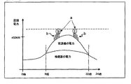
- FIG. It is a figure which shows transition of store electric power when EV charge electric power of Example 1 generate
- FIG. It is a figure which shows an example of the measurement data registered into a database from the measurement part of Example 1,2. It is a figure which shows an example of the table produced
- FIG. It is a timing chart which shows an example of the electric power control of a storage battery.
- 3 is a timing chart illustrating an example of heat storage operation control of the heat storage type air conditioning system according to the first embodiment. It is a figure which shows an example of the table which described the correspondence of the EV charging electric power predicted value of Example 1, and the number of air-conditioning systems which perform heat storage driving
- FIG. 15 is a flowchart for explaining in more detail the schedule determination process in step S30 of the flowchart of FIG. 14 of the first embodiment and the second embodiment. It is a flowchart for demonstrating in detail the storage battery control in step S60 of the flowchart of FIG. 14 of Example 1 and Example 2.
- FIG. 15 is a flowchart for explaining in more detail the schedule determination process in step S30 of the flowchart of FIG. 14 of the first embodiment and the second embodiment.
- FIG. 7 is a timing chart illustrating an example of heat storage operation control of the heat storage type showcase system according to the second embodiment. It is a figure which shows an example of the table which described the correspondence of the EV charging electric power predicted value of Example 2, and the number of showcase system
- FIG. 10 is a timing chart illustrating an example of the number control of the heat storage type showcase system according to the second embodiment. It is a figure which shows an example of the table which described the correspondence of the EV charging electric power predicted value of Example 2, and the supercooling degree of the showcase system
- 6 is a timing chart illustrating an example of supercooling degree control of the heat storage type showcase system according to the second embodiment. It is a figure which shows transition of store electric power when EV charge electric power which should be compared with FIG. 18 of Example 2 generate
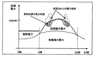
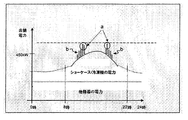
- FIG. 1 shows changes in store power when EV charging power is generated. This change in store power is in the summer season.
- the bar-shaped notation stacked on the curve indicating the power of the air conditioner indicates the EV charging power.
- the peak power of the air conditioner is about 200 kW.
- the EV charging power has a gradual change and a rapid change. The gradual change is a deterministic and predictable change (see region b).
- the sudden change is a change that is sudden and difficult to predict (see box a).
- EV charging power demand is classified into two categories.
- the former is the power demand that can be predicted to some extent and is determined to some extent depending on the day of the week and the time zone (hereinafter referred to as EV power 1 as appropriate).
- the EV power 1 is basically dealt with by reducing the air conditioning power by the regenerative air conditioning system.
- the latter is a demand for charging power that is difficult to predict power and occurs probabilistically and suddenly (hereinafter referred to as EV power 2 as appropriate).
- the EV power 2 is basically handled by the electric power stored in the storage battery. This is because it is difficult to meet the demand for electric power with a fast rate of change by reducing the air-conditioning power by the regenerative air-conditioning system, which requires a certain amount of time before the effect appears.
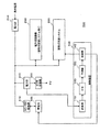
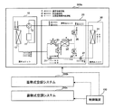
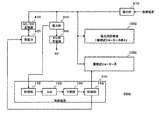
- FIG. 2 is a block diagram showing the configuration of the power control system 500 according to the embodiment of the present invention.
- the power control system 500 controls power to be supplied to equipment inside and outside the facility.
- the power control system 500 includes a control device 100, a regenerative air conditioning system 200, a power consuming device 250 (for example, lighting, a showcase, a refrigerator, etc., excluding the regenerative air conditioning system 200), and an EV charger 300. , A power meter 310, a storage battery 400, an AC / DC converter 410, and a power meter 510.
- Power meter 510 measures received power from a commercial power supply (AC power supply) and serves as basic data for charging by a power company (not shown).
- the wattmeter 310 measures the amount of power charged to the EV from the charger 300 and outputs it to the control device 100 (more precisely, a measurement unit 110 described later).
- the AC / DC converter 410 converts AC power supplied from a commercial power source into DC power and supplies it to the storage battery 400. Moreover, the DC power supplied from the storage battery 400 is converted into AC power and supplied to the facility power system.
- the storage battery 400 As the storage battery 400, a lithium ion battery, a nickel metal hydride battery, a lead battery, or the like can be used. In particular, lithium ion batteries are attracting attention because of their light weight, high capacity, and high output.
- the storage battery 400 can supply power to all facilities (in this embodiment, the charger 300, the heat storage type air conditioning system 200, and the power consuming device 250) that are installed in the facility and require power supply.
- the control device 100 includes a measurement unit 110, a database 120, a prediction unit 130, and a control unit 140. These configurations can be realized by an arbitrary processor, memory, or other LSI in terms of hardware, and can be realized by a program loaded in the memory in terms of software, but here by their cooperation. Draw functional blocks. Therefore, those skilled in the art will understand that these functional blocks can be realized in various forms by hardware only, software only, or a combination thereof.
- the measurement unit 110 acquires the EV charging power amount measured by the wattmeter 310 and registers it in the database 120 as measurement data.
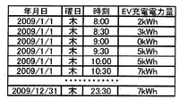
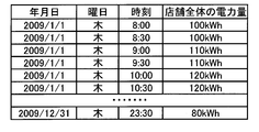
- FIG. 3 is a diagram illustrating an example of measurement data registered in the database 120 from the measurement unit 110.
- the EV charging electric energy measured by the wattmeter 310 is registered for each year, month, day, and time.
- the database 120 preferably holds at least measurement data for the past several months to one year.
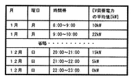
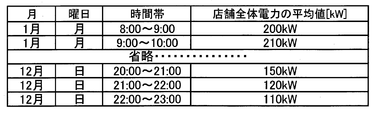
- FIG. 4 is a diagram showing an example of a table generated based on the measurement data shown in FIG.
- a database management unit (not shown) classifies past measurement data into months, days of the week, and time zones, and then calculates an average value of EV charging power. Then, the average value of the EV demand power is stored in a table format using the month, day of the week, and time zone as search keys.
- the table shown in FIG. 4 stores the average value for each hour from Monday to Sunday in the store's business hours.
- the prediction unit 130 uses this table as basic data of a prediction model of EV power 1.
- the air conditioner power is assumed to be a large store, and 10 heat storage air conditioning systems are installed in the store. Assume that there is air conditioning power consumption of about 200 kW at the peak of summer.
- air conditioning power consumption of about 200 kW occurs at large stores at the peak of summer power, and if 10 EVs are charged simultaneously, the charging power consumption of the EV charger is about 50 kW.
- this trial calculation is an example, and the present specification is not limited to this trial calculation.
- the prediction unit 130 refers to the database 120 to predict the transition of the charging power to the EV.
- the prediction unit 130 acquires the EV charging power demand that should be used as a predicted value by using the day, month, day of the week, and time zone to be predicted.
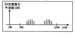
- FIG. 5 is a diagram illustrating an example of an EV charging power prediction value.
- the control unit 140 controls the heat storage and heat release of the heat storage type air conditioning system 200 based on the prediction result by the prediction unit 130.
- the control unit 140 controls to use the power stored in the storage battery 400 when the charging power to the EV exceeds the predicted value by the prediction unit 130. More specifically, the measured value of the charging power to the EV is compared with the predicted value of the charging power to the EV. If the measured value is larger than the predicted value, or the difference between the two exceeds a predetermined threshold value. In such a case, control is performed so that the power stored in the storage battery 400 is used.
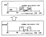
- control unit 140 responds to the time zone during which the electric power charged to the EV changes within the predicted range by the heat storage use operation of the heat storage type air conditioning system 200, and the time when the electric power is changing beyond the predicted range.
- the band corresponds to the power stored in the storage battery 400.
- control unit 140 may change the number of air conditioning systems that are operated using the heat storage according to the predicted value of the electric power charged to the EV, or the heat storage type air conditioning system 200.
- the degree of supercooling of the refrigerant circulating in the air conditioning system may be changed.
- FIG. 6 is a diagram illustrating a configuration example of the heat storage type air conditioning system 200.
- an example of a refrigerant circuit diagram relating to an individual distributed heat storage air conditioning system is shown.
- the example (three systems in FIG. 6) in which the heat storage type air conditioning system 200 exists n (n is a natural number) systems is shown.
- n is a natural number
- an example in which a plurality of air conditioners are arranged by arranging a plurality of heat storage air conditioning systems is shown, but a plurality of air conditioners are arranged by sharing one heat storage unit. It may be a configuration.
- the heat storage air conditioning system 200 a includes an outdoor unit 10, a heat storage unit 20, and an indoor unit 30.
- the outdoor unit 10 includes a compressor 11, a four-way valve 12, and an outdoor exchanger 13.
- the heat storage unit 20 includes an expansion valve 21, an on-off valve 22, an on-off valve 23, a heat storage tank 24, an on-off valve 25, an on-off valve 26 and an expansion valve 27.
- the indoor unit 30 includes an indoor heat exchanger 31.
- the heat storage tank 24 includes a heat storage heat exchanger (not shown). In this refrigerant circuit, three types of cooling operations (that is, normal cooling operation, ice heat storage operation, and ice heat storage operation) are possible.
- One air conditioning system is configured by connecting an indoor heat exchanger, an outdoor heat exchanger, and a compressor by a refrigerant pipe.
- the on-off valve 22, on-off valve 23, on-off valve 25, and on-off valve 26 are all closed, and the heat storage tank 24 is not used. That is, a refrigerant circulation path in which the compressor 11, the four-way valve 12, the outdoor exchanger 13, the expansion valve 21, the expansion valve 27, and the indoor heat exchanger 31 are connected in an annular shape is formed, and the refrigerant circulates through the path. The heat is exchanged by the indoor heat exchanger 31, and the indoor temperature can be lowered. In normal cooling operation, operation is performed by electric power supplied from a commercial power source.
- the on-off valve 23 and the on-off valve 25 are closed, and the on-off valve 22 and the on-off valve 26 are opened. That is, a refrigerant circulation path is formed in which the compressor 11, the four-way valve 12, the outdoor exchanger 13, the expansion valve 21, the on-off valve 22, the heat storage tank 24, and the on-off valve 26 are connected in an annular shape, and the refrigerant circulates through the path. As a result, ice is made in the heat storage tank 24.
- the on-off valve 22 and the on-off valve 26 are closed, and the on-off valve 23 and the on-off valve 25 are opened. That is, the compressor 11, the four-way valve 12, the outdoor exchanger 13, the expansion valve 21, the expansion valve 27, the on-off valve 23, the heat storage tank 24, the on-off valve 25, the expansion valve 27, and the indoor heat exchanger 31 are connected in an annular shape. A refrigerant circulation path is formed, and the refrigerant circulates through the path, whereby heat is exchanged by the indoor heat exchanger 31 and the indoor temperature can be lowered. In the ice storage cooling operation, the operation is performed by the energy stored in the heat storage tank 24.
- the heat storage type air conditioning system 200b and the heat storage type air conditioning system 200c have the same configuration. As described above, there are two types of capacity control methods for the regenerative air conditioning system 200 (that is, methods for adjusting the amount of air conditioning power reduction). Number control and supercooling degree control.
- the control unit 140 controls the number of air conditioning systems to be operated using heat storage according to the air conditioning power to be reduced.
- One air conditioning system is configured by connecting an indoor heat exchanger, an outdoor heat exchanger, and a compressor by a refrigerant pipe. There are multiple air conditioning systems in the facility.
- the control unit 140 controls the number of air conditioning systems that are operated using heat storage according to the air conditioning power to be reduced.
- each of the heat storage type air conditioning systems 200a to 200c is designated to perform normal cooling operation, ice heat storage cooling operation, or not.
- the control unit 140 controls the supercooling degree of the air conditioning system according to the air conditioning power to be reduced.
- the supercooling degree is set high.
- the degree of supercooling is set low.
- control unit 140 controls the ratio between the refrigerant flow rate that flows through the heat storage heat exchanger in the heat storage tank 24 and the refrigerant flow rate that bypasses the heat storage tank 24 by the opening / closing valve 25 and the opening / closing valve 23.
- the supercooling degree of the refrigerant is controlled.
- the control unit 140 outputs a control signal for designating an opening / closing rate to the opening / closing valve 25 and the opening / closing valve 23 of each heat storage type air conditioning system 200a-c.
- the refrigerant circuit shown in FIG. 6 is an example, and a refrigerant circuit of a type including cold water or brine for heat exchange between a refrigerator dedicated to cold heat storage in a heat storage tank and a refrigerant in an air conditioning system may be used. Good. In that case, the flow rate of cold water or brine that exchanges heat with the refrigerant in the air conditioning system can be controlled to control the degree of supercooling of the air conditioning system that performs the heat storage operation and the number of air conditioning systems that perform the heat storage operation. Moreover, in the example mentioned above, although one heat storage tank exists for every one air conditioning system, you may use the refrigerant circuit of the structure which shares a heat storage tank in a some air conditioning system.
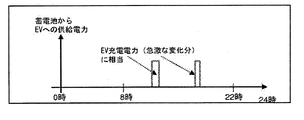
- FIG. 7 is a timing chart showing an example of power control of the storage battery 400.
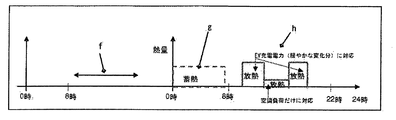
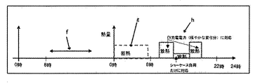
- FIG. 8 is a timing chart showing an example of heat storage operation control of the heat storage type air conditioning system 200.
- the prediction unit 130 predicts the heat storage amount to the heat storage tank 24 the day before the control date, and the control unit 140 determines the schedule of the heat storage use operation on the control day (FIG. 8).
- the control date refers to a target date on which the combined control of the heat storage utilization operation control and the storage battery control is performed.
- the control unit 140 stores the heat storage amount predicted by the prediction unit 130 in the heat storage tank 24 during the night time zone on the control day (see g in FIG. 8).
- the control part 140 performs heat storage utilization operation control on the control date (see h in FIG. 8).
- the control part 140 performs the power control of the storage battery 400 on the control date (see FIG. 7).
- the control unit 140 deals with the EV power 1 by the heat storage use operation control, and deals with the EV power 2 by the power control of the storage battery 400.
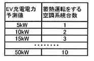
- FIG. 9 is a diagram illustrating an example of a table describing a correspondence relationship between an EV charge power prediction value and the number of air conditioning systems that perform a heat storage operation.
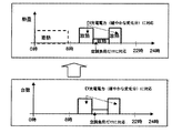
- FIG. 10 is a timing chart showing an example of the number control of the regenerative air conditioning system 200.
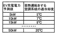
- FIG. 11 is a diagram illustrating an example of a table describing a correspondence relationship between the EV charging power predicted value and the degree of supercooling of the air conditioning system performing the heat storage operation.
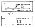
- FIG. 12 is a timing chart showing an example of supercooling degree control of the regenerative air conditioning system 200.
- a large degree of supercooling indicates that the amount of heat released from the heat storage tank 24 is large, and the amount of air-conditioning power reduced by the heat storage utilization operation is large. Therefore, by increasing the degree of supercooling, not only the air conditioning load but also the EV power 1 can be handled.
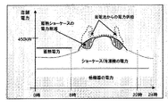
- FIG. 13 shows the transition of store power when EV charging power is generated, which should be compared with FIG.
- the area surrounded by the curved dotted line indicates the power reduced by the heat storage operation control.
- the rod-shaped dotted line area indicates the power covered by the power supply from the storage battery 400. It shows that the peak power was successfully suppressed within 450 kW by applying the control method according to the present embodiment. On the other hand, in FIG. 1, a time zone exceeding 450 kW occurs.
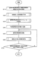
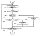
- FIG. 14 is a flowchart for explaining overall control of heat storage type air conditioning system 200 and storage battery 400 by control device 100 according to the embodiment of the present invention. This flowchart shows one cycle of the control.
- control unit 140 determines the date and time (more specifically, the control date and its start time and end time) when the combined control of the heat storage use operation control and the storage battery control is performed (S10).
- the prediction unit 130 predicts the amount of heat stored in the heat storage tank 24 before the control start date and time (for example, 24 hours before the control start date and time) (S20).
- the heat storage amount related to the air conditioning load is considered.
- An existing general technique is used for a method of predicting the amount of heat storage for reducing air-conditioning power corresponding to the air-conditioning load (for example, ventilation load, solar heat load, etc.).
- the amount of heat storage related to EV power 1 will be considered.
- EV charging power demand a charging power that is predictable to a certain extent and is gradual is predicted. This charging power demand can be predicted to some extent depending on the day of the week and the time zone. Then, a heat storage amount corresponding to the predicted charging power is calculated.
- the heat storage amount corresponds to the reduced power of the air conditioner.
- a charging power prediction model based on the table shown in FIG. 4 described above can be used. And let the total heat storage amount be the sum of the heat storage amount related to the air conditioning load and the heat storage amount related to the EV power 1.
- the control unit 140 predicts the schedule of the heat storage utilization operation control before the control start date and time (for example, 24 hours before the control start date and time) (S30).
- the schedule defines how much air conditioning power is reduced at what time.
- the control unit 140 uses the above-described charging power prediction result of the EV power 1 (more strictly, a change in the charging power of the EV power 1 for each time zone) to reduce the air conditioning corresponding to the charging power of the EV power 1.
- a heat storage use operation pattern on the control day is determined so that electric power can be obtained. Examples of the heat storage utilization operation pattern include an operation schedule for unit control or an operation schedule for supercooling degree control.
- the control unit 140 performs control so that the heat storage amount predicted in the night time zone before the start of control is stored in the heat storage tank 24 (S40).
- the regenerative air conditioning system 200 is operated so that the predicted heat storage amount is stored in the night time zone of the previous day.
- the refrigerant circuit shown in FIG. 6 there is a heat storage tank for each air conditioning system, so it is necessary to store cold in the heat storage tank 24 of the air conditioning system that operates using heat storage, and the heat storage tank of the corresponding air conditioning system. 24 stores cold energy.
- the number control is used, the cold energy is stored in the heat storage tank 24 of the air conditioning system that performs the number control.
- supercooling degree control cold heat is stored in the heat storage tank 24 of the air conditioning system that performs supercooling degree control.
- the control unit 140 performs the number control or the supercooling degree control according to the heat storage utilization operation pattern on the control day (S50). More specifically, the control unit 140 transmits necessary command information to the heat storage unit 20 for each time according to the operation time chart information held in advance.
- the number of air-conditioning systems that perform heat storage operation (that is, increase or decrease in the number of units) is controlled according to the number of units that perform heat storage operation (that is, the number of air-conditioning systems that dissipate cold stored in the heat storage tank).
- the control unit 140 transmits a control signal for starting the heat storage operation to the system performing the heat storage operation according to the scheduling. According to this control signal, the corresponding air conditioning system performs cooling operation using ice heat storage.
- the stored cold heat is radiated according to the scheduling of the supercooling degree of the air conditioning system operated using ice heat storage.
- the control unit 140 transmits a control signal of a predetermined supercooling degree for each air conditioning system that performs the heat storage operation according to the scheduling.
- the corresponding air conditioning system adjusts the flow rate of the refrigerant flowing in the heat storage tank 24 by the open / close valves 25 and 23 in order to adjust the temperature of the degree of supercooling.
- the degree of supercooling is adjusted by adjusting the ratio of the refrigerant flow rate flowing through the heat storage heat exchanger of the heat storage tank 24 and the refrigerant flow rate bypassing the heat storage heat exchanger by the on-off valves 25 and 23.
- the control unit 140 performs power control of the storage battery 400 on the control day (S60).
- the EV charging power by the charger 300 is measured, the measured EV charging power is compared with the predicted value of the EV power 1 at the corresponding time, and if the measured power exceeds the predicted power, the power is supplied from the storage battery 400. To do.
- the control unit 140 repeatedly executes the control in step S50 and step S60 until the end time of the combined control of the heat storage use operation control and the storage battery control is reached (N in S70). When the end time is reached (Y in S70), the combined control on the control date is ended.
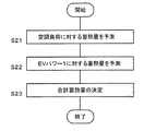
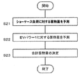
- FIG. 15 is a flowchart for explaining the prediction process in step S20 in the flowchart of FIG. 14 in more detail.
- the prediction unit 130 predicts the heat storage amount with respect to the air conditioning load (S21). For example, the air conditioning load on the current day is predicted using the outside air temperature, the average value of the air conditioning load for the past several days, or the air conditioning load on the previous day. And based on the prediction air-conditioning load of the day, the heat storage amount required for air-conditioning power reduction is determined.
- the prediction unit 130 predicts the heat storage amount for the EV power 1 (S22). For example, with respect to the EV charging power prediction model based on the table shown in FIG. 4, the month, day of the week and time zone of the control day are input, and the predicted value of the EV charging power according to the time zone of the day is acquired. . And the heat storage amount (namely, heat storage amount required for a heat storage utilization driving
- the relational expression of the air conditioning reduction power amount [kWh] with respect to the heat storage amount [kJ] is defined as ⁇ , and the control date calculated from the predicted value of EV charging power EV charge power amount) / ⁇ is calculated to obtain the heat storage amount.
- the prediction unit 130 adds the heat storage amount related to the air conditioning load and the heat storage amount related to the EV power 1 to determine the total heat storage amount (S23).
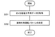
- FIG. 16 is a flowchart for explaining the schedule determination process in step S30 of the flowchart of FIG. 14 in more detail.
- the control unit 140 acquires EV charging power prediction data (more strictly, transition of charging power for each time zone) predicted in step S20 of FIG. 14 (S31).
- control unit 140 uses the EV charge power prediction data to determine the heat storage use operation pattern of the day so that the air conditioning reduction power corresponding to the EV charge power can be covered by improving the efficiency of the air conditioner by the heat storage use operation. (S32).
- the control unit 140 controls the number of air conditioning systems that are operated using heat storage according to the EV charging power demand. For example, the EV charging power demand is classified into a plurality of stages, and the number of heat storage operation is determined according to the size. Specifically, when the EV charge power demand is large, the number of air conditioning systems that are operated using heat storage is increased, and when the EV charge power demand is small, the number of air conditioning systems that are operated using heat storage is decreased. For example, as shown in FIG.
- a table in which the magnitude of the EV charging power demand is associated with the number of air conditioning systems to be operated using heat storage is created, and according to the EV predicted charging power (for example, see FIG. 5),
- the scheduling of the number of air conditioning systems that operate using heat storage is determined as shown in FIG.
- the scheduling indicates how many units are operated using the heat storage in which time zone.
- the control unit 140 determines the degree of supercooling of the air conditioning system that operates using heat storage according to the EV charging power demand. Specifically, when the EV charging power demand is large, the degree of supercooling is increased, and when the EV charging power demand is small, the degree of supercooling is decreased.
- an air conditioning system that creates a table in which the magnitude of the EV predicted charging power and the degree of supercooling are associated with each other and performs the heat storage operation according to the EV predicted charging power (for example, see FIG. 5).
- the scheduling of the degree of supercooling is determined as shown in FIG. The schedule indicates how much supercooling is set in which time zone.
- the degree of supercooling may be specified only for a specific air conditioning system or all air conditioning systems.
- the above information (that is, scheduling information related to unit control or supercooling degree control) is stored in advance in a memory (not shown) of the control device 100.
- FIG. 17 is a flowchart for explaining the storage battery control in step S60 of the flowchart of FIG. 14 in more detail.
- the wattmeter 310 measures the EV charging power and outputs it as the EV charging power measurement value to the measuring unit 110 (S61).
- the prediction unit 130 calculates a current EV charging power prediction value from the EV charging power prediction model (S62). As described above, the current EV charging power prediction value can be acquired by designating the month, day of the week, and time zone.
- the control unit 140 compares the EV charging power predicted value of the corresponding date and time with the EV charging power measurement value (S63). When the measured value exceeds the predicted value (Y in S63), a discharge command to the power system is output to the storage battery 400 (S64). Thereby, electric power is supplied from the storage battery 400 to the electric power system.
- the control unit 140 determines whether or not the storage battery 40 is discharged to the power system (S65). When the battery is discharged (Y in S65), a discharge stop command to the power system is output to the storage battery 400 (S66). Thereby, the discharge from the storage battery 400 to the power system stops.
- Step S65 When not discharging (N in S65), the control unit 140 proceeds to Step S61 and repeatedly executes the storage battery control until the end time of the storage battery control is reached (N in S67). When the end time is reached (Y in S67), the storage battery control is ended.
- a gradual charging power change that can be predicted to some extent can be handled by a thermal storage air conditioning system, and sudden charging that is difficult to predict
- the peak power of the store accompanying the increase in EV charging power demand can be reduced, and the power of the store can be leveled.
- the electricity bill for the entire store can be reduced.
- the table shown in FIG. 4 uses past measurement data as search keys for month, day of the week, and time, but a database management unit (not shown) acquires weather conditions (for example, outside temperature, humidity) from an external server and searches them. May be added to the key. In this case, the EV charging power demand can be predicted with higher accuracy.
- weather conditions for example, outside temperature, humidity
- FIG. 18 shows changes in store power when EV charging power is generated. This change in store power is in the summer season.
- the bar-shaped notation stacked on the curve indicating the power of the showcase indicates the EV charging power.
- the peak power of the showcase / refrigerator is about 200 kW.
- the EV charging power has a gradual change and a rapid change. The gradual change is a deterministic and predictable change (see region b).
- the sudden change is a change that is sudden and difficult to predict (see box a).
- EV charging power demand is classified into two categories.
- the former is the power demand that can be predicted to some extent and is determined to some extent depending on the day of the week and the time zone (hereinafter referred to as EV power 1 as appropriate).
- the EV power 1 is basically dealt with by reducing the power of the showcase / refrigerator by the regenerative showcase system.
- the latter is a demand for charging power that is difficult to predict power and occurs probabilistically and suddenly (hereinafter referred to as EV power 2 as appropriate).
- the EV power 2 is basically handled by the electric power stored in the storage battery. This is because it is difficult to respond to power demand with a fast rate of change by reducing the power of the showcase / refrigerator by the heat storage type showcase system, which requires a certain amount of time before the effect appears.
- FIG. 19 is a block diagram showing a configuration of a power control system 5000 according to the embodiment of the present invention.
- the power control system 5000 controls power to be supplied to equipment inside and outside the facility.
- the power control system 5000 includes a control device 100, a heat storage type showcase system 1200, a power consuming device 1250 (eg, lighting, air conditioning, etc., excluding the heat storage type showcase system 1200), an EV charger 300, power A total 310, a storage battery 400, an AC / DC converter 410, and a power meter 510 are provided.
- Power meter 510 measures received power from a commercial power supply (AC power supply) and serves as basic data for charging by a power company (not shown).
- the wattmeter 310 measures the amount of power charged to the EV from the charger 300 and outputs it to the control device 100 (more precisely, a measurement unit 110 described later).
- the AC / DC converter 410 converts AC power supplied from a commercial power source into DC power and supplies it to the storage battery 400. Moreover, the DC power supplied from the storage battery 400 is converted into AC power and supplied to the facility power system.
- the storage battery 400 As the storage battery 400, a lithium ion battery, a nickel metal hydride battery, a lead battery, or the like can be used. In particular, lithium ion batteries are attracting attention because of their light weight, high capacity, and high output.
- the storage battery 400 can supply power to all facilities (in this embodiment, the charger 300, the heat storage type showcase system 1200, and the power consuming device 1250) that are installed in the facility and require power supply.
- the control device 100 includes a measurement unit 110, a database 120, a prediction unit 130, and a control unit 140. These configurations can be realized by an arbitrary processor, memory, or other LSI in terms of hardware, and can be realized by a program loaded in the memory in terms of software, but here by their cooperation. Draw functional blocks. Therefore, those skilled in the art will understand that these functional blocks can be realized in various forms by hardware only, software only, or a combination thereof.
- the measurement unit 110 acquires the EV charging power amount measured by the wattmeter 310 and registers it in the database 120 as measurement data.
- FIG. 3 is a diagram illustrating an example of measurement data registered in the database 120 from the measurement unit 110.
- the EV charging electric energy measured by the wattmeter 310 is registered for each year, month, day, and time.
- the database 120 preferably holds at least measurement data for the past several months to one year.
- FIG. 4 is a diagram showing an example of a table generated based on the measurement data shown in FIG.
- a database management unit (not shown) classifies past measurement data into months, days of the week, and time zones, and then calculates an average value of EV charging power. Then, the average value of the EV demand power is stored in a table format using the month, day of the week, and time zone as search keys.
- the table shown in FIG. 4 stores the average value for each hour from Monday to Sunday in the store's business hours.
- the prediction unit 130 uses this table as basic data of a prediction model of EV power 1.
- the power consumption of a showcase / refrigerator of about 200 kW occurs at the peak of summer power, and if 10 EVs are charged simultaneously, the charging power consumption of the EV charger is about 50 kW. .
- this trial calculation is an example, and the present specification is not limited to this trial calculation.
- the prediction unit 130 refers to the database 120 to predict the transition of the charging power to the EV.
- the prediction unit 130 acquires the EV charging power demand that should be used as a predicted value by using the day, month, day of the week, and time zone to be predicted.
- FIG. 5 is a diagram illustrating an example of an EV charging power prediction value.
- the control unit 140 controls heat storage and heat dissipation of the heat storage type showcase system 1200 based on the prediction result by the prediction unit 130.
- the control unit 140 controls to use the power stored in the storage battery 400 when the charging power to the EV exceeds the predicted value by the prediction unit 130. More specifically, the measured value of the charging power to the EV is compared with the predicted value of the charging power to the EV. If the measured value is larger than the predicted value, or the difference between the two exceeds a predetermined threshold value. In such a case, control is performed so that the power stored in the storage battery 400 is used.
- control unit 140 responds by the heat storage use operation of the heat storage type showcase system 1200 during the time zone in which the charging power to the EV changes within the prediction range, and changes beyond the prediction range.
- the time zone corresponds to the power stored in the storage battery 400.
- control unit 140 may change the number of showcase systems operated using the heat storage according to the predicted value of the electric power charged to the EV.
- the degree of supercooling of the refrigerant circulating in the showcase system in the case system 1200 may be changed.
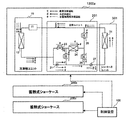
- FIG. 20 is a diagram illustrating a configuration example of a heat storage type showcase system 1200.
- an example of a refrigerant circuit diagram relating to an individual distributed heat storage type showcase system is shown.
- the example (three systems in FIG. 20) in which the heat storage type showcase system 1200 exists (n is a natural number) systems is shown.
- a plurality of showcase systems are arranged by arranging a plurality of heat storage type showcase systems, but a plurality of showcases are arranged by sharing one heat storage unit. It may be configured.
- the heat storage type showcase system 1200 a includes a refrigerator unit 10, a heat storage unit 201, and a showcase unit 301.
- the refrigerator unit 10 includes a compressor 11 and an outdoor exchanger 13.
- the heat storage unit 201 includes an expansion valve 21, an on-off valve 22, an on-off valve 23, a heat storage tank 24, an on-off valve 25, an on-off valve 26 and an expansion valve 27.
- the showcase unit 301 includes the indoor heat exchanger 31.
- the heat storage tank 24 includes a heat storage heat exchanger (not shown). In this refrigerant circuit, three types of cooling operation (that is, normal cooling operation, ice heat storage operation, and ice heat storage utilization operation) are possible.
- One showcase system is configured by connecting an indoor heat exchanger, an outdoor heat exchanger, and a compressor by a refrigerant pipe.
- the on-off valve 22, the on-off valve 23, the on-off valve 25, and the on-off valve 26 are all closed, and the heat storage tank 24 is not used. That is, a refrigerant circulation path in which the compressor 11, the outdoor exchanger 13, the expansion valve 21, the expansion valve 27, and the indoor heat exchanger 31 are connected in an annular shape is formed, and the refrigerant circulates through the path, thereby exchanging indoor heat. Heat is exchanged by the vessel 31, and the temperature in the showcase cabinet can be lowered. In the normal cooling operation, the operation is performed by electric power supplied from a commercial power source.
- the on-off valve 23 and the on-off valve 25 are closed, and the on-off valve 22 and the on-off valve 26 are opened. That is, a refrigerant circulation path in which the compressor 11, the outdoor exchanger 13, the expansion valve 21, the on-off valve 22, the heat storage tank 24, and the on-off valve 26 are connected in an annular shape is formed, and the refrigerant circulates in the path, thereby Ice is made in the tank 24.
- the on-off valve 22 and the on-off valve 26 are closed, and the on-off valve 23 and the on-off valve 25 are opened. That is, a refrigerant circulation path in which the compressor 11, the outdoor exchanger 13, the expansion valve 21, the expansion valve 27, the on-off valve 23, the heat storage tank 24, the on-off valve 25, the expansion valve 27, and the indoor heat exchanger 31 are connected in an annular shape.
- the refrigerant is circulated through the path, heat is exchanged by the indoor heat exchanger 31, and the temperature in the showcase cabinet can be lowered.
- the operation is performed by the energy stored in the heat storage tank 24.
- the heat storage type showcase system 1200b and the heat storage type showcase system 1200c have the same configuration. As described above, there are two types of capacity control methods for the heat storage type showcase system 1200 (that is, methods for adjusting the amount of power reduction in the showcase / refrigerator). Number control and supercooling degree control.
- the control unit 140 controls the number of showcase systems to be operated using heat storage according to the power of the showcase / refrigerator to be reduced.
- One showcase system is configured by connecting an indoor heat exchanger, an outdoor heat exchanger, and a compressor by a refrigerant pipe.
- the control unit 140 controls the number of showcase systems to be operated using heat storage according to the power of the showcase / refrigerator to be reduced.
- each of the heat storage type showcase systems 1200a to 1200c is designated to perform normal cooling operation, ice heat storage cooling operation, or no operation.
- the control unit 140 controls the supercooling degree of the showcase system according to the power of the showcase / refrigerator to be reduced. If you want to increase the power consumption of the showcase / refrigerator (ie increase the efficiency increase rate), set the supercooling degree high. On the other hand, when it is desired to reduce the power consumption of the showcase / refrigerator (that is, to reduce the increase rate of the showcase efficiency), the supercooling degree is set low.
- control unit 140 controls the ratio between the refrigerant flow rate that flows through the heat storage heat exchanger in the heat storage tank 24 and the refrigerant flow rate that bypasses the heat storage tank 24 by the opening / closing valve 25 and the opening / closing valve 23.
- the supercooling degree of the refrigerant is controlled.
- the control unit 140 outputs a control signal for designating an opening / closing rate to the opening / closing valve 25 and the opening / closing valve 23 of each heat storage type showcase system 1200a-c.
- the refrigerant circuit shown in FIG. 20 is only an example, and a refrigerant circuit of a type including cold water or brine for heat exchange with a refrigerator dedicated to cold heat storage in a heat storage tank and a refrigerant in a showcase system is used. Also good. In that case, by controlling the flow rate of cold water or brine that exchanges heat with the refrigerant in the showcase system, control the degree of subcooling of the showcase system that performs heat storage use operation and the number of showcase systems that perform heat storage use operation You can also. Moreover, in the example mentioned above, although one heat storage tank exists for every showcase system
- FIG. 21 is a timing chart showing an example of power control of the storage battery 400.
- FIG. 22 is a timing chart showing an example of heat storage operation control of the heat storage type showcase system 1200.
- the prediction unit 130 predicts the heat storage amount to the heat storage tank 24 on the day before the control date, and the control unit 140 determines the schedule of the heat storage use operation on the control day (FIG. 22 f).
- the control date refers to a target date on which the combined control of the heat storage utilization operation control and the storage battery control is performed.
- the control unit 140 stores the heat storage amount predicted by the prediction unit 130 in the heat storage tank 24 during the night time zone on the control day (see g in FIG. 22).
- the control unit 140 executes the heat storage utilization operation control on the control date (see h in FIG. 22).
- control part 140 performs the electric power control of the storage battery 400 on a control day (refer FIG. 21).
- the control unit 140 deals with the EV power 1 by the heat storage use operation control, and deals with the EV power 2 by the power control of the storage battery 400.
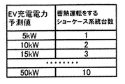
- FIG. 23 is a diagram illustrating an example of a table describing a correspondence relationship between a predicted EV charge power value and the number of showcase systems performing heat storage operation.
- FIG. 24 is a timing chart showing an example of the number control of the heat storage type showcase system 1200.
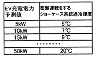
- FIG. 25 is a diagram illustrating an example of a table describing a correspondence relationship between a predicted EV charge power value and a degree of supercooling of a showcase system performing a heat storage operation.
- FIG. 26 is a timing chart showing an example of supercooling degree control of the heat storage type showcase system 1200.
- the fact that the degree of supercooling is large indicates that the amount of heat released from the heat storage tank 24 is large, and the amount of reduction in showcase power by the heat storage utilization operation is large. Therefore, by increasing the degree of supercooling, not only showcase load but also EV power 1 can be handled.
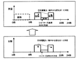
- FIG. 27 shows the transition of store power when EV charging power is generated, which should be compared with FIG.
- the area surrounded by the curved dotted line indicates the power reduced by the heat storage operation control.
- the rod-shaped dotted line area indicates the power covered by the power supply from the storage battery 400. It shows that the peak power was successfully suppressed within 450 kW by applying the control method according to the present embodiment. In contrast, in FIG. 18, a time zone exceeding 450 kW occurs.
- FIG. 14 is a flowchart for explaining overall control of heat storage type showcase system 1200 and storage battery 400 by control device 100 according to the embodiment of the present invention. This flowchart shows one cycle of the control.
- control unit 140 determines the date and time (more specifically, the control date and its start time and end time) when the combined control of the heat storage use operation control and the storage battery control is performed (S10).
- the prediction unit 130 predicts the amount of heat stored in the heat storage tank 24 before the control start date and time (for example, 24 hours before the control start date and time) (S20).
- the amount of heat storage related to the showcase load is considered.
- the existing general technique is used for a method of predicting the amount of heat storage for reducing the power of the showcase / refrigerator corresponding to the showcase load (for example, outside air load).
- the amount of heat storage related to EV power 1 will be considered.
- EV charging power demand a charging power that is predictable to a certain extent and is gradual is predicted. This charging power demand can be predicted to some extent depending on the day of the week and the time zone. Then, a heat storage amount corresponding to the predicted charging power is calculated.
- the heat storage amount corresponds to the reduced power consumption of the showcase.
- a charging power prediction model based on the table shown in FIG. 4 described above can be used. And let the total heat storage amount be the sum of the heat storage amount related to the showcase load and the heat storage amount related to the EV power 1.
- the control unit 140 predicts the schedule of the heat storage utilization operation control before the control start date and time (for example, 24 hours before the control start date and time) (S30).
- the schedule defines how much showcase power is reduced at what time.
- the control unit 140 uses the above-described charging power prediction result of EV power 1 (more strictly, a change in charging power of EV power 1 for each time zone), and a showcase corresponding to the charging power of EV power 1 / Determine the heat storage use operation pattern on the control day so that reduced power consumption of the refrigerator can be obtained.
- Examples of the heat storage utilization operation pattern include an operation schedule for unit control or an operation schedule for supercooling degree control.
- the control unit 140 performs control so that the heat storage amount predicted in the night time zone before the start of control is stored in the heat storage tank 24 (S40).
- the heat storage type showcase system 1200 is operated so as to store the predicted heat storage amount in the night time zone of the previous day.
- the refrigerant circuit shown in FIG. 20 there is a heat storage tank for each showcase system. Therefore, it is necessary to store cold heat in the heat storage tank 24 of the showcase system that operates using heat storage. The cold energy is stored in the heat storage tank 24.
- the number control cold heat is stored in the heat storage tank 24 of the showcase system that performs the number control.
- supercooling degree control cold heat is stored in the heat storage tank 24 of the showcase system that performs supercooling degree control.
- the control unit 140 performs the number control or the supercooling degree control according to the heat storage utilization operation pattern on the control day (S50). More specifically, the control unit 140 transmits necessary command information to the heat storage unit 20 for each time according to the operation time chart information held in advance.
- the control unit 140 transmits a control signal for starting the heat storage operation to the system performing the heat storage operation according to the scheduling. According to this control signal, the corresponding showcase system performs a cooling operation using ice heat storage.
- the stored cold is radiated according to the scheduling of the supercooling degree of the showcase system operated using ice heat storage.
- the control unit 140 transmits a control signal of a predetermined degree of supercooling for each showcase system performing the heat storage operation according to the scheduling.
- the corresponding showcase system adjusts the flow rate of the refrigerant flowing in the heat storage tank 24 by the on-off valves 25 and 23 in order to adjust the temperature of the degree of supercooling.
- the degree of supercooling is adjusted by adjusting the ratio of the refrigerant flow rate flowing through the heat storage heat exchanger of the heat storage tank 24 and the refrigerant flow rate bypassing the heat storage heat exchanger by the on-off valves 25 and 23.
- the control unit 140 performs power control of the storage battery 400 on the control day (S60).
- the EV charging power by the charger 300 is measured, the measured EV charging power is compared with the predicted value of the EV power 1 at the corresponding time, and if the measured power exceeds the predicted power, the power is supplied from the storage battery 400. To do.
- the control unit 140 repeatedly executes the control in step S50 and step S60 until the end time of the combined control of the heat storage use operation control and the storage battery control is reached (N in S70). When the end time is reached (Y in S70), the combined control on the control date is ended.
- FIG. 28 is a flowchart for explaining in more detail the prediction process in step S20 of the flowchart of FIG.
- the prediction unit 130 predicts the heat storage amount with respect to the showcase load (S21).
- the showcase load of the day is predicted using the temperature and humidity in the store, the temperature and humidity of the outside air, the average value of the showcase load of the past few days, or the showcase load of the previous day. Then, based on the predicted showcase load of the day, the amount of heat storage required for showcase power reduction is determined.
- the prediction unit 130 predicts the heat storage amount for the EV power 1 (S22). For example, with respect to the EV charging power prediction model based on the table shown in FIG. 4, the month, day of the week and time zone of the control day are input, and the predicted value of the EV charging power according to the time zone of the day is acquired. . And the heat storage amount (namely, heat storage amount required for heat storage utilization driving
- the heat storage amount namely, heat storage amount required for heat storage utilization driving
- the relational expression of the showcase / refrigerator reduced power consumption [kWh] with respect to the heat storage amount [kJ] is defined as ⁇ based on the measurement data at the time of the past heat storage utilization operation and the like (calculated from the predicted value of EV charging power Calculated EV charge electric energy) / ⁇ on the control date to obtain the heat storage amount.
- the prediction unit 130 adds the heat storage amount related to the showcase load and the heat storage amount related to the EV power 1 to determine the total heat storage amount (S23).
- FIG. 16 is a flowchart for explaining the schedule determination process in step S30 of the flowchart of FIG. 14 in more detail.
- the control unit 140 acquires EV charging power prediction data (more strictly, transition of charging power for each time zone) predicted in step S20 of FIG. 14 (S31).
- control unit 140 uses the EV charging power prediction data to store the showcase / refrigerator reduced power corresponding to the EV charging power by improving the efficiency of the showcase through the heat storage use operation.
- a usage operation pattern is determined (S32).
- the control unit 140 controls the number of showcase systems that operate using heat storage according to the EV charging power demand.
- the EV charging power demand is classified into a plurality of stages, and the number of heat storage operation is determined according to the size. Specifically, when the EV charge power demand is large, the number of showcase systems that perform heat storage operation is increased, and when the EV charge power demand is small, the number of showcase systems that perform heat storage operation is decreased.
- FIG. 23 a table in which the magnitude of EV charging power demand is associated with the number of showcase systems that operate using heat storage is created, and the EV charging power (for example, refer to FIG. 5) is created.
- the scheduling of the number of showcase systems that operate using heat storage is determined as shown in FIG. The scheduling indicates how many units are operated using the heat storage in which time zone.
- the control unit 140 determines the degree of supercooling of the showcase system that performs the heat storage utilization operation according to the EV charging power demand. Specifically, when the EV charging power demand is large, the degree of supercooling is increased, and when the EV charging power demand is small, the degree of supercooling is decreased. For example, as shown in FIG. 25, a table in which the magnitude of the EV predicted charging power is associated with the degree of supercooling is generated, and the heat storage operation is performed according to the EV predicted charging power (for example, see FIG. 5).
- the scheduling of the supercooling degree of the system is determined as shown in FIG. The schedule indicates how much supercooling is set in which time zone. Note that the degree of supercooling may be specified only for a specific showcase system or all showcase systems.
- the above information (that is, scheduling information related to unit control or supercooling degree control) is stored in advance in a memory (not shown) of the control device 100.
- FIG. 17 is a flowchart for explaining the storage battery control in step S60 of the flowchart of FIG. 14 in more detail.
- the wattmeter 310 measures the EV charging power and outputs it as the EV charging power measurement value to the measuring unit 110 (S61).
- the prediction unit 130 calculates a current EV charging power prediction value from the EV charging power prediction model (S62). As described above, the current EV charging power prediction value can be acquired by designating the month, day of the week, and time zone.
- the control unit 140 compares the EV charging power predicted value of the corresponding date and time with the EV charging power measurement value (S63). When the measured value exceeds the predicted value (Y in S63), a discharge command to the power system is output to the storage battery 400 (S64). Thereby, electric power is supplied from the storage battery 400 to the electric power system.
- the control unit 140 determines whether or not the storage battery 40 is discharged to the power system (S65). When the battery is discharged (Y in S65), a discharge stop command to the power system is output to the storage battery 400 (S66). Thereby, the discharge from the storage battery 400 to the power system stops.
- Step S65 When not discharging (N in S65), the control unit 140 proceeds to Step S61 and repeatedly executes the storage battery control until the end time of the storage battery control is reached (N in S67). When the end time is reached (Y in S67), the storage battery control is ended.
- a gradual charging power change that can be predicted to some extent can be dealt with by the heat storage showcase system, and a sudden change that is difficult to predict.
- By dealing with changes in charging power with a storage battery it is possible to reduce the peak power of the store accompanying the increase in EV charging power demand and level the power of the store.
- the electricity bill for the entire store can be reduced.
- the table shown in FIG. 4 uses past measurement data as search keys for month, day of the week, and time, but a database management unit (not shown) acquires weather conditions (for example, outside temperature, humidity) from an external server and searches them. May be added to the key. In this case, the EV charging power demand can be predicted with higher accuracy.
- weather conditions for example, outside temperature, humidity
- Example 3 The present invention can be applied even when a regenerative air conditioning system, a regenerative showcase system, and a rechargeable battery are installed in the store.
- the priority order of the heat storage system used in order to cope with the increase in EV demand power is determined in the order of the heat storage type showcase system and the heat storage type air conditioning system.
- the priority order of the heat storage type air conditioning system is changed when the heat storage type operation cannot be performed on the control day due to maintenance or failure of the heat storage type showcase system.
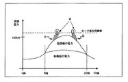
- Example 4 In Examples 1 to 3 described above, the storage battery is discharged only when the measured power value of the entire store exceeds the peak power target value of the store (area a in FIG. 29). When the peak power target value is lower than that, the power supply from the storage battery is stopped, and the power of the entire store is covered by the power supply from the system. Thereby, since the discharge frequency from a storage battery can be decreased, the lifetime of a storage battery can be extended.
- the measurement unit 110 obtains the power amount of the entire store measured by the wattmeter 510 and uses it as measurement data. Register in the database 120.
- FIG. 30 shows an example of measurement data registered in the database 120 from the measurement unit 110 regarding the power of the entire store.
- the amount of power for the entire store is registered by date, day, and time.
- the database 120 preferably holds at least measurement data for the past several months to one year.
- FIG. 31 shows an example of a table generated based on the measurement data shown in FIG.
- a database management unit (not shown) classifies past measurement data into months, days of the week, and time zones, and then calculates an average value of power for the entire store. And the average value of the electric power of the whole store is preserve
- the prediction unit 130 uses this table as basic data of a prediction model of the power amount of the entire store.
- the control unit uses the basic data to calculate a predicted power value of the entire store, and when the predicted power value exceeds a predetermined peak power target value, performs scheduling to execute the heat storage use operation, When the power measurement value of the entire facility exceeds the predicted power value, the storage battery is controlled to supply power to the facility.
- control unit 110 measurement unit, 120 database, 130 prediction unit, 140 control unit, 200 thermal storage air conditioning system, 250 power consuming equipment, 300 charger, 310 wattmeter, 400 storage battery, 410 AC / DC converter, 500 power Control system, 510 power meter, 1200 heat storage type showcase system
Landscapes
- Engineering & Computer Science (AREA)
- Mechanical Engineering (AREA)
- General Engineering & Computer Science (AREA)
- Combustion & Propulsion (AREA)
- Chemical & Material Sciences (AREA)
- Physics & Mathematics (AREA)
- Thermal Sciences (AREA)
- Signal Processing (AREA)
- Fuzzy Systems (AREA)
- Mathematical Physics (AREA)
- Transportation (AREA)
- Power Engineering (AREA)
- Sustainable Energy (AREA)
- Sustainable Development (AREA)
- Life Sciences & Earth Sciences (AREA)
- Air Conditioning Control Device (AREA)
- Charge And Discharge Circuits For Batteries Or The Like (AREA)
Abstract
【課題】施設の最大ピーク電力を抑制する。 【解決手段】蓄熱式空調システム200と、蓄電池400と、電気自動車への充電用の充電器300とが設置された施設の制御装置100において、予測部130は、電気自動車への充電電力を予測する。制御部140は、予測部130による予測結果にもとづいて、蓄熱式空調システム200の蓄熱および放熱を制御する。制御部140は、電気自動車への充電電力が予測部130による予測値を超えたとき、蓄電池400に蓄電された電力を使用するよう制御する。
Description
本発明は、蓄熱式空調システムと蓄電池が設置された施設および蓄熱式ショーケースシステムと蓄電池が設置された施設の制御装置に関する。
スーパーマーケットやコンビニエンスストアなどの店舗に設置された空調機の消費電力を削減する方法として、蓄熱式空調システムが知られている。蓄熱式空調システムの応用形態として、蓄電池と蓄熱槽を併用するシステムも提案されている(例えば、特許文献1参照)。このシステムにおいて、蓄電池と蓄熱槽に蓄積されたエネルギーを利用する場合の選択方法として、以下に挙げる2つの方法が考えられる。
第1の方法は、空調負荷を予測計算し、蓄熱槽に蓄熱されたエネルギーを利用して運転した場合の空調消費電力と、蓄電池に充電されたエネルギーを利用して運転した場合の空調消費電力とを算出する。そして、前者の空調運転費用と後者の空調運転費用とを比較し、安価なほうを選択する。
第2の方法は、冷房運転期間(一般的に、日本では5月~10月)に、蓄熱槽に蓄熱されたエネルギーを利用し、それ以外の期間に、蓄電池に充電されたエネルギーを利用する。
この蓄電池と蓄熱槽を併用するシステムは、蓄熱式空調機や蓄熱式ショーケースの運転費用やエネルギーを蓄積保持するための費用を安価にでき、蓄熱式空調機や蓄熱式ショーケースシステムを効率よく運転できるという点において、一定の効果がある。
ところで近年、電気自動車(以下適宜、EVと表記する)が普及しはじめており、スーパーマーケットやコンビニエンスストアなどの店舗にも、今後、EV充電設備が設置されることが予想される。それに伴い、店舗への来客者がEV充電設備を使用することにより、その店舗のEV充電時間帯の消費電力量が大きくなると予測される。
店舗にEV充電設備が設置された場合、不定期に発生するEV充電電力需要の増加により、店舗のピーク電力が、EV充電設備設置前と異なるパターンで発生することが予測される。すなわち、EV充電設備設置前と比較し、ピーク電力の発生時間帯および大きさの傾向が変化すると予測される。
このようなケースを想定した場合、上述した蓄電池と蓄熱槽を併用するシステムでは、EVの充電電力需要に伴うピーク電力の増大に対して、十分に対応することは困難である。
本発明はこうした状況に鑑みなされたものであり、その目的は、施設の最大ピーク電力を抑制する技術を提供することにある。
本発明のある態様の蓄熱式空調システムと蓄電池の制御装置は、蓄熱式空調システムと、蓄電池と、電気自動車への充電用の充電器とが設置された施設の制御装置であって、電気自動車への充電電力を予測する予測部と、予測部による予測結果にもとづいて、蓄熱式空調システムの蓄熱および放熱を制御する制御部と、を備える。制御部は、電気自動車への充電電力が予測部による予測値を超えたとき、蓄電池に蓄電された電力を使用するよう制御する。
また、本発明のある態様の蓄熱式ショーケースシステムと蓄電池の制御装置は、蓄熱式ショーケースシステムと、蓄電池と、電気自動車への充電用の充電器とが設置された施設の制御装置であって、電気自動車への充電電力を予測する予測部と、予測部による予測結果にもとづいて、蓄熱式ショーケースシステムの蓄熱および放熱を制御する制御部と、を備える。制御部は、電気自動車への充電電力が予測部による予測値を超えたとき、蓄電池に蓄電された電力を使用するよう制御する。
なお、以上の構成要素の任意の組み合わせ、本発明の表現を方法、装置、システム、記録媒体、コンピュータプログラム等の間で変換したものもまた、本発明の態様として有効である。
本発明によれば、施設の最大ピーク電力を抑制する技術を提供することにある。
(実施例1)
まず、本発明の実施の形態を詳細に説明する前に、本発明の実施の形態の概要を述べる。
図1は、EV充電電力が発生した場合の店舗電力の推移を示す。この店舗電力の推移は夏季期間の推移である。空調機の電力を示す曲線に積み重ねられている棒状の表記がEV充電電力を示している。図1では、空調機のピーク電力は約200kW程度である。EV充電電力には、緩やかな変化分と急激な変化分がある。緩やかな変化分は、確定的で予測可能な変化分である(領域b参照)。急激な変化分は、突発的で予測困難な変化分である(囲みa参照)。
まず、本発明の実施の形態を詳細に説明する前に、本発明の実施の形態の概要を述べる。
図1は、EV充電電力が発生した場合の店舗電力の推移を示す。この店舗電力の推移は夏季期間の推移である。空調機の電力を示す曲線に積み重ねられている棒状の表記がEV充電電力を示している。図1では、空調機のピーク電力は約200kW程度である。EV充電電力には、緩やかな変化分と急激な変化分がある。緩やかな変化分は、確定的で予測可能な変化分である(領域b参照)。急激な変化分は、突発的で予測困難な変化分である(囲みa参照)。
上述した蓄電池と蓄熱槽を併用するシステムでは、空調機の負荷を正確に予測できたとしても、EV充電電力需要に関連するピーク電力を削減することは難しい。特に、上述した急激な変化分に対応して上昇するピーク電力を削減することは難しい。
以下、EVの充電電力需要を2つに分類して考える。上記緩やかな変化分に対応する充電電力需要と、上記急激な変化分に対応する充電電力需要である。前者は電力予測がある程度可能であり、曜日や時間帯により、ある程度決定される充電電力需要である(以下適宜、EVパワー1という)。EVパワー1に対しては基本的に蓄熱式空調システムによる空調電力の削減で対応する。
後者は電力予測が困難であり、確率的および突発的に発生する充電電力需要である(以下適宜、EVパワー2という)。EVパワー2に対しては基本的に蓄電池に蓄電された電力で対応する。変化速度が速い電力需要に対しては、効果が現れるまでにある程度の時間が必要な、蓄熱式空調システムによる空調電力の削減で対応するのは難しいためである。
図2は、本発明の実施の形態に係る電力制御システム500の構成を示すブロック図である。電力制御システム500は、施設内外の機器に供給されるべき電力を制御する。電力制御システム500は、制御装置100、蓄熱式空調システム200、電力消費機器250(例えば、照明、ショーケース、冷凍機など。なお、蓄熱式空調システム200は除かれる)、EV用の充電器300、電力計310、蓄電池400、AC/DC変換器410および電力計510を備える。
電力計510は、商用電源(AC電源)からの受電電力を計測し、図示しない電力会社による課金の基礎データとなる。電力計310は、充電器300からEVに充電された電力量を計測し、制御装置100(より厳密には後述する計測部110)に出力する。
AC/DC変換器410は、商用電源から供給される交流電力を直流電力に変換して、蓄電池400に供給する。また、蓄電池400から供給される直流電力を交流電力に変換して、施設の電力系統に供給する。
蓄電池400には、リチウムイオン電池、ニッケル水素電池、鉛電池等を採用することができる。特に、リチウムイオン電池は、軽量、高容量および高出力であるため、注目されている。蓄電池400は、施設に設置されている電力供給が必要なすべての設備(本実施の形態では、充電器300、蓄熱式空調システム200、電力消費機器250)に電力供給可能である。
制御装置100は、計測部110、データベース120、予測部130および制御部140を備える。これらの構成は、ハードウェア的には、任意のプロセッサ、メモリ、その他のLSIで実現でき、ソフトウェア的にはメモリにロードされたプログラムなどによって実現されるが、ここではそれらの連携によって実現される機能ブロックを描いている。したがって、これらの機能ブロックがハードウェアのみ、ソフトウェアのみ、またはそれらの組み合わせによっていろいろな形で実現できることは、当業者には理解されるところである。
計測部110は、電力計310により計測されたEV充電電力量を取得し、計測データとしてデータベース120に登録する。
図3は、計測部110からデータベース120に登録される計測データの一例を示す図である。年月日、曜日および時刻別に、電力計310により計測されたEV充電電力量が登録される。データベース120には、少なくとも過去数カ月分~1年分程度の計測データが保持されることが望ましい。
図4は、図3に示した計測データをもとに生成されるテーブルの一例を示す図である。図示しないデータベース管理部は、過去計測データを、月、曜日、時間帯に分類した後、EV充電電力の平均値を算出する。そして、EV需要電力の平均値を、月、曜日、時間帯を検索キーとして、テーブル形式で保存する。図4に示すテーブルは、店舗の営業時間帯における、月曜日~日曜日までの1時間毎の当該平均値を保存したものである。予測部130はこのテーブルを、EVパワー1の予測モデルの基礎データとする。
ここで、どの程度の空調消費電力が発生した場合に、何台分のEV充電電力を蓄熱式空調システムによる節電効果により対応できるかに関する簡易試算を挙げる。前提として、空調機電力については、大型店舗を想定し、その店舗に蓄熱式空調システムが10系統設置されているとする。夏季のピーク時には約200kWの空調消費電力があるとする。
EV用の充電器における消費電力については、1台のEVが充電する場合に、充電器で約5kWの電力消費があるとする。そして、EVの電池容量を10kWhとし、2時間かけて充電すると仮定する。したがって、EVが10台同時に充電する場合、EV充電施設で、約50kW消費することになる。蓄熱利用運転(放熱運転ともいう)により、蓄熱式空調システムのCOP(Coefficient Of Performance)が28%向上すると仮定する。
上述した前提にしたがうと、大型店舗では夏季の電力ピーク時に約200kWの空調消費電力が発生し、EVが10台同時に充電すると、EV充電器の充電消費電力は約50kWになる。
一方、蓄熱利用運転により、空調機のCOPが約30%向上するため、空調機の削減電力は、空調消費電力200kW×0.3=60kWとなる。つまり、約200kWの空調消費電力が発生する店舗の場合、最大10台程度のEV充電電力需要を、蓄熱式空調システムによる空調電力の削減効果により対応することができるという試算結果になる。ただし、この試算は一例であり、本明細書はこの試算に限定されるものではない。
図2に戻り、予測部130は、データベース120を参照して、EVへの充電電力の推移を予測する。図4に示したテーブルが構築されている場合、予測部130は、予測すべき日の、月、曜日および時間帯をキーに、予測値とすべきEV充電電力需要を取得する。
図5は、EV充電電力予測値の一例を示す図である。
図2に戻り、制御部140は、予測部130による予測結果にもとづいて、蓄熱式空調システム200の蓄熱および放熱を制御する。制御部140は、EVへの充電電力が予測部130による予測値を超えたとき、蓄電池400に蓄電された電力を使用するよう制御する。より具体的には、EVへの充電電力の計測値と、EVへの充電電力の予測値とを比較し、当該計測値が当該予測値より大きい場合、または両者の差分が所定の閾値を超えた場合、蓄電池400に蓄電された電力を使用するよう制御する。
基本的に、制御部140はEVへの充電電力が予測範囲内で推移している時間帯には、蓄熱式空調システム200の蓄熱利用運転により対応し、予測範囲を超えて推移している時間帯には、蓄電池400に蓄電された電力により対応する。
制御部140は、蓄熱式空調システム200を蓄熱利用運転する際、EVへの充電電力の予測値に応じて、蓄熱利用運転する空調系統の数を変更してもよいし、蓄熱式空調システム200内の空調系統で循環する冷媒の過冷却度を変更してもよい。
図6は、蓄熱式空調システム200の構成例を示す図である。ここでは、個別分散型の蓄熱式空調システムに関する冷媒回路図の一例を示している。また、蓄熱式空調システム200がn(nは自然数)系統存在する例(図6では3系統)を示している。なお、ここでは複数の蓄熱式空調システムが配置されることにより、複数の空調機が配置される例を示しているが、一つの蓄熱ユニットが共有されることにより、複数の空調機が配置される構成であってもよい。
蓄熱式空調システム200aは、室外ユニット10、蓄熱ユニット20および室内ユニット30を備える。室外ユニット10は、圧縮機11、四方弁12および室外交換器13を含む。蓄熱ユニット20は、膨張弁21、開閉弁22、開閉弁23、蓄熱槽24、開閉弁25、開閉弁26および膨張弁27を含む。室内ユニット30は室内熱交換器31を含む。蓄熱槽24は図示しない蓄熱用熱交換器を含む。この冷媒回路では、3種類の冷房運転(すなわち、通常冷房運転、氷蓄熱運転および氷蓄熱利用運転)が可能である。1つの空調系統は、室内熱交換器、室外熱交換器、圧縮機が冷媒配管により接続されて構成されている。
通常冷房運転では、開閉弁22、開閉弁23、開閉弁25および開閉弁26はすべて閉じられ、蓄熱槽24は使用されない。すなわち、圧縮機11、四方弁12、室外交換器13、膨張弁21、膨張弁27および室内熱交換器31が環状に繋がれた冷媒循環経路が形成され、その経路を冷媒が循環することにより、室内熱交換器31により熱交換され、室内の温度を下げることができる。通常冷房運転では、商用電源から供給される電力により運転される。
氷蓄熱運転では、開閉弁23および開閉弁25が閉じられ、開閉弁22および開閉弁26が開かれる。すなわち、圧縮機11、四方弁12、室外交換器13、膨張弁21、開閉弁22、蓄熱槽24および開閉弁26が環状に繋がれた冷媒循環経路が形成され、その経路を冷媒が循環することにより、蓄熱槽24に氷が作られる。
氷蓄熱冷房運転では、開閉弁22および開閉弁26が閉じられ、開閉弁23および開閉弁25が開かれる。すなわち、圧縮機11、四方弁12、室外交換器13、膨張弁21、膨張弁27、開閉弁23、蓄熱槽24、開閉弁25、膨張弁27および室内熱交換器31が環状に繋がれた冷媒循環経路が形成され、その経路を冷媒が循環することにより、室内熱交換器31により熱交換され、室内の温度を下げることができる。氷蓄熱冷房運転では、蓄熱槽24に蓄熱されたエネルギーにより運転される。
蓄熱式空調システム200bおよび蓄熱式空調システム200cについても同様の構成である。上述したように、蓄熱式空調システム200の能力制御方法(すなわち、空調電力の削減量の大きさを調整する方法)として、2種類挙げられる。台数制御と過冷却度制御である。
台数制御の場合、制御部140は削減すべき空調電力に応じて、蓄熱利用運転する空調系統の数を制御する。1つの空調系統は、室内熱交換器、室外熱交換器、圧縮機が冷媒配管により接続されて構成されている。施設にはこの空調系統が複数存在している。台数制御の場合、制御部140は削減すべき空調電力に応じて、蓄熱利用運転する空調系統の数を制御する。今回の実施例において、より具体的には、各蓄熱式空調システム200a~cに、通常冷房運転するか、氷蓄熱冷房運転するか、運転しないかを指定する。
過冷却度制御の場合、制御部140は削減すべき空調電力に応じて、空調系統の過冷却度を制御する。空調削減電力を大きくしたい場合(すなわち、空調効率のアップ率を上げたい場合)、過冷却度を高く設定する。反対に、空調削減電力を小さくしたい場合(すなわち、空調効率のアップ率を下げたい場合)、過冷却度を低く設定する。
より具体的には、制御部140は、蓄熱槽24内の蓄熱用熱交換器に流れる冷媒流量と、蓄熱槽24をバイパスする冷媒流量との割合を、開閉弁25および開閉弁23で制御することにより、冷媒の過冷却度を制御する。制御部140は、過冷却度を変更する場合、各蓄熱式空調システム200a~cの開閉弁25および開閉弁23に開閉率を指定するための制御信号を出力する。
なお、図6に示す冷媒回路は一例であり、蓄熱槽への冷熱蓄熱専用の冷凍機と、空調系統の冷媒との熱交換用の、冷水やブラインを備えたタイプの冷媒回路を用いてもよい。その場合、空調系統の冷媒と熱交換を行う冷水やブラインの流量を制御して、蓄熱利用運転を行う空調系統の過冷却度や蓄熱利用運転を行う空調系統の数を制御することもできる。また、上述した例では、1つの空調系統毎に1つの蓄熱槽が存在しているが、複数の空調系統で蓄熱槽を共用する構成の冷媒回路を用いてもよい。
以下、本発明の実施の形態に係る蓄熱式空調システム200と蓄電池400の制御方法の一例について、タイミングチャートを参照しながら説明する。図7は、蓄電池400の電力制御の一例を示すタイミングチャートである。図8は、蓄熱式空調システム200の蓄熱運転制御の一例を示すタイミングチャートである。
蓄熱式空調システム200の蓄熱運転制御において、予測部130は制御日の前日に、蓄熱槽24への蓄熱量を予測し、制御部140は制御日の蓄熱利用運転のスケジュールを決定する(図8のf参照)。ここで、制御日とは、蓄熱利用運転制御と蓄電池制御との併用制御を実施する対象日を指す。次に、制御部140は制御日の夜間時間帯に、予測部130により予測された蓄熱量を蓄熱槽24に蓄熱する(図8のg参照)。次に、制御部140は制御日当日に蓄熱利用運転制御を実行する(図8のh参照)。また、制御部140は制御日当日に蓄電池400の電力制御を実行する(図7参照)。このように、制御部140はEVパワー1に対しては、蓄熱利用運転制御で対処し、EVパワー2に対しては、蓄電池400の電力制御で対処する。
蓄熱式空調システム200の台数制御による蓄熱利用運転制御について説明する。図9は、EV充電電力予測値と蓄熱運転する空調系統の台数との対応関係を記述したテーブルの一例を示す図である。図10は、蓄熱式空調システム200の台数制御の一例を示すタイミングチャートである。蓄熱運転する空調系統の台数が増えるということは、蓄熱槽24からの放熱量が大きく、蓄熱利用運転による空調電力の削減量が大きいことを示す。したがって、蓄熱運転する空調系統の台数を増やすことにより、空調負荷だけでなく、EVパワー1にも対応することができる。
次に、蓄熱式空調システム200の過冷却度制御による蓄熱利用運転制御について説明する。図11は、EV充電電力予測値と蓄熱運転する空調系統の過冷却度との対応関係を記述したテーブルの一例を示す図である。図12は、蓄熱式空調システム200の過冷却度制御の一例を示すタイミングチャートである。過冷却度が大きいということは、蓄熱槽24からの放熱量が大きく、蓄熱利用運転による空調電力の削減量が大きいことを示す。したがって、過冷却度を大きくすることにより、空調負荷だけでなく、EVパワー1にも対応することができる。
図13は、図1と比較すべき、EV充電電力が発生した場合の店舗電力の推移を示す。曲線状の点線に囲まれた領域は、蓄熱運転制御により削減された電力を示している。棒状の点線領域は蓄電池400からの電力供給により賄われた電力を示している。本実施の形態に係る制御方法を適用することにより、ピーク電力を450kW以内に抑えることに成功したことを示している。これに対し、図1では450kWを超える時間帯が発生している。
以下、本発明の実施の形態に係る制御装置100の動作についてフローチャートを参照しながら説明する。図14は、本発明の実施の形態に係る制御装置100による、蓄熱式空調システム200および蓄電池400の全体制御を説明するためのフローチャートである。このフローチャートは当該制御の1サイクル分を示すものである。
まず、制御部140は、蓄熱利用運転制御と蓄電池制御との併用制御を実施する日時(より具体的には、制御日とその開始時刻および終了時刻)を決定する(S10)。
次に、予測部130は、蓄熱槽24への蓄熱量を制御開始日時前(例えば、制御開始日時の24時間前)に予測する(S20)。ここで、空調負荷に関する蓄熱量について考える。空調負荷(例えば、換気負荷、日射熱負荷など)に対応した、空調電力削減のための蓄熱量の予測方法については、既存の一般的な技術を利用する。次に、EVパワー1に関する蓄熱量について考える。EV充電電力需要の中で、ある程度予測可能で、かつ緩やかな充電電力変化に関しては、その充電電力を予測する。この充電電力需要は、曜日や時間帯により、ある程度、予測することが可能である。そして、この予測された充電電力に相当する蓄熱量を計算する。当該蓄熱量は空調機の削減電力に相当する。EVパワー1の予測方法については、上述した図4に示したテーブルなどを基礎とする充電電力予測モデルを利用することができる。そして、空調負荷に関する蓄熱量と、EVパワー1に関する蓄熱量を合計したものを合計蓄熱量とする。
次に、制御部140は蓄熱利用運転制御のスケジュールを、制御開始日時前(例えば、制御開始日時の24時間前)に予測する(S30)。当該スケジュールは、どの時刻にどの程度、空調電力を削減するかを規定したものである。制御部140は、上述したEVパワー1の充電電力予測結果(より厳密には、時間帯別のEVパワー1の充電電力の変化)を利用して、EVパワー1の充電電力に対応した空調削減電力が得られるように、制御日の蓄熱利用運転パターンを決定する。当該蓄熱利用運転パターンとして、台数制御の運転スケジュールまたは過冷却度制御の運転スケジューリングが挙げられる。
次に、制御部140は、制御開始前の夜間時間帯において予測された蓄熱量を蓄熱槽24へ蓄熱するよう制御する(S40)。例えば、予測された蓄熱量を、前日の夜間時間帯に蓄熱するように蓄熱式空調システム200を運転する。図6に示した冷媒回路では、空調系統毎に蓄熱槽が存在しているので、蓄熱利用運転する空調系統の蓄熱槽24に冷熱を蓄熱しておく必要があり、該当する空調系統の蓄熱槽24に冷熱を蓄熱する。台数制御を利用する場合、台数制御を行う空調系統の蓄熱槽24に冷熱を蓄熱する。過冷却度制御を利用する場合、過冷却度制御を行う空調系統の蓄熱槽24に冷熱を蓄熱する。
制御部140は、制御日に上記蓄熱利用運転パターンに従って、上記台数制御または上記過冷却度制御を実施する(S50)。より具体的には、制御部140は、予め保持されている運転タイムチャート情報に従って、時間毎に、必要な命令情報を蓄熱ユニット20に送信する。
台数制御の場合、蓄熱運転する空調系統の台数のスケジューリング(すなわち、台数の増加減少)に応じて、蓄熱運転する台数(すなわち、蓄熱槽に貯めた冷熱を放熱する空調系統の台数)を制御する。具体的には、制御部140は当該スケジューリングに従って、蓄熱運転する系統に蓄熱運転開始の制御信号を送信する。この制御信号に従い、該当する空調系統は氷蓄熱利用冷房運転を行う。
過冷却度制御の場合、氷蓄熱利用運転する空調系統の過冷却度のスケジューリングに応じて、蓄熱した冷熱を放熱する。具体的には、制御部140は当該スケジューリングに従って、蓄熱運転する空調系統毎に所定の過冷却度の制御信号を送信する。当該制御信号に従い、該当する空調系統は過冷却度の温度を調整するために、蓄熱槽24に流れる冷媒流量を、開閉弁25、23により調整する。蓄熱槽24の蓄熱熱交換器に流れる冷媒流量と、蓄熱熱交換器をバイパスする冷媒流量の割合を、開閉弁25、23により調整することにより、過冷却度を調整する。
制御部140は、制御日に蓄電池400の電力制御を実施する(S60)。充電器300によるEV充電電力を計測して、計測したEV充電電力と、該当時間のEVパワー1の予測値とを比較し、計測電力が予測電力を超えていれば、蓄電池400から電力を供給する。
制御部140は、ステップS50およびステップS60の制御を、蓄熱利用運転制御と蓄電池制御との併用制御の終了時刻に到達するまで(S70のN)、繰り返し実行する。終了時刻に到達すると(S70のY)、制御日の当該併用制御を終了する。
図15は、図14のフローチャートのステップS20における予測処理をより詳細に説明するためのフローチャートである。予測部130は、空調負荷に対する蓄熱量を予測する(S21)。例えば、外気温度、ここ数日の空調負荷の平均値、または前日の空調負荷を利用して、当日の空調負荷を予測する。そして、当日の予測空調負荷をもとに、空調電力削減に必要な蓄熱量を決定する。
次に、予測部130は、EVパワー1に対する蓄熱量を予測する(S22)。例えば、図4に示したテーブルを基礎とするEV充電電力予測モデルに対して、制御日当日の月、曜日および時間帯を入力し、当日の時間帯別のEV充電電力の予測値を取得する。そして、このEV充電電力の予測値に相当する空調機の削減電力が得られる蓄熱量(すなわち、蓄熱利用運転に必要な蓄熱量)を計算する。例えば、過去の蓄熱利用運転時の計測データなどから、蓄熱量[kJ]に対する空調削減電力量[kWh]の関係式をαと定義し、(EV充電電力の予測値から計算した、制御日のEV充電電力量)/αを計算して、当該蓄熱量を求める。
次に、予測部130は、空調負荷に関する蓄熱量と、EVパワー1に関する蓄熱量とを合算し、合計蓄熱量を決定する(S23)。
図16は、図14のフローチャートのステップS30におけるスケジュール決定処理をより詳細に説明するためのフローチャートである。制御部140は、図14のステップS20により予測された、EV充電電力予測データ(より厳密には、時間帯別の充電電力の推移)を取得する(S31)。
次に、制御部140は上記EV充電電力予測データを利用して、EV充電電力に対応する空調削減電力を、蓄熱利用運転による空調機の効率向上により賄えるよう、当日の蓄熱利用運転パターンを決定する(S32)。
まず、台数制御による蓄熱利用運転パターンの決定方法について説明する。制御部140はEV充電電力需要に応じて、蓄熱利用運転する空調系統の台数を制御する。例えば、EV充電電力需要を複数の段階に分類して、その大きさに応じて、蓄熱利用運転する台数を決定する。具体的には、EV充電電力需要が大きい場合、蓄熱利用運転する空調系統の台数を増やし、EV充電電力需要が小さい場合、蓄熱利用運転する空調系統の台数を少なくする。例えば、図9に示したように、EV充電電力需要の大きさと蓄熱利用運転する空調系統の台数とを対応づけたテーブルを作成し、EV予測充電電力(例えば、図5参照)に応じて、蓄熱利用運転する空調系統の台数のスケジューリングを図10に示したように決定する。当該スケジューリングは、どの時間帯に何台、蓄熱利用運転するかを示すものである。
次に、冷媒の過冷却度制御による蓄熱利用運転パターンの決定方法について説明する。制御部140はEV充電電力需要に応じて、蓄熱利用運転する空調系統の過冷却度を決定する。具体的には、EV充電電力需要が大きい場合、過冷却度を大きくし、EV充電電力需要が小さい場合、過冷却度を小さくする。例えば、図11に示したように、EV予測充電電力の大きさと過冷却度を対応づけたテーブルを作成し、EV予測充電電力(例えば、図5参照)に応じて、蓄熱利用運転する空調系統の過冷却度のスケジューリングを図12に示したように決定する。当該スケジュールは、どの時間帯にどれくらいの過冷却度に設定するかを示すものである。なお、過冷却度を指定するのは、特定の空調系統だけであってもよいし、すべての空調系統であってもよい。
以上の情報(すなわち、台数制御または過冷却度制に関するスケジューリング情報)は、制御装置100の図示しないメモリに予め蓄積される。
図17は、図14のフローチャートのステップS60における蓄電池制御をより詳細に説明するためのフローチャートである。電力計310はEV充電電力を計測し、EV充電電力計測値として計測部110に出力する(S61)。予測部130は、上記EV充電電力予測モデルから現時点のEV充電電力予測値を算出する(S62)。上述したように、現時点のEV充電電力予測値は、月、曜日および時間帯を指定することにより取得することができる。
制御部140は、該当日時のEV充電電力予測値と、上記EV充電電力計測値とを比較する(S63)。当該計測値が当該予測値を超えている場合(S63のY)、蓄電池400に対して、電力系統への放電命令を出力する(S64)。これにより、電力系統に蓄電池400から電力が供給される。
当該計測値が当該予測値を超えていない場合(S63のN)、制御部140は、蓄電池40から電力系統へ放電しているか否か判定する(S65)。放電している場合(S65のY)、蓄電池400に対して電力系統への放電停止命令を出力する(S66)。これにより、電力系統への蓄電池400からの放電が停止する。
放電していない場合(S65のN)、制御部140は、蓄電池制御の終了時刻に到達するまで(S67のN)、ステップS61に遷移し、当該蓄電池制御を繰り返し実行する。終了時刻に到達すると(S67のY)、当該蓄電池制御を終了する。
以上説明したように本実施の形態によれば、EVの充電電力需要の特徴を考慮した上で、ある程度予測可能な緩やかな充電電力変化には蓄熱空調システムで対応し、予測困難な急激な充電電力変化には蓄電池で対応することにより、EV充電電力需要の増加に伴う店舗のピーク電力を削減し、店舗の電力を平準化することができる。また、深夜時間帯に蓄熱することにより、店舗全体の電気料金を安くすることができる。
以上、本発明を実施の形態をもとに説明した。この実施の形態は例示であり、それらの各構成要素や各処理プロセスの組合せにいろいろな変形例が可能なこと、またそうした変形例も本発明の範囲にあることは当業者に理解されるところである。
図4に示したテーブルは、過去計測データを月、曜日、時間帯を検索キーとしたが、図示しないデータベース管理部は、気象条件(例えば、外気温、湿度)を外部サーバから取得し、検索キーに加えてもよい。この場合、EV充電電力需要をより高精度に予測することができる。
(実施例2)
まず、本発明の実施の形態を詳細に説明する前に、本発明の実施の形態の概要を述べる。
図18は、EV充電電力が発生した場合の店舗電力の推移を示す。この店舗電力の推移は夏季期間の推移である。ショーケースの電力を示す曲線に積み重ねられている棒状の表記がEV充電電力を示している。図18では、ショーケース/冷凍機のピーク電力は約200kW程度である。EV充電電力には、緩やかな変化分と急激な変化分がある。緩やかな変化分は、確定的で予測可能な変化分である(領域b参照)。急激な変化分は、突発的で予測困難な変化分である(囲みa参照)。
まず、本発明の実施の形態を詳細に説明する前に、本発明の実施の形態の概要を述べる。
図18は、EV充電電力が発生した場合の店舗電力の推移を示す。この店舗電力の推移は夏季期間の推移である。ショーケースの電力を示す曲線に積み重ねられている棒状の表記がEV充電電力を示している。図18では、ショーケース/冷凍機のピーク電力は約200kW程度である。EV充電電力には、緩やかな変化分と急激な変化分がある。緩やかな変化分は、確定的で予測可能な変化分である(領域b参照)。急激な変化分は、突発的で予測困難な変化分である(囲みa参照)。
上述した蓄電池と蓄熱槽を併用するシステムでは、ショーケースの負荷を正確に予測できたとしても、EV充電電力需要に関連するピーク電力を削減することは難しい。特に、上述した急激な変化分に対応して上昇するピーク電力を削減することは難しい。
以下、EVの充電電力需要を2つに分類して考える。上記緩やかな変化分に対応する充電電力需要と、上記急激な変化分に対応する充電電力需要である。前者は電力予測がある程度可能であり、曜日や時間帯により、ある程度決定される充電電力需要である(以下適宜、EVパワー1という)。EVパワー1に対しては基本的に蓄熱式ショーケースシステムによるショーケース/冷凍機の電力の削減で対応する。
後者は電力予測が困難であり、確率的および突発的に発生する充電電力需要である(以下適宜、EVパワー2という)。EVパワー2に対しては基本的に蓄電池に蓄電された電力で対応する。変化速度が速い電力需要に対しては、効果が現れるまでにある程度の時間が必要な、蓄熱式ショーケースシステムによるショーケース/冷凍機の電力の削減で対応するのは難しいためである。
図19は、本発明の実施の形態に係る電力制御システム5000の構成を示すブロック図である。電力制御システム5000は、施設内外の機器に供給されるべき電力を制御する。電力制御システム5000は、制御装置100、蓄熱式ショーケースシステム1200、電力消費機器1250(例えば、照明、空調など。なお、蓄熱式ショーケースシステム1200は除かれる)、EV用の充電器300、電力計310、蓄電池400、AC/DC変換器410および電力計510を備える。
電力計510は、商用電源(AC電源)からの受電電力を計測し、図示しない電力会社による課金の基礎データとなる。電力計310は、充電器300からEVに充電された電力量を計測し、制御装置100(より厳密には後述する計測部110)に出力する。
AC/DC変換器410は、商用電源から供給される交流電力を直流電力に変換して、蓄電池400に供給する。また、蓄電池400から供給される直流電力を交流電力に変換して、施設の電力系統に供給する。
蓄電池400には、リチウムイオン電池、ニッケル水素電池、鉛電池等を採用することができる。特に、リチウムイオン電池は、軽量、高容量および高出力であるため、注目されている。蓄電池400は、施設に設置されている電力供給が必要なすべての設備(本実施の形態では、充電器300、蓄熱式ショーケースシステム1200、電力消費機器1250)に電力供給可能である。
制御装置100は、計測部110、データベース120、予測部130および制御部140を備える。これらの構成は、ハードウェア的には、任意のプロセッサ、メモリ、その他のLSIで実現でき、ソフトウェア的にはメモリにロードされたプログラムなどによって実現されるが、ここではそれらの連携によって実現される機能ブロックを描いている。したがって、これらの機能ブロックがハードウェアのみ、ソフトウェアのみ、またはそれらの組み合わせによっていろいろな形で実現できることは、当業者には理解されるところである。
計測部110は、電力計310により計測されたEV充電電力量を取得し、計測データとしてデータベース120に登録する。
図3は、計測部110からデータベース120に登録される計測データの一例を示す図である。年月日、曜日および時刻別に、電力計310により計測されたEV充電電力量が登録される。データベース120には、少なくとも過去数カ月分~1年分程度の計測データが保持されることが望ましい。
図4は、図3に示した計測データをもとに生成されるテーブルの一例を示す図である。図示しないデータベース管理部は、過去計測データを、月、曜日、時間帯に分類した後、EV充電電力の平均値を算出する。そして、EV需要電力の平均値を、月、曜日、時間帯を検索キーとして、テーブル形式で保存する。図4に示すテーブルは、店舗の営業時間帯における、月曜日~日曜日までの1時間毎の当該平均値を保存したものである。予測部130はこのテーブルを、EVパワー1の予測モデルの基礎データとする。
ここで、どの程度のショーケース/冷凍機の消費電力が発生した場合に、何台分のEV充電電力を蓄熱式ショーケースシステムによる節電効果により対応できるかに関する簡易試算を挙げる。前提として、ショーケース/冷凍機の電力については、大型店舗を想定し、その店舗に蓄熱式ショーケースシステムが10系統設置されているとする。夏季のピーク時には約200kWのショーケース/冷凍機の消費電力があるとする。
EV用の充電器における消費電力については、1台のEVが充電する場合に、充電器で約5kWの電力消費があるとする。そして、EVの電池容量を10kWhとし、2時間かけて充電すると仮定する。したがって、EVが10台同時に充電する場合、EV充電施設で、約50kW消費することになる。蓄熱利用運転(放熱運転ともいう)により、蓄熱式ショーケースシステムのCOP(Coefficient Of Performance)が28%向上すると仮定する。
上述した前提にしたがうと、大型店舗では夏季の電力ピーク時に約200kWのショーケース/冷凍機の消費電力が発生し、EVが10台同時に充電すると、EV充電器の充電消費電力は約50kWになる。
一方、蓄熱利用運転により、ショーケース/冷凍機のCOPが約30%向上するため、ショーケース/冷凍機の削減電力は、ショーケース/冷凍機の消費電力200kW×0.3=60kWとなる。つまり、約200kWのショーケース/冷凍機の消費電力が発生する店舗の場合、最大10台程度のEV充電電力需要を、蓄熱式ショーケースシステムによるショーケース/冷凍機の削減効果により対応することができるという試算結果になる。ただし、この試算は一例であり、本明細書はこの試算に限定されるものではない。
図19に戻り、予測部130は、データベース120を参照して、EVへの充電電力の推移を予測する。図4に示したテーブルが構築されている場合、予測部130は、予測すべき日の、月、曜日および時間帯をキーに、予測値とすべきEV充電電力需要を取得する。
図5は、EV充電電力予測値の一例を示す図である。
図19に戻り、制御部140は、予測部130による予測結果にもとづいて、蓄熱式ショーケースシステム1200の蓄熱および放熱を制御する。制御部140は、EVへの充電電力が予測部130による予測値を超えたとき、蓄電池400に蓄電された電力を使用するよう制御する。より具体的には、EVへの充電電力の計測値と、EVへの充電電力の予測値とを比較し、当該計測値が当該予測値より大きい場合、または両者の差分が所定の閾値を超えた場合、蓄電池400に蓄電された電力を使用するよう制御する。
基本的に、制御部140はEVへの充電電力が予測範囲内で推移している時間帯には、蓄熱式ショーケースシステム1200の蓄熱利用運転により対応し、予測範囲を超えて推移している時間帯には、蓄電池400に蓄電された電力により対応する。
制御部140は、蓄熱式ショーケースシステム1200を蓄熱利用運転する際、EVへの充電電力の予測値に応じて、蓄熱利用運転するショーケース系統の数を変更してもよいし、蓄熱式ショーケースシステム1200内のショーケース系統で循環する冷媒の過冷却度を変更してもよい。
図20は、蓄熱式ショーケースシステム1200の構成例を示す図である。ここでは、個別分散型の蓄熱式ショーケースシステムに関する冷媒回路図の一例を示している。また、蓄熱式ショーケースシステム1200がn(nは自然数)系統存在する例(図20では3系統)を示している。なお、ここでは複数の蓄熱式ショーケースシステムが配置されることにより、複数のショーケースが配置される例を示しているが、一つの蓄熱ユニットが共有されることにより、複数のショーケースが配置される構成であってもよい。
蓄熱式ショーケースシステム1200aは、冷凍機ユニット10、蓄熱ユニット201およびショーケースユニット301を備える。冷凍機ユニット10は、圧縮機11、および室外交換器13を含む。蓄熱ユニット201は、膨張弁21、開閉弁22、開閉弁23、蓄熱槽24、開閉弁25、開閉弁26および膨張弁27を含む。ショーケースユニット301は室内熱交換器31を含む。蓄熱槽24は図示しない蓄熱用熱交換器を含む。この冷媒回路では、3種類の冷却運転(すなわち、通常冷却運転、氷蓄熱運転および氷蓄熱利用運転)が可能である。1つのショーケース系統は、室内熱交換器、室外熱交換器、圧縮機が冷媒配管により接続されて構成されている。
通常冷却運転では、開閉弁22、開閉弁23、開閉弁25および開閉弁26はすべて閉じられ、蓄熱槽24は使用されない。すなわち、圧縮機11、室外交換器13、膨張弁21、膨張弁27および室内熱交換器31が環状に繋がれた冷媒循環経路が形成され、その経路を冷媒が循環することにより、室内熱交換器31により熱交換され、ショーケース庫内の温度を下げることができる。通常冷却運転では、商用電源から供給される電力により運転される。
氷蓄熱運転では、開閉弁23および開閉弁25が閉じられ、開閉弁22および開閉弁26が開かれる。すなわち、圧縮機11、室外交換器13、膨張弁21、開閉弁22、蓄熱槽24および開閉弁26が環状に繋がれた冷媒循環経路が形成され、その経路を冷媒が循環することにより、蓄熱槽24に氷が作られる。
氷蓄熱冷却運転では、開閉弁22および開閉弁26が閉じられ、開閉弁23および開閉弁25が開かれる。すなわち、圧縮機11、室外交換器13、膨張弁21、膨張弁27、開閉弁23、蓄熱槽24、開閉弁25、膨張弁27および室内熱交換器31が環状に繋がれた冷媒循環経路が形成され、その経路を冷媒が循環することにより、室内熱交換器31により熱交換され、ショーケース庫内の温度を下げることができる。氷蓄熱冷却運転では、蓄熱槽24に蓄熱されたエネルギーにより運転される。
蓄熱式ショーケースシステム1200bおよび蓄熱式ショーケースシステム1200cについても同様の構成である。上述したように、蓄熱式ショーケースシステム1200の能力制御方法(すなわち、ショーケース/冷凍機の電力の削減量の大きさを調整する方法)として、2種類挙げられる。台数制御と過冷却度制御である。
台数制御の場合、制御部140は削減すべきショーケース/冷凍機の電力に応じて、蓄熱利用運転するショーケース系統の数を制御する。1つのショーケース系統は、室内熱交換器、室外熱交換器、圧縮機が冷媒配管により接続されて構成されている。施設にはこのショーケース系統が複数存在している。台数制御の場合、制御部140は削減すべきショーケース/冷凍機の電力に応じて、蓄熱利用運転するショーケース系統の数を制御する。今回の実施例において、より具体的には、各蓄熱式ショーケースシステム1200a~cに、通常冷却運転するか、氷蓄熱冷却運転するか、運転しないかを指定する。
過冷却度制御の場合、制御部140は削減すべきショーケース/冷凍機の電力に応じて、ショーケース系統の過冷却度を制御する。ショーケース/冷凍機の削減電力を大きくしたい場合(すなわち、効率のアップ率を上げたい場合)、過冷却度を高く設定する。反対に、ショーケース/冷凍機の削減電力を小さくしたい場合(すなわち、ショーケース効率のアップ率を下げたい場合)、過冷却度を低く設定する。
より具体的には、制御部140は、蓄熱槽24内の蓄熱用熱交換器に流れる冷媒流量と、蓄熱槽24をバイパスする冷媒流量との割合を、開閉弁25および開閉弁23で制御することにより、冷媒の過冷却度を制御する。制御部140は、過冷却度を変更する場合、各蓄熱式ショーケースシステム1200a~cの開閉弁25および開閉弁23に開閉率を指定するための制御信号を出力する。
なお、図20に示す冷媒回路は一例であり、蓄熱槽への冷熱蓄熱専用の冷凍機と、ショーケース系統の冷媒との熱交換用の、冷水やブラインを備えたタイプの冷媒回路を用いてもよい。その場合、ショーケース系統の冷媒と熱交換を行う冷水やブラインの流量を制御して、蓄熱利用運転を行うショーケース系統の過冷却度や蓄熱利用運転を行うショーケース系統の数を制御することもできる。また、上述した例では、1つのショーケース系統毎に1つの蓄熱槽が存在しているが、複数のショーケース系統で蓄熱槽を共用する構成の冷媒回路を用いてもよい。
以下、本発明の実施の形態に係る蓄熱式ショーケースシステム1200と蓄電池400の制御方法の一例について、タイミングチャートを参照しながら説明する。図21は、蓄電池400の電力制御の一例を示すタイミングチャートである。図22は、蓄熱式ショーケースシステム1200の蓄熱運転制御の一例を示すタイミングチャートである。
蓄熱式ショーケースシステム1200の蓄熱運転制御において、予測部130は制御日の前日に、蓄熱槽24への蓄熱量を予測し、制御部140は制御日の蓄熱利用運転のスケジュールを決定する(図22のf参照)。ここで、制御日とは、蓄熱利用運転制御と蓄電池制御との併用制御を実施する対象日を指す。次に、制御部140は制御日の夜間時間帯に、予測部130により予測された蓄熱量を蓄熱槽24に蓄熱する(図22のg参照)。次に、制御部140は制御日当日に蓄熱利用運転制御を実行する(図22のh参照)。また、制御部140は制御日当日に蓄電池400の電力制御を実行する(図21参照)。このように、制御部140はEVパワー1に対しては、蓄熱利用運転制御で対処し、EVパワー2に対しては、蓄電池400の電力制御で対処する。
蓄熱式ショーケースシステム1200の台数制御による蓄熱利用運転制御について説明する。図23は、EV充電電力予測値と蓄熱運転するショーケース系統の台数との対応関係を記述したテーブルの一例を示す図である。図24は、蓄熱式ショーケースシステム1200の台数制御の一例を示すタイミングチャートである。蓄熱運転するショーケース系統の台数が増えるということは、蓄熱槽24からの放熱量が大きく、蓄熱利用運転によるショーケース電力の削減量が大きいことを示す。したがって、蓄熱運転するショーケース系統の台数を増やすことにより、ショーケース負荷だけでなく、EVパワー1にも対応することができる。
次に、蓄熱式ショーケースシステム1200の過冷却度制御による蓄熱利用運転制御について説明する。図25は、EV充電電力予測値と蓄熱運転するショーケース系統の過冷却度との対応関係を記述したテーブルの一例を示す図である。図26は、蓄熱式ショーケースシステム1200の過冷却度制御の一例を示すタイミングチャートである。過冷却度が大きいということは、蓄熱槽24からの放熱量が大きく、蓄熱利用運転によるショーケース電力の削減量が大きいことを示す。したがって、過冷却度を大きくすることにより、ショーケース負荷だけでなく、EVパワー1にも対応することができる。
図27は、図1と比較すべき、EV充電電力が発生した場合の店舗電力の推移を示す。曲線状の点線に囲まれた領域は、蓄熱運転制御により削減された電力を示している。棒状の点線領域は蓄電池400からの電力供給により賄われた電力を示している。本実施の形態に係る制御方法を適用することにより、ピーク電力を450kW以内に抑えることに成功したことを示している。これに対し、図18では450kWを超える時間帯が発生している。
以下、本発明の実施の形態に係る制御装置100の動作についてフローチャートを参照しながら説明する。図14は、本発明の実施の形態に係る制御装置100による、蓄熱式ショーケースシステム1200および蓄電池400の全体制御を説明するためのフローチャートである。このフローチャートは当該制御の1サイクル分を示すものである。
まず、制御部140は、蓄熱利用運転制御と蓄電池制御との併用制御を実施する日時(より具体的には、制御日とその開始時刻および終了時刻)を決定する(S10)。
次に、予測部130は、蓄熱槽24への蓄熱量を制御開始日時前(例えば、制御開始日時の24時間前)に予測する(S20)。ここで、ショーケース負荷に関する蓄熱量について考える。ショーケース負荷(例えば、外気負荷など)に対応した、ショーケース/冷凍機の電力削減のための蓄熱量の予測方法については、既存の一般的な技術を利用する。次に、EVパワー1に関する蓄熱量について考える。EV充電電力需要の中で、ある程度予測可能で、かつ緩やかな充電電力変化に関しては、その充電電力を予測する。この充電電力需要は、曜日や時間帯により、ある程度、予測することが可能である。そして、この予測された充電電力に相当する蓄熱量を計算する。当該蓄熱量はショーケースの削減電力に相当する。EVパワー1の予測方法については、上述した図4に示したテーブルなどを基礎とする充電電力予測モデルを利用することができる。そして、ショーケース負荷に関する蓄熱量と、EVパワー1に関する蓄熱量を合計したものを合計蓄熱量とする。
次に、制御部140は蓄熱利用運転制御のスケジュールを、制御開始日時前(例えば、制御開始日時の24時間前)に予測する(S30)。当該スケジュールは、どの時刻にどの程度、ショーケース電力を削減するかを規定したものである。制御部140は、上述したEVパワー1の充電電力予測結果(より厳密には、時間帯別のEVパワー1の充電電力の変化)を利用して、EVパワー1の充電電力に対応したショーケース/冷凍機の削減電力が得られるように、制御日の蓄熱利用運転パターンを決定する。当該蓄熱利用運転パターンとして、台数制御の運転スケジュールまたは過冷却度制御の運転スケジューリングが挙げられる。
次に、制御部140は、制御開始前の夜間時間帯において予測された蓄熱量を蓄熱槽24へ蓄熱するよう制御する(S40)。例えば、予測された蓄熱量を、前日の夜間時間帯に蓄熱するように蓄熱式ショーケースシステム1200を運転する。図20に示した冷媒回路では、ショーケース系統毎に蓄熱槽が存在しているので、蓄熱利用運転するショーケース系統の蓄熱槽24に冷熱を蓄熱しておく必要があり、該当するショーケース系統の蓄熱槽24に冷熱を蓄熱する。台数制御を利用する場合、台数制御を行うショーケース系統の蓄熱槽24に冷熱を蓄熱する。過冷却度制御を利用する場合、過冷却度制御を行うショーケース系統の蓄熱槽24に冷熱を蓄熱する。
制御部140は、制御日に上記蓄熱利用運転パターンに従って、上記台数制御または上記過冷却度制御を実施する(S50)。より具体的には、制御部140は、予め保持されている運転タイムチャート情報に従って、各時間毎に、必要な命令情報を蓄熱ユニット20に送信する。
台数制御の場合、蓄熱運転するショーケース系統の台数のスケジューリング(すなわち、台数の増加減少)に応じて、蓄熱運転する台数(すなわち、蓄熱槽に貯めた冷熱を放熱するショーケース系統の台数)を制御する。具体的には、制御部140は当該スケジューリングに従って、蓄熱運転する系統に蓄熱運転開始の制御信号を送信する。この制御信号に従い、該当するショーケース系統は氷蓄熱利用冷却運転を行う。
過冷却度制御の場合、氷蓄熱利用運転するショーケース系統の過冷却度のスケジューリングに応じて、蓄熱した冷熱を放熱する。具体的には、制御部140は当該スケジューリングに従って、蓄熱運転するショーケース系統毎に所定の過冷却度の制御信号を送信する。当該制御信号に従い、該当するショーケース系統は過冷却度の温度を調整するために、蓄熱槽24に流れる冷媒流量を、開閉弁25、23により調整する。蓄熱槽24の蓄熱熱交換器に流れる冷媒流量と、蓄熱熱交換器をバイパスする冷媒流量の割合を、開閉弁25、23により調整することにより、過冷却度を調整する。
制御部140は、制御日に蓄電池400の電力制御を実施する(S60)。充電器300によるEV充電電力を計測して、計測したEV充電電力と、該当時間のEVパワー1の予測値とを比較し、計測電力が予測電力を超えていれば、蓄電池400から電力を供給する。
制御部140は、ステップS50およびステップS60の制御を、蓄熱利用運転制御と蓄電池制御との併用制御の終了時刻に到達するまで(S70のN)、繰り返し実行する。終了時刻に到達すると(S70のY)、制御日の当該併用制御を終了する。
図28は、図14のフローチャートのステップS20における予測処理をより詳細に説明するためのフローチャートである。予測部130は、ショーケース負荷に対する蓄熱量を予測する(S21)。例えば、店内の温度湿度や、外気の温度湿度、ここ数日のショーケース負荷の平均値、または前日のショーケース負荷を利用して、当日のショーケース負荷を予測する。そして、当日の予測ショーケース負荷をもとに、ショーケース電力削減に必要な蓄熱量を決定する。
次に、予測部130は、EVパワー1に対する蓄熱量を予測する(S22)。例えば、図4に示したテーブルを基礎とするEV充電電力予測モデルに対して、制御日当日の月、曜日および時間帯を入力し、当日の時間帯別のEV充電電力の予測値を取得する。そして、このEV充電電力の予測値に相当するショーケース/冷凍機の削減電力が得られる蓄熱量(すなわち、蓄熱利用運転に必要な蓄熱量)を計算する。例えば、過去の蓄熱利用運転時の計測データなどから、蓄熱量[kJ]に対するショーケース/冷凍機の削減電力量[kWh]の関係式をαと定義し、(EV充電電力の予測値から計算した、制御日のEV充電電力量)/αを計算して、当該蓄熱量を求める。
次に、予測部130は、ショーケース負荷に関する蓄熱量と、EVパワー1に関する蓄熱量とを合算し、合計蓄熱量を決定する(S23)。
図16は、図14のフローチャートのステップS30におけるスケジュール決定処理をより詳細に説明するためのフローチャートである。制御部140は、図14のステップS20により予測された、EV充電電力予測データ(より厳密には、時間帯別の充電電力の推移)を取得する(S31)。
次に、制御部140は上記EV充電電力予測データを利用して、EV充電電力に対応するショーケース/冷凍機の削減電力を、蓄熱利用運転によるショーケースの効率向上により賄えるよう、当日の蓄熱利用運転パターンを決定する(S32)。
まず、台数制御による蓄熱利用運転パターンの決定方法について説明する。制御部140はEV充電電力需要に応じて、蓄熱利用運転するショーケース系統の台数を制御する。例えば、EV充電電力需要を複数の段階に分類して、その大きさに応じて、蓄熱利用運転する台数を決定する。具体的には、EV充電電力需要が大きい場合、蓄熱利用運転するショーケース系統の台数を増やし、EV充電電力需要が小さい場合、蓄熱利用運転するショーケース系統の台数を少なくする。例えば、図23に示したように、EV充電電力需要の大きさと蓄熱利用運転するショーケース系統の台数とを対応づけたテーブルを作成し、EV予測充電電力(例えば、図5参照)に応じて、蓄熱利用運転するショーケース系統の台数のスケジューリングを図24に示したように決定する。当該スケジューリングは、どの時間帯に何台、蓄熱利用運転するかを示すものである。
次に、冷媒の過冷却度制御による蓄熱利用運転パターンの決定方法について説明する。制御部140はEV充電電力需要に応じて、蓄熱利用運転するショーケース系統の過冷却度を決定する。具体的には、EV充電電力需要が大きい場合、過冷却度を大きくし、EV充電電力需要が小さい場合、過冷却度を小さくする。例えば、図25に示したように、EV予測充電電力の大きさと過冷却度を対応づけたテーブルを作成し、EV予測充電電力(例えば、図5参照)に応じて、蓄熱利用運転するショーケース系統の過冷却度のスケジューリングを図12に示したように決定する。当該スケジュールは、どの時間帯にどれくらいの過冷却度に設定するかを示すものである。なお、過冷却度を指定するのは、特定のショーケース系統だけであってもよいし、すべてのショーケース系統であってもよい。
以上の情報(すなわち、台数制御または過冷却度制に関するスケジューリング情報)は、制御装置100の図示しないメモリに予め蓄積される。
図17は、図14のフローチャートのステップS60における蓄電池制御をより詳細に説明するためのフローチャートである。電力計310はEV充電電力を計測し、EV充電電力計測値として計測部110に出力する(S61)。予測部130は、上記EV充電電力予測モデルから現時点のEV充電電力予測値を算出する(S62)。上述したように、現時点のEV充電電力予測値は、月、曜日および時間帯を指定することにより取得することができる。
制御部140は、該当日時のEV充電電力予測値と、上記EV充電電力計測値とを比較する(S63)。当該計測値が当該予測値を超えている場合(S63のY)、蓄電池400に対して、電力系統への放電命令を出力する(S64)。これにより、電力系統に蓄電池400から電力が供給される。
当該計測値が当該予測値を超えていない場合(S63のN)、制御部140は、蓄電池40から電力系統へ放電しているか否か判定する(S65)。放電している場合(S65のY)、蓄電池400に対して電力系統への放電停止命令を出力する(S66)。これにより、電力系統への蓄電池400からの放電が停止する。
放電していない場合(S65のN)、制御部140は、蓄電池制御の終了時刻に到達するまで(S67のN)、ステップS61に遷移し、当該蓄電池制御を繰り返し実行する。終了時刻に到達すると(S67のY)、当該蓄電池制御を終了する。
以上説明したように本実施の形態によれば、EVの充電電力需要の特徴を考慮した上で、ある程度予測可能な緩やかな充電電力変化には蓄熱ショーケースシステムで対応し、予測困難な急激な充電電力変化には蓄電池で対応することにより、EV充電電力需要の増加に伴う店舗のピーク電力を削減し、店舗の電力を平準化することができる。また、深夜時間帯に蓄熱することにより、店舗全体の電気料金を安くすることができる。
以上、本発明を実施の形態をもとに説明した。この実施の形態は例示であり、それらの各構成要素や各処理プロセスの組合せにいろいろな変形例が可能なこと、またそうした変形例も本発明の範囲にあることは当業者に理解されるところである。
図4に示したテーブルは、過去計測データを月、曜日、時間帯を検索キーとしたが、図示しないデータベース管理部は、気象条件(例えば、外気温、湿度)を外部サーバから取得し、検索キーに加えてもよい。この場合、EV充電電力需要をより高精度に予測することができる。
(実施例3)
店舗に蓄熱式空調システムと、蓄熱式ショーケースシステムと蓄電池が導入されている場合においても、本発明を適用することができる。
店舗に蓄熱式空調システムと、蓄熱式ショーケースシステムと蓄電池が導入されている場合においても、本発明を適用することができる。
この場合、EV需要電力の増加に対応するために利用する蓄熱システムの優先順位を蓄熱式ショーケースシステム、蓄熱式空調システムの順に決定しておく。ただし、蓄熱式ショーケースシステムのメンテナンスや故障等で、制御日に蓄熱利用運転できない場合等には、蓄熱式空調システムの優先順位を変更する。
この優先順位は、店舗では、ショーケース/冷凍機よりも空調機の消費電力が少ない傾向にあり、削減可能な消費電力が多いといえる蓄熱式ショーケースシステムを優先的に利用し、EV充電電力需要に対応することで、店舗電力を平準化しようという考え方に基づくものである。
以上の優先順位により、蓄熱式空調システムと蓄熱式ショーケースシステムの制御を行う。
なお、以上の説明では電力制御システム500、5000が設置される施設として、スーパーマーケットやコンビニエンスストアなどの店舗を例に挙げたが、施設には、工場、研究所、オフィス、住居(集合住宅、戸建を問わず)なども含まれる。
(実施例4)
上記実施例1乃至3において、店舗全体の電力計測値が店舗のピーク電力目標値を超えた場合(図29中の領域a)にのみ蓄電池から放電することとし、店舗全体の電力計測値が店舗のピーク電力目標値を下回る場合には蓄電池からの電力供給を停止させ、系統からの電力供給により店舗全体の電力をまかなうこととする。これにより、蓄電池からの放電頻度を減少させることができるため、蓄電池の長寿命化を図ることができる。
上記実施例1乃至3において、店舗全体の電力計測値が店舗のピーク電力目標値を超えた場合(図29中の領域a)にのみ蓄電池から放電することとし、店舗全体の電力計測値が店舗のピーク電力目標値を下回る場合には蓄電池からの電力供給を停止させ、系統からの電力供給により店舗全体の電力をまかなうこととする。これにより、蓄電池からの放電頻度を減少させることができるため、蓄電池の長寿命化を図ることができる。
(実施例5)
上記実施例1乃至3に記載の蓄熱式空調システム及び/又は蓄熱式ショーケースシステムの制御部において、計測部110は、電力計510により計測された店舗全体の電力量を取得し、計測データとしてデータベース120に登録する。
上記実施例1乃至3に記載の蓄熱式空調システム及び/又は蓄熱式ショーケースシステムの制御部において、計測部110は、電力計510により計測された店舗全体の電力量を取得し、計測データとしてデータベース120に登録する。
図30は、店舗全体の電力に関して、計測部110からデータベース120に登録される計測データの一例を示している。年月日、曜日および時刻別に、店舗全体の電力量が登録される。データベース120には、少なくとも過去数カ月分~1年分程度の計測データが保持されることが望ましい。
図31は、店舗全体の電力量に関して、図30に示した計測データをもとに生成されるテーブルの一例を示している。図示しないデータベース管理部は、過去計測データを、月、曜日、時間帯に分類した後、店舗全体の電力の平均値を算出する。そして、店舗全体の電力の平均値を、月、曜日、時間帯を検索キーとして、テーブル形式で保存する。予測部130はこのテーブルを、店舗全体の電力量の予測モデルの基礎データとする。
前記制御部は、前記基礎データを利用して、店舗全体の電力予測値を算出し、当該電力予測値が所定のピーク電力目標値を超える場合に、蓄熱利用運転を実行するようスケジューリングを行い、施設全体の電力計測値が当該電力予測値を超える場合に、蓄電池が施設へ電力を供給するよう制御する。
このような制御を行うことによって、蓄熱利用運転により施設全体の電力使用量がピーク電力目標値を超えることがないようにすることができる。また、電力予測値を超えるような電力需要が発生した場合にも、蓄電池から電力を施設へ供給することで、施設全体の電量使用量がピーク電力目標値を超えることがないようにすることができる。さらに、通常は蓄熱利用運転を活用することにより電力使用量を抑制することができるため、蓄電池を充放電する頻度を減少させることができ、当該蓄電池の寿命を伸ばすことができる。
100 制御装置、 110 計測部、 120 データベース、 130 予測部、 140 制御部、 200 蓄熱式空調システム、 250 電力消費機器、 300 充電器、 310 電力計、 400 蓄電池、 410 AC/DC変換器、 500 電力制御システム、 510 電力計、 1200 蓄熱式ショーケースシステム
Claims (14)
- 施設へ電力を供給する蓄電池と、冷熱を蓄熱する蓄熱ユニット及び前記蓄熱ユニットに蓄熱されたエネルギーを使用して空気の温度を調節する蓄熱利用運転を行う空調機を有する蓄熱式空調システムと、電気自動車を充電する充電器とが設置された前記施設の制御装置であって、
電気自動車への充電電力を予測する予測部と、
前記予測部による予測結果にもとづいて、前記蓄熱ユニットの蓄熱および前記蓄熱利用運転を制御する制御部と、を備え、
前記制御部は、電気自動車への充電電力が前記予測部による予測値を超えたとき、前記蓄電池が前記施設へ電力を供給するよう制御することを特徴とする蓄熱式空調システムと蓄電池の制御装置。 - 前記予測部は、単位時間帯毎の電気自動車への充電電力を予測し、
前記制御部は、電気自動車への充電電力が予測範囲内の前記単位時間帯には、前記蓄熱利用運転を行い、予測範囲を超えて推移している前記単位時間帯には、前記蓄電池に蓄電された電力を前記施設に供給することを特徴とする請求項1に記載の蓄熱式空調システムと蓄電池の制御装置。 - 前記施設に、前記空調機が複数設置され、
前記制御部は、前記蓄熱利用運転を行う際、電気自動車への充電電力の予測値に応じて、前記蓄熱利用運転する前記空調機の数を変更することを特徴とする請求項1または2に記載の蓄熱式空調システムと蓄電池の制御装置。 - 前記空調機は、冷媒が循環する冷媒循環経路を有し、
前記制御部は、前記蓄熱利用運転を行う際、電気自動車への充電電力の予測値に応じて、前記冷媒の過冷却度を変更することを特徴とする請求項1または2に記載の蓄熱式空調システムと蓄電池の制御装置。 - 前記制御部は、電気自動車への充電電力の計測値と、電気自動車への充電電力の予測値とを比較し、前記計測値が前記予測値より大きい場合、または両者の差分が所定の閾値を超えた場合、前記蓄電池に蓄電された電力を前記施設に供給することを特徴とする請求項1乃至4のいずれかに記載の蓄熱式空調システムと蓄電池の制御装置。
- 施設へ電力を供給する蓄電池と、冷熱を蓄熱する蓄熱ユニット及び前記蓄熱ユニットに蓄熱されたエネルギーを使用してショーケース庫内の温度を調節する蓄熱利用運転を行うショーケースを有する蓄熱式ショーケースシステムと、電気自動車を充電する充電器とが設置された前記施設の制御装置であって、
電気自動車への充電電力を予測する予測部と、
前記予測部による予測結果にもとづいて、前記蓄熱ユニットの蓄熱および前記蓄熱利用運転を制御する制御部と、を備え、
前記制御部は、電気自動車への充電電力が前記予測部による予測値を超えたとき、前記蓄電池が前記施設へ電力を供給するよう制御することを特徴とする蓄熱式ショーケースシステムと蓄電池の制御装置。 - 前記予測部は、単位時間帯毎の電気自動車への充電電力を予測し、
前記制御部は、電気自動車への充電電力が予測範囲内の前記単位時間帯には、前記蓄熱利用運転を行い、予測範囲を超えて推移している前記単位時間帯には、前記蓄電池に蓄電された電力を前記施設に供給することを特徴とする請求項6に記載の蓄熱式ショーケースシステムと蓄電池の制御装置。 - 前記施設に、前記ショーケースが複数設置され、
前記制御部は、前記蓄熱利用運転を行う際、電気自動車への充電電力の予測値に応じて、前記蓄熱利用運転する前記ショーケースの数を変更することを特徴とする請求項6または7に記載の蓄熱式ショーケースシステムと蓄電池の制御装置。 - 前記ショーケースは、冷媒が循環する冷媒循環経路を有し、
前記制御部は、前記蓄熱利用運転を行う際、電気自動車への充電電力の予測値に応じて、前記冷媒の過冷却度を変更することを特徴とする請求項6または7に記載の蓄熱式ショーケースシステムと蓄電池の制御装置。 - 前記制御部は、電気自動車への充電電力の計測値と、電気自動車への充電電力の予測値とを比較し、前記計測値が前記予測値より大きい場合、または両者の差分が所定の閾値を超えた場合、前記蓄電池に蓄電された電力を前記施設に供給することを特徴とする請求項6乃至9のいずれかに記載の蓄熱式ショーケースシステムと蓄電池の制御装置。
- 施設へ電力を供給する蓄電池と、冷熱を蓄熱する蓄熱ユニット及び前記蓄熱ユニットに蓄熱されたエネルギーを使用して空気の温度を調節する蓄熱利用運転を行う空調機を有する蓄熱式空調システムと、冷熱を蓄熱する蓄熱ユニット及び前記蓄熱ユニットに蓄熱されたエネルギーを使用してショーケース庫内の温度を調節する蓄熱利用運転を行うショーケースを有する蓄熱式ショーケースシステムと電気自動車を充電する充電器とが設置された前記施設の制御装置であって、
電気自動車への充電電力を予測する予測部と、
前記予測部による予測結果にもとづいて、前記蓄熱ユニットの蓄熱および前記蓄熱利用運転を制御する制御部と、を備え、
前記制御部は、電気自動車への充電電力が前記予測部による予測値を超えたとき、前記蓄電池が前記施設へ電力を供給するよう制御することを特徴とする蓄熱式空調システムと蓄熱式ショーケースシステムと蓄電池の制御装置。 - 請求項1乃至請求項11のいずれかに記載の制御装置において、
前記制御部は、前記施設全体の電力計測値が所定のピーク電力目標値を超える場合に、前記蓄電池が前記施設へ電力を供給するよう制御することを特徴とする蓄熱式空調システム及び/又は蓄熱式ショーケースシステムと蓄電池の制御装置。 - 施設へ電力を供給する蓄電池と、
冷熱を蓄熱する蓄熱ユニットと、
前記蓄熱ユニットに蓄熱されたエネルギーを使用して空気の温度を調節する蓄熱利用運転を行う空調機を有する蓄熱式空調システム及び/又は、
前記蓄熱ユニットに蓄熱されたエネルギーを使用してショーケース庫内の温度を調節する蓄熱利用運転を行うショーケースを有する蓄熱式ショーケースシステムと、
電気自動車を充電する充電器と、が設置された前記施設の制御装置であって、
前記施設全体の電力予測値を予測する予測部と、
前記電力予測値にもとづいて、前記蓄熱ユニットの蓄熱、前記蓄熱利用運転、前記蓄電池の充放電を制御する制御部と、を備え、
前記制御部は、前記電力予測値が所定のピーク電力目標値を超える場合に、前記蓄熱利用運転を実行し、
前記施設全体の電力計測値が前記電力予測値を超える場合に、前記蓄電池が前記施設へ電力を供給するよう制御することを特徴とする蓄熱式空調システム及び/又は蓄熱式ショーケースシステムと蓄電池の制御装置。 - 請求項1乃至請求項13のいずれかに記載の制御装置を備えることを特徴とする冷凍機システム。
Applications Claiming Priority (4)
| Application Number | Priority Date | Filing Date | Title |
|---|---|---|---|
| JP2010-150301 | 2010-06-30 | ||
| JP2010150301 | 2010-06-30 | ||
| JP2011-080869 | 2011-03-31 | ||
| JP2011080869 | 2011-03-31 |
Publications (1)
| Publication Number | Publication Date |
|---|---|
| WO2012002275A1 true WO2012002275A1 (ja) | 2012-01-05 |
Family
ID=45401992
Family Applications (1)
| Application Number | Title | Priority Date | Filing Date |
|---|---|---|---|
| PCT/JP2011/064538 Ceased WO2012002275A1 (ja) | 2010-06-30 | 2011-06-24 | 蓄熱式空調システムと蓄電池および蓄熱式ショーケースシステムと蓄電池の制御装置 |
Country Status (1)
| Country | Link |
|---|---|
| WO (1) | WO2012002275A1 (ja) |
Cited By (6)
| Publication number | Priority date | Publication date | Assignee | Title |
|---|---|---|---|---|
| JP2013243797A (ja) * | 2012-05-17 | 2013-12-05 | Kyocera Corp | 制御装置及び制御方法 |
| JP2016092961A (ja) * | 2014-11-04 | 2016-05-23 | 三菱電機株式会社 | コントローラ、スケジュール作成方法、及びプログラム |
| JP2016118352A (ja) * | 2014-12-22 | 2016-06-30 | 清水建設株式会社 | 空調システム |
| JP2016220498A (ja) * | 2015-05-26 | 2016-12-22 | トヨタ自動車株式会社 | 車両 |
| FR3087708A1 (fr) * | 2018-10-31 | 2020-05-01 | Hutchinson | Installation de gestion thermique d'un vehicule |
| EP3839365A4 (en) * | 2018-09-28 | 2022-03-02 | Daikin Industries, Ltd. | CLIMATE CONTROL SYSTEM |
Citations (7)
| Publication number | Priority date | Publication date | Assignee | Title |
|---|---|---|---|---|
| JP2001241736A (ja) * | 2000-02-28 | 2001-09-07 | Mitsubishi Electric Corp | 空気調和機 |
| JP2004312798A (ja) * | 2003-04-02 | 2004-11-04 | Toshiba Corp | 分散エネルギーシステムおよびその制御方法 |
| JP2007187341A (ja) * | 2006-01-11 | 2007-07-26 | Daikin Ind Ltd | 蓄熱利用運転装置、蓄熱利用運転システム、蓄熱利用運転方法および蓄熱利用運転プログラム |
| JP2007330083A (ja) * | 2006-06-09 | 2007-12-20 | Chugoku Electric Power Co Inc:The | 電力供給システム |
| JP2008025879A (ja) * | 2006-07-19 | 2008-02-07 | Daikin Ind Ltd | 冷凍装置の制御装置 |
| JP2010115043A (ja) * | 2008-11-07 | 2010-05-20 | Toyota Motor Corp | 充電装置、充電装置を備えた建物、及び温水生成装置 |
| JP2011019363A (ja) * | 2009-07-10 | 2011-01-27 | Panasonic Corp | 充電手段付き電気機器、電力供給選択機器、充電手段付き電気機器の制御方法、およびそのプログラム |
-
2011
- 2011-06-24 WO PCT/JP2011/064538 patent/WO2012002275A1/ja not_active Ceased
Patent Citations (7)
| Publication number | Priority date | Publication date | Assignee | Title |
|---|---|---|---|---|
| JP2001241736A (ja) * | 2000-02-28 | 2001-09-07 | Mitsubishi Electric Corp | 空気調和機 |
| JP2004312798A (ja) * | 2003-04-02 | 2004-11-04 | Toshiba Corp | 分散エネルギーシステムおよびその制御方法 |
| JP2007187341A (ja) * | 2006-01-11 | 2007-07-26 | Daikin Ind Ltd | 蓄熱利用運転装置、蓄熱利用運転システム、蓄熱利用運転方法および蓄熱利用運転プログラム |
| JP2007330083A (ja) * | 2006-06-09 | 2007-12-20 | Chugoku Electric Power Co Inc:The | 電力供給システム |
| JP2008025879A (ja) * | 2006-07-19 | 2008-02-07 | Daikin Ind Ltd | 冷凍装置の制御装置 |
| JP2010115043A (ja) * | 2008-11-07 | 2010-05-20 | Toyota Motor Corp | 充電装置、充電装置を備えた建物、及び温水生成装置 |
| JP2011019363A (ja) * | 2009-07-10 | 2011-01-27 | Panasonic Corp | 充電手段付き電気機器、電力供給選択機器、充電手段付き電気機器の制御方法、およびそのプログラム |
Cited By (8)
| Publication number | Priority date | Publication date | Assignee | Title |
|---|---|---|---|---|
| JP2013243797A (ja) * | 2012-05-17 | 2013-12-05 | Kyocera Corp | 制御装置及び制御方法 |
| JP2016092961A (ja) * | 2014-11-04 | 2016-05-23 | 三菱電機株式会社 | コントローラ、スケジュール作成方法、及びプログラム |
| JP2016118352A (ja) * | 2014-12-22 | 2016-06-30 | 清水建設株式会社 | 空調システム |
| JP2016220498A (ja) * | 2015-05-26 | 2016-12-22 | トヨタ自動車株式会社 | 車両 |
| EP3839365A4 (en) * | 2018-09-28 | 2022-03-02 | Daikin Industries, Ltd. | CLIMATE CONTROL SYSTEM |
| FR3087708A1 (fr) * | 2018-10-31 | 2020-05-01 | Hutchinson | Installation de gestion thermique d'un vehicule |
| WO2020089551A1 (fr) * | 2018-10-31 | 2020-05-07 | Hutchinson | Installation de gestion thermique d'un vehicule |
| US11884131B2 (en) | 2018-10-31 | 2024-01-30 | Hutchinson | Thermal-management system for a vehicle |
Similar Documents
| Publication | Publication Date | Title |
|---|---|---|
| US11268726B2 (en) | Air handling unit and rooftop unit with predictive control | |
| CN109416191B (zh) | 具有预测控制的变制冷剂流量系统 | |
| Gao et al. | A GA-based coordinated demand response control for building group level peak demand limiting with benefits to grid power balance | |
| JP6282071B2 (ja) | 空調制御システム及び空調制御方法 | |
| Meng et al. | A demand-response method to balance electric power-grids via HVAC systems using active energy-storage: Simulation and on-site experiment | |
| Luerssen et al. | Levelised Cost of Storage (LCOS) for solar-PV-powered cooling in the tropics | |
| Braun | A near-optimal control strategy for cool storage systems with dynamic electric rates (RP-1252) | |
| Sanjareh et al. | A novel approach for sizing thermal and electrical energy storage systems for energy management of islanded residential microgrid | |
| AU1063297A (en) | Thermal storage system controller and method | |
| Venegas-Troncoso et al. | Feasibility study of the application of a cooling energy storage system in a chiller plant of an office building located in Santiago, Chile | |
| Afroz et al. | A study on price responsive energy flexibility of an office building under cooling dominated climatic conditions | |
| Wang et al. | A comparison of battery and phase change coolth storage in a PV cooling system under different climates | |
| JP4142838B2 (ja) | 空気調和機 | |
| JP2014020630A (ja) | 熱源システム | |
| Rahman et al. | Feasibility of thermal energy storage systems in an institutional building in subtropical climates in Australia | |
| WO2012002286A1 (ja) | 蓄熱式空調システムおよび蓄熱式ショーケースシステムの制御装置 | |
| Noh et al. | An efficient building air conditioning system control under real-time pricing | |
| JP5062555B2 (ja) | 省エネ空調制御システム | |
| Sadat-Mohammadi et al. | Uuncertainty-based scheduling of multi-chiller system with thermal energy storage under real-time prices | |
| Dong et al. | Review of ice thermal energy storage (ITES) using conventional control strategies in commercial buildings | |
| Wei et al. | Co-scheduling of flexible energy loads in building clusters | |
| Aziz et al. | Review on performance of thermal energy storage system at S & T complex, UiTM Shah Alam, Selangor | |
| Dakir et al. | Sizing and operation of an isolated microgrid with cold storage | |
| CN116249312A (zh) | 蓄放冷设备的控制方法、设备、蓄放冷系统及存储介质 | |
| Nabil Nassif PhD et al. | Optimal design and operation of ice thermal storage system for a typical chilled water plant |
Legal Events
| Date | Code | Title | Description |
|---|---|---|---|
| 121 | Ep: the epo has been informed by wipo that ep was designated in this application |
Ref document number: 11800740 Country of ref document: EP Kind code of ref document: A1 |
|
| NENP | Non-entry into the national phase |
Ref country code: DE |
|
| 122 | Ep: pct application non-entry in european phase |
Ref document number: 11800740 Country of ref document: EP Kind code of ref document: A1 |
|
| NENP | Non-entry into the national phase |
Ref country code: JP |