WO2012002159A1 - 基板処理装置及び基板処理装置のクリーニング方法 - Google Patents
基板処理装置及び基板処理装置のクリーニング方法 Download PDFInfo
- Publication number
- WO2012002159A1 WO2012002159A1 PCT/JP2011/063812 JP2011063812W WO2012002159A1 WO 2012002159 A1 WO2012002159 A1 WO 2012002159A1 JP 2011063812 W JP2011063812 W JP 2011063812W WO 2012002159 A1 WO2012002159 A1 WO 2012002159A1
- Authority
- WO
- WIPO (PCT)
- Prior art keywords
- inner tube
- processing apparatus
- substrate processing
- substrate
- gas
- Prior art date
- Legal status (The legal status is an assumption and is not a legal conclusion. Google has not performed a legal analysis and makes no representation as to the accuracy of the status listed.)
- Ceased
Links
Images






Classifications
-
- C—CHEMISTRY; METALLURGY
- C23—COATING METALLIC MATERIAL; COATING MATERIAL WITH METALLIC MATERIAL; CHEMICAL SURFACE TREATMENT; DIFFUSION TREATMENT OF METALLIC MATERIAL; COATING BY VACUUM EVAPORATION, BY SPUTTERING, BY ION IMPLANTATION OR BY CHEMICAL VAPOUR DEPOSITION, IN GENERAL; INHIBITING CORROSION OF METALLIC MATERIAL OR INCRUSTATION IN GENERAL
- C23C—COATING METALLIC MATERIAL; COATING MATERIAL WITH METALLIC MATERIAL; SURFACE TREATMENT OF METALLIC MATERIAL BY DIFFUSION INTO THE SURFACE, BY CHEMICAL CONVERSION OR SUBSTITUTION; COATING BY VACUUM EVAPORATION, BY SPUTTERING, BY ION IMPLANTATION OR BY CHEMICAL VAPOUR DEPOSITION, IN GENERAL
- C23C16/00—Chemical coating by decomposition of gaseous compounds, without leaving reaction products of surface material in the coating, i.e. chemical vapour deposition [CVD] processes
- C23C16/44—Chemical coating by decomposition of gaseous compounds, without leaving reaction products of surface material in the coating, i.e. chemical vapour deposition [CVD] processes characterised by the method of coating
- C23C16/4412—Details relating to the exhausts, e.g. pumps, filters, scrubbers, particle traps
-
- C—CHEMISTRY; METALLURGY
- C23—COATING METALLIC MATERIAL; COATING MATERIAL WITH METALLIC MATERIAL; CHEMICAL SURFACE TREATMENT; DIFFUSION TREATMENT OF METALLIC MATERIAL; COATING BY VACUUM EVAPORATION, BY SPUTTERING, BY ION IMPLANTATION OR BY CHEMICAL VAPOUR DEPOSITION, IN GENERAL; INHIBITING CORROSION OF METALLIC MATERIAL OR INCRUSTATION IN GENERAL
- C23C—COATING METALLIC MATERIAL; COATING MATERIAL WITH METALLIC MATERIAL; SURFACE TREATMENT OF METALLIC MATERIAL BY DIFFUSION INTO THE SURFACE, BY CHEMICAL CONVERSION OR SUBSTITUTION; COATING BY VACUUM EVAPORATION, BY SPUTTERING, BY ION IMPLANTATION OR BY CHEMICAL VAPOUR DEPOSITION, IN GENERAL
- C23C16/00—Chemical coating by decomposition of gaseous compounds, without leaving reaction products of surface material in the coating, i.e. chemical vapour deposition [CVD] processes
- C23C16/44—Chemical coating by decomposition of gaseous compounds, without leaving reaction products of surface material in the coating, i.e. chemical vapour deposition [CVD] processes characterised by the method of coating
- C23C16/455—Chemical coating by decomposition of gaseous compounds, without leaving reaction products of surface material in the coating, i.e. chemical vapour deposition [CVD] processes characterised by the method of coating characterised by the method used for introducing gases into reaction chamber or for modifying gas flows in reaction chamber
- C23C16/45563—Gas nozzles
- C23C16/45578—Elongated nozzles, tubes with holes
-
- B—PERFORMING OPERATIONS; TRANSPORTING
- B05—SPRAYING OR ATOMISING IN GENERAL; APPLYING FLUENT MATERIALS TO SURFACES, IN GENERAL
- B05D—PROCESSES FOR APPLYING FLUENT MATERIALS TO SURFACES, IN GENERAL
- B05D1/00—Processes for applying liquids or other fluent materials
- B05D1/60—Deposition of organic layers from vapour phase
Definitions
- the present invention relates to a substrate processing apparatus and a cleaning method for the substrate processing apparatus.
- polyimide is used for an interlayer insulating film, a passivation film, and the like because it has high adhesion and low leakage current.
- Such a polyimide is particularly promising as an insulating film when performing three-dimensional mounting in which semiconductor chips are stacked in order to increase the degree of integration of semiconductor devices.
- One method for forming such a polyimide film is by vapor deposition polymerization (co-evaporation polymerization) using PMDA (pyromellitic anhydride) and ODA (4,4′-oxydianiline) as raw material monomers.
- PMDA pyromellitic anhydride
- ODA 4,4′-oxydianiline
- This vapor deposition polymerization method is a system that vaporizes PMDA and ODA, which are highly reactive low molecular monomers, co-deposits on the substrate surface installed in the chamber, and polymerizes on the substrate surface to obtain polyimide as a polymer polymer. .
- this vapor deposition polymerization reaction is a reaction as shown below.
- the raw material monomer that did not contribute to the vapor deposition polymerization on the substrate is discharged in the monomer state without contributing to the film formation of the polyimide film, and processed A vacuum pump for evacuating the chamber of the apparatus is reached.
- Such a raw material monomer has a temperature drop until it reaches the vacuum pump, changes from a gas to a solid state, and is stuck in the vacuum pump, causing a failure of the vacuum pump. It has been known. For this reason, it is necessary to remove these raw material monomers before they reach the inside of the vacuum pump, and as such an apparatus, a vacuum polymerization apparatus having a monomer trap equipped with a water cooling coil is disclosed (for example, Patent Documents). 1).
- a removal device is provided between the chamber and the vacuum pump so that unreacted components in the exhaust are not mixed as foreign matter in the vacuum pump. Yes.
- a removal device is disclosed that removes unreacted components by reacting unreacted components in the removal device and attaching them to the inner wall (for example, Patent Document 2).
- a raw material monomer that has not contributed to vapor deposition polymerization on a substrate forms a polyimide film as a polymer in a chamber of the substrate processing apparatus or the like. End up.
- a method for removing such a polyimide film a method is disclosed in which the chamber and the like are decomposed and removed by raising the temperature to 850 ° C. or higher (for example, Patent Document 3).
- the present invention is a substrate processing apparatus using vaporized PMDA, ODA, etc., which can be efficiently removed by reacting vaporized PMDA, ODA, etc., which did not contribute to film formation on the substrate. And a cleaning method capable of efficiently removing reaction products adhering in the substrate processing apparatus.
- an outer tube that becomes a chamber that can be evacuated by a vacuum pump, and an inner tube that is provided in the outer tube and in which a substrate is installed.
- the inner tube and the outer tube The internal pipe having an opening communicating the space between the pipe and the internal space of the internal pipe, a gas supply section for introducing at least two kinds of gases capable of undergoing a polymerization reaction into the internal pipe, and A heater for heating the substrate, the outer tube, and the inner tube, and a space between the outer tube and the inner tube, which has flowed into the space from the opening and has not reacted in the inner tube.
- a substrate processing apparatus is provided that includes a trap portion in which the gas can be deposited by a polymerization reaction.
- an outer tube that becomes a chamber that can be evacuated by a vacuum pump, and an inner tube that is provided in the outer tube and in which a substrate is installed.
- the internal pipe having an opening communicating the space between the external pipes and the internal space of the internal pipe, a gas supply unit for introducing gas into the internal pipe, the substrate, the external pipe, and
- a substrate processing apparatus comprising: a heater for heating the inner tube; and a trap unit provided in a space between the outer tube and the inner tube. The heater is used to heat the substrate to a first temperature.
- the cleaning method includes a step of unloading the substrate on which the film generated by the vapor deposition polymerization reaction is formed from an inner tube, and a second temperature higher than the first temperature by the heater. And a step of supplying a gas containing oxygen gas from the gas supply unit.
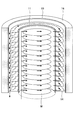
- 1 is a structural diagram of a substrate processing apparatus in a first embodiment.
- 1 is a top structural view of a substrate processing apparatus in a first embodiment. It is explanatory drawing of the gas flow of the substrate processing apparatus in 1st Embodiment. It is an upper surface structure figure of the other substrate processing apparatus in a 1st embodiment.
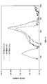
- It is a correlation diagram (1) with the temperature in a substrate processing apparatus, and the amount of generated gas.
- It is a correlation diagram (2) with the temperature in a substrate processing apparatus, and the amount of generated gas.
- It is explanatory drawing (1) of the cleaning method of the substrate processing apparatus in 2nd Embodiment.
- It is explanatory drawing (2) of the cleaning method of the substrate processing apparatus in 2nd Embodiment.
- the substrate processing apparatus using vaporized PMDA, ODA, etc.
- the substrate processing apparatus which can be provided can be provided, and the cleaning method which can remove efficiently the reaction product adhering in this substrate processing apparatus can be provided.
- This embodiment is a substrate processing apparatus, which is a film forming apparatus capable of obtaining polyimide by co-evaporation polymerization using PMDA and ODA as raw material monomers.
- FIG. 1 shows the structure on the side surface of the substrate processing apparatus in the present embodiment
- FIG. 2 shows the structure on the upper surface.
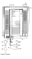
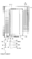
- FIG. 3 shows the flow of an air current such as a gas during the formation of a polyimide film in the substrate processing apparatus according to the embodiment.
- the substrate processing apparatus in the present embodiment has an inner tube (inner tube) 11 in an outer tube (outer tube) 10 corresponding to a chamber, and is formed of quartz together with the outer tube 10 and the inner tube 11. .
- inner tube 11 a plurality of wafers W on which a polyimide film is formed are installed on the wafer boat 12 at a predetermined interval.
- the wafer boat 12 is configured to be rotated by a rotating unit (not shown) so that a polyimide film is uniformly formed on the wafer W.
- a trap portion 13 is provided inside the outer tube 10 and outside the inner tube 11, that is, in a space between the outer tube 10 and the inner tube 11.
- the trap portion 13 is provided with a plurality of disc-shaped fins 14 formed in a circular shape, that is, in a ring shape with a central portion cut out in a circular shape. Are arranged at intervals.
- the fins 14 are formed by processing a quartz substrate or the like, and are formed to have, for example, concentric circular openings. Since the fin 14 is installed outside the inner tube 14 and inside the outer tube 10, the inner diameter of the opening of the fin 14 is larger than the outer diameter of the inner tube 11, The outer diameter of the fin 14 is smaller than the inner diameter of the outer tube 10.
- a heater 16 is provided outside the outer tube 10, and the heater 16 can uniformly heat the wafer W, the outer tube 10, the inner tube 11, the trap portion 13, and the like.
- the heater 16 for example, an infrared heater or the like that is heated by irradiating infrared rays or the like is used.
- an infrared heater or the like when the wafer W, the outer tube 10, the inner tube 11 and the trap portion 13 are made of quartz or the like, infrared rays are transmitted through the quartz, so that the wafer W can be heated uniformly.
- an exhaust port 17 is provided at the bottom of the outer tube 10 inside the outer tube 10 and outside the inner tube 11.
- the exhaust port 17 is connected to the vacuum pump 50 via the monomer trap unit 30 and the valve 40. Therefore, the internal space of the outer tube 10 corresponding to the chamber can be exhausted by the vacuum pump 50 through the exhaust port 17.
- injectors 21 and 22 for supplying vaporized PMDA and ODA are provided. Openings are provided on the side surfaces of the injectors 21 and 22, and PMDA and ODA vaporized from the injectors 21 and 22 are supplied from the horizontal direction to the wafer W as indicated by arrows in the drawing.
- the vaporized PMDA and ODA supplied in this manner causes a vapor deposition polymerization reaction on the wafer W, which is converted to polyimide and deposited on the wafer W.
- FIG. 3 shows the flow of vaporized PMDA and ODA air flow supplied from the injectors 21 and 22 by arrows in the substrate processing apparatus according to the present embodiment.
- the injectors 21 and 22 are connected to the PMDA vaporizer 23 and the ODA vaporizer 24 via the valve unit 25, respectively.
- the valve unit 25 By controlling the valve unit 25, the PMDA vaporized from the PMDA vaporizer 23 and the ODA vaporizer 24 and ODA can be supplied into the inner tube 11 via the injectors 21 and 22.
- a plurality of valves are provided in the valve unit 25, and a gas connected to the valve unit 25 can be selected and flowed.
- the high temperature nitrogen gas is supplied to the PMDA vaporizer 23 as a carrier gas, and the PMDA vaporizer 23 is sublimated to supply the PMDA in a vaporized state. For this reason, the PMDA vaporizer 23 is maintained at a temperature of 260 ° C.
- high-temperature nitrogen gas is supplied as a carrier gas, and the ODA heated to a high temperature and in a liquid state is bubbled with the supplied nitrogen gas, whereby ODA vapor contained in the nitrogen gas is obtained. Supply in a vaporized state. For this reason, the ODA vaporizer 24 is maintained at a temperature of 220 ° C., for example.
- the vaporized PMDA and ODA are supplied to the injectors 21 and 22 through the valve unit 25, and a vapor deposition polymerization reaction occurs on the surface of the wafer W installed in the inner tube 11 to form a polyimide film.
- the heater 16 is heated so that the temperature of the wafer W is maintained at, for example, 200 ° C. (first temperature).
- the first temperature is preferably 180 ° C. or higher and 240 ° C. or lower. This is because the polyimide film starts to be formed when the temperature of the wafer W is 180 ° C. or higher, and no polyimide film is formed when the temperature of the wafer W exceeds 240 ° C.
- the polyimide film is formed in the temperature range of the wafer W between 180 ° C. and 240 ° C. Further, in the substrate processing apparatus in the present embodiment, the oxygen gas supply unit 26 is connected to the valve unit 25 as described later.
- the vaporized PMDA and ODA that did not contribute to the formation of the polyimide film on the surface of the wafer W flow as they are and flow out of the inner tube 11 through the opening 18 provided in the inner tube 11.
- a trap portion 13 provided with the plurality of fins 14 described above is provided inside the outer tube 10 on the outer side of the inner tube 11.
- vaporized PMDA and ODA that have not contributed to the formation of the polyimide film cause a vapor deposition polymerization reaction on the surface of the fin 14 of the trap portion 13, thereby forming a polyimide film.
- the airflow including vaporized PMDA and ODA that has not contributed to the formation of the polyimide film flows along the shape of the fin 14 while forming the polyimide film on the surface of the fin 14 of the trap portion 13.
- the components of vaporized PMDA and ODA in the airflow gradually decrease. That is, in the present embodiment, the vaporized PMDA and ODA that have not contributed to the formation of the polyimide film on the wafer W are vapor-deposited on the surface of the fin 14 of the trap portion 13 and deposited as a polyimide film. Is removed.
- this air stream is discharged from the exhaust port 17 provided in the outer tube 10, but the components of vaporized PMDA and ODA contained in this air stream are sufficiently reduced as described above. Further, thereafter, the airflow discharged from the exhaust port 17 removes PMDA and ODA in the monomer state in the monomer trap unit 30. Thereby, PMDA and ODA can be almost completely removed from the airflow discharged from the exhaust port 17, and then the airflow is exhausted by the vacuum pump 50.
- a polyimide film can be formed on the surface of the wafer W by performing vapor deposition polymerization reaction of PMDA and ODA.
- vaporized PMDA and ODA that did not contribute to the formation of the polyimide film on the surface of the wafer W are vaporized and polymerized and deposited on the surface of the fins 14 of the trap portion 13, thereby being included in the exhausted airflow. Vaporized PMDA and ODA can be removed.
- the fin 14 of the trap portion 13 has been described as being formed of a quartz substrate having a circular opening, that is, a quartz substrate processed into a ring shape. May be made of a material other than a quartz (SiO 2 ) substrate.
- the fins 14 may be formed of a silicon (Si) substrate or a sapphire (Al 2 O 3 ) substrate that is alumina.
- the fin 14 may have other shapes as long as it has a shape capable of efficiently generating and removing a polyimide film by vapor deposition polymerization.
- a plurality of small circular substrates 14 a may be disposed between the inner tube 11 and the outer tube 10.
- an oxygen gas supply unit 26 is connected to the substrate processing apparatus in the present embodiment via a valve unit 25.
- the oxygen gas supply unit 26 is used when cleaning a substrate processing apparatus described later, and supplies oxygen gas into the inner tube 11 via the injectors 21 and 22 by controlling the valve unit 25.
- the PMDA vaporizer 23 and the ODA vaporizer 24 are connected to the injectors 21 and 22 by controlling the valve unit 25. The vaporized PMDA and ODA are supplied into the inner tube 11 through 22.
- the oxygen gas supply unit 26 and the injectors 21 and 22 are connected by controlling the valve unit 25, and the oxygen gas is introduced into the inner tube 11 through the injectors 21 and 22.
- a gas containing is supplied.
- the supplied gas may be pure oxygen gas or oxygen gas diluted with nitrogen gas or the like.
- the fins 14 of the trap portion 13 and the inner tube 11 are formed by vaporized PMDA and ODA that do not contribute to the film formation on the wafer W.
- a polyimide film is also deposited on the inner wall of the outer tube 10 and the inner wall of the outer tube 10. Therefore, it is necessary to perform cleaning for removing the polyimide film deposited on the fins 14 of the trap portion 13, the wall surface of the inner tube 11, the inner wall of the outer tube 10, and the like.
- the fins 14 of the trap portion 13, the wall surface of the inner tube 11, and the outer tube 10 are heated at a predetermined temperature (second temperature) by the heater 16.
- FIG. 5 shows the relationship between the amount of gas generated and the temperature when the outer tube 10 and the inner tube 11 on which polyimide is deposited are heated by the heater 16 in a state where oxygen gas is not introduced.
- FIG. 6 shows the amount of gas generated when the outer tube 10 and the inner tube 11 to which polyimide is attached are heated by the heater 16 in a state where oxygen gas diluted to 20% with nitrogen gas is introduced. The relationship between temperature and temperature is shown.
- the polyimide and oxygen deposited on the outer tube 10 and the inner tube 11 can be efficiently thermochemically reacted, and this thermochemical reaction has occurred.
- the polyimide film deposited on the outer tube 10 and the inner tube 11 can be removed.
- FIG. 7 shows the substrate processing apparatus according to the present embodiment at the time of forming the polyimide film.
- a plurality of wafers W are placed on the wafer boat 21 inside the inner tube 11, and the wafers W, the fins 14, the inner tube 11, and the outer tube 10 are heated to about 200 ° C. by the heater 16.
- vaporized PMDA and ODA are supplied from the injectors 21 and 22 into the inner tube 11, and a polyimide film is formed on the surface of the wafer W.
- the polyimide film is also deposited on the surface of the fin 14 of the trap portion 13, the wall surface of the inner tube 11, the inner surface of the outer tube 10, and the like.
- the wafer W is carried out of the inner tube 11 and out of the outer tube 10.
- the polyimide film remains deposited on the surface of the fin 14 of the trap portion 13, the wall surface of the inner tube 11, the inner surface of the outer tube 10, and the like.
- the fins 14, the inner tube 11 and the outer tube 10 are heated to about 700 ° C. by the heater 16, and as shown in FIG. 9, oxygen gas diluted with nitrogen gas from the injectors 21 and 22 (oxygen gas is 40%). ) Is supplied into the inner tube 11. At this time, oxygen gas diluted with nitrogen gas is supplied so that the pressure inside the outer tube 10 becomes 700 Torr. In this state, the polyimide and oxygen deposited on the surface of the fin 14 of the trap portion 13, the wall surface of the inner tube 11, the inner surface of the outer tube 10 and the like undergo a thermochemical reaction, so that carbon monoxide, carbon dioxide, and water Is generated.
- the carbon monoxide, carbon dioxide, and water thus generated are exhausted from the exhaust port 17 to the outside of the outer tube 10 by the vacuum pump 50.
- the flow of oxygen gas diluted with the supplied nitrogen gas and the generated carbon monoxide, carbon dioxide, and water are indicated by arrows. Since carbon monoxide, carbon dioxide, and water do not adversely affect the vacuum pump 50, even if the generated carbon monoxide, carbon dioxide, and water flow into the vacuum pump 50, the vacuum pump 50 It will not cause any trouble.
- the polyimide film deposited on the surface of the fin 14 of the trap portion 13, the wall surface of the inner tube 11, the inner surface of the outer tube 10 and the like as shown in FIG. 11 can be removed.
- the vacuum pump 50 a root pump, a screw pump, or the like, which is a dry pump, a rotary pump, a scroll pump, or the like is used. This is because these vacuum pumps have a large displacement and are suitable for film formation while flowing a gas such as film formation of a polyimide film. However, these vacuum pumps are likely to cause failure particularly when polyimide or the like is deposited inside, but the substrate processing apparatus according to the present embodiment effectively prevents such vacuum pump failure. It is possible.
- the cleaning described above may be performed for each film forming process, or may be performed after a plurality of film forming processes.
Landscapes
- Chemical & Material Sciences (AREA)
- General Chemical & Material Sciences (AREA)
- Chemical Kinetics & Catalysis (AREA)
- Engineering & Computer Science (AREA)
- Materials Engineering (AREA)
- Mechanical Engineering (AREA)
- Metallurgy (AREA)
- Organic Chemistry (AREA)
- Formation Of Insulating Films (AREA)
- Chemical Vapour Deposition (AREA)
- Drying Of Semiconductors (AREA)
- Physical Vapour Deposition (AREA)
Abstract
真空ポンプにより排気可能なチャンバーとなる外部管と、前記外部管内に設けられ、開口部を有し、内部に基板が設置される内部管と、前記内部管内にガスを導入するためのガス供給部と、前記基板、前記外部管、前記内部管を加熱するためのヒーターと、前記外部管と前記内部管との間の空間に設けられたトラップ部とを備える基板処理装置が開示される。
Description
本発明は、基板処理装置及び基板処理装置のクリーニング方法に関する。
半導体デバイスに用いられる絶縁材料の1つとして、ポリイミドが挙げられる。ポリイミドは密着性が高く、リーク電流も低いことから、層間絶縁膜やパッシベーション膜などに用いられている。このようなポリイミドは半導体デバイスの集積度を上げるため、半導体チップを積層する3次元実装を行う際に、絶縁膜として、特に有望とされている。
このようなポリイミド膜を成膜する方法の一つとして、原料モノマーとして、PMDA(無水ピロメリト酸)とODA(4,4'-オキシジアニリン)を用いた蒸着重合法(共蒸着重合法)による成膜方法が知られている。
この蒸着重合法(Vapor Deposition
Polymerization)は、反応性の高い低分子モノマーであるPMDA及びODAを気化させて、チャンバー内に設置した基板表面に共蒸着し、基板表面で重合させて高分子ポリマーとしてのポリイミドを得る方式である。
具体的に、この蒸着重合反応は下記に示すような反応である。
PMDA+ODA→PAA(ポリアミド酸)→PI(ポリイミド)+H2O
蒸着重合方式による成膜処理を行う基板処理装置においては、基板上での蒸着重合に寄与することのなかった原料モノマーは、ポリイミド膜の成膜に寄与することなくモノマーの状態で排出され、処理装置のチャンバー内を排気するための真空ポンプ内に到達する。このような原料モノマーは、真空ポンプに到達するまでの間に温度が低下し、気体から固体等の状態へと変化し、真空ポンプ内において固着等してしまい真空ポンプの故障の原因となることが知られている。このため、これら原料モノマーが真空ポンプ内に到達する前に除去する必要があり、このような装置としては、水冷コイルを備えたモノマートラップを有する真空重合装置が開示されている(例えば、特許文献1)。
Polymerization)は、反応性の高い低分子モノマーであるPMDA及びODAを気化させて、チャンバー内に設置した基板表面に共蒸着し、基板表面で重合させて高分子ポリマーとしてのポリイミドを得る方式である。
具体的に、この蒸着重合反応は下記に示すような反応である。
PMDA+ODA→PAA(ポリアミド酸)→PI(ポリイミド)+H2O
蒸着重合方式による成膜処理を行う基板処理装置においては、基板上での蒸着重合に寄与することのなかった原料モノマーは、ポリイミド膜の成膜に寄与することなくモノマーの状態で排出され、処理装置のチャンバー内を排気するための真空ポンプ内に到達する。このような原料モノマーは、真空ポンプに到達するまでの間に温度が低下し、気体から固体等の状態へと変化し、真空ポンプ内において固着等してしまい真空ポンプの故障の原因となることが知られている。このため、これら原料モノマーが真空ポンプ内に到達する前に除去する必要があり、このような装置としては、水冷コイルを備えたモノマートラップを有する真空重合装置が開示されている(例えば、特許文献1)。
また、原料にポリマーの気化物質を使用しない、通常の真空成膜装置では、排気中の未反応成分が真空ポンプに異物として混入しないように、チャンバーと真空ポンプの間に除去装置が設けられている。このような除去装置の一種として、除去装置内で未反応成分を反応させて内壁に付着させることにより、未反応成分を除去する除去装置が開示されている(例えば、特許文献2)。
一方、蒸着重合方式による成膜処理を行う基板処理装置においては、基板上での蒸着重合に寄与することのなかった原料モノマーが、基板処理装置のチャンバー内等においてポリマーとしてポリイミド膜を形成してしまう。このようなポリイミド膜を除去する方法として、チャンバー等を850℃以上の高温にすることにより分解して除去する方法が開示されている(例えば、特許文献3)。
本発明は、気化したPMDAやODA等を用いる基板処理装置において、基板上における成膜に寄与しなかった、気化したPMDAやODA等を反応させることにより効率的に除去することができる基板処理装置を提供するとともに、この基板処理装置内に付着している反応生成物を効率的に除去することのできるクリーニング方法を提供する。
本発明の第1の態様によれば、真空ポンプにより排気可能なチャンバーとなる外部管と、 前記外部管内に設けられ、内部に基板が設置される内部管であって、当該内部管及び前記外部管の間の空間と前記内部管の内部空間とを連通する開口部を有する当該内部管と、互いに重合反応し得る少なくとも2種類のガスを前記内部管内に導入するためのガス供給部と、前記基板、前記外部管、及び前記内部管を加熱するためのヒーターと、前記外部管と前記内部管との間の空間に設けられ、前記開口部から前記空間へ流入した、前記内部管内で未反応の前記ガスが重合反応により堆積し得るトラップ部とを備える基板処理装置が提供される。
また、本発明の第2の態様によれば、真空ポンプにより排気可能なチャンバーとなる外部管と、前記外部管内に設けられ、内部に基板が設置される内部管であって、当該内部管及び前記外部管の間の空間と前記内部管の内部空間とを連通する開口部を有する当該内部管と、前記内部管内にガスを導入するためのガス供給部と、前記基板、前記外部管、及び前記内部管を加熱するためのヒーターと、前記外部管と前記内部管との間の空間に設けられたトラップ部と、を備える基板処理装置において、前記ヒーターにより前記基板を第1の温度に加熱し、蒸着重合反応を起こすガスを前記ガス供給部から供給することにより、前記蒸着重合反応によりに生成された膜を前記基板の表面に成膜し、前記内部管の前記開口部から前記空間に流入した前記ガスにより、前記トラップ部においても、前記蒸着重合反応により生成された膜を成膜した後に前記基板処理装置をクリーニングするクリーニング方法が提供される。このクリーニング方法は、前記蒸着重合反応により生成された膜が成膜された前記基板を内部管から搬出する工程と、前記ヒーターにより、前記トラップ部を前記第1の温度よりも高い第2の温度に加熱する工程と、前記ガス供給部より酸素ガスを含むガスを供給する工程と、を含む。
本発明の実施形態によれば、気化したPMDAやODA等を用いる基板処理装置において、基板上において成膜に寄与しなかった気化したPMDAやODA等を反応させることにより効率的に除去することができる基板処理装置を提供することができ、また、この基板処理装置内に付着している反応生成物を効率的に除去することのできるクリーニング方法を提供することができる。以下、本発明の一実施の形態について、詳細に説明する。
〔第1の実施の形態〕
本実施の形態は基板処理装置であり、原料モノマーとしてPMDAとODAを用いて、共蒸着重合によりポリイミドを得ることのできる成膜装置である。
本実施の形態は基板処理装置であり、原料モノマーとしてPMDAとODAを用いて、共蒸着重合によりポリイミドを得ることのできる成膜装置である。
図1から図3に基づき、本実施の形態における基板処理装置である成膜装置について説明する。尚、図1は、本実施の形態における基板処理装置の側面における構造を示し、図2は、上面における構造を示す。また、図3は、実施の形態における基板処理装置において、ポリイミド膜の成膜の際におけるガス等の気流の流れを示す。
本実施の形態における基板処理装置は、チャンバーに相当するアウターチューブ(外部管)10内にインナーチューブ(内部管)11を有しており、アウターチューブ10及びインナーチューブ11とともに石英により形成されている。インナーチューブ11内には、ポリイミド膜が成膜される複数のウエハWが、ウエハボート12に所定の間隔で設置されている。尚、ウエハボート12はウエハW上に均一にポリイミド膜が成膜されるように、不図示の回転部により回転することができるように構成されている。
また、アウターチューブ10内側であってインナーチューブ11の外側、即ち、アウターチューブ10とインナーチューブ11の間の空間には、トラップ部13が設けられている。トラップ部13は、中心部が円形にくり抜かれた円板状、即ち、リング状に形成された円板状の複数のフィン14が設けられており、これら複数のフィン14は支柱部15により所定の間隔を隔て配置されている。本実施の形態においては、フィン14は、石英基板等を加工することにより形成されており、例えば、同心円状の円形の開口を有するように形成されている。尚、このフィン14は、インナーチューブ14の外側であって、アウターチューブの10の内側に設置されるものであるため、フィン14の開口部の内径は、インナーチューブ11の外径よりも大きく、フィン14の外径は、アウターチューブ10の内径よりも小さい。
また、アウターチューブ10の外側にはヒーター16が設けられており、このヒーター16により、ウエハW、アウターチューブ10、インナーチューブ11、及びトラップ部13等を均一に加熱することが可能である。ヒーター16は、例えば、赤外線等を照射することにより加熱する、例えば、赤外線ヒーター等が用いられる。赤外線ヒーター等では、ウエハW、アウターチューブ10、インナーチューブ11及びトラップ部13が石英等で形成されている場合、赤外線は石英を透過するため、ウエハWを均一に加熱することができ好ましい。
また、アウターチューブ10の底部において、アウターチューブ10内側であって、インナーチューブ11の外側には排気口17が設けられている。排気口17は、モノマートラップ部30、バルブ40を介し、真空ポンプ50と接続されている。従って、チャンバーに相当するアウターチューブ10の内部空間は、排気口17を介し真空ポンプ50により排気することができる。
また、インナーチューブ11内には、気化したPMDA及びODAを供給するためのインジェクター21及び22が設けられている。このインジェクター21及び22の側面には開口部が設けられており、インジェクター21及び22より気化したPMDA及びODAが図面において矢印で示すようにウエハWに対して水平方向から供給される。このようにして供給された気化したPMDA及びODAにより、ウエハW上で蒸着重合反応が生じ、ポリイミドとなってウエハWに析出する。尚、図3は、本実施の形態における基板処理装置において、インジェクター21及び22より供給される気化したPMDA及びODAの気流の流れを矢印にて示している。
インジェクター21及び22は、PMDA気化器23及びODA気化器24とバルブ部25を介しそれぞれ接続されており、バルブ部25を制御することにより、PMDA気化器23及びODA気化器24より気化したPMDA及びODAをインジェクター21及び22を介しインナーチューブ11内に供給することができる。尚、バルブ部25内には、複数のバルブが設けられており、バルブ部25に接続されているガスを選択して流すことが可能である。
PMDA気化器23には高温の窒素ガスをキャリアガスとして供給し、PMDA気化器23においてPMDAを昇華させることにより、気化した状態で供給する。このため、PMDA気化器23は、260℃の温度に保たれている。また、ODA気化器24では、高温の窒素ガスをキャリアガスとして供給し、高温に加熱され液体状態となったODAを供給された窒素ガスによりバブリングすることにより、窒素ガスに含まれるODAの蒸気とし、気化した状態で供給する。このため、ODA気化器24は例えば220℃の温度に保たれている。この後、気化したPMDA及びODAは、バルブ部25を介してインジェクター21及び22に供給され、インナーチューブ11内に設置されたウエハWの表面において蒸着重合反応が生じポリイミド膜が成膜される。尚、ウエハW上にポリイミド膜を成膜する際には、ヒーター16によりウエハWの温度が例えば200℃(第1の温度)に保たれるように加熱されている。ここで、第1の温度は、180℃以上、240℃以下であることが好ましい。ポリイミド膜はウエハWの温度が180℃以上で成膜されはじめ、ウエハWの温度が240℃を超えるとポリイミド膜が成膜されなくなるからである。即ち、本実施の形態では、ウエハWの温度が180℃以上、240℃以下の温度範囲においてポリイミド膜が成膜される。また、本実施の形態における基板処理装置においては、後述するように酸素ガス供給部26がバルブ部25に接続されている。
ここで、ウエハWの表面においてポリイミド膜の成膜に寄与しなかった気化したPMDA及びODAは、そのまま流れ、インナーチューブ11に設けられた開口部18よりインナーチューブ11の外に流出する。インナーチューブ11の外側であって、アウターチューブ10の内側には、上述した複数のフィン14が設けられたトラップ部13が設けられている。このため、ポリイミド膜の成膜に寄与しなかった気化したPMDA及びODAにより、トラップ部13のフィン14の表面において蒸着重合反応が生じ、ポリイミド膜が成膜される。このようにして、ポリイミド膜の成膜に寄与しなかった気化したPMDA及びODAを含む気流は、トラップ部13のフィン14の表面にポリイミド膜を成膜しながらフィン14の形状に沿って流れる。このようにフィン14の表面にポリイミド膜が成膜されることにより、気流内における気化したPMDA及びODAの成分は次第に減少していく。即ち、本実施の形態においては、ウエハW上でポリイミド膜の成膜に寄与しなかった気化したPMDA及びODAは、トラップ部13のフィン14の表面で互いに蒸着重合反応し、ポリイミド膜として堆積することにより、除去される。
この後、この気流はアウターチューブ10に設けられた排気口17より排出されるが、この気流に含まれる気化したPMDA及びODAの成分は、上述のように十分に低減されている。さらに、この後、排気口17より排出された気流は、モノマートラップ部30において、PMDA及びODAをモノマーの状態で除去する。これにより、排気口17より排出された気流から、ほぼ完全にPMDA及びODAを除去することができ、その後、この気流は真空ポンプ50により排気される。
このように、本実施の形態における基板処理装置では、PMDA及びODAを蒸着重合反応させることによりウエハWの表面にポリイミド膜を成膜することができる。この際、ウエハWの表面においてポリイミド膜の成膜に寄与しなかった気化したPMDA及びODAを蒸着重合反応させ、トラップ部13のフィン14の表面に堆積させることにより、排気される気流に含まれる気化したPMDA及びODAを除去することができる。
これにより真空ポンプ50内に、PMDA及びODAが入り込むことを防ぐことができ、真空ポンプ50の故障を防ぐことができる。
尚、本実施の形態では、トラップ部13のフィン14は円形の開口部を有する石英基板、即ち、リング状に加工された石英基板により構成したものについて説明したが、フィン14を構成する基板材料は、石英(SiO2)基板以外の材料により構成してもよい。例えば、シリコン(Si)基板やアルミナであるサファイア(Al2O3)基板等によりフィン14を構成してもよい。
また、フィン14は、効率よく蒸着重合によりポリイミド膜を生成し除去することが可能な形状を有している限り、他の形状を有してもよい。例えば、図4に示すように、小型の複数の円形基板14aをインナーチューブ11とアウターチューブ10の間に配置してもよい。
さらに、本実施の形態における基板処理装置には、バルブ部25を介し酸素ガス供給部26が接続されている。この酸素ガス供給部26は、後述する基板処理装置のクリーニングを行う際に用いるものであり、バルブ部25を制御することにより、インジェクター21及び22を介しインナーチューブ11内に酸素ガスを供給する。具体的には、ウエハWの表面にポリイミド膜を成膜する際には、バルブ部25を制御することにより、PMDA気化器23及びODA気化器24とインジェクター21及び22を接続し、インジェクター21及び22を介しインナーチューブ11内に気化したPMDA及びODAを供給する。一方、基板処理装置のクリーニングを行う際には、バルブ部25を制御することにより、酸素ガス供給部26とインジェクター21及び22とを接続し、インジェクター21及び22を介しインナーチューブ11内に酸素ガスを含むガスを供給する。尚、この場合供給されるガスは、純酸素ガスであってもよく、また、窒素ガス等により希釈された酸素ガスであってもよい。
〔第2の実施の形態〕
次に、第1の実施の形態となる基板処理装置を用いた基板処理装置のクリーニング方法について説明する。
次に、第1の実施の形態となる基板処理装置を用いた基板処理装置のクリーニング方法について説明する。
第1の実施の形態における基板処理装置において、ウエハWにポリイミド膜を成膜する場合、ウエハWへの成膜に寄与しない、気化したPMDA及びODAにより、トラップ部13のフィン14、インナーチューブ11の壁面、アウターチューブ10の内壁等にもポリイミド膜が堆積される。このため、トラップ部13のフィン14、インナーチューブ11の壁面、アウターチューブ10の内壁等に堆積しているポリイミド膜を除去するためのクリーニングを行う必要がある。具体的には、第1の実施の形態における基板処理装置において、トラップ部13のフィン14、インナーチューブ11の壁面、及びアウターチューブ10を、ヒーター16により所定の温度(第2の温度)で加熱し、インナーチューブ11内に酸素ガスを供給することにより、トラップ部13のフィン14、インナーチューブ11の壁面、及びアウターチューブ10の内壁に付着しているポリイミドと酸素とを熱化学反応させて、一酸化炭素(CO)、二酸化炭素(CO2)、水(H2O)に分解し除去する。
このことを図5及び図6に基づき説明する。図5は酸素ガスを導入しない状態において、ヒーター16によりポリイミドが堆積しているアウターチューブ10及びインナーチューブ11等を加熱した場合に発生するガスの発生量と温度との関係を示す。また、図6は窒素ガスにより20%に希釈された酸素ガスを導入した状態において、ヒーター16によりポリイミドが付着しているアウターチューブ10及びインナーチューブ11等を加熱した場合に発生するガスの発生量と温度との関係を示す。
図6に示されるように、酸素ガスを導入し、ポリイミドが堆積しているアウターチューブ10及びインナーチューブ11等を加熱することにより、ポリイミドと酸素の反応生成物である一酸化炭素(分子量:28)、二酸化炭素(分子量:44)、水(分子量:18)の発生量が増加している。また、図5に示されるように、酸素ガス等が導入されていない状態で加熱した場合では、ポリイミドの熱分解により発生する分子量が93及び94であるアニリン及びフェノール等の有機材料の発生が確認される。一方、図6に示されるように、酸素ガスを導入し、加熱した場合では、分子量が93及び94であるアニリン及びフェノール等の有機材料の発生は確認されなかった。
以上より、酸素ガスを導入し、加熱することにより、アウターチューブ10及びインナーチューブ11等に堆積しているポリイミドと酸素とを効率的に熱化学反応させることができ、この熱化学反応により生じた一酸化炭素、二酸化炭素及び水を除去することにより、アウターチューブ10及びインナーチューブ11等に堆積しているポリイミド膜を除去することができる。
また、図6に示されるように、蒸着重合によりポリイミド膜が成膜される温度(第1の温度)である200℃よりも高い、400℃から800℃の範囲において、一酸化炭素、二酸化炭素、水が発生しており、その発生量は、特に550℃から700℃の範囲において顕著に増加している。このため、酸素ガスを流しながらクリーニングを行う際には、ヒーター16によりアウターチューブ10、インナーチューブ11及びトラップ部13等を400℃から800℃に加熱した状態で行うことが好ましく、更に好ましくは、550℃から700℃に加熱して行うことが好ましい。
次に、図7から図11に基づき、本実施の形態における基板処理装置において行われるポリイミド膜の成膜からクリーニングについて説明する。
図7は、ポリイミド膜の成膜時における、本実施の形態による基板処理装置を示している。成膜時には、インナーチューブ11内部のウエハボート21に複数のウエハWが設置されており、ウエハW、フィン14、インナーチューブ11、及びアウターチューブ10はヒーター16により約200℃に加熱されている。この後、インジェクター21及び22から、気化したPMDA及びODAをインナーチューブ11内部に供給し、ウエハWの表面にポリイミド膜を成膜する。この際、トラップ部13のフィン14の表面、インナーチューブ11の壁面及びアウターチューブ10の内面等にもポリイミド膜が堆積される。
次に、図8に示すように、ウエハWの表面に所定の膜厚のポリイミド膜を成膜した後、ウエハWはインナーチューブ11内よりアウターチューブ10の外に搬出する。尚、このときには、トラップ部13のフィン14の表面、インナーチューブ11の壁面、及びアウターチューブ10の内面等においてポリイミド膜が堆積されたままである。
次に、ヒーター16によりフィン14、インナーチューブ11及びアウターチューブ10を約700℃に加熱し、図9に示すように、インジェクター21及び22より窒素ガスにより希釈された酸素ガス(酸素ガスが40%)をインナーチューブ11内部に供給する。この際、アウターチューブ10の内部における圧力が、700Torrとなるように窒素ガスにより希釈された酸素ガスを供給する。この状態では、トラップ部13のフィン14の表面、インナーチューブ11の壁面、及びアウターチューブ10の内面等に堆積されているポリイミドと酸素とが熱化学反応し、一酸化炭素、二酸化炭素、及び水が生成される。このように生成された一酸化炭素、二酸化炭素、及び水は、排気口17からアウターチューブ10の外に真空ポンプ50により排気される。図10には、供給される窒素ガスにより希釈された酸素ガス及び生成された一酸化炭素、二酸化炭素、及び水の流れを矢印により示す。尚、一酸化炭素、二酸化炭素、及び水は真空ポンプ50に悪影響を与えることはないため、真空ポンプ50内に、生成された一酸化炭素、二酸化炭素、水が流れ込んだとしても、真空ポンプ50の故障の原因等になることはない。
このようにして、図11に示すようにトラップ部13のフィン14の表面、インナーチューブ11の壁面及びアウターチューブ10の内面等に堆積されていたポリイミド膜を除去することができる。
尚、本実施の形態における基板処理装置においては、真空ポンプ50としては、ドライポンプであるルーツポンプ、スクリューポンプ等、また、ロータリーポンプ、スクロールポンプ等が用いられている。これらの真空ポンプは、排気量が大きくポリイミド膜を成膜等のようにガスを流しながらの成膜に適しているからである。しかしながら、これらの真空ポンプは、内部にポリイミド等が析出した場合には、特に故障の原因となりやすいが、本実施の形態における基板処理装置においては、このような真空ポンプの故障を効果的に防ぐことが可能である。
また、上記のクリーニングは、成膜プロセス毎に行っても良いし、複数回の成膜プロセスの後に行っても良い。
以上、幾つかの実施の形態を参照しながら本発明を説明したが、本発明は上述の実施の形態に限定されることなく、添付の請求の範囲に照らし種々に変形又は変更をすることができる。
本国際出願は2010年6月29日に出願された日本国特許出願2010-148012号に基づく優先権を主張するものであり、その全内容をここに援用する。
Claims (14)
- 真空ポンプにより排気可能なチャンバーとなる外部管と、
前記外部管内に設けられ、内部に基板が設置される内部管であって、当該内部管及び前記外部管の間の空間と前記内部管の内部空間とを連通する開口部を有する当該内部管と、
互いに重合反応し得る少なくとも2種類のガスを前記内部管内に導入するためのガス供給部と、
前記基板、前記外部管、及び前記内部管を加熱するためのヒーターと、
前記外部管と前記内部管との間の空間に設けられ、前記開口部から前記空間へ流入した、前記内部管内で未反応の前記ガスが重合反応により堆積し得るトラップ部と
を備える基板処理装置。 - 前記外部管及び前記内部管が石英で形成されている、請求項1に記載の基板処理装置。
- 前記ヒーターが赤外線ヒーターである、請求項2に記載の基板処理装置。
- 前記トラップ部が、所定の間隔で配置される複数の板部材を備え、前記複数の板部材が石英、シリコン、及びアルミナのいずれかにより形成される、請求項1に記載の基板処理装置。
- 前記複数の板部材の各々が、前記内部管の外径よりも大きな内径の開口部を有している、請求項4に記載の基板処理装置。
- 前記ヒーターにより前記基板が180℃以上240℃以下の温度に加熱される、請求項1に記載の基板処理装置。
- 前記ガスがPMDA及びODAを含む、請求項1に記載の基板処理装置。
- 前記ガス供給部に酸素を含むガスを導入する酸素ガス供給部と、
前記ガスと前記酸素を含むガスとを切り換えて導入するためのバルブ部と
を更に備える、請求項1に記載の基板処理装置。 - 真空ポンプにより排気可能なチャンバーとなる外部管と、
前記外部管内に設けられ、内部に基板が設置される内部管であって、当該内部管及び前記外部管の間の空間と前記内部管の内部空間とを連通する開口部を有する当該内部管と、
前記内部管内にガスを導入するためのガス供給部と、
前記基板、前記外部管、及び前記内部管を加熱するためのヒーターと、
前記外部管と前記内部管との間の空間に設けられたトラップ部と、を備える基板処理装置において、
前記ヒーターにより前記基板を第1の温度に加熱し、
互いに重合反応し得る少なくとも2種類のガスを前記ガス供給部から前記内部管に供給することにより、前記基板の表面に膜を成膜し、
前記内部管の前記開口部から前記空間に流入した、前記内部管において未反応の前記ガスにより、前記トラップ部に膜を堆積した後に前記基板処理装置をクリーニングするクリーニング方法であって、
重合反応により生成された膜が成膜された前記基板を前記内部管から搬出する工程と、
前記ヒーターにより、前記トラップ部を前記第1の温度よりも高い第2の温度に加熱する工程と、
前記ガス供給部より酸素ガスを含むガスを供給する工程と、
を含む、基板処理装置のクリーニング方法。 - 前記外部管及び前記内部管が石英で形成されている、請求項9に記載のクリーニング方法。
- 前記ヒーターが赤外線ヒーターである、請求項10に記載のクリーニング方法。
- 前記トラップ部が、所定の間隔で配置される複数の板部材を備え、前記複数の板部材が石英、シリコン、及びアルミナのいずれかにより形成される、請求項9に記載のクリーニング方法。
- 前記ガスがPMDA及びODAを含む、請求項9に記載のクリーニング方法。
- 前記第1の温度が、180℃以上240℃以下の範囲にあり、前記第2の温度が、400℃以上800℃以下の範囲にある、請求項9に記載のクリーニング方法。
Applications Claiming Priority (2)
| Application Number | Priority Date | Filing Date | Title |
|---|---|---|---|
| JP2010148012A JP5534979B2 (ja) | 2010-06-29 | 2010-06-29 | 基板処理装置及び基板処理装置のクリーニング方法 |
| JP2010-148012 | 2010-06-29 |
Publications (1)
| Publication Number | Publication Date |
|---|---|
| WO2012002159A1 true WO2012002159A1 (ja) | 2012-01-05 |
Family
ID=45401884
Family Applications (1)
| Application Number | Title | Priority Date | Filing Date |
|---|---|---|---|
| PCT/JP2011/063812 Ceased WO2012002159A1 (ja) | 2010-06-29 | 2011-06-16 | 基板処理装置及び基板処理装置のクリーニング方法 |
Country Status (2)
| Country | Link |
|---|---|
| JP (1) | JP5534979B2 (ja) |
| WO (1) | WO2012002159A1 (ja) |
Families Citing this family (5)
| Publication number | Priority date | Publication date | Assignee | Title |
|---|---|---|---|---|
| JP6020239B2 (ja) | 2012-04-27 | 2016-11-02 | 東京エレクトロン株式会社 | 成膜方法及び成膜装置 |
| JP6254459B2 (ja) | 2014-02-27 | 2017-12-27 | 東京エレクトロン株式会社 | 重合膜の耐薬品性改善方法、重合膜の成膜方法、成膜装置、および電子製品の製造方法 |
| US10883175B2 (en) * | 2018-08-09 | 2021-01-05 | Asm Ip Holding B.V. | Vertical furnace for processing substrates and a liner for use therein |
| JP7240557B2 (ja) * | 2020-03-24 | 2023-03-15 | 株式会社Kokusai Electric | 基板処理装置、半導体装置の製造方法、プログラムおよびインナーチューブ |
| JP7399260B2 (ja) * | 2020-03-25 | 2023-12-15 | 株式会社Kokusai Electric | 基板処理装置、基板処理方法、半導体装置の製造方法、プログラム、およびインナーチューブ |
Citations (4)
| Publication number | Priority date | Publication date | Assignee | Title |
|---|---|---|---|---|
| JPH05160029A (ja) * | 1991-12-02 | 1993-06-25 | Hitachi Ltd | 成膜装置およびその排気トラップ |
| JPH10189465A (ja) * | 1996-12-26 | 1998-07-21 | Dainippon Screen Mfg Co Ltd | 基板の熱処理装置およびそれを備える薄膜形成装置 |
| JP2001308082A (ja) * | 2000-04-20 | 2001-11-02 | Nec Corp | 液体有機原料の気化方法及び絶縁膜の成長方法 |
| JP2009194099A (ja) * | 2008-02-13 | 2009-08-27 | Tokyo Electron Ltd | 成膜装置及び成膜方法 |
-
2010
- 2010-06-29 JP JP2010148012A patent/JP5534979B2/ja active Active
-
2011
- 2011-06-16 WO PCT/JP2011/063812 patent/WO2012002159A1/ja not_active Ceased
Patent Citations (4)
| Publication number | Priority date | Publication date | Assignee | Title |
|---|---|---|---|---|
| JPH05160029A (ja) * | 1991-12-02 | 1993-06-25 | Hitachi Ltd | 成膜装置およびその排気トラップ |
| JPH10189465A (ja) * | 1996-12-26 | 1998-07-21 | Dainippon Screen Mfg Co Ltd | 基板の熱処理装置およびそれを備える薄膜形成装置 |
| JP2001308082A (ja) * | 2000-04-20 | 2001-11-02 | Nec Corp | 液体有機原料の気化方法及び絶縁膜の成長方法 |
| JP2009194099A (ja) * | 2008-02-13 | 2009-08-27 | Tokyo Electron Ltd | 成膜装置及び成膜方法 |
Also Published As
| Publication number | Publication date |
|---|---|
| JP2012015195A (ja) | 2012-01-19 |
| JP5534979B2 (ja) | 2014-07-02 |
Similar Documents
| Publication | Publication Date | Title |
|---|---|---|
| US9139933B2 (en) | Semiconductor substrate manufacturing apparatus | |
| CN100350574C (zh) | 在被处理基板上形成硅氮化膜的cvd方法 | |
| US7387968B2 (en) | Batch photoresist dry strip and ash system and process | |
| TWI415188B (zh) | 半導體製程用之捕集單元 | |
| KR101126536B1 (ko) | 플라즈마 처리 시스템 및 플라즈마 처리 방법 | |
| JP5534979B2 (ja) | 基板処理装置及び基板処理装置のクリーニング方法 | |
| JP5542560B2 (ja) | 半導体製造装置およびサセプタのクリーニング方法 | |
| TW201926481A (zh) | 半導體裝置之製造方法及基板處理裝置 | |
| JP5281146B2 (ja) | 基板処理装置、トラップ装置、基板処理装置の制御方法及びトラップ装置の制御方法 | |
| JP6453637B2 (ja) | クリーニング方法、半導体装置の製造方法、基板処理装置およびプログラム | |
| EP3854492B1 (en) | Apparatus for cleaning component of semiconductor production apparatus, method for cleaning component of semiconductor production apparatus, and system for cleaning component of semiconductor production apparatus | |
| US12525447B2 (en) | Systems and methods for depositing low-k dielectric films | |
| JP3153190B2 (ja) | 高分子膜の製造装置とこの装置を用いた成膜方法 | |
| JP2010056565A (ja) | 薄膜製造装置 | |
| US20130008381A1 (en) | Trap apparatus and substrate processing apparatus | |
| US20180076030A1 (en) | SiC FILM FORMING METHOD AND SiC FILM FORMING APPARATUS | |
| TW200902746A (en) | Inductively heated trap | |
| JP2005054252A (ja) | 薄膜製造装置及び製造方法 | |
| TWI794882B (zh) | 電漿沉積的膜中之氫管控 | |
| JP4283911B2 (ja) | 半導体製造装置およびポリイミド膜の形成方法 | |
| JP7428528B2 (ja) | エッチング方法 | |
| JP4620288B2 (ja) | バッチ式熱処理装置 | |
| JP2001230244A (ja) | 絶縁膜の形成方法および多層配線 | |
| CN121545982A (zh) | 半导体设备及工艺腔体维护方法 | |
| TW202526071A (zh) | 用於形成具有減低介電常數及增加密度的低k介電材料之方法 |
Legal Events
| Date | Code | Title | Description |
|---|---|---|---|
| 121 | Ep: the epo has been informed by wipo that ep was designated in this application |
Ref document number: 11800625 Country of ref document: EP Kind code of ref document: A1 |
|
| NENP | Non-entry into the national phase |
Ref country code: DE |
|
| 122 | Ep: pct application non-entry in european phase |
Ref document number: 11800625 Country of ref document: EP Kind code of ref document: A1 |