WO2011155015A1 - Hybrid vehicle and method of controlling thereof - Google Patents
Hybrid vehicle and method of controlling thereof Download PDFInfo
- Publication number
- WO2011155015A1 WO2011155015A1 PCT/JP2010/059615 JP2010059615W WO2011155015A1 WO 2011155015 A1 WO2011155015 A1 WO 2011155015A1 JP 2010059615 W JP2010059615 W JP 2010059615W WO 2011155015 A1 WO2011155015 A1 WO 2011155015A1
- Authority
- WO
- WIPO (PCT)
- Prior art keywords
- torque
- damping
- output
- electric motor
- motor
- Prior art date
Links
Images


Classifications
-
- B—PERFORMING OPERATIONS; TRANSPORTING
- B60—VEHICLES IN GENERAL
- B60K—ARRANGEMENT OR MOUNTING OF PROPULSION UNITS OR OF TRANSMISSIONS IN VEHICLES; ARRANGEMENT OR MOUNTING OF PLURAL DIVERSE PRIME-MOVERS IN VEHICLES; AUXILIARY DRIVES FOR VEHICLES; INSTRUMENTATION OR DASHBOARDS FOR VEHICLES; ARRANGEMENTS IN CONNECTION WITH COOLING, AIR INTAKE, GAS EXHAUST OR FUEL SUPPLY OF PROPULSION UNITS IN VEHICLES
- B60K6/00—Arrangement or mounting of plural diverse prime-movers for mutual or common propulsion, e.g. hybrid propulsion systems comprising electric motors and internal combustion engines ; Control systems therefor, i.e. systems controlling two or more prime movers, or controlling one of these prime movers and any of the transmission, drive or drive units Informative references: mechanical gearings with secondary electric drive F16H3/72; arrangements for handling mechanical energy structurally associated with the dynamo-electric machine H02K7/00; machines comprising structurally interrelated motor and generator parts H02K51/00; dynamo-electric machines not otherwise provided for in H02K see H02K99/00
- B60K6/20—Arrangement or mounting of plural diverse prime-movers for mutual or common propulsion, e.g. hybrid propulsion systems comprising electric motors and internal combustion engines ; Control systems therefor, i.e. systems controlling two or more prime movers, or controlling one of these prime movers and any of the transmission, drive or drive units Informative references: mechanical gearings with secondary electric drive F16H3/72; arrangements for handling mechanical energy structurally associated with the dynamo-electric machine H02K7/00; machines comprising structurally interrelated motor and generator parts H02K51/00; dynamo-electric machines not otherwise provided for in H02K see H02K99/00 the prime-movers consisting of electric motors and internal combustion engines, e.g. HEVs
- B60K6/22—Arrangement or mounting of plural diverse prime-movers for mutual or common propulsion, e.g. hybrid propulsion systems comprising electric motors and internal combustion engines ; Control systems therefor, i.e. systems controlling two or more prime movers, or controlling one of these prime movers and any of the transmission, drive or drive units Informative references: mechanical gearings with secondary electric drive F16H3/72; arrangements for handling mechanical energy structurally associated with the dynamo-electric machine H02K7/00; machines comprising structurally interrelated motor and generator parts H02K51/00; dynamo-electric machines not otherwise provided for in H02K see H02K99/00 the prime-movers consisting of electric motors and internal combustion engines, e.g. HEVs characterised by apparatus, components or means specially adapted for HEVs
- B60K6/36—Arrangement or mounting of plural diverse prime-movers for mutual or common propulsion, e.g. hybrid propulsion systems comprising electric motors and internal combustion engines ; Control systems therefor, i.e. systems controlling two or more prime movers, or controlling one of these prime movers and any of the transmission, drive or drive units Informative references: mechanical gearings with secondary electric drive F16H3/72; arrangements for handling mechanical energy structurally associated with the dynamo-electric machine H02K7/00; machines comprising structurally interrelated motor and generator parts H02K51/00; dynamo-electric machines not otherwise provided for in H02K see H02K99/00 the prime-movers consisting of electric motors and internal combustion engines, e.g. HEVs characterised by apparatus, components or means specially adapted for HEVs characterised by the transmission gearings
- B60K6/365—Arrangement or mounting of plural diverse prime-movers for mutual or common propulsion, e.g. hybrid propulsion systems comprising electric motors and internal combustion engines ; Control systems therefor, i.e. systems controlling two or more prime movers, or controlling one of these prime movers and any of the transmission, drive or drive units Informative references: mechanical gearings with secondary electric drive F16H3/72; arrangements for handling mechanical energy structurally associated with the dynamo-electric machine H02K7/00; machines comprising structurally interrelated motor and generator parts H02K51/00; dynamo-electric machines not otherwise provided for in H02K see H02K99/00 the prime-movers consisting of electric motors and internal combustion engines, e.g. HEVs characterised by apparatus, components or means specially adapted for HEVs characterised by the transmission gearings with the gears having orbital motion
-
- B—PERFORMING OPERATIONS; TRANSPORTING
- B60—VEHICLES IN GENERAL
- B60W—CONJOINT CONTROL OF VEHICLE SUB-UNITS OF DIFFERENT TYPE OR DIFFERENT FUNCTION; CONTROL SYSTEMS SPECIALLY ADAPTED FOR HYBRID VEHICLES; ROAD VEHICLE DRIVE CONTROL SYSTEMS FOR PURPOSES NOT RELATED TO THE CONTROL OF A PARTICULAR SUB-UNIT
- B60W20/00—Control systems specially adapted for hybrid vehicles
- B60W20/10—Controlling the power contribution of each of the prime movers to meet required power demand
- B60W20/15—Control strategies specially adapted for achieving a particular effect
-
- B—PERFORMING OPERATIONS; TRANSPORTING
- B60—VEHICLES IN GENERAL
- B60K—ARRANGEMENT OR MOUNTING OF PROPULSION UNITS OR OF TRANSMISSIONS IN VEHICLES; ARRANGEMENT OR MOUNTING OF PLURAL DIVERSE PRIME-MOVERS IN VEHICLES; AUXILIARY DRIVES FOR VEHICLES; INSTRUMENTATION OR DASHBOARDS FOR VEHICLES; ARRANGEMENTS IN CONNECTION WITH COOLING, AIR INTAKE, GAS EXHAUST OR FUEL SUPPLY OF PROPULSION UNITS IN VEHICLES
- B60K6/00—Arrangement or mounting of plural diverse prime-movers for mutual or common propulsion, e.g. hybrid propulsion systems comprising electric motors and internal combustion engines ; Control systems therefor, i.e. systems controlling two or more prime movers, or controlling one of these prime movers and any of the transmission, drive or drive units Informative references: mechanical gearings with secondary electric drive F16H3/72; arrangements for handling mechanical energy structurally associated with the dynamo-electric machine H02K7/00; machines comprising structurally interrelated motor and generator parts H02K51/00; dynamo-electric machines not otherwise provided for in H02K see H02K99/00
- B60K6/20—Arrangement or mounting of plural diverse prime-movers for mutual or common propulsion, e.g. hybrid propulsion systems comprising electric motors and internal combustion engines ; Control systems therefor, i.e. systems controlling two or more prime movers, or controlling one of these prime movers and any of the transmission, drive or drive units Informative references: mechanical gearings with secondary electric drive F16H3/72; arrangements for handling mechanical energy structurally associated with the dynamo-electric machine H02K7/00; machines comprising structurally interrelated motor and generator parts H02K51/00; dynamo-electric machines not otherwise provided for in H02K see H02K99/00 the prime-movers consisting of electric motors and internal combustion engines, e.g. HEVs
- B60K6/42—Arrangement or mounting of plural diverse prime-movers for mutual or common propulsion, e.g. hybrid propulsion systems comprising electric motors and internal combustion engines ; Control systems therefor, i.e. systems controlling two or more prime movers, or controlling one of these prime movers and any of the transmission, drive or drive units Informative references: mechanical gearings with secondary electric drive F16H3/72; arrangements for handling mechanical energy structurally associated with the dynamo-electric machine H02K7/00; machines comprising structurally interrelated motor and generator parts H02K51/00; dynamo-electric machines not otherwise provided for in H02K see H02K99/00 the prime-movers consisting of electric motors and internal combustion engines, e.g. HEVs characterised by the architecture of the hybrid electric vehicle
- B60K6/44—Series-parallel type
- B60K6/445—Differential gearing distribution type
-
- B—PERFORMING OPERATIONS; TRANSPORTING
- B60—VEHICLES IN GENERAL
- B60W—CONJOINT CONTROL OF VEHICLE SUB-UNITS OF DIFFERENT TYPE OR DIFFERENT FUNCTION; CONTROL SYSTEMS SPECIALLY ADAPTED FOR HYBRID VEHICLES; ROAD VEHICLE DRIVE CONTROL SYSTEMS FOR PURPOSES NOT RELATED TO THE CONTROL OF A PARTICULAR SUB-UNIT
- B60W10/00—Conjoint control of vehicle sub-units of different type or different function
- B60W10/04—Conjoint control of vehicle sub-units of different type or different function including control of propulsion units
- B60W10/06—Conjoint control of vehicle sub-units of different type or different function including control of propulsion units including control of combustion engines
-
- B—PERFORMING OPERATIONS; TRANSPORTING
- B60—VEHICLES IN GENERAL
- B60W—CONJOINT CONTROL OF VEHICLE SUB-UNITS OF DIFFERENT TYPE OR DIFFERENT FUNCTION; CONTROL SYSTEMS SPECIALLY ADAPTED FOR HYBRID VEHICLES; ROAD VEHICLE DRIVE CONTROL SYSTEMS FOR PURPOSES NOT RELATED TO THE CONTROL OF A PARTICULAR SUB-UNIT
- B60W10/00—Conjoint control of vehicle sub-units of different type or different function
- B60W10/04—Conjoint control of vehicle sub-units of different type or different function including control of propulsion units
- B60W10/08—Conjoint control of vehicle sub-units of different type or different function including control of propulsion units including control of electric propulsion units, e.g. motors or generators
-
- B—PERFORMING OPERATIONS; TRANSPORTING
- B60—VEHICLES IN GENERAL
- B60W—CONJOINT CONTROL OF VEHICLE SUB-UNITS OF DIFFERENT TYPE OR DIFFERENT FUNCTION; CONTROL SYSTEMS SPECIALLY ADAPTED FOR HYBRID VEHICLES; ROAD VEHICLE DRIVE CONTROL SYSTEMS FOR PURPOSES NOT RELATED TO THE CONTROL OF A PARTICULAR SUB-UNIT
- B60W10/00—Conjoint control of vehicle sub-units of different type or different function
- B60W10/18—Conjoint control of vehicle sub-units of different type or different function including control of braking systems
- B60W10/182—Conjoint control of vehicle sub-units of different type or different function including control of braking systems including control of parking brakes
-
- B—PERFORMING OPERATIONS; TRANSPORTING
- B60—VEHICLES IN GENERAL
- B60W—CONJOINT CONTROL OF VEHICLE SUB-UNITS OF DIFFERENT TYPE OR DIFFERENT FUNCTION; CONTROL SYSTEMS SPECIALLY ADAPTED FOR HYBRID VEHICLES; ROAD VEHICLE DRIVE CONTROL SYSTEMS FOR PURPOSES NOT RELATED TO THE CONTROL OF A PARTICULAR SUB-UNIT
- B60W20/00—Control systems specially adapted for hybrid vehicles
-
- B—PERFORMING OPERATIONS; TRANSPORTING
- B60—VEHICLES IN GENERAL
- B60W—CONJOINT CONTROL OF VEHICLE SUB-UNITS OF DIFFERENT TYPE OR DIFFERENT FUNCTION; CONTROL SYSTEMS SPECIALLY ADAPTED FOR HYBRID VEHICLES; ROAD VEHICLE DRIVE CONTROL SYSTEMS FOR PURPOSES NOT RELATED TO THE CONTROL OF A PARTICULAR SUB-UNIT
- B60W30/00—Purposes of road vehicle drive control systems not related to the control of a particular sub-unit, e.g. of systems using conjoint control of vehicle sub-units, or advanced driver assistance systems for ensuring comfort, stability and safety or drive control systems for propelling or retarding the vehicle
- B60W30/18—Propelling the vehicle
- B60W30/192—Mitigating problems related to power-up or power-down of the driveline, e.g. start-up of a cold engine
-
- B—PERFORMING OPERATIONS; TRANSPORTING
- B60—VEHICLES IN GENERAL
- B60W—CONJOINT CONTROL OF VEHICLE SUB-UNITS OF DIFFERENT TYPE OR DIFFERENT FUNCTION; CONTROL SYSTEMS SPECIALLY ADAPTED FOR HYBRID VEHICLES; ROAD VEHICLE DRIVE CONTROL SYSTEMS FOR PURPOSES NOT RELATED TO THE CONTROL OF A PARTICULAR SUB-UNIT
- B60W30/00—Purposes of road vehicle drive control systems not related to the control of a particular sub-unit, e.g. of systems using conjoint control of vehicle sub-units, or advanced driver assistance systems for ensuring comfort, stability and safety or drive control systems for propelling or retarding the vehicle
- B60W30/18—Propelling the vehicle
- B60W30/20—Reducing vibrations in the driveline
- B60W2030/206—Reducing vibrations in the driveline related or induced by the engine
-
- B—PERFORMING OPERATIONS; TRANSPORTING
- B60—VEHICLES IN GENERAL
- B60W—CONJOINT CONTROL OF VEHICLE SUB-UNITS OF DIFFERENT TYPE OR DIFFERENT FUNCTION; CONTROL SYSTEMS SPECIALLY ADAPTED FOR HYBRID VEHICLES; ROAD VEHICLE DRIVE CONTROL SYSTEMS FOR PURPOSES NOT RELATED TO THE CONTROL OF A PARTICULAR SUB-UNIT
- B60W2510/00—Input parameters relating to a particular sub-units
- B60W2510/06—Combustion engines, Gas turbines
- B60W2510/0685—Engine crank angle
-
- Y—GENERAL TAGGING OF NEW TECHNOLOGICAL DEVELOPMENTS; GENERAL TAGGING OF CROSS-SECTIONAL TECHNOLOGIES SPANNING OVER SEVERAL SECTIONS OF THE IPC; TECHNICAL SUBJECTS COVERED BY FORMER USPC CROSS-REFERENCE ART COLLECTIONS [XRACs] AND DIGESTS
- Y02—TECHNOLOGIES OR APPLICATIONS FOR MITIGATION OR ADAPTATION AGAINST CLIMATE CHANGE
- Y02T—CLIMATE CHANGE MITIGATION TECHNOLOGIES RELATED TO TRANSPORTATION
- Y02T10/00—Road transport of goods or passengers
- Y02T10/60—Other road transportation technologies with climate change mitigation effect
- Y02T10/62—Hybrid vehicles
Definitions
- the present invention relates to a hybrid vehicle and a control method therefor, and more specifically to motor control when starting an engine in a hybrid vehicle.
- Patent Document 1 Japanese Patent Application Laid-Open No. 2007-131153
- Patent Document 2 Japanese Patent Application Laid-Open No. 2003-247438
- Patent Document 1 discloses vibration suppression control that suppresses engine torque pulsation that occurs in association with motoring.
- Patent Document 1 a damping torque for suppressing torque pulsation caused by engine motoring is set based on the crank angle of the engine. It is described that the engine is started by adding this damping torque to the output torque of the first motor generator (MG1) that generates the motoring torque of the engine.
- MG1 first motor generator
- Patent Document 2 describes control for suppressing the generation of abnormal gear noise when starting the engine in a hybrid vehicle having the same configuration.
- the engine is cranked by the first motor generator (MG1) by outputting a torque obtained by applying a slightly larger pressing torque than the torque pulsation generated in the ring gear shaft in accordance with the torque pulsation of the engine.
- MG1 first motor generator
- a gear hitting sound is prevented. be able to.
- the engine is started by motoring in consideration of a periodic damping torque according to the crank angle of the engine, so that vibration at the time of starting the engine is suppressed.
- the output torque of the motor generator (MG1, MG2) is a power semiconductor switching element (hereinafter simply referred to as “a power converter”) that constitutes a power converter such as an inverter. It is generally controlled by on / off control of a switching element. More specifically, on / off of the switching element is controlled by feedback control according to pulse width modulation control (PWM control) or the like so that the output torque of the motor generator matches the torque command value.
- PWM control pulse width modulation control
- the actual torque command value is set by smoothing in the time direction a change in the required torque for the motor generator, which is set directly from the vehicle driving force or the like, using a low-pass filter or the like.
- the present invention has been made to solve such problems, and an object of the present invention is to provide an internal combustion engine, a first motor generator, and a second motor generator that are connected to each other via a power split mechanism. In the connected hybrid vehicle, it is to suppress vibration at the time of starting the engine while ensuring controllability of output torque in each motor generator.
- the hybrid vehicle includes an internal combustion engine, first and second electric motors, a damping torque calculation unit, and a torque control unit.
- the first electric motor has a power transmission path between the output shaft of the internal combustion engine and is configured to output motoring torque when the internal combustion engine is started.
- the second electric motor is configured to have a power transmission path between it and the output shaft of the internal combustion engine.
- the damping torque calculation unit sets a periodic damping torque for suppressing torque pulsation caused by the rotation of the internal combustion engine based on the rotational position of the output shaft of the internal combustion engine when starting the internal combustion engine. Configured.
- the torque control unit outputs a part of the damping torque from the first motor, and a deficiency due to the part of the torque with respect to the damping torque is assisted by the output torque from the second motor. In this manner, the output torques of the first and second electric motors are controlled.
- the hybrid vehicle further includes a parking lock mechanism that operates when a parking range is selected.
- the parking lock mechanism is configured to lock the rotation of the rotating element included in the power transmission path from the output shaft of the second electric motor to the drive wheel via the drive shaft when operated.
- the parking lock mechanism is disposed at a position where the power transmission path between the output shaft of the internal combustion engine and the second electric motor is blocked when the rotating element is locked.
- the internal combustion engine and the second electric motor are mechanically connected to the drive shaft via separate power transmission paths.
- the torque control unit assists the deficiency of the damping torque with the output torque of the second electric motor.
- the torque control unit adjusts the damping torque based on the output torque of the second electric motor. Stop subsidy assistance.
- the hybrid vehicle further includes first and second inverters and a motor control unit.
- the first inverter controls the first electric motor according to the first torque command value.
- the second inverter controls the second electric motor according to the second torque command value.
- the motor control unit selects a mode of motor control by each of the first and second inverters according to the operating states of the first and second motors.
- the mode includes a first control mode to which rectangular wave voltage control is applied and a second control mode to which sinusoidal pulse width modulation control is applied.
- the torque control unit assists the deficiency of the damping torque with the output torque of the second motor, while the first inverter
- the control mode No. 2 the assistance for the shortage of the damping torque due to the output torque of the second electric motor is stopped.
- the torque control unit is configured such that when the first control mode is selected in the first inverter, the first torque calculation unit determines the degree of a part of the torque with respect to the damping torque as the first inverter. Is set lower than when the second control mode is selected.
- the torque control unit periodically outputs a part of the damping torque output from the first electric motor and the second electric motor in order to assist the deficiency of the damping torque.
- the output torque of the first and second electric motors is controlled so that the phase with the torque is different.
- the torque control unit sets the first torque command value of the first electric motor by smoothing a change in the time axis direction of the first torque according to the sum of the motoring torque and the damping torque.
- the 1st torque calculation part for is included.
- the torque control unit includes a vibration suppression auxiliary torque calculation unit, a torque change limiting unit, and an addition unit.
- the vibration suppression assist torque calculation unit is configured to calculate a vibration suppression assist torque for the second motor to assist the vibration suppression torque insufficiency based on the insufficient torque corresponding to the vibration loss torque deficiency.
- the torque change limiting unit is configured to limit the amount of change in the time axis direction of the torque command value of the second electric motor at a stage where the vibration damping assist torque is not reflected.
- the adding unit is configured to calculate a second torque command value of the second electric motor according to the sum of the output of the torque change limiting unit and the vibration suppression auxiliary torque calculated by the vibration suppression auxiliary torque calculation unit. .
- the torque control unit includes a first torque calculation unit, a vibration suppression auxiliary torque calculation unit, and a second torque calculation unit.
- the first torque calculator is configured to add a part of the damping torque set by the damping torque calculator to the motoring torque when starting the internal combustion engine.
- the first torque command value is set.
- the vibration suppression assist torque calculation unit is configured to calculate a vibration suppression assist torque for the second motor to assist the vibration suppression torque insufficiency based on the insufficient torque corresponding to the vibration loss torque deficiency.
- the second torque calculation unit is configured to set the second torque command value of the second electric motor by reflecting the vibration suppression auxiliary torque by the vibration suppression auxiliary torque calculation unit when the internal combustion engine is started.
- the hybrid vehicle further includes a three-axis power input / output mechanism.
- the power input / output mechanism is mechanically connected to three axes of an output shaft of the internal combustion engine, an output shaft of the second electric motor, and an output shaft of the first electric motor, and rotation of any two of the three axes is performed.
- the rotation speed of the remaining one axis is determined, and power is input / output to / from the remaining one axis based on the power input / output to / from any two of the three axes. Composed.
- the hybrid vehicle control method includes an internal combustion engine, first and second electric motors, a damping torque calculation unit, and a torque control unit.
- the first electric motor has a power transmission path between the output shaft of the internal combustion engine and is configured to output motoring torque when the internal combustion engine is started.
- the second electric motor is configured to have a power transmission path between it and the output shaft of the internal combustion engine.
- the control method includes a step of setting a periodic damping torque for suppressing torque pulsation caused by the rotation of the internal combustion engine based on the rotational position of the output shaft of the internal combustion engine when starting the internal combustion engine; At the time of starting the engine, a part of the damping torque is output from the first motor, and a shortage due to the part of the torque with respect to the damping torque is assisted by the output torque from the second motor. As described above, a step of controlling output torques of the first and second electric motors is provided.
- the hybrid vehicle further includes a parking lock mechanism that operates when a parking range is selected.
- the parking lock mechanism is configured to lock the rotation of the rotating element included in the power transmission path from the output shaft of the second electric motor to the drive wheel via the drive shaft when operated.
- the parking lock mechanism is disposed at a position where the power transmission path between the output shaft of the internal combustion engine and the second electric motor is blocked when the rotating element is locked.
- the hybrid vehicle further includes first and second inverters and a motor control unit.
- the first inverter controls the first electric motor according to the first torque command value.
- the second inverter controls the second electric motor according to the second torque command value.
- the motor control unit selects a mode of motor control by each of the first and second inverters according to the operating states of the first and second motors.
- the mode includes a first control mode to which rectangular wave voltage control is applied and a second control mode to which sinusoidal pulse width modulation control is applied.
- the control method assists the deficiency of the damping torque with the output torque of the second motor, while the second inverter in the first inverter.
- the control mode is selected, the method further includes the step of stopping the assistance for the insufficient amount of the damping torque due to the output torque of the second electric motor.
- the step of controlling when the first control mode is selected in the first inverter, the degree of a part of the torque with respect to the damping torque is selected, and the second control mode is selected in the first inverter. Lower than when it is being.
- a phase between a part of torque output from the first electric motor and a periodic torque output from the second electric motor in order to assist a deficiency of the damping torque is determined.
- the method includes controlling output torques of the first and second electric motors.
- the controlling step sets the first torque command value of the first electric motor by smoothing a change in the time axis direction of the first torque according to the sum of the motoring torque and the damping torque. Including the steps of:
- the controlling step includes a step of calculating an insufficient torque corresponding to the insufficient amount with respect to the damping torque, and a second motor for assisting the insufficient amount of the damping torque based on the calculated insufficient torque.
- the step of calculating the damping assistance torque, and the amount of change in the time axis direction of the torque command value of the second motor at the stage where the damping assistance torque is not reflected are limited.
- the controlling step includes a step of setting a first torque command value of the first motor so as to add a part of the damping torque to the motoring torque, A step of calculating a shortage torque corresponding to a shortage of a part of the torque relative to the vibration torque, a step of calculating a vibration suppression assisting torque by the second motor based on the calculated shortage torque, and at the time of starting the internal combustion engine And a step of setting a second torque command value of the second electric motor reflecting the vibration damping assist torque.
- a hybrid vehicle in which an internal combustion engine, a first motor generator, and a second motor generator are coupled to each other via a power split mechanism, controllability of output torque at each motor generator is ensured.
- the vibration at the time of starting the engine can be suppressed.
- FIG. 1 is a configuration diagram showing a schematic configuration of a hybrid vehicle according to a first embodiment of the present invention. It is a collinear diagram showing the relationship between the motor generators MG1 and MG2 and the engine speed connected to the power split mechanism. It is a wave form diagram which shows the example of a setting of the motoring torque at the time of engine starting. It is a wave form diagram which shows the example of a setting of the damping torque in the case of the motoring according to a crank angle. It is a graph which shows the setting of the torque command value of a motor generator at the time of engine starting.
- FIG. 6 is a functional block diagram illustrating the setting of the torque command value of the motor generator when starting the engine in the hybrid vehicle according to the first embodiment of the present invention.
- FIG. 4 is a flowchart showing a control processing procedure for realizing setting of a torque command value of a motor generator at the time of engine start in the hybrid vehicle according to the first embodiment.
- An example of setting a torque command value of a motor generator according to vibration suppression control at the time of engine start in the hybrid vehicle of the first embodiment is shown.
- 7 is a chart for explaining a relationship between vibration suppression control and range selection at the time of engine start in a hybrid vehicle according to a second embodiment.
- FIG. 6 is a flowchart showing a control processing procedure for realizing setting of a torque command value of a motor generator at the time of engine start in a hybrid vehicle according to a second embodiment. It is a conceptual diagram explaining selection of the control mode of a motor generator. It is a conceptual diagram which shows roughly the relationship between the operation state of a motor generator and control mode selection. 10 is a chart for explaining a relationship between vibration suppression control at the time of engine start and a control mode of a motor generator in a hybrid vehicle according to a third embodiment.
- FIG. 1 is a configuration diagram showing a schematic configuration of a hybrid vehicle according to Embodiment 1 of the present invention.
- hybrid vehicle 20 includes an engine 22, a crankshaft 26 as an “output shaft” of engine 22, a torsional damper 28, and a three-shaft power split mechanism 30. Is provided.
- the crankshaft 26 is connected to the power split mechanism 30 via a torsional damper 28.
- the hybrid vehicle 20 further includes a motor generator MG1 connected to the power split mechanism 30, a motor generator MG2 connected to the power split mechanism 30 via the transmission 60, and a hybrid that controls the entire drive system of the hybrid vehicle 20.
- Motor generators MG1 and MG2 correspond to “first electric motor” and “second electric motor”, respectively. Each of motor generators MG1 and MG2 can output both a positive torque and a negative torque, and can be driven as an electric motor as well as a generator.
- the power split mechanism 30 corresponds to a “three-axis power input / output mechanism”.
- the sun gear shaft 31a corresponds to the “rotary shaft” in the “3-axis power input / output mechanism”.
- Engine 22 is an “internal combustion engine” that outputs power using hydrocarbon fuel such as gasoline or light oil.
- the engine electronic control unit (hereinafter also referred to as “engine ECU”) 24 receives signals from various sensors that detect the operating state of the engine 22 such as the crank angle CA of the crankshaft 26 from the crank angle sensor 23.
- the engine ECU 24 communicates with the HVECU 70 and receives a control command for the engine 22 from the HVECU 70.
- the engine ECU 24 performs fuel injection control, ignition control, intake air amount control, etc. of the engine 22 so that the engine 22 operates in accordance with a control command from the HVECU 70 based on the operation state of the engine 22 based on signals from various sensors.
- the engine control is executed.
- the engine ECU 24 outputs data relating to the operating state of the engine 22 to the HVECU 70 as necessary.
- the power split mechanism 30 includes an external gear sun gear 31, an internal gear ring gear 32 disposed concentrically with the sun gear 31, a plurality of pinion gears 33 that mesh with the sun gear 31 and mesh with the ring gear 32, and a carrier 34.
- the carrier 34 is configured to hold the plurality of pinion gears 33 so as to rotate and revolve freely.
- the power split mechanism 30 is configured as a planetary gear mechanism that performs a differential action with the sun gear 31, the ring gear 32, and the carrier 34 as rotational elements.
- the crankshaft 26 of the engine 22 is connected to the carrier 34, and the output shaft of the motor generator MG1 is connected to the sun gear 31 via the sun gear shaft 31a.
- the ring gear shaft 32 a as a “drive shaft” rotates as the ring gear 32 rotates.
- the output shaft of motor generator MG2 is connected to ring gear shaft 32a via transmission 60.
- the ring gear shaft 32a is also referred to as a drive shaft 32a.
- the drive shaft 32a is mechanically connected to the drive wheels 39a and 39b via a gear mechanism 37 and a differential gear 38. Therefore, the power output to the ring gear 32, that is, the drive shaft 32 a by the power split mechanism 30 is output to the drive wheels 39 a and 39 b via the gear mechanism 37 and the differential gear 38.
- the motor generator MG1 When the motor generator MG1 functions as a generator, the power from the engine 22 input from the carrier 34 is distributed to the sun gear 31 side and the ring gear 32 side according to the gear ratio. On the other hand, when motor generator MG1 functions as an electric motor, the power from engine 22 input from carrier 34 and the power from motor generator MG1 input from sun gear 31 are integrated and output to ring gear 32.
- Motor generators MG1 and MG2 are typically constituted by three-phase permanent magnet type synchronous motors. Motor generators MG1 and MG2 exchange power with battery 50 through converter 40 and inverters 41 and 42. Each of inverters 41 and 42 is configured by a general three-phase inverter having a plurality of switching elements.
- the converter 40 performs bidirectional DC voltage conversion between the voltage VH of the power line 54 and the voltage Vb of the battery 50.
- the converter 40 is configured by, for example, a current bidirectional type step-up chopper circuit.
- the duty of the switching element (not shown) of the boost chopper circuit is controlled so that the voltage VH of the power line 54 matches the voltage command value VHr.
- Inverters 41 and 42 apply, to motor generators MG1 and MG2, a pseudo AC voltage composed of a set of pulsed voltages obtained by switching DC voltage VH by turning on and off switching elements.
- the power line 54 that electrically connects the converter 40 and the inverters 41 and 42 is configured as a positive electrode bus and a negative electrode bus shared by the inverters 41 and 42. For this reason, the electric power generated by either motor generator MG1 or MG2 can be consumed by another motor. Therefore, battery 50 is charged / discharged by electric power generated from one of motor generators MG1 and MG2 or insufficient electric power. Note that the battery 50 is not charged / discharged if the power balance is balanced by the motor generators MG1, MG2.
- Motor generators MG1, MG2 are both driven and controlled by a motor electronic control unit (hereinafter also referred to as “motor ECU”) 45.
- the motor ECU 45 receives signals necessary for driving and controlling the motor generators MG1 and MG2. For example, signals from rotational position detection sensors 43 and 44 that detect the rotational positions of the rotors of the motor generators MG1 and MG2, phase currents applied to the motor generators MG1 and MG2 detected by a current sensor (not shown), Input to the motor ECU 45.
- the motor ECU 45 is in communication with the HVECU 70 and controls the motor generators MG1 and MG2 in accordance with an operation command from the HVECU 70. Specifically, motor ECU 45 outputs a switching control signal to inverters 41 and 42 such that output torques of motor generators MG1 and MG2 match torque command values Tqcom1 and Tqcom2. For example, motor ECU 45 outputs an output voltage command (AC voltage) of inverters 41 and 42 based on a deviation between a current command value set according to torque command values Tqcom1 and Tqcom2 and a current detection value of motor generators MG1 and MG2. Calculate.
- AC voltage an output voltage command
- motor ECU 45 outputs data relating to the operating state of motor generators MG1, MG2 to HVECU 70 as necessary.
- the transmission 60 is configured to give a predetermined reduction ratio between the output shaft 48 of the motor generator MG2 and the drive shaft 32a.
- the transmission 60 is typically constituted by a planetary gear mechanism.
- the transmission 60 includes an external gear sun gear 65, an internal gear ring gear 66 arranged concentrically with the sun gear 65, and a plurality of pinion gears 67 that mesh with the sun gear 65 and mesh with the ring gear 66. Since the planetary carrier is fixed to the case 61, the plurality of pinion gears 67 only rotate without revolving. That is, the ratio of the rotation speeds of the sun gear 65 and the ring gear 66 (reduction ratio) is fixed.
- the battery 50 is managed by a battery electronic control unit (hereinafter also referred to as “battery ECU”) 52.
- a signal necessary for managing the battery 50 is input to the battery ECU 52.
- a voltage between terminals from a voltage sensor (not shown) installed between terminals of the battery 50 a charge / discharge current of the battery 50 from a current sensor (not shown), a battery temperature from a temperature sensor (not shown) attached to the battery 50, and the like.
- the battery ECU 52 outputs data related to the state of the battery 50 to the HVECU 70 by communication as necessary.
- the battery ECU 52 also calculates a remaining capacity (SOC: State of Charge) based on the integrated value of the charge / discharge current detected by the current sensor.
- SOC State of Charge
- the HVECU 70 is configured as a microprocessor centered on the CPU 72.
- the HVECU 70 includes a CPU (Central Processing Unit) 72, a ROM (Read Only Memory) 74 that stores processing programs and maps, a RAM (Random Access Memory) 76 that temporarily stores data, and an input / output port (not shown). And a communication port.
- the HVECU 70 includes an ignition signal from the ignition switch 80, a shift position SP from the shift position sensor 82 that detects the operation position of the shift lever 81, and an accelerator opening from the accelerator pedal position sensor 84 that detects the depression amount of the accelerator pedal 83.
- the brake pedal position BP from the brake pedal position sensor 86 that detects the depression amount of the brake pedal 85, the vehicle speed V from the vehicle speed sensor 88, and the like are input via the input port.
- the HVECU 70 is connected to the engine ECU 24, the motor ECU 45, and the battery ECU 52 via the communication port. Accordingly, the HVECU 70 exchanges various control signals and data with other ECUs.
- the engine ECU 24, the motor ECU 45, and the battery ECU 52 can also be configured by a microprocessor, similar to the HVECU 70.
- the HVECU 70, the engine ECU 24, the motor ECU 45, and the battery ECU 52 are described as separate ECUs, but an ECU in which some or all of these functions are integrated may be arranged. Alternatively, the ECUs may be arranged so as to further divide the functions of the illustrated ECUs.
- the HVECU 70 should output to the drive shaft 32a based on the accelerator opening Acc and the vehicle speed V corresponding to the depression amount of the accelerator pedal 83 by the driver. Calculate the required torque.
- the engine 22 and the motor generators MG1, MG2 are controlled according to one of the following operation modes so that the required power corresponding to the required torque is output to the drive shaft 32a.
- the motor generators MG1 and MG2 are controlled so that the operation of the engine 22 is stopped and the power corresponding to the required power from the motor generator MG2 is output to the drive shaft 32a.
- the engine 22 In the HV (Hybrid Vehicle) operation mode, the engine 22 is operated, and the hybrid vehicle 20 travels using the power from the engine 22 and the power from the motor generators MG1 and MG2. For example, the operation of the engine 22 is controlled so that power that matches the sum of the required power and the power required for charging and discharging the battery 50 is output from the engine 22. Further, the output torque of motor generators MG1 and MG2 is converted into a torque by power split mechanism 30 and motor generators MG1 and MG2 for all or part of the power output from engine 22 with charging / discharging of battery 50. Thus, the required power is controlled to be output to the drive shaft 32a.
- the required power is controlled to be output to the drive shaft 32a.
- operation of engine 22 is controlled so that power corresponding to the required power is output from engine 22, and all of the power output from engine 22 is torque-converted by power split mechanism 30 and motor generators MG1, MG2.
- Motor generators MG1 and MG2 are controlled so as to be output to drive shaft 32a.
- FIG. 2 is a collinear diagram showing the relationship between the motor generators MG1, MG2 and the engine speed connected to the power split mechanism.
- power split mechanism 30 determines the rotational speed of any two of the output shaft (sun gear 31), crankshaft 26 (carrier 34) and drive shaft 32a (ring gear 32) of motor generator MG1. Then, the rotational speed of the remaining one axis is determined, and the power is input / output to / from the remaining one axis based on the power input / output to / from any two of the three axes.
- the collinear chart 200 of FIG. 2 shows the time when the engine is stopped. At this time, the ratio between the rotational speed of ring gear 32 (drive shaft 32a) and the rotational speed of sun gear 31 (motor generator MG1) is gear ratio ⁇ of power split mechanism 30. The ratio between the rotational speed of ring gear 32 (drive shaft 32 a) and the rotational speed of motor generator MG 2 connected to sun gear 65 is a gear ratio Gr by transmission 60.
- the motor generator MG1 rotates in the negative direction and the motor generator MG2 rotates in the positive direction, so that the drive shaft 32a moves in the positive direction.
- the hybrid vehicle 20 is running while rotating.
- the engine 22 is started by shifting from this state to the alignment chart 210. At this time, the motor generator MG1 outputs the motoring torque Tm, whereby the rotational speed of the engine 22 is increased. Furthermore, engine 22 is smoothly started by performing fuel injection control and ignition timing control for starting the engine together with motoring by motor generator MG1.
- the motor generator MG2 outputs a torque Tm ′ for canceling the torque acting on the ring gear 32 by motoring by the motor generator MG1.
- the motoring torque Tm is a torque when the motor 22 is motored by the motor generator MG1 when the engine 22 is started.
- motoring torque Tm is set according to a motoring torque setting map in which a relationship among engine speed Ne, elapsed time from the start of starting, and motoring torque Tm is obtained in advance.
- the motoring torque setting map is stored in the ROM 74 in advance. For example, when starting the engine 22, the HVECU 70 derives and sets the corresponding motoring torque Tm from the motoring torque setting map, given the engine speed Ne and the elapsed time from the start of the start. To do.
- a relatively large torque is quickly applied to the motoring torque Tm using rate processing immediately after time t11 when the engine 22 is instructed to start. Is set. Thereby, the engine speed Ne can be increased rapidly.
- the motoring torque Tm is reduced at time t12 when the engine speed Ne passes through the resonance speed band or when the time necessary for passing through the resonance speed band has elapsed. As a result, power consumption and reaction force in the drive shaft 32a can be reduced.
- the reduced motoring torque Tm is set to a torque that allows the engine 22 to be stably motored higher than the ignition start rotational speed Nfire.
- the ignition start rotational speed Nfire is set to a larger rotational speed (for example, 1000 to 1200 rpm) with a margin than the resonance rotational speed band in the embodiment.
- the motoring torque Tm is reduced to zero at a constant rate. Then, after time t14 when the complete explosion of the engine 22 is determined, the output of the motoring torque Tm is completely stopped.
- the engine speed Ne is quickly set higher than the ignition start speed Nfire by setting the motoring torque Tm to a large value and motoring the engine 22.
- the engine 22 can be started.
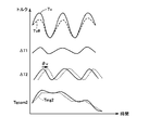
- FIG. 4 shows a setting example of the damping torque Tv.
- the damping torque Tv is a periodic torque corresponding to the crank angle CA to be applied to the crankshaft 26 in order to make the torsional damper 28 torsion constant.
- the damping torque Tv can be set in advance as a reverse-phase torque for suppressing the torque pulsation by obtaining the relationship between the torque pulsation generated when the engine 22 is motored and the crank angle CA by experiments or the like. .
- the relationship between the crank angle CA and the required damping torque Tv shown in FIG. 4 is stored in advance in the ROM 74 as a damping torque setting map.
- the crank angle CA is given, the corresponding damping torque Tv can be derived and set from the damping torque setting map. That is, FIG. 4 corresponds to an example of a damping torque setting map.
- the crank angle CA during motoring is obtained by calculation using the rotation angles of the motor generators MG1 and MG2 detected by the rotation position detection sensors 43 and 44. The point that can be done is described in a confirming manner.
- FIG. 5 is a graph showing the setting of the torque command value of motor generator MG1 when the engine is started.
- motor generator MG1 has a role of generating motoring torque when engine 22 is started.
- FIG. 5 shows the torque T1 after time ta.
- the actual torque command value is set so as to limit the change by passing the basic torque command value through a low-pass filter or the like.
- the torque controllability with respect to the torque command value decreases, and more specifically, a transient deviation increases in the output torque with respect to the torque command value, thereby overloading the battery and the power train components. This is prevented.
- the entire periodic damping torque Tv for suppressing the vibration of the engine 22 is not set to the actual torque command value Tqcom1, and the actual torque command value Tqcom1 corresponds to the damping torque Tv. Only a part of the periodic torque components is reflected. That is, it is understood that the actual torque command value Tqcom1 has an insufficient torque with respect to the damping torque Tv.
- FIG. 6 is a functional block diagram illustrating setting of torque command values of motor generators MG1 and MG2 at the time of engine start in the hybrid vehicle according to the first embodiment of the present invention.
- Each functional block shown in FIG. 6 can be realized by execution of a predetermined program (software processing) or operation of an electronic circuit (hardware processing) built in the ECU by the HVECU 70 and / or the motor ECU 45.
- base torque Tmg1 of motor generator MG1 includes motoring torque Tm shown in FIG.
- the base torque Tmg1 roughly corresponds to the motoring torque Tm.
- Damping torque calculation unit 110 calculates damping torque Tv based on the rotation angle (crank angle CA) of crankshaft 26 when flag FVL for instructing damping control is turned on when the engine is started. .
- the damping torque Tv is calculated by referring to the map shown in FIG. 4 based on the crank angle CA calculated using the rotation angles of the motor generators MG1 and MG2.
- Torque control unit 100 controls output torque of motor generators MG1 and MG2 so that damping torque Tv is ensured by motor generators MG1 and MG2 when damping torque Tv is calculated at the time of engine start. Specifically, torque command Tqcom1 of motor generator MG1 and torque command Tqcom2 of motor generator MG2 are set reflecting reflected vibration damping torque Tv.
- the torque control unit 100 includes an adding unit 120, a torque change limiting unit 130, an insufficient torque calculating unit 140, a vibration suppression assist torque calculating unit 150, a torque change limiting unit 160, and an adding unit 170.
- the addition unit 120 calculates a basic torque command value T1 by adding the base torque Tmg1 and the vibration damping torque Tv.
- the torque change limiting unit 130 generates the actual torque command value Tqcom1 so as to suppress the amount of torque change in the time axis direction with respect to the basic torque command value T1.
- the torque change limiting unit 130 is typically configured by a low-pass filter.
- FIG. 7 is a waveform diagram showing an example of a low-pass filter function by the torque change limiting unit 130.
- the basic torque command value T1 increases at a constant rate until time tb, is maintained from time tb to td, then decreases from time td, and the rate is moderate from time te.
- An example of further descending is shown.
- the actual torque command value Tqcom1 is set according to the output of the low-pass filter that receives the torque command value T1. That is, the change in the torque command value T1 on the time axis is reflected in the actual torque command value Tqcom1 according to the time constant of the low-pass filter.
- time tb the timing when the increase of the basic torque command value T1 is completed
- time tc the timing when the actual torque command value Tqcom1 matches the basic torque command value T1
- a time lag occurs. In this way, by suppressing a rapid change in the increasing direction of the torque command value, a deviation from the torque command value occurs, and the risk that an excessive torque is output from motor generator MG1 is reduced.
- the insufficient torque calculation unit 140 calculates the insufficient torque ⁇ T1 from the difference between the basic torque command value T1 and the actual torque command value Tqcom1.
- the insufficient torque ⁇ T1 mainly includes an insufficient amount with respect to the periodic change of the vibration damping torque Tv. This is because the change in the damping torque Tv is steeper than the change in the motoring torque Tm.
- the torque change limiting unit 130 limits the change in the torque command value so that only a part of the damping torque Tv calculated by the damping torque calculating unit 110 is reflected.
- Command value Tqcom1 is set.
- the torque change limiting unit 130 may limit the change of the torque command value by a method other than the low-pass filter.
- the insufficient torque calculation unit 140 may be configured to calculate the insufficient torque ⁇ T1 based on the vibration damping torque Tv by creating an arithmetic expression in consideration of the characteristics of the torque change restriction unit 130 in advance. At this time, it is also possible to calculate the insufficient torque ⁇ T1 by reflecting the limitation and characteristics in the torque control by the motor generator MG1 by feedforward.
- the vibration suppression assist torque calculation unit 150 calculates the vibration suppression assist torque ⁇ T2 based on the insufficient torque ⁇ T1 when the flag FVL # is turned on.
- Flag FVL # is turned on when vibration suppression torque is generated (flag FVL) and is in a vehicle state in which vibration suppression torque can be assisted using motor generator MG2.
- flag FVL # is turned on / off in common with flag FVL.
- the torque change limiting unit 160 is configured similarly to the torque change limiting unit 130, and smoothes the base torque Tmg2 in the time axis direction. That is, the torque change limiting unit 160 acts on the base torque Tmg2 so as to limit the amount of torque change with respect to time.
- Adder 170 generates torque command value Tqcom2 of motor generator MG2 according to the sum of base torque Tmg2 that has passed through torque change limiting unit 160 and damping assist torque ⁇ T2 calculated by damping assist torque calculator 150. .
- the damping assist torque ⁇ T2 is a part of the damping torque Tv that has not been reflected by the motor generator MG1, and therefore its temporal change is not so steep. Therefore, the damping assist torque ⁇ T can be reflected on the torque command value Tqcom2 without passing through the torque change limiting unit 160. As a result, the change in the required torque Tr is suppressed by the torque change limiting unit 160 so that the torque command value Tqcom2 does not fluctuate rapidly, and when the engine is started, the damping torque Tv in the motor generator MG1 is insufficient. Minutes can be compensated.
- the torque control unit 100 outputs a part of the damping torque Tv from the motor generator MG1, and a deficiency with respect to the damping torque Tv (insufficient torque ⁇ T1) from the motor generator MG2.
- the output torque of motor generators MG1 and MG2 is controlled so as to be assisted by the output torque (vibration assisting torque ⁇ T).
- the torque change limiting unit 130 corresponds to a “first torque calculating unit”
- the torque change limiting unit 160 and the adding unit 170 correspond to a “second torque calculating unit”.
- FIG. 8 is a flowchart showing a control processing procedure for realizing the setting of the torque command value of the motor generator at the time of engine start according to the functional block diagram shown in FIG.
- control process shown in FIG. 8 can be executed by either the HVECU 70 or the motor ECU 45, or the functions may be shared by both ECUs. Therefore, in the description of FIG. 8, the HVECU 70 and the motor ECU 45 are collectively referred to as an ECU.
- the control process shown in the flowchart of FIG. 8 is executed at predetermined intervals.
- step S ⁇ b> 100 the ECU determines whether vibration suppression control accompanying the start of engine 22 is in progress.
- the determination in step S100 can be executed based on the flag FVL shown in FIG.
- the ECU proceeds to step S110 to calculate vibration suppression torque Tv of motor generator MG1 according to crank angle CA. That is, the processing in step S110 corresponds to the function of the vibration damping torque calculation unit 110 in FIG.
- step S120 the ECU sets the torque command value Tqcom1 of the motor generator MG1 after limiting the torque change with respect to the basic torque command value T1 obtained by adding the damping torque Tv to the base torque Tmg1.
- the process in step S120 corresponds to the functions of the adding unit 120 and the torque change limiting unit 130 in FIG.
- step S130 the ECU calculates a deficient torque ⁇ T1 with respect to the vibration damping torque Tv in the motor generator MG1 due to the torque change restriction in step S120. That is, the process of step S130 corresponds to the function of the insufficient torque calculator 140 in FIG.
- step S140 the ECU calculates vibration suppression assist torque ⁇ T2 output by motor generator MG2 based on insufficient torque ⁇ T1. That is, the function of step S140 corresponds to the function of the vibration suppression assist torque calculation unit 150 in FIG. Further, in step S150, ECU 150 sets torque command value Tqcom2 with the addition of damping assist torque ⁇ T2. That is, the processing in step S150 corresponds to the functions of torque change restriction unit 160 and addition unit 170 in FIG.
- step S160 the ECU controls switching of inverters 41 and 42 in accordance with torque command values Tqcom1 and Tqcom2 of motor generators MG1 and MG2. Specifically, feedback control of the output torque of motor generators MG1 and MG2 is executed based on torque command values Tqcom1 and Tqcom2.
- a well-known control method such as pulse width modulation control or rectangular wave voltage control can be applied, and detailed description thereof is omitted.
- step S110 to S150 When the vibration suppression control is not being performed (NO in S100), the processing of steps S110 to S150 is skipped, so that in accordance with torque command values Tqcom1 and Tqcom2 in which the vibration suppression torque is not reflected, inverters 41 and 42 are performed in step S160. Be controlled.
- the HVECU 70 executes up to the setting of the base torques Tmg1 and Tmg2, and the control processing of the portion related to the periodic torque addition is preferably executed by the motor ECU 45.
- FIG. 9 shows a setting example of the torque command value of the motor generator by vibration suppression control at the time of engine start in the hybrid vehicle of the first embodiment.
- the insufficient torque ⁇ T1 is calculated from the difference between the damping torque Tv and the torque Tv #.
- the insufficient torque ⁇ T1 can be obtained from the difference between the input and output of the torque change limiting unit (low-pass filter) 130 as described with reference to FIG.
- vibration damping assist torque ⁇ T2 reflected in torque command value Tqcom2 of motor generator MG2 is calculated.
- the damping assist torque ⁇ T2 can be set by proportional calculation in consideration of the gear ratios ⁇ and Gr.
- Torque command value Tqcom2 of motor generator MG2 is set by adding damping assist torque ⁇ T2 to base torque Tmg2.
- the motoring torque Tm and the damping torque Tv of the engine 22 are obtained by the sum of the output torques of the motor generators MG1 and MG2 by torque control according to the torque command values Tqcom1 and Tqcom2. Secured.
- the torque command values Tqcom1 and Tqcom2 are suppressed from abrupt fluctuations by the torque change limiting units 130 and 160, torque pulsation during engine start-up is suppressed while ensuring torque controllability of the motor generators MG1 and MG2. Therefore, it is possible to realize the vibration suppression control that generates the vibration suppression torque Tv. As a result, it is possible to stably start the engine while suppressing the vibration of the engine.
- the torque transmission path from motor generator MG1 to crankshaft 26 and the transmission path for torque from motor generator MG2 to crankshaft 26 have different path lengths and components. Therefore, the motor generators MG1 and MG2 have different transfer functions that affect the torsional amount of the torsional damper 28.
- the periodic torque that is, damping assist torque ⁇ T2
- the periodic torque that is, damping assist torque ⁇ T2 for assisting the deficiency of damping torque Tv (insufficient torque ⁇ T1) is output from motor generator MG1. It is preferable to have a phase difference with respect to the vibration torque (Tv ⁇ T1).
- phase difference By providing such a phase difference, it is possible to more effectively suppress fluctuations in the torsional amount of the torsional damper 28 in accordance with changes in the crank angle CA, so that the effect of suppressing vibrations at the time of starting the engine 22 can be enhanced. it can.
- the necessary phase difference can be obtained in advance by actual machine experiments.
- the above-described phase difference can be provided by calculating the damping assist torque ⁇ T2 so as to have the phase difference ⁇ v with respect to the insufficient torque ⁇ T1.
- the vibration suppression auxiliary torque calculation unit 150 or step S140
- the vibration suppression auxiliary torque ⁇ T2 is converted from the insufficient torque ⁇ T1 to the vibration suppression auxiliary torque ⁇ T2 by a transfer function that performs phase advance compensation (or phase delay compensation) in addition to the proportional calculation.
- the phase difference ⁇ v can be provided.
- FIG. 10 is a configuration diagram showing a schematic configuration of the hybrid vehicle according to the second embodiment of the present invention.
- hybrid vehicle 20 according to the second embodiment differs from hybrid vehicle 20 according to the first embodiment described in FIG. 1 in that the arrangement of parking lock mechanism PL is described. .
- the configuration of other parts of the hybrid vehicle 20 is the same as that shown in FIG.
- Parking lock mechanism PL is provided for a rotating element included in a power transmission path from output shaft 48 of motor generator MG2 to drive wheels 39a and 39b via drive shaft 32a.
- the parking lock mechanism PL is provided for the drive gear 39 provided on the ring gear shaft (drive shaft) 32a.
- the parking lock mechanism PL is configured to lock the rotation of the drive gear 39 when activated, and to release the lock when not activated.
- the parking lock mechanism PL is activated when the driver selects the P range, and is deactivated when the P range is not selected.
- the drive shaft 32a constitutes a part of a torque transmission path from the motor generator MG2 to the crankshaft 26 via the power split mechanism 30. Therefore, when parking lock mechanism PL is activated and rotation of drive gear 39 is locked, the power transmission path between motor generator MG2 and crankshaft 26 is interrupted.
- the output torque of motor generator MG2 cannot be applied to crankshaft 26 when the P range is selected, that is, when parking lock mechanism PL is activated.
- the vibration suppression assist torque ⁇ T2 the vibration of the engine 22 cannot be suppressed.
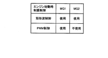
- FIG. 11 is a chart for explaining the relationship between vibration suppression control and range selection at the time of engine start in the hybrid vehicle according to the second embodiment.
- vibration suppression control is executed only by motor generator MG1 while motor generator MG2 is not used when the engine is started.
- torque command value Tqcom2 of motor generator MG2 is set without adding damping assist torque ⁇ T2 by turning off flag FLV # in FIG.
- FIG. 12 is a flowchart showing a control processing procedure for realizing the setting of the torque command value of the motor generator when starting the engine in the hybrid vehicle according to the second embodiment.
- the control process according to the flowchart shown in FIG. 12 is executed at predetermined intervals instead of the control process according to the flowchart shown in FIG.
- step S100 the ECU determines whether vibration suppression control is being performed as in FIG.
- the ECU sets the torque command value Tqcom1 of motor generator MG1 through steps S110 and S120 similar to those in FIG. 8 during vibration suppression control (when YES is determined in S100). That is, torque change of torque command value Tqcom1 is limited in order to prevent a decrease in torque controllability. As a result, the torque command value Tqcom1 reflects only a part of the damping torque Tv in step S110.
- step S180 the ECU determines whether or not the vehicle state is such that motor generator MG2 can be used for vibration suppression control.
- step S180 it is determined whether or not the P range is selected. When the P range is selected, step S180 is determined as YES, and when the P range is not selected, step S180 is determined as NO.
- the ECU When the ECU performs vibration suppression control using the motor generator MG2 (when YES is determined in S180), the ECU sets the torque command value Tqcom2 of the motor generator MG2 through steps S130 to S150 similar to FIG. That is, damping assist torque ⁇ T2 for compensating for insufficient torque ⁇ Tv1 in motor generator MG1 with respect to damping torque Tv is added to torque command value Tqcom2.
- the torque command value Tqcom2 is set based on the base torque Tmg2 without adding the vibration damping assist torque ⁇ T2.
- ECU controls switching of inverters 41 and 42 according to torque command values Tqcom1 and Tqcom2 of motor generators MG1 and MG2 at step S160 similar to FIG. Specifically, feedback control of the output torque of motor generators MG1 and MG2 is executed based on torque command values Tqcom1 and Tqcom2. As described above, when vibration suppression control is not being performed (NO in S100), steps S110 to S150 and S180 are skipped, so that step S160 is performed according to torque command values Tqcom1 and Tqcom2 in which vibration suppression torque Tv is not reflected. Thus, the inverters 41 and 42 are controlled.
- the location of the parking lock mechanism PL is not limited to the example of FIG.
- parking lock mechanism PL is arranged at any position as long as it can lock the rotation of any of the rotating elements included in the torque transmission path from motor generator MG2 to drive wheels 39a and 39b via drive shaft 32a. be able to.
- the parking lock mechanism PL arranged in this way is operated, the torque transmission path from the motor generator MG2 to the crankshaft 26 via the power split mechanism 30 is also cut off. Control can be applied.
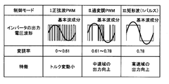
- the control mode is selected according to the state of corresponding motor generator MG1 or MG2. Specifically, either PWM control or rectangular wave voltage control is selected.
- the sine wave PWM control is used as a general PWM control.
- the on / off state of the switching element in each phase arm of an inverter (not shown) is determined by the voltage between a sine wave voltage command value and a carrier wave (typically a triangular wave). Control according to the comparison.
- the duty is set so that the fundamental wave component becomes a sine wave within a certain period. The ratio is controlled.
- this fundamental wave component (effective value) can only be increased to about 0.61 times the inverter input voltage.
- the ratio of the fundamental wave component (effective value) of the voltage (line voltage) applied to motor generators MG1 and MG2 to the DC link voltage (DC voltage VH) of inverters 41 and 42 is referred to as “modulation rate”. Called.
- an alternating current motor is applied for one pulse of a rectangular wave having a ratio of the high level period and the low level period of 1: 1 within the above-mentioned fixed period.
- the modulation rate is increased to 0.78.
- the overmodulation PWM control performs PWM control similar to the sine wave PWM control in the range where the amplitude of the voltage command is larger than the carrier wave amplitude.
- the fundamental wave component can be increased by distorting the voltage command from the original sine wave waveform, and the modulation rate can be increased from the maximum modulation rate in the sine wave PWM control to a range of 0.78. That is, when applying PWM control, it is preferable to apply overmodulation PWM control instead of sine wave PWM control in a region where the modulation factor is high.
- the induced voltage increases as the rotational speed and output torque increase, so that the required drive voltage (motor required voltage) increases.
- the DC voltage VH controlled by the converter 40 needs to be set higher than this motor required voltage.
- there is a limit value for the boosted voltage by the converter 40 that is, the DC voltage VH.
- either PWM control for controlling the amplitude and phase of the motor applied voltage (AC) by current feedback or rectangular wave voltage control is selectively performed according to the operation state of each of motor generators MG1 and MG2. Applies to In the rectangular wave voltage control, since the amplitude of the motor applied voltage is fixed, the torque control is executed by the phase control of the rectangular wave voltage pulse based on the deviation between the actual torque value and the torque command value.
- FIG. 14 shows a schematic correspondence relationship between the operation areas of motor generators MG1 and MG2 and control mode selection.
- sinusoidal PWM control is used in order to reduce torque fluctuation in the low speed region A1, overmodulation PWM control in the medium speed region A2, and rectangular wave in the high speed region A3.
- Voltage control is applied.
- the output of motor generators MG1 and MG2 is improved by applying overmodulation PWM control and rectangular wave voltage control.
- Motor ECU 45 selects one of the control modes shown in FIG. 13 within the range of modulation rates that can be realized by motor ECU 45 in accordance with the operating state of motor generators MG1 and MG2.
- the amplitude of the AC voltage applied from the inverters 41 and 42 to the motor generators MG1 and MG2 is fixed, and torque control is executed only by the voltage phase. For this reason, in the rectangular wave voltage control, the torque controllability is lowered as compared with the PWM control (particularly the sine wave PWM control).
- the time constant of the low-pass filter is set larger than when PWM control (particularly, sine wave PWM control) is selected.
- the insufficient torque ⁇ T1 in the motor generator MG1 with respect to the damping torque Tv at the time of starting the engine becomes relatively large.
- PWM control in particular, sine wave PWM control
- the output torque of motor generator MG1 according to torque command value Tqcom1 is substantially Even if the vibration (torque pulsation) at the start of the engine 22 can be prevented, the damping effect may be insufficient when the rectangular wave voltage control is selected.
- the mode of vibration suppression control at the time of engine start is switched according to the control mode of motor generator MG1 by inverter 41.
- FIG. 15 is a chart for explaining the relationship between the vibration suppression control at the time of engine start and the motor generator control mode in the hybrid vehicle according to the third embodiment.
- vibration suppression control using both motor generators MG1 and MG2 described in the first embodiment is executed when the engine is started. That is, motor generator MG1 outputs a part of damping torque Tv, and damping assist torque ⁇ T2 for compensating for insufficient torque ⁇ T1 is added to the output torque of motor generator MG2. Thereby, the deficiency of dampening torque Tv (insufficient torque ⁇ T1) is assisted by the output torque of motor generator MG2.
- the vibration suppression control at the time of engine start according to the third embodiment is performed by executing the determination at S180 in the flowchart shown in FIG. 11 based on the control mode of motor generator MG1 by inverter 41 in the second embodiment. realizable.
- the embodiment in addition to the effect of the vibration suppression control at the time of engine start according to the first embodiment, the embodiment depends on the control mode of motor generator MG1 that generates motoring torque.
- the vibration suppression control at the time of engine start by 1 can be appropriately executed.
- the configuration of the drive system of the hybrid vehicle 20 is not limited to the examples shown in FIGS. 1 and 10 for confirmation.
- the transmission 60 can be applied with the configuration described in Patent Document 1 or any other configuration.
- Patent Document 2 the configuration in which the output shaft of the motor generator MG2 and the ring gear shaft (drive shaft) 32a are connected without using the transmission 60 has been described in the present embodiment. Vibration suppression control at engine start can be applied.
- the output shafts of engine 22, motor generators MG1 and MG2 are mechanically coupled to each other by power split mechanism 30 (three-shaft power input / output mechanism) configured by a planetary gear mechanism.
- power split mechanism 30 three-shaft power input / output mechanism
- the application of the present invention is not limited to such a configuration.
- the output shafts of engine 22 and motor generators MG1 and MG2 are mechanically coupled directly or indirectly to each other, so that between engine 22 and motor generator MG1, and between engine 22 and motor generator MG2. If it is a hybrid vehicle in which the drive system is configured so that the power transmission path is configured, the vibration suppression control at the time of engine start described in the present embodiment can be applied.
- This invention can be applied to engine starting in a hybrid vehicle.
Abstract
Description
図1は、本発明の実施の形態1によるハイブリッド車両の概略構成を示す構成図である。 [Embodiment 1]
FIG. 1 is a configuration diagram showing a schematic configuration of a hybrid vehicle according to
実施の形態1では、モータジェネレータMG1およびMG2の両方を用いた、エンジン始動時の制振制御を説明した。実施の形態2では、パーキングレンジ(以下、「Pレンジ」)とも称する)で作動するパーキングロックの作動に応じた制振制御の切換えについて説明する。 [Embodiment 2]
In the first embodiment, vibration suppression control at the time of engine start using both motor generators MG1 and MG2 has been described. In the second embodiment, switching of vibration suppression control according to the operation of the parking lock that operates in the parking range (hereinafter also referred to as “P range”) will be described.
実施の形態3では、インバータ41,42による電動機制御の制御モードに応じた制振制御の切換えについて説明する。 [Embodiment 3]
In the third embodiment, switching of vibration suppression control according to the control mode of motor control by
Claims (17)
- 内燃機関(22)と、
前記内燃機関の出力軸(26a)との間に動力伝達経路を有するように構成された、前記内燃機関の始動時にモータリングトルク(Tm)を出力するための第1の電動機(MG1)と、
前記内燃機関の出力軸(26a)との間に動力伝達経路を有するように構成された第2の電動機(MG2)と、
前記内燃機関の始動時に、前記内燃機関の出力軸の回転位置(CA)に基づいて、前記内燃機関の回転に伴って生じるトルク脈動を抑制するための周期的な制振トルク(Tv)を設定するための制振トルク算出部(110)と、
前記内燃機関の始動時に、前記制振トルクのうちの一部のトルクが前記第1の電動機から出力されるとともに、前記制振トルクに対する前記一部のトルクによる不足分が前記第2の電動機からの出力トルクによって補助されるように、前記第1および前記第2の電動機の出力トルクを制御するためのトルク制御部(100)とを備える、ハイブリッド車両。 An internal combustion engine (22);
A first electric motor (MG1) configured to have a power transmission path between the output shaft (26a) of the internal combustion engine and outputting a motoring torque (Tm) when starting the internal combustion engine;
A second electric motor (MG2) configured to have a power transmission path between the output shaft (26a) of the internal combustion engine;
At the time of starting the internal combustion engine, a periodic damping torque (Tv) for suppressing torque pulsation caused by the rotation of the internal combustion engine is set based on the rotational position (CA) of the output shaft of the internal combustion engine. A damping torque calculation unit (110) for
At the time of starting the internal combustion engine, a part of the damping torque is output from the first electric motor, and a shortage due to the part of the torque with respect to the damping torque is output from the second electric motor. And a torque control unit (100) for controlling the output torque of the first and second electric motors so as to be assisted by the output torque of the hybrid vehicle. - 前記第2の電動機(MG2)の出力軸(48)から駆動軸(32a)を介して駆動輪(39a,39b)へ至る動力伝達経路に含まれる回転要素(39)の回転をロックするための、パーキングレンジの選択時に作動するパーキングロック機構(PL)をさらに備え、
前記パーキングロック機構は、前記回転要素がロックされると、前記内燃機関の出力軸(26a)および前記第2の電動機の間の動力伝達経路が遮断される位置に配置され、
前記トルク制御部(100)は、前記パーキングレンジの非選択時には、前記制振トルクの不足分を前記第2の電動機の出力トルクによって補助する一方で、前記パーキングレンジの選択時には、前記第2の電動機の出力トルクによる前記制振トルクの不足分の補助を中止する、請求の範囲第1項に記載のハイブリッド車両。 For locking the rotation of the rotary element (39) included in the power transmission path from the output shaft (48) of the second electric motor (MG2) to the drive wheels (39a, 39b) via the drive shaft (32a). And a parking lock mechanism (PL) that operates when a parking range is selected,
The parking lock mechanism is disposed at a position where the power transmission path between the output shaft (26a) of the internal combustion engine and the second electric motor is blocked when the rotating element is locked,
When the parking range is not selected, the torque control unit (100) assists the deficiency of the damping torque with the output torque of the second electric motor, while when the parking range is selected, 2. The hybrid vehicle according to claim 1, wherein assistance for a shortage of the damping torque by the output torque of the electric motor is stopped. - 前記第1の電動機(MG1)を第1のトルク指令値(Tqcom1)に従って制御するための第1のインバータ(41)と、
前記第2の電動機(MG2)を第2のトルク指令値(Tqcom2)に従って制御するための第2のインバータ(42)と、
前記第1および前記第2の電動機の動作状態に応じて、前記第1および前記第2のインバータのそれぞれによる電動機制御のモードを選択するためのモータ制御部(45)とをさらに備え、
前記モードは、矩形波電圧制御が適用される第1の制御モードおよび、正弦波パルス幅変調制御が適用される第2の制御モードを含み、
前記トルク制御部(100)は、前記第1のインバータにおいて前記第1の制御モードが選択されているときには、前記制振トルクの不足分を前記第2の電動機の出力トルクによって補助する一方で、前記第1のインバータにおいて前記第2の制御モードが選択されているときには、前記第2の電動機の出力トルクによる前記制振トルクの不足分の補助を中止する、請求の範囲第1項に記載のハイブリッド車両。 A first inverter (41) for controlling the first electric motor (MG1) according to a first torque command value (Tqcom1);
A second inverter (42) for controlling the second electric motor (MG2) according to a second torque command value (Tqcom2);
A motor control unit (45) for selecting a mode of motor control by each of the first and second inverters according to the operating state of the first and second motors;
The modes include a first control mode to which rectangular wave voltage control is applied and a second control mode to which sinusoidal pulse width modulation control is applied,
When the first control mode is selected in the first inverter, the torque control unit (100) assists the shortage of the damping torque with the output torque of the second electric motor, 2. The auxiliary device according to claim 1, wherein when the second control mode is selected in the first inverter, assistance for an insufficient amount of the damping torque due to an output torque of the second electric motor is stopped. Hybrid vehicle. - 前記トルク制御部(100)は、前記第1のインバータ(41)において前記第1の制御モードが選択されているときには、前記制振トルク(Tv)に対する前記一部のトルクの度合いを、前記第1のインバータにおいて前記第2の制御モードが選択されているときよりも低くする、請求の範囲第3項に記載のハイブリッド車両。 When the first control mode is selected in the first inverter (41), the torque control unit (100) determines the degree of the partial torque with respect to the damping torque (Tv). The hybrid vehicle according to claim 3, wherein the hybrid vehicle is set lower than when the second control mode is selected in one inverter.
- 前記トルク制御部(100)は、前記第1の電動機から出力される前記一部のトルクと、前記制振トルクの不足分を補助するために前記第2の電動機から出力される周期的なトルクとの位相が異なるように、前記第1および前記第2の電動機の出力トルクを制御する、請求の範囲第1項~第4項のいずれか1項に記載のハイブリッド車両。 The torque control unit (100) includes the partial torque output from the first electric motor and a periodic torque output from the second electric motor to assist the deficiency of the damping torque. The hybrid vehicle according to any one of claims 1 to 4, wherein output torques of the first and second electric motors are controlled so as to be different from each other in phase.
- 前記トルク制御部(100)は、
前記モータリングトルク(Tm)および前記制振トルク(Tv)の和に従う第1のトルク(T1)の時間軸方向の変化を平滑化することによって、前記第1の電動機の第1のトルク指令値(Tqcom1)を設定するための第1のトルク算出部(130)を含む、
請求の範囲第1項~第4項のいずれか1項に記載のハイブリッド車両。 The torque control unit (100)
The first torque command value of the first motor is smoothed by smoothing the change in the time axis direction of the first torque (T1) according to the sum of the motoring torque (Tm) and the damping torque (Tv). Including a first torque calculator (130) for setting (Tqcom1),
The hybrid vehicle according to any one of claims 1 to 4. - 前記トルク制御部(100)は、
前記制振トルクに対する前記不足分に対応する不足トルク(ΔT1)に基づいて、前記第2の電動機が前記制振トルクの不足分を補助するための制振補助トルク(ΔT2)を算出するための制振補助トルク算出部(140)と、
前記制振補助トルクが反映されていない段階の前記第2の電動機(MG2)のトルク指令値の時間軸方向の変化量を制限するためのトルク変化制限部(160)と、
前記トルク変化制限部の出力と、前記制振補助トルク算出部(140)によって算出された前記制振補助トルク(ΔT2)との和に従って、前記第2の電動機(MG2)の第2のトルク指令値(Tqcom2)を算出するための加算部(170)とを含む、請求の範囲第6項に記載のハイブリッド車両。 The torque control unit (100)
Based on a deficiency torque (ΔT1) corresponding to the deficiency with respect to the vibration damping torque, the second motor calculates a vibration dampening auxiliary torque (ΔT2) for assisting the deficiency in the vibration dampening torque. A vibration suppression auxiliary torque calculation unit (140);
A torque change limiting unit (160) for limiting the amount of change in the time axis direction of the torque command value of the second electric motor (MG2) at a stage where the vibration suppression assist torque is not reflected;
According to the sum of the output of the torque change limiting unit and the damping assist torque (ΔT2) calculated by the damping assist torque calculating unit (140), the second torque command of the second electric motor (MG2). The hybrid vehicle according to claim 6, further comprising an adding unit (170) for calculating a value (Tqcom2). - 前記トルク制御部(100)は、
前記内燃機関の始動時に、前記モータリングトルクに対して、前記制振トルク演算部によって設定された前記制振トルクのうちの一部のトルクを加算するように、前記第1の電動機の第1のトルク指令値(Tqcom1)を設定するための第1のトルク算出部(130)と、
前記制振トルクに対する前記不足分に対応する不足トルク(ΔT1)に基づいて、前記第2の電動機が前記制振トルクの不足分を補助するための制振補助トルク(ΔT2)を算出するための制振補助トルク算出部(140)と、
前記内燃機関の始動時に、前記制振補助トルク算出部による前記制振補助トルクを反映して前記第2の電動機の第2のトルク指令値(Tqcom2)を設定するための第2のトルク算出部(160,170)とを含む、請求の範囲第1項~第4項のいずれか1項に記載のハイブリッド車両。 The torque control unit (100)
When the internal combustion engine is started, the first motor of the first electric motor is added so that a part of the damping torque set by the damping torque calculation unit is added to the motoring torque. A first torque calculator (130) for setting a torque command value (Tqcom1) of
Based on a deficiency torque (ΔT1) corresponding to the deficiency with respect to the vibration damping torque, the second motor calculates a vibration dampening auxiliary torque (ΔT2) for assisting the deficiency in the vibration dampening torque. A vibration suppression auxiliary torque calculation unit (140);
A second torque calculation unit for setting the second torque command value (Tqcom2) of the second electric motor reflecting the vibration suppression auxiliary torque by the vibration suppression auxiliary torque calculation unit when the internal combustion engine is started. The hybrid vehicle according to any one of claims 1 to 4, further comprising (160, 170). - 前記内燃機関の出力軸(26)、前記第2の電動機(MG2)の出力軸(48)および、前記第1の電動機の出力軸の3軸に機械的に連結され、該3軸のうちのいずれか2軸の回転数が決定されると残余の1軸の回転数が決定されるとともに、該3軸のうちのいずれか2軸に入出力される動力に基づいて残余の1軸に動力を入出力するように構成された3軸式の動力入出力機構(30)をさらに備える、請求の範囲第1項~第4項のいずれか1項に記載のハイブリッド車両。 An output shaft (26) of the internal combustion engine, an output shaft (48) of the second electric motor (MG2), and an output shaft of the first electric motor are mechanically coupled to three axes, When the rotational speed of any two axes is determined, the rotational speed of the remaining one axis is determined, and power is applied to the remaining one axis based on the power input / output to / from any two of the three axes. The hybrid vehicle according to any one of claims 1 to 4, further comprising a three-shaft power input / output mechanism (30) configured to input / output the power.
- 内燃機関(22)と、前記内燃機関の出力軸(26a)との間に動力伝達経路を有するように構成された、前記内燃機関の始動時にモータリングトルク(Tm)を出力するための第1の電動機(MG1)と、前記内燃機関の出力軸(26a)との間に動力伝達経路を有するように構成された第2の電動機(MG2)とを備えたハイブリッド車両の制御方法であって、
前記内燃機関の始動時に、前記内燃機関の出力軸の回転位置(CA)に基づいて、前記内燃機関の回転に伴って生じるトルク脈動を抑制するための周期的な制振トルク(Tv)を設定するステップ(S110)と、
前記内燃機関の始動時に、前記制振トルクのうちの一部のトルクが前記第1の電動機から出力されるとともに、前記制振トルクに対する前記一部のトルクによる不足分が前記第2の電動機からの出力トルクによって補助されるように、前記第1および前記第2の電動機の出力トルクを制御するステップ(S120-S150)とを備える、ハイブリッド車両の制御方法。 A first motor for outputting a motoring torque (Tm) when the internal combustion engine is started, having a power transmission path between the internal combustion engine (22) and the output shaft (26a) of the internal combustion engine. And a second electric motor (MG2) configured to have a power transmission path between the electric motor (MG1) and the output shaft (26a) of the internal combustion engine,
At the time of starting the internal combustion engine, a periodic damping torque (Tv) for suppressing torque pulsation caused by the rotation of the internal combustion engine is set based on the rotational position (CA) of the output shaft of the internal combustion engine. Performing step (S110);
At the time of starting the internal combustion engine, a part of the damping torque is output from the first electric motor, and a shortage due to the part of the torque with respect to the damping torque is output from the second electric motor. (S120-S150) for controlling the output torque of the first and second electric motors so as to be assisted by the output torque of the hybrid vehicle. - 前記ハイブリッド車両は、
前記第2の電動機(MG2)の出力軸(48)から駆動軸(32a)を介して駆動輪(39a,39b)へ至る動力伝達経路に含まれる回転要素(39)の回転をロックするための、パーキングレンジの選択時に作動するパーキングロック機構(PL)をさらに備え、
前記パーキングロック機構は、前記回転要素がロックされると、前記内燃機関の出力軸(26a)および前記第2の電動機の間の動力伝達経路が遮断される位置に配置され、
前記制御方法は、
前記内燃機関の始動時に、前記パーキングレンジの非選択時には、前記制振トルクの不足分を前記第2の電動機の出力トルクによって補助する一方で、前記パーキングレンジの選択時には、前記第2の電動機の出力トルクによる前記制振トルクの不足分の補助を中止するステップ(S180)をさらに備える、請求の範囲第10項に記載のハイブリッド車両の制御方法。 The hybrid vehicle
For locking the rotation of the rotary element (39) included in the power transmission path from the output shaft (48) of the second electric motor (MG2) to the drive wheels (39a, 39b) via the drive shaft (32a). And a parking lock mechanism (PL) that operates when a parking range is selected,
The parking lock mechanism is disposed at a position where the power transmission path between the output shaft (26a) of the internal combustion engine and the second electric motor is blocked when the rotating element is locked,
The control method is:
When the internal combustion engine is started, when the parking range is not selected, the deficiency of the damping torque is assisted by the output torque of the second motor, while when the parking range is selected, the second motor The method for controlling a hybrid vehicle according to claim 10, further comprising a step (S180) of canceling the assist for the shortage of the damping torque by the output torque. - 前記ハイブリッド車両は、
前記第1の電動機(MG1)を第1のトルク指令値(Tqcom1)に従って制御するための第1のインバータ(41)と、
前記第2の電動機(MG2)を第2のトルク指令値(Tqcom2)に従って制御するための第2のインバータ(42)と、
前記第1および前記第2の電動機の動作状態に応じて、前記第1および前記第2のインバータのそれぞれによる電動機制御のモードを選択するためのモータ制御部(45)とをさらに備え、
前記モードは、矩形波電圧制御が適用される第1の制御モードおよび、正弦波パルス幅変調制御が適用される第2の制御モードを含み、
前記制御方法は、
前記第1のインバータにおいて前記第1の制御モードが選択されているときには、前記制振トルクの不足分を前記第2の電動機の出力トルクによって補助する一方で、前記第1のインバータにおいて前記第2の制御モードが選択されているときには、前記第2の電動機の出力トルクによる前記制振トルクの不足分の補助を中止するステップ(S180)をさらに備える、請求の範囲第10項に記載のハイブリッド車両の制御方法。 The hybrid vehicle
A first inverter (41) for controlling the first electric motor (MG1) according to a first torque command value (Tqcom1);
A second inverter (42) for controlling the second electric motor (MG2) according to a second torque command value (Tqcom2);
A motor control unit (45) for selecting a mode of motor control by each of the first and second inverters according to the operating state of the first and second motors;
The modes include a first control mode to which rectangular wave voltage control is applied and a second control mode to which sinusoidal pulse width modulation control is applied,
The control method is:
When the first control mode is selected in the first inverter, the deficiency of the damping torque is assisted by the output torque of the second motor, while the second inverter in the first inverter. The hybrid vehicle according to claim 10, further comprising a step (S180) of canceling the assist of the deficiency of the damping torque by the output torque of the second electric motor when the control mode is selected. Control method. - 前記制御するステップ(S120-S150)は、
前記第1のインバータ(41)において前記第1の制御モードが選択されているときには、前記制振トルク(Tv)に対する前記一部のトルクの度合いを、前記第1のインバータにおいて前記第2の制御モードが選択されているときよりも低くするステップ(S120)を含む、請求の範囲第12項に記載のハイブリッド車両の制御方法。 The controlling step (S120-S150) includes:
When the first control mode is selected in the first inverter (41), the degree of the partial torque with respect to the damping torque (Tv) is determined by the second control in the first inverter. The hybrid vehicle control method according to claim 12, comprising a step (S120) of lowering the mode than when the mode is selected. - 前記制御するステップ(S120-S150)は、
前記第1の電動機から出力される前記一部のトルクと、前記制振トルクの不足分を補助するために前記第2の電動機から出力される周期的なトルクとの位相が異なるように、前記第1および前記第2の電動機の出力トルクを制御するステップ(S140)を含む、請求の範囲第10項~第13項のいずれか1項に記載のハイブリッド車両の制御方法。 The controlling step (S120-S150) includes:
The phase of the partial torque output from the first electric motor and the periodic torque output from the second electric motor to assist the deficiency of the damping torque are different from each other. The method for controlling a hybrid vehicle according to any one of claims 10 to 13, including a step (S140) of controlling output torques of the first and second electric motors. - 前記制御するステップ(S120-S150)は、
前記モータリングトルク(Tm)および前記制振トルク(Tv)の和に従う第1のトルク(T1)の時間軸方向の変化を平滑化することによって、前記第1の電動機の第1のトルク指令値(Tqcom1)を設定するするステップ(S120)を含む、請求の範囲第10項~第13項のいずれか1項に記載のハイブリッド車両の制御方法。 The controlling step (S120-S150) includes:
The first torque command value of the first motor is smoothed by smoothing the change in the time axis direction of the first torque (T1) according to the sum of the motoring torque (Tm) and the damping torque (Tv). The method for controlling a hybrid vehicle according to any one of claims 10 to 13, including a step (S120) of setting (Tqcom1). - 前記制御するステップ(S120-S150)は、
前記制振トルクに対する不足分に対応する不足トルク(ΔT1)を算出するステップ(S130)と、
算出された前記不足トルクに基づいて、前記第2の電動機が前記制振トルクの不足分を補助するための制振補助トルク(ΔT2)を算出するステップ(S140)と、
前記制振補助トルク(ΔT2)が反映されていない段階の前記第2の電動機(MG2)のトルク指令値の時間軸方向の変化量を制限するとともに、制限されたトルク指令値と前記制振補助トルクとの和に従って、前記第2のトルク指令値(Tqcom2)を算出するステップ(S150)とをさらに含む、請求の範囲第15項に記載のハイブリッド車両の制御方法。 The controlling step (S120-S150) includes:
Calculating an insufficient torque (ΔT1) corresponding to an insufficient amount with respect to the vibration damping torque (S130);
A step (S140) of calculating a vibration damping assist torque (ΔT2) for the second electric motor to assist the deficiency of the vibration damping torque based on the calculated insufficient torque;
The amount of change in the time axis direction of the torque command value of the second electric motor (MG2) at the stage where the vibration suppression assist torque (ΔT2) is not reflected is limited, and the limited torque command value and the vibration suppression assist The hybrid vehicle control method according to claim 15, further comprising a step (S150) of calculating the second torque command value (Tqcom2) in accordance with a sum of the torque. - 前記制御するステップ(S120-S150)は、
前記モータリングトルクに対して、前記制振トルクのうちの一部のトルクを加算するように、前記第1の電動機の第1のトルク指令値(Tqcom1)を設定するステップ(S120)と、
前記制振トルクに対する前記一部のトルクの不足分に対応する不足トルク(ΔT1)を算出するステップ(S130)と、
算出された前記不足トルクに基づいて、前記第2の電動機による制振補助トルク(ΔT2)を算出するステップ(S140)と、
前記内燃機関の始動時に、前記制振補助トルクを反映して前記第2の電動機の第2のトルク指令値(Tqcom2)を設定するステップ(S150)とを含む、請求の範囲第10項~第13項のいずれか1項に記載のハイブリッド車両の制御方法。 The controlling step (S120-S150) includes:
Setting a first torque command value (Tqcom1) of the first electric motor so as to add a part of the damping torque to the motoring torque (S120);
Calculating an insufficient torque (ΔT1) corresponding to an insufficiency of the partial torque with respect to the damping torque (S130);
Calculating a damping assist torque (ΔT2) by the second electric motor based on the calculated insufficient torque (S140);
A step (S150) of setting a second torque command value (Tqcom2) of the second electric motor reflecting the damping assist torque at the time of starting the internal combustion engine (S150). 14. The method for controlling a hybrid vehicle according to any one of items 13.
Priority Applications (5)
| Application Number | Priority Date | Filing Date | Title |
|---|---|---|---|
| EP10852855.5A EP2581284B1 (en) | 2010-06-07 | 2010-06-07 | Hybrid vehicle and method of controlling thereof |
| US13/513,058 US8666580B2 (en) | 2010-06-07 | 2010-06-07 | Hybrid vehicle and method for controlling the same |
| CN201080054391.5A CN102639351B (en) | 2010-06-07 | 2010-06-07 | Motor vehicle driven by mixed power and control method thereof |
| JP2012519150A JP5615357B2 (en) | 2010-06-07 | 2010-06-07 | Hybrid vehicle and control method thereof |
| PCT/JP2010/059615 WO2011155015A1 (en) | 2010-06-07 | 2010-06-07 | Hybrid vehicle and method of controlling thereof |
Applications Claiming Priority (1)
| Application Number | Priority Date | Filing Date | Title |
|---|---|---|---|
| PCT/JP2010/059615 WO2011155015A1 (en) | 2010-06-07 | 2010-06-07 | Hybrid vehicle and method of controlling thereof |
Publications (2)
| Publication Number | Publication Date |
|---|---|
| WO2011155015A1 true WO2011155015A1 (en) | 2011-12-15 |
| WO2011155015A9 WO2011155015A9 (en) | 2012-07-12 |
Family
ID=45097647
Family Applications (1)
| Application Number | Title | Priority Date | Filing Date |
|---|---|---|---|
| PCT/JP2010/059615 WO2011155015A1 (en) | 2010-06-07 | 2010-06-07 | Hybrid vehicle and method of controlling thereof |
Country Status (5)
| Country | Link |
|---|---|
| US (1) | US8666580B2 (en) |
| EP (1) | EP2581284B1 (en) |
| JP (1) | JP5615357B2 (en) |
| CN (1) | CN102639351B (en) |
| WO (1) | WO2011155015A1 (en) |
Cited By (13)
| Publication number | Priority date | Publication date | Assignee | Title |
|---|---|---|---|---|
| JP2013189035A (en) * | 2012-03-12 | 2013-09-26 | Toyota Motor Corp | Control device of hybrid vehicle |
| WO2014038350A1 (en) * | 2012-09-05 | 2014-03-13 | 日産自動車株式会社 | Method for controlling and device for controlling hybrid vehicle |
| WO2014057946A1 (en) * | 2012-10-09 | 2014-04-17 | 日産自動車株式会社 | Motor control device for electric vehicle and motor control method for electric vehicle |
| CN103812422A (en) * | 2012-11-07 | 2014-05-21 | 丰田自动车株式会社 | Control system for AC electric motor |
| JP2014181691A (en) * | 2013-03-21 | 2014-09-29 | Toyota Motor Corp | Start control device for internal combustion engine |
| JP2015143053A (en) * | 2014-01-31 | 2015-08-06 | 株式会社デンソー | power control system |
| CN105555591A (en) * | 2013-09-24 | 2016-05-04 | 日立汽车系统株式会社 | Control device for electric vehicle and control method for electric vehicle |
| JP6233477B1 (en) * | 2016-09-09 | 2017-11-22 | マツダ株式会社 | Vehicle control device |
| JP2018176819A (en) * | 2017-04-04 | 2018-11-15 | トヨタ自動車株式会社 | Hybrid automobile |
| KR20190070023A (en) * | 2017-12-12 | 2019-06-20 | 현대자동차주식회사 | Method for controlling engine vibration of hybrid electric vehicle |
| JP2019119405A (en) * | 2018-01-10 | 2019-07-22 | トヨタ自動車株式会社 | Hybrid vehicle |
| JP2020184857A (en) * | 2019-05-09 | 2020-11-12 | 日野自動車株式会社 | Vehicle control device |
| US20210146784A1 (en) * | 2019-11-20 | 2021-05-20 | Denso Corporation | Motor drive device |
Families Citing this family (41)
| Publication number | Priority date | Publication date | Assignee | Title |
|---|---|---|---|---|
| KR20140033161A (en) | 2011-06-28 | 2014-03-17 | 섀플러 테크놀로지스 아게 운트 코. 카게 | Hybrid drive train having an active torsional vibration damping and method for carrying out the active torsional vibration damping |
| WO2013008312A1 (en) * | 2011-07-12 | 2013-01-17 | トヨタ自動車株式会社 | Vehicle and method for controlling vehicle |
| JP5192571B2 (en) * | 2011-07-26 | 2013-05-08 | ファナック株式会社 | Control device for driving one driven body with two electric motors |
| DE102012206559A1 (en) * | 2012-04-20 | 2013-10-24 | Bayerische Motoren Werke Aktiengesellschaft | Device for rotating Drehunförmigkeiten a drive train of a hybrid vehicle |
| US8849460B2 (en) * | 2012-05-30 | 2014-09-30 | GM Global Technology Operations LLC | Method and apparatus for determining engine pulse cancellation torque |
| US20140095002A1 (en) * | 2012-10-03 | 2014-04-03 | David Crecelius | Electric Hybrid Drive for Retrofitting to Internal Combustion Automobiles |
| DE102012218173A1 (en) * | 2012-10-05 | 2014-04-10 | Mahle International Gmbh | Motor-generator unit and operating procedures |
| TWI535622B (en) | 2013-01-25 | 2016-06-01 | li-he Yao | Bicycle electric device |
| JP5696729B2 (en) * | 2013-02-05 | 2015-04-08 | トヨタ自動車株式会社 | Vehicle control device |
| JP6255767B2 (en) * | 2013-07-24 | 2018-01-10 | 三菱自動車工業株式会社 | Automotive control device |
| DE102013220428A1 (en) * | 2013-10-10 | 2015-04-16 | Continental Automotive Gmbh | Method for controlling at least one first drive unit of a vehicle as a function of operating states of a second drive unit of the vehicle in the context of a switching operation and control device |
| JP2015098227A (en) | 2013-11-18 | 2015-05-28 | ヤマハ発動機株式会社 | Electrically-driven auxiliary vehicle |
| JP6136896B2 (en) * | 2013-11-28 | 2017-05-31 | トヨタ自動車株式会社 | Electric motor control device |
| JP5850035B2 (en) * | 2013-12-12 | 2016-02-03 | トヨタ自動車株式会社 | Control device for hybrid vehicle |
| JP2015116092A (en) * | 2013-12-13 | 2015-06-22 | トヨタ自動車株式会社 | Electric vehicle |
| JP6243279B2 (en) * | 2014-04-02 | 2017-12-06 | カルソニックカンセイ株式会社 | Driving force control device for electric vehicle |
| JP6156243B2 (en) * | 2014-04-16 | 2017-07-05 | トヨタ自動車株式会社 | Control device for hybrid vehicle |
| JP5924367B2 (en) * | 2014-05-01 | 2016-05-25 | トヨタ自動車株式会社 | Electric vehicle |
| JP6269563B2 (en) * | 2015-04-23 | 2018-01-31 | トヨタ自動車株式会社 | Hybrid car |
| US9506509B1 (en) | 2015-09-10 | 2016-11-29 | Ford Global Technologies, Llc | Clutch control using dither |
| US9758170B2 (en) | 2015-09-28 | 2017-09-12 | Ford Global Technologies, Llc | Coordinated control of transmission and accessories |
| US11159114B2 (en) * | 2016-01-19 | 2021-10-26 | Montana Technologies Llc | Electronic transmission system |
| US10479348B2 (en) | 2016-02-16 | 2019-11-19 | Ford Global Technologies, Llc | Hybrid vehicle and method of reducing engine lugging |
| JP6547676B2 (en) * | 2016-05-12 | 2019-07-24 | 株式会社デンソー | Engine start control system |
| US11686212B2 (en) | 2016-05-24 | 2023-06-27 | General Electric Company | Turbine engine and method of cooling |
| US10724443B2 (en) | 2016-05-24 | 2020-07-28 | General Electric Company | Turbine engine and method of operating |
| KR101795285B1 (en) | 2016-07-11 | 2017-11-07 | 현대자동차주식회사 | Active vibration control apparatus for hybrid electric vehicle and method thereof |
| JP6800659B2 (en) * | 2016-08-25 | 2020-12-16 | 株式会社東芝 | Hybrid vehicle system |
| US10158303B2 (en) * | 2016-09-15 | 2018-12-18 | The Boeing Company | Methods and apparatus to perform torque balance control of co-shafted motors |
| WO2018056229A1 (en) * | 2016-09-21 | 2018-03-29 | 日本精工株式会社 | Electric vehicle drive device |
| JP6614179B2 (en) * | 2017-02-16 | 2019-12-04 | トヨタ自動車株式会社 | Control device for hybrid vehicle |
| US10569763B2 (en) | 2017-07-26 | 2020-02-25 | Ford Global Technologies, Llc | HEV engine start vibration reduction system |
| CN110770104A (en) * | 2017-10-06 | 2020-02-07 | 株式会社东芝 | Hybrid vehicle |
| JP7027920B2 (en) * | 2018-02-01 | 2022-03-02 | トヨタ自動車株式会社 | Hybrid vehicle control device |
| JP6861184B2 (en) * | 2018-04-26 | 2021-04-21 | 株式会社豊田中央研究所 | Vehicle drive |
| CN108973309B (en) * | 2018-07-20 | 2021-08-17 | 温州欧宏机械有限公司 | Screen printing machine |
| JP6749375B2 (en) * | 2018-09-28 | 2020-09-02 | 株式会社Subaru | Drive system |
| DE102019100968A1 (en) * | 2019-01-16 | 2020-07-16 | Schaeffler Technologies AG & Co. KG | Method for actively damping a starting resonance of a torsion damper when starting an internal combustion engine |
| EP4046855A4 (en) * | 2019-10-16 | 2022-11-16 | Mitsubishi Jidosha Kogyo Kabushiki Kaisha | Motor control device for electric vehicle |
| CN110962855A (en) * | 2019-12-24 | 2020-04-07 | 江西麦克斯韦科技有限公司 | Torque control system and method for extended range automobile engine |
| JP7294161B2 (en) * | 2020-01-21 | 2023-06-20 | トヨタ自動車株式会社 | power train system |
Citations (3)
| Publication number | Priority date | Publication date | Assignee | Title |
|---|---|---|---|---|
| JP2007182181A (en) * | 2006-01-10 | 2007-07-19 | Toyota Motor Corp | Controller for hybrid driving device |
| JP2008024287A (en) * | 2006-06-21 | 2008-02-07 | Denso Corp | Control device of hybrid electric vehicle |
| JP2010064563A (en) * | 2008-09-09 | 2010-03-25 | Toyota Motor Corp | Hybrid vehicle and control method of internal combustion engine at starting of hybrid vehicle |
Family Cites Families (29)
| Publication number | Priority date | Publication date | Assignee | Title |
|---|---|---|---|---|
| JP3087538B2 (en) * | 1993-10-12 | 2000-09-11 | トヨタ自動車株式会社 | Internal combustion engine |
| JP3755142B2 (en) * | 1996-06-14 | 2006-03-15 | 株式会社デンソー | Vehicle vibration reduction device |
| JP3294230B2 (en) * | 2000-02-22 | 2002-06-24 | 株式会社日立製作所 | Vehicle control device, vehicle control method, transmission |
| JP2003094987A (en) * | 2001-09-20 | 2003-04-03 | Toyota Motor Corp | Control device for engine and transmission |
| DE10256993B4 (en) * | 2001-12-06 | 2018-05-09 | Denso Corporation | Control unit for an internal combustion engine |
| JP3585121B2 (en) | 2002-02-20 | 2004-11-04 | トヨタ自動車株式会社 | Power output device and automobile equipped with the same |
| US7175555B2 (en) * | 2002-03-28 | 2007-02-13 | Ford Global Technologies, Llc | Hybrid automotive powertrain with torsional vibration damper |
| JP3466600B1 (en) * | 2002-07-16 | 2003-11-10 | 本田技研工業株式会社 | Control device for hybrid vehicle |
| US7110867B2 (en) * | 2002-08-26 | 2006-09-19 | Nissan Motor Co., Ltd. | Vibration suppression apparatus and method for hybrid vehicle |
| JP2005171914A (en) * | 2003-12-12 | 2005-06-30 | Hino Motors Ltd | Air compressor |
| US7032545B2 (en) * | 2004-03-19 | 2006-04-25 | Ford Global Technologies, Llc | Multi-stroke cylinder operation in an internal combustion engine |
| US7165391B2 (en) * | 2004-03-19 | 2007-01-23 | Ford Global Technologies, Llc | Method to reduce engine emissions for an engine capable of multi-stroke operation and having a catalyst |
| US7383820B2 (en) * | 2004-03-19 | 2008-06-10 | Ford Global Technologies, Llc | Electromechanical valve timing during a start |
| US7128044B1 (en) * | 2005-05-16 | 2006-10-31 | Ford Global Technologies, Llc | Engine control with variable control valve |
| JP2007126073A (en) * | 2005-11-07 | 2007-05-24 | Nissan Motor Co Ltd | Vibration suppression device for engine |
| JP4217238B2 (en) | 2005-11-10 | 2009-01-28 | トヨタ自動車株式会社 | POWER OUTPUT DEVICE, VEHICLE MOUNTING THE SAME, DRIVE DEVICE, AND CONTROL METHOD FOR POWER OUTPUT DEVICE |
| JP4174061B2 (en) * | 2006-03-23 | 2008-10-29 | 本田技研工業株式会社 | Active vibration control device for hybrid vehicle |
| US7722498B2 (en) * | 2006-06-21 | 2010-05-25 | Denso Corporation | Control device and method for hybrid electric vehicle |
| BRPI0717522B1 (en) * | 2006-10-19 | 2020-07-14 | Toyota Jidosha Kabushiki Kaisha | VEHICLE VIBRATION DAMPING CONTROL DEVICE AND DEVICE FOR ESTIMATING A WHEEL TORQUE ACTING BETWEEN A VEHICLE WHEEL AND A ROAD SURFACE |
| JP2008162491A (en) * | 2006-12-28 | 2008-07-17 | Toyota Motor Corp | Vehicle and its control method |
| JP4277915B2 (en) * | 2007-04-03 | 2009-06-10 | 株式会社デンソー | Vehicle control device |
| JP4333767B2 (en) * | 2007-04-03 | 2009-09-16 | 株式会社デンソー | Vehicle control device |
| JP5142374B2 (en) * | 2007-12-10 | 2013-02-13 | 日立オートモティブシステムズ株式会社 | Control device for internal combustion engine |
| CN101821150B (en) * | 2007-12-14 | 2013-03-06 | 三菱电机株式会社 | Electric power-steering controller |
| JP2009247156A (en) * | 2008-03-31 | 2009-10-22 | Toyota Motor Corp | Drive force controller for vehicle |
| US20090271057A1 (en) * | 2008-04-29 | 2009-10-29 | Ise Corporation | Hybrid Vehicle Vibration Reduction System and Method |
| JP2010023790A (en) | 2008-07-24 | 2010-02-04 | Toyota Central R&D Labs Inc | Controller for electric motor |
| JP5477030B2 (en) * | 2009-05-22 | 2014-04-23 | 日産自動車株式会社 | Control device for electric vehicle |
| DE102009033544B4 (en) * | 2009-07-14 | 2018-08-23 | Volkswagen Ag | Method and device for starting an internal combustion engine |
-
2010
- 2010-06-07 CN CN201080054391.5A patent/CN102639351B/en not_active Expired - Fee Related
- 2010-06-07 WO PCT/JP2010/059615 patent/WO2011155015A1/en active Application Filing
- 2010-06-07 EP EP10852855.5A patent/EP2581284B1/en not_active Not-in-force
- 2010-06-07 US US13/513,058 patent/US8666580B2/en not_active Expired - Fee Related
- 2010-06-07 JP JP2012519150A patent/JP5615357B2/en not_active Expired - Fee Related
Patent Citations (3)
| Publication number | Priority date | Publication date | Assignee | Title |
|---|---|---|---|---|
| JP2007182181A (en) * | 2006-01-10 | 2007-07-19 | Toyota Motor Corp | Controller for hybrid driving device |
| JP2008024287A (en) * | 2006-06-21 | 2008-02-07 | Denso Corp | Control device of hybrid electric vehicle |
| JP2010064563A (en) * | 2008-09-09 | 2010-03-25 | Toyota Motor Corp | Hybrid vehicle and control method of internal combustion engine at starting of hybrid vehicle |
Non-Patent Citations (1)
| Title |
|---|
| See also references of EP2581284A4 * |
Cited By (20)
| Publication number | Priority date | Publication date | Assignee | Title |
|---|---|---|---|---|
| JP2013189035A (en) * | 2012-03-12 | 2013-09-26 | Toyota Motor Corp | Control device of hybrid vehicle |
| WO2014038350A1 (en) * | 2012-09-05 | 2014-03-13 | 日産自動車株式会社 | Method for controlling and device for controlling hybrid vehicle |
| JP5825441B2 (en) * | 2012-09-05 | 2015-12-02 | 日産自動車株式会社 | Control device and control method for hybrid vehicle |
| WO2014057946A1 (en) * | 2012-10-09 | 2014-04-17 | 日産自動車株式会社 | Motor control device for electric vehicle and motor control method for electric vehicle |
| CN103812422A (en) * | 2012-11-07 | 2014-05-21 | 丰田自动车株式会社 | Control system for AC electric motor |
| JP2014096856A (en) * | 2012-11-07 | 2014-05-22 | Toyota Motor Corp | Control system of ac motor |
| US9077269B2 (en) | 2012-11-07 | 2015-07-07 | Toyota Jidosha Kabushiki Kaisha | Control system for AC electric motor |
| JP2014181691A (en) * | 2013-03-21 | 2014-09-29 | Toyota Motor Corp | Start control device for internal combustion engine |
| CN105555591A (en) * | 2013-09-24 | 2016-05-04 | 日立汽车系统株式会社 | Control device for electric vehicle and control method for electric vehicle |
| JP2015143053A (en) * | 2014-01-31 | 2015-08-06 | 株式会社デンソー | power control system |
| JP6233477B1 (en) * | 2016-09-09 | 2017-11-22 | マツダ株式会社 | Vehicle control device |
| JP2018040330A (en) * | 2016-09-09 | 2018-03-15 | マツダ株式会社 | Control device of vehicle |
| JP2018176819A (en) * | 2017-04-04 | 2018-11-15 | トヨタ自動車株式会社 | Hybrid automobile |
| KR20190070023A (en) * | 2017-12-12 | 2019-06-20 | 현대자동차주식회사 | Method for controlling engine vibration of hybrid electric vehicle |
| KR102417546B1 (en) | 2017-12-12 | 2022-07-05 | 현대자동차주식회사 | Method for controlling engine vibration of hybrid electric vehicle |
| JP2019119405A (en) * | 2018-01-10 | 2019-07-22 | トヨタ自動車株式会社 | Hybrid vehicle |
| JP7159559B2 (en) | 2018-01-10 | 2022-10-25 | トヨタ自動車株式会社 | hybrid car |
| JP2020184857A (en) * | 2019-05-09 | 2020-11-12 | 日野自動車株式会社 | Vehicle control device |
| US20210146784A1 (en) * | 2019-11-20 | 2021-05-20 | Denso Corporation | Motor drive device |
| US11654775B2 (en) * | 2019-11-20 | 2023-05-23 | Denso Corporation | Motor drive device |
Also Published As
| Publication number | Publication date |
|---|---|
| JP5615357B2 (en) | 2014-10-29 |
| CN102639351A (en) | 2012-08-15 |
| US20120239237A1 (en) | 2012-09-20 |
| EP2581284A1 (en) | 2013-04-17 |
| CN102639351B (en) | 2015-11-25 |
| EP2581284B1 (en) | 2015-02-25 |
| EP2581284A4 (en) | 2014-03-12 |
| WO2011155015A9 (en) | 2012-07-12 |
| US8666580B2 (en) | 2014-03-04 |
| JPWO2011155015A1 (en) | 2013-08-01 |
Similar Documents
| Publication | Publication Date | Title |
|---|---|---|
| JP5615357B2 (en) | Hybrid vehicle and control method thereof | |
| JP5423898B2 (en) | Electric vehicle and control method thereof | |
| JP6009757B2 (en) | Vehicle and vehicle control method | |
| WO2012090263A1 (en) | Hybrid vehicle and control method therefor | |
| JP2013103516A (en) | Vehicle and control method for vehicle | |
| US20040055799A1 (en) | Hybrid vehicle drive control apparatus, hybrid vehicle drive control method, and program thereof | |
| JP6500872B2 (en) | Drive and car | |
| US10081267B2 (en) | Hybrid vehicle | |
| JP5673849B2 (en) | Electric vehicle and control method thereof | |
| JP5824824B2 (en) | Electric vehicle and control method thereof | |
| JP2013103514A (en) | Vehicle and control method for the same | |
| JP5758778B2 (en) | Vehicle and vehicle control method | |
| JP2003111206A (en) | Hybrid vehicle drive control system, method, and program therefor | |
| JP2008114817A (en) | Vehicle and control method therefor | |
| JP2008126809A (en) | Motive power output device, vehicle mounting same, and control method of internal combustion engine | |
| JP4215030B2 (en) | Power output apparatus, automobile equipped with the same, and control method of power output apparatus | |
| JP2018167614A (en) | Hybrid vehicular control apparatus | |
| JP2014217112A (en) | Control device of vehicle | |
| JP2013212774A (en) | Hybrid vehicle | |
| JP2016083988A (en) | Hybrid vehicle | |
| JP4039409B2 (en) | Power output apparatus, automobile equipped with the same, and control method of power output apparatus | |
| JP5696498B2 (en) | Hybrid vehicle and control method thereof | |
| JP2010221823A (en) | Hybrid vehicle | |
| JP5767083B2 (en) | Vehicle and vehicle control method | |
| JP5741030B2 (en) | Hybrid vehicle and control method thereof |
Legal Events
| Date | Code | Title | Description |
|---|---|---|---|
| WWE | Wipo information: entry into national phase |
Ref document number: 201080054391.5 Country of ref document: CN |
|
| 121 | Ep: the epo has been informed by wipo that ep was designated in this application |
Ref document number: 10852855 Country of ref document: EP Kind code of ref document: A1 |
|
| WWE | Wipo information: entry into national phase |
Ref document number: 2012519150 Country of ref document: JP |
|
| WWE | Wipo information: entry into national phase |
Ref document number: 13513058 Country of ref document: US Ref document number: 2010852855 Country of ref document: EP |
|
| NENP | Non-entry into the national phase |
Ref country code: DE |