WO2011152365A1 - エンジンシステム及び水素ステーション - Google Patents
エンジンシステム及び水素ステーション Download PDFInfo
- Publication number
- WO2011152365A1 WO2011152365A1 PCT/JP2011/062421 JP2011062421W WO2011152365A1 WO 2011152365 A1 WO2011152365 A1 WO 2011152365A1 JP 2011062421 W JP2011062421 W JP 2011062421W WO 2011152365 A1 WO2011152365 A1 WO 2011152365A1
- Authority
- WO
- WIPO (PCT)
- Prior art keywords
- engine
- hydrogen
- reactor
- pipe
- fuel
- Prior art date
- Legal status (The legal status is an assumption and is not a legal conclusion. Google has not performed a legal analysis and makes no representation as to the accuracy of the status listed.)
- Ceased
Links
Images



Classifications
-
- F—MECHANICAL ENGINEERING; LIGHTING; HEATING; WEAPONS; BLASTING
- F02—COMBUSTION ENGINES; HOT-GAS OR COMBUSTION-PRODUCT ENGINE PLANTS
- F02D—CONTROLLING COMBUSTION ENGINES
- F02D19/00—Controlling engines characterised by their use of non-liquid fuels, pluralities of fuels, or non-fuel substances added to the combustible mixtures
- F02D19/06—Controlling engines characterised by their use of non-liquid fuels, pluralities of fuels, or non-fuel substances added to the combustible mixtures peculiar to engines working with pluralities of fuels, e.g. alternatively with light and heavy fuel oil, other than engines indifferent to the fuel consumed
- F02D19/0639—Controlling engines characterised by their use of non-liquid fuels, pluralities of fuels, or non-fuel substances added to the combustible mixtures peculiar to engines working with pluralities of fuels, e.g. alternatively with light and heavy fuel oil, other than engines indifferent to the fuel consumed characterised by the type of fuels
- F02D19/0642—Controlling engines characterised by their use of non-liquid fuels, pluralities of fuels, or non-fuel substances added to the combustible mixtures peculiar to engines working with pluralities of fuels, e.g. alternatively with light and heavy fuel oil, other than engines indifferent to the fuel consumed characterised by the type of fuels at least one fuel being gaseous, the other fuels being gaseous or liquid at standard conditions
- F02D19/0644—Controlling engines characterised by their use of non-liquid fuels, pluralities of fuels, or non-fuel substances added to the combustible mixtures peculiar to engines working with pluralities of fuels, e.g. alternatively with light and heavy fuel oil, other than engines indifferent to the fuel consumed characterised by the type of fuels at least one fuel being gaseous, the other fuels being gaseous or liquid at standard conditions the gaseous fuel being hydrogen, ammonia or carbon monoxide
-
- F—MECHANICAL ENGINEERING; LIGHTING; HEATING; WEAPONS; BLASTING
- F02—COMBUSTION ENGINES; HOT-GAS OR COMBUSTION-PRODUCT ENGINE PLANTS
- F02D—CONTROLLING COMBUSTION ENGINES
- F02D19/00—Controlling engines characterised by their use of non-liquid fuels, pluralities of fuels, or non-fuel substances added to the combustible mixtures
- F02D19/06—Controlling engines characterised by their use of non-liquid fuels, pluralities of fuels, or non-fuel substances added to the combustible mixtures peculiar to engines working with pluralities of fuels, e.g. alternatively with light and heavy fuel oil, other than engines indifferent to the fuel consumed
- F02D19/0663—Details on the fuel supply system, e.g. tanks, valves, pipes, pumps, rails, injectors or mixers
- F02D19/0668—Treating or cleaning means; Fuel filters
- F02D19/0671—Means to generate or modify a fuel, e.g. reformers, electrolytic cells or membranes
-
- F—MECHANICAL ENGINEERING; LIGHTING; HEATING; WEAPONS; BLASTING
- F02—COMBUSTION ENGINES; HOT-GAS OR COMBUSTION-PRODUCT ENGINE PLANTS
- F02D—CONTROLLING COMBUSTION ENGINES
- F02D19/00—Controlling engines characterised by their use of non-liquid fuels, pluralities of fuels, or non-fuel substances added to the combustible mixtures
- F02D19/06—Controlling engines characterised by their use of non-liquid fuels, pluralities of fuels, or non-fuel substances added to the combustible mixtures peculiar to engines working with pluralities of fuels, e.g. alternatively with light and heavy fuel oil, other than engines indifferent to the fuel consumed
- F02D19/08—Controlling engines characterised by their use of non-liquid fuels, pluralities of fuels, or non-fuel substances added to the combustible mixtures peculiar to engines working with pluralities of fuels, e.g. alternatively with light and heavy fuel oil, other than engines indifferent to the fuel consumed simultaneously using pluralities of fuels
- F02D19/081—Adjusting the fuel composition or mixing ratio; Transitioning from one fuel to the other
-
- F—MECHANICAL ENGINEERING; LIGHTING; HEATING; WEAPONS; BLASTING
- F02—COMBUSTION ENGINES; HOT-GAS OR COMBUSTION-PRODUCT ENGINE PLANTS
- F02D—CONTROLLING COMBUSTION ENGINES
- F02D29/00—Controlling engines, such controlling being peculiar to the devices driven thereby, the devices being other than parts or accessories essential to engine operation, e.g. controlling of engines by signals external thereto
- F02D29/06—Controlling engines, such controlling being peculiar to the devices driven thereby, the devices being other than parts or accessories essential to engine operation, e.g. controlling of engines by signals external thereto peculiar to engines driving electric generators
-
- F—MECHANICAL ENGINEERING; LIGHTING; HEATING; WEAPONS; BLASTING
- F02—COMBUSTION ENGINES; HOT-GAS OR COMBUSTION-PRODUCT ENGINE PLANTS
- F02M—SUPPLYING COMBUSTION ENGINES IN GENERAL WITH COMBUSTIBLE MIXTURES OR CONSTITUENTS THEREOF
- F02M25/00—Engine-pertinent apparatus for adding non-fuel substances or small quantities of secondary fuel to combustion-air, main fuel or fuel-air mixture
- F02M25/10—Engine-pertinent apparatus for adding non-fuel substances or small quantities of secondary fuel to combustion-air, main fuel or fuel-air mixture adding acetylene, non-waterborne hydrogen, non-airborne oxygen, or ozone
- F02M25/12—Engine-pertinent apparatus for adding non-fuel substances or small quantities of secondary fuel to combustion-air, main fuel or fuel-air mixture adding acetylene, non-waterborne hydrogen, non-airborne oxygen, or ozone the apparatus having means for generating such gases
-
- F—MECHANICAL ENGINEERING; LIGHTING; HEATING; WEAPONS; BLASTING
- F02—COMBUSTION ENGINES; HOT-GAS OR COMBUSTION-PRODUCT ENGINE PLANTS
- F02M—SUPPLYING COMBUSTION ENGINES IN GENERAL WITH COMBUSTIBLE MIXTURES OR CONSTITUENTS THEREOF
- F02M27/00—Apparatus for treating combustion-air, fuel, or fuel-air mixture, by catalysts, electric means, magnetism, rays, sound waves, or the like
- F02M27/02—Apparatus for treating combustion-air, fuel, or fuel-air mixture, by catalysts, electric means, magnetism, rays, sound waves, or the like by catalysts
-
- F—MECHANICAL ENGINEERING; LIGHTING; HEATING; WEAPONS; BLASTING
- F01—MACHINES OR ENGINES IN GENERAL; ENGINE PLANTS IN GENERAL; STEAM ENGINES
- F01N—GAS-FLOW SILENCERS OR EXHAUST APPARATUS FOR MACHINES OR ENGINES IN GENERAL; GAS-FLOW SILENCERS OR EXHAUST APPARATUS FOR INTERNAL-COMBUSTION ENGINES
- F01N5/00—Exhaust or silencing apparatus combined or associated with devices profiting by exhaust energy
- F01N5/02—Exhaust or silencing apparatus combined or associated with devices profiting by exhaust energy the devices using heat
-
- Y—GENERAL TAGGING OF NEW TECHNOLOGICAL DEVELOPMENTS; GENERAL TAGGING OF CROSS-SECTIONAL TECHNOLOGIES SPANNING OVER SEVERAL SECTIONS OF THE IPC; TECHNICAL SUBJECTS COVERED BY FORMER USPC CROSS-REFERENCE ART COLLECTIONS [XRACs] AND DIGESTS
- Y02—TECHNOLOGIES OR APPLICATIONS FOR MITIGATION OR ADAPTATION AGAINST CLIMATE CHANGE
- Y02T—CLIMATE CHANGE MITIGATION TECHNOLOGIES RELATED TO TRANSPORTATION
- Y02T10/00—Road transport of goods or passengers
- Y02T10/10—Internal combustion engine [ICE] based vehicles
- Y02T10/12—Improving ICE efficiencies
-
- Y—GENERAL TAGGING OF NEW TECHNOLOGICAL DEVELOPMENTS; GENERAL TAGGING OF CROSS-SECTIONAL TECHNOLOGIES SPANNING OVER SEVERAL SECTIONS OF THE IPC; TECHNICAL SUBJECTS COVERED BY FORMER USPC CROSS-REFERENCE ART COLLECTIONS [XRACs] AND DIGESTS
- Y02—TECHNOLOGIES OR APPLICATIONS FOR MITIGATION OR ADAPTATION AGAINST CLIMATE CHANGE
- Y02T—CLIMATE CHANGE MITIGATION TECHNOLOGIES RELATED TO TRANSPORTATION
- Y02T10/00—Road transport of goods or passengers
- Y02T10/10—Internal combustion engine [ICE] based vehicles
- Y02T10/30—Use of alternative fuels, e.g. biofuels
Definitions
- the present invention relates to an engine system and a hydrogen station that generate hydrogen and electric power.
- Patent Document 1 proposes a “high-pressure hydrogen supply system” that generates hydrogen by dehydrogenating an organic hydride using exhaust gas from a combustion turbine power generator that generates electric power.
- Patent Document 1 the combustion turbine power generation device of Patent Document 1 is usually large and has a disadvantage of large energy loss due to operation / stop.
- an object of the present invention is to provide an engine system and a hydrogen station that can generate hydrogen and electric power with high efficiency.
- the present invention relates to an engine that burns combustion fuel and generates power, a generator that operates by the power generated by the engine and generates electric power, and an exhaust from the engine.
- An engine system comprising: a reactor heated by gas and having a catalyst that generates hydrogen and a fuel for combustion by decomposing a hydrogen-containing fuel.
- electric power can be generated with high efficiency by a generator that is operated by power generated by the engine.
- the catalyst of the reactor can be heated and activated by the high temperature exhaust gas from the engine.
- the hydrogen-containing fuel can be decomposed well, and hydrogen and combustion fuel can be generated with high efficiency. That is, by operating the engine, it is possible to generate hydrogen and combustion fuel by decomposing the hydrogen-containing fuel by effectively using the exhaust gas discharged from the engine while generating electric power with the generator.
- a hydrogen station 1 is a station in which an engine system is incorporated, and an engine 11 that burns toluene (C 7 H 14 , fuel for combustion), a generator 13,
- the compressor 14, the supercharger 21 (turbo), the hydrogen injector 23, the fuel injector 24, and the exhaust gas heat from the engine 11 are used to make MCH (methylcyclohexane, C 7 H 14 , hydrogen-containing A reactor 30 that decomposes (fuel) to produce hydrogen and toluene (see equation (1)), and a controller 70 (control means) that electronically controls the system.
- the energy efficiency of the entire system is increased by utilizing the heat of the exhaust gas in the reactor 30, that is, by recovering the energy of the exhaust gas.
- MCH methylcyclohexane
- organic hydride a hydrogen-containing fuel
- the hydrogen-containing fuel is a fuel in which hydrogen is easily added / generated, and is, for example, a hydrocarbon fuel or a mixed fuel thereof.
- the configuration using toluene as the combustion fuel is exemplified, but naphthalene, benzene, and the like can also be used.
- the combustion fuel is a fuel combustible in the engine 11, and is, for example, a hydrocarbon fuel or a mixed fuel thereof.
- the octane number of toluene (about 120) is higher than that of gasoline, which is a normal fuel for spark ignition, knocking is unlikely to occur in the engine 11, and the engine 11 is operated at a high compression ratio and combustion efficiency is increased. It is also possible to increase. Specifically, in the case of a general spark ignition type engine 11, the compression ratio of about 13 is the maximum value, but by using toluene, the compression ratio can be increased to about 15. Further, in the case of the spark ignition type engine 11, the theoretical cycle is the Otto cycle, so that the thermal efficiency is improved when the compression ratio is increased.
- the engine 11 is a four-stroke engine that repeats four cycles (intake, compression, combustion / expansion, and exhaust).
- the engine 11 includes a plurality of cylinders, a piston that reciprocates within the cylinder, a crankshaft 12 connected to the piston via a connecting rod, an intake valve and an exhaust valve that are linked to the crankshaft 12, and a controller 70. And a spark plug that is electronically controlled.
- the output of the engine 11 (rotation speed, torque, exhaust gas flow rate, etc.) is controlled by a controller 70 that controls the intake amount of fuel / air and the ignition timing.
- Such an engine 11 has a smaller energy loss due to operation / stop as compared with a turbine, and its size (displacement) can be easily changed in design. Further, the engine displacement, the number of cylinders (2 cylinders, 4 cylinders, 6 cylinders, etc.) and the arrangement (V type, in-line type, etc.) can be changed as appropriate.
- the generator 13 is a device that operates by the power of the engine 11 to generate electric power. That is, the generator 13 is mechanically connected to the crankshaft 12 of the engine 11 through a speed reduction mechanism and a clutch (not shown). Thereby, the motive power of the engine 11 is transmitted to the generator 13 without loss, and is converted into electric power by the generator 13.
- the electric power generated by the generator 13 is configured to be supplied to an electric vehicle or charged to a battery. In addition, it is good also as a structure by which surplus electric power is sold to system electric power.
- the compressor 14 is operated by the power of the engine 11 and compresses the hydrogen from the pipe 53b to increase the pressure to a predetermined pressure (for example, several MPa to several tens of MPa).
- the compressor 14 is external to hydrogen vehicles, fuel cell vehicles, hydrogen tanks, and the like. It is a device that pumps toward hydrogen demand equipment. That is, the compressor 14 is mechanically connected to the crankshaft 12 of the engine 11 via a speed reduction mechanism and a clutch (not shown). As a result, the power of the engine 11 is transmitted to the compressor 14 without loss, and is converted into hydrogen fluid energy by the compressor 14.
- the compressor 14 is connected to the crankshaft 12 and operates using the engine 11 as a power source.
- the generator 13 includes an electric motor, and the generator 13 It is good also as a structure which the said electric motor rotates when the electric power of this is supplied and the compressor 14 act
- the compressor 14 is operated by the power of the engine 11.
- a plurality of compressors 14 may be connected in series, and hydrogen compressed by one compressor 14 may be further compressed by another compressor 14 to boost the hydrogen stepwise.
- the supercharger 21, the pipe 21b, the throttle valve 22, the pipe 22a (intake port), and the engine 11 are connected in this order from the pipe 21a whose upstream end opens to the outside air toward the engine 11.
- the pipe 21a is provided with an air cleaner (not shown) for removing dust and the like.
- the hydrogen injector 23 and the fuel injector 24 are attached to the pipe 22a.
- the supercharger 21 is a device that operates by the exhaust gas discharged from the engine 11, compresses air taken into the engine 11, and supercharges the engine 11.
- the air is supercharged to the engine 11 by the supercharger 21, that is, the flow rate of the intake air is increased, so that the torque generated by the engine 11 is improved, and the thermal efficiency and output of the engine 11 are improved. It is supposed to be.
- the throttle valve 22 is a device that controls, for example, a butterfly valve and controls the flow rate of air taken into the engine 11 by controlling the opening degree of the throttle valve 22 by the controller 70.
- the hydrogen injector 23 is a device that injects hydrogen into the pipe 22 a (intake port) in accordance with a command from the controller 70 and supplies the hydrogen to the engine 11.
- the hydrogen is separated by a separator 52, which will be described later, and then led to the hydrogen injector 23 through a pipe 52a.
- the “hydrogen supply means for supplying the hydrogen generated in the reactor 30 to the engine 11” includes the pipe 51a, the second three-way valve 51, the pipe 51b, the separator 52, and the pipe 52a. And a hydrogen injector 23.
- the fuel injector 24 is a device that injects toluene into the pipe 22a (port injection) and supplies it to the engine in accordance with a command from the controller 70. Note that the position of the fuel injector 24 is not limited to this, and a structure in which fuel is injected directly into a cylinder (not shown) formed in the engine 11 may be employed. In addition, toluene is led from the tank 54 described later to the fuel injector 24 through a pipe 54a, a pump 55, and a pipe 55a.
- the “combustion fuel supply means for supplying toluene (combustion fuel) generated in the reactor 30 to the engine 11” includes the pipe 51a, the second three-way valve 51, the separator 52, and the like.
- the pipe 52b, the tank 54, the pipe 54a, the pump 55, the pipe 55a, and the fuel injector 24 are provided.
- the exhaust side of the engine 11 will be described.
- the exhaust gas outlet of the engine 11 is connected to the exhaust gas inlet of the reactor 30 through a pipe 21c, a supercharger 21, and a pipe 21d.
- the exhaust gas from the engine 11 is led to the reactor 30 after operating (rotating) the supercharger 21.
- the downstream end of the pipe 21d branches so that the exhaust gas flows outside the reaction cell 31 (see FIG. 3) and through the entire inside of the second casing 34 (see FIG. 2).
- the reactor 30 includes a plurality of reaction cells 31 whose outer shape has a columnar shape, and a cylindrical first casing 32 that accommodates the plurality of reaction cells 31.
- MCH methylcyclohexane, hydrogen-containing fuel
- high-temperature exhaust gas flows outside the reaction cell 31 and through the first casing 32.
- the first casing 32 and the second casing 34 which will be described later are made of metal (for example, SUS) so as to have high thermal conductivity.
- the shape of the 1st casing 32 and the 2nd casing 34 is not limited to a cylindrical shape, For example, a square cylinder shape and a polygonal cylinder shape may be sufficient.
- the reaction cell 31 includes a plurality of stacked reaction sheets 33 and a second casing 34 that accommodates the plurality of reaction sheets 33.
- each reaction sheet 33 includes a base metal foil 35, a porous layer 36 formed on each surface of the metal foil 35, and a catalyst 37 supported on the porous layer 36. And. That is, each reaction sheet 33 has a three-layer structure in which the porous layer 36 supported by the catalyst 37, the metal foil 35, and the porous layer 36 supported by the catalyst 37 are stacked in this order. In addition, a gap through which MCH, generated hydrogen, and toluene can flow is formed between the reaction sheets 33 adjacent to each other in the thickness direction.
- reaction sheet 33 is in the form of a sheet, its heat capacity is small, heat is quickly conducted through the reaction sheet 33, and the temperature of the catalyst 37 is quickly raised to a temperature at which the catalyst functions well. Thereby, the efficiency of the decomposition reaction which decomposes
- each reaction sheet 33 is formed with a plurality of through holes 33a. Thereby, the heat of exhaust gas is conducted well in the thickness direction, and MCH, generated hydrogen, and toluene flow well in the thickness direction.
- the metal foil 35 is made of, for example, an aluminum foil and has a thickness of about 50 to 200 ⁇ m. However, the metal foil 35 may not be provided, or instead of the metal foil 35, a porous layer serving as a base may be provided, and the entire reaction sheet 33 may have a porous structure.
- the porous layer 36 is a layer for supporting the catalyst 37 and has a plurality of pores through which MCH, generated hydrogen, and toluene can flow.
- a porous layer 36 is made of an oxide mainly composed of alumina, for example.
- Catalyst 37 is a catalyst for decomposing MCH to generate hydrogen and toluene (see formula (1)).
- a catalyst 37 is composed of at least one selected from, for example, platinum, nickel, palladium, rhodium, iridium, ruthenium, molybdenum, rhenium, tungsten, vanadium, osmium, chromium, cobalt, iron and the like.
- the exhaust gas flowing through the reactor 30 is discharged to the outside through a pipe 21e connected to the exhaust gas outlet of the reactor 30 (see FIGS. 1 and 2).
- a temperature sensor 25 is attached to the pipe 21e. The temperature sensor 25 detects the temperature T13 of the exhaust gas discharged outside after heating the reactor 30, and outputs it to the controller 70. ing.
- the MCH supply system includes a tank 41 that stores MCH, a pump 42 that pumps MCH, a normally closed injector 43, a first three-way valve 44, a first flow control valve 45, and a second flow control valve 46. And a temperature sensor 47.
- the reactor 30 sequentially passes through the pipe 41a, the pump 42, the pipe 42a, the injector 43, the pipe 43a, the first three-way valve 44, the pipe 44a, the first flow control valve 45, and the pipe 45a.
- the reaction cell 31 is connected.
- the downstream end of the pipe 45a branches into a plurality of crotches corresponding to the plurality of reaction cells 31 (see FIG. 2).
- the middle of the pipe 44a is connected to the pipe 45a on the upstream side of the branch point through the pipe 46a, the second flow rate control valve 46, and the pipe 46b.
- the injector 43 injects MCH in accordance with a command from the controller 70 while the pump 42 is operating, the injected MCH passes through the first flow control valve 45 and / or the second flow control valve 46.
- the plurality of reaction cells 31 are supplied.
- the first flow control valve 45 and the second flow control valve 46 are control valves configured to be variable in opening degree including 0 in accordance with a command from the controller 70, that is, the flow rate including 0 can be controlled. Control valve.
- a part of the pipe 45a is preheated (heated) by the exhaust gas that flows through the pipe 21d and flows toward the reactor 30 through the inside of the MCH (air when the reactor 30 is warmed up).
- the pipe 21d is arranged to be able to exchange heat.
- a part of the pipe 45a is provided in the pipe 21d so as to have a double pipe structure.
- the “first preheating part A that preheats the MCH heading toward the reactor 30 by the exhaust gas heading from the engine 11 toward the reactor 30” includes the pipe 45a and the pipe 21d arranged so as to be able to exchange heat. It consists of
- the MCH preheated in the first preheating part A can be introduced into the reactor 30, and the temperature of the catalyst 37 is maintained well.
- the air introduced into the reactor 30 can be preheated by the first preheating part A, and the temperature of the catalyst 37 can be quickly raised.
- a part of the pipe 46b is arranged to be able to exchange heat with the pipe 21e so that the MCH flowing through the pipe 46b is preheated (heated) by the exhaust gas discharged from the reactor 30.
- the “second preheating part B that preheats the MCH toward the reactor 30 by the exhaust gas discharged from the reactor 30” includes the pipe 46b and the pipe 21e.
- one of the three ports of the first three-way valve 44 is open to the outside air via the pipe 44b.
- the hydrogen / toluene lead-out system includes a second three-way valve 51, a separator 52, a normally closed on-off valve 53, a tank 54, and a pump 55.
- the plurality of reaction cells 31 are connected to a separator 52 via a pipe 51a (see FIG. 2) whose upstream side is branched into a plurality of crotches, a second three-way valve 51, and a pipe 51b.
- the hydrogen and toluene produced in the plurality of reaction cells 31 are led out to the separator 52 through the pipe 51a, the second three-way valve 51, and the pipe 51b while being mixed.
- the second three-way valve 51 is connected to the pipe 52 a via a pipe 51 c that bypasses the separator 52.
- the separator 52 is a device that separates hydrogen and toluene.
- the separator 52 cools a mixture of hydrogen and toluene by air cooling so that only toluene (boiling point: 110 ° C.) is liquefied and hydrogen and toluene are separated. . Therefore, for example, a heat radiating fin (not shown) is provided on the outer peripheral surface of the separator 52 for promoting cooling by the air cooling method.
- the separation method is not limited to this, and other methods such as a pressure swing adsorption device or a hydrogen permeable membrane (such as a Pd membrane) that selectively permeate hydrogen may be used.
- the hydrogen separated by the separator 52 is supplied to the hydrogen injector 23 through the pipe 52a.
- the structure provided with the pump which pumps hydrogen into the piping 52a may be sufficient.
- the middle of the pipe 52a is connected to the intake port of the compressor 14 through the pipe 53a, a normally closed on-off valve 53, and the pipe 53b.
- the on / off valve 53 is opened by the controller 70 and the compressor 14 is operated, hydrogen is sucked into the compressor 14.
- the toluene separated by being liquefied by the separator 52 flows through the pipe 52 b extending from the bottom of the separator 52 by its own weight, and is stored in the tank 54.
- the structure provided with the pump (not shown) which pumps toluene in the piping 52b may be sufficient.
- the toluene in the tank 54 is pumped to the fuel injector 24 through the pipe 54a, the pump 55 that operates according to the command from the controller 70, and the pipe 55a.
- the start switch 61 is a switch that is turned ON / OFF when the hydrogen station 1 is started / stopped, and is arranged at an appropriate position.
- the start switch 61 outputs the ON / OFF signal to the controller 70.
- the controller 70 is a control device that electronically controls the hydrogen station 1, and includes a CPU, a ROM, a RAM, various interfaces, an electronic circuit, and the like, and performs various functions according to programs stored therein. In addition, various devices are controlled.
- step S101 the controller 70 controls the first three-way valve 44 to connect the pipe 44a and the pipe 44b. Thereby, the piping 44a is open
- step S102 the controller 70 controls the second three-way valve 51 to cause the pipe 51a and the pipe 51c to communicate with each other. Thereby, the air which flows after this by step S103 bypasses the separator 52.
- step S ⁇ b> 103 the controller 70 operates a cell motor (not shown) for starting the engine 11, ignites with a spark plug based on the crank angle, starts the engine 11, and starts combustion of the engine 11. Specifically, the controller 70 injects toluene by the fuel injector 24 after operating the pump 55. The injection amount of toluene is controlled so as to obtain a suitable fuel-air ratio. In addition, when the remaining amount of toluene stored in the tank 54 is equal to or less than the predetermined remaining amount, the MCH in the tank 41 may be supplied to the fuel injector 24 via a pipe (not shown), and the MCH may be injected by the fuel injector 24. .
- the first flow control valve 45 is fully opened, the second flow control valve 46 is fully closed, and the hydrogen injector 23 is fully opened.
- the external air includes the pipe 44b, the first three-way valve 44, the pipe 44a, the first flow control valve 45, the pipe 45a, the plurality of reaction cells 31 (see FIG. 2), the pipe 51a, the second three-way valve 51, and the pipe. 51c, the piping 52a, and the hydrogen injector 23 are passed through in order, and the air is sucked into the piping 22a.
- the opening degree of the throttle valve 22 is reduced in order to reduce the flow rate of the air sucked from the pipe 21a side.
- the high-temperature exhaust gas preheats (heats) the air toward the reactor 30 and heats the catalyst 37 while flowing through the reaction cell 31. Further, the catalyst 37 is heated while the exhaust gas flows outside the reaction cell 31. Thereby, the reactor 30 (catalyst 37) is warmed up in a short time.
- the air heated by the exhaust gas bypasses the air-cooled separator 52, is not cooled by the separator 52, and is sucked into the engine 11 through the hydrogen injector 23 and the like while maintaining a high temperature. Thereby, the engine 11 is also warmed up in a short time.
- step S104 the controller 70 determines whether or not the temperature T11 of the air after preheating by the first preheating unit A detected via the temperature sensor 47 is equal to or higher than the first predetermined temperature T1.
- the first predetermined temperature T1 is obtained by a preliminary test or the like, and is set to a temperature at which it is determined that the reactor 30 has been warmed up (temperature at which the catalyst 37 has reached the activation temperature), for example, 500 ° C.
- step S104 When it is determined that the temperature T11 is equal to or higher than the first predetermined temperature T1 (S104 / Yes), the processing of the controller 70 proceeds to step S105. On the other hand, when it determines with temperature T11 not being 1st predetermined temperature T1 or more (S104 * No), the controller 70 repeats determination of step S104.
- step S105 the controller 70 controls the first three-way valve 44 to connect the pipe 43a and the pipe 44a.
- step S106 the controller 70 controls the second three-way valve 51 to connect the pipe 51a and the pipe 51b.
- step S107 the controller 70 starts supplying MCH. Specifically, the controller 70 injects MCH from the injector 43 after operating the pump 42. The injected MCH is supplied to each reaction cell 31 of the reactor 30 through the pipe 43a, the first three-way valve 44, the pipe 44a, the first flow rate control valve 45, and the pipe 45a. The MCH is preheated by the exhaust gas when passing through the first preheating part A.
- the separated toluene flows through the pipe 52 b by its own weight and is stored in the tank 54.
- hydrogen is supplied to the hydrogen injector 23 through the pipe 52a.
- step S201 the controller 70 turns on the first preheating part A. Specifically, the controller 70 opens the first flow control valve 45 at an appropriate opening degree and closes the second flow control valve 46. Then, MCH passes through only the first flow control valve 45 and is preheated only by the first preheating part A, and then supplied to the reactor 30.
- Step S202 the controller 70 determines whether or not the temperature T12 of the fluid in which hydrogen (gas) and toluene (gas) detected via the temperature sensor 48 are mixed is equal to or higher than the second predetermined temperature T2.
- the second predetermined temperature T2 is set to a temperature (for example, 300 ° C.) at which it is determined that the MCH decomposition reaction is proceeding well in the reactor 30 when the temperature T12 is equal to or higher than the second predetermined temperature T2.
- step S203 When it is determined that the temperature T12 is equal to or higher than the second predetermined temperature T2 (S202 / Yes), the processing of the controller 70 proceeds to step S203. On the other hand, when it determines with temperature T12 not being 2nd predetermined temperature T2 or more (S202 * No), the process of the controller 70 progresses to step S204.
- step S203 the controller 70 detects that the temperature T13 of the exhaust gas discharged from the reactor 30 detected via the temperature sensor 25 is hydrogen (gas) and toluene (gas) detected via the temperature sensor 48. It is determined whether the temperature of the mixed fluid is equal to or higher than T12.
- step S204 When it is determined that the temperature T13 is equal to or higher than the temperature T12 (S203 / Yes), the processing of the controller 70 proceeds to step S205. On the other hand, when it determines with temperature T13 not being temperature T12 or more (S203 * No), the process of the controller 70 progresses to step S204.
- step S205 the controller 70 turns on the first preheating part A and the second preheating part B. Specifically, the controller 70 opens the second flow control valve 46. Then, the MCH flows through the pipe 46b and is preheated by the second preheating part B. That is, the remaining heat of the exhaust gas is recovered.
- step S204 the controller 70 turns on the first preheating part A and turns off the second preheating part B.
- step S206 the controller 70 determines whether or not the MCH temperature T11 detected via the temperature sensor 47 is equal to or higher than a third predetermined temperature T3.
- the third predetermined temperature T3 is obtained by a preliminary test or the like. If the MCH temperature T11 is equal to or higher than the third predetermined temperature T3, for example, the third predetermined temperature T3 is set to a temperature at which the metal foil 35 built in the reactor 30 may melt. Is done.
- step S207 When it is determined that the temperature T11 is equal to or higher than the third predetermined temperature T3 (S206 / Yes), the processing of the controller 70 proceeds to step S207. On the other hand, when it is determined that the temperature T11 is not equal to or higher than the third predetermined temperature T3 (S206, No), the process of the controller 70 returns to the start through a return.
- step S207 the controller 70 controls the injector 43 so that the MCH flow rate increases.
- the temperature T11 of MCH introduced into the reactor 30 decreases and the melting of the metal foil 35 is prevented.
- step S301 the controller 70 stops the supply of MCH. Specifically, the controller 70 stops the pump 42 and the injector 43.
- step S302 the controller 70 continues the combustion (operation) of the engine 11, and sucks and removes MCH, toluene, and hydrogen remaining in the reactor 30 and upstream / downstream thereof with the engine 11. Note that the process of step S302 is executed for a predetermined time (for example, 5 minutes).
- step S303 the controller 70 controls the first three-way valve 44 to connect the pipe 44a and the pipe 44b. Thereby, the piping 44a is open
- step S304 the controller 70 continues the combustion (operation) of the engine 11. Then, external air passes through the pipe 44b, the pipe 44a (the pipe 46a, the pipe 46b), the reactor 30 (in the reaction cell 31), the pipe 51a, the separator 52, the pipe 52a, and the hydrogen injector 23 to the engine 11. Inhaled. Then, the catalyst surface is activated by supplying air to the reactor 30 (inside the reaction cell 31) warmed by the exhaust gas of the engine 11, and as a result, deterioration of the catalyst 37 is suppressed, and the reactor 30 is a long life. At that time, since the air is sent to the reactor 30 by the pumping during the intake stroke of the engine 11, system efficiency is improved because external power such as a pump is not used. Note that the process of step S304 is executed for a predetermined time (for example, 5 minutes).
- step S305 the controller 70 stops the combustion of the engine 11.
- step S306 the controller 70 controls the first three-way valve 44 to connect the pipe 44a and the pipe 43a. Thereby, the piping 44a is interrupted from outside air, and outside air does not flow into the reactor 30 while the system is stopped.
- the configuration in which the engine system is incorporated in the hydrogen station has been exemplified.
- a configuration in which the engine system is incorporated in a hydrogen vehicle or a hybrid vehicle may be used.
- Hydrogen station (engine system) DESCRIPTION OF SYMBOLS 11 Engine 13 Generator 14 Compressor 21 Supercharger 23 Hydrogen injector (hydrogen supply means) 24 Fuel injector (fuel supply means for combustion) 30 reactor 31 reaction cell 32 first casing 34 second casing 70 controller (control means) A 1st preheating part B 2nd preheating part
Landscapes
- Engineering & Computer Science (AREA)
- Chemical & Material Sciences (AREA)
- Combustion & Propulsion (AREA)
- Mechanical Engineering (AREA)
- General Engineering & Computer Science (AREA)
- Oil, Petroleum & Natural Gas (AREA)
- Chemical Kinetics & Catalysis (AREA)
- Output Control And Ontrol Of Special Type Engine (AREA)
- Control Of Vehicle Engines Or Engines For Specific Uses (AREA)
- Supercharger (AREA)
- Fuel Cell (AREA)
Abstract
水素及び電力を高効率で生成可能とするエンジンシステム及び水素ステーションを提供する。トルエン(燃焼用燃料)を燃焼し、動力を発生するエンジン(11)と、エンジン(11)で発生した動力により作動し電力を生成する発電機(13)と、エンジン(11)からの排気ガスで加熱され、MCH(水素含有燃料)を分解することで水素及びトルエンを生成する触媒を有する反応器(30)と、を備えることを特徴とする水素ステーション(1)(エンジンシステム)である。
Description
本発明は、水素及び電力を生成するエンジンシステム及び水素ステーションに関する。
近年、水素自動車や燃料電池車等の開発・実用化が進められており、これに並行して、水素自動車や燃料電池車等に、その燃料となる水素を供給するための水素ステーションの開発・実用化も進められている。例えば、特許文献1では、電力を発生する燃焼タービン発電装置からの排気ガスを利用して、有機ハイドライドを脱水素反応させ、水素を生成する「高圧水素の供給システム」が提案されている。
しかしながら、特許文献1の燃焼タービン発電装置は、通常、大型であり、運転・停止に伴うエネルギロスが大きいという不都合があった。
そこで、本発明は、水素及び電力を高効率で生成可能とするエンジンシステム及び水素ステーションを提供することを課題とする。
前記課題を解決するための手段として、本発明は、燃焼用燃料を燃焼し、動力を発生するエンジンと、前記エンジンで発生した動力により作動し電力を生成する発電機と、前記エンジンからの排気ガスで加熱され、水素含有燃料を分解することで水素及び燃焼用燃料を生成する触媒を有する反応器と、を備えることを特徴とするエンジンシステムである。
このようなエンジンシステムによれば、エンジンで発生した動力により作動する発電機によって、電力を高効率で生成できる。また、エンジンからの高温の排気ガスによって、反応器の触媒を加熱し活性化できる。そして、この活性化した触媒によって、水素含有燃料を良好に分解し、水素及び燃焼用燃料を高効率で生成できる。
すなわち、エンジンを作動させることで、発電機で電力を生成しつつ、エンジンから排出された排気ガスを有効利用して、水素含有燃料を分解し、水素及び燃焼用燃料を生成できる。
すなわち、エンジンを作動させることで、発電機で電力を生成しつつ、エンジンから排出された排気ガスを有効利用して、水素含有燃料を分解し、水素及び燃焼用燃料を生成できる。
本発明によれば、水素及び電力を高効率で生成可能とするエンジンシステム及び水素ステーションを提供することができる。そして、本発明の諸側面および効果、並びに、他の効果およびさらなる特徴は、添付の図面を参照して後述する本発明の例示的かつ非制限的な実施の形態の詳細な説明により、一層明らかとなるであろう。
以下、本発明の一実施形態について、図1~図6を参照して説明する。
≪水素ステーションの構成≫
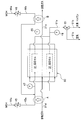
図1に示すように、本実施形態に係る水素ステーション1は、エンジンシステムが組み込まれたステーションであって、トルエン(C7H14、燃焼用燃料)を燃焼するエンジン11と、発電機13と、圧縮機14と、過給器21(ターボ)と、水素インジェクタ23と、燃料インジェクタ24と、エンジン11からの排気ガスの熱を利用して、MCH(メチルシクロヘキサン、C7H14、水素含有燃料)を分解し水素及びトルエンを生成する反応器30と(式(1)参照)、システムを電子制御するコントローラ70(制御手段)と、を備えている。
図1に示すように、本実施形態に係る水素ステーション1は、エンジンシステムが組み込まれたステーションであって、トルエン(C7H14、燃焼用燃料)を燃焼するエンジン11と、発電機13と、圧縮機14と、過給器21(ターボ)と、水素インジェクタ23と、燃料インジェクタ24と、エンジン11からの排気ガスの熱を利用して、MCH(メチルシクロヘキサン、C7H14、水素含有燃料)を分解し水素及びトルエンを生成する反応器30と(式(1)参照)、システムを電子制御するコントローラ70(制御手段)と、を備えている。
C7H14(MCH)→C7H14(トルエン)+3H2-205kj …(1)
なお、式(1)は吸熱反応であるから、反応器30において排気ガスの熱を利用することにより、つまり、排気ガスのエネルギを回収することにより、システム全体のエネルギ効率を高めている。
<MCH、トルエン>
すなわち、本実施形態では、水素含有燃料(有機ハイドライド)として、MCH(メチルシクロヘキサン)を使用した構成を例示するが、その他に例えば、シクロヘキサン、デカリン等も使用できる。なお、水素含有燃料とは、水素を容易に添加・生成する燃料であって、例えば、炭化水素系燃料やその混合燃料である。
すなわち、本実施形態では、水素含有燃料(有機ハイドライド)として、MCH(メチルシクロヘキサン)を使用した構成を例示するが、その他に例えば、シクロヘキサン、デカリン等も使用できる。なお、水素含有燃料とは、水素を容易に添加・生成する燃料であって、例えば、炭化水素系燃料やその混合燃料である。
また、本実施形態では、燃焼用燃料(エンジン駆動用燃料)として、トルエンを使用した構成を例示するが、その他に例えば、ナフタレン、ベンゼン等も使用できる。なお、燃焼用燃料とは、エンジン11で燃焼可能な燃料であって、例えば、炭化水素系燃料やその混合燃料である。
そして、トルエンのオクタン価(約120)は、通常の火花点火用の燃料であるガソリンに対して高いので、エンジン11でノッキングが発生し難く、また、高圧縮比でエンジン11を作動させ、燃焼効率を高めることも可能となっている。具体的には、一般的な火花点火式のエンジン11の場合、圧縮比13程度が最大値であるが、トルエンを使用することにより、圧縮比15程度に高めることも可能となる。さらに、火花点火式のエンジン11の場合、理論サイクルがオットーサイクルであるから、圧縮比が高くなると、熱効率が向上する関係である。
<エンジン>
エンジン11は、4サイクル(吸気、圧縮、燃焼・膨張、排気)を繰り返す4ストローク機関である。エンジン11は、複数の気筒(シリンダ)と、気筒内を往復運動するピストンと、ピストンにコンロッドを介して接続されたクランク軸12と、クランク軸12に連動する吸気弁及び排気弁と、コントローラ70により電子制御される点火プラグと、を備えている。エンジン11の出力(回転速度、トルク、排気ガスの流量等)は、燃料・空気の吸気量、点火タイミングを制御するコントローラ70で制御される。
エンジン11は、4サイクル(吸気、圧縮、燃焼・膨張、排気)を繰り返す4ストローク機関である。エンジン11は、複数の気筒(シリンダ)と、気筒内を往復運動するピストンと、ピストンにコンロッドを介して接続されたクランク軸12と、クランク軸12に連動する吸気弁及び排気弁と、コントローラ70により電子制御される点火プラグと、を備えている。エンジン11の出力(回転速度、トルク、排気ガスの流量等)は、燃料・空気の吸気量、点火タイミングを制御するコントローラ70で制御される。
なお、このようなエンジン11は、タービンと比較して、運転・停止に伴うエネルギロスは小さく、その大きさ(排気量)等は設計変更容易である。また、エンジンの排気量や、気筒の数(2気筒、4気筒、6気筒等)及び配列(V型、直列型等)は、適宜変更自由である。
<発電機>
発電機13は、エンジン11の動力によって作動し電力を生成する装置である。すなわち、発電機13は、減速機構及びクラッチ(図示しない)を介して、エンジン11のクランク軸12と機械的に接続されている。これにより、エンジン11の動力がロス無く発電機13に伝達し、発電機13で電力に変換されるようになっている。
なお、発電機13で生成した電力は、電気自動車に供給されたり、バッテリに充電されるように構成されている。その他、余剰電力が系統電力に売電される構成としてもよい。
発電機13は、エンジン11の動力によって作動し電力を生成する装置である。すなわち、発電機13は、減速機構及びクラッチ(図示しない)を介して、エンジン11のクランク軸12と機械的に接続されている。これにより、エンジン11の動力がロス無く発電機13に伝達し、発電機13で電力に変換されるようになっている。
なお、発電機13で生成した電力は、電気自動車に供給されたり、バッテリに充電されるように構成されている。その他、余剰電力が系統電力に売電される構成としてもよい。
<圧縮機>
圧縮機14は、エンジン11の動力によって作動し、配管53bからの水素を圧縮して所定圧力(例えば、数MPa~数十MPa)に昇圧し、水素自動車、燃料電池車、水素タンク等の外部の水素需要機器に向けて圧送する装置である。すなわち、圧縮機14は、減速機構及びクラッチ(図示しない)を介して、エンジン11のクランク軸12と機械的に接続されている。これにより、エンジン11の動力がロス無く圧縮機14に伝達し、圧縮機14で水素の流体エネルギに変換されるようになっている。
圧縮機14は、エンジン11の動力によって作動し、配管53bからの水素を圧縮して所定圧力(例えば、数MPa~数十MPa)に昇圧し、水素自動車、燃料電池車、水素タンク等の外部の水素需要機器に向けて圧送する装置である。すなわち、圧縮機14は、減速機構及びクラッチ(図示しない)を介して、エンジン11のクランク軸12と機械的に接続されている。これにより、エンジン11の動力がロス無く圧縮機14に伝達し、圧縮機14で水素の流体エネルギに変換されるようになっている。
なお、ここでは、圧縮機14がクランク軸12に接続され、エンジン11を動力源として作動する構成を例示しているが、その他に例えば、発電機13が電動モータを内蔵し、発電機13からの電力が供給されると前記電動モータが回転し、圧縮機14が作動する構成としてもよい。この構成の場合も、圧縮機14は、エンジン11の動力によって作動することになる。
その他、複数の圧縮機14を直列で接続し、一の圧縮機14で圧縮された水素を、他の圧縮機14でさらに圧縮し、水素を段階的に昇圧する構成としてもよい。
その他、複数の圧縮機14を直列で接続し、一の圧縮機14で圧縮された水素を、他の圧縮機14でさらに圧縮し、水素を段階的に昇圧する構成としてもよい。
次に、エンジン11の吸気側を説明する。
上流端が外部の空気に開口した配管21aから、エンジン11に向かって順に、過給器21、配管21b、スロットル弁22、配管22a(吸気ポート)、エンジン11の順に接続されている。配管21aには、塵等を除去するエアクリーナ(図示しない)が設けられている。そして、水素インジェクタ23及び燃料インジェクタ24は、配管22aに取り付けられている。
上流端が外部の空気に開口した配管21aから、エンジン11に向かって順に、過給器21、配管21b、スロットル弁22、配管22a(吸気ポート)、エンジン11の順に接続されている。配管21aには、塵等を除去するエアクリーナ(図示しない)が設けられている。そして、水素インジェクタ23及び燃料インジェクタ24は、配管22aに取り付けられている。
<過給器>
過給器21は、エンジン11から排出された排気ガスにより作動し、エンジン11に吸気される空気を圧縮しエンジン11に過給する装置である。このように、過給器21によって空気がエンジン11に過給、つまり、吸気される空気の流量が増加するので、エンジン11で生成するトルクが向上し、また、エンジン11の熱効率及び出力が向上するようになっている。
過給器21は、エンジン11から排出された排気ガスにより作動し、エンジン11に吸気される空気を圧縮しエンジン11に過給する装置である。このように、過給器21によって空気がエンジン11に過給、つまり、吸気される空気の流量が増加するので、エンジン11で生成するトルクが向上し、また、エンジン11の熱効率及び出力が向上するようになっている。
スロットル弁22は、例えば、バタフライ弁で構成され、その開度がコントローラ70で制御されることで、エンジン11に吸気される空気の流量を制御する装置である。
<水素インジェクタ(水素供給手段)>
水素インジェクタ23は、コントローラ70からの指令に従って、水素を配管22a(吸気ポート)に噴射し、エンジン11に供給する装置である。なお、水素は、後記する分離器52で分離された後、配管52aを介して、水素インジェクタ23に導かれている。
水素インジェクタ23は、コントローラ70からの指令に従って、水素を配管22a(吸気ポート)に噴射し、エンジン11に供給する装置である。なお、水素は、後記する分離器52で分離された後、配管52aを介して、水素インジェクタ23に導かれている。
ここで、本実施形態において、「反応器30で生成した水素をエンジン11に供給する水素供給手段」は、配管51aと、第2三方弁51と、配管51bと、分離器52と、配管52aと、水素インジェクタ23と、を備えて構成されている。
そして、このようにして、燃焼速度の大きい水素がエンジン11に供給されるので、エンジン11において、希薄・均一燃焼が可能となり、また、ポンピングロスも低減される。また、エンジン11内の混合気(トルエン、水素、空気が混合したもの)の比熱比(定容比熱(Cv)/定圧比熱(Cp))が向上し、エンジン11の熱効率を高めることができる。
<燃料インジェクタ(燃焼用燃料供給手段)>
燃料インジェクタ24は、コントローラ70からの指令に従って、トルエンを配管22aに噴射し(ポート噴射)、エンジンに供給する装置である。なお、燃料インジェクタ24の位置はこれに限定されず、エンジン11内に形成された気筒(図示しない)に直接噴射する構成でもよい。また、トルエンは、後記するタンク54から、配管54a、ポンプ55、配管55aを介して、燃料インジェクタ24に導かれている。
燃料インジェクタ24は、コントローラ70からの指令に従って、トルエンを配管22aに噴射し(ポート噴射)、エンジンに供給する装置である。なお、燃料インジェクタ24の位置はこれに限定されず、エンジン11内に形成された気筒(図示しない)に直接噴射する構成でもよい。また、トルエンは、後記するタンク54から、配管54a、ポンプ55、配管55aを介して、燃料インジェクタ24に導かれている。
ここで、本実施形態において、「反応器30で生成したトルエン(燃焼用燃料)をエンジン11に供給する燃焼用燃料供給手段」は、配管51aと、第2三方弁51と、分離器52と、配管52bと、タンク54と、配管54aと、ポンプ55と、配管55aと、燃料インジェクタ24と、を備えて構成されている。
そして、このようにして高オクタン価のトルエンがエンジン11に供給されるので、前記したように、エンジン11でノッキングが発生し難くなり、エンジン11を高圧縮比で作動させ、燃焼効率を高めることも可能となる。
次に、エンジン11の排気側を説明する。
エンジン11の排気ガス出口は、配管21c、過給器21、配管21dを介して、反応器30の排気ガス入口に接続されている。そして、エンジン11からの排気ガスは、過給器21を作動(回転)させた後、反応器30に導かれるようになっている。なお、配管21dの下流端は、排気ガスが反応セル31(図3参照)の外であって第2ケーシング34内の全体を通流するように分岐している(図2参照)。
エンジン11の排気ガス出口は、配管21c、過給器21、配管21dを介して、反応器30の排気ガス入口に接続されている。そして、エンジン11からの排気ガスは、過給器21を作動(回転)させた後、反応器30に導かれるようになっている。なお、配管21dの下流端は、排気ガスが反応セル31(図3参照)の外であって第2ケーシング34内の全体を通流するように分岐している(図2参照)。
<反応器>
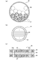
反応器30は、図2、図3(a)に示すように、外形が円柱状を呈する複数本の反応セル31と、複数の反応セル31を収容した円筒状の第1ケーシング32と、を備えている。そして、MCH(メチルシクロヘキサン、水素含有燃料)が各反応セル31内を通流し、高温の排気ガスが反応セル31の外であって第1ケーシング32内を通流するようになっている。
反応器30は、図2、図3(a)に示すように、外形が円柱状を呈する複数本の反応セル31と、複数の反応セル31を収容した円筒状の第1ケーシング32と、を備えている。そして、MCH(メチルシクロヘキサン、水素含有燃料)が各反応セル31内を通流し、高温の排気ガスが反応セル31の外であって第1ケーシング32内を通流するようになっている。
第1ケーシング32及び後記する第2ケーシング34は、熱伝導率が高くなるように金属製(例えば、SUS)で形成されている。なお、第1ケーシング32、第2ケーシング34の形状は、円筒状に限定されず、その他に例えば、四角形筒状、多角形筒状でもよい。
<反応セル>
反応セル31は、図3(b)に示すように、積層された複数枚の反応シート33と、複数枚の反応シート33を収容した第2ケーシング34と、を備えている。
反応セル31は、図3(b)に示すように、積層された複数枚の反応シート33と、複数枚の反応シート33を収容した第2ケーシング34と、を備えている。
各反応シート33は、図3(c)に示すように、ベースとなる金属箔35と、金属箔35の両面にそれぞれ形成された多孔質層36と、多孔質層36に担持された触媒37と、を備えている。つまり、各反応シート33は、触媒37が担持した多孔質層36、金属箔35、触媒37が担持した多孔質層36の順で積層した三層構造である。
なお、厚さ方向において隣り合う反応シート33、33間には、MCH、生成した水素及びトルエンが通流可能な隙間が形成されている。
なお、厚さ方向において隣り合う反応シート33、33間には、MCH、生成した水素及びトルエンが通流可能な隙間が形成されている。
また、反応シート33はシート状であるから、その熱容量が小さく、熱が反応シート33を速やかに伝導し、触媒37がその触媒機能を良好に発揮する温度に速やかに昇温する。これにより、MCHを水素とトルエンとに分解する分解反応の効率は、高くなっている。
さらに、各反応シート33には、複数の貫通孔33aが形成されている。これにより、排気ガスの熱が厚さ方向に良好に伝導し、また、MCH、生成した水素及びトルエンが、厚さ方向にも良好に通流するようになっている。
金属箔35は、例えばアルミニウム箔で構成され、その厚さは50~200μm程度とされる。
ただし、金属箔35を備えず、又は、金属箔35に代えて、ベースとなる多孔質層を備え、反応シート33全体を多孔質構造としてもよい。
ただし、金属箔35を備えず、又は、金属箔35に代えて、ベースとなる多孔質層を備え、反応シート33全体を多孔質構造としてもよい。
多孔質層36は、触媒37を担持するための層であって、MCH、生成した水素及びトルエンが通流可能な複数の細孔を有している。このような多孔質層36は、例えば、アルミナを主体とする酸化物で構成される。
触媒37は、MCHを分解し、水素及びトルエンを生成させるための触媒である(式(1)参照)。このような触媒37は、例えば、白金、ニッケル、パラジウム、ロジウム、イリジウム、ルテニウム、モリブデン、レニウム、タングステン、バナジウム、オスミウム、クロム、コバルト、鉄等から選択された少なくとも1種で構成される。
なお、反応器30を通流した排気ガスは、反応器30の排気ガス出口に接続された配管21eを通って外部に排出されるようになっている(図1、図2参照)。
そして、配管21eには、温度センサ25が取り付けられており、温度センサ25は、反応器30の加熱後、外部に排出される排気ガスの温度T13を検出し、コントローラ70に出力するようになっている。
そして、配管21eには、温度センサ25が取り付けられており、温度センサ25は、反応器30の加熱後、外部に排出される排気ガスの温度T13を検出し、コントローラ70に出力するようになっている。
<MCH供給系>
次に、図1、図2を参照して、反応器30に、MCHを供給するMCH供給系について説明する。
MCH供給系は、MCHを貯溜するタンク41と、MCHを圧送するポンプ42と、常閉型のインジェクタ43と、第1三方弁44と、第1流量制御弁45と、第2流量制御弁46と、温度センサ47と、を備えている。
次に、図1、図2を参照して、反応器30に、MCHを供給するMCH供給系について説明する。
MCH供給系は、MCHを貯溜するタンク41と、MCHを圧送するポンプ42と、常閉型のインジェクタ43と、第1三方弁44と、第1流量制御弁45と、第2流量制御弁46と、温度センサ47と、を備えている。
タンク41から、下流に向かって、配管41a、ポンプ42、配管42a、インジェクタ43、配管43a、第1三方弁44、配管44a、第1流量制御弁45、配管45aを順に介して、反応器30の反応セル31に接続されている。なお、配管45aの下流端は、複数の反応セル31に対応して複数股に分岐している(図2参照)。
また、配管44aの途中は、配管46a、第2流量制御弁46、配管46bを介して、前記した分岐点よりも上流側で配管45aに接続されている。
また、配管44aの途中は、配管46a、第2流量制御弁46、配管46bを介して、前記した分岐点よりも上流側で配管45aに接続されている。
そして、ポンプ42が作動している状態で、コントローラ70からの指令に従ってインジェクタ43がMCHを噴射すると、噴射されたMCHが、第1流量制御弁45及び/又は第2流量制御弁46を通って、複数の反応セル31に供給されるようになっている。
なお、第1流量制御弁45及び第2流量制御弁46は、コントローラ70からの指令に従って、0を含めて開度を可変可能に構成された制御弁、つまり、0を含めて流量を制御可能な制御弁である。
なお、第1流量制御弁45及び第2流量制御弁46は、コントローラ70からの指令に従って、0を含めて開度を可変可能に構成された制御弁、つまり、0を含めて流量を制御可能な制御弁である。
<第1予熱部>
また、配管45aの一部は、その内部を通流するMCH(反応器30の暖機時は空気)が、配管21dを通流し反応器30に向かう排気ガスによって予熱(加熱)されるように、配管21dと熱交換可能に配置されている。具体的に例えば、配管45aの一部は、配管21d内に二重管構造となるように設けられる。
また、配管45aの一部は、その内部を通流するMCH(反応器30の暖機時は空気)が、配管21dを通流し反応器30に向かう排気ガスによって予熱(加熱)されるように、配管21dと熱交換可能に配置されている。具体的に例えば、配管45aの一部は、配管21d内に二重管構造となるように設けられる。
したがって、本実施形態において、「エンジン11から反応器30に向かう排気ガスによって、反応器30に向かうMCHを予熱する第1予熱部A」は、熱交換可能に配置された配管45aと配管21dとで構成されている。
これにより、第1予熱部Aで予熱されたMCHを反応器30に導入でき、触媒37の温度が良好に維持されるようになっている。また、システム起動時には、第1予熱部Aによって、反応器30に導入される空気を予熱でき、触媒37が速やかに昇温されるようになっている。
<第2予熱部>
また、配管46bの一部は、その内部を通流するMCHが、反応器30から排出された排気ガスによって予熱(加熱)されるように、配管21eと熱交換可能に配置されている。
また、配管46bの一部は、その内部を通流するMCHが、反応器30から排出された排気ガスによって予熱(加熱)されるように、配管21eと熱交換可能に配置されている。
したがって、本実施形態において、「反応器30から排出された排気ガスによって、反応器30に向かうMCHを予熱する第2予熱部B」は、配管46bと配管21eとで構成されている。
これにより、外部に排出される排気ガスの温度が高く、排熱が余っている場合、第2予熱部Bによってこれを回収し、反応器30に向かうMCHを予熱することで、エネルギ効率を高めることができる。
これにより、外部に排出される排気ガスの温度が高く、排熱が余っている場合、第2予熱部Bによってこれを回収し、反応器30に向かうMCHを予熱することで、エネルギ効率を高めることができる。
また、第1三方弁44の3つのポートのうち1つのポートは、配管44bを介して外部の空気に開放されている。
<水素・トルエン導出系>
次に、反応器30で生成した水素及びトルエンを導出する水素・トルエン導出系を説明する。
水素・トルエン導出系は、第2三方弁51と、分離器52と、常閉型の開閉弁53と、タンク54と、ポンプ55と、を備えている。
次に、反応器30で生成した水素及びトルエンを導出する水素・トルエン導出系を説明する。
水素・トルエン導出系は、第2三方弁51と、分離器52と、常閉型の開閉弁53と、タンク54と、ポンプ55と、を備えている。
複数の反応セル31は、上流側が複数股に分岐した配管51a(図2参照)、第2三方弁51、配管51bを介して、分離器52に接続されている。そして、複数の反応セル31で生成した水素及びトルエンは、混在したまま、配管51a、第2三方弁51、配管51bを通って、分離器52に導出されるようになっている。
また、第2三方弁51は、分離器52をバイパスする配管51cを介して、配管52aに接続されている。
また、第2三方弁51は、分離器52をバイパスする配管51cを介して、配管52aに接続されている。
分離器52は、水素とトルエンとを分離する装置である。
本実施形態に係る分離器52は、水素及びトルエンが混在したものを空冷式で冷却することで、トルエン(沸点:110℃)のみを液化させ、水素とトルエンとを分離するようになっている。よって、例えば、分離器52の外周面には、空冷式による冷却を促進するための放熱フィン(図示しない)が設けられている。
なお、分離方式はこれに限定されず、その他に例えば、圧力スイング吸着装置、水素を選択的に透過する水素透過膜(Pd膜等)によって水素を分離する方式でもよい。
本実施形態に係る分離器52は、水素及びトルエンが混在したものを空冷式で冷却することで、トルエン(沸点:110℃)のみを液化させ、水素とトルエンとを分離するようになっている。よって、例えば、分離器52の外周面には、空冷式による冷却を促進するための放熱フィン(図示しない)が設けられている。
なお、分離方式はこれに限定されず、その他に例えば、圧力スイング吸着装置、水素を選択的に透過する水素透過膜(Pd膜等)によって水素を分離する方式でもよい。
そして、分離器52で分離された水素は、配管52aを通って、水素インジェクタ23に供給されるようになっている。
なお、配管52aに水素を圧送するポンプが設けられた構成でもよい。
なお、配管52aに水素を圧送するポンプが設けられた構成でもよい。
また、配管52aの途中は、配管53a、常閉型の開閉弁53、配管53bを介して、圧縮機14の吸気口に接続されている。そして、コントローラ70によって開閉弁53が開かれ、圧縮機14が作動すると、水素が圧縮機14に吸気されるようになっている。
一方、分離器52で液化することで分離されたトルエンは、分離器52の底部から延びる配管52bを自重により通流し、タンク54で貯溜されるようになっている。
なお、配管52bにトルエンを圧送するポンプ(図示しない)が設けられた構成でもよい。
なお、配管52bにトルエンを圧送するポンプ(図示しない)が設けられた構成でもよい。
タンク54内のトルエンは、配管54a、コントローラ70からの指令に従って作動するポンプ55、配管55aを通って、燃料インジェクタ24に圧送されるようになっている。
<その他機器>
起動スイッチ61は、水素ステーション1を起動/停止する場合に、ON/OFFされるスイッチであり、適所に配置されている。そして、起動スイッチ61は、そのON/OFF信号を、コントローラ70に出力されるようになっている。
起動スイッチ61は、水素ステーション1を起動/停止する場合に、ON/OFFされるスイッチであり、適所に配置されている。そして、起動スイッチ61は、そのON/OFF信号を、コントローラ70に出力されるようになっている。
<コントローラ>
コントローラ70は、水素ステーション1を電子制御する制御装置であり、CPU、ROM、RAM、各種インタフェイス、電子回路などを含んで構成されており、その内部に記憶されたプログラムに従って、各種機能を発揮し、各種機器を制御するようになっている。
コントローラ70は、水素ステーション1を電子制御する制御装置であり、CPU、ROM、RAM、各種インタフェイス、電子回路などを含んで構成されており、その内部に記憶されたプログラムに従って、各種機能を発揮し、各種機器を制御するようになっている。
≪水素ステーションの動作・効果≫
次に、水素ステーション1の動作・効果について、図4~図6を参照して説明する。
次に、水素ステーション1の動作・効果について、図4~図6を参照して説明する。
<起動時>
まず、水素ステーション1の起動時について、図4を参照して説明する。なお、起動スイッチ61がONされると、図4に示す処理がスタートする。
まず、水素ステーション1の起動時について、図4を参照して説明する。なお、起動スイッチ61がONされると、図4に示す処理がスタートする。
ステップS101において、コントローラ70は、第1三方弁44を制御し、配管44aと配管44bとを連通させる。これにより、配管44aは、第1三方弁44、配管44bを介して、外部の空気に開放される。
ステップS102において、コントローラ70は、第2三方弁51を制御し、配管51aと配管51cとを連通させる。これにより、この後、ステップS103で通流する空気が、分離器52をバイパスすることになる。
ステップS103において、コントローラ70は、エンジン11の始動用のセルモータ(図示しない)を作動させ、クランク角に基づいて点火プラグで着火し、エンジン11を始動させ、エンジン11の燃焼を開始させる。
具体的には、コントローラ70は、ポンプ55を作動した後、燃料インジェクタ24によって、トルエンを噴射する。トルエンの噴射量は、好適な燃空比となるように制御する。
なお、タンク54に貯溜されたトルエンの残量が所定残量以下ある場合、タンク41のMCHを図示しない配管を介して燃料インジェクタ24に供給し、燃料インジェクタ24でMCHを噴射する構成としてもよい。
具体的には、コントローラ70は、ポンプ55を作動した後、燃料インジェクタ24によって、トルエンを噴射する。トルエンの噴射量は、好適な燃空比となるように制御する。
なお、タンク54に貯溜されたトルエンの残量が所定残量以下ある場合、タンク41のMCHを図示しない配管を介して燃料インジェクタ24に供給し、燃料インジェクタ24でMCHを噴射する構成としてもよい。
また、第1流量制御弁45を全開とし、第2流量制御弁46を全閉とし、水素インジェクタ23を全開とする。このような状態でエンジン11が作動すると、ピストンの往復運動に伴ってエンジン11で発生した負圧により、外部の空気が吸気される。
すなわち、外部の空気は、配管44b、第1三方弁44、配管44a、第1流量制御弁45、配管45a、複数の反応セル31(図2参照)、配管51a、第2三方弁51、配管51c、配管52a、水素インジェクタ23を順に通って、配管22aに吸気される。
この場合において、配管21a側から吸気される空気の流量を少なくするために、スロットル弁22の開度は小さくする。
この場合において、配管21a側から吸気される空気の流量を少なくするために、スロットル弁22の開度は小さくする。
また、エンジン11が始動すると、エンジン11において高温の排気ガスが生成し、この排気ガスが、配管21c、過給器21、配管21d、反応器30、配管21eを通って、外部に排出される。
そうすると、第1予熱部Aにおいて、高温の排気ガスが反応器30に向かう空気を予熱(加熱)し、この空気が反応セル31内を通流しながら、触媒37を加熱する。また、排気ガスが反応セル31外を通流しながら、触媒37を加熱する。これにより、反応器30(触媒37)が短時間で暖機される。
さらに、排気ガスで加熱された空気が、空冷式の分離器52をバイパスし、分離器52で冷却されず、高温のまま、水素インジェクタ23等を通って、エンジン11に吸気される。これにより、エンジン11も短時間で暖機される。
ステップS104において、コントローラ70は、温度センサ47を介して検出される第1予熱部Aによる予熱後の空気の温度T11が第1所定温度T1以上であるか否か判定する。
第1所定温度T1は、事前試験等により求められ、反応器30の暖機が完了したと判断される温度(触媒37が活性温度に到達したと判断される温度)、例えば500℃に設定される。
第1所定温度T1は、事前試験等により求められ、反応器30の暖機が完了したと判断される温度(触媒37が活性温度に到達したと判断される温度)、例えば500℃に設定される。
温度T11は第1所定温度T1以上であると判定した場合(S104・Yes)、コントローラ70の処理は、ステップS105に進む。一方、温度T11は第1所定温度T1以上でないと判定した場合(S104・No)、コントローラ70は、ステップS104の判定を繰り返す。
ステップS105において、コントローラ70は、第1三方弁44を制御し、配管43aと配管44aとを連通させる。
ステップS106において、コントローラ70は、第2三方弁51を制御し、配管51aと配管51bとを連通させる。
ステップS107において、コントローラ70は、MCHの供給を開始する。
具体的には、コントローラ70は、ポンプ42を作動させた後、インジェクタ43からMCHを噴射する。噴射されたMCHは、配管43a、第1三方弁44、配管44a、第1流量制御弁45、配管45aを通って、反応器30の各反応セル31に供給される。なお、MCHは、第1予熱部Aを通過する際、排気ガスによって予熱される。
具体的には、コントローラ70は、ポンプ42を作動させた後、インジェクタ43からMCHを噴射する。噴射されたMCHは、配管43a、第1三方弁44、配管44a、第1流量制御弁45、配管45aを通って、反応器30の各反応セル31に供給される。なお、MCHは、第1予熱部Aを通過する際、排気ガスによって予熱される。
そうすると、各反応セル31では、MCHが触媒37下で分解し、水素とトルエンとが生成する。そして、水素とトルエンとは、混在したまま、配管51a、第2三方弁51、配管51bを通って、分離器52に導出される。次いで、分離器52において空冷式にて冷却され、水素(気体)とトルエン(液体)とに分離される。
そして、分離されたトルエンは、自重によって、配管52bを通流し、タンク54で貯溜される。一方、水素は、配管52aを通って、水素インジェクタ23に供給される。
その後、コントローラ70の処理は、エンドに進み、図5に示す定常時のフローチャートに移行する。
<定常時>
次に、水素ステーション1の定常運転時(定常時)について、図5を参照して説明する。
次に、水素ステーション1の定常運転時(定常時)について、図5を参照して説明する。
ステップS201において、コントローラ70は、第1予熱部AをONする。
具体的には、コントローラ70は、第1流量制御弁45を適宜な開度で開き、第2流量制御弁46を閉じる。そうすると、MCHは、第1流量制御弁45のみを通り、第1予熱部Aのみで予熱された後、反応器30に供給される。
具体的には、コントローラ70は、第1流量制御弁45を適宜な開度で開き、第2流量制御弁46を閉じる。そうすると、MCHは、第1流量制御弁45のみを通り、第1予熱部Aのみで予熱された後、反応器30に供給される。
ステップS202において、コントローラ70は、温度センサ48を介して検出される水素(気体)及びトルエン(気体)が混在した流体の温度T12が第2所定温度T2以上であるか否か判定する。
第2所定温度T2は、温度T12が第2所定温度T2以上であれば、反応器30におけるMCHの分解反応が良好に進行していると判断される温度(例えば300℃)に設定される。
第2所定温度T2は、温度T12が第2所定温度T2以上であれば、反応器30におけるMCHの分解反応が良好に進行していると判断される温度(例えば300℃)に設定される。
温度T12は第2所定温度T2以上であると判定した場合(S202・Yes)、コントローラ70の処理は、ステップS203に進む。一方、温度T12は第2所定温度T2以上でないと判定した場合(S202・No)、コントローラ70の処理は、ステップS204に進む。
ステップS203において、コントローラ70は、温度センサ25を介して検出される反応器30から排出された排気ガスの温度T13が、温度センサ48を介して検出される水素(気体)及びトルエン(気体)が混在した流体の温度T12以上であるか否か判定する。
温度T13は温度T12以上であると判定した場合(S203・Yes)、コントローラ70の処理は、ステップS205に進む。一方、温度T13は温度T12以上でないと判定した場合(S203・No)、コントローラ70の処理は、ステップS204に進む。
ステップS205において、コントローラ70は、第1予熱部A及び第2予熱部BをONする。具体的には、コントローラ70は、第2流量制御弁46を開く。そうすると、MCHが、配管46bを通流し、第2予熱部Bによって予熱される。つまり、排気ガスの余っている熱が回収される。
ステップS204において、コントローラ70は、第1予熱部AをONし、第2予熱部BをOFFする。
ステップS206において、コントローラ70は、温度センサ47を介して検出されるMCHの温度T11が第3所定温度T3以上であるか否か判定する。
第3所定温度T3は、事前試験等により求められ、MCHの温度T11が第3所定温度T3以上であると、例えば、反応器30に内蔵される金属箔35が溶融する虞のある温度に設定される。
第3所定温度T3は、事前試験等により求められ、MCHの温度T11が第3所定温度T3以上であると、例えば、反応器30に内蔵される金属箔35が溶融する虞のある温度に設定される。
温度T11は第3所定温度T3以上であると判定した場合(S206・Yes)、コントローラ70の処理はステップS207に進む。一方、温度T11は第3所定温度T3以上でないと判定した場合(S206・No)、コントローラ70の処理はリターンを通ってスタートに戻る。
ステップS207において、コントローラ70は、MCHの流量が増加するように、インジェクタ43を制御する。そして、MCHの流量が増加すると、反応器30に導入されるMCHの温度T11が低下し、金属箔35の溶融が防止される。
その後、コントローラ70の処理は、リターンを通ってスタートに戻る。
<停止時>
次に、水素ステーション1の停止時について、図6を参照して説明する。なお、起動スイッチ61がOFFされると、図6に示す処理がスタートする。
次に、水素ステーション1の停止時について、図6を参照して説明する。なお、起動スイッチ61がOFFされると、図6に示す処理がスタートする。
ステップS301において、コントローラ70は、MCHの供給を停止する。具体的には、コントローラ70は、ポンプ42及びインジェクタ43を停止する。
ステップS302において、コントローラ70は、エンジン11の燃焼(作動)を継続させ、反応器30やその上流/下流に残留するMCH、トルエン、水素をエンジン11で吸引し、除去する。
なお、ステップS302の処理は、所定時間(例えば5分)の間、実行される。
なお、ステップS302の処理は、所定時間(例えば5分)の間、実行される。
ステップS303において、コントローラ70は、第1三方弁44を制御し、配管44aと配管44bとを連通させる。これにより、配管44aは配管44bを介して外部の空気に開放される。
ステップS304において、コントローラ70は、エンジン11の燃焼(作動)を継続させる。そうすると、外部の空気が、配管44b、配管44a(配管46a、配管46b)、反応器30(反応セル31内)、配管51a、分離器52、配管52a、水素インジェクタ23を通って、エンジン11に吸気される。そうすると、エンジン11の排気ガスで温められている反応器30(反応セル31内)に空気が供給されることで触媒表面が活性化処理され、その結果、触媒37の劣化が抑制され、反応器30が長寿命となる。またその際、エンジン11の吸気行程時のポンピングによって反応器30に空気が送られるため、ポンプ等の外部動力を使わないことから、システム効率が向上する。
なお、ステップS304の処理は、所定時間(例えば5分)の間、実行される。
なお、ステップS304の処理は、所定時間(例えば5分)の間、実行される。
ステップS305において、コントローラ70は、エンジン11の燃焼を停止させる。
ステップS306において、コントローラ70は、第1三方弁44を制御して、配管44aと配管43aとを連通させる。これにより、配管44aは外部の空気と遮断され、システム停止中に、外部の空気が反応器30に流入することはない。
その後、コントローラ70の処理は、エンドに進み、システム停止状態となる。
≪変形例≫
以上、本発明の一実施形態について説明したが、本発明はこれに限定されず、例えば次のように変更できる。
以上、本発明の一実施形態について説明したが、本発明はこれに限定されず、例えば次のように変更できる。
前記した実施形態では、エンジンシステムが水素ステーションに組み込まれた構成を例示したが、その他に例えば、エンジンシステムが水素自動車やハイブリッド車に組み込まれた構成でもよい。
1 水素ステーション(エンジンシステム)
11 エンジン
13 発電機
14 圧縮機
21 過給器
23 水素インジェクタ(水素供給手段)
24 燃料インジェクタ(燃焼用燃料供給手段)
30 反応器
31 反応セル
32 第1ケーシング
34 第2ケーシング
70 コントローラ(制御手段)
A 第1予熱部
B 第2予熱部
11 エンジン
13 発電機
14 圧縮機
21 過給器
23 水素インジェクタ(水素供給手段)
24 燃料インジェクタ(燃焼用燃料供給手段)
30 反応器
31 反応セル
32 第1ケーシング
34 第2ケーシング
70 コントローラ(制御手段)
A 第1予熱部
B 第2予熱部
Claims (10)
- 燃焼用燃料を燃焼し、動力を発生するエンジンと、
前記エンジンで発生した動力により作動し電力を生成する発電機と、
前記エンジンからの排気ガスで加熱され、水素含有燃料を分解することで水素及び燃焼用燃料を生成する触媒を有する反応器と、
を備える
ことを特徴とするエンジンシステム。 - 前記エンジンで発生した動力により作動し、前記反応器で生成した水素を圧縮し外部に供給する圧縮機を備える
ことを特徴とする請求の範囲第1項に記載のエンジンシステム。 - 前記反応器で生成した燃焼用燃料を前記エンジンに供給する燃焼用燃料供給手段を備える
ことを特徴とする請求の範囲第1項に記載のエンジンシステム。 - 前記反応器で生成した水素を前記エンジンに供給する水素供給手段を備える
ことを特徴とする請求の範囲第1項に記載のエンジンシステム。 - 前記エンジンから排出された排気ガスによって作動し、外部から前記エンジンに吸気される空気を過給する過給器を備える
ことを特徴とする請求の範囲第1項に記載のエンジンシステム。 - 前記反応器は、反応セルと、前記反応セルを収容する第1ケーシングと、を備え、
前記反応セルは、前記触媒を含む複数の積層された反応シートと、前記複数の反応シートを収容する筒状の第2ケーシングと、を備え、
排気ガスが、前記反応セルの外であって、前記第1ケーシング内を通流し、
水素含有燃料が、前記反応セル内を通流する
ことを特徴とする請求の範囲第1項に記載のエンジンシステム。 - 前記水素含有燃料を前記反応器に供給する配管の一部には三方弁を介して空気が流通する配管が接続されており、
前記三方弁を切り替えることで空気または前記水素含有燃料が前記反応器に供給され、
前記エンジンの吸引力により前記反応器から空気または水素をエンジンに供給する
ことを特徴とする請求の範囲第1項に記載のエンジンシステム。 - 前記エンジンから前記反応器に向かう排気ガスによって、前記反応器に向かう水素含有燃料を予熱する第1予熱部を備える
ことを特徴とする請求の範囲第1項に記載のエンジンシステム。 - 前記反応器から排出された排気ガスによって、前記反応器に向かう水素含有燃料を予熱する第2予熱部を備える
ことを特徴とする請求の範囲第1項に記載のエンジンシステム。 - 請求の範囲第1項に記載のエンジンシステムを備える
ことを特徴とする水素ステーション。
Applications Claiming Priority (2)
| Application Number | Priority Date | Filing Date | Title |
|---|---|---|---|
| JP2010124005A JP5508146B2 (ja) | 2010-05-31 | 2010-05-31 | エンジンシステム及び水素ステーション |
| JP2010-124005 | 2010-05-31 |
Publications (1)
| Publication Number | Publication Date |
|---|---|
| WO2011152365A1 true WO2011152365A1 (ja) | 2011-12-08 |
Family
ID=45066731
Family Applications (1)
| Application Number | Title | Priority Date | Filing Date |
|---|---|---|---|
| PCT/JP2011/062421 Ceased WO2011152365A1 (ja) | 2010-05-31 | 2011-05-30 | エンジンシステム及び水素ステーション |
Country Status (2)
| Country | Link |
|---|---|
| JP (1) | JP5508146B2 (ja) |
| WO (1) | WO2011152365A1 (ja) |
Cited By (1)
| Publication number | Priority date | Publication date | Assignee | Title |
|---|---|---|---|---|
| WO2013042499A1 (ja) * | 2011-09-22 | 2013-03-28 | 株式会社日立製作所 | 動力変換システム |
Families Citing this family (1)
| Publication number | Priority date | Publication date | Assignee | Title |
|---|---|---|---|---|
| JP2026043790A (ja) * | 2024-08-29 | 2026-03-12 | カワサキモータース株式会社 | 内燃機関システム、内燃機関システムを備えた乗物、及び、燃料供給装置の制御方法 |
Citations (3)
| Publication number | Priority date | Publication date | Assignee | Title |
|---|---|---|---|---|
| JP2008144614A (ja) * | 2006-12-07 | 2008-06-26 | Mitsui Eng & Shipbuild Co Ltd | 揮発性有機化合物の廃液改質システム |
| JP2009196530A (ja) * | 2008-02-22 | 2009-09-03 | Toyota Motor Corp | 燃料改質装置 |
| JP2010083687A (ja) * | 2008-09-30 | 2010-04-15 | Hitachi Ltd | 水素貯蔵システム |
-
2010
- 2010-05-31 JP JP2010124005A patent/JP5508146B2/ja not_active Expired - Fee Related
-
2011
- 2011-05-30 WO PCT/JP2011/062421 patent/WO2011152365A1/ja not_active Ceased
Patent Citations (3)
| Publication number | Priority date | Publication date | Assignee | Title |
|---|---|---|---|---|
| JP2008144614A (ja) * | 2006-12-07 | 2008-06-26 | Mitsui Eng & Shipbuild Co Ltd | 揮発性有機化合物の廃液改質システム |
| JP2009196530A (ja) * | 2008-02-22 | 2009-09-03 | Toyota Motor Corp | 燃料改質装置 |
| JP2010083687A (ja) * | 2008-09-30 | 2010-04-15 | Hitachi Ltd | 水素貯蔵システム |
Cited By (3)
| Publication number | Priority date | Publication date | Assignee | Title |
|---|---|---|---|---|
| WO2013042499A1 (ja) * | 2011-09-22 | 2013-03-28 | 株式会社日立製作所 | 動力変換システム |
| JP2013068163A (ja) * | 2011-09-22 | 2013-04-18 | Hitachi Ltd | 動力変換システム |
| EP2759691A4 (en) * | 2011-09-22 | 2015-05-27 | Hitachi Ltd | POWER CONVERSION SYSTEM |
Also Published As
| Publication number | Publication date |
|---|---|
| JP5508146B2 (ja) | 2014-05-28 |
| JP2011247234A (ja) | 2011-12-08 |
Similar Documents
| Publication | Publication Date | Title |
|---|---|---|
| JP4039383B2 (ja) | 水素利用内燃機関 | |
| JP4687666B2 (ja) | エンジンシステム | |
| CN102007286B (zh) | 内燃机用氢供给装置及内燃机的运转方法 | |
| KR102185298B1 (ko) | 수성 유체 분사를 동반하는 내연 기관 | |
| WO2003033888A1 (en) | Internal combustion fuel reforming | |
| JP7157832B2 (ja) | 燃料改質装置 | |
| JP5575549B2 (ja) | エネルギー生成システム | |
| JP5508146B2 (ja) | エンジンシステム及び水素ステーション | |
| WO2013042500A1 (ja) | 動力変換システム | |
| JP4052847B2 (ja) | 燃料改質装置を備えたガスエンジン | |
| JP2009281200A (ja) | 水素エンジンを搭載した車両の制御装置 | |
| JP2010151000A (ja) | 改質器付エンジンシステム | |
| JPH06288692A (ja) | 熱交換器及びそれを用いたアルコール改質エンジン | |
| CN118793502A (zh) | 内燃机气缸外尾气催化还原综合处理系统及其运行方法 | |
| RU2016151527A (ru) | Способ подачи топлива в двс и система с парогенератором для его осуществления | |
| US7654072B2 (en) | Method and apparatus for generating compressed air from liquefied air, for supplying compressed air to an engine | |
| JP2025125467A (ja) | エンジン搭載車両の燃料改質システム | |
| JP2024110816A (ja) | 車両の燃料改質システム | |
| JP2024110818A (ja) | 車両の制御システム | |
| JP5480862B2 (ja) | 動力変換システム | |
| JP5696215B2 (ja) | エンジンシステム | |
| JP2012109150A (ja) | 燃料電池システムおよび車両 | |
| JP5861867B2 (ja) | 燃料電池システム | |
| RU2005106674A (ru) | Электрохимический генератор | |
| FR2839583A1 (fr) | Installation de piles a combustible et vehicule equipe d'une telle installation |
Legal Events
| Date | Code | Title | Description |
|---|---|---|---|
| 121 | Ep: the epo has been informed by wipo that ep was designated in this application |
Ref document number: 11789768 Country of ref document: EP Kind code of ref document: A1 |
|
| NENP | Non-entry into the national phase |
Ref country code: DE |
|
| 122 | Ep: pct application non-entry in european phase |
Ref document number: 11789768 Country of ref document: EP Kind code of ref document: A1 |