WO2011132517A1 - 芯出し装置および芯出し方法 - Google Patents
芯出し装置および芯出し方法 Download PDFInfo
- Publication number
- WO2011132517A1 WO2011132517A1 PCT/JP2011/058384 JP2011058384W WO2011132517A1 WO 2011132517 A1 WO2011132517 A1 WO 2011132517A1 JP 2011058384 W JP2011058384 W JP 2011058384W WO 2011132517 A1 WO2011132517 A1 WO 2011132517A1
- Authority
- WO
- WIPO (PCT)
- Prior art keywords
- workpiece
- amount
- force
- centering
- eccentricity
- Prior art date
- Legal status (The legal status is an assumption and is not a legal conclusion. Google has not performed a legal analysis and makes no representation as to the accuracy of the status listed.)
- Ceased
Links
Images



Classifications
-
- B—PERFORMING OPERATIONS; TRANSPORTING
- B23—MACHINE TOOLS; METAL-WORKING NOT OTHERWISE PROVIDED FOR
- B23Q—DETAILS, COMPONENTS, OR ACCESSORIES FOR MACHINE TOOLS, e.g. ARRANGEMENTS FOR COPYING OR CONTROLLING; MACHINE TOOLS IN GENERAL CHARACTERISED BY THE CONSTRUCTION OF PARTICULAR DETAILS OR COMPONENTS; COMBINATIONS OR ASSOCIATIONS OF METAL-WORKING MACHINES, NOT DIRECTED TO A PARTICULAR RESULT
- B23Q3/00—Devices holding, supporting, or positioning work or tools, of a kind normally removable from the machine
- B23Q3/18—Devices holding, supporting, or positioning work or tools, of a kind normally removable from the machine for positioning only
- B23Q3/183—Centering devices
-
- B—PERFORMING OPERATIONS; TRANSPORTING
- B23—MACHINE TOOLS; METAL-WORKING NOT OTHERWISE PROVIDED FOR
- B23Q—DETAILS, COMPONENTS, OR ACCESSORIES FOR MACHINE TOOLS, e.g. ARRANGEMENTS FOR COPYING OR CONTROLLING; MACHINE TOOLS IN GENERAL CHARACTERISED BY THE CONSTRUCTION OF PARTICULAR DETAILS OR COMPONENTS; COMBINATIONS OR ASSOCIATIONS OF METAL-WORKING MACHINES, NOT DIRECTED TO A PARTICULAR RESULT
- B23Q16/00—Equipment for precise positioning of tool or work into particular locations not otherwise provided for
- B23Q16/02—Indexing equipment
- B23Q16/04—Indexing equipment having intermediate members, e.g. pawls, for locking the relatively movable parts in the indexed position
- B23Q16/06—Rotary indexing
Definitions
- the present invention relates to a centering device and a centering method.
- a lathe process or a grinding process is performed on the ring-shaped workpiece.
- a lathe process or a grinding process is performed on the ring-shaped workpiece.
- Patent Document 1 a mechanical automatic centering device has been proposed (Patent Document 1 and Patent Document 2) regardless of the centering by skilled workers.
- a centering device described in Patent Document 1 includes a rotation angle position detector that detects a rotation angle position of a rotary table, a radial deviation detector that detects a radial deviation of a workpiece, and detection by the detector.
- the centering device described in Patent Document 2 includes a first measuring unit, a first position adjusting unit, a second measuring unit, a second position adjusting unit, a position fixing unit, a control unit, and the like. It is.
- Patent Document 1 has a digital scale for measuring the amount of eccentricity in the mechanism of the correction head. For this reason, the structure of the entire apparatus is complicated and expensive. Moreover, when centering a large workpiece with such an apparatus, a large load is applied to the correction head. For this reason, the member which supports this head receives the reaction force of this load. Therefore, it has been difficult to accurately attach a cage for measuring the amount of eccentricity to such a member.
- the present invention provides a centering device and a centering method capable of simplifying the entire apparatus and capable of stably centering a workpiece.
- the centering device of the present invention is a centering device that performs centering of a workpiece by applying an impact force to the workpiece by a hammer means, a rotating table for rotating the workpiece, a striking force applied to the workpiece, Control means for calculating an impact force to be applied next in order to correct the eccentric amount of the current workpiece based on the workpiece movement amount by the impact, and the hammer with the impact force calculated by the control means.
- the work is hit by means.
- the impact force applied to the workpiece by the hammer means is calculated by the control means so as to obtain an optimum impact force for each impact.
- the hammer means strikes the workpiece with the optimum striking force calculated by the control means, and the eccentricity of the workpiece can be corrected. That is, there is no need to manually measure the relationship between the striking force and the amount of movement of the workpiece in advance, or to set several types of striking force as the amount of eccentricity as a quantitative value. Even if the frictional force of the workpiece or the rotary table changes due to the change in the surface state, efficient centering can be performed with the optimum striking force always calculated.
- the control means includes a rotation angle phase detection sensor that detects a rotation angle phase of the workpiece and a displacement sensor that detects a displacement of the workpiece, and the rotation angle phase detected by the phase detection sensor and the displacement sensor detects the rotation angle phase. Based on the displacement, find the amount of eccentricity and the maximum eccentric position of the workpiece, calculate the striking force to correct the amount of eccentricity based on the striking force applied to the workpiece, and calculate the maximum by the calculated striking force. A hit is given to the eccentric position.
- the control means calculates the impact force to be applied next if the workpiece is eccentric even in the impact, It is preferable that the hit is applied to the maximum eccentric position by the hitting force. By performing such control, even when it is not possible to center by one hit, it is possible to center by sequentially hitting.
- the striking force applied to the work is F
- the work movement amount due to the striking force application is X
- the striking force Fa
- the amount of movement by applying this striking force is Xa
- the current eccentric amount is set to Xb
- the force is Fb
- Fb is calculated with Xb / ka
- the impact force can be applied to the workpiece with the impact force Fb.
- the workpiece may be a workpiece in a vertical grinder or a horizontal grinder.
- the eccentricity can be corrected even when the workpiece rotation is stopped after detecting the eccentricity of the workpiece.
- the centering method of the present invention is a centering method for centering a workpiece by applying an impact force to the workpiece by the hammer means, and applying the impact force to the workpiece by the hammer means, and the amount of movement of the workpiece by the impact Next, the impact force to be applied is calculated, and the centering operation is performed to correct the eccentricity of the workpiece by hitting the workpiece with the calculated impact force, and the eccentric amount is set to the convergence target value set in advance. The centering operation is repeated.
- calculation is performed so that the impact force is optimal for each impact, and stable centering work is possible.
- it is not necessary to manually measure the relationship between the striking force and the amount of movement of the work, and it becomes unnecessary to input a data sheet.
- ⁇ Highly accurate centering can be performed by hitting a workpiece with a striking force for correcting the eccentricity with respect to the maximum eccentric position.
- the amount of eccentricity and the maximum eccentric position can be accurately obtained without depending on the workpiece shape.
- the centering device can be used for a vertical lathe or a horizontal lathe, or can be used for a vertical grinder or a horizontal grinder, so that the machining accuracy of the lathe or grinder can be improved.
- centering can be performed until the convergence target value is reached, and high-precision centering can be performed.
- FIG. 1 shows a centering device according to the present invention.
- This centering device has a rotary table 1 on which a workpiece W is placed, and a drive mechanism 2 for rotating the rotary table 1 around its axis (FIG. 2 and the like). And an impact force imparting structure 3 that imparts an impact force to the workpiece W on the rotary table 1 (annular workpieces such as an inner ring and an outer ring of a bearing).
- the drive mechanism 2 includes a bearing structure 6 that rotatably supports a central shaft 5 of the rotary table 1 around its axis, a drive motor 7, and this drive motor. 7 and an interlocking member 9 that interlocks and connects the output shaft 8 and the central shaft 5.
- the interlocking member 9 includes a sprocket 11 attached to the center shaft 5 of the rotary table 1, a sprocket 12 attached to the output shaft 8 of the drive motor 7, and a chain (not shown) that is hung around these sprockets 11, 12. ).
- the bearing structure 6 and the drive motor 7 are supported by the base 10.
- the base 10 includes a substrate 14 and legs 15 that support the substrate 14.
- An adjuster 19 is attached to the lower end of the corner portion of the leg 15.
- a tension applying mechanism 23 that applies tension to the chain is provided between the sprockets 11 and 12. That is, the tension applying mechanism 23 has a rotating disk 24, and the rotating disk 24 presses the chain from the outside. This applies tension to the chain.
- a plurality of work receivers 13 are arranged on the turntable 1 at a predetermined pitch along the circumferential direction.
- the workpiece receiver 13 includes a horizontal portion 16 fixed to the rotary table 1 and a vertical portion 17 erected from the outer diameter side of the horizontal portion 16, and a workpiece W is formed on an upper end surface 17 a of the vertical portion 17. Will receive.
- the rough guide 18 has a guide surface 20 that guides a corner portion between the lower end surface and the outer diameter surface of the workpiece W. That is, the rough guide 18 includes a horizontal portion 21 fixed to the rotary table 1 and a vertical portion 22 erected from the inner diameter side of the horizontal portion 21, and a tapered surface is formed on the upper inner diameter side of the vertical portion 22. This tapered surface forms the guide surface 20.
- the center of the work W eccentricity
- the guide surface 20 of the rough guide 18 is arranged on a large arc.
- the impact force imparting structure 3 includes hammer means 25 that imparts an impact force to the workpiece W as shown in FIG.
- the hammer means 25 includes an arm 26 and a weight 27 attached to the tip of the arm 26.
- the arm 26 swings around the fulcrum A as indicated by arrows B and C. In this case, when the length from the fulcrum A to the center O of the weight 27 is L2, and the length from the fulcrum A to the end E on the counterweight side is L1, L2> L1.
- a spring member 28 is attached to the end E. In the free state, the arm 26 is arranged on the vertical line.
- a maintenance mechanism for example, a cylinder mechanism, a ball screw mechanism, or the like
- a maintenance mechanism that can maintain the state in which the spring member 28 is extended by a dimension that gives an optimum striking force to the workpiece. Equipped with).
- control device control means 81
- the control device 81 includes a setting means 75 for setting a convergence value of the eccentric amount of the work W, a displacement / phase detection means 70 for detecting the displacement amount / phase of the work W, and a control unit. 77.
- the convergence value set by the setting means 75 is an acceptable convergence value of the misalignment of the workpiece W.
- the centering operation is performed until the convergence value is within the convergence value.
- the displacement / phase detection means 70 includes a displacement sensor 71 that detects the eccentric size of the workpiece W and a phase detection sensor 72 that detects the rotation angle phase of the table 1.
- the displacement sensor 71 since the displacement sensor 71 only needs to detect the amount of eccentricity of the workpiece, it may be a non-contact type or a contact type, and various types of sensors can be used.
- the proximity sensor 73 is used as the phase detection sensor 72, but a rotary encoder may be installed.
- a proximity sensor is a sensor that detects that a detection object has approached without contact, instead of a mechanical switch such as a limit switch or a micro switch.
- the main proximity sensors are roughly classified into the following three types according to the difference in operating principle. There are three types: a high-frequency oscillation type using electromagnetic induction, a magnetic type using a magnet, and a capacitance type using a change in capacitance.
- a plurality of recesses (dogs) 74 are provided on the outer peripheral surface 1 a of the turntable 1 at a predetermined pitch (constant pitch) along the circumferential direction, and the recesses (dogs) 74 are detected by the proximity sensor 73. I have to. That is, the number of pulses when the table 1 makes one round is counted by detecting the concave portion (dog) 74 with the proximity sensor 73.
- the control unit 77 performs a Fourier transform from the displacement amount obtained by the displacement sensor 71 and information from the proximity sensor 73 that detects the rotation angle phase of the table 1, and separates the rotation primary component, thereby separating the eccentricity amount and the maximum eccentricity.
- the lead position (rotation angle phase) is calculated. Further, a centering command is issued until the eccentricity amount falls within a preset convergence value.
- Control of the control unit 77 is performed using a PLC (Programmable Logic Controller) or the like.
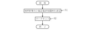
- step S1 the initial impact force and the eccentricity allowable range for the workpiece W are set. That is, the control box of the control device 81 is provided with a display device (operation panel) 79 as shown in FIG. 1, and by operating an operation button (input button) of the display device 79, Enter the impact force and the allowable eccentricity range.
- step S2 the workpiece W is set. That is, the workpiece (workpiece) W is mounted on the workpiece receiver 13 of the turntable 1. At this time, as shown in FIG. 2, the rough guide 18 is roughly centered (implemented).
- the above is the preparation process.
- the initial striking force is arbitrarily set from data in the past centering process according to the type, size, weight, etc. of the work to be centered.
- the eccentricity allowable range is the convergence value. That is, the allowable eccentricity range is a range in which the lathe process and the grinding process performed after the centering process is completed, and can be arbitrarily set according to the type of the workpiece, the lathe process, the grinding process, and the like.
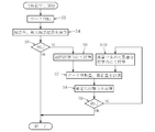
- step S3 the start switch of the operation button (input button) of the display device 79 of the control device 81 is operated.
- start switch of the operation button (input button) of the display device 79 of the control device 81 is operated.
- the workpiece W is rotated (step S3).
- the phase detection sensor 72 displacement measurement sensor
- step S4 the amount of eccentricity and the maximum eccentric position of the workpiece (workpiece) W are calculated.
- step S5 it is determined whether or not the eccentricity obtained in step S4 is within the allowable eccentricity set in step S1 of FIG. If it is within the allowable eccentricity range in step S4, that is, if it is OK, the centering process is finished as it is.
- step S4 If it is not within the allowable range of eccentricity in step S4, that is, if it is NG, the process proceeds to step S6, and the impact force set in step S1 of FIG. 8 is used to strike the maximum eccentric position. After that, the process proceeds to step S7, and the amount of workpiece movement and the amount of workpiece eccentricity due to the previous (first) impact are obtained.
- the relationship between the movement amount X and the striking force F is expressed by the following equation (1).
- step S8 the coefficient k is obtained by substituting the workpiece movement amount and the striking force into this equation (1).
- the optimum striking force is calculated by substituting the calculated k and the work eccentricity after striking determined in Step S7 into X. Is obtained (step S8).
- the process proceeds to step S9, and it is determined whether or not the workpiece eccentric amount after hitting in step S6 is within the allowable eccentric amount range. If the eccentricity is within the allowable range in step S9, that is, if it is OK, the centering process is finished as it is.
- step S9 If it is not within the allowable range of eccentricity in step S9, that is, if it is NG, the process proceeds to step S10 and strikes against the maximum eccentric position by the optimum striking force calculated in step S8. Thereafter, the process proceeds to step S7. For this reason, this centering process is continued until it falls within the allowable eccentricity range. Then, if the eccentric amount is within the allowable range, the centering step is completed.
- the “spring energy” in the equation 2 is expressed by the following equation 3, and the “hammer potential energy” is expressed by the following equation 4.
- the lifting amount in Equation 4 is a dimension from the point at which the weight 27 collides with the workpiece W to the center height position of the weight 27 before the weight 27 is swung down.
- the “spring energy” is the energy of the spring member 28, and the “hammer potential energy” is the potential energy of the weight 27.
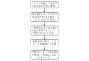
- the centering process of the present invention is performed as shown in FIG. First, an eccentric amount and a maximum eccentric position are obtained (calculated) using Fourier transform. Next, the optimum hitting force F for correcting the eccentricity is calculated. Using a striking device (hammer means 25), striking is performed so that the weight 27 collides with the maximum eccentric position. Thereafter, the workpiece movement amount X ′ due to the collision of the hammer means 25 is measured. The coefficient k is updated from the relationship between the striking force F and the workpiece movement amount X ′.
- the striking force applied to the work is F
- the work movement amount due to the striking force application is X
- the applied striking force Fa
- the movement amount due to this striking force is Xa
- the current eccentric amount is Xb
- the eccentric amount is corrected. Is calculated using Xb / ka, and the impact is applied to the workpiece with this striking force Fb.
- work W rotating through the turntable 1 will be detected, the impact force will be given to the workpiece
- the centering operation to be corrected is performed, and the centering operation is repeated until the eccentricity amount is set to the convergence target value set in advance.
- the impact on the workpiece W by the hammer means 25 is calculated by the control means so as to obtain an optimum impact force for each impact. For this reason, the eccentric amount of the workpiece can be corrected by hitting the workpiece W with the hammer means 25.
- the control means so as to obtain an optimum impact force for each impact.
- the eccentric amount of the workpiece can be corrected by hitting the workpiece W with the hammer means 25.
- centering can be performed until the convergence target value is reached, and high-precision centering can be performed.
- the workpiece W may be a workpiece in a vertical lathe and a horizontal lathe, or a workpiece in a vertical grinder and a horizontal grinder.
- the centering device according to the present invention can be used for a vertical lathe and a horizontal lathe, and can be used for a vertical grinder and a horizontal grinder, thereby improving processing accuracy by the lathe and the grinder. be able to.
- the eccentricity can be corrected even when the workpiece rotation is stopped after detecting the eccentricity of the workpiece.
- the present invention has been described.
- the present invention is not limited to the above-described embodiment, and various modifications are possible.
- the number of the recesses 74 for the proximity sensor can be increased or decreased arbitrarily. If the amount is too small, the measurement accuracy is lowered. If the amount is too large, the workability is inferior.
- the number of the recessed parts 74 can be variously set according to the size of the workpiece W, the rotation speed of the turntable 1, and the like.
- the size of the recess 74 can be variously changed within a range that can be detected by the sensor to be used.
- the size and weight of the weight 27 can be variously changed within a range where an optimum hitting force is obtained.
- the workpiece W is not limited to the inner ring and the outer ring of the bearing, and may be a disk-shaped workpiece that is not a ring-shaped workpiece. Further, the workpiece posture may be vertical or horizontal.
- ⁇ Centering is performed on the ring-shaped workpiece in the lathe process, grinding process, etc., for the ring-shaped structure (ring-shaped workpiece) such as the inner ring and outer ring of the bearing.
- the ring-shaped workpiece may be axially vertical or horizontal.
Landscapes
- Engineering & Computer Science (AREA)
- Mechanical Engineering (AREA)
- Jigs For Machine Tools (AREA)
- Constituent Portions Of Griding Lathes, Driving, Sensing And Control (AREA)
Abstract
装置全体の簡素化を図ることができ、しかも、ワークに対して安定して芯出しを行うことが可能な芯出し装置および芯出し方法を提供する。 ハンマー手段25によるワークWへの衝撃力の付与にてワークWの芯出しを行う。ワークWを回転させるための回転テーブル1と、ワークWに与えた打撃力と、その打撃によるワーク移動量に基づいて、現在のワークWの偏芯量を修正するために次に与える打撃力を演算する制御手段81とを備える。制御手段81にて演算された打撃力でもってハンマー手段25にてワークWを打撃する。
Description
本発明は、芯出し装置および芯出し方法に関する。
軸受の内輪や外輪等のリング状体の構造物(輪状工作物)を製造する場合、輪状工作物に対して、旋盤工程や研削工程を行う。そして、このような工程においては、芯出し装置によって、輪状工作物(ワーク)に対して芯出しを行う必要がある。
従来、大型軸受等の輪状工作物の研削を行う場合は、研削盤の上にワークを仮置きし、熟練した作業者が芯ずれを計測するためのゲージを加工物の外周に当て、加工物を回転させながら1周する間の振れ量を計測する。そして、ハンマーを使って振れの最大位置付近を叩くことで所定の芯出しを行っている。すなわち、このような作業者の人手による芯出し作業では、熟練した作業者がダイヤルゲージの偏芯量を測定し、測定した結果が許容範囲外である場合は、ハンマーなどを用いて加工物をたたき、測定とたたきを繰り返し、許容範囲内になるまでこの作業を行うものである。しかしながら、この作業は、完全に人作業であるため、たたく位置と打力との関係を定量化するのが困難であった。
そこで、近年では、熟練した作業者による芯出しによらず、機械的な自動芯出し装置が 提案されている(特許文献1及び特許文献2)。
特許文献1に記載の芯出し装置は、回転テーブルの回転角度位置を検知する回転角度位置検知器と、被加工物の径方向偏位を検出する径方向偏位検出器と、検知器の検知結果及び検出器の検出結果に基づき偏位すべき被加工物の回転角度及びその修正量を演算する演算制御回路と、修正ヘッドにより、回転中心側に向けて被加工物を押圧する修正機とを備えたものである。
また、特許文献2に記載の芯出し装置は、第1計測手段と、第1位置調整手段と、第2計測手段と、第2位置調整手段と、位置固定手段と、制御手段等を備えるものである。
しかしながら、前記特許文献1に記載のものでは、修正ヘッドの機構の中に偏芯量を測定するためのデジタルスケールを有するものである。このため、装置全体の構造が複雑でコスト高となっていた。しかも、このような装置で大型加工物の芯出しを行う場合、修正ヘッドに大きな荷重がかかる。このため、このヘッドを支えている部材はこの荷重の反力を受ける。したがって、このような部材に偏芯量を測定するケージを取り付けることが精度的に困難であった。
また、特許文献2に記載のものでは、第1計測手段と、第1位置調整手段と、第2計測手段と、第2位置調整手段と、位置固定手段と、制御手段とを備えるものであるので、装置としては、前記特許文献1に記載のものと同等乃至それ以上に構造が複雑となっている。
本発明は、前記課題に鑑みて、装置全体の簡素化を図ることができ、しかも、ワークに対して安定して芯出しを行うことが可能な芯出し装置および芯出し方法を提供する。
本発明の芯出し装置は、ハンマー手段によるワークへの衝撃力付与にてワークの芯出しを行う芯出し装置であって、ワークを回転させるための回転テーブルと、ワークに与えた打撃力と、その打撃によるワーク移動量に基づいて、現在のワークの偏芯量を修正するために次に与える打撃力を演算する制御手段とを備え、この制御手段にて演算された打撃力でもって前記ハンマー手段にてワークを打撃するものである。
本発明の芯出し装置によれば、ハンマー手段によるワークへ衝撃力は、制御手段にて、衝撃毎に最適な打撃力となるように演算される。このため、この制御手段にて演算された最適な打撃力によってハンマー手段がワークを打撃することになって、ワークの偏芯を修正することができる。すなわち、予め打撃力とワークの移動量の関係を手動操作により計測したり、偏芯量に伴った数種の打撃力を定量値として設定したりする必要がなく、ワークの種類や回転テーブルの表面状態の変化によりワークや回転テーブルの摩擦力が変化しても、常に都度演算された最適な打撃力により、効率的な芯出しを行うことができる。
前記制御手段は、ワークの回転角位相を検出する回転角位相検出センサと、ワークの変位を検出する変位センサとを備え、位相検出センサにて検出した回転角位相と、変位センサにて検出した変位とに基づいて、ワークの偏芯量と最大偏芯位置を求め、ワークに付与した打撃力に基づいて偏芯量を修正するための打撃力を演算し、その演算された打撃力によって最大偏芯位置に打撃を付与するものである。
位相検出センサにて検出した回転角位相と変位センサにて検出した変位とに基づいて、フーリエ変換を実施し、回転1次成分の変位データを分離することで偏芯量と最大偏芯位置を求めることができる。
前記制御手段は、ワークに付与した打撃力と、その打撃力によるワーク移動量に基づいて、その打撃においてもワークが偏芯していれば、次に付与する打撃力を演算して、その演算した打撃力によって最大偏芯位置に打撃を付与するようにするのが好ましい。このような制御を行うことによって、1回の打撃で芯出しできないときであっても、順次打撃していくことによって芯出しすることができる。
ワークに付与する打撃力をFとし、その打撃力付与によるワーク移動量をXとし、ワーク移動量と打撃力との理論上の関係を、X=kF(kは定数)とし、ワークに付与した打撃力がFaであり、この打撃力の付与による移動量がXaであるときに、Xa/Fa=kaを演算し、現在の偏芯量をXbとし、その偏芯量を修正するための打撃力をFbとして、このFbをXb/kaでもって演算し、この打撃力Fbでワークに衝撃力を付与するようにできる。
前記ワークが縦型旋盤や横型旋盤における加工物であっても、ワークが縦型研削盤や横型研削盤における加工物であってもよい。また、ワークの偏芯量を検出した後に、ワーク回転を停止させた状態でも偏芯量を修正することができる。
本発明の芯出し方法は、ハンマー手段によるワークへの衝撃力付与にてワークの芯出しを行う芯出し方法であって、ハンマー手段にてワークに衝撃力を付与し、その打撃によるワーク移動量に基づいて次に与える打撃力を演算し、この演算した打撃力にてワークを打撃してワークの偏芯を修正する芯出し動作を行い、偏芯量が予め設定された収束目標値まで前記芯出し動作を繰り返すものである。
本発明の芯出し装置では、衝撃毎に最適な打撃力となるように演算され、安定した芯出し作業が可能となる。特に、打撃力とワーク移動量との関係を手動操作にて計測する必要はなく、データシートの入力が不要となる。
最大偏芯位置に対して、偏芯量を修正するための打撃力にてワークを打撃するものでは、精度の良い芯出しを行うことができる。フーリエ変換を実施することで、ワーク形状に依存せず偏芯量と最大偏芯位置を正確に求めることができる。
1回の打撃で芯出しできないときであっても、順次打撃していくことによって芯出しすることができるものでは、複数回の打撃によって、高精度な芯出し作業を行うことができる。Xa/Fa=kaを演算する演算方法では、偏芯量を修正するための打撃力を安定して正確に求めることができる。
芯出し装置が縦型旋盤や横型旋盤に用いられたり、縦型研削盤や横型研削盤に用いられたりすることができ、旋盤や研削盤による加工精度の向上を図ることができる。
本発明の方法によれば、収束目標値になるまで芯出しすることができ、高精度の芯出しを行うことができる。
以下本発明の実施の形態を図1~図9に基づいて説明する。
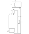
図1は本発明に係る芯出し装置を示し、この芯出し装置は、ワークWが載置される回転テーブル1と、この回転テーブル1をその軸心廻りに回転させる駆動機構2(図2等参照)と、回転テーブル1上のワークW(ベアリングの内輪や外輪等の輪状加工物)へ衝撃力を付与する衝撃力付与構造3とを備える。
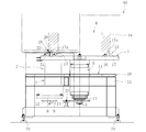
駆動機構2は、図2~図4に示すように、回転テーブル1の中心軸5をその軸心を中心に回転自在に支持する軸受構造体6と、駆動用モータ7と、この駆動用モータ7の出力軸8と前記中心軸5とを連動連結する連動部材9とを備える。連動部材9は、回転テーブル1の中心軸5に装着されたスプロケット11と、駆動用モータ7の出力軸8に装着されたスプロケット12と、これらスプロケット11,12に掛け回されるチェーン(図示省略)とを備える。軸受構造体6と駆動用モータ7とは基台10に支持されている。基台10は、基板14と、この基板14を支持する脚体15とを備える。また、脚体15のコーナ部下端にアジャスタ19が付設されている。
このため、駆動用モータ7が駆動すれば、その出力軸8の回転が連動部材9を介して中心軸5に伝達され、回転テーブル1がその軸心廻りに回転する。なお、スプロケット11,12間には、チェーンに張力を付与する張力付与機構23が設けられている。すなわち、張力付与機構23は回転盤24を有し、この回転盤24にてチェーンを外側から押圧する。これによって、チェーンに張力を付与する。
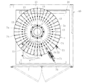
回転テーブル1には、複数のワーク受け13が周方向に沿って所定ピッチで配設されている。このワーク受け13は、回転テーブル1に固定される水平部16と、この水平部16の外径側から立設される鉛直部17とからなり、この鉛直部17の上端面17aにてワークWを受けることになる。
また、ワーク受け13の外周側に、周方向に沿って所定ピッチに複数個のラフガイド18が設けられている。ラフガイド18は、ワークWの下端面と外径面とのコーナ部を案内する案内面20を有する。すなわち、ラフガイド18は、回転テーブル1に固定される水平部21と、この水平部21の内径側から立設される鉛直部22とを備え、この鉛直部22の上部内径側にテーパ面が設けられ、このテーパ面が前記案内面20を形成する。ワークWを回転テーブル1に載置したときに、ワークWの芯ずれ量(偏芯量)が過大にならないように、平面的に見て、ワークWの外径面よりも、数ミリ程度に大きい円弧上にラフガイド18の案内面20を配置する。
衝撃力付与構造3は、図6に示すように、ワークWに衝撃力を付与するハンマー手段25を備える。ハンマー手段25は、アーム26と、このアーム26の先端に付設される錘27とを備える。アーム26は、この支点Aを中心に矢印B、Cのように揺動する。この場合、支点Aから錘27の中心Oまでの長さをL2とし、支点Aから反錘側の端Eまでの長さをL1としたときに、L2>L1となる。端Eにはバネ部材28が付設されている。自由状態では、アーム26を鉛直線上に配置するものである。
このため、このバネ部材28がこの弾性力に抗して、矢印B方向に揺動すれば、バネ部材28がこの図6に示すように、その軸方向に延びた状態となる。この延びた状態から、支点Aを中心に矢印B方向の揺動力が解除されれば、バネ部材28の弾性力によって、アーム26はその支点Aを中心に矢印C方向に揺動する。これによって、錘27がこの重力とバネ部材28の弾性力によって、ワークWに衝突する。
この場合、図示省略するが、後述するように、最適な打撃力をワークに与えるための寸法だけ、バネ部材28を延ばした状態の維持を可能な維持機構(例えば、シリンダ機構、ボールねじ機構等を備えたもの)を備える。
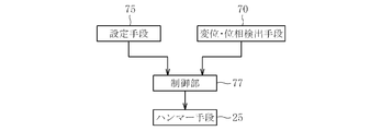
この装置は、打撃位置及び打撃力が自動的に設定されて、芯出し動作が行われる。このため、図1に示すように制御装置(制御手段)81が設けられる。制御装置81としては、図7に示すように、ワークWの偏芯量の収束値を設定する設定手段75と、ワークWの変位量・位相を検出する変位・位相検出手段70と、制御部77とを備える。
設定手段75にて設定される収束値は、許容できるワークWの芯ずれの収束値であって、本発明では、この収束値以内になるまで芯出し動作が行われる。変位・位相検出手段70は、図5に示すように、ワークWの偏芯大きさを検出する変位センサ71と、前記テーブル1の回転角位相を検出する位相検出センサ72とを備える。
この変位センサ71は、ワークの偏芯量を検出することができればよいので、非接触式であっても、接触式であってもよく種々のタイプのものを使用することができる。
位相検出センサ72は、この場合、近接センサ73を使用しているがロータリーエンコーダを設置してもよい。近接センサとは、リミットスイッチやマイクロスイッチなどの機械式スイッチにかわるもので非接触で検出物体が近づいたことを検出するセンサである。おもな近接センサは動作原理の違いにより、次の3つのタイプに大別される。電磁誘導を利用した高周波発振型、磁石を用いた磁気型、静電容量の変化を利用した静電容量型の3つである。
この実施形態では、回転テーブル1の外周面1aに周方向に沿って所定ピッチ(定ピッチ)に複数の凹部(ドグ)74を設け、この凹部(ドグ)74を近接センサ73にて検出するようにしている。すなわち、凹部(ドグ)74を近接センサ73にて検出することによって、テーブル1が1周する時のパルス数をカウントするようにしている。
制御部77は、変位センサ71で得られた変位量とテーブル1の回転角位相を検出する近接センサ73との情報からフーリエ変換を行い、回転一次成分を分離することで偏芯量と最大偏芯位置(回転角位相)を演算する。また、予め設定した収束値以内に偏芯量が収まるまで芯出し指令を出す。制御部77の制御は,PLC(Programable Logic controller)等を用いて行われる。
次に、前記のように構成された芯出し装置を使用した芯出し方法を図8及び図9等を用いて説明する。まず、図8に示す芯出し準備工程を行う。すなわち、ステップS1に示すように、このワークWに対する初回打撃力と偏芯量許容範囲を設定する。すなわち、制御装置81の制御ボックスには、図1に示すような表示器(操作盤)79が設けられ、この表示器79の操作ボタン(入力ボタン)を操作することにより、制御装置81に初回打撃力と偏芯量許容範囲を入力する。次に、ステップS2に示すように、ワークWをセットする。すなわち、ワーク(被加工物)Wを回転テーブル1のワーク受け13上に搭載する。この際、図2に示すように、ラフガイド18に大まかな芯出しを行う(実施する)。以上が準備工程である。なお、初回打撃力は、芯出しするワークの種類、大きさ、及び重さ等に応じて過去の芯出し工程におけるデータから任意に設定される。また、偏芯量許容範囲とは、前記収束値である。すなわち、偏芯量許容範囲はこの芯出し工程終了後に行う旋盤工程や研削工程を行うことが可能範囲であり、ワークの種類や旋盤工程や研削工程等に応じて任意に設定できる。
次に図9に示す芯出し工程を行う。この工程では、自動スタートを指令してこの工程を開始する。すなわち、制御装置81の表示器79の操作ボタン(入力ボタン)のスタートスイッチを操作する。この開始(スタート)によって、ワークWを回転させる(ステップS3)。その後、位相検出センサ72(変位計測用センサ)をワーク(被加工物)Wに接触させ変位センサ71にて得られるワーク変位データと、位相検出センサ72にて得られるワーク位相データを基に、ステップS4に示すように、ワーク(被加工物)Wの偏芯量及び最大偏芯位置を演算する。
この場合、ワーク変位データとワーク位相データを基に、フーリエ変換を実施し、回転1次成分の変位データを分離することで偏芯量及び最大偏芯位置を求める。次にステップS5へ移行して、ステップS4で求めた偏芯量が、前記図8のステップS1で設定した偏芯量許容範囲内か否かを判断する。ステップS4で偏芯量許容範囲内であれば、すなわち、OKならばこのまま芯出し工程が終了する。
ステップS4で偏芯量許容範囲内でなければ、すなわち、NGならば、ステップS6へ移行して、前記図8のステップS1で設定した打撃力で、最大偏芯位置に対して打撃する。その後は、ステップS7へ移行して、前回(初回)の打撃によるワーク移動量とワーク偏芯量を求める。ところで、移動量Xと打撃力Fとの関係は、次の数1によって表される。

このため、この数1の式にワーク移動量と打撃力を代入して係数kを求める。次に、移動量Xと打撃力Fの関係式(前記数1)を利用して、求めたkとステップS7で求めた打撃後のワーク偏芯量をXに代入することで、最適打撃力を求める(ステップS8)。その後、ステップS9へ移行してステップS6で打撃した後のワーク偏芯量が偏芯量許容範囲内であるか否かを判断する。ステップS9で偏芯量許容範囲内であれば、すなわち、OKならばこのまま芯出し工程が終了する。ステップS9で偏芯量許容範囲内でなければ、すなわち、NGならば、ステップS10へ移行して、ステップS8で演算した最適な打撃力によって最大偏芯位置に対して打撃する。その後は、ステップS7へ移行する。このため、偏芯量許容範囲内に入るまで、この芯出し工程が継続される。そして、偏芯量許容範囲内に入れば、芯出し工程が終了する。
ところで、図6に示すハンマー手段25では、支点Aを中心としたアーム26の揺動によって錘27がワークWに衝突するものである。このため、このアーム26の鉛直軸と成す角度(以下、ハンマー角度と呼ぶ場合がある)θ(0°~40°)とした場合、打撃力は次の数2で表される。

数2における「バネのエネルギー」は次の数3で表され、「ハンマーの位置エネルギー」は次の数4で表される。また、ハンマー角度θが0°~40°である場合、次の数5で示される関係がある。このため、前記数2の関係を導き出せる。なお、数4における持ち上量は、図6に示すように、錘27がワークWに衝突する点から、錘27が振り下ろされる前の錘27の中心高さ位置までの寸法である。また、前記「バネのエネルギー」は、バネ部材28のエネルギーであり、「ハンマーの位置エネルギー」は錘27の位置エネルギーである。



このように、本発明の芯出し工程は、図10に示すような工程を行うことになる。まず、フーリエ変換を用いて偏芯量と最大偏芯位置を求める(演算する)。次に、偏芯量を修正する為の最適な打撃力Fを演算する。打撃装置(ハンマー手段25)を用いて最大偏芯位置に錘27が衝突するように打撃を実施する。その後、ハンマー手段25が衝突したことによるワーク移動量X´を計測する。打撃力Fとワーク移動量X´の関係から係数kを更新する。
すなわち、ワークに付与する打撃力をFとし、その打撃力付与によるワーク移動量をXとし、ワーク移動量と打撃力との理論上の関係を、X=kF(kは定数)とし、ワークに付与した打撃力をFaであり、この打撃力の付与による移動量をXaであるときに、Xa/Fa=kaを演算し、現在の偏芯量をXbとし、その偏芯量を修正するための打撃力をFbとして、このFbをXb/kaでもって演算し、この打撃力Fbでワークに衝撃を付与するようにできる。
このため、前記芯出し装置を用いれば、回転テーブル1を介して回転しているワークWの偏芯量を検出し、ハンマー手段25にてワークWへ衝撃力を付与して前記偏芯量を修正する芯出し動作を行い、偏芯量が予め設定された収束目標値まで芯出し動作を繰り返すことになる。
本発明では、ハンマー手段25によるワークWへ衝撃は、制御手段にて、衝撃毎に最適な打撃力となるように演算される。このため、ハンマー手段25のワークWへの打撃にて、ワークの偏芯量を修正することができる。すなわち、予め打撃力とワークWの移動量の関係を手動操作により計測したり、偏芯量に伴った数種の打撃力を定量値として設定したりする必要がなく、ワークWの種類や回転テーブル1の表面状態の変化によりワークWや回転テーブル1の摩擦力が変化しても、常に都度演算された最適な打撃力により、効率的な芯出しを行うことができる。安定した芯出し作業が可能となる。特に、打撃力とワーク移動量との関係を手動操作にて計測する必要はなく、データシートの入力が不要となる利点がある。
最大偏芯位置に対して、偏芯量を修正するための打撃力にてワークWを打撃するものでは、精度の良い芯出しを行うことができる。フーリエ変換を実施するものでは、偏芯量と最大偏芯位置を安定して正確に求め、しかも、測定時間の短縮を図ることができる。
1回の打撃で芯出しできないときであっても、順次打撃していくことによって芯出しすることができるものでは、複数回の打撃によって、高精度な芯出し作業を行うことができる。Xa/Fa=kaを演算する演算方法では、偏芯量を修正するための打撃力を安定して正確に求めることができる。
本発明の方法によれば、収束目標値になるまで芯出しすることができ、高精度の芯出しを行うことができる。
ところで、ワークWが縦型旋盤及び横型旋盤における加工物であったり、縦型研削盤及び横型研削盤における加工物であったりする。このように、本発明にかかる芯出し装置は、縦型旋盤及び横型旋盤に用いたり、縦型研削盤及び横型研削盤に用いたりすることができ、旋盤や研削盤による加工精度の向上を図ることができる。また、ワークの偏芯量を検出した後に、ワーク回転を停止させた状態でも偏芯量を修正することができる。
以上、本発明の実施形態につき説明したが、本発明は前記実施形態に限定されることなく種々の変形が可能であって、例えば、近接センサ用の凹部74の数の増減も任意であるが、少なすぎると、測定精度が低下し、多すぎると、加工性に劣ることになる。このため、ワークWの大きさ、回転テーブル1の回転速度等に応じて、凹部74の数を種々設定できる。また、凹部74の大きさとしては、使用するセンサが検出可能な範囲で種々変更することができる。錘27の大きさや重さも、最適打力を得る範囲で種々変更することができる。なお、ワークWとしては、ベアリングの内輪や外輪に限らず、輪状加工物ではない円盤状加工物等であってもよい。また、ワーク姿勢は、軸垂直であっても軸水平であってもよい。
軸受の内輪や外輪等のリング状体の構造物(輪状工作物)に対して、旋盤工程や研削工程等の工程において、輪状工作物に対して芯出しを行う。芯出しを行う際に、輪状工作物が軸垂直であっても軸水平であってもよい。
1 回転テーブル
25 ハンマー手段
70 変位検出手段
71 変位センサ
72 位相検出センサ
81 制御装置(制御手段)
W ワーク
25 ハンマー手段
70 変位検出手段
71 変位センサ
72 位相検出センサ
81 制御装置(制御手段)
W ワーク
Claims (11)
- ハンマー手段によるワークへの衝撃力付与にてワークの芯出しを行う芯出し装置であって、
ワークを回転させるための回転テーブルと、
ワークに与えた打撃力と、その打撃によるワーク移動量に基づいて、現在のワークの偏芯量を修正するために次に与える打撃力を演算する制御手段とを備え、
この制御手段にて演算された打撃力でもって前記ハンマー手段にてワークを打撃することを特徴とする芯出し装置。 - 前記制御手段は、ワークの回転角位相を検出する回転角位相検出センサと、ワークの変位を検出する変位センサとを備え、位相検出センサにて検出した回転角位相と、変位センサにて検出した変位とに基づいて、ワークの偏芯量と最大偏芯位置を求め、ワークに付与した打撃力に基づいて偏芯量を修正するための打撃力を演算し、その演算された打撃力によって最大偏芯位置に打撃を付与することを特徴とする請求項1に記載の芯出し装置。
- 位相検出センサにて検出した回転角位相と変位センサにて検出した変位とに基づいて、フーリエ変換を実施し、回転1次成分の変位データを分離することで偏芯量と最大偏芯位置を求めることを特徴とする請求項2に記載の芯出し装置。
- 前記制御手段は、ワークに付与した打撃力と、その打撃力によるワーク移動量に基づいて、その打撃においてもワークが偏芯していれば、次に付与する打撃力を演算して、その演算した打撃力によって最大偏芯位置に打撃を付与することを特徴とする請求項1~請求項3のいずれか1項に記載の芯出し装置。
- ワークに付与する打撃力をFとし、その打撃力付与によるワーク移動量をXとし、ワーク移動量と打撃力との理論上の関係を、X=kF(kは定数)とし、ワークに付与した打撃力がFaであり、この打撃力の付与による移動量がXaであるときに、Xa/Fa=kaを演算し、現在の偏芯量をXbとし、その偏芯量を修正するための打撃力をFbとして、このFbをXb/kaでもって演算し、この打撃力Fbでワークに衝撃力を付与することを特徴とする請求項4に記載の芯出し装置。
- 前記ワークが縦型旋盤における加工物であることを特徴とする請求項1~請求項5のいずれか1項に記載の芯出し装置。
- 前記ワークが横型旋盤における加工物であることを特徴とする請求項1~請求項5のいずれか1項に記載の芯出し装置。
- 前記ワークが縦型研削盤における加工物であることを特徴とする請求項1~請求項5のいずれか1項に記載の芯出し装置。
- 前記ワークが横型研削盤における加工物であることを特徴とする請求項1~請求項5のいずれか1項に記載の芯出し装置。
- ワークの偏芯量を検出した後に、ワーク回転を停止させた状態でも偏芯量を修正することができることを特徴とする請求項1~請求項9のいずれか1項に記載の芯出し装置。
- ハンマー手段によるワークへの衝撃力付与にてワークの芯出しを行う芯出し方法であって、
ハンマー手段にてワークに衝撃力を付与し、その打撃によるワーク移動量に基づいて次に与える打撃力を演算し、この演算した打撃力にてワークを打撃してワークの偏芯を修正する芯出し動作を行い、偏芯量が予め設定された収束目標値まで前記芯出し動作を繰り返すことを特徴とする芯出し方法。
Applications Claiming Priority (2)
| Application Number | Priority Date | Filing Date | Title |
|---|---|---|---|
| JP2010097163A JP2011224730A (ja) | 2010-04-20 | 2010-04-20 | 芯出し装置および芯出し方法 |
| JP2010-097163 | 2010-04-20 |
Publications (1)
| Publication Number | Publication Date |
|---|---|
| WO2011132517A1 true WO2011132517A1 (ja) | 2011-10-27 |
Family
ID=44834051
Family Applications (1)
| Application Number | Title | Priority Date | Filing Date |
|---|---|---|---|
| PCT/JP2011/058384 Ceased WO2011132517A1 (ja) | 2010-04-20 | 2011-04-01 | 芯出し装置および芯出し方法 |
Country Status (2)
| Country | Link |
|---|---|
| JP (1) | JP2011224730A (ja) |
| WO (1) | WO2011132517A1 (ja) |
Families Citing this family (6)
| Publication number | Priority date | Publication date | Assignee | Title |
|---|---|---|---|---|
| JP6162612B2 (ja) * | 2014-01-15 | 2017-07-12 | ファナック株式会社 | 射出成形機の可動部の異常検出装置 |
| JP6481477B2 (ja) * | 2015-04-16 | 2019-03-13 | 日本精工株式会社 | ワークの自動芯出し装置、該自動芯出し装置に使用される可動装置の位置決め方法、生産機械、及び軸受の製造方法 |
| JP6496209B2 (ja) * | 2015-08-05 | 2019-04-03 | オークマ株式会社 | 回転位置検出器のロータ芯出し装置 |
| KR20210133025A (ko) * | 2020-04-28 | 2021-11-05 | 한국기계연구원 | 충격 액튜에이터 및 이를 이용한 편심량 자동 보정 시스템 및 방법 |
| CN111590367B (zh) * | 2020-06-02 | 2021-07-16 | 大连理工大学 | 一种回转类零件检测与找正一体化装置及方法 |
| JP2024055588A (ja) * | 2022-10-07 | 2024-04-18 | 芝浦機械株式会社 | ワークの芯出し方法及び工作機械 |
Citations (1)
| Publication number | Priority date | Publication date | Assignee | Title |
|---|---|---|---|---|
| JP2010082745A (ja) * | 2008-09-30 | 2010-04-15 | Ntn Corp | 芯出し装置および芯出し方法 |
Family Cites Families (1)
| Publication number | Priority date | Publication date | Assignee | Title |
|---|---|---|---|---|
| US4926337A (en) * | 1988-07-13 | 1990-05-15 | Bryant Grinder Corporation | Automatic workpart centering mechanism for a chuck |
-
2010
- 2010-04-20 JP JP2010097163A patent/JP2011224730A/ja active Pending
-
2011
- 2011-04-01 WO PCT/JP2011/058384 patent/WO2011132517A1/ja not_active Ceased
Patent Citations (1)
| Publication number | Priority date | Publication date | Assignee | Title |
|---|---|---|---|---|
| JP2010082745A (ja) * | 2008-09-30 | 2010-04-15 | Ntn Corp | 芯出し装置および芯出し方法 |
Also Published As
| Publication number | Publication date |
|---|---|
| JP2011224730A (ja) | 2011-11-10 |
Similar Documents
| Publication | Publication Date | Title |
|---|---|---|
| CN102164706B (zh) | 定心装置及定心方法 | |
| WO2011132517A1 (ja) | 芯出し装置および芯出し方法 | |
| US9511464B2 (en) | Adjustment mechanism for rotation runout and dynamic balance of rotating tool | |
| JP6316858B2 (ja) | モータの軸精度自動測定装置 | |
| JP6208844B2 (ja) | 測定対象物の形状輪郭を割り出す方法 | |
| KR101433854B1 (ko) | 연주기 세그먼트 롤 베어링 틈새 검사장치 | |
| US9303968B2 (en) | Lever type measuring machine | |
| JP6542629B2 (ja) | 加工ツールの位置決め装置及び位置決め方法 | |
| CN210550116U (zh) | 一种智能环抛机床 | |
| CN103994717B (zh) | 齿轮光学测量装置及检测方法 | |
| CN106568387A (zh) | 一种大长径比空心薄壁细长轴精密检测设备及检测方法 | |
| KR20130105417A (ko) | 렌즈의 심 어긋남 검출기 및 렌즈 심취기 | |
| CN109648398A (zh) | 一种零件尺寸在线检测装置及其检测方法 | |
| JP5501998B2 (ja) | 検査装置および検査方法 | |
| CN106216440A (zh) | 一种航空发动机主轴智能检测校形装置 | |
| JP2011245608A (ja) | 偏芯ワークの位相出し方法およびその装置、ならびに、それらを用いた円筒研削盤へのワーク供給方法およびその装置 | |
| JP6496924B2 (ja) | ワーク円筒部の形状測定方法および形状測定装置 | |
| JP2010142933A (ja) | 芯出し装置および芯出し方法 | |
| US20230330797A1 (en) | Centering tool, centering device, machine tool, method of centering circular workpiece, circular workpiece manufacturing method, ring member manufacturing method, bearing manufacturing method, machine manufacturing method, vehicle manufacturing method, and program | |
| JP7401551B2 (ja) | ロボットアームの装置と調整方法 | |
| CN103522127A (zh) | 一种用于回转式曲线轮廓加工的在机测量装置及方法 | |
| CN101539392B (zh) | 校正顶尖跳动的方法 | |
| CN115224888B (zh) | 一种散片定子自动振动机结构及生产工艺 | |
| CN105127242B (zh) | 一种轴类零件弯曲校正方法 | |
| JP2010082745A (ja) | 芯出し装置および芯出し方法 |
Legal Events
| Date | Code | Title | Description |
|---|---|---|---|
| 121 | Ep: the epo has been informed by wipo that ep was designated in this application |
Ref document number: 11771854 Country of ref document: EP Kind code of ref document: A1 |
|
| NENP | Non-entry into the national phase |
Ref country code: DE |
|
| 122 | Ep: pct application non-entry in european phase |
Ref document number: 11771854 Country of ref document: EP Kind code of ref document: A1 |