WO2011132370A1 - 炉心溶融物保持構造体 - Google Patents
炉心溶融物保持構造体 Download PDFInfo
- Publication number
- WO2011132370A1 WO2011132370A1 PCT/JP2011/002032 JP2011002032W WO2011132370A1 WO 2011132370 A1 WO2011132370 A1 WO 2011132370A1 JP 2011002032 W JP2011002032 W JP 2011002032W WO 2011132370 A1 WO2011132370 A1 WO 2011132370A1
- Authority
- WO
- WIPO (PCT)
- Prior art keywords
- support plate
- core
- lower support
- reactor vessel
- heat
- Prior art date
- Legal status (The legal status is an assumption and is not a legal conclusion. Google has not performed a legal analysis and makes no representation as to the accuracy of the status listed.)
- Ceased
Links
Images




Classifications
-
- G—PHYSICS
- G21—NUCLEAR PHYSICS; NUCLEAR ENGINEERING
- G21C—NUCLEAR REACTORS
- G21C13/00—Pressure vessels; Containment vessels; Containment in general
-
- G—PHYSICS
- G21—NUCLEAR PHYSICS; NUCLEAR ENGINEERING
- G21C—NUCLEAR REACTORS
- G21C5/00—Moderator or core structure; Selection of materials for use as moderator
- G21C5/02—Details
- G21C5/10—Means for supporting the complete structure
-
- G—PHYSICS
- G21—NUCLEAR PHYSICS; NUCLEAR ENGINEERING
- G21C—NUCLEAR REACTORS
- G21C9/00—Emergency protection arrangements structurally associated with the reactor, e.g. safety valves provided with pressure equalisation devices
- G21C9/016—Core catchers
-
- Y—GENERAL TAGGING OF NEW TECHNOLOGICAL DEVELOPMENTS; GENERAL TAGGING OF CROSS-SECTIONAL TECHNOLOGIES SPANNING OVER SEVERAL SECTIONS OF THE IPC; TECHNICAL SUBJECTS COVERED BY FORMER USPC CROSS-REFERENCE ART COLLECTIONS [XRACs] AND DIGESTS
- Y02—TECHNOLOGIES OR APPLICATIONS FOR MITIGATION OR ADAPTATION AGAINST CLIMATE CHANGE
- Y02E—REDUCTION OF GREENHOUSE GAS [GHG] EMISSIONS, RELATED TO ENERGY GENERATION, TRANSMISSION OR DISTRIBUTION
- Y02E30/00—Energy generation of nuclear origin
- Y02E30/30—Nuclear fission reactors
Definitions
- the present invention relates to a core melt holding structure that holds a melting core in a reactor vessel containing the core.
- the hot core melt melts into the lower part of the reactor pressure vessel, and further melts through the reactor pressure vessel lower mirror and falls onto the floor in the containment vessel.
- the core melt heats the concrete stretched on the containment floor, reacts with the concrete when the contact surface becomes hot, generates a large amount of noncondensable gases such as carbon dioxide and hydrogen, and melts and erodes the concrete.
- the generated non-condensable gas increases the pressure in the containment vessel and may damage the reactor containment vessel.
- the containment boundary may be damaged by melting and erosion of concrete.
- a typical method for holding and cooling the core melt in the reactor pressure vessel is a technique called IVR (In-Vessel Retention).
- IVR In-Vessel Retention
- the reactor vessel is externally flooded with cooling water, the heat transferred from the core melt is removed by boiling water transfer of the cooling water, the generated steam is cooled and condensed in the containment vessel, and the condensed water is condensed into the reactor. Return to around container.
- the core melt and the reactor vessel that have melted down to the lower part of the reactor vessel are cooled to prevent the reactor vessel from being damaged and the core melt from flowing out into the containment vessel.
- the problem is the high heat flux generated in the metal layer formed in the molten core deposited at the bottom of the reactor vessel.
- the oxide and metal constituting the molten core are separated and deposited in layers.
- the heat generated in the molten core concentrates on the metal layer with relatively high thermal conductivity, so the heat flux at the position where the metal layer is formed can increase significantly. There is sex. When the high heat flux at the position where the metal layer is formed exceeds the cooling performance by the cooling water, the reactor vessel is damaged.
- the position where the metal layer is formed when laying the heat-resistant material around the position where the metal layer is formed to prevent the reactor pressure vessel from being damaged by the high heat flux generated at the position where the metal layer is formed are highly uncertain and difficult to fully predict.
- the amount of metal contained in the molten core is extremely small, even if fine particles are mixed in the cooling water, a heat flux exceeding the effect of improving the cooling performance due to this occurs at the position where the metal layer is formed.
- the reactor pressure vessel may be damaged.
- an object of the present invention is to reduce the possibility of the reactor vessel being damaged by the high heat flux at the position where the metal layer is formed in the reactor vessel when the core is melted.
- the present invention provides a reactor core holding structure in a core melt holding structure, and a flow path hole provided below the core and supporting the core and penetrating vertically.
- a lower support plate formed, a lower support plate support fixed to the reactor vessel and supporting the lower support plate, a heat insulating spacer, and fixed to the lower support plate support through the heat insulating spacer.
- a heat path structure having a support plate contact portion in contact with the lower support plate and a height direction transmission portion extending downward from the support plate contact portion and having a thermal conductivity higher than that of the heat insulating spacer, To do.
- the present invention also provides a reactor vessel that houses the core, and a lower support plate that is provided below the core and has flow passage holes that support the core and penetrate vertically.
- a lower support plate support that is fixed to the reactor vessel and supports the lower support plate, a plurality of height direction transmission portions that extend downward from the flow path holes, and a plurality of surfaces in contact with the upper surface of the lower support plate
- a heat path structure including a horizontal direction transmission part that connects between the height direction transmission parts.
- the present invention also provides a reactor vessel that houses the core, and a lower support plate that is provided below the core and has flow passage holes that support the core and penetrate vertically. And a weir standing up from the upper surface of the support plate and surrounding the channel hole, and a lower support plate support fixed to the reactor vessel and supporting the lower support plate.
- the possibility that the reactor vessel is damaged by the high heat flux at the position where the metal layer is formed in the reactor vessel can be reduced.
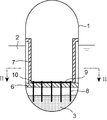
- FIG. 3 is a sectional view taken along the line II in FIG. 2 showing an elevated cross section of the nuclear reactor in the first embodiment of the core melt holding structure according to the present invention.
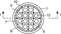
- FIG. 2 is a plan sectional view taken along the line II-II in FIG. It is an elevation sectional view near the heat insulation spacer in a 1st embodiment of the core melt maintenance structure concerning the present invention. It is the perspective view which extracted a part of reticulated heat path, heat insulation spacer, and a fastening bolt in a 1st embodiment of a core melt maintenance structure concerning the present invention. It is an elevation sectional view of a nuclear reactor using a 2nd embodiment of a core melt maintenance structure concerning the present invention.
- FIG. 5 is a vertical sectional view of a nuclear reactor using a third embodiment of a core melt holding structure according to the present invention.
- FIG. 10 is an elevational sectional view of the vicinity of a joint portion between a mesh heat path and a lower support plate support in a fourth embodiment of a core melt holding structure according to the present invention.
- FIG. 10 is an elevational sectional view of a vicinity of a joint portion between a mesh heat path and a lower support plate support in a fifth embodiment of a core melt holding structure according to the present invention.
- It is a plane sectional view of a nuclear reactor vessel in a sixth embodiment of a core melt holding structure according to the present invention.
- 1 is a plan sectional view of a nuclear reactor vessel in a first embodiment of a core melt holding structure according to the present invention.
- 1 is a vertical sectional view of a reactor vessel in a first embodiment of a core melt holding structure according to the present invention.
- FIG. 1 is a sectional view taken along the line II in FIG. 2 showing an elevational section of a nuclear reactor in a first embodiment of a core melt holding structure according to the present invention.
- 2 is a cross-sectional view taken along the line II-II in FIG.
- the core melt holding structure includes a nuclear reactor vessel 1 that houses the core, a lower support plate 6, a lower support plate support 7, a heat insulating spacer 10, a height direction heat path 8, and a reticulated heat path 9.
- a heat path structure and holds the melting core in the reactor vessel 1.
- the nuclear reactor vessel 1 is formed by closing both ends of a cylinder extending in the vertical direction with a hemispherical head. During normal operation, the heat generated in the core in the reactor vessel 1 heats the cooling water to generate steam, and the generated steam rotates a turbine (not shown) to generate power.
- the lower support plate 6 is provided below the core in the reactor vessel 1 and supports the core.
- the lower support plate 6 is a plate extending in the horizontal direction, and a plurality of flow passage holes 15 penetrating vertically are formed.
- the lower support plate support 7 extends in the vertical direction from the outer periphery of the lower support plate 6 in the reactor vessel 1 and extends toward the inner surface of the reactor vessel 1 at the upper end.
- the lower support plate support 7 is fixed to the nuclear reactor vessel 1 and supports the lower support plate 6.
- the heat path structure is provided in the nuclear reactor vessel 1 and includes a support plate contact portion and a height direction transmission portion extending downward from the support plate contact portion.
- the support plate contact portion is a reticulated heat path 9, which is a heat path that transfers heat in the horizontal direction.
- the height direction transmission part is the height direction heat path 8 and is a heat path that transfers heat in the height direction.
- the mesh heat path 9 is formed in a mesh pattern on the upper surface of the lower support plate 6 and is in contact with the upper surface of the lower support plate 6.
- the net-like heat path 9 is fixed to the lower support plate support 7 via a heat insulating spacer 10.
- the height direction heat path 8 extends downward from the mesh heat path 9 through the lower support plate 6.
- the height direction heat path 8 is connected to the mesh heat path 9.
- the mesh heat path 9 and the height direction heat path 8 are formed of a material having a high melting point and high thermal conductivity, such as tungsten.
- a thin plate having the same shape as the lower support plate 6 may be used.
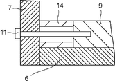
- FIG. 3 is an elevational sectional view in the vicinity of the heat insulating spacer in the present embodiment.
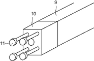
- FIG. 4 is a perspective view of a part of the mesh heat path, the heat insulating spacer, and the fastening bolt extracted in the present embodiment.
- the mesh heat path 9 in contact with the upper surface of the lower support plate 6 is fixed to the heat insulating spacer 10 by fastening bolts 11.
- the heat insulating spacer 10 is fixed to the support plate support 7 by another fastening bolt 11.
- the fastening bolt 11 that joins the reticulated heat path 9 and the heat insulating spacer 10 is kept out of contact with the support plate support 7.
- the heat insulating spacer 10 is formed of an oxide such as alumina having a high melting point.
- the height heat path directly contacts the core melt 3
- the heat of the core melt 3 is transmitted to the vertical heat path 8.
- the heat transferred to the height direction heat path 8 is transferred to the mesh heat path 9 and the lower support plate 6 by heat conduction. As a result, the lower support plate 6 is melted and dropped into the core melt 3.
- the oxide and metal constituting the molten core may be separated and deposited in layers.
- the heat generated in the molten core concentrates on the metal layer with relatively high thermal conductivity, so the heat flux at the position where the metal layer is formed can increase significantly.
- the amount of metal in the core melt 3 deposited in the lower part of the reactor vessel 1 is increased by melting the lower support plate 6.
- the thickness of the metal layer of the core melt 3 deposited in the lower part of the reactor vessel 1 is increased, the concentration of heat generated in the melt core is suppressed, and the possibility of damage to the reactor vessel 1 is reduced. be able to.
- FIG. 5 is a vertical sectional view of a nuclear reactor using the second embodiment of the core melt holding structure according to the present invention.
- the height direction heat path 8 is fixed to the surface of the lower head internal structure 12 disposed at the lower end of the reactor vessel 1.
- the height direction heat path 8 may be embedded in the lower head internal structure 12.
- the height direction heat path 8 is embedded in the lower head internal structure 12, so that the height direction heat path 8 directly contacts the reactor vessel 1 and transfers heat to the reactor vessel 1. Therefore, the possibility of damage to the reactor vessel 1 can be reduced.
- FIG. 6 is an elevational sectional view of a nuclear reactor using the third embodiment of the core melt holding structure according to the present invention.
- the lower end of the height direction heat path 8 is covered with a high melting point heat insulating material 20.
- the heat insulating material 20 is made of a high melting point material having a lower thermal conductivity than the heat path 8 in the height direction, for example, an oxide such as alumina (aluminum oxide) or zirconia (zirconium oxide).
- the lower support plate is provided under the condition that the amount of core to be melted is small and the core melt 3 supported at the lower part of the reactor vessel 1 does not contact the lower support plate 6. 6 is melted and dropped into the core melt 3.
- the thickness of the metal layer of the core melt 3 deposited in the lower part of the reactor vessel 1 is increased, the concentration of heat generated in the melt core is suppressed, and the possibility of damage to the reactor vessel 1 is reduced. be able to.
- the height direction heat path 8 even if the height direction heat path 8 falls into the core melt 3, the height direction heat path 8 is in contact with the reactor vessel 1 through the heat insulating material 20. become. For this reason, the possibility that the reactor vessel 1 is damaged due to the heat path 8 in direct contact with the reactor vessel 1 and transferring heat can be reduced.
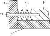
- FIG. 7 is an elevational sectional view of the vicinity of the joint portion of the mesh heat path and the lower support plate support in the fourth embodiment of the core melt holding structure according to the present invention.
- the reticulated heat path 9 and the lower support plate support 7 are connected by fastening bolts 11 to which a disc spring 13 is attached, instead of the heat insulating spacer 10 (see FIG. 3) in the first embodiment.
- the disc spring 13 portion has a considerably smaller cross-sectional area than a heat path structure such as the mesh heat path 9, so that the thermal conductivity is also reduced.
- the thermal conductivity at the joint between the mesh heat path 9 and the lower support plate support 7 is smaller than that of the heat path structure such as the mesh heat path 9. For this reason, the heat of the core melt 3 is not easily transmitted to the lower support plate support 7, and the possibility that the lower support plate support 7 is melted is small. If the lower support plate support 7 is not melted, the reticulated heat path 9 and the height direction heat path 8 are supported by the lower support plate support part and fall into the core melt 3 even under the condition that the entire lower support plate 6 is melted. do not do.
- the mesh heat path 9 is in direct contact with the lower support plate support 7 to support the lower support plate.
- the possibility of melting 7 can be reduced.
- the disc spring 13 at the connection portion the thermal expansion of the mesh heat path 9 can be absorbed.
- FIG. 8 is an elevational sectional view of the vicinity of the joint portion between the mesh heat path and the lower support plate support in the fifth embodiment of the core melt holding structure according to the present invention.
- a spacer 14 is used instead of the heat insulating spacer 10 (see FIG. 3) in the first embodiment.
- the spacer 14 of the present embodiment is a hollow cylinder.
- the reticulated heat path 9 and the lower support plate support 7 are coupled by fastening bolts 11 that pass through the hollow portion of the spacer 14. Since the spacer 14 is a hollow cylinder, its cross-sectional area is considerably smaller than that of the mesh heat path 9, so that the thermal resistance is increased.
- the thermal conductivity at the joint between the mesh heat path 9 and the lower support plate support 7 is smaller than that of the heat path structure such as the mesh heat path 9. Further, a contact thermal resistance is generated at a contact portion between the reticulated heat path 9 and the spacer 14 and a contact portion between the spacer 14 and the lower support plate support 7. For this reason, the heat of the core melt 3 is not easily transmitted to the lower support plate support 7, and the possibility that the lower support plate support 7 is melted is small. If the lower support plate support 7 is not melted, the reticulated heat path 9 and the height direction heat path 8 are supported by the lower support plate support part and fall into the core melt 3 even under the condition that the entire lower support plate 6 is melted. do not do.
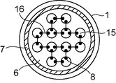
- FIG. 9 is a plan sectional view of a reactor vessel in the sixth embodiment of the core melt holding structure according to the present invention.
- the height direction heat path 8 is fixed to the outer edge of the channel hole 15 formed in the lower support plate 6 and extends downward through the channel hole 15.
- the height direction heat path 8 is provided corresponding to each of the plurality of flow path holes 15.
- the upper ends of the adjacent height direction heat paths 8 are connected by a horizontal heat path 16.
- the height direction heat path 8 attached to the flow path hole 15 is connected to the horizontal direction heat path 16, when holding the core melt 3 (see FIG. 1) in the lower part of the reactor vessel 1, The heat transferred from the directional heat path 16 melts between the flow path holes of the lower support plate 6. For this reason, the flow path holes 15 are connected to each other, and most of the lower support plate 6 can be dropped to the lower part of the reactor vessel 1 and melted.
- the lower support plate is provided under the condition that the amount of core to be melted is small and the core melt 3 supported at the lower part of the reactor vessel 1 does not contact the lower support plate 6. 6 is melted and dropped into the core melt 3.
- the thickness of the metal layer of the core melt 3 deposited in the lower part of the reactor vessel 1 is increased, the concentration of heat generated in the melt core is suppressed, and the possibility of damage to the reactor vessel 1 is reduced. be able to.
- the height direction heat path 8 and the horizontal direction heat path 16 are not supported by the lower support plate 6 due to melting and dropping between the flow path holes 15 of the lower support plate 6. As a result, the height direction heat path 8 and the horizontal direction heat path 16 fall to the lower part of the reactor vessel. Therefore, it is preferable to cover the lower end of the height direction heat path 8 and the connecting portion between the height direction heat path 8 and the horizontal direction heat path 16 with a heat insulating material.
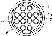
- FIG. 10 is a plan sectional view of a nuclear reactor vessel in the seventh embodiment of the core melt holding structure according to the present invention.
- FIG. 11 is an elevational sectional view of the nuclear reactor vessel in the present embodiment.
- a dam 17 is provided that stands from the upper surface of the lower support plate 6 and surrounds the flow path hole 15 formed in the lower support plate.
- the weir 17 is provided along the edge of the flow path hole 15.
- the weir 17 is made of a high melting point material.
- the core melts and falls to the lower part of the reactor vessel 1 it temporarily accumulates on the lower support plate 6.
- the refractory material weir 17 prevents the core melt from dropping through the flow path hole 15 to the lower part of the reactor vessel 1.
- melting of the lower support plate 6 is promoted by heat transferred from the core melt 3 deposited on the lower support plate 6.
- the thickness of the metal layer of the core melt 3 deposited in the lower part of the reactor vessel 1 is increased, and the concentration of heat generated in the melt core is suppressed, so that The possibility of breakage of the furnace vessel 1 can be reduced.
- SYMBOLS 1 ... Reactor vessel, 2 ... Cooling water, 3 ... Core melt, 6 ... Lower support plate, 7 ... Lower support plate support, 8 ... Height direction heat path, 9 ... Reticulated heat path, 10 ... Thermal insulation spacer, 11 ... Fastening bolt, 12 ... Lower head internal structure, 13 ... Belleville spring, 14 ... Spacer, 15 ... Channel hole, 16 ... Horizontal heat path, 17 ... Weir, 20 ... Insulating material
Landscapes
- Physics & Mathematics (AREA)
- Engineering & Computer Science (AREA)
- Plasma & Fusion (AREA)
- General Engineering & Computer Science (AREA)
- High Energy & Nuclear Physics (AREA)
- Structure Of Emergency Protection For Nuclear Reactors (AREA)
Abstract
Description
図1は、本発明に係る炉心溶融物保持構造体の第1の実施の形態における原子炉の立断面を示す図2のI-I矢視立断面図である。図2は、図1のII-II矢視平断面図である。
図5は、本発明に係る炉心溶融物保持構造体の第2の実施の形態を用いた原子炉の立断面図である。
図6は、本発明に係る炉心溶融物保持構造体の第3の実施の形態を用いた原子炉の立断面図である。
図7は、本発明に係る炉心溶融物保持構造体の第4の実施の形態における網状ヒートパスと下部サポートプレート支持体の結合部分近傍の立断面図である。
図8は、本発明に係る炉心溶融物保持構造体の第5の実施の形態における網状ヒートパスと下部サポートプレート支持体の結合部分近傍の立断面図である。
図9は、本発明に係る炉心溶融物保持構造体の第6の実施の形態における原子炉容器の平断面図である。
図10は、本発明に係る炉心溶融物保持構造体の第7の実施の形態における原子炉容器の平断面図である。図11は、本実施の形態における原子炉容器の立断面図である。
上述の各実施の形態は単なる例示であり、本発明はこれらに限定されない。また、各実施の形態の特徴を組み合わせて実施してもよい。
Claims (9)
- 炉心を収める原子炉容器と、
前記炉心の下方に設けられて前記炉心を支持して上下に貫通する流路孔が形成された下部サポートプレートと、
前記原子炉容器に固定されて前記下部サポートプレートを支持する下部サポートプレート支持体と、
断熱スペーサと、
前記断熱スペーサを介して前記下部サポートプレート支持体に固定されて前記下部サポートプレートに接するサポートプレート接触部とこのサポートプレート接触部から下方に延びる高さ方向伝達部とを備えて前記断熱スペーサよりも熱伝導率が高いヒートパス構造体と、
を有することを特徴とする炉心溶融物保持構造体。 - 前記サポートプレート接触部は前記下部サポートプレートに沿って広がる網目状に形成されていることを特徴とする請求項1に記載の炉心溶融物保持構造体。
- 前記サポートプレート接触部は前記下部サポートプレートに沿って広がる薄板であることを特徴とする請求項1に記載の炉心溶融物保持構造体。
- 前記原子炉容器の下端部に配置された下部ヘッド内構造物をさらに有し、
前記高さ方向伝達部は前記下部ヘッド内構造物に固定されていることを特徴とする請求項1ないし請求項3のいずれか1項に記載の炉心溶融物保持構造体。 - 前記高さ方向伝達部の下端は前記高さ方向伝達部よりも熱伝導率が小さい断熱材で覆われていることを特徴とする請求項1ないし請求項3のいずれか1項に記載の炉心溶融物保持構造体。
- 前記断熱スペーサは前記サポートプレート接触部と前記下部サポートプレート支持部とを接続する皿バネを取り付けた締結ボルトであることを特徴とする請求項1ないし請求項3のいずれか1項に記載の炉心溶融物保持構造体。
- 前記断熱スペーサは前記サポートプレート接触部と下部サポートプレート支持部とを接続するスペーサを取り付けた締結ボルトであることを特徴とする請求項1ないし請求項3のいずれか1項に記載の炉心溶融物保持構造体。
- 炉心を収める原子炉容器と、
前記炉心の下方に設けられて前記炉心を支持して上下に貫通する流路孔が形成された下部サポートプレートと、
前記原子炉容器に固定されて前記下部サポートプレートを支持する下部サポートプレート支持体と、
前記流路孔から下方に延びる複数の高さ方向伝達部と前記下部サポートプレートの上面に接して複数の前記高さ方向伝達部の間を連結する水平方向伝達部とを備えるヒートパス構造体と、
を有することを特徴とする炉心溶融物保持構造体。 - 炉心を収める原子炉容器と、
前記炉心の下方に設けられて前記炉心を支持して上下に貫通する流路孔が形成された下部サポートプレートと、
前記サポートプレートの上面から起立して前記流路孔を囲む堰と、
前記原子炉容器に固定されて前記下部サポートプレートを支持する下部サポートプレート支持体と、
を有することを特徴とする炉心溶融物保持構造体。
Priority Applications (4)
| Application Number | Priority Date | Filing Date | Title |
|---|---|---|---|
| KR1020127026978A KR101439721B1 (ko) | 2010-04-23 | 2011-04-06 | 노심 용융물 유지 구조체 |
| CN201180019662.8A CN102870164B (zh) | 2010-04-23 | 2011-04-06 | 堆芯熔融物保持构造体 |
| GB1217308.4A GB2491770B (en) | 2010-04-23 | 2011-04-06 | Molten-core retention structure |
| US13/647,887 US20130272472A1 (en) | 2010-04-23 | 2012-10-09 | Molten-core retention structure |
Applications Claiming Priority (2)
| Application Number | Priority Date | Filing Date | Title |
|---|---|---|---|
| JP2010-100119 | 2010-04-23 | ||
| JP2010100119A JP5582858B2 (ja) | 2010-04-23 | 2010-04-23 | 炉心溶融物保持構造体 |
Related Child Applications (1)
| Application Number | Title | Priority Date | Filing Date |
|---|---|---|---|
| US13/647,887 Continuation-In-Part US20130272472A1 (en) | 2010-04-23 | 2012-10-09 | Molten-core retention structure |
Publications (1)
| Publication Number | Publication Date |
|---|---|
| WO2011132370A1 true WO2011132370A1 (ja) | 2011-10-27 |
Family
ID=44833915
Family Applications (1)
| Application Number | Title | Priority Date | Filing Date |
|---|---|---|---|
| PCT/JP2011/002032 Ceased WO2011132370A1 (ja) | 2010-04-23 | 2011-04-06 | 炉心溶融物保持構造体 |
Country Status (6)
| Country | Link |
|---|---|
| US (1) | US20130272472A1 (ja) |
| JP (1) | JP5582858B2 (ja) |
| KR (1) | KR101439721B1 (ja) |
| CN (1) | CN102870164B (ja) |
| GB (1) | GB2491770B (ja) |
| WO (1) | WO2011132370A1 (ja) |
Families Citing this family (6)
| Publication number | Priority date | Publication date | Assignee | Title |
|---|---|---|---|---|
| JP5710240B2 (ja) * | 2010-12-27 | 2015-04-30 | 株式会社東芝 | 炉心溶融物の保持装置 |
| JP5859902B2 (ja) * | 2012-04-13 | 2016-02-16 | 日立Geニュークリア・エナジー株式会社 | 原子炉設備 |
| CN103177778A (zh) * | 2013-01-08 | 2013-06-26 | 上海核工程研究设计院 | 底部注水叠加外部冷却的大型非能动核电厂堆芯捕集器 |
| CN105551540B (zh) * | 2015-12-16 | 2019-12-13 | 中国核电工程有限公司 | 一种堆芯熔融物分组捕集容器 |
| KR102649036B1 (ko) * | 2022-03-14 | 2024-03-18 | 한국수력원자력 주식회사 | 소형원자로 냉각장치 및 냉각방법 |
| CN116386910B (zh) * | 2022-11-28 | 2024-02-13 | 上海核工程研究设计院股份有限公司 | 一种提高堆芯熔融物滞留有效性的反应堆压力容器及方法 |
Citations (6)
| Publication number | Priority date | Publication date | Assignee | Title |
|---|---|---|---|---|
| JPS50125196A (ja) * | 1974-03-20 | 1975-10-01 | ||
| JPS5162296A (en) * | 1974-11-29 | 1976-05-29 | Tokyo Shibaura Electric Co | Genshirono yojunenryohojisochi |
| JPS5298889A (en) * | 1976-02-11 | 1977-08-19 | Westinghouse Electric Corp | Core molten matter collecting device |
| JP2000504119A (ja) * | 1996-09-25 | 2000-04-04 | イル スン ファン | 原子炉容器用間隙構造物 |
| JP2000121771A (ja) * | 1998-10-14 | 2000-04-28 | Commiss Energ Atom | 可変形内部構造を収容しているレセプタクルを備えた水利用型原子炉 |
| JP2003240887A (ja) * | 2002-02-15 | 2003-08-27 | Toshiba Corp | 原子炉圧力容器 |
Family Cites Families (6)
| Publication number | Priority date | Publication date | Assignee | Title |
|---|---|---|---|---|
| US4252612A (en) * | 1977-10-10 | 1981-02-24 | United Kingdom Atomic Energy Authority | Nuclear reactors |
| US4756877A (en) * | 1985-11-06 | 1988-07-12 | Westinghouse Electric Corp. | Core barrel support system for nuclear reactors |
| DE4319093A1 (de) * | 1993-06-08 | 1994-12-15 | Siemens Ag | Einrichtung zum Auffangen von Kernschmelze aus einem Reaktordruckbehälter |
| DE69621656D1 (de) * | 1996-09-25 | 2002-07-11 | Il Soon Hwang | Abstandshalter-und kühlungs-struktur für einen kernreaktor |
| JP3035276B1 (ja) * | 1998-10-15 | 2000-04-24 | 三菱重工業株式会社 | 原子炉容器の炉心支持構造物 |
| JP4077091B2 (ja) * | 1998-11-24 | 2008-04-16 | 株式会社東芝 | 沸騰水型原子炉 |
-
2010
- 2010-04-23 JP JP2010100119A patent/JP5582858B2/ja not_active Expired - Fee Related
-
2011
- 2011-04-06 KR KR1020127026978A patent/KR101439721B1/ko not_active Expired - Fee Related
- 2011-04-06 WO PCT/JP2011/002032 patent/WO2011132370A1/ja not_active Ceased
- 2011-04-06 CN CN201180019662.8A patent/CN102870164B/zh not_active Expired - Fee Related
- 2011-04-06 GB GB1217308.4A patent/GB2491770B/en not_active Expired - Fee Related
-
2012
- 2012-10-09 US US13/647,887 patent/US20130272472A1/en not_active Abandoned
Patent Citations (6)
| Publication number | Priority date | Publication date | Assignee | Title |
|---|---|---|---|---|
| JPS50125196A (ja) * | 1974-03-20 | 1975-10-01 | ||
| JPS5162296A (en) * | 1974-11-29 | 1976-05-29 | Tokyo Shibaura Electric Co | Genshirono yojunenryohojisochi |
| JPS5298889A (en) * | 1976-02-11 | 1977-08-19 | Westinghouse Electric Corp | Core molten matter collecting device |
| JP2000504119A (ja) * | 1996-09-25 | 2000-04-04 | イル スン ファン | 原子炉容器用間隙構造物 |
| JP2000121771A (ja) * | 1998-10-14 | 2000-04-28 | Commiss Energ Atom | 可変形内部構造を収容しているレセプタクルを備えた水利用型原子炉 |
| JP2003240887A (ja) * | 2002-02-15 | 2003-08-27 | Toshiba Corp | 原子炉圧力容器 |
Also Published As
| Publication number | Publication date |
|---|---|
| JP2011232048A (ja) | 2011-11-17 |
| US20130272472A1 (en) | 2013-10-17 |
| CN102870164B (zh) | 2015-12-16 |
| CN102870164A (zh) | 2013-01-09 |
| KR101439721B1 (ko) | 2014-09-12 |
| GB2491770B (en) | 2016-04-06 |
| GB2491770A (en) | 2012-12-12 |
| JP5582858B2 (ja) | 2014-09-03 |
| KR20120132551A (ko) | 2012-12-05 |
| GB201217308D0 (en) | 2012-11-14 |
Similar Documents
| Publication | Publication Date | Title |
|---|---|---|
| JP5582858B2 (ja) | 炉心溶融物保持構造体 | |
| CN107210070B (zh) | 水冷、水慢化反应堆堆芯熔融物的冷却和封闭系统 | |
| CN107251152B (zh) | 核反应堆堆芯熔融物的冷却和封闭系统 | |
| WO2007099698A1 (ja) | コアキャッチャーおよびその製造方法、並びに、原子炉格納容器およびその改造方法 | |
| CN107251153B (zh) | 核反应堆堆芯熔融物的冷却和封闭系统 | |
| CN101390170A (zh) | 堆芯收集器及其制造方法、以及核反应堆外壳及其制造方法 | |
| JP2013104711A (ja) | 液体金属冷却原子炉 | |
| CN106663479A (zh) | 用于冷却堆芯熔体的多孔冷却块及包含所述多孔冷却块的堆芯熔体冷却设备、使用所述多孔冷却块的堆芯熔体冷却方法 | |
| JP2011169764A (ja) | 炉心溶融物冷却装置および原子炉格納容器 | |
| JPH06130169A (ja) | 原子炉設備 | |
| US9384863B2 (en) | Apparatus for retention of molten material outside generation IV reactor after nuclear power plant accident | |
| JP5377064B2 (ja) | 炉心溶融物保持装置および原子力プラント | |
| JP3263402B2 (ja) | 原子炉容器用間隙構造物 | |
| JP2009052951A (ja) | 炉心溶融物冷却装置および原子炉格納容器 | |
| JP2008241657A (ja) | 原子炉格納容器 | |
| JP2010271261A (ja) | 炉心溶融物保持装置および格納容器 | |
| JP4828963B2 (ja) | 炉心溶融物冷却装置、原子炉格納容器および炉心溶融物冷却装置の設置方法 | |
| JPH09211166A (ja) | 原子炉のコアキャッチャー | |
| JP2010038571A (ja) | 炉心溶融物冷却装置および炉心溶融物冷却方法 | |
| JP2017187370A (ja) | 原子炉格納容器および溶融炉心受装置 | |
| JP6204823B2 (ja) | コアキャッチャ | |
| JP2012021877A (ja) | 炉心溶融物保持装置および格納容器 | |
| JP2008139023A (ja) | 原子炉溶融物保持装置および原子炉格納容器 | |
| JP2011232089A (ja) | 原子炉 | |
| WO2013150750A1 (ja) | 原子炉圧力容器の貫通部保護構造及び原子炉 |
Legal Events
| Date | Code | Title | Description |
|---|---|---|---|
| WWE | Wipo information: entry into national phase |
Ref document number: 201180019662.8 Country of ref document: CN |
|
| 121 | Ep: the epo has been informed by wipo that ep was designated in this application |
Ref document number: 11771714 Country of ref document: EP Kind code of ref document: A1 |
|
| ENP | Entry into the national phase |
Ref document number: 1217308 Country of ref document: GB Kind code of ref document: A Free format text: PCT FILING DATE = 20110406 |
|
| WWE | Wipo information: entry into national phase |
Ref document number: 1217308.4 Country of ref document: GB |
|
| ENP | Entry into the national phase |
Ref document number: 20127026978 Country of ref document: KR Kind code of ref document: A |
|
| NENP | Non-entry into the national phase |
Ref country code: DE |
|
| 122 | Ep: pct application non-entry in european phase |
Ref document number: 11771714 Country of ref document: EP Kind code of ref document: A1 |