WO2011132219A1 - ドア開閉装置 - Google Patents
ドア開閉装置 Download PDFInfo
- Publication number
- WO2011132219A1 WO2011132219A1 PCT/JP2010/002846 JP2010002846W WO2011132219A1 WO 2011132219 A1 WO2011132219 A1 WO 2011132219A1 JP 2010002846 W JP2010002846 W JP 2010002846W WO 2011132219 A1 WO2011132219 A1 WO 2011132219A1
- Authority
- WO
- WIPO (PCT)
- Prior art keywords
- door
- door opening
- closing device
- guide
- closing
- Prior art date
- Legal status (The legal status is an assumption and is not a legal conclusion. Google has not performed a legal analysis and makes no representation as to the accuracy of the status listed.)
- Ceased
Links
Images



Classifications
-
- E—FIXED CONSTRUCTIONS
- E05—LOCKS; KEYS; WINDOW OR DOOR FITTINGS; SAFES
- E05F—DEVICES FOR MOVING WINGS INTO OPEN OR CLOSED POSITION; CHECKS FOR WINGS; WING FITTINGS NOT OTHERWISE PROVIDED FOR, CONCERNED WITH THE FUNCTIONING OF THE WING
- E05F15/00—Power-operated mechanisms for wings
- E05F15/60—Power-operated mechanisms for wings using electrical actuators
- E05F15/603—Power-operated mechanisms for wings using electrical actuators using rotary electromotors
- E05F15/611—Power-operated mechanisms for wings using electrical actuators using rotary electromotors for swinging wings
- E05F15/627—Power-operated mechanisms for wings using electrical actuators using rotary electromotors for swinging wings operated by flexible elongated pulling elements, e.g. belts, chains or cables
-
- E—FIXED CONSTRUCTIONS
- E05—LOCKS; KEYS; WINDOW OR DOOR FITTINGS; SAFES
- E05F—DEVICES FOR MOVING WINGS INTO OPEN OR CLOSED POSITION; CHECKS FOR WINGS; WING FITTINGS NOT OTHERWISE PROVIDED FOR, CONCERNED WITH THE FUNCTIONING OF THE WING
- E05F15/00—Power-operated mechanisms for wings
- E05F15/60—Power-operated mechanisms for wings using electrical actuators
- E05F15/603—Power-operated mechanisms for wings using electrical actuators using rotary electromotors
- E05F15/632—Power-operated mechanisms for wings using electrical actuators using rotary electromotors for horizontally-sliding wings
- E05F15/643—Power-operated mechanisms for wings using electrical actuators using rotary electromotors for horizontally-sliding wings operated by flexible elongated pulling elements, e.g. belts, chains or cables
-
- E—FIXED CONSTRUCTIONS
- E05—LOCKS; KEYS; WINDOW OR DOOR FITTINGS; SAFES
- E05F—DEVICES FOR MOVING WINGS INTO OPEN OR CLOSED POSITION; CHECKS FOR WINGS; WING FITTINGS NOT OTHERWISE PROVIDED FOR, CONCERNED WITH THE FUNCTIONING OF THE WING
- E05F15/00—Power-operated mechanisms for wings
- E05F15/60—Power-operated mechanisms for wings using electrical actuators
- E05F15/603—Power-operated mechanisms for wings using electrical actuators using rotary electromotors
- E05F15/611—Power-operated mechanisms for wings using electrical actuators using rotary electromotors for swinging wings
- E05F15/616—Power-operated mechanisms for wings using electrical actuators using rotary electromotors for swinging wings operated by push-pull mechanisms
-
- E—FIXED CONSTRUCTIONS
- E05—LOCKS; KEYS; WINDOW OR DOOR FITTINGS; SAFES
- E05Y—INDEXING SCHEME ASSOCIATED WITH SUBCLASSES E05D AND E05F, RELATING TO CONSTRUCTION ELEMENTS, ELECTRIC CONTROL, POWER SUPPLY, POWER SIGNAL OR TRANSMISSION, USER INTERFACES, MOUNTING OR COUPLING, DETAILS, ACCESSORIES, AUXILIARY OPERATIONS NOT OTHERWISE PROVIDED FOR, APPLICATION THEREOF
- E05Y2201/00—Constructional elements; Accessories therefor
- E05Y2201/40—Motors; Magnets; Springs; Weights; Accessories therefor
- E05Y2201/43—Motors
- E05Y2201/434—Electromotors; Details thereof
-
- E—FIXED CONSTRUCTIONS
- E05—LOCKS; KEYS; WINDOW OR DOOR FITTINGS; SAFES
- E05Y—INDEXING SCHEME ASSOCIATED WITH SUBCLASSES E05D AND E05F, RELATING TO CONSTRUCTION ELEMENTS, ELECTRIC CONTROL, POWER SUPPLY, POWER SIGNAL OR TRANSMISSION, USER INTERFACES, MOUNTING OR COUPLING, DETAILS, ACCESSORIES, AUXILIARY OPERATIONS NOT OTHERWISE PROVIDED FOR, APPLICATION THEREOF
- E05Y2201/00—Constructional elements; Accessories therefor
- E05Y2201/60—Suspension or transmission members; Accessories therefor
- E05Y2201/604—Transmission members
-
- E—FIXED CONSTRUCTIONS
- E05—LOCKS; KEYS; WINDOW OR DOOR FITTINGS; SAFES
- E05Y—INDEXING SCHEME ASSOCIATED WITH SUBCLASSES E05D AND E05F, RELATING TO CONSTRUCTION ELEMENTS, ELECTRIC CONTROL, POWER SUPPLY, POWER SIGNAL OR TRANSMISSION, USER INTERFACES, MOUNTING OR COUPLING, DETAILS, ACCESSORIES, AUXILIARY OPERATIONS NOT OTHERWISE PROVIDED FOR, APPLICATION THEREOF
- E05Y2201/00—Constructional elements; Accessories therefor
- E05Y2201/60—Suspension or transmission members; Accessories therefor
- E05Y2201/622—Suspension or transmission members elements
- E05Y2201/644—Flexible elongated pulling elements
- E05Y2201/652—Belts
-
- E—FIXED CONSTRUCTIONS
- E05—LOCKS; KEYS; WINDOW OR DOOR FITTINGS; SAFES
- E05Y—INDEXING SCHEME ASSOCIATED WITH SUBCLASSES E05D AND E05F, RELATING TO CONSTRUCTION ELEMENTS, ELECTRIC CONTROL, POWER SUPPLY, POWER SIGNAL OR TRANSMISSION, USER INTERFACES, MOUNTING OR COUPLING, DETAILS, ACCESSORIES, AUXILIARY OPERATIONS NOT OTHERWISE PROVIDED FOR, APPLICATION THEREOF
- E05Y2201/00—Constructional elements; Accessories therefor
- E05Y2201/60—Suspension or transmission members; Accessories therefor
- E05Y2201/622—Suspension or transmission members elements
- E05Y2201/686—Rods, links
-
- E—FIXED CONSTRUCTIONS
- E05—LOCKS; KEYS; WINDOW OR DOOR FITTINGS; SAFES
- E05Y—INDEXING SCHEME ASSOCIATED WITH SUBCLASSES E05D AND E05F, RELATING TO CONSTRUCTION ELEMENTS, ELECTRIC CONTROL, POWER SUPPLY, POWER SIGNAL OR TRANSMISSION, USER INTERFACES, MOUNTING OR COUPLING, DETAILS, ACCESSORIES, AUXILIARY OPERATIONS NOT OTHERWISE PROVIDED FOR, APPLICATION THEREOF
- E05Y2400/00—Electronic control; Electrical power; Power supply; Power or signal transmission; User interfaces
- E05Y2400/10—Electronic control
- E05Y2400/32—Position control, detection or monitoring
- E05Y2400/334—Position control, detection or monitoring by using pulse generators
- E05Y2400/336—Position control, detection or monitoring by using pulse generators of the angular type
-
- E—FIXED CONSTRUCTIONS
- E05—LOCKS; KEYS; WINDOW OR DOOR FITTINGS; SAFES
- E05Y—INDEXING SCHEME ASSOCIATED WITH SUBCLASSES E05D AND E05F, RELATING TO CONSTRUCTION ELEMENTS, ELECTRIC CONTROL, POWER SUPPLY, POWER SIGNAL OR TRANSMISSION, USER INTERFACES, MOUNTING OR COUPLING, DETAILS, ACCESSORIES, AUXILIARY OPERATIONS NOT OTHERWISE PROVIDED FOR, APPLICATION THEREOF
- E05Y2600/00—Mounting or coupling arrangements for elements provided for in this subclass
- E05Y2600/10—Adjustable
- E05Y2600/30—Adjustment motion
- E05Y2600/32—Rotary motion
- E05Y2600/324—Rotary motion around a vertical axis
-
- E—FIXED CONSTRUCTIONS
- E05—LOCKS; KEYS; WINDOW OR DOOR FITTINGS; SAFES
- E05Y—INDEXING SCHEME ASSOCIATED WITH SUBCLASSES E05D AND E05F, RELATING TO CONSTRUCTION ELEMENTS, ELECTRIC CONTROL, POWER SUPPLY, POWER SIGNAL OR TRANSMISSION, USER INTERFACES, MOUNTING OR COUPLING, DETAILS, ACCESSORIES, AUXILIARY OPERATIONS NOT OTHERWISE PROVIDED FOR, APPLICATION THEREOF
- E05Y2600/00—Mounting or coupling arrangements for elements provided for in this subclass
- E05Y2600/50—Mounting methods; Positioning
- E05Y2600/502—Clamping
-
- E—FIXED CONSTRUCTIONS
- E05—LOCKS; KEYS; WINDOW OR DOOR FITTINGS; SAFES
- E05Y—INDEXING SCHEME ASSOCIATED WITH SUBCLASSES E05D AND E05F, RELATING TO CONSTRUCTION ELEMENTS, ELECTRIC CONTROL, POWER SUPPLY, POWER SIGNAL OR TRANSMISSION, USER INTERFACES, MOUNTING OR COUPLING, DETAILS, ACCESSORIES, AUXILIARY OPERATIONS NOT OTHERWISE PROVIDED FOR, APPLICATION THEREOF
- E05Y2800/00—Details, accessories and auxiliary operations not otherwise provided for
- E05Y2800/20—Combinations of elements
- E05Y2800/23—Combinations of elements of elements of different categories
- E05Y2800/232—Combinations of elements of elements of different categories of motors and transmissions
-
- E—FIXED CONSTRUCTIONS
- E05—LOCKS; KEYS; WINDOW OR DOOR FITTINGS; SAFES
- E05Y—INDEXING SCHEME ASSOCIATED WITH SUBCLASSES E05D AND E05F, RELATING TO CONSTRUCTION ELEMENTS, ELECTRIC CONTROL, POWER SUPPLY, POWER SIGNAL OR TRANSMISSION, USER INTERFACES, MOUNTING OR COUPLING, DETAILS, ACCESSORIES, AUXILIARY OPERATIONS NOT OTHERWISE PROVIDED FOR, APPLICATION THEREOF
- E05Y2900/00—Application of doors, windows, wings or fittings thereof
- E05Y2900/10—Application of doors, windows, wings or fittings thereof for buildings or parts thereof
- E05Y2900/13—Type of wing
- E05Y2900/132—Doors
Definitions
- the present invention relates to a door opening / closing device.
- Patent Document 1 a door opening and closing device that opens and closes a door by using a rotational output of a motor as a door opening and closing driving force is known.
- a reduction gear for reducing the rotational speed of the motor is provided, and the reduction gear has a plurality of gears and performs a reduction between the gears. It has become.
- the gear of the final stage and the drive shaft of the door are engaged with each other, whereby the rotation shaft of the motor is decelerated at a high reduction ratio by the speed reducer and transmitted to the drive shaft of the door.
- the rotation shaft of the motor is decelerated by a speed reducer having a plurality of gears. Therefore, the door opening and closing apparatus is made compact and lightweight by the amount of the speed reducer. It has become difficult.
- the speed reducer is not provided, it is necessary to control the opening and closing of the door in the range of the rotation angle of the motor less than 90 degrees, and there are too few pulses that the motor outputs according to the rotation. It is impossible to control the rotation of the door.
- a high-resolution encoder can be provided, it is expensive and the door opening / closing device cannot be made compact.
- An object of the present invention is to provide a door opening / closing device with high cost performance capable of performing door opening / closing control without using a reduction gear with a high reduction ratio or a high resolution encoder.
- a door opening and closing device is a door opening and closing device for opening and closing a door, the brushless motor having a magnet position detection element, and the brushless according to a signal output from the magnet position detection element
- a controller that performs drive control of the motor, a drive wheel portion that receives the rotational driving force of the brushless motor, a driven wheel portion that is rotatable about an axis parallel to a rotation axis of the drive wheel portion, the drive wheel portion, and the A linear motion mechanism having a winding member wound around the driven wheel portion, and a coupling mechanism coupled to the winding member and interlocking the movement of the door with the winding member.
- the moving mechanism is a door opening and closing device in which the driving wheel portion is set to rotate a plurality of times while the connecting mechanism moves in one direction in conjunction with the winding member.
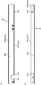
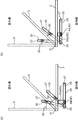
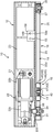
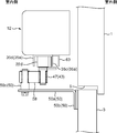
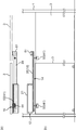
- FIG. 1 It is the schematic of the door opening / closing apparatus of the state which actually attached the door opening / closing apparatus shown in FIG. (A) It is the schematic when the door opening / closing apparatus which concerns on 3rd Embodiment of this invention is seen from the top, (b) The outline when the door opening / closing apparatus which concerns on 3rd Embodiment of this invention is seen from the front. FIG.
- the door opening and closing device 10 As shown in FIGS. 1 to 3, the door opening and closing device 10 according to the first embodiment is attached to the indoor side surface of the wall 1 of the building, and opens the door (a hinged door) 3 toward the outdoor side. It is an opening and closing device for doing.
- the door opening and closing device 10 includes a door engine unit 12 fixed to a wall surface on the indoor side of a wall 1 of a building, a linear motion mechanism 14 disposed below the door engine unit 12, and a linear motion mechanism. 14 includes a connecting mechanism 16 for transmitting the movement of the door 14 to the door 3 and a guide component 18 for defining the moving direction of the connecting mechanism 16.
- the door engine unit 12 is disposed on the indoor side with respect to the wall body 1, and the linear motion mechanism 14, the coupling mechanism 16, and the guide component 18 are disposed on the indoor side with respect to the door 3. ing.
- the door engine unit 12 includes a case 21 arranged in a posture extending in the opening width direction along the upper edge of the opening 5 of the wall 1.
- the case 21 mainly houses a brushless motor 22 and a door controller 23.
- the brushless motor 22 has a hall element 22a which is a magnet position detection element, and outputs a signal corresponding to a signal output from the hall element 22a. That is, in the brushless motor 22, for example, a magnet is fixed to a rotor (not shown), and a large number of hall elements 22a are arranged in the circumferential direction on a stator (not shown). The signal output from the Hall element 22a changes according to the rotation angle of the rotor.
- the brushless motor 22 is a direct current (DC) brushless motor, but an alternating current (AC) brushless motor can also be used.
- the signal output from the brushless motor 22 is received by the door controller 23, and the door controller 23 controls the driving of the brushless motor 22 in accordance with the received signal.
- a geared motor is used as the brushless motor 22. That is, the brushless motor 22 is provided with a motor main body 22b and a speed reduction mechanism 22c, and the output shaft 22d of the brushless motor 22 is rotated at a rotational speed obtained by reducing the rotational speed of the motor main body 22b by the speed reduction mechanism 22c.
- the brushless motor 22 is fixed to the case 21 with the output shaft 22d facing downward.
- the linear motion mechanism 14 includes a driving pulley 26 that is a driving wheel portion, an idler pulley 27 that is a driven wheel portion, and a belt (winding member) 28 that is wound around the driving pulley 26 and the idler pulley 27.
- the drive pulley 26 is formed with a through hole, and is externally fitted to the output shaft 22d of the brushless motor 22 at a position below the case 21, and is fixed to the output shaft 22d.
- the idler pulley 27 is rotatably attached to a rail member 35 described later via a bearing bracket 30.
- the rotation axis of the idler pulley 27 is parallel to the rotation axis of the drive pulley 26. That is, the drive pulley 26 and the idler pulley 27 have a posture in which the rotation axis extends in the vertical direction.
- a support bracket 32 for supporting the shaft member 29 of the drive pulley 26 is disposed below the case 21.
- the support bracket 32 includes a contact portion 32a that contacts the lower surface of the case 21 in the vicinity of the output shaft 22d, and a support portion 32b that is disposed horizontally (parallel to the contact portion 32a) below the contact portion 32a. .
- the contact portion 32 a is disposed outside the case 21.
- the shaft member 29 is provided coaxially with the output shaft 22d and fixed to the support portion 32b.
- the shaft member 29 is fixed to the support portion 32b at the lower small diameter portion.
- a large-diameter cylindrical portion of the spacer member 31 is disposed on the radially outer side of the large-diameter portion of the shaft member 29.
- the spacer member 31 is coupled to a rail member 35 described later. For this reason, the spacer member 31 is rotatable with respect to the support portion 32 b as the rail member 35 rotates.
- a thin cylindrical bush 33 is disposed between the shaft member 29 and the large-diameter cylindrical portion of the spacer member 31, and the spacer member 31 rotates with respect to the shaft member 29 via the bush 33. It is possible to move.
- a bearing 34 is provided between the drive pulley 26 and the stepped portion of the shaft member 29, and the drive pulley 26 is rotatable with respect to the shaft member 29.
- the connecting mechanism 16 includes a connecting portion 40 that moves integrally with the belt 28, and a door coupling member 41 that can rotate with respect to the connecting portion 40.
- the connecting unit 40 includes a fixing unit 43 attached to the belt 28 and a rolling element 44 configured to be rotatable with respect to the fixing unit 43.
- the fixing unit 43 includes a mounting member 45 made of a sheet metal (see FIGS. 4A and 4B) and a clamp fitting 46 fixed to the mounting member 45 and fixed to the belt 28 (FIGS. 5A and 5B). And a pin-shaped shaft portion 47 that is fixed to the mounting member 45 and extends in the vertical direction.
- the attachment member 45 is formed by bending a flat sheet metal, and has a bottom 45a that is long in one direction and side portions 45b that rise from both ends of the bottom 45a. And integrally.
- a through hole 45c through which the shaft portion 47 can be inserted is formed at the center of the bottom portion 45a. Further, a long hole 45d for adjusting the position of the clamp fitting 46 is formed in the bottom 45a.
- each clamp fitting 46 is fastened with a fastener (bolt) inserted through the long hole 45 d of the mounting member 45.
- Fastening holes 46a are provided for this purpose.
- Each clamp fitting 46 is disposed on both sides of the rolling element 44 and fastened to the mounting member 45.
- One clamp fitting 46 is fixed to one end of the belt 28, and the other clamp fitting 46 is fixed to the other end of the belt 28. That is, as will be described later, in the belt 28, one wall portion 35d of the two wall portions 35c and 35d of the guide portion 35a is located outside the belt 28, and the rolling elements 44 are arranged along the wall portion 35d. In order to roll, the belt 28 is not an endless member, but a belt that is interrupted in the middle is used.
- the clamp fittings 46 are attached to both ends of the belt 28, and both the clamp fittings 46 are fixed to the attachment member 45.
- the belt 28 and the attachment member 45 are coupled to each other to form an endless member, and the endless member is stretched over the drive pulley 26 and the idler pulley 27.
- both end portions of the belt 28 are located in a straight portion of the endless member on the indoor side (the side farther from the door 3), and the attachment member 45 is closer to the door than the shafts of the pulleys 26 and 27. Reciprocates linearly away from 3.
- the shaft portion 47 is fixed to the mounting member 45 by bolts.
- a rolling element 44 is rotatably fitted on a portion of the shaft portion 47 located on the inner side (upper side) of the attachment member 45.
- a door coupling member 41 is rotatably coupled to a portion of the shaft portion 47 located outside (lower side) of the attachment member 45.
- the door coupling member 41 is a member coupled to the door 3, and includes a cylindrical member 49 that is externally fitted to the shaft portion 47 of the fixing unit 43, and a suspension member 50 that is fixed to the cylindrical member 49. . Since the door coupling member 41 is rotatable about the vertical axis with respect to the shaft portion 47 (connecting portion 40) of the fixing portion 43, the direction of the door 3 changes with respect to the moving direction of the connecting portion 40. Will not interfere.
- the suspension member 50 integrally includes a horizontal portion 50 a fixed to the cylindrical member 49 and a hanging portion 50 b extending downward from an end portion of the horizontal portion 50 a.
- the hanging portion 50 b is attached to the door 3. Can be concluded. Since the suspension member 50 includes the horizontal portion 50a projecting in the horizontal direction, the door opening and closing device 10 can be disposed in a state where the linear movement direction of the connecting portion 40 is deviated from the rotation center of the door 3. In addition, what is necessary is just to select the thing of the length according to the thickness of the wall 1 of a building suitably for the horizontal part 50a of the suspension member 50 (refer Fig.7 (a) (b)).
- the guide component 18 is for guiding the connecting portion 40 of the linear motion mechanism 14, and is disposed below the door engine portion 12 as with the linear motion mechanism 14.
- the guide component 18 includes a rail member 35 in which a guide portion 35a and a main body portion 35b are integrally provided.
- the rail member 35 has a shape that is long in one direction, and is coupled to the bearing member 31 of the drive pulley 26 at one end thereof. For this reason, the rail member 35 is rotatable about the output shaft 22d and the drive pulley 26 about the same axis.
- the spacer member 31 is welded to a coupling member 52 that is fastened to the main body portion 35b of the rail member 35.
- an idler pulley 27 is attached to the main body portion 35b, the main body portion 35b of the rail member 35 is horizontal, and the guide portion 35a extends downward from both sides in the width direction of the main body portion 35b. It is arranged in a protruding form. And the guide part 35a is provided with two wall parts 35c and 35d arrange
- the rail member 35 has a configuration in which both end portions of one wall portion 35c are cut out in a rectangular shape.
- the notch 35e has a bearing member 31 of the drive pulley 26 and a bearing bracket of the idler pulley 27 in a state in which a part of the drive pulley 26 and the idler pulley 27 protrudes outside the guide portion 35a. 30 is provided to enable disposition.
- the bearing bracket 30 of the idler pulley 27 is fastened to the other wall portion 35d by a bolt.
- the belt 28 is wound around the drive pulley 26 and the idler pulley 27.
- One of the linear portions of the belt 28 is located between the two wall portions 35c and 35d, and the other is outside the wall portion 35c. Is located.
- the rolling element 44 of the connection part 40 is located between the two wall parts 35c and 35d, and can roll along the inner surface of both wall parts 35c and 35d.
- the rotation center of the rolling element 44 that is, the center of the connecting portion 40 is offset to the side of the line connecting the rotation axis of the drive pulley 26 and the rotation axis of the idler pulley 27 with respect to the belt 28.
- an insertion portion 35f for inserting the output shaft 22d is cut out in the main body portion 35b of the rail member 35.
- FIG.7 (b) the opening / closing operation
- the door 3 in the closed position which closed the opening part 5 of the wall 1 is shown as the continuous line, and the door 3 in the open position where the opening part 5 was open
- the suspension member 50 is shown by one straight line for convenience.
- the rotation center of the door 3 is shown as O.
- This rotation center O represents a hinge position (hinge) that allows the door 3 to swing open and close with respect to the wall 1, and is located on the outdoor side of the axial end of the door 3 in the closed position. Set to position.
- the connecting portion 40 When the door 3 is in a position (closed position) where the opening 5 is closed, the connecting portion 40 is positioned relatively close to the drive pulley 26. In order to open the door 3, the brushless motor 22 is driven and the drive pulley 26 rotates. Thereby, the belt 28 and the connection part 40 move toward the idler pulley 27 (door end side). At this time, since the rolling element 44 of the connecting portion 40 rolls along the pair of wall portions 35c and 35d of the rail member 35, the connecting portion 40 moves straight.
- the force that moves the coupling portion 40 toward the door end side is It acts on the door 3 as a moment for rotating the door 3 to which the door coupling member 41 is coupled around the rotation center O. Therefore, with the movement of the connecting portion 40, the door 3 opens toward the outdoor side, and the opening 5 of the wall 1 is opened. At this time, the output shaft 22d of the brushless motor 22 rotates a plurality of times while the door 3 is fully opened. Therefore, the position can be accurately controlled by the door controller 23. When the door 3 is moved from the open position to the closed position, the output shaft 22d of the brushless motor 22 may be rotated in the opposite direction.
- the door 3 is closed while the connecting mechanism 16 that connects the belt 28 and the door 3 moves in one direction as the driving pulley 26 rotates. From the fully open position to the closed position.
- the controller 23 performs drive control of the brushless motor 22 based on a signal output from the hall element 22a. Therefore, opening / closing control of the door 3 can be performed without using a high-resolution encoder. For this reason, the whole apparatus can be made compact.
- the drive pulley 26 of the linear motion mechanism 14 rotates a plurality of times while the coupling mechanism 16 moves in one direction, and therefore, between the brushless motor 22 and the drive pulley 26.
- the opening / closing control or stop position control of the door 3 can be performed without using a reduction gear having a high reduction ratio. Further, since the rotational speed of the motor 22 is decelerated by the linear motion mechanism 14, a clutch required when using a gear reducer with a high reduction ratio using gears is basically unnecessary.
- the door opening / closing device 10 is quiet.
- the connecting portion 40 moves while being guided by the guide portion 35a. Therefore, the movement direction of the door 3 can be stabilized by the rotation of the drive pulley 26.
- the connecting portion 40 moves while being guided by the guide portion 35a of the rail member 35. At this time, the connecting portion 40 moves together with the belt 28 while the door connecting member 41 rotates with respect to the connecting portion 40. Thereby, the door 3 can be swing-opened.
- the guide component 18 having the guide portion 35 a for guiding the coupling mechanism 16 is configured to be rotatable with respect to the door engine portion 12.
- the door 3 can be opened / closed by swinging even when fixed to the door.
- the vertical width (height) of the linear motion mechanism 14 and the guide component 18 is further reduced. be able to.
- the rolling element 44 of the connecting portion 40 is rotatable with respect to the fixing portion 43, and rolls along the wall portions 35c and 35d when the connecting portion 40 is guided by the guide portion 35a. Therefore, movement resistance can be reduced.
- the center of the connecting portion 40 is offset with respect to the line connecting the rotation shaft of the drive pulley 26 and the rotation shaft of the idler pulley 27, so that the configuration is compact in the depth direction.
- the door 3 is opened and closed for the swing door 3 that opens to the outside of the room.
- Reference numeral 3 denotes an opening / closing device for an inwardly swinging door that is opened toward the indoor side.
- the guide component 18 is fixed to the case 21 of the door engine 12. Specifically, in the rail member 35 of the guide component 18, an insertion hole for inserting a bolt (fastener) 55 is formed in the main body portion 35b. In the second embodiment, the support bracket 32 and the bearing member 31 of the drive pulley 26 are omitted, and the main body portion 35 b of the rail member 35 is in contact with the lower surface of the case 21. And in the case 21, the fixing tool 56 which fixes the guide structure part 18 with respect to the case 21 of the door engine part 12 is provided.
- the fixing device 56 includes a screw hole 56 a into which a bolt 55 inserted through the insertion hole from the lower side of the case 21 is screwed, and a bolt (not shown) for fixing the fixing device 56 to the side surface of the case 21.
- a screw hole 56b to be joined is formed.
- the guide structure part 18 is being fixed with respect to the door engine part 12.
- part for fixing the guide structure part 18 with respect to the door engine part 12 may be provided separately in addition to the above.
- the side opposite to the idler pulley 27 with the drive pulley 26 interposed therebetween may be fixed to the door engine unit 12.
- the door coupling member 41 includes a link member 58 that is pivotally coupled to the door 3 and is pivotally coupled to the connecting portion 40.
- the link member 58 is disposed in a posture extending in the horizontal direction and is a member for connecting the fixing unit 43 and the suspension member 50, and one end of the link member 58 is connected to the shaft portion 47 of the fixing unit 43. It is externally fitted to be rotatable. Therefore, the cylinder member 49 is omitted in the door coupling member 41 of the second embodiment. That is, one end portion of the link member 58 can be externally fitted to the shaft portion 47 of the fixing portion 43 similarly to the cylindrical member 49 of the door coupling member 41 in the first embodiment.
- the cylindrical member 49 and the link member 58 can be selectively used depending on whether they are configured as described above.
- the other end portion of the link member 58 is rotatably fitted to a pin portion 50c extending upward from the lateral portion 50a of the suspension member 50.
- the pin part 50c is being fixed to the horizontal part 50a with the volt
- the link member 58 Since the link member 58 is located above the lateral portion 50a of the suspension member 50 and the door 3, the link member 58 interferes with the suspension member 50 and the door 3 even when the door 3 is opened indoors. None do.
- the door engine part 12 is arrange
- FIG. 10A shows a case where the length of the horizontal portion 50a of the suspension member 50 is different, but the operation is the same as the configuration of FIG. 10B.
- the link member 58 is shown by a straight line for convenience, and the suspension member 50 when the door 3 is in the open position is also shown by a straight line for convenience.
- the door opening / closing device 10 shown in FIG. 10A is formed in a long shape in which the lateral portion 50a of the suspension member 50 extends from the door 3 to a position beyond the shaft portion 47 of the fixing portion 43, as shown in FIG.
- the opened switchgear 10 is shown.
- the rotation center O of the door 3, which is the hinge core position, is set to a position on the indoor side with respect to the axial end of the door 3 in the closed position.
- the connecting portion 40 When the door 3 is in a position (closed position) where the opening 5 is closed, the connecting portion 40 is positioned relatively close to the idler pulley 27. In order to open the door 3, the brushless motor 22 is driven and the drive pulley 26 rotates. Thereby, the belt 28 and the connection part 40 move toward the drive pulley 26 (axis side). At this time, since the shaft portion 47 of the connecting portion 40 is maintained at a constant distance from the door 3 by the link member 58, the door 3 opens in conjunction with the linear motion of the connecting portion 40. Thereby, the opening part 5 of the wall 1 is open
- the door coupling member 41 includes the link member 58 that can rotate with respect to the connecting portion 40 guided by the guide portion 35 a, and the link member 58 rotates with respect to the door 3. Since it can move, if the connection part 40 moves with the driving
- a fixture 56 for fixing the rail member 35 to the door engine unit 12 is added to the door opening and closing device 10 of the first embodiment, while the link member 58 is replaced with the tubular member 49. I use it. That is, the main parts can be shared in the door opening and closing device 10 for outward opening of the first embodiment and the door opening and closing device 10 for opening in the second embodiment.
- the door opening / closing device 10 for a hinged door is used.
- the third embodiment is a door opening / closing device 10 for a sliding door.
- the same components as those of the second embodiment will be denoted by the same reference numerals, and detailed description thereof will be omitted.
- the rail member 35 is formed longer than the door engine unit 12, and the rail member 35 is fixed to the case 21 of the door engine unit 12, while The wall 1 or a fixed body fixed to the wall 1 is fixed by a fixing bracket 61.
- the rail member 35 is made of aluminum or aluminum alloy, it can be cut to a length corresponding to the width of the opening 5 and adjusted at the installation site. Moreover, if it cut
- the link member 58 is omitted, and the shaft portion 47 of the fixing portion 43 is fastened to the suspension member 50. That is, the suspension member 50 is a bracket whose one end is fixed to the door 3 and the other end is fixed to the connecting portion 40. In order to fasten the suspension member 50 to the shaft portion 47, a screw hole is formed at the tip (lower end) of the shaft portion 47, and a bolt inserted into the insertion hole of the lateral portion 50a of the suspension member 50 is used as the shaft portion.
- the screw holes 47 may be screwed together.
- the cylindrical member 49 (first bracket) having one end fixed to the door 3 and the other end rotatably coupled to the connecting portion 40;
- the link member 58 and the suspension member 50 (second bracket) having one end fixed to the door 3 and the other end fixed to the connecting portion 40 can be selectively used. That is, if it is set as the structure which connects the door 3 and the connection part 40 using the cylinder member 49, it can be set as the door opening / closing apparatus 10 used for the hinged door for exterior opening, and the door is used using the link member 58. 3 and the connecting part 40 can be used as the door opening and closing device 10 used for the hinged door, and the door 3 and the connecting part 40 are connected using the suspension member 50. If it is set as the structure to perform, it can be set as the door opening / closing apparatus 10 for sliding doors. Therefore, the cost can be reduced and the burden of inventory management can be reduced.
- the door opening and closing apparatus 10 of 2nd and 3rd embodiment since the link member 58 and the suspension member 50 (bracket) can be selectively attached, the door opening and closing apparatus 10 for inner opening and sliding doors are used. Main components can be shared with the door opening and closing device 10.
- the rail member 35 is an extruded material made of an aluminum alloy
- the guide portion 35a and the main body portion 35b can be cut at the construction site according to the opening width and the opening / closing type of the door 3. it can. As a result, it is possible to deal with various construction sites while suppressing an increase in the number of parts.
- the present invention is not limited to the above-described embodiment, and various modifications and improvements can be made without departing from the spirit of the present invention.
- the belt 28 is used as the winding member, but a chain or a wire may be used.
- the rail member 35 may be provided with a rail cover 63 so as to cover the pulley and the belt 28 as shown in FIG.
- the rail cover 63 is a member having a shape that is long in the longitudinal direction of the rail member 35, and covers the belt 28 and the pulley located outside the wall portions 35c and 35d.
- the door is moved from the closed position to the fully opened position or fully opened while the connecting mechanism for connecting the winding member and the door moves in one direction as the driving wheel portion rotates. It can be moved from the position to the closed position.
- the controller diverts a signal output from a built-in magnet position detecting element for rotation control of the brushless motor, and performs speed or position control of the brushless motor based on this signal.
- the drive wheel portion of the linear motion mechanism rotates a plurality of times while the coupling mechanism moves in one direction, so that the number of pulses generated by the magnet position detection element can be increased with the brushless motor.
- the door opening / closing control or the stop position control can be performed without using a reduction gear having a high reduction ratio between the driving wheel portion and the driving wheel portion. Therefore, door opening / closing control can be performed without using an expensive high-resolution encoder. For this reason, the whole apparatus can be made compact. Further, since the rotational speed of the motor is reduced by the linear motion mechanism, when using a reduction gear having a high reduction ratio using gears, a clutch required for easily opening and closing manually is not required.
- the driving wheel portion and the driven wheel portion are pulleys, and the winding member is a belt. In this aspect, it becomes a quiet door opening and closing device.
- the door opening and closing device includes a guide component having a guide portion that extends along a moving direction of the coupling mechanism, and a main body portion that is provided integrally with the guide portion and to which the driven wheel portion is attached.
- the connecting mechanism includes a connecting portion that is connected to the winding member and guided to the guide portion.
- the connecting portion moves while being guided by the guide portion as the winding member travels due to the rotation of the driving wheel portion. Therefore, the moving direction of the door can be stabilized by the rotation of the drive wheel portion.
- the coupling mechanism includes a door coupling member that is pivotally coupled to the coupling portion and coupled to the door, and the coupling mechanism is configured such that the door swings as the winding member travels. You may make it operate
- the connecting portion moves while being guided by the guide portion as the winding member travels due to the rotation of the driving wheel portion. At this time, the connecting portion moves together with the winding member while the door connecting member rotates with respect to the connecting portion. Thereby, the door can be opened / closed by a swing. Therefore, the door opening / closing device of this aspect is a door opening / closing device for a swing door (swing door).
- the door coupling member is fixed to the door, and the guide component is configured to be rotatable coaxially with the drive wheel, and the running of the winding member
- the structure which rotates with it may be sufficient.
- the guide component having the guide for guiding the coupling mechanism is configured to rotate, the door can be opened and closed even when the door coupling member is fixed to the door.
- the driving wheel portion and the driven wheel portion may be arranged such that the rotation axis is in the vertical direction, and the guide portion faces 2 across one linear portion of the winding member.
- Two wall portions may be provided, and the connecting portion may be located between the two wall portions.
- the driving wheel portion and the driven wheel portion are configured to rotate about the vertical axis, the vertical width (height) of the linear motion mechanism and the guide mechanism can be further reduced.
- the connecting portion is fixed to the winding member, and the rolling member is rotatable with respect to the fixing portion and rolls along the two wall portions. And may be provided.
- the rolling element of the connecting portion can rotate with respect to the fixing portion, and when the connecting portion is guided by the guide portion, it rolls along the wall portion, so that the movement resistance can be reduced.
- the center of the connecting portion may be offset with respect to the winding member toward the line connecting the rotating shaft of the driving wheel portion and the rotating shaft of the driven wheel portion.
- the connecting portion since a part of the connecting portion can be arranged in a space facing the winding member, the connecting portion rotates the rotation shaft of the driving wheel portion and the driven wheel portion with respect to the winding member. The amount of protrusion to the opposite side of the line connecting the shafts is reduced, and this makes the structure compact in the depth direction.
- the door opening and closing device includes a case to which the brushless motor is fixed, the guide component is fixed to the case, and the door coupling member is rotatable to the door And a link member that is coupled to the coupling portion so as to be rotatable.
- the door coupling member includes a link member that is rotatable with respect to the connecting portion guided by the guide portion, and the link member is rotatable with respect to the door.
- the connecting portion moves as the member travels
- the link member rotates accordingly. Thereby, the door can be opened / closed by a swing.
- a guide component having a guide portion extending along a moving direction of the coupling mechanism, and a main body portion provided integrally with the guide portion and attached to the driven wheel portion;
- the link member that is movably connected and the bracket that has one end fixed to the door and the other end fixed to the connecting portion may be selectively usable.
- the main components can be shared by the door opening / closing device for the swing door (swing door) and the door opening / closing device for the sliding door. That is, if it is set as the structure which connects a door and a connection part using a link member, it can be set as the door opening and closing device for hinged doors, On the other hand, if it is set as the structure which connects a door and a connection part using a bracket, It can be set as the door opening / closing apparatus for sliding doors. Therefore, the cost can be reduced and the burden of inventory management can be reduced.
- the door opening and closing device includes a guide component having a guide portion extending along a moving direction of the coupling mechanism, and a main body portion provided integrally with the guide portion and attached to the driven wheel portion. And a link that is pivotally coupled to the door and pivotally connected to the connecting portion when the fixture that prevents the guide component from pivoting is detachably provided.
- the second bracket to be used may be selectively usable.
- the main components can be shared by the door opening / closing device for the two types of swing doors (swing doors) and the door opening / closing device for the sliding doors. That is, if it is set as the structure which connects a door and a connection part using a link member, it can be set as the door opening / closing apparatus for 1st types of hinged doors, and a door and a connection part are used using a 1st bracket. If it is set as the structure connected, it can be set as the door opening / closing apparatus for 2nd types of hinged doors, and if it is set as the structure which connects a door and a connection part using a bracket, it will be set as the door opening / closing apparatus for sliding doors. be able to. Therefore, the cost can be reduced and the burden of inventory management can be reduced.
- the guide component may be made of aluminum or aluminum alloy.
- the guide part and main body part can be cut according to the opening width and door opening / closing type at the construction site, so it is possible to handle various construction sites while suppressing the increase in the number of parts. can do.
Landscapes
- Power-Operated Mechanisms For Wings (AREA)
Abstract
ドア開閉装置は、磁石位置検知素子を有するブラシレスモータ22と、磁石位置検知素子から出力される信号に応じてブラシレスモータ22の駆動制御を行うコントローラ23と、ブラシレスモータ22の回転駆動力を受ける駆動プーリ26と、駆動プーリ26の回転軸と平行な軸回りに回転可能なアイドラプーリ27と、駆動プーリ26及びアイドラプーリ27に巻き掛けられるベルト28と、を有する直動機構14と、ベルト28に連結されるとともに、ドア3の動きをベルト28に連動させるための連結機構16とを備えている。直動機構14は、連結機構16がベルト28に連動して一方向に移動する間に駆動プーリ26が複数回転する設定となっている。
Description
本発明は、ドア開閉装置に関するものである。
従来、下記特許文献1に開示されているように、モータの回転出力をドアの開閉駆動力として利用してドアの開閉を行うドア開閉装置が知られている。特許文献1に開示されたドア開閉装置では、モータの回転数を減速するための減速機が設けられており、この減速機は複数の歯車を有していて各歯車間で減速を行う構成となっている。そして、最終段の歯車とドアの駆動軸とが噛み合わされており、これにより、モータの回転軸が減速機によって高減速比で減速されてドアの駆動軸に伝達するようになっている。
前記特許文献1に開示されたドア開閉装置では、モータの回転軸を、複数の歯車を有する減速機によって減速する構成となっているので、減速機を有する分、ドア開閉装置のコンパクト化及び軽量化が困難となっている。一方、減速機を設けない構成とすると、モータの回転軸を90度未満の回転角度の範囲でドアの開閉制御を行う必要があり、モータが回転に応じて出力するパルスが少なすぎて実質的にドアの回転制御を行うことができない。高分解能のエンコーダを設けることもできるが、高価であり、またドア開閉装置のコンパクト化を図れない。
本発明の目的は、高減速比の減速機や高分解能のエンコーダを用いることなくドアの開閉制御を行うことができるコストパフォーマンスの高いドア開閉装置を提供することである。
本発明の一局面に従うドア開閉装置は、ドアを開閉動作するためのドア開閉装置であって、磁石位置検知素子を有するブラシレスモータと、前記磁石位置検知素子から出力される信号に応じて前記ブラシレスモータの駆動制御を行うコントローラと、前記ブラシレスモータの回転駆動力を受ける駆動輪部と、前記駆動輪部の回転軸と平行な軸回りに回転可能な従動輪部と、前記駆動輪部及び前記従動輪部に巻き掛けられる巻き掛け部材と、を有する直動機構と、前記巻き掛け部材に連結されるとともに、ドアの動きを前記巻き掛け部材に連動させるための連結機構とを備え、前記直動機構は、前記連結機構が前記巻き掛け部材に連動して一方向に移動する間に前記駆動輪部が複数回転する設定となっているドア開閉装置である。
以下、本発明を実施するための形態について図面を参照しながら詳細に説明する。
(第1実施形態)
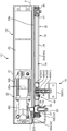
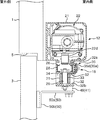
図1から図3に示すように、第1実施形態に係るドア開閉装置10は、建築物の壁体1の室内側の面に取り付けられて、ドア(開き戸)3を室外側に向けて開放するための開閉装置である。ドア開閉装置10は、建築物の壁体1における室内側の壁面に固定されるドアエンジン部12と、このドアエンジン部12の下側に配設されている直動機構14と、直動機構14の動きをドア3に伝動させるための連結機構16と、連結機構16の移動方向を規定するためのガイド構成部18と、を備えている。図2に示すように、ドアエンジン部12は、壁体1に対して室内側に配置され、直動機構14、連結機構16及びガイド構成部18は、ドア3に対して室内側に配置されている。
図1から図3に示すように、第1実施形態に係るドア開閉装置10は、建築物の壁体1の室内側の面に取り付けられて、ドア(開き戸)3を室外側に向けて開放するための開閉装置である。ドア開閉装置10は、建築物の壁体1における室内側の壁面に固定されるドアエンジン部12と、このドアエンジン部12の下側に配設されている直動機構14と、直動機構14の動きをドア3に伝動させるための連結機構16と、連結機構16の移動方向を規定するためのガイド構成部18と、を備えている。図2に示すように、ドアエンジン部12は、壁体1に対して室内側に配置され、直動機構14、連結機構16及びガイド構成部18は、ドア3に対して室内側に配置されている。
ドアエンジン部12は、壁体1の開口部5の上縁に沿って開口幅方向に延びる姿勢で配設されるケース21を備えている。このケース21には、主としてブラシレスモータ22及びドアコントローラ23が収納されている。
ブラシレスモータ22は、磁石位置検知素子であるホール素子22aを有しており、ホール素子22aから出力される信号に応じた信号を出力する。すなわち、ブラシレスモータ22では、例えばロータ(図示省略)に磁石が固定される一方、ステータ(図示省略)に多数のホール素子22aが周方向に配設されている。そして、ロータの回転角度に応じてホール素子22aから出力される信号が変化する。なお、このブラシレスモータ22は直流(DC)ブラシレスモータあるが、交流(AC)ブラシレスモータを使用することも可能である。
ブラシレスモータ22から出力された信号はドアコントローラ23が受信し、ドアコントローラ23は、この受信した信号に応じてブラシレスモータ22の駆動制御を行う。
本実施形態では、ブラシレスモータ22としてギアードモータが用いられている。すなわち、ブラシレスモータ22には、モータ本体22bと減速機構22cとが設けられていて、モータ本体22bの回転数を減速機構22cで減速した回転数でブラシレスモータ22の出力軸22dを回転させる。ブラシレスモータ22は、出力軸22dが下を向いた姿勢でケース21に固定されている。
直動機構14は、駆動輪部である駆動プーリ26と、従動輪部であるアイドラプーリ27と、駆動プーリ26及びアイドラプーリ27に巻き掛けられるベルト(巻き掛け部材)28とを備えている。駆動プーリ26は、貫通孔が形成されていて、ケース21よりも下方の位置でブラシレスモータ22の出力軸22dに外嵌されて、当該出力軸22dに固定されている。アイドラプーリ27は軸受ブラケット30を介して後述のレール部材35に回転自在に取り付けられている。アイドラプーリ27の回転軸は駆動プーリ26の回転軸と平行となっている。すなわち、駆動プーリ26及びアイドラプーリ27は、回転軸が鉛直方向に延びる姿勢となっている。
ケース21の下側には、駆動プーリ26の軸部材29を支持するための支持ブラケット32が配置されている。支持ブラケット32は、出力軸22dの近傍においてケース21の下面に接触する接触部32aと、この接触部32aの下方で水平(接触部32aと平行)に配置される支持部32bとを備えている。接触部32aはケース21の外側に配設されている。ガイド構成部18のレール部材35(後述)とケース21との間に接触部32aが挟み込まれる構成とすることにより、レール部材35とケース21の下面との間には間隙が形成されている。なお、支持ブラケット32は、ケース21に固定されていてもよく、あるいは接触部32aが壁体1に固定されていてもよい。
支持部32bと駆動プーリ26との間には、出力軸22dと同軸上に配置されるとともに支持部32bに固定されている前記軸部材29が設けられている。この軸部材29は、下側の小径部において支持部32bに固定されている。軸部材29の大径部における径方向外側には、スペーサ部材31の大径円筒部が配設されている。スペーサ部材31は後述のレール部材35と結合されている。このため、スペーサ部材31は、レール部材35の回動に伴い、支持部32bに対して回動可能となっている。また、軸部材29とスペーサ部材31の大径円筒部との間には、薄肉円筒状のブッシュ33が配設されており、スペーサ部材31は、ブッシュ33を介して軸部材29に対して回動可能となっている。また、駆動プーリ26と軸部材29の段付き部との間にベアリング34が設けられており、駆動プーリ26は軸部材29に対して回転自在となっている。
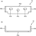
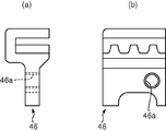
連結機構16は、ベルト28と一体的に移動する連結部40と、この連結部40に対して回動可能なドア結合部材41とを備えている。連結部40は、ベルト28に取り付けられる定着部43と、定着部43に対して回転可能に構成されている転動体44とを備えている。定着部43は、板金からなる取付部材45(図4(a)(b)参照)と、この取付部材45に固定されるとともにベルト28に固定されるクランプ金具46(図5(a)(b)参照)と、取付部材45に固定されるとともに上下方向に延びるピン状の軸部47とを備えている。
取付部材45は、図4(a)(b)に示すように、平板状の板金を曲げ加工したものであり、一方向に長い形状の底部45aと、底部45aの両端からそれぞれ立ち上がる側部45bとを一体的に有する。底部45aの中央部には、軸部47を挿通可能な貫通孔45cが形成されている。また底部45aには、クランプ金具46の位置調整のための長孔45dが形成されている。
クランプ金具46は、2つ設けられており、図5(a)(b)に示すように、各クランプ金具46には、取付部材45の長孔45dに挿通された締結具(ボルト)を締結するための締結孔46aが設けられている。そして、各クランプ金具46は、転動体44の両側に位置するように配置されて取付部材45に締結されている。
一方のクランプ金具46はベルト28の一端部に固定され、他方のクランプ金具46はベルト28の他端部に固定されている。すなわち、ベルト28は、後述するようにガイド部35aの2つの壁部35c,35dのうちの一方の壁部35dがベルト28の外側に位置し、かつこの壁部35dに沿って転動体44が転動するため、ベルト28は無端状部材ではなく、途中で途切れたものが用いられている。そして、ベルト28の両端部にそれぞれクランプ金具46が取り付けられるとともに、両クランプ金具46は取付部材45に固定されている。ベルト28及び取付部材45が互いに結合されることによって、無端状の部材が構成され、この無端状の部材が駆動プーリ26及びアイドラプーリ27に掛け渡されている。なお、ベルト28の両端部は、無端状部材のうち、室内側(ドア3からより離れた側)の直線部分に位置しており、取付部材45は、プーリ26,27の軸心よりもドア3から離れたところを往復直線運動する。
軸部47は、ボルトによって取付部材45に固定されている。軸部47のうち、取付部材45の内側(上側)に位置している部分には、転動体44が回転自在に外嵌されている。軸部47のうち、取付部材45の外側(下側)に位置している部分には、ドア結合部材41が回動可能に結合されている。
ドア結合部材41は、ドア3に結合される部材であり、定着部43の軸部47に外嵌される筒部材49と、この筒部材49に固定される吊持部材50とを備えている。ドア結合部材41が定着部43の軸部47(連結部40)に対して鉛直軸回りに回動可能となっているので、連結部40の移動方向に対してドア3の向きが変化することを妨げることはない。
吊持部材50は、筒部材49に固定される横部50aと、この横部50aの端部から下方に延出さる垂下部50bとを一体的に有し、この垂下部50bをドア3に締結することができる。吊持部材50が水平方向に張り出す横部50aを備えているので、連結部40の直線移動方向がドア3の回動中心からずれた状態でドア開閉装置10を配設することができる。なお、吊持部材50の横部50aは、建築物の壁体1の厚みに応じた長さのものを適宜選択すればよい(図7(a)(b)参照)。
ガイド構成部18は、直動機構14の連結部40を案内するためのものであり、直動機構14と同様にドアエンジン部12の下側に配設されている。ガイド構成部18は、ガイド部35aと本体部35bとが一体的に設けられたレール部材35を備えている。図1に示すように、レール部材35は一方向に長い形状のものであり、その一端部において、駆動プーリ26の軸受部材31と結合されている。このため、レール部材35は、出力軸22d及び駆動プーリ26と同軸回りに回動可能となっている。なお、スペーサ部材31は、レール部材35の本体部35bと締結される結合部材52と溶接されている。レール部材35の他端部において、本体部35bには、アイドラプーリ27が取り付けられており、レール部材35は本体部35bが水平となり、ガイド部35aが本体部35bの幅方向両側から下側に突出する形態で配設されている。そして、ガイド部35aは、レール部材35の幅方向に間隔をおいて配置された2つの壁部35c,35dを備えている。
レール部材35は、図6(a)(b)にも示すように、一方の壁部35cにおける両端部が矩形状に切り欠かれた構成となっている。この切欠き部35eは、図3に示すように、駆動プーリ26及びアイドラプーリ27の一部がガイド部35aの外側に突出した状態で、駆動プーリ26の軸受部材31及びアイドラプーリ27の軸受ブラケット30を配設可能にするために設けられている。アイドラプーリ27の軸受ブラケット30は、ボルトによってもう一方の壁部35dに締結されている。
ベルト28は、駆動プーリ26及びアイドラプーリ27に巻き掛けられているが、ベルト28の直線部分のうちの一方は、2つの壁部35c,35dの間に位置し、他方は壁部35cの外側に位置している。そして、連結部40の転動体44は、2つの壁部35c,35dの間に位置しており、両壁部35c,35dの内面に沿って転動可能となっている。転動体44の回転中心、すなわち連結部40の中心は、ベルト28に対して駆動プーリ26の回転軸及びアイドラプーリ27の回転軸を結んだ線の側にオフセットされている。なお、レール部材35の本体部35bには、図6(a)に示すように、出力軸22dを挿通させるための挿通部35fが切欠き形成されている。
ここで、第1実施形態のドア開閉装置10によるドア3の開閉動作について、図7(b)を参照しつつ説明する。図7(b)では、壁体1の開口部5を閉じた閉じ位置にあるドア3を実線で示し、開口部5が開放された開き位置にあるドア3を仮想線で示している。この開き位置にある状態では、吊持部材50を便宜上1つの直線で示している。また、同図において、ドア3の回動中心をOとして図示している。この回動中心Oは、ドア3が壁体1に対してスイング開閉できるようにする蝶番(ヒンジ)の芯位置を表しており、閉じ位置にあるドア3の軸元側端部の室外側の位置に設定されている。
ドア3が開口部5を閉じている位置(閉じ位置)にあるときには、連結部40が駆動プーリ26に比較的近い位置に位置づけられている。そして、ドア3を開放動作するには、ブラシレスモータ22が駆動されて駆動プーリ26が回転する。これにより、ベルト28及び連結部40がアイドラプーリ27(戸先側)に向かって移動する。このとき、連結部40の転動体44がレール部材35の一対の壁部35c,35dに沿って転動するので、連結部40はまっすぐに移動する。
連結部40には、ドア結合部材41が結合されていて、転動体44の中心とドア3との位置関係が固定されているので、連結部40を戸先側に向かって移動させる力は、ドア結合部材41が結合されたドア3を回動中心O回りに回動させるモーメントとしてドア3に作用する。したがって、連結部40の移動に伴って、ドア3は室外側に向けて開き動作し、壁体1の開口部5が開放される。このとき、ドア3が全開する間に、ブラシレスモータ22の出力軸22dは複数回転する。したがって、ドアコントローラ23によって正確に位置制御することができる。ドア3を開き位置から閉じ位置に動作させる場合には、ブラシレスモータ22の出力軸22dを反対向きに回転させればよい。
なお、図7(a)のように吊持部材50の水平方向の長さが長い場合でも同様に動作するが、連結部40の移動ストロークとドア3の回転角度との比が異なっている。
以上説明したように、第1実施形態のドア開閉装置10では、駆動プーリ26の回転に伴い、ベルト28とドア3を連結する連結機構16が一方向に移動する間に、ドア3を閉じ位置から全開位置まで、あるいは全開位置から閉じ位置まで移動させることができる。このとき、コントローラ23は、ホール素子22aから出力される信号に基づいてブラシレスモータ22の駆動制御を行う。したがって、高分解能のエンコーダを用いることなく、ドア3の開閉制御を行うことができる。このため、装置全体をコンパクトなものにすることができる。しかも、第1実施形態のドア開閉装置10では、直動機構14の駆動プーリ26は、連結機構16が一方向に移動する間に複数回転するので、ブラシレスモータ22と駆動プーリ26との間に高減速比の減速機を用いなくても、ドア3の開閉制御又は停止位置制御を可能となる。また、モータ22の回転数を直動機構14によって減速する構成なので、歯車による高減速比の減速機を用いる場合に必要となるクラッチも基本的には不要となる。
また第1実施形態では、ベルト駆動方式となっているので、静粛なドア開閉装置10となっている。
また第1実施形態では、駆動プーリ26の回転によってベルト28が走行することに伴い、連結部40はガイド部35aに案内されながら移動する。したがって、駆動プーリ26の回動によってドア3の移動方向を安定させることができる。
また第1実施形態では、駆動プーリ26の回転によってベルト28が走行することに伴い、連結部40はレール部材35のガイド部35aに案内されながら移動する。このときドア結合部材41が連結部40に対して回動しながら、連結部40はベルト28と一緒に移動する。これにより、ドア3をスイング開閉させることができる。
さらに第1実施形態では、連結機構16を案内するためのガイド部35aを有するガイド構成部18がドアエンジン部12に対して回動可能な構成となっているので、ドア結合部材41がドア3に固定された状態でもドア3をスイング開閉させることができる。
また第1実施形態では、駆動プーリ26及びアイドラプーリ27が鉛直軸回りに回転する構成となっているので、直動機構14及びガイド構成部18の上下方向の幅(高さ)をより小さくすることができる。
また第1実施形態では、連結部40の転動体44が定着部43に対して回転可能であり、連結部40がガイド部35aに案内される際に壁部35c,35dに沿って転動するので、移動抵抗を低減することができる。
また第1実施形態では、連結部40の中心が駆動プーリ26の回転軸及びアイドラプーリ27の回転軸を結んだ線に対してオフセットされているので、奥行き方向にコンパクトな構成となる。
(第2実施形態)
第1実施形態では、ドア3が室外側に向かって開放される外開きのスイングドア3の開閉装置としたが、第2実施形態は、図8~図10(b)に示すように、ドア3が室内側に向かって開放される内開きのスイングドア用の開閉装置である。尚、ここでは第1実施形態と異なる部分の説明のみを行い、第1実施形態と同じ構成要素には同じ符号を付して、その詳細な説明を省略する。
第1実施形態では、ドア3が室外側に向かって開放される外開きのスイングドア3の開閉装置としたが、第2実施形態は、図8~図10(b)に示すように、ドア3が室内側に向かって開放される内開きのスイングドア用の開閉装置である。尚、ここでは第1実施形態と異なる部分の説明のみを行い、第1実施形態と同じ構成要素には同じ符号を付して、その詳細な説明を省略する。
図8に示すように、第2実施形態では、ガイド構成部18がドアエンジン部12のケース21に対して固定されている。具体的には、ガイド構成部18のレール部材35には、ボルト(締結具)55を挿通させるための挿通孔が本体部35bに形成されている。第2実施形態では支持ブラケット32及び駆動プーリ26の軸受部材31が省略されていて、レール部材35の本体部35bがケース21の下面に接触している。そして、ケース21内には、ガイド構成部18をドアエンジン部12のケース21に対して固定する固定具56が設けられている。この固定具56は、ケース21の下側から挿通孔に挿通されたボルト55が螺合されるねじ孔56aと、固定具56をケース21の側面に固定するためのボルト(図示省略)を螺合させるねじ孔56bとが形成されている。これにより、ガイド構成部18がドアエンジン部12に対して固定されている。なお、ドアエンジン部12に対してガイド構成部18を固定するための部位は、上記以外に別途設けられていても良い。例えば駆動プーリ26を挟んでアイドラプーリ27とは反対側をドアエンジン部12に固定するようにしても良い。
図9に示すように、ドア結合部材41は、ドア3に回動可能に結合されるとともに連結部40に回動可能に連結されるリンク部材58を備えている。リンク部材58は、水平方向に延びる姿勢で配設されて、定着部43と吊持部材50とを連結するための部材であり、リンク部材58の一端部は、定着部43の軸部47に回動可能に外嵌されている。したがって、第2実施形態のドア結合部材41では、筒部材49が省略されている。つまり、リンク部材58の一端部は、第1実施形態におけるドア結合部材41の筒部材49と同様に定着部43の軸部47に外嵌できるので、外開き用に構成するか、内開き用に構成するかにより、筒部材49とリンク部材58とを選択的に使用することができる。
また、リンク部材58の他端部は、吊持部材50の横部50aから上方に延びるピン部50cに回動可能に外嵌されている。ピン部50cは、ボルト(締結具)によって横部50aに固定されている。
リンク部材58は吊持部材50の横部50a及びドア3よりも上方に位置しているため、ドア3が室内側に開放されるときでも、リンク部材58が吊持部材50及びドア3と干渉することはない。なお、ドアエンジン部12は第1実施形態と同様に壁体1の室内側に配置されており、ドアエンジン部12、連結部40及びガイド構成部18は、第1実施形態と異なり、ドア3よりも上方に配置されている。
ここで、第2実施形態のドア開閉装置10によるドア3の開閉動作について、図10(b)を参照しつつ説明する。なお、図10(a)は吊持部材50の横部50aの長さの異なる場合を示しているが、動作については図10(b)の構成と同じである。図10(a)(b)では、リンク部材58を便宜上直線で示しており、また、ドア3が開き位置にあるときの吊持部材50も便宜上直線で示している。なお、図10(a)に示すドア開閉装置10は、図11に示すように、吊持部材50の横部50aがドア3から定着部43の軸部47を超える位置まで延びる長い形状に形成された開閉装置10を示すものである。
第2実施形態では、蝶番の芯位置であるドア3の回動中心Oは、閉じ位置にあるドア3の軸元側端部に対して室内側の位置に設定されている。
ドア3が開口部5を閉じている位置(閉じ位置)にあるときには、連結部40がアイドラプーリ27に比較的近い位置に位置づけられている。そして、ドア3を開放動作するには、ブラシレスモータ22が駆動されて駆動プーリ26が回転する。これにより、ベルト28及び連結部40が駆動プーリ26(軸元側)に向かって移動する。このとき、連結部40の軸部47はリンク部材58によってドア3との距離が一定に維持されているので、連結部40の直線運動に連動してドア3が開き動作する。これにより、壁体1の開口部5が開放される。ドア3を開き位置から閉じ位置に動作させる場合には、ブラシレスモータ22の出力軸22dを反対向きに回転させればよい。
なお、図10(a)のように吊持部材50の水平方向の長さが長い場合でも同様に動作するが、連結部40の移動ストロークとドア3の回転角度との比が異なっている。
したがって、第2実施形態では、ドア結合部材41が、ガイド部35aに案内される連結部40に対して回動可能なリンク部材58を備えており、このリンク部材58がドア3に対して回動可能となっているので、ベルト28の走行に伴って連結部40が移動すると、リンク部材58は、それに伴って回動する。これにより、ドア3をスイング開閉させることができる。
また、第2実施形態では、レール部材35をドアエンジン部12に固定するための固定具56を第1実施形態のドア開閉装置10に追加する一方で、筒部材49に代えてリンク部材58を使用している。つまり、第1実施形態の外開き用のドア開閉装置10と、第2実施形態の内開き用のドア開閉装置10とにおいて、主要部品の共用化を図ることができるようになっている。
なお、その他の構成、作用及び効果はその説明を省略するが前記第1実施形態と同様である。
(第3実施形態)
第1及び第2実施形態は、開き戸用のドア開閉装置10としたが、図12(a)(b)に示すように、第3実施形態は引き戸用のドア開閉装置10としている。尚、ここでは第2実施形態と異なる部分の説明のみを行い、第2実施形態と同じ構成要素には同じ符号を付して、その詳細な説明を省略する。
第1及び第2実施形態は、開き戸用のドア開閉装置10としたが、図12(a)(b)に示すように、第3実施形態は引き戸用のドア開閉装置10としている。尚、ここでは第2実施形態と異なる部分の説明のみを行い、第2実施形態と同じ構成要素には同じ符号を付して、その詳細な説明を省略する。
第3実施形態のドア開閉装置10では、レール部材35がドアエンジン部12よりも長く形成されており、このレール部材35は、ドアエンジン部12のケース21に固定される一方で、建築物の壁体1又は壁体1に固定された固定体に固定用ブラケット61によって固定されている。
レール部材35は、アルミニウム製又はアルミニウム合金製であるため、開口部5の幅に応じた長さに切断して設置現場で調整することができる。また、第2実施形態と同様にドアエンジン部12のケース21と同じ長さに切断すれば、開き戸用のドア開閉装置10に用いられるレール部材35にもなる。
第3実施形態では、リンク部材58が省略されており、定着部43の軸部47が吊持部材50に締結されている。つまり、吊持部材50は、一端部がドア3に固定されるとともに他端が連結部40に固定されるブラケットである。軸部47に吊持部材50を締結するには、軸部47の先端(下端)にねじ孔を形成しておき、吊持部材50の横部50aの挿通孔に挿通されたボルトを軸部47のねじ孔に螺合させるようにすればよい。
したがって、第1~第3実施形態のドア開閉装置10では、一端部がドア3に固定されるとともに他端が連結部40に回動可能に結合される筒部材49(第1ブラケット)と、リンク部材58と、一端部がドア3に固定されるとともに他端が連結部40に固定される吊持部材50(第2ブラケット)と、を選択的に使用可能となっている。すなわち、筒部材49を用いてドア3と連結部40とを連結する構成とすれば、外開き用の開き戸に用いられるドア開閉装置10とすることができ、また、リンク部材58を用いてドア3と連結部40とを連結する構成とすれば、内開き用の開き戸に用いられるドア開閉装置10とすることができ、また、吊持部材50を用いてドア3と連結部40とを連結する構成とすれば、引き戸用のドア開閉装置10とすることができる。したがって、コストダウンを図ることができるとともに、在庫管理の負担を軽減することができる。
また、第2及び第3実施形態のドア開閉装置10では、リンク部材58と吊持部材50(ブラケット)とを選択的に取り付けることができるので、内開き用のドア開閉装置10と引き戸用のドア開閉装置10とで、主要部品を共用化できる。
また、第3実施形態では、レール部材35がアルミニウム合金製の押し出し材であるので、施工現場において、開口幅やドア3の開閉タイプに応じて、ガイド部35a及び本体部35bを切断することができる。この結果、部品点数が増大することを抑制しつつも、多様な施工現場に対応することができる。
(その他の実施形態)
なお、本発明は、前記実施形態に限られるものではなく、その趣旨を逸脱しない範囲で種々変更、改良等が可能である。例えば、前記各実施形態では、巻き掛け部材としてベルト28を用いたが、チェーン又はワイヤとしてもよい。
なお、本発明は、前記実施形態に限られるものではなく、その趣旨を逸脱しない範囲で種々変更、改良等が可能である。例えば、前記各実施形態では、巻き掛け部材としてベルト28を用いたが、チェーン又はワイヤとしてもよい。
また前記各実施形態では、ブラシレスモータ22としてギアードモータが用いられた構成について説明したがこれに限られるものではなく、減速機構を内蔵しないタイプのブラシレスモータとしてもよい。
また、レール部材35には、図11に示すように、プーリ及びベルト28を覆うようにレールカバー63を設けるようにしてもよい。このレールカバー63は、レール部材35の長手方向に長い形状の部材であり、壁部35c,35dの外側に位置するベルト28及びプーリを覆うためのものである。
[実施の形態の概要]
前記実施形態をまとめると、以下の通りである。
前記実施形態をまとめると、以下の通りである。
(1) 前記実施形態によるドア開閉装置では、駆動輪部の回転に伴い、巻き掛け部材とドアを連結する連結機構が一方向に移動する間に、ドアを閉じ位置から全開位置まで、あるいは全開位置から閉じ位置まで移動させることができる。このとき、コントローラは、ブラシレスモータの回転制御のために内蔵されている磁石位置検知素子から出力される信号を流用し、これに基づいてブラシレスモータの速度ないし位置制御を行う。しかも、このドア開閉装置では、直動機構の駆動輪部は、連結機構が一方向に移動する間に複数回転するので、上記磁石位置検知素子が発生するパルス数を増加させるためにブラシレスモータと駆動輪部との間に高減速比の減速機を用いなくても、ドアの開閉制御又は停止位置制御が可能となる。したがって、高価な高分解能のエンコーダを、別に用いることなく、ドアの開閉制御を行うことができる。このため、装置全体をコンパクトなものにすることができる。また、モータの回転数を直動機構によって減速する構成なので、歯車による高減速比の減速機を用いる場合に、手動で容易に開閉させるために必要となるクラッチも不要となる。
(2) 前記駆動輪部及び前記従動輪部は、プーリであり、前記巻き掛け部材は、ベルトであるのが好ましい。この態様では、静粛なドア開閉装置となる。
(3) 前記ドア開閉装置は、前記連結機構の移動方向に沿って延びるガイド部と、前記ガイド部と一体的に設けられるとともに前記従動輪部が取り付けられる本体部とを有するガイド構成部を備えているのが好ましく、この場合、前記連結機構は、前記巻き掛け部材に連結されるとともに前記ガイド部に案内される連結部を備えているのが好ましい。
この態様では、駆動輪部の回転によって巻き掛け部材が走行することに伴い、連結部はガイド部に案内されながら移動する。したがって、駆動輪部の回動によってドアの移動方向を安定させることができる。
(4) 前記連結機構は、前記連結部に回動可能に連結されるとともに前記ドアに結合されるドア結合部材を備え、当該連結機構は、前記巻き掛け部材の走行に伴って前記ドアがスイング開閉するように動作するようにしてもよい。
この態様では、駆動輪部の回転によって巻き掛け部材が走行することに伴い、連結部はガイド部に案内されながら移動する。このときドア結合部材が連結部に対して回動しながら、連結部は巻き掛け部材と一緒に移動する。これにより、ドアをスイング開閉させることができる。したがって、この態様のドア開閉装置では、開き戸(スイングドア)用のドア開閉装置となる。
(5) このドア開閉装置において、前記ドア結合部材は、前記ドアに固定されており、前記ガイド構成部は、前記駆動輪部と同軸状に回動可能に構成され、前記巻き掛け部材の走行に伴って回動する構成であってもよい。
この態様では、連結機構を案内するためのガイド部を有するガイド構成部が回動する構成となっているので、ドア結合部材がドアに固定された状態でもドアをスイング開閉させることができる。
(6) 前記駆動輪部及び前記従動輪部は、回転軸が鉛直方向になるように配置されていてもよく、前記ガイド部は、前記巻き掛け部材の一方の直線部分を挟んで対向する2つの壁部を備え、前記連結部は、前記2つの壁部の間に位置していてもよい。
この態様では、駆動輪部及び従動輪部が鉛直軸回りに回転する構成となっているので、直動機構及びガイド機構の上下方向の幅(高さ)をより小さくすることができる。
(7) このドア開閉装置において、前記連結部は、前記巻き掛け部材に定着される定着部と、前記定着部に対して回転可能であり、前記2つの壁部に沿って転動する転動体とを備えていてもよい。
この態様では、連結部の転動体が定着部に対して回転可能であり、連結部がガイド部に案内される際に壁部に沿って転動するので、移動抵抗を低減することができる。
(8) 前記連結部の中心は、前記巻き掛け部材に対して、前記駆動輪部の回転軸及び前記従動輪部の回転軸を結んだ線の側にオフセットされていてもよい。この態様では、前記巻き掛け部材が対向する空間に、前記連結部の一部を配置できるため、前記連結部が前記巻き掛け部材に対して前記駆動輪部の回転軸及び前記従動輪部の回転軸を結んだ線とは反対側に突出する量が少なくなり、これにより、奥行き方向にコンパクトな構成となる。
(9) 前記ドア開閉装置において、前記ブラシレスモータが固定されるケースを備えており、前記ガイド構成部は、前記ケースに対して固定されており、前記ドア結合部材は、前記ドアに回動可能に結合されるとともに前記連結部に回動可能に連結されるリンク部材を備えていてもよい。
この態様では、ドア結合部材が、ガイド部に案内される連結部に対して回動可能なリンク部材を備えており、このリンク部材がドアに対して回動可能となっているので、巻き掛け部材の走行に伴って連結部が移動すると、リンク部材は、それに伴って回動する。これにより、ドアをスイング開閉させることができる。
(10)前記ドア開閉装置において、前記連結機構の移動方向に沿って延びるガイド部と、前記ガイド部と一体的に設けられるとともに前記従動輪部が取り付けられる本体部とを有するガイド構成部と、前記ブラシレスモータが固定されるケースと、を備えており、前記ガイド構成部は、前記ケースに対して固定されている場合には、前記ドアに回動可能に結合されるとともに前記連結部に回動可能に連結されるリンク部材と、一端部が前記ドアに固定されるとともに他端が前記連結部に固定されるブラケットと、を選択的に使用可能であってもよい。
この態様では、開き戸(スイングドア)用のドア開閉装置と、引き戸用のドア開閉装置とで、主要な構成部品を共通化することができる。すなわち、リンク部材を用いてドアと連結部とを連結する構成とすれば、開き戸用のドア開閉装置とすることができる一方、ブラケットを用いてドアと連結部とを連結する構成とすれば、引き戸用のドア開閉装置とすることができる。したがって、コストダウンを図ることができるとともに、在庫管理の負担を軽減することができる。
(11)前記ドア開閉装置において、前記連結機構の移動方向に沿って延びるガイド部と、前記ガイド部と一体的に設けられるとともに前記従動輪部が取り付けられる本体部とを有するガイド構成部を備えており、前記ガイド構成部の回動を阻止する固定具が着脱可能に設けられている場合には、前記ドアに回動可能に結合されるとともに前記連結部に回動可能に連結されるリンク部材と、一端部が前記ドアに固定されるとともに他端が前記連結部に回動可能に結合される第1ブラケットと、一端部が前記ドアに固定されるとともに他端が前記連結部に固定される第2ブラケットと、を選択的に使用可能であってもよい。
この態様では、2タイプの開き戸(スイングドア)用のドア開閉装置と、引き戸用のドア開閉装置とで、主要な構成部品を共通化することができる。すなわち、リンク部材を用いてドアと連結部とを連結する構成とすれば、第1のタイプの開き戸用ドア開閉装置とすることができ、また、第1ブラケットを用いてドアと連結部とを連結する構成とすれば、第2のタイプの開き戸用ドア開閉装置とすることができ、また、ブラケットを用いてドアと連結部とを連結する構成とすれば、引き戸用のドア開閉装置とすることができる。したがって、コストダウンを図ることができるとともに、在庫管理の負担を軽減することができる。
(12)このドア開閉装置において、前記ガイド構成部は、アルミニウム製又はアルミニウム合金製であってもよい。この態様では、施工現場において、開口幅やドアの開閉タイプに応じて、ガイド部及び本体部を切断することができるので、部品点数が増大することを抑制しつつも、多様な施工現場に対応することができる。
10 ドア開閉装置
12 ドアエンジン部
14 直動機構
16 連結機構
18 ガイド構成部
21 ケース
22 ブラシレスモータ
22a ホール素子
22d 出力軸
23 ドアコントローラ
26 駆動プーリ
27 アイドラプーリ
28 ベルト
35 レール部材
35a ガイド部
35b 本体部
35c 壁部
35d 壁部
40 連結部
41 ドア結合部材
43 定着部
44 転動体
45 取付部材
46 クランプ金具
47 軸部
49 筒部材
50 吊持部材
50a 横部
50b 垂下部
50c ピン部
56 固定具
58 リンク部材
12 ドアエンジン部
14 直動機構
16 連結機構
18 ガイド構成部
21 ケース
22 ブラシレスモータ
22a ホール素子
22d 出力軸
23 ドアコントローラ
26 駆動プーリ
27 アイドラプーリ
28 ベルト
35 レール部材
35a ガイド部
35b 本体部
35c 壁部
35d 壁部
40 連結部
41 ドア結合部材
43 定着部
44 転動体
45 取付部材
46 クランプ金具
47 軸部
49 筒部材
50 吊持部材
50a 横部
50b 垂下部
50c ピン部
56 固定具
58 リンク部材
Claims (12)
- ドアを開閉動作するためのドア開閉装置であって、
磁石位置検知素子を有するブラシレスモータと、
前記磁石位置検知素子から出力される信号に応じて前記ブラシレスモータの駆動制御を行うコントローラと、
前記ブラシレスモータの回転駆動力を受ける駆動輪部と、前記駆動輪部の回転軸と平行な軸回りに回転可能な従動輪部と、前記駆動輪部及び前記従動輪部に巻き掛けられる巻き掛け部材と、を有する直動機構と、
前記巻き掛け部材に連結されるとともに、ドアの動きを前記巻き掛け部材に連動させるための連結機構とを備え、
前記直動機構は、前記連結機構が前記巻き掛け部材に連動して一方向に移動する間に前記駆動輪部が複数回転する設定となっているドア開閉装置。 - 請求項1に記載のドア開閉装置において、
前記駆動輪部及び前記従動輪部は、プーリであり、
前記巻き掛け部材は、ベルトであるドア開閉装置。 - 請求項1又は2に記載のドア開閉装置において、
前記連結機構の移動方向に沿って延びるガイド部と、前記ガイド部と一体的に設けられるとともに前記従動輪部が取り付けられる本体部とを有するガイド構成部を備え、
前記連結機構は、前記巻き掛け部材に連結されるとともに前記ガイド部に案内される連結部を備えているドア開閉装置。 - 請求項3に記載のドア開閉装置において、
前記連結機構は、前記連結部に回動可能に連結されるとともに前記ドアに結合されるドア結合部材を備え、当該連結機構は、前記巻き掛け部材の走行に伴って前記ドアがスイング開閉するように動作するドア開閉装置。 - 請求項4に記載のドア開閉装置において、
前記ドア結合部材は、前記ドアに固定されており、
前記ガイド構成部は、前記駆動輪部と同軸状に回動可能に構成され、前記巻き掛け部材の走行に伴って回動するドア開閉装置。 - 請求項3、4又は5に記載のドア開閉装置において、
前記駆動輪部及び前記従動輪部は、回転軸が鉛直方向になるように配置され、
前記ガイド部は、前記巻き掛け部材の一方の直線部分を挟んで対向する2つの壁部を備え、
前記連結部は、前記2つの壁部の間に位置しているドア開閉装置。 - 請求項6に記載のドア開閉装置において、
前記連結部は、前記巻き掛け部材に定着される定着部と、前記定着部に対して回転可能であり、前記2つの壁部に沿って転動する転動体とを備えているドア開閉装置。 - 請求項6又は7に記載のドア開閉装置において、
前記連結部の中心は、前記巻き掛け部材に対して、前記駆動輪部の回転軸及び前記従動輪部の回転軸を結んだ線の側にオフセットされているドア開閉装置。 - 請求項4に記載のドア開閉装置において、
前記ブラシレスモータが固定されるケースを備えており、
前記ガイド構成部は、前記ケースに対して固定されており、
前記ドア結合部材は、前記ドアに回動可能に結合されるとともに前記連結部に回動可能に連結されるリンク部材を備えているドア開閉装置。 - 請求項1に記載のドア開閉装置において、
前記連結機構の移動方向に沿って延びるガイド部と、前記ガイド部と一体的に設けられるとともに前記従動輪部が取り付けられる本体部とを有するガイド構成部と、
前記ブラシレスモータが固定されるケースと、を備えており、
前記ガイド構成部は、前記ケースに対して固定されており、
前記ドアに回動可能に結合されるとともに前記連結部に回動可能に連結されるリンク部材と、一端部が前記ドアに固定されるとともに他端が前記連結部に固定されるブラケットと、を選択的に使用可能であるドア開閉装置。 - 請求項1に記載のドア開閉装置において、
前記連結機構の移動方向に沿って延びるガイド部と、前記ガイド部と一体的に設けられるとともに前記従動輪部が取り付けられる本体部とを有するガイド構成部を備えており、
前記ガイド構成部の回動を阻止する固定具が着脱可能に設けられ、
前記ドアに回動可能に結合されるとともに前記連結部に回動可能に連結されるリンク部材と、一端部が前記ドアに固定されるとともに他端が前記連結部に回動可能に結合される第1ブラケットと、一端部が前記ドアに固定されるとともに他端が前記連結部に固定される第2ブラケットと、を選択的に使用可能であるドア開閉装置。 - 請求項10又は11に記載のドア開閉装置において、
前記ガイド構成部は、アルミニウム製又はアルミニウム合金製であるドア開閉装置。
Priority Applications (1)
| Application Number | Priority Date | Filing Date | Title |
|---|---|---|---|
| PCT/JP2010/002846 WO2011132219A1 (ja) | 2010-04-20 | 2010-04-20 | ドア開閉装置 |
Applications Claiming Priority (1)
| Application Number | Priority Date | Filing Date | Title |
|---|---|---|---|
| PCT/JP2010/002846 WO2011132219A1 (ja) | 2010-04-20 | 2010-04-20 | ドア開閉装置 |
Publications (1)
| Publication Number | Publication Date |
|---|---|
| WO2011132219A1 true WO2011132219A1 (ja) | 2011-10-27 |
Family
ID=44833788
Family Applications (1)
| Application Number | Title | Priority Date | Filing Date |
|---|---|---|---|
| PCT/JP2010/002846 Ceased WO2011132219A1 (ja) | 2010-04-20 | 2010-04-20 | ドア開閉装置 |
Country Status (1)
| Country | Link |
|---|---|
| WO (1) | WO2011132219A1 (ja) |
Cited By (2)
| Publication number | Priority date | Publication date | Assignee | Title |
|---|---|---|---|---|
| CN107923922A (zh) * | 2015-07-24 | 2018-04-17 | 塞弗德公司 | 分子诊断化验系统 |
| CN108915461A (zh) * | 2018-03-22 | 2018-11-30 | 天钺电子(东莞)有限公司 | 置地型闭门器系统及使用其之侦测方法 |
Citations (3)
| Publication number | Priority date | Publication date | Assignee | Title |
|---|---|---|---|---|
| JPH0593485A (ja) * | 1990-11-09 | 1993-04-16 | Ryoichi Oguchi | ドア自動開閉装置 |
| JP2001182430A (ja) * | 1999-12-28 | 2001-07-06 | Fujita Corp | 窓の開閉装置 |
| JP2009155826A (ja) * | 2007-12-25 | 2009-07-16 | Panasonic Electric Works Co Ltd | 自動ドア装置 |
-
2010
- 2010-04-20 WO PCT/JP2010/002846 patent/WO2011132219A1/ja not_active Ceased
Patent Citations (3)
| Publication number | Priority date | Publication date | Assignee | Title |
|---|---|---|---|---|
| JPH0593485A (ja) * | 1990-11-09 | 1993-04-16 | Ryoichi Oguchi | ドア自動開閉装置 |
| JP2001182430A (ja) * | 1999-12-28 | 2001-07-06 | Fujita Corp | 窓の開閉装置 |
| JP2009155826A (ja) * | 2007-12-25 | 2009-07-16 | Panasonic Electric Works Co Ltd | 自動ドア装置 |
Cited By (9)
| Publication number | Priority date | Publication date | Assignee | Title |
|---|---|---|---|---|
| CN107923922A (zh) * | 2015-07-24 | 2018-04-17 | 塞弗德公司 | 分子诊断化验系统 |
| JP2018527019A (ja) * | 2015-07-24 | 2018-09-20 | セフェィド | 分子診断アッセイシステム |
| JP7062587B2 (ja) | 2015-07-24 | 2022-05-06 | セフェィド | 分子診断アッセイシステム |
| CN114740213A (zh) * | 2015-07-24 | 2022-07-12 | 塞弗德公司 | 分子诊断化验系统 |
| JP2022109951A (ja) * | 2015-07-24 | 2022-07-28 | セフェィド | 分子診断アッセイシステム |
| US11524301B2 (en) | 2015-07-24 | 2022-12-13 | Cepheid | Molecular diagnostic assay system |
| JP7589875B2 (ja) | 2015-07-24 | 2024-11-26 | セフェィド | 分子診断アッセイシステム |
| US12280379B2 (en) | 2015-07-24 | 2025-04-22 | Cepheid | Molecular diagnostic assay system |
| CN108915461A (zh) * | 2018-03-22 | 2018-11-30 | 天钺电子(东莞)有限公司 | 置地型闭门器系统及使用其之侦测方法 |
Similar Documents
| Publication | Publication Date | Title |
|---|---|---|
| AU2007230606B2 (en) | Gate support device | |
| CN107801406B (zh) | 具有门板的可竖向移动的门 | |
| US20030089042A1 (en) | Coreless motor door closure system | |
| US12098584B2 (en) | Door operator system | |
| CN102564743B (zh) | 试验台 | |
| KR102710106B1 (ko) | 스마트 창문 | |
| US20090188166A1 (en) | System for gearless operation of a movable barrier utilizing lorentz forces | |
| CN105247155B (zh) | 用于控制通往隔间、特别是车库隔间的出入口的正门 | |
| JP2011094423A (ja) | パワーリフトゲート | |
| WO2011132219A1 (ja) | ドア開閉装置 | |
| WO2015182476A1 (ja) | ガイドローラユニット及び車両用スライドドア装置 | |
| KR200435592Y1 (ko) | 호스 가이드 장치 | |
| JPWO2003099697A1 (ja) | 円形エレベータドアの駆動装置 | |
| CA2405712C (en) | Coreless motor door closure system | |
| US7290823B2 (en) | Closing unit | |
| JP4769140B2 (ja) | 自動ドア装置 | |
| US9021740B2 (en) | Hinged rail for barrier operators | |
| JP2003285284A (ja) | スカラロボット | |
| JP2017089348A (ja) | センサコード取付金具 | |
| JP2001040938A (ja) | 両開き自動ドア装置 | |
| JPH11324487A (ja) | リニアモータ式ドア開閉装置 | |
| JP6338294B2 (ja) | 自動ドア取付装置 | |
| JP6340458B2 (ja) | 自動開閉折り戸 | |
| JP6009514B2 (ja) | 自動ドア取付装置 | |
| JP6185533B2 (ja) | 自動開閉折り戸 |
Legal Events
| Date | Code | Title | Description |
|---|---|---|---|
| 121 | Ep: the epo has been informed by wipo that ep was designated in this application |
Ref document number: 10850170 Country of ref document: EP Kind code of ref document: A1 |
|
| NENP | Non-entry into the national phase |
Ref country code: DE |
|
| 122 | Ep: pct application non-entry in european phase |
Ref document number: 10850170 Country of ref document: EP Kind code of ref document: A1 |
|
| NENP | Non-entry into the national phase |
Ref country code: JP |