WO2011128997A1 - 内燃機関の吸排気システム - Google Patents
内燃機関の吸排気システム Download PDFInfo
- Publication number
- WO2011128997A1 WO2011128997A1 PCT/JP2010/056704 JP2010056704W WO2011128997A1 WO 2011128997 A1 WO2011128997 A1 WO 2011128997A1 JP 2010056704 W JP2010056704 W JP 2010056704W WO 2011128997 A1 WO2011128997 A1 WO 2011128997A1
- Authority
- WO
- WIPO (PCT)
- Prior art keywords
- exhaust
- intake
- valve
- fresh air
- cylinder
- Prior art date
- Legal status (The legal status is an assumption and is not a legal conclusion. Google has not performed a legal analysis and makes no representation as to the accuracy of the status listed.)
- Ceased
Links
Images




Classifications
-
- F—MECHANICAL ENGINEERING; LIGHTING; HEATING; WEAPONS; BLASTING
- F02—COMBUSTION ENGINES; HOT-GAS OR COMBUSTION-PRODUCT ENGINE PLANTS
- F02D—CONTROLLING COMBUSTION ENGINES
- F02D13/00—Controlling the engine output power by varying inlet or exhaust valve operating characteristics, e.g. timing
- F02D13/02—Controlling the engine output power by varying inlet or exhaust valve operating characteristics, e.g. timing during engine operation
- F02D13/0261—Controlling the valve overlap
- F02D13/0265—Negative valve overlap for temporarily storing residual gas in the cylinder
-
- F—MECHANICAL ENGINEERING; LIGHTING; HEATING; WEAPONS; BLASTING
- F02—COMBUSTION ENGINES; HOT-GAS OR COMBUSTION-PRODUCT ENGINE PLANTS
- F02M—SUPPLYING COMBUSTION ENGINES IN GENERAL WITH COMBUSTIBLE MIXTURES OR CONSTITUENTS THEREOF
- F02M26/00—Engine-pertinent apparatus for adding exhaust gases to combustion-air, main fuel or fuel-air mixture, e.g. by exhaust gas recirculation [EGR] systems
- F02M26/01—Internal exhaust gas recirculation, i.e. wherein the residual exhaust gases are trapped in the cylinder or pushed back from the intake or the exhaust manifold into the combustion chamber without the use of additional passages
-
- Y—GENERAL TAGGING OF NEW TECHNOLOGICAL DEVELOPMENTS; GENERAL TAGGING OF CROSS-SECTIONAL TECHNOLOGIES SPANNING OVER SEVERAL SECTIONS OF THE IPC; TECHNICAL SUBJECTS COVERED BY FORMER USPC CROSS-REFERENCE ART COLLECTIONS [XRACs] AND DIGESTS
- Y02—TECHNOLOGIES OR APPLICATIONS FOR MITIGATION OR ADAPTATION AGAINST CLIMATE CHANGE
- Y02T—CLIMATE CHANGE MITIGATION TECHNOLOGIES RELATED TO TRANSPORTATION
- Y02T10/00—Road transport of goods or passengers
- Y02T10/10—Internal combustion engine [ICE] based vehicles
- Y02T10/12—Improving ICE efficiencies
Definitions
- the present invention relates to an intake / exhaust system for an internal combustion engine, and more particularly to an intake / exhaust system that stratifies fresh air (air) and EGR gas in a cylinder.
- Patent Document 1 in an internal combustion engine having two intake valves and two exhaust valves per cylinder, exhaust (EGR gas) is re-intaked into the cylinders by opening one exhaust valve after the exhaust stroke is completed.
- a technique is described in which fresh air (air) is sucked into a cylinder by opening one intake valve after the exhaust valve is closed.
- Patent Document 1 states that the above-described technique can be used to stratify (stratify) fresh air (air) and burned gas (EGR gas) in a cylinder.
- Patent Document 2 in an intake / exhaust device that re-inhales exhaust gas (EGR gas) into a cylinder by opening an exhaust valve after the exhaust stroke ends, a swirl flow in the same direction is generated between the intake port and the exhaust port.
- EGR gas exhaust gas
- the lift amount of the exhaust valve becomes relatively large at the intake top dead center and before and after that.
- the lift amount of the exhaust valve becomes maximum at and before and after the intake top dead center. Therefore, when the piston is located at or near the top dead center, the exhaust valve and the piston may interfere (valve stamp).
- a method of enlarging or deepening the valve recess provided in the piston is also conceivable. However, there is a risk that the compression ratio is reduced and the airflow is unnecessarily disturbed, thereby reducing the performance of the internal combustion engine.
- the present invention has been made in view of various circumstances as described above, and an object of the present invention is to reduce the performance of an internal combustion engine in an intake / exhaust system for an internal combustion engine that stratifies fresh air and exhaust in a cylinder. It is to stratify fresh air and exhaust while suppressing.
- the present invention allows only the exhaust valve to open again during the period from the start of the intake stroke to the middle of the intake stroke to reflow the exhaust into the cylinder, and only the intake valve from the middle of the intake stroke.
- an intake / exhaust system of an internal combustion engine that stratifies exhaust gas and fresh air by opening fresh air into the cylinder by opening the valve, exhaust gas and fresh air are stratified compared to non-stratified exhaust gas and fresh air.
- the lift amount of the valve was reduced.
- the “intake stroke” indicates a period during which the piston moves from the intake top dead center to the intake bottom dead center.
- the intake and exhaust system of the internal combustion engine of the present invention A variable valve mechanism for changing the valve opening characteristics of the intake valve and the exhaust valve; By controlling the variable valve mechanism so that only the exhaust valve is opened from the start of the intake stroke to the middle of the intake stroke, and only the intake valve is opened from the middle of the intake stroke, exhaust and fresh air in the cylinder are controlled.
- a second control unit for controlling the variable valve mechanism; I was prepared to.
- the stratification process when a process for controlling the variable valve mechanism (hereinafter referred to as “stratification process”) is executed in order to stratify exhaust and fresh air in the cylinder, the stratification process is executed.
- the lift amount of the exhaust valve is reduced compared to the case where it is not performed. Therefore, it is possible to avoid a situation in which the exhaust valve interferes with the piston (valve stamp) when the piston is positioned at or near the intake top dead center.
- valve stamping is prevented when stratifying exhaust and fresh air in the cylinder, there is no need to enlarge or deepen the valve recess of the piston. As a result, exhaust gas and fresh air can be stratified while avoiding performance degradation of the internal combustion engine.
- the variable valve mechanism may be a variable valve mechanism including a mechanism that changes the operating angle of the exhaust valve.
- the first control unit may control the variable valve mechanism so that the exhaust valve continuously opens from the exhaust stroke to the middle of the intake stroke when executing the stratification process. That is, when the stratification process is performed, the first control unit controls the variable valve mechanism so that the operating angle of the exhaust valve is increased, thereby delaying the closing timing of the exhaust valve to the middle of the intake stroke. You may make it horn.
- variable burnt gas the burnt gas that is not discharged from the cylinder during the exhaust stroke
- Residual burnt gas has the same properties as the exhaust that is re-inhaled during the intake stroke. Therefore, even when the amount of exhaust re-intaked into the cylinder due to a decrease in the lift amount of the exhaust valve is insufficient, the decrease can be compensated by the residual burned gas, and finally, It is also possible to increase the amount of EGR gas that is present (a gas that is a combination of re-inhaled exhaust gas and residual burned gas).
- the intake port and the exhaust port of the internal combustion engine may be arranged or shaped so as to generate swirl flows in the same direction. According to such a configuration, a mechanism or control logic for stopping one of the plurality of intake valves or exhaust valves by the variable valve mechanism becomes unnecessary. Further, there is no need to provide an airflow control valve or the like at the intake port or the exhaust port. Further, since the intake port and the exhaust port are arranged or formed so as to form a swirl flow in the same direction, the flow of fresh air and the flow of exhaust interfere with each other to attenuate the swirl flow or It is also possible to avoid a situation where gases are mixed with each other.
- the intake port and the exhaust port a helical port or a tangential port having the same shape can be used.
- the intake port and the exhaust port may be arranged and formed so that the swirl ratio of fresh air and the swirl ratio of exhaust gas at the time of executing the stratification process are equal.
- the fresh air swirl ratio and the exhaust swirl ratio become equal, mixing of exhaust and fresh air in the cylinder is further suppressed.
- the second control unit when the present invention is applied to an internal combustion engine having a supercharger, the second control unit has a supercharging pressure higher when the stratification process is executed than when the stratification process is not executed. You may control a supercharger so that it may become high. When the supercharging pressure is controlled in this way, it is possible to avoid a situation in which the exhaust in the cylinder flows backward to the intake system when the intake valve opens, or a situation in which the amount of air taken into the cylinder becomes excessive. Can do.
- an intake / exhaust system for an internal combustion engine that stratifies fresh air and exhaust in a cylinder by opening only an exhaust valve and then opening only an intake valve during an intake stroke. It is possible to achieve stratification of exhaust and fresh air while suppressing deterioration in engine performance.
- FIG. 1 is a diagram showing a schematic configuration of an internal combustion engine to which the present invention is applied in a first embodiment. It is a figure which shows the 1st structural example of an intake port and an exhaust port. It is a figure which shows the 1st operation example of the intake valve and exhaust valve in a stratification process. It is a figure which shows the 2nd example of operation
- FIG. 1 is a diagram showing a schematic configuration of an internal combustion engine to which the present invention is applied.
- An internal combustion engine 1 shown in FIG. 1 is a 4-stroke cycle spark ignition internal combustion engine (gasoline engine).
- the internal combustion engine 1 has a plurality of cylinders 2. However, in FIG. 1, only one cylinder 2 among the plurality of cylinders 2 is illustrated. A piston 3 is slidably inserted into the cylinder 2. The piston 3 is connected to the crankshaft 5 via a connecting rod 4.
- the internal combustion engine 1 includes an intake port 6 for guiding fresh air (air) in the intake passage 60 into the cylinder 2 and an exhaust port 7 for guiding burned gas in the cylinder 2 to the exhaust passage 70. ing. As shown in FIG. 2, the intake port 6 and the exhaust port 7 are tangential ports formed so that the open ends of the ports face the tangential direction of the cylinder 2. The opening end of the intake port 6 and the opening end of the exhaust port 7 are formed to face in the same direction (counterclockwise in FIG. 2) in the circumferential direction of the cylinder 2.
- the internal combustion engine 1 includes an intake valve 8 for opening and closing the opening end of the intake port 6 and an exhaust valve 9 for opening and closing the opening end of the exhaust port 7.
- the intake valve 8 and the exhaust valve 9 are respectively opened and closed by an intake cam 10 and an exhaust cam 11 that are rotatably supported by the internal combustion engine 1.
- the intake cam 10 and the exhaust cam 11 are rotationally driven using the rotational energy of the crankshaft 5.
- the internal combustion engine 1 is also provided with a fuel injection valve 12 for injecting fuel into the intake port 6 and a spark plug 13 for generating a spark in the cylinder 2.
- the internal combustion engine 1 includes a first variable valve mechanism 100 that changes the valve opening characteristic of the intake valve 8 and a second variable valve mechanism 200 that changes the valve opening characteristic of the exhaust valve 9.
- the first variable valve mechanism 100 is a mechanism that can change at least the opening / closing timing of the intake valve 8.
- a mechanism that advances or retards the phase of the intake cam 10 with respect to the crankshaft 5 can be used.
- the second variable valve mechanism 200 is a mechanism that can change at least the operating angle and the lift amount of the exhaust valve 9.
- the second variable valve mechanism 200 includes, for example, a plurality of exhaust cams having different lift amounts and operating angles, and a power transmission mechanism that selectively transmits one power among the plurality of exhaust cams to the exhaust valve 9. A mechanism including the above can be used.
- the second variable valve mechanism 200 is a mechanism that is interposed between the exhaust cam 11 and the exhaust valve 9 and changes the timing and power transmission amount of power transmitted from the exhaust cam 11 to the exhaust valve 9. You can also.
- the internal combustion engine 1 configured as described above is provided with an ECU 14 for controlling the operating state of the internal combustion engine 1.
- the ECU 14 is an electronic control unit that includes a CPU, ROM, RAM, backup RAM, and the like.
- crank position sensor 15 is a sensor that outputs an electrical signal correlated with the rotation angle of the crankshaft 5.
- the accelerator position sensor 16 is a sensor that outputs an electrical signal correlated with an operation amount (accelerator opening) of an accelerator pedal (not shown).
- the ECU 14 is electrically connected to various devices such as the fuel injection valve 12, the spark plug 13, the first variable valve mechanism 100, and the second variable valve mechanism 200.
- the ECU 14 electrically controls the various devices described above using the output signals of the various sensors described above as parameters.
- the ECU 14 controls the fuel injection valve 12 and the spark plug 13 based on the output signal of the crank position sensor 15 and the output signal (accelerator opening) of the accelerator position sensor 16.
- ECU14 performs the stratification process used as the summary of this invention.
- the ECU 14 controls the second variable valve mechanism 200 so that the valve closing timing of the exhaust valve 9 is delayed to the middle of the intake stroke, and the valve opening timing of the intake valve 8 is in the intake stroke.
- the first variable valve mechanism 100 is controlled so as to be delayed until just after the exhaust valve 9 is closed. That is, the ECU 14 controls the first variable valve mechanism 100 and the second variable valve mechanism 200 so that only the exhaust valve 9 is opened during the first half of the intake stroke and only the intake valve 8 is opened during the second half of the intake stroke.
- the exhaust gas flows backward (re-inflows) from the exhaust port 7 into the cylinder 2 in the first half of the intake stroke. Subsequently, in the latter half of the intake stroke, fresh air (air) containing fuel injected from the fuel injection valve 12 flows into the cylinder 2 from the intake port 6.
- the exhaust gas flowing into the cylinder 2 in the first half of the intake stroke forms a swirl flow that turns in the circumferential direction of the cylinder 2. Further, the exhaust gas that has flowed into the cylinder 2 moves from the top dead center side to the bottom dead center side in accordance with the downward movement of the piston 3 (the movement from the top dead center side to the bottom dead center side). That is, the exhaust gas flowing into the cylinder 2 in the first half of the intake stroke flows spirally in the cylinder 2 from the top dead center side to the bottom dead center side.
- the fresh air that flows into the cylinder 2 in the latter half of the intake stroke forms a swirl flow in the same manner as the exhaust described above.
- the intake port 6 and the exhaust port 7 are configured to form a swirl flow in the same direction.
- the exhaust gas moves to a region near the bottom dead center in the cylinder 2 as described above. Therefore, most of the fresh air flowing into the cylinder 2 forms a swirl flow without interfering with the exhaust.
- most of the exhaust gathers in the region near the bottom dead center in the cylinder 2 and most of the fresh air gathers in the region near the top dead center in the cylinder 2. That is, exhaust and fresh air are stratified in the cylinder 2.
- the lift amount of the exhaust valve 9 at the time when the piston 3 is located in the vicinity of the intake top dead center may increase.
- the exhaust valve 9 may interfere with the piston 3 (valve stamp).
- a method of enlarging or deepening the valve recess provided in the piston 3 is conceivable. According to this method, it is possible to avoid the valve stamp of the exhaust valve 9, but there is a possibility of inducing a decrease in the mechanical compression ratio, turbulence of the airflow, and the like. As a result, there is a possibility that the performance of the internal combustion engine 1 is reduced or the exhaust emission is increased.
- the ECU 14 performs the second variable valve mechanism 200 so that the lift amount of the exhaust valve 9 is smaller when the stratification process is performed than when the stratification process is not performed.
- the lift amount referred to here is the maximum lift amount in the period from when the exhaust valve starts to open until it closes.
- the lift amount of the exhaust valve 9 when the stratification process is executed is smaller than the lift amount of the exhaust valve 9 when the stratification process is not executed, the shape of the piston 3 is changed such that the valve recess is enlarged or deepened. Without avoiding the valve stamp. As a result, the stratification process can be executed without causing a decrease in performance of the internal combustion engine 1 or an increase in exhaust emission.
- the exhaust valve 9 when the lift amount of the exhaust valve 9 is reduced, the flow rate of the exhaust gas when reflowing into the cylinder 2 from the exhaust port 7 is increased. Therefore, the exhaust can form a swirl flow with high convergence. As a result, the swirl flow is attenuated or disturbed even if the suction force generated by the downward movement of the piston 3 (the force that sucks the gas in the cylinder 2 from the top dead center side to the bottom dead center side) acts on the exhaust gas. The situation can also be avoided.
- a method of delaying the opening / closing timing without changing the operating angle as shown in FIG. 3 can be considered.
- the broken line in FIG. 3 shows the opening / closing timing when the stratification processing is not executed (normal), and the solid line shows the opening / closing timing when the stratification processing is executed.
- the valve closing timing is retarded by increasing the operating angle while substantially fixing the valve opening timing of the exhaust valve 9.
- the broken line in FIG. 4 shows the normal opening / closing timing, and the solid line shows the opening / closing timing when the stratification processing is executed.
- the exhaust gas and the fresh air can be stratified in the cylinder 2 while avoiding the performance deterioration of the internal combustion engine 1 and the exhaust emission.
- the swirl ratio is substantially equal. May be configured. If the difference between the swirl ratio of fresh air and the swirl ratio of exhaust gas becomes large at the time when fresh air flows into the cylinder 2, there is a possibility that both may mix at the boundary portion between the fresh air layer and the exhaust gas layer. Therefore, if the swirl ratio of fresh air and the swirl ratio of exhaust gas are substantially equal when fresh air flows into the cylinder 2, mixing of fresh air and exhaust gas can be suppressed at the boundary portion described above.
- closing timing of the exhaust valve 9 and the opening timing of the intake valve 8 during the stratification process may be changed depending on the target intake air amount.
- the closing timing of the exhaust valve 9 and the opening timing of the intake valve 8 are changed, the relative relationship between the fresh air swirl ratio and the exhaust swirl ratio may also change.
- the difference between the exhaust swirl ratio and the fresh air swirl ratio may fall within the allowable range. For example, it is considered that when the valve closing timing of the exhaust valve 9 and the valve opening timing of the intake valve 8 are late, the exhaust swirl ratio is lowered and the intake swirl ratio is high as compared with the early case. Therefore, when the valve closing timing of the exhaust valve 9 and the valve opening timing of the intake valve 8 are late, the lift amount of the intake valve 8 may be increased compared to the early case.
- the intake port 6 and the exhaust port 7 are tangential ports
- a helical port as shown in FIG. 5 may be used.
- the number of intake ports 6 and exhaust ports 7 is not limited to one, and a plurality of intake ports 6 and exhaust ports 7 may be provided.
- two intake ports 6 and two exhaust ports 7 may be provided, and these ports may be configured as tangential ports.
- two intake ports 6 and two exhaust ports 7 may be provided, and these ports may be configured as helical ports.
- the shape and the number of the ports are not limited. It may be a shape and number.
- FIG. 8 is a diagram showing a schematic configuration of the internal combustion engine in the present embodiment.
- the same components as those in the first embodiment (see FIG. 1) described above are denoted by the same reference numerals.
- a supercharger 17 that compresses fresh air flowing through the intake passage 60 is provided in the intake passage 60 of the internal combustion engine 1.
- the supercharger 17 is a supercharger capable of changing the supercharging pressure.
- the turbocharger that can change the supercharging pressure is a mechanical compression ratio that can adjust the amount of gas that bypasses the turbocharger, and the turbocharger that has a compressor and turbine, and the displacement that bypasses the turbine can be adjusted.
- a turbocharger including a simple turbocharger or a turbocharger including a compressor and a turbine and capable of adjusting the capacity of the turbine can be used.
- the ECU 14 increases the supercharging pressure so that the supercharging pressure becomes higher than when the stratification process is not executed.
- the supercharger 17 is controlled.
- the stratification process is executed, the exhaust gas has already been sucked into the cylinder 2 before the intake valve 8 is opened. For this reason, the in-cylinder pressure when the intake valve 8 is opened is higher than when the exhaust gas is not inhaled (the in-cylinder negative pressure is reduced). Therefore, there is a possibility that the amount of fresh air sucked into the cylinder 2 becomes too small, or exhaust gas or residual burned gas in the cylinder 2 flows back to the intake port 6.
- the spark ignition type internal combustion engine gasoline engine
- the present invention is applied to a compression ignition type internal combustion engine (diesel engine). It is also possible to apply.
Landscapes
- Engineering & Computer Science (AREA)
- Chemical & Material Sciences (AREA)
- Combustion & Propulsion (AREA)
- Mechanical Engineering (AREA)
- General Engineering & Computer Science (AREA)
- Output Control And Ontrol Of Special Type Engine (AREA)
Abstract
本発明は、気筒内において新気と排気とを成層化させる内燃機関の吸排気システムにおいて、内燃機関の性能低下を抑制しつつ新気と排気を成層化させることを課題とする。この課題を解決するために、本発明は、吸気行程の前半では排気バルブのみを開弁させることにより気筒内へ排気を再流入させ、吸気行程の後半では吸気バルブのみを開弁させることにより気筒に新気を流入させることにより、排気と新気を成層化させる内燃機関の吸排気システムにおいて、排気と新気を成層化させる場合は成層化させない場合に比べ、排気バルブのリフト量を少なくする。
Description
本発明は、内燃機関の吸排気システムに関し、特に気筒内において新気(空気)とEGRガスとを層状化させる吸排気システムに関する。
特許文献1には、1気筒あたりに吸気バルブ及び排気バルブをそれぞれ2つ備えた内燃機関において、排気行程終了後に一方の排気バルブを開くことにより気筒内に排気(EGRガス)を再吸入させ、排気バルブの閉弁後に一方の吸気バルブを開くことにより気筒内に新気(空気)を吸入させる技術について記載されている。特許文献1には、上記した技術を利用することにより気筒内の新気(空気)と既燃ガス(EGRガス)とを層状化(成層化)することができると述べられている。
特許文献2には、排気行程終了後に排気バルブを開くことにより気筒内へ排気(EGRガス)を再吸入させる吸排気装置において、吸気ポートと排気ポートとを同一方向のスワール流を発生させるように形成する技術について記載されている。
ところで、吸気行程の途中まで排気バルブが開弁されると、吸気上死点及びその前後において排気バルブのリフト量が比較的多くなる。特に、排気バルブがカムによって開閉駆動される内燃機関においては、吸気上死点及びその前後において排気バルブのリフト量が最大となる可能性もある。そのため、ピストンが上死点及びその近傍に位置するときに、排気バルブとピストンが干渉(バルブスタンプ)する可能性がある。これに対し、ピストンに設けられるバルブリセスを拡大又は深くする方法も考えられるが、圧縮比の低下や気流の不要な乱れを招き、内燃機関の性能が低下する虞がある。
本発明は、上記したような種々の実情に鑑みてなされたものであり、その目的は、気筒内において新気と排気とを成層化させる内燃機関の吸排気システムにおいて、内燃機関の性能低下を抑制しつつ新気と排気を成層化させることにある。
本発明は、上記した課題を解決するために、吸気行程開始から吸気行程途中までの期間は排気バルブのみを開弁させることにより気筒内へ排気を再流入させ、吸気行程途中からは吸気バルブのみを開弁させることにより気筒に新気を流入させることにより、排気と新気を成層化させる内燃機関の吸排気システムにおいて、排気と新気を成層化させる場合は成層化させない場合に比べ、排気バルブのリフト量を少なくするようにした。なお、ここでいう「吸気行程」は、ピストンが吸気上死点から吸気下死点へ移動する期間を示すものとする。
詳細には、本発明の内燃機関の吸排気システムは、
吸気バルブ及び排気バルブの開弁特性を変更する可変動弁機構と、
吸気行程の開始から吸気行程の途中まで排気バルブのみが開弁し、吸気行程の途中から吸気バルブのみが開弁するように前記可変動弁機構を制御することにより、気筒内において排気と新気を成層化させる第1制御部と、
前記第1制御部により排気と新気の成層化が図れる場合は、前記第1制御部により排気と新気の成層化が図られない場合に比べ、前記排気バルブのリフト量が少なくなるように前記可変動弁機構を制御する第2制御部と、
を備えるようにした。
吸気バルブ及び排気バルブの開弁特性を変更する可変動弁機構と、
吸気行程の開始から吸気行程の途中まで排気バルブのみが開弁し、吸気行程の途中から吸気バルブのみが開弁するように前記可変動弁機構を制御することにより、気筒内において排気と新気を成層化させる第1制御部と、
前記第1制御部により排気と新気の成層化が図れる場合は、前記第1制御部により排気と新気の成層化が図られない場合に比べ、前記排気バルブのリフト量が少なくなるように前記可変動弁機構を制御する第2制御部と、
を備えるようにした。
この発明によれば、気筒内において排気と新気を成層化させるために可変動弁機構を制御する処理(以下、「成層化処理」と称する)が実行される場合は、成層化処理が実行されない場合に比べ、排気バルブのリフト量が少なくなる。よって、ピストンが吸気上死点及びその近傍に位置するときに排気バルブがピストンと干渉(バルブスタンプ)する事態を回避することができる。
気筒内において排気と新気を成層化させる場合にバルブスタンプが防止されると、ピストンのバルブリセスを拡大又は深くする必要がなくなる。その結果、内燃機関の性能低下を回避しつつ、排気と新気を成層化させることができる。
本発明において、可変動弁機構は、排気バルブの作用角を変更する機構を含む可変動弁機構であってもよい。その場合、第1制御部は、成層化処理を実行する際に、排気バルブが排気行程から吸気行程の途中まで連続して開弁するように可変動弁機構を制御してもよい。すなわち、第1制御部は、成層化処理を実行する際に、排気バルブの作用角が拡大するように可変動弁機構を制御することにより、排気バルブの閉弁タイミングを吸気行程の途中まで遅角させてもよい。
このように可変動弁機構が制御されると、排気行程から吸気行程途中までの期間において排気バルブは少リフト量で開弁することになる。これは、成層化処理が実行される場合は、成層化処理が実行されない場合に比べ、排気行程における排気バルブのリフト量が少なくなることを意味する。その結果、排気行程中に気筒内から排出されない既燃ガス(以下、「残留既燃ガス」と称する)が増加する。
残留既燃ガスは、吸気行程時に再吸入される排気と同様の性状を有する。よって、排気バルブのリフト量の減少により気筒内へ再吸入される排気の量が不足する場合であっても、その減少分を残留既燃ガスによって補うことができるうえ、気筒内に最終的に存在するEGRガス(再吸入された排気と残留既燃ガスとを合わせたガス)の量を増加させることも可能となる。
本発明において、内燃機関の吸気ポートと排気ポートは、互いに同一方向のスワール流を発生するように配置又は形状とされてもよい。このような構成によると、可変動弁機構により複数の吸気バルブ又は排気バルブの1つを休止させるための機構や制御ロジックが不要になる。また、吸気ポートや排気ポートに気流制御弁などを設ける必要もなくなる。さらに、吸気ポートと排気ポートは同一方向のスワール流を形成するように配置又は形成されるため、新気の流れと排気の流れが互いに干渉してスワール流が減衰したり、新気と既燃ガスが互いに混ざり合ったりする事態を回避することもできる。
ここで、吸気ポート及び排気ポートの具体的な構成としては、互いに同等の形状を有するヘリカルポートやタンジェンシャルポートを用いることができる。その際、吸気ポートと排気ポートは、成層化処理実行時における新気のスワール比と排気のスワール比が同等になるように配置及び形成されてもよい。新気のスワール比と排気のスワール比が同等になると、気筒内における排気と新気の混合が一層抑制される。
ここで、本発明が過給機を備えた内燃機関に適用される場合は、第2制御部は、成層化処理が実行されるときは成層化処理が実行されないときに比べ、過給圧が高くなるように過給機を制御してもよい。このように過給圧が制御されると、吸気バルブが開弁したときに気筒内の排気が吸気系へ逆流する事態や、気筒内に吸入される空気量が過少となる事態を回避することができる。
本発明によれば、吸気行程時に先ず排気バルブのみを開弁させ、次いで吸気バルブのみを開弁させることにより、気筒内において新気と排気とを成層化させる内燃機関の吸排気システムにおいて、内燃機関の性能低下を抑制しつつ、排気と新気の成層化を図ることができる。
以下、本発明の具体的な実施形態について図面に基づいて説明する。本実施形態に記載される構成部品の寸法、材質、形状、相対配置などは、特に記載がない限り発明の技術的範囲をそれらのみに限定する趣旨のものではない。
<実施例1>
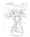
先ず、本発明の第1の実施例について図1乃至図7に基づいて説明する。図1は、本発明を適用する内燃機関の概略構成を示す図である。図1に示す内燃機関1は、4ストローク・サイクルの火花点火式の内燃機関(ガソリンエンジン)である。
先ず、本発明の第1の実施例について図1乃至図7に基づいて説明する。図1は、本発明を適用する内燃機関の概略構成を示す図である。図1に示す内燃機関1は、4ストローク・サイクルの火花点火式の内燃機関(ガソリンエンジン)である。
内燃機関1は、複数の気筒2を有している。ただし、図1においては、複数の気筒2のうち1つの気筒2のみが図示されている。気筒2内には、ピストン3が摺動自在に挿入されている。ピストン3は、コネクティングロッド4を介してクランクシャフト5に連結されている。
内燃機関1は、吸気通路60内の新気(空気)を気筒2内へ導くための吸気ポート6と、気筒2内の既燃ガスを排気通路70へ導くための排気ポート7と、を備えている。吸気ポート6と排気ポート7は、図2に示すように、各ポートの開口端が気筒2の接線方向に向くように形成されたタンジェンシャルポートである。吸気ポート6の開口端と排気ポート7の開口端は、気筒2の周方向において同一方向(図2中の反時計回り)に向くように形成されている。
ここで図1に戻り、内燃機関1は、吸気ポート6の開口端を開閉するための吸気バルブ8と、排気ポート7の開口端を開閉するための排気バルブ9と、を備えている。吸気バルブ8と排気バルブ9は、内燃機関1に回転自在に支持された吸気カム10と排気カム11によりそれぞれ開閉駆動される。吸気カム10と排気カム11は、クランクシャフト5の回転エネルギを利用して回転駆動される。また、内燃機関1には、吸気ポート6内へ向けて燃料を噴射する燃料噴射弁12と、気筒2内に火花を発生させる点火プラグ13が取り付けられている。
内燃機関1は、吸気バルブ8の開弁特性を変更する第1可変動弁機構100と、排気バルブ9の開弁特性を変更する第2可変動弁機構200と、を備えている。第1可変動弁機構100は、少なくとも吸気バルブ8の開閉タイミングを変更可能な機構である。第1可変動弁機構100としては、たとえば、クランクシャフト5に対する吸気カム10の位相を進角又は遅角させる機構を用いることができる。
第2可変動弁機構200は、少なくとも排気バルブ9の作用角とリフト量を変更可能な機構である。第2可変動弁機構200としては、たとえば、リフト量及び作用角が相異する複数の排気カムとそれら複数の排気カムのうち1つの動力を選択的に排気バルブ9に伝達する動力伝達機構と、を備えた機構を用いることができる。また、第2可変動弁機構200としては、排気カム11と排気バルブ9との間に介在し、排気カム11から排気バルブ9へ動力が伝達されるタイミング及び動力伝達量を変更する機構を用いることもできる。
このように構成された内燃機関1には、内燃機関1の運転状態を制御するためのECU14が併設されている。ECU14は、CPU、ROM、RAM、バックアップRAMなどから構成される電子制御ユニットである。
ECU14には、クランクポジションセンサ15やアクセルポジションセンサ16などの各種センサが電気的に接続されている。クランクポジションセンサ15は、クランクシャフト5の回転角度に相関する電気信号を出力するセンサである。アクセルポジションセンサ16は、図示しないアクセルペダルの操作量(アクセル開度)に相関する電気信号を出力するセンサである。
ECU14には、燃料噴射弁12、点火プラグ13、第1可変動弁機構100、及び第2可変動弁機構200などの各種機器が電気的に接続されている。ECU14は、上記した各種センサの出力信号をパラメータとして、上記した各種機器を電気的に制御する。たとえば、ECU14は、クランクポジションセンサ15の出力信号やアクセルポジションセンサ16の出力信号(アクセル開度)に基づいて、燃料噴射弁12や点火プラグ13を制御する。また、ECU14は、本発明の要旨となる成層化処理を実行する。
以下、本実施例における成層化処理の実行方法について説明する。成層化処理では、ECU14は、排気バルブ9の閉弁タイミングが吸気行程の途中まで遅角されるように第2可変動弁機構200を制御するとともに、吸気バルブ8の開弁タイミングが吸気行程における排気バルブ9の閉弁直後まで遅角されるように第1可変動弁機構100を制御する。すなわち、ECU14は、吸気行程の前半は排気バルブ9のみが開き、吸気行程の後半は吸気バルブ8のみが開くように第1可変動弁機構100及び第2可変動弁機構200を制御する。
このように第1可変動弁機構100及び第2可変動弁機構200が制御されると、吸気行程の前半では排気ポート7から気筒2内へ排気が逆流(再流入)する。続いて、吸気行程の後半では、燃料噴射弁12から噴射された燃料を含む新気(空気)が吸気ポート6から気筒2内へ流入する。
吸気行程の前半に気筒2内へ流入した排気は、気筒2の周方向へ旋回するスワール流を形成する。さらに、気筒2内に流入した排気は、ピストン3の下降動作(上死点側から下死点側へ移動する動作)に伴って上死点側から下死点側へ移動する。つまり、吸気行程の前半に気筒2内へ流入した排気は、気筒2内を上死点側から下死点側へ向かって螺旋状に流れる。
吸気行程の後半に気筒2内へ流入した新気は、上記した排気と同様にスワール流を形成する。吸気ポート6と排気ポート7は同一方向のスワール流を形成するように構成されている。さらに、排気は、前述したように気筒2内の下死点寄りの領域へ移動している。そのため、気筒2内に流入した新気の大部分は、排気と干渉することなくスワール流を形成する。その結果、排気の大部分は気筒2内の下死点寄りの領域に集まり、新気の大部分が気筒2内の上死点寄りの領域に集まる。つまり、気筒2内において排気と新気とが成層化される。
上記したように排気と新気の成層化が図れると、燃料を含む新気(混合気)が点火プラグ13の周囲に集まることになる。そのため、気筒2内に存在する排気の量が多い場合であっても、燃料の着火性を高く保つことができる。混合気が着火された後は、排気がEGRガスとして機能するため、窒素酸化物(NOx)の発生量を少なく抑えることができる。
ところで、上記したような成層化処理が実施されると、ピストン3が吸気上死点の近傍に位置する時点の排気バルブ9のリフト量が多くなる可能性がある。そのような場合は、排気バルブ9がピストン3と干渉(バルブスタンプ)する可能性もある。これに対し、ピストン3に設けられるバルブリセスを拡大又は深くする方法が考えられる。この方法によれば、排気バルブ9のバルブスタンプを回避することは可能になるが、機械圧縮比の低下や気流の乱れなどを誘発する可能性がある。その結果、内燃機関1の性能が低下したり、排気エミッションが増加したりする可能性もある。
そこで、本実施例の成層化処理では、ECU14は、成層化処理を実行する場合は成層化処理が実行されない場合に比べ、排気バルブ9のリフト量が少なくなるように第2可変動弁機構200を制御するようにした。なお、ここでいうリフト量は、排気バルブが開弁し始めてから閉弁し終わるまでの期間における最大のリフト量である。
成層化処理が実行される場合の排気バルブ9のリフト量が成層化処理が実行されない場合の排気バルブ9のリフト量より少なくされると、バルブリセスを拡大又は深くするといったピストン3形状の変更を施すことなく、バルブスタンプを回避することができる。その結果、内燃機関1の性能低下や排気エミッションの増加を招くことなく、成層化処理を実行することができる。
また、排気バルブ9のリフト量が少なくされると、排気ポート7から気筒2内へ再流入する際の排気の流速が高められる。そのため、排気は集束性の高いスワール流を形成することができる。その結果、ピストン3の下降動作により発生する吸引力(気筒2内のガスを上死点側から下死点側へ吸引する力)が排気に作用しても、スワール流が減衰又は乱される事態を回避することもできる。
なお、排気バルブ9の閉弁タイミングを吸気行程の途中まで遅角させる方法としては、図3に示すように、作用角を変更せずに開閉タイミングを遅角させる方法が考えられる。図3中の破線は成層化処理が実行されないとき(通常)の開閉タイミングを示し、実線は成層化処理が実行されたときの開閉タイミングを示す。
図3に示した方法により排気バルブ9の閉弁タイミングが遅角された場合は、排気行程中に排気バルブ9が開弁する期間が短くなる。そのような条件下で排気バルブ9のリフト量が通常よりも少なくされると、排気行程中のポンプ損失が増大する。
これに対し、本実施例では、図4に示すように、排気バルブ9の開弁タイミングを略固定しつつ作用角を拡大させることで閉弁タイミングを遅角させるようにした。図4中の破線は通常の開閉タイミングを示し、実線は成層化処理が実行されたときの開閉タイミングを示す。
図4に示した方法により排気バルブ9の開閉タイミングが遅角されると、排気行程中に排気バルブ9が開弁する期間は通常と略同等になる。そのため、排気バルブ9のリフト量が少なくされてもポンプ損失の増加を少なく抑えることができる。
なお、図4に示した方法によると、吸気行程中に気筒2内へ再吸入される排気が少なくなる可能性がある。ただし、排気行程中の排気バルブ9のリフト量が通常より少なくなるため、排気行程中に気筒2内から排気ポート7へ排出される既燃ガスの量が通常より少なくなる。言い換えれば、排気行程が終了する時点(吸気上死点)において気筒2内に残留する既燃ガス(残留既燃ガス)の量は、通常より多くなる。残留既燃ガスは、吸気行程中に再流入される排気と同等の性状を有する。そのため、吸気行程中に気筒2内へ再流入する排気が減少しても、その減少分は残留既燃ガスの増加分によって補われることになる。
従って、本実施例の内燃機関の吸排気システムによれば、内燃機関1の性能低下や排気エミッションの低下を回避しつつ、気筒2内において排気と新気の成層化を図ることができる。
本実施例では、新気と排気が同一方向のスワール流を形成するように吸気ポート6及び排気ポート7を構成する例について述べたが、スワール流の方向に加えスワール比も略同等になるように構成されてもよい。気筒2内に新気が流入する時点で新気のスワール比と排気のスワール比との差が大きくなると、新気の層と排気の層との境界部分において両者が混合する可能性がある。よって、気筒2内に新気が流入する時点で新気のスワール比と排気のスワール比が略同等であれば、前記した境界部分において新気と排気との混合を抑制することができる。
なお、成層化処理実行時における排気バルブ9の閉弁タイミング及び吸気バルブ8の開弁タイミングは、目標吸入空気量によって変更される場合がある。排気バルブ9の閉弁タイミング及び吸気バルブ8の開弁タイミングが変更されると、新気のスワール比と排気のスワール比との相対関係も変化する可能性がある。
そこで、吸気バルブ8のリフト量を変更することにより、排気のスワール比と新気のスワール比との差が許容範囲内に収まるようにしてもよい。たとえば、排気バルブ9の閉弁タイミング及び吸気バルブ8の開弁タイミングが遅い場合は早い場合に比べ、排気のスワール比が低くなるとともに吸気のスワール比が高くなると考えられる。そのため、排気バルブ9の閉弁タイミング及び吸気バルブ8の開弁タイミングが遅い場合は早い場合に比べ、吸気バルブ8のリフト量を多くしてもよい。
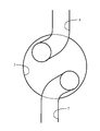
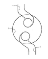
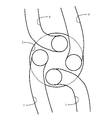
また、本実施例では、吸気ポート6及び排気ポート7がタンジェンシャルポートである例について述べたが、図5に示すようなヘリカルポートであってもよい。さらに、吸気ポート6及び排気ポート7の個数は1つに限られるものではなく、吸気ポート6及び排気ポート7がそれぞれ複数設けられてもよい。たとえば、図6に示すように、吸気ポート6及び排気ポート7がそれぞれ2つ設けられ、それらのポートがタンジェンシャルポートで構成されてもよい。また、図7に示すように、吸気ポート6及び排気ポート7がそれぞれ2つ設けられ、それらのポートがヘリカルポートで構成されてもよい。
要するに、吸気ポート6から気筒2内へ流入する新気と排気ポート7から気筒2内へ再流入する排気とが互いに同一方向のスワール流を形成することができる限り、ポートの形状や個数は如何なる形状及び個数であってもよい。
<実施例2>
次に、本発明の第2の実施例について図8に基づいて説明する。ここでは、前述した第1の実施例と異なる構成について説明し、同様の構成については説明を省略する。
次に、本発明の第2の実施例について図8に基づいて説明する。ここでは、前述した第1の実施例と異なる構成について説明し、同様の構成については説明を省略する。
前述した第1の実施例と本実施例との相違点は、内燃機関の吸気通路に過給機が設けられている点にある。図8は、本実施例における内燃機関の概略構成を示す図である。図8において、前述した第1の実施例(図1を参照)と同様の構成要素には、同一の符号が付されている。
図8において、内燃機関1の吸気通路60には、該吸気通路60を流れる新気を圧縮する過給機17が設けられている。過給機17は、過給圧を変更可能な過給機である。過給圧を変更可能な過給機としては、過給機を迂回するガス量を調整可能な機械式圧縮比、コンプレッサとタービンを備えたターボチャージャであってタービンを迂回する排気量を調整可能なターボチャージャ、又はコンプレッサとタービンを備えたターボチャージャであってタービンの容量を調整可能な可変容量型ターボチャージャなどを用いることができる。
過給圧を変更可能な過給機17を備えた内燃機関1において成層化処理が実行される場合は、ECU14は、成層化処理が実行されない場合に比べ、過給圧が高くなるように前記過給機17を制御する。成層化処理が実行されると、吸気バルブ8が開弁する前に気筒2内に既に排気が吸入されている。そのため、吸気バルブ8が開弁したときの筒内圧は、排気が吸入されていない場合より高くなる(筒内負圧が小さくなる)。よって、気筒2内に吸入される新気の量が過少となったり、気筒2内の排気や残留既燃ガスが吸気ポート6へ逆流したりする可能性がある。
気筒2内に吸入される空気量が少なくなると、内燃機関1の出力が低下する。また、気筒2内の排気や残留既燃ガスが吸気ポート6へ逆流すると、逆流したガスが新気と混合しながら気筒2内へ流入するため、新気と排気の成層化を図ることが困難となる。
これに対し、成層化処理が実行されないときに比して成層化処理が実行されたときの過給圧が高くされると、吸気バルブ8が開弁したときに気筒2内の排気や残留既燃ガスが吸気ポート6へ逆流する事態や、気筒2内に吸入される空気量が過少となる事態を回避することができる。その結果、内燃機関1の出力低下を抑制しつつ、新気と排気の成層化を図ることが可能となる。
前述した第1及び第2の実施例では、本発明を適用する内燃機関として火花点火式の内燃機関(ガソリンエンジン)を例に挙げたが、圧縮着火式の内燃機関(ディーゼルエンジン)に本発明を適用することも可能である。
1 内燃機関
2 気筒
3 ピストン
4 コネクティングロッド
5 クランクシャフト
6 吸気ポート
7 排気ポート
8 吸気バルブ
9 排気バルブ
10 吸気カム
11 排気カム
12 燃料噴射弁
13 点火プラグ
14 ECU
15 クランクポジションセンサ
16 アクセルポジションセンサ
17 過給機
60 吸気通路
70 排気通路
100 第1可変動弁機構
200 第2可変動弁機構
2 気筒
3 ピストン
4 コネクティングロッド
5 クランクシャフト
6 吸気ポート
7 排気ポート
8 吸気バルブ
9 排気バルブ
10 吸気カム
11 排気カム
12 燃料噴射弁
13 点火プラグ
14 ECU
15 クランクポジションセンサ
16 アクセルポジションセンサ
17 過給機
60 吸気通路
70 排気通路
100 第1可変動弁機構
200 第2可変動弁機構
Claims (5)
- 吸気バルブ及び排気バルブの開弁特性を変更する可変動弁機構と、
吸気行程の開始から吸気行程の途中まで排気バルブのみが開弁し、吸気行程の途中から吸気バルブのみが開弁するように前記可変動弁機構を制御することにより、気筒内において排気と新気を成層化させる第1制御部と、
前記第1制御部により排気と新気が成層化されるときは、前記第1制御部により排気と新気が成層化されないときに比べ、前記排気バルブのリフト量が少なくなるように前記可変動弁機構を制御する第2制御部と、
を備える内燃機関の吸排気システム。 - 請求項1において、前記可変動弁機構は、前記排気バルブの作用角を変更可能な機構を含み、
前記第1制御部は、気筒内において排気と新気を成層化させるときは、前記排気バルブが排気行程から吸気行程の途中まで連続して開弁するように前記可変動弁機構を制御する内燃機関の吸排気システム。 - 請求項2において、前記吸気弁により開閉される吸気ポートと前記排気バルブにより開閉される排気ポートは、前記排気ポートから気筒内へ再流入する排気と前記吸気ポートから気筒内へ流入する新気とが互いに同一方向のスワール流を発生するように構成される内燃機関の吸排気システム。
- 請求項3において、前記吸気ポート及び前記排気ポートは、前記第1制御部により排気と新気が成層化されるときに、排気のスワール比と新気のスワール比が同等となるように構成される内燃機関の吸排気システム。
- 請求項3又は4において、内燃機関に対して吸気を過給する過給機をさらに備え、
前記第2制御部は、前記第1制御部により排気と新気が成層化されるときは、前記第1制御部により排気と新気が成層化されないときに比べ、前記過給機の過給圧を高める内燃機関の吸排気システム。
Priority Applications (1)
| Application Number | Priority Date | Filing Date | Title |
|---|---|---|---|
| PCT/JP2010/056704 WO2011128997A1 (ja) | 2010-04-14 | 2010-04-14 | 内燃機関の吸排気システム |
Applications Claiming Priority (1)
| Application Number | Priority Date | Filing Date | Title |
|---|---|---|---|
| PCT/JP2010/056704 WO2011128997A1 (ja) | 2010-04-14 | 2010-04-14 | 内燃機関の吸排気システム |
Publications (1)
| Publication Number | Publication Date |
|---|---|
| WO2011128997A1 true WO2011128997A1 (ja) | 2011-10-20 |
Family
ID=44798390
Family Applications (1)
| Application Number | Title | Priority Date | Filing Date |
|---|---|---|---|
| PCT/JP2010/056704 Ceased WO2011128997A1 (ja) | 2010-04-14 | 2010-04-14 | 内燃機関の吸排気システム |
Country Status (1)
| Country | Link |
|---|---|
| WO (1) | WO2011128997A1 (ja) |
Citations (4)
| Publication number | Priority date | Publication date | Assignee | Title |
|---|---|---|---|---|
| JP2002276395A (ja) * | 2001-03-23 | 2002-09-25 | Nissan Motor Co Ltd | 内燃機関の吸気装置 |
| JP2005325818A (ja) * | 2004-05-17 | 2005-11-24 | Koichi Hatamura | エンジンの運転制御装置 |
| JP2008002404A (ja) * | 2006-06-23 | 2008-01-10 | Toyota Motor Corp | 電磁駆動弁の制御装置 |
| JP4201395B2 (ja) * | 1998-08-04 | 2008-12-24 | 日産自動車株式会社 | 内燃機関の燃焼制御装置 |
-
2010
- 2010-04-14 WO PCT/JP2010/056704 patent/WO2011128997A1/ja not_active Ceased
Patent Citations (4)
| Publication number | Priority date | Publication date | Assignee | Title |
|---|---|---|---|---|
| JP4201395B2 (ja) * | 1998-08-04 | 2008-12-24 | 日産自動車株式会社 | 内燃機関の燃焼制御装置 |
| JP2002276395A (ja) * | 2001-03-23 | 2002-09-25 | Nissan Motor Co Ltd | 内燃機関の吸気装置 |
| JP2005325818A (ja) * | 2004-05-17 | 2005-11-24 | Koichi Hatamura | エンジンの運転制御装置 |
| JP2008002404A (ja) * | 2006-06-23 | 2008-01-10 | Toyota Motor Corp | 電磁駆動弁の制御装置 |
Similar Documents
| Publication | Publication Date | Title |
|---|---|---|
| US10794317B2 (en) | Control device for compression-ignition engine | |
| CN110513207B (zh) | 压缩着火式发动机的控制装置 | |
| JP5278600B2 (ja) | 内燃機関の燃焼制御装置 | |
| US20090187329A1 (en) | Method of Controlling a Mechanical Compression Ratio and a Start Timing of an Actual Compression Action | |
| EP3015692B1 (en) | Engine control device | |
| JP5834829B2 (ja) | 火花点火式ガソリンエンジンの制御装置 | |
| JP5589959B2 (ja) | 過給機付き火花点火式エンジン | |
| CN101861452B (zh) | 高膨胀比内燃机 | |
| CN103052783A (zh) | 内燃机及相应的运行方法 | |
| JP2008025534A (ja) | 予混合圧縮自着火内燃機関 | |
| JP5428473B2 (ja) | 内燃機関を制御する方法及び装置 | |
| US10982616B2 (en) | Premixed compression ignition type engine with supercharging system | |
| CN107524536A (zh) | 内燃机及内燃机的控制方法 | |
| WO2014208137A1 (ja) | エンジンの制御装置 | |
| JP6131840B2 (ja) | 圧縮着火式エンジンの制御装置 | |
| JP2020122448A (ja) | 圧縮着火式エンジンの制御装置 | |
| JP7379857B2 (ja) | エンジンの制御装置および制御方法 | |
| JP2008025445A (ja) | 内燃機関の制御装置 | |
| JP2005002967A (ja) | ターボ過給機付火花点火式直噴エンジンの制御装置 | |
| WO2011128997A1 (ja) | 内燃機関の吸排気システム | |
| JP2013124623A (ja) | 可変圧縮比機構を備える内燃機関 | |
| JP2018168719A (ja) | 内燃機関 | |
| CN100507249C (zh) | 发动机 | |
| JP2008051017A (ja) | 予混合圧縮自着火内燃機関 | |
| JPH06330776A (ja) | 機械式過給機付エンジンの吸気装置 |
Legal Events
| Date | Code | Title | Description |
|---|---|---|---|
| 121 | Ep: the epo has been informed by wipo that ep was designated in this application |
Ref document number: 10849834 Country of ref document: EP Kind code of ref document: A1 |
|
| NENP | Non-entry into the national phase |
Ref country code: DE |
|
| 122 | Ep: pct application non-entry in european phase |
Ref document number: 10849834 Country of ref document: EP Kind code of ref document: A1 |
|
| NENP | Non-entry into the national phase |
Ref country code: JP |