WO2011125599A1 - 濾過装置及び水処理装置 - Google Patents
濾過装置及び水処理装置 Download PDFInfo
- Publication number
- WO2011125599A1 WO2011125599A1 PCT/JP2011/057584 JP2011057584W WO2011125599A1 WO 2011125599 A1 WO2011125599 A1 WO 2011125599A1 JP 2011057584 W JP2011057584 W JP 2011057584W WO 2011125599 A1 WO2011125599 A1 WO 2011125599A1
- Authority
- WO
- WIPO (PCT)
- Prior art keywords
- water
- treated
- filtration
- turbidity
- sheet
- Prior art date
- Legal status (The legal status is an assumption and is not a legal conclusion. Google has not performed a legal analysis and makes no representation as to the accuracy of the status listed.)
- Ceased
Links
Images








Classifications
-
- C—CHEMISTRY; METALLURGY
- C02—TREATMENT OF WATER, WASTE WATER, SEWAGE, OR SLUDGE
- C02F—TREATMENT OF WATER, WASTE WATER, SEWAGE, OR SLUDGE
- C02F1/00—Treatment of water, waste water, or sewage
- C02F1/001—Processes for the treatment of water whereby the filtration technique is of importance
-
- B—PERFORMING OPERATIONS; TRANSPORTING
- B01—PHYSICAL OR CHEMICAL PROCESSES OR APPARATUS IN GENERAL
- B01D—SEPARATION
- B01D25/00—Filters formed by clamping together several filtering elements or parts of such elements
- B01D25/22—Cell-type filters
- B01D25/24—Cell-type roll filters
-
- B—PERFORMING OPERATIONS; TRANSPORTING
- B01—PHYSICAL OR CHEMICAL PROCESSES OR APPARATUS IN GENERAL
- B01D—SEPARATION
- B01D61/00—Processes of separation using semi-permeable membranes, e.g. dialysis, osmosis or ultrafiltration; Apparatus, accessories or auxiliary operations specially adapted therefor
- B01D61/02—Reverse osmosis; Hyperfiltration ; Nanofiltration
- B01D61/025—Reverse osmosis; Hyperfiltration
-
- B—PERFORMING OPERATIONS; TRANSPORTING
- B01—PHYSICAL OR CHEMICAL PROCESSES OR APPARATUS IN GENERAL
- B01D—SEPARATION
- B01D61/00—Processes of separation using semi-permeable membranes, e.g. dialysis, osmosis or ultrafiltration; Apparatus, accessories or auxiliary operations specially adapted therefor
- B01D61/02—Reverse osmosis; Hyperfiltration ; Nanofiltration
- B01D61/04—Feed pretreatment
-
- B—PERFORMING OPERATIONS; TRANSPORTING
- B01—PHYSICAL OR CHEMICAL PROCESSES OR APPARATUS IN GENERAL
- B01D—SEPARATION
- B01D61/00—Processes of separation using semi-permeable membranes, e.g. dialysis, osmosis or ultrafiltration; Apparatus, accessories or auxiliary operations specially adapted therefor
- B01D61/02—Reverse osmosis; Hyperfiltration ; Nanofiltration
- B01D61/08—Apparatus therefor
-
- B—PERFORMING OPERATIONS; TRANSPORTING
- B01—PHYSICAL OR CHEMICAL PROCESSES OR APPARATUS IN GENERAL
- B01D—SEPARATION
- B01D63/00—Apparatus in general for separation processes using semi-permeable membranes
- B01D63/10—Spiral-wound membrane modules
-
- B—PERFORMING OPERATIONS; TRANSPORTING
- B01—PHYSICAL OR CHEMICAL PROCESSES OR APPARATUS IN GENERAL
- B01D—SEPARATION
- B01D65/00—Accessories or auxiliary operations, in general, for separation processes or apparatus using semi-permeable membranes
- B01D65/02—Membrane cleaning or sterilisation ; Membrane regeneration
-
- B—PERFORMING OPERATIONS; TRANSPORTING
- B01—PHYSICAL OR CHEMICAL PROCESSES OR APPARATUS IN GENERAL
- B01D—SEPARATION
- B01D2311/00—Details relating to membrane separation process operations and control
- B01D2311/04—Specific process operations in the feed stream; Feed pretreatment
-
- B—PERFORMING OPERATIONS; TRANSPORTING
- B01—PHYSICAL OR CHEMICAL PROCESSES OR APPARATUS IN GENERAL
- B01D—SEPARATION
- B01D2311/00—Details relating to membrane separation process operations and control
- B01D2311/06—Specific process operations in the permeate stream
-
- B—PERFORMING OPERATIONS; TRANSPORTING
- B01—PHYSICAL OR CHEMICAL PROCESSES OR APPARATUS IN GENERAL
- B01D—SEPARATION
- B01D2313/00—Details relating to membrane modules or apparatus
- B01D2313/14—Specific spacers
- B01D2313/143—Specific spacers on the feed side
-
- B—PERFORMING OPERATIONS; TRANSPORTING
- B01—PHYSICAL OR CHEMICAL PROCESSES OR APPARATUS IN GENERAL
- B01D—SEPARATION
- B01D2313/00—Details relating to membrane modules or apparatus
- B01D2313/40—Adsorbents within the flow path
-
- B—PERFORMING OPERATIONS; TRANSPORTING
- B01—PHYSICAL OR CHEMICAL PROCESSES OR APPARATUS IN GENERAL
- B01D—SEPARATION
- B01D2313/00—Details relating to membrane modules or apparatus
- B01D2313/90—Additional auxiliary systems integrated with the module or apparatus
- B01D2313/902—Integrated cleaning device
-
- B—PERFORMING OPERATIONS; TRANSPORTING
- B01—PHYSICAL OR CHEMICAL PROCESSES OR APPARATUS IN GENERAL
- B01D—SEPARATION
- B01D2313/00—Details relating to membrane modules or apparatus
- B01D2313/90—Additional auxiliary systems integrated with the module or apparatus
- B01D2313/903—Integrated control or detection device
-
- B—PERFORMING OPERATIONS; TRANSPORTING
- B01—PHYSICAL OR CHEMICAL PROCESSES OR APPARATUS IN GENERAL
- B01D—SEPARATION
- B01D2321/00—Details relating to membrane cleaning, regeneration, sterilization or to the prevention of fouling
- B01D2321/04—Backflushing
-
- C—CHEMISTRY; METALLURGY
- C02—TREATMENT OF WATER, WASTE WATER, SEWAGE, OR SLUDGE
- C02F—TREATMENT OF WATER, WASTE WATER, SEWAGE, OR SLUDGE
- C02F1/00—Treatment of water, waste water, or sewage
- C02F1/28—Treatment of water, waste water, or sewage by sorption
- C02F1/283—Treatment of water, waste water, or sewage by sorption using coal, charred products, or inorganic mixtures containing them
-
- C—CHEMISTRY; METALLURGY
- C02—TREATMENT OF WATER, WASTE WATER, SEWAGE, OR SLUDGE
- C02F—TREATMENT OF WATER, WASTE WATER, SEWAGE, OR SLUDGE
- C02F1/00—Treatment of water, waste water, or sewage
- C02F1/44—Treatment of water, waste water, or sewage by dialysis, osmosis or reverse osmosis
- C02F1/441—Treatment of water, waste water, or sewage by dialysis, osmosis or reverse osmosis by reverse osmosis
-
- C—CHEMISTRY; METALLURGY
- C02—TREATMENT OF WATER, WASTE WATER, SEWAGE, OR SLUDGE
- C02F—TREATMENT OF WATER, WASTE WATER, SEWAGE, OR SLUDGE
- C02F1/00—Treatment of water, waste water, or sewage
- C02F1/52—Treatment of water, waste water, or sewage by flocculation or precipitation of suspended impurities
-
- C—CHEMISTRY; METALLURGY
- C02—TREATMENT OF WATER, WASTE WATER, SEWAGE, OR SLUDGE
- C02F—TREATMENT OF WATER, WASTE WATER, SEWAGE, OR SLUDGE
- C02F1/00—Treatment of water, waste water, or sewage
- C02F1/52—Treatment of water, waste water, or sewage by flocculation or precipitation of suspended impurities
- C02F1/5209—Regulation methods for flocculation or precipitation
-
- C—CHEMISTRY; METALLURGY
- C02—TREATMENT OF WATER, WASTE WATER, SEWAGE, OR SLUDGE
- C02F—TREATMENT OF WATER, WASTE WATER, SEWAGE, OR SLUDGE
- C02F2201/00—Apparatus for treatment of water, waste water or sewage
- C02F2201/002—Construction details of the apparatus
- C02F2201/003—Coaxial constructions, e.g. a cartridge located coaxially within another
-
- C—CHEMISTRY; METALLURGY
- C02—TREATMENT OF WATER, WASTE WATER, SEWAGE, OR SLUDGE
- C02F—TREATMENT OF WATER, WASTE WATER, SEWAGE, OR SLUDGE
- C02F2301/00—General aspects of water treatment
- C02F2301/08—Multistage treatments, e.g. repetition of the same process step under different conditions
-
- C—CHEMISTRY; METALLURGY
- C02—TREATMENT OF WATER, WASTE WATER, SEWAGE, OR SLUDGE
- C02F—TREATMENT OF WATER, WASTE WATER, SEWAGE, OR SLUDGE
- C02F2303/00—Specific treatment goals
- C02F2303/16—Regeneration of sorbents, filters
-
- C—CHEMISTRY; METALLURGY
- C02—TREATMENT OF WATER, WASTE WATER, SEWAGE, OR SLUDGE
- C02F—TREATMENT OF WATER, WASTE WATER, SEWAGE, OR SLUDGE
- C02F2303/00—Specific treatment goals
- C02F2303/20—Prevention of biofouling
Definitions
- the present invention relates to a filtration device for treating water to be treated containing suspended substances such as industrial water, city water, well water, river water, lake water, and factory waste water, and a water treatment device using the same, particularly reverse osmosis.
- the present invention relates to a filtration device that can be suitably used in a preceding stage such as a membrane device.
- an inorganic flocculant and an anionic polymer flocculant are added to the treated water.
- sand filtration and pressure levitation processing have a problem that the apparatus becomes large.
- removal of a turbidity may become inadequate.
- an ultrafiltration membrane (UF) device or a microfiltration membrane (MF) device has been spreading as a filtration device.
- the ultrafiltration membrane device and the microfiltration membrane device have a problem that clogging occurs due to suspended substances, inorganic substances, and organic substances, and a problem that the cost of the membrane is high.
- an object of the present invention is to provide an inexpensive filtration device that can provide clear treated water that can be supplied to a reverse osmosis membrane device and the like, and that is difficult to block, and a water treatment device using the same.
- the present inventors have obtained a sheet-like mesh sheet having pores through which the water to be treated passes as a filter body for capturing turbidity, and to be treated as compared with the mesh sheet. Filtration with a structure in which the water to be treated passes through the mesh sheet vertically, using a spirally wound sheet-like member in which the sheet surfaces of sheet-like spacers that are difficult for water to pass through are overlapped.
- the present invention has been completed by finding that the above object can be achieved by using the apparatus.
- the filtration device of the present invention is configured such that the filter body having the sheet-like member wound in a spiral shape and the water to be treated are passed, and the filter core body has an axial core along the direction of water passage.
- the body body has a filtration tank filled therein, and the sheet-like member has a sheet-like mesh sheet having holes through which the water to be treated passes, and the water to be treated is less likely to pass than the mesh sheet.
- the sheet surfaces of the sheet-like spacer are overlapped with each other.
- the said filter body is a thing by which the said sheet-like member was wound around the core material in the shape of a spiral.
- the spacer may be a nonwoven fabric formed of fibers having a diameter of 0.1 to 100 ⁇ m.
- the spacer may be formed of activated carbon fibers having a diameter of 0.1 to 100 ⁇ m.
- the spacer is composed of a non-woven fabric formed of fibers having a diameter of 0.1 to 100 ⁇ m and a water-impermeable sheet that does not transmit the water to be treated.
- the mesh sheet is preferably formed of fibers having a diameter of 0.1 to 0.6 mm.
- Another aspect of the present invention resides in a water treatment device having a reverse osmosis membrane device in the subsequent stage of the filtration device.
- the filtration unit has a porosity of 50 to 95% at the time of passing the coarse filter body, which has a string-like turbidity trapping part in front of the filtration device and traps the turbidity in the water to be treated. It is preferable to have a coarse filtration device filled in the coarse filtration tank so that
- the coarse filtration device and the filtration device may be accommodated in a single container, and the coarse filtration device and the filtration device may be integrated.
- a reaction tank into which the water to be treated is introduced before the filtration device and a flocculant introduction means for introducing the flocculant into the reaction tank or the front stage of the reaction tank and adding the flocculant to the water to be treated. It is preferable to have an aggregating treatment means comprising
- a cleaning liquid introducing means for introducing the cleaning liquid or a mixed liquid of the cleaning liquid and air at an arbitrary frequency from the opposite direction to the processing.
- the sheet-like member has a sheet-like mesh sheet having pores through which the water to be treated passes, and the sheet surfaces of the sheet-like spacer in which the water to be treated is difficult to pass compared to the mesh sheet.
- the water to be treated can be suitably treated for a long period of time by providing this filtration device in the previous stage of the reverse osmosis membrane device or the like.
- this filtration apparatus can be made into the water treatment apparatus which has a coagulation process means in the front
- a membrane separation treatment means such as a filtration device or a reverse osmosis membrane device provided in the subsequent stage.
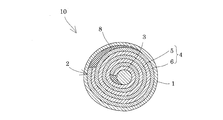
- FIG. 3 is a perspective view showing a filter body according to Embodiment 1.
- FIG. 3 is an enlarged view of a main part of a mesh sheet according to Embodiment 1.
- FIG. It is a schematic system diagram of an example of a water treatment device according to the second embodiment. It is a figure which shows the structure of the example of a water treatment apparatus which concerns on Embodiment 2.
- FIG. It is a schematic system diagram of an example of a water treatment device according to the second embodiment. It is a schematic system diagram of an example of a water treatment device according to the second embodiment.
- FIG. 1 It is a schematic system diagram of an example of a water treatment device according to the second embodiment. It is sectional drawing which shows the structure of the example of the water treatment apparatus which concerns on Embodiment 3.
- FIG. It is sectional drawing which shows the structure of the coarse filtration apparatus which concerns on Embodiment 3. It is a principal part enlarged view of the coarse filtration apparatus which concerns on Embodiment 3.
- FIG. It is a figure which shows an example of the turbidity capture
- FIG. It is a figure which shows the measuring method of the differential pressure
- FIG. 1 is a longitudinal sectional view in the direction of water flow of water to be treated showing the configuration of a filtration apparatus according to Embodiment 1 of the present invention
- FIG. 2 is a transverse sectional view
- FIG. 3 is a filtration of the filtration apparatus. It is a perspective view which shows a body.
- the filtration apparatus 10 has the cylindrical filtration tank 1 in which to-be-processed water is passed, and the filter body 2 which captures the turbidity in the to-be-processed water passed.
- the filter body 2 includes a core body 3 connected to both ends of the filtration tank 1 in the water flow direction, and a filter body main body 4 including a sheet-like member wound around the core material 3 in a spiral shape.
- This sheet member has a sheet-like mesh sheet 5 having pores through which the water to be treated passes, and a sheet surface of a sheet-like spacer 6 in which the water to be treated is difficult to pass compared to the mesh sheet 5. It is.
- a circular plate 7 made of resin or the like provided with a plurality of holes to the extent that water to be treated containing turbidity (suspension material) or the like can freely pass is provided at both ends of the filtration tank 1 in the water flow direction.
- the both ends of the core material 3 are fixed to the center of each plate 7.
- the filter body 2 is filled into the filtration tank 1 whole inside so that the axial center of the filter body main body 4 may follow the water flow direction of to-be-processed water.
- the gap between the inner wall of the filtration tank 1 and the outer periphery of the filter body 4 and the gap near the core 3 are filled with a water-impermeable member 8 through which the water to be treated such as an adhesive does not pass. Cannot pass through.
- the shaft core of the filter body 4 is the center of the spiral of the filter body 4 wound in a spiral shape, and the core material 3 corresponds to this embodiment.
- the spacer 6 is less likely to pass the water to be treated than the mesh sheet 5, so that most of the water to be treated passes through the pores of the mesh sheet 5.
- 5 passes through the mesh sheet 5 in the plane direction, and the turbidity contained in the treated water is trapped in the mesh sheet 5 and the treated water from which the turbidity has been removed is discharged from the filtration tank 1.
- the water to be treated is passed through the mesh sheet 5 having pores through which the water to be treated passes and capable of trapping turbidity, not vertically across the thickness direction, but longitudinally.
- the filtration device 10 can be used in the front stage of a reverse osmosis membrane (RO) device instead of a membrane separation device such as an ultrafiltration membrane (UF) device or a microfiltration membrane (MF) device. Blockage of the device can be suppressed.
- the filtration device 10 is not filtered using a membrane as in the case of an ultrafiltration membrane device or a microfiltration membrane device, so it is difficult to block and is inexpensive.
- the mesh sheet 5 is not particularly limited as long as the mesh sheet 5 has pores through which the water to be treated can pass and can remove the turbidity contained in the water to be treated to a desired extent.
- FIG. 4 Such a woven fabric formed of warp yarns 9a and weft yarns 9b. 4 is an enlarged plan view of the main part of the mesh sheet 5 (FIG. 4A) and a cross-sectional view taken along the line AA ′ of FIG. 4A (FIG. 4B).
- the distance between adjacent warp yarns 9a and adjacent weft yarns 9b of the mesh sheet 5, that is, the opening (indicated by OP in FIG. 4) is preferably about 200 to 4000 ⁇ m. ), That is, the space ratio (opening area) in a plan view of the mesh sheet 5 is preferably about 40 to 90%, and the height of the intersection (thickness indicated by T in the figure) Is preferably 500 to 1200 ⁇ m. As specific products, for example, about 100 to 8 items (NBC) may be used. If it is this range, a turbidity can be removed especially suitably.
- a mesh sheet having an intersection portion height of usually about 0.65 to 1.2 mm is used as a raw water flow path spacer. Therefore, when the reverse osmosis membrane device is used as a filtration device used in the previous stage of the reverse osmosis membrane device, that is, as a filtration device for supplying treated water to the reverse osmosis membrane device to prevent the reverse osmosis membrane device from being blocked, it is more intersecting than the reverse osmosis membrane device. This is because it is preferable to use a mesh sheet having a low height.
- the diameter D of the fibers that become the warp yarn 9a and the weft yarn 9b is preferably 0.1 to 0.6 mm, more preferably about 0.1 to 0.4 mm.
- the diameter D of the fibers that become the warp yarn 9a and the weft yarn 9b is preferably 0.1 to 0.6 mm, more preferably about 0.1 to 0.4 mm.
- Examples of the material such as the yarn constituting the mesh sheet 5 include synthetic resins such as polyolefin, polyester, nylon, and polyvinylidene fluoride (PVDF), and metal fibers. From the viewpoint of chemical resistance and economy. Polyolefins are preferred. In addition, although the woven fabric was illustrated in FIG. 4, the nonwoven fabric which has a comparatively big hole formed with the fiber may be sufficient.
- the spacer 6 is not particularly limited as long as the water to be treated is less likely to pass through than the mesh sheet 5.
- it may be a non-woven fabric formed of fibers having a diameter of 0.1 to 100 ⁇ m, preferably about 0.5 to 30 ⁇ m, or may be laminated by sticking them together or integrally forming them by heat fusion.
- the spacer 6 since the to-be-processed water can be made to contact the mesh sheet
- a nonwoven fabric is used as the spacer 6, since the turbidity of to-be-processed water can be capture
- Examples of the material of the spacer 6 include polyolefin, polyester, nylon, polyvinylidene fluoride (PVDF), metal fiber, activated carbon fiber, and the like.
- Polyolefins are preferred from the viewpoint of chemical resistance and economy.
- activated carbon fibers are preferred from the viewpoint that reduction treatment of NaClO or the like contained in the water to be treated can be performed and an apparatus such as an activated carbon tower can be dispensed with.
- the form in which the mesh sheet 5 and the spacer 6 are superposed is not particularly limited, and the sheet surfaces may be bonded together or integrally formed by heat fusion.
- size of the mesh sheet 5 and the spacer 6 does not need to be the same, in order to process a to-be-processed water uniformly, it is preferable that it is substantially the same.
- the length of the mesh sheet or the spacer 6 in the water passing direction depends on the turbidity of the water to be treated, the amount to be treated and the turbidity of the treated water to be obtained, but may be about 200 to 1000 mm, for example.
- the material of the core material 3 around which the sheet member on which the mesh sheet 5 and the spacer 6 are superimposed is wound is not particularly limited, and plastic, metal, or the like can be used, but from the economical viewpoint, vinyl chloride piping (CVP piping) ) Is preferable.
- the shape 3 of the core material is not particularly limited, and may be, for example, a cylindrical shape or a prismatic shape.
- the method for winding the sheet member around the core member 3 is not particularly limited. For example, the end of the sheet member is fixed to the core member 3 with an adhesive or the like, and the sheet member is wound around the core member 3. It is sufficient to wind the film to have an arbitrary diameter according to the amount of water to be treated and the turbidity.
- the filter tank 1 is not limited.
- the material can be made of stainless steel or fiber reinforced plastic (FRP), and if the size is a hollow cylindrical shape (tubular shape), the diameter is 100 to 1000 mm.
- the height can be 200 to 1000 mm.
- the cylindrical filtration tank 1 in FIG. 1 it does not need to be a cylinder and may be the shape which can permeate
- treated water industrial water, city water, well water, river water, lake water, factory waste water (particularly biological treated water obtained by biological treatment of waste water from the factory), and flocculant added to these Examples include water subjected to agglomeration treatment.
- the filter body 2 having the filter body 4 wound around the core 3 is used as the filter body 2, but the number of windings is not limited, the amount of water to be treated, the turbidity, etc. May be adjusted as appropriate. Accordingly, the filter body 2 may be formed by winding the filter body 4 only once. However, the larger the number of windings, the easier the shape of the mesh sheet 5 is retained by the spacer 6, and the water to be treated is uniformly distributed. 5 can be cut longitudinally, and the water treatment is stable, which is preferable.
- a filter body 2 in which a filter body main body 4 is wound around a core material 3 is used as the filter body 2, but the core material 3 may be omitted.
- the mesh sheet 5 may be passed with a spacer 6 or the like. If the shape at the time of water is hold
- FIG. 1 although it was set as the filtration apparatus 10 which filled the filter body 2 in the hollow cylindrical filter tank 1, it joined so that to-be-processed water might leak by winding sheets, such as FRP, around the filter body 2 It is good also as what you did.
- the spacer 6 may be made of a water-impermeable material so that the water to be treated does not leak, so that the spacer 6 also serves as the filtration tank 1.
- FIG. 5 is a schematic system diagram of a water treatment device according to Embodiment 2 of the present invention.
- symbol is attached
- the water treatment device 30 is provided with a reverse osmosis membrane device 31 that performs membrane separation treatment of water to be treated with a reverse osmosis membrane on the downstream side (downstream side) of the filtration device 10 of the first embodiment. is there.
- water to be treated (raw water) is introduced into the filtration device 10.
- transduced into the filtration apparatus 10 cuts the mesh sheet
- emitted from the filtration apparatus 10 is supplied to the reverse osmosis membrane apparatus 31 of a back
- emitted from the filtration apparatus 10 is clarified.
- the reverse osmosis membrane device 31 can be used in the preceding stage of the reverse osmosis membrane device 31 instead of a membrane separation device such as an ultrafiltration membrane device or a microfiltration membrane device. Further, unlike the UF device or the MF device, since it is not filtration using a membrane, it is difficult to block and is inexpensive.
- the reverse osmosis membrane device 31 provided in the subsequent stage of the filtration device 10 has a cross-sectional area of the water passage of the treated water larger than that of the mesh sheet 5 in the direction of water passage of the treated water. What has the width
- the form of the reverse osmosis membrane device 31 is not particularly limited, but for example, a so-called spiral type of a shape in which a reverse osmosis membrane bound in a bag is wound around a hollow core member having a water passage hole on its side is increased in size. Since it is easy to respond to, it is preferable.
- a spiral type reverse osmosis membrane device having the same diameter as the filtration device 10 is preferable.
- the spiral type reverse osmosis membrane device 31 the treated water whose impurities have been separated by the reverse osmosis membrane is discharged from the hollow core material, and the membrane separation treatment is performed by the reverse osmosis membrane from other than the core material. So-called concentrated water containing a large amount of impurities is discharged.
- membrane separation processing means such as a microfiltration membrane (MF membrane), an ultrafiltration membrane (UF membrane), and a nanofiltration membrane (NF membrane) are provided in the subsequent stage of the filtration device 10.
- MF membrane microfiltration membrane
- UF membrane ultrafiltration membrane
- NF membrane nanofiltration membrane
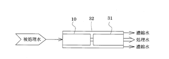
- FIG. 5 although it was set as the water treatment apparatus which provided the filtration apparatus 10 and the reverse osmosis membrane apparatus 31 separately, as shown in FIG. 6, as shown in FIG. May be housed in a single hollow container 32 or the like to form an integrated water treatment apparatus. By making it an integrated water treatment device, it is possible to reduce the size and the number of parts. Note that a plurality of filtration devices 10 or reverse osmosis membrane devices 31 may be provided or one by one.
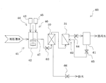
- a water treatment device 40 provided with a coagulation treatment means 41 in the preceding stage of the filtration device 10 may be used.
- the water treatment apparatus 40 introduces chemicals into the reaction tank 42 from a reaction tank 42 into which water to be treated (raw water) is introduced and a chemical tank 43 in which chemicals such as a polymer flocculant are held.
- a coagulation treatment unit 41 comprising an inorganic coagulant introduction unit 46 comprising a chemical introduction unit 44 comprising a pump and the like, and an inorganic coagulant agent tank 45 holding an inorganic coagulant from the inorganic coagulant tank 45 into the reaction vessel 42.
- a reverse osmosis membrane device 31 similar to the water treatment device 30 for membrane separation treatment is provided.
- water to be treated (raw water) is introduced into the reaction tank 42.
- a chemical such as a polymer flocculant held in the chemical tank 43 and an inorganic flocculant held in the inorganic flocculant tank 45 are introduced into the reaction tank 42 by the chemical introduction means 44 and the inorganic flocculant introduction means 46.
- the to-be-processed water to which the polymer flocculant and the inorganic flocculant were added is stirred with the stirrer 47, and is agglomerated.
- the water to be treated that has been subjected to the aggregation treatment is discharged from the reaction tank 42 and sent to the filtration device 10.
- water to be treated examples include water containing a humic acid / fulvic acid organic substance, a biological metabolite such as sugar produced by algae, or a synthetic chemical substance such as a surfactant, specifically, industrial water. , City water, well water, river water, lake water, factory wastewater (particularly, biologically treated water obtained by biologically treating wastewater from a factory) and the like.
- the humic substance refers to a corrosive substance generated by the decomposition of plants and the like into microorganisms, and includes humic acid, and the water containing the humic substance is derived from humic substance and / or humic substance. It has a soluble COD component, suspended matter and chromaticity component.
- polymer flocculant to be added to the water to be treated as a flocculant examples include poly (meth) acrylic acid, a copolymer of (meth) acrylic acid and (meth) acrylamide, and anions such as alkali metal salts thereof.
- Organic polymer flocculants nonionic organic polymer flocculants such as poly (meth) acrylamide, dimethylaminoethyl (meth) acrylate or its quaternary ammonium salt, dimethylaminopropyl (meth) acrylamide or its 4 Homopolymers composed of cationic monomers such as quaternary ammonium salts, and cationic organic polymer flocculants such as copolymers of nonionic monomers copolymerizable with these cationic monomers, and the above anionic monomers, Copolymerization with cationic monomers and nonionic monomers copolymerizable with these monomers
- Organic polymer flocculant of amphoteric is united and the like.
- the amount of the polymer flocculant added is not particularly limited and may be adjusted according to the properties of the water to be treated, but is generally 0.01 to 10 mg / L in solid content with respect to the water to be treated.
- the inorganic flocculant added to the water to be treated is not particularly limited, and examples thereof include aluminum salts such as sulfate bands and polyaluminum chloride, and iron salts such as ferric chloride and ferrous sulfate. Further, the amount of the inorganic flocculant added is not particularly limited, and may be adjusted according to the properties of the water to be treated, but is generally 0.5 to 10 mg / L in terms of aluminum or iron with respect to the water to be treated. It is.
- the pH of the water to be treated to which the polymer flocculant and the inorganic flocculant are added is pH 5.0-7. If it is about 0.0, aggregation is optimal.
- the inorganic flocculant may be added before or after the polymer flocculant is added to the water to be treated, or may be added simultaneously with the polymer flocculant.
- the light absorbency measurement means 51 which measures the light absorbency of to-be-processed water in the raw
- the absorbance data measured by the absorbance measuring means 51 is received, and the amount of the polymer flocculant to be introduced from the chemical tank 43 into the reaction tank 42 and the inorganic flocculant tank 45 into the reaction tank 42 are introduced.
- the water treatment apparatus 50 may be provided with an addition amount control means 52 that calculates the addition amount of the inorganic flocculant and controls the addition amount.
- the addition amount control means 52 preliminarily treats the water to be treated having various absorbances having different water qualities with a jar tester using the polymer flocculant, so that the absorbance of the water to be treated and the optimum addition amount of the polymer flocculant are determined. Is obtained as addition amount correction information.
- the addition amount control means 52 calculates the optimum addition amount from the absorbance data of the water to be treated (raw water) measured by the absorbance measurement means 51 and this relational expression (addition amount correction information). The amount of the polymer flocculant introduced is controlled.
- the addition amount control means 52 preliminarily treats the water to be treated having various absorbances with different water quality using an inorganic flocculant, so that the absorbance of the water to be treated and the optimum addition amount of the inorganic flocculant are determined. Is obtained as addition amount correction information.
- the addition amount control means 52 calculates the optimum addition amount from the absorbance data of the water to be treated (raw water) measured by the absorbance measurement means 51 and this relational expression (addition amount correction information), and the inorganic flocculant introduction means. The amount of the inorganic flocculant introduced from 46 is controlled.
- the absorbance of the water to be treated and the addition amount of the polymer flocculant suitable for treating the water to be treated having the absorbance in advance that is, the turbidity.
- the relationship between the addition amount sufficient to agglomerate the soluble organic matter and not excessive is obtained as addition amount control information.
- the absorbance of the water to be treated is measured, and the addition amount of the polymer flocculant is controlled based on the measurement result of the absorbance and the addition amount correction information.
- the concentration of soluble organic matter and the optimal amount of polymer flocculant determined from the time required to filter a certain amount of sample water using a 0.45 ⁇ m membrane filter (KMF value). There is a relationship. Therefore, the optimum addition amount of the polymer flocculant can be estimated by measuring the absorbance of the ultraviolet part and the visible part respectively by one wavelength or more.
- a jar test is performed in advance on water to be treated having different water qualities, for example, water to be treated such as industrial water collected on different days, and ultraviolet absorbance and visible absorbance in the following formula (I) are obtained. And a relational expression (addition amount control information) between the difference between and the optimum addition concentration of the polymer flocculant.
- a to C are constants depending on the water quality such as the concentration of soluble organic matter in the water to be treated
- E260 represents the absorbance at a wavelength of 260 nm
- E660 represents the absorbance at a wavelength of 660 nm.
- the addition amount control information is obtained by calculating the relational expression between the difference between the ultraviolet absorbance and the visible absorbance and the optimum addition concentration of the polymer flocculant, but is not limited thereto.
- threshold control may be used.
- threshold control when the absorbance difference is less than the predetermined value a 1 , the addition concentration of the polymer flocculant is b 1, and when the absorbance difference is the predetermined value a 1 to a 2 , the addition concentration of the polymer flocculant is b 2.
- a polymer flocculant addition concentration of b 3 is exemplified, but the present invention is not limited to this.
- the optimum amount of the polymer flocculant is added to the water to be treated by controlling the amount of the polymer flocculant added based on the amount of the soluble organic matter that becomes the turbidity contained in the water to be treated. Therefore, the water to be treated can be treated efficiently.
- an optimum amount of the polymer flocculant is added according to the quality of the water to be treated after the fluctuation, so that it is possible to stably obtain a treated water with high clarity. it can.
- the control of the addition amount of the inorganic flocculant may be performed in the same manner as the control of the addition amount of the polymer flocculant.
- an optimum amount of polymer can be obtained by measuring the turbidity instead of the absorbance and performing the same control as the above absorbance. Since flocculants and inorganic flocculants can be added to the water to be treated, the water to be treated can be treated efficiently, and even if the water quality of the water to be treated fluctuates, the water to be treated after it has changed Since an optimum amount of a polymer flocculant or an inorganic flocculant is added according to the water quality, it is possible to stably obtain treated water with high clarity. In addition, you may perform both control of the coagulant addition amount according to the light absorbency data of to-be-processed water (raw water), and control of the coagulant addition amount according to the turbidity data of to-be-processed water.
- a washing liquid introducing means for introducing the washing liquid or a mixed liquid of the washing liquid and air into the water treatment apparatus from the direction opposite to the direction of water flow of the water to be treated.
- a water treatment device may be used.
- the water treatment apparatus has a treated water tank 61 that stores treated water that has been treated by the reverse osmosis membrane apparatus 31, and treated water (cleaning liquid) of the treated water tank 61.
- a cleaning liquid introducing means 62 for introducing a mixed liquid (cleaning liquid) of the water to be treated and air into the reverse osmosis membrane device 31 and the filtration device 10.
- the water to be treated that has been subjected to membrane separation after filtration is stored in the treated water tank 61.
- the filter body 2 or the like of the filtration device 10 is attached by the adhering of contaminants such as solid matter and other turbid substances resulting from the polymer flocculant and the inorganic flocculant gradually added as the flocculant by passing the water to be treated.
- Performance deteriorates.
- the separation membrane such as the reverse osmosis membrane of the reverse osmosis membrane device 31 adheres to contaminants such as solid matter and other turbid substances caused by the polymer flocculant and the inorganic flocculant gradually added as the flocculant by the membrane separation treatment.
- the valve 63 provided between the reaction tank 42 and the filtration device 10 and the reverse osmosis membrane device 31 and the like and the treated water tank 61 are opened at an arbitrary frequency and opened during the membrane separation process.
- the valve 64 is closed to interrupt the membrane separation process.
- another valve 65 connecting the treated water tank 61 and the reverse osmosis membrane device 31 is opened, and the treated water stored in the treated water tank 61 and the liquid mixed with air are reversed by the cleaning liquid introducing means 62 such as a pump.
- the separation membrane is flushed with a cleaning solution or air by passing water through the osmotic membrane device 31 in a direction opposite to that during processing, for example, for about 1 minute.
- the filter body 4 or the like is back-washed with the cleaning liquid or air. Then, the cleaning liquid is discharged from the filtration device 10 through the valve 66 to the outside of the water treatment device 60 as waste water. Even if there is no pump or the like for sending the cleaning liquid between the reverse osmosis membrane device 31 and the filtration device 10, the cleaning liquid is introduced into the filtration device 10 by the cleaning liquid introduction means 62 that introduces the cleaning liquid into the reverse osmosis membrane device 31. Can be introduced.
- valves 63 and 64 are opened again, the valves 65 and 66 are closed, and filtration and a membrane separation process are restarted.
- the turbidity adsorbed on the filter body 2 and the separation membrane can be removed by washing the membrane separation processing means such as the filtration device 10 and the reverse osmosis membrane device 31, so that the filtration performance and membrane separation can be reduced. It is possible to reliably suppress performance degradation. In addition, you may make it introduce
- a polymer flocculant and an inorganic flocculant are used as the flocculant, but either one may be used.
- the flocculant is introduced into the reaction tank 42, but may be introduced before the reaction tank 42.
- a water treatment apparatus further having a purification treatment means for treated water, such as decarboxylation treatment or activated carbon treatment, may be used. And it is good also as a water treatment apparatus which comprises an ultraviolet irradiation means, an ozone treatment means, a biological treatment means, etc. as needed.
- a coagulant a bactericidal agent, a deodorant, an antifoaming agent, an anticorrosive, and the like may be added.
- each additive may be added to the chemical tank 43 by mixing. it can.
- FIG. 10 is a longitudinal sectional view showing the configuration of the water treatment device 70 according to Embodiment 3 of the present invention
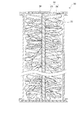
- FIG. 11 is a sectional view showing the configuration of the coarse filtration device 20.
- symbol is attached
- the coarse filtration device 20 and the filtration device 10 of the first embodiment are accommodated in a water treatment vessel 71 in order from the upstream side.
- the coarse filtration apparatus 20 is a cylindrical coarse filtration tank 21 through which water to be treated is passed, and a coarse filter body 22 that captures turbidity in the water to be treated.
- the coarse filter body 22 includes a core member 23 connected to both ends of the coarse filtration tank 21 in the water flow direction, and a string-like turbidity capturing unit 24.
- a circular plate 26 made of resin or the like provided with a plurality of holes to the extent that water to be treated containing turbidity can be freely passed is provided at both ends of the coarse filtration tank 21 in the water passing direction. Both ends of the core material 23 are fixed to the center of the core 26.
- the turbidity capturing unit 24 is provided so that a part of the turbidity capturing unit 24 is braided and fixed to the core member 23 and a so-called loop-shaped part that is not fixed spreads radially toward the inner wall surface of the coarse filtration tank 21.
- the coarse filter 22 is spread over the entire coarse filtration tank 21. For this reason, since the turbidity capturing part 24 intersects with the water flow direction, the turbidity capturing part 24 can capture the turbidity contained in the water to be treated.
- the string-like turbidity capturing part 24 is a long rectangle (tape) formed in a loop shape, and as shown in the enlarged view of the string-like turbidity capturing part 24 in FIG.
- a plurality of slits 25 that do not reach are provided. By providing the slit 25 in this way, the effect of trapping turbidity is improved.
- the coarse filter body 22 is filled in the coarse filter tank 21 so that the porosity of the filtration part when the water to be treated is passed is 50 to 95%, preferably 60 to 90%.
- the porosity is a value obtained from the following formula.
- the filtration part is a region where the turbidity of the water to be treated is captured by the coarse filter 22, that is, the both ends of the coarse filter 22 in the direction of water passage when the inner wall surface of the coarse filter tank 21 is used as a side surface.
- the turbidity trapping portion 24 of the coarse filter 22 as both ends in the thickness direction, it refers to a portion excluding a portion that does not contribute to filtration (a portion of the core material 23 in this embodiment).
- the filtration part uses the inner wall surface of the coarse filtration tank 21 as a side surface, and the coarse filter body 22 at the time of water passage of the coarse filter body 22 at the time of water flow is defined as both ends in the thickness direction.
- the volume of the filtration part—the volume of the turbidity trapping part” is, for example, as shown in this embodiment, when the coarse filter 22 is not consolidated during the filtration operation (when the water to be treated is passed),
- the core material 23 is determined from the amount of the water to be treated which overflows when the coarse filter body 22 is put into the coarse filtration tank 21 filled with the water to be treated. It can be easily obtained by reducing the volume of In the present embodiment, both ends of the coarse filter body 22 are fixed to both ends of the coarse filtration tank 21 in the water flow direction, respectively, and the coarse filter body 22 spreads over the entire coarse filter tank 21 when water to be treated is passed. Therefore, the part which reduced the part of the core material 23 from the whole inside of the coarse filtration tank 21 is a filtration part.
- the water to be treated passes between the string-like turbid traps 24 or between the slits 25 provided in the turbid trap 24.
- the turbidity contained in the water to be treated is trapped in the string-like turbidity capturing unit 24 and the slit 25, and the water to be treated from which the turbidity has been removed is discharged from the coarse filtration tank 21.
- the coarse filter body 22 is filled so that the porosity of the filtration part at the time of water flow is 50 to 95%, water flow is not hindered and turbid trapping is also good.
- the porosity is higher than 95%, the water flow becomes good and it becomes easy to filter at high speed, but the turbidity of the treated water becomes remarkably high, and if it is lower than 50%, the trap of turbidity is good.
- the water flow is insufficient and the coarse filtration device 20, the filtration device 10 provided in the subsequent stage, or the reverse osmosis membrane device 31 may be clogged, and the differential pressure increase rate is significantly increased.
- the turbidity of the treated water is deteriorated or the apparatus is blocked.
- the coarse filtration device 20 filled with the coarse filter body 22 so that the porosity is 50 to 95% the treated water with high turbidity and high speed can be obtained.
- blockage can be suppressed and clear treated water can be obtained.
- the turbidity trapping part 24 is filled up to the vicinity of both ends of the coarse filtration tank 21 in the direction of water flow. It is preferable that the vicinity of the inner wall surface of 21 is filled.
- the volume of the filtration part does not fluctuate between passing water to be treated and other states such as backwashing or stopping filtration, which will be described later, and the volume fluctuation rate of the filtration part is 30%.
- it is preferably 10% or less.
- the diameter of the coarse filtration tank 21 is, for example, a cylinder
- the diameter may be 100 to 1000 mm and the height may be 200 to 1000 mm.
- a plurality of coarse filter bodies 22 are filled in the coarse filter tank 21 or the turbid trapping part 24 of the coarse filter body 22 is enlarged.
- the porosity of the filtration part during water flow may be 50 to 95%.
- the core material 23 and the suspended matter capturing part 24 synthetic resins such as polypropylene, polyester, and nylon can be cited.
- the core material 23 may be provided with strength by knitting synthetic fibers such as polypropylene, polyester, and nylon in the manufacturing process.
- the size of the core material 23 and the turbidity trap 24 is not particularly limited except that the porosity is within the above range.
- the thickness is 0.05 to 2 mm
- the width is 1 to 50 mm
- the length is (Distance from the core material when water to be treated is passed) It can be about 10 to 500 mm, preferably about 0.3 to 2 mm in thickness, 1 to 20 mm in width, and about 50 to 200 mm in length.
- the cylindrical coarse filtration tank 21 is used.
- the cylindrical coarse filtration tank 21 may not be cylindrical, and may have a shape that allows water to pass therethrough, that is, a hollow shape.
- the both ends of the core material 23 were fixed to the plate 26, it is not limited to this, For example, you may make it fix only one end of a core material.
- each turbidity trapping part may be fixed to the core material as a trapping part.
- acquisition part 24 was made into square, there is no limitation in particular, For example, circular shape may be sufficient.
- the length of each turbidity trapping part may be the same or different.
- the material of the turbidity capturing unit 24 is one type, but may be two or more types.
- acquisition part may be plural or single, and does not need to provide.
- the core material 23 may not be sufficient and it is good also as the coarse filter body 22 comprised only by a turbidity capture
- the filtering device 10 shows an example in which the filtering device 10 and the coarse filtering device 20 are integrated, but they may be provided separately and connected by piping or the like.
- the water treatment apparatus 70 which provided the coarse filtration apparatus 20 in the front
- the water treatment apparatus 30 the water treatment apparatus 40, the water treatment apparatus 50, and water of Embodiment 2 are used.
- a water treatment device in which the coarse filtration device 20 is provided in the previous stage of each filtration device 10 may be used.
- Example 1 As treated water (raw water), industrial water with turbidity of 2.0 to 3.0 degrees, residual chlorine (as.Cl 2 ): less than 0.05 ppm, water temperature: 24.5 to 25.5 ° C. is shown in FIG. Using the water treatment device shown, the pressure at the inlet of the reverse osmosis membrane device: 0.75 MPa, the amount of concentrated water discharged from the reverse osmosis membrane device: 1.35 m 3 / h, the amount of treated water: 0.25 m 3 / h The treated water was passed through.
- the configurations of the filtration device 10 and the reverse osmosis membrane device 31 are as follows.
- Filtration tank ... Cylindrical container (vessel) with an inner diameter of 100 mm
- Filter body mesh sheet made of warp and weft made of polyethylene fibers with a diameter of 0.3 mm, 1 m ⁇ 10 m shown in FIG. 4, intersection point height T is 0.85 mm, opening 3000 ⁇ m, opening area
- Water-impermeable member filtration tank
- Reverse osmosis membrane device Reverse osmosis membrane: spiral type (diameter 100 mm) using FILMTEC LE-4040 (height of intersection of raw water flow path spacer: 0.85 mm) manufactured by The Dow Chemical Company
- the differential pressure of the reverse osmosis membrane during the treatment was determined as the difference between the pressure P1 at the inlet of the reverse osmosis membrane device and the pressure P2 at the concentrated water outlet (P1 ⁇ P2 (MPa)). It was confirmed that even if water was passed for a long time, it was almost constant and stable, and blockage was prevented. Thereafter, the pressure increased to 0.2 MPa, and water passage became impossible.
- the number of fine particles of the treated water (raw water) to be introduced into the filtration device 10 and the treated water discharged from the reverse osmosis membrane device 31 after 72 hours from the start of the flow of the treated water is determined by the laser light blocking method.
- the results shown in Table 1 were obtained.
- Example 1 the turbidity of 200 ⁇ m or more was removed, and the turbidity was remarkably removed as compared with Comparative Example 1 in which the filtration device 10 was not used. 1, it was confirmed that the treated water discharged from the filtration device 10 was clear, and as a result, the membrane separation process in the reverse osmosis membrane device 31 was suitably performed.
- Example 1 The same operation as in Example 1 was performed except that the filtration device 10 was not provided and only the reverse osmosis membrane device was used. The measurement results of the number of fine particles and turbidity are shown in Table 1. Further, the differential pressure of the reverse osmosis membrane increased immediately after water flow, and after 24 hours became 0.2 MPa, making water flow impossible.
- Example 2 As a spacer, 1 sheet of 1m x 10m x 0.22mm thick non-woven fabric (FT-330N made by Nippon Vilene) made of 17.5 ⁇ m diameter polyolefin fiber and 1m x 10m made of PET (polyethylene terephthalate) X The same operation as in Example 1 was performed except that one film having a thickness of 0.1 mm (water-impermeable film) was superposed and the four corners were heat-sealed and fixed. The measurement results of the number of fine particles and turbidity are shown in Table 1.
- FT-330N made by Nippon Vilene
- PET polyethylene terephthalate
- Example 2 As a result, it was confirmed that the differential pressure of the reverse osmosis membrane was almost constant and stable even when water was passed for 30 days, and occlusion was prevented for a long time. Further, as shown in Table 1, in Example 2, turbidity of 50 ⁇ m or more was removed, and turbidity was remarkably removed as compared with Comparative Example 1 and Example 1 in which the filtration device 10 was not used. Therefore, in Example 2, the treated water discharged from the filtration device 10 was remarkably clarified, and as a result, it was confirmed that the membrane separation treatment in the subsequent reverse osmosis membrane device 31 was suitably performed. .
- Example 3 As a spacer, 1 mx 10 m x 0.3 mm thick non-woven fabric (Unitika activated carbon fiber A-15) made of activated carbon fiber with a diameter of 15 ⁇ m and PET (polyethylene terephthalate) 1 mx 10 m x thickness The same operation as in Example 1 was performed except that one 0.1 mm film (water-impermeable film) was superposed and the four corners were heat-sealed and fixed. The measurement results of the number of fine particles and turbidity are shown in Table 1. As a result, it was confirmed that the differential pressure of the reverse osmosis membrane was almost constant and stable even when water was passed for 30 days, and occlusion was prevented for a long time.
- Example 3 turbidity of 50 ⁇ m or more was removed, and the turbidity was remarkably removed as compared with Comparative Example 1 and Example 1.
- Example 3 the treated water discharged from the filtration device 10 was remarkably clear, and as a result, it was confirmed that the membrane separation treatment in the reverse osmosis membrane device 31 in the subsequent stage was suitably performed.
- Example 4 As water to be treated (raw water), industrial water having a turbidity of 8.0 to 10 degrees, residual chlorine (as.Cl 2 ) of less than 0.05 ppm, and a water temperature of 24.5 to 25.5 ° C. is shown in FIG.
- a water treatment device provided with the coarse filtration device 20 immediately before the treatment device 40, specifically, a coagulation treatment means 41, the coarse filtration device 20, the filtration device 10, and the reverse osmosis membrane device 31 are provided in this order from the upstream side.
- the pressure at the inlet of the reverse osmosis membrane device 0.75 MPa
- the amount of concentrated water discharged from the reverse osmosis membrane device 1.35 m 3 / h
- the amount of treated water 0.25 m 3 / h
- Treated water was passed through.
- the structure of the aggregation process means 41, the coarse filtration apparatus 20, the filtration apparatus 10, and the reverse osmosis membrane apparatus 31 is as follows.
- ⁇ Coarse filtration device> As shown in FIG. 11, it includes a core material 23 and a string-like turbidity capturing unit 24, and both ends are fixed to plates 26 at both ends of the coarse filtration tank 21 in the water flow direction.
- the core material 23 has a volume of 250 mL, and the thickness of each turbid trap 14 is 0.5 mm, the width is 2 mm, and the length (the distance from the core material when water to be treated is passed) is 100 mm. It is knitted into a core material in a loop shape, and the porosity of the filtration part (water volume obtained by subtracting the volume of the core material 23 from the volume inside the coarse filtration tank 21) is 85%.
- Filtration tank ... Cylindrical container (vessel) with an inner diameter of 100 mm
- Filter body mesh sheet made of warp and weft made of polyethylene fibers with a diameter of 0.3 mm, 1 m ⁇ 10 m shown in FIG.
- intersection point height T is 0.85 mm, opening 3000 ⁇ m, opening area 82% woven fabric, 1m x 10m x 0.22mm thick non-woven fabric (FT-330N made by Nippon Vilene), made of polyolefin fibers with a diameter of 17.5 ⁇ m, and PET (polyethylene terephthalate)
- FT-330N made by Nippon Vilene
- PET polyethylene terephthalate
- Reverse osmosis membrane device Reverse osmosis membrane: spiral type (diameter 100 mm) using FILMTEC LE-4040 (height of intersection of raw water flow path spacer: 0.85 mm) manufactured by The Dow Chemical Company
- the differential pressure of the reverse osmosis membrane during the treatment was determined as a difference between the pressure P1 at the inlet of the reverse osmosis membrane device and the pressure P2 at the concentrated water outlet (P1 ⁇ P2 (MPa)) as shown in FIG. It was confirmed that even if water was passed for a long time, it was almost constant and stable, and blockage was prevented. Thereafter, the pressure increased to 0.2 MPa, and water passage became impossible.
- the number of fine particles of the treated water (raw water) introduced into the aggregating treatment means 41 and the treated water discharged from the reverse osmosis membrane device 31 after 120 hours from the start of passing the treated water is determined by a laser light blocking method.
- the turbidity was determined by a transmitted light measurement method using a kaolin standard solution, the results shown in Table 1 were obtained.
- Table 1 in Example 4, the turbidity of 100 ⁇ m or more was removed, and the turbidity was remarkably removed as compared with Comparative Example 1 in which the filtration device 10 was not used.
- FIG. 4 it was confirmed that the treated water discharged from the filtration device 10 was clear, and as a result, the membrane separation process in the reverse osmosis membrane device 31 was suitably performed.
- Example 5 The treated water and air discharged from the reverse osmosis membrane device 31 are passed through the filtration device 10 and the coarse filtration device 20 in the direction opposite to the water flow direction once every 30 minutes, and the treated water flow rate: 1.6 m 3 / h, air Flow rate: The same operation as in Example 4 was performed except that water was passed at 1.0 Nm 3 / h for 10 minutes.
- the reference example which shows the effect of the coarse filtration apparatus 20 below is shown.
- industrial water having a turbidity of 20 degrees was treated for 1 week at LV 200 m / h using a water treatment apparatus provided with a coagulation treatment means 41 in the previous stage of the coarse filtration apparatus shown in FIG.
- the filter body used in the coarse filtration apparatus is composed of a core material 23 and a string-like turbidity capturing portion 24, and both ends are fixed to plates 26 at both ends of the coarse filtration tank 21 in the water flow direction. Has been.
- the core material 23 has a volume of 250 mL, and the thickness of each turbidity trap 24 is 0.5 mm, width 2 mm, and length (distance from the core material when the water to be treated is passed) is 100 mm.
- the core material is knitted in a loop shape, and the knitting density of the turbidity capturing unit 24 is changed, and the volume of the core material 23 is subtracted from the filtration unit during passage of water (the volume inside the coarse filtration tank 21).
- Filter bodies having a porosity of 30, 40, 50, 60, 70, 80, 90, 95, and 98% were prepared, and each filter body was treated with water.
- the coarse filtration tank 21 has a diameter of 200 mm and a height of 500 mm.
- the flocculant 30 mg / L polyaluminum chloride (PAC: 10 wt% as Al 2 O 3 ) with respect to the water to be treated and 0.7 mg / L amphoteric polymer flocculant with respect to the water to be treated.
- Clivest E851 manufactured by Kurita Kogyo was added.
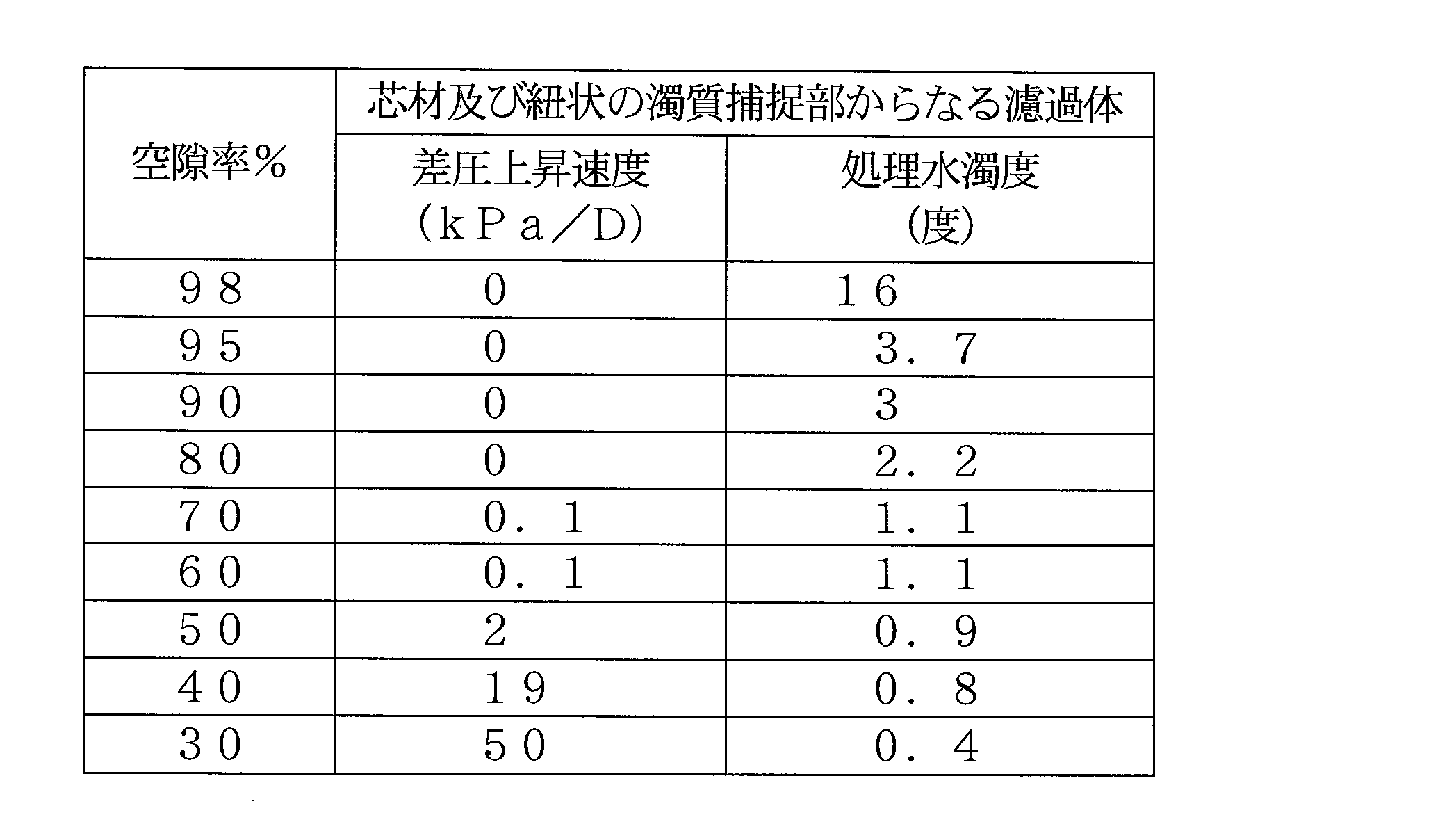
- Table 2 shows the results of measuring the turbidity of the treated water discharged from the coarse filtration apparatus (treated water turbidity) and the differential pressure increase rate (differential pressure increase speed) of the coarse filtration apparatus.
- the turbidity of the treated water was determined by a transmitted light measurement method using a kaolin standard solution, and the differential pressure increase rate of the coarse filtration device was determined by the pressure difference between the inlet and the outlet.
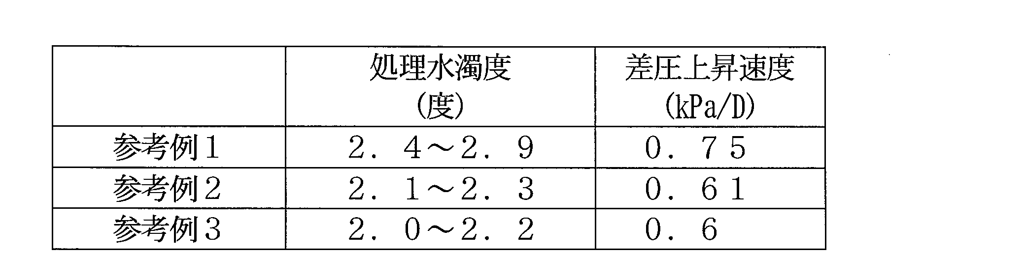
- Table 3 shows the results of measuring the turbidity of the treated water discharged from the coarse filter 20 and the differential pressure increase rate of the coarse filter 20.
- the coarse filtration device 20 has a filter body composed of a core material 23 and a string-like turbidity capturing part 24, and each turbidity capturing part 24 has a thickness of 0.5 mm, a width of 2 mm,
- the porosity of the filtration part (coarse filtration tank 21) at the time of water passage is 85% with a length of 100 mm. Only one end of the core material 23 of the coarse filter 22 is fixed to the upstream plate 26 in the water flow direction.
- the filter body spreads substantially uniformly throughout the entire filtration tank when the treated water flows. Further, polyaluminum chloride (PAC: 10% by weight as Al 2 O 3 ) was added as a flocculant so as to be 30 mg / L with respect to the water to be treated.
- PAC polyaluminum chloride
- Reference Example 2 The same operation as in Reference Example 1 was performed except that 2 to 5 slits were inserted in addition to the portion fixed to the core material of each turbidity trapping portion in the loop shape.
- Reference Example 3 The same operation as in Reference Example 2 was performed except that both ends of the core material 23 of the coarse filter 22 were fixed to the upstream and downstream plates 26 in the water flow direction, respectively.
Landscapes
- Chemical & Material Sciences (AREA)
- Engineering & Computer Science (AREA)
- Water Supply & Treatment (AREA)
- Chemical Kinetics & Catalysis (AREA)
- Nanotechnology (AREA)
- Life Sciences & Earth Sciences (AREA)
- Hydrology & Water Resources (AREA)
- Environmental & Geological Engineering (AREA)
- Organic Chemistry (AREA)
- Separation Using Semi-Permeable Membranes (AREA)
- Separation Of Suspended Particles By Flocculating Agents (AREA)
- Filtration Of Liquid (AREA)
Abstract
Description
(実施形態1)
図1は、本発明の実施形態1に係る濾過装置の構成を示す被処理水の通水方向の縦断面図であり、図2は、横断面図であり、図3は、濾過装置の濾過体を示す斜視図である。
図5は、本発明の実施形態2に係る水処理装置の概略系統図である。なお、実施形態1と同じ部材には同じ符号を付し、重複する説明は省略してある。


図10は、本発明の実施形態3に係る水処理装置70の構成を示す縦断面図であり、図11は、粗濾過装置20の構成を示す断面図である。なお、実施形態1や実施形態2と同じ部材には同じ符号を付し、重複する説明は省略してある。

被処理水(原水)として、濁度2.0~3.0度、残留塩素(as.Cl2):0.05ppm未満、水温:24.5~25.5℃の工業用水を図5に示す水処理装置を用い、逆浸透膜装置の入り口圧力:0.75MPa、逆浸透膜装置から排出される濃縮水量:1.35m3/h、処理水量:0.25m3/hとなる水量で、被処理水を通水して処理した。なお、濾過装置10や、逆浸透膜装置31の構成は以下の通りである。
濾過槽・・・内径100mmの円筒状容器(ベッセル)
濾過体・・・メッシュシートをポリエチレン製の直径0.3mmの繊維からなる縦糸及び横糸で形成された図4に示す1m×10mで交点部の高さTが0.85mm、オープニング3000μm、オープニングエリア82%の織物とし、スペーサーをPET(ポリエチレンテレフタラート)製の1m×10m×厚さ0.1mmのフィルム(水不透過フィルム)とし、これらを重ね合わせて四隅を熱融着したシート状部材を作成し、このシート部材を水不透過フィルムが外側になるようにして直径20mmの塩化ビニル製のパイプ(芯材)に10m巻きつけて形成した、直径100mmの濾過体
水不透過部材:濾過槽の内壁と濾過体本体の外周との隙間や、芯材付近の隙間を、被処理水を通過させない接着剤で充填した
濾過装置の通水量:1.6m3/h(LV=200m/h)
逆浸透膜・・・ザ・ダウ・ケミカル・カンパニー製FILMTEC LE-4040(原水流路スペーサーの交点部の高さ:0.85mm)を用いたスパイラル型のもの(直径100mm)

濾過装置10を設けず、逆浸透膜装置のみとした以外は、実施例1と同様の操作を行った。微粒子数及び濁度の測定結果を表1に示す。また、逆浸透膜の差圧は、通水直後からが上昇し、24時間後には0.2MPaとなり、通水不能になった。
スペーサーとして、直径17.5μmのポレオレフィン系繊維で形成された1m×10m×厚さ0.22mmの不織布(日本バイリーン製 FT-330N)1枚と、PET(ポリエチレンテレフタラート)製の1m×10m×厚さ0.1mmのフィルム(水不透過フィルム)1枚とを重ね合わせて四隅を熱融着して固定したものを用いた以外は、実施例1と同様の操作を行った。微粒子数及び濁度の測定結果を表1に示す。この結果、逆浸透膜の差圧は、30日間通水してもほぼ一定で安定しており、閉塞が長期間防止されることが確認された。また、表1に示すように、実施例2では、50μm以上の濁質が除去されており、濾過装置10を用いなかった比較例1や、実施例1と比べても顕著に濁質が除去されていたことから、実施例2では濾過装置10から排出される処理水が顕著に清澄で、その結果後段の逆浸透膜装置31での膜分離処理が好適に行われたことが確認された。
スペーサーとして、直径15μmの活性炭繊維で形成された1m×10m×厚さ0.3mmの不織布(ユニチカ製活性炭繊維 A-15)1枚と、PET(ポリエチレンテレフタラート)製の1m×10m×厚さ0.1mmのフィルム(水不透過フィルム)1枚とを重ね合わせて四隅を熱融着して固定したものを用いた以外は、実施例1と同様の操作を行った。微粒子数及び濁度の測定結果を表1に示す。この結果、逆浸透膜の差圧は、30日間通水してもほぼ一定で安定しており、閉塞が長期間防止されることが確認された。また、表1に示すように、実施例3では、50μm以上の濁質が除去されており、比較例1や、実施例1と比べても顕著に濁質が除去されていたことから、実施例3では濾過装置10から排出される処理水が顕著に清澄で、その結果後段の逆浸透膜装置31での膜分離処理が好適に行われたことが確認された。
被処理水(原水)として、濁度8.0~10度、残留塩素(as.Cl2):0.05ppm未満、水温:24.5~25.5℃の工業用水を図7に示す水処理装置40の直前に粗濾過装置20を設けた水処理装置、具体的には、上流側から凝集処理手段41、粗濾過装置20、濾過装置10、逆浸透膜装置31が順に設けられている水処理装置を用い、逆浸透膜装置の入り口圧力:0.75MPa、逆浸透膜装置から排出される濃縮水量:1.35m3/h、処理水量:0.25m3/hとなる水量で、被処理水を通水して処理した。なお、凝集処理手段41、粗濾過装置20、濾過装置10や、逆浸透膜装置31の構成は以下の通りである。
凝集剤・・・被処理水に対して30mg/Lのポリ塩化アルミニウム(PAC:10重量% as Al2O3)、及び、被処理水に対してカチオン性高分子凝集剤として1.0ppmのクリフィックスCP604(栗田工業製)を添加
図11に示すように芯材23及び紐状の濁質捕捉部24からなり、粗濾過槽21の通水方向両端のプレート26にそれぞれ両端が固定されている。そして、芯材23は体積250mLで、各濁質捕捉部14の厚さは、0.5mm、幅2mm、長さ(被処理水を通水した際の芯材からの距離)100mmとなるようループ状に芯材に編みこんだものであり、通水時の濾過部(粗濾過槽21内部の体積から芯材23の体積を引いたもの)の空隙率が、85%である。なお、芯材は両端で固定しているため、被処理水通水時とその他の時とでは濾過部の体積変化率はほぼ0%であった。また、粗濾過槽21の大きさは、直径200mm、高さ500mmである。
粗濾過装置の通水量:1.6m3/h(LV=200m/h)
濾過槽・・・内径100mmの円筒状容器(ベッセル)
濾過体・・・メッシュシートをポリエチレン製の直径0.3mmの繊維からなる縦糸及び横糸で形成された図4に示す1m×10mで交点部の高さTが0.85mm、オープニング3000μm、オープニングエリア82%の織物とし、スペーサーを直径17.5μmのポレオレフィン系繊維で形成された1m×10m×厚さ0.22mmの不織布(日本バイリーン製 FT-330N)1枚と、PET(ポリエチレンテレフタラート)製の1m×10m×厚さ0.1mmのフィルム(水不透過フィルム)1枚とを重ね合わせて四隅を熱融着したものとし、これらを重ね合わせて四隅を熱融着したシート状部材を作成し、このシート部材を水不透過フィルムが外側になるようにして直径20mmの塩化ビニル製のパイプ(芯材)に10m巻きつけて形成した、直径100mmの濾過体
水不透過部材:濾過槽の内壁と濾過体本体の外周との隙間や、芯材付近の隙間を、被処理水を通過させない接着剤で充填した
濾過装置の通水量:1.6m3/h(LV=200m/h)
逆浸透膜・・・ザ・ダウ・ケミカル・カンパニー製FILMTEC LE-4040(原水流路スペーサーの交点部の高さ:0.85mm)を用いたスパイラル型のもの(直径100mm)
逆浸透膜装置31から排出された処理水及び空気を、30分に一度、通水方向とは逆方向に濾過装置10及び粗濾過装置20に、処理水流量:1.6m3/h、空気流量:1.0Nm3/hで10分間通水した以外は、実施例4と同様の操作を行った。
(空隙率と差圧上昇及び処理水濁度の関係)
被処理水(原水)として、濁度20度の工業用水を、図11に示す粗濾過装置の前段に凝集処理手段41を設けた水処理装置を用いて、LV200m/hで1週間処理した。なお、粗濾過装置に用いた濾過体は、図11に示すように芯材23及び紐状の濁質捕捉部24からなり、粗濾過槽21の通水方向両端のプレート26にそれぞれ両端が固定されている。そして、芯材23は体積250mLで、各濁質捕捉部24の厚さは、0.5mm、幅2mm、長さ(被処理水を通水した際の芯材からの距離)100mmとなるようループ状に芯材に編みこんだものであり、濁質捕捉部24の編込み密度を変化させて、通水時の濾過部(粗濾過槽21内部の体積から芯材23の体積を引いたもの)の空隙率が、30、40、50、60、70、80、90、95、98%の濾過体を作製し、各濾過体を用いて水処理した。なお、芯材は両端で固定しているため、被処理水通水時とその他の時とでは濾過部の体積変化率はほぼ0%であった。また、粗濾過槽21の大きさは、直径200mm、高さ500mmである。また、凝集剤として、被処理水に対して30mg/Lのポリ塩化アルミニウム(PAC:10重量% as Al2O3)及び被処理水に対して0.7mg/Lの両性の高分子凝集剤クリベストE851(栗田工業製)を添加した。粗濾過装置から排出された処理水の濁度(処理水濁度)及び粗濾過装置の差圧上昇速度(差圧上昇速度)を測定した結果を表2に示す。なお、処理水の濁度はカオリン標準液を用いた透過光測定方法により求め、粗濾過装置の差圧上昇速度は入口と出口の圧力差で求めた。
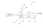
被処理水(原水)として、濁度3.4~22度、TOC(全有機炭素)0.3~4.8mg/L、水温:24.5~26.0℃の工業用水を図16に示す装置(原水の供給水量:50L/h)、具体的には、上流側から順に、凝集処理手段41、粗濾過装置20、膜分離処理手段81が設けられている水処理装置80を用いて、定期的に水質を変動させながら、LV200m/hで処理した。なお、膜分離処理手段81の分離膜として、MF膜を用いた。粗濾過装置20から排出された処理水の濁度及び粗濾過装置20の差圧上昇速度を測定した結果を表3に示す。なお、粗濾過装置20は図11に示すように芯材23及び紐状の濁質捕捉部24からなる濾過体を有し、各濁質捕捉部24の厚さは0.5mm、幅2mm、長さ100mmで、通水時の濾過部(粗濾過槽21)の空隙率は85%である。そして、粗濾過体22の芯材23の一端のみが、通水方向の上流側のプレート26に固定されている。なお、芯材23の一端は固定されていないが、一端が上流側のプレート26に固定されているため、処理水の通水時に濾過体は濾過槽全体に略均一に広がっていた。また、凝集剤としてポリ塩化アルミニウム(PAC:10重量%as Al2O3)を被処理水に対して、30mg/Lとなるように添加した。
ループ形状の各濁質捕捉部の芯材に固定された箇所以外に2~5本のスリットを入れた以外は、参考例1と同様の操作を行った。
粗濾過体22の芯材23の両端をそれぞれ通水方向の上流側及び下流側のプレート26に固定するようにした以外は参考例2と同様の操作を行った。
Claims (11)
- シート状部材が渦巻状に巻回される濾過体本体と、
被処理水が通水され、前記濾過体本体の軸芯が通水方向に沿うように前記濾過体本体が内部に充填される濾過槽とを有し、
前記シート状部材は、被処理水が通過する空孔を有するシート状のメッシュシートと、メッシュシートに比べて被処理水が通過し難いシート状のスペーサーのシート面同士が重ねられたものであること特徴とする濾過装置。 - 前記濾過体本体は、前記シート状部材が芯材に渦巻状に巻回されたものであることを特徴とする請求項1に記載の濾過装置。
- 前記スペーサーが、直径0.1~100μmの繊維で形成された不織布であることを特徴とする請求項1又は2に記載の濾過装置。
- 前記スペーサーが、直径0.1~100μmの活性炭繊維で形成されたものであることを特徴とする請求項1~3の何れかに記載の濾過装置。
- 前記スペーサーが、直径0.1~100μmの繊維で形成された不織布と被処理水を透過しない水不透過シートとからなることを特徴とする請求項1又は2に記載の濾過装置。
- 前記メッシュシートは、直径0.1~0.6mmの繊維で形成されていることを特徴とする請求項1~5の何れかに記載の濾過装置。
- 請求項1~6の何れかに記載の濾過装置の後段に、逆浸透膜装置を有することを特徴とする水処理装置。
- 前記濾過装置の前段に、紐状の濁質捕捉部を有し通水される被処理水中の濁質を捕捉する粗濾過体を通水時の濾過部の空隙率が50~95%となるように粗濾過槽に充填した粗濾過装置を有することを特徴とする請求項7に記載の水処理装置。
- 前記粗濾過装置と前記濾過装置とが一つの容器に収容され、前記粗濾過装置及び前記濾過装置が一体となっていることを特徴とする請求項8に記載の水処理装置。
- 前記濾過装置の前段に、被処理水が導入される反応槽と、凝集剤を前記反応槽又は反応槽の前段で導入して被処理水に前記凝集剤を添加する凝集剤導入手段とを具備する凝集処理手段を有することを特徴とする請求項7~9の何れかに記載の水処理装置。
- 洗浄液又は洗浄液と空気との混合液を、任意の頻度で、処理時とは逆方向から導入する洗浄液導入手段をさらに有することを特徴とする請求項7~10の何れかに記載の水処理装置。
Priority Applications (4)
| Application Number | Priority Date | Filing Date | Title |
|---|---|---|---|
| CN201180011535.3A CN102781539B (zh) | 2010-03-31 | 2011-03-28 | 过滤装置及水处理装置 |
| SG2012055364A SG182740A1 (en) | 2010-03-31 | 2011-03-28 | Filtration apparatus and water treatment apparatus |
| US13/577,442 US20120298570A1 (en) | 2010-03-31 | 2011-03-28 | Filtration apparatus and water treatment apparatus |
| KR1020127021978A KR20130018230A (ko) | 2010-03-31 | 2011-03-28 | 여과 장치 및 수처리 장치 |
Applications Claiming Priority (2)
| Application Number | Priority Date | Filing Date | Title |
|---|---|---|---|
| JP2010081549A JP5561473B2 (ja) | 2010-03-31 | 2010-03-31 | 濾過装置及び水処理装置 |
| JP2010-081549 | 2010-03-31 |
Publications (1)
| Publication Number | Publication Date |
|---|---|
| WO2011125599A1 true WO2011125599A1 (ja) | 2011-10-13 |
Family
ID=44762548
Family Applications (1)
| Application Number | Title | Priority Date | Filing Date |
|---|---|---|---|
| PCT/JP2011/057584 Ceased WO2011125599A1 (ja) | 2010-03-31 | 2011-03-28 | 濾過装置及び水処理装置 |
Country Status (8)
| Country | Link |
|---|---|
| US (1) | US20120298570A1 (ja) |
| JP (1) | JP5561473B2 (ja) |
| KR (1) | KR20130018230A (ja) |
| CN (1) | CN102781539B (ja) |
| MY (1) | MY164518A (ja) |
| SG (1) | SG182740A1 (ja) |
| TW (1) | TWI519336B (ja) |
| WO (1) | WO2011125599A1 (ja) |
Cited By (3)
| Publication number | Priority date | Publication date | Assignee | Title |
|---|---|---|---|---|
| KR101403722B1 (ko) * | 2012-08-16 | 2014-06-03 | 김연중 | 나노기공막 포켓이 장착된 정수기용 멤브레인 필터 |
| US20140346111A1 (en) * | 2011-12-28 | 2014-11-27 | Kurita Water Industries Ltd. | Seawater treatment method |
| TWI478764B (zh) * | 2013-03-06 | 2015-04-01 | Swun Chyan Entpr Co Ltd | Production method of activated carbon composite filter |
Families Citing this family (21)
| Publication number | Priority date | Publication date | Assignee | Title |
|---|---|---|---|---|
| JP5843071B2 (ja) * | 2010-03-30 | 2016-01-13 | 栗田工業株式会社 | 水処理装置 |
| CN103212297B (zh) * | 2013-05-09 | 2014-12-31 | 北京万邦达环保技术股份有限公司 | 过滤方法 |
| CN103212294B (zh) * | 2013-05-09 | 2015-02-18 | 北京万邦达环保技术股份有限公司 | 过滤设备 |
| CN103232120B (zh) * | 2013-05-09 | 2014-12-31 | 北京万邦达环保技术股份有限公司 | 过滤单元 |
| JP6001013B2 (ja) * | 2013-08-13 | 2016-10-05 | 富士フイルム株式会社 | 酸性ガス分離用スパイラル型モジュール |
| US11066311B2 (en) | 2013-12-18 | 2021-07-20 | Brita I.P | Method of using a filter media for filtration |
| HK1224241A1 (zh) | 2013-12-18 | 2017-08-18 | Brita Lp | 用於傾倒時過濾器系統的容器 |
| US10604420B2 (en) | 2013-12-18 | 2020-03-31 | Brita Lp | Method and apparatus for reservoir free and ventless water filtering |
| US10654725B2 (en) | 2013-12-18 | 2020-05-19 | Brita Lp | Filter assembly for filter as you pour filtration |
| US10765973B2 (en) * | 2015-09-30 | 2020-09-08 | Brita Lp | Filter core configuration |
| AU2016332961A1 (en) | 2015-09-30 | 2018-04-05 | Brita Lp | Filter cartridge placement in filter as you pour system |
| AU2016332962A1 (en) | 2015-09-30 | 2018-04-05 | Brita Lp | Filter design with interchangeable core cover |
| KR102316370B1 (ko) * | 2016-08-26 | 2021-10-22 | 가부시키가이샤 로키 테크노 | 통 형상 필터 |
| EP3590589A4 (en) * | 2017-02-28 | 2020-12-09 | Toray Industries, Inc. | FILTER |
| US20200261886A1 (en) * | 2017-09-29 | 2020-08-20 | Toray Industries, Inc. | Filter and fluid separation method |
| ES2965111T3 (es) * | 2018-06-22 | 2024-04-11 | Zodiac Pool Systems Llc | Filtros principalmente para su uso en relación con piscinas y spas |
| KR102770593B1 (ko) * | 2019-03-22 | 2025-02-19 | 주식회사 엘지화학 | 고회수율 역삼투 스페이서 및 엘리먼트 |
| KR102218048B1 (ko) | 2020-04-20 | 2021-02-25 | 오주건설(주) | 수질 안정화를 위한 반응수단을 갖는 수처리 장치 |
| KR102306268B1 (ko) | 2021-02-09 | 2021-09-29 | 오주건설(주) | 유지보수가 용이한 수질 안정화용 수처리 장치 |
| US12486183B2 (en) * | 2021-12-31 | 2025-12-02 | Wuhan University | Carbon fiber filter and regeneration method therefor, and water treatment device |
| CN115006896A (zh) * | 2022-07-04 | 2022-09-06 | 西安热工研究院有限公司 | 一种用于承压容器内的滤布式过滤装置 |
Citations (4)
| Publication number | Priority date | Publication date | Assignee | Title |
|---|---|---|---|---|
| JPH09313812A (ja) * | 1996-05-28 | 1997-12-09 | Wako Sangyo Kk | 渦巻型フィルタエレメント |
| JPH10505542A (ja) * | 1995-06-22 | 1998-06-02 | インスチィチュート テクスチィル デ フランス | 流体成分の物理化学的分離方法 |
| JP2008136915A (ja) * | 2006-11-30 | 2008-06-19 | Fukoku Shigyo Kk | 液体濾過装置 |
| JP2009136777A (ja) * | 2007-12-06 | 2009-06-25 | Kurita Water Ind Ltd | 膜分離装置 |
Family Cites Families (16)
| Publication number | Priority date | Publication date | Assignee | Title |
|---|---|---|---|---|
| US3684096A (en) * | 1970-09-24 | 1972-08-15 | Whirlpool Co | Expandable spiral filter |
| JPS52109669A (en) * | 1976-03-10 | 1977-09-14 | Yuasa Battery Co Ltd | Filter |
| JP2945549B2 (ja) * | 1992-10-29 | 1999-09-06 | オルガノ株式会社 | 発電所補給水の製造装置 |
| JP3434117B2 (ja) * | 1996-03-29 | 2003-08-04 | 住友電気工業株式会社 | ディーゼルエンジン用パティキュレートトラップ |
| US5897779A (en) * | 1997-02-13 | 1999-04-27 | Minnesota Mining And Manufacturing Company | Spiral wound extraction cartridge |
| JPH10263539A (ja) * | 1997-03-28 | 1998-10-06 | Japan Organo Co Ltd | 被処理水の膜処理方法及び膜処理装置 |
| US6454871B1 (en) * | 1997-06-23 | 2002-09-24 | Princeton Trade & Technology, Inc. | Method of cleaning passageways using a mixed phase flow of gas and a liquid |
| JPH11244852A (ja) * | 1998-02-26 | 1999-09-14 | Japan Organo Co Ltd | 淡水化装置及び該淡水化装置で用いられるろ過装置の逆洗方法 |
| US20030006186A1 (en) * | 1998-10-05 | 2003-01-09 | Pulek John L. | Spiral wound depth filter |
| CN2469973Y (zh) * | 2001-01-18 | 2002-01-09 | 游象扬 | 过滤器滤芯 |
| US7267769B2 (en) * | 2004-09-24 | 2007-09-11 | International Environmental Technologies, Llc | Water purification system utilizing a carbon block pre-filter |
| JP2007014902A (ja) * | 2005-07-08 | 2007-01-25 | Mitsubishi Heavy Ind Ltd | 淡水化装置及び淡水化装置の前処理膜の洗浄方法 |
| ATE525118T1 (de) * | 2007-02-14 | 2011-10-15 | Pall Corp | Modul zur verarbeitung eines fluids und herstellungsverfahren dafür |
| WO2009139531A1 (en) * | 2008-05-15 | 2009-11-19 | Woongjincoway Co., Ltd. | Spiral wound type filter cartridge |
| JP2010046627A (ja) * | 2008-08-22 | 2010-03-04 | Toshiba Corp | 浄水前処理システム |
| CN201299997Y (zh) * | 2008-10-23 | 2009-09-02 | 王献州 | 净水器滤芯 |
-
2010
- 2010-03-31 JP JP2010081549A patent/JP5561473B2/ja not_active Expired - Fee Related
-
2011
- 2011-03-28 US US13/577,442 patent/US20120298570A1/en not_active Abandoned
- 2011-03-28 WO PCT/JP2011/057584 patent/WO2011125599A1/ja not_active Ceased
- 2011-03-28 KR KR1020127021978A patent/KR20130018230A/ko not_active Withdrawn
- 2011-03-28 MY MYPI2012003483A patent/MY164518A/en unknown
- 2011-03-28 CN CN201180011535.3A patent/CN102781539B/zh not_active Expired - Fee Related
- 2011-03-28 SG SG2012055364A patent/SG182740A1/en unknown
- 2011-03-30 TW TW100110942A patent/TWI519336B/zh not_active IP Right Cessation
Patent Citations (4)
| Publication number | Priority date | Publication date | Assignee | Title |
|---|---|---|---|---|
| JPH10505542A (ja) * | 1995-06-22 | 1998-06-02 | インスチィチュート テクスチィル デ フランス | 流体成分の物理化学的分離方法 |
| JPH09313812A (ja) * | 1996-05-28 | 1997-12-09 | Wako Sangyo Kk | 渦巻型フィルタエレメント |
| JP2008136915A (ja) * | 2006-11-30 | 2008-06-19 | Fukoku Shigyo Kk | 液体濾過装置 |
| JP2009136777A (ja) * | 2007-12-06 | 2009-06-25 | Kurita Water Ind Ltd | 膜分離装置 |
Cited By (3)
| Publication number | Priority date | Publication date | Assignee | Title |
|---|---|---|---|---|
| US20140346111A1 (en) * | 2011-12-28 | 2014-11-27 | Kurita Water Industries Ltd. | Seawater treatment method |
| KR101403722B1 (ko) * | 2012-08-16 | 2014-06-03 | 김연중 | 나노기공막 포켓이 장착된 정수기용 멤브레인 필터 |
| TWI478764B (zh) * | 2013-03-06 | 2015-04-01 | Swun Chyan Entpr Co Ltd | Production method of activated carbon composite filter |
Also Published As
| Publication number | Publication date |
|---|---|
| KR20130018230A (ko) | 2013-02-20 |
| JP2011212541A (ja) | 2011-10-27 |
| MY164518A (en) | 2017-12-29 |
| CN102781539A (zh) | 2012-11-14 |
| TWI519336B (zh) | 2016-02-01 |
| SG182740A1 (en) | 2012-08-30 |
| TW201200225A (en) | 2012-01-01 |
| CN102781539B (zh) | 2015-08-05 |
| JP5561473B2 (ja) | 2014-07-30 |
| US20120298570A1 (en) | 2012-11-29 |
Similar Documents
| Publication | Publication Date | Title |
|---|---|---|
| JP5561473B2 (ja) | 濾過装置及び水処理装置 | |
| CN100531870C (zh) | 膜组件及水处理系统 | |
| JP6194887B2 (ja) | 淡水製造方法 | |
| KR20110007180A (ko) | 역침투막 모듈의 운전방법 | |
| JP2015009174A (ja) | 水処理システムおよび水処理システムの水処理方法 | |
| JP6183213B2 (ja) | 造水方法および造水装置 | |
| CN108585262A (zh) | 净化水的方法以及适用于所述方法的设备 | |
| US20060096920A1 (en) | System and method for conditioning water | |
| JP2012206008A (ja) | 酸化剤含有水の処理方法及び水処理装置 | |
| WO2012098969A1 (ja) | 膜モジュールの洗浄方法、造水方法および造水装置 | |
| JPWO2014115769A1 (ja) | 淡水製造装置の運転方法 | |
| JP5672447B2 (ja) | ろ過装置及び水処理装置 | |
| Solutions | Filmtec™ reverse osmosis membranes | |
| JPH09248429A (ja) | 分離方法およびその装置 | |
| Oh et al. | Effect of ozone on microfiltration as a pretreatment of seawater reverse osmosis | |
| WO2017159303A1 (ja) | 高硬度排水の処理方法 | |
| Gaid | Drinking Water Treatment, Membranes Applied to Drinking Water and Desalination | |
| JP6164366B2 (ja) | 吸着部材 | |
| JP2011212542A (ja) | 濾過処理手段の逆洗方法及び水処理装置 | |
| WO2007130053A1 (en) | System and method for conditioning water | |
| JP2001239136A (ja) | 処理システムおよびその運転方法 | |
| JP2020104038A (ja) | 水処理システム運転方法及び水処理システム | |
| JP2018061940A (ja) | 水処理方法及び水処理装置 | |
| Cromphout et al. | Design and operation of an ultrafiltration plant for the production of drinking water out of the river Scheldt | |
| Cartwright | Application of membrane separation technologies to wastewater reclamation and reuse |
Legal Events
| Date | Code | Title | Description |
|---|---|---|---|
| WWE | Wipo information: entry into national phase |
Ref document number: 201180011535.3 Country of ref document: CN |
|
| 121 | Ep: the epo has been informed by wipo that ep was designated in this application |
Ref document number: 11765499 Country of ref document: EP Kind code of ref document: A1 |
|
| WWE | Wipo information: entry into national phase |
Ref document number: 13577442 Country of ref document: US |
|
| ENP | Entry into the national phase |
Ref document number: 20127021978 Country of ref document: KR Kind code of ref document: A |
|
| NENP | Non-entry into the national phase |
Ref country code: DE |
|
| 122 | Ep: pct application non-entry in european phase |
Ref document number: 11765499 Country of ref document: EP Kind code of ref document: A1 |