WO2011125591A1 - Permanent magnet and manufacturing method for permanent magnet - Google Patents
Permanent magnet and manufacturing method for permanent magnet Download PDFInfo
- Publication number
- WO2011125591A1 WO2011125591A1 PCT/JP2011/057572 JP2011057572W WO2011125591A1 WO 2011125591 A1 WO2011125591 A1 WO 2011125591A1 JP 2011057572 W JP2011057572 W JP 2011057572W WO 2011125591 A1 WO2011125591 A1 WO 2011125591A1
- Authority
- WO
- WIPO (PCT)
- Prior art keywords
- magnet
- permanent magnet
- sintering
- organometallic compound
- formula
- Prior art date
Links
Images


Classifications
-
- H—ELECTRICITY
- H01—ELECTRIC ELEMENTS
- H01F—MAGNETS; INDUCTANCES; TRANSFORMERS; SELECTION OF MATERIALS FOR THEIR MAGNETIC PROPERTIES
- H01F1/00—Magnets or magnetic bodies characterised by the magnetic materials therefor; Selection of materials for their magnetic properties
- H01F1/01—Magnets or magnetic bodies characterised by the magnetic materials therefor; Selection of materials for their magnetic properties of inorganic materials
- H01F1/03—Magnets or magnetic bodies characterised by the magnetic materials therefor; Selection of materials for their magnetic properties of inorganic materials characterised by their coercivity
- H01F1/032—Magnets or magnetic bodies characterised by the magnetic materials therefor; Selection of materials for their magnetic properties of inorganic materials characterised by their coercivity of hard-magnetic materials
- H01F1/04—Magnets or magnetic bodies characterised by the magnetic materials therefor; Selection of materials for their magnetic properties of inorganic materials characterised by their coercivity of hard-magnetic materials metals or alloys
- H01F1/06—Magnets or magnetic bodies characterised by the magnetic materials therefor; Selection of materials for their magnetic properties of inorganic materials characterised by their coercivity of hard-magnetic materials metals or alloys in the form of particles, e.g. powder
- H01F1/08—Magnets or magnetic bodies characterised by the magnetic materials therefor; Selection of materials for their magnetic properties of inorganic materials characterised by their coercivity of hard-magnetic materials metals or alloys in the form of particles, e.g. powder pressed, sintered, or bound together
- H01F1/086—Magnets or magnetic bodies characterised by the magnetic materials therefor; Selection of materials for their magnetic properties of inorganic materials characterised by their coercivity of hard-magnetic materials metals or alloys in the form of particles, e.g. powder pressed, sintered, or bound together sintered
-
- B—PERFORMING OPERATIONS; TRANSPORTING
- B22—CASTING; POWDER METALLURGY
- B22F—WORKING METALLIC POWDER; MANUFACTURE OF ARTICLES FROM METALLIC POWDER; MAKING METALLIC POWDER; APPARATUS OR DEVICES SPECIALLY ADAPTED FOR METALLIC POWDER
- B22F1/00—Metallic powder; Treatment of metallic powder, e.g. to facilitate working or to improve properties
- B22F1/16—Metallic particles coated with a non-metal
-
- B—PERFORMING OPERATIONS; TRANSPORTING
- B22—CASTING; POWDER METALLURGY
- B22F—WORKING METALLIC POWDER; MANUFACTURE OF ARTICLES FROM METALLIC POWDER; MAKING METALLIC POWDER; APPARATUS OR DEVICES SPECIALLY ADAPTED FOR METALLIC POWDER
- B22F3/00—Manufacture of workpieces or articles from metallic powder characterised by the manner of compacting or sintering; Apparatus specially adapted therefor ; Presses and furnaces
- B22F3/12—Both compacting and sintering
-
- B—PERFORMING OPERATIONS; TRANSPORTING
- B22—CASTING; POWDER METALLURGY
- B22F—WORKING METALLIC POWDER; MANUFACTURE OF ARTICLES FROM METALLIC POWDER; MAKING METALLIC POWDER; APPARATUS OR DEVICES SPECIALLY ADAPTED FOR METALLIC POWDER
- B22F9/00—Making metallic powder or suspensions thereof
- B22F9/02—Making metallic powder or suspensions thereof using physical processes
- B22F9/04—Making metallic powder or suspensions thereof using physical processes starting from solid material, e.g. by crushing, grinding or milling
-
- C—CHEMISTRY; METALLURGY
- C22—METALLURGY; FERROUS OR NON-FERROUS ALLOYS; TREATMENT OF ALLOYS OR NON-FERROUS METALS
- C22C—ALLOYS
- C22C33/00—Making ferrous alloys
- C22C33/02—Making ferrous alloys by powder metallurgy
- C22C33/0257—Making ferrous alloys by powder metallurgy characterised by the range of the alloying elements
- C22C33/0278—Making ferrous alloys by powder metallurgy characterised by the range of the alloying elements with at least one alloying element having a minimum content above 5%
-
- C—CHEMISTRY; METALLURGY
- C22—METALLURGY; FERROUS OR NON-FERROUS ALLOYS; TREATMENT OF ALLOYS OR NON-FERROUS METALS
- C22C—ALLOYS
- C22C38/00—Ferrous alloys, e.g. steel alloys
- C22C38/002—Ferrous alloys, e.g. steel alloys containing In, Mg, or other elements not provided for in one single group C22C38/001 - C22C38/60
-
- H—ELECTRICITY
- H01—ELECTRIC ELEMENTS
- H01F—MAGNETS; INDUCTANCES; TRANSFORMERS; SELECTION OF MATERIALS FOR THEIR MAGNETIC PROPERTIES
- H01F1/00—Magnets or magnetic bodies characterised by the magnetic materials therefor; Selection of materials for their magnetic properties
- H01F1/01—Magnets or magnetic bodies characterised by the magnetic materials therefor; Selection of materials for their magnetic properties of inorganic materials
- H01F1/03—Magnets or magnetic bodies characterised by the magnetic materials therefor; Selection of materials for their magnetic properties of inorganic materials characterised by their coercivity
- H01F1/032—Magnets or magnetic bodies characterised by the magnetic materials therefor; Selection of materials for their magnetic properties of inorganic materials characterised by their coercivity of hard-magnetic materials
- H01F1/04—Magnets or magnetic bodies characterised by the magnetic materials therefor; Selection of materials for their magnetic properties of inorganic materials characterised by their coercivity of hard-magnetic materials metals or alloys
- H01F1/047—Alloys characterised by their composition
- H01F1/053—Alloys characterised by their composition containing rare earth metals
- H01F1/055—Alloys characterised by their composition containing rare earth metals and magnetic transition metals, e.g. SmCo5
- H01F1/057—Alloys characterised by their composition containing rare earth metals and magnetic transition metals, e.g. SmCo5 and IIIa elements, e.g. Nd2Fe14B
- H01F1/0571—Alloys characterised by their composition containing rare earth metals and magnetic transition metals, e.g. SmCo5 and IIIa elements, e.g. Nd2Fe14B in the form of particles, e.g. rapid quenched powders or ribbon flakes
- H01F1/0572—Alloys characterised by their composition containing rare earth metals and magnetic transition metals, e.g. SmCo5 and IIIa elements, e.g. Nd2Fe14B in the form of particles, e.g. rapid quenched powders or ribbon flakes with a protective layer
-
- H—ELECTRICITY
- H01—ELECTRIC ELEMENTS
- H01F—MAGNETS; INDUCTANCES; TRANSFORMERS; SELECTION OF MATERIALS FOR THEIR MAGNETIC PROPERTIES
- H01F1/00—Magnets or magnetic bodies characterised by the magnetic materials therefor; Selection of materials for their magnetic properties
- H01F1/01—Magnets or magnetic bodies characterised by the magnetic materials therefor; Selection of materials for their magnetic properties of inorganic materials
- H01F1/03—Magnets or magnetic bodies characterised by the magnetic materials therefor; Selection of materials for their magnetic properties of inorganic materials characterised by their coercivity
- H01F1/032—Magnets or magnetic bodies characterised by the magnetic materials therefor; Selection of materials for their magnetic properties of inorganic materials characterised by their coercivity of hard-magnetic materials
- H01F1/04—Magnets or magnetic bodies characterised by the magnetic materials therefor; Selection of materials for their magnetic properties of inorganic materials characterised by their coercivity of hard-magnetic materials metals or alloys
- H01F1/047—Alloys characterised by their composition
- H01F1/053—Alloys characterised by their composition containing rare earth metals
- H01F1/055—Alloys characterised by their composition containing rare earth metals and magnetic transition metals, e.g. SmCo5
- H01F1/057—Alloys characterised by their composition containing rare earth metals and magnetic transition metals, e.g. SmCo5 and IIIa elements, e.g. Nd2Fe14B
- H01F1/0571—Alloys characterised by their composition containing rare earth metals and magnetic transition metals, e.g. SmCo5 and IIIa elements, e.g. Nd2Fe14B in the form of particles, e.g. rapid quenched powders or ribbon flakes
- H01F1/0575—Alloys characterised by their composition containing rare earth metals and magnetic transition metals, e.g. SmCo5 and IIIa elements, e.g. Nd2Fe14B in the form of particles, e.g. rapid quenched powders or ribbon flakes pressed, sintered or bonded together
- H01F1/0577—Alloys characterised by their composition containing rare earth metals and magnetic transition metals, e.g. SmCo5 and IIIa elements, e.g. Nd2Fe14B in the form of particles, e.g. rapid quenched powders or ribbon flakes pressed, sintered or bonded together sintered
-
- H—ELECTRICITY
- H01—ELECTRIC ELEMENTS
- H01F—MAGNETS; INDUCTANCES; TRANSFORMERS; SELECTION OF MATERIALS FOR THEIR MAGNETIC PROPERTIES
- H01F41/00—Apparatus or processes specially adapted for manufacturing or assembling magnets, inductances or transformers; Apparatus or processes specially adapted for manufacturing materials characterised by their magnetic properties
- H01F41/02—Apparatus or processes specially adapted for manufacturing or assembling magnets, inductances or transformers; Apparatus or processes specially adapted for manufacturing materials characterised by their magnetic properties for manufacturing cores, coils, or magnets
- H01F41/0253—Apparatus or processes specially adapted for manufacturing or assembling magnets, inductances or transformers; Apparatus or processes specially adapted for manufacturing materials characterised by their magnetic properties for manufacturing cores, coils, or magnets for manufacturing permanent magnets
- H01F41/0266—Moulding; Pressing
-
- H—ELECTRICITY
- H01—ELECTRIC ELEMENTS
- H01F—MAGNETS; INDUCTANCES; TRANSFORMERS; SELECTION OF MATERIALS FOR THEIR MAGNETIC PROPERTIES
- H01F41/00—Apparatus or processes specially adapted for manufacturing or assembling magnets, inductances or transformers; Apparatus or processes specially adapted for manufacturing materials characterised by their magnetic properties
- H01F41/02—Apparatus or processes specially adapted for manufacturing or assembling magnets, inductances or transformers; Apparatus or processes specially adapted for manufacturing materials characterised by their magnetic properties for manufacturing cores, coils, or magnets
- H01F41/0253—Apparatus or processes specially adapted for manufacturing or assembling magnets, inductances or transformers; Apparatus or processes specially adapted for manufacturing materials characterised by their magnetic properties for manufacturing cores, coils, or magnets for manufacturing permanent magnets
- H01F41/0293—Apparatus or processes specially adapted for manufacturing or assembling magnets, inductances or transformers; Apparatus or processes specially adapted for manufacturing materials characterised by their magnetic properties for manufacturing cores, coils, or magnets for manufacturing permanent magnets diffusion of rare earth elements, e.g. Tb, Dy or Ho, into permanent magnets
-
- B—PERFORMING OPERATIONS; TRANSPORTING
- B22—CASTING; POWDER METALLURGY
- B22F—WORKING METALLIC POWDER; MANUFACTURE OF ARTICLES FROM METALLIC POWDER; MAKING METALLIC POWDER; APPARATUS OR DEVICES SPECIALLY ADAPTED FOR METALLIC POWDER
- B22F9/00—Making metallic powder or suspensions thereof
- B22F9/02—Making metallic powder or suspensions thereof using physical processes
- B22F9/04—Making metallic powder or suspensions thereof using physical processes starting from solid material, e.g. by crushing, grinding or milling
- B22F2009/042—Making metallic powder or suspensions thereof using physical processes starting from solid material, e.g. by crushing, grinding or milling using a particular milling fluid
-
- B—PERFORMING OPERATIONS; TRANSPORTING
- B22—CASTING; POWDER METALLURGY
- B22F—WORKING METALLIC POWDER; MANUFACTURE OF ARTICLES FROM METALLIC POWDER; MAKING METALLIC POWDER; APPARATUS OR DEVICES SPECIALLY ADAPTED FOR METALLIC POWDER
- B22F2998/00—Supplementary information concerning processes or compositions relating to powder metallurgy
- B22F2998/10—Processes characterised by the sequence of their steps
-
- B—PERFORMING OPERATIONS; TRANSPORTING
- B22—CASTING; POWDER METALLURGY
- B22F—WORKING METALLIC POWDER; MANUFACTURE OF ARTICLES FROM METALLIC POWDER; MAKING METALLIC POWDER; APPARATUS OR DEVICES SPECIALLY ADAPTED FOR METALLIC POWDER
- B22F2999/00—Aspects linked to processes or compositions used in powder metallurgy
Definitions
- the permanent magnet according to the present invention is characterized in that R in the structural formula M- (OR) x is an alkyl group.
- the permanent magnet according to the present invention is characterized in that the amount of carbon remaining after sintering is less than 0.2 wt%.
- the method for producing a permanent magnet according to the present invention is characterized in that R in the structural formula M- (OR) x is an alkyl group.
- the magnet powder is calcined in a hydrogen atmosphere. In this case, it is possible to perform thermal decomposition of the organometallic compound at a low temperature. As a result, the pyrolysis of the organometallic compound can be more easily performed on the entire magnet powder.
- FIG. 1 is an overall view showing a permanent magnet according to the present invention.
- FIG. 2 is an enlarged schematic view showing the vicinity of the grain boundary of the permanent magnet according to the present invention.
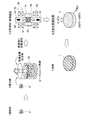
- FIG. 3 is an explanatory view showing a manufacturing process in the first method for manufacturing a permanent magnet according to the present invention.
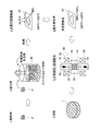
- FIG. 4 is an explanatory view showing a manufacturing process in the second method for manufacturing a permanent magnet according to the present invention.
- FIG. 5 is a diagram showing a change in the amount of oxygen when the calcination treatment in hydrogen is performed and when it is not performed.
- FIG. 6 is a diagram showing the amount of carbon remaining in the permanent magnets of the permanent magnets of Examples 1 to 3 and Comparative Examples 1 to 3.
- Dy or Tb can be unevenly distributed in the grain boundaries of the magnet particles. Then, Dy and Tb unevenly distributed at the grain boundaries suppress the generation of reverse magnetic domains at the grain boundaries, so that the coercive force can be improved. In addition, the amount of Dy or Tb added can be reduced as compared with the conventional case, and a decrease in residual magnetic flux density can be suppressed.
- FIG. 10 is a diagram showing an SEM photograph after sintering of the permanent magnet of Example 3 and the elemental analysis results of the grain boundary phase.
- FIG. 11 is a diagram in which the Tb element distribution state is mapped in the same field of view as the SEM photograph and the SEM photograph after sintering of the permanent magnet of Example 3.
- Dy as an oxide or non-oxide is detected from the grain boundary phase. That is, in the permanent magnets of Examples 1 to 3, Dy diffuses from the grain boundary phase to the main phase, and in the surface portion (outer shell) of the main phase particles, a phase in which a part of Nd is substituted with Dy is the main phase. It turns out that it is produced
- the permanent magnet 1 is manufactured by performing vacuum sintering or pressure sintering.
- the organic compound remaining before sintering is pyrolyzed to burn out the carbon contained in the magnet particles in advance (reduce the carbon content).
- the carbide is hardly formed in the sintering process.
- a large number of ⁇ Fe is not precipitated in the main phase of the magnet after sintering, and the magnet characteristics are not greatly deteriorated.
Abstract
Description
また、本発明に係る永久磁石によれば、製造過程で希土類元素が酸素や炭素と結び付いたとしても、化学量論組成に対して希土類元素が不足することなく、焼結後の永久磁石中にαFeが生成されることを抑制することが可能となる。また、粉砕前後で磁石組成が大きく変動しないので粉砕後に磁石組成を変更する必要なく、製造工程を簡略化することができる。 According to the permanent magnet according to the present invention having the above-described configuration, by calcining a compact of magnet powder mixed with an organic solvent in wet pulverization, which is a manufacturing process of a permanent magnet, in a hydrogen atmosphere before sintering, The amount of carbon contained in the magnet particles can be reduced in advance. As a result, it is possible to sinter the entire magnet densely without generating voids between the main phase and the grain boundary phase of the sintered magnet, and to prevent the coercive force from being lowered. . Further, a large number of αFe is not precipitated in the main phase of the magnet after sintering, and the magnet characteristics are not greatly deteriorated.
Further, according to the permanent magnet of the present invention, even if the rare earth element is combined with oxygen or carbon during the production process, the rare earth element is not insufficient with respect to the stoichiometric composition, and the sintered permanent magnet is It is possible to suppress the production of αFe. In addition, since the magnet composition does not fluctuate greatly before and after pulverization, it is not necessary to change the magnet composition after pulverization, and the manufacturing process can be simplified.
また、本発明に係る永久磁石によれば、製造過程で希土類元素が酸素や炭素と結び付いたとしても、化学量論組成に対して希土類元素が不足することなく、焼結後の永久磁石中にαFeが生成されることを抑制することが可能となる。また、粉砕前後で磁石組成が大きく変動しないので粉砕後に磁石組成を変更する必要なく、製造工程を簡略化することができる。
更に、粉末状の磁石粒子に対して仮焼を行うので、成形後の磁石粒子に対して仮焼を行う場合と比較して、有機化合物の熱分解を磁石粒子全体に対してより容易に行うことができる。即ち、仮焼体中の炭素量をより確実に低減させることが可能となる。 Moreover, according to the permanent magnet according to the present invention, the magnet powder containing the organic particles in the wet pulverization that is a manufacturing process of the permanent magnet is calcined in a hydrogen atmosphere before sintering, thereby containing the magnet particles. The amount of carbon can be reduced in advance. As a result, it is possible to sinter the entire magnet densely without generating voids between the main phase and the grain boundary phase of the sintered magnet, and to prevent the coercive force from being lowered. . Further, a large number of αFe is not precipitated in the main phase of the magnet after sintering, and the magnet characteristics are not greatly deteriorated.
Further, according to the permanent magnet of the present invention, even if the rare earth element is combined with oxygen or carbon during the production process, the rare earth element is not insufficient with respect to the stoichiometric composition, and the sintered permanent magnet is It is possible to suppress the production of αFe. In addition, since the magnet composition does not fluctuate greatly before and after pulverization, it is not necessary to change the magnet composition after pulverization, and the manufacturing process can be simplified.
Furthermore, since the powdered magnet particles are calcined, the organic compound is more easily pyrolyzed with respect to the whole magnet particles as compared with the case of calcining the molded magnet particles. be able to. That is, the amount of carbon in the calcined body can be reduced more reliably.
また、本発明に係る永久磁石の製造方法によれば、製造過程で希土類元素が酸素や炭素と結び付いたとしても、化学量論組成に対して希土類元素が不足することなく、焼結後の永久磁石中にαFeが生成されることを抑制することが可能となる。また、粉砕前後で磁石組成が大きく変動しないので粉砕後に磁石組成を変更する必要なく、製造工程を簡略化することができる。 Further, according to the method for producing a permanent magnet according to the present invention, the carbon powder contained in the magnet particles is obtained by calcining a compact of a magnet powder mixed with an organic solvent in wet pulverization in a hydrogen atmosphere before sintering. The amount can be reduced in advance. As a result, it is possible to sinter the entire magnet densely without generating voids between the main phase and the grain boundary phase of the sintered magnet, and to prevent the coercive force from being lowered. . Further, a large number of αFe is not precipitated in the main phase of the magnet after sintering, and the magnet characteristics are not greatly deteriorated.
Further, according to the method for producing a permanent magnet according to the present invention, even if the rare earth element is combined with oxygen or carbon in the production process, the rare earth element is not insufficient with respect to the stoichiometric composition, and the permanent magnet after sintering is obtained. It becomes possible to suppress the production of αFe in the magnet. In addition, since the magnet composition does not fluctuate greatly before and after pulverization, it is not necessary to change the magnet composition after pulverization, and the manufacturing process can be simplified.
また、本発明に係る永久磁石の製造方法によれば、製造過程で希土類元素が酸素や炭素と結び付いたとしても、化学量論組成に対して希土類元素が不足することなく、焼結後の永久磁石中にαFeが生成されることを抑制することが可能となる。また、粉砕前後で磁石組成が大きく変動しないので粉砕後に磁石組成を変更する必要なく、製造工程を簡略化することができる。
更に、粉末状の磁石粒子に対して仮焼を行うので、成形後の磁石粒子に対して仮焼を行う場合と比較して、有機化合物の熱分解を磁石粒子全体に対してより容易に行うことができる。即ち、仮焼体中の炭素量をより確実に低減させることが可能となる。 Further, according to the method for producing a permanent magnet according to the present invention, the carbon powder contained in the magnet particles is preliminarily calcined in a hydrogen atmosphere before sintering the magnet powder mixed with the organic solvent in the wet pulverization. Can be reduced. As a result, it is possible to sinter the entire magnet densely without generating voids between the main phase and the grain boundary phase of the sintered magnet, and to prevent the coercive force from being lowered. . Further, a large number of αFe is not precipitated in the main phase of the magnet after sintering, and the magnet characteristics are not greatly deteriorated.
Further, according to the method for producing a permanent magnet according to the present invention, even if the rare earth element is combined with oxygen or carbon in the production process, the rare earth element is not insufficient with respect to the stoichiometric composition, and the permanent magnet after sintering is obtained. It becomes possible to suppress the production of αFe in the magnet. In addition, since the magnet composition does not fluctuate greatly before and after pulverization, it is not necessary to change the magnet composition after pulverization, and the manufacturing process can be simplified.
Furthermore, since the powdered magnet particles are calcined, the organic compound is more easily pyrolyzed with respect to the whole magnet particles as compared with the case of calcining the molded magnet particles. be able to. That is, the amount of carbon in the calcined body can be reduced more reliably.
先ず、本発明に係る永久磁石1の構成について説明する。図1は本発明に係る永久磁石1を示した全体図である。尚、図1に示す永久磁石1は円柱形状を備えるが、永久磁石1の形状は成形に用いるキャビティの形状によって変化する。
本発明に係る永久磁石1としては例えばNd-Fe-B系磁石を用いる。また、図2に示すように、永久磁石1は磁化作用に寄与する磁性相である主相11と、非磁性で希土類元素の濃縮した低融点のMリッチ相12(Mは希土類元素であるNd、Pr、Dy、Tbの内、少なくとも一種を含む。)とが共存する合金である。図2は永久磁石1を構成するNd磁石粒子を拡大して示した図である。 [Configuration of permanent magnet]
First, the configuration of the
For example, an Nd—Fe—B magnet is used as the
(1)融点が低く(約600℃)、焼結時に液相となり、磁石の高密度化、即ち磁化の向上に寄与する。(2)粒界の凹凸を無くし、逆磁区のニュークリエーションサイトを減少させ保磁力を高める。(3)主相を磁気的に絶縁し保磁力を増加する。
従って、焼結後の永久磁石1中におけるMリッチ相12の分散状態が悪いと、局部的な焼結不良、磁性の低下をまねくため、焼結後の永久磁石1中にはMリッチ相12が均一に分散していることが重要となる。 In the
(1) The melting point is low (about 600 ° C.), it becomes a liquid phase during sintering, and contributes to increasing the density of the magnet, that is, improving the magnetization. (2) Eliminate grain boundary irregularities, reduce reverse domain nucleation sites and increase coercivity. (3) The main phase is magnetically insulated to increase the coercive force.
Accordingly, if the dispersion state of the M-
次に、本発明に係る永久磁石1の第1の製造方法について図3を用いて説明する。図3は本発明に係る永久磁石1の第1の製造方法における製造工程を示した説明図である。 [Permanent magnet manufacturing method 1]
Next, the 1st manufacturing method of the
尚、詳細な分散条件は以下の通りである。
・分散装置:ビーズミル
・分散メディア:ジルコニアビーズ Next, the coarsely pulverized
Detailed dispersion conditions are as follows.
・ Dispersion equipment: Bead mill ・ Dispersion media: Zirconia beads
また、成形装置50には一対の磁界発生コイル55、56がキャビティ54の上下位置に配置されており、磁力線をキャビティ54に充填された磁石粉末43に印加する。印加させる磁場は例えば1MA/mとする。 As shown in FIG. 3, the
The
また、湿式法を用いる場合には、キャビティ54に磁場を印加しながらスラリーを注入し、注入途中又は注入終了後に、当初の磁場より強い磁場を印加して湿式成形しても良い。また、加圧方向に対して印加方向が垂直となるように磁界発生コイル55、56を配置しても良い。 And when compacting, first, the dried
Further, when using the wet method, the slurry may be injected while applying a magnetic field to the
次に、本発明に係る永久磁石1の他の製造方法である第2の製造方法について図4を用いて説明する。図4は本発明に係る永久磁石1の第2の製造方法における製造工程を示した説明図である。 [Permanent magnet manufacturing method 2]
Next, the 2nd manufacturing method which is another manufacturing method of the
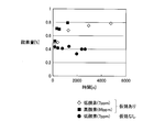
図5は水素中仮焼処理をしたNd磁石粉末と水素中仮焼処理をしていないNd磁石粉末とを、酸素濃度7ppm及び酸素濃度66ppmの雰囲気にそれぞれ暴露した際に、暴露時間に対する磁石粉末内の酸素量を示した図である。図5に示すように水素中仮焼処理した磁石粉末は、高酸素濃度66ppm雰囲気におかれると、約1000secで磁石粉末内の酸素量が0.4%から0.8%まで上昇する。また、低酸素濃度7ppm雰囲気におかれても、約5000secで磁石粉末内の酸素量が0.4%から同じく0.8%まで上昇する。そして、Ndが酸素と結び付くと、残留磁束密度や保磁力の低下の原因となる。
そこで、上記脱水素処理では、水素中仮焼処理によって生成された仮焼体82中のNdH3(活性度大)を、NdH3(活性度大)→NdH2(活性度小)へと段階的に変化させることによって、水素仮焼中処理により活性化された仮焼体82の活性度を低下させる。それによって、水素中仮焼処理によって仮焼された仮焼体82をその後に大気中へと移動させた場合であっても、Ndが酸素と結び付くことを防止し、残留磁束密度や保磁力を低下させることが無い。 Here, the
FIG. 5 shows the magnet powder with respect to the exposure time when the Nd magnet powder subjected to the calcination treatment in hydrogen and the Nd magnet powder not subjected to the calcination treatment in hydrogen are respectively exposed to an atmosphere having an oxygen concentration of 7 ppm and an oxygen concentration of 66 ppm. It is the figure which showed the amount of oxygen in the inside. As shown in FIG. 5, when the magnet powder calcined in hydrogen is placed in an atmosphere having a high oxygen concentration of 66 ppm, the oxygen content in the magnet powder increases from 0.4% to 0.8% in about 1000 seconds. Even in an atmosphere with a low oxygen concentration of 7 ppm, the oxygen content in the magnet powder rises from 0.4% to 0.8% in about 5000 seconds. When Nd is combined with oxygen, it causes a decrease in residual magnetic flux density and coercive force.
Stage Therefore, the dehydrogenation process, NdH 3 calcined body of 82 produced by calcination process in hydrogen (activity Univ), NdH 3 (activity Univ) → NdH 2 to (activity small) Thus, the activity of the
一方、第1の製造方法では、成形体71は水素仮焼後に外気と触れさせることなく焼成に移るため、脱水素工程は不要となる。従って、前記第2の製造方法と比較して製造工程を簡略化することが可能となる。但し、前記第2の製造方法においても、水素仮焼後に外気と触れさせることがなく焼成を行う場合には、脱水素工程は不要となる。 In the second manufacturing method described above, since the powdered magnet particles are calcined in hydrogen, the first manufacturing method in which the magnet particles after molding are calcined in hydrogen are used. In comparison, there is an advantage that the thermal decomposition of the remaining organic compound can be more easily performed on the entire magnet particle. That is, it becomes possible to more reliably reduce the amount of carbon in the calcined body as compared with the first manufacturing method.
On the other hand, in the first manufacturing method, the molded
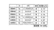
(実施例1)
実施例1のネオジム磁石粉末の合金組成は、化学量論組成に基づく分率(Nd:26.7wt%、Fe(電解鉄):72.3wt%、B:1.0wt%)よりもNdの比率を高くし、例えばwt%でNd/Fe/B=32.7/65.96/1.34とする。また、ビーズミル粉砕時において溶媒に添加する有機金属化合物としてジスプロシウムn-プロポキシドを5wt%添加した。また、湿式粉砕を行う際の有機溶媒としてトルエンを用いた。また、仮焼処理は、成形前の磁石粉末を水素雰囲気において600℃で5時間保持することにより行った。仮焼中の水素の供給量は5L/minとする。また、成形された仮焼体の焼結はSPS焼結により行った。尚、他の工程は上述した[永久磁石の製造方法2]と同様の工程とする。 Examples of the present invention will be described below in comparison with comparative examples.
Example 1
The alloy composition of the neodymium magnet powder of Example 1 is Nd more than the fraction based on the stoichiometric composition (Nd: 26.7 wt%, Fe (electrolytic iron): 72.3 wt%, B: 1.0 wt%). For example, Nd / Fe / B = 32.7 / 65.96 / 1.34 at wt%. Further, 5 wt% of dysprosium n-propoxide was added as an organometallic compound to be added to the solvent during bead mill grinding. In addition, toluene was used as an organic solvent for wet grinding. The calcination treatment was performed by holding the magnet powder before molding at 600 ° C. for 5 hours in a hydrogen atmosphere. The amount of hydrogen supplied during calcination is 5 L / min. Further, the sintered calcined body was sintered by SPS sintering. The other steps are the same as those in [Permanent magnet manufacturing method 2] described above.
添加する有機金属化合物をテルビウムエトキシドとした。他の条件は実施例1と同様である。 (Example 2)
The organometallic compound to be added was terbium ethoxide. Other conditions are the same as in the first embodiment.
添加する有機金属化合物をジスプロシウムエトキシドとした。他の条件は実施例1と同様である。 (Example 3)
The organometallic compound to be added was dysprosium ethoxide. Other conditions are the same as in the first embodiment.
成形された仮焼体の焼結をSPS焼結の代わりに真空焼結により行った。他の条件は実施例1と同様である。 Example 4
The molded calcined body was sintered by vacuum sintering instead of SPS sintering. Other conditions are the same as in the first embodiment.
添加する有機金属化合物をジスプロシウムn-プロポキシドとし、水素中仮焼処理を行わずに焼結した。他の条件は実施例1と同様である。 (Comparative Example 1)
The organometallic compound to be added was dysprosium n-propoxide, which was sintered without calcination in hydrogen. Other conditions are the same as in the first embodiment.
添加する有機金属化合物をテルビウムエトキシドとし、水素中仮焼処理を行わずに焼結した。他の条件は実施例1と同様である。 (Comparative Example 2)
The organometallic compound to be added was terbium ethoxide, and sintering was performed without performing a calcination treatment in hydrogen. Other conditions are the same as in the first embodiment.
添加する有機金属化合物をジスプロシウムアセチルアセトナートとした。他の条件は実施例1と同様である。 (Comparative Example 3)
The organometallic compound to be added was dysprosium acetylacetonate. Other conditions are the same as in the first embodiment.
仮焼処理を水素雰囲気ではなくHe雰囲気で行った。また、成形された仮焼体の焼結をSPS焼結の代わりに真空焼結により行った。他の条件は実施例1と同様である。 (Comparative Example 4)
The calcination treatment was performed in a He atmosphere instead of a hydrogen atmosphere. Further, the sintered calcined body was sintered by vacuum sintering instead of SPS sintering. Other conditions are the same as in the first embodiment.
仮焼処理を水素雰囲気ではなく真空雰囲気で行った。また、成形された仮焼体の焼結をSPS焼結の代わりに真空焼結により行った。他の条件は実施例1と同様である。 (Comparative Example 5)
The calcination treatment was performed in a vacuum atmosphere instead of a hydrogen atmosphere. Further, the sintered calcined body was sintered by vacuum sintering instead of SPS sintering. Other conditions are the same as in the first embodiment.
図6は実施例1~3と比較例1~3の永久磁石の永久磁石中の残存炭素量[wt%]をそれぞれ示した図である。
図6に示すように、実施例1~3は比較例1~3と比較して磁石粒子中に残存する炭素量を大きく低減させることができることが分かる。特に、実施例1~3では、磁石粒子中に残存する炭素量を0.2wt%未満とすることができる。 (Comparison study of residual carbon amount in Examples and Comparative Examples)
FIG. 6 is a graph showing the residual carbon amount [wt%] in the permanent magnets of Examples 1 to 3 and Comparative Examples 1 to 3.
As shown in FIG. 6, it can be seen that Examples 1 to 3 can greatly reduce the amount of carbon remaining in the magnet particles as compared with Comparative Examples 1 to 3. In particular, in Examples 1 to 3, the amount of carbon remaining in the magnet particles can be less than 0.2 wt%.
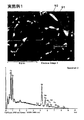
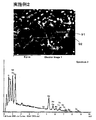
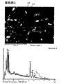
実施例1~3の永久磁石についてXMAによる表面分析を行った。図7は実施例1の永久磁石の焼結後のSEM写真及び粒界相の元素分析結果を示した図である。図8は実施例1の永久磁石の焼結後のSEM写真及びSEM写真と同一視野でDy元素の分布状態をマッピングした図である。図9は実施例2の永久磁石の焼結後のSEM写真及び粒界相の元素分析結果を示した図である。図10は実施例3の永久磁石の焼結後のSEM写真及び粒界相の元素分析結果を示した図である。図11は実施例3の永久磁石の焼結後のSEM写真及びSEM写真と同一視野でTb元素の分布状態をマッピングした図である。
図7、図9、図10に示すように実施例1~3の各永久磁石では、粒界相から酸化物又は非酸化物としてのDyが検出されている。即ち、実施例1~3の永久磁石では、粒界相から主相へとDyが拡散し、主相粒子の表面部分(外殻)において、Ndの一部をDyで置換した相が主相粒子の表面(粒界)に生成されていることが分かる。 (Examination of surface analysis result by XMA in permanent magnet of example)
The permanent magnets of Examples 1 to 3 were subjected to surface analysis by XMA. FIG. 7 is a view showing an SEM photograph after sintering of the permanent magnet of Example 1 and the elemental analysis results of the grain boundary phase. FIG. 8 is a diagram in which the distribution state of the Dy element is mapped in the same field of view as the SEM photograph after sintering of the permanent magnet of Example 1 and the SEM photograph. FIG. 9 is a diagram showing an SEM photograph after sintering of the permanent magnet of Example 2 and the elemental analysis results of the grain boundary phase. FIG. 10 is a diagram showing an SEM photograph after sintering of the permanent magnet of Example 3 and the elemental analysis results of the grain boundary phase. FIG. 11 is a diagram in which the Tb element distribution state is mapped in the same field of view as the SEM photograph and the SEM photograph after sintering of the permanent magnet of Example 3.
As shown in FIGS. 7, 9, and 10, in each of the permanent magnets of Examples 1 to 3, Dy as an oxide or non-oxide is detected from the grain boundary phase. That is, in the permanent magnets of Examples 1 to 3, Dy diffuses from the grain boundary phase to the main phase, and in the surface portion (outer shell) of the main phase particles, a phase in which a part of Nd is substituted with Dy is the main phase. It turns out that it is produced | generated on the surface (grain boundary) of particle | grains.
以上の結果から、実施例1~3では、磁石の粒界にDyやTbを偏在させることができていることが分かる。 In the mapping diagram of FIG. 8, the white part shows the distribution of the Dy element. Referring to the SEM photograph and mapping diagram of FIG. 8, the white portion (that is, the Dy element) of the mapping diagram is unevenly distributed around the main phase. That is, it can be seen that in the permanent magnet of Example 1, Dy is unevenly distributed at the grain boundaries of the magnet. On the other hand, in the mapping diagram of FIG. 11, the white portion indicates the distribution of the Tb element. Referring to the SEM photograph and mapping diagram of FIG. 11, the white portion of the mapping diagram (that is, the Tb element) is unevenly distributed around the main phase. That is, it can be seen that in the permanent magnet of Example 3, Tb is unevenly distributed at the grain boundaries of the magnet.
From the above results, it can be seen that in Examples 1 to 3, Dy and Tb can be unevenly distributed in the grain boundaries of the magnet.
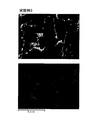
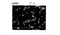
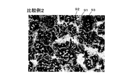
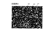
図12は比較例1の永久磁石の焼結後のSEM写真を示した図である。図13は比較例2の永久磁石の焼結後のSEM写真を示した図である。図14は比較例3の永久磁石の焼結後のSEM写真を示した図である。
また、実施例1~3と比較例1~3の各SEM写真を比較すると、残留炭素量が一定量以下(例えば0.2wt%以下)である実施例1~3や比較例1では、基本的にネオジム磁石の主相(Nd2Fe14B)91と白い斑点状に見える粒界相92から焼結後の永久磁石が形成されている。また、少量ではあるがαFe相についても形成されている。それに対して、実施例1~3や比較例1に比べて残留炭素量が多い比較例2、3は、主相91や粒界相92に加えて黒色帯状に見えるαFe相93が多数形成されている。ここで、αFeは焼結時において残留しているカーバイドによって生じるものである。即ち、NdとCとの反応性が非常に高いため、比較例2、3のように焼結工程において高温まで有機化合物中のC含有物が残ると、カーバイドを形成する。その結果、形成されたカーバイドによって焼結後の磁石の主相内にαFeが析出し、磁石特性を大きく低下させることとなる。 (Comparison study of SEM photographs of Examples and Comparative Examples)
FIG. 12 is a view showing an SEM photograph after sintering of the permanent magnet of Comparative Example 1. FIG. 13 is a view showing an SEM photograph after sintering of the permanent magnet of Comparative Example 2. FIG. 14 is an SEM photograph after sintering of the permanent magnet of Comparative Example 3.
Further, when the SEM photographs of Examples 1 to 3 and Comparative Examples 1 to 3 are compared, in Examples 1 to 3 and Comparative Example 1 in which the amount of residual carbon is a certain amount or less (for example, 0.2 wt% or less), In particular, a sintered permanent magnet is formed from a main phase (Nd 2 Fe 14 B) 91 of a neodymium magnet and a
図15は実施例4と比較例4、5の永久磁石について、仮焼温度の条件を変更して製造した複数の永久磁石中の炭素量[wt%]を示した図である。尚、図15では仮焼中の水素及びヘリウムの供給量を1L/minとし、3時間保持した結果を示す。
図15に示すように、He雰囲気や真空雰囲気で仮焼した場合と比較して、水素雰囲気で仮焼した場合には磁石粒子中の炭素量をより大きく低減させることができることが分かる。また、図15からは、磁石粉末を水素雰囲気で仮焼する際の仮焼温度を高温にすれば炭素量がより大きく低減し、特に400℃~900℃とすることによって炭素量を0.2wt%未満とすることが可能であることが分かる。 (Comparison study of examples and comparative examples based on conditions of calcination in hydrogen)
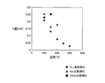
FIG. 15 is a graph showing the carbon amount [wt%] in a plurality of permanent magnets manufactured by changing the calcination temperature conditions for the permanent magnets of Example 4 and Comparative Examples 4 and 5. FIG. 15 shows the result of maintaining the supply amounts of hydrogen and helium during calcination at 1 L / min for 3 hours.
As shown in FIG. 15, it can be seen that the amount of carbon in the magnet particles can be greatly reduced when calcined in a hydrogen atmosphere as compared with calcining in a He atmosphere or a vacuum atmosphere. Also, from FIG. 15, the carbon content is further reduced if the calcining temperature when calcining the magnet powder in a hydrogen atmosphere is increased, and the carbon content is reduced to 0.2 wt. It can be seen that it can be less than%.
また、特に添加する有機金属化合物としてアルキル基から構成される有機金属化合物、より好ましくは炭素数2~6のアルキル基から構成される有機金属化合物を用いれば、水素雰囲気で磁石粉末や成形体を仮焼する際に、低温で有機金属化合物の熱分解を行うことが可能となる。それによって、有機金属化合物の熱分解を磁石粉末全体や成形体全体に対してより容易に行うことができる。
更に、成形体や磁石粉末を仮焼する工程は、特に200℃~900℃、より好ましくは400℃~900℃の温度範囲で成形体を所定時間保持することにより行うので、磁石粒子中に含有する炭素を必要量以上焼失させることができる。
その結果、焼結後に磁石に残存する炭素量が0.2wt%未満、より好ましくは0.1wt%未満となるので、磁石の主相と粒界相との間に空隙が生じることなく、また、磁石全体を緻密に焼結した状態とすることが可能となり、残留磁束密度が低下することを防止できる。また、焼結後の磁石の主相内にαFeが多数析出することなく、磁石特性を大きく低下させることがない。
また、ビーズミルによる湿式粉砕時において、磁石粉末に対してM-(OR)x(式中、Mは希土類元素であるNd、Pr、Dy、Tbの内、少なくとも一種を含む。Rは炭化水素からなる置換基であり、直鎖でも分枝でも良い。xは任意の整数である。)で示される有機金属化合物を湿式状態で添加することによって、磁石の粒子表面に対して均一に有機金属化合物を付着させた後に、成形及び焼結を行うので、製造過程で希土類元素が酸素や炭素と結び付いたとしても、化学量論組成に対して希土類元素が不足することなく、焼結後の永久磁石中にαFeが生成されることを抑制することが可能となる。また、粉砕前後で磁石組成が大きく変動しないので粉砕後に磁石組成を変更する必要なく、製造工程を簡略化することができる。
また、特に第2の製造方法では、粉末状の磁石粒子に対して仮焼を行うので、成形後の磁石粒子に対して仮焼を行う場合と比較して、残存する有機化合物の熱分解を磁石粒子全体に対してより容易に行うことができる。即ち、仮焼体中の炭素量をより確実に低減させることが可能となる。また、仮焼処理後に脱水素処理を行うことによって、仮焼処理により活性化された仮焼体の活性度を低下させることができる。それにより、その後に磁石粒子が酸素と結び付くことを防止し、残留磁束密度や保磁力を低下させることが無い。 As described above, in the
In particular, if an organometallic compound composed of an alkyl group, more preferably an organometallic compound composed of an alkyl group having 2 to 6 carbon atoms, is used as the organometallic compound to be added, the magnet powder or molded body can be produced in a hydrogen atmosphere. When calcination, it is possible to thermally decompose the organometallic compound at a low temperature. Thereby, the thermal decomposition of the organometallic compound can be more easily performed on the entire magnet powder or the entire compact.
Further, the step of calcining the compact or the magnet powder is performed by holding the compact for a predetermined time in a temperature range of 200 ° C. to 900 ° C., more preferably 400 ° C. to 900 ° C. More carbon than necessary can be burned out.
As a result, the amount of carbon remaining in the magnet after sintering is less than 0.2 wt%, more preferably less than 0.1 wt%, so that no voids are formed between the main phase of the magnet and the grain boundary phase, and It becomes possible to make the whole magnet into a densely sintered state, and it is possible to prevent the residual magnetic flux density from being lowered. Further, a large number of αFe is not precipitated in the main phase of the magnet after sintering, and the magnet characteristics are not greatly deteriorated.
Further, during wet pulverization by a bead mill, M- (OR) x (wherein M includes at least one of the rare earth elements Nd, Pr, Dy, and Tb with respect to the magnet powder. R is from hydrocarbon. The organic metal compound can be linearly or branched, and x is an arbitrary integer.) By adding the organometallic compound shown in the wet state, the organometallic compound can be uniformly applied to the particle surface of the magnet. Since the molding and sintering are performed after adhering, even if rare earth elements are combined with oxygen or carbon in the production process, the permanent magnets after sintering can be used without the shortage of rare earth elements relative to the stoichiometric composition. It becomes possible to suppress the production of αFe. In addition, since the magnet composition does not fluctuate greatly before and after pulverization, it is not necessary to change the magnet composition after pulverization, and the manufacturing process can be simplified.
In particular, in the second manufacturing method, since the powdered magnet particles are calcined, the remaining organic compound is thermally decomposed as compared with the case of calcining the molded magnet particles. This can be performed more easily on the entire magnet particle. That is, the amount of carbon in the calcined body can be reduced more reliably. Further, by performing the dehydrogenation treatment after the calcination treatment, the activity of the calcined body activated by the calcination treatment can be reduced. As a result, the magnet particles are prevented from being combined with oxygen thereafter, and the residual magnetic flux density and coercive force are not reduced.
また、磁石粉末の粉砕条件、混練条件、仮焼条件、脱水素条件、焼結条件などは上記実施例に記載した条件に限られるものではない。
また、脱水素工程については省略しても良い。 In addition, this invention is not limited to the said Example, Of course, various improvement and deformation | transformation are possible within the range which does not deviate from the summary of this invention.
Moreover, the pulverization conditions, kneading conditions, calcination conditions, dehydrogenation conditions, sintering conditions, etc. of the magnet powder are not limited to the conditions described in the above examples.
Further, the dehydrogenation step may be omitted.
11 主相
12 Mリッチ相
91 主相
92 粒界相
93 αFe相 1
Claims (10)
- 構造式M-(OR)x
(式中、Mは希土類元素であるNd、Pr、Dy、Tbの内、少なくとも一種を含む。Rは炭化水素からなる置換基であり、直鎖でも分枝でも良い。xは任意の整数である。)
で表わされる有機金属化合物を磁石原料と共に有機溶媒中で湿式粉砕して、前記磁石原料を粉砕した磁石粉末を得るとともに前記磁石粉末の粒子表面に前記有機金属化合物を付着させる工程と、
前記有機金属化合物が粒子表面に付着された前記磁石粉末を成形することにより成形体を形成する工程と、
前記成形体を水素雰囲気で仮焼して仮焼体を得る工程と、
前記仮焼体を焼結する工程と、
により製造されることを特徴とする永久磁石。 Structural formula M- (OR) x
(In the formula, M includes at least one of the rare earth elements Nd, Pr, Dy, and Tb. R is a hydrocarbon substituent, which may be linear or branched. X is an arbitrary integer. is there.)
A step of wet-pulverizing the organometallic compound represented by the formula (I) with an organic solvent in an organic solvent to obtain a magnet powder obtained by pulverizing the magnet raw material, and attaching the organometallic compound to the particle surface of the magnet powder;
Forming the molded body by molding the magnet powder having the organometallic compound attached to the particle surface;
Calcination of the molded body in a hydrogen atmosphere to obtain a calcined body;
Sintering the calcined body;
A permanent magnet manufactured by the method described above. - 構造式M-(OR)x
(式中、Mは希土類元素であるNd、Pr、Dy、Tbの内、少なくとも一種を含む。Rは炭化水素からなる置換基であり、直鎖でも分枝でも良い。xは任意の整数である。)
で表わされる有機金属化合物を磁石原料と共に有機溶媒中で湿式粉砕して、前記磁石原料を粉砕した磁石粉末を得るとともに前記磁石粉末の粒子表面に前記有機金属化合物を付着させる工程と、
前記有機金属化合物が粒子表面に付着された前記磁石粉末を水素雰囲気で仮焼して仮焼体を得る工程と、
前記仮焼体を成形することにより成形体を形成する工程と、
前記成形体を焼結する工程と、
により製造されることを特徴とする永久磁石。 Structural formula M- (OR) x
(In the formula, M includes at least one of the rare earth elements Nd, Pr, Dy, and Tb. R is a hydrocarbon substituent, which may be linear or branched. X is an arbitrary integer. is there.)
A step of wet-pulverizing the organometallic compound represented by the formula (I) with an organic solvent in an organic solvent to obtain a magnet powder obtained by pulverizing the magnet raw material, and attaching the organometallic compound to the particle surface of the magnet powder;
A step of calcining the magnet powder with the organometallic compound attached to the particle surface in a hydrogen atmosphere to obtain a calcined body;
Forming the molded body by molding the calcined body,
Sintering the molded body;
A permanent magnet manufactured by the method described above. - 前記有機金属化合物を形成する金属が、焼結後に前記永久磁石の粒界に偏在していることを特徴とする請求項1又は請求項2に記載の永久磁石。 3. The permanent magnet according to claim 1 or 2, wherein the metal forming the organometallic compound is unevenly distributed at grain boundaries of the permanent magnet after sintering.
- 前記構造式中のRは、アルキル基であることを特徴とする請求項1乃至請求項3のいずれかに記載の永久磁石。 The permanent magnet according to any one of claims 1 to 3, wherein R in the structural formula is an alkyl group.
- 前記構造式中のRは、炭素数2~6のアルキル基のいずれかであることを特徴とする請求項4に記載の永久磁石。 The permanent magnet according to claim 4, wherein R in the structural formula is an alkyl group having 2 to 6 carbon atoms.
- 焼結後に残存する炭素量が0.2wt%未満であることを特徴とする請求項1乃至請求項5のいずれかに記載の永久磁石。 The permanent magnet according to any one of claims 1 to 5, wherein the amount of carbon remaining after sintering is less than 0.2 wt%.
- 構造式M-(OR)x
(式中、Mは希土類元素であるNd、Pr、Dy、Tbの内、少なくとも一種を含む。Rは炭化水素からなる置換基であり、直鎖でも分枝でも良い。xは任意の整数である。)
で表わされる有機金属化合物を磁石原料と共に有機溶媒中で湿式粉砕して、前記磁石原料を粉砕した磁石粉末を得るとともに前記磁石粉末の粒子表面に前記有機金属化合物を付着させる工程と、
前記有機金属化合物が粒子表面に付着された前記磁石粉末を成形することにより成形体を形成する工程と、
前記成形体を水素雰囲気で仮焼して仮焼体を得る工程と、
前記仮焼体を焼結する工程と、
を有することを特徴とする永久磁石の製造方法。 Structural formula M- (OR) x
(In the formula, M includes at least one of the rare earth elements Nd, Pr, Dy, and Tb. R is a hydrocarbon substituent, which may be linear or branched. X is an arbitrary integer. is there.)
A step of wet-pulverizing the organometallic compound represented by the formula (I) with an organic solvent in an organic solvent to obtain a magnet powder obtained by pulverizing the magnet raw material, and attaching the organometallic compound to the particle surface of the magnet powder;
Forming the molded body by molding the magnet powder having the organometallic compound attached to the particle surface;
Calcination of the molded body in a hydrogen atmosphere to obtain a calcined body;
Sintering the calcined body;
The manufacturing method of the permanent magnet characterized by having. - 構造式M-(OR)x
(式中、Mは希土類元素であるNd、Pr、Dy、Tbの内、少なくとも一種を含む。Rは炭化水素からなる置換基であり、直鎖でも分枝でも良い。xは任意の整数である。)
で表わされる有機金属化合物を磁石原料と共に有機溶媒中で湿式粉砕して、前記磁石原料を粉砕した磁石粉末を得るとともに前記磁石粉末の粒子表面に前記有機金属化合物を付着させる工程と、
前記有機金属化合物が粒子表面に付着された前記磁石粉末を水素雰囲気で仮焼して仮焼体を得る工程と、
前記仮焼体を成形することにより成形体を形成する工程と、
前記成形体を焼結する工程と、
を有することを特徴とする永久磁石の製造方法。 Structural formula M- (OR) x
(In the formula, M includes at least one of the rare earth elements Nd, Pr, Dy, and Tb. R is a hydrocarbon substituent, which may be linear or branched. X is an arbitrary integer. is there.)
A step of wet-pulverizing the organometallic compound represented by the formula (I) with an organic solvent in an organic solvent to obtain a magnet powder obtained by pulverizing the magnet raw material, and attaching the organometallic compound to the particle surface of the magnet powder;
A step of calcining the magnet powder with the organometallic compound attached to the particle surface in a hydrogen atmosphere to obtain a calcined body;
Forming the molded body by molding the calcined body,
Sintering the molded body;
The manufacturing method of the permanent magnet characterized by having. - 前記構造式中のRは、アルキル基であることを特徴とする請求項7又は請求項8に記載の永久磁石の製造方法。 The method for producing a permanent magnet according to claim 7 or 8, wherein R in the structural formula is an alkyl group.
- 前記構造式中のRは、炭素数2~6のアルキル基のいずれかであることを特徴とする請求項9に記載の永久磁石の製造方法。 10. The method for producing a permanent magnet according to claim 9, wherein R in the structural formula is any one of an alkyl group having 2 to 6 carbon atoms.
Priority Applications (4)
| Application Number | Priority Date | Filing Date | Title |
|---|---|---|---|
| US13/499,338 US9053846B2 (en) | 2010-03-31 | 2011-03-28 | Permanent magnet and manufacturing method thereof |
| CN201180003981XA CN102549680A (en) | 2010-03-31 | 2011-03-28 | Permanent magnet and manufacturing method for permanent magnet |
| KR1020127007161A KR101201021B1 (en) | 2010-03-31 | 2011-03-28 | Permanent magnet and manufacturing method for permanent magnet |
| EP11765491.3A EP2503563B1 (en) | 2010-03-31 | 2011-03-28 | Manufacturing method for permanent magnet |
Applications Claiming Priority (2)
| Application Number | Priority Date | Filing Date | Title |
|---|---|---|---|
| JP2010084206 | 2010-03-31 | ||
| JP2010-084206 | 2010-03-31 |
Publications (1)
| Publication Number | Publication Date |
|---|---|
| WO2011125591A1 true WO2011125591A1 (en) | 2011-10-13 |
Family
ID=44762540
Family Applications (1)
| Application Number | Title | Priority Date | Filing Date |
|---|---|---|---|
| PCT/JP2011/057572 WO2011125591A1 (en) | 2010-03-31 | 2011-03-28 | Permanent magnet and manufacturing method for permanent magnet |
Country Status (7)
| Country | Link |
|---|---|
| US (1) | US9053846B2 (en) |
| EP (1) | EP2503563B1 (en) |
| JP (2) | JP4923152B2 (en) |
| KR (1) | KR101201021B1 (en) |
| CN (1) | CN102549680A (en) |
| TW (2) | TW201212058A (en) |
| WO (1) | WO2011125591A1 (en) |
Cited By (7)
| Publication number | Priority date | Publication date | Assignee | Title |
|---|---|---|---|---|
| WO2013047469A1 (en) * | 2011-09-30 | 2013-04-04 | 日東電工株式会社 | Permanent magnet and production method for permanent magnet |
| WO2013047467A1 (en) * | 2011-09-30 | 2013-04-04 | 日東電工株式会社 | Rare earth permanent magnet and production method for rare earth permanent magnet |
| CN103503087A (en) * | 2011-12-27 | 2014-01-08 | 因太金属株式会社 | NdFeB system sintered magnet |
| CN103650073A (en) * | 2011-12-27 | 2014-03-19 | 因太金属株式会社 | Sintered neodymium magnet and manufacturing method therefor |
| US9412505B2 (en) | 2011-12-27 | 2016-08-09 | Intermetallics Co., Ltd. | NdFeB system sintered magnet |
| WO2018088393A1 (en) * | 2016-11-09 | 2018-05-17 | Tdk株式会社 | Method for producing rare earth magnet |
| US10468166B2 (en) | 2011-12-27 | 2019-11-05 | Intermetallics Co., Ltd. | NdFeB system sintered magnet |
Families Citing this family (9)
| Publication number | Priority date | Publication date | Assignee | Title |
|---|---|---|---|---|
| JP5417632B2 (en) | 2008-03-18 | 2014-02-19 | 日東電工株式会社 | Permanent magnet and method for manufacturing permanent magnet |
| WO2011125594A1 (en) * | 2010-03-31 | 2011-10-13 | 日東電工株式会社 | Permanent magnet and manufacturing method for permanent magnet |
| CN102576602A (en) * | 2010-03-31 | 2012-07-11 | 日东电工株式会社 | Permanent magnet and manufacturing method for permanent magnet |
| US20120187329A1 (en) * | 2010-03-31 | 2012-07-26 | Nitto Denko Corporation | Permanent magnet and manufacturing method thereof |
| WO2011125588A1 (en) * | 2010-03-31 | 2011-10-13 | 日東電工株式会社 | Permanent magnet and manufacturing method for permanent magnet |
| JP5011420B2 (en) * | 2010-05-14 | 2012-08-29 | 日東電工株式会社 | Permanent magnet and method for manufacturing permanent magnet |
| US9963344B2 (en) * | 2015-01-21 | 2018-05-08 | National Technology & Engineering Solution of Sandia, LLC | Method to synthesize bulk iron nitride |
| CN112750612B (en) * | 2020-02-17 | 2022-08-05 | 北京京磁电工科技有限公司 | Technological method for permeating terbium or dysprosium into neodymium iron boron surface |
| CN112768169B (en) * | 2020-12-30 | 2023-01-10 | 包头天和磁材科技股份有限公司 | Preform, method for producing the same, method for producing corrosion-resistant magnet, and use of the same |
Citations (4)
| Publication number | Priority date | Publication date | Assignee | Title |
|---|---|---|---|---|
| JPH1064746A (en) * | 1996-08-23 | 1998-03-06 | Sumitomo Special Metals Co Ltd | Method of manufacturing r-fe-b sintered magnet having thin thickness |
| JP3298219B2 (en) | 1993-03-17 | 2002-07-02 | 日立金属株式会社 | Rare earth-Fe-Co-Al-V-Ga-B based sintered magnet |
| JP2005191187A (en) * | 2003-12-25 | 2005-07-14 | Nissan Motor Co Ltd | Rare-earth magnet and its manufacturing method |
| WO2009116532A1 (en) * | 2008-03-18 | 2009-09-24 | 日東電工株式会社 | Permanent magnet and method for manufacturing the same |
Family Cites Families (8)
| Publication number | Priority date | Publication date | Assignee | Title |
|---|---|---|---|---|
| JPH07263265A (en) | 1994-03-18 | 1995-10-13 | Hitachi Metals Ltd | Rare-earth intermetallic-compound permanent magnet and its manufacture |
| JP4525072B2 (en) * | 2003-12-22 | 2010-08-18 | 日産自動車株式会社 | Rare earth magnet and manufacturing method thereof |
| TWI302712B (en) * | 2004-12-16 | 2008-11-01 | Japan Science & Tech Agency | Nd-fe-b base magnet including modified grain boundaries and method for manufacturing the same |
| JP2006270087A (en) * | 2005-02-28 | 2006-10-05 | Tdk Corp | Method of producing rare-earth sintered magnet |
| JP4635832B2 (en) * | 2005-11-08 | 2011-02-23 | 日立金属株式会社 | Manufacturing method of rare earth sintered magnet |
| WO2007010860A1 (en) | 2005-07-15 | 2007-01-25 | Neomax Co., Ltd. | Rare earth sintered magnet and method for production thereof |
| CN101542654B (en) * | 2007-03-30 | 2015-01-14 | Tdk株式会社 | Process for producing magnet |
| JP5266523B2 (en) | 2008-04-15 | 2013-08-21 | 日東電工株式会社 | Permanent magnet and method for manufacturing permanent magnet |
-
2011
- 2011-03-28 KR KR1020127007161A patent/KR101201021B1/en not_active IP Right Cessation
- 2011-03-28 WO PCT/JP2011/057572 patent/WO2011125591A1/en active Application Filing
- 2011-03-28 CN CN201180003981XA patent/CN102549680A/en active Pending
- 2011-03-28 US US13/499,338 patent/US9053846B2/en not_active Expired - Fee Related
- 2011-03-28 JP JP2011069072A patent/JP4923152B2/en not_active Expired - Fee Related
- 2011-03-28 EP EP11765491.3A patent/EP2503563B1/en not_active Not-in-force
- 2011-03-31 TW TW100111451A patent/TW201212058A/en not_active IP Right Cessation
- 2011-03-31 TW TW101116741A patent/TW201241846A/en not_active IP Right Cessation
- 2011-12-22 JP JP2011281574A patent/JP4923163B1/en not_active Expired - Fee Related
Patent Citations (4)
| Publication number | Priority date | Publication date | Assignee | Title |
|---|---|---|---|---|
| JP3298219B2 (en) | 1993-03-17 | 2002-07-02 | 日立金属株式会社 | Rare earth-Fe-Co-Al-V-Ga-B based sintered magnet |
| JPH1064746A (en) * | 1996-08-23 | 1998-03-06 | Sumitomo Special Metals Co Ltd | Method of manufacturing r-fe-b sintered magnet having thin thickness |
| JP2005191187A (en) * | 2003-12-25 | 2005-07-14 | Nissan Motor Co Ltd | Rare-earth magnet and its manufacturing method |
| WO2009116532A1 (en) * | 2008-03-18 | 2009-09-24 | 日東電工株式会社 | Permanent magnet and method for manufacturing the same |
Non-Patent Citations (1)
| Title |
|---|
| See also references of EP2503563A4 |
Cited By (13)
| Publication number | Priority date | Publication date | Assignee | Title |
|---|---|---|---|---|
| WO2013047469A1 (en) * | 2011-09-30 | 2013-04-04 | 日東電工株式会社 | Permanent magnet and production method for permanent magnet |
| WO2013047467A1 (en) * | 2011-09-30 | 2013-04-04 | 日東電工株式会社 | Rare earth permanent magnet and production method for rare earth permanent magnet |
| US9396851B2 (en) | 2011-12-27 | 2016-07-19 | Intermetallics Co., Ltd. | NdFeB system sintered magnet |
| CN103650073A (en) * | 2011-12-27 | 2014-03-19 | 因太金属株式会社 | Sintered neodymium magnet and manufacturing method therefor |
| US9028624B2 (en) | 2011-12-27 | 2015-05-12 | Intermetallics Co., Ltd. | NdFeB system sintered magnet and method for producing the same |
| CN105206372A (en) * | 2011-12-27 | 2015-12-30 | 因太金属株式会社 | NdFeB system sintered magnet |
| CN103503087A (en) * | 2011-12-27 | 2014-01-08 | 因太金属株式会社 | NdFeB system sintered magnet |
| US9412505B2 (en) | 2011-12-27 | 2016-08-09 | Intermetallics Co., Ltd. | NdFeB system sintered magnet |
| US10290408B2 (en) | 2011-12-27 | 2019-05-14 | Intermetallics Co., Ltd. | NdFeB system sintered magnet |
| US10468166B2 (en) | 2011-12-27 | 2019-11-05 | Intermetallics Co., Ltd. | NdFeB system sintered magnet |
| WO2018088393A1 (en) * | 2016-11-09 | 2018-05-17 | Tdk株式会社 | Method for producing rare earth magnet |
| CN109923629A (en) * | 2016-11-09 | 2019-06-21 | Tdk株式会社 | The manufacturing method of rare-earth magnet |
| JPWO2018088393A1 (en) * | 2016-11-09 | 2019-10-03 | Tdk株式会社 | Rare earth magnet manufacturing method |
Also Published As
| Publication number | Publication date |
|---|---|
| EP2503563A1 (en) | 2012-09-26 |
| KR101201021B1 (en) | 2012-11-14 |
| JP2011228664A (en) | 2011-11-10 |
| JP4923152B2 (en) | 2012-04-25 |
| CN102549680A (en) | 2012-07-04 |
| TWI378477B (en) | 2012-12-01 |
| US20120181475A1 (en) | 2012-07-19 |
| KR20120049347A (en) | 2012-05-16 |
| JP4923163B1 (en) | 2012-04-25 |
| TW201212058A (en) | 2012-03-16 |
| TW201241846A (en) | 2012-10-16 |
| US9053846B2 (en) | 2015-06-09 |
| EP2503563A4 (en) | 2012-11-07 |
| EP2503563B1 (en) | 2015-01-21 |
| TWI378476B (en) | 2012-12-01 |
| JP2012119693A (en) | 2012-06-21 |
Similar Documents
| Publication | Publication Date | Title |
|---|---|---|
| JP4923163B1 (en) | Permanent magnet and method for manufacturing permanent magnet | |
| JP4923164B1 (en) | Permanent magnet and method for manufacturing permanent magnet | |
| JP4865100B2 (en) | Permanent magnet and method for manufacturing permanent magnet | |
| WO2011125589A1 (en) | Permanent magnet and manufacturing method for permanent magnet | |
| JP4923147B2 (en) | Permanent magnet and method for manufacturing permanent magnet | |
| JP4865097B2 (en) | Permanent magnet and method for manufacturing permanent magnet | |
| WO2011125583A1 (en) | Permanent magnet and manufacturing method for permanent magnet | |
| JP4865099B2 (en) | Permanent magnet and method for manufacturing permanent magnet | |
| WO2011125585A1 (en) | Permanent magnet and manufacturing method for permanent magnet | |
| JP5969750B2 (en) | Rare earth permanent magnet manufacturing method | |
| JP4981182B2 (en) | Permanent magnet and method for manufacturing permanent magnet | |
| JP5908247B2 (en) | Method for manufacturing permanent magnet | |
| JP4923149B2 (en) | Permanent magnet and method for manufacturing permanent magnet | |
| JP4923150B2 (en) | Permanent magnet and method for manufacturing permanent magnet | |
| JP5501832B2 (en) | Permanent magnet and method for manufacturing permanent magnet | |
| JP5878325B2 (en) | Method for manufacturing permanent magnet | |
| JP2011216596A (en) | Permanent magnet and method for manufacturing the same |
Legal Events
| Date | Code | Title | Description |
|---|---|---|---|
| WWE | Wipo information: entry into national phase |
Ref document number: 201180003981.X Country of ref document: CN |
|
| 121 | Ep: the epo has been informed by wipo that ep was designated in this application |
Ref document number: 11765491 Country of ref document: EP Kind code of ref document: A1 |
|
| ENP | Entry into the national phase |
Ref document number: 20127007161 Country of ref document: KR Kind code of ref document: A |
|
| WWE | Wipo information: entry into national phase |
Ref document number: 2869/CHENP/2012 Country of ref document: IN Ref document number: 2011765491 Country of ref document: EP |
|
| WWE | Wipo information: entry into national phase |
Ref document number: 13499338 Country of ref document: US |
|
| NENP | Non-entry into the national phase |
Ref country code: DE |