WO2011125509A1 - 操作入力装置及び操作入力検出装置 - Google Patents
操作入力装置及び操作入力検出装置 Download PDFInfo
- Publication number
- WO2011125509A1 WO2011125509A1 PCT/JP2011/057114 JP2011057114W WO2011125509A1 WO 2011125509 A1 WO2011125509 A1 WO 2011125509A1 JP 2011057114 W JP2011057114 W JP 2011057114W WO 2011125509 A1 WO2011125509 A1 WO 2011125509A1
- Authority
- WO
- WIPO (PCT)
- Prior art keywords
- yoke
- coil
- operation input
- inductance
- input device
- Prior art date
- Legal status (The legal status is an assumption and is not a legal conclusion. Google has not performed a legal analysis and makes no representation as to the accuracy of the status listed.)
- Ceased
Links
Images












Classifications
-
- G—PHYSICS
- G06—COMPUTING OR CALCULATING; COUNTING
- G06F—ELECTRIC DIGITAL DATA PROCESSING
- G06F3/00—Input arrangements for transferring data to be processed into a form capable of being handled by the computer; Output arrangements for transferring data from processing unit to output unit, e.g. interface arrangements
- G06F3/01—Input arrangements or combined input and output arrangements for interaction between user and computer
- G06F3/03—Arrangements for converting the position or the displacement of a member into a coded form
- G06F3/033—Pointing devices displaced or positioned by the user, e.g. mice, trackballs, pens or joysticks; Accessories therefor
- G06F3/0354—Pointing devices displaced or positioned by the user, e.g. mice, trackballs, pens or joysticks; Accessories therefor with detection of two-dimensional [2D] relative movements between the device, or an operating part thereof, and a plane or surface, e.g. 2D mice, trackballs, pens or pucks
- G06F3/03548—Sliders, in which the moving part moves in a plane
-
- H—ELECTRICITY
- H01—ELECTRIC ELEMENTS
- H01H—ELECTRIC SWITCHES; RELAYS; SELECTORS; EMERGENCY PROTECTIVE DEVICES
- H01H25/00—Switches with compound movement of handle or other operating part
- H01H25/002—Switches with compound movement of handle or other operating part having an operating member rectilinearly slidable in different directions
Definitions
- the present invention relates to an operation input device that receives an operation input and an operation input detection device that detects the operation input.
- a coordinate input device in which a movable member that can be slid is disposed on an upper cover, and a detection member that can detect a sliding direction and a sliding amount of the movable member is disposed on a lower cover.
- a detection member that can detect a sliding direction and a sliding amount of the movable member is disposed on a lower cover.
- an object of the present invention is to provide an operation input device and an operation input detection device that can easily realize a reduction in height.
- an operation input device comprises: A first yoke; A second yoke; A coil disposed between the first yoke and the second yoke; A third yoke disposed between the first yoke and the second yoke for changing the inductance of the coil; An output unit that outputs an output signal corresponding to the magnitude of the inductance, When the third yoke is displaced by the operation input with respect to the coil, the magnetic path length of the magnetic circuit formed by the first yoke, the second yoke, the third yoke, and the coil is changed. The inductance changes.
- a low profile can be easily realized.
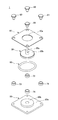
- FIG. 3 is an exploded view of the operation input device 1.
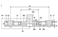
- FIG. 3 is a cross-sectional view of the operation input device 1.
- FIG. It is sectional drawing of the operation input apparatus 1 in the state which the yoke 30 slid. It is the perspective view which showed the state which the yoke 30 slid. It is the perspective view which showed the state which the yoke 30 slid.
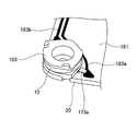
- 4 is an enlarged view of a part of an output unit 160.
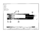
- FIG. It is a magnetic flux line vector figure in the yoke 30 origin position.
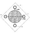
- FIG. 7 is a diagram showing a positional relationship between coils 71 to 74 and a yoke 30 to which no operation input is given.
- 11 is a graph showing a change in inductance of a coil 72 when the yoke 30 is stroked in the directions A and B shown in FIG. 10. It is the graph which showed the change of the inductance of the coil 72 when the yoke 30 is made to stroke in the direction A when the yoke 10 is a nonmagnetic material.
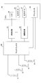
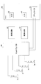
- 2 is a block diagram of a drive circuit 66 and a reception circuit 67.
- FIG. It is the figure which showed the waveform in each point of FIG.
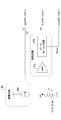
- 2 is a block diagram of a drive circuit 66 and a reception circuit 67.
- FIG. 3 is an exploded view of the operation input device 2.
- FIG. 3 is a cross-sectional view of the operation input device 2.
- FIG. It is sectional drawing of the operation input apparatus 2 in the state which the yoke 150 slid.
- 6 is a top view of the leaf spring 54.
- FIG. 3 is a side view of a leaf spring 54.
- FIG. 4 is a view showing coils 41 to 44 that elastically support a yoke 30.
- FIG. FIG. 6 is a view showing a state where a yoke 30 is slid in the X ( ⁇ ) direction. It is the figure which showed the state which the yoke 30 slid to the diagonal direction. It is the figure which showed the modification of the yoke 10 which has the Symposium
- FIG. It is sectional drawing of the operation input apparatus in the state which the yoke 30 of FIG. 37 slid.
- An operation input device is an operation interface that receives a force from an operator's finger or the like and outputs an output signal that changes in accordance with the received force.
- An operation input by the operator is detected based on the output signal. By detecting the operation input, it is possible to make the computer grasp the operation content corresponding to the detected operation input.
- a display object for example, a display provided on such an electronic device (for example, An instruction display such as a cursor or pointer, a character, or the like) can be moved according to the operation content intended by the operator.
- a desired function of the electronic device corresponding to the operation input can be exhibited.
- the inductance L of an inductor such as a coil (winding) usually has a coefficient K, permeability ⁇ , n number of coil turns, cross-sectional area S, and magnetic path length d.
- L K ⁇ n 2 S / d
- This operation input device receives an operator's force input from the Z-axis direction side of an orthogonal coordinate system determined by the X, Y, and Z axes.
- the Z axis direction refers to a direction parallel to the Z axis.
- the operation input detection device detects the movement of the member displaced by the operation input of the operator based on a signal from the operation input device (that is, based on a predetermined signal that changes according to the magnitude of the inductance). Thus, the operation input is detected.
- FIG. 1 is a perspective view of an operation input device 1 according to the first embodiment of the present invention.
- FIG. 2 is an exploded view of the operation input device 1.
- FIG. 3 is a cross-sectional view of the operation input device 1 in a 45 ° oblique direction with respect to the X axis and the Y axis.
- the operation input device 1 includes a first yoke, a second yoke, a third yoke, and a plurality of coils as components, and a magnetic circuit is formed by these components.
- the yoke 10 corresponds to a first yoke
- the yoke 20 corresponds to a second yoke
- the yoke 30 corresponds to a third yoke.
- the operation input device 1 includes four coils 71, 72, 73, 74 as a plurality of coils constituting the magnetic circuit.
- the yokes 10 and 20 are plate-shaped members.
- the yoke 30 and the coils 71 to 74 are disposed between the yoke 10 and the yoke 20 facing each other.
- the yoke 30 is a displacement member supported so as to be slidable in a direction parallel to the XY plane of an orthogonal coordinate system determined by the X, Y, and Z axes by applying an operation load as an operation input (see FIG. 4).
- the yoke 30 is supported by the yoke 10 and the yoke 20 so as to be movable in a direction parallel to the XY plane.
- the yoke 30 When the lower surface of the yoke 10 is in contact with the upper surface of the slide plate 30b of the yoke 30 and the upper surface of the yoke 20 is in contact with the lower surface of the slide plate 30b of the yoke 30, the yoke 30 is sandwiched between the yoke 10 and the yoke 20
- the yoke 30 can be supported so as to be displaceable in a direction parallel to the XY plane.
- the yoke 30 slides freely in each direction in the XY plane along the arrangement surface 20a on the upper surface of the yoke 20.
- the yoke 30 may slide freely in each direction in the XY plane along the slide surface 20b on the upper surface of the stepped step formed in the central portion of the arrangement surface 20a of the yoke 20.
- the arrangement surface 20 a and the slide surface 20 b are preferably flat in terms of reducing the height of the operation input device 1.
- the outer diameter of the slide surface 20b is substantially the same as the outer diameter of the circular slide plate 30b of the yoke 30, but one outer diameter may be larger than the other outer diameter.
- the yoke 30 By making the height of the slide surface 20b on which the yoke 30 slides in the Z direction (vertical direction in the case of FIGS. 3 and 4) higher than the arrangement surface 20a on which the coil spring 90 in contact with the yoke 30 is disposed, the yoke 30 The thickness of the slide plate 30b in the Z direction can be reduced. By reducing the thickness of the slide plate 30b in contact with the slide surface 20b, the yoke 30 can be reduced in weight.
- the height of the slide surface 20b is arranged so that the thickness center position of the slide plate 30b of the yoke 30 matches the height in the Z direction to the center of the coil spring 90 in which the wire is wound in a coil shape.
- the height is higher than the surface 20a.
- the yoke 30 is an operation unit having a protrusion 30a on which an operator's force can act.
- the yoke 30 is a displacement member that is displaced in the XY plane when the operator's force acts on the protrusion 30a.
- the yoke 30 is supported by the yoke 10 and the yoke 20 so as to be movable in a direction parallel to the XY plane.
- the position of the yoke 30 in the standby state (initial state) where the operator's force is not applied to the protrusion 30a is taken as the standby position (initial position). By acting, it supports so that it can move in the direction parallel to the XY plane from the standby position.
- the inner diameter of the through hole 10a of the yoke 10 is smaller than the outer diameter of the circular slide plate 30b of the yoke 30.
- the slide plate 30b of the yoke 30 can be sandwiched between the yoke 10 and the yoke 20 and supported so as to be displaceable in a direction parallel to the XY plane (see FIGS. 3 and 4). Further, foreign matter such as dust can be prevented from entering the operation input device 1.
- the protrusion 30a is formed on the slide plate 30b of the yoke 30 so that the protrusion 30a protrudes from the through hole 10a. This makes it easier for the operator to operate the yoke 30 in the sliding direction.
- the coils 71 to 74 are arranged in the circumferential direction of a virtual circle formed by connecting points having the same distance from the origin O, which is the reference point of the orthogonal coordinate system.
- the coils 71 to 74 are arranged at equal intervals in the circumferential direction in that the position of the reference point of the yoke 30 (for example, the center point of the slide plate 30b of the yoke 30) on the XY plane is easily detected. It is preferable.
- the coils 71 to 74 are arranged at 90 ° intervals in the circumferential direction in four directions of 45 ° obliquely in the XY plane sandwiched between the X axis and the Y axis.
- the coil 71 is arranged in the first quadrant
- the coil 72 is arranged in the second quadrant
- the coil 73 is arranged in the third quadrant
- the coil 74 is arranged in the fourth quadrant.
- the coils 71 to 74 may be arranged in four directions of X (+), X ( ⁇ ), Y (+), and Y ( ⁇ ) every 90 ° in the circumferential direction.
- the X ( ⁇ ) direction is 180 ° opposite to the X (+) direction on the XY plane
- the Y ( ⁇ ) direction is 180 ° opposite to the Y (+) direction on the XY plane.
- the coil 71 is disposed on the X axis on the positive side with respect to the origin O
- the coil 72 is disposed on the Y axis on the positive side with respect to the origin O
- the coil 73 is disposed on the negative side with respect to the origin O.
- the coil 74 is disposed on the X axis
- the coil 74 is disposed on the Y axis on the negative side with respect to the origin O.
- the yokes 10, 20, and 30 may be made of a material having a relative permeability higher than 1 in order to serve as a yoke.
- the relative magnetic permeability is preferably 1.001 or more, specifically, a steel plate (relative magnetic permeability 5000) or the like is preferable.
- Each core passing through each coil (that is, the cores 81 to 84) may or may not be resin, iron or ferrite.
- the coil spring 90 is an annular elastic member formed by connecting both ends of a coil portion in which a wire is wound in a coil shape.
- the outer periphery of the slide plate 30b of the yoke 30 is in elastic contact with the inner periphery of the coil spring 90 in the initial state where the yoke 30 is located at the origin O.
- the origin O corresponds to the initial position of the yoke 30 in the initial state where no operation input is given.
- the coil spring 90 returns the yoke 30 that has been slid as shown in FIGS. That is, when the operation input applied to the yoke 30 is released, the position of the yoke 30 returns to the initial position by the elastic force of the coil spring 90.
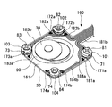
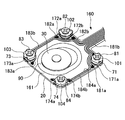
- FIG. 5 and 6 show an output unit 160 for outputting an output signal corresponding to the magnitude of the inductance of the coil to a predetermined operation input detection device.
- FIG. 7 is an enlarged view of a part of the output unit 160.
- the output unit 160 includes a terminal connected to the end of the coil so as to be energized, wiring connected to the terminal so as to be energized, and a film 161 provided with the wiring. Terminals and wiring are provided for each coil.
- the terminal 174a and the wiring 184a are connected to one upstream end of the coil 74 so as to be energized, and the terminals 174b and 184b are connected to the other downstream end of the coil 74 so as to be energized.
- the film 161 is arranged on the arrangement surface 20 a of the yoke 20.
- cylindrical members 101 to 104 are installed at the four corners of the rectangular yoke 20.
- the coils 71 to 74 are wound around the outer peripheral portions of the cylindrical members 101 to 104, respectively.
- the cores 81 to 84 are inserted into the inner peripheral portions of the cylindrical members 101 to 104, respectively.
- FIG. 8 and 9 are diagrams for explaining the principle of detection of the movement amount of the yoke 30.
- FIG. 8 is a magnetic flux line vector diagram in the region W1 in FIG. 3 in a state where the yoke 30 is located at the origin O.
- FIG. 9 is a magnetic flux line vector diagram in the region W2 of FIG. 4 in a state where the yoke 30 is slid.
- the coil inductance is determined by the average relative permeability of the surroundings when the coil specifications are constant.
- the average relative permeability around the coil is determined by the magnetic resistance determined by the magnetic path length of the magnetic circuit formed by the coils and yokes 10, 20, and 30.
- the predetermined operation input detection device can detect the yoke corresponding to the measured inductance according to the correspondence measured in advance. 30 slide amounts can be detected.
- the magnetic path of the magnetic circuit is formed in a square shape, so that the sliding amount of the yoke 30 and the inductance of the coil 73 are substantially proportional. There is a correlation. Therefore, according to the substantially proportional correlation, the sliding amount of the yoke 30 can be detected with higher accuracy based on the measured inductance.
- FIG. 10 is a diagram showing the positional relationship between the coils 71 to 74 and the yoke 30 to which no operation input is given.
- FIG. 11 is a graph showing a change in inductance of the coil 72 when the yoke 30 is stroked in the directions A and B shown in FIG.
- the stroke amount S represents the slide amount from the origin O of the yoke 30.
- the specifications of the coils 71 to 74 when measuring FIG. 11 are an inner diameter of 2.8 mm, an outer diameter of 3.6 mm, a height of 1.4 mm, a wire diameter of ⁇ 0.025 mm, a winding number of 480 turns, and a resistance value of 180 ⁇ .
- the materials of the yokes 10, 20, 30 and the cores 81 to 84 are ferritic stainless steel (SUS430). Also, the dimensions of the respective parts e1 to e6 shown in FIG. 3 are as follows: e1: thickness 0.4 mm, e2: thickness 0.6 mm, e3: ⁇ 10 mm, e4: 1.4 mm, e5: pitch 21.2 mm, e6 : The thickness is 0.8 mm. In addition, each specification, such as a dimension, is not this limitation.
- the magnitude of the inductance L of the coil 72 changes according to the sliding amount and sliding direction of the yoke 30 (that is, the position of the yoke 30).
- the coils 71, 73, 74 other than the coil 72 because they are symmetrical with respect to the X axis and the Y axis.
- the yokes 10, 20, and 30 all constitute detection means.
- the inductance does not change with respect to the sliding amount as shown in FIGS. That is, if the yoke is replaced with a nonmagnetic material, a loop magnetic circuit is not formed. Therefore, it is clear that the yoke 10 is a part constituting detection means for detecting the yoke 30 by converting the sliding amount of the yoke 30 into an inductance change amount.
- the yoke 20 is a part constituting detection means for detecting the yoke 30 by converting the sliding amount of the yoke 30 into an inductance change amount.
- the inductance detecting mechanism and the slide mechanism are arranged between the yokes together with the coil, and the inductance can be detected by the entire apparatus. Therefore, it is not necessary to provide a new mechanism for detecting the inductance. Therefore, a thin structure with a single-stage structure is possible without sacrificing the stroke in the circumferential direction more than necessary, and a low profile can be easily realized. In addition, since it can be constituted by a single-stage structure, it is robust against a load in the Z direction and has excellent breaking strength.
- the inductance detection mechanism and the slide mechanism are configured by the same component yoke 30, the component configuration for realizing the operation input device can be simplified. Further, since the position of the yoke 30 can be detected without contact by detecting the inductance, the wear resistance is excellent.
- a predetermined operation input detection device detects the inductance of each of the coils 71 to 74 by applying a current to each of the coils 71 to 74, and the magnitude of the inductance of each coil.
- the position of the yoke 30 with respect to the origin O is calculated based on the detection value representing
- the first calculation method of the position of the yoke 30 will be described with reference to FIGS.
- the coil 71 is disposed in the first quadrant
- the coil 72 is disposed in the second quadrant
- the coil 73 is disposed in the third quadrant
- the coil 74 is the fourth.
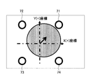
- the position of the yoke 30 is calculated according to the coordinate system arranged in the quadrant. On this coordinate system, the displacement of the yoke 30 in the positive Y direction is detected according to the sum of the inductances of the coil 71 and coil 72, and the displacement of the yoke 30 in the positive X direction is detected by the coil 71 and the coil 72.
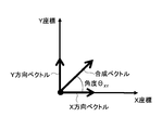
- the Y direction vector detected by the difference between the sum of the inductances of the coils 71 and 72 and the sum of the inductances of the coils 73 and 74 represents the displacement of the Y direction component of the yoke 30.
- the X-direction vector detected by the difference between the sum of the inductances of the coils 71 and 74 and the sum of the inductances of the coils 72 and 73 represents the displacement of the X-direction component of the yoke 30.
- the vector length of the combined vector of the X direction vector and the Y direction vector represents the sliding amount S of the yoke 30, and the vector angle of the combined vector with respect to the coordinate axis (for example, the X axis) represents the sliding direction ⁇ XY of the yoke 30. .
- the second calculation method uses the coordinate system shown in FIG. 19 as in the first calculation method.
- the first direction vector detected by the difference in inductance between the coil 72 and the coil 74 represents the displacement of the yoke 30 of the first linear direction component connecting the coil 72 and the coil 74, and the coil 71 and the coil 73.
- the second direction vector detected by the difference in inductance of the second represents the displacement of the yoke 30 of the second linear direction component connecting the coil 71 and the coil 73.
- the vector length of the combined vector of the first direction vector and the second direction vector represents the sliding amount S of the yoke 30, and the vector angle of the combined vector with respect to the coordinate axis (for example, the X axis) is the sliding direction of the yoke 30.
- ⁇ represents XY .
- the first and second calculation methods calculate the position of the yoke 30 according to the coordinate system shown in FIG.
- the coordinate system shown in FIG. 19 it is possible to detect the 360 ° direction in the XY plane, but the cross keys (X, Y) that are frequently operated on a mobile phone or a game machine. Since the sensitivity in the axial direction can be detected by the sum of two coils, the detection sensitivity can be increased. Therefore, when the device that receives the output of the operation input device uses only the XY directions, the sensitivity is doubled, and if the same sensitivity is designed, the size can be reduced.
- the amount of change in inductance of each coil relative to the amount of sliding of the yoke 30 may be corrected or normalized in advance. Thereby, calculation accuracy can be improved and calculation time can be shortened.
- the inductance of each of the four coils in the two states of the yoke 30 at the origin O (standby state) and the full stroke state is stored in the memory in advance.
- the inductance stored in the memory may be a value set in advance based on a design value, may be a value actually measured at the time of manufacture, or may be measured based on an instruction signal from the user when used by the user. Then, the maximum value of each inductance in use may be learned.
- the detected value of the inductance changes between the minimum value in the standby state and the maximum value in the full stroke state obtained by such a method.
- the inductance of each coil may be evaluated, or the difference in inductance between a pair of opposing coils may be evaluated.
- the amount of change in inductance of each coil with respect to the sliding amount of the yoke 30 is corrected or normalized.
- the vector length of the combined vector corresponds to the slide amount
- the vector angle ⁇ XY corresponds to the slide direction
- FIG. 22 is a block diagram of a first detection circuit example for detecting a change in inductance.
- the inductance detection circuit is calculation means for detecting a change in inductance of each of the coils 71 to 74.
- the inductance detection circuit includes a CPU 60 which is a calculation means, a drive circuit 66 connected to the first output port 61 of the CPU 60, and the other ends of the coils 71 to 74 whose one end is connected to the ground.
- a multiplexer (MUX) 68 to be connected and a receiving circuit 67 connected to the second output port 62 and the AD port 63 of the CPU 60 are provided.
- MUX multiplexer
- Each coil sandwiched between the yoke 10 and the yoke 20 is connected to the CPU 60 by the multiplexer 68 via the common receiving circuit 67 and driving circuit 66. Switching of the connection destination of the multiplexer 68 is uniquely selected by address designation from the CPU 60 via the address bus 64. Therefore, the detection of the inductance of each coil is sequentially performed for each coil by shifting the detection timing of each coil.
- FIG. 23 is a block diagram of the driving circuit 66 and the receiving circuit 67 in FIG.
- the drive circuit 66 controls the output current of the constant current source 66a in accordance with the output signal from the output port 61 of the CPU 60, thereby causing a current to flow through each of the coils 71 to 74.
- the receiving circuit 67 inputs a voltage generated when a current flows through the coil 21 or the like to the peak hold circuit 67b through the amplifier 67a (may be input to the bottom hold circuit).
- the peak value (analog value) peak-held by the peak hold circuit 67b is input to the AD port 63 and converted into a digital value by the AD converter.
- FIG. 24 is a diagram showing waveforms at each point in FIG.
- a rectangular wave voltage waveform is output from the output port 61 of the CPU 60.
- the constant current circuit 66a allows a constant current to flow through the coil.
- the coil generates a voltage V2 having a differential waveform.
- As the voltage waveform V2 a waveform 2-1 synchronized with the rising of the voltage waveform V1 is obtained, and a waveform 2-2 synchronized with the falling of the voltage waveform V1 is obtained.
- the waveform 2-2 is a waveform having positive and negative sides opposite to the waveform 2-1.
- the amplifier 67a amplifies the voltage waveform V2 to a size suitable for the dynamic range of the AD converter.
- the held value is taken into the AD converter (AD port 63). Since the amplitude values of the waveforms 2-1 and 2-2 increase in proportion to the magnitude of the inductance of each coil, the magnitude of the inductance of each coil can be evaluated by detecting this amplitude value.
- FIG. 25 is a block diagram of a second detection circuit example for detecting a change in inductance.
- the inductance detection circuit is calculation means for detecting a change in inductance of each of the coils 71 to 74.
- the inductance detection circuit is connected to the CPU 60 which is a calculation means, the drive circuit 66 connected to the DA port 65 of the CPU 60, and the other ends of the coils 71 to 74 whose one end is connected to the ground.
- a multiplexer (MUX) 68 and a receiving circuit 67 connected to the AD port 63 are provided.
- Each coil sandwiched between the yoke 10 and the yoke 20 is connected to the CPU 60 by the multiplexer 68 via the common receiving circuit 67 and driving circuit 66. Switching of the connection destination of the multiplexer 68 is uniquely selected by address designation from the CPU 60 via the address bus 64. Therefore, the detection of the inductance of each coil is sequentially performed for each coil by shifting the detection timing of each coil.
- FIG. 26 is a block diagram of the driving circuit 66 and the receiving circuit 67 in FIG.
- the drive circuit 66 controls the output current of the constant current source 66a in accordance with the output signal from the DA port 65 of the CPU 60, thereby causing a current to flow through each of the coils 71 to 74.
- the receiving circuit 67 inputs a voltage generated when a current flows through the coil 21 and the like to the AD port 63 through the amplifier 67a.
- the analog value input to the AD port 63 is converted into a digital value by the AD converter.
- FIG. 27 is a diagram showing waveforms at each point in FIG.
- a triangular voltage waveform is output from the DA port 66 of the CPU 60.
- the triangular wave has a constant rising slope (that is, the rising edge is a straight line). In this example, both the rising and falling slopes are the same.
- the constant current circuit 66a passes a current I1 that increases as the voltage V1 increases and decreases as the voltage V1 decreases.
- the coil generates a voltage indicated by V2, which is a derivative of the waveform indicated by the current I2. Since the waveform of V2 increases and decreases in a straight line, the waveform of V2 becomes a rectangular wave with a constant voltage section as indicated by V2.
- the output waveform V2 As the output waveform V2, a voltage such as 2-1 corresponding to the rising edge of the triangular wave is obtained, and a voltage such as 2-2 corresponding to the falling edge of the triangular wave is obtained.
- the waveform 2-2 is a waveform having positive and negative sides opposite to the waveform 2-1.
- the amplifier 67a amplifies the voltage waveform V2 to a size suitable for the dynamic range of the AD converter.
- the AD converter captures the amplitude value of the voltage waveform V3 during a period in which the voltage waveform V3 is constant at a synchronization timing based on the drive output timing. Since the amplitude values of the waveforms 3-1 and 3-2 increase in proportion to the magnitude of the inductance of each coil, the magnitude of the inductance of each coil can be evaluated by detecting this amplitude value.
- a voltage V2 having a slope is generated in the constant voltage section of the voltage V2 shown in FIG.
- the voltage V2 having this slope may be held using a sample hold circuit at a synchronization timing based on the drive output timing, and the held value may be captured by an AD converter.
- the values obtained by taking in the respective periods of the waveforms 3-1 and 3-2 by the AD converter and adding or averaging the absolute values of the taken values may be used for evaluating the magnitude of the inductance.
- FIG. 28 is a perspective view of the operation input device 2 according to the second embodiment of the present invention.
- FIG. 29 is an exploded view of the operation input device 2.
- FIG. 30 is a cross-sectional view of the operation input device 2 in an oblique 45 ° direction with respect to the X axis and the Y axis. The description of the same parts as those in the above embodiment is omitted.
- the operation input device 2 is composed of a magnetic circuit using a yoke, and includes a first yoke 130, a second yoke 140, and a third yoke 150.
- the first yoke 130 is disposed on the upper side of the third yoke 150
- the second yoke 140 is disposed on the lower side of the third yoke 150.
- the protrusion 55 is pressed with an initial load by the elastic force of the leaf spring 54.
- the second yoke 140 has an arrangement surface 140b on which the third yoke 150 is arranged.
- the third yoke 150 slides freely in each direction along the arrangement surface 140b.
- a hole 140 a through which the leaf spring 54 passes is formed at the center of the second yoke 140.
- the inner diameter of the circular hole 140 a is smaller than the outer diameter of the circular slide plate of the third yoke 150.
- the third yoke 150 is supported by the second yoke 140 and the first yoke 130 so as to be movable in a direction parallel to the XY plane.
- the lower surface of the first yoke 130 is in contact with the upper surface of the slide plate of the third yoke 150, and the arrangement surface 140b of the second yoke 140 is in contact with the lower surface of the slide plate of the third yoke 150.
- 150 can be sandwiched between the second yoke 140 and the first yoke 130 so as to be displaceable in a direction parallel to the XY plane.
- the protrusion 150 a provided on the third yoke 150 passes through a hole 130 a formed in the center of the first yoke 130 and is exposed from the upper surface of the first yoke 130.
- the inner diameter of the circular hole 130 a is smaller than the outer diameter of the circular slide plate of the third yoke 150.
- a plurality of coils are arranged in the circumferential direction between the first yoke 130 and the second yoke 140 facing each other in the Z direction.
- the four coils 111 to 114 are arranged outside the slide plate of the third yoke 150 at equal intervals in the circumferential direction.
- the coils 111 to 114 are arranged in a circumferential direction of a virtual circle formed by connecting points having the same distance from the origin O.
- the coils 111 to 114 are preferably arranged at equal intervals in the circumferential direction from the viewpoint of easy calculation of the operator's force vector. When each coil has the same characteristic, the distance between the centers of gravity of two adjacent coils may be equal.
- the third yoke 150 is disposed on the Z axis passing through the origin O.
- a recess 31 having a substantially conical side surface is formed on the lower surface of the third yoke 150.
- the first yoke 130, the second yoke 140, and the third yoke 150 literally function as a yoke. Therefore, the first yoke 130, the second yoke 140, and the third yoke 150 may be made of a material having a relative permeability higher than 1.
- the relative magnetic permeability is preferably 1.001 or more, specifically, a steel plate (relative magnetic permeability 5000) or the like is preferable.
- Each of the cores that penetrate each coil (that is, the cores 121 to 124) may or may not be resin, iron, or ferrite.
- the predetermined operation input detection device can detect the yoke corresponding to the measured inductance according to the correspondence measured in advance. 150 slide amounts can be detected.
- the magnetic path length of the magnetic circuit linearly decreases with an increase in the sliding amount of the third yoke 150. Therefore, since the amount of change in inductance increases linearly with respect to the sliding amount of the third yoke 150, the sliding position can be detected with a certain accuracy regardless of the position of the third yoke 150.
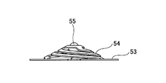
- FIG. 32 is a top view of the leaf spring 54 having a spiral shape.
- FIG. 33 is a side view of the leaf spring 54.
- the leaf spring 54 has a helical shape and has a conical shape so that stress can be efficiently relieved in the recess 31 of the third yoke 150 and the stroke can be maximized in the Z direction.
- the leaf spring 54 is an elastic member disposed below the third yoke 150.
- the protrusion 55 is a spherical member (typically a sphere) that abuts against the concave surface 31 b of the concave portion 31 formed on the lower surface of the third yoke 150 by the urging force of the leaf spring 54.
- the leaf spring 54 is spirally extended from the bottom surface of the cone shape toward the vertex so as to form a substantially cone-shaped side surface with the position of the protrusion 55 as the vertex.
- the projection 55 is pressed against the concave apex 31a of the third yoke 150 with an initial load due to the elastic force of the leaf spring 54, whereby the third yoke 150 is held at the initial position.
- the leaf spring 54 bends in a direction perpendicular to the sliding direction of the third yoke 150 by the action of the concave surface 31b.
- An origin return mechanism for returning the third yoke 150 to the initial position (origin) using the return force generated by the bending is realized.
- the spring is not disposed in the sliding direction in which the third yoke 150 can slide, and the bending direction of the leaf spring 54 with respect to the sliding operation of the third yoke 150 ( Since the contraction direction) is vertical, the slide amount of the third yoke 150 is hardly limited by the presence of the leaf spring 54, and the third yoke 150 can be made to have a long stroke.
- the leaf spring 54 that receives a force from the concave surface 31 b via the protrusion 55 is in the normal direction downward with respect to the XY plane. Shrink to. Therefore, since the contraction direction of the leaf spring 54 is perpendicular to the sliding direction of the third yoke 150, it is possible to easily and largely secure a sliding amount by which the third yoke 150 can slide.
- the leaf spring 54 has a substantially cone-shaped spiral structure from the bottom surface to the apex, when the downward force is received, the apex moves downward in the center surrounded by the spiral. Compared with a cylindrical coil spring, the height from the bottom surface to the apex can be reduced. Further, since the leaf spring 54 has a spirally bent shape, the degree of freedom in spring design is improved, so that a wider range of deformation and restoring force can be imparted to the spring. Moreover, since the spring length becomes long and the stress which arises in a spring can be reduced by making it helical, durability improves.
- the third yoke 150 slides through the projection 55. Can reduce friction.
- the protrusion 55 is a sphere, it is in rolling contact, so that the frictional resistance can be further reduced. As a result, wear resistance is improved and heat generation can be suppressed.
- the degree of freedom in selecting the material of the third yoke 150 and the leaf spring 54 is increased. Increase.
- each of the coil springs 41 to 44 is an elastic member having both ends as fixed ends. Both ends of each coil spring are fixed by convex mounting portions (bosses) formed on the arrangement surface 20a of the yoke 20 so that each coil spring contacts the outer periphery of the slide plate 30b of the yoke 30 with different contacts. (See FIGS. 35 and 36).
- one fixed end 41a of the coil spring 41 is fixed by the mounting portion 11a, and the other fixed end 41b is fixed by the mounting portion 11b.
- Coil portions 41c to 44c having a length equal to or longer than a predetermined value are formed by winding a wire rod in a coil shape at an intermediate portion sandwiched between fixed ends on both sides of each coil spring.
- FIG. 35 is a view showing a state in which the yoke 30 is slid in the X ( ⁇ ) direction.
- FIG. 36 is a view showing a state where the yoke 30 is slid in an oblique direction.
- the coil springs 41 to 44 are arranged in a circumferential direction of a virtual circle formed by connecting points having the same distance from the origin O, which is the reference point of the orthogonal coordinate system.
- the coil springs 41 to 44 are arranged at equal intervals in the circumferential direction in order to make it easier to detect the positions of the reference points of the yoke 30 (for example, the center point and the center of gravity of the yoke 30) on the XY plane. It is preferable.
- the coil springs 41 to 44 are arranged in contact with the outside of the outer peripheral edge of the yoke 30, and the X (+) direction that is the X axis positive side direction, the X ( ⁇ ) direction that is the X axis negative side direction, The Y (+) direction, which is the Y axis positive side direction, and the Y ( ⁇ ) direction, which is the Y axis negative side direction, are arranged every 90 ° in the circumferential direction outside the slide plate 30b of the yoke 30. .
- the coil spring 41 is disposed on the X axis on the positive side with respect to the origin O
- the coil spring 42 is disposed on the Y axis on the positive side with respect to the origin O
- the coil spring 43 is disposed on the origin O.
- the coil spring 44 is disposed on the negative X-axis
- the coil spring 44 is disposed on the negative Y-axis with respect to the origin O.
- the origin O corresponds to the initial position of the yoke 30 in the initial state where no operation load is received. When the operation load applied to the yoke 30 is released, the position of the yoke 30 returns to the initial position by the action of the elastic force of the coil spring arranged in contact with the outer periphery of the yoke 30.
- each coil spring is deflected by a lateral load and elastically deformed (ie, X (+), X ( ⁇ ), Y (+), Y ( ⁇ )).
- the two coil springs are deflected by the lateral load and elastically deformed (ie, obliquely sandwiched between the X axis and the Y axis) Since the operation load necessary to slide the yoke 30 in four directions (45 °) is large, the feeling when operating in the four directions of the XY axes and the feeling when operating in the four oblique directions sandwiched between these directions And can be changed.
- the arrangement position of the coil spring may be shifted by 45 ° in the circumferential direction.
- the elastic coefficients of the coil springs are the same, but may be different.
- the elastic coefficient of one coil spring is the same as the elastic coefficient of the coil spring disposed at a position facing the one coil spring across the yoke 30 and is adjacent to the one coil spring in the circumferential direction. Different from the elastic coefficient of the coil spring.
- the coil springs 41 and 43 facing each other across the yoke 30 have the same elastic coefficient, and the coil springs 42 and 44 facing each other in the other direction across the yoke 30
- the elastic modulus is different from the modulus.
- size of an operation load can be freely changed according to an operation direction by changing the arrangement position and elastic coefficient in the circumferential direction of each coil spring. Even if the outer peripheral shape of the slide plate 30b of the yoke 30 is changed (for example, it is not limited to a circle but a polygon), the magnitude of the operation load can be freely changed according to the operation direction.
- each of the coil portions 41c to 44c in an initial state where no operation input is received, each of the coil portions 41c to 44c is in an urging state in which the yoke 30 can be held at the initial position in the initial state with different contacts. And is in contact with the outer periphery of the slide plate 30b of the yoke 30. As a result, the yoke 30 can be prevented from starting to slide from the initial position unless an operation load of a certain value or more is applied to the yoke 30.
- FIGS. 37 and 38 show the configuration in which the yoke 30 slides along the slide surface 20b of the stepped step of the yoke 20, but as shown in FIGS. 37 and 38, the outer ring of the hole 10a of the yoke 10 is shown. You may provide the protrusion along. By this projection, the yoke 10 is supported so as to be freely slidable in each direction in the XY plane. In the case of this configuration, a magnetic circuit passing through this protrusion is formed.
- the embodiment using four coils has been exemplified.
- the position of the yoke in the XY plane can be detected. it can.
- the initial position of the yoke that can slide along the XY plane is the origin O
- one coil may be arranged on the X axis and the other coil may be arranged on the Y axis.
- one coil may be used to detect the position of the yoke in one axial direction.
- one coil may be disposed on the axis of the yoke in the sliding direction.
- the operation input device is not limited to fingers and may be operated with the palm of the hand. Moreover, you may operate with a toe or a sole.
- the surface touched by the operator may be a flat surface, a concave surface, or a convex surface.
Landscapes
- Engineering & Computer Science (AREA)
- General Engineering & Computer Science (AREA)
- Theoretical Computer Science (AREA)
- Human Computer Interaction (AREA)
- Physics & Mathematics (AREA)
- General Physics & Mathematics (AREA)
- Switches With Compound Operations (AREA)
- Position Input By Displaying (AREA)
- Switches That Are Operated By Magnetic Or Electric Fields (AREA)
Abstract
操作入力装置は、第1のヨークと、第2のヨークと、第1のヨークと第2のヨークとの間に配置されたコイルと、第1のヨークと第2のヨークとの間に配置され、前記コイルのインダクタンスを変化させる第3のヨークと、前記インダクタンスの大きさに応じた出力信号を出力する出力部とを含み、前記コイルに対して第3のヨークが操作入力により変位することで、第1のヨークと第2のヨークと第3のヨークと前記コイルから形成された磁気回路の磁路長が変化することによって、前記インダクタンスが変化する。
Description
本発明は、操作入力を受ける操作入力装置、及び操作入力を検出する操作入力検出装置に関する。
従来、スライド操作可能な可動部材が上段のカバーに配設され、その可動部材のスライド方向及びスライド量を検出可能な検出部材が下段のカバーに配設された、座標入力装置が知られている(例えば、特許文献1の図3を参照)。
しかしながら、上述の従来技術では、可動部材と検出部材が上下2段で構成されるため、低背構造を実現することが難しい。
そこで、本発明は、低背化を容易に実現できる、操作入力装置及び操作入力検出装置の提供を目的とする。
上記目的を達成するため、本発明に係る操作入力装置は、
第1のヨークと、
第2のヨークと、
第1のヨークと第2のヨークとの間に配置されたコイルと、
第1のヨークと第2のヨークとの間に配置され、前記コイルのインダクタンスを変化させる第3のヨークと、
前記インダクタンスの大きさに応じた出力信号を出力する出力部とを備え、
前記コイルに対して第3のヨークが操作入力により変位することで、第1のヨークと第2のヨークと第3のヨークと前記コイルから形成された磁気回路の磁路長が変化することによって、前記インダクタンスが変化することを特徴とするものである。
第1のヨークと、
第2のヨークと、
第1のヨークと第2のヨークとの間に配置されたコイルと、
第1のヨークと第2のヨークとの間に配置され、前記コイルのインダクタンスを変化させる第3のヨークと、
前記インダクタンスの大きさに応じた出力信号を出力する出力部とを備え、
前記コイルに対して第3のヨークが操作入力により変位することで、第1のヨークと第2のヨークと第3のヨークと前記コイルから形成された磁気回路の磁路長が変化することによって、前記インダクタンスが変化することを特徴とするものである。
本発明によれば、低背化を容易に実現できる。
本発明の他の目的、特徴及び利点は添付の図面を参照し以下の詳細な説明を読むことにより、一層明瞭となるであろう。
本発明の第1の実施形態である操作入力装置1の斜視図である。
操作入力装置1の分解図である。
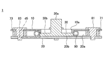
操作入力装置1の断面図である。
ヨーク30がスライドした状態での操作入力装置1の断面図である。
ヨーク30がスライドした状態を示した斜視図である。
ヨーク30がスライドした状態を示した斜視図である。
出力部160の一部の拡大図である。
ヨーク30が原点位置での磁束線ベクトル図である。
ヨーク30がスライドした状態での磁束線ベクトル図である。
コイル71~74と操作入力が付与されていないヨーク30との位置関係を示した図である。
ヨーク30を図10に示した方向A,Bへストロークさせたときのコイル72のインダクタンスの変化を示したグラフである。
ヨーク10が非磁性体のときの、ヨーク30を方向Aにストロークさせたときのコイル72のインダクタンスの変化を示したグラフである。
ヨーク10が非磁性体のときの、ヨーク30が原点位置での磁束線ベクトル図である。
ヨーク10が非磁性体のときの、ヨーク30が方向Aにストロークした状態での磁束線ベクトル図である。
ヨーク20が非磁性体のときの、ヨーク30を方向Aにストロークさせたときのコイル72のインダクタンスの変化を示したグラフである。
ヨーク20が非磁性体のときの、ヨーク30が原点位置での磁束線ベクトル図である。
ヨーク20が非磁性体のときの、ヨーク30が方向Aにストロークした状態での磁束線ベクトル図である。
XY平面におけるベクトル図である。
各象限内にコイルが設置されたときの配置図である。
XY平面におけるベクトル図である。
XY軸上にコイルが設置されたときの配置図である。
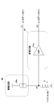
インダクタンスの変化を検出する第1の検出回路例のブロック図である。
駆動回路66と受信回路67のブロック図である。
図23の各点における波形を示した図である。
インダクタンスの変化を検出する第2の検出回路例のブロック図である。
駆動回路66と受信回路67のブロック図である。
図26の各点における波形を示した図である。
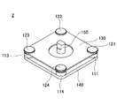
本発明の第2の実施形態である操作入力装置2の斜視図である。
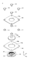
操作入力装置2の分解図である。
操作入力装置2の断面図である。
ヨーク150がスライドした状態での操作入力装置2の断面図である。
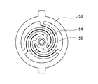
板ばね54の上面視図である。
板ばね54の側面図である。
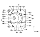
ヨーク30を弾性的に支持するコイル41~44を示した図である。
ヨーク30がX(-)方向にスライドした状態を示した図である。
ヨーク30が斜め方向にスライドした状態を示した図である。
ヨーク30を支持する突起を有するヨーク10の変形例を示した図である。
図37のヨーク30がスライドした状態での操作入力装置の断面図である。
以下、図面を参照しながら、本発明を実施するための形態の説明を行う。本発明の一実施形態である操作入力装置は、操作者の手指等による力を受けて、その受けた力に応じて変化する出力信号を出力する操作インターフェイスである。その出力信号に基づいて操作者による操作入力が検出される。操作入力の検出によって、その検出された操作入力に対応する操作内容をコンピュータに把握させることができる。
例えば、家庭用又は携帯可能なゲーム機、携帯電話や音楽プレーヤーなどの携帯端末、パーソナルコンピュータ、電化製品などの電子機器において、そのような電子機器に備えられるディスプレイの画面上の表示物(例えば、カーソルやポインタなどの指示表示や、キャラクターなど)を、操作者が意図した操作内容に従って、移動させることができる。また、操作者が所定の操作入力を与えることにより、その操作入力に対応する電子機器の所望の機能を発揮させることができる。
一方、通常、コイル(巻線)等のインダクタのインダクタンスLは、係数をK、透磁率をμ、コイルの巻数をn、断面積をS、磁路長をdとした場合、
L=Kμn2S/d
という関係式が成り立つ。この関係式から明らかなように、コイルの巻数や断面積といった形状に依存するパラメータを固定した場合、周囲の透磁率と磁路長の少なくともいずれかを変化させるかによって、インダクタンスが変化する。
L=Kμn2S/d
という関係式が成り立つ。この関係式から明らかなように、コイルの巻数や断面積といった形状に依存するパラメータを固定した場合、周囲の透磁率と磁路長の少なくともいずれかを変化させるかによって、インダクタンスが変化する。
このインダクタンスの変化を利用する操作入力装置及び操作入力検出装置の実施例について以下説明する。この操作入力装置は、X,Y,Z軸によって定まる直交座標系のZ軸方向側から入力される操作者の力を受け付けるものである。Z軸方向とは、Z軸に平行な方向のことをいう。操作入力検出装置は、操作入力装置からの信号に基づいて(すなわち、インダクタンスの大きさに応じて変化する所定の信号に基づいて)、操作者の操作入力により変位する部材の動きを検知することにより、その操作入力を検出するものである。
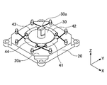
図1は、本発明の第1の実施形態である操作入力装置1の斜視図である。図2は、操作入力装置1の分解図である。図3は、X軸及びY軸に対して斜め45°方向での操作入力装置1の断面図である。
操作入力装置1は、第1のヨークと、第2のヨークと、第3のヨークと、複数のコイルとを構成要素として備え、これらの構成要素によって磁気回路が形成されている。図1において、ヨーク10が第1のヨークに相当し、ヨーク20が第2のヨークに相当し、ヨーク30が第3のヨークに相当する。また、操作入力装置1は、磁気回路を構成する複数のコイルとして、4個のコイル71,72,73,74を備える。ヨーク10,20は、板状の部材である。ヨーク30及びコイル71~74は、互いに対向するヨーク10とヨーク20との間に配置されている。
ヨーク30は、操作荷重を操作入力として加えることにより、X,Y,Z軸によって定まる直交座標系のXY平面に平行な方向にスライド可能に支持された変位部材である(図4参照)。ヨーク30は、ヨーク10とヨーク20によってXY平面に平行な方向に移動可能に支持されている。ヨーク30のスライド板30bの上面にヨーク10の下面が接し、ヨーク30のスライド板30bの下面にヨーク20の上面が接することによって、ヨーク10とヨーク20との間にヨーク30を挟んだ状態で、XY平面に平行な方向に変位可能にヨーク30を支持することができる。
ヨーク30は、ヨーク20の上面の配置面20aに沿ってXY平面内の各方向に自在にスライドする。ヨーク30は、ヨーク20の配置面20aの中央部に形成された台状段差の上面のスライド面20bに沿ってXY平面内の各方向に自在にスライドしてもよい。配置面20aとスライド面20bは、操作入力装置1の低背化の点で、平面であることが好ましい。スライド面20bの外径は、ヨーク30の円形状のスライド板30bの外径と略同一であるが、一方の外径が他方の外径よりも大きくてもよい。
ヨーク30がスライドするスライド面20bのZ方向(図3,4の場合、上下方向)の高さを、ヨーク30に接するコイルスプリング90が配置される配置面20aよりも高くすることによって、ヨーク30のスライド板30bのZ方向の肉厚を薄くできる。スライド面20bに接するスライド板30bの肉厚が薄くなることによって、ヨーク30を軽量化できる。また、線材をコイル状に巻き回したコイルスプリング90の中心部までのZ方向の高さに、ヨーク30のスライド板30bの肉厚中心位置が一致するように、スライド面20bの高さを配置面20aよりも高くすると好適である。コイルスプリング90の中心高さとヨーク30のスライド板30bの肉厚中心位置を一致させることによって、ヨーク30のスライド板30bの外周にコイルスプリング90の側部を安定して当接させることができる。
ヨーク30は、操作者の力が作用しうる突起部30aを有する操作部である。ヨーク30は、操作者の力が突起部30aに作用することにより、XY平面内を変位する変位部材である。ヨーク30は、ヨーク10とヨーク20によってXY平面に平行な方向に移動可能に支持されている。操作者の力が突起部30aに作用されていない待機状態(初期状態)でのヨーク30の位置を待機位置(初期位置)として、ヨーク10とヨーク20は、操作者の力が突起部30aに作用することによって、その待機位置からXY平面に平行な方向に移動できるように支持する。
ヨーク10の貫通孔10aの内径は、ヨーク30の円形のスライド板30bの外径に比べて小さい。これによって、ヨーク30のスライド板30bを、ヨーク10とヨーク20との間に挟んで、XY平面に平行な方向に変位可能に支持することができる(図3,4参照)。また、ほこりなどの異物が操作入力装置1の内部に入ることを防止することができる。突起部30aが貫通孔10aから突出するように、突起部30aがヨーク30のスライド板30bに形成されている。これによって、操作者がヨーク30をスライド方向に操作しやすくなる。
コイル71~74は、直交座標系の基準点である原点Oとの距離が等しい点を結んでできる仮想的な円の円周方向に並べられている。コイル71~74は、ヨーク30の基準点(例えば、ヨーク30のスライド板30bの中心点)のXY平面上の位置を検知しやすくするという点で、その円周方向に等間隔に配置されることが好ましい。コイル71~74は、X軸とY軸に挟まれるXY平面内の斜め45°の4方向に、その円周方向に90°毎に配置されている。コイル71は第1象限に配置され、コイル72は第2象限に配置され、コイル73は第3象限に配置され、コイル74は第4象限に配置される。
なお、コイル71~74は、X(+),X(-),Y(+),Y(-)の4方向に、その円周方向に90°毎に配置されていてもよい。X(-)方向は、XY平面上でX(+)方向に対して180°反対向きの方向であり、Y(-)方向は、XY平面上でY(+)方向に対して180°反対向きの方向である。コイル71は、原点Oに対して正側のX軸上に配置され、コイル72は、原点Oに対して正側のY軸上に配置され、コイル73は、原点Oに対して負側のX軸上に配置され、コイル74は、原点Oに対して負側のY軸上に配置されている。
ヨーク10,20,30は、ヨークの役目を果たすため、比透磁率が1よりも高い材質であればよい。例えば、比透磁率は1.001以上あると好適であり、具体的には、鋼板(比透磁率5000)などが好ましい。各コイルを貫くコアそれぞれは(すなわち、コア81~84は)、樹脂でも鉄でもフェライトでもよく、無くてもよい。
コイルスプリング90は、線材がコイル状に巻かれたコイル部の両端同士が接続されることにより形成される環状の弾性部材である。ヨーク30のスライド板30bの外周が、ヨーク30が原点Oに位置している初期状態で、コイルスプリング90の内周に弾性的に付勢されて接している。原点Oは、操作入力が付与されていない初期状態におけるヨーク30の初期位置に相当する。
コイルスプリング90は、操作入力の付与により図5,6のようにスライドしたヨーク30を、原点復帰させる。すなわち、ヨーク30に付与する操作入力を解除すると、コイルスプリング90の弾性力によって、ヨーク30の位置は初期位置に戻る。
図5,6には、コイルのインダクタンスの大きさに応じた出力信号を所定の操作入力検知装置に出力するための出力部160が示されている。図7は、出力部160の一部分の拡大図である。出力部160は、コイルの端部に通電可能に接続される端子と、該端子に通電可能に接続される配線と、該配線が設けられたフィルム161とを備える。端子及び配線は、コイル毎に設けられる。例えば、端子174a及び配線184aがコイル74の一方の上流側の端部に通電可能に接続され、端子174b及び184bがコイル74のもう一方の下流側の端部に通電可能に接続される。他のコイルについても同様である。フィルム161は、ヨーク20の配置面20aに配置される。
また、方形状のヨーク20の四隅には、筒状部材101~104が設置されている。コイル71~74は、それぞれ、筒状部材101~104の外周部に巻かれる。コア81~84は、それぞれ、筒状部材101~104の内周部に挿入される。雄ネジ形状を有するコアを採用することによって、各コイルのインダクタンスの絶対値を上げつつ、ヨーク30及びコイル71~74を挟んだ状態で、ヨーク10とヨーク20を締結することができる。
図8,9は、ヨーク30の移動量の検出原理を説明するための図である。図8は、ヨーク30が原点Oに位置した状態における図3の領域W1内の磁束線ベクトル図である。図9は、ヨーク30がスライドした状態における図4の領域W2内の磁束線ベクトル図である。コイルのインダクタンスを計測するため、所定の操作入力検知装置がコイルに電流を印加すると、その電流により、磁界が発生する。発生した磁界(磁束)は、コイル、ヨーク10、ヨーク30、ヨーク20により形成されている磁気回路中をループする。コイルのインダクタンスは、コイルの仕様が一定である場合、周囲の平均の比透磁率により決定される。コイル及びヨーク10,20,30によって形成される磁気回路の磁路長によって定まる磁気抵抗によって、コイル周辺の平均の比透磁率が決まる。
XY平面において360°方向に可動するヨーク30が、原点位置の状態(図8)に対して、外周に配置したコイル73に近づく方向に操作入力によってスライドすると(図9)、ヨーク30とヨーク10との上下方向での重複部分の端部(すなわち、ヨーク30のスライド板30bの外周端)がコイル73に近づくため、図示の通り、磁気回路のループ状の磁路長がd1からd2に短くなる。ヨーク30がコイル73に近づくことにより磁路長が短くなることによって、コイル73のインダクタンスが増加する方向に変化する。したがって、ヨーク30のスライド量とコイル73のインダクタンスとの対応関係を予め測定しておくことによって、所定の操作入力検知装置は、予め測定されたその対応関係に従って、計測されたインダクタンスに対応するヨーク30のスライド量を検知できる。
特に、図8,9に示した構成の場合、磁気回路を断面で見ると、その磁気回路の磁路が方形状に形成されているため、ヨーク30のスライド量とコイル73のインダクタンスは略比例の相関関係を有している。したがって、その略比例の相関関係に従えば、計測されたインダクタンスに基づいて、ヨーク30のスライド量を更に精度良く検知できる。
図10は、コイル71~74と操作入力が付与されていないヨーク30との位置関係を示した図である。図11は、ヨーク30を図10に示した方向A,Bへストロークさせたときのコイル72のインダクタンスの変化を示したグラフである。ストローク量Sは、ヨーク30の原点Oからのスライド量を表す。図11を計測したときのコイル71~74の仕様は、内径2.8mm×外径3.6mm×高さ1,4mm、線径φ0.025mm、巻数480回、抵抗値180Ωである。また、ヨーク10,20,30及びコア81~84の材質は、フェライト系ステンレス(SUS430)である。また、図3に示したe1~e6の各部の寸法は、e1:厚さ0.4mm、e2:厚さ0.6mm、e3:φ10mm、e4:1.4mm、e5:ピッチ21.2mm、e6:厚さ0.8mmである。なお、寸法等の各仕様は、この限りでない。
したがって、図11から明らかなように、コイル72のインダクタンスLの大きさは、ヨーク30のスライド量及びスライド方向(すなわち、ヨーク30の位置)に応じて、変化していることがわかる。コイル72以外の他のコイル71,73,74についても、X軸,Y軸に対して対称であるから、同様のことが言える。このような特性を利用することで、各コイルのインダクタンスLの大きさを計測することによって、ヨーク30の位置を容易に推定することができる。
ここで、ヨーク10,20,30が全て検出手段を構成していることを証明する。ヨーク10を比透磁率が1の非磁性体に置き換えて、ヨーク30を方向Aに移動させた場合、図12~図14に示されるように、スライド量に対するインダクタンスの変化は発生しない。つまり、ヨークを非磁性体に置き換えると、ループの磁気回路が形成されないためである。したがって、ヨーク10が、ヨーク30のスライド量をインダクタンスの変化量に変換して検出する検出手段を構成する一部分であることは明確である。同様に、ヨーク20を比透磁率が1の非磁性体に置き換えて、ヨーク30を方向Aに移動させた場合、図15~17に示されるように、スライド量に対するインダクタンスの変化は発生しない。したがって、ヨーク20が、ヨーク30のスライド量をインダクタンスの変化量に変換して検出する検出手段を構成する一部分であることは明確である。
したがって、上述の操作入力装置1の構成によれば、インダクタンスの検出機構とスライド機構を兼ねた部品(すなわち、ヨーク30)をコイルと共にヨーク間に配置し、インダクタンスの検出を装置全体で行うことができるので、インダクタンスの検出をするための新たな機構を設ける必要がない。そのため、円周方向のストロークを必要以上に犠牲にすることなく1段構造の薄型構成が可能となり、低背化を容易に実現できる。また、1段構造で構成できるため、Z方向の荷重に対して堅牢であり、破壊強度に優れる。また、インダクタンスの検出機構とスライド機構が同一部品のヨーク30によって構成されているため、操作入力装置を実現するための部品構成を簡素にできる。また、インダクタンスを検出することにより無接点でヨーク30の位置を検出できるので、耐摩耗性に優れる。
次に、図18~21に従って、原点Oに対するヨーク30の位置(言い換えれば、ヨーク30がスライドした方向とそのスライド量)の算出方法について、2つの具体例を挙げて説明する。所定の操作入力検知装置(例えば、図22参照。その詳細は後述)が、各コイル71~74に電流を印加することにより各コイル71~74のインダクタンスを検出し、各コイルのインダクタンスの大きさを表す検出値に基づいて、原点Oに対するヨーク30の位置を算出する。
まず、図18,19を参照しながら、ヨーク30の位置の第1の算出方法について説明する。第1の算出方法では、図19に示されるように、コイル71が第1象限に配置され、コイル72が第2象限に配置され、コイル73が第3象限に配置され、コイル74が第4象限に配置される座標系に従って、ヨーク30の位置が算出される。この座標系の上では、ヨーク30の正側Y方向への変位は、コイル71とコイル72のインダクタンスの和に応じて検知され、ヨーク30の正側X方向への変位は、コイル71とコイル74のインダクタンスの和に応じて検知される。同様に、ヨーク30の負側Y方向への変位は、コイル73とコイル74のインダクタンスの和に応じて検知され、ヨーク30の負側X方向への変位は、コイル72とコイル73との和に応じて検知される。
そして、図18に示されるように、コイル71と72のインダクタンスの和とコイル73と74のインダクタンスの和との差分によって検知されたY方向ベクトルは、ヨーク30のY方向成分の変位を表し、コイル71と74のインダクタンスの和とコイル72と73のインダクタンスの和との差分によって検知されたX方向ベクトルは、ヨーク30のX方向成分の変位を表す。X方向ベクトルとY方向ベクトルとの合成ベクトルのベクトル長は、ヨーク30のスライド量Sを表し、その合成ベクトルの座標軸(例えば、X軸)に対するベクトル角は、ヨーク30のスライド方向ΘXYを表す。
すなわち、第1の算出方法では、各コイル71~74のインダクタンスをIND1~IND4とすると、ヨーク30のY方向の変位量Sy、ヨーク30のX方向の変位量Sx、ヨーク30のスライド量S及びスライド方向ΘXYは、
Sy=(IND1+IND2)-(IND3+IND4)
Sx=(IND1+IND4)-(IND2+IND3)
S=√(Sy2+Sx2)
ΘXY=tan-1(Sy/Sx)
で表される演算式に従って演算することができる。この演算結果によって、ヨーク30のXY平面上の位置を特定することができる。
Sy=(IND1+IND2)-(IND3+IND4)
Sx=(IND1+IND4)-(IND2+IND3)
S=√(Sy2+Sx2)
ΘXY=tan-1(Sy/Sx)
で表される演算式に従って演算することができる。この演算結果によって、ヨーク30のXY平面上の位置を特定することができる。
次に、図19,20を参照しながら、ヨーク30の位置の第2の算出方法について説明する。第2の算出方法でも、第1の算出方法と同じく、図19に示される座標系を用いる。図20において、コイル72とコイル74のインダクタンスの差分によって検知された第1の方向ベクトルは、コイル72とコイル74を結ぶ第1の直線方向成分のヨーク30の変位を表し、コイル71とコイル73のインダクタンスの差分によって検知された第2の方向ベクトルは、コイル71とコイル73を結ぶ第2の直線方向成分のヨーク30の変位を表す。第1の方向ベクトルと第2の方向ベクトルとの合成ベクトルのベクトル長は、ヨーク30のスライド量Sを表し、その合成ベクトルの座標軸(例えば、X軸)に対するベクトル角は、ヨーク30のスライド方向ΘXYを表す。
すなわち、第2の算出方法では、各コイル71~74のインダクタンスをIND1~IND4とすると、ヨーク30の第1の直線方向の変位量S1、ヨーク30の第2の直線方向の変位量S2、ヨーク30のスライド量S及びスライド方向ΘXYは、
S1=IND2-IND4
S2=IND1-IND3
S=√(S12+S22)
ΘXY=tan-1(S1/S2)+45°
で表される演算式に従って演算することができる。この演算結果によって、ヨーク30のXY平面上の位置を特定することができる。
S1=IND2-IND4
S2=IND1-IND3
S=√(S12+S22)
ΘXY=tan-1(S1/S2)+45°
で表される演算式に従って演算することができる。この演算結果によって、ヨーク30のXY平面上の位置を特定することができる。
このように、第1及び第2の算出方法は図19に示した座標系に従ってヨーク30の位置を算出している。図19に示した座標系を用いることによって、XY平面内の360°方向の検知が可能であることはもちろんであるが、携帯電話やゲーム機などで頻繁に操作される十字キー(X、Y軸方向)の感度が、コイル2個分の和で検出することができるので、検出感度を高くすることができる。したがって、この操作入力装置の出力を受け取る機器がXY方向のみを利用するものである場合、感度は2倍となり、同じ感度に設計すれば、小型化が可能となる。
なお、第2の算出方法では、第1及び第2の直線方向が、X,Y軸に対して45°異なるので、45°の補正を加えている。しかしながら、図21に示されるように、コイル71が正のX軸上に配置され、コイル72が正のY軸上に配置され、コイル73が負のX軸上に配置され、コイル74が負のY軸上に配置される座標系を用いれば、第2の算出方法において、45°の補正は不要である。
また、予め、ヨーク30のスライド量に対する各コイルのインダクタンスの変化量を補正又は正規化していてもよい。これにより、演算精度を高めたり演算時間を短縮したりすることができる。インダクタンスの変化量を補正又は正規化すべく、ヨーク30が原点Oに位置する状態(待機状態)とフルストロークの状態の2状態における、4個のコイルそれぞれのインダクタンスが、メモリに予め記憶されている。メモリに記憶されるインダクタンスは、設計値に基づき予め設定された値でもよいし、製造時に実測された値でもよいし、ユーザが使用する際にユーザからの指示信号に基づいて測定されてもよいし、使用中の各インダクタンスの最大値を学習してもよい。このような方法で得られた待機状態での最小値とフルストローク状態での最大値との間で、インダクタンスの検出値は変化する。XY平面における各方向のインダクタンスを測定する際、コイル毎のインダクタンスを評価してもよいし、対向する一対のコイルのインダクタンスの差分を評価してもよい。この最小値と最大値を使用して、ヨーク30のスライド量に対する各コイルのインダクタンスの変化量を補正又は正規化する。
例えば、上述の第1の算出方法において、ヨーク30のY方向の変位量Syの最大値及びヨーク30のX方向の変位量Sxの最大値が共に「1」になるような正規化が行われた場合、ヨーク30が図19の第1象限に位置する状態で、Syが「0.5」であると演算され、Sxが「0.5」であると演算されたとする。この2つの評価値を、それぞれ、Y方向ベクトルとX方向ベクトルとする。そして、図18に示されるように、XY平面に、その2つのベクトルを合成した合成ベクトルを演算する。このXY平面上の合成ベクトルが基準方向(例えば、X軸方向)となす角度をΘXYとすれば、合成ベクトルのベクトル長がスライド量に相当し、ベクトル角度ΘXYがスライド方向に相当する。
この例の場合、合成ベクトルのベクトル長は0.707(=√(0.52+0.52))であり、ベクトル角度ΘXYは45°(=tan-1(0.5/0.5))である。このような方法により、360°全方位の検知と押し込み量の検知が可能となる。
図22は、インダクタンスの変化を検出する第1の検出回路例のブロック図である。インダクタンス検出回路は、コイル71~74それぞれのインダクタンスの変化を検出する算出手段である。インダクタンス検出回路は、演算手段であるCPU60と、CPU60の第1の出力ポート61に接続された駆動回路66と、一方の端部がグランドに接続されたコイル71~74のもう一方の端部に接続されるマルチプレクサ(MUX)68と、CPU60の第2の出力ポート62とADポート63とに接続された受信回路67とを備える。ヨーク10とヨーク20に挟まれた各コイルは、マルチプレクサ68によって、共通の受信回路67及び駆動回路66を介して、CPU60に接続される。マルチプレクサ68の接続先の切り替えは、アドレスバス64を介して、CPU60からのアドレス指定によって一意に選択される。したがって、各コイルのインダクタンスの検知は、その検知タイミングを各コイルでずらして、コイル毎に逐次行われる。
図23は、図22における駆動回路66と受信回路67のブロック図である。駆動回路66は、CPU60の出力ポート61からの出力信号に応じて定電流源66aの出力電流をコントロールすることによって、コイル71~74それぞれに電流を流す。受信回路67は、コイル21等に電流を流すことに伴い発生する電圧を、アンプ67aを通してピークホールド回路67bに入力する(ボトムホールド回路に入力されてもよい)。ピークホールド回路67bによってピークホールドされたピーク値(アナログ値)は、ADポート63に入力されて、ADコンバータによって、デジタル値に変換される。
図24は、図23の各点における波形を示した図である。CPU60の出力ポート61から矩形波の電圧波形が出力される。この電圧によって、定電流回路66aは、コイルに一定の電流を流す。これにより、コイルは微分波形の電圧V2を発生させる。電圧波形V2として、電圧波形V1の立ち上がりに同期した波形2-1が得られるとともに、電圧波形V1の立下りに同期した波形2-2が得られる。波形2-2は、波形2-1に対して正負が逆側の波形である。アンプ67aは、電圧波形V2を、ADコンバータのダイナミックレンジに適した大きさに増幅する。電圧波形V2をピークホールドするか又はボトムホールドするかによって、そのホールドした値がADコンバータ(ADポート63)に取り込まれる。波形2-1,2-2の振幅値は、各コイルのインダクタンスの大きさに比例して大きくなるため、この振幅値を検出することによって、各コイルのインダクタンスの大きさを評価できる。
図25は、インダクタンスの変化を検出する第2の検出回路例のブロック図である。インダクタンス検出回路は、コイル71~74それぞれのインダクタンスの変化を検出する算出手段である。インダクタンス検出回路は、演算手段であるCPU60と、CPU60のDAポート65に接続された駆動回路66と、一方の端部がグランドに接続されたコイル71~74のもう一方の端部に接続されるマルチプレクサ(MUX)68と、ADポート63とに接続された受信回路67とを備える。ヨーク10とヨーク20に挟まれた各コイルは、マルチプレクサ68によって、共通の受信回路67及び駆動回路66を介して、CPU60に接続される。マルチプレクサ68の接続先の切り替えは、アドレスバス64を介して、CPU60からのアドレス指定によって一意に選択される。したがって、各コイルのインダクタンスの検知は、その検知タイミングを各コイルでずらして、コイル毎に逐次行われる。
図26は、図25における駆動回路66と受信回路67のブロック図である。駆動回路66は、CPU60のDAポート65からの出力信号に応じて定電流源66aの出力電流をコントロールすることによって、コイル71~74それぞれに電流を流す。受信回路67は、コイル21等に電流を流すことに伴い発生する電圧を、アンプ67aを通して、ADポート63に入力する。ADポート63に入力されたアナログ値は、ADコンバータによって、デジタル値に変換される。
図27は、図26の各点における波形を示した図である。CPU60のDAポート66から三角波の電圧波形が出力される。三角波は、立ち上がりの傾きが一定である(つまり、立ち上がりが直線である)。この例では、立ち上がりと立ち下がりの双方の傾きが同一である。この電圧によって、定電流回路66aは、電圧V1の増加とともに増加し、電圧V1の減少とともに減少する電流I1を流す。これにより、コイルは電流I2に示す波形の微分であるV2に示す電圧を発生させる。V2の波形はV1の波形が直線で増加減少しているために、V2に示すようなそれぞれ一定の定電圧区間を伴う矩形波となる。出力波形V2として、三角波の立ち上がりに対応して2-1のような電圧が得られるとともに、三角波の立下りに対応した2-2のような電圧が得られる。波形2-2は、波形2-1に対して正負が逆側の波形である。アンプ67aは、電圧波形V2を、ADコンバータのダイナミックレンジに適した大きさに増幅する。ADコンバータは、駆動出力タイミングに基づく同期タイミングで、電圧波形V3の電圧が一定である期間に、電圧波形V3の振幅値を取り込む。波形3-1,3-2の振幅値は、各コイルのインダクタンスの大きさに比例して大きくなるため、この振幅値を検出することによって、各コイルのインダクタンスの大きさを評価できる。
また、インダクタンスの変化中に、図24に示した電流I1を流すと、図27に示した電圧V2の定電圧区間に、傾きを持った電圧V2が発生する。この傾きを持った電圧V2を、駆動出力タイミングに基づく同期タイミングで、サンプルホールド回路を用いてホールドし、そのホールドした値をADコンバータで取り込んでもよい。また、波形3-1,3-2の期間内をそれぞれADコンバータで取り込んで、その取り込んだ値の絶対値を加算または平均した値が、インダクタンスの大きさの評価に用いられてもよい。
図28は、本発明の第2の実施形態である操作入力装置2の斜視図である。図29は、操作入力装置2の分解図である。図30は、X軸及びY軸に対して斜め45°方向での操作入力装置2の断面図である。上述の実施形態と同様の部分については、その説明を省略する。
操作入力装置2は、ヨークを使用した磁気回路で構成され、第1のヨーク130、第2のヨーク140、第3のヨーク150とを備える。第1のヨーク130は、第3のヨーク150の上側に配置され、第2のヨーク140は、第3のヨーク150の下側に配置される。第3のヨーク150は、突起部55が板ばね54の弾性力によって初期荷重を伴って押し当てられている。
第2のヨーク140は、第3のヨーク150が配置される配置面140bを有する。第3のヨーク150は、配置面140bに沿って各方向自在にスライドする。第2のヨーク140の中央部には、板ばね54が貫通する孔140aが形成されている。円形状の孔140aの内径は、第3のヨーク150の円形状のスライド板の外径よりも小さい。
第3のヨーク150は、第2のヨーク140と第1のヨーク130によってXY平面に平行な方向に移動可能に支持されている。第3のヨーク150のスライド板の上面に第1のヨーク130の下面が接し、第3のヨーク150のスライド板の下面に第2のヨーク140の配置面140bが接することによって、第3のヨーク150を、第2のヨーク140と第1のヨーク130との間に挟んで、XY平面に平行な方向に変位可能に支持することができる。第3のヨーク150に設けられた突出部150aは、第1のヨーク130の中央部に形成された孔130aを貫通して、第1のヨーク130の上面から露出する。円形状の孔130aの内径は、第3のヨーク150の円形状のスライド板の外径よりも小さい。
Z方向に対向する第1のヨーク130と第2のヨーク140の間に、複数のコイルが、円周方向に配置されている。操作入力装置5の場合、4つのコイル111~114が円周方向で等間隔に、第3のヨーク150のスライド板の外側に配置されている。
コイル111~114は、原点Oとの距離が等しい点を結んでできる仮想的な円の円周方向に並べられている。コイル111~114は、操作者の力のベクトルを算出しやすくするという点で、その円周方向に等間隔に配置されることが好ましい。各コイルが互いに同特性の場合、隣接する2つのコイルの重心間の距離が等しければよい。
第3のヨーク150は、原点Oを通るZ軸上に配置されている。第3のヨーク150の下面には、略円錐形状の側面を有する凹部31が形成されている。
第1のヨーク130と第2のヨーク140と第3のヨーク150は、文字通り、ヨークの役目を果たす。したがって、第1のヨーク130と第2のヨーク140と第3のヨーク150は、比透磁率が1よりも高い材質であればよい。例えば、比透磁率は1.001以上あると好適であり、具体的には、鋼板(比透磁率5000)などが好ましい。各コイルを貫くコアそれぞれは(すなわち、コア121~124は)、樹脂でも鉄でもフェライトでもよく、無くてもよい。
XY平面において360°方向に可動するヨーク150が、原点位置の状態(図30)に対して、外周に配置したコイル113に近づく方向に操作入力によってスライドすると(図31)、ヨーク150とヨーク130,140との上下方向での重複部分の端部(すなわち、ヨーク150のスライド板の外周端)がコイル113に近づくため、図示の通り、磁気回路のループ状の磁路長がd3からd4に短くなる。ヨーク150がコイル113に近づくことにより磁路長が短くなることによって、コイル113のインダクタンスが増加する方向に変化する。したがって、ヨーク150のスライド量とコイル113のインダクタンスとの対応関係を予め測定しておくことによって、所定の操作入力検知装置は、予め測定されたその対応関係に従って、計測されたインダクタンスに対応するヨーク150のスライド量を検知できる。
特に、第3のヨーク150のスライド板の外径が、第1のヨーク130の孔130aの内径及び第2のヨーク140の孔140aの内径よりも大きく形成された操作入力装置2の構成の場合、上述の操作入力装置1の構成に比べて、第3のヨーク150のスライド量の増加に対して磁気回路の磁路長が直線的に減少する。したがって、第3のヨーク150のスライド量に対してインダクタンスの変化量がリニアに増加するので、第3のヨーク150がどの位置にスライドしても一定の精度でそのスライド位置を検知できる。
なお、図32は、螺旋形状を有する板ばね54の上面視図である。図33は、板ばね54の側面図である。板ばね54は、第3のヨーク150の凹部31の中で応力を効率良く緩和し、ストロークがZ方向で最大でとれるように、螺旋形状で且つ円錐を成している。
図30,31に示されるように、板ばね54は、第3のヨーク150の下方に配置された弾性部材である。突起部55は、第3のヨーク150の下面に形成された凹部31の凹面31bに板ばね54の付勢力によって当接する球状部材(典型的には、球体)である。そして、板ばね54は、突起部55の位置を頂点とする略錐体形状の側面を成すように、該錐体形状の底面から該頂点に向けて螺旋状に伸びている。
突起部55が板ばね54の弾性力による初期荷重を伴って第3のヨーク150の凹部頂点31aに押し当てられることにより、第3のヨーク150が初期位置に保持される。第3のヨーク150が操作者の力によってスライド移動した場合、板ばね54は、凹面31bとの作用により、第3のヨーク150のスライド方向とは垂直をなす方向に撓む。その撓みによって発生した復帰力を利用して第3のヨーク150を初期位置(原点)に復帰させる原点復帰機構が実現されている。
このような構成を有する操作入力装置2は、第3のヨーク150がスライドし得るスライド方向にばねが配設されていなく、第3のヨーク150のスライド動作に対して板ばね54の撓み方向(収縮方向)が垂直になるため、板ばね54の存在によって第3のヨーク150のスライド量が制限されにくく、第3のヨーク150の長ストローク化が可能となる。
例えば、図31のように、第3のヨーク150をコイル113の方向にスライドさせると、凹面31bから突起部55を介して力を受けた板ばね54はXY平面に対して下向きの法線方向に縮む。したがって、板ばね54の収縮方向が第3のヨーク150のスライド方向に対して垂直であるので、第3のヨーク150がスライド可能なスライド量を容易に且つ大きく確保することができる。
また、板ばね54が、底面から頂点に向かう略錐体形状の螺旋構造を有しているため、下向きの力を受けたとき、頂点部が螺旋に囲まれた中心部を下方に移動するので、円柱状のコイルスプリングに比べて、底面から頂点部までの高さを低くできる。また、板ばね54が螺旋状に曲がった形状であることにより、ばね設計の自由度が向上するため、より広範な変形量や復元力をばねに持たせることができる。また、螺旋状にすることにより、ばね長が長くなって、ばねに生じる応力を低減させることができるので、耐久性が向上する。
また、第3のヨーク150の凹面31bと当接しうる突起部55の当接部が曲面(典型的には、球面)であれば、第3のヨーク150が突起部55を介してスライドする時の摩擦を低減できる。特に、突起部55が球体であれば、転がり接触となるので、摩擦抵抗を更に低減することができる。その結果、耐摩耗性が向上し、発熱を抑制できる。また、第3のヨーク150と板ばね54が直接接することなく、第3のヨーク150は突起部55を介してスライドするので、第3のヨーク150や板ばね54の材質を選定する自由度が増す。
以上、本発明の好ましい実施例について詳説したが、本発明は、上述した実施例に制限されることはなく、本発明の範囲を逸脱することなく、上述した実施例に種々の変形、改良及び置換を加えることができる。また、上述の複数の実施形態それぞれの一部を組み合わせて構成された別の実施形態も考えられ得る。
例えば、コイルスプリングの形状は90に限られるものではない。図34に示されるように、コイルスプリング41~44のそれぞれは、両端を固定端とする弾性部材である。各コイルスプリングがヨーク30のスライド板30bの外周に互いに異なる接点で接するように、各コイルスプリングの両端は、ヨーク20の配置面20aに形成された凸状の取付部(ボス)で固定されている(図35,36参照)。例えば、コイルスプリング41の一方の固定端41aは、取付部11aで固定され、もう一方の固定端41bは、取付部11bで固定される。他のコイルスプリングも同様である。各コイルスプリングの両側の固定端に挟まれた中間部には、線材がコイル状に巻かれて所定値以上の長さを有するコイル部41c~44cが形成されている。
図35は、ヨーク30がX(-)方向にスライドした状態を示した図である。図36は、ヨーク30が斜め方向にスライドした状態を示した図である。コイルスプリング41~44は、直交座標系の基準点である原点Oとの距離が等しい点を結んでできる仮想的な円の円周方向に並べられている。コイルスプリング41~44は、ヨーク30の基準点(例えば、ヨーク30の中心点や重心点など)のXY平面上の位置を検出しやすくするという点で、その円周方向に等間隔に配置されることが好ましい。コイルスプリング41~44は、ヨーク30の外周縁の外側に接した状態で並べられており、X軸正側方向であるX(+)方向,X軸負側方向であるX(-)方向,Y軸正側方向であるY(+)方向,Y軸負側方向であるY(-)方向の4方向に、ヨーク30のスライド板30b外側の円周方向に90°毎に配置されている。コイルスプリング41は、原点Oに対して正側のX軸上に配置され、コイルスプリング42は、原点Oに対して正側のY軸上に配置され、コイルスプリング43は、原点Oに対して負側のX軸上に配置され、コイルスプリング44は、原点Oに対して負側のY軸上に配置されている。原点Oは、操作荷重を受けていない初期状態におけるヨーク30の初期位置に相当する。ヨーク30に与える操作荷重を解除すると、ヨーク30の外周に接した状態で配置されたコイルスプリングの弾性力による作用によって、ヨーク30の位置は初期位置に戻る。
図35,36から明らかなように、1本のコイルスプリングを横荷重で撓ませて弾性変形させる方向(すなわち、X(+),X(-),Y(+),Y(-)の各軸の4方向)にヨーク30をスライドさせるために必要な操作荷重に比べて、2本のコイルスプリングを横荷重で撓ませて弾性変形させる方向(すなわち、X軸とY軸に挟まれた斜め45°の4方向)にヨーク30をスライドさせるために必要な操作荷重は大きいので、XY軸の4方向に操作したときの感覚とそれら各方向に挟まれた斜め4方向に操作したときの感覚とを変えることができる。
なお、XY軸の4方向への操作荷重を斜め45°の4方向への操作荷重よりも大きくしたい場合には、コイルスプリングの配置位置を円周方向に45°ずらせばよい。また、コイルスプリングの弾性係数はそれぞれ同じであるが、異なってもよい。例えば、一のコイルスプリングの弾性係数は、該一のコイルスプリングにヨーク30を挟んで対向する位置に配置されるコイルスプリングの弾性係数と同じくし、該一のコイルスプリングに円周方向に隣接するコイルスプリングの弾性係数と異なるようにする。具体例を挙げれば、ヨーク30を挟んで対向するコイルスプリング41と43の弾性係数を同じにし、ヨーク30を挟んで別の方向で対向するコイルスプリング42と44は、コイルスプリング41と43の弾性係数と異なる弾性係数にする。このように、本発明によれば、各コイルスプリングの円周方向での配置位置や弾性係数を変えることによって、操作荷重の大きさを操作方向に応じて自由に変えることができる。また、ヨーク30のスライド板30bの外周形状を変えても(例えば、円形に限らず、多角形にするなど)、操作荷重の大きさを操作方向に応じて自由に変えることができる。
また、操作入力装置1の場合、操作入力を受けていない初期状態で、コイル部41c~44cのそれぞれが、互いに異なる接点で、ヨーク30をその初期状態での初期位置に保持可能な付勢状態でヨーク30のスライド板30bの外周に接している。これにより、一定値以上の操作荷重をヨーク30に加えなければ、ヨーク30が初期位置からスライドし始めないようにすることができる。
また、図3,4では、ヨーク20の台状段差のスライド面20bに沿って、ヨーク30がスライドする構成を示したが、図37、38に示されるように、ヨーク10の孔10aの外輪に沿った突起を設けてもよい。この突起によって、ヨーク10がXY平面内の各方向を自在にスライド可能に支持される。この構成の場合、この突起を通る磁気回路が形成される。
また、XY平面内のヨークの位置を検知するために、4個のコイルを用いた実施形態を例示したが、少なくとも2個のコイルを用いれば、XY平面内のヨークの位置を検知することができる。例えば、XY平面に沿ってスライド可能なヨークの初期位置を原点Oとした場合、一つのコイルをX軸上に配置し、もう一つのコイルをY軸上に配置すればよい。
また、ヨークの1軸方向の位置を検知するためには、1個のコイルでもよい。例えば、ヨークのスライド方向の軸上に一つのコイルを配置すればよい。
また、操作入力装置は、手指に限らず、手のひらで操作するものあってもよい。また、足指や足の裏で操作するものであってもよい。また、操作者が触れる面は、平面でも、凹面でも、凸面でもよい。
本願は2010年4月1日に出願した日本国特許出願第2010-085552号に基づきその優先権を主張するものであり、同日本国出願の全内容を参照することにより本願に援用する。
1,2,3,4,5 操作入力装置
10 第1ヨーク
10a 貫通孔
20 第2ヨーク
20a 配置面
20b スライド面
30 第3ヨーク
30a 突起部
30b スライド板
31 凹部
31a 凹部頂点
31b 凹面
41~44 弾性部材(コイルバネ)
41a,41b 固定端
41c,42c,43c,44c 中間部(コイル部)
54 弾性部材(板バネ)
51 保持部
53 環状部
55 突起部
60 CPU
61,62 出力ポート
63 ADポート
64 アドレスバス
65 DAポート
66 駆動回路
67 受信回路
68 マルチプレクサ
71~74 コイル
81~84 コア
90 無端弾性体
101~104 筒状部材
111~114 コイル
121~124 コア
130 第1ヨーク
140 第2ヨーク
150 第3ヨーク
160 出力部
161 フィルム
171~174 端子
181~184 配線
10 第1ヨーク
10a 貫通孔
20 第2ヨーク
20a 配置面
20b スライド面
30 第3ヨーク
30a 突起部
30b スライド板
31 凹部
31a 凹部頂点
31b 凹面
41~44 弾性部材(コイルバネ)
41a,41b 固定端
41c,42c,43c,44c 中間部(コイル部)
54 弾性部材(板バネ)
51 保持部
53 環状部
55 突起部
60 CPU
61,62 出力ポート
63 ADポート
64 アドレスバス
65 DAポート
66 駆動回路
67 受信回路
68 マルチプレクサ
71~74 コイル
81~84 コア
90 無端弾性体
101~104 筒状部材
111~114 コイル
121~124 コア
130 第1ヨーク
140 第2ヨーク
150 第3ヨーク
160 出力部
161 フィルム
171~174 端子
181~184 配線
Claims (9)
- 第1のヨークと、
第2のヨークと、
第1のヨークと第2のヨークとの間に配置されたコイルと、
第1のヨークと第2のヨークとの間に配置され、前記コイルのインダクタンスを変化させる第3のヨークと、
前記インダクタンスの大きさに応じた出力信号を出力する出力部とを備え、
前記コイルに対して第3のヨークが操作入力により変位することで、第1のヨークと第2のヨークと第3のヨークと前記コイルから形成された磁気回路の磁路長が変化することによって、前記インダクタンスが変化する、操作入力装置。 - 前記磁気回路は、第3のヨークが前記コイルに近づくことで前記磁路長が短くなるように形成される、請求項1に記載の操作入力装置。
- 前記磁気回路の断面形状が、方形状である、請求項1に記載の操作入力装置。
- 前記コイルを複数有し、
前記コイルのそれぞれが、第3ヨークの外側に並べられる、請求項1に記載の操作入力装置。 - 前記コイルのそれぞれが、円周方向に等間隔に並べられた、請求項4に記載の操作入力装置。
- 請求項1に記載の操作入力装置と、
前記出力信号に基づいて、第3のヨークの動きを検知する検知手段とを備える、操作入力検出装置。 - 前記検知手段は、前記コイルへの電流印加によって前記出力部から出力される前記出力信号に基づいて、第3のヨークの動きを検知する、請求項6に記載の操作入力検出装置。
- 請求項4に記載の操作入力装置と、
前記出力信号に基づいて、第3のヨークの位置を検出する検知手段とを備える、操作入力検出装置。 - 前記検知手段は、前記コイルそれぞれへの電流印加によって前記出力部から出力される前記出力信号に基づいて、第3のヨークの位置を検出する、請求項8に記載の操作入力装置。
Applications Claiming Priority (2)
| Application Number | Priority Date | Filing Date | Title |
|---|---|---|---|
| JP2010085552A JP5505045B2 (ja) | 2010-04-01 | 2010-04-01 | 操作入力装置及び操作入力検出装置 |
| JP2010-085552 | 2010-04-01 |
Publications (1)
| Publication Number | Publication Date |
|---|---|
| WO2011125509A1 true WO2011125509A1 (ja) | 2011-10-13 |
Family
ID=44762463
Family Applications (1)
| Application Number | Title | Priority Date | Filing Date |
|---|---|---|---|
| PCT/JP2011/057114 Ceased WO2011125509A1 (ja) | 2010-04-01 | 2011-03-24 | 操作入力装置及び操作入力検出装置 |
Country Status (2)
| Country | Link |
|---|---|
| JP (1) | JP5505045B2 (ja) |
| WO (1) | WO2011125509A1 (ja) |
Cited By (1)
| Publication number | Priority date | Publication date | Assignee | Title |
|---|---|---|---|---|
| CN107062527A (zh) * | 2017-02-28 | 2017-08-18 | 珠海格力电器股份有限公司 | 控制器及具有其的空调器 |
Citations (3)
| Publication number | Priority date | Publication date | Assignee | Title |
|---|---|---|---|---|
| JPH07146102A (ja) * | 1993-11-25 | 1995-06-06 | Fujitsu Ltd | 位置検出装置 |
| JP2006073711A (ja) * | 2004-09-01 | 2006-03-16 | Daido Steel Co Ltd | 非接触式可変抵抗器 |
| JP2006146524A (ja) * | 2004-11-18 | 2006-06-08 | Fujitsu Component Ltd | 入力装置 |
-
2010
- 2010-04-01 JP JP2010085552A patent/JP5505045B2/ja active Active
-
2011
- 2011-03-24 WO PCT/JP2011/057114 patent/WO2011125509A1/ja not_active Ceased
Patent Citations (3)
| Publication number | Priority date | Publication date | Assignee | Title |
|---|---|---|---|---|
| JPH07146102A (ja) * | 1993-11-25 | 1995-06-06 | Fujitsu Ltd | 位置検出装置 |
| JP2006073711A (ja) * | 2004-09-01 | 2006-03-16 | Daido Steel Co Ltd | 非接触式可変抵抗器 |
| JP2006146524A (ja) * | 2004-11-18 | 2006-06-08 | Fujitsu Component Ltd | 入力装置 |
Cited By (2)
| Publication number | Priority date | Publication date | Assignee | Title |
|---|---|---|---|---|
| CN107062527A (zh) * | 2017-02-28 | 2017-08-18 | 珠海格力电器股份有限公司 | 控制器及具有其的空调器 |
| CN107062527B (zh) * | 2017-02-28 | 2023-10-27 | 珠海格力电器股份有限公司 | 控制器及具有其的空调器 |
Also Published As
| Publication number | Publication date |
|---|---|
| JP2011216028A (ja) | 2011-10-27 |
| JP5505045B2 (ja) | 2014-05-28 |
Similar Documents
| Publication | Publication Date | Title |
|---|---|---|
| JP5267504B2 (ja) | 操作入力装置及び操作入力検出装置 | |
| CN102043558B (zh) | 操作输入装置及其控制方法 | |
| JP2767098B2 (ja) | 位置指示ユニット及びスタイラスペン | |
| US9104245B2 (en) | Operation input device | |
| JP2016537665A (ja) | カメラモジュール及びそのオートフォーカス方法 | |
| WO2002086694A1 (fr) | Dispositif pointeur | |
| JP5782917B2 (ja) | 操作入力装置 | |
| CN102737897A (zh) | 操作输入装置 | |
| WO2006121146A1 (ja) | ポジションセンサ | |
| JP5131777B2 (ja) | 入力デバイス及びそれを用いた電子機器 | |
| US20160294270A1 (en) | Linear resonant actuator | |
| JP5505045B2 (ja) | 操作入力装置及び操作入力検出装置 | |
| JPWO2015145488A1 (ja) | 電子ペン | |
| WO2011096133A1 (ja) | 操作入力装置 | |
| KR20110048880A (ko) | 입력장치 | |
| JP5593862B2 (ja) | 操作入力装置 | |
| CN102637084A (zh) | 操作输入装置 | |
| JP2013131040A (ja) | 入力装置 | |
| JP4787601B2 (ja) | 位置検出装置 | |
| JP6145467B2 (ja) | 位置検出装置 | |
| JP5352861B2 (ja) | ポインティングデバイス | |
| KR100573675B1 (ko) | 자기센서를 이용한 비접촉식 조이스틱형 포인팅 장치 및그의 좌표발생방법 | |
| JP4475798B2 (ja) | ポインティングデバイス | |
| JP2011159173A (ja) | 操作入力装置 | |
| JP4682913B2 (ja) | ポジションセンサ |
Legal Events
| Date | Code | Title | Description |
|---|---|---|---|
| 121 | Ep: the epo has been informed by wipo that ep was designated in this application |
Ref document number: 11765410 Country of ref document: EP Kind code of ref document: A1 |
|
| NENP | Non-entry into the national phase |
Ref country code: DE |
|
| 122 | Ep: pct application non-entry in european phase |
Ref document number: 11765410 Country of ref document: EP Kind code of ref document: A1 |