WO2011122357A1 - 撮像光学系及び光学調整方法 - Google Patents
撮像光学系及び光学調整方法 Download PDFInfo
- Publication number
- WO2011122357A1 WO2011122357A1 PCT/JP2011/056331 JP2011056331W WO2011122357A1 WO 2011122357 A1 WO2011122357 A1 WO 2011122357A1 JP 2011056331 W JP2011056331 W JP 2011056331W WO 2011122357 A1 WO2011122357 A1 WO 2011122357A1
- Authority
- WO
- WIPO (PCT)
- Prior art keywords
- lens
- lens group
- optical system
- imaging optical
- positive
- Prior art date
- Legal status (The legal status is an assumption and is not a legal conclusion. Google has not performed a legal analysis and makes no representation as to the accuracy of the status listed.)
- Ceased
Links
Images


Classifications
-
- G—PHYSICS
- G02—OPTICS
- G02B—OPTICAL ELEMENTS, SYSTEMS OR APPARATUS
- G02B13/00—Optical objectives specially designed for the purposes specified below
- G02B13/001—Miniaturised objectives for electronic devices, e.g. portable telephones, webcams, PDAs, small digital cameras
- G02B13/0015—Miniaturised objectives for electronic devices, e.g. portable telephones, webcams, PDAs, small digital cameras characterised by the lens design
- G02B13/002—Miniaturised objectives for electronic devices, e.g. portable telephones, webcams, PDAs, small digital cameras characterised by the lens design having at least one aspherical surface
- G02B13/0045—Miniaturised objectives for electronic devices, e.g. portable telephones, webcams, PDAs, small digital cameras characterised by the lens design having at least one aspherical surface having five or more lenses
-
- G—PHYSICS
- G02—OPTICS
- G02B—OPTICAL ELEMENTS, SYSTEMS OR APPARATUS
- G02B9/00—Optical objectives characterised both by the number of the components and their arrangements according to their sign, i.e. + or -
- G02B9/12—Optical objectives characterised both by the number of the components and their arrangements according to their sign, i.e. + or - having three components only
Definitions
- the present invention relates to an imaging optical system that forms an image of a subject on an imaging surface of a solid-state imaging device, and an optical adjustment method for the imaging optical system.
- imaging devices using solid-state imaging devices such as CCD (Charge Coupled Device) type image sensors and CMOS (Complementary Metal-Oxide Semiconductor) vertical type image sensors have become mobile phones, PDAs (Personal Digital Assistants), etc.
- an image pickup optical system including, for example, three to five lenses is used due to a demand for high performance and the like.
- the imaging optical system is an optical system that forms an image of a subject on the imaging surface of the solid-state imaging device.
- Such an imaging optical system has a demand for autofocusing when mounted on a camera-equipped mobile phone, for example.
- an imaging optical system is single-focused because the number of lenses is relatively small, and as a focus adjustment method for auto-focusing, an entire extension system that moves all the lenses constituting the imaging optical system Is often adopted.
- an inner focus system that moves some of the internal lenses as shown in Patent Document 1 is advantageous.
- the imaging optical system that employs the inner focus method has a mechanism that moves in the optical axis direction for focus adjustment. For this reason, in the inner focus method, the number of mechanical parts increases, and the center position of the lens tends to be decentered in a direction perpendicular to the optical axis.
- An imaging optical system configured to satisfy the demands for miniaturization and high performance is susceptible to an adverse effect (for example, one-sided blur) due to eccentricity generated during manufacturing.
- an imaging optical system is a single-focus imaging optical system that forms an image of a subject on an imaging surface of a solid-state imaging device, and in order from the object side to the image side, A first lens group having at least two lenses including a positive lens disposed on the side and having a positive refractive power as a whole, and a second lens group having at least one lens as a whole and having a positive refractive power as a whole A third lens group including at least one lens, wherein the first lens group and the third lens group are fixed with respect to the imaging surface, and the second lens group is used for focus adjustment. It is provided so as to be movable in the optical axis direction and satisfies the following conditional expression. 0.1 ⁇ f1 / fg2 ⁇ 2 However, f1 is the focal length of the positive lens closest to the object, and fg2 is the focal length of the second lens group.
- the imaging optical system of this configuration is a configuration in which a second lens group disposed between the first lens group and the third lens group is provided so as to be movable in the optical axis direction, and adopts a so-called inner focus method. Yes. For this reason, it is easy to reduce the size and height of the imaging optical system as compared with the case where the entire (all group) feeding system is adopted.
- the focal length of the positive lens arranged on the most object side and the focal length of the movable second lens group are configured to satisfy a predetermined conditional expression. For this reason, when the imaging optical system is assembled, the decentering of the entire optical system can be easily adjusted by moving the positive lens arranged on the most object side in the direction perpendicular to the optical axis, and the imaging optical system can be downsized. It can be maintained.
- the first lens group is configured by at least two lenses including a positive lens on the most object side.
- the first lens group for example, by including at least one negative lens in the first lens group, it is possible to effectively correct the spherical aberration and the axial chromatic aberration. It is easy to improve the optical performance.
- the imaging optical system of this structure satisfy
- fg2 is the focal length of the second lens group
- f is the focal length of the entire imaging optical system.
- the imaging optical system of this structure satisfy
- fg1 is the focal length of the first lens group
- f is the focal length of the entire imaging optical system.
- the imaging optical system having the above configuration includes a first holding member that holds the first lens group, a second holding member that holds the second lens group, and a third holding that holds the third lens group.
- the lens holding space of the first holding member is preferably formed such that the diameter in the direction perpendicular to the optical axis is larger than the diameter of the positive lens arranged on the most object side. .
- the imaging optical system when the imaging optical system is assembled, it is possible to adjust the eccentricity of the entire optical system by moving only the positive lens arranged on the most object side, and the eccentricity can be adjusted efficiently.
- the positive lens arranged on the most object side is moved in the direction perpendicular to the optical axis to adjust the eccentricity, and further, the first lens group is moved in the optical axis direction. It is also possible to correct field curvature.
- the first holding member further includes a space portion for arranging an adjustment jig around the lens holding space.
- a space portion for arranging an adjustment jig around the lens holding space.
- the first holding member further includes an adhesive filling portion for bonding and fixing a side surface of the positive lens disposed on the most object side, and the space portion includes the adhesive filling portion.
- the space portion and the adhesive filling portion may be arranged in a circumferential direction of the first holding member so as to be sandwiched.
- the third lens group includes a negative lens. According to this configuration, the total length of the imaging optical system can be reduced (lower profile) by a so-called telephoto type lens configuration.
- the optical adjustment method of the present invention is composed of at least two lenses including a positive lens arranged on the most object side in order from the object side to the image side.
- the third lens group is an optical adjustment method of a single-focus imaging optical system that is fixed with respect to the imaging surface, and the second lens group is provided so as to be movable in the optical axis direction for focus adjustment. It is characterized by comprising an alignment process for adjusting the decentration of the entire optical system by moving the positive lens on the object side in the direction perpendicular to the optical axis.
- the imaging optical system preferably satisfies the following conditional expression. 0.1 ⁇ f1 / fg2 ⁇ 2
- f1 is the focal length of the positive lens closest to the object
- fg2 is the focal length of the second lens group.
- the optical adjustment method having the above-described configuration further includes an inclination adjustment step of adjusting the inclination of the second lens group, and the alignment step is performed after the inclination adjustment step.
- the inclination of the second lens group is removed, and the remaining parallel eccentricity (which causes a one-sided blur) is corrected. For this reason, good optical performance can be easily obtained, and optical adjustment can be performed efficiently.
- position adjustment for moving the first lens group in the optical axis direction may be performed after the alignment step. According to this configuration, both the one-sided blur and the curvature of field can be corrected. Further, in this configuration, not only the positive lens on the most object side but also all the first lens units are moved in the optical axis direction, and there is an advantage that adjustment work is easy.
- the alignment step may be performed using a solid-state imaging device prepared exclusively for optical adjustment, or may be performed using a solid-state imaging device incorporated as a product. Also good.
- an imaging optical system having a stable quality can be obtained, and the former method is suitable for, for example, a trader who sells an imaging optical system. Further, according to the latter method, it is possible to obtain an imaging device with good optical characteristics (a device in which a solid-state imaging device is incorporated in an imaging optical system), and the latter method is suitable for a trader who sells imaging devices, for example. is there.
- the first lens group includes a lens that is different from a positive lens disposed on the most object side and has a first position reference mark, and the third lens.
- the group includes a lens having a second position reference mark, and when the positive lens arranged on the most object side is observed from the direction along the optical axis before being included in the first lens group,
- the relative position adjustment of the first lens group and the third lens group may be performed so that the first position reference mark and the second position reference mark coincide with each other.
- the imaging optical system satisfies the following conditional expression. 0.1 ⁇ fg2 / f ⁇ 2
- fg2 is the focal length of the second lens group
- f is the focal length of the entire imaging optical system.
- an imaging optical system that can be reduced in size and height and can be easily aligned when the imaging optical system is assembled.
- optical adjustment of the imaging optical system can be performed efficiently. Therefore, according to the present invention, it is possible to provide an image pickup optical system and an image pickup apparatus having good optical characteristics that can be reduced in size and height and suppress one-side blur.
- Schematic perspective view showing a configuration of an optical unit including the imaging optical system of the present embodiment Schematic exploded perspective view showing the configuration of an optical unit including the imaging optical system of the present embodiment
- Schematic sectional view of an optical unit including the imaging optical system of the present embodiment The flowchart which shows the assembly procedure of the imaging optical system of this embodiment Schematic sectional view showing a state (first state) during assembly of the imaging optical system of the present embodiment Schematic sectional view showing a state (second state) during assembly of the imaging optical system of the present embodiment
- FIG. 5 is a schematic cross-sectional view showing a state during the assembly of the imaging optical system of the present embodiment, and is a diagram for explaining a first lens alignment process;
- the top view of the 1st lens holder of this embodiment when it sees from the top, and the figure showing the state where the 1st lens was inserted in the holder Configuration diagram of the imaging optical system of Example 1 Configuration diagram of the imaging optical system of Example 2 Configuration diagram of the imaging optical system of Example 3 Configuration diagram of the imaging optical system of Example 4 Configuration diagram of image pickup optical system of Embodiment 5 Configuration diagram of the imaging optical system of Example 6 Configuration diagram of the imaging optical system of Example 7 Configuration diagram of imaging optical system of embodiment 8 Configuration diagram of image pickup optical system of Embodiment 9 Configuration diagram of imaging optical system of Example 10 Aberration diagram of Example 1 at infinity object distance Aberration diagram of Example 2 at object distance at infinity Aberration diagram of Example 3 at infinity object distance Aberration diagram of Example 4 at infinity object distance Aberration diagram of Example 5 at infinity
- FIG. 1 is a schematic perspective view illustrating a configuration of an optical unit including an imaging optical system according to the present embodiment.
- FIG. 2 is a schematic exploded perspective view showing a configuration of an optical unit including the imaging optical system of the present embodiment.
- FIG. 3 is a schematic cross-sectional view of an optical unit including the imaging optical system of the present embodiment.
- the optical unit 10 including the imaging optical system 1 (see FIGS. 1 and 3) of the present embodiment is roughly divided into a first group unit G1, a second group unit G2, and a third group unit G3.
- the actuator unit A1 is provided.
- the first unit G1 in order from the object side to the image side, includes a first light shielding plate 11 made of a donut-shaped disk component, a first lens L1, and a second light shielding plate 12 made of a donut-shaped disk component. And the second lens L2, and these are held by the first lens holder (embodiment of the first holding member of the present invention) 13. That is, in the present embodiment, the first lens group LG1 is formed by the first lens L1 and the second lens L2.
- the first lens holder 13, which is a bottomed plate-shaped member having a substantially disk shape in plan view, has a lens holding space 13a for holding the first lens group LG1 in the thickness direction. In addition, an opening 13 b for allowing light to pass through is formed at the bottom of the first lens holder 13.
- the first group unit G1 (first lens group LG1) is an imaging surface 70a of a solid-state imaging device 70 (for example, a CCD type image sensor, a CMOS type image sensor, etc .; indicated by a broken line in FIG. 3) attached to the optical unit 10. It is fixed so as not to move.
- the first lens L1 is a positive lens
- the second lens is a negative lens
- the first lens group LG1 including the first lens L1 and the second lens L2 has a positive refractive power as a whole.
- the first lens group LG1 (the lens group provided in the first group unit G1) has a positive lens (the first lens L1 of the present embodiment) disposed on the most object side, and has a positive refractive power (positive power as a whole). ) May be configured with three or more lenses. In order to effectively correct the spherical aberration and the axial chromatic aberration, it is preferable that the first lens group LG1 includes at least one positive lens and at least one negative lens.
- a position reference mark M1 is formed at a substantially central portion of the object-side surface of the second lens L2 included in the first lens group LG1, as shown in an enlarged view in FIG. That is, the second lens L2 is a mark lens provided with a position reference mark.
- the position reference mark M1 is obtained by providing a depression (recess) on the lens surface.
- Such a position reference mark M1 may be obtained, for example, by cutting the lens surface, or may be obtained by providing a protrusion on a mold for manufacturing the lens.
- the configuration of the position reference mark M1 is not limited to the configuration of the present embodiment.
- the position reference mark M1 may be obtained by providing a convex portion on the lens surface, or may be a dot obtained by using an inkjet or the like. There may be.
- the position reference mark M1 is provided on the object side surface, but may be provided on the image side surface.
- the position reference mark M1 is preferably formed as small as possible so as not to affect the optical performance of the imaging optical system 1 within a range in which the function as a marker is exhibited.
- the second group unit G2 includes, in order from the object side to the image side, a third lens L3, a third light-shielding plate 21 made of a donut-shaped disk component, and a fourth lens L4, which are a second lens holder. (Embodiment of the 2nd holding member of this invention) It becomes the structure hold
- the second lens group LG2 is formed by the third lens L3 and the fourth lens L4.
- the second lens holder 22 has a cylindrical through space 22a, and the second lens group LG2 is held in the through space 22a.
- the second group unit G2 (second lens group LG2) can be moved in the optical axis direction (reference numeral AX in FIG. 3 is the optical axis) by an actuator unit A1 described later in detail. That is, the imaging optical system 1 of the present embodiment employs a so-called inner focus method.
- the second lens group LG2 (lens group provided in the second group unit G2) is configured to have a positive refractive power as a whole.
- the number of lenses constituting the second lens group LG2 is not limited to the configuration (two) in the present embodiment, and may be one or three or more.
- the second lens group LG2 is composed of two lenses, for example, the third lens L3 and the fourth lens L4 are both positive lenses, the third lens L3 is a negative lens, and the fourth lens L4 is a positive lens. It's okay.
- the third group unit G3 includes, in order from the object side to the image side, a fifth lens L5, for example, a filter member 42 made of a parallel plate such as an IR cut filter or an optical low-pass filter, and these are the first frame (holding). Member) 41.
- the first frame 41 has a space 41a penetrating in the thickness direction so that light can pass in the thickness direction.
- the third group unit G3 (the third lens group LG3 including the fifth lens L3) is fixed so as not to move with respect to the imaging surface 70a of the solid-state imaging device 70 attached to the optical unit 10, similarly to the first group unit G1. State.
- the third lens group LG3 is formed only by the fifth lens L5, which is a negative lens.
- the present invention is not limited to this. That is, the third lens group LG3 may be composed of a plurality of lenses, and may have a positive refractive power or a negative refractive power as a whole. However, it is preferable that the third lens group LG3 includes a negative lens, thereby obtaining a so-called telephoto type configuration and shortening the overall length of the imaging optical system 10 (a reduction in size and height). .
- a position reference mark M2 is formed at a substantially central portion of the object-side surface of the fifth lens L5 included in the third lens group LG3 as shown in an enlarged view in FIG. That is, the fifth lens L5 is a mark lens provided with a position reference mark.
- the position reference mark M2 provided on the fifth lens L5 is obtained by providing a recess (concave portion) on the lens surface.
- the method of forming the position reference mark M2 and the points to be noted are the same as those of the position reference mark M1 provided on the second lens L2.
- the position reference mark M2 provided on the fifth lens L5 may be changed to another configuration (such as a convex portion or a dot) as in the case of the position reference mark M1 provided on the second lens L2.
- the actuator unit A1 is a drive mechanism that allows the second group unit G2 (second lens group LG2) to move in the optical axis direction so that the imaging optical system 1 is an inner focus type.
- This actuator unit A1 is configured using an ultrasonic linear actuator that is referred to as a SIDM (Smooth Impact Drive Mechanism; registered trademark) actuator 31 and is suitable for miniaturization.
- SIDM Smooth Impact Drive Mechanism; registered trademark
- the SIDM actuator 31 is bonded and fixed to one end of the SIDM shaft 31a and the SIDM shaft 31a arranged so that the axial direction is parallel to the optical axis direction, and expands and contracts in the axial direction of the SIDM shaft 31a.
- a weight 31c that is bonded and fixed to the end of the piezoelectric element 31b opposite to the side to which the SIDM shaft 31a is bonded and fixed.
- a lead wire 32 and a terminal 33 for driving the piezoelectric element 31b are attached to the SIDM actuator 31 by soldering.
- a drive signal is given to the piezoelectric element 31b via the terminal 33 and the lead wire 32.
- the piezoelectric element 31b expands and contracts, and the SIDM shaft 31a vibrates in the axial direction due to the expansion and contraction.
- the second lens holder 22 that is frictionally engaged with the SIDM shaft 31a (this engagement is realized by the leaf spring 23) is moved in the target direction (FIG. 3). (Upward direction or downward direction).
- the SIDM actuator 31 can move the second lens group LG2 in the optical axis direction.
- the weight 31c is provided for the purpose of generating displacement due to expansion and contraction of the piezoelectric element 31b only on the side of the SIDM shaft 31a.
- the single focus / inner focus type imaging of the present embodiment is performed.
- the optical system 1 optical unit 10) is obtained. Details of the assembly of the imaging optical system 1 (optical unit 10) will be described later.
- the five lenses L1 to L5 constituting the imaging optical system 1 are all made of a plastic material.
- these lenses L1 to L5 may be made of glass.
- the lenses are made of plastic. It is made of material.
- the lens constituting the imaging optical system 1 is formed of a plastic material. Since the plastic material has a large refractive index change at the time of temperature change, if all the lenses are made of plastic lenses as in this embodiment, the image point position of the imaging optical system 1 fluctuates when the ambient temperature changes. It will have a problem of end. Recently, however, it has been found that mixing inorganic fine particles in a plastic material can reduce the effect of temperature changes on the plastic material.
- a plastic material with extremely low temperature dependency of the refractive index can be obtained.
- fine particles of niobium oxide (Nb 2 O 5 ) in an acrylic resin a change in refractive index due to a temperature change can be reduced.
- the temperature of the imaging optical system 1 is obtained by using a plastic material in which such inorganic particles are dispersed in a positive lens (for example, the first lens L1) having a relatively large refractive power or all the lenses. It is possible to suppress the image point position fluctuation at the time of change to be small.
- the imaging optical system 1 is comprised so that the following conditional expression (1) may be satisfy
- fg2 is the focal length of the second lens group LG2
- f is the focal length of the entire imaging optical system 1.
- the imaging optical system 1 is configured to satisfy the following conditional expression (2). 0.1 ⁇ f1 / fg2 ⁇ 2 (2)
- f1 is the focal length of the first lens L1 (the most object side positive lens)
- fg2 is the focal length of the second lens group LG2.
- the reason why the conditional expressions (1) and (2) are satisfied in this way is to correct the eccentricity (deviation in the direction perpendicular to the optical axis AX) generated in the lenses L1 to L5 constituting the imaging optical system 1.
- This is a device for facilitating the adjustment work for obtaining (obtaining good optical characteristics). Details of this will be described in a method for assembling the imaging optical system 1 (optical unit 10) described below.
- FIG. 4 is a flowchart showing an assembling procedure of the imaging optical system of the present embodiment.
- assembly of the imaging optical system 1 will be described with reference to FIG.
- the first group unit G1 is assembled (step S1). Specifically, the second lens L2 and the second light shielding plate 12 are incorporated in the first lens holder 13 in this order. At this time, the second lens L2 is bonded and fixed to the first lens holder 13. At this stage, the first lens L1 and the first light shielding plate 11 are not incorporated into the first lens holder 13.
- the second group unit G2 is assembled (step S2). Specifically, the fourth lens L4, the third light shielding plate 21, and the third lens L3 are incorporated in the second lens holder 22 in this order. At this time, by applying an adhesive 80 between the third lens L3 and the second lens holder 22, the fourth lens L4, the third light-shielding plate 21, and the third lens L3 are collectively put into the second lens L3. The lens holder 22 is fixed.
- the third group unit G3 is assembled (step S3).
- the fifth lens L5 and the filter member 42 are incorporated in the first frame 41.
- the fifth lens L5 and the filter member 42 are assembled into the first frame 41 from different directions (for example, from the top and bottom in FIG. 3). These incorporated members are each bonded and fixed to the first frame 41 with an adhesive 80.
- step S4 the assembly of the actuator unit A1 is performed (step S4). Specifically, one end of the SIDM shaft 31a and one end of the piezoelectric element 31b are bonded and fixed, and the other end of the piezoelectric element 31b and one end of the weight 31c are bonded and thereby the SIDM actuator 31 is formed. One end of a lead wire 32 is soldered to each of a pair of electrodes provided on the piezoelectric element 31 b, and a terminal 33 is soldered to the other end of each lead wire 32.
- steps S1 to S4 are not limited to the order shown here, and may be performed in a different order, or steps S1 to S4 may be performed simultaneously in parallel.
- the actuator unit A1 is attached to the third group unit G3 (step S5).
- the lead wire 32 is wound around the fifth lens L5 mounted on the first frame 41, and the terminal 32 is clipped to a predetermined position (see FIG. 1) of the first frame 41. It is almost fixed by the method.
- the SIDM actuator 31 is provided in the vicinity of one of the four corners of the first frame 41 provided in a substantially rectangular shape in plan view. However, it is not fixed yet, although it is arranged so that its axial direction is substantially parallel to the optical axis AX.
- the second group unit G2 is engaged with the actuator unit A1 (step S6).
- the second group unit G2 is provided in the vicinity of one corner of the second lens holder 22 constituting the second group unit G2 (in the vicinity of the corner substantially above the actuator support portion 41b) and a plate provided in a substantially L shape.
- the spring member 23 is arranged so as to sandwich the SIDM shaft 32a with the tip of one side.
- the leaf spring member 23 is attached to a boss 22b (see FIG. 2) provided on the second lens holder 22 so that a substantially L-shaped bending point corresponding to a substantially central portion of the leaf spring member 23 can swing.
- the tip of the other side of the character is attached so as to abut on the second lens holder 22.
- the second group unit G2 is engaged with the SIDM shaft 31a with a predetermined frictional force and is movable in the axial direction.
- the second frame 50 is attached to the first frame 41 (step S7).
- the second frame 50 having a box shape (however, an opening 50a for allowing light to pass through is provided on the upper surface) is configured to be covered with the actuator unit A1 and the second group unit G2. It is attached to the first frame 41.
- a snap fit mechanism is provided between the first frame 41 and the second frame 50, and the relative position in the optical axis direction of both is fixed without using an adhesive.
- the relative position in the direction perpendicular to the optical axis AX is fixed by a positioning pin and a positioning hole engaged therewith.
- FIG. 5 cross-sectional view shows the state (first state) at the end of step S7.
- the tip of the SIDM shaft 31a of the actuator unit A1 is fitted in a fitting hole 50b provided on the upper surface of the second frame 50. .
- the weight 31c is not bonded and fixed.
- the inclination of the second lens group LG2 (second group unit G2) is adjusted (step S8).
- the inclination of the second lens group LG2 is adjusted by adjusting the position of the weight 31c in a plane perpendicular to the optical axis AX. More specifically, for example, the imaging surface 70a of the solid-state imaging device 70 is arranged in parallel with the imaging surface 70a (the solid-state imaging device 70 is not attached at this stage, and is assumed to be attached). Inclination is adjusted using, for example, an autocollimator or the like so that the reference surface and the edge surface outside the effective surface of the third lens L3 are parallel to each other. At the stage where this tilt adjustment is performed, the weight 31 c is bonded and fixed to the first frame 41 with the adhesive 80.
- the first group unit G1 (the first lens L1 is not incorporated) is attached to the second frame 50 (step S9).
- the position of the first lens holder 13 constituting the first group unit G1 is determined by the position reference mark M1 applied to the second lens L2 and the position reference mark M2 applied to the fifth lens L5.
- the first lens holder 13 is bonded and fixed to the second frame 50 after adjusting so as to match without shifting in the direction perpendicular to the axis.
- a state (second state) at the end of step S9 is shown in FIG. 6 (cross-sectional view).
- the lens position adjustment performed so that the position reference mark M1 and the position reference mark M2 coincide may be performed, for example, while simultaneously observing the two marks M1 and M2 along the optical axis direction. Also, for example, by observing the two position reference marks M1 and M2 separately along the optical axis direction, the positions of the marks M1 and M2 in the observation coordinate system are obtained separately, and based on the obtained coordinate positions. Then, the position of the second lens L5 (the position of the first lens holder 13) may be moved so that the positions of the two coincide.
- the first lens group LG1, the second lens group LG2, and the third lens group LG3 are mounted on separate mechanical components.
- a large shift shift in a direction perpendicular to the optical axis AX
- Such misalignment may make it difficult to obtain good optical characteristics during the final optical adjustment of the imaging optical system 1 (optical adjustment using a solid-state imaging device).
- lens position adjustment is performed using the position reference marks M1 and M2 so that the second lens L2 and the fifth lens L5 are in the correct relative positions.
- the imaging optical system 1 is configured to satisfy the conditional expression (1) so that the second lens group LG2 is hardly affected even when the second lens group LG2 is in an eccentric state. -ing 0.1 ⁇ fg2 / f ⁇ 2 (1)
- fg2 is the focal length of the second lens group LG2
- f is the focal length of the entire imaging optical system 1.
- the refractive power of the second lens group LG2 does not become too strong, and the above-described position reference mark caused by the eccentricity of the second lens group LG2
- the image shift of M2 can be suppressed small.
- the reason why the lower limit of the conditional expression (1) is satisfied is that the refractive power of the second lens group LG2 is appropriately maintained without becoming too weak, thereby shortening the total length of the imaging optical system 1. This is the purpose.
- the imaging optical system 1 is more preferably configured to satisfy the following conditional expression (1) ′. 0.5 ⁇ fg2 / f ⁇ 1.5 (1) ′
- step S9 when step S9 is completed, the first lens L1 (positive lens arranged on the most object side) is fixed to the first lens holder 13 (step S10).
- the first lens L1 is moved in a direction perpendicular to the optical axis AX before being fixed to the first lens holder 13, and its position is adjusted for optical adjustment (alignment process).
- FIG. 7 is a schematic cross-sectional view showing a state during the assembly of the imaging optical system of the present embodiment, and is a view for explaining the alignment process of the first lens.
- the solid-state imaging device 70 Prior to the alignment step, as shown in FIG. 7, the solid-state imaging device 70 is disposed behind the first frame 41.
- the solid-state imaging device 70 may be an adjustment device prepared for optical adjustment or may be used as a product. When used as a product, the solid-state image sensor 70 may be fixed to the first frame 41 at this stage.
- FIG. 8 is a schematic plan view of the first lens holder according to the present embodiment as viewed from above.
- the first lens is inserted into the holder (lens holding space 13a (see FIG. 2)). Show.
- the first lens L1 inserted into the lens holding space 13a can be held by a jig.
- the jig is composed of, for example, three claw-shaped members, and is configured such that the claw-shaped member inserted into the space portion 13d sandwiches the first lens L1.
- the diameter of the lens holding space 13a (size in the direction perpendicular to the optical axis AX) is larger than the diameter of the first lens L1. Therefore, a gap SP is formed in a state where the first lens L1 is inserted into the lens holding space 13a, and the first lens L1 held by the jig is in a direction perpendicular to the optical axis AX of the first lens L1. It is movable.
- the imaging optical system 1 of the present embodiment employs the inner focus method.
- the inner focus method is an advantageous method for reducing the height of the imaging optical system 1.
- the number of mechanical parts is increased, and the center position of the lens is increased.
- Eccentricity that shifts in a direction perpendicular to the optical axis is likely to occur.
- An imaging optical system configured to satisfy the demands for miniaturization and high performance is susceptible to adverse effects (eg, one-sided blur and axial coma) caused by eccentricity that occurs during manufacturing. For this reason, when the imaging optical system 1 is assembled, alignment (optical adjustment) is performed in order to correct the influence of eccentricity.
- the lens position adjustment in step S9 may not be performed depending on circumstances, but is preferably performed to facilitate alignment.
- the imaging optical system 1 is configured to satisfy the conditional expression (2). 0.1 ⁇ f1 / fg2 ⁇ 2 (2)
- f1 is the focal length of the first lens L1 (the most object side positive lens)
- fg2 is the focal length of the second lens group LG2.
- the focal length of the first lens L1 with respect to the second lens group LG2 is prevented from becoming too short by configuring so as to exceed the lower limit of the conditional expression (2).
- the focal point of the first lens L1 with respect to the second lens group LG2 is prevented from becoming too long.
- the amount of movement of the first lens L1 from being too large in order to correct the eccentricity of the second lens group LG2 (for alignment), and the adjustment operation can be performed quickly.
- the value lower than the upper limit of the conditional expression (2) it is possible to prevent the imaging optical system 1 from becoming large in the lens radial direction (direction perpendicular to the optical axis direction).
- the imaging optical system 1 is more preferably configured to satisfy the following conditional expression (2) ′. 0.5 ⁇ f1 / fg2 ⁇ 1.8 (2) ′
- the position adjustment of the first lens L1 in the optical axis direction may be performed together. Thereby, it is possible to improve performance not only for one-sided blur but also for field curvature.
- the first lens holder 13 that is, the first lens group LG1 is moved in the optical axis direction, so that not only one-side blur but also field curvature You may make it aim at improvement. In this case, in step S9, the first lens holder 13 is not bonded and fixed, and the first lens holder 13 needs to be held by the adjustment jig.
- the imaging optical system 1 is preferably configured to satisfy the following conditional expression (3), and more preferably configured to satisfy the following conditional expression (3) ′.
- conditional expression (3) 1.0 ⁇ fg1 / f ⁇ 3.0 (3) 1.3 ⁇ fg1 / f ⁇ 2.5 (3) ′
- fg1 is the focal length of the first lens group LG1
- f is the focal length of the entire imaging optical system 1.
- the focal length of the first lens group LG1 becomes appropriate, and a reduction in height and performance is achieved. Realization is possible. Specifically, since the focal length of the first lens group LG1 can be appropriately maintained by configuring the conditional expression (3) (preferably conditional expression (3) ′) to be lower than the upper limit, imaging is performed. The principal point position of the optical system 1 can be arranged closer to the object side, and the overall length of the imaging optical system 1 can be shortened. Further, by configuring so as to exceed the lower limit of conditional expression (3) (preferably conditional expression (3) ′), the focal length of the first lens group LG1 does not become unnecessarily small, and the first lens group LG1. Higher order spherical aberration and coma can be suppressed.
- conditional expression (3) preferably conditional expression (3) ′
- step S10 when step S10 is completed, the first light shielding plate 11 is attached to the first lens L1. Further, the cover 60 is placed on the first frame 41 from above to serve also as a countermeasure for electromagnetic wave leakage (step S11). A snap-fit mechanism is provided between the cover 60 and the first frame 41, and the cover 60 is attached to the first frame 41 without being bonded and fixed.
- the imaging optical system 1 (optical unit 10) of the present embodiment is obtained.
- the imaging optical system 1 optical unit 10 of the present embodiment is obtained.
- a preferred embodiment of the imaging optical system 1 will be described.
- FIGS. 9 to 18 show the configuration (lens configuration) of the imaging optical system of Examples 1 to 10 (EX1 to 10).
- 9 to 18 are optical cross-sectional views when the imaging optical system 1 is in an infinitely focused state. Further, the movement of the focus group (second lens group LG2) during focusing from infinity to the closest distance is indicated by an arrow mF.
- the position reference mark M1 is provided on the second lens L2, and in Examples 1 to 5, 8, and 10 (5 lenses), the position reference mark M2 is provided on the fifth lens L5.
- the fourth lens L4 is provided with a position reference mark M2 on the lens surface.
- the surface number, the radius of curvature r (mm), the shaft upper surface distance d (mm), and the variable distance at the time of focusing are the closest object distance (object The distance between axis top surfaces dm (mm) at a distance of 10 cm, the refractive index nd for the d line (wavelength: 587.56 nm), the Abbe number vd for the d line, and the effective radius (mm) are shown.
- the surface with * in the surface number is an aspherical surface, and the surface shape is defined by the following formula (AS) using a local orthogonal coordinate system (X, Y, Z) with the surface vertex as the origin. .
- AS a local orthogonal coordinate system
- X, Y, Z a local orthogonal coordinate system with the surface vertex as the origin.
- the focal length and F number of the entire system values in both the focus state at the infinity object distance (object distance: ⁇ ) and the closest object distance (object distance: 10 cm) are shown.
- the back focus fB represents the distance from the image side surface of the parallel plate PT (same as the filter member 42) to the image plane IM (same as the imaging surface 70a).
- the focal length of each lens and each lens group is shown as single lens data and lens group data.
- Table 1 shows values of the examples corresponding to the respective conditional expressions (conditional expressions (1), (2), and (3)).
- FIGS. 19 to 28 are aberration diagrams of Examples 1 to 10 (EX1 to 10) at an infinite object distance (object distance: ⁇ ).
- (A) is a spherical aberration diagram
- (B) is an astigmatism diagram
- (C) is a distortion aberration diagram.
- the spherical aberration diagram shows the amount of spherical aberration for the d-line (wavelength 587.56 nm) indicated by the solid line and the amount of spherical aberration for the g-line (wavelength 435.84 nm) indicated by the broken line in the optical axis AX direction from the paraxial image plane.
- the amount of deviation (unit: mm) is represented, and the vertical axis represents a value obtained by normalizing the incident height to the pupil by the maximum height (that is, relative pupil height).
- the broken line T represents the tangential image surface with respect to the d line
- the solid line S represents the sagittal image surface with respect to the d line, expressed as a deviation amount (unit: mm) in the optical axis AX direction from the paraxial image surface.
- the vertical axis represents the image height (IMG HT, unit: mm).
- the horizontal axis represents distortion (unit:%) with respect to the d-line
- the vertical axis represents image height (IMG HT, unit: mm).
- the maximum value of the image height IMG HT corresponds to the maximum image height Y ′ on the image plane IM (half the diagonal length of the imaging surface 70a of the solid-state imaging device 70).
- the imaging optical system 1 of Embodiment 1 includes, in order from the object side, a positive first lens L1, an aperture stop ST, a negative second lens L2, a positive third lens L3, and a positive 4th lens L4 and negative 5th lens L5, and all the lens surfaces are aspherical surfaces.
- the first lens L1 is a biconvex positive lens
- the second lens L2 is a negative meniscus lens concave on the image side
- the third lens L3 is on the object side.
- the fourth lens L4 is a positive meniscus lens convex to the image side
- the fifth lens L5 is a negative meniscus lens concave to the image side.
- first lens L1 and the second lens L2 have a positive refractive power as a whole
- first lens group LG1 and the third lens L3 and the fourth lens L4 have a positive refractive power as a whole
- second lens group LG2 has a positive refractive power as a whole
- the fifth lens L5 constitutes a third lens group LG3 having a negative refractive power as a whole.
- the imaging optical system 1 of Embodiment 2 includes, in order from the object side, a positive first lens L1, an aperture stop ST, a negative second lens L2, a positive third lens L3, and a positive 4th lens L4 and negative 5th lens L5, and all the lens surfaces are aspherical surfaces.
- the first lens L1 is a biconvex positive lens
- the second lens L2 is a negative meniscus lens concave on the image side
- the third lens L3 is on the object side.
- the fourth lens L4 is a positive meniscus lens convex to the image side
- the fifth lens L5 is a negative meniscus lens concave to the image side.
- first lens L1 and the second lens L2 have a positive refractive power as a whole
- first lens group LG1 and the third lens L3 and the fourth lens L4 have a positive refractive power as a whole
- second lens group LG2 has a positive refractive power as a whole
- the fifth lens L5 constitutes a third lens group LG3 having a negative refractive power as a whole.
- the imaging optical system 1 (see FIG. 11) of Example 3 includes, in order from the object side, a positive first lens L1, an aperture stop ST, a negative second lens L2, a positive third lens L3, and a positive 4th lens L4 and negative 5th lens L5, and all the lens surfaces are aspherical surfaces.
- the first lens L1 is a biconvex positive lens
- the second lens L2 is a negative meniscus lens concave on the image side
- the third lens L3 is on the object side.
- the fourth lens L4 is a positive meniscus lens convex to the image side
- the fifth lens L5 is a negative meniscus lens concave to the image side.
- first lens L1 and the second lens L2 have a positive refractive power as a whole
- first lens group LG1 and the third lens L3 and the fourth lens L4 have a positive refractive power as a whole
- second lens group LG2 has a positive refractive power as a whole
- the fifth lens L5 constitutes a third lens group LG3 having a negative refractive power as a whole.
- the imaging optical system 1 (see FIG. 12) of Example 4 includes, in order from the object side, a positive first lens L1, an aperture stop ST, a negative second lens L2, a negative third lens L3, and a positive 4th lens L4 and negative 5th lens L5, and all the lens surfaces are aspherical surfaces.
- the first lens L1 is a positive meniscus lens convex on the object side
- the second lens L2 is a negative meniscus lens concave on the image side
- the third lens L3 is The negative meniscus lens is concave on the image side
- the fourth lens L4 is a positive meniscus lens convex on the image side
- the fifth lens L5 is a negative meniscus lens concave on the image side.
- first lens L1 and the second lens L2 have a positive refractive power as a whole
- first lens group LG1 and the third lens L3 and the fourth lens L4 have a positive refractive power as a whole
- second lens group LG2 has a positive refractive power as a whole
- the fifth lens L5 constitutes a third lens group LG3 having a negative refractive power as a whole.
- the imaging optical system 1 of Embodiment 5 includes, in order from the object side, a positive first lens L1, an aperture stop ST, a negative second lens L2, a negative third lens L3, and a positive 4th lens L4 and negative 5th lens L5, and all the lens surfaces are aspherical surfaces.
- the first lens L1 is a biconvex positive lens
- the second lens L2 is a negative meniscus lens concave on the image side
- the third lens L3 is on the image side.
- the fourth lens L4 is a biconvex positive lens
- the fifth lens L5 is a negative meniscus lens concave on the image side.
- first lens L1 and the second lens L2 have a positive refractive power as a whole
- first lens group LG1 and the third lens L3 and the fourth lens L4 have a positive refractive power as a whole
- second lens group LG2 has a positive refractive power as a whole
- the fifth lens L5 constitutes a third lens group LG3 having a negative refractive power as a whole.
- the imaging optical system 1 (see FIG. 14) of Example 6 includes, in order from the object side, an aperture stop ST, a positive first lens L1, a negative second lens L2, a positive third lens L3, and a negative 4th lens L4, and all the lens surfaces are aspherical surfaces.
- the first lens L1 is a biconvex positive lens
- the second lens L2 is a negative meniscus lens concave on the image side
- the third lens L3 is biconvex.
- the fourth lens L4 is a negative meniscus lens that is concave on the image side.
- the first lens L1 and the second lens L2 as a whole have a first lens group LG1 having a positive refractive power
- the third lens L3 has a second lens group LG2 as a whole having a positive refractive power
- L4 constitutes a third lens group LG3 having a negative refractive power as a whole.
- the imaging optical system 1 includes, in order from the object side, an aperture stop ST, a positive first lens L1, a negative second lens L2, a positive third lens L3, and a negative 4th lens L4, and all the lens surfaces are aspherical surfaces.
- the first lens L1 is a biconvex positive lens
- the second lens L2 is a negative meniscus lens concave on the image side
- the third lens L3 is on the image side.
- the fourth lens L4 is a negative meniscus lens that is concave on the image side.
- the first lens L1 and the second lens L2 as a whole have a first lens group LG1 having a positive refractive power
- the third lens L3 has a second lens group LG2 as a whole having a positive refractive power
- L4 constitutes a third lens group LG3 having a negative refractive power as a whole.
- the imaging optical system 1 of Embodiment 8 includes, in order from the object side, a positive first lens L1, an aperture stop ST, a negative second lens L2, a positive third lens L3, and a positive 4th lens L4 and negative 5th lens L5, and all the lens surfaces are aspherical surfaces.
- the first lens L1 is a biconvex positive lens
- the second lens L2 is a negative meniscus lens concave on the image side
- the third lens L3 is biconvex.
- the fourth lens L4 is a positive meniscus lens convex on the image side
- the fifth lens L5 is a negative meniscus lens concave on the image side.
- first lens L1 and the second lens L2 have a positive refractive power as a whole
- first lens group LG1 and the third lens L3 and the fourth lens L4 have a positive refractive power as a whole
- second lens group LG2 has a positive refractive power as a whole
- the fifth lens L5 constitutes a third lens group LG3 having a negative refractive power as a whole.
- the imaging optical system 1 includes, in order from the object side, an aperture stop ST, a positive first lens L1, a negative second lens L2, a positive third lens L3, and a negative 4th lens L4, and all the lens surfaces are aspherical surfaces.
- the first lens L1 is a biconvex positive lens
- the second lens L2 is a negative meniscus lens concave on the image side
- the third lens L3 is on the image side.
- the fourth lens L4 is a negative meniscus lens that is concave on the image side.
- the first lens L1 and the second lens L2 as a whole have a first lens group LG1 having a positive refractive power
- the third lens L3 has a second lens group LG2 as a whole having a positive refractive power
- L4 constitutes a third lens group LG3 having a negative refractive power as a whole.
- the imaging optical system 1 (see FIG. 18) of Example 10 includes, in order from the object side, a positive first lens L1, an aperture stop ST, a negative second lens L2, a negative third lens L3, and a positive 4th lens L4 and negative 5th lens L5, and all the lens surfaces are aspherical surfaces.
- the first lens L1 is a biconvex positive lens
- the second lens L2 is a biconcave negative lens
- the third lens L3 is a concave negative lens on the image side.
- the fourth lens L4 is a biconvex positive lens
- the fifth lens L5 is a biconcave negative lens.
- the first lens L1, the second lens L2, and the third lens L3 have a first lens group LG1 having a positive refractive power as a whole, and the fourth lens L4 has a second lens group LG2 having a positive refractive power as a whole.
- the fifth lens L5 constitutes a third lens group LG3 having a negative refractive power as a whole.
- the imaging optical systems of Examples 1 to 10 exhibit good aberration characteristics.
- all of Examples 1 to 10 satisfy the conditional expressions (1), (2), and (3). That is, according to the present invention, an imaging optical system having good optical characteristics can be obtained with high accuracy and efficiency.
- the principal ray incident angle of the light beam incident on the imaging surface 70a of the solid-state imaging device 70 is not necessarily designed to be sufficiently small in the periphery of the imaging surface 70a.
- it has become possible to reduce shading by reviewing the arrangement of the color filters of the solid-state imaging device and the on-chip microlens array.
- each of the above-described embodiments is a design example aimed at further miniaturization.
- the position reference mark is provided in the lens center.
- the position where the position reference mark is provided is not limited to this position.
- the position reference mark may have the configuration shown in the present embodiment, or may have a ring shape or the like.
- the present invention is suitable for an imaging optical system that forms an image of a subject on the imaging surface of a solid-state imaging device.
Landscapes
- Physics & Mathematics (AREA)
- General Physics & Mathematics (AREA)
- Optics & Photonics (AREA)
- Lenses (AREA)
- Lens Barrels (AREA)
Abstract
撮像光学系1は、物体側から像側へと向かって順に、最物体側に配置される正レンズ(第1レンズL1)を含む少なくとも2枚のレンズからなって全体として正の屈折力を有する第1レンズ群LG1、少なくとも1枚のレンズからなって全体として正の屈折力を有する第2レンズ群LG2、少なくとも1枚のレンズからなる第3レンズ群LG3を備える。第1レンズ群LG1と第3レンズ群LG3とは、撮像面70aに対して固定され、第2レンズ群LG2は、フォーカス調整のために光軸方向に移動可能に設けられ、撮像光学系1は、条件式;0.1<f1/fg2<2を満足する。 但し、f1は最物体側の正レンズの焦点距離、fg2は第2レンズ群の焦点距離である。
Description
本発明は、固体撮像素子の撮像面に被写体を結像させる撮像光学系、及び、該撮像光学系の光学調整方法に関する。
近年においては、CCD(Charge Coupled Device)型イメージセンサやCMOS(Complementary Metal-Oxide Semiconductor) 型のイメージセンサ等の固体撮像素子を用いた小型の撮像装置が、携帯電話やPDA(Personal Digital Assistant)等の携帯端末に搭載されるようになっている。このような小型の撮像装置においては、高性能化等の要求により、例えば3枚ないし5枚のレンズを備える撮像光学系が使用されるようになっている。ここで、撮像光学系は、固体撮像素子の撮像面に被写体を結像させる光学系のことである。
このような撮像光学系は、例えばカメラ付き携帯電話に搭載される場合等において、オートフォーカス化への要求がある。従来、このような撮像光学系は、レンズ枚数が比較的少ないために単焦点とされ、オートフォーカス化のためのフォーカス調整の方式としては、撮像光学系を構成する全レンズを移動させる全体繰り出し方式が採用されることが多い。しかし、近年の小型・低背化の要求を考慮すると、特許文献1に示されるような、内部の一部のレンズを移動させるインナーフォーカス方式が有利である。
しかしながら、インナーフォーカス方式を採用した撮像光学系は、フォーカス調整のために光軸方向に移動する機構を有することになる。このため、インナーフォーカス方式では、メカ部品が増加し、レンズの中心位置が光軸と垂直な方向にずれる偏芯が生じ易い。そして、小型化・高性能化の要求を満たすように構成される撮像光学系においては、製造時に発生した偏芯による悪影響(例えば片ボケ)を受け易いといった問題がある。
このような問題を解決するために、製造時の品質管理を厳しくすることも考えられるが、その場合、製造コストが増大するために好ましくない。このために、撮像光学系の組み立て時に、偏芯による光学特性の悪化を補正する偏芯調整(調芯)を行うのが好ましい。しかしながら、スペース上の制約があったり、低コスト化のために効率良く調芯を行うことが求められたり、様々な制約がある。
そこで、本発明の目的は、小型・低背化が図れ、撮像光学系の組み立て時の調芯が行い易い撮像光学系を提供することである。また、本発明の他の目的は、小型・低背化が図られた撮像光学系における調芯を効率良く行える光学調整方法を提供することである。
上記目的を達成するために本発明の撮像光学系は、固体撮像素子の撮像面に被写体を結像させる単焦点の撮像光学系であって、物体側から像側へと向かって順に、最物体側に配置される正レンズを含む少なくとも2枚のレンズからなって全体として正の屈折力を有する第1レンズ群、少なくとも1枚のレンズからなって全体として正の屈折力を有する第2レンズ群、少なくとも1枚のレンズからなる第3レンズ群を備え、前記第1レンズ群と前記第3レンズ群とは、前記撮像面に対して固定され、前記第2レンズ群は、フォーカス調整のために光軸方向に移動可能に設けられ、以下の条件式を満たすことを特徴としている。
0.1<f1/fg2<2
但し、f1は最物体側の正レンズの焦点距離、fg2は第2レンズ群の焦点距離である。
0.1<f1/fg2<2
但し、f1は最物体側の正レンズの焦点距離、fg2は第2レンズ群の焦点距離である。
本構成の撮像光学系は、第1レンズ群と第3レンズ群との間に配置される第2レンズ群が光軸方向に移動可能に設けられる構成であり、いわゆるインナーフォーカス方式を採用している。このため、全体(全群)繰り出し方式を採用する場合に比べて撮像光学系の小型・低背化を図り易い。
そして、最物体側に配置される正レンズの焦点距離と、可動する第2レンズ群の焦点距離とを所定の条件式を満足する構成としている。このため、撮像光学系の組み立て時に、最物体側に配置される正レンズを光軸と垂直な方向に動かすことによって光学系全体の偏芯調整を容易に行えるとともに、撮像光学系の小型化を維持できるようになっている。
なお、本構成では、第1レンズ群が最物体側に正レンズを含む少なくとも2枚のレンズからなる構成としている。この構成では、例えば第1レンズ群の中に少なくも1枚の負レンズを含む構成とすることで、球面収差と軸上色収差の補正を効果的に行うことが可能になり、撮像光学系の光学性能を良好とし易い。
また、本構成の撮像光学系は、更に以下の条件式を満たすのが好ましい。
0.1<fg2/f<2
但し、fg2は第2レンズ群の焦点距離、fは撮像光学系全体の焦点距離である。
0.1<fg2/f<2
但し、fg2は第2レンズ群の焦点距離、fは撮像光学系全体の焦点距離である。
また、本構成の撮像光学系は、更に以下の条件式を満たすのが好ましい。
1.0<fg1/f<3.0
但し、fg1は第1レンズ群の焦点距離、fは撮像光学系全体の焦点距離である。
1.0<fg1/f<3.0
但し、fg1は第1レンズ群の焦点距離、fは撮像光学系全体の焦点距離である。
上記構成の撮像光学系は、前記第1レンズ群を保持する第1の保持部材と、前記第2レンズ群を保持する第2の保持部材と、前記第3レンズ群を保持する第3の保持部材と、を有し、前記第1の保持部材のレンズ保持空間は、光軸と垂直な方向の直径が前記最物体側に配置される正レンズの直径よりも大きく形成されているのが好ましい。
本構成によれば、撮像光学系の組み立て時に、最物体側に配置される正レンズのみを動かして光学系全体の偏芯調整を行うことが可能であり、効率良く偏芯調整を行える。また、群単位でレンズを動かせるために、最物体側に配置される正レンズを光軸に対して垂直な方向に動かして偏芯調整を行い、更に、第1レンズ群を光軸方向に動かして像面湾曲の補正を行うといったことも可能である。
また、上記構成において、前記第1の保持部材は、前記レンズ保持空間の周囲に調整治具を配置するための空間部を更に備えるのが好ましい。このように構成することで、最物体側に配置される正レンズを光軸に対して垂直な方向に動かすとともに、光軸方向に移動させるといった光学調整も容易となり、片ボケと像面湾曲とを補正して良好な光学特性を得やすい。そして、この構成において、前記第1の保持部材は、前記最物体側に配置される正レンズの側面を接着固定するための接着剤充填部を更に備え、前記空間部が前記接着剤充填部を挟むように、前記空間部と前記接着剤充填部とが前記第1の保持部材の円周方向に配列されていることとしてもよい。
上記構成の撮像光学系において、前記第3レンズ群には負レンズが含まれるのが好ましい。本構成によれば、いわゆるテレフォトタイプのレンズ構成によって、撮像光学系の全長の小型化(低背化)が可能である。
上記目的を達成するために本発明の光学調整方法は、物体側から像側へと向かって順に、最物体側に配置される正レンズを含む少なくとも2枚のレンズからなって全体として正の屈折力を有する第1レンズ群、少なくとも1枚のレンズからなって全体として正の屈折力を有する第2レンズ群、少なくとも1枚のレンズからなる第3レンズ群を備え、前記第1レンズ群と前記第3レンズ群とは撮像面に対して固定され、前記第2レンズ群はフォーカス調整のために光軸方向に移動可能に設けられる単焦点の撮像光学系の光学調整方法であって、前記最物体側の正レンズを光軸と垂直な方向に動かして光学系全体の偏芯調整を行う調芯工程を備えることを特徴としている。
本構成によれば、最物体側の正レンズを移動するだけで光学系全体の偏芯調整が行われるために、良好な光学性能を有する(片ボケが抑制された)撮像光学系を効率良く得られる。また、最物体側の正レンズは他のレンズと比較してレンズ径を小さくできるものであるために、本構成の方法を採用すれば、撮像光学系の大型化を抑制できるといった利点も有する。
上記構成の光学調整方法において、前記撮像光学系は、以下の条件式を満たすのが好ましい。
0.1<f1/fg2<2
但し、f1は最物体側の正レンズの焦点距離、fg2は第2レンズ群の焦点距離である。
0.1<f1/fg2<2
但し、f1は最物体側の正レンズの焦点距離、fg2は第2レンズ群の焦点距離である。
上記構成の光学調整方法において、前記第2レンズ群の傾きを調整する傾き調整工程を更に備え、前記調芯工程は前記傾き調整工程後に行われるのが好ましい。本構成によれば、第2レンズ群の傾き除去し、その後に残存する平行偏芯(片ボケの原因となる)を補正することになる。このために、良好な光学性能が得やすく、また、効率良く光学調整が行える。
上記構成の光学調整方法において、前記調芯工程を行う際に、前記最物体側の正レンズを光軸方向に動かす位置調整が併せて行われることとしてもよい。本構成によれば、片ボケと像面湾曲との両方の補正を同時に行うことができる。
上記構成の光学調整方法において、前記調芯工程後に、前記第1レンズ群を光軸方向に動かす位置調整が行われることとしてもよい。本構成によれば、片ボケと像面湾曲との両方の補正を行うことができる。また、本構成では最物体側の正レンズだけでなく、第1レンズ群を全て光軸方向に動かす構成であり、調整作業が行い易いといった利点も有する。
上記構成の光学調整方法において、前記調芯工程は、光学調整専用に準備された固体撮像素子を用いて行われることとしてもよいし、製品として組み込まれた固体撮像素子を用いて行われることとしてもよい。
前者の方法によれば、安定した品質の撮像光学系を得ることができ、前者の方法は、例えば撮像光学系を販売する業者に好適である。また、後者の方法によれば、光学特性の良好な撮像装置(撮像光学系に固体撮像素子を組み込んだ装置)を得ることができ、後者の方法は、例えば撮像装置を販売する業者に好適である。
上記構成の光学調整方法において、前記第1レンズ群には、前記最物体側に配置される正レンズとは異なるレンズであって第1の位置基準マークを有するレンズが含まれ、前記第3レンズ群には第2の位置基準マークを有するレンズが含まれ、前記最物体側に配置される正レンズを前記第1レンズ群に含ませる前に、光軸に沿う方向から観察した場合に、前記第1の位置基準マークと前記第2の位置基準マークとが一致するように、前記第1レンズ群と前記第3レンズ群との相対位置調整が行われることとしてもよい。この場合において、前記撮像光学系は、以下の条件式を満たすのが好ましい。
0.1<fg2/f<2
但し、fg2は第2レンズ群の焦点距離、fは撮像光学系全体の焦点距離である。
0.1<fg2/f<2
但し、fg2は第2レンズ群の焦点距離、fは撮像光学系全体の焦点距離である。
本発明によると、小型・低背化が図れ、撮像光学系の組み立て時の調芯が行い易い撮像光学系を提供できる。また、調芯を行い易いために、撮像光学系の光学調整を効率良く行える。したがって、本発明によれば、小型・低背化を図れ、片ボケを抑制した良好な光学特性を有する撮像光学系や撮像装置を提供できる。
以下、本発明の、固体撮像素子の撮像面に被写体を結像させる単焦点の撮像光学系、及び、光学調整方法の実施形態について、図面を参照しながら詳細に説明する。
(撮像光学系の構成)
まず、本実施形態の撮像光学系の構成について、図1から図3を参照しながら説明する。図1は、本実施形態の撮像光学系を備える光学ユニットの構成を示す概略斜視図である。図2は、本実施形態の撮像光学系を備える光学ユニットの構成を示す概略分解斜視図である。図3は、本実施形態の撮像光学系を備える光学ユニットの概略断面図である。
まず、本実施形態の撮像光学系の構成について、図1から図3を参照しながら説明する。図1は、本実施形態の撮像光学系を備える光学ユニットの構成を示す概略斜視図である。図2は、本実施形態の撮像光学系を備える光学ユニットの構成を示す概略分解斜視図である。図3は、本実施形態の撮像光学系を備える光学ユニットの概略断面図である。
本実施形態の撮像光学系1(図1及び図3参照)を備える光学ユニット10は、図2に示すように、大きくは、1群ユニットG1と、2群ユニットG2と、3群ユニットG3と、アクチュエータユニットA1と、を備える構成となっている。
1群ユニットG1は、物体側から像側に向かって順に、ドーナツ型の円板部品からなる第1の遮光板11、第1レンズL1、ドーナツ型の円板部品からなる第2の遮光板12、及び第2レンズL2を備え、これらが第1のレンズホルダー(本発明の第1の保持部材の実施形態)13に保持される構成となっている。すなわち、本実施形態においては、第1レンズL1及び第2レンズL2によって第1レンズ群LG1が形成されている。なお、平面視略円板状の有底の皿型部材である第1のレンズホルダー13は、厚み方向に第1レンズ群LG1を保持するレンズ保持空間13aを有する。また、第1のレンズホルダー13の底部には光を通過させるための開口13bが形成されている。
この1群ユニットG1(第1レンズ群LG1)は、光学ユニット10に取り付けられる固体撮像素子70(例えばCCD型のイメージセンサやCMOS型のイメージセンサ等;図3に破線で示す)の撮像面70aに対して動かないように固定状態とされる。第1レンズL1は正レンズ、第2レンズは負レンズとなっており、第1レンズL1及び第2レンズL2で構成される第1レンズ群LG1は全体として正の屈折力を有している。
なお、第1レンズ群LG1(1群ユニットG1内に設けられるレンズ群)は、最物体側に正レンズ(本実施形態の第1レンズL1)が配置され、全体として正の屈折力(正パワー)を有する構成であれば、3枚以上のレンズで構成しても構わない。また、球面収差と軸上色収差の補正を効果的に行うことを可能とすべく、第1レンズ群LG1には、少なくとも1枚の正レンズと少なくとも1枚の負レンズが含まれるのが好ましい。
第1レンズ群LG1に含まれる第2レンズL2の物体側表面の略中心部分には、図3に拡大図(破線円内の図)で示すように位置基準マークM1が形成されている。すなわち、第2レンズL2は、位置基準マークが施されたマークレンズとなっている。この位置基準マークM1は、本実施形態においてはレンズ表面に窪み(凹部)を設けることによって得ている。このような位置基準マークM1は、例えばレンズ表面を切削加工して得てもよいし、レンズを製造する金型に突起部を設けておいて得るようにしてもよい。
なお、位置基準マークM1の構成は本実施形態の構成に限定される趣旨ではなく、例えばレンズ表面に凸部を設けることによって得てもよいし、また、インクジェット等を用いて得たドット等であってもよい。また、本実施形態では、位置基準マークM1を物体側表面に設ける構成としているが、像側表面に設ける構成としても構わない。また、位置基準マークM1は、マーカーとしての機能を発揮する範囲で、撮像光学系1の光学性能に影響を与えないように、なるべく小さく形成するのが好ましい。
2群ユニットG2は、物体側から像側に向かって順に、第3レンズL3、ドーナツ型の円板部品からなる第3の遮光板21、第4レンズL4を備え、これらが第2のレンズホルダー(本発明の第2の保持部材の実施形態)22に保持される構成となっている。すなわち、本実施形態においては、第3レンズL3及び第4レンズL4によって第2レンズ群LG2が形成されている。なお、第2レンズホルダー22は、円筒状の貫通空間22aを有し、この貫通空間22a内に第2レンズ群LG2は保持される。
この2群ユニットG2(第2レンズ群LG2)は、詳細は後述するアクチュエータユニットA1によって光軸方向(図3の符号AXが光軸である)に移動可能となっている。すなわち、本実施形態の撮像光学系1は、いわゆるインナーフォーカス方式を採用している。第2レンズ群LG2(2群ユニットG2内に設けられるレンズ群)は、全体して正の屈折力を有するように構成されている。
なお、第2レンズ群LG2を構成するレンズの枚数は、本実施形態の構成(2枚)に限らず、1枚或いは3枚以上としてもよい。第2レンズ群LG2を2枚で構成する場合、例えば、第3レンズL3及び第4レンズL4をいずれも正レンズとしたり、第3レンズL3を負レンズ、第4レンズL4を正レンズとしたりしてよい。
3群ユニットG3は、物体側から像側に向かって順に、第5レンズL5、例えばIRカットフィルタや光学的ローパスフィルタ等の平行平板からなるフィルタ部材42を備え、これらが第1のフレーム(保持部材)41によって保持される構成となっている。第1のフレーム41は、厚み方向に貫通した空間41aを有し、光が厚み方向に通過できるようになっている。この3群ユニットG3(第5レンズL3からなる第3レンズ群LG3)は、1群ユニットG1と同様に、光学ユニット10に取り付けられる固体撮像素子70の撮像面70aに対して動かないように固定状態とされる。
なお、本実施形態では、負レンズである第5レンズL5のみによって第3レンズ群LG3が形成されているが、これに限られる趣旨ではない。すなわち、第3レンズ群LG3は、複数枚のレンズで構成されても構わないし、また、全体として正の屈折力でも負の屈折力でも構わない。ただし、第3レンズ群LG3には負レンズが含まれるのが好ましく、これにより、いわゆるテレフォトタイプの構成が得られ、撮像光学系10の全長を短くできる(小型化・低背化を図れる)。
第3レンズ群LG3に含まれる第5レンズL5の物体側表面の略中心部分には、図3に拡大図(破線円内の図)で示すように位置基準マークM2が形成されている。すなわち、第5レンズL5は、位置基準マークが施されたマークレンズとなっている。第5レンズL5に設ける位置基準マークM2は、本実施形態においてはレンズ表面に窪み(凹部)を設けることによって得ている。このような位置基準マークM2の形成方法及び留意点は、第2レンズL2に設けた位置基準マークM1と同様である。また、第5レンズL5に設ける位置基準マークM2についても、第2レンズL2に設ける位置基準マークM1の場合と同様に、別の構成(凸部やドット等)に変更しても構わない。
アクチュエータユニットA1は、撮像光学系1をインナーフォーカス方式とすべく、2群ユニットG2(第2レンズ群LG2)を光軸方向に移動可能とする駆動機構である。このアクチュエータユニットA1は、SIDM(Smooth Impact Drive Mechanism;登録商標)アクチュエータ31と称される、小型化に好適な超音波リニアアクチュエータを用いて構成されている。なお、このアクチュエータについては、例えば本出願人が先に特開2001-268951号公報などで提案している。
SIDMアクチュエータ31は、図3に示すように、軸方向が光軸方向と平行になるように配置されるSIDM軸31aと、SIDM軸31aの一端に接着固定され、SIDM軸31aの軸方向に伸縮する圧電素子31bと、圧電素子31bのSIDM軸31aが接着固定される側と反対の端部に接着固定される錘31cと、からなっている。SIDMアクチュエータ31には、図2に示すように、圧電素子31bを駆動するためのリード線32と端子33とが半田付けにて取り付けられている。
SIDMアクチュエータ31を駆動させる場合には、端子33及びリード線32を介して圧電素子31bに駆動信号を与える。駆動信号が与えられると圧電素子31bは伸縮し、この伸縮によってSIDM軸31aが軸方向に振動する。この時の振動波形を適切に制御することにより、SIDM軸31aに摩擦係合している(この係合は板バネ23によって実現されている)第2のレンズホルダー22を目的の方向(図3の上方向或いは下方向)にのみ摺動させることができる。このため、SIDMアクチュエータ31によって、第2レンズ群LG2の光軸方向への移動が可能となる。なお、錘31cは、圧電素子31bの伸縮による変位をSIDM軸31a側にのみ発生させる目的で設けられている。
以上の1群ユニットG1、2群ユニットG2、3群ユニットG3、及びアクチュエータユニットA1を、第2のフレーム50及びカバー60と組み合せて組み立てることにより、本実施形態の単焦点・インナーフォーカス方式の撮像光学系1(光学ユニット10)が得られる。撮像光学系1(光学ユニット10)の組み立ての詳細は後述する。
なお、本実施形態においては、撮像光学系1を構成する5つのレンズL1~L5はいずれもプラスチック材料で形成されている。勿論、これらのレンズL1~L5をガラスによって構成してもよい。ただし、本実施形態の撮像光学系1においては、各レンズL1~L5の曲率半径や外径がかなり小さくなってガラスレンズとすると大量生産に不向きであること等を考慮して、各レンズをプラスチック材料で形成している。
ここで、撮像光学系1を構成するレンズをプラスチック材料で形成する場合の留意点について述べておく。プラスチック材料は温度変化時の屈折率変化が大きいため、本実施形態のように全てのレンズをプラスチックレンズで構成すると、周囲温度が変化した際に、撮像光学系1の像点位置が変動してしまうという問題をかかえることになる。しかし最近では、プラスチック材料中に無機微粒子を混合させると、プラスチック材料が受ける温度変化の影響を小さくできることが分かってきた。
詳細に説明すると、一般に透明なプラスチック材料に微粒子を混合させると、光の散乱が生じて透過率が低下するため、微粒子が混合されたプラスチック材料は光学材料として使用することは困難であった。しかし、微粒子の大きさを透過光束の波長より小さくすることにより、散乱が実質的に発生しないようにすることができる。また、プラスチック材料は温度が上昇することにより屈折率が低下してしまうが、無機粒子は温度が上昇すると屈折率が上昇する。そこで、これらの温度依存性を利用して互いに打ち消し合うように作用させることにより、屈折率変化がほとんど生じないようにすることができる。具体的には、母材となるプラスチック材料に最大長が20ナノメートル以下の無機粒子を分散させることにより、屈折率の温度依存性のきわめて低いプラスチック材料とすることができる。例えば、アクリル樹脂に酸化ニオブ(Nb2O5)の微粒子を分散させることにより、温度変化による屈折率変化を小さくすることができる。
撮像光学系1においては、比較的屈折力の大きな正レンズ(例えば第1レンズL1)又はすべてのレンズに、このような無機粒子を分散させたプラスチック材料を用いることにより、撮像光学系1の温度変化時の像点位置変動を小さく抑えることが可能となる。
ところで、本実施形態においては、望ましい形態として撮像光学系1は次の条件式(1)を満たすように構成されている。
0.1<fg2/f<2 (1)
但し、fg2は第2レンズ群LG2の焦点距離、fは撮像光学系1全体の焦点距離である。
0.1<fg2/f<2 (1)
但し、fg2は第2レンズ群LG2の焦点距離、fは撮像光学系1全体の焦点距離である。
また、本実施形態においては、撮像光学系1は次の条件式(2)を満たすように構成されている。
0.1<f1/fg2<2 (2)
但し、f1は第1レンズL1(最物体側の正レンズ)の焦点距離、fg2は第2レンズ群LG2の焦点距離である。
0.1<f1/fg2<2 (2)
但し、f1は第1レンズL1(最物体側の正レンズ)の焦点距離、fg2は第2レンズ群LG2の焦点距離である。
このように条件式(1)、(2)を満足するように構成するのは、撮像光学系1を構成するレンズL1~L5に生じる偏芯(光軸AXと垂直な方向のずれ)を補正する(良好な光学特性を得る)ための調整作業を行い易くするための工夫である。この詳細については、以下に述べる撮像光学系1(光学ユニット10)の組み立て方法の中で説明する。
(撮像光学系の組み立て方法)
次に、本発明の光学調整方法を含む、撮像光学系1(光学ユニット10)の組み立て方法について詳細に説明する。図4は、本実施形態の撮像光学系の組み立て手順を示すフローチャートである。以下、この図4を参照しながら撮像光学系1の組み立てについて説明する。
次に、本発明の光学調整方法を含む、撮像光学系1(光学ユニット10)の組み立て方法について詳細に説明する。図4は、本実施形態の撮像光学系の組み立て手順を示すフローチャートである。以下、この図4を参照しながら撮像光学系1の組み立てについて説明する。
まず、1群ユニットG1の組み立てが行われる(ステップS1)。詳細には、第2レンズL2及び第2の遮光板12が、この順番で第1のレンズホルダー13に組み込まれる。この際、第2のレンズL2は第1のレンズホルダー13に接着固定される。なお、この段階では、第1レンズL1及び第1の遮光板11は、第1のレンズホルダー13には組み込まれない。
次に、2群ユニットG2の組み立てが行われる(ステップS2)。詳細には、第4レンズL4、第3の遮光板21、及び第3レンズL3が、この順番で第2のレンズホルダー22に組み込まれる。この際、第3レンズL3と第2のレンズホルダー22との間に接着剤80を塗付することにより、第4レンズL4、第3の遮光板21、及び第3レンズL3がまとめて第2のレンズホルダー22に固定される。
次に、3群ユニットG3の組み立てが行われる(ステップS3)。詳細には、第5レンズL5及びフィルタ部材42が第1のフレーム41に組み込まれる。第5レンズL5とフィルタ部材42とは別々の方向(例えば図3において、上からと下からが該当)から第1のフレーム41に組み込まれる。これら組み込まれた部材は、それぞれ第1のフレーム41に接着剤80にて接着固定される。
次に、アクチュエータユニットA1の組み立てが行われる(ステップS4)。詳細には、SIDM軸31aの一端と圧電素子31bの一端の接着固定、圧電素子31bの他端と錘31cの一端との接着固定が行われ、これによりSIDMアクチュエータ31が形成される。圧電素子31bに設けられる一対の電極のそれぞれにリード線32の一端が半田付けされ、また、各リード線32の他端に端子33が半田付けされる。
なお、ステップS1~S4の組み立て工程は、ここで示した順序に限られる趣旨ではなく、異なる順番で行ってもよいし、ステップS1~S4は同時に並行して行われるようにしてもよい。
次に、アクチュエータユニットA1が3群ユニットG3に取り付けられる(ステップS5)。詳細には、第1のフレーム41に搭載される第5レンズL5の周囲を囲むようにリード線32が這い回され、端子32が第1のフレーム41の所定の箇所(図1参照)にクリップ方式で略固定される。なお、この時点では、SIDMアクチュエータ31は、第1のフレーム41のアクチュエータ支持部41b(平面視略矩形状に設けられる第1のフレーム41の4つの角部のうちの1つの近傍に設けられる)に、その軸方向が光軸AXと略平行となるように立てられた状態で配置されるが、未だ固定はされない。
次に、2群ユニットG2がアクチュエータユニットA1に係合される(ステップS6)。詳細には、2群ユニットG2は、それを構成する第2のレンズホルダー22の1つの角部付近(アクチュエータ支持部41bの略上方にある角部近傍)と、略L字状に設けられる板バネ部材23の一辺の先端部とで、SIDM軸32aを挟むように配置される。ここで、板バネ部材23は、その略中央部に当る略L字状の屈曲点が第2のレンズホルダー22に設けられるボス22b(図2参照)に揺動可能に取り付けられとともに、略L字の他辺の先端部が第2のレンズホルダー22に当接するように取り付けられる。これにより、2群ユニットG2は、SIDM軸31aに所定の摩擦力で係合され、その軸方向に移動可能な状態となる。
次に、第2のフレーム50が第1のフレーム41に取り付けられる(ステップS7)。詳細には、箱形状(ただし、上面に光を通過させるための開口50aが設けられている)の第2のフレーム50が、アクチュエータユニットA1及び2群ユニットG2に被せられるような姿勢とされて第1のフレーム41に取り付けられる。第1のフレーム41と第2のフレーム50との間にはスナップフィット機構が設けられており、接着剤を用いることなく両者の光軸方向の相対位置が固定される。光軸AXと垂直な方向の相対位置は位置決めピンと、それに係合する位置決め穴によって固定される。また、この第2のフレーム50の取り付けによって、アクチュエータユニットA1の端子33は第1のフレーム41と第2のフレーム50との間に挟みこまれて完全に固定される。このステップS7の終了時点の状態(第1の状態)を図5(断面図)に示す。
なお、第2のフレーム50を第1のフレーム41に取り付けるにあたって、アクチュエータユニットA1のSIDM軸31aの先端は、第2のフレーム50の上面に設けられる嵌合孔50bに嵌合した状態とされる。この時点では錘31cの接着固定は行われていない。
次に、第2レンズ群LG2(2群ユニットG2)の傾きの調整が行われる(ステップS8)。詳細には、錘31cの光軸AXと垂直な平面内の位置を調整することによって第2レンズ群LG2の傾き調整が行われる。更に具体的には、例えば、固体撮像素子70の撮像面70a(この段階では固体撮像素子70は取り付けられていないため、取り付けられた場合を想定した話である)と平行となるように配置される基準面と、第3レンズL3の有効面より外側のコバ面とが平行となるように、例えばオートコリメータ等を用いて傾き調整が行われる。この傾き調整が行われた段階で、錘31cが接着剤80にて第1のフレーム41に接着固定される。
次に、1群ユニットG1(第1レンズL1は組み込まれていない)が第2のフレーム50に取り付けられる(ステップS9)。詳細には、1群ユニットG1を構成する第1のレンズホルダー13の位置を、第2レンズL2に施された位置基準マークM1と第5レンズL5に施された位置基準マークM2とが、光軸に垂直な方向にずれることなく一致するように調整した上で、第1のレンズホルダー13を第2のフレーム50に接着固定する。このステップS9の終了時点の状態(第2の状態)を図6(断面図)に示す。
位置基準マークM1と位置基準マークM2とが一致するように行うレンズ位置調整は、例えば光軸方向に沿って2つのマークM1、M2を同時に観察しながら行ってもよい。また、例えば、2つの位置基準マークM1、M2を光軸方向に沿って別々に観察することによって各マークM1、M2の観察座標系内の位置を別々に得て、得られた座標位置に基づいて両者の位置が一致するように第2レンズL5の位置(第1のレンズホルダー13の位置)を動かすようにしてもよい。
ところで、上述のように、本実施形態の撮像光学系1においては、第1レンズ群LG1、第2レンズ群LG2、第3レンズ群LG3は別々のメカ部品に搭載される構成となっている。このような構成の場合、部品誤差の累積によって、第1レンズ群LG1と第3レンズ群LG3との相対的な位置関係に大きなずれ(光軸AXに対して垂直な方向のずれ)が生じ易い。そして、このような位置ずれは、最終的に行われる撮像光学系1の光学調整(固体撮像素子を用いた光学調整)の際に良好な光学特性を得難くする場合がある。このため、部品誤差の累積による上記相対位置のずれは解消することが望まれる。このような理由から、本実施形態においては、位置基準マークM1、M2を用いて第2レンズL2と第5レンズL5とが正しい相対位置となるようにレンズ位置調整を行っている。
ここで、第2レンズL2と第5レンズL5との間に第2レンズ群LG2が存在するような本実施形態の構成の場合には、第2レンズ群LG2が偏芯していると、第2レンズ群LG2を介して観察される位置基準マークM2の像(本実施形態では虚像であるが、異なる構成では実像となることもある)が本来の位置から大きくずれて観察される場合がある。そして、このような状態で位置基準マークM1、M2を用いたレンズ位置調整を行っても、レンズを正しい相対位置とはできない。このため、本実施形態では、第2レンズ群LG2が偏芯状態にあっても、その影響をほとんど受けることがないように、撮像光学系1が条件式(1)を満足するように構成しているのである。
0.1<fg2/f<2 (1)
但し、fg2は第2レンズ群LG2の焦点距離、fは撮像光学系1全体の焦点距離である。
0.1<fg2/f<2 (1)
但し、fg2は第2レンズ群LG2の焦点距離、fは撮像光学系1全体の焦点距離である。
詳細には、条件式(1)の下限を上回るように構成することで、第2レンズ群LG2の屈折力が強くなり過ぎず、上述した、第2レンズ群LG2の偏芯によって生じる位置基準マークM2の像ずれを小さく抑えることができるようにしている。なお、条件式(1)の上限を下回るように構成しているのは、第2レンズ群LG2の屈折力は弱くなり過ぎることなく適度に維持することで、撮像光学系1の全長の短縮化を図る趣旨である。
また、撮像光学系1は以下の条件式(1)´を満足するように構成するのが、より好ましい。
0.5<fg2/f<1.5 (1)´
0.5<fg2/f<1.5 (1)´
図4に戻って、ステップS9が完了すると、第1レンズL1(最物体側に配置される正レンズ)が第1のレンズホルダー13に固定される(ステップS10)。なお、第1レンズL1は、第1のレンズホルダー13に固定される前に光軸AXと垂直な方向に動かされて、光学調整のためにその位置が調整される(調芯工程)。以下、この調芯工程について、図7を参照しながら説明する。図7は、本実施形態の撮像光学系の組み立て途中の状態を示す概略断面図で、第1レンズの調芯工程を説明するための図である。
調芯工程に先立って、図7に示すように、第1のフレーム41の背後に固体撮像素子70が配置される。この固体撮像素子70は、光学調整用に準備された調整用のものでもよいし、製品として用いられるものでもよい。製品として用いられるものである場合には、この段階で、固体撮像素子70を第1のフレーム41に固着してもよい。
固体撮像素子70を配置すると、治具に保持された第1レンズL1が、第2レンズL2及び第2の遮光板12が組み込まれた第1のレンズホルダー13のレンズ保持空間13a(図2参照)内に、先に組み込まれている部材に押し付けられるように挿入される。そして、固体撮像素子70によって得られる光学特性を監視しながら、第1レンズL1を光軸AXと垂直な方向に動かし、好ましい光学特性が得られるように調芯が行なわれる。好ましい光学特性を得られる位置を見つけたら、紫外線照射により接着剤80を硬化して、第1レンズL1の第1のレンズホルダー13内への固定が行われる。
ここで、図8を参照して、第1のレンズホルダー13の構成について追加説明しておく。なお、図8は、本実施形態の第1のレンズホルダーを上から見た場合の概略平面図で、第1レンズがホルダー内(レンズ保持空間13a(図2参照))に挿入された状態を示している。
図8に示すように、第1のレンズホルダー13の外周側には、第1レンズL1を側面から接着するための接着剤を充填する接着剤充填部13cが円周方向に等間隔で3箇所設けられている。また、接着剤充填部13cを挟むように、空間部13dが円周方向に等間隔で3箇所設けられている。すなわち、接着剤充填部13cと空間部13dとは円周方向に交互に配置されている。この空間部13dにより、レンズ保持空間13a内に挿入された第1レンズL1の治具による保持が可能となっている。治具は例えば、3本の爪状部材で構成され、空間部13dに挿入された爪状部材が第1レンズL1を挟むように構成される。また、レンズ保持空間13aの直径(光軸AXと垂直な方向のサイズ)は、第1レンズL1の直径より大き目に形成されている。このために、レンズ保持空間13a内に第1レンズL1を挿入した状態で隙間SPが形成され、治具により保持された第1レンズL1が、第1レンズL1の光軸AXと垂直な方向へ移動可能となっている。
ところで、上述のように、本実施形態の撮像光学系1ではインナーフォーカス方式を採用している。インナーフォーカス方式は撮像光学系1の低背化に有利な方式であるが、フォーカス調整のために光軸方向に移動する機構を有することになるためにメカ部品が増加し、レンズの中心位置が光軸と垂直な方向にずれる偏芯が生じ易い。そして、小型化・高性能化の要求を満たすように構成される撮像光学系においては、製造時に発生した偏芯による悪影響(例えば片ボケや軸上コマ収差)を受け易いといった問題がある。このため、撮像光学系1の組み立て時に、偏芯の影響を補正すべく調芯(光学調整)を行うようにしている。なお、上記レンズ位置調整(ステップS9参照)によってレンズの相対配置の補正は行っているが、それだけでは必ずしも万全とは言えず、安定した品質を得るために調芯を行う必要がある。逆に、ステップS9のレンズ位置調整は場合によっては行わないこととしても良いが、調芯を行い易くするために行うのが好ましい。
調芯は複数のレンズを移動させて行うことも可能であるが、効率良く調芯を行うために、本実施形態では第1レンズL1(最物体側に配置される正レンズ)のみを移動させる構成としている。そして、調芯を正確且つ効率良く行えること等を考慮して、撮像光学系1が条件式(2)を満足するように構成しているのである。
0.1<f1/fg2<2 (2)
但し、f1は第1レンズL1(最物体側の正レンズ)の焦点距離、fg2は第2レンズ群LG2の焦点距離である。
0.1<f1/fg2<2 (2)
但し、f1は第1レンズL1(最物体側の正レンズ)の焦点距離、fg2は第2レンズ群LG2の焦点距離である。
詳細には、条件式(2)の下限を上回るように構成することで、第2レンズ群LG2に対する第1レンズL1の焦点距離が短くなりすぎるのを防止している。これにより、第1レンズL1の移動(調芯のための移動)に対する光学性能の変化の感度が大きくなりすぎて、調整精度が低下するのを防止可能となっている。また、条件式(2)の上限を下回ることで、第2レンズ群LG2に対する第1レンズL1の焦点が長くなりすぎるのを防止している。これにより、第2レンズ群LG2の偏芯を補正するため(調芯のため)に第1レンズL1を動かす量が大きくなりすぎるのを防止でき、調整作業を素早く行える。また、条件式(2)の上限を下回るようにすることで、撮像光学系1がレンズの径方向(光軸方向と垂直な方向)に大型化することも抑制可能となっている。
また、撮像光学系1は以下の条件式(2)´を満足するように構成するのが、より好ましい。
0.5<f1/fg2<1.8 (2)´
0.5<f1/fg2<1.8 (2)´
なお、この第1レンズL1の取り付けの際(調芯工程を行う際)に、第1レンズL1の光軸方向の位置調整を併せて行ってもよい。これにより、片ボケのみならず、像面湾曲についても性能向上を図ることが可能である。また、第1レンズL1を取り付けた後に(調芯工程後に)、第1のレンズホルダー13(すなわち、第1レンズ群LG1)を光軸方向に移動して、片ボケのみならず、像面湾曲の向上を図るようにしてもよい。なお、この場合には、ステップS9において、第1のレンズホルダー13の接着固定は行わないようにし、第1のレンズホルダー13を調整治具で保持した状態のままとする必要がある。
また、撮像光学系1は以下の条件式(3)を満足するように構成するのが好ましく、更には以下の条件式(3)´を満足するように構成するのがより好ましい。
1.0<fg1/f<3.0 (3)
1.3<fg1/f<2.5 (3)´
但し、fg1は第1レンズ群LG1の焦点距離、fは撮像光学系1全体の焦点距離である。
1.0<fg1/f<3.0 (3)
1.3<fg1/f<2.5 (3)´
但し、fg1は第1レンズ群LG1の焦点距離、fは撮像光学系1全体の焦点距離である。
条件式(3)(好ましくは条件式(3)´)を満足するように撮像光学系1を構成することにより、第1レンズ群LG1の焦点距離が適切となり、低背化と高性能化の実現が可能となる。詳細には、条件式(3)(好ましくは条件式(3)´)の上限を下回るように構成することで、第1レンズ群LG1の焦点距離を適度に維持することができるために、撮像光学系1の主点位置をより物体側に配置することができ、撮像光学系1の全長を短くすることができる。また、条件式(3)(好ましくは条件式(3)´)の下限を上回るように構成することで、第1レンズ群LG1の焦点距離が必要以上に小さくなり過ぎず、第1レンズ群LG1で発生する高次の球面収差やコマ収差を小さく抑えることができる。
再び図4に戻って、ステップS10が完了すると、第1の遮光板11が第1レンズL1に貼り付けられる。また、電磁波漏れ対策等を兼ねてカバー60が第1のフレーム41に上から被せられる(以上ステップS11)。カバー60と第1のフレーム41との間にはスナップフィット機構が設けられており、カバー60は接着固定されることなく第1のフレーム41に取り付けられる。
以上により、本実施形態の撮像光学系1(光学ユニット10)が得られる。次に、撮像光学系1の好適な実施例について示す。
(実施例)
以下、撮像光学系1の好適な実施例について、コンストラクションデータ等を挙げて具体的に説明する。実施例1~10(EX1~10)の撮像光学系の構成(レンズ構成)について、図9~図18に示す。図9~図18は、撮像光学系1が無限遠合焦状態にある場合の光学断面図である。また、無限遠から最近接距離へのフォーカシングにおけるフォーカス群(第2レンズ群LG2)の移動を、矢印mFで示している。
以下、撮像光学系1の好適な実施例について、コンストラクションデータ等を挙げて具体的に説明する。実施例1~10(EX1~10)の撮像光学系の構成(レンズ構成)について、図9~図18に示す。図9~図18は、撮像光学系1が無限遠合焦状態にある場合の光学断面図である。また、無限遠から最近接距離へのフォーカシングにおけるフォーカス群(第2レンズ群LG2)の移動を、矢印mFで示している。
なお、実施例1~10については第2レンズL2に位置基準マークM1が、実施例1~5、8、10(レンズ枚数5枚)については第5レンズL5に位置基準マークM2が、実施例6、7、9(レンズ枚数4枚)については第4レンズL4に位置基準マークM2が、レンズ表面に施されるが、これらのマークは光学性能への影響がほぼ無視できるように設けられるものであるために、レンズの構成についてマークの存在は考慮に入れていない。
各実施例のコンストラクションデータでは、面データとして、左側の欄から順に、面番号,曲率半径r(mm),軸上面間隔d(mm),フォーカス時の可変間隔に関しては最近接物体距離時(物体距離:10cm)の軸上面間隔dm(mm),d線(波長:587.56nm)に関する屈折率nd,d線に関するアッベ数vd,有効半径(mm)を示す。面番号に*が付された面は非球面であり、その面形状は面頂点を原点とするローカルな直交座標系(X,Y,Z)を用いた以下の式(AS)で定義される。非球面データとして、非球面係数等を示す。なお、各実施例の非球面データにおいて表記の無い項の係数は0であり、すべてのデータに関してE-n=×10-nである。

ただし、
h:X軸(光軸AX)に対して垂直な方向の高さ(h2=Y2+Z2)、
X:高さhの位置での光軸AX方向のサグ量(面頂点基準)、
R:基準曲率半径(曲率半径rに相当する。)、
K:円錐定数、
Ai:i次の非球面係数、
である。
h:X軸(光軸AX)に対して垂直な方向の高さ(h2=Y2+Z2)、
X:高さhの位置での光軸AX方向のサグ量(面頂点基準)、
R:基準曲率半径(曲率半径rに相当する。)、
K:円錐定数、
Ai:i次の非球面係数、
である。
各種データとして、全系(光学系全体)の焦点距離(f,mm),Fナンバー(Fno.),半画角(ω,°),固体撮像素子の撮像面70aの対角線長(2Y’,mm;Y’:最大像高),バックフォーカス(fB,mm),入射瞳位置(ENTP,第1面から入射瞳位置までの距離,mm),射出瞳位置(EXTP,撮像面70aから射出瞳位置までの距離,mm),前側主点位置(H1,第1面から前側主点位置までの距離,mm),後側主点位置(H2,最終面から後側主点位置までの距離,mm)を示す。全系の焦点距離及びFナンバーについては、無限遠物体距離時(物体距離:∞)と最近接物体距離時(物体距離:10cm)の両方のフォーカス状態での値を示している。バックフォーカスfBは、平行平板PT(フィルタ部材42に同じ)の像側面から像面IM(撮像面70aに同じ)までの距離を表すものとする。さらに、単レンズデータ及びレンズ群データとして各レンズと各レンズ群の焦点距離を示す。また、各条件式(条件式(1)、(2)、(3))に対応する実施例の値を表1に示す。
図19~図28は、実施例1~10(EX1~10)の無限遠物体距離時(物体距離:∞)の収差図である。図19~図28のそれぞれにおいて、(A)は球面収差図、(B)は非点収差図、(C)は歪曲収差図である。球面収差図は、実線で示すd線(波長587.56nm)に対する球面収差量、破線で示すg線(波長435.84nm)に対する球面収差量を、それぞれ近軸像面からの光軸AX方向のズレ量(単位:mm)で表しており、縦軸は瞳への入射高さをその最大高さで規格化した値(すなわち相対瞳高さ)を表している。非点収差図において、破線Tはd線に対するタンジェンシャル像面、実線Sはd線に対するサジタル像面を、近軸像面からの光軸AX方向のズレ量(単位:mm)で表しており、縦軸は像高(IMG HT,単位:mm)を表している。歪曲収差図において、横軸はd線に対する歪曲(単位:%)を表しており、縦軸は像高(IMG HT,単位:mm)を表している。なお、像高IMG HTの最大値は、像面IMにおける最大像高Y’(固体撮像素子70の撮像面70aの対角長の半分)に相当する。
実施例1の撮像光学系1(図9参照)は、物体側から順に、正の第1レンズL1と、開口絞りSTと、負の第2レンズL2と、正の第3レンズL3と、正の第4レンズL4と、負の第5レンズL5と、から構成されており、レンズ面は全て非球面である。近軸の面形状で各レンズを見た場合、第1レンズL1は両凸の正レンズであり、第2レンズL2は像側に凹の負メニスカスレンズであり、第3レンズL3は物体側に凸の正メニスカスレンズであり、第4レンズL4は像側に凸の正メニスカスレンズであり、第5レンズL5は像側に凹の負メニスカスレンズである。なお、第1レンズL1及び第2レンズL2が全体として正の屈折力を有する第1レンズ群LG1を、第3レンズL3及び第4レンズL4が全体として正の屈折力を有する第2レンズ群LG2を、第5レンズL5が全体として負の屈折力を有する第3レンズ群LG3を構成している。
実施例2の撮像光学系1(図10参照)は、物体側から順に、正の第1レンズL1と、開口絞りSTと、負の第2レンズL2と、正の第3レンズL3と、正の第4レンズL4と、負の第5レンズL5と、から構成されており、レンズ面は全て非球面である。近軸の面形状で各レンズを見た場合、第1レンズL1は両凸の正レンズであり、第2レンズL2は像側に凹の負メニスカスレンズであり、第3レンズL3は物体側に凸の正メニスカスレンズであり、第4レンズL4は像側に凸の正メニスカスレンズであり、第5レンズL5は像側に凹の負メニスカスレンズである。なお、第1レンズL1及び第2レンズL2が全体として正の屈折力を有する第1レンズ群LG1を、第3レンズL3及び第4レンズL4が全体として正の屈折力を有する第2レンズ群LG2を、第5レンズL5が全体として負の屈折力を有する第3レンズ群LG3を構成している。
実施例3の撮像光学系1(図11参照)は、物体側から順に、正の第1レンズL1と、開口絞りSTと、負の第2レンズL2と、正の第3レンズL3と、正の第4レンズL4と、負の第5レンズL5と、から構成されており、レンズ面は全て非球面である。近軸の面形状で各レンズを見た場合、第1レンズL1は両凸の正レンズであり、第2レンズL2は像側に凹の負メニスカスレンズであり、第3レンズL3は物体側に凸の正メニスカスレンズであり、第4レンズL4は像側に凸の正メニスカスレンズであり、第5レンズL5は像側に凹の負メニスカスレンズである。なお、第1レンズL1及び第2レンズL2が全体として正の屈折力を有する第1レンズ群LG1を、第3レンズL3及び第4レンズL4が全体として正の屈折力を有する第2レンズ群LG2を、第5レンズL5が全体として負の屈折力を有する第3レンズ群LG3を構成している。
実施例4の撮像光学系1(図12参照)は、物体側から順に、正の第1レンズL1と、開口絞りSTと、負の第2レンズL2と、負の第3レンズL3と、正の第4レンズL4と、負の第5レンズL5と、から構成されており、レンズ面は全て非球面である。近軸の面形状で各レンズを見た場合、第1レンズL1は物体側に凸の正メニスカスレンズであり、第2レンズL2は像側に凹の負メニスカスレンズであり、第3レンズL3は像側に凹の負メニスカスレンズであり、第4レンズL4は像側に凸の正メニスカスレンズであり、第5レンズL5は像側に凹の負メニスカスレンズである。なお、第1レンズL1及び第2レンズL2が全体として正の屈折力を有する第1レンズ群LG1を、第3レンズL3及び第4レンズL4が全体として正の屈折力を有する第2レンズ群LG2を、第5レンズL5が全体として負の屈折力を有する第3レンズ群LG3を構成している。
実施例5の撮像光学系1(図13参照)は、物体側から順に、正の第1レンズL1と、開口絞りSTと、負の第2レンズL2と、負の第3レンズL3と、正の第4レンズL4と、負の第5レンズL5と、から構成されており、レンズ面は全て非球面である。近軸の面形状で各レンズを見た場合、第1レンズL1は両凸の正レンズであり、第2レンズL2は像側に凹の負メニスカスレンズであり、第3レンズL3は像側に凹の負メニスカスレンズであり、第4レンズL4は両凸の正レンズであり、第5レンズL5は像側に凹の負メニスカスレンズである。なお、第1レンズL1及び第2レンズL2が全体として正の屈折力を有する第1レンズ群LG1を、第3レンズL3及び第4レンズL4が全体として正の屈折力を有する第2レンズ群LG2を、第5レンズL5が全体として負の屈折力を有する第3レンズ群LG3を構成している。
実施例6の撮像光学系1(図14参照)は、物体側から順に、開口絞りSTと、正の第1レンズL1と、負の第2レンズL2と、正の第3レンズL3と、負の第4レンズL4と、から構成されており、レンズ面は全て非球面である。近軸の面形状で各レンズを見た場合、第1レンズL1は両凸の正レンズであり、第2レンズL2は像側に凹の負メニスカスレンズであり、第3レンズL3は両凸の正レンズであり、第4レンズL4は像側に凹の負メニスカスレンズである。なお、第1レンズL1及び第2レンズL2が全体として正の屈折力を有する第1レンズ群LG1を、第3レンズL3が全体として正の屈折力を有する第2レンズ群LG2を、第4レンズL4が全体として負の屈折力を有する第3レンズ群LG3を構成している。
実施例7の撮像光学系1(図15参照)は、物体側から順に、開口絞りSTと、正の第1レンズL1と、負の第2レンズL2と、正の第3レンズL3と、負の第4レンズL4と、から構成されており、レンズ面は全て非球面である。近軸の面形状で各レンズを見た場合、第1レンズL1は両凸の正レンズであり、第2レンズL2は像側に凹の負メニスカスレンズであり、第3レンズL3は像側に凸の正メニスカスレンズであり、第4レンズL4は像側に凹の負メニスカスレンズである。なお、第1レンズL1及び第2レンズL2が全体として正の屈折力を有する第1レンズ群LG1を、第3レンズL3が全体として正の屈折力を有する第2レンズ群LG2を、第4レンズL4が全体として負の屈折力を有する第3レンズ群LG3を構成している。
実施例8の撮像光学系1(図16参照)は、物体側から順に、正の第1レンズL1と、開口絞りSTと、負の第2レンズL2と、正の第3レンズL3と、正の第4レンズL4と、負の第5レンズL5と、から構成されており、レンズ面は全て非球面である。近軸の面形状で各レンズを見た場合、第1レンズL1は両凸の正レンズであり、第2レンズL2は像側に凹の負メニスカスレンズであり、第3レンズL3は両凸の正レンズであり、第4レンズL4は像側に凸の正メニスカスレンズであり、第5レンズL5は像側に凹の負メニスカスレンズである。なお、第1レンズL1及び第2レンズL2が全体として正の屈折力を有する第1レンズ群LG1を、第3レンズL3及び第4レンズL4が全体として正の屈折力を有する第2レンズ群LG2を、第5レンズL5が全体として負の屈折力を有する第3レンズ群LG3を構成している。
実施例9の撮像光学系1(図17参照)は、物体側から順に、開口絞りSTと、正の第1レンズL1と、負の第2レンズL2と、正の第3レンズL3と、負の第4レンズL4と、から構成されており、レンズ面は全て非球面である。近軸の面形状で各レンズを見た場合、第1レンズL1は両凸の正レンズであり、第2レンズL2は像側に凹の負メニスカスレンズであり、第3レンズL3は像側に凸の正メニスカスレンズであり、第4レンズL4は像側に凹の負メニスカスレンズである。なお、第1レンズL1及び第2レンズL2が全体として正の屈折力を有する第1レンズ群LG1を、第3レンズL3が全体として正の屈折力を有する第2レンズ群LG2を、第4レンズL4が全体として負の屈折力を有する第3レンズ群LG3を構成している。
実施例10の撮像光学系1(図18参照)は、物体側から順に、正の第1レンズL1と、開口絞りSTと、負の第2レンズL2と、負の第3レンズL3と、正の第4レンズL4と、負の第5レンズL5と、から構成されており、レンズ面は全て非球面である。近軸の面形状で各レンズを見た場合、第1レンズL1は両凸の正レンズであり、第2レンズL2は両凹の負レンズであり、第3レンズL3は像側に凹の負メニスカスレンズであり、第4レンズL4は両凸の正レンズであり、第5レンズL5は両凹の負レンズである。なお、第1レンズL1、第2レンズL2及び第3レンズL3が全体として正の屈折力を有する第1レンズ群LG1を、第4レンズL4が全体として正の屈折力を有する第2レンズ群LG2を、第5レンズL5が全体として負の屈折力を有する第3レンズ群LG3を構成している。
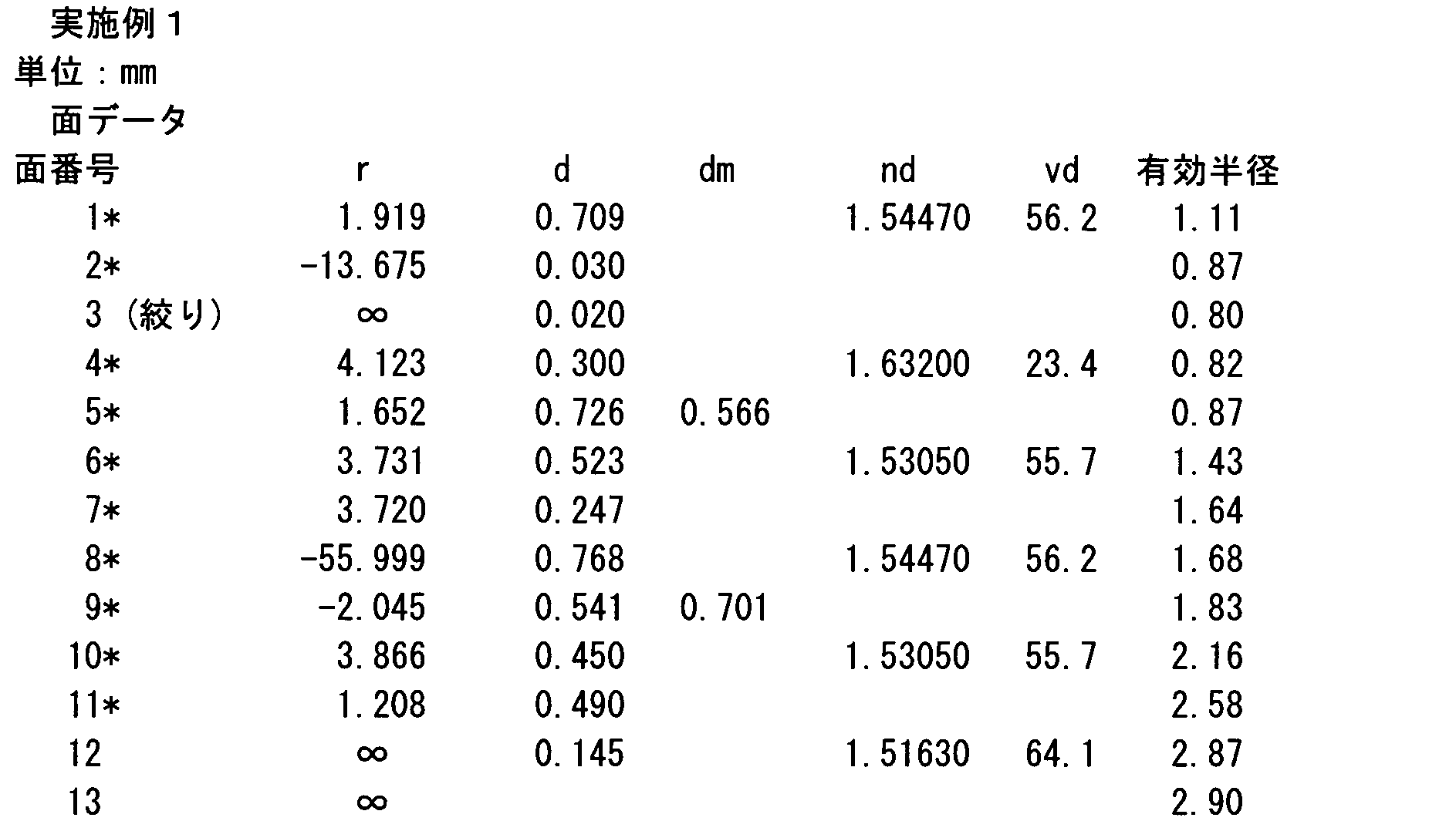
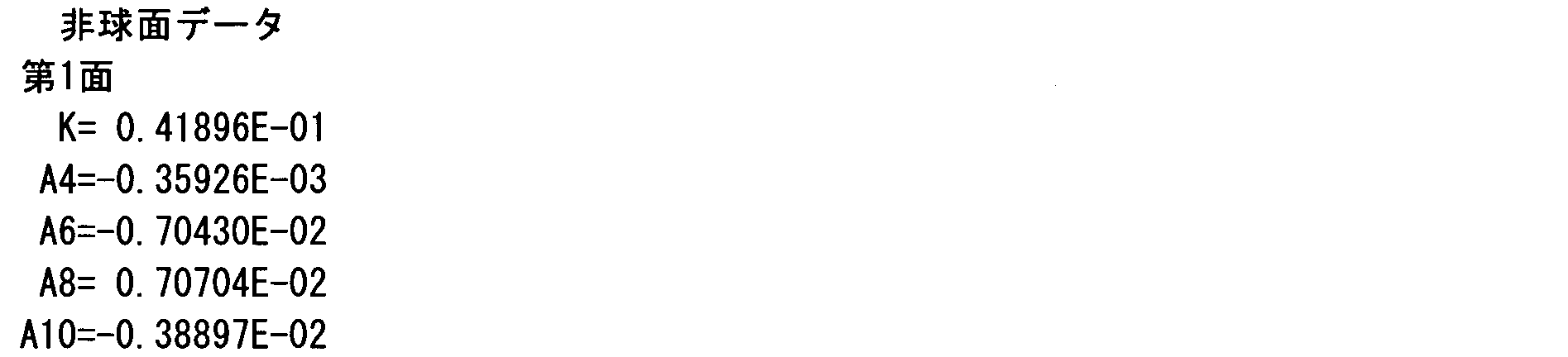

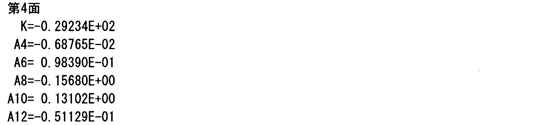


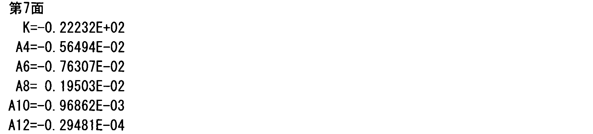
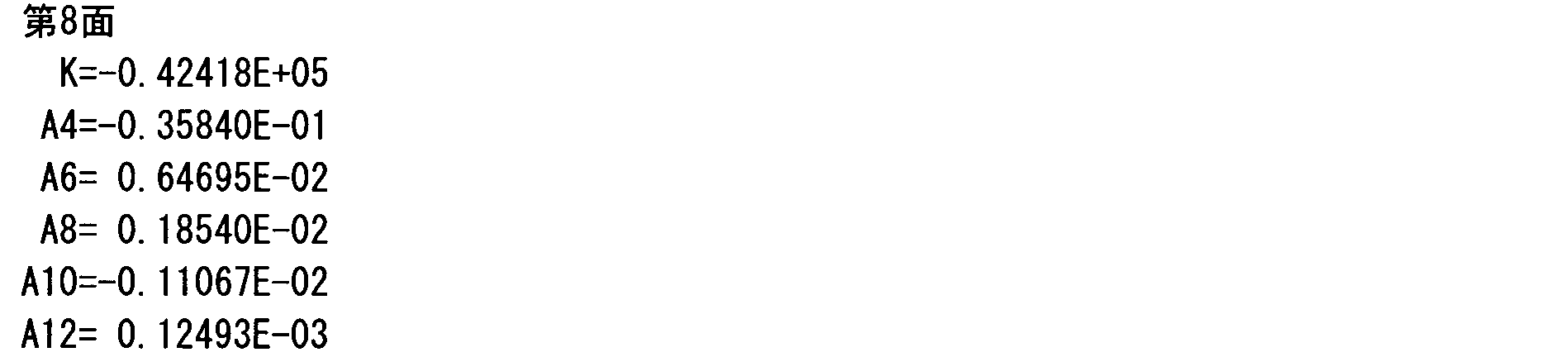


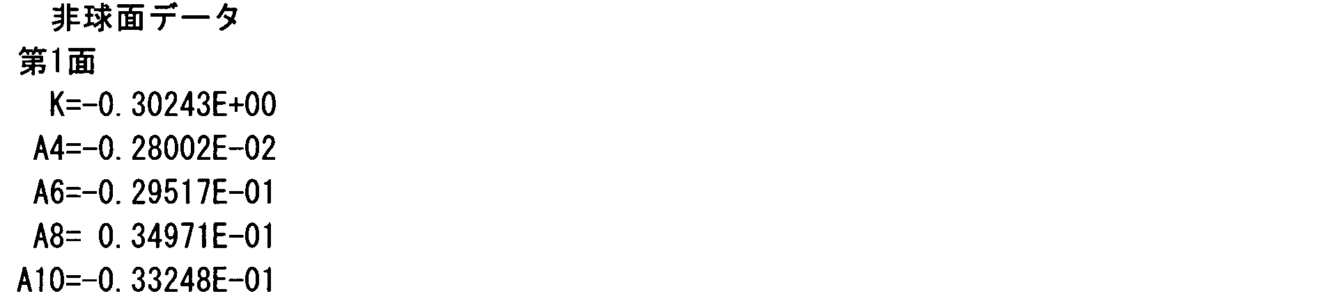


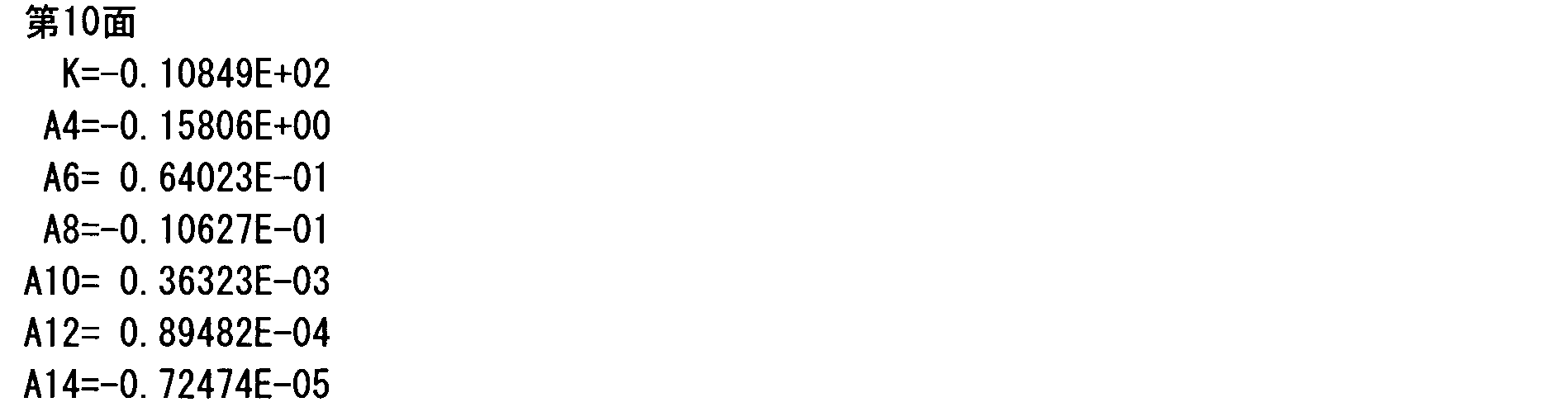


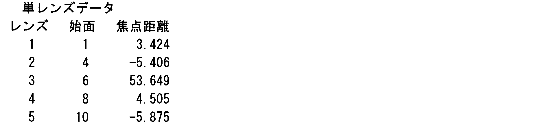




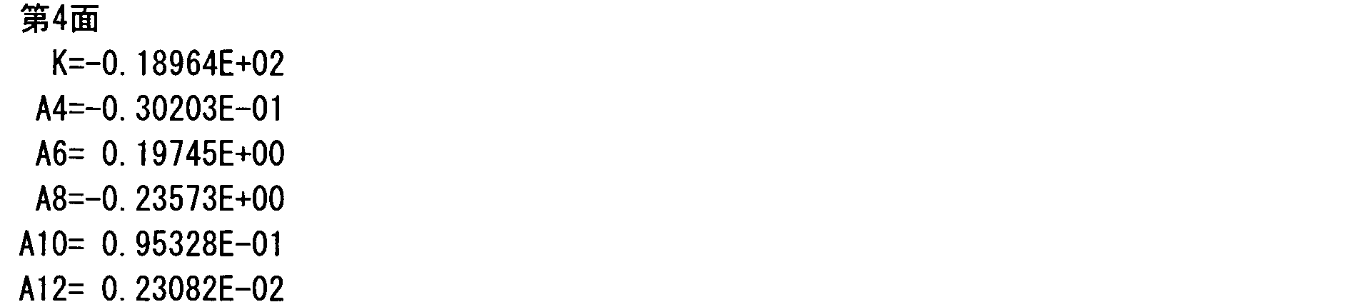


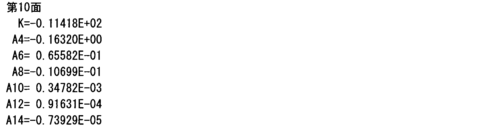
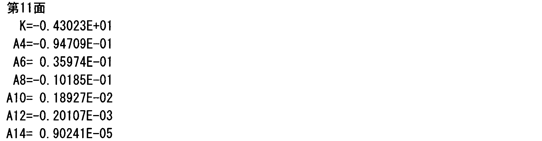
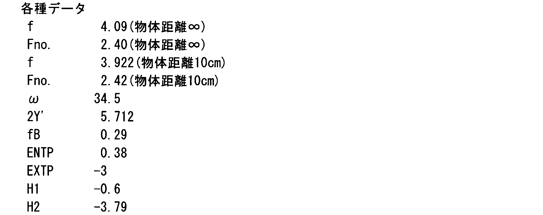


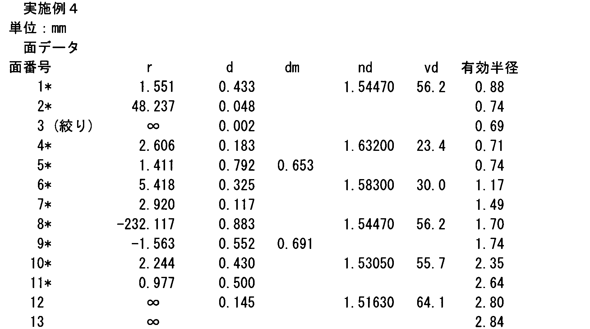


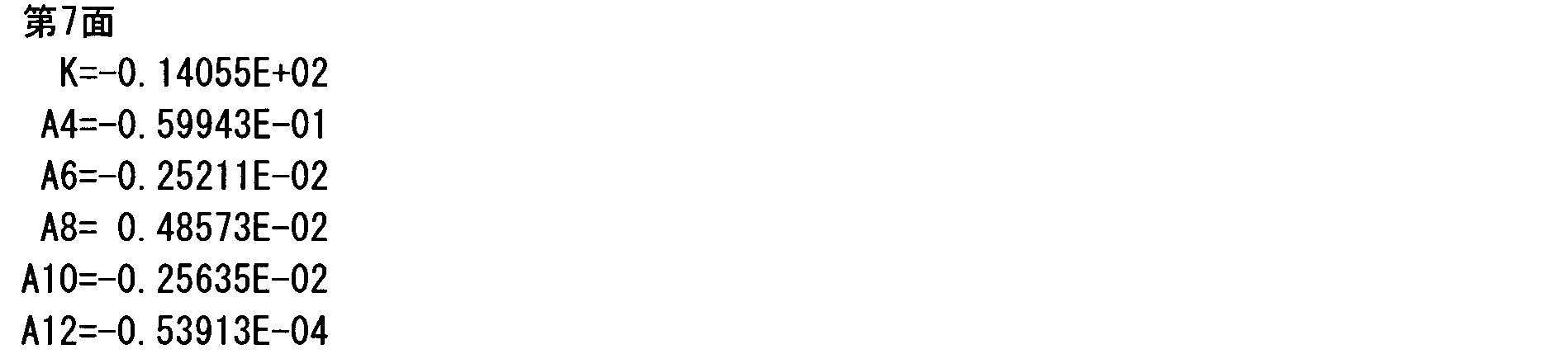





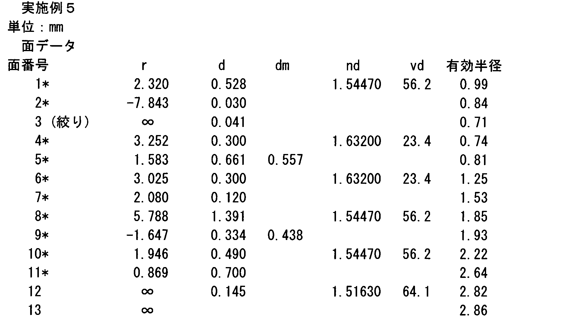

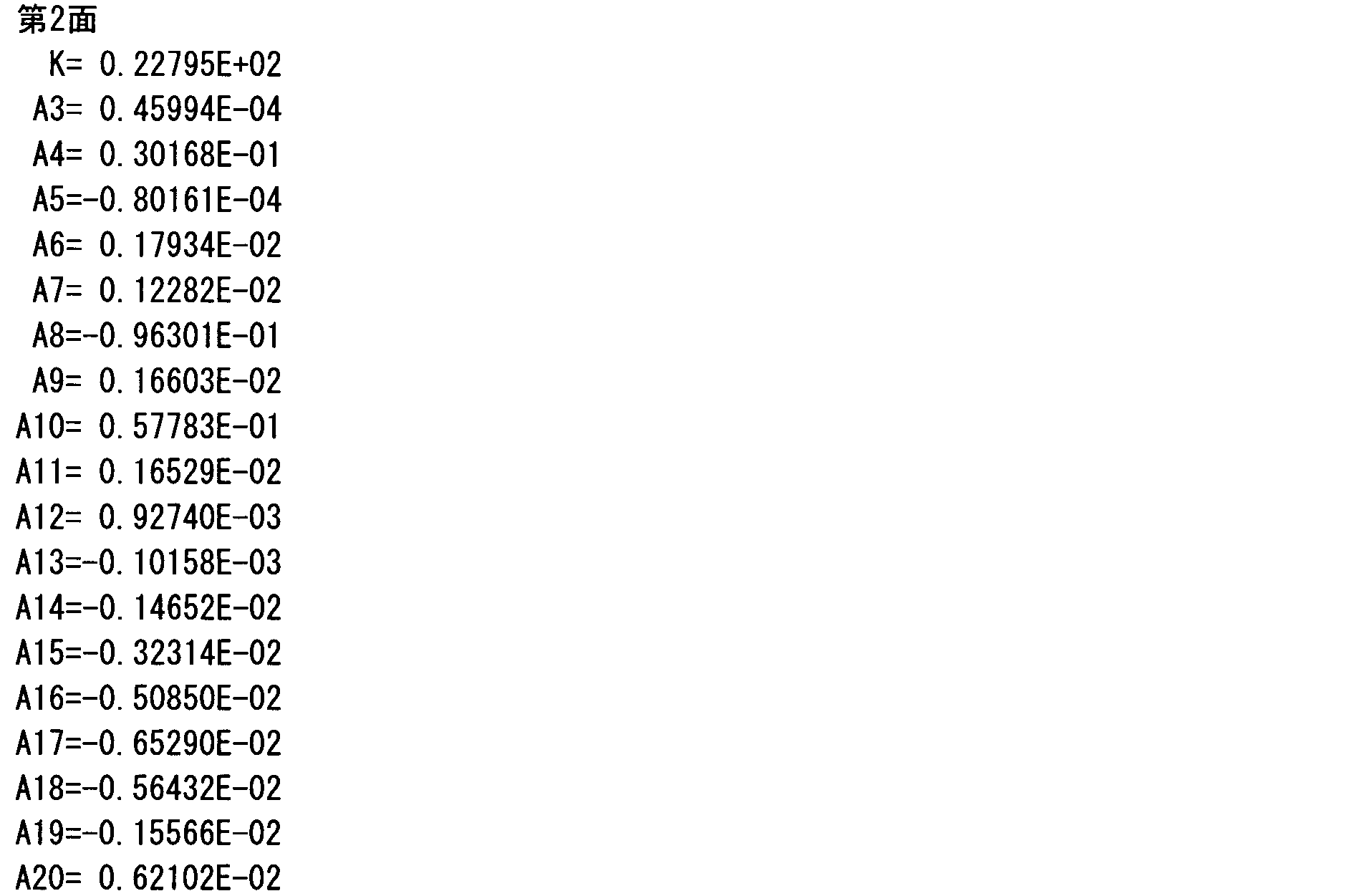
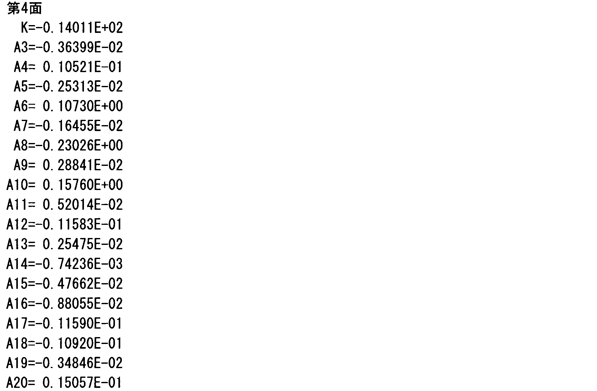


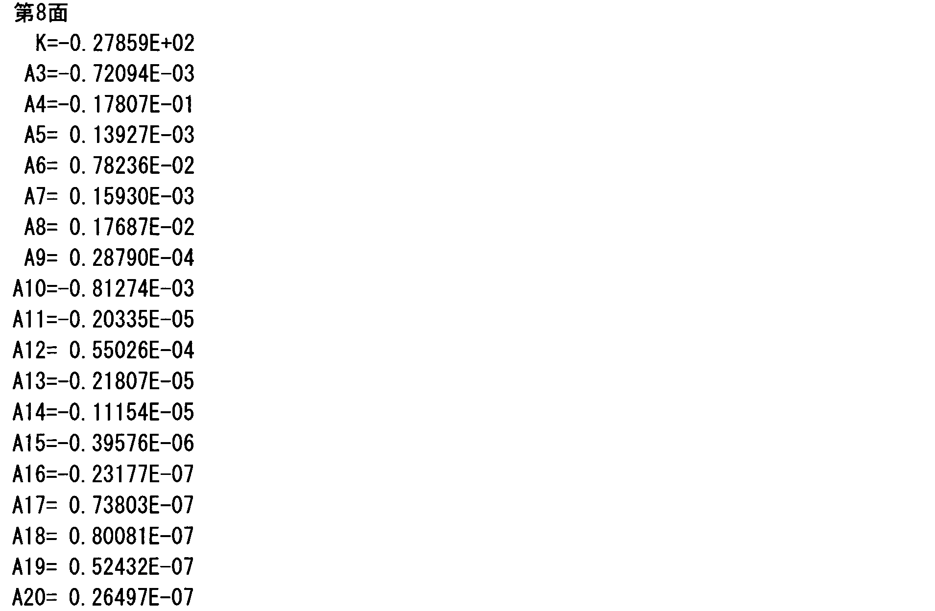
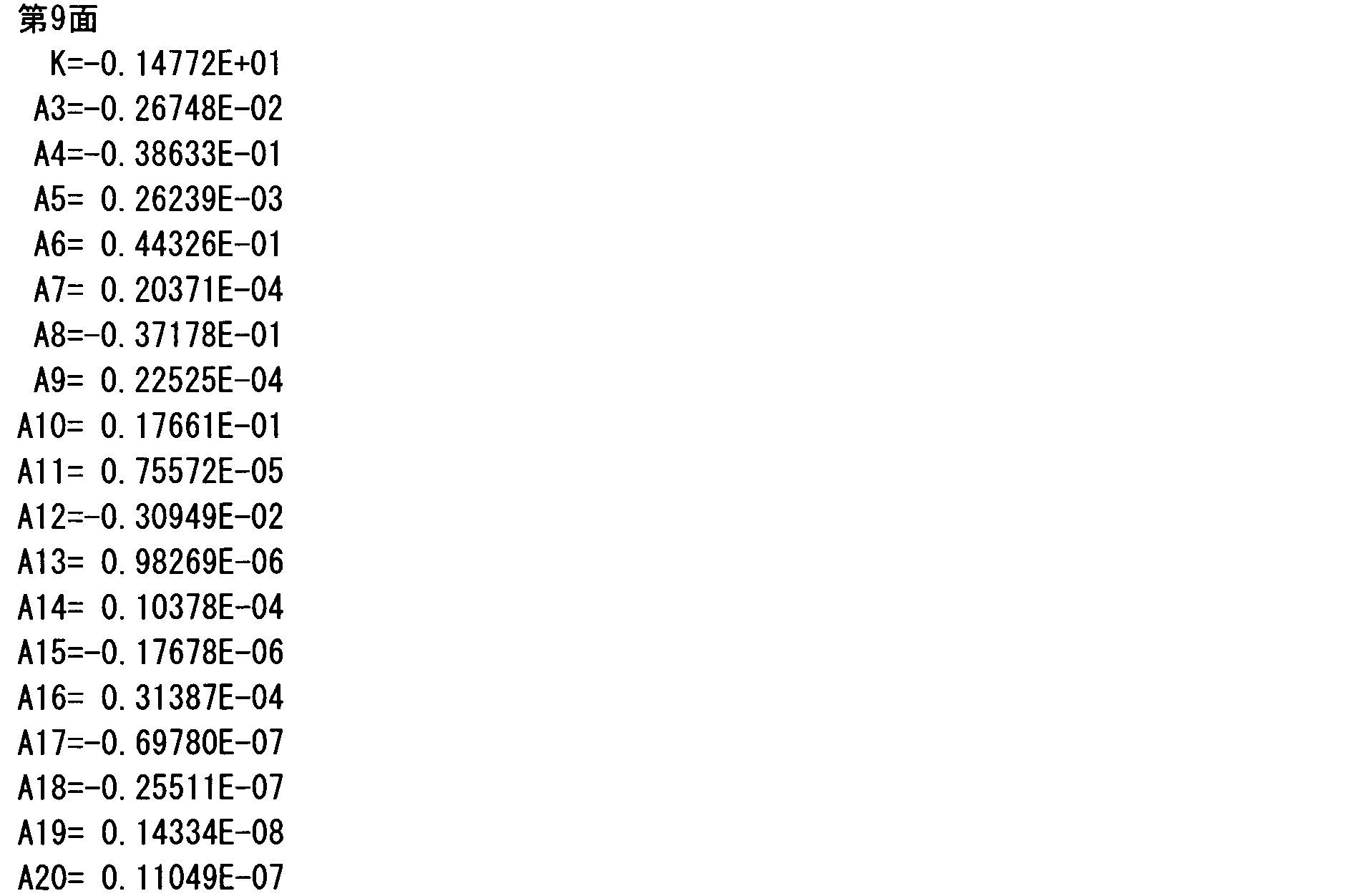




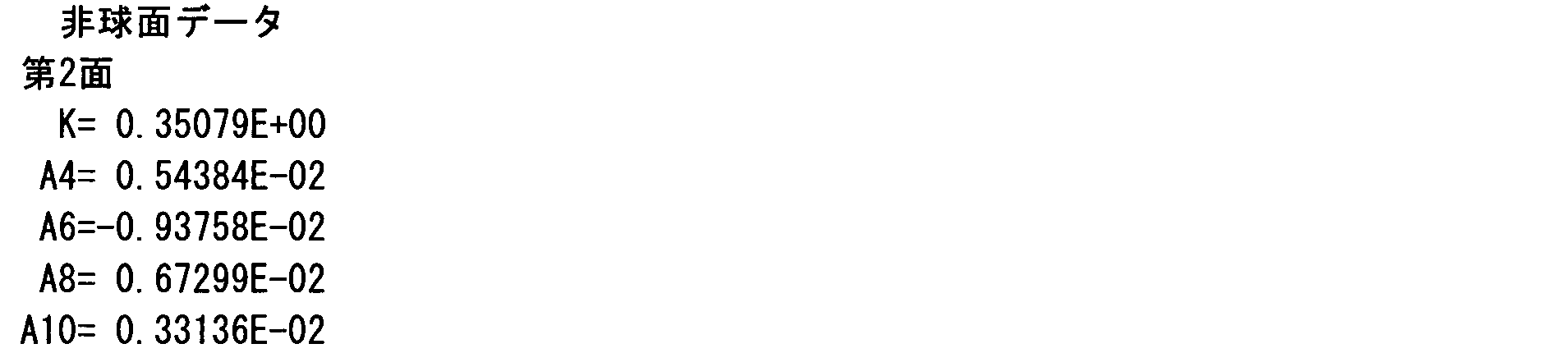


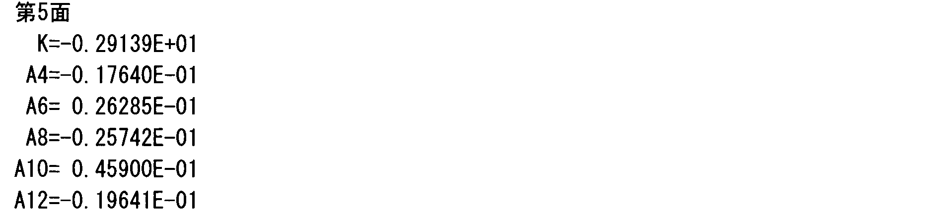


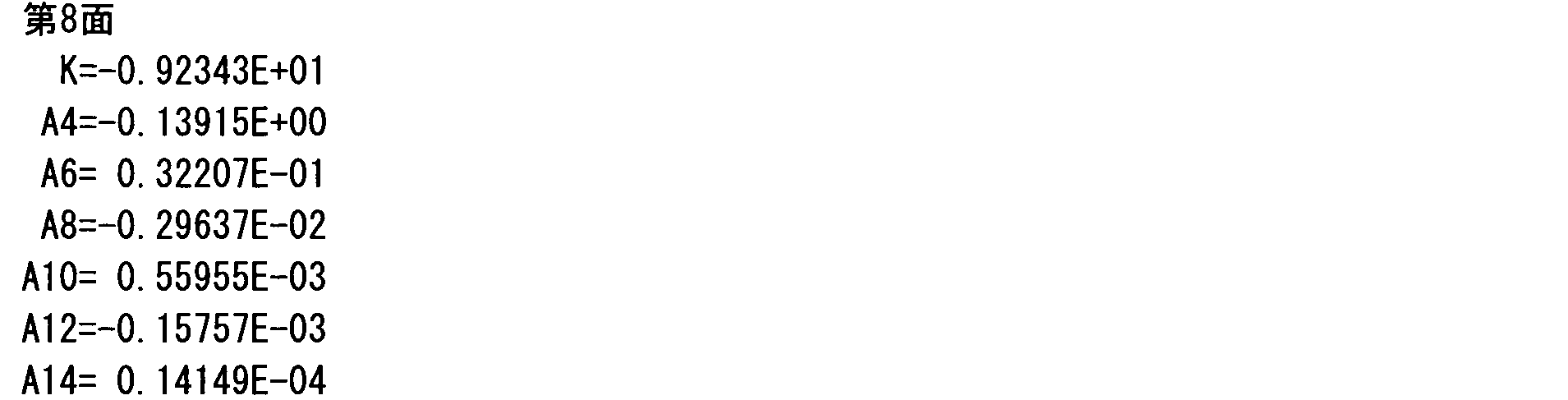





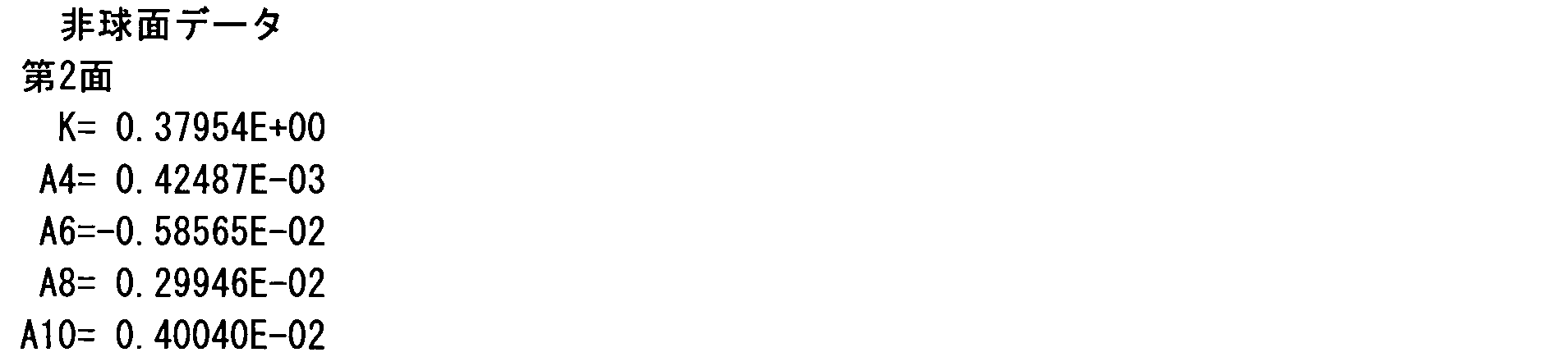

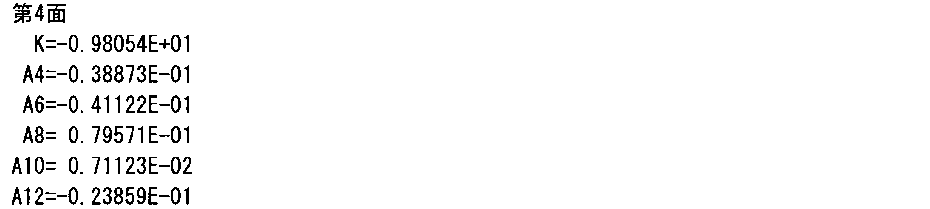

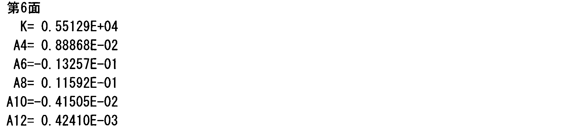
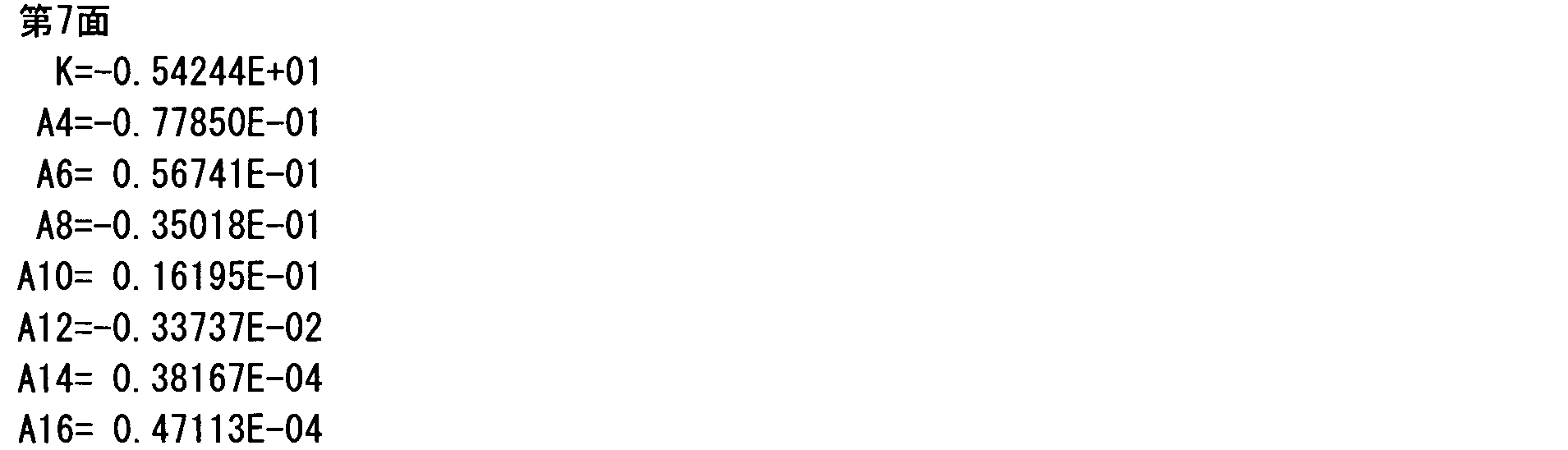
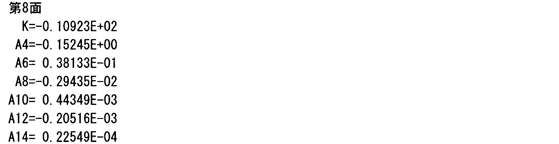
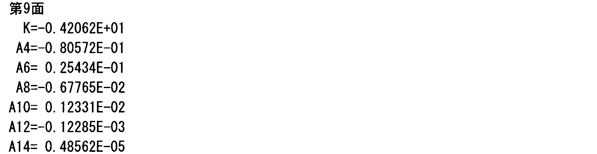


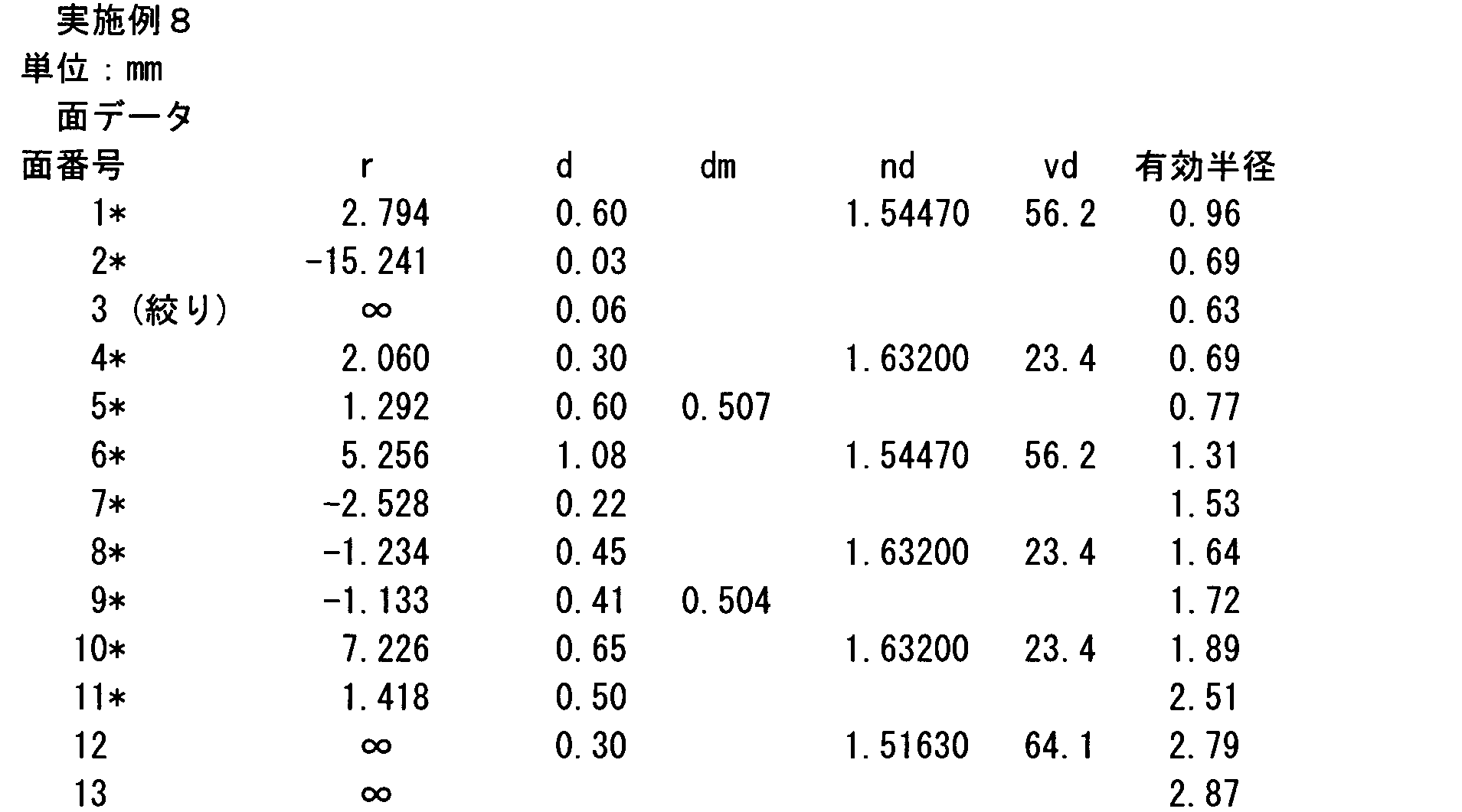


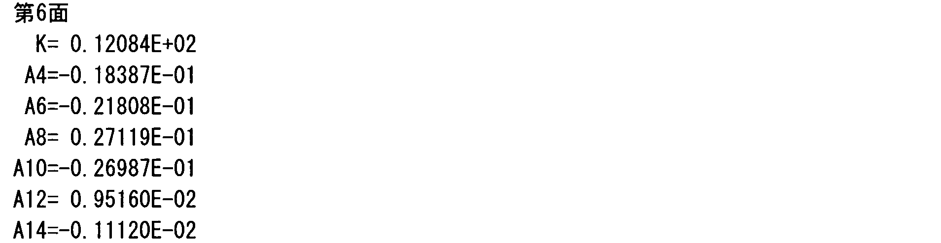
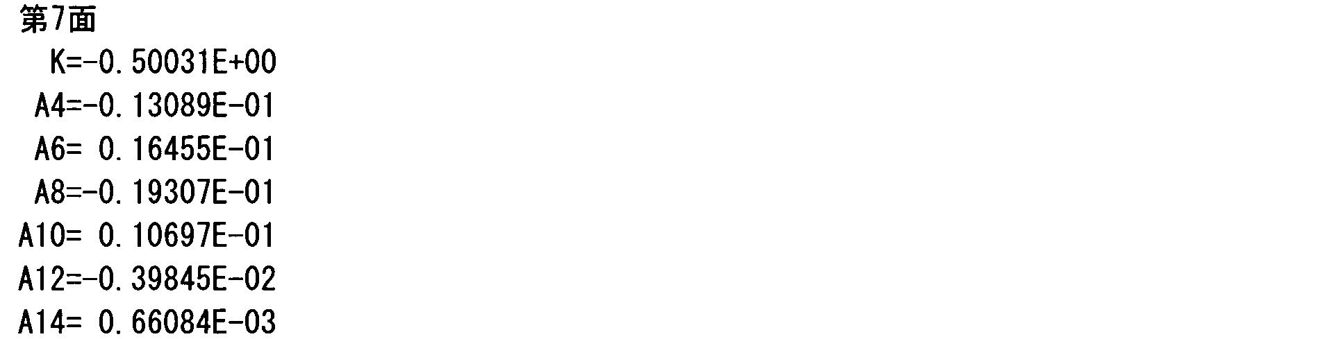
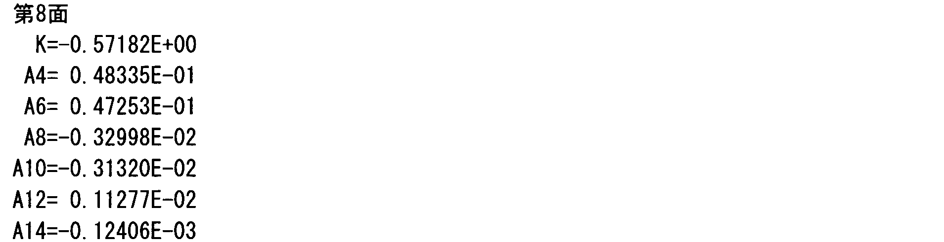
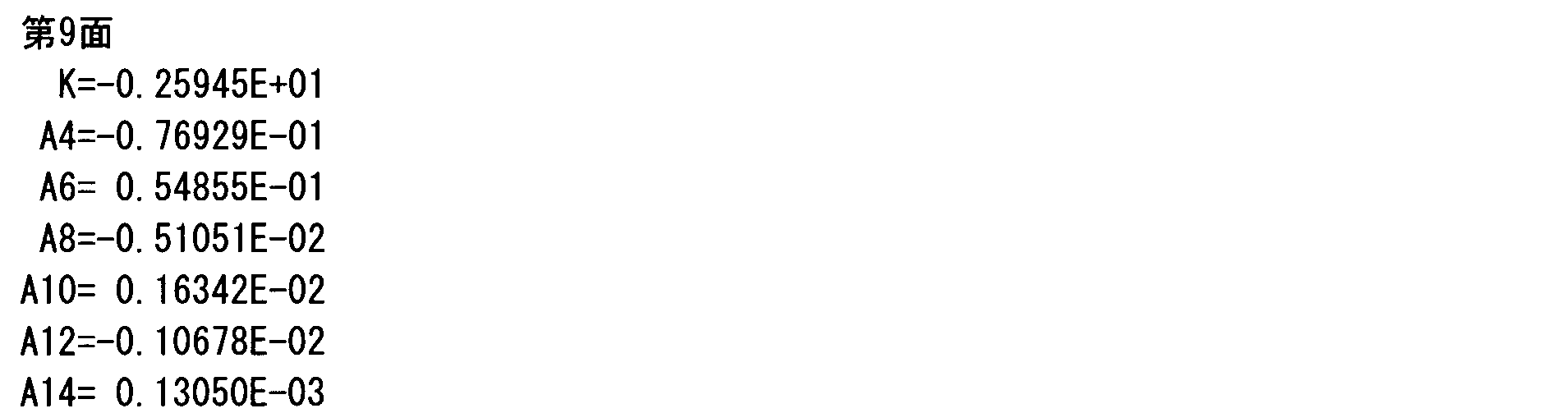

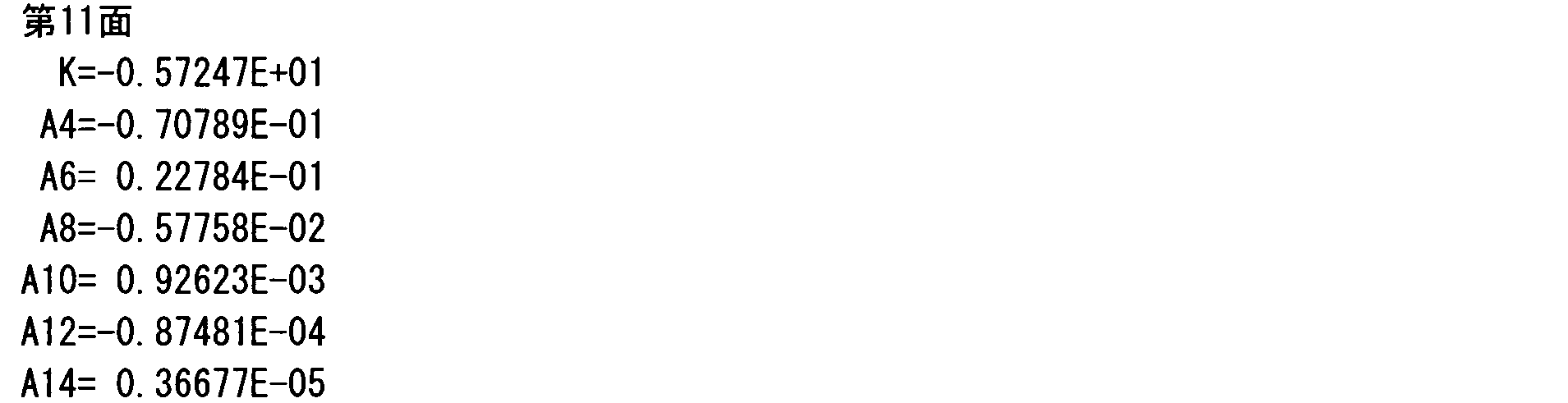

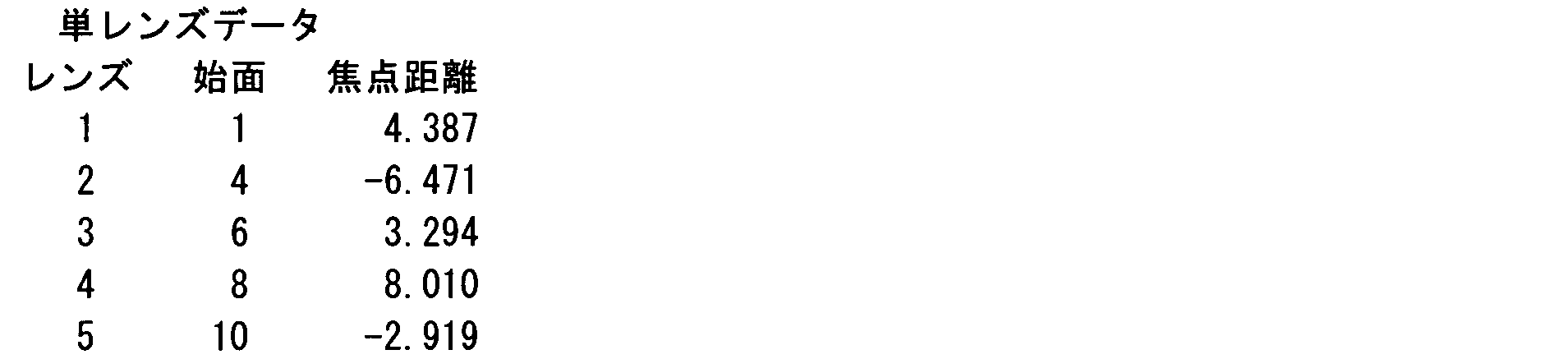

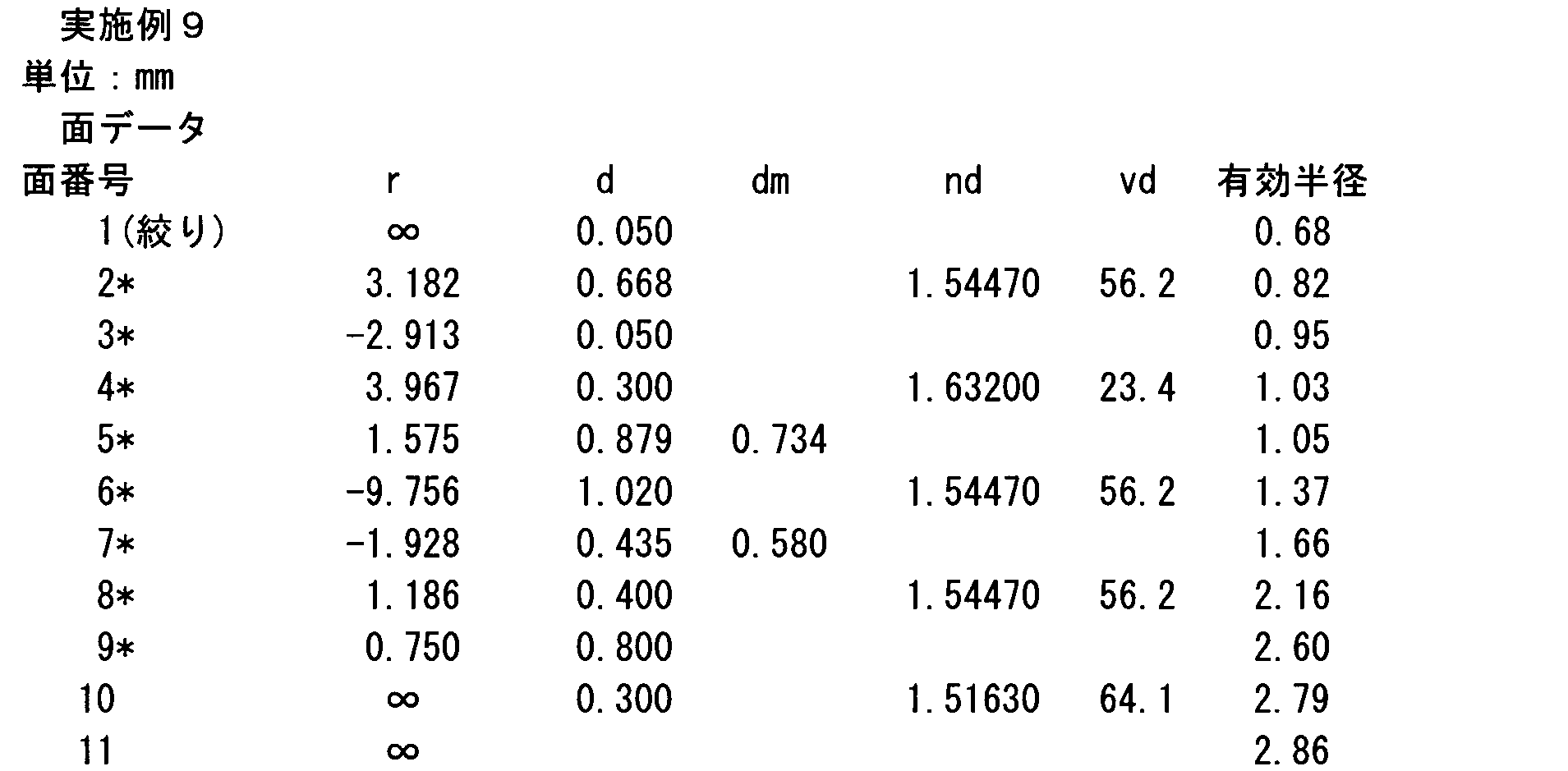


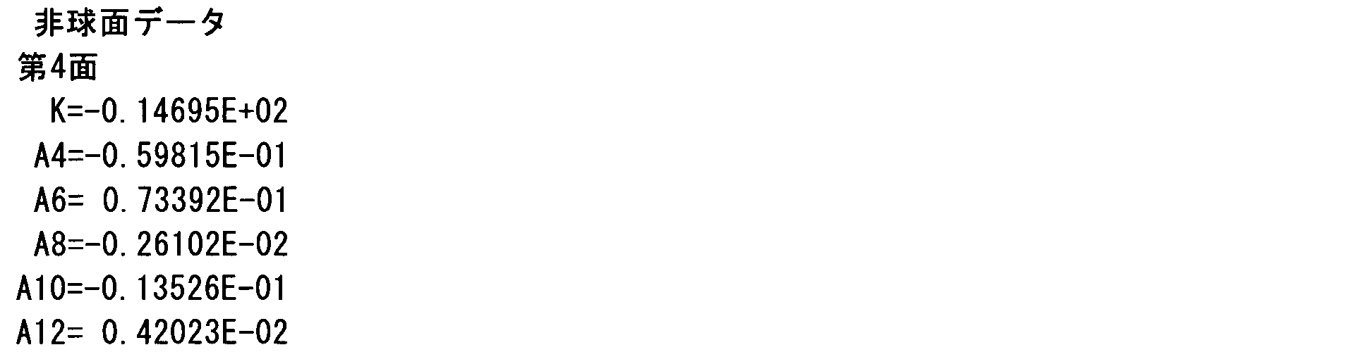


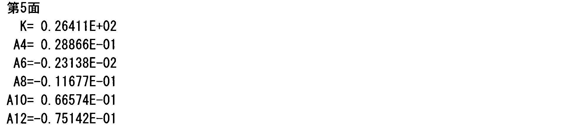


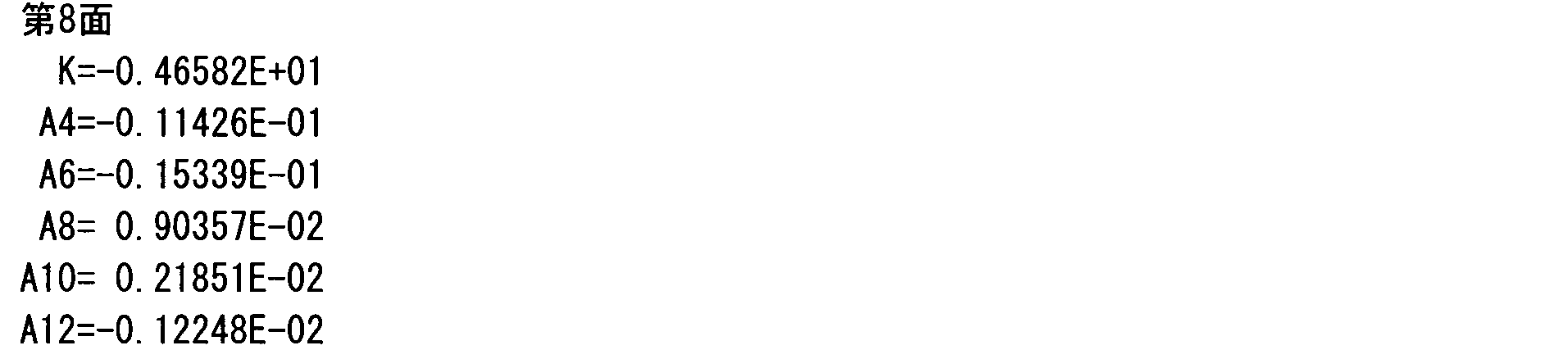


図19~図28に示すように、実施例1~10の撮像光学系は良好な収差特性を示す。また、実施例1~10いずれも条件式(1)、(2)、(3)を満足する。すなわち、本発明によれば、良好な光学特性を備える撮像光学系を精度良く、効率的に得ることが可能である。
ところで、上述した実施例では、固体撮像素子70の撮像面70aに入射する光束の主光線入射角が、撮像面70a周辺部において必ずしも十分に小さい設計にはなっていない。しかし、最近の技術では、固体撮像素子の色フィルターやオンチップマイクロレンズアレイの配列の見直しによって、シェーディングを軽減することができるようになってきている。具体的には、固体撮像素子の撮像面の画素ピッチに対し、色フィルターやオンチップマイクロレンズアレイの配列のピッチをわずかに小さく設定すれば、撮像面の周辺部にいくほど各画素に対し色フィルターやオンチップマイクロレンズアレイが撮像光学系(撮像レンズ)の光軸側へシフトするため、斜入射の光束を効率的に各画素の受光部に導くことができる。これにより固体撮像素子で発生するシェーディングを小さく抑えることができる。この点を考慮して、上述の各実施例では、より小型化を目指した設計例となっている。
(その他)
なお、本発明は以上に示した実施形態及び実施例の構成に限定されない。すなわち、本発明の目的を逸脱しない範囲で種々の変更が可能である。例えば、以上においては、位置基準マークがレンズセンタに設けられる構成を示したが、位置基準マークが設けられる位置はこの位置に限定されるものではない。例えば、レンズ周辺のコバ部(レンズの有効部の周囲に設けられる部分;例えば図2の符号L2AやL5A参照)に設けられる構成としても勿論構わない。この場合の位置基準マークは、本実施形態で示したような構成でも良いし、その他リング状等であっても構わない。
なお、本発明は以上に示した実施形態及び実施例の構成に限定されない。すなわち、本発明の目的を逸脱しない範囲で種々の変更が可能である。例えば、以上においては、位置基準マークがレンズセンタに設けられる構成を示したが、位置基準マークが設けられる位置はこの位置に限定されるものではない。例えば、レンズ周辺のコバ部(レンズの有効部の周囲に設けられる部分;例えば図2の符号L2AやL5A参照)に設けられる構成としても勿論構わない。この場合の位置基準マークは、本実施形態で示したような構成でも良いし、その他リング状等であっても構わない。
本発明は、固体撮像素子の撮像面に被写体を結像させる撮像光学系に好適である。
1 撮像光学系
13 第1のレンズホルダー(第1の保持部材)
13a レンズ保持空間
13c 接着剤充填部
13d 空間部
22 第2のレンズホルダー(第2の保持部材)
41 第1のフレーム(第3の保持部材)
70 固体撮像素子
70a 撮像面
AX 光軸
L1 第1レンズ(最物体側の正レンズ)
L2 第2レンズ
L3 第3レンズ
L4 第4レンズ
L5 第5レンズ
LG1 第1レンズ群
LG2 第2レンズ群
LG3 第3レンズ群
13 第1のレンズホルダー(第1の保持部材)
13a レンズ保持空間
13c 接着剤充填部
13d 空間部
22 第2のレンズホルダー(第2の保持部材)
41 第1のフレーム(第3の保持部材)
70 固体撮像素子
70a 撮像面
AX 光軸
L1 第1レンズ(最物体側の正レンズ)
L2 第2レンズ
L3 第3レンズ
L4 第4レンズ
L5 第5レンズ
LG1 第1レンズ群
LG2 第2レンズ群
LG3 第3レンズ群
Claims (17)
- 固体撮像素子の撮像面に被写体を結像させる単焦点の撮像光学系であって、
物体側から像側へと向かって順に、最物体側に配置される正レンズを含む少なくとも2枚のレンズからなって全体として正の屈折力を有する第1レンズ群、少なくとも1枚のレンズからなって全体として正の屈折力を有する第2レンズ群、少なくとも1枚のレンズからなる第3レンズ群を備え、
前記第1レンズ群と前記第3レンズ群とは、前記撮像面に対して固定され、
前記第2レンズ群は、フォーカス調整のために光軸方向に移動可能に設けられ、
以下の条件式を満たすことを特徴とする撮像光学系。
0.1<f1/fg2<2
但し、
f1:最物体側の正レンズの焦点距離
fg2:第2レンズ群の焦点距離 - 更に、以下の条件式を満たすことを特徴とする請求項1に記載の撮像光学系。
0.1<fg2/f<2
但し、
fg2:第2レンズ群の焦点距離
f:撮像光学系全体の焦点距離 - 更に、以下の条件式を満たすことを特徴とする請求項1に記載の撮像光学系。
1.0<fg1/f<3.0
但し、
fg1:第1レンズ群の焦点距離
f:撮像光学系全体の焦点距離 - 更に、以下の条件式を満たすことを特徴とする請求項2に記載の撮像光学系。
1.0<fg1/f<3.0
但し、
fg1:第1レンズ群の焦点距離
f:撮像光学系全体の焦点距離 - 前記第1レンズ群を保持する第1の保持部材と、前記第2レンズ群を保持する第2の保持部材と、前記第3レンズ群を保持する第3の保持部材と、を有し、
前記第1の保持部材のレンズ保持空間は、光軸と垂直な方向の直径が前記最物体側に配置される正レンズの直径よりも大きく形成されていることを特徴とする請求項1から4のいずれかに記載の撮像光学系。 - 前記第1の保持部材は、前記レンズ保持空間の周囲に調整治具を配置するための空間部を更に備えることを特徴とする請求項5に記載の撮像光学系。
- 前記第1の保持部材は、前記最物体側に配置される正レンズの側面を接着固定するための接着剤充填部を更に備え、前記空間部が前記接着剤充填部を挟むように、前記空間部と前記接着剤充填部とが前記第1の保持部材の円周方向に配列されていることを特徴とする請求項6に記載の撮像光学系。
- 前記第3レンズ群には負レンズが含まれることを特徴とする請求項1から4のいずれかに記載の撮像光学系。
- 物体側から像側へと向かって順に、最物体側に配置される正レンズを含む少なくとも2枚のレンズからなって全体として正の屈折力を有する第1レンズ群、少なくとも1枚のレンズからなって全体として正の屈折力を有する第2レンズ群、少なくとも1枚のレンズからなる第3レンズ群を備え、前記第1レンズ群と前記第3レンズ群とは撮像面に対して固定され、前記第2レンズ群はフォーカス調整のために光軸方向に移動可能に設けられる単焦点の撮像光学系の光学調整方法であって、
前記最物体側の正レンズを光軸と垂直な方向に動かして光学系全体の偏芯調整を行う調芯工程を備えることを特徴とする光学調整方法。 - 前記撮像光学系は、以下の条件式を満たすことを特徴とする請求項9に記載の光学調整方法。
0.1<f1/fg2<2
但し、
f1:最物体側の正レンズの焦点距離
fg2:第2レンズ群の焦点距離 - 前記第2レンズ群の傾きを調整する傾き調整工程を更に備え、
前記調芯工程は前記傾き調整工程後に行われることを特徴とする請求項9又は10に記載の光学調整方法。 - 前記調芯工程を行う際に、前記最物体側の正レンズを光軸方向に動かす位置調整が併せて行われることを特徴とする請求項9又は10に記載の光学調整方法。
- 前記調芯工程後に、前記第1レンズ群を光軸方向に動かす位置調整が行われることを特徴とする請求項9又は10に記載の光学調整方法。
- 前記調芯工程は、光学調整専用に準備された固体撮像素子を用いて行われることを特徴とする請求項9又は10に記載の光学調整方法。
- 前記調芯工程は、製品として組み込まれた固体撮像素子を用いて行われることを特徴とする請求項9又は10に記載の光学調整方法。
- 前記第1レンズ群には、前記最物体側に配置される正レンズとは異なるレンズであって第1の位置基準マークを有するレンズが含まれ、前記第3レンズ群には第2の位置基準マークを有するレンズが含まれ、
前記最物体側に配置される正レンズを前記第1レンズ群に含ませる前に、光軸に沿う方向から観察した場合に、前記第1の位置基準マークと前記第2の位置基準マークとが一致するように、前記第1レンズ群と前記第3レンズ群との相対位置調整が行われることを特徴とする請求項9又は10に記載の光学調整方法。 - 前記撮像光学系は、以下の条件式を満たすことを特徴とする請求項16に記載の光学調整方法。
0.1<fg2/f<2
但し、
fg2:第2レンズ群の焦点距離
f:撮像光学系全体の焦点距離
Priority Applications (1)
| Application Number | Priority Date | Filing Date | Title |
|---|---|---|---|
| CN2011800269188A CN103201665A (zh) | 2010-03-29 | 2011-03-17 | 摄像光学系统和光学调整方法 |
Applications Claiming Priority (2)
| Application Number | Priority Date | Filing Date | Title |
|---|---|---|---|
| JP2010074335 | 2010-03-29 | ||
| JP2010-074335 | 2010-03-29 |
Publications (1)
| Publication Number | Publication Date |
|---|---|
| WO2011122357A1 true WO2011122357A1 (ja) | 2011-10-06 |
Family
ID=44712073
Family Applications (1)
| Application Number | Title | Priority Date | Filing Date |
|---|---|---|---|
| PCT/JP2011/056331 Ceased WO2011122357A1 (ja) | 2010-03-29 | 2011-03-17 | 撮像光学系及び光学調整方法 |
Country Status (2)
| Country | Link |
|---|---|
| CN (1) | CN103201665A (ja) |
| WO (1) | WO2011122357A1 (ja) |
Cited By (4)
| Publication number | Priority date | Publication date | Assignee | Title |
|---|---|---|---|---|
| JP5513648B1 (ja) * | 2013-03-19 | 2014-06-04 | エーエーシーアコースティックテクノロジーズ(シンセン)カンパニーリミテッド | 撮像レンズ |
| JP2014160154A (ja) * | 2013-02-20 | 2014-09-04 | Aac Technologies Japan R&D Center Ltd | 撮像レンズ |
| CN111025515A (zh) * | 2018-10-10 | 2020-04-17 | 宁波舜宇光电信息有限公司 | 光学变焦摄像模组及其组装方法 |
| EP3605177A4 (en) * | 2017-03-24 | 2020-05-27 | Ningbo Sunny Opotech Co., Ltd. | SHARED LENS AND CAMERA MODULE AND ELECTRONIC DEVICE |
Families Citing this family (13)
| Publication number | Priority date | Publication date | Assignee | Title |
|---|---|---|---|---|
| JP5807137B1 (ja) * | 2015-07-24 | 2015-11-10 | エーエーシーアコースティックテクノロジーズ(シンセン)カンパニーリミテッドAAC Acoustic Technologies(Shenzhen)Co.,Ltd | 撮像レンズ |
| US12105350B2 (en) | 2015-10-30 | 2024-10-01 | Ningbo Sunny Opotech Co., Ltd. | Adjustable optical lens and camera module and manufacturing method and applications thereof |
| CN105445888B (zh) * | 2015-12-21 | 2020-04-03 | 宁波舜宇光电信息有限公司 | 可调光学镜头和摄像模组及其校准方法 |
| CN105445885B (zh) * | 2015-10-30 | 2019-06-18 | 宁波舜宇光电信息有限公司 | 可调光学镜头和摄像模组及其制造方法 |
| CN109709747B (zh) | 2015-12-02 | 2021-08-10 | 宁波舜宇光电信息有限公司 | 采用分体式镜头的摄像模组及其组装方法 |
| US10732376B2 (en) | 2015-12-02 | 2020-08-04 | Ningbo Sunny Opotech Co., Ltd. | Camera lens module and manufacturing method thereof |
| CN106451058B (zh) * | 2016-11-18 | 2019-12-17 | 厦门大学 | 一种激光横模模式可调控被动调q微片激光器 |
| CN109425954B (zh) * | 2017-08-22 | 2021-04-09 | 玉晶光电(厦门)有限公司 | 光学成像镜头 |
| JP2019096637A (ja) * | 2017-11-17 | 2019-06-20 | 株式会社小糸製作所 | レーザー光源ユニット |
| CN110320627B (zh) * | 2018-03-30 | 2024-06-18 | 日本电产三协(东莞)工机有限公司 | 透镜单元和该透镜单元的制造方法 |
| WO2020088039A1 (zh) * | 2018-10-31 | 2020-05-07 | 宁波舜宇光电信息有限公司 | 光学镜头、摄像模组及其组装方法 |
| CN111123458B (zh) * | 2018-10-31 | 2025-06-13 | 宁波舜宇光电信息有限公司 | 光学镜头、摄像模组及其组装方法 |
| CN115793184B (zh) * | 2021-09-09 | 2026-01-30 | 宁波舜宇光电信息有限公司 | 内对焦镜头和摄像模组 |
Citations (7)
| Publication number | Priority date | Publication date | Assignee | Title |
|---|---|---|---|---|
| JPH07199066A (ja) * | 1993-12-28 | 1995-08-04 | Nikon Corp | 大口径中望遠レンズ |
| JP2005129100A (ja) * | 2003-10-21 | 2005-05-19 | Sony Corp | 光学式ヘッド装置及びその製造方法並びに情報処理装置 |
| JP2005141091A (ja) * | 2003-11-07 | 2005-06-02 | Konica Minolta Opto Inc | レンズユニット、光ヘッド、及び光ピックアップ装置 |
| JP2006308987A (ja) * | 2005-04-28 | 2006-11-09 | Nidec Copal Corp | カメラモジュールの調整装置及び調整方法 |
| JP2008242448A (ja) * | 2007-02-28 | 2008-10-09 | Canon Inc | 光学要素保持装置 |
| JP2009192820A (ja) * | 2008-02-14 | 2009-08-27 | Fujinon Corp | 撮像レンズおよび撮像装置 |
| JP2009244699A (ja) * | 2008-03-31 | 2009-10-22 | Nikon Corp | 光学系と、光学系の合焦方法と、これらを有する撮像装置 |
Family Cites Families (3)
| Publication number | Priority date | Publication date | Assignee | Title |
|---|---|---|---|---|
| JPWO2006080184A1 (ja) * | 2005-01-25 | 2008-06-19 | コニカミノルタオプト株式会社 | 撮像装置及び該撮像装置を備えた携帯端末 |
| JP4940740B2 (ja) * | 2006-04-13 | 2012-05-30 | コニカミノルタオプト株式会社 | 撮像レンズ、撮像レンズを備えた撮像装置及び撮像装置を備えた携帯端末 |
| US7675695B2 (en) * | 2007-02-28 | 2010-03-09 | Canon Kabushiki Kaisha | Optical element holding apparatus |
-
2011
- 2011-03-17 CN CN2011800269188A patent/CN103201665A/zh active Pending
- 2011-03-17 WO PCT/JP2011/056331 patent/WO2011122357A1/ja not_active Ceased
Patent Citations (7)
| Publication number | Priority date | Publication date | Assignee | Title |
|---|---|---|---|---|
| JPH07199066A (ja) * | 1993-12-28 | 1995-08-04 | Nikon Corp | 大口径中望遠レンズ |
| JP2005129100A (ja) * | 2003-10-21 | 2005-05-19 | Sony Corp | 光学式ヘッド装置及びその製造方法並びに情報処理装置 |
| JP2005141091A (ja) * | 2003-11-07 | 2005-06-02 | Konica Minolta Opto Inc | レンズユニット、光ヘッド、及び光ピックアップ装置 |
| JP2006308987A (ja) * | 2005-04-28 | 2006-11-09 | Nidec Copal Corp | カメラモジュールの調整装置及び調整方法 |
| JP2008242448A (ja) * | 2007-02-28 | 2008-10-09 | Canon Inc | 光学要素保持装置 |
| JP2009192820A (ja) * | 2008-02-14 | 2009-08-27 | Fujinon Corp | 撮像レンズおよび撮像装置 |
| JP2009244699A (ja) * | 2008-03-31 | 2009-10-22 | Nikon Corp | 光学系と、光学系の合焦方法と、これらを有する撮像装置 |
Cited By (6)
| Publication number | Priority date | Publication date | Assignee | Title |
|---|---|---|---|---|
| JP2014160154A (ja) * | 2013-02-20 | 2014-09-04 | Aac Technologies Japan R&D Center Ltd | 撮像レンズ |
| JP5513648B1 (ja) * | 2013-03-19 | 2014-06-04 | エーエーシーアコースティックテクノロジーズ(シンセン)カンパニーリミテッド | 撮像レンズ |
| EP3605177A4 (en) * | 2017-03-24 | 2020-05-27 | Ningbo Sunny Opotech Co., Ltd. | SHARED LENS AND CAMERA MODULE AND ELECTRONIC DEVICE |
| US11659263B2 (en) | 2017-03-24 | 2023-05-23 | Ningbo Sunny Opotech Co., Ltd. | Split lens and camera module and electronic apparatus |
| US12231759B2 (en) | 2017-03-24 | 2025-02-18 | Ningbo Sunny Opotech Co., Ltd. | Split lens and camera module and electronic apparatus |
| CN111025515A (zh) * | 2018-10-10 | 2020-04-17 | 宁波舜宇光电信息有限公司 | 光学变焦摄像模组及其组装方法 |
Also Published As
| Publication number | Publication date |
|---|---|
| CN103201665A (zh) | 2013-07-10 |
Similar Documents
| Publication | Publication Date | Title |
|---|---|---|
| WO2011122357A1 (ja) | 撮像光学系及び光学調整方法 | |
| JP2011209352A (ja) | 光学系及びレンズ位置調整方法 | |
| US11422338B2 (en) | Imaging lens | |
| US11366294B2 (en) | Optical imaging lens assembly, image capturing unit and electronic device | |
| JP5740799B2 (ja) | 撮像レンズ、撮像装置及び携帯端末 | |
| US9557536B2 (en) | Zoom lens and image pickup device | |
| JP7249486B2 (ja) | 撮像光学系とそれを備える撮像装置およびカメラシステム | |
| US9897777B2 (en) | Optical system | |
| JP5699636B2 (ja) | 光学ユニットおよび撮像装置 | |
| US11460679B2 (en) | Imaging lens | |
| CN113238360A (zh) | 摄像镜头 | |
| KR20130016223A (ko) | 광학 유닛 및 촬상 장치 | |
| WO2012147841A1 (ja) | 撮像装置および電子機器 | |
| US12607834B2 (en) | Optical photographing lens, image capturing unit and electronic device | |
| JP2018109757A (ja) | 撮像光学系とそれを備える撮像装置およびカメラシステム | |
| KR20140071868A (ko) | 촬영 렌즈 및 이를 구비한 촬영 장치 | |
| KR20180119885A (ko) | 렌즈 광학계 및 이를 포함한 촬영 장치 | |
| US12210143B2 (en) | Image system lens assembly, image capturing unit and electronic device | |
| JP7612421B2 (ja) | 光学系および撮像装置 | |
| JP4593914B2 (ja) | レンズ系及びそれを有する撮像装置 | |
| JP2016170444A (ja) | 撮像装置および電子機器 | |
| JP5084879B2 (ja) | レンズ系及びそれを有する撮像装置 | |
| JP2004004928A (ja) | 撮像レンズ |
Legal Events
| Date | Code | Title | Description |
|---|---|---|---|
| 121 | Ep: the epo has been informed by wipo that ep was designated in this application |
Ref document number: 11762593 Country of ref document: EP Kind code of ref document: A1 |
|
| NENP | Non-entry into the national phase |
Ref country code: DE |
|
| 122 | Ep: pct application non-entry in european phase |
Ref document number: 11762593 Country of ref document: EP Kind code of ref document: A1 |
|
| NENP | Non-entry into the national phase |
Ref country code: JP |