WO2011122262A1 - ターゲット投影装置及びターゲット投影方法 - Google Patents
ターゲット投影装置及びターゲット投影方法 Download PDFInfo
- Publication number
- WO2011122262A1 WO2011122262A1 PCT/JP2011/055342 JP2011055342W WO2011122262A1 WO 2011122262 A1 WO2011122262 A1 WO 2011122262A1 JP 2011055342 W JP2011055342 W JP 2011055342W WO 2011122262 A1 WO2011122262 A1 WO 2011122262A1
- Authority
- WO
- WIPO (PCT)
- Prior art keywords
- target
- image
- projection
- color
- unit
- Prior art date
- Legal status (The legal status is an assumption and is not a legal conclusion. Google has not performed a legal analysis and makes no representation as to the accuracy of the status listed.)
- Ceased
Links
Images










Classifications
-
- G—PHYSICS
- G01—MEASURING; TESTING
- G01B—MEASURING LENGTH, THICKNESS OR SIMILAR LINEAR DIMENSIONS; MEASURING ANGLES; MEASURING AREAS; MEASURING IRREGULARITIES OF SURFACES OR CONTOURS
- G01B11/00—Measuring arrangements characterised by the use of optical techniques
- G01B11/24—Measuring arrangements characterised by the use of optical techniques for measuring contours or curvatures
- G01B11/25—Measuring arrangements characterised by the use of optical techniques for measuring contours or curvatures by projecting a pattern, e.g. one or more lines, moiré fringes on the object
-
- F—MECHANICAL ENGINEERING; LIGHTING; HEATING; WEAPONS; BLASTING
- F41—WEAPONS
- F41J—TARGETS; TARGET RANGES; BULLET CATCHERS
- F41J1/00—Targets; Target stands; Target holders
-
- F—MECHANICAL ENGINEERING; LIGHTING; HEATING; WEAPONS; BLASTING
- F41—WEAPONS
- F41J—TARGETS; TARGET RANGES; BULLET CATCHERS
- F41J5/00—Target indicating systems; Target-hit or score detecting systems
- F41J5/10—Cinematographic hit-indicating systems
-
- F—MECHANICAL ENGINEERING; LIGHTING; HEATING; WEAPONS; BLASTING
- F41—WEAPONS
- F41J—TARGETS; TARGET RANGES; BULLET CATCHERS
- F41J9/00—Moving targets, i.e. moving when fired at
- F41J9/14—Cinematographic targets, e.g. moving-picture targets
-
- G—PHYSICS
- G03—PHOTOGRAPHY; CINEMATOGRAPHY; ANALOGOUS TECHNIQUES USING WAVES OTHER THAN OPTICAL WAVES; ELECTROGRAPHY; HOLOGRAPHY
- G03B—APPARATUS OR ARRANGEMENTS FOR TAKING PHOTOGRAPHS OR FOR PROJECTING OR VIEWING THEM; APPARATUS OR ARRANGEMENTS EMPLOYING ANALOGOUS TECHNIQUES USING WAVES OTHER THAN OPTICAL WAVES; ACCESSORIES THEREFOR
- G03B43/00—Testing correct operation of photographic apparatus or parts thereof
-
- G—PHYSICS
- G06—COMPUTING OR CALCULATING; COUNTING
- G06T—IMAGE DATA PROCESSING OR GENERATION, IN GENERAL
- G06T3/00—Geometric image transformations in the plane of the image
Definitions
- the present invention relates to a target projection apparatus and a target projection method. More specifically, the present invention relates to a target projection apparatus capable of correcting and projecting a target image for projection on which a target is displayed so that the target projected on a measurement target can be easily identified, and a target projection method for performing projection after correction.
- JP 2007-101275 A paragraphs 0025 to 0130, FIGS. 1 to 30
- JP 2007-101276 paragraphs 0027 to 0132, FIGS. 1 to 30
- the shape of the target projected onto the measurement object may be deformed by the inclination or undulation of the measurement object.
- the target may appear larger or smaller.
- the target position can be used to detect targets such as areas with high undulations, dark areas that are not exposed to light, areas that are colored with low lightness near black, and areas that are difficult to see when reflected by light. There may be an inappropriate position.
- the target color may be difficult to see due to the color of the measurement object as the background. Thus, it may be difficult to detect the target projected on the measurement object.
- the present invention provides a target projection that can be projected again after correcting the target shape, dimensions, position, color, etc. in the target image for projection so that it can be easily detected when it is difficult to detect the target projected on the measurement target.
- An object is to provide an apparatus and a target projection method.
- the target projection apparatus 1 projects a projection target image F1 on which a target T is displayed onto a measurement object 2 as shown in FIG. Unit 3, photographing unit 4 that projects projection target image F ⁇ b> 1 from projection unit 3 to photograph target image F ⁇ b> 2 projected on measurement object 2 to obtain photographed image F ⁇ b> 3, and photographed image photographed by photographing unit 4
- a target feature detection unit 62 for detecting the feature of the target T from F3, an allowable condition storage unit 54 for storing a predetermined allowable condition regarding the characteristic of the target T in the captured image F3, and a target allowable condition for the target T in the captured image F3
- the allowable condition determining unit 7 that determines whether or not the condition is satisfied and the allowable condition determining unit 7 determines that the predetermined allowable condition is not satisfied, the predetermined allowable condition is satisfied.
- an image processing unit 8 for correcting the projected target image F1 by changing the characteristics of the target T as.
- a CRT method a liquid crystal method (transmission type, reflection type), a DLP (digital light processing) method, or the like
- a CRT screen, a liquid crystal display screen, a screen projected on a monitor by a micromirror, or the like can be used as the projection target image F1.
- the characteristics of the target T in the captured image include the shape, dimensions, colors, position coordinates, rotation angles, and the like of the target.
- the predetermined allowable condition a condition (range, etc.) regarding the characteristics of the target can be cited.
- the target projection device 1 projects a projection target image F ⁇ b> 1 on which a target T is displayed onto a measurement object 2, and a projection unit
- the target image F2 projected onto the measurement object 2 by projecting the projection target image F1 from 3 is obtained to obtain the first photographed image F3B, and the illuminated measurement object 2 is photographed to obtain the second photographed image F3A.
- the allowable condition storage unit 54 that stores the condition of the inappropriate region for projecting the target T on the measurement object 2,
- the inappropriate region extracting unit 63 for extracting an inappropriate region for projecting the target in the photographing object 2 and the allowable condition determining unit 7 extract the inappropriate region
- the target in the projection target image F1 is extracted.
- Tsu DOO T is to modify the characteristics of the target T so as not to be projected to the inappropriate region and an image processing unit 8 for correcting the projected target image F1.
- the first captured image F3B is a captured image including the target T
- the second captured image F3A is a captured image not including the target T.
- the illumination it is better to project the projection white image F0 (not shown) from the projection unit 3 under the same projection conditions as the projection of the projection target image F1, but other illumination light is used. Or natural lighting with sunlight may be used.
- region which reflects a low brightness area
- “reflection” means regular (specular) reflection.
- the “reflecting region” corresponds to a region having a high reflectivity where the target projected by the reflected light cannot be identified.
- the projection unit 3 can project the projection white image F0 onto the measurement target 2.
- the imaging unit 4 captures the measurement object 2 illuminated with the projection white image F0 to obtain a second captured image F3A.
- the white image F0 for projection for example, an image in which the entire liquid crystal screen is displayed in white can be used. Constituting as in this aspect is convenient because the projection target image F1 and the projection white image F0 can be formed using the same display screen.
- the projection white image F0 is irradiated under the same projection conditions as the projection target image F1. If comprised in this way, the process which produces the difference image and composite image of the target image F1 for projection and the white image F0 for projection will become efficient and easy.
- the target T is characterized by the shape, size, color, position coordinate, rotation angle, target of the target T. It includes at least one of the number and arrangement when T is plural.
- the predetermined allowable condition is that the target T has characteristics (target shape, size, color, position coordinate, rotation angle, and multiple targets). Number, arrangement, relationship between target and background, etc.) (range, etc.). If comprised in this way, the characteristic of the target T can be correct
- the inappropriate region is a low-lightness region or a region that reflects light, as shown in FIG. 10 or FIG. It is.
- the low-lightness region include a region where black and a color close to black are colored, and a dark region such as a shade and a shade. If comprised in this way, it can correct
- the target projection apparatus 1 can use a color code target CT as the target T as shown in FIGS. 1 and 2, for example, in any of the first to seventh aspects.
- the target detection unit 6 detects the position detection pattern of the color code target CT and the color code pattern for code identification from the captured image F3.
- the color code target CT refers to a target in which individual targets can be identified by the color code color scheme. If comprised in this way, since each target can be identified if color code target CT is used, three-dimensional measurement can be performed efficiently with high reliability.
- a specific projection target image F1 made up of a color code target CT alone can be selected as a reference color code target.
- the selected reference color code target is projected onto a white screen, and the histogram related to the color of the color code target CT of the captured image F3 obtained by shooting the target image F2 is the histogram related to the color of the reference color code target.
- a specific color code target CT may be selected from a specific projection target image F1.
- the selected specific projection target image F1 is projected onto a white screen, and the histogram relating to the color of the specific color code target CT in the captured image F3 obtained by capturing the target image F2 is the reference color code target.
- a histogram related to the color of the reference color code target CT a histogram related to the entire color code target CT may be used.
- a histogram relating to a part of the color code target CT, for example, the reference color portion P2 may be used.
- a histogram creation unit that creates a histogram related to the color of the photographed image F3 as a measurement histogram.
- the allowable condition storage unit 54 stores predetermined allowable conditions related to the characteristics of the histogram relating to the color of the captured image F3, and the allowable condition determination unit 7 based on the characteristics of the measurement histogram generated by the histogram generation unit 65.
- the image processing unit 8 determines whether or not the selected region in the captured image F3 satisfies a predetermined allowable condition, and the image processing unit 8 determines whether the predetermined allowable condition is not satisfied by the allowable condition determining unit 7 Then, the color of the projection target image F1 is corrected so as to satisfy a predetermined allowable condition.
- the target projection device projects the projection target image F1 edited by the image processing unit 8 onto the measurement object 2 and shoots it.
- the unit 13 is provided. With this configuration, it is convenient to immediately perform a three-dimensional measurement with the same apparatus using the detected position coordinates of the target T.
- the target projection method is a first method of projecting a projection target image F1 on which a target T is displayed onto a measurement object 2 as shown in FIG.
- This aspect is an aspect of the target projection method corresponding to the target projection apparatus 1 according to the first aspect.
- the target projection that can be projected again after correcting the features such as the shape, size, position, and color of the target in the projection target image F1 to be easily detected. Can provide a method.
- FIG. It is a figure which shows the structural example of the target projector in Example 1.
- FIG. It is a figure which shows the example of a color code target. It is explanatory drawing of the gravity center position detection using a retro target. It is a figure which compares and shows RGB color space and HSI color space. It is a figure which shows arrangement
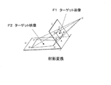
- FIG. 7 shows an example of correction by projective transformation.
- An example in which the shape of the target T is a square in the target image F2 projected after the correction will be shown.
- FIG. 7 illustrates the case where the surface of the measuring object 2 is a plane, but when the surface of the measuring object 2 is a curved surface, the curved surface portion is divided into a plurality of small planes (Equation 3) and (Equation 4). ) Conversion formula may be applied.
- a corrected image can be created using a conversion formula of (Formula 3) and (Formula 4) for an arbitrary shape, for example, a circular or star target.
- the enlargement / reduction ratio m performed by correction may be appropriately adjusted.
- the enlargement / reduction ratio m may be adjusted so that the dimension of the retro target in the captured image F3 is within 10 to 18 pixels.
- the projection unit 3 may adjust the magnification m.
- Vertices can be detected as part of edge detection.
- a region including the edge is stored in the allowable condition storage unit 54 as an inappropriate region with a margin. Then, in the projection target image F1, the position of the target T at the coordinate position corresponding to the inappropriate area may be moved so as to avoid the coordinate position.
- the following correction is also possible.
- the target shape in the photographed image F3 is distorted from a square and the deviation of the length of the side is + 6%
- the length of the side in the projection target image F1 is (100-6) / 100 times.
- the apex angle is 96 degrees
- an apex angle in the projection target image F1 may be corrected by a 90 2/96 degrees.
- the retro target size in the captured image F3 is 20 pixels
- the target size in the projection target image F1 may be 14/20 times (14 pixels is a median of 10 to 18 pixels).
- the target brightness in the projection target image F1 is corrected by 3 in the ⁇ (minus) direction
- the hue change of the reference color is an average of +35 degrees in the HSI color system
- the target hue in the projection target image F1 may be corrected by 35 degrees in the ⁇ (minus) direction.
- the target rotation angle in the captured image F3 is +6 degrees
- the target rotation angle in the projection target image F1 may be corrected by 6 degrees in the ⁇ (minus) direction.
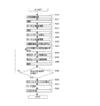
- the edge or vertex of the measurement object 2 is detected by the inappropriate area extraction unit 63 (S136).
- the inappropriate area extraction unit 63 As described above, for example, a technique of obtaining a zero crossing point with a LOG filter can be used. Vertices are also detected as part of the edge.
- the detected edge is stored in the allowable condition storage unit 54 as an inappropriate area with a margin for the area including the edge (S138).
- the target position detector 61 detects the color code target CT from the captured image F3 (S140). That is, a circular target (retro target) of the retro target portion P1 at the three corners of the color code target CT is detected. Since it is difficult to detect when the circular target is in the belt-like dark region Q1, if any of the three corner circular targets is not detected, the color code target CT is applied to the belt-like dark region Q1 and becomes an inappropriate region. There will be. In some cases, the shape, size, and the like of the color code target CT do not satisfy predetermined allowable conditions.
- the image converter 81 corrects the distortion using, for example, projective transformation. Further, if there is a difference in the distance from the camera of the projection unit 3 depending on the location of the measurement object 2, a difference occurs in the size of the color code target CT in the target image F2.
- the size of the circular target in the photographed image F3 is 10 to 18 pixels, the center of gravity of the circular shape is accurately obtained, so that the size of the circular target in each color code target CT is within this range in the image conversion unit 81.
- Each color code target CT is corrected by enlarging or reducing it.
- color code target CTs having different dimensions. This is because the distance from the camera is different on the surface of the measurement object 2, so that the size of the color code target CT is changed on the projection target image F1. This is because the projection is performed with substantially the same dimensions when projected.
- the color correction unit 83 corrects the color of the projection target image F1 in accordance with the change of the reference color. Also, the color code target CT Is tilted and does not satisfy the predetermined permissible condition, the image moving unit 82 is rotated in the direction opposite to the tilt to correct the predetermined permissible condition. Further, even when the number and arrangement of the color code targets CT do not satisfy a predetermined allowable condition, correction is performed so as to satisfy the predetermined allowable condition. For example, the color addition target deletion unit 84 adds or deletes the color code target CT.
- the allowable condition determination unit 7 determines again whether or not each color code target CT satisfies a predetermined allowable condition (S190). If there is an inappropriate color code target CT that does not satisfy the predetermined permissible condition, the process returns to S160, corrects again, and repeats until there is no such inappropriate color code target. If there is no inappropriate color code target, the process ends.
- the corrected projection target image F4 is stored in the corrected image storage unit 55.
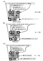
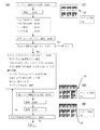
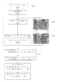
- FIG. 11 shows another example of target image correction processing.
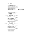
- FIG. 11A shows a processing flow diagram thereof.
- FIG. 11C shows the target image F2 projected onto the measurement object 2 using the first projection target image F1, and the projection target image F4 corrected in FIG. 11D.
- each color code target CT is corrected so as to be projected while avoiding the region Q3 where the band-like light of the measuring object 2 is reflected.
- the area Q4 where the band-like light is reflected is an area corresponding to the area Q3 where the band-like light of the measurement target 2 is reflected, although it does not actually exist in the projection target image F1.
- the point that the color code target CT becomes difficult to see is the same as the case where there is a band-like dark region Q1. Since there is no other difference, the same processing flow as the example shown in FIG. 10 can be applied.
- the allowable condition determination unit 7 determines whether or not the target of the corrected projection target image F4 satisfies a predetermined allowable condition (S190).
- the shape, dimensions, color, position, etc. of the target are usually corrected so as to be suitable for three-dimensional measurement, which is suitable for three-dimensional measurement. If the shape, size, color, position, etc. of the target are still inappropriate, the shape, size, color, position, etc. of the target in the projection target image F1 are further corrected. If suitable, the color code target CT is then detected from the captured image F6 by the target position detection unit 61 according to the color code target CT detection flow (S200).
- the target of the projection target image projected onto the measurement target is difficult to detect, it is easy to detect the shape, size, color, and position of the target in the projection target image.
- the example in which the projection target image F1 is projected onto the measurement object 2 and the target that does not satisfy the predetermined allowable condition is extracted and corrected from the captured image F3 has been described.
- An example of extracting and correcting a target in an inappropriate region from the captured image F3 of the measurement object 2 illuminated with the white image F0 will be described. Differences from the first embodiment will be mainly described.
- the apparatus configuration can be the same as that of the first embodiment (see FIG. 1). It is the same except that the projection unit 3 uses the projection white image F0 instead of the projection target image F1 in the first projection, and the inappropriate region is estimated instead of the target detection.
- the projection unit 3 projects the projection white image F0 onto the measurement object 2 (S110). Thereby, the measuring object 2 is illuminated. At this time, if there is a band-like dark area Q1 in the measurement object 2, the band-like dark area appears to overlap the illuminated image of the measurement object 2, as shown in FIG. Next, the measurement object 2 illuminated by the photographing unit 4 is photographed (S115). As a result, an illuminated captured image F3A of the measurement object 2 similar to that shown in FIG. 13B is obtained.
- the captured image F3A also includes a belt-like dark region Q1.
- the position of the color code target CT is arranged so as to avoid position coordinates corresponding to these inappropriate areas (S165).
- the color code target CT may be arranged with correction based on the existing projection target image F1, or a new projection target image F4 may be generated.
- the projection unit 3 projects the newly arranged projection target image F4 (S170).
- projection is performed using a projection target image F4 as shown in FIG.
- the band-shaped dark area Q2 in FIG. 13D is an area corresponding to the band-shaped dark area Q1 of the measurement target 2 although it does not actually exist in the projection target image F1.
- a target image F5 projected onto the measurement object 2 is, for example, as shown in FIG.
- each color code target CT is projected while avoiding the band-like dark area Q1 of the measuring object 2.
- targets having different dimensions on the projection target image F4 are projected with substantially the same dimensions.
- the target image F5 is photographed (S180). As a result, a captured image F6 similar to that shown in FIG.
- FIG. 14 shows another example of target image correction processing.
- FIG. 14A shows a processing flow diagram thereof.
- FIG. 14B shows the target image F2 in the case where it is estimated that the illumination target image F1 is projected on the measurement target 2 in FIG. 14C.
- FIG. 14E shows the target image F5 projected onto the measurement object 2 using the corrected or generated projection target image F4.
- the belt-like dark region Q1 shown in FIG. 13 there is a region Q3 where the belt-like light is reflected.
- each color code target CT is arranged so as to be projected while avoiding the region Q3 where the band-like light of the measuring object 2 is reflected.
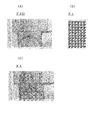
- FIG. 15 shows an example in which targets are arranged avoiding inappropriate areas.
- FIG. 15A shows a processing flow diagram thereof.
- FIG. 15B shows a photographed image of the measurement object 2
- FIG. 15C shows features such as edges detected from the photographed image
- FIG. 15D shows a region with few features in the photographed image.
- region with few features at 15 (E) is shown.
- the projection white image F0 is projected onto the measurement object 2 by the projection unit 3 (S310). Thereby, the measuring object 2 is illuminated. If the measurement object 2 has undulations such as edges, the amount of reflected light changes.
- the measurement object 2 illuminated by the photographing unit 4 is photographed (S320). Thereby, a captured image F3A as shown in FIG. 15B is obtained. A change occurs in the amount of received light in the captured image F3A in accordance with a change in the amount of reflected light at each part of the measurement object 2. A change in the amount of received light increases due to an edge or the like.
- feature extraction is performed as detection of an inappropriate region (S330). For feature extraction, for example, a line detection operator or a canny operator may be used. Further, the edge extraction by the LOG filter described in the first embodiment can be used. Thereby, as shown in FIG. 15C, an edge in the captured image F3A is extracted.
- FIG. 15C an edge in the captured image F3A is extracted.
- an area having no feature or a small area is extracted from the image from which the edge is extracted (S340). For example, a threshold is provided for the density of feature points, and an area below the threshold is extracted.
- the projection target image F4 is edited so that the color code target CT is arranged only in such an extracted feature-free region or a small region (S350). The editing may be performed based on the existing projection target image F1 and the color code target CT may be arranged, or a new projection target image F4 may be generated.
- the projection target image F4 corrected or generated by the projection unit 3 is projected onto the measurement object 2 (S360). In the target image F5 when the corrected or generated projection target image F4 is projected onto the measurement object 2, as shown in FIG. Yes.
- Example 3 the measurement object 2 is colored, and the projection white image F0 is projected onto the measurement object 2 to obtain a photographed image, and the projection target image F1 is obtained using a negative image or the like of the photographed image.
- An example of re-projecting after correcting the color so that it can be easily distinguished will be described.
- FIG. 16 shows a configuration example of the target projection apparatus 1A in the third embodiment.
- An image calculation unit 85 is added to the image processing unit 8 with respect to the configuration of the first embodiment.
- the image calculation unit 85 performs calculations such as forming a difference image and a composite image with respect to the projection target image F1 and / or the captured image F3. The calculation is performed on the pixel data using a computer function. Next, the difference image will be described in order to help understanding of the present embodiment.
- the H, S, and I components in the HSI color space of each pixel of the captured image F3A are A (H), A (S), A (I), and the H, S, and I components in the HSI color space of each pixel of the captured image F3B.
- the I component is B (H), B (S), B (I), and the H, S, I component in the HSI color space of each pixel of the difference image F3C is C (H), C (S), C (I).
- the projection target image is further advanced, corrected so that the color can be easily determined, and re-projected.
- the configuration will be described.
- the display in the RGB color space and the HSI color space among the color spaces has been described, but display in other color spaces such as the YCC color space, the YUV color space, and the XYZ color space may be used. .
- the color of the measurement object 2 is canceled out better by the negative image or the complementary color image, and the target image F5 projected on the measurement object 2 becomes close to the original image of the color code target CT.
- the target video F5 By photographing the target video F5, the color code can be easily identified.
- FIG. 18 shows an example of creating a new projection target image F4 by synthesizing a negative image or a complementary color image with the projection target image F1.
- FIG. 18A shows an example of a negative or complementary color image F3D
- FIG. 18B shows an example of a projection target image F1
- FIG. 18C shows an example of a corrected projection target image F4.
- R, G, B components in the RGB color space of each pixel of the negative image or complementary color image are -A (R), -A (G), -A (B), and R in the RGB color space of the pixels of the projection target image
- G, B components are B (R), B (G), B (B)
- the projection target image F1 can be corrected by synthesis.
- the same calculation can be performed for the H, S, and I components in the HSI color space.
- FIG. 19 shows an example of the correction process of the projection target image F1.
- the projection unit 3 projects the projection white image F0 onto the measurement object 2 that is colored (S410). Thereby, the measuring object 2 is illuminated.
- the measurement object 2 illuminated by the photographing unit 4 is photographed (S415).
- a captured image F3A of the measurement object 2 to which the color is applied is obtained as shown in FIG.
- the projection target image F1 in which a plurality of color code targets CT are arranged is projected onto the measurement object 2 by the projection unit 3 (S420).
- a target image F2 in which a plurality of color code targets CT are arranged on the measurement object 2 to which the color is applied is projected.
- the target image F2 projected onto the measurement object 2 by the photographing unit 4 is photographed (S430).
- a captured image F3B obtained by projecting the projection target image F1 onto the measurement target 2 that has been colored is obtained.
- the color code target CT is detected from the captured image F3B (S440). That is, circular targets (retro targets) at the three corners of the color code target CT are detected.
- the position of the color code target CT is confirmed (S445). If some of the circular targets at the three corners are not detected, the position of the circular target that is not detected is estimated from the position of the detected circular target, and the position of the color code target CT is estimated. If a part of the color code target CT is not detected, the position of the color code target CT not detected is estimated from the position of the detected color code target CT.
- the image processing unit 8 obtains color information of the color code target CT. That is, the color information of each code of the color code part P3 is obtained. Specifically, first, the colors of the captured image F3A (FIG. 17A) and the captured image F3B (FIG. 17B) are obtained (S450). Next, a negative image or a complementary color image F3D of the captured image F3A is obtained (S455). This negative image or complementary color image F3D is as shown in FIG. 18A, for example, and the R, G, B component or H, S, I component of each pixel is used as the correction amount of each pixel.
- a negative image or a complementary color image F3D is synthesized with the projection target image F1 as shown in FIG. 18B, and a new projection target image as shown in FIG. Target image) F4 is created (S460).
- the position confirmation (S445) of the color code target CT can be omitted from the projection of the projection target image F1 (S420).
- the step of obtaining the color of the photographed image (S450) it is only necessary to obtain the color of the photographed image F3A (see FIG. 17A) when the white image for projection F0 is projected.
- the process returns to (S455), a new negative image or complementary color image is created, and the projection target image F4 is further displayed. to correct. Specifically, a negative image or a complementary color image of a portion that has not been canceled is created and synthesized with a new projection target image F4.
- the target position detection unit 61 detects the color code target CT from the photographed image F6 (S500).
- the color code target CT is easy to see, and position detection and color code detection are easy.
- the position coordinates are obtained using the detected color code target CT, and the code is discriminated by the code discriminating unit 64 (S510).
- the three-dimensional coordinate calculation unit 13 can perform three-dimensional measurement using the detected position code of the color code target CT and the determined code (S520).
- FIG. 20 shows an example of local correction processing of the target image.
- FIG. 20A shows a processing flow diagram thereof.
- a photographed image F3 obtained by photographing the target video F2 projected on the measurement target 2 colored in FIG. 20B is displayed, and a color code target CT estimated in the photographed image F3 is displayed in FIG. 20C. Show.
- the process from the projection of the projection white image F0 (S410) to the capture of the target video F2 (S430) is the same as in FIG.
- the color code target CT is detected from the captured image F3B (S440). That is, the target position detector 61 detects circular targets (retro targets) at the three corners of the color code target CT. The circular target uses retroreflection and is easily detected. Next, the detected color code target CT is confirmed (S441). That is, the color determination unit 64 determines and confirms the color code.
- the color code target CT on the right side of the belt-like region is shown surrounded by a frame, but it is preferable to perform the same processing on the color code target CT on the left side.
- it is preferable that an area where the color code color scheme is unclear is corrected by correcting the color of the color code so that it can be easily discriminated.
- the image processing unit 8 obtains color information of the color code target CT. That is, the color information of each code in the color code part is obtained (S450). Specifically, first, in a region where the color code is difficult to distinguish (regions on the left and right sides of the belt-like region) Q6 among the regions to which the color of the measurement object 2 has been applied, the captured image F3A (FIG. 17A). The color ( ⁇ ) of each color area of the color code target in (see FIG. 4) is obtained (S450A), and the color ( ⁇ ) of each color area of the color code target in the area (band-like area) Q5 where the color code is easily discriminated is obtained (S450B). .
- the difference between the color ( ⁇ ) and the color ( ⁇ ) is used as a correction amount, and from the color of the color code target in the region Q6 where it is difficult to distinguish the color code in the projection target image F1.
- This correction amount is subtracted to create a new projection target image (corrected projection target image) F4 (S460).
- the projection unit 3 projects a new projection target image F4 onto the measurement object 2 that has been colored (S470).
- the steps after the projection of the new projection target image F4 (S470) are the same as those in FIG.
- an example has been described in which local correction is performed only in an area where it is difficult to determine a color code.
- a wide area including such an area may be corrected, or the entire area may be corrected.
- a new projection target image is created by synthesizing the negative image or complementary color image F3D with the projection target image F1. Also good. That is, the color information of the captured image F3A (see FIG.
- a negative image or a complementary color image F4D of the captured image F3A is obtained.
- the R, G, and B components in the RGB color space of each pixel of this negative image or complementary color image F4D are used as the correction amount of each pixel.
- a negative image or a complementary color image F3D is synthesized with the projection target image F1 (see FIG. 18B) to create a new projection target image (corrected projection).
- Target image) F4 (see FIG. 18C) may be created.
- FIG. 21 shows a configuration example of the target projector 1B in the fourth embodiment.
- the apparatus configuration of the fourth embodiment is different from the configuration of the third embodiment (see FIG. 16) in that the storage section 5 stores a histogram of the color code target CT in the storage section 5 and the color detection target in the captured image F3 in the target detection section 6.
- a histogram creation unit 65 that creates a histogram relating to the color of CT as a measurement histogram
- a histogram computation unit 86 that performs calculations such as differences and sums related to the histogram of the color code target CT are added to the image processing unit 8.
- the histogram storage unit 56 stores a histogram relating to the color of the captured image F3 and the characteristics of the histogram.
- the histogram characteristics include, for example, standard deviation, variance, average value, median value, and the like of the histogram.
- the histogram storage unit 56 stores a histogram related to the color of the reference color code target and / or a histogram related to the color of the reference projection target image as a reference histogram.
- the permissible condition storage unit 54 stores a predetermined permissible condition regarding the characteristics of the histogram relating to the color of the captured image F3.
- the permissible condition determination unit 7 is a predetermined permissible value stored in the permissible condition storage unit 54 based on the characteristics of the measurement histogram created by the histogram creation unit 65 or based on the difference of the histogram obtained by the histogram calculation unit 86.
- the image processing unit 8 determines the color of the color code target CT of the projection target image F1 so that the predetermined allowable condition is satisfied for the color code target CT determined by the allowable condition determination unit 7 not to satisfy the predetermined allowable condition. Or the color of the projection target image F1 is corrected so as to satisfy a predetermined allowable condition in an area where the allowable condition determining unit 7 determines that the predetermined allowable condition is not satisfied.
- the standard color code target and standard projection target image can be selected by the user.
- a specific projection target image F1 made up of a color code target CT alone can be selected as a reference color code target.
- the selected reference color code target is projected onto a white screen, and the histogram related to the color of the color code target CT of the captured image F3 obtained by shooting the target image F2 is the histogram related to the color of the reference color code target.
- a specific color code target CT may be selected from a specific projection target image F1.
- the selected specific projection target image F1 is projected onto a white screen
- the histogram relating to the color of the specific color code target CT in the captured image F3 obtained by capturing the target image F2 is the reference color code target.
- Adopted as a histogram relating to color is the reference color code target.
- a histogram related to the color of the reference color code target CT a histogram related to the entire color code target CT may be used.
- a histogram relating to a part of the color code target CT, for example, the reference color portion P2 may be used.
- the selected reference projection target image F1 is projected onto a white screen, and the whole or a part of the photographed image F3 obtained by photographing the target image F2 has the histogram as the reference projection target image color. It is adopted as such a histogram.
- a histogram relating to the color of the reference projection target image a histogram relating to the entire photographed image F3 may be used, and a histogram relating to a selected region in the photographed image F3 is used. Also good.
- the calculation of the histogram calculation unit 86 includes calculation for obtaining a difference between the measurement histogram and the reference histogram.
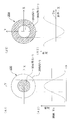
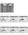
- FIG. 22 shows an example of a captured image and a histogram before correction.
- a photographed image F3B photographed by projecting the projection target image F1 onto the measurement object 2 colored in FIG. 22A is shown in FIG. 22B, and this photographed image F3B is shown in two regions “(a)” in FIG.
- the area is divided into “region” (left half) and “(b) region” (right half). Comparing the colors of the area (a) and the area (b), the area (a) is bluish but relatively brightly colored, and the color of the color code target CT is easy to distinguish. On the other hand, the area (b) is greenish and is relatively darkly colored, and it is difficult to determine the color of the color code target CT.
- FIG. 22 shows an example of a captured image and a histogram before correction.
- FIG. 22C shows a red, green, and blue histogram in the area (a)
- FIG. 22D shows a red, green, and blue histogram in the area (b).
- the horizontal axis of the histogram is brightness (high on the right).
- the histogram is created by the histogram creation unit 65, and the created histogram is stored in the histogram storage unit 56.
- the histogram is simple, sharp, bright, and highly saturated, it is easy to determine the color, and when it is complex, broad, dark, and lowly saturated, it is difficult to determine the color.
- the spectrum distribution width of the (b) region is somewhat narrower (standard deviation is smaller) in red, green and blue than the (a) region. This corresponds to the ease of determining the color of the color code target CT in the captured image.
- FIG. 23 shows an example of a corrected photographed image and histogram.
- FIG. 23A shows a photographed image F3B photographed by projecting the corrected projection target image F4 onto the measurement object 2 colored
- FIG. 23A shows two photographed images F3B.
- a region “(a ′) region” (left half) and a “(b ′) region” (right half) are shown.
- the (a ′) region and the (b ′) region are after the correction of the (a) region and the (b) region, respectively. Comparing the colors of the (a ′) area and the (b ′) area, the (a ′) area is bluish like the (a) area, but is relatively brightly colored, and the color of the color code target CT is Easy to distinguish.
- FIG. 23B shows a red, green, and blue histogram in the area (a ′)
- FIG. 23C shows a red, green, and blue histogram in the area (b ′).
- the horizontal axis of the histogram is brightness (high on the right).
- the histogram is created by the histogram creation unit 65, and the created histogram is stored in the histogram storage unit 56.
- the spectrum distribution width (standard deviation) of each of red, green, and blue is somewhat smaller in the (a ′) region. This corresponds to the fact that the CT color is somewhat easier to distinguish. Further, comparing the histograms of the (b) region and the (b ′) region, the spectrum distribution width (standard deviation) of all of red, green, and blue is small in the (b ′) region, and the color code target This corresponds to the fact that the CT color is somewhat easier to distinguish.
- the histogram is observed, for example, correction is omitted when the distribution width (standard deviation) of the histogram spectrum is small, and correction is performed when the distribution width (standard deviation) of the histogram spectrum is large.
- a threshold is provided for the spectrum distribution width (standard deviation) in each of the red, green, and blue histograms, and correction is performed when the threshold is exceeded.
- the area (a) is not corrected, and the area (b) is corrected.
- a negative image or a complementary color image can be used for the correction. If a significant difference is also found in other characteristics of the histogram, such as variance, average value, median value, etc., the correctness of correction may be determined based on such characteristics.
- a reference color portion P2 is selected for a captured image obtained by selecting a reference color code target from the color code target CT of the projection target image F1 and projecting the reference color code target onto a white screen to capture a target image.
- the histogram of each unit area in the color code part P3 is stored in advance in the histogram storage part 56 as a reference histogram.
- the histogram creation unit 65 uses the histogram of each unit area in the reference color part P2 and the color code part P3 as a measurement histogram. create.
- the histogram calculation unit 86 compares the measurement histogram created by the histogram creation unit 65 with the reference histogram stored in the histogram storage unit 56, and calculates the difference between the measurement histogram and the reference histogram. For a color that is one of the characteristics of the color code target CT, for example, when the difference calculated by the histogram calculation unit 86 is large, correction is performed assuming that the predetermined allowable condition is not satisfied, and when the difference is small The correction is not performed on the assumption that a predetermined allowable condition is satisfied. For example, a threshold may be provided for the sum (absolute value) of absolute values of differences between the measurement histogram and the reference histogram, and correction may be made when the threshold is exceeded.
- the reference color of the color code target CT of the captured image F3 and the histogram of each code color can be brought close to the reference histogram. Therefore, for each color code unit area, the color code can be easily determined by determining the color code by using the reference color and the code color including the histogram from which the spectral components are removed.
- a reference projection target image is selected from the projection target images F1, and a histogram related to the color of a captured image obtained by projecting the reference projection target image onto a white screen to capture a target image is used as a reference histogram.
- This is stored in advance in the histogram storage unit 56.
- a histogram related to a selected region in the captured image may be stored in addition to the reference histogram.
- the histogram creation unit 65 creates a histogram of the captured image F3 as a measurement histogram.
- a histogram relating to the entire captured image F3 may be created as a measurement histogram, or a histogram relating to a selected part of the area in the captured image F3 may be created as a measurement histogram.
- the histogram calculation unit 86 compares the measurement histogram created by the histogram creation unit 65 with the reference histogram stored in the histogram storage unit 56, and calculates the difference between the measurement histogram and the reference histogram.
- correction is performed assuming that the predetermined allowable condition is not satisfied, and when the difference is small The correction is not performed on the assumption that a predetermined allowable condition is satisfied.
- a negative target image or a complementary color image is used in the region to form a projection target image F1 and a composite image F4.
- the discrimination of the color code can be facilitated.
- it may be determined whether the correction is appropriate or not using the threshold value of the histogram characteristic.
- FIG. 24 shows an example of correction processing of the target image F1 using a histogram.
- the process from the projection of the projection target image F1 (S120) to the detection of the color code target CT (S140) is the same as the example of the target image correction process of FIG.
- a histogram related to the color of the reference color code target is stored in advance in the histogram storage unit 56 as a reference histogram (S142).
- the histogram creation unit 65 creates a histogram relating to the color of the color code target CT in the captured image F3 as a measurement histogram (S144).
- the histogram calculator 86 obtains a difference between the measurement histogram and the reference histogram (S146).
- the histogram calculation unit 86 uses the reference of the color code target CT stored in the histogram storage unit 56. The difference from the reference histogram of each unit area of the color part P2 is calculated. If the measurement histogram created by the histogram creation unit 65 is a histogram of the entire reference color portion P2 of the color code target CT, the histogram calculation unit 86 uses the reference color of the color code target CT stored in the histogram storage unit 56. The difference from the reference histogram of the entire part P2 is calculated.
- the histogram calculation unit 86 calculates a difference from the reference histogram of the color code target CT stored in the histogram storage unit 56. . If the measurement histogram created by the histogram creation unit 65 is a histogram of the entire projection target image, the histogram calculation unit 86 calculates the difference from the reference histogram of the entire projection target image stored in the histogram storage unit 56. Calculate. If the measurement histogram created by the histogram creation unit 65 is a histogram of the selected region of the projection target image, the histogram calculation unit 86 selects the projection target image stored in the histogram storage unit 56. The difference from the reference histogram of the area is calculated.
- the allowable condition determination unit 7 determines whether or not the color code target CT in the captured image F3 satisfies a predetermined allowable condition based on the histogram difference obtained by the histogram calculation unit 86 (S150). . If the difference between the measurement histogram calculated by the histogram calculation unit 86 and the reference histogram is large, the color of the color code target CT in the projection target F1 is corrected, and if the difference is small, no correction is performed.
- a threshold is provided for the sum (integral value) of absolute values of differences, and if this sum is equal to or less than the threshold, it is determined that a predetermined allowable condition is satisfied, and if the total exceeds a threshold, it is determined that the predetermined allowable condition is not satisfied.
- the color of the color code target CT of the image F1 is corrected (S160).
- the device configuration is the same as in Example 3.
- the process is the same as in the third embodiment up to the calculation of the difference image F3C between the two captured images F3A and F3B in the image calculation unit 85, or the synthesis of the projection target image F1 and the negative image or the complementary color image F3D.
- the subsequent steps are different. That is, the difference image F3C or the composite image F4 is used as a captured image F6, and the color code target CT is detected using the captured image F6.
- the difference image F3C or the composite image F4 has a color that is easier to discriminate than the photographed image F3B that is photographed by projecting the projection target image F1 onto the measurement target 2 (background) to which the color is applied. By using the color code, it is easy, efficient and reliable to distinguish the color code.
- the difference image F3C described in the third embodiment is used, it is easier to determine the color of the color code target than the captured image F3B. Therefore, the difference image F3C (FIG. 17C) created in the third embodiment may be used as it is for detecting the color code target CT.
- the detection and code discrimination of the color code target CT are the same as the detection and code discrimination of the color code target in the first embodiment.
- the projection target image F1 is corrected using the negative image or the complementary color image F3D.
- the color of the color code target can be easily determined from the captured image F1 using the negative image or the complementary color image.
- the R, G, and B components in the RGB color space of each pixel of the negative image or the complementary color image are photographed as A ′ (R), A ′ (G), A ′ (B), and the target image F2 is photographed.
- the corrected photographed image F6 can be obtained by synthesis.
- Use of the corrected captured image F6 makes it easier to determine the color of the color code target as compared to the original captured image F3B.
- the color code target detection and code discrimination are the same as the color code target detection and code discrimination in the first embodiment.
- FIG. 25 shows an example of color code target detection.
- the process from the white image projection (S410) to the step of obtaining the negative image or complementary color image of the captured image F3A (S455) is the same as the flow of the correction process (see FIG. 19) of the projection target image F1 of the third embodiment.
- the negative image or the complementary color image F3D (FIG. 18A) is synthesized with the captured image F3B (FIG. 17B) obtained by projecting the projection target image F1 onto the measurement target 2 to which the color is applied.
- a new target detection image F7 is created (S465) As the new target detection image F7, for example, an image as shown in Fig. 17C or Fig. 18B is obtained.
- the negative image or the complementary color image F3D the color applied to the measurement object 2 is well canceled out, and the color of the color code target CT close to the original color is obtained.
- the allowable condition determination unit 7 determines whether or not the color code target CT in the new target detection image F7 satisfies a predetermined allowable condition (S490). If the color code target CT in the new target detection image F7 does not satisfy the predetermined permissible condition (No in S490), the process returns to (S455), and a new negative image or complementary color image is created to detect the target. The image F7 is created again. Specifically, a negative image or a complementary color image of a portion that has not been canceled is created and combined with a new target detection image F7.
- the target position detection unit 51 detects the color code target CT from the target detection image F7. (S500).
- the subsequent steps are the same as the flow of the correction process for the projection target image F1 of the third embodiment.
- the result of the calculation of removing the spectral component not in the reference histogram from the measurement histogram in the histogram calculation unit 86 of the image processing unit 8 is reflected in the photographed image F6, and the detection of the color code target and the code determination are performed. You may use for.
- the apparatus configuration in this case is the same as that of the fourth embodiment.
- the apparatus configuration in the present embodiment may be a configuration obtained by removing the image processing unit 8 from the configuration in the first embodiment.
- the projection condition setting unit 31 in the projection unit 3 sets projection conditions (magnification, illumination intensity, angle of view, projection direction, etc.) in advance, and the projection conditions The projection target image is projected using the projection conditions set by the setting unit 31.
- the target image F2 projected on the measurement object 2 is captured to obtain a captured image F3, the target is detected by the target feature detection unit 62, and the captured image F3 is detected by the allowable condition determination unit 7.
- the projection condition setting unit 31 changes the projection condition so that the captured image F3 satisfies the predetermined allowable condition. And reset.
- the predetermined allowable conditions include, for example, target dimensions (for example, retro target dimensions within 10 to 18 pixels), light intensity (for example, about 300 (low value for office lighting) to 30,000 (low value for direct sunlight) lux ), A condition related to the inclination of the target (for example, the inclination with respect to the optical axis is within 30 degrees). If the projected image F3 can satisfy a predetermined allowable condition if the projection condition is changed, it is easier to change the projection condition than to correct the projection target image F1, so this Is preferably used. In addition, a change in target characteristics and a change in projection conditions may be used in combination. That is, the correction of the projection target image by changing the target characteristics and the change of the projection conditions may be used together.
- target dimensions for example, retro target dimensions within 10 to 18 pixels
- light intensity for example, about 300 (low value for office lighting) to 30,000 (low value for direct sunlight) lux
- a condition related to the inclination of the target for example, the inclination with respect to the optical axi
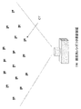
- FIG. 26 shows an example of projection by the projection device 1W with an ultra-wide angle lens.
- a projection apparatus with an ultra-wide-angle lens An example in which projection is performed by a projection apparatus with an ultra-wide-angle lens will be described.
- One projection target image F1 in which a large number of color code targets CT are arranged can be projected onto a vast range of a vast measurement object 2 using an ultra-wide-angle lens.
- the measurement object 2 is vast, it is preferable to project using a wide-angle lens because the surface of the measurement object 2 can be widely covered with one projection.
- the apparatus configuration is different from the first to sixth embodiments in that the projection unit 3 uses an ultra-wide-angle lens, but there is no other difference, and the correction processing flow of the projection target image F1 is the first to the sixth embodiments.
- the processing flow similar to 6 can be applied.
- the target projected in a direction away from the optical axis is distorted in shape due to projective distortion. Therefore, as described for the projection target image F1, as described in the first embodiment, a target separated from the optical axis by editing or forming the projection target image F4 in which the projection distortion is corrected with respect to the characteristics (here, the shape) of the target. With respect to the target image F2, the projection distortion is corrected. Therefore, the target whose projection distortion is corrected can be detected in the captured image F3. Further, from the beginning, a projection target image F4 in which the projection distortion is corrected may be prepared, and the target may be detected using the captured image F3 of the target video F2.
- the projection distortion due to the super-wide-angle lens is corrected and projected, which is convenient for wide-area three-dimensional measurement.
- both are target feature changes, but the target feature change and projection distortion correction described in the first embodiment may be used in combination.
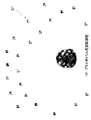
- FIG. 27 shows an example of projection by the planetarium type projector 1P.
- the eighth embodiment an example of projecting with a planetarium type projector will be described.
- a large number of different projection target images F1 are prepared, and each projection target image F1 is projected in a different direction (angle) using a projection lens. It is suitable for the ring-shaped measuring object 2 and the hemispherical measuring object 2.
- the configuration of the apparatus is different from that of the first to sixth embodiments in that a planetarium type projection device is used in the projection unit 3 and a large number of projection lenses and a projection target image F1 are used.
- the same process flow as in the first to sixth embodiments can be applied.
- FIG. 28 shows an example of shooting with the stereo camera 4A.
- a stereo camera 4A is used for the imaging unit 4
- the three-dimensional measurement it is necessary to photograph each measurement point of the measurement object 2 with at least two cameras.
- the left image and the right image captured by the left and right cameras are mostly overlapped, which is suitable for obtaining three-dimensional data.
- the overlapping area of a pair of stereo images is photographed so as to overlap with the overlapping area of adjacent stereo images and the captured images are connected, it is possible to cover and acquire all the vast entire images.
- the baseline length is the same for different stereo images, a unified corresponding point search can be performed.
- the same processing flow as in the first to sixth embodiments can be applied to the correction processing flow of the projection target image F1.
- the liquid crystal type (transmission type, reflection type) display image has been described as the projection target image.
- a CRT screen or a DLP type display screen is displayed. It may be used.
- a color code target in which a retro target is arranged in three corners as a target has been described as a target.
- other shapes such as a circular shape and an annular shape may be used.
- a target group other than a color code target for example, a target group arrangement in which three or more retro targets are combined, if the shape, size, and position are inappropriate, the correction can be applied.
- the present invention can be applied to the correction of the shape, size, and position with respect to the arrangement of target groups in which a plurality of color code targets and a plurality of retro targets are combined.
- target shape correction an example in which the linear deformation of the shape is corrected by the projective transformation has been described.
- the curved surface deformation for example, it is divided into fine sections and corrected and synthesized by the projective transformation. May be.
- the RGB color space and the HSI color space have been described as the color spaces for performing image processing, other color spaces such as a YCC color space, a YUV color space, and an XYZ color space may be used.
- extraction of inappropriate areas may be performed automatically with a predetermined margin
- a shooting condition setting unit is provided in the shooting unit to automatically adjust shooting conditions.
- either the projection and photographing of the projection white image and the projection and photographing of the projection target image may be performed first.
- the range of allowable conditions can be arbitrarily selected according to the situation.
- the present invention is used for three-dimensional measurement.
- it is suitable for three-dimensional measurement that requires a large number of targets, such as a vast object or a complex object.
Landscapes
- Engineering & Computer Science (AREA)
- Physics & Mathematics (AREA)
- General Physics & Mathematics (AREA)
- General Engineering & Computer Science (AREA)
- Theoretical Computer Science (AREA)
- Computer Vision & Pattern Recognition (AREA)
- Length Measuring Devices By Optical Means (AREA)
- Image Processing (AREA)
- Projection Apparatus (AREA)
Abstract
測定対象に投影されたターゲットが検出し難い場合に、投影用ターゲット画像を補正して、再度投影できるターゲット投影装置を提供する。 ターゲットTが表示された投影用ターゲット画像F1を測定対象2に投影する投影部3、投影部3から投影用ターゲット画像F1を投影して測定対象2に映されたターゲット映像F2を撮影して撮影画像F3を得る撮影部4、撮影部4で撮影された撮影画像F3からターゲットTの特徴を検出するターゲット特徴検出部62、撮影画像F3におけるターゲットTの特徴に関する所定の許容条件を記憶する許容条件記憶部54、撮影画像F3が所定の許容条件を満たすか否かを判定する許容条件判定部7、許容条件判定部7が所定の許容条件を満たさないと判定した場合には、所定の許容条件を満たすようにターゲットTの特徴を変更して投影用ターゲット画像F1を補正する画像処理部8とを備える。
Description
本発明は、ターゲット投影装置及びターゲット投影方法に関する。詳しくは、ターゲットが表示された投影用ターゲット画像について、測定対象に投影されたターゲットが判別し易いように修正して投影可能なターゲット投影装置及び修正して投影するターゲット投影方法に関する。
従来は、測定対象にターゲットを貼付け、カメラで撮影して測定対象の三次元形状計測や三次元計測が行なわれていた。これに対して、発明者達は、広範囲の領域にわたる測定対象に効率良く三次元計測を行うために、ターゲットを貼付することなく、ターゲット画像を測定対象に投影して計測を行う、三次元計測用投影装置を提案した。これにより、計測の効率が向上し、計測の自動化が促進された。(特許文献1,2参照)
しかしながら、測定対象に投影されたターゲットの形状が、測定対象の傾斜や起伏により変形される場合がある。また、測定対象との距離により、ターゲットが大きく映る場合、小さく写る場合もある。また、ターゲットの位置が、測定対象の起伏の激しい領域、光が当たらない暗い領域、黒色に近い低明度の色彩が着色されている領域、光が反射されて見え難い領域等、ターゲットの検出に不適当な位置になる場合がある。また、ターゲットの色彩が背景となる測定対象の色彩により見え難い場合がある。このように、測定対象に投影されたターゲットが検出し難い場合がある。
本発明は、測定対象に投影されたターゲットが検出し難い場合に、投影用ターゲット画像におけるターゲットの形状、寸法、位置、色彩等の特徴を検出し易いように補正して、再度投影できるターゲット投影装置及びターゲット投影方法を提供することを目的とする。
上記課題を解決するために、本発明の第1の態様に係るターゲット投影装置1は、例えば図1に示すように、ターゲットTが表示された投影用ターゲット画像F1を測定対象2に投影する投影部3と、投影部3から投影用ターゲット画像F1を投影して測定対象2に映されたターゲット映像F2を撮影して撮影画像F3を得る撮影部4と、撮影部4で撮影された撮影画像F3からターゲットTの特徴を検出するターゲット特徴検出部62と、撮影画像F3におけるターゲットTの特徴に関する所定の許容条件を記憶する許容条件記憶部54と、撮影画像F3におけるターゲットTが所定の許容条件を満たすか否かを判定する許容条件判定部7と、許容条件判定部7が所定の許容条件を満たさないと判定した場合には、所定の許容条件を満たすようにターゲットTの特徴を変更して投影用ターゲット画像F1を補正する画像処理部8とを備える。
ここにおいて、投影方式として、CRT方式、液晶方式(透過型、反射型)、DLP(デジタル・ライト・プロセッシング)方式等を使用可能である。これに対応して、投影用ターゲット画像F1として、CRT画面、液晶ディスプレイ画面、マイクロミラーによりモニタに投影される画面等を使用可能である。また、撮影画像におけるターゲットTの特徴として、ターゲットの形状、寸法、色彩、位置座標、回転角度等が挙げられ、ターゲットTが複数の場合には、ターゲットの数、ターゲットの配置等が挙げられる。また、所定の許容条件として、ターゲットの特徴についての条件(範囲等)が挙げられる。
本態様のように構成すると、ターゲットTが検出し難い場合に、投影用ターゲット画像F1におけるターゲットの形状、寸法、位置、色彩等の特徴を検出し易いように補正して、再度投影できるターゲット投影装置を提供できる。
本態様のように構成すると、ターゲットTが検出し難い場合に、投影用ターゲット画像F1におけるターゲットの形状、寸法、位置、色彩等の特徴を検出し易いように補正して、再度投影できるターゲット投影装置を提供できる。
また、本発明の第2の態様に係るターゲット投影装置1は、例えば図1に示すように、ターゲットTが表示された投影用ターゲット画像F1を測定対象2に投影する投影部3と、投影部3から投影用ターゲット画像F1を投影して測定対象2に映されたターゲット映像F2を撮影して第1の撮影画像F3Bを得、照明された測定対象2を撮影して第2の撮影画像F3Aを得る撮影部4と、測定対象2におけるターゲットTを投影するのに不適当な領域の条件を記憶する許容条件記憶部54と、不適当な領域の条件に基づいて第2の撮影画像F3Aから撮影対象2におけるターゲットを投影するのに不適当な領域を抽出する不適当領域抽出部63と、許容条件判定部7が不適当な領域を抽出した場合には、投影用ターゲット画像F1内のターゲットTが不適当な領域に投影されないようにターゲットTの特徴を変更して投影用ターゲット画像F1を補正する画像処理部8とを備える。
ここにおいて、通常は、第1の撮影画像F3BはターゲットTを含む撮影画像であり、第2の撮影画像F3AはターゲットTを含まない撮影画像である。照明として、投影部3から投影用白色画像F0(図示しない)を投影して照明とするのが、投影用ターゲット画像F1の投影と同じ投影条件で行なえるのでベターであるが、その他の照明光や太陽光による自然照明を用いても良い。また、不適当な領域として、低明度の領域(黒色及び黒色に近い色彩が着色されている領域、又は日影・日陰等の暗い領域)、光を反射する領域等が挙げられる。ここで、「反射」とは、正(鏡面)反射を意味する。「反射する領域」とは、反射光によって投影したターゲットが判別できないような反射率の高い領域が該当する。
本態様のように構成すると、ターゲットTが検出し難い不適当な領域にある場合に、投影用ターゲット画像F1におけるターゲットの位置を不適当な領域に投影されないように補正して、再度投影できるターゲット投影装置を提供できる。
本態様のように構成すると、ターゲットTが検出し難い不適当な領域にある場合に、投影用ターゲット画像F1におけるターゲットの位置を不適当な領域に投影されないように補正して、再度投影できるターゲット投影装置を提供できる。
また、本発明の第3の態様に係るターゲット投影装置は、第2の態様において、例えば図1に示すように、投影部3は投影用白色画像F0を測定対象2に投影することができ、撮影部4は投影用白色画像F0で照明された測定対象2を撮影して第2の撮影画像F3Aを得る。
ここにおいて、投影用白色画像F0は例えば液晶画面全体を白色に表示したものを使用できる。本態様のように構成すると、投影用ターゲット画像F1と投影用白色画像F0を同じ表示画面を用いて形成でき、便宜である。
ここにおいて、投影用白色画像F0は例えば液晶画面全体を白色に表示したものを使用できる。本態様のように構成すると、投影用ターゲット画像F1と投影用白色画像F0を同じ表示画面を用いて形成でき、便宜である。
また、本発明の第4の態様に係るターゲット投影装置は、第3の態様において、投影用白色画像F0は投影用ターゲット画像F1と同じ投影条件で照射される。
このように構成すると、投影用ターゲット画像F1と投影用白色画像F0の差画像や合成画像を作成する処理が効率的で容易になる。
このように構成すると、投影用ターゲット画像F1と投影用白色画像F0の差画像や合成画像を作成する処理が効率的で容易になる。
また、本発明の第5の態様に係るターゲット投影装置は、第1ないし第4のいずれかの態様において、ターゲットTの特徴は、ターゲットTの形状、寸法、色彩、位置座標、回転角度、ターゲットTが複数の場合の数、配置の少なくとも1つを含む。
また、本発明の第6の態様に係るターゲット投影装置は、第1の態様において、所定の許容条件は、ターゲットTの特徴(ターゲットの形状、寸法、色彩、位置座標、回転角度、ターゲットが複数の場合の数、配置、ターゲットと背景との関係等)に関する条件(範囲等)である。
このように構成すると、ターゲットTの特徴を補正して、ターゲットTを検出し易くできる。
このように構成すると、ターゲットTの特徴を補正して、ターゲットTを検出し易くできる。
また、本発明の第7の態様に係るターゲット投影装置1は、第2の態様において、不適当な領域は、例えば図10又は図11に示すように、低明度の領域又は光を反射する領域である。
ここにおいて、低明度の領域として、黒色及び黒色に近い色彩が着色されている領域、日陰や日影等の暗い領域が挙げられる。このように構成すると、ターゲットTが低明度の領域又は光を反射する領域に投影されないように補正して、ターゲットTを検出し易くできる。
ここにおいて、低明度の領域として、黒色及び黒色に近い色彩が着色されている領域、日陰や日影等の暗い領域が挙げられる。このように構成すると、ターゲットTが低明度の領域又は光を反射する領域に投影されないように補正して、ターゲットTを検出し易くできる。
また、本発明の第8の態様に係るターゲット投影装置1は、第1ないし第7のいずれかの態様において、例えば図1及び図2に示すように、ターゲットTとしてカラーコードターゲットCTを使用でき、ターゲット検出部6は、撮影画像F3からカラーコードターゲットCTの位置検出用パターン及びコード識別用のカラーコードパターンを検出する。
ここにおいて、カラーコードターゲットCTとは、個別のターゲットがカラーコードの配色により識別可能なターゲットをいう。このように構成すると、カラーコードターゲットCTを使用すると各ターゲットを識別できるので、三次元計測を高信頼度で効率的に行うことができる。
ここにおいて、カラーコードターゲットCTとは、個別のターゲットがカラーコードの配色により識別可能なターゲットをいう。このように構成すると、カラーコードターゲットCTを使用すると各ターゲットを識別できるので、三次元計測を高信頼度で効率的に行うことができる。
また、本発明の第9の態様に係るターゲット投影装置1Bは、第1の態様において、例えば図21に示すように、ターゲットTとしてカラーコードターゲットCTを使用でき、基準のカラーコードターゲットの色彩に係るヒストグラムを基準ヒストグラムとして記憶するヒストグラム記憶部56と、撮影画像F3におけるカラーコードターゲットCTの色彩に係るヒストグラムを測定ヒストグラムとして作成するヒストグラム作成部65と、測定ヒストグラムと基準ヒストグラムとの差異を求めるヒストグラム演算部86とを備え、許容条件判定部7がヒストグラム演算部86で求められたヒストグラムの差異に基づいて、撮影画像F3におけるカラーコードターゲットCTが所定の許容条件を満たすか否かを判定し、画像処理部8は、許容条件判定部7にて所定の許容条件を満たさないと判定されたカラーコードターゲットCTについて、所定の許容条件を満たすように投影用ターゲット画像F1のカラーコードターゲットCTの色彩を補正する。
ここにおいて、基準のカラーコードターゲットは使用者が選定できる。例えば、カラーコードターゲットCT単体からなる特定の投影用ターゲット画像F1を基準のカラーコードターゲットとして選定できる。この場合、選定された基準のカラーコードターゲットを白色のスクリーンに投影し、そのターゲット映像F2を撮影した撮影画像F3のカラーコードターゲットCTの色彩に係るヒストグラムが基準のカラーコードターゲットの色彩に係るヒストグラムとして採用される、また、例えば、特定の投影用ターゲット画像F1から特定のカラーコードターゲットCTを選定しても良い。この場合、選定された特定の投影用ターゲット画像F1を白色のスクリーンに投影し、そのターゲット映像F2を撮影した撮影画像F3における特定のカラーコードターゲットCTの色彩に係るヒストグラムが基準のカラーコードターゲットの色彩に係るヒストグラムとして採用される。また、基準のカラーコードターゲットCTの色彩に係るヒストグラムとして、カラーコードターゲットCT全体に係るヒストグラムを使用しても良く、基準色部P2の各単位領域に係るヒストグラム、カラーコード部P3の各単位領域に係るヒストグラムを使用しても良く、また、カラーコードターゲットCTの一部、例えば基準色部P2に係るヒストグラムを使用しても良い。
本態様のように構成すると、ヒストグラムを用いて高精度にターゲットの補正の是非を判断することができる。
本態様のように構成すると、ヒストグラムを用いて高精度にターゲットの補正の是非を判断することができる。
また、本発明の第10の態様に係るターゲット投影装置は、第1の態様において、例えば図22及び図23に示すように、撮影画像F3の色彩に係るヒストグラムを測定ヒストグラムとして作成するヒストグラム作成部65を備え、許容条件記憶部54は撮影画像F3の色彩に係るヒストグラムの特性に関する所定の許容条件を記憶し、許容条件判定部7がヒストグラム作成部65で作成された測定ヒストグラムの特性に基づいて、撮影画像F3内の選択された領域が所定の許容条件を満たすか否かを判定し、画像処理部8は、許容条件判定部7にて所定の許容条件を満たさないと判定された領域において、所定の許容条件を満たすように投影用ターゲット画像F1の色彩を補正する。
ここにおいて、ヒストグラムの特性として、例えばヒストグラムの標準偏差、分散、平均値、中央値等が挙げられる。また、ヒストグラムとして、撮影画像F3全体に係るヒストグラムを使用しても良く、撮影画像F3内の選択された一部の領域に係るヒストグラムを使用しても良い。また、選択された領域は撮影画像全体でも良い。
本態様のように構成すると、ヒストグラムを用いて高精度にターゲットの補正の是非を判断することができる。
本態様のように構成すると、ヒストグラムを用いて高精度にターゲットの補正の是非を判断することができる。
また、本発明の第11の態様に係るターゲット投影装置は、第1ないし第10のいずれかの態様において、撮影部4はステレオカメラを有し、撮影画像F3はステレオ画像で構成される。
このように構成すると、ステレオカメラを用いて同じ基線長の重複画像を系統的に撮影できるので、三次元計測に好適である。
このように構成すると、ステレオカメラを用いて同じ基線長の重複画像を系統的に撮影できるので、三次元計測に好適である。
また、本発明の第12の態様に係るターゲット投影装置1Wは、第1又は第2の態様において、例えば図26に示すように、投影部3は超広角レンズを用いて投影用ターゲット画像F1を投影し、画像処理部8は、投影光軸から離れたターゲットTについて射影歪が補正されるようにターゲットTの特徴を変更して投影用ターゲット画像F1を編集する。
このように構成すると、編集された投影用ターゲット画像F4を用いると、超広角レンズによる射影歪が補正されて投影されるので、広域の三次元計測に便宜である。
このように構成すると、編集された投影用ターゲット画像F4を用いると、超広角レンズによる射影歪が補正されて投影されるので、広域の三次元計測に便宜である。
また、本発明の第13の態様に係るターゲット投影装置1Wは、第1又は第2の態様において、例えば図26に示すように、投影部3は超広角レンズを用いて投影用ターゲット画像F1を投影し、投影用ターゲット画像F1において、投影光軸から離れたターゲットTについて射影歪が補正されるように形成されている。
このように構成すると、形成された投影用ターゲット画像F4を用いると、超広角レンズによる射影歪が補正されて投影されるので、広域の三次元計測に便宜である。
このように構成すると、形成された投影用ターゲット画像F4を用いると、超広角レンズによる射影歪が補正されて投影されるので、広域の三次元計測に便宜である。
また、本発明の第14の態様に係るターゲット投影装置1Pは、第1ないし第10のいずれかの態様において、例えば図27に示すように、投影部3はプラネタリウム型投影装置を用いて複数の投影用ターゲット画像F1像を同時に投影する。
このように構成すると、円筒状又は球状の測定対象の計測に好適である。
このように構成すると、円筒状又は球状の測定対象の計測に好適である。
また、本発明の第15の態様に係るターゲット投影装置は、第1ないし第10のいずれかの態様において、画像処理部8で編集された投影用ターゲット画像F1を測定対象2に投影して撮影部4で撮影された2以上の撮影画像F3から、ターゲット特徴検出部62で検出されたターゲットTの位置座標に基づいて、測定対象2の形状又は投影部3の位置座標を求める三次元座標演算部13を備える。
このように構成すると、検出されたターゲットTの位置座標を用いて、同じ装置で即三次元計測ができ便宜である。
このように構成すると、検出されたターゲットTの位置座標を用いて、同じ装置で即三次元計測ができ便宜である。
上記課題を解決するために、本発明の第16の態様に係るターゲット投影方法は、例えば図10に示すように、ターゲットTが表示された投影用ターゲット画像F1を測定対象2に投影する第1の投影工程(S120)と、第1の投影工程(S120)で投影用ターゲット画像F1を投影して測定対象2に映されたターゲット映像F2を撮影して撮影画像F3を得る撮影工程(S130)と、撮影工程(S130)で撮影された撮影画像F3からターゲットTの特徴を検出するターゲット特徴検出工程(S140)と、撮影画像F3が所定の許容条件を満たすか否かを判定する許容条件判定工程(S150)と、許容条件判定工程(S150)で所定の許容条件を満たさないと判定された場合には、所定の許容条件を満たすようにターゲットの特徴Tを変更して投影用ターゲット画像F1を補正するターゲット画像補正工程(S160)と、ターゲット画像補正工程(S160)で補正された投影用ターゲット画像F4を測定対象2に投影する第2の投影工程(S170)とを備える。
本態様は第1の態様に係るターゲット投影装置1に対応するターゲット投影方法の態様である。本態様のように構成すると、ターゲットTが検出し難い場合に、投影用ターゲット画像F1におけるターゲットの形状、寸法、位置、色彩等の特徴を検出し易いように補正して、再度投影できるターゲット投影方法を提供できる。
また、本発明の第17の態様に係るターゲット投影方法は、例えば図13に示すように、照明された測定対象2を撮影して第2の撮影画像F3Aを得る第2の撮影工程(S115)と、測定対象2におけるターゲットTを投影するのに不適当な領域の条件を記憶する許容条件記憶工程(S105)(図示しない)と、不適当な領域の条件に基づいて第2の撮影画像F3Aから撮影対象2におけるターゲットTを投影するのに不適当な領域を抽出する不適当領域抽出工程(S132)と、不適当領域抽出工程(S132)で不適当な領域が抽出された場合には、投影用ターゲット画像F1内のターゲットTが不適当な領域に投影されないようにターゲットTの特徴を変更して投影用ターゲット画像F1を補正するターゲット画像補正工程(S165)と、ターゲット画像補正工程(S165)で補正された投影用ターゲット画像F1を測定対象2に投影する第2の投影工程(S170)とを備える。
本態様は第2の態様に係るターゲット投影装置1に対応するターゲット投影方法の態様である。本態様のように構成すると、ターゲットTが検出し難い不適当な領域にある場合に、投影用ターゲット画像F4におけるターゲットTの位置を不適当な領域に投影されないように補正して、再度投影できるターゲット投影方法を提供できる。
本発明によれば、測定対象に投影されたターゲットが検出し難い場合に、投影用ターゲット画像におけるターゲットの形状、寸法、位置、色彩等の特徴を検出し易いように補正して、再度投影できるターゲット投影装置及びターゲット投影方法を提供できる。
この出願は、日本国で2010年3月31日に出願された特願2010-084528号に基づいており、その内容は本出願の内容として、その一部を形成する。本発明は以下の詳細な説明によりさらに完全に理解できるであろう。本発明のさらなる応用範囲は、以下の詳細な説明により明らかとなろう。しかしながら、詳細な説明及び特定の実例は、本発明の望ましい実施の形態であり、説明の目的のためにのみ記載されているものである。この詳細な説明から、種々の変更、改変が、本発明の精神と範囲内で、当業者にとって明らかであるからである。出願人は、記載された実施の形態のいずれをも公衆に献上する意図はなく、改変、代替案のうち、特許請求の範囲内に文言上含まれないかもしれないものも、均等論下での発明の一部とする。
以下、図面を参照して、本発明の実施の形態について説明する。尚、各図において、互いに同一又は相当する部分には同一符号を付し,重複した説明は省略する。
以下、図面を参照して、本発明の実施の形態について説明する。尚、各図において、互いに同一又は相当する部分には同一符号を付し,重複した説明は省略する。
実施例1では、ターゲットが表示された投影用ターゲット画像を測定対象に投影し、投影されたターゲット画像(以下、投影用ターゲット画像と区別するために、ターゲット映像という。)を撮影して得られた撮影画像において、ターゲットが所定の許容条件を満たさない場合には、所定の許容条件を満たすように投影用ターゲット画像を補正する例について説明する。
[装置構成]
図1に実施例1におけるターゲット投影装置1の構成例を示す。ターゲット投影装置1は、投影部3、撮影部4、記憶部5、ターゲット検出部6、許容条件判定部7、画像処理部8、制御部9、表示部11、入力部12を備える。2は測定対象である。このうち、ターゲット検出部6、許容条件判定部7、画像処理部8及び制御部9はパーソナルコンピュータ(PC)10で実現可能であり、PC10内に設けられる。
測定対象2は土地、建物、製品、美術品等、三次元形状や三次元座標等の三次元計測の対象物である。従来は、カラーコードターゲット等のターゲットを測定対象2に貼り付けて、ターゲットの位置を検出し、三次元計測に使用していたが、本実施例では、カラーコードターゲット等のターゲットTを測定対象2に投影し、三次元計測に使用する。
ターゲットTとして、通常はレトロターゲットが使用されるが、識別コードが付与されたコードターゲットを使用すると測定を高信頼かつ迅速に実施でき好適である。本実施例では主として識別コードに色彩を採用したカラーコードターゲット(例えば、特開2007-101277号公報参照)を使用する。
図1に実施例1におけるターゲット投影装置1の構成例を示す。ターゲット投影装置1は、投影部3、撮影部4、記憶部5、ターゲット検出部6、許容条件判定部7、画像処理部8、制御部9、表示部11、入力部12を備える。2は測定対象である。このうち、ターゲット検出部6、許容条件判定部7、画像処理部8及び制御部9はパーソナルコンピュータ(PC)10で実現可能であり、PC10内に設けられる。
測定対象2は土地、建物、製品、美術品等、三次元形状や三次元座標等の三次元計測の対象物である。従来は、カラーコードターゲット等のターゲットを測定対象2に貼り付けて、ターゲットの位置を検出し、三次元計測に使用していたが、本実施例では、カラーコードターゲット等のターゲットTを測定対象2に投影し、三次元計測に使用する。
ターゲットTとして、通常はレトロターゲットが使用されるが、識別コードが付与されたコードターゲットを使用すると測定を高信頼かつ迅速に実施でき好適である。本実施例では主として識別コードに色彩を採用したカラーコードターゲット(例えば、特開2007-101277号公報参照)を使用する。
投影部3はターゲットTが表示された投影用ターゲット画像F1を測定対象2に投影する。投影方式として、CRT方式、液晶方式(透過型、反射型)、DLP(デジタル・ライト・プロセッシング)方式等を使用可能である。これに対応して、投影用ターゲット画像F1として、CRT画面、液晶ディスプレイ画面、マイクロミラーによりモニタに投影される画面等を使用可能である。本実施例では透過型又は反射型の液晶ディスプレイ画面を使用することとする。
投影部3で投影用ターゲット画像F1を測定対象2の表面に投影する。投影された投影用ターゲット画像をターゲット映像F2という。また、ターゲット映像F2を撮影したものを含め撮影した画像を撮影画像F3という。測定対象2の表面には凹凸、屈曲等の起伏があったり、日陰(光が直接当らない陰の領域)や日影(他の物体の影になる領域)等の暗い領域があったり、黒色に近い低明度の色彩(黒色を含むものとする)が着色されている領域、光が反射される領域があったりする。このような測定対象2の表面状態はターゲット映像F2に反映されて、ターゲット映像F2はこれらの領域で歪んだり、見え難くなる。したがって、これらの領域に投影用ターゲット画像F1に表示された各ターゲットTが投影されると、ターゲットTの検出やコード判別が難しくなる。これらの映像が歪んだり、見え難くなっており、ターゲットを投影するのに不適当な領域を不適当領域と称することとする。
投影部3は、投影条件を設定・調整するための投影条件設定部31を有する。投影条件設定部31では、倍率、照射光強度、投影角度等の設定と調整が可能である。したがって、最初の設定又は調整でターゲット映像F2や撮影画像F3が見え難い場合には、投影条件を再設定し又は再調整して再投影することが可能である。
撮影部4は単カメラ又はステレオカメラを有し、投影部3で測定対象2に投影されたターゲット映像F2を撮影して撮影画像F3を取得する。三次元計測にはターゲット映像F2の各領域を少なくとも二重に撮影する必要がある。したがって、ステレオカメラを使用すると、大部分の領域で重複した撮影画像が得られるので好ましい。単カメラを使用する場合には、ターゲット映像F2の全ての領域を少なくとも二回撮影するように、撮影位置を変え重複させながら撮影を行なう。測定対象2が広大な表面を有する場合には、複数の撮影画像を繋げて必要な全表面を得る。この場合、接続部分には少なくとも2以上のターゲットを含むようにする。撮影画像F3には、通常、カメラから見たターゲット映像F2の様相がそのまま反映されるので、ターゲット映像F2でターゲットの検出やコード判別が困難な場合には、撮影画像F3でもターゲットの検出やコード判別が困難となる。
記憶部5は投影用ターゲット画像F1を記憶する投影用ターゲット画像記憶部51、撮影画像F3を記憶する撮影画像記憶部52、検出された各ターゲットTの特徴を記憶するターゲット特徴記憶部53、撮影画像F3におけるターゲットTの特徴に関する所定の許容条件を記憶する許容条件記憶部54、補正後の投影用ターゲット画像F4を記憶する補正画像記憶部55を有する。
ターゲット検出部6は、撮影部4で撮影された撮影画像F3からターゲットTの位置を検出するターゲット位置検出部61、ターゲットTの特徴を検出するターゲット特徴検出部62、不適当領域を検出する不適当領域抽出部63、カラーコードターゲットの識別コードを判別するコード判別部64を有する。ターゲットTの検出は、通常レトロターゲットを検出して行なうが、カラーコードターゲットの場合は、例えば正方形のターゲットの3隅に配置されたレトロターゲットを検出して行なう。ターゲットTの特徴として、ターゲットTの形状、寸法、色彩、位置座標、回転角度等が挙げられ、ターゲットTが複数の場合には投影用ターゲット画像F1内のターゲット数、ターゲット配置等が挙げられる。検出されたターゲットTの特徴はターゲット特徴記憶部53に記憶される。
許容条件判定部7は、撮影画像F3におけるターゲットの特徴が所定の許容条件を満たすか否かを判定する。許容条件判定部7は、新たに撮影され、ターゲット特徴記憶部53に記憶された撮影画像F3におけるターゲットTの特徴を、許容条件記憶部54に記憶されたターゲットTの特徴に関する所定の許容条件と比較し、許容条件を満たすか否かを判定する。所定の許容条件は、撮影画像F3におけるターゲットの形状については、例えば、正方形からの歪みが、頂角が85~95度以内、辺の長さの偏差が5%以内を許容範囲とし、寸法については、例えば、撮影画像F3におけるレトロターゲットの寸法が10画素~18画素以内を許容範囲とし、撮影画像F3におけるターゲットの色彩については、例えば、基準色(赤、緑、青)について、明度の変化がHSI表色系(マンセル表色系)11段階表示で±2以内、色相の変化がHSI表色系で±30度以内(又は100段階表示で±10以内)を許容範囲とし、撮影画像F3における位置座標(写真座標)については、例えば、背景の明度がHSI表色系で5(白と黒の中間)以下の暗い位置、反射光が写る位置(ハレーションがある位置)、測定対象2のエッジや頂点にあるものを許容範囲外とし、撮影画像F3におけるターゲットの回転角度については、例えば±5度以内を許容範囲とする等である。また、ターゲットが複数の場合には、例えば、撮影画像F3におけるターゲット数が4~20以内を許容範囲とし、投影用ターゲット画像F1におけるターゲットの配置については、例えば、選択されたターゲット(端部にあるものを除く)について、投影用ターゲット画像F1内の他の3つのターゲットが形成する三角形内に当該ターゲットが入り、かつこれら3つのターゲットまでの距離が撮影画像F3の短辺長の2/3以下であることを許容範囲とする等である。
画像処理部8は、投影用ターゲット画像F1について画像変換、画像移動、色彩補正、ターゲットの追加・削除等の画像処理を行なう。操作者は表示部11のモニタ画面に表示された投影用ターゲット画像F1を見て、入力部12のマウスやキーボードで指示を入力し、画像の編集作業を行なうことが出来る。又は、画像処理部8内に記憶されたプログラムにより自動的に画像処理が行われる。画像処理部8は画像変換部81、画像移動部82、色彩補正部83及びターゲット追加削除部84を有する。
画像変換部81は、投影用ターゲット画像F1又は撮影画像F3において、射影変換、アフィン変換等の画像間の変換を行なう。また、画像の拡大・縮小を行なう。例えば、許容条件判定部7が所定の許容条件を満たさないと判定した場合に、投影用ターゲット画像F1におけるターゲットの形状、寸法を変換するために用いられる。
画像移動部82は、投影用ターゲット画像F1又は撮影画像F3において、ターゲットを移動する、回転する等、画像内容を維持したまま、その位置と傾きを変更する。例えば、許容条件判定部7が所定の許容条件を満たさないと判定した場合に、投影用ターゲット画像F1におけるターゲットの位置座標、回転角度を変更するために用いられる。
色彩補正部83は、投影用ターゲット画像F1又は撮影画像F3において、カラーコードターゲットCTのカラーコードパターンの色彩について、カラーコードターゲットCTの基準色パターンの色彩を基準にして補正する。カラーコードパターンの各色彩を本来の色彩に修正することにより、カラーコードパターンのコードが判別容易になる。また、背景の色彩について基準色パターンの色彩を基準にして補正することも可能である。
ターゲット追加削除部84は、投影用ターゲット画像F1又は撮影画像F3において、ターゲットTの追加、削除を行なう。ターゲットTの追加はターゲット画像記憶部51に記憶されたターゲット画像から選択して挿入しても良く、ターゲットの単位パターンを素材として組み合わせ、色彩を付する等により、ターゲットを生成しても良い。ターゲットの削除は、例えばターゲットを選択して「削除」命令を実行することにより行なわれる。
なお、操作者が画像処理部8の機能を用い、表示部11のモニタを見ながら補正処理することも可能であるが、画像処理部8のコンピュータ機能を用いて自動補正することも可能である。すなわち、まず、許容条件判定部7において、撮影画像記憶部52に記憶された撮影画像F3について、許容条件記憶部54を参照しながら許容条件を満足するか否かを判定し、次に、画像処理部8において、許容条件を満足しないターゲットについて許容条件を満足するように、ターゲットの特徴(形状、寸法、色彩、位置座標、回転角度等)を補正する。補正すべき特徴に応じて画像変換部81、画像移動部82、色彩補正部83及びターゲット追加削除部84にて補正する。補正の際にはある程度マージンを取って行なうことが好ましい。次に、投影用ターゲット画像F1の位置座標と撮影画像F3の位置座標との対応関係を示す表を作成し、撮影画像F3において補正されたターゲットについて、表で対応する投影用ターゲット画像F1の位置座標を求め、補正された投影用ターゲット画像F4を作成する。補正された投影用ターゲット画像F4は補正画像記憶部55に記憶される。
表示部11はモニタ画面を有し、処理に応じて、投影用ターゲット画像F1、撮影画像F3、補正後の投影用ターゲット画像F4等を表示する。
入力部12は、マウス及びキーボードを有し、ユーザが指示を入力できる。
制御部9は、ターゲット投影装置1及びその各部の信号及びデータの流れを制御して、ターゲット投影装置の機能を発揮できるようにする。
三次元座標演算部13は、測定対象2の各特徴点(ターゲットを含む)について三次元座標を演算する。
入力部12は、マウス及びキーボードを有し、ユーザが指示を入力できる。
制御部9は、ターゲット投影装置1及びその各部の信号及びデータの流れを制御して、ターゲット投影装置の機能を発揮できるようにする。
三次元座標演算部13は、測定対象2の各特徴点(ターゲットを含む)について三次元座標を演算する。
[カラーコードターゲット]
図2にカラーコードターゲットの例を示す。図2(a)はカラーコードの単位領域が3個、図2(b)は6個、図2(c)は9個のカラーコードターゲットである。図2(a)~(c)のカラーコードターゲットCT(CT1~CT3)は、位置検出用パターンから成るレトロターゲット部P1、基準色パターンから成る基準色部P2、カラーコードパターンから成るカラーコード部P3、例えば空パターンから成る白色部P4で構成されている。これら、レトロターゲット部P1、基準色部P2、カラーコード部P3、白色部P4はカラーコードターゲットCT1内の所定の位置に配置される。すなわち、基準色パターン、カラーコードパターン、空パターンは位置検出用パターンに対して所定の位置関係に配置される。
図2にカラーコードターゲットの例を示す。図2(a)はカラーコードの単位領域が3個、図2(b)は6個、図2(c)は9個のカラーコードターゲットである。図2(a)~(c)のカラーコードターゲットCT(CT1~CT3)は、位置検出用パターンから成るレトロターゲット部P1、基準色パターンから成る基準色部P2、カラーコードパターンから成るカラーコード部P3、例えば空パターンから成る白色部P4で構成されている。これら、レトロターゲット部P1、基準色部P2、カラーコード部P3、白色部P4はカラーコードターゲットCT1内の所定の位置に配置される。すなわち、基準色パターン、カラーコードパターン、空パターンは位置検出用パターンに対して所定の位置関係に配置される。
レトロターゲット部P1は、ターゲット自体の検出用、その重心検出用、ターゲットの傾斜検出用、ターゲット領域検出用として使用される。
基準色部P2は、照明やカメラ等の撮影条件による色のズレに対応するために、相対比較時の参照用、色ズレを補正するためのカラーキャリブレーション用として使用される。さらに、基準色部P2は、簡易な方法で作成されたカラーコードターゲットCTの色彩補正用として使用できる。例えば、色管理がなされていないカラープリンター(インクジェット・レーザー・昇華型等のプリンタ)で印刷したカラーコードターゲットCTを使用する場合は、使用プリンタ等で色彩に個体差が出るが、基準色部P2とカラーコード部P3の色を相対比較し補正することで、個体差の影響を押さえることができる。
カラーコード部P3は、その各単位領域への配色の組み合わせによってコードを表現する。コードに使用するコード色の数により表現可能なコード数が変化する。例えば、コード色数がnで単位領域数が3の場合、n×n×n通りのコードを表せる。信頼度を上げるため、他の単位領域に使用されている色を重複して使用しないという条件を課した場合でも、n×(n-1)×(n-2)通りのコードを表せる。そして、コード色数を増やせばコード数を増加できる。さらに、カラーコード部P3の単位領域の数とコード色数を等しくするという条件を課すと、全てのコード色がカラーコード部P3に使用されるため、基準色部P2との比較のみで無く、カラーコード部P3の各単位領域間で色を相対比較することにより、各単位領域の色彩を確認して識別コードを決定することができ、信頼性を上げることができる。さらに、各単位領域の面積を全て同じにする条件を追加すると、カラーコードターゲットCTを画像中から検出する際にも使用できる。これは、異なる識別コードをもつカラーコードターゲットCT間でも各色の占有する面積が同じになるため、カラーコード部P3全体からの検出光からはほぼ同様な分散値が得られるからである。また、単位領域間の境界は等間隔に繰り返され、明確な色彩差が検出されるので、このような検出光の繰り返しパターンからもカラーコードターゲットCTを画像中から検出することが可能である。
白色部P4は、カラーコードターゲットCTの傾斜検出用と色ズレのキャリブレーション用として使用する。カラーコードターゲットCTの四隅の内、一カ所だけレトロターゲットが配置されない箇所があり、これをカラーコードターゲットCTの傾斜検出用に使用できる。このように白色部P4はレトロターゲットと異なるパターンであれば良い。したがって、白色部には目視でコードを確認するための番号などの文字列を印刷しても良く、また、バーコード等のコード領域としても使用しても良い。さらに、検出精度を上げるために、テンプレートマッチング用のテンプレートパターンとして使用することも可能である。
[カラーコードターゲットの検出フロー]
次に、カラーコードターゲットの検出フローについて説明する。まず、撮影画像記憶部52から処理対象の撮影画像F3を抽出し、撮影画像F3からカラーコードターゲットCTを抽出する。カラーコードターゲットCTの抽出はターゲット位置検出部61にて行なわれる。探索方法として、(1)カラーコードターゲットCT中の位置検出用パターン(レトロターゲット)を探索する方法、(2)カラーコード部P3の色分散を検出する方法、あるいは(3)彩色された位置検出用パターンを用いる方法など種々の方法がある。
次に、カラーコードターゲットの検出フローについて説明する。まず、撮影画像記憶部52から処理対象の撮影画像F3を抽出し、撮影画像F3からカラーコードターゲットCTを抽出する。カラーコードターゲットCTの抽出はターゲット位置検出部61にて行なわれる。探索方法として、(1)カラーコードターゲットCT中の位置検出用パターン(レトロターゲット)を探索する方法、(2)カラーコード部P3の色分散を検出する方法、あるいは(3)彩色された位置検出用パターンを用いる方法など種々の方法がある。
(1)カラーコードターゲットCTにレトロターゲットが含まれている場合は、明度差が鮮明なパターンを使用するので、カメラの絞りを絞りフラッシュ撮影することにより、レトロターゲットのみが光った画像を取得でき、この像を2値化することにより簡単にレトロターゲットを検出できる。
図3はレトロターゲットを用いた重心位置検出の説明図である。ただし、レトロターゲットでなく、黒地に白の塗装で形成した白色円形のターゲットでも処理は同様である。図3の例ではレトロターゲットは2つの同心円で形成されているが、外側が必ずしも円でなくとも良い。図3(A1)は同心円のうち小円の内側である内円部204の明度が明るく、小円と大円との間に形成された円環状の部分である外円部206の明度が暗いレトロターゲット200、図3(A2)は(A1)のレトロターゲット200の直径方向の明度分布図、図3(B1)は内円部204の明度が暗く、外円部206の明度が明るいレトロターゲット200、図3(B2)は(B1)のレトロターゲット200の直径方向の明度分布図を示している。レトロターゲットが図3(A1)のように内円部204の明度が明るい場合は、測定対象物2の撮影画像において重心位置での反射光量が多く明るい部分になっているため、画像の光量分布が図3(A2)のようになり、光量分布の閾値Toからレトロターゲットの内円部204や中心位置を求めることが可能となる。レトロターゲットを使用すると、反射光量が大きく検出し易いという利点がある。白色円形のターゲットでは製作が容易である。
ターゲットの存在範囲が決定されると、例えばモーメント法によって重心位置を算出する。例えば、図3(A1)に表記されたレトロターゲット200の平面座標を(x,y)とする。そして、レトロターゲット200の明度が、しきい値To以上のx、y方向の点について、(式1)、(式2)を演算する(*は乗算演算子)。
xg={Σx*f(x,y)}/Σf(x,y) ----(式1)
yg={Σy*f(x,y)}/Σf(x,y) ----(式2)
(xg,yg):重心位置の座標、f(x,y):(x,y)座標上の濃度値
なお、図3(B1)に表記されたレトロターゲット200の場合は、明度がしきい値To以下のx、y方向の点について、(式1)、(式2)を演算する。これにより、レトロターゲット200の重心位置が求まる。
xg={Σx*f(x,y)}/Σf(x,y) ----(式1)
yg={Σy*f(x,y)}/Σf(x,y) ----(式2)
(xg,yg):重心位置の座標、f(x,y):(x,y)座標上の濃度値
なお、図3(B1)に表記されたレトロターゲット200の場合は、明度がしきい値To以下のx、y方向の点について、(式1)、(式2)を演算する。これにより、レトロターゲット200の重心位置が求まる。
(2)通常、カラーコードターゲットCTのカラーコード部には多数のコード色が使用され、色の分散値が大であるという特徴がある。このため、分散値の大きい箇所を画像中から見出すことにより、カラーコードターゲットCTを検出できる。
(3)カラーコードターゲットCTに使用している3隅のレトロターゲットに異なる色をもたせ、それぞれのレトロターゲットが反射する色を異なるものにする。3隅のレトロターゲットに異なる色をもたせているため、1つのカラーコードターゲットに属する各レトロターゲットを判別しやすい。
(3)カラーコードターゲットCTに使用している3隅のレトロターゲットに異なる色をもたせ、それぞれのレトロターゲットが反射する色を異なるものにする。3隅のレトロターゲットに異なる色をもたせているため、1つのカラーコードターゲットに属する各レトロターゲットを判別しやすい。
[色空間]
本実施例では色彩について、RGB色空間又はHSI色空間を使用する。
図4にRGB色空間とHSI色空間を比較して示す。(a)にRGB色空間を、(b)にHSI色空間を示す。色彩は、RGB色空間では直交座標で表現され、HSI色空間では、色相(H:Hue)・彩度(S:Saturation)・明度(I:Intensity)を変数とする座標(HSI)で表現され、典型的には円筒座標を用いて、色相Hを円周方向、彩度Sを半径方向、明度Iを高さ方向で表現する。
本実施例では色彩について、RGB色空間又はHSI色空間を使用する。
図4にRGB色空間とHSI色空間を比較して示す。(a)にRGB色空間を、(b)にHSI色空間を示す。色彩は、RGB色空間では直交座標で表現され、HSI色空間では、色相(H:Hue)・彩度(S:Saturation)・明度(I:Intensity)を変数とする座標(HSI)で表現され、典型的には円筒座標を用いて、色相Hを円周方向、彩度Sを半径方向、明度Iを高さ方向で表現する。
図5にHSI色空間における基準色とカラーコード色の色相環上の配置を示す。本実施例ではHSI色空間について、カラーコードターゲットCTの基準色(R1~R3)とカラーコード色(C1~C3)に、色相環上に示す色を採用した。HSI色空間では、色相(Hue)・彩度(Saturation)・明度(Intensity)として色を扱うため、色を用いた画像処理が行い易くなる。例えば、基準色(R1~R3)の色彩は光の三原色とし、カラーコード色(C1~C3)は、基準色のRed,Green,Blueの3色に各基準色の中間のYellow,Cyan,Magentaの3色を加えた6色とした。カラーコードパターンの色彩は、HSI色空間において隣接する色彩同士の色相差がほぼ等しくなるように選択される。このようにHSI色空間で、3つの基準色と各基準色の中間の色を選択した理由は、簡便な処理で、色分類を高い精度で行うためである。色相差がほぼ等しくなるように選択するのは、色相が誤り無く明確に識別できることを指向するためなので、カラーコード数をnとすると、隣接する色相間の間隔を等間隔に360°/nとする(このようにすると最小間隔を最大にできる)のが好ましく、本実施例ではn=6で、間隔を60°とした。色相のずれの範囲は±360°/3n=20°以下が好ましく、±360°/6n=10°以下がより好ましく、±360°/12n=5°以下がさらに好ましい。1組のカラーコードターゲットCT内では、基準色部P2の単位エリアにおける基準色の配置については全てのカラーコードターゲットCTに共通であり、カラーコード色部P3の単位エリアにおけるカラーコード色の配置については個別のカラーコードターゲットCTで全て異なるものとなる。
[ターゲットの特徴の補正]
次に、ターゲットTの特徴の補正について説明する。許容条件判定部7で、撮影画像F3におけるターゲットTの特徴が所定の許容条件を満たさないと判定された場合には、画像処理部8において、投影用ターゲット画像F1に表示されたターゲットTを補正する。補正後の投影用ターゲット画像F4は補正画像記憶部55に記憶される。以下に補正例を示す。
次に、ターゲットTの特徴の補正について説明する。許容条件判定部7で、撮影画像F3におけるターゲットTの特徴が所定の許容条件を満たさないと判定された場合には、画像処理部8において、投影用ターゲット画像F1に表示されたターゲットTを補正する。補正後の投影用ターゲット画像F4は補正画像記憶部55に記憶される。以下に補正例を示す。
[(a)ターゲットの形状の補正]
図6に投影部3に設置された投影用ターゲット画像F1(正方形のターゲットの4隅をABCDで示す)と測定対象2に投影されたターゲット映像F2(四角形のターゲット映像の4隅をA’B’C’D’で示す)の関係を例示する。例えば投影部3の光軸に対して測定対象2の表面が傾斜している場合には、ターゲット映像F2(A’B’C’D’)は、射影変換により変形した画像となる。投影中心をOとし、投影用ターゲット画像F1の点P(x,y)が平面L上にあり、対応するターゲット映像F2の点P’(X’,Y’)が平面L’上にあるとする。この時、基準点座標:X’,Y’と写真座標:x、yとは、二次の射影変換式(式3)、(式4)で関係付けられる。
X’=(b1・x+b2・y+b3)/(b7・x+b8・y+1)・・・(式3)
Y’=(b4・x+b5・y+b6)/(b7・x+b8・y+1)・・・(式4)
図6に投影部3に設置された投影用ターゲット画像F1(正方形のターゲットの4隅をABCDで示す)と測定対象2に投影されたターゲット映像F2(四角形のターゲット映像の4隅をA’B’C’D’で示す)の関係を例示する。例えば投影部3の光軸に対して測定対象2の表面が傾斜している場合には、ターゲット映像F2(A’B’C’D’)は、射影変換により変形した画像となる。投影中心をOとし、投影用ターゲット画像F1の点P(x,y)が平面L上にあり、対応するターゲット映像F2の点P’(X’,Y’)が平面L’上にあるとする。この時、基準点座標:X’,Y’と写真座標:x、yとは、二次の射影変換式(式3)、(式4)で関係付けられる。
X’=(b1・x+b2・y+b3)/(b7・x+b8・y+1)・・・(式3)
Y’=(b4・x+b5・y+b6)/(b7・x+b8・y+1)・・・(式4)
既知の座標x、yを用い、観測方程式を立てて、パラメータb1~b8を求めることができる。さらに平面L’(測定対象2の表面)が求まるので、平面L’上で適正な形状、寸法、例えば正方形となる基準点座標(X’,Y’)を求めて、(式3)、(式4)を用いて射影変換すれば、投影用ターゲット画像F1の写真座標(x,y)が求まる。したがって、投影用ターゲット画像F1のターゲットについて、例えば4隅のABCDの座標をかかる写真座標(x,y)の値に補正して投影すれば、ターゲット映像F2に正方形のターゲットを表示することができる。
図7に射影変換による補正例を示す。補正後に投影されたターゲット映像F2においてターゲットTの形状が正方形となる例を示す。図7(a)は測定対象2面の法線の方向が光軸上(z方向)にある場合(φ=0°,ω=0°)で、投影用ターゲット画像F2における正方形のターゲットTは補正されずに使用される。図7(b)は測定対象2面の法線の方向が光軸からx方向に5°傾斜している場合(φ=5°,ω=0°)で、正方形のターゲットTはy方向に平行な二辺を有する台形に補正される。図7(c)は測定対象2面の法線の方向が光軸からy方向に5°傾斜している場合(φ=0°,ω=5°)で、正方形のターゲットTはx方向に平行な二辺を有する台形に補正される。図7(d)は測定対象2面の法線の方向が光軸からx方向、y方向共5°傾斜している場合(φ=5°,ω=5°)で、正方形のターゲットTは菱形に補正される。これらの補正されたターゲットを表示した投影用ターゲット画像F1を用いて投影すれば、測定対象2面に投影されたターゲット映像F2においてターゲットTは正方形に表示される。
射影変換に代えてアフィン変換を用いて補正しても良い。なお、アフィン変換を二次に拡大したものが射影変換である。アフィン変換式は、投影用ターゲット画像F1における変換前後の位置座標を(x,y)、(X’,Y’)、パラメータをb1~b6とすると、次式のようになる。
X’=b1x+b2y+b3・・・(式5)
Y’=b4x+b5y+b6・・・(式6)
X’=b1x+b2y+b3・・・(式5)
Y’=b4x+b5y+b6・・・(式6)
図7では、正方形の4隅を代表的に示したが、正方形内の任意の点も(式3)、(式4)の変換式で対応する点に変換される。また、図7では測定対象2の面が平面の場合について説明したが、測定対象2の面が曲面の場合には、曲面部分を複数の小さな平面に区分けして(式3)、(式4)の変換式を適用すれば良い。また、ターゲットの形状が正方形の例を説明したが、任意の形状、例えば円形、星形のターゲットについても、(式3)、(式4)の変換式を用いて補正画像を作成できる。
[(b)ターゲットの寸法の補正]
投影部3に設置された投影用ターゲット画像F1の写真座標(x,y)と測定対象2面に投影されたターゲット映像の基準点座標(X’,Y’)との関係を(式7)で表わす。mは倍率(拡大・縮小率)である。
X’=m・x、 Y’=m・y ・・・(式7)
したがって、撮影画像F3おけるターゲットTの寸法は投影用ターゲット画像F1及びターゲット映像F2におけるターゲットTの寸法に比例するので、撮影画像F3におけるターゲットTの寸法が許容条件を満たさない場合には、許容条件を満たす適切な値になるように、投影用ターゲット画像F1の寸法を拡大・縮小すれば良い。すなわち、補正で行なう拡大・縮小率mを適宜調整すれば良い。例えば、撮影画像F3におけるレトロターゲットの寸法が10画素~18画素以内になるように、拡大・縮小率mを調整すれば良い。勿論、投影部3で倍率mを調整しても良い。
投影部3に設置された投影用ターゲット画像F1の写真座標(x,y)と測定対象2面に投影されたターゲット映像の基準点座標(X’,Y’)との関係を(式7)で表わす。mは倍率(拡大・縮小率)である。
X’=m・x、 Y’=m・y ・・・(式7)
したがって、撮影画像F3おけるターゲットTの寸法は投影用ターゲット画像F1及びターゲット映像F2におけるターゲットTの寸法に比例するので、撮影画像F3におけるターゲットTの寸法が許容条件を満たさない場合には、許容条件を満たす適切な値になるように、投影用ターゲット画像F1の寸法を拡大・縮小すれば良い。すなわち、補正で行なう拡大・縮小率mを適宜調整すれば良い。例えば、撮影画像F3におけるレトロターゲットの寸法が10画素~18画素以内になるように、拡大・縮小率mを調整すれば良い。勿論、投影部3で倍率mを調整しても良い。
[(c)ターゲットの位置の補正]
測定対象2には、エッジや頂点のように形状が急変する領域、起伏の激しい領域、光が反射して見え難い領域、日影、日陰等の暗い領域、黒色に近い暗い色に彩色された領域等があり、これらの領域に投影されたターゲットTの映像は歪んだり、見え難かったりして三次元計測に不向きである。これらの領域を不適当領域と称することとする。不適当領域は許容条件を満たさない領域に含まれる。したがって、測定対象2の表面のこれらの領域内にターゲットTが投影されるような投影用ターゲット画像F1については、ターゲットTがこれらの領域に投影されないようにターゲットTの位置を補正する。
測定対象2には、エッジや頂点のように形状が急変する領域、起伏の激しい領域、光が反射して見え難い領域、日影、日陰等の暗い領域、黒色に近い暗い色に彩色された領域等があり、これらの領域に投影されたターゲットTの映像は歪んだり、見え難かったりして三次元計測に不向きである。これらの領域を不適当領域と称することとする。不適当領域は許容条件を満たさない領域に含まれる。したがって、測定対象2の表面のこれらの領域内にターゲットTが投影されるような投影用ターゲット画像F1については、ターゲットTがこれらの領域に投影されないようにターゲットTの位置を補正する。
例えば、ターゲットTが表示された投影用ターゲット画像F1を測定対象2に投影し、ターゲット映像F2を撮影して撮影画像F3を取得し、上述のような不適当領域を抽出して、許容条件記憶部54に記憶しておく。撮影画像F3において、光が反射して見え難い領域、日影、日陰等の暗い領域、黒色に近い暗い色に彩色された領域では、それ以外の領域と明確に区別できるので、不適当領域として容易に抽出できる。そして、撮影画像F3におけるこれらの不適当領域を許容条件記憶部54に記憶しておく。次に、許容条件記憶部54に記憶された撮影画像F3における不適当領域に対応する投影用ターゲット画像F1の座標位置(領域)を求め、投影用ターゲット画像F1においてかかる座標位置にあるターゲットTの位置を、かかる座標位置を避けるように移動する。なお、かかる座標位置に対してマージンをとって移動させるようにすると、確実に不適当領域を避けられるので好ましい。
[エッジ検出]
次に、図8を参照してエッジ検出処理について説明する。エッジ検出処理は不適当領域抽出部63で行われる。エッジ検出には、例えば、図8に示す線検出オペレータを使用しても良く、LOGフィルタでゼロ交差点を求めても良く、キャニーオペレータ(J.F.Canny.“A computational approach to edge detection”,IEEE Trans. on Pattern Analysis and Machine Intelligence,8(6):679-698,November 1986.)を使用しても良い。ここでは、LOGフィルタでゼロ交差点を求める手法について説明する。
次に、図8を参照してエッジ検出処理について説明する。エッジ検出処理は不適当領域抽出部63で行われる。エッジ検出には、例えば、図8に示す線検出オペレータを使用しても良く、LOGフィルタでゼロ交差点を求めても良く、キャニーオペレータ(J.F.Canny.“A computational approach to edge detection”,IEEE Trans. on Pattern Analysis and Machine Intelligence,8(6):679-698,November 1986.)を使用しても良い。ここでは、LOGフィルタでゼロ交差点を求める手法について説明する。
エッジ抽出処理は、画像の鮮鋭化を行い、その画像の濃度値のゼロ交差点をエッジとすることにより行なうことができる。画像の鮮鋭化には、画像にラプラシアンフィルタやラプラシアンガウシアンフィルタ等の処理を施し、ぼけ画像を作成し、元の画像からぼけ画像を差分することにより得ることができる。
LOG(Laplacian Of Gaussian)フィルタは、局所領域の画素にガウス分布関数による平滑化を施し、さらにラプラシアンを作用させるフィルタである。他の微分オペレータと比べてノイズに強く、比較的滑らかな濃度変化に対してもフィルタ出力のゼロクロス点を求めることにより、エッジを抽出できる。これは他の微分フィルタが局所領域に作用するのに対して、LOGフィルタは平滑化の影響により、比較的広い領域に渡って作用する為である。(例えば、高木幹雄、下田陽久(編),“画像解析ハンドブック”,東京大学出版会,1991参照)
LOGフィルタを入力画像に作用させると、次式により鮮鋭化画像を得られる。
g(i,j)=f(i,j)-∇2f(i,j)・・・(式8)
ここに、g(i,J):鮮鋭化画像、f(i,j):入力画像、∇2f(i,j):入力画像のラプラシアンである。
ここで、図9を参照する。∇2f(i,j)に関しては、いろいろな形の微分オペレータがある。例えば図9に一例を示すが、これに限られるものではない。また、これに更にガウシアンを施したものを使用しても良い。
以上により、鮮鋭化画像が得られる。鮮鋭化画像の求め方はこれによらず、多種のものがある。また、上述のようなデジタル的な方法でなく、下式に示されるような計算処理によって求めてもよい。
g(i,j)=f(i,j)-∇2f(i,j)・・・(式8)
ここに、g(i,J):鮮鋭化画像、f(i,j):入力画像、∇2f(i,j):入力画像のラプラシアンである。
ここで、図9を参照する。∇2f(i,j)に関しては、いろいろな形の微分オペレータがある。例えば図9に一例を示すが、これに限られるものではない。また、これに更にガウシアンを施したものを使用しても良い。
以上により、鮮鋭化画像が得られる。鮮鋭化画像の求め方はこれによらず、多種のものがある。また、上述のようなデジタル的な方法でなく、下式に示されるような計算処理によって求めてもよい。
LOGフィルタの成分を∇2G(r)とすると、(式9)のようになる。ここでx、yは-nからnまでの整数でr2=x2+y2とし、σ2はガウス関数の分散である。

・・・(式9)
ガウス関数のパラメータσによってエッジ検出能力を調整することができるのが特徴で、σが小さいほど細かいエッジに反応し、大きいほど大まかなエッジだけを検出する。
この場合、鮮鋭化画像は次式から得られる。
g(x,y)=f(x,y)-∇2G(x,y)・・・(式10)
ここに、g(x,y):鮮鋭化画像、f(x,y):入力画像、∇2G(x,y):入力画像のラプラシアンガウシアンである。
また、撮影時において、ピントのあった状態(上式f(x,y)に相当)とピントの合っていない状態(上式∇2G(x,y)に相当)の同一画像を撮影し、その差分画像を得ても良く、同様の効果が得られる。
ガウス関数のパラメータσによってエッジ検出能力を調整することができるのが特徴で、σが小さいほど細かいエッジに反応し、大きいほど大まかなエッジだけを検出する。
この場合、鮮鋭化画像は次式から得られる。
g(x,y)=f(x,y)-∇2G(x,y)・・・(式10)
ここに、g(x,y):鮮鋭化画像、f(x,y):入力画像、∇2G(x,y):入力画像のラプラシアンガウシアンである。
また、撮影時において、ピントのあった状態(上式f(x,y)に相当)とピントの合っていない状態(上式∇2G(x,y)に相当)の同一画像を撮影し、その差分画像を得ても良く、同様の効果が得られる。
次に、この鮮鋭化された画像からエッジ検出を行う。エッジ検出処理は、先に求めた鮮鋭化画像の濃度値のゼロ交差点をエッジとすることにより行なうことができる。すなわち、ゼロとなった点のみを画像化する、あるいはゼロを境にしてプラス領域を白、マイナス領域を黒とすることにより画像化される。これらのエッジ画像と原画像、あるいはエッジ画像と鮮鋭化画像を重ね合わせることによって、さらにエッジを強調した画像とし表示することもできる。
また、他のオペレータを用いて、ある特定方向や任意の形状を強調、検出することも可能である。例えば、図8の線検出オペレータは縦線検出の例で、横線検出を行いたいときは、横に+1をならべたものをオペレータとして画像に畳み込む。検出したい形状に合わせてこのような相関フィルタを構成、すなわち検出したい形状に合わせ+1、それ以外は-1/2,-1などとして行列を形成すれば、任意の形状のエッジ検出が行える。
エッジ検出によりその一部として頂点も検出できる。エッジを含む領域をマージンを取って不適当領域として許容条件記憶部54に記憶しておく。そして、投影用ターゲット画像F1において、かかる不適当領域に対応する座標位置にあるターゲットTの位置を、かかる座標位置を避けるように移動すれば良い。
[(e)その他の補正]
その他、次のような補正も可能である。例えば、撮影画像F3におけるターゲットの形状について、正方形からの歪みが、辺の長さの偏差が+6%であれば、投影用ターゲット画像F1における辺の長さを(100-6)/100倍とし、頂角が96度であれば、投影用ターゲット画像F1における頂角を902/96度とすることにより補正しても良い。また例えば、撮影画像F3におけるレトロターゲットの寸法が20画素であれば、投影用ターゲット画像F1におけるターゲットの寸法を、14/20倍(14画素は10~18画素の中央値)しても良い。また例えば、撮影画像F3におけるターゲットの基準色の色彩の変化が、明度がマンセル表色系で平均+3であれば、投影用ターゲット画像F1におけるターゲットの明度を-(マイナス)方向に3補正し、基準色の色相の変化が、HSI表色系で平均+35度であれば、投影用ターゲット画像F1におけるターゲットの色相を-(マイナス)方向に35度補正しても良い。また例えば、撮影画像F3におけるターゲットの回転角度が+6度であれば、投影用ターゲット画像F1におけるターゲットの回転角度を-(マイナス)方向に6度補正しても良い。また、ターゲットが複数の場合に、例えば撮影画像F3におけるターゲット数が3であれば、ターゲットを1追加しても良く、ターゲット数が22であれば、ターゲットを2削除しても良い。また例えば、ターゲットの配置についても、適当な座標位置においてターゲットを追加又は削除することにより許容範囲に入るようにしても良い。
その他、次のような補正も可能である。例えば、撮影画像F3におけるターゲットの形状について、正方形からの歪みが、辺の長さの偏差が+6%であれば、投影用ターゲット画像F1における辺の長さを(100-6)/100倍とし、頂角が96度であれば、投影用ターゲット画像F1における頂角を902/96度とすることにより補正しても良い。また例えば、撮影画像F3におけるレトロターゲットの寸法が20画素であれば、投影用ターゲット画像F1におけるターゲットの寸法を、14/20倍(14画素は10~18画素の中央値)しても良い。また例えば、撮影画像F3におけるターゲットの基準色の色彩の変化が、明度がマンセル表色系で平均+3であれば、投影用ターゲット画像F1におけるターゲットの明度を-(マイナス)方向に3補正し、基準色の色相の変化が、HSI表色系で平均+35度であれば、投影用ターゲット画像F1におけるターゲットの色相を-(マイナス)方向に35度補正しても良い。また例えば、撮影画像F3におけるターゲットの回転角度が+6度であれば、投影用ターゲット画像F1におけるターゲットの回転角度を-(マイナス)方向に6度補正しても良い。また、ターゲットが複数の場合に、例えば撮影画像F3におけるターゲット数が3であれば、ターゲットを1追加しても良く、ターゲット数が22であれば、ターゲットを2削除しても良い。また例えば、ターゲットの配置についても、適当な座標位置においてターゲットを追加又は削除することにより許容範囲に入るようにしても良い。
[投影用ターゲット画像の補正処理フロー]
図10に実施例1におけるターゲット画像F1の補正処理の例を示す。図10(A)にその処理フロー図を示す。また、図10(C)に最初の投影用ターゲット画像F1を用いて測定対象2に投影されたターゲット映像F2を、図10(D)に補正された投影用ターゲット画像F4を、図10(E)に補正された投影用ターゲット画像F4を用いて測定対象2に投影されたターゲット映像F5を示す。図10(A)において、まず、投影部3にて複数のカラーコードターゲットCTが表示されたターゲット画像F1を測定対象2に投影する(S120)。ここでは、測定対象2に日陰や日影等の暗い領域や黒色に近い低明度の色彩が着色されている領域がある場合の例として、帯状の暗い領域Q1がある場合を説明する。帯状の暗い領域Q1があると、図10(C)に示すように、測定対象2に投影されたターゲット映像F2に帯状の暗い領域Q1が重なって見える。次に、撮影部4により測定対象2に投影されたターゲット映像F2を撮影する(S130)。これにより、ターゲット映像F2が投影された測定対象2の撮影画像F3が得られる。撮影画像F3にも図10(C)に示すような帯状の暗い領域Q1が含まれる。帯状の暗い領域Q1はそれ以外の領域と明確に区別できるので、不適当領域として抽出できる。測定対象2におけるターゲットTを投影するのに不適当な領域の条件は予め許容条件記憶部54に記憶しておく(S105)(図示しない)。不適当領域の抽出は不適当領域抽出部63で行なわれる(S132)。撮影画像F3におけるこれらの不適当領域は許容条件記憶部54に記憶される(S134)。
図10に実施例1におけるターゲット画像F1の補正処理の例を示す。図10(A)にその処理フロー図を示す。また、図10(C)に最初の投影用ターゲット画像F1を用いて測定対象2に投影されたターゲット映像F2を、図10(D)に補正された投影用ターゲット画像F4を、図10(E)に補正された投影用ターゲット画像F4を用いて測定対象2に投影されたターゲット映像F5を示す。図10(A)において、まず、投影部3にて複数のカラーコードターゲットCTが表示されたターゲット画像F1を測定対象2に投影する(S120)。ここでは、測定対象2に日陰や日影等の暗い領域や黒色に近い低明度の色彩が着色されている領域がある場合の例として、帯状の暗い領域Q1がある場合を説明する。帯状の暗い領域Q1があると、図10(C)に示すように、測定対象2に投影されたターゲット映像F2に帯状の暗い領域Q1が重なって見える。次に、撮影部4により測定対象2に投影されたターゲット映像F2を撮影する(S130)。これにより、ターゲット映像F2が投影された測定対象2の撮影画像F3が得られる。撮影画像F3にも図10(C)に示すような帯状の暗い領域Q1が含まれる。帯状の暗い領域Q1はそれ以外の領域と明確に区別できるので、不適当領域として抽出できる。測定対象2におけるターゲットTを投影するのに不適当な領域の条件は予め許容条件記憶部54に記憶しておく(S105)(図示しない)。不適当領域の抽出は不適当領域抽出部63で行なわれる(S132)。撮影画像F3におけるこれらの不適当領域は許容条件記憶部54に記憶される(S134)。
次に、不適当領域抽出部63にて、測定対象2のエッジや頂点を検出する(S136)。前述のように、例えばLOGフィルタでゼロ交差点を求める手法等を使用できる。頂点もエッジの一部として検出される。検出されたエッジは、エッジを含む領域をマージンを取って不適当領域として許容条件記憶部54に記憶される(S138)。
次に、ターゲット位置検出部61にて、撮影画像F3からカラーコードターゲットCTを検出する(S140)。すなわち、カラーコードターゲットCTの3隅にあるレトロターゲット部P1の円形ターゲット(レトロターゲット)を検出する。円形ターゲットが帯状の暗い領域Q1にある場合には検出され難いので、3隅の円形ターゲットのいずれかが検出されない場合には、カラーコードターゲットCTが帯状の暗い領域Q1に掛かり、不適当領域にあることとなる。また、カラーコードターゲットCTの形状、寸法等が所定の許容条件を満たさない場合もある。
カラーコードターゲットCTが検出されたら、許容条件判定部7にて、各カラーコードターゲットCTについて、許容条件記憶部54に記憶された許容条件を参照して、所定の許容条件を満たしているか否かを判定する(S150)。そして投影用ターゲット画像F1において、不適当領域にある又は所定の許容条件を満たさないカラーコードターゲットCTについては、画像処理部8にて、不適当領域から移動する又は許容条件を満たすように補正する(S160)。補正は、形状の変更、寸法の変更、位置の移動等である。
測定対象2の表面に起伏があり、カラーコードターゲットCTの形状に歪がある場合には、画像変換部81にて、例えば射影変換を用いて歪を補正する。また、測定対象2の場所により投影部3のカメラからの距離に差異があれば、ターゲット映像F2内のカラーコードターゲットCTの寸法に差異が生じる。撮影画像F3における円形ターゲットの寸法が10画素~18画素の時に、円形の重心が精密に求められるので、画像変換部81にて、各カラーコードターゲットCTにおける円形ターゲットの寸法がこの範囲になるように各カラーコードターゲットCTを拡大・縮小して補正する。
また、測定対象2に、暗い領域等の不適当領域があれば、画像移動部82にて、これらの領域にカラーコードターゲットCTが重ならないように、カラーコードターゲットCTの位置を移動する。実施例1におけるフロー例では、測定対象2に帯状の暗い領域Q1が存在する。このため、不適当領域に重ならないようにカラーコードターゲットCTの位置を移動する。この場合、確実性のためマージンを持たせて移動するのが好ましい。補正された投影用ターゲット画像F4を示す図10(D)において、帯状の暗い領域Q2は、投影用ターゲット画像F1には実際には存在しないが、測定対象2の帯状の暗い領域Q1に対応する領域である。各カラーコードターゲットCTはこの帯状の暗い領域Q2を避けて配置されている。また、カラーコードターゲットCTの寸法が異なるものがあるが、これは測定対象2表面にカメラからの距離の差異があるために、投影用ターゲット画像F1上ではカラーコードターゲットCTの寸法を変えておき、投影された時にほぼ同じ寸法で投影されるようにするためである。
カラーコードターゲットCTの色彩が所定の許容条件を満たさない場合には、色彩補正部83にて、投影用ターゲット画像F1の色彩を基準色の変化に対応して補正する、また、カラーコードターゲットCTが傾いて所定の許容条件を満たさない場合には、画像移動部82にて、傾きと反対方向に回転させて補正する等により所定の許容条件を満たすようにする。また、カラーコードターゲットCTの数や配置が所定の許容条件を満たさない場合にも、所定の許容条件を満たすように補正する。例えば、ターゲット追加削除部84にて、カラーコードターゲットCTを追加又は削除する。
投影用ターゲット画像F1における所定の許容条件を満さないカラーコードターゲットCTについて、所定の許容条件を満たすように補正を行ったら、次に、補正された投影用ターゲット画像F4を用いて、投影部3により投影する(S170)。この時、例えば図10(D)のような投影用ターゲット画像F4を用いて投影する。測定対象2に投影されたターゲット映像F5は例えば図10(E)のようになる。ターゲット映像F2において、各カラーコードターゲットCTは測定対象2の帯状の暗い領域Q1を避けて投影される。また、投影用ターゲット画像F4上で寸法の異なるターゲットは、ほぼ同じ寸法で投影される。次に、このターゲット映像F2を撮影する(S180)。これにより、図10(E)と同様な撮影画像F6が得られる。
次に、撮影画像F3について、許容条件判定部7にて、各カラーコードターゲットCTが所定の許容条件を満たすか否か再度判定する(S190)。所定の許容条件を満たさない不適当なカラーコードターゲットCTがあれば、S160に戻り再度補正し、かかる不適当なカラーコードターゲットが無くなるまで繰り返す。不適当なカラーコードターゲットが無ければ処理を終了する。補正後の投影用ターゲット画像F4は補正画像記憶部55に記憶される。
図11にターゲット画像の補正処理の別の例を示す。図11(A)にその処理フロー図を示す。また、図11(C)に最初の投影用ターゲット画像F1を用いて測定対象2に投影されたターゲット映像F2を、図11(D)に補正された投影用ターゲット画像F4を、図11(E)に補正された投影用ターゲット画像F4を用いて測定対象2に投影されたターゲット映像F5を示す。この例は、図10に示す帯状の暗い領域Q1に代えて、帯状の光が反射する領域Q3がある例である。投影用ターゲット画像F1において、各カラーコードターゲットCTは測定対象2の帯状の光が反射する領域Q3を避けて投影されるように補正される。なお、帯状の光が反射する領域Q4は、投影用ターゲット画像F1には実際には存在しないが、測定対象2の帯状の光が反射する領域Q3に対応する領域である。カラーコードターゲットCTが見え難くなる点では帯状の暗い領域Q1がある場合と同じである。他に異なる点はないので、図10に示す例と同じ処理フローを適用できる。
図12に投影用ターゲット画像F1補正(S160)後の処理フロー例を示す。図10及び図11と一部重複する。補正後の投影用ターゲット画像F4は補正画像記憶部55に記憶される。投影用ターゲット画像F1におけるターゲットの形状、寸法、色彩、位置等を補正したら、投影部3において、補正された投影用ターゲット画像F4を測定対象2に投影する(S170)。これにより、測定対象2に補正された投影用ターゲット画像F4のターゲット映像F5が得られる。このターゲット映像F5では通常はターゲットの形状、寸法、色彩、位置等が三次元計測に適するように補正され、三次元計測に好適である。次に、撮影部4により測定対象2に投影されたターゲット映像F5を撮影する(S180)。これにより、ターゲット映像F5が投影された測定対象2の撮影画像F6が得られる。次に、許容条件判定部7において、補正された投影用ターゲット画像F4のターゲットが所定の許容条件を満たしているか否か判定される(S190)。この撮影画像F6では通常はターゲットの形状、寸法、色彩、位置等が三次元計測に適するように補正され、三次元計測に好適である。もし、ターゲットの形状、寸法、色彩、位置等がなお不適当であれば、更に投影用ターゲット画像F1におけるターゲットの形状、寸法、色彩、位置等を補正する。好適であれば、次に、カラーコードターゲットCTの検出フローにより、ターゲット位置検出部61にて、撮影画像F6からカラーコードターゲットCTを検出する(S200)。検出の処理は図10の検出工程(S140)と同様であるが、カラーコードターゲットCTは見易くなっており、位置検出及びカラーコード検出が容易になっている。そして、検出されたカラーコードターゲットCTを用いて位置座標を求め、コード判別部64にてコードを判別する(S210)。更に、三次元座標演算部13にて、検出されたカラーコードターゲットCTの位置座標とコードを用いて三次元計測を行う(S220)ことができる。
以上説明したように、本実施例によれば、測定対象に投影された投影用ターゲット画像のターゲットが検出し難い場合に、投影用ターゲット画像におけるターゲットの形状、寸法、色彩、位置を検出し易いように補正して、再度投影できるターゲット投影装置及びターゲット投影方法を提供できる。
実施例1では、投影用ターゲット画像F1を測定対象2に投影し、その撮影画像F3から所定の許容条件を満たさないターゲットを抽出して補正する例を説明したが、実施例2では、投影用白色画像F0で照明された測定対象2の撮影画像F3から不適当領域にあるターゲットを抽出して補正する例について説明する。実施例1と異なる点を主に説明する。
装置構成は実施例1と同様の構成を適用できる(図1参照)。最初の投影で投影部3にて、投影用ターゲット画像F1に代えて投影用白色画像F0を使用する点、ターゲットの検出に代えて不適当領域の推定がされる点以外は同じである。
装置構成は実施例1と同様の構成を適用できる(図1参照)。最初の投影で投影部3にて、投影用ターゲット画像F1に代えて投影用白色画像F0を使用する点、ターゲットの検出に代えて不適当領域の推定がされる点以外は同じである。
[投影用ターゲット画像の補正処理フロー]
図13に実施例2におけるターゲット画像F1の補正処理の例を示す。ここでは、測定対象2に日陰や日影等の暗い領域や黒色に近い低明度の色彩が着色されている領域がある場合の例として、帯状の暗い領域Q1がある場合を説明する。図13(A)にその処理フロー図を示す。また、図13(B)に測定対象2の照明された映像を、図13(C)に投影用ターゲット画像F1を測定対象2に投影したと推定した場合のターゲット映像F2を、図13(D)に補正又は生成された投影用ターゲット画像F4を、図13(E)に補正又は生成された投影用ターゲット画像F4を用いて測定対象2に投影されたターゲット映像F5を示す。図13(A)において、まず、投影部3にて投影用白色画像F0を測定対象2に投影する(S110)。これにより、測定対象2が照明される。この時、測定対象2に帯状の暗い領域Q1があると、図13(B)に示すように、測定対象2の照明された映像に帯状の暗い領域が重なって見える。次に、撮影部4により照明された測定対象2を撮影する(S115)。これにより、図13(B)と同様な、照明された測定対象2の撮影画像F3Aが得られる。撮影画像F3Aにも帯状の暗い領域Q1が含まれる。
図13に実施例2におけるターゲット画像F1の補正処理の例を示す。ここでは、測定対象2に日陰や日影等の暗い領域や黒色に近い低明度の色彩が着色されている領域がある場合の例として、帯状の暗い領域Q1がある場合を説明する。図13(A)にその処理フロー図を示す。また、図13(B)に測定対象2の照明された映像を、図13(C)に投影用ターゲット画像F1を測定対象2に投影したと推定した場合のターゲット映像F2を、図13(D)に補正又は生成された投影用ターゲット画像F4を、図13(E)に補正又は生成された投影用ターゲット画像F4を用いて測定対象2に投影されたターゲット映像F5を示す。図13(A)において、まず、投影部3にて投影用白色画像F0を測定対象2に投影する(S110)。これにより、測定対象2が照明される。この時、測定対象2に帯状の暗い領域Q1があると、図13(B)に示すように、測定対象2の照明された映像に帯状の暗い領域が重なって見える。次に、撮影部4により照明された測定対象2を撮影する(S115)。これにより、図13(B)と同様な、照明された測定対象2の撮影画像F3Aが得られる。撮影画像F3Aにも帯状の暗い領域Q1が含まれる。
次に、この撮影画像F3Aについて、測定対象2における不適当領域を抽出する(S132)。測定対象2におけるターゲットTを投影するのに不適当な領域の条件は予め許容条件記憶部54に記憶しておく(S105)(図示しない)。測定対象2に、日陰や日影等の暗い領域や黒色に近い低明度の色彩が着色されている領域があれば、撮影画像F3Aにこれらの領域が撮影される。不適当領域抽出部63にて、撮影画像F3Aにおけるこれらの領域の位置座標から、投影用ターゲット画像F1におけるこれらの領域に対応する位置座標を求めることができる。抽出された不適当領域は許容条件記憶部54に記憶される(S134)。次に、不適当領域抽出部63にて、測定対象2のエッジや頂点を検出する(S136)。エッジ等の抽出については実施例1と同様である。検出されたエッジは、エッジを含む領域をマージンを取って不適当領域として許容条件記憶部54に記憶される(S138)。
次に、投影用ターゲット画像F1内の不適当領域に対応する領域を推定する(S155)。撮影画像F3Aにおける不適当領域から、投影用ターゲット画像F1内の不適当領域に対応する領域を求められる。図13(C)に投影用ターゲット画像F1を測定対象2に投影したと推定した場合のターゲット映像F2を示す。ターゲット映像F2内に不適当領域に対応して帯状の暗い領域Q1が生じると推定される。
次に、投影用ターゲット画像F1の各カラーコードターゲットCTについて、これらの不適当領域に対応する位置座標を避けるように、カラーコードターゲットCTの位置を配置する(S165)。ここでは、既成の投影用ターゲット画像F1を基に補正してカラーコードターゲットCTを配置しても良く、新たな投影用ターゲット画像F4を生成しても良い。カラーコードターゲットCTの補正又は生成後は、新たに配置された投影用ターゲット画像F4を用いて、投影部3により投影する(S170)。この時、例えば図13(D)のような投影用ターゲット画像F4を用いて投影する。図13(D)における帯状の暗い領域Q2は、投影用ターゲット画像F1には実際には存在しないが、測定対象2の帯状の暗い領域Q1に対応する領域である。測定対象2に投影されたターゲット映像F5は例えば図13(E)のようになる。ターゲット映像F5において、各カラーコードターゲットCTは測定対象2の帯状の暗い領域Q1を避けて投影される。また、投影用ターゲット画像F4上で寸法の異なるターゲットは、ほぼ同じ寸法で投影される。次に、このターゲット映像F5を撮影する(S180)。これにより、図13(E)と同様な撮影画像F6が得られる。
次に、撮影画像F6について、許容条件判定部7にて、各カラーコードターゲットCTが所定の許容条件を満たすか否か再度判定する(S190)。所定の許容条件を満たさない不適当なカラーコードターゲットCTがあれば、S165に戻り補正し、かかる不適当なカラーコードターゲットが無くなるまで繰り返す。不適当なカラーコードターゲットが無ければ処理を終了する。
なお、カラーコードターゲットの編集工程(S165)においては、カラーコードターゲットCTの位置移動と追加・削除のみを表示したが、許容条件判定工程(S190)を経た2回目以後の補正では、形状、寸法、色彩、回転角度の補正が可能なように、画像処理部8は、画像移動部82、ターゲット追加削除部84の他に、画像変換部81、色彩補正部83を有することが好ましい。
図14にターゲット画像の補正処理の別の例を示す。図14(A)にその処理フロー図を示す。また、図14(B)に測定対象2の照明された映像を、図14(C)に投影用ターゲット画像F1を測定対象2に投影したと推定した場合のターゲット映像F2を、図14(D)に補正又は生成された投影用ターゲット画像F4を、図14(E)に補正又は生成された投影用ターゲット画像F4を用いて測定対象2に投影されたターゲット映像F5を示す。この例は、図13に示す帯状の暗い領域Q1に代えて、帯状の光が反射する領域Q3がある例である。投影用ターゲット画像F4において、各カラーコードターゲットCTは測定対象2の帯状の光が反射する領域Q3を避けて投影されるように配置される。なお、帯状の光が反射する領域Q4は、投影用ターゲット画像F1には実際には存在しないが、測定対象2の帯状の光が反射する領域Q3に対応する領域である。カラーコードターゲットCTが見え難くなる点では帯状の暗い領域Q1がある場合と同じである。他に異なる点はないので、図13に示す例と同じ処理フローを適用できる。
図15に不適当領域を避けてターゲットを配置する例を示す。ここでは、不適当領域がエッジ等の場合を説明する。図15(A)にその処理フロー図を示す。また、図15(B)に測定対象2の撮影画像を、図15(C)に撮影画像から検出されたエッジ等の特徴を、図15(D)に撮影画像における特徴の少ない領域を、図15(E)に特徴の少ない領域にターゲットを投影した図を示す。図15(A)において、まず、投影部3にて投影用白色画像F0を測定対象2に投影する(S310)。これにより、測定対象2が照明される。測定対象2にエッジ等の起伏があると反射光量に変化が生じる。次に、撮影部4により照明された測定対象2を撮影する(S320)。これにより、図15(B)に示すような撮影画像F3Aが得られる。測定対象2の各部の反射光量の変化に応じて撮影画像F3Aにおける受光量に変化が生じる。エッジ等で受光量に変化が大きくなる。ここでは、不適当領域の検出として、特徴抽出を行なう(S330)。特徴抽出には、例えば線検出オペレータを使用しても良く、キャニーオペレータを使用してもよい。また、実施例1で説明したLOGフィルタによるエッジ抽出を使用できる。これにより、図15(C)に示すように、撮影画像F3A中のエッジが抽出される。次にこのエッジが抽出された画像から、図15(D)に示すように、特徴の無い領域又は少ない領域を抽出する(S340)。例えば、特徴点の密度に閾値を設けて、閾値以下の領域を抽出する。次に、投影用ターゲット画像F4について、カラーコードターゲットCTをかかる抽出した特徴の無い領域又は少ない領域のみに配置するように編集する(S350)。編集は、既成の投影用ターゲット画像F1を基に補正してカラーコードターゲットCTを配置しても良く、新たな投影用ターゲット画像F4を生成しても良い。次に、投影部3にて、補正又は生成された投影用ターゲット画像F4を測定対象2に投影する(S360)。補正又は生成された投影用ターゲット画像F4を測定対象2に投影した時のターゲット映像F5では、図15(E)に示すように、特徴の無い領域又は少ない領域にカラーコードターゲットCTが配置されている。
以上より、本実施例によれば、測定対象に投影された投影用ターゲット画像のターゲットが検出し難い場合に、投影用ターゲット画像におけるターゲットの形状、寸法、位置を検出し易いように補正して、再度投影できるターゲット投影装置及びターゲット投影方法を提供できる。
実施例3では、測定対象2に色彩が施されており、投影用白色画像F0を測定対象2に投影して撮影画像を取得し、その撮影画像のネガ画像等用いて投影用ターゲット画像F1を色彩が判別し易いように補正して再投影する例を説明する。
図16に実施例3におけるターゲット投影装置1Aの構成例を示す。実施例1の構成に対し、画像処理部8に画像演算部85が追加されている。画像演算部85は、投影用ターゲット画像F1及び/又は撮影画像F3について、差画像を形成する、合成画像を形成する等の演算を行なう。演算はコンピュータ機能を用いて画素データについて行なう。次に、本実施例の理解を助けるために差画像について説明する。
[差画像]
図17に投影用画像間の差画像の例を示す。図17(A)に色彩が施された測定対象2(背景)に投影用白色画像F0を投影して撮影した撮影画像F3Aを、図17(B)に色彩が施された測定対象2に複数のカラーコードターゲットを配列した投影用ターゲット画像F1を投影して撮影した撮影画像F3Bを、図17(C)に撮影画像F3A(図17(A))と撮影画像F3B(図17(B))との差画像F3Cを示す。測定対象2(背景)に色彩が施されている場合には、図17(B)に示すように、カラーコードターゲットCTの色彩が本来の色彩に比して判別し難くなっている。差画像F3Cは画像演算部86で作成される。
図17に投影用画像間の差画像の例を示す。図17(A)に色彩が施された測定対象2(背景)に投影用白色画像F0を投影して撮影した撮影画像F3Aを、図17(B)に色彩が施された測定対象2に複数のカラーコードターゲットを配列した投影用ターゲット画像F1を投影して撮影した撮影画像F3Bを、図17(C)に撮影画像F3A(図17(A))と撮影画像F3B(図17(B))との差画像F3Cを示す。測定対象2(背景)に色彩が施されている場合には、図17(B)に示すように、カラーコードターゲットCTの色彩が本来の色彩に比して判別し難くなっている。差画像F3Cは画像演算部86で作成される。
撮影画像F3Aの各画素のRGB色空間におけるR,G,B成分をA(R),A(G),A(B)、撮影画像F3Bの各画素のRGB色空間におけるR,G,B成分をB(R),B(G),B(B)、差画像F3Cの各画素のRGB色空間におけるR,G,B成分をC(R),C(G),C(B)とすると、
A(R)-B(R)=C(R)
A(G)-B(G)=C(G)
A(B)-B(B)=C(B)
となる。検出にこのような差画像F3Cを使用すると、撮影画像F3Bに比してカラーコードターゲットの色彩が判別し易くなる。このように、色相についてR,G,B成分を用いて演算するのが好ましい。
A(R)-B(R)=C(R)
A(G)-B(G)=C(G)
A(B)-B(B)=C(B)
となる。検出にこのような差画像F3Cを使用すると、撮影画像F3Bに比してカラーコードターゲットの色彩が判別し易くなる。このように、色相についてR,G,B成分を用いて演算するのが好ましい。
また、撮影画像F3Aの各画素のHSI色空間におけるH,S,I成分をA(H),A(S),A(I)、撮影画像F3Bの各画素のHSI色空間におけるH,S,I成分をB(H),B(S),B(I)、差画像F3Cの各画素のHSI色空間におけるH,S,I成分をC(H),C(S),C(I)とすると、
A(H)-B(H)=C(H)
A(S)-B(S)=C(S)
A(I)-B(I)=C(I)
となる。検出にこのような差画像F3Cを使用すると、撮影画像F3Bに比してカラーコードターゲットの色彩が判別し易くなる。このように、色相についてH,S,I成分を用いて演算するのが好ましいが、H,S成分について演算しても良く、H成分のみについて演算しても良い。なお、HSI色空間を用いると、色を用いた画像処理が行い易くなり、コンピュータ処理に適している。
A(H)-B(H)=C(H)
A(S)-B(S)=C(S)
A(I)-B(I)=C(I)
となる。検出にこのような差画像F3Cを使用すると、撮影画像F3Bに比してカラーコードターゲットの色彩が判別し易くなる。このように、色相についてH,S,I成分を用いて演算するのが好ましいが、H,S成分について演算しても良く、H成分のみについて演算しても良い。なお、HSI色空間を用いると、色を用いた画像処理が行い易くなり、コンピュータ処理に適している。
したがって、差画像F3Cを用いて識別コードを判別すると、判別が容易になるが、本実施例では更に一歩進めて、投影用ターゲット画像を色彩が判別し易くなるように補正して、再投影する構成について説明することとする。
なお、ここでは、色空間のうち、RGB色空間、HSI色空間での表示について説明したが、YCC色空間、YUV色空間、XYZ色空間等他の色空間での表示を使用しても良い。
なお、ここでは、色空間のうち、RGB色空間、HSI色空間での表示について説明したが、YCC色空間、YUV色空間、XYZ色空間等他の色空間での表示を使用しても良い。
[補正画像]
色彩が施された測定対象2に投影用白色画像F0を投影して撮影した撮影画像F3Aのネガ画像又は補色画像F3Dを作成し、複数のカラーコードターゲットCTを配列した投影用ターゲット画像F1にこのネガ画像又は補色画像F3Dを合成して新たな投影用ターゲット画像(補正画像:補正された投影用ターゲット画像)F4を作成し、補正された(合成された)投影用ターゲット画像F4を色彩が施された測定対象2に投影して撮影した撮影画像F3Bを得る。補正画像F3Dは画像演算部86で作成される。
これにより、測定対象2の色彩がネガ画像又は補色画像により良く打ち消されて、測定対象2に投影されたターゲット映像F5が本来のカラーコードターゲットCTの映像に近くなる。かかるターゲット映像F5を撮影することにより、カラーコードの判別が容易になる。
色彩が施された測定対象2に投影用白色画像F0を投影して撮影した撮影画像F3Aのネガ画像又は補色画像F3Dを作成し、複数のカラーコードターゲットCTを配列した投影用ターゲット画像F1にこのネガ画像又は補色画像F3Dを合成して新たな投影用ターゲット画像(補正画像:補正された投影用ターゲット画像)F4を作成し、補正された(合成された)投影用ターゲット画像F4を色彩が施された測定対象2に投影して撮影した撮影画像F3Bを得る。補正画像F3Dは画像演算部86で作成される。
これにより、測定対象2の色彩がネガ画像又は補色画像により良く打ち消されて、測定対象2に投影されたターゲット映像F5が本来のカラーコードターゲットCTの映像に近くなる。かかるターゲット映像F5を撮影することにより、カラーコードの判別が容易になる。
図18に投影用ターゲット画像F1にネガ画像又は補色画像を合成して新たな投影用ターゲット画像F4を作成する例を示す。図18(A)にネガ画像又は補色画像F3D、図18(B)に投影用ターゲット画像F1、図18(C)には補正された投影用ターゲット画像F4の例を示す。ネガ画像又は補色画像の各画素のRGB色空間におけるR,G,B成分を-A(R),-A(G),-A(B)、投影用ターゲット画像の画素のRGB色空間におけるR,G,B成分をB(R),B(G),B(B)、合成画像F3Cの画素のRGB色空間におけるR,G,B成分をC(R),C(G),C(B)とすると、
C(R)=B(R)-A(R)
C(G)=B(G)-A(G)
C(B)=B(B)-A(B)
となる。このように、合成により、投影用ターゲット画像F1を補正することができる。また、HSI色空間におけるH,S,I成分についても同様な演算が可能である。
C(R)=B(R)-A(R)
C(G)=B(G)-A(G)
C(B)=B(B)-A(B)
となる。このように、合成により、投影用ターゲット画像F1を補正することができる。また、HSI色空間におけるH,S,I成分についても同様な演算が可能である。
図19に投影用ターゲット画像F1の補正処理の例を示す。まず、投影部3にて投影用白色画像F0を色彩が施された測定対象2に投影する(S410)。これにより、測定対象2が照明される。次に、撮影部4により照明された測定対象2を撮影する(S415)。これにより、例えば図17(A)に示すような、色彩が施された測定対象2の撮影画像F3Aが得られる。次に、投影部3にて複数のカラーコードターゲットCTが配列された投影用ターゲット画像F1を測定対象2に投影する(S420)。これにより、色彩が施された測定対象2上に複数のカラーコードターゲットCTが配列されたターゲット映像F2が投影される。次に、撮影部4により測定対象2に投影されたターゲット映像F2を撮影する(S430)。これにより、例えば図17(B)に示すような、色彩が施された測定対象2上に投影用ターゲット画像F1を投影して撮影した撮影画像F3Bが得られる。
次に、撮影画像F3BからカラーコードターゲットCTを検出する(S440)。すなわち、カラーコードターゲットCTの3隅にある円形ターゲット(レトロターゲット)を検出する。次に、カラーコードターゲットCTの位置を確認する(S445)。3隅にある円形ターゲットの一部が検出されなかった場合には、検出された円形ターゲットの位置から検出されなかった円形ターゲットの位置を推測し、カラーコードターゲットCTの位置を推測する。カラーコードターゲットCTの一部が検出されなかった場合には、検出されたカラーコードターゲットCTの位置から、検出されなかったカラーコードターゲットCTの位置を推測する。
次に、画像処理部8において、カラーコードターゲットCTの色彩情報を求める。すなわち、カラーコード部P3の各コードの色彩情報を求める。具体的には、まず、撮影画像F3A(図17(A))及び撮影画像F3B(図17(B))の色彩を求める(S450)。次に、撮影画像F3Aのネガ画像又は補色画像F3Dを求める(S455)。このネガ画像又は補色画像F3Dは例えば図18(A)に示すようなものであり、各画素のR,G,B成分又はH,S,I成分を各画素の補正量とする。そして、例えば図18(B)に示すような投影用ターゲット画像F1にネガ画像又は補色画像F3Dを合成して、例えば図18(C)に示すような新たな投影用ターゲット画像(補正された投影用ターゲット画像)F4を作成する(S460)。尤も、最初からネガ画像又は補色画像の合成をすることを前提とするのであれば、投影用ターゲット画像F1の投影(S420)からカラーコードターゲットCTの位置確認(S445)を省略可能である。また、撮影画像の色彩を求める工程(S450)では投影用白色画像F0を投影したときの撮影画像F3A(図17(A)参照)の色彩のみを求めれば良い。かかる工程(S420~S445)を挿入するのは投影用ターゲット画像の撮影画像F3B(図17(B)参照)において、カラーコードターゲットCTの検出が容易にできるものであれば、ネガ画像又は補色画像F3Dの合成をせずに済むからである。
次に、投影部3により、新たな投影用ターゲット画像F4を色彩が施された測定対象2に投影する(S470)。新たな投影用ターゲット画像F4が投影されると、ネガ画像又は補色画像F3Dにより、測定対象2に施された色彩が良く打ち消されて、本来のカラーコードターゲットの色彩に近い色彩のターゲット映像F5が得られる。次に、新たなターゲット映像F5を撮影して新たな撮影画像F6を取得し(S480)、許容条件判定部7にて、撮影画像F6内のカラーコードターゲットCTが所定の許容条件を満足しているか否かを判定する(S490)。撮影画像F6内のカラーコードターゲットCTが所定の許容条件を満足しなければ(S490でNo)、(S455)に戻り、新たなネガ画像又は補色画像を作成して、投影用ターゲット画像F4を更に補正する。具体的には打ち消されなかった部分のネガ画像又は補色画像を作成して、新たな投影用ターゲット画像F4と合成する。
撮影画像F6内のカラーコードターゲットCTが所定の許容条件を満足していれば(S490でYes)、ターゲット位置検出部61にて、撮影画像F6からカラーコードターゲットCTを検出する(S500)。カラーコードターゲットCTは見易くなっており、位置検出及びカラーコード検出が容易になっている。そして、検出されたカラーコードターゲットCTを用いて位置座標を求め、コード判別部64にてコードを判別する(S510)。更に、三次元座標演算部13にて、検出されたカラーコードターゲットCTの位置座標と判別されたコードを用いて三次元計測を行う(S520)ことができる。
[投影用ターゲット画像の局所補正]
次に、投影用ターゲット画像F1について局所補正を行なう例を説明する。測定対象2に色彩が局所的に施されている場合に、又は測定対象2(背景)の色彩が、カラーコードの判別に影響が無視できる薄い色彩の部分と影響がある濃い色彩の部分が混在している場合に適用される。
次に、投影用ターゲット画像F1について局所補正を行なう例を説明する。測定対象2に色彩が局所的に施されている場合に、又は測定対象2(背景)の色彩が、カラーコードの判別に影響が無視できる薄い色彩の部分と影響がある濃い色彩の部分が混在している場合に適用される。
図20にターゲット画像の局所補正処理の例を示す。図20(A)にその処理フロー図を示す。図20(B)に彩色された測定対象2に投影されたターゲット映像F2を撮影した撮影画像F3を、図20(C)にこの撮影画像F3に推測されたカラーコードターゲットCTを表示したものを示す。投影用白色画像F0の投影(S410)からターゲット映像F2の撮影(S430)までは図19と同様である。
図20(B)に示すように、測定対象2が彩色されているので、ターゲット映像F2を撮影した撮影画像F3において明るい領域(縦の帯状の領域)Q5と暗い領域(帯状領域の両側)Q6が生じている。このため、暗い領域ではカラーコードターゲットCTの色彩が見え難くなっている。次に、撮影画像F3BからカラーコードターゲットCTを検出する(S440)。すなわち、ターゲット位置検出部61にて、カラーコードターゲットCTの3隅にある円形ターゲット(レトロターゲット)を検出する。円形ターゲットは再帰反射を用いており、検出され易くなっている。次に、検出されたカラーコードターゲットCTを確認する(S441)。すなわち、コード判別部64にてカラーコードを判別して確認する。ここでは、帯状領域Q5にある8つのカラーコードターゲットCTが判別・確認され、その左側及び右側の領域Q6にあるカラーコードターゲットCTでは円形ターゲットのみが検出され、カラーコードが判別できなかったものとする。次に、カラーコードターゲットCTの位置を確認する(S445)。カラーコードが判別できなかった場合には、検出された円形ターゲットの位置を確認し(S445A)、この位置から、カラーコードターゲットCTの位置(カラーコードの位置を含む)を推測する(S445B)。ここでは、帯状領域の左側及び右側の領域Q6にあるカラーコードターゲットCTの位置(円形ターゲットの位置及びカラーコードの位置を含む)を推測する。位置を推測されたカラーコードターゲットCTを図20(C)に枠で囲んで示す。ここでは帯状領域の右側にあるカラーコードターゲットCTを枠で囲んで示すが、左側にあるカラーコードターゲットCTについても同様の処理をするのが好ましい。また、カラーコードの配色が不明確な領域については、カラーコードの色彩を補正して判別が容易にできるようにすることが好ましい。
次に、画像処理部8において、カラーコードターゲットCTの色彩情報を求める。すなわち、カラーコード部の各コードの色彩情報を求める(S450)。具体的には、まず、測定対象2の色彩が施された領域のうち、カラーコードの判別が困難な領域(帯状領域の左側及び右側の領域)Q6において、撮影画像F3A(図17(A)参照)におけるカラーコードターゲットの各色領域の色彩(α)を求め(S450A)、カラーコードの判別が容易な領域(帯状領域)Q5におけるカラーコードターゲットの各色領域の色彩(β)を求める(S450B)。次に、カラーコードターゲットの各色領域において、色彩(α)と色彩(β)の差を補正量とし、投影用ターゲット画像F1において、カラーコードの判別が困難な領域Q6のカラーコードターゲットの色彩からこの補正量を差し引いて、新たな投影用ターゲット画像(補正した投影用ターゲット画像)F4を作成する(S460)。
次に、投影部3により、新たな投影用ターゲット画像F4を色彩が施された測定対象2に投影する(S470)。新たな投影用ターゲット画像F4の投影(S470)から後の工程は図19と同様である。なお、ここでは、カラーコードの判別が困難な領域のみ、局所補正を行なう例を説明したが、かかる領域を含む広い領域を補正しても良く、全体を補正しても良い。また、上述の新たな投影用ターゲット画像を作成する工程(S450~S460)に代えて、投影用ターゲット画像F1にネガ画像又は補色画像F3Dを合成して、新たな投影用ターゲット画像を作成しても良い。すなわち、カラーコードの判別が困難な領域(帯状領域の左側及び右側の領域)Q6において、投影用白色画像F0で照明された測定対象2の撮影画像F3A(図17(A)参照)の色彩情報を求める。次に、同領域Q6において、撮影画像F3Aのネガ画像又は補色画像F4Dを求める。このネガ画像又は補色画像F4Dの各画素のRGB色空間におけるR,G,B成分を各画素の補正量とする。そして、同領域Q6において、投影用ターゲット画像F1(図18(B)参照)にネガ画像又は補色画像F3D(図18(A)参照)を合成して、新たな投影用ターゲット画像(補正した投影用ターゲット画像)F4(図18(C)参照)を作成しても良い。
実施例4では、ヒストグラムを比較参照して投影用ターゲット画像F1の補正を行なう例について説明する。
[ヒストグラム]
図21に実施例4におけるターゲット投影装置1Bの構成例を示す。実施例4における装置構成は実施例3の構成(図16参照)に対し、記憶部5にカラーコードターゲットCTのヒストグラムを記憶するヒストグラム記憶部56、ターゲット検出部6に撮影画像F3におけるカラーコードターゲットCTの色彩に係るヒストグラムを測定ヒストグラムとして作成するヒストグラム作成部65、画像処理部8にカラーコードターゲットCTのヒストグラムに係る差、和等の演算を行なうヒストグラム演算部86が追加されている。また、ヒストグラム記憶部56は撮影画像F3の色彩に係るヒストグラム及びヒストグラムの特性を記憶する。ここで、ヒストグラムの特性として、例えばヒストグラムの標準偏差、分散、平均値、中央値等が挙げられる。さらに、ヒストグラム記憶部56は、基準のカラーコードターゲットの色彩に係るヒストグラム又は/及び基準の投影用ターゲット画像の色彩に係るヒストグラムを基準ヒストグラムとして記憶する。また、許容条件記憶部54は撮影画像F3の色彩に係るヒストグラムの特性に関する所定の許容条件を記憶する。許容条件判定部7はヒストグラム作成部65で作成された測定ヒストグラムの特性に基づいて、又はヒストグラム演算部86で求められたヒストグラムの差異に基づいて、許容条件記憶部54に記憶された所定の許容条件を参照し、撮影画像F3におけるカラーコードターゲットCTが所定の許容条件を満たすか否かを判定する、又は、撮影画像F3内の選択された領域が所定の許容条件を満たすか否かを判定する。画像処理部8は、許容条件判定部7にて所定の許容条件を満たさないと判定されたカラーコードターゲットCTについて、所定の許容条件を満たすように投影用ターゲット画像F1のカラーコードターゲットCTの色彩を補正する、又は、許容条件判定部7にて所定の許容条件を満たさないと判定された領域において、所定の許容条件を満たすように投影用ターゲット画像F1の色彩を補正する。
図21に実施例4におけるターゲット投影装置1Bの構成例を示す。実施例4における装置構成は実施例3の構成(図16参照)に対し、記憶部5にカラーコードターゲットCTのヒストグラムを記憶するヒストグラム記憶部56、ターゲット検出部6に撮影画像F3におけるカラーコードターゲットCTの色彩に係るヒストグラムを測定ヒストグラムとして作成するヒストグラム作成部65、画像処理部8にカラーコードターゲットCTのヒストグラムに係る差、和等の演算を行なうヒストグラム演算部86が追加されている。また、ヒストグラム記憶部56は撮影画像F3の色彩に係るヒストグラム及びヒストグラムの特性を記憶する。ここで、ヒストグラムの特性として、例えばヒストグラムの標準偏差、分散、平均値、中央値等が挙げられる。さらに、ヒストグラム記憶部56は、基準のカラーコードターゲットの色彩に係るヒストグラム又は/及び基準の投影用ターゲット画像の色彩に係るヒストグラムを基準ヒストグラムとして記憶する。また、許容条件記憶部54は撮影画像F3の色彩に係るヒストグラムの特性に関する所定の許容条件を記憶する。許容条件判定部7はヒストグラム作成部65で作成された測定ヒストグラムの特性に基づいて、又はヒストグラム演算部86で求められたヒストグラムの差異に基づいて、許容条件記憶部54に記憶された所定の許容条件を参照し、撮影画像F3におけるカラーコードターゲットCTが所定の許容条件を満たすか否かを判定する、又は、撮影画像F3内の選択された領域が所定の許容条件を満たすか否かを判定する。画像処理部8は、許容条件判定部7にて所定の許容条件を満たさないと判定されたカラーコードターゲットCTについて、所定の許容条件を満たすように投影用ターゲット画像F1のカラーコードターゲットCTの色彩を補正する、又は、許容条件判定部7にて所定の許容条件を満たさないと判定された領域において、所定の許容条件を満たすように投影用ターゲット画像F1の色彩を補正する。
基準のカラーコードターゲット及び基準の投影用ターゲット画像は使用者が選定できる。例えば、カラーコードターゲットCT単体からなる特定の投影用ターゲット画像F1を基準のカラーコードターゲットとして選定できる。この場合、選定された基準のカラーコードターゲットを白色のスクリーンに投影し、そのターゲット映像F2を撮影した撮影画像F3のカラーコードターゲットCTの色彩に係るヒストグラムが基準のカラーコードターゲットの色彩に係るヒストグラムとして採用される、また、例えば、特定の投影用ターゲット画像F1から特定のカラーコードターゲットCTを選定しても良い。この場合、選定された特定の投影用ターゲット画像F1を白色のスクリーンに投影し、そのターゲット映像F2を撮影した撮影画像F3における特定のカラーコードターゲットCTの色彩に係るヒストグラムが基準のカラーコードターゲットの色彩に係るヒストグラムとして採用される。また、基準のカラーコードターゲットCTの色彩に係るヒストグラムとして、カラーコードターゲットCT全体に係るヒストグラムを使用しても良く、基準色部P2の各単位領域に係るヒストグラム、カラーコード部P3の各単位領域に係るヒストグラムを使用しても良く、また、カラーコードターゲットCTの一部、例えば基準色部P2に係るヒストグラムを使用しても良い。これらの場合に、選定された基準の投影用ターゲット画像F1を白色のスクリーンに投影し、そのターゲット映像F2を撮影した撮影画像F3の全体又は一部がヒストグラムが基準の投影用ターゲット画像の色彩に係るヒストグラムとして採用される。また、基準の投影用ターゲット画像の色彩に係るヒストグラムとして、上記撮影画像F3全体に係るヒストグラムを使用しても良く、上記撮影画像F3内の選択された一部の領域に係るヒストグラムを使用しても良い。また、ヒストグラム演算部86の演算には、測定ヒストグラムと基準ヒストグラムとの差異を求める演算が含まれる。
図22に補正前の撮影画像とヒストグラムの例を示す。図22(A)に色彩が施された測定対象2上に投影用ターゲット画像F1を投影して撮影した撮影画像F3Bを、図22(B)にこの撮影画像F3Bを2つの領域「(a)領域」(左半分)、「(b)領域」(右半分)に分けたものを示す。(a)領域と(b)領域の色彩を比較すると、(a)領域は青みがかっているが、比較的明るく彩色されており、カラーコードターゲットCTの色彩は判別し易い。これに対して(b)領域は緑がかっており、比較的暗く彩色されており、カラーコードターゲットCTの色彩は判別し難い。図22(C)に、(a)領域の赤、緑、青のヒストグラムを、図22(D)に(b)領域の赤、緑、青のヒストグラムを示す。ヒストグラムの横軸は輝度(右が高い)である。ヒストグラムの作成はヒストグラム作成部65で行ない、作成されたヒストグラムはヒストグラム記憶部56に記憶される。ヒストグラムが単純で、シャープで、明るく、彩度が高い場合には色彩を判別し易く、複雑で、ブロードで、暗く、彩度が低い場合には色彩を判別し難い。(a)領域と(b)領域のヒストグラムを比較すると、赤、緑及び青で(a)領域に比して(b)領域のスペクトルの分布幅が幾分狭く(標準偏差が小さく)なっており、撮影画像におけるカラーコードターゲットCTの色彩の判別し易さと対応している。
図23に補正後の撮影画像とヒストグラムの例を示す。図23(A)に色彩が施された測定対象2上に補正後の投影用ターゲット画像F4を投影して撮影した撮影画像F3Bを、また同じく図23(A)にこの撮影画像F3Bを2つの領域「(a’)領域」(左半分)、「(b’)領域」(右半分)に分けたものを示す。(a’)領域及び(b’)領域は、それぞれ、(a)領域及び(b)領域の補正後のものである。(a’)領域と(b’)領域の色彩を比較すると、(a’)領域は(a)領域と同様に青みがかっているが、比較的明るく彩色されており、カラーコードターゲットCTの色彩は判別し易い。また、(b’)領域は緑の補色である青紫がかっているが、(b)領域に比して幾分明るく、また、カラーコードターゲットCTの色彩も幾分判別し易くなっている。図23(B)に、(a’)領域の赤、緑、青のヒストグラムを、図23(C)に(b’)領域の赤、緑、青のヒストグラムを示す。ヒストグラムの横軸は輝度(右が高い)である。ヒストグラムの作成はヒストグラム作成部65で行ない、作成されたヒストグラムはヒストグラム記憶部56に記憶される。(a)領域と(a’)領域のヒストグラムを比較すると、(a’)領域で、赤、緑、青のいずれもスペクトルの分布幅(標準偏差)が幾分小さくなっており、カラーコードターゲットCTの色彩が幾分判別し易くなっていることに対応する。また、(b)領域と(b’)領域のヒストグラムを比較すると、(b’)領域で、赤、緑、青のいずれもスペクトルの分布幅(標準偏差)が小さくなっており、カラーコードターゲットCTの色彩が幾分判別し易くなっていることに対応している。
よって、ヒストグラムを観察し、例えばヒストグラムのスペクトルの分布幅(標準偏差)が小さい場合には補正を省略し、ヒストグラムのスペクトルの分布幅(標準偏差)が大きい場合には補正を行うようにすることができる。例えば、赤、緑、青の各ヒストグラムに、スペクトルの分布幅(標準偏差)に閾値を設け、閾値を超える場合に補正する等である。例えば、(a)領域は補正を行なわず、(b)領域は補正を行なう等である。補正には例えばネガ画像又は補色画像を使用できる。なお、ヒストグラムの他の特性、例えば、分散、平均値、中央値等にも有意差が見出されれば、かかる特性で補正の是非を判定しても良い。
また、投影用ターゲット画像F1のカラーコードターゲットCTの中から基準のカラーコードターゲットを選定し、基準のカラーコードターゲットを白色のスクリーンに投影してターゲット映像を撮影した撮影画像について、基準色部P2及びカラーコード部P3における各単位領域のヒストグラムを基準ヒストグラムとして予めヒストグラム記憶部56に記憶しておく。そして、測定対象2に投影用ターゲット画像F1を投影してターゲット映像F2を撮影した撮影画像F3について、ヒストグラム作成部65で基準色部P2及びカラーコード部P3における各単位領域のヒストグラムを測定ヒストグラムとして作成する。次にヒストグラム演算部86にて、ヒストグラム作成部65で作成された測定ヒストグラムとヒストグラム記憶部56に記憶された基準ヒストグラムを比較し、測定ヒストグラムと基準ヒストグラムの差を演算する。カラーコードターゲットCTの特徴の一つである色彩について、例えばヒストグラム演算部86にて演算された差が大きい場合には、所定の許容条件を満足しないものとして補正を行ない、差が小さい場合には、所定の許容条件を満足するものとして補正を行なわないこととする。例えば、測定ヒストグラムと基準ヒストグラムの差の絶対値の総和(積分値)に閾値を設け、閾値を超える場合に補正するようにすれば良い。補正は、例えば測定ヒストグラムのスペクトルのうち、基準ヒストグラムにないスペクトル成分を除去することにより、撮影画像F3のカラーコードターゲットCTの各基準色及び各コード色のヒストグラムを基準ヒストグラムに近づけることができる。したがって、各カラーコードの単位領域について、かかるスペクトル成分を除去したヒストグラムからなる基準色とコード色を用いてカラーコードの判別を行なうことにより、カラーコードの判別を容易にすることができる。
また、投影用ターゲット画像F1の中から基準の投影用ターゲット画像を選定し、基準の投影用ターゲット画像を白色のスクリーンに投影してターゲット映像を撮影した撮影画像の色彩に係るヒストグラムを基準ヒストグラムとして予めヒストグラム記憶部56に記憶しておく。この時、上記撮影画像全体に係るヒストグラムの他に、上記撮影画像内の選択された一部の領域に係るヒストグラムを基準ヒストグラムに加えて記憶しても良い。そして、測定対象2に投影用ターゲット画像F1を投影してターゲット映像F2を撮影した撮影画像F3について、ヒストグラム作成部65で撮影画像F3のヒストグラムを測定ヒストグラムとして作成する。この時、撮影画像F3全体に係るヒストグラムを測定ヒストグラムとして作成しても良く、撮影画像F3内の選択された一部の領域に係るヒストグラムを測定ヒストグラムとして作成しても良い。次にヒストグラム演算部86にて、ヒストグラム作成部65で作成された測定ヒストグラムとヒストグラム記憶部56に記憶された基準ヒストグラムを比較し、測定ヒストグラムと基準ヒストグラムの差を演算する。撮影画像全体又は選択された一部の領域の色彩について、ヒストグラム演算部86にて演算された差が大きい場合には、所定の許容条件を満足しないものとして補正を行ない、差が小さい場合には、所定の許容条件を満足するものとして補正を行なわないこととする。補正は、例えば、当該領域においてネガ画像又は補色画像を使用して、投影用ターゲット画像F1と合成画像F4を形成する。これにより、カラーコードの判別を容易にすることができる。また、ヒストグラム特性の閾値を用いて補正の是非を判定しても良い。
図24にヒストグラムを用いたターゲット画像F1の補正処理の例を示す。投影用ターゲット画像F1の投影(S120)からカラーコードターゲットCTの検出(S140)までは、実施例1における図10のターゲット画像の補正処理の例と同様である。また、ヒストグラム記憶部56に予め基準のカラーコードターゲットの色彩に係るヒストグラムを基準ヒストグラムとして記憶しておく(S142)。次に、ヒストグラム作成部65にて、撮影画像F3におけるカラーコードターゲットCTの色彩に係るヒストグラムを測定ヒストグラムとして作成する(S144)。次に、ヒストグラム演算部86にて、測定ヒストグラムと基準ヒストグラムとの差異を求める(S146)。ヒストグラム作成部65で作成される測定ヒストグラムがカラーコードターゲットCTの基準色部P2の各単位領域のヒストグラムであれば、ヒストグラム演算部86では、ヒストグラム記憶部56に記憶されたカラーコードターゲットCTの基準色部P2の各単位領域の基準ヒストグラムとの差異を演算する。また、ヒストグラム作成部65で作成される測定ヒストグラムがカラーコードターゲットCTの基準色部P2全体のヒストグラムであれば、ヒストグラム演算部86では、ヒストグラム記憶部56に記憶されたカラーコードターゲットCTの基準色部P2全体の基準ヒストグラムとの差異を演算する。また、ヒストグラム作成部65で作成される測定ヒストグラムがカラーコードターゲットCTのヒストグラムであれば、ヒストグラム演算部86では、ヒストグラム記憶部56に記憶されたカラーコードターゲットCTの基準ヒストグラムとの差異を演算する。また、ヒストグラム作成部65で作成される測定ヒストグラムが投影用ターゲット画像全体のヒストグラムであれば、ヒストグラム演算部86では、ヒストグラム記憶部56に記憶された投影用ターゲット画像全体の基準ヒストグラムとの差異を演算する。また、ヒストグラム作成部65で作成される測定ヒストグラムが投影用ターゲット画像の選択された領域のヒストグラムであれば、ヒストグラム演算部86では、ヒストグラム記憶部56に記憶された投影用ターゲット画像の選択された領域の基準ヒストグラムとの差異を演算する。
次に、許容条件判定部7にて、ヒストグラム演算部86で求められたヒストグラムの差異に基づいて、撮影画像F3におけるカラーコードターゲットCTが所定の許容条件を満たすか否かを判定する(S150)。ヒストグラム演算部86で演算された測定ヒストグラムと基準ヒストグラムとの差異が大きければ投影用ターゲットF1におけるカラーコードターゲットCTの色彩を補正し、差異が小さければ補正を行なわない。例えば差の絶対値の総和(積分値)に閾値を設けて、この総和が閾値以下であれば所定の許容条件を満たすと判定し、総和が閾値を超えれば所定の許容条件を満たさないと判定する。次に、画像処理部8のヒストグラム演算部86にて、許容条件判定部7にて所定の許容条件を満たさないと判定されたカラーコードターゲットCTについて、所定の許容条件を満たすように投影用ターゲット画像F1のカラーコードターゲットCTの色彩を補正する(S160)。カラーコードターゲットCTの特徴である色彩を補正する場合には、例えば、基準色部P2及びカラーコード部P3の単位領域において、基準ヒストグラムに存在しないスペクトル成分を測定ヒストグラムから除去し、各単位領域を除去された色彩に補正する。また、投影用ターゲット画像F1の局所領域について補正を行なう場合には、例えば、当該領域においてネガ画像又は補色画像を使用して、投影用ターゲット画像F1と合成画像F4を形成する。補正された投影用ターゲット画像F4の投影(S170)以後の工程は図10と同様である。なお、局所領域について補正を行なう場合には、カラーコードターゲットの検出(S140)を省略可能である。また、局所領域について補正を行なう場合は、局所領域に含まれる複数のカラーコードターゲットCTについてそれらの特徴である色彩を補正するものといえる。また、許容条件判定部7にて所定の許容条件をヒストグラム特性の閾値を用いて判定する場合には、ヒストグラム記憶部56に基準ヒストグラムを記憶すること(S142)に代えて許容条件記憶部54にヒストグラム特性の閾値を記憶しておき、カラーコードターゲットの検出(S140)とヒストグラムの差の演算(S146)を省略可能であり、許容条件判定部7では、測定ヒストグラムの特性と許容条件記憶部54に記憶された閾値とを比較して、所定の許容条件を満たしているか否かを判定する。
実施例3では投影用ターゲット画像F1を補正し、補正された投影用ターゲット画像F4を再投影する例を説明したが、実施例5では投影用ターゲット画像の補正及び再投影を行なわず、画像処理により撮影画像F3をカラーコードターゲットCTの色彩を判別し易いように補正して、カラーコードターゲットCTを検出する例を説明する。
装置構成は実施例3と同様である。工程については、画像演算部85における、2つの撮影画像F3A,F3Bの差画像F3Cの演算、又は投影用ターゲット画像F1とネガ画像又は補色画像F3Dの合成までは、実施例3と同様であるが、その後の工程が異なる。すなわち、これらの差画像F3C又は合成画像F4を撮影画像F6とし、この撮影画像F6を用いてカラーコードターゲットCTの検出を行なう。差画像F3C又は合成画像F4は、色彩が施された測定対象2(背景)に投影用ターゲット画像F1を投影して撮影した撮影画像F3Bに比して、色彩が判別し易くなっており、これを使用することにより、カラーコードの判別が容易かつ効率的で信頼性が高くなる。
[差画像]
実施例3で説明した差画像F3Cを使用すると、撮影画像F3Bに比してカラーコードターゲットの色彩が判別し易くなる。したがって、実施例3で作成した差画像F3C(図17(C))をそのままカラーコードターゲットCTの検出に使用すれば良い。カラーコードターゲットCTの検出とコード判別については実施例1におけるカラーコードターゲットの検出及びコード判別と同様である。
実施例3で説明した差画像F3Cを使用すると、撮影画像F3Bに比してカラーコードターゲットの色彩が判別し易くなる。したがって、実施例3で作成した差画像F3C(図17(C))をそのままカラーコードターゲットCTの検出に使用すれば良い。カラーコードターゲットCTの検出とコード判別については実施例1におけるカラーコードターゲットの検出及びコード判別と同様である。
[補正画像]
実施例3ではネガ画像又は補色画像F3Dを用いて投影用ターゲット画像F1を補正したが、本実施例ではネガ画像又は補色画像を用いて撮影画像F1をカラーコードターゲットの色彩が判別し易くなるように補正する。
画像処理部8内において、ネガ画像又は補色画像の各画素のRGB色空間におけるR,G,B成分をA’(R),A’(G),A’(B)、ターゲット映像F2を撮影した撮影画像F3の画素のRGB色空間におけるR,G,B成分をB’(R),B’(G),B’(B)、補正した撮影画像F3Cの画素のRGB色空間におけるR,G,B成分をD’(R),D’(G),D’(B)とすると、
D’(R)=B’(R)-A’(R)
D’(G)=B’(G)-A’(G)
D’(B)=B’(B)-A’(B)
となり、補正した撮影画像F6を合成により得ることができる。この補正した撮影画像F6を使用すると、元の撮影画像F3Bに比してカラーコードターゲットの色彩が判別し易くなる。カラーコードターゲットの検出とコード判別については実施例1におけるカラーコードターゲットの検出及びコード判別と同様である。
実施例3ではネガ画像又は補色画像F3Dを用いて投影用ターゲット画像F1を補正したが、本実施例ではネガ画像又は補色画像を用いて撮影画像F1をカラーコードターゲットの色彩が判別し易くなるように補正する。
画像処理部8内において、ネガ画像又は補色画像の各画素のRGB色空間におけるR,G,B成分をA’(R),A’(G),A’(B)、ターゲット映像F2を撮影した撮影画像F3の画素のRGB色空間におけるR,G,B成分をB’(R),B’(G),B’(B)、補正した撮影画像F3Cの画素のRGB色空間におけるR,G,B成分をD’(R),D’(G),D’(B)とすると、
D’(R)=B’(R)-A’(R)
D’(G)=B’(G)-A’(G)
D’(B)=B’(B)-A’(B)
となり、補正した撮影画像F6を合成により得ることができる。この補正した撮影画像F6を使用すると、元の撮影画像F3Bに比してカラーコードターゲットの色彩が判別し易くなる。カラーコードターゲットの検出とコード判別については実施例1におけるカラーコードターゲットの検出及びコード判別と同様である。
図25にカラーコードターゲット検出の例を示す。白色画像投影(S410)から撮影画像F3Aのネガ画像又は補色画像を求める工程(S455)までは実施例3の投影用ターゲット画像F1の補正処理のフロー(図19参照)と同じである。そして、色彩が施された測定対象2上に投影用ターゲット画像F1を投影して撮影した撮影画像F3B(図17(B))にネガ画像又は補色画像F3D(図18(A)を合成して、新たなターゲット検出用画像F7を作成する(S465)。新たなターゲット検出用画像F7として、例えば図17(C)又は図18(B)に示すような画像が得られる。撮影画像F3Bにおいて、ネガ画像又は補色画像F3Dにより、測定対象2に施された色彩が良く打ち消されて、本来の色彩に近いカラーコードターゲットCTの色彩が得られる。
次に、許容条件判定部7にて、新たなターゲット検出用画像F7内のカラーコードターゲットCTが所定の許容条件を満足しているか否かを判定する(S490)。新たなターゲット検出用画像F7内のカラーコードターゲットCTが所定の許容条件を満足しなければ(S490でNo)、(S455)に戻り、新たなネガ画像又は補色画像を作成して、ターゲット検出用画像F7を再度作成する。具体的には打ち消されなかった部分のネガ画像又は補色画像を作成して、新たなターゲット検出用画像F7と合成する。新たなターゲット検出用画像F7内のカラーコードターゲットCTが所定の許容条件を満足していれば(S490でYes)、ターゲット位置検出部51にて、ターゲット検出用画像F7からカラーコードターゲットCTを検出する(S500)。その後の工程は実施例3の投影用ターゲット画像F1の補正処理のフローと同じである。
[ヒストグラム]
また、実施例4における、画像処理部8のヒストグラム演算部86での、基準ヒストグラムにないスペクトル成分を測定ヒストグラムから除去する演算の結果を撮影画像F6に反映し、カラーコードターゲットの検出とコード判別に用いても良い。この場合の装置構成は、実施例4と同様になる。
また、実施例4における、画像処理部8のヒストグラム演算部86での、基準ヒストグラムにないスペクトル成分を測定ヒストグラムから除去する演算の結果を撮影画像F6に反映し、カラーコードターゲットの検出とコード判別に用いても良い。この場合の装置構成は、実施例4と同様になる。
実施例1では、ターゲット映像を撮影して得られた撮影画像において、ターゲットが所定の許容条件を満たさない場合には、所定の許容条件を満たすように投影用ターゲット画像を補正する例について説明したが、実施例6では、ターゲットが所定の許容条件を満たさない場合に投影条件の設定を変更する例について説明する。
本実施例における装置構成は、実施例1の構成から画像処理部8を除いた構成で良い。投影用ターゲット画像F1を測定対象2に投影する際に、投影部3内の投影条件設定部31で予め投影条件(倍率、照明強度、画角、投影方向等)を設定しておき、投影条件設定部31で設定された投影条件を用いて投影用ターゲット画像を投影する。そして、実施例1と同様に、測定対象2に投影されたターゲット映像F2を撮影して撮影画像F3を得、ターゲット特徴検出部62にてターゲットを検出し、許容条件判定部7において撮影画像F3が所定の許容条件を満たすか否かを判定する。次に実施例1と異なり、許容条件判定部7が所定の許容条件を満たさないと判定した場合には、投影条件設定部31は撮影画像F3が所定の許容条件を満たすように投影条件を変更して再設定する。
所定の許容条件は、例えばターゲットの寸法(例えばレトロターゲットの寸法が10画素~18画素以内)、光強度(例えば約300(オフィス照明の低い値)~30,000(直射日光の低い値)ルクス)、ターゲットの傾斜(例えば光軸との傾きが30度以内)に関する条件である。投影条件を変更すれば撮影画像F3が所定の許容条件を満たし得るような場合には、投影用ターゲット画像F1を補正するのに比較して、投影条件を変更するのは手軽にできるので、これを用いるのが好ましい。また、ターゲットの特徴の変更と投影条件の変更を併用しても良い。すなわち、ターゲットの特徴の変更による投影用ターゲット画像の補正と投影条件の変更を併用しても良い。
図26に超広角レンズ付き投影装置1Wで投影する例を示す。実施例7では、超広角レンズ付き投影装置で投影する例を説明する。多数のカラーコードターゲットCTを配列した1枚の投影用ターゲット画像F1を、超広角レンズを用いて、広大な測定対象2の広大な範囲に投影することができる。測定対象2が広大な場合には広角レンズを用いて投影すると、1回の投影で測定対象2の表面を広くカバーできるので好ましい。装置構成は投影部3で超広角レンズを使用する点では実施例1ないし実施例6と異なるが、その他に差異はなく、投影用ターゲット画像F1の補正処理フローについては、実施例1ないし実施例6と同様の処理フローを適用できる。
超広角レンズを用いる場合、光軸から離れた方向に投影されるターゲットについては、射影歪により形状に歪が生じる。そこで、投影用ターゲット画像F1について、実施例1で説明したようにターゲットの特徴(ここでは形状)について射影歪を補正した投影用ターゲット画像F4を編集又は形成することにより、光軸から離れたターゲットについても射影歪を補正したターゲット映像F2を得ることができる。したがって、その撮影画像F3では射影歪が補正されたターゲットを検出できる。また、最初から、かかる射影歪を補正した投影用ターゲット画像F4を準備しておき、そのターゲット映像F2の撮影画像F3を用いてターゲットを検出しても良い。かかる、編集又は形成された投影用ターゲット画像F4を用いると、超広角レンズによる射影歪が補正されて投影されるので、広域の三次元計測に便宜である。ここで、いずれもターゲットの特徴の変更であるが、実施例1等で説明したようなターゲットの特徴の変更と射影ひずみの補正とを併用しても良い。
図27にプラネタリウム型投影装置1Pで投影する例を示す。実施例8では、プラネタリウム型投影装置で投影する例を説明する。多数の異なる投影用ターゲット画像F1を準備し、投影用ターゲット画像F1毎に投影用レンズを用いて、それぞれ異なる方向(角度)に投影する。リング状の測定対象2、半球状の測定対象2に好適である。装置構成は投影部3でプラネタリウム型投影装置を使用する点、多数の投影用レンズと投影用ターゲット画像F1を用いる点では実施例1ないし実施例6と異なるが、その他に差異はなく、投影用ターゲット画像F1の補正処理フローについては、実施例1ないし実施例6と同様の処理フローを適用できる。
図28にステレオカメラ4Aで撮影する例を示す。実施例9では、撮像部4にステレオカメラ4Aを用いる例を説明する。三次元計測では、測定対象2の各計測点について、少なくとも2つ以上のカメラで撮影する必要がある。本実施例ではステレオカメラ4Aを用いて撮影するので、左右のカメラで撮影した左画像と右画像は大部分が重複しており、三次元データを得るのに好適である。また、1対のステレオ画像の重複領域を隣接ステレオ画像の重複領域と重複するように撮影して撮影画像を繋いでゆけば、広大な全体画像を全て重複領域でカバーして取得できる。また、異なるステレオ画像についても基線長が同じなので、統一した対応点探索ができる。ステレオカメラを用いる点では実施例1と異なるが、他に差異はなく、投影用ターゲット画像F1の補正処理フローについては、実施例1ないし実施例6と同様の処理フローを適用できる。
以上、本発明の実施の形態について説明したが、本発明は以上の実施の形態に限定されるものではなく、本発明の趣旨を逸脱しない範囲で実施の形態に種々変更を加えられることは明白である。
例えば、以上の実施例では、投影用ターゲット画像が液晶方式(透過型、反射型)のディスプレイ画像について説明したが、画面上での編集が可能であれば、CRT画面、DLP方式のディスプレイ画面を用いても良い。また、ターゲットとして、正方形で3隅にレトロターゲットを配置したカラーコードターゲットについて説明したが、円形、円環形等他の形状でも良く、位置検出用のターゲット数は3以上が好ましいが何個でも良い。また、カラーコードターゲット以外のターゲット、例えば、3個以上のレトロターゲットを組み合わせたターゲットグループの配置に対しても、形状、寸法、位置が不適当であればその補正に適用可能である。また、複数のカラーコードターゲットと複数のレトロターゲットを組み合わせたターゲットグループの配置に対しても、形状、寸法、位置の補正に適用可能である。また、ターゲット形状の補正については、形状の線形的な変形について射影変換で補正を行う例を説明したが、曲面的な変形に対しても例えば細かい区間に分割して射影変換で補正し合成しても良い。また、画像処理を行う色空間としてRGB色空間とHSI色空間について説明したが、YCC色空間、YUV色空間、XYZ色空間等他の色空間を使用しても良い。また、画像処理について、例えば、不適当領域の抽出を所定のマージンを取って自動的に行なっても良く、装置構成について、例えば撮影部に撮影条件設定部を設けて撮影条件を自動調整しても良い、また例えば、実施例3における投影用白色画像の投影及び撮影と、投影用ターゲット画像の投影及び撮影との順序はどちらを先にしても良い。その他、許容条件の範囲は状況に応じて任意に選定可能である。
本発明は三次元計測に用いられる。特に広大な対象物、複雑な形状の対象物など、多数のターゲットを要する三次元計測に適している。
本発明の説明に関連して(特に以下の請求項に関連して)用いられる名詞及び同様な指示語の使用は、本明細書中で特に指摘したり、明らかに文脈と矛盾したりしない限り、単数および複数の両方に及ぶものと解釈される。語句「備える」、「有する」、「含む」および「包含する」は、特に断りのない限り、オープンエンドターム(すなわち「~を含むが限定しない」という意味)として解釈される。本明細書中の数値範囲の具陳は、本明細書中で特に指摘しない限り、単にその範囲内に該当する各値を個々に言及するための略記法としての役割を果たすことだけを意図しており、各値は、本明細書中で個々に列挙されたかのように、明細書に組み込まれる。本明細書中で説明されるすべての方法は、本明細書中で特に指摘したり、明らかに文脈と矛盾したりしない限り、あらゆる適切な順番で行うことができる。本明細書中で使用するあらゆる例または例示的な言い回し(例えば「など」)は、特に主張しない限り、単に本発明をよりよく説明することだけを意図し、本発明の範囲に対する制限を設けるものではない。明細書中のいかなる言い回しも、本発明の実施に不可欠である、請求項に記載されていない要素を示すものとは解釈されないものとする。
本明細書中では、本発明を実施するため本発明者が知っている最良の形態を含め、本発明の好ましい実施の形態について説明している。当業者にとっては、上記説明を読んだ上で、これらの好ましい実施の形態の変形が明らかとなろう。本発明者は、熟練者が適宜このような変形を適用することを期待しており、本明細書中で具体的に説明される以外の方法で本発明が実施されることを予定している。従って本発明は、準拠法で許されているように、本明細書に添付された請求項に記載の内容の修正および均等物をすべて含む。さらに、本明細書中で特に指摘したり、明らかに文脈と矛盾したりしない限り、すべての変形における上記要素のいずれの組合せも本発明に包含される。
1,1A,1B ターゲット投影装置
1P プラネタリウム型投影装置
1W 超広角レンズ付き投影装置
2 測定対象
3 投影部
4 撮影部
4A ステレオカメラ
5 記憶部
6 ターゲット検出部
7 許容条件判定部
8 画像処理部
9 制御部
10 パーソナルコンピュータ(PC)
11 表示部
12 入力部
13 三次元座標演算部
31 投影条件設定部
51 ターゲット画像記憶部
52 撮影画像記憶部
53 ターゲット特徴記憶部
54 許容条件記憶部
55 補正画像記憶部
61 ターゲット位置検出部
62 ターゲット特徴検出部
63 不適当領域抽出部
64 コード判別部
81 画像変換部
82 画像移動部
83 色彩補正部
84 ターゲット追加削除部
85 画像演算部
200 レトロターゲット
204 内円部
206 外円部
CT,CT1~CT3 カラーコードターゲット
F0 投影用白色画像
F1 投影用ターゲット画像
F2 ターゲット映像
F3,F3A,F3B 撮影画像
F3C 差画像
F3D ネガ画像又は補色画像
F4 補正された投影用ターゲット画像
F5 補正されたターゲット映像
F6 補正された撮影画像
F7 ターゲット検出用画像
O 投影中心
P1 レトロターゲット部
P2 基準色部
P3 カラーコード部
P4 白色部
Q1 帯状の暗い領域
Q2 投影用ターゲット画像における帯状の暗い領域に対応する領域
Q3 帯状の光が反射する領域
Q4 投影用ターゲット画像における帯状の光が反射する領域に対応する領域
Q5 帯状の明るい領域
Q6 帯状領域の両側の暗い領域
T ターゲット
T0 閾値
1P プラネタリウム型投影装置
1W 超広角レンズ付き投影装置
2 測定対象
3 投影部
4 撮影部
4A ステレオカメラ
5 記憶部
6 ターゲット検出部
7 許容条件判定部
8 画像処理部
9 制御部
10 パーソナルコンピュータ(PC)
11 表示部
12 入力部
13 三次元座標演算部
31 投影条件設定部
51 ターゲット画像記憶部
52 撮影画像記憶部
53 ターゲット特徴記憶部
54 許容条件記憶部
55 補正画像記憶部
61 ターゲット位置検出部
62 ターゲット特徴検出部
63 不適当領域抽出部
64 コード判別部
81 画像変換部
82 画像移動部
83 色彩補正部
84 ターゲット追加削除部
85 画像演算部
200 レトロターゲット
204 内円部
206 外円部
CT,CT1~CT3 カラーコードターゲット
F0 投影用白色画像
F1 投影用ターゲット画像
F2 ターゲット映像
F3,F3A,F3B 撮影画像
F3C 差画像
F3D ネガ画像又は補色画像
F4 補正された投影用ターゲット画像
F5 補正されたターゲット映像
F6 補正された撮影画像
F7 ターゲット検出用画像
O 投影中心
P1 レトロターゲット部
P2 基準色部
P3 カラーコード部
P4 白色部
Q1 帯状の暗い領域
Q2 投影用ターゲット画像における帯状の暗い領域に対応する領域
Q3 帯状の光が反射する領域
Q4 投影用ターゲット画像における帯状の光が反射する領域に対応する領域
Q5 帯状の明るい領域
Q6 帯状領域の両側の暗い領域
T ターゲット
T0 閾値
Claims (17)
- ターゲットが表示された投影用ターゲット画像を測定対象に投影する投影部と;
前記投影部から前記投影用ターゲット画像を投影して前記測定対象に映されたターゲット映像を撮影して撮影画像を得る撮影部と;
前記撮影部で撮影された撮影画像から前記ターゲットの特徴を検出するターゲット特徴検出部と;
前記撮影画像におけるターゲットの特徴に関する所定の許容条件を記憶する許容条件記憶部と;
前記撮影画像が前記所定の許容条件を満たすか否かを判定する許容条件判定部と;
前記許容条件判定部が前記所定の許容条件を満たさないと判定した場合には、前記所定の許容条件を満たすように前記ターゲットの特徴を変更して前記投影用ターゲット画像を補正する画像処理部とを備える;
ターゲット投影装置。 - ターゲットが表示された投影用ターゲット画像を測定対象に投影する投影部と;
前記投影部から前記投影用ターゲット画像を投影して前記測定対象に映されたターゲット映像を撮影して第1の撮影画像を得、照明された前記測定対象を撮影して第2の撮影画像を得る撮影部と;
前記測定対象におけるターゲットを投影するのに不適当な領域の条件を記憶する許容条件記憶部と;
前記不適当な領域の条件に基づいて前記第2の撮影画像から前記撮影対象におけるターゲットを投影するのに不適当な領域を抽出する不適当領域抽出部と;
前記不適当領域抽出部が前記不適当な領域を抽出した場合には、前記投影用ターゲット画像内のターゲットが前記不適当な領域に投影されないように前記ターゲットの特徴を変更して前記投影用ターゲット画像を補正する画像処理部とを備える;
ターゲット投影装置。 - 前記投影部は投影用白色画像を前記測定対象に投影することができ、前記撮影部は前記投影用白色画像で照明された前記測定対象を撮影して第2の撮影画像を得る;
請求項2に記載のターゲット投影装置。 - 前記投影用白色画像は前記投影用ターゲット画像と同じ投影条件で照射される;
請求項3に記載のターゲット投影装置。 - 前記ターゲットの特徴は、ターゲットの形状、寸法、色彩、位置座標、回転角度、ターゲットが複数の場合の数、配置の少なくとも1つを含む;
請求項1ないし請求項4のいずれか1項に記載のターゲット投影装置。 - 前記所定の許容条件は、前記ターゲットの特徴に関する条件である;
請求項1に記載のターゲット投影装置。 - 前記不適当な領域は、低明度の領域又は光を反射する領域である;
請求項2に記載のターゲット投影装置。 - 前記ターゲットとしてカラーコードターゲットを使用でき;
前記ターゲット検出部は、前記撮影画像からカラーコードターゲットの位置検出用パターン及びコード識別用のカラーコードパターンを検出する;
請求項1ないし請求項7のいずれか1項に記載のターゲット投影装置。 - 前記ターゲットとしてカラーコードターゲットを使用でき;
基準のカラーコードターゲットの色彩に係るヒストグラムを基準ヒストグラムとして記憶するヒストグラム記憶部と;
前記撮影画像におけるカラーコードターゲットの色彩に係るヒストグラムを測定ヒストグラムとして作成するヒストグラム作成部と;
前記測定ヒストグラムと前記基準ヒストグラムとの差異を求めるヒストグラム演算部とを備え;
前記許容条件判定部が前記ヒストグラム演算部で求められたヒストグラムの差異に基づいて、前記撮影画像におけるカラーコードターゲットが前記所定の許容条件を満たすか否かを判定し;
前記画像処理部は、前記許容条件判定部にて前記所定の許容条件を満たさないと判定されたカラーコードターゲットについて、前記所定の許容条件を満たすように前記投影用ターゲット画像のカラーコードターゲットの色彩を補正する;
請求項1に記載のターゲット投影装置。 - 前記ターゲットとしてカラーコードターゲットを使用でき;
前記撮影画像の色彩に係るヒストグラムを測定ヒストグラムとして作成するヒストグラム作成部を備え;
前記許容条件記憶部は前記撮影画像の色彩に係るヒストグラムの特性に関する所定の許容条件を記憶し;
前記許容条件判定部が前記ヒストグラム作成部で作成された測定ヒストグラムの特性に基づいて、前記撮影画像内の選択された領域が前記所定の許容条件を満たすか否かを判定し;
前記画像処理部は、前記許容条件判定部にて前記所定の許容条件を満たさないと判定された領域において、前記所定の許容条件を満たすように前記投影用ターゲット画像の色彩を補正する;
請求項1に記載のターゲット投影装置。 - 前記撮影部はステレオカメラを有し;
前記撮影画像はステレオ画像で構成される;
請求項1ないし請求項10のいずれか1項に記載のターゲット投影装置。 - 前記投影部は超広角レンズを用いて前記投影用ターゲット画像を投影し;
前記画像処理部は、投影光軸から離れたターゲットについて射影歪が補正されるように前記ターゲットの特徴を変更して前記投影用ターゲット画像を編集する;
請求項1又は請求項2に記載のターゲット投影装置。 - 前記投影部は超広角レンズを用いて前記投影用ターゲット画像を投影し;
前記投影用ターゲット画像において、投影光軸から離れたターゲットについて射影歪が補正されるように形成されている;
請求項1に記載のターゲット投影装置。 - 前記投影部はプラネタリウム型投影装置を用いて複数の前記投影用ターゲット画像を同時に投影する;
請求項1ないし請求項10のいずれか1項に記載のターゲット投影装置。 - 前記画像処理部で編集された投影用ターゲット画像を前記測定対象に投影して前記撮影部で撮影された2以上の撮影画像から、前記ターゲット特徴検出部で検出されたターゲットの位置座標に基づいて、前記測定対象の形状又は前記投影部の位置座標を求める三次元座標演算部を備える;
請求項1ないし請求項10のいずれか1項に記載のターゲット投影装置。 - ターゲットが表示された投影用ターゲット画像を測定対象に投影する第1の投影工程と;
前記第1の投影工程で前記投影用ターゲット画像を投影して前記測定対象に映されたターゲット映像を撮影して撮影画像を得る撮影工程と;
前記撮影工程で撮影された撮影画像から前記ターゲットの特徴を検出するターゲット特徴検出工程と;
前記撮影画像におけるターゲットの特徴に関する所定の許容条件を記憶する許容条件記憶工程と;
前記撮影画像が前記所定の許容条件を満たすか否かを判定する許容条件判定工程と;
前記許容条件判定工程で前記所定の許容条件を満たさないと判定された場合には、前記所定の許容条件を満たすように前記ターゲットの特徴を変更して前記投影用ターゲット画像を補正するターゲット画像補正工程と;
前記ターゲット画像補正工程で補正された投影用ターゲット画像を前記測定対象に投影する第2の投影工程とを備える;
ターゲット投影方法。 - 照明された測定対象を撮影して第2の撮影画像を得る第2の撮影工程と;
前記測定対象におけるターゲットを投影するのに不適当な領域の条件を記憶する許容条件記憶工程と;
前記不適当な領域の条件に基づいて前記第2の撮影画像から前記撮影対象におけるターゲットを投影するのに不適当な領域を抽出する不適当領域抽出工程と;
前記不適当領域抽出工程で前記不適当な領域が抽出された場合には、前記投影用ターゲット画像内のターゲットが前記不適当な領域に投影されないように前記ターゲットの特徴を変更して前記投影用ターゲット画像を補正するターゲット画像補正工程と;
前記ターゲット画像補正工程で補正された投影用ターゲット画像を前記測定対象に投影する第2の投影工程とを備える;
ターゲット投影方法。
Applications Claiming Priority (2)
| Application Number | Priority Date | Filing Date | Title |
|---|---|---|---|
| JP2010-084528 | 2010-03-31 | ||
| JP2010084528A JP2011215041A (ja) | 2010-03-31 | 2010-03-31 | ターゲット投影装置及びターゲット投影方法 |
Publications (1)
| Publication Number | Publication Date |
|---|---|
| WO2011122262A1 true WO2011122262A1 (ja) | 2011-10-06 |
Family
ID=44711988
Family Applications (1)
| Application Number | Title | Priority Date | Filing Date |
|---|---|---|---|
| PCT/JP2011/055342 Ceased WO2011122262A1 (ja) | 2010-03-31 | 2011-03-08 | ターゲット投影装置及びターゲット投影方法 |
Country Status (2)
| Country | Link |
|---|---|
| JP (1) | JP2011215041A (ja) |
| WO (1) | WO2011122262A1 (ja) |
Cited By (3)
| Publication number | Priority date | Publication date | Assignee | Title |
|---|---|---|---|---|
| TWI514849B (zh) * | 2012-01-11 | 2015-12-21 | Himax Tech Ltd | 立體影像顯示系統之校正裝置及其校正方法 |
| CN112710197A (zh) * | 2020-12-29 | 2021-04-27 | 芜湖哈特机器人产业技术研究院有限公司 | 一种基于机器视觉的打靶计分方法 |
| CN115089093A (zh) * | 2022-06-14 | 2022-09-23 | 浙江优亿医疗器械股份有限公司 | 一种内窥镜色彩校验系统及方法 |
Families Citing this family (1)
| Publication number | Priority date | Publication date | Assignee | Title |
|---|---|---|---|---|
| JP2023172621A (ja) * | 2022-05-24 | 2023-12-06 | 成典 田中 | 三次元モデル生成装置、三次元モデル生成方法、および、三次元モデル生成プログラム |
Citations (3)
| Publication number | Priority date | Publication date | Assignee | Title |
|---|---|---|---|---|
| JP2001147110A (ja) * | 1999-11-22 | 2001-05-29 | Sony Corp | ランダムパターン生成装置とその方法、距離画像生成装置とその方法、およびプログラム提供媒体 |
| JP2004110804A (ja) * | 2002-08-28 | 2004-04-08 | Fuji Xerox Co Ltd | 3次元画像撮影装置及び方法 |
| JP2007101275A (ja) * | 2005-09-30 | 2007-04-19 | Topcon Corp | 三次元計測用投影装置及びシステム |
-
2010
- 2010-03-31 JP JP2010084528A patent/JP2011215041A/ja active Pending
-
2011
- 2011-03-08 WO PCT/JP2011/055342 patent/WO2011122262A1/ja not_active Ceased
Patent Citations (3)
| Publication number | Priority date | Publication date | Assignee | Title |
|---|---|---|---|---|
| JP2001147110A (ja) * | 1999-11-22 | 2001-05-29 | Sony Corp | ランダムパターン生成装置とその方法、距離画像生成装置とその方法、およびプログラム提供媒体 |
| JP2004110804A (ja) * | 2002-08-28 | 2004-04-08 | Fuji Xerox Co Ltd | 3次元画像撮影装置及び方法 |
| JP2007101275A (ja) * | 2005-09-30 | 2007-04-19 | Topcon Corp | 三次元計測用投影装置及びシステム |
Cited By (3)
| Publication number | Priority date | Publication date | Assignee | Title |
|---|---|---|---|---|
| TWI514849B (zh) * | 2012-01-11 | 2015-12-21 | Himax Tech Ltd | 立體影像顯示系統之校正裝置及其校正方法 |
| CN112710197A (zh) * | 2020-12-29 | 2021-04-27 | 芜湖哈特机器人产业技术研究院有限公司 | 一种基于机器视觉的打靶计分方法 |
| CN115089093A (zh) * | 2022-06-14 | 2022-09-23 | 浙江优亿医疗器械股份有限公司 | 一种内窥镜色彩校验系统及方法 |
Also Published As
| Publication number | Publication date |
|---|---|
| JP2011215041A (ja) | 2011-10-27 |
Similar Documents
| Publication | Publication Date | Title |
|---|---|---|
| CN102792333B (zh) | 图像处理装置、方法、程序以及记录介质 | |
| US7865013B2 (en) | System and method for registration of cubic fisheye hemispherical images | |
| Fraser et al. | A hybrid measurement approach for close-range photogrammetry | |
| JP5707185B2 (ja) | マルチカメラのキャリブレーション用全周フィールド | |
| US9182220B2 (en) | Image photographing device and method for three-dimensional measurement | |
| US20070091174A1 (en) | Projection device for three-dimensional measurement, and three-dimensional measurement system | |
| KR102260121B1 (ko) | 카메라 캘리브레이션을 위한 체커보드 및 이를 이용한 자동 타겟 인식 방법 및 그 장치 | |
| JP5156601B2 (ja) | 形状測定装置およびプログラム | |
| JP4521235B2 (ja) | 撮影画像の変化抽出装置及び方法 | |
| JP2010219825A (ja) | 三次元計測用画像撮影装置 | |
| CN105096283A (zh) | 全景图像的获取方法和装置 | |
| CN113409438B (zh) | 一种数字摄影测量方法、电子设备及系统 | |
| CN117314792B (zh) | 一种基于rgb图像边缘捕捉的深度图像修复方法 | |
| CN115619623B (zh) | 一种基于移动最小二乘变换的平行鱼眼相机图像拼接方法 | |
| JPH0997342A (ja) | 樹木離隔距離計測システム | |
| JP2011215041A (ja) | ターゲット投影装置及びターゲット投影方法 | |
| JP2011215042A (ja) | ターゲット投影装置及びターゲット投影方法 | |
| CN114727073B (zh) | 一种图像的投影方法、装置、可读存储介质及电子设备 | |
| JP4848166B2 (ja) | 三次元計測用投影装置及びシステム | |
| JP4456029B2 (ja) | 回転体の三次元情報復元装置 | |
| JP5610137B2 (ja) | 写真計測用ターゲット及び写真計測方法 | |
| Dal’Col | 3D-Based Color Correction for Multi-Image Texture Mapping Applications | |
| KR101954686B1 (ko) | 항공사진의 구간별 정사영상 이음을 위한 정사보정 표준화시스템 | |
| Nguyen et al. | Second iteration of photogrammetric pipeline to enhance the accuracy of image pose estimation | |
| Pan | Defocus blur estimation in calibrated multi-view images for 3D archaeological documentation |
Legal Events
| Date | Code | Title | Description |
|---|---|---|---|
| 121 | Ep: the epo has been informed by wipo that ep was designated in this application |
Ref document number: 11762502 Country of ref document: EP Kind code of ref document: A1 |
|
| NENP | Non-entry into the national phase |
Ref country code: DE |
|
| 122 | Ep: pct application non-entry in european phase |
Ref document number: 11762502 Country of ref document: EP Kind code of ref document: A1 |