WO2011121904A1 - 磁気ディスク装置 - Google Patents
磁気ディスク装置 Download PDFInfo
- Publication number
- WO2011121904A1 WO2011121904A1 PCT/JP2011/001412 JP2011001412W WO2011121904A1 WO 2011121904 A1 WO2011121904 A1 WO 2011121904A1 JP 2011001412 W JP2011001412 W JP 2011001412W WO 2011121904 A1 WO2011121904 A1 WO 2011121904A1
- Authority
- WO
- WIPO (PCT)
- Prior art keywords
- recording medium
- magnetic recording
- magnetic
- deflection limiting
- disk device
- Prior art date
- Legal status (The legal status is an assumption and is not a legal conclusion. Google has not performed a legal analysis and makes no representation as to the accuracy of the status listed.)
- Ceased
Links
Images

Classifications
-
- G—PHYSICS
- G11—INFORMATION STORAGE
- G11B—INFORMATION STORAGE BASED ON RELATIVE MOVEMENT BETWEEN RECORD CARRIER AND TRANSDUCER
- G11B21/00—Head arrangements not specific to the method of recording or reproducing
- G11B21/16—Supporting the heads; Supporting the sockets for plug-in heads
- G11B21/22—Supporting the heads; Supporting the sockets for plug-in heads while the head is out of operative position
-
- G—PHYSICS
- G11—INFORMATION STORAGE
- G11B—INFORMATION STORAGE BASED ON RELATIVE MOVEMENT BETWEEN RECORD CARRIER AND TRANSDUCER
- G11B19/00—Driving, starting, stopping record carriers not specifically of filamentary or web form, or of supports therefor; Control thereof; Control of operating function ; Driving both disc and head
- G11B19/02—Control of operating function, e.g. switching from recording to reproducing
- G11B19/04—Arrangements for preventing, inhibiting, or warning against double recording on the same blank or against other recording or reproducing malfunctions
- G11B19/041—Detection or prevention of read or write errors
- G11B19/042—Detection or prevention of read or write errors due to external shock or vibration
-
- G—PHYSICS
- G11—INFORMATION STORAGE
- G11B—INFORMATION STORAGE BASED ON RELATIVE MOVEMENT BETWEEN RECORD CARRIER AND TRANSDUCER
- G11B33/00—Constructional parts, details or accessories not provided for in the other groups of this subclass
- G11B33/14—Reducing influence of physical parameters, e.g. temperature change, moisture, dust
- G11B33/148—Reducing friction, adhesion, drag
Definitions
- the present invention relates to a magnetic disk device, and more particularly to a magnetic disk device in which a magnetic head when not operating can be held by a ramp.
- Patent Document 1 a load / unload type magnetic disk apparatus in which a magnetic head in a non-operating state can be held by a ramp.
- Patent Document 1 there is one disclosed in Patent Document 1.
- the magnetic disk device disclosed in Patent Document 1 includes a disk-shaped magnetic recording medium that is rotatably supported, a magnetic head that moves relative to the magnetic recording medium to perform a read / write operation, and a non-operating state. And a ramp for holding the magnetic head at a position separated from the magnetic recording medium.
- the present invention provides a disc-shaped magnetic recording medium that is rotatably supported, a magnetic head that operates on the magnetic recording medium, and a non-operating side provided on the outer peripheral side of the magnetic recording medium.
- a magnetic disk device comprising a ramp that holds the magnetic head at a position spaced from the magnetic recording medium
- the magnetic recording device is provided at a position spaced apart in the circumferential direction of the ramp and the magnetic recording medium.
- a deflection limiting portion that limits deflection generated in the medium, and the deflection limiting portion faces at least one of the outer peripheral edges on at least one surface side of the magnetic recording medium in a non-contact state along the axial direction.
- a magnetic disk drive comprising a first deflection limiting member.
- the magnetic recording medium hits the first deflection limiting member. In contact therewith, further deflection of the magnetic recording medium is limited.
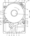
- FIG. 1 is a plan view of a magnetic disk device according to a first embodiment of the present invention with a top cover removed.
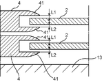
- FIG. FIG. 2 is an enlarged sectional view taken along line II-II in FIG. 1.
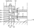
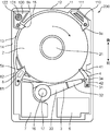
- FIG. 3 is an enlarged sectional view taken along line III-III in FIG. 1. It is a top view of the state which removed the top cover of the magnetic disc unit of 2nd Embodiment. It is a top view of the state which removed the top cover of the magnetic disc unit of 3rd Embodiment. It is a top view of the principal part of the magnetic disc apparatus of 4th Embodiment.
- a magnetic disk device 1 includes a casing 11, a magnetic recording medium 2 accommodated in the casing 11, a head actuator 3 provided with a magnetic head 31, and a magnetic head 31. Is provided at a predetermined position during non-operation, and a deflection limiting portion for limiting deflection occurring in the magnetic recording medium 2 is provided.
- the casing 11 includes a rectangular parallelepiped casing main body 12 having an upper surface opening, a casing main body 12 that closes the opening of the casing main body 12 from the upper side, and a top cover (not shown) having substantially the same shape.
- the casing body 12 includes a bottom wall 13 and a side wall 14, and a storage recess 15 is defined by the bottom wall 13 and the side wall 14.
- the storage recess 15 stores the magnetic recording medium 2, the head actuator 3, the deflection limiting portion, and the like.
- the magnetic recording medium 2 is two (see FIGS. 2 and 3) disk-shaped glass substrates (glass substrates) having the same configuration.
- the magnetic recording medium 2 has a thickness of 0.8 mm and a diameter of 64 mm.
- These magnetic recording media 2 are fixedly supported by the spindle motor 21 at the center as shown in FIG. 1 so as to have a predetermined distance in the axial direction (thickness direction). As the spindle motor 21 rotates, it is configured to rotate together.
- the head actuator 3 includes a plate-like suspension 32 provided with a plurality of (four in this embodiment) magnetic heads 31 at the tip, and a plate-like arm 33 that supports the suspension 32.
- suspensions 32 there are four suspensions 32 (only one uppermost side appears in FIG. 1).
- the magnetic heads 31 are attached to the front ends of the suspensions 32, respectively.
- the number of arms 33 is the same as the number of suspensions 32 (similar to suspension 32, only the uppermost one appears in FIG. 1).
- the distal end side of each arm 33 is connected to the proximal end side of each suspension 32 to support the suspension 32.
- each arm 33 is held by a shaft 16 provided in the casing body 12 so as to be sequentially rotatable with a space in the vertical direction.
- the suspensions 32 are also arranged with a space therebetween in the vertical direction, and the magnetic head 31 is arranged between the suspensions 32 and faces each other.
- reference numeral 6 in FIG. 1 denotes a substrate unit having a plurality of electronic components, and the substrate unit 6 and the magnetic head 31 are electrically connected.
- the arm 31 configured in this manner is configured to be rotated by a voice coil motor 7 provided in the casing 11.
- the voice coil motor 7 includes a support frame 17 that is rotatably supported by the shaft 16 so as to extend from the shaft 16 in a direction opposite to the arm 31, and a voice coil supported by the support frame 17. (Not shown), a yoke (not shown) disposed on both sides of the voice coil and fixed to the casing body 12 and a magnet (not shown) fixed to the yoke.
- each of the magnetic heads 31 moves while floating on the upper surface or the lower surface of the magnetic recording medium 2 with a certain distance. During the movement, each magnetic head 31 performs an operation of reading (reproducing) or writing (recording) on the magnetic recording medium 2.
- the ramp 4 is disposed on the outer peripheral side of the magnetic recording medium 2 and on the front end side of the head actuator 3, and is disposed vertically corresponding to the magnetic recording medium 2.
- the ramp 4 of the first embodiment includes a guide part 41 provided on the front end side, and a holding part 42 that extends from the guide part 41 to the outer peripheral side of the magnetic recording medium 2 and holds the head actuator 3. ing.
- the guide portion 41 is for sliding and guiding a tab 34 provided at the tip of the head actuator 3, and the distance from the top surface or the bottom surface of the magnetic recording medium 2 gradually increases from the tip to the holding portion 42 side. It is formed in a curved shape.
- the holding unit 42 holds the tab 34 of the head actuator 3 guided from the guide unit 41, so that the magnetic head 31 is separated from the outer periphery of the magnetic recording medium 2 to the outer peripheral side by a predetermined distance. 3 to hold.
- the base end side of the lamp 4 configured in this way is fixed to the casing body 12 by fixing means such as bolts. Further, in this fixed state, the tip of the guide portion 41 is separated from the upper surface and the lower surface of the magnetic recording medium 2 by a predetermined distance, and with respect to a part of the outer peripheral edge on the upper surface and the lower surface of the magnetic recording medium 2. It faces in a non-contact state along the axial direction (thickness direction).
- the distance between the ramp 4 and the upper surface of the magnetic recording medium 2 is the distance L1 between the upper surface of the magnetic recording medium 2 described later and the first deflection limiting members 5a, 5b, 5c (shown in FIG. 3). Is set to the same. The distance between the lamp 4 and the lower surface of the magnetic recording medium 2 is set to the same distance L2 as the distance L1.
- the magnetic recording medium 2 rotates by setting the distance between the ramp 4 and the upper surface of the magnetic recording medium 2 and the distance between the ramp 4 and the lower surface of the magnetic recording medium 2 to be the same.
- the magnetic recording medium 2 is configured to generate substantially the same air flow with respect to the upper surface (one surface) and the lower surface (other surface).
- the deflection limiting unit includes first deflection limiting members 5a, 5b, and 5c and a second deflection limiting member.
- the second deflection limiting member is composed of the lamp 4.
- the first deflection limiting members 5a, 5b, and 5c are formed of three synthetic resin products disposed on the left front side, the left rear side, and the right rear side in the housing recess 15 of the casing body 12, respectively. As shown in FIG. 3, each of the first deflection limiting members 5 a, 5 b, 5 c includes two insertion grooves 51 for inserting a part of the outer peripheral edge of each magnetic recording medium 2 on the tip side.
- the first deflection limiting members 5a, 5b, 5c configured as described above and the ramp 4 as the second deflection limiting member are arranged in the circumferential direction along the circumferential direction of the magnetic recording medium 2 as shown in FIG. It arrange
- the base end sides of the first deflection limiting members 5a, 5b, and 5c arranged as described above are fixed to the bottom wall 13 of the casing body 12 by fixing means such as bolts.
- fixing means such as bolts.
- the outer peripheral edge of each magnetic recording medium 2 is inserted into each insertion groove 51.
- the inner surfaces of the insertion grooves 51 of the first deflection limiting members 5a, 5b, and 5c face the outer peripheral edge of the magnetic recording medium 2 in a non-contact state along the axial direction with respect to both sides of the magnetic recording medium 2.
- the inner surfaces of the insertion grooves 51 of the first deflection limiting members 5a, 5b, and 5c face the outer peripheral edge of the magnetic recording medium 2 that has entered the insertion grooves 51 in a non-contact state.
- the distance L1 between the upper surface of the magnetic recording medium 2 and the inner upper wall 52 of the insertion groove 51, the lower surface of the magnetic recording medium 2, and the insertion groove is set to be the same, and when the magnetic recording medium 2 rotates, substantially the same air flow can be generated on the upper and lower surfaces of the magnetic recording medium 2.
- the distance L1 and the distance L2 are about 0.4 mm.
- the distance between the upper and lower surfaces of the magnetic recording medium 2 and the magnetic head 31 is several nanometers. However, the magnetic head 31 floats due to the air flow generated when the magnetic recording medium 2 rotates. Even if a deflection occurs in the magnetic recording medium 2 during the read / write operation according to, the magnetic head 31 is not contacted.
- the distance L3 between the outer peripheral edge of the magnetic recording medium 2 that has entered the insertion groove 51 and the inner wall 54 of the insertion groove 51 is about 1 mm.
- the first deflection limiting member 5a on the left front side is formed integrally with the filter holding member 8 provided on the magnetic disk device 100, and the first rear right side is also provided.
- One deflection limiting member 5 c is formed integrally with a desiccant holding member 110 provided in the magnetic disk device 100.
- a synthetic resin filter holding member 8 is provided in the vicinity of the magnetic recording medium 2 on the left front side of the housing recess 15 of the casing body 12 of the second embodiment, and the magnetic recording medium on the right rear side.
- a desiccant holding member 110 made of synthetic resin is provided in the vicinity of 2.
- the filter holding member 8 has an opening 82 on the lower surface, and includes a removal filter 81 for removing dust and gas inside.
- the first deflection limiting member 5 a on the left front side is formed integrally with the filter holding member 8 on the tip side of the filter holding member 8.
- the desiccant holding member 110 holds therein a desiccant 111 such as silica gel as a humidity control agent for controlling the humidity, and prevents rust and deterioration of parts of the magnetic disk device 100.
- a desiccant 111 such as silica gel as a humidity control agent for controlling the humidity, and prevents rust and deterioration of parts of the magnetic disk device 100.
- the first deflection limiting member 5 c on the right rear side is formed integrally with the desiccant holding member 110 on the tip side of the desiccant holding member 110.
- the rest of the second embodiment has the same configuration as that of the first embodiment.
- the first deflection limiting members 5a and 5c can be manufactured together when the filter holding member 8 and the desiccant holding member 110 are manufactured.
- the first deflection limiting members 5a and 5c can be assembled at the same time. Therefore, the first deflection limiting members 5a and 5c can be manufactured and assembled easily and at low cost.
- the first left deflection limiting member 5b is formed integrally with an air filter holding member 120 provided in the magnetic disk device 200.
- a synthetic resin air filter holding member 120 is provided in the vicinity of the magnetic recording medium 2 on the left rear side of the housing recess 15 of the casing body 12.
- the air filter holding member 120 includes a holding hole 122, and the air hole air filter 121 is held in the holding hole 122.
- the air filter holding member 120 covers the air vent (not shown) provided in the bottom wall 13 of the casing body 12 with the air filter 121 for the air vent while holding the air filter 121 for the air vent. And attached to the bottom wall 13 of the casing body 12.
- the first deflection limiting member 5b on the left rear side is formed integrally with the air filter holding member 120 on the tip side of the air filter holding member 120.
- the rest of the third embodiment has the same configuration as that of the second embodiment.
- the first deflection limiting members 5a and 5c are formed integrally with the filter holding member 8 and the desiccant holding member 110, respectively.
- the first deflection limiting member 5b can be manufactured together, and at the same time when the air filter holding member 120 is assembled to the magnetic disk device 200, the first deflection limiting member 5b can also be assembled. . Therefore, the first deflection limiting member 5b can be easily manufactured and assembled at a low cost.
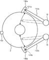
- the magnetic disk device 300 according to the fourth embodiment includes two head actuators 130a and 130b, two ramps 140a and 140b, and one first deflection limiting member 150.
- the head actuator includes a first head actuator 130a provided with a plurality of first magnetic heads 131a and a second head actuator 130b provided with a plurality of second magnetic heads 131b.
- the configuration is substantially the same as that of the first embodiment, and they are arranged separately from each other so as to be movable with respect to the magnetic recording medium 2.
- the magnetic disk device 300 of the fourth embodiment reads and writes data on the magnetic recording medium 2 at high speed. To be able to do it.
- the ramp includes a first ramp 140a that holds the first magnetic head 131a via a first head actuator 130a, and a second ramp 140b that holds the second magnetic head 131b via a second head actuator 130b. Each of them has substantially the same configuration as that of the first embodiment.
- the first lamp 140a and the second lamp 140b constitute a second deflection limiting member.
- the first deflection limiting member 150 is disposed at substantially the center in the circumferential direction of the magnetic recording medium 2 in the first ramp 140a and the second ramp 140b, whereby the first deflection limiting member 150, the first ramp 140a, and the second ramp.
- the ramps 140b are arranged along the circumferential direction of the magnetic recording medium 2 so that the adjacent ones in the circumferential direction are substantially equidistant.
- the second deflection limiting member can be configured by two of the first lamp 140a and the second lamp 140b, and one first deflection limiting member 150 can be configured by the first lamp 140a and the second lamp. If the magnetic recording medium 2 is disposed between the magnetic recording medium 2 and the magnetic recording medium 2, the magnetic recording medium 2 adjacent to each other in the circumferential direction can be disposed at almost equal intervals. Therefore, the deflection limiting portion can be made simple and can be manufactured at low cost.
- the first deflection limiting member and the second deflection limiting member are arranged at substantially equal intervals in the circumferential direction.
- the present invention is not limited to this configuration and can be changed as appropriate.
- the first deflection limiting member is disposed on both the upper and lower surfaces of the magnetic recording medium 2.
- the present invention is not limited to this, and either the upper surface or the lower surface of the magnetic recording medium 2 is used. You may provide corresponding to one surface.
- the ramps 4, 140a, 140b are arranged so as to face the part of the outer peripheral edge of the magnetic recording medium 2 along the axial direction to form the second deflection limiting member. Not only the form but also can be changed as appropriate.
- a lamp may be arranged on the outer side in the radial direction of the outer peripheral edge of the magnetic recording medium 2 with a distance from the outer peripheral edge, and the deflection limiting portion may be configured by only the first deflection limiting member.
- the deflection limiting portion may be configured by only the first deflection limiting member.
- the magnetic disk device 1 includes the glass magnetic recording medium 2 having a thickness of 1 mm or less.
- the magnetic recording medium 2 is not limited to this embodiment, and has a thickness, for example. May exceed 1 mm, or may be made of synthetic resin, and can be changed as appropriate.
- the number of magnetic recording media 2 is not limited to two, but may be one or three or more. And what is necessary is just to provide a 1st deflection limiting member and a 2nd deflection limiting member with respect to each of them.
- the present invention did not describe the magnetic recording method in detail.
- the load unloading method does not depend on the recording method such as the in-plane recording method, the perpendicular magnetic recording method, and the heat-assisted magnetic recording method. Any type of magnetic disk device can be widely applied.
- the present invention is particularly effective in a magnetic disk device built in a portable personal computer or a portable storage system.
- the substrate material of the magnetic recording medium has not been described in detail.
- the smoothness may be deteriorated by the chemical strengthening treatment, it is desirable to adjust the smoothness of the surface by performing precise polishing after the chemical strengthening treatment.
- the substrate of the magnetic recording medium is made of a material that is weak against impact force, for example, made of glass
- the external force that the magnetic recording medium receives from the outside can reduce the risk of flexing and breaking.
- the magnetic head is on the magnetic recording medium. Therefore, when the deflection is performed or when the deflection is restored, the magnetic head It is possible to prevent the recording surface of the magnetic recording medium from being damaged due to contact.
- the first deflection limiting member is formed with an insertion groove into which the part is inserted so as to face both sides of the magnetic recording medium along the axial direction.
- the outer peripheral edge of the magnetic recording medium can be received by the guide portions from both sides in the axial direction, and more reliably, the crack due to the deflection of the magnetic recording medium caused by the external force, Alternatively, contact with the magnetic head due to deflection when the magnetic disk device is in operation can be prevented.
- the first deflection limiting member is configured to generate a substantially equal air flow on both surfaces of the magnetic recording medium when the magnetic recording medium rotates.
- an insertion groove is provided in the first deflection limiting member, and the inner surface of the insertion groove is arranged at a substantially equal distance from each of both axial surfaces of the magnetic recording medium, and when the magnetic recording medium rotates, An approximately equal air flow is generated on both sides. Thereby, even when the magnetic recording medium is rotated at a high speed, the vibration can be suppressed by the air flow, and the deflection of the magnetic recording medium can be suppressed.
- a plurality of the first deflection limiting members are arranged along the circumferential direction of the magnetic recording medium.
- the air flow around the magnetic recording medium can be guided more reliably. Further, the deflection of the magnetic recording medium can be more effectively prevented.
- the ramp is disposed so as to face a part of the outer peripheral edge of the magnetic recording medium in a non-contact state along the axial direction
- the deflection limiting portion includes a second deflection limiting member
- the second deflection limiting member is constituted by the ramp
- the first deflection limiting member and the second deflection limiting member are arranged so that the circumferentially adjacent ones are substantially equidistant from each other.
- the magnetic recording medium is preferably disposed along the circumferential direction.
- the amount of deflection of the magnetic recording medium can be further reduced, and it is possible to more reliably prevent the magnetic recording medium from cracking due to deflection or contact with the magnetic head due to deflection.
- the lamp can be used as the second deflection limiting member of the deflection limiting portion, and the deflection limiting portion can be manufactured at a low cost.
- a filter holding member holding a removal filter for removing dust and gas is provided in the vicinity of the magnetic recording medium, and the first deflection limiting member is formed integrally with the filter holding member. Preferably it is.
- the first deflection limiting member can be manufactured at the same time when the removal filter is manufactured, and the first deflection limiting member can also be assembled at the same time when the removal filter is assembled to the magnetic disk device. Therefore, the first deflection limiting member can be manufactured and assembled easily and at low cost.
- an air filter holding member holding a vent air filter is provided in the vicinity of the magnetic recording medium, and the first deflection limiting member is formed integrally with the air filter holding member. It is preferable.
- the first deflection limiting member can be manufactured at the same time when the air filter holding member is manufactured, and the first deflection limiting member can also be mounted at the same time when the air filter is assembled to the magnetic disk device. Therefore, the first deflection limiting member can be manufactured and assembled easily and at low cost.
- a desiccant storage member storing a desiccant is provided in the vicinity of the magnetic recording medium, and the first deflection limiting member is formed integrally with the desiccant storage member.
- the first deflection limiting member can be manufactured at the same time when the desiccant holding member is manufactured, and the first deflection limiting member can be also mounted at the same time when the desiccant holding member is assembled to the magnetic disk device. it can. Therefore, the first deflection limiting member can be manufactured and assembled easily and at low cost.
- a first head actuator arranged to be movable with respect to the magnetic recording medium, and a second head actuator arranged to be movable with respect to the magnetic recording medium separately from the first head actuator;
- the magnetic head includes a first magnetic head attached to the first head actuator, and a second magnetic head attached to the second head actuator, and the ramp includes the first head actuator.
- a first ramp for holding the first magnetic head via the second ramp and a second ramp for holding the second magnetic head via the second head actuator, wherein the second deflection limiting member comprises: It is preferable that the lamp is composed of a first lamp and a second lamp.
- the first ramp in the magnetic disk device configured to allow the first magnetic head and the second magnetic head to perform a read / write operation on the magnetic recording medium at a double speed. Since the second lamp and the second lamp are used as the second deflection limiting member, the deflection limiting portion can be manufactured at a low cost.
- the magnetic recording medium substrate is preferably made of glass.
- a magnetic recording medium made of a glass substrate having a low impact strength against an impact force can be made difficult to break, and can be made suitable for an apparatus having a glass magnetic recording medium.
- the magnetic recording medium has a thickness of 1 mm or less.
Landscapes
- Recording Or Reproducing By Magnetic Means (AREA)
Abstract
磁気記録媒体2と、磁気ヘッド31を有するヘッドアクチュエータ3と、ランプ4と、3つの第1たわみ制限部材5a、5b、5cとを備えている。第1たわみ制限部材5a、5b、5cは、磁気記録媒体2の両面側における外周縁の一部に対し、軸方向に沿って非接触状態で臨むように、磁気記録媒体2の周方向に沿って配置され、外力によって磁気記録媒体2に生じるたわみを抑えることができるように構成されている。
Description
本発明は、磁気ディスク装置に関し、詳しくは、非動作時の磁気ヘッドをランプによって保持できるようにした磁気ディスク装置に関するものである。
従来から、非動作時の磁気ヘッドをランプによって保持できるようにしたロードアンロード方式の磁気ディスク装置は知られており、例えば特許文献1に開示されたものがある。
この特許文献1に開示された磁気ディスク装置は、回転可能に支持された円板状の磁気記録媒体と、この磁気記録媒体に対して移動して読み書きの動作を行なう磁気ヘッドと、非動作時の磁気ヘッドを磁気記録媒体から離間した位置に保持するためのランプとを備えている。
しかしながら、上記特許文献1に開示の磁気ディスク装置においては、例えば磁気ディスク装置が床面等に落下して磁気記録媒体の基板が外部から衝撃力を受けたような場合に、その衝撃力によって磁気記録媒体がたわむことがある。その結果、磁気記録媒体の基板がガラス製のものであるような場合には割れるおそれが高い。又、磁気記録媒体が割れずにたわみが大きい場合には、たわむ際に、或いは、たわみが元に戻る際に、磁気ヘッドと接触して磁気記録媒体の記録面を損傷するおそれがある、という問題点がある。
本発明は、磁気記録媒体に生じるたわみを抑え、磁気記録媒体が割れ、或いは、磁気ヘッドと接触するおそれの少ない磁気ディスク装置の提供を目的とする。
上記課題を解決するため、本発明は、回転可能に支持された円板状の磁気記録媒体と、前記磁気記録媒体に動作する磁気ヘッドと、前記磁気記録媒体の外周側に設けられ、非動作時の前記磁気ヘッドを、前記磁気記録媒体から離間した位置に保持するランプとを備えた磁気ディスク装置において、前記ランプと磁気記録媒体の周方向に距離を隔てた位置に設けられ、前記磁気記録媒体に生じるたわみを制限するたわみ制限部を備え、前記たわみ制限部は、前記磁気記録媒体の少なくとも一面側における外周縁の一部に対し、軸方向に沿って非接触状態で臨む、少なくとも1つの第1たわみ制限部材を備えていることを特徴とする磁気ディスク装置である。
本発明によれば、例えば磁気ディスク装置が床面等に落下し、磁気記録媒体が外力として衝撃力を受けて磁気記録媒体にたわみが生じると、その磁気記録媒体が第1たわみ制限部材に当接して、それ以上の磁気記録媒体のたわみが制限される。
本発明のさらに具体的な目的、構成、作用効果は、以下の図面を参照した詳細な説明から明らかになるであろう。
以下、本発明を実施するための形態について、図面を参照しながら詳細に説明する。各実施形態において、同等の部材には同一の符号を付し、重複する説明は省略する。
図1を参照して、第1実施形態の磁気ディスク装置1は、ケーシング11と、ケーシング11内に収納された磁気記録媒体2と、磁気ヘッド31が付設されたヘッドアクチュエータ3と、磁気ヘッド31を非動作時に所定位置で保持するためのランプ4と、磁気記録媒体2に生じるたわみを制限するたわみ制限部とを備えている。
ケーシング11は、上面開口の直方体状のケーシング本体12と、ケーシング本体12の開口を上方側から閉鎖するケーシング本体12と略同形状の図示しないトップカバーとから構成されている。
ケーシング本体12は、底壁13と、側壁14とを備え、これらの底壁13と側壁14とによって、収納凹部15が区画形成されている。この収納凹部15は、上記磁気記録媒体2、ヘッドアクチュエータ3、及びたわみ制限部等を収納する。
この実施形態では、磁気記録媒体2は、同一構成を採る2枚(図2、図3参照)の円板状のガラス製の基板(ガラス基板)である。磁気記録媒体2の厚さは、0.8mmで、直径が64mmである。
そして、これらの磁気記録媒体2は、軸方向(厚さ方向)に、互いに上下に所定の距離をもつようにして、図1に示すように、中央部がスピンドルモータ21に固定的に支持されており、スピンドルモータ21の回転に伴い、共に回転するように構成されている。
ヘッドアクチュエータ3は、先端に複数(この実施形態では4つ)の磁気ヘッド31が付設された板状のサスペンション32と、サスペンション32を支持した板状のアーム33とを備えている。
サスペンション32は、この実施形態では、4つである(図1では、最上側の1つだけが表れている)。そして、磁気ヘッド31は、夫々、サスペンション32夫々の先端側に付設されている。
アーム33は、サスペンション32と同数の4つである(サスペンション32と同様に、図1では、最上側の1つだけが表れている)。アーム33夫々の先端側は、サスペンション32夫々の基端側と連結されてサスペンション32を支持している。
一方、アーム33夫々の基端側は、互いに上下方向に間隔を持って、ケーシング本体12に設けられた軸16に順次回転自在に保持されている。又、このアーム33が保持された状態で、サスペンション32も互いに上下方向に間隔を持って配設されているとともに、磁気ヘッド31がサスペンション32間に配設されて互いに対向している。
尚、図1中の6は、複数の電子部品を有する基板ユニットを示しており、この基板ユニット6と磁気ヘッド31とが電気的に接続されている。
このように構成されたアーム31は、ケーシング11内に設けられたボイスコイルモータ7によって回動するように構成されている。詳しくは、ボイスコイルモータ7は、上記軸16からアーム31と反対方向に延ばされるようにしてその軸16に回動自在に支持された支持枠17と、その支持枠17に支持されたボイスコイル(図示せず)と、ボイスコイルの両側に配置され、ケーシング本体12に固定状に設けられたヨーク(図示せず)及びヨークに固定された磁石(図示せず)とを備えている。
そして、ボイスコイルモータ7に通電されることにより、アーム33が軸16回りに回動する。又、そのアーム33の回動に際して、磁気ヘッド31夫々が、磁気記録媒体2の上面または下面を、一定の距離を持って浮いた状態で移動する。そして、その移動に際して磁気ヘッド31夫々が磁気記録媒体2に対して読み(再生)または書き込み(記録)等する動作を行なう。
次に、ランプ4について説明する。ランプ4は、図1、図2に示すように、磁気記録媒体2の外周側であって、ヘッドアクチュエータ3の先端側に配置され、磁気記録媒体2に対応して上下に配設されている。また、この第1実施形態のランプ4は、先端側に設けられた案内部41と、案内部41から磁気記録媒体2の外周側に延ばされヘッドアクチュエータ3を保持する保持部42とを備えている。
案内部41は、ヘッドアクチュエータ3の先端に設けられたタブ34を摺動させて案内するためのもので、先端から保持部42側に漸次磁気記録媒体2の上面または下面からの距離が漸次大きくなる湾曲状に形成されている。
保持部42は、上記案内部41から案内されてきたヘッドアクチュエータ3のタブ34を保持することにより、磁気ヘッド31を、磁気記録媒体2の外周から所定距離だけ外周側に離間した位置にヘッドアクチュエータ3を介して保持する。
このように構成されたランプ4は、その基端側がケーシング本体12にボルト等の固定手段によって固定されている。又、この固定状態で、案内部41の先端は、磁気記録媒体2の上面、下面夫々から所定の距離を隔てているとともに、磁気記録媒体2の上面及び下面における外周縁の一部に対し、軸方向(厚さ方向)に沿って非接触状態で臨んでいる。
又、この実施形態では、ランプ4と磁気記録媒体2の上面との距離は、後述する磁気記録媒体2の上面と第1たわみ制限部材5a、5b、5cとの距離L1(図3に図示)と同じに設定されている。又、ランプ4と磁気記録媒体2の下面との距離は、上記距離L1と同じ距離L2に設定されている。
このようにして、ランプ4と磁気記録媒体2の上面との距離と、ランプ4と磁気記録媒体2の下面との距離とが同じになるように設定することにより、磁気記録媒体2が回転する際に、磁気記録媒体2の上面(一面)、下面(他面)に対して略等しい空気流を発生させ得るように構成されている。
次に、たわみ制限部について説明する。たわみ制限部は、第1たわみ制限部材5a、5b、5cと、第2たわみ制限部材とを備えている。第2たわみ制限部材は、上記ランプ4で構成されている。
第1たわみ制限部材5a、5b、5cは、ケーシング本体12の収納凹部15における左前方側、左後方側及び右後方側夫々に配設された3個の合成樹脂製品で構成されている。各第1たわみ制限部材5a、5b、5cは、図3に示すように、先端側に、磁気記録媒体2夫々の外周縁の一部を挿入する2つの挿入溝51を備えている。
このように構成された第1たわみ制限部材5a、5b、5cと第2たわみ制限部材としてのランプ4とは、図1に示すように磁気記録媒体2の周方向に沿って、周方向に互いに隣接するもの同士が略等間隔になるように配置されている。
そして、上記のように配設された第1たわみ制限部材5a、5b、5cは、夫々、その基端側がケーシング本体12の底壁13にボルト等の固定手段によって固定されている。この固定状態で、図3に示すように、挿入溝51夫々に、磁気記録媒体2夫々の外周縁が入り込んだ状態になっている。第1たわみ制限部材5a、5b、5cの挿入溝51の内面は、磁気記録媒体2の両面側に対し、磁気記録媒体2の外周縁を軸方向に沿って非接触状態で臨んでいる。同様に、第1たわみ制限部材5a、5b、5cの挿入溝51の内面は、当該挿入溝51に入り込んだ磁気記録媒体2の外周縁端と非接触状態で臨んでいる。
又、挿入溝51夫々に磁気記録媒体2の外周縁が入り込んだ状態で、磁気記録媒体2の上面と挿入溝51の内上壁52との距離L1と、磁気記録媒体2の下面と挿入溝51の内下壁53との距離L2が同じになるように設定され、磁気記録媒体2が回転する際に、磁気記録媒体2の上下両面に対して略等しい空気流を発生させ得るように構成されている。この実施形態では、上記距離L1及び距離L2は、0.4mm程度とされている。
なお、磁気記録媒体2の上下面と磁気ヘッド31との間隔は、数nmであるが、磁気記録媒体2が回転する際に発生する空気流により、磁気ヘッド31が浮上するため、磁気ヘッド31による読み書き動作中に磁気記録媒体2にたわみが発生したとしても、磁気ヘッド31に接触することはない。
また、挿入溝51に入り込んだ磁気記録媒体2の外周縁端と挿入溝51の内側壁54との距離L3が、1mm程度とされている。
次に、以上のように構成された第1実施形態の落下衝撃試験を行なったので、以下に説明する。試験は、第1たわみ制限部材5a、5b、5cを有する上記第1実施形態の磁気ディスク装置1を5個、準備し、それらを落下させて磁気ディスク装置1に1000G(=9800m/s2)の衝撃加速度をかけるようにして行い、磁気ディスク装置1の磁気記録媒体2が割れたか否かを、夫々について調べた。
又、比較試験として、第1たわみ制限部材を有しない比較品(第1たわみ制限部材を有していないこと以外は上記第1実施形態のものと同じ)を5個、製作し、上記と同条件で、5個夫々について行なった。
試験の結果は、本発明の第1実施形態のものは、5個全て、磁気記録媒体2の割れは生じなかった。これに対して、比較品は、5個の内、2個が割れを生じた。
次に、本発明の第2実施形態の磁気ディスク装置100について、図4に基づいて説明する。第2実施形態の磁気ディスク装置100は、左前方側の第1たわみ制限部材5aが、磁気ディスク装置100に設けられたフィルタ保持部材8と一体的に形成されているとともに、右後方側の第1たわみ制限部材5cが、磁気ディスク装置100に設けられた乾燥剤保持部材110と一体的に形成されている。
詳しくは、第2実施形態のケーシング本体12の収納凹部15の左前方側における磁気記録媒体2の近傍に、合成樹脂製のフィルタ保持部材8が設けられているとともに、右後方側における磁気記録媒体2の近傍に、合成樹脂製の乾燥剤保持部材110が設けられている。
フィルタ保持部材8は、下面に開口部82を有し、内部に、粉塵やガスを除去するための除去フィルタ81を備えている。
左前方側の第1たわみ制限部材5aは、そのフィルタ保持部材8の先端側に、フィルタ保持部材8と一体的に形成されている。
乾燥剤保持部材110は、内部に、湿度を制御する湿度制御剤としてのシリカゲル等の乾燥剤111を保持し、磁気ディスク装置100の部品の錆や劣化を防ぐようになっている。
そして、右後方側の第1たわみ制限部材5cは、その乾燥剤保持部材110の先端側に、乾燥剤保持部材110と一体的に形成されている。第2実施形態のその他は、先の第1実施形態のものと同構成を採っている。
このように構成された第2実施形態の磁気ディスク装置100においては、フィルタ保持部材8、乾燥剤保持部材110夫々を製作する際に第1たわみ制限部材5a、5cも一緒に製作できるとともに、フィルタ保持部材8、乾燥剤保持部材110夫々を磁気ディスク装置100に組み付ける際に同時に第1たわみ制限部材5a、5cも組み付けることができる。従って、第1たわみ制限部材5a、5cの製作及び組み付けを容易に且つ低コストに行うことができる。
次に、本発明の第3実施形態の磁気ディスク装置200について、図5に基づいて説明する。第3実施形態の磁気ディスク装置200は、左後方側の第1たわみ制限部材5bが、磁気ディスク装置200に設けられたエアフィルタ保持部材120と一体的に形成されている。
詳しくは、ケーシング本体12の収納凹部15の左後方側における磁気記録媒体2の近傍に、合成樹脂製のエアフィルタ保持部材120が設けられている。このエアフィルタ保持部材120は、保持孔122を備え、この保持孔122に、通気口用エアフィルタ121を保持している。
そして、エアフィルタ保持部材120は、通気口用エアフィルタ121を保持した状態で、ケーシング本体12の底壁13に設けられた通気口(図示せず)を通気口用エアフィルタ121で覆うようにして、ケーシング本体12の底壁13に取り付けられている。
左後方側の第1たわみ制限部材5bは、そのエアフィルタ保持部材120の先端側に、エアフィルタ保持部材120と一体的に形成されている。第3実施形態のその他は、先の第2実施形態のものと同構成を採っている。
このように構成された第3実施形態の磁気ディスク装置200においては、上述のフィルタ保持部材8や乾燥剤保持部材110夫々に第1たわみ制限部材5a、5cを一体的に形成する場合と同様に、エアフィルタ保持部材120を製作する際に第1たわみ制限部材5bも一緒に製作できるとともに、エアフィルタ保持部材120を磁気ディスク装置200に組み付ける際に同時に第1たわみ制限部材5bも組み付けることができる。従って、第1たわみ制限部材5bの製作及び組み付けを容易に且つ低コストに行うことができる。
次に、本発明の第4実施形態の磁気ディスク装置300について、図6に基づいて説明する。この第4実施形態の磁気ディスク装置300は、2つのヘッドアクチュエータ130a、130bと、2つのランプ140a、140bと、1つの第1たわみ制限部材150とを備えている。
より詳しくは、ヘッドアクチュエータは、複数の第1磁気ヘッド131aが付設された第1ヘッドアクチュエータ130aと、複数の第2磁気ヘッド131bが付設された第2ヘッドアクチュエータ130bとを備えており、夫々は、先の第1実施形態のものとほぼ同構成を採り、互いに別に磁気記録媒体2に対して移動可能に配設されている。これらの2つの別途に可動するヘッドアクチュエータ130a、130b夫々に付設された第1磁気ヘッド131a、第2磁気ヘッド131bによって、第4実施形態の磁気ディスク装置300は、磁気記録媒体2に対する読み書きを高速に行い得るようになっている。
ランプは、上記第1磁気ヘッド131aを、第1ヘッドアクチュエータ130aを介して保持する第1ランプ140aと、上記第2磁気ヘッド131bを、第2ヘッドアクチュエータ130bを介して保持する第2ランプ140bとを備えており、夫々は、先の第1実施形態のものとほぼ同構成を採る。
又、この第4実施形態では、これらの第1ランプ140aと第2ランプ140bとは、第2たわみ制限部材を構成する。
第1たわみ制限部材150は、第1ランプ140aと第2ランプ140bとにおける磁気記録媒体2の周方向のほぼ中央に配置され、これにより、第1たわみ制限部材150と第1ランプ140aと第2ランプ140bとは、磁気記録媒体2の周方向に沿って、周方向に隣接するもの同士がほぼ等間隔になるように配設されている。
このように構成することにより、第2たわみ制限部材を、第1ランプ140aと第2ランプ140bとの2つで構成でき、1つの第1たわみ制限部材150を、第1ランプ140aと第2ランプ140bとの間に配置すれば、磁気記録媒体2の周方向に隣接するもの同士がほぼ等間隔になるように配設できる。従って、たわみ制限部を簡単な構成にできるとともに、低コストで製作できる。
尚、上記実施形態では、第1たわみ制限部材と第2たわみ制限部材とを、周方向にほぼ等間隔に配設しているが、この形態のものに限らず、適宜変更できる。
又、上記実施形態では、第1たわみ制限部材を、磁気記録媒体2の上下の両面側に配設しているが、この形態のものに限らず、磁気記録媒体2の上面又は下面の何れか一方の面に対応して設けてもよい。
また、上記実施形態では、ランプ4、140a、140bを、磁気記録媒体2の外周縁の一部に対し、軸方向に沿って臨むように配置して、第2たわみ制限部材としたが、この形態のものに限らず、適宜変更できる。
例えばランプを、磁気記録媒体2の外周縁の径方向外側に、外周縁と距離を隔てて配置し、たわみ制限部を、第1たわみ制限部材のみで構成してもよい。又、その場合において、第1たわみ制限部材を、複数個で構成し、複数個の第1たわみ制限部材を磁気記録媒体2の周方向にほぼ等間隔になるように配設するのが好ましい。
又、上記実施形態では、厚さが1mm以下のガラス製の磁気記録媒体2を有する磁気ディスク装置1で構成しているが、磁気記録媒体2は、この形態のものに限らず、例えば厚さが1mmを超えるもの、又は、合成樹脂製のものでもよく、適宜変更できる。
また、磁気記録媒体2の枚数についても、2枚のものに限らず、1枚あるいは3枚以上のものでもよい。そして、それらの夫々に対して第1たわみ制限部材及び第2たわみ制限部材を設ければよい。
また、本発明は、上述の実施形態では、磁気記録の方式について詳しく述べなかったが、面内記録方式、垂直磁気記録方式、熱アシスト磁気記録方式などの、記録方式によらず、ロードアンロード方式の磁気ディスク装置であれば幅広く適用できるものである。また、本発明は、可搬型のパーソナルコンピュータや可搬型の記憶システムに内蔵された磁気ディスク装置において特に有効である。
また,上述の実施形態では、磁気記録媒体の基板材料について詳しく述べなかったが,基板自身の機械的強度の観点から、化学強化されたアルミノシリケートガラスを用いるのがよい。ただし,化学強化処理によって平滑性が悪化することがあるため、化学強化処理後には精密研磨をおこなうことで表面の平滑性を整えることが望ましい。
以上説明したように、本発明によれば、磁気記録媒体の基板が衝撃力に対して弱い材料からなるもの、例えばガラス製のもので構成されている場合でも、磁気記録媒体が外部から受ける外力によってたわんで割れるようなおそれの少ないものにできる。
又、例えば割れずにたわみが大きい場合に、磁気ディスク装置が動作中であれば、磁気ヘッドが磁気記録媒体上にあるため、そのたわむ際に、或いは、たわみが元に戻る際に磁気ヘッドと接触して磁気記録媒体の記録面が損傷するようなことを防止できる。
また本発明において、前記第1たわみ制限部材は、前記軸方向に沿って前記磁気記録媒体の両面側に臨むように、前記一部を挿入する挿入溝を形成していることが好ましい。
そのような態様によれば、磁気記録媒体がたわむ際に磁気記録媒体の外周縁を軸方向の両側から案内部で受けることができ、より確実に、外力によって生じる磁気記録媒体のたわみによる割れ、或いは、磁気ディスク装置が動作中であるときの、たわみによる磁気ヘッドとの接触を防止できる。
また本発明において、前記第1たわみ制限部材は、前記磁気記録媒体が回転する際に、前記磁気記録媒体の両面に対して略等しい空気流を発生させ得るように構成されていることが好ましい。
例えば第1たわみ制限部材に挿入溝を設け、この挿入溝の内面を、磁気記録媒体の軸方向の両面夫々から略等しい距離をもって配置して、磁気記録媒体が回転する際に、磁気記録媒体の両面に対して略等しい空気流を発生させるようにする。これにより、磁気記録媒体を高速回転した場合でも空気流によってその振動を抑え、磁気記録媒体のたわみを抑えることができる。
また本発明において、前記第1たわみ制限部材は、前記磁気記録媒体の周方向に沿って複数配設されていることが好ましい。
そのような態様によれば、磁気記録媒体回りの空気流をより確実に案内することができる。また、磁気記録媒体のたわみも、より効果的に防止することができる。
また本発明において、前記ランプは、前記磁気記録媒体の外周縁の一部に対し、軸方向に沿って非接触状態で臨むように配置され、前記たわみ制限部は、第2たわみ制限部材を、更に備え、前記第2たわみ制限部材は、前記ランプで構成され、前記第1たわみ制限部材と第2たわみ制限部材とは、互いに周方向に隣接するもの同士が略等間隔になるように、前記磁気記録媒体の周方向に沿って配設されていることが好ましい。
そのような態様によれば、磁気記録媒体のたわみ量を、より一層、少なくでき、より確実に、磁気記録媒体のたわみによる割れ、或いは、たわみによる磁気ヘッドとの接触を防止できる。
又、その際、ランプを、たわみ制限部の第2たわみ制限部材として利用でき、たわみ制限部を、低コストで製作できる。
また本発明において、前記磁気記録媒体の近傍に、粉塵やガスを除去する除去フィルタを保持したフィルタ保持部材が設けられ、前記第1たわみ制限部材は、前記フィルタ保持部材と一体的に形成されていることが好ましい。
そのような態様によれば、除去フィルタを製作する際に同時に第1たわみ制限部材も製作できるとともに、除去フィルタを磁気ディスク装置に組み付ける際に同時に第1たわみ制限部材も組み付けることができる。従って、第1たわみ制限部材の製作及び組み付けを容易且つ低コストに行うことができる。
また本発明において、前記磁気記録媒体の近傍に、通気口用エアフィルタを保持したエアフィルタ保持部材が設けられ、前記第1たわみ制限部材は、前記エアフィルタ保持部材と一体的に形成されていることが好ましい。
そのような態様によれば、エアフィルタ保持部材を製作する際に同時に第1たわみ制限部材も製作できるとともに、エアフィルタを磁気ディスク装置に組み付ける際に同時に第1たわみ制限部材も組み付けることができる。従って、第1たわみ制限部材の製作及び組み付けを容易且つ低コストに行うことができる。
また本発明において、前記磁気記録媒体の近傍に、乾燥剤を収納した乾燥剤収納部材が設けられ、前記第1たわみ制限部材は、前記乾燥剤収納部材と一体的に形成されていることが好ましい。
そのような態様によれば、乾燥剤保持部材を製作する際に同時に第1たわみ制限部材も製作できるとともに、乾燥剤保持部材を磁気ディスク装置に組み付ける際に同時に第1たわみ制限部材も組み付けることができる。従って、第1たわみ制限部材の製作及び組み付けを容易且つ低コストに行うことができる。
また本発明において、前記磁気記録媒体に対して移動可能に配置された第1ヘッドアクチュエータと、その第1ヘッドアクチュエータとは別に前記磁気記録媒体に対して移動可能に配置された第2ヘッドアクチュエータとが設けられ、前記磁気ヘッドは、前記第1ヘッドアクチュエータに付設された第1磁気ヘッドと、前記第2ヘッドアクチュエータに付設された第2磁気ヘッドとを備え、前記ランプは、前記第1ヘッドアクチュエータを介して第1磁気ヘッドを保持するための第1ランプと、前記第2ヘッドアクチュエータを介して第2磁気ヘッドを保持するための第2ランプとを備え、前記第2たわみ制限部材は、前記第1ランプと第2ランプとで構成されていることが好ましい。
そのような態様によれば、第1磁気ヘッドと第2磁気ヘッドとによって、磁気記録媒体に対して2倍の速度で読み書きの動作を行うことができるように構成した磁気ディスク装置における第1ランプと第2ランプとを、第2たわみ制限部材として利用するため、たわみ制限部を、低コストで製作できる。
また本発明において、前記磁気記録媒体の基板は、ガラス製のものであることが好ましい。
そのような態様によれば、衝撃力に対する衝撃強度が弱いガラス基板からなる磁気記録媒体でも割れ難いものにでき、ガラス製の磁気記録媒体を有する装置に適したものにできる。
また本発明において、前記磁気記録媒体は、その厚さが1mm以下のもので構成されていることが好ましい。
そのような態様によれば、外力を受けた場合にたわみ易く、しかもたわみ量が大きい磁気記録媒体でもたわみを抑えることができ、厚さが1mm以下の薄型の磁気記録媒体を有する装置に適したものにできる。
本発明は、上述した実施の形態に限定されるものではなく、本発明の要旨を逸脱しない範囲内において種々変更を加え得ることはいうまでもない。
Claims (11)
- 回転可能に支持された円板状の磁気記録媒体と、前記磁気記録媒体に動作する磁気ヘッドと、前記磁気記録媒体の外周側に設けられ、非動作時の前記磁気ヘッドを、前記磁気記録媒体から離間した位置に保持するランプとを備えた磁気ディスク装置において、
前記ランプと前記磁気記録媒体の周方向に距離を隔てた位置に設けられ、前記磁気記録媒体に生じるたわみを制限するたわみ制限部を備え、
前記たわみ制限部は、前記磁気記録媒体の少なくとも一面側における外周縁の一部に対し、軸方向に沿って非接触状態で臨む、少なくとも1つの第1たわみ制限部材を備えていることを特徴とする磁気ディスク装置。 - 前記第1たわみ制限部材は、前記軸方向に沿って前記磁気記録媒体の両面側に臨むように、前記一部を挿入する挿入溝を形成していることを特徴とする請求項1記載の磁気ディスク装置。
- 前記第1たわみ制限部材は、前記磁気記録媒体が回転する際に、前記磁気記録媒体の両面に対して略等しい空気流を発生させ得るように構成されていることを特徴とする請求項1又は2記載の磁気ディスク装置。
- 前記第1たわみ制限部材は、前記磁気記録媒体の周方向に沿って複数配設されていることを特徴とする請求項1から3の何れか1項に記載の磁気ディスク装置。
- 前記ランプは、前記磁気記録媒体の外周縁の一部に対し、軸方向に沿って非接触状態で臨むように配置され、
前記たわみ制限部は、第2たわみ制限部材を、更に備え、
前記第2たわみ制限部材は、前記ランプで構成され、
前記第1たわみ制限部材と第2たわみ制限部材とは、互いに周方向に隣接するもの同士が略等間隔になるように、前記磁気記録媒体の周方向に沿って配設されていることを特徴とする請求項1~4の何れか一項に記載の磁気ディスク装置。 - 前記磁気記録媒体の近傍に、粉塵やガスを除去する除去フィルタを保持したフィルタ保持部材が設けられ、
前記第1たわみ制限部材は、前記フィルタ保持部材と一体的に形成されていることを特徴とする請求項1~5の何れか一項に記載の磁気ディスク装置。 - 前記磁気記録媒体の近傍に、通気口用エアフィルタを保持したエアフィルタ保持部材が設けられ、
前記第1たわみ制限部材は、前記エアフィルタ保持部材と一体的に形成されていることを特徴とする請求項1~6の何れか一項に記載の磁気ディスク装置。 - 前記磁気記録媒体の近傍に、乾燥剤を収納した乾燥剤収納部材が設けられ、
前記第1たわみ制限部材は、前記乾燥剤収納部材と一体的に形成されていることを特徴とする請求項1~7の何れか一項に記載の磁気ディスク装置。 - 前記磁気記録媒体に対して移動可能に配置された第1ヘッドアクチュエータと、その第1ヘッドアクチュエータとは別に前記磁気記録媒体に対して移動可能に配置された第2ヘッドアクチュエータとをさらに備え、
前記磁気ヘッドは、前記第1ヘッドアクチュエータに付設された第1磁気ヘッドと、前記第2ヘッドアクチュエータに付設された第2磁気ヘッドとを備え、
前記ランプは、前記第1ヘッドアクチュエータを介して第1磁気ヘッドを保持するための第1ランプと、前記第2ヘッドアクチュエータを介して第2磁気ヘッドを保持するための第2ランプとを備え、
前記第2たわみ制限部材は、前記第1ランプと第2ランプとで構成されていることを特徴とする請求項5~8の何れか一項に記載の磁気ディスク装置。 - 前記磁気記録媒体の基板は、ガラス製のものであることを特徴とする請求項1~9の何れか一項に記載の磁気ディスク装置。
- 前記磁気記録媒体は、その厚さが1mm以下のもので構成されていることを特徴とする請求項1~10の何れか一項に記載の磁気ディスク装置。
Priority Applications (1)
| Application Number | Priority Date | Filing Date | Title |
|---|---|---|---|
| JP2012508047A JPWO2011121904A1 (ja) | 2010-03-31 | 2011-03-10 | 磁気ディスク装置 |
Applications Claiming Priority (2)
| Application Number | Priority Date | Filing Date | Title |
|---|---|---|---|
| JP2010-080030 | 2010-03-31 | ||
| JP2010080030 | 2010-03-31 |
Publications (1)
| Publication Number | Publication Date |
|---|---|
| WO2011121904A1 true WO2011121904A1 (ja) | 2011-10-06 |
Family
ID=44711674
Family Applications (1)
| Application Number | Title | Priority Date | Filing Date |
|---|---|---|---|
| PCT/JP2011/001412 Ceased WO2011121904A1 (ja) | 2010-03-31 | 2011-03-10 | 磁気ディスク装置 |
Country Status (2)
| Country | Link |
|---|---|
| JP (1) | JPWO2011121904A1 (ja) |
| WO (1) | WO2011121904A1 (ja) |
Cited By (3)
| Publication number | Priority date | Publication date | Assignee | Title |
|---|---|---|---|---|
| JP2021009749A (ja) * | 2019-06-29 | 2021-01-28 | ウェスタン デジタル テクノロジーズ インコーポレーテッド | 二重対称アクチュエータハードディスクドライブ |
| JP2021108234A (ja) * | 2019-12-27 | 2021-07-29 | 昭和電工株式会社 | 記録再生装置 |
| US12106775B2 (en) | 2022-09-06 | 2024-10-01 | Resonac Corporation | Recording and reproducing device with medium regulating portion |
Citations (6)
| Publication number | Priority date | Publication date | Assignee | Title |
|---|---|---|---|---|
| JPH0438691A (ja) * | 1990-06-01 | 1992-02-07 | Hitachi Ltd | 磁気ディスク装置 |
| JP2001101814A (ja) * | 1999-10-01 | 2001-04-13 | Toshiba Corp | ディスク記憶装置及びこれに用いられるディスク変形規制部材 |
| JP2004326949A (ja) * | 2003-04-25 | 2004-11-18 | Toshiba Corp | ディスク装置 |
| JP2005339744A (ja) * | 2004-05-31 | 2005-12-08 | Toshiba Corp | 呼吸フィルタを有するディスク装置 |
| JP2006172680A (ja) * | 2004-12-15 | 2006-06-29 | Masashi Asaama | レイドストライピングハードディスク |
| JP2009158000A (ja) * | 2007-12-26 | 2009-07-16 | Samsung Electronics Co Ltd | ディスク装置およびフィルタ |
-
2011
- 2011-03-10 JP JP2012508047A patent/JPWO2011121904A1/ja active Pending
- 2011-03-10 WO PCT/JP2011/001412 patent/WO2011121904A1/ja not_active Ceased
Patent Citations (6)
| Publication number | Priority date | Publication date | Assignee | Title |
|---|---|---|---|---|
| JPH0438691A (ja) * | 1990-06-01 | 1992-02-07 | Hitachi Ltd | 磁気ディスク装置 |
| JP2001101814A (ja) * | 1999-10-01 | 2001-04-13 | Toshiba Corp | ディスク記憶装置及びこれに用いられるディスク変形規制部材 |
| JP2004326949A (ja) * | 2003-04-25 | 2004-11-18 | Toshiba Corp | ディスク装置 |
| JP2005339744A (ja) * | 2004-05-31 | 2005-12-08 | Toshiba Corp | 呼吸フィルタを有するディスク装置 |
| JP2006172680A (ja) * | 2004-12-15 | 2006-06-29 | Masashi Asaama | レイドストライピングハードディスク |
| JP2009158000A (ja) * | 2007-12-26 | 2009-07-16 | Samsung Electronics Co Ltd | ディスク装置およびフィルタ |
Cited By (5)
| Publication number | Priority date | Publication date | Assignee | Title |
|---|---|---|---|---|
| JP2021009749A (ja) * | 2019-06-29 | 2021-01-28 | ウェスタン デジタル テクノロジーズ インコーポレーテッド | 二重対称アクチュエータハードディスクドライブ |
| JP7024002B2 (ja) | 2019-06-29 | 2022-02-22 | ウェスタン デジタル テクノロジーズ インコーポレーテッド | 二重対称アクチュエータハードディスクドライブ |
| JP2021108234A (ja) * | 2019-12-27 | 2021-07-29 | 昭和電工株式会社 | 記録再生装置 |
| JP7400463B2 (ja) | 2019-12-27 | 2023-12-19 | 株式会社レゾナック | 記録再生装置 |
| US12106775B2 (en) | 2022-09-06 | 2024-10-01 | Resonac Corporation | Recording and reproducing device with medium regulating portion |
Also Published As
| Publication number | Publication date |
|---|---|
| JPWO2011121904A1 (ja) | 2013-07-04 |
Similar Documents
| Publication | Publication Date | Title |
|---|---|---|
| US7672083B1 (en) | Disk drive with translatable ramp | |
| US8493690B1 (en) | Load-unload ramp structure with cantilevered fin portion configured to reduce drop shock in a hard-disk drive | |
| US20090279199A1 (en) | Method and apparatus for reducing slider contact probability in a load-unload (LUL) hard disk drive | |
| US7327530B2 (en) | Hard disk drive having disk damper and disk protector | |
| CN115881173B (zh) | 盘装置 | |
| US8339732B2 (en) | Baseplate with recessed region in a hard-disk drive (HDD) | |
| CN101159153A (zh) | 盘装置 | |
| JP4290674B2 (ja) | ロード/アンロード機構及び磁気ディスク装置 | |
| WO2011121904A1 (ja) | 磁気ディスク装置 | |
| CN115841826B (zh) | 盘装置 | |
| US8351159B2 (en) | Suspension for protecting a component from mechanical shock | |
| US7832083B2 (en) | Shipping comb usable with a head stack | |
| US7773345B2 (en) | Carriage for disk device | |
| CN101059960A (zh) | 用于擦除垂直记录介质的块擦除器 | |
| CN114078486B (zh) | 盘装置 | |
| JP7400404B2 (ja) | 記録再生装置 | |
| CN113053420A (zh) | 记录再现装置 | |
| JP4908615B2 (ja) | ヘッドサスペンションアッセンブリおよびこれを備えたディスク装置 | |
| JP7819068B2 (ja) | 磁気ディスク装置 | |
| CN115116491B (zh) | 盘装置 | |
| JP2001057032A (ja) | ディスク装置用ヘッドサスペンションおよびディスク装置用ヘッドアクチュエータ | |
| JP4234634B2 (ja) | 磁気ディスク装置 | |
| US12283292B2 (en) | Hard disk drive idle sweep for thermal asperity avoidance | |
| JP2025160708A (ja) | ランプおよび磁気ディスク装置 | |
| JP2005339744A (ja) | 呼吸フィルタを有するディスク装置 |
Legal Events
| Date | Code | Title | Description |
|---|---|---|---|
| 121 | Ep: the epo has been informed by wipo that ep was designated in this application |
Ref document number: 11762157 Country of ref document: EP Kind code of ref document: A1 |
|
| WWE | Wipo information: entry into national phase |
Ref document number: 2012508047 Country of ref document: JP |
|
| NENP | Non-entry into the national phase |
Ref country code: DE |
|
| 122 | Ep: pct application non-entry in european phase |
Ref document number: 11762157 Country of ref document: EP Kind code of ref document: A1 |