WO2011114951A1 - 通信システム、スイッチングハブ、およびルータ - Google Patents
通信システム、スイッチングハブ、およびルータ Download PDFInfo
- Publication number
- WO2011114951A1 WO2011114951A1 PCT/JP2011/055425 JP2011055425W WO2011114951A1 WO 2011114951 A1 WO2011114951 A1 WO 2011114951A1 JP 2011055425 W JP2011055425 W JP 2011055425W WO 2011114951 A1 WO2011114951 A1 WO 2011114951A1
- Authority
- WO
- WIPO (PCT)
- Prior art keywords
- port
- packet
- router
- frame
- switching hub
- Prior art date
- Legal status (The legal status is an assumption and is not a legal conclusion. Google has not performed a legal analysis and makes no representation as to the accuracy of the status listed.)
- Ceased
Links
Images




Classifications
-
- H—ELECTRICITY
- H04—ELECTRIC COMMUNICATION TECHNIQUE
- H04L—TRANSMISSION OF DIGITAL INFORMATION, e.g. TELEGRAPHIC COMMUNICATION
- H04L45/00—Routing or path finding of packets in data switching networks
- H04L45/16—Multipoint routing
Definitions
- the present invention relates to data relay technology, and more particularly to multicast data relay technology.
- a relay device used to construct a communication system is a router or a switching hub.
- a router is a relay device that connects from the first layer (physical layer) to the third layer (network layer) of the OSI reference model. Data is exchanged with other routers via an IP (Internet Protocol) network such as the Internet. It plays the role of sending and receiving.
- the switching hub is a relay device for connecting from the first layer to the second layer (data link layer), and a communication terminal (for example, a personal computer) located at the end of data communication is used as a communication network. Take the role of containing.
- the connection of the nth layer means performing data transfer control according to the communication protocol of the nth layer.
- the header portion of a frame that is a data block of the second layer has a MAC (Media Access Control) address that is a hardware address of a transmission device and a transmission destination communication device (relay device or communication terminal) of the frame. It is written as a transmission source address and a transmission destination address of the frame, and a packet which is a data block of the third layer is written in the payload portion.
- MAC Media Access Control
- IP address which is a communication address for identifying the transmission source and transmission destination in the third layer, is written as the transmission source address and transmission destination address of the packet.
- transfer control of the data block is performed based on the destination address written in the header part of the received data block. The data block transfer control performed by the router and the switching hub will be described below with reference to FIG.
- FIG. 8 is a diagram illustrating an example of a communication system including a router and a switching hub.
- a switching hub 30 is connected to the router 20, and communication terminals (receiving devices 40-1 to 40-4) that receive data transmitted from the transmitting device 10 are connected to the switching hub 30.
- the router 20 in FIG. 8 When the router 20 in FIG. 8 receives a frame containing a packet transmitted from the transmission device 10 to the reception device 40-1 (a frame in which the packet is written in the payload portion), the router 20 displays the header portion of the packet. If the destination IP address is an IP address assigned to a communication terminal under its control, the frame is transferred to the switching hub 30. On the other hand, when the packet included in the received frame is not transmitted to the subordinate communication terminal, the router 20 transfers the frame to another router according to the stored contents of the routing table. To do.
- the switching hub 30 in FIG. 8 has a plurality of ports connected to other communication devices (routers, other switching hubs, communication terminals), and each of the ports is associated with each of the plurality of ports. It stores the MAC address of the communication device to be connected.
- the switching hub 30 receives a frame via any of the ports, the switching hub 30 refers to the transmission destination MAC address written in the header part of the frame, and sends the frame to the port corresponding to the transmission destination MAC address. Is output.
- a port connected to the router or a port connected to the router via another switching hub
- These ports are called “downstream ports”.
- the switching hub performs frame transfer control based on the MAC address associated with each port and the transmission destination MAC address of the received frame. For this reason, when a frame containing an IP multicast packet is received from the upstream side, a wasteful data stream is generated on the downstream side of the switching hub.
- IP multicast is a mode in which a packet is not sent to a specific communication terminal, but is sent to a group of communication terminals (multicast group) that has declared reception of the packet.
- the packet destination address is the IP address assigned to the multicast group.
- a multicast MAC address generated from an IP address of a multicast group is used instead of a MAC address of a specific communication terminal.
- the switching hub Since the multicast MAC address is generated from the IP address of the multicast group, it does not match any of the MAC addresses associated with each port of the switching hub. As described above, when a frame having a destination MAC address that does not match any of the MAC addresses associated with each port is received, the switching hub sends the frame to all downstream ports (flooding). ) Is executed. For example, in the communication system shown in FIG. 8, even when the transmission device 10 transmits a packet to a certain multicast group and only the reception device 40-1 participates in the multicast group, the switching hub 30 Since the flooding is performed, the frame containing the packet addressed to the multicast group is also transferred to the receiving apparatuses 40-2 to 40-4.
- IGMP Internet Group Management Protocol
- IGMP Internet Group Management Protocol
- the router stores information indicating that there is a communication terminal participating in the multicast group under its own device (hereinafter, participation management process).
- participation management process a packet that is sent to the multicast group from the upstream side is called “join / leave management process” together with the process of deleting the information in response to the notice of leaving from the multicast group.
- Snooping means “peek”
- a switching hub equipped with an IGMP snooping function refers to the payload part of the packet contained in the frame received by the downstream port, and the packet is sent to the multicast group.
- an identifier indicating the multicast group for example, multicast MAC address: hereinafter referred to as multicast group identifier
- the frame is sent only to the downstream port associated with the multicast group identifier, and the other downstream side The frame is not sent to the port. This avoids the generation of useless data streams.
- Patent Document 1 is cited as a prior art document related to a switching hub having an IGMP snooping function.
- the present invention includes a plurality of downstream ports to which downstream communication devices are connected and upstream ports connected to upstream communication devices, which are received via each port.
- a communication system including one or more switching hubs that perform frame transfer control based on a transmission destination address of the frame, and a router located upstream of the one or more switching hubs, the one or more switching hubs For each of the plurality of downstream ports, whether each of the hubs has a packet included in a frame received by the downstream port transmitted according to a predetermined communication protocol for realizing multicast communication.
- the first processing for notifying the router of the port identifier indicating the downstream port and the second processing for opening / closing the downstream port in accordance with an instruction from the router are executed.
- the packet relayed to the router by the switching hub that is the notification source indicates that the router has joined the multicast group. If it is determined whether it is for notification according to the protocol with reference to the payload part of the packet, and if it is determined for notification of participation in the multicast group, the port identifier Only the downstream port indicated by the port identifier is Communication system configured to instruct to open to the loop to provide.
- the process of determining whether or not the IGMP Join is performed with reference to the payload portion of the packet is performed.
- the switching hub included in the communication system Refers to the header of the packet.
- the processing that refers to the header portion of the packet has a lower processing load than the processing that refers to the payload portion of the packet. For this reason, the switching hub included in the communication system is sufficient to have a lower processing capability than the conventional switching hub having the IGMP function, and the power consumption can be suppressed.
- a process for determining whether the packet is IGMP Join with reference to the payload portion of the packet is performed by the router, and the router instructs the switching hub to open and close the downstream port according to the determination result.
- the switching hub since the downstream port is opened and closed in accordance with an instruction from the router, no useless data stream is generated on the downstream side of the switching hub.
- the present invention is for transmitting and receiving a frame to and from a router via one or more other switching hubs or to and from a router without going through another switching hub. And a plurality of downstream ports for transmitting / receiving frames to / from a downstream communication device, and the transfer control of frames received via each port is based on the destination address of the frame
- a packet included in a frame received via the downstream port is in accordance with a predetermined communication protocol for realizing multicast communication. Whether the packet is transmitted or not is determined by referring to the header part of the packet, and the predetermined communication protocol is determined.
- a notification means for notifying the router of a port identifier indicating the downstream port, and a port opening / closing for opening / closing the downstream port according to an instruction from the router
- a switching hub having control means is provided.
- the present invention transfers a packet received via one or more switching hubs to another router, while transferring a packet received from the other router to the one or more switching hubs.
- a router configured to forward to a destination via a hub, a packet transmitted according to a predetermined communication protocol for realizing multicast communication is received from any of the one or more switching hubs.
- a packet transmitted according to a predetermined communication protocol for realizing multicast communication is received from any of the one or more switching hubs.
- notify the router of participation in the multicast group according to the predetermined communication protocol when receiving a notification indicating a port identifier indicating the port that has received the packet.
- the payload part of the packet A determination unit that determines whether the port identifier is to be notified, and the determination unit determines that it is for notifying participation in the multicast group.
- a router having port opening / closing instruction means for instructing to open only the port indicated by the identifier to the multicast group.
- a program that causes a computer to function as the determination unit and the port opening / closing instruction unit.
- FIG. 1 is a diagram illustrating a configuration example of a communication system 1A according to the first embodiment of the present invention.
- the same components as those in FIG. 8 are denoted by the same reference numerals.
- this communication system 1A is different from FIG. 8 in that a router 60 is provided instead of the router 20, and a switching hub 50 is provided instead of the switching hub 30.
- a router 60 is provided instead of the router 20
- a switching hub 50 is provided instead of the switching hub 30.
- the router 60 By causing the switching hub 50 to perform processing that clearly shows the features of this embodiment and to cooperate with each other, the downstream side of the switching hub 50 (that is, between the switching hub 50 and another receiving device 40-k). This prevents unnecessary data streams from being generated.
- the switching hub 50 and the router 60 that clearly show the features of the present embodiment will be mainly described.
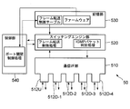
- FIG. 2 is a block diagram showing the configuration of the switching hub 50.
- the switching hub 50 includes a communication interface (hereinafter, “I / F”) unit 510, a switching engine unit 520, a storage unit 530, and a control unit 540.
- the control unit 540 is a CPU (Central Processing Unit), for example, and centrally controls the operation of each unit according to firmware stored in the storage unit 530. Processing executed by the control unit 540 according to this firmware will be described in detail later.
- I / F communication interface
- the control unit 540 is a CPU (Central Processing Unit), for example, and centrally controls the operation of each unit according to firmware stored in the storage unit 530. Processing executed by the control unit 540 according to this firmware will be described in detail later.
- CPU Central Processing Unit
- the communication I / F unit 510 is an interface that exchanges frames with other communication devices, and each of the plurality of ports to which the other communication devices are connected (ports 512U and 512D-1 to 512D in FIG. 2). -4 five ports).
- frames are exchanged with the connection destination communication device via each of the plurality of ports.
- 2 is an upstream port connected to the router 60
- the switching engine unit 520 is, for example, an ASIC (Application Specific Integrated Circuit).
- the switching engine unit 520 refers to the content stored in the frame transfer control table stored in the storage unit 530, and based on the transmission destination MAC address of the frame received via each port of the communication I / F unit 510.
- the above-described frame transfer control is performed.
- the switching engine unit 520 of the present embodiment executes the IGMP packet determination process shown in FIG. 3 prior to the transfer control of the frame.
- this IGMP packet determination processing is performed when the frame received via the downstream port includes an IGMP packet (whether or not it is IGMP Join).
- a dedicated frame (hereinafter referred to as a port identifier notification frame) is used for notifying the router 60 of the port identifier.
- type information indicating that the frame is a port identifier notification frame in addition to the MAC addresses of the transmission source (that is, the switching hub 50) and the transmission destination (router 60) of the frame. Is written.
- the port identifier of the downstream port that received the frame containing the IGMP packet is written in the payload portion of the port identifier notification frame.
- the storage unit 530 includes a volatile memory such as a RAM (Random Access Memory) and a nonvolatile memory such as an EPROM (Erasable Programmable ROM), although detailed illustration is omitted in FIG.
- the firmware is stored in a nonvolatile memory, and the frame transfer control table is stored in the volatile memory.
- the volatile memory is used by the control unit 540 as a work memory when executing the firmware, and also serves as a buffer for temporarily storing frames during the frame transfer control described above.
- the MAC address of the communication device connected to the port is registered in association with the port identifier of each port.
- a well-known method may be employed for registering the MAC address and port identifier in the frame transfer control table.
- the multicast group identifier of the multicast group is registered in association with the port identifier of the port. .
- the switching engine unit 520 registers the port identifier registered in the frame transfer control table in association with the multicast group identifier of the multicast group. This frame is output only from the port indicated by the above, thereby avoiding the generation of useless data streams.
- Registering a multicast group identifier in the frame forwarding control table in association with the port identifier in this way is to allow a frame addressed to the multicast group to pass through the port indicated by the port identifier. To open the port. " Conversely, deleting a set of port identifiers and multicast group identifiers registered in association with each other in the frame forwarding control table, or not performing such registration, “blocks the port against the multicast group. It is said.
- the port opening / closing control process for opening (or closing) the port for the multicast group is executed by the control unit 540 in response to an instruction from the router 60.
- a newly defined dedicated frame (port opening / closing instruction frame) is also used for the port opening / closing instruction from the router 60. The above is the configuration of the switching hub 50.
- FIG. 4 is a block diagram showing the configuration of the router 60.
- the router 60 includes a communication I / F unit 610, a routing engine unit 620, and a storage unit 630.
- the communication I / F unit 610 has a plurality of ports (two ports 612U and 612D in FIG. 4) similarly to the communication I / F unit 510 of FIG.
- a port 612U in FIG. 4 is an upstream port connected to an IP network (not shown), and a port 612D is a downstream port connected to the switching hub 50.
- the communication I / F unit 610 of the present embodiment has only one downstream port, but may of course have a plurality of downstream ports.
- the routing engine unit 620 includes a CPU and a RAM (both not shown in FIG. 4).
- the CPU writes a packet written in a routing table stored in the storage unit 630 and a payload portion of a frame delivered from the communication I / F unit 610. Packet transfer control based on the destination IP address and participation / leaving management processing for the multicast group. The packet transfer control processing is omitted because it is not particularly different from that performed by a general router.
- the routing engine unit 620 is configured by a CPU and a RAM, but may be configured by an ASIC.
- the CPU of the routing engine unit 620 of this embodiment executes the switching hub control process shown in FIG. 5 according to the firmware.
- this switching hub control process first, it is determined whether or not the frame delivered from the communication I / F unit 610 is a port identifier notification frame, and further, transmission of the port identifier notification frame is performed. It is determined whether or not a packet included in another frame received from the original (that is, the switching hub 50) is for notifying participation in the multicast group (or departure from the multicast group). .
- the routing engine unit 620 returns the port opening / closing instruction frame described above to the transmission source of the port identifier notification frame. That is, the routing engine unit 620 that operates according to the firmware returns a determination unit that performs each determination, and a port that instructs the opening and closing of the downstream port by returning a port opening / closing instruction frame to the transmission source of the port identifier notification frame. It functions as an opening / closing instruction means.
- type information indicating that the frame is a port opening / closing instruction frame is written together with the MAC addresses of the transmission source (that is, the router 60) and the transmission destination (that is, the switching hub 50). It is.
- a multicast group identifier indicating a multicast group notified of participation (or leaving) by the IGMP packet, and a port of a port to be opened (or blocked) from the multicast group
- An identifier that is, a port identifier notified by the port identifier notification frame
- an indicator that indicates whether to open or close the port
- the control unit (not shown) of the receiving device 40-1 When the user of the receiving device 40-1 desires to receive the multicast data from the transmitting device 10, first, the user performs an operation for instructing participation in the multicast group to the receiving device 40-1. When such an operation is performed, the control unit (not shown) of the receiving device 40-1 generates an IGMP packet (that is, IGMP Join) for notifying participation in the multicast group.
- the IGMP packet generated in this way is written in the payload portion of the frame which is the data block of the second layer in the receiving apparatus 40-1, and is transmitted to the router 60. In the header portion of this frame, the MAC address of the receiving device 40-1 is written as the source MAC address, and the MAC address of the router 60 is written as the destination MAC address.
- the frame transmitted from the receiving device 40-1 in this way is input to the switching engine unit 520 via the port (in this operation example, the port 512D-1) connecting the receiving device 40-1 in the switching hub 50. Is done.
- the switching engine unit 520 executes the IGMP packet determination process shown in FIG. 3, and then performs frame transfer control based on the destination.
- the switching engine unit 520 performs frame transfer control based on the destination without performing IGMP packet discrimination processing.
- the switching hub 50 receives the frame via the port 512D-1 which is the downstream side port, so the IGMP packet discrimination process of FIG. 3 is executed prior to the frame transfer control.
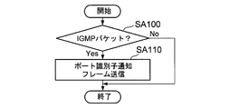
- FIG. 3 is a flowchart showing a flow of IGMP packet discrimination processing executed by the switching engine unit 520 of the switching hub 50.
- the switching engine unit 520 refers to the header portion of the packet written in the payload portion of the frame received via the downstream port, and determines whether or not the packet is an IGMP packet.
- Step SA100 the switching engine unit 520 reads the header portion of the packet written in the payload portion of the received frame, and determines whether or not the protocol type described in the header portion indicates IGMP. judge. If the protocol identifier indicates IGMP, the determination result in step SA100 is “Yes”, and if it indicates another protocol, the determination result in step SA100 is “No”.
- the switching engine unit 520 generates a port identifier notification frame for notifying the port identifier of the downstream port that has received the IGMP packet only when the determination result of step SA100 is “Yes”, to the router 60. Transmit (step SA110).
- an IGMP packet (specifically, IGMP Join) is written in the payload portion of the frame transmitted from the receiving device 40-1 to the switching hub 50 in this operation example. Accordingly, the determination result in step SA100 is “Yes”, and the port identifier notification frame in which the port identifier of the port that received the frame (port identifier of the port 512D-1) is written in the payload portion is transmitted from the switching hub 50 to the router 60. Sent to. Separately from the port identifier notification frame, a frame received from the receiving device 40-1 (a frame containing an IGMP packet) is also transferred to the router 60.
- FIG. 5 is a flowchart showing the flow of the switching hub control process executed by the routing engine unit 620 of the router 60.
- the routing engine unit 620 receives a frame via the downstream port (port 612D), it first writes in the header part of the frame whether or not the frame is a port identifier notification frame. The determination is made with reference to the type information (step SB100). Then, the routing engine unit 620 executes the processes after step SB110 only when the determination result of step SB100 is “Yes”. In this operation example, since the port identifier notification frame is first transmitted from the switching hub 50, the determination result in step SB100 is “Yes”, and the processing after step SB110 is executed.
- step SB110 determines whether or not another frame received from the transmission source of the port identifier notification frame includes an IGMP packet notifying participation in the multicast group (or leaving the multicast group). It is processing to do.
- the determination as to whether or not a packet included in another frame received from the transmission source of the port identifier notification frame is an IGMP packet notifying participation in the multicast group (or leaving the multicast group) Similar to the case of the conventional IGMP snooping, it may be performed by referring to the payload portion of the packet included in the frame.
- the routing engine unit 620 If the determination result in step SB110 is “Yes”, the routing engine unit 620 generates a port opening / closing instruction frame for instructing opening / closing of the downstream port according to the contents of the IGMP packet, and It transmits to the transmission source of the port identifier notification frame (step SB120). For example, when the packet included in another frame received from the transmission source of the port identifier notification frame is an IGMP packet (IGMP Join) for notifying participation in the multicast group, the routing engine unit 620 A port open / close instruction frame for instructing to open only the port indicated by the port identifier notified in the port identifier notification frame to the multicast group is generated and transmitted.
- IGMP Join IGMP Join
- the routing engine unit 620 sets the port indicated by the port identifier notified in the port identifier notification frame to the multicast notified of the departure.
- a port open / close instruction frame for instructing the group to be blocked is generated and transmitted.
- Step SB110 since the packet transmitted from the receiving device 40-1 via the switching hub 50 is IGMP Join, the determination result in Step SB110 is “Yes”, and the processing in Step SB120 is executed. That is, in this operation example, it is instructed to release only the port having the port number “1” to the multicast group notified of participation by the IGMP Join (in other words, to block other downstream ports). A port open / close instruction frame to that effect is transmitted from the router 60 to the switching hub 50.
- the control unit 540 of the switching hub 50 When receiving the port opening / closing instruction frame via the communication I / F unit 510 and the switching engine unit 520, the control unit 540 of the switching hub 50 opens / closes the downstream port (that is, the frame transfer control table) according to the contents of the frame. Update the stored contents).
- the downstream port that is, the frame transfer control table
- Update the stored contents As a result, among the four ports on the downstream side of the switching hub 50, only the port with the port number “1” (ie, port 512D-1) is opened to the multicast group, and the other downstream ports are blocked. The For this reason, even if transmission of the packet addressed to the multicast group is started from the transmission device 10 and the packet is transferred from the router 60 to the switching hub 50, the packet is received by the reception devices 40-2, 40-3 and 40-. 4 is not transferred, and no useless data stream is generated. The above is the operation of this embodiment.
- the process of determining whether or not the IGMP Join is performed with reference to the payload portion of the packet is performed.
- the packet is determined.
- the router 60 performs processing for determining whether the packet is IGMP Join by referring to the payload portion of the packet.
- the processing that refers to the header portion of the packet has a lower processing load than the processing that refers to the payload portion of the packet. Therefore, the switching hub 50 has a processing capability lower than that of a switching hub having an IGMP snooping function.
- the power consumption can be suppressed.
- no wasteful data stream is generated downstream of the switching hub 50 in the present embodiment. As described above, according to the present embodiment, it is possible to prevent a useless data stream from being generated downstream of the switching hub while suppressing power consumption in the switching hub.
- FIG. 6A a plurality of switching hubs (in FIG. 6A, four switching hubs 50A, 50B, 50C, and 50D) are directly connected to the router (in other words, , Each switching hub is connected to the router without any other switching hub).
- FIG. 6A illustration of the communication device upstream of the router 60 (for example, the transmission device 10 in FIG. 1) is omitted (the same applies to FIG. 6B).
- the second mode includes a plurality of switching hubs connected to a router via one or a plurality of other switching hubs as in the communication system 1C shown in FIG. 6B. It is an aspect.
- the switching hub 50B is connected to the router 60 via one other switching hub (switching hub 50A), and the switching hub 50C includes a plurality of other switching hubs (ie, switching hubs). It is connected to the router 60 via hubs 50B and 50A).
- each of the switching hubs 50A to 50D is caused to execute the IGMP packet discrimination process and the port opening / closing control process of FIG. 3, and the switching hub control process of FIG.
- the process to be executed at 60 generation of useless data streams can be avoided.
- a switching hub to which another switching hub is connected on the downstream side does not perform IGMP packet discrimination processing and port opening / closing control processing, and does not have an IGMP snooping function. Even if it is a hub (that is, a switching hub that does not perform multicast packet filtering), the switching hub can transfer the port identifier notification frame and the port open / close instruction frame. As long as the IGMP packet discrimination process and the port opening / closing control process can be executed, a useless data stream is not generated downstream of the downstream switching hub.
- the switching hub 50A does not perform the IGMP packet discrimination process and the port opening / closing control process and does not have an IGMP snooping function.
- Each of the switching hubs 50B to 50D is assumed to be capable of executing an IGMP packet discrimination process and a port opening / closing control process.
- the switching hub 50B notifies the router 60 of the port identifier of the port to which the receiving device 40B is connected. In response to the instruction, only the port is released to the multicast group.
- the router 60 Since the switching hubs 50C and 50D do not transmit IGMP Joins from the receiving devices connected to them, the router 60 does not perform the IGMP packet discrimination process and instructs the router 60 to open a port for the multicast group. It will never be done. In other words, the ports on the downstream side of the switching hubs 50C and 50D remain blocked from the multicast group.
- the frame including the packet is transferred to the switching hubs 50B and 50D.
- the frame is not transferred to the downstream side of the switching hub 50D.
- the switching hub 50B since only the port to which the receiving device 40B is connected is opened to the multicast group, the frame is transferred only through this port, and the switching hub 50B transfers to the switching hub 50C. The frame is not transferred.
- the port identifier of the downstream port that received the frame containing the IGMP packet is notified to the router 60 by transmitting the port identifier notification frame, but a predetermined area (
- the notification to the router 60 may be realized by adding and transferring the port identifier and the MAC address of the switching hub that notifies the port identifier to an option field.
- the MAC address of the notification source of the port identifier is additionally written in order to transmit the notification source to the router 60.
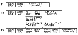
- the upstream switching hub is closer to the top of the predetermined area. What is necessary is just to make it add a port identifier and a MAC address hierarchically, such as adding a port identifier and a MAC address. For example, when the switching hub 50B of FIG. 6B transfers the frame F1 including the IGMP packet, the port identifier of the port that received the frame and the MAC address of the notification source of the port identifier (that is, the switching hub 50B) Frame F2 (see FIG.
- the MAC address is added to the header portion is transmitted to the switching hub 50A, and the switching hub 50A sends the port identifier of the port that received the frame and the MAC address of the notification source of the port identifier. What is necessary is just to make the router 60 transmit the frame F3 (see FIG. 7) in which the header portion is added (that is, the MAC address of the switching hub 50A).
- the switching hub 50 that has received the frame containing the IGMP packet is notified to the router 60 of the port identifier of the downstream port that has received the frame.
- the source communication address (MAC address or IP address) of the IGMP packet may be notified.
- each receiving device 40-k Each multicast join is associated with the port identifier of the downstream port of the switching hub that has received the frame including the IGMP Join based on the source address of the IGMP Join and the communication address notified together with the port identifier, and each multicast It becomes possible to appropriately open and close the port for the group.
- the packet included in the frame relayed by the switching hub that is the transmission source of the port identifier notification frame is for notifying participation in or leaving from the multicast group. Whether or not there is a router 60 is determined, and a port opening / closing instruction frame corresponding to the determination result is transmitted to the router 60.
- an IGMP packet for notifying the departure from the multicast group may not be defined. For this reason, of course, only the packet for notifying the participation in the multicast group may be set as the determination target in step SB110.
- the port is set to the multicast group when a certain time has elapsed since the reception of the packet.
- the router 60 may be caused to execute timer processing such as transmitting a port open / close instruction frame instructing blocking.
- the IGMP packet discrimination process in the switching hub 50 is executed by the ASIC (switching engine unit 520), and the port opening / closing control process is executed by the control unit 540 according to the firmware. That is, in the above-described embodiment, the IGMP packet determination process is realized by hardware, and the port opening / closing control process is realized by software. However, both may be realized by software (or hardware), IGMP packet discrimination processing may be realized by software, and port opening / closing control processing may be realized by hardware. Similarly, of course, the switching hub control process in the router 60 may be realized by hardware.
- the computer-readable recording medium such as a CD-ROM (Compact Disk-Read Only Memory)
- the firmware may be written and distributed, or the firmware may be distributed by downloading via a telecommunication line such as the Internet. This is because, by rewriting the firmware of the existing switching hub with the firmware thus distributed, the same function as the switching hub 50 can be given to the existing switching hub.
- the firmware that implements the switching hub control process may be distributed by writing in a computer-readable recording medium, or may be distributed by downloading via an electric communication line such as the Internet.
- the firmware that is, the program for causing the control unit 540 to execute the port opening / closing control processing
- the firmware stored in the storage unit 530 of the switching hub 50 in the above embodiment is also written and distributed on a computer-readable recording medium. It may also be distributed by downloading via a telecommunication line.
Landscapes
- Engineering & Computer Science (AREA)
- Computer Networks & Wireless Communication (AREA)
- Signal Processing (AREA)
- Data Exchanges In Wide-Area Networks (AREA)
- Small-Scale Networks (AREA)
Abstract
本発明は、スイッチングハブにおける電力消費を抑えつつ、無駄なデータストリームが発生しないようにすることを目的とする。スイッチングハブ50においては、下流側から受信したパケットのヘッダのみに基づいてそのパケットがIGMPパケットであるか否かを判定し、IGMPパケットである場合にはそのパケットを受信したポートのポート識別子をルータ60へ通知する処理と、ルータ60からの指示にしたがって下流側ポートの開閉を行う処理を実行させる。一方、ルータ60には、上記ポート識別子の通知を受けた場合に、その通知元により中継されたパケットがIGMPJoinであるか否かをそのパケットのペイロード部を参照して判定し、その判定結果に応じて上記通知元のスイッチングハブに対して、ポートの開閉を指示する処理を実行させる。
Description
本発明は、データの中継技術に関し、特に、マルチキャストされるデータの中継技術に関する。
通信システムを構築するために用いられる中継装置の一例として、ルータやスイッチングハブが挙げられる。ルータとは、OSI参照モデルの第1層(物理層)から第3層(ネットワーク層)までの接続を行う中継装置であり、インターネットなどのIP(Internet Protocol)網を介して他のルータとデータの送受信を行う役割を担う。一方、スイッチングハブとは、第1層から第2層(データリンク層)までの接続を行う中継装置であって、データ通信の終端に位置する通信端末(例えば、パーソナルコンピュータなど)を通信網に収容する役割を担う。ここで、第n層の接続を行うとは、第n層の通信プロトコルにしたがってデータの転送制御を行うことをいう。
例えば、第2層のデータブロックであるフレームのヘッダ部には、そのフレームの送信元および送信先の通信装置(中継装置や通信端末)のハードウェアアドレスであるMAC(Media Access Control)アドレスがそのフレームの送信元アドレスおよび送信先アドレスとして書き込まれ、そのペイロード部には第3層のデータブロックであるパケットが書き込まれる。そして、パケットのヘッダ部には、第3層においてその送信元および送信先を識別するための通信アドレスであるIPアドレスがそのパケットの送信元アドレスおよび送信先アドレスとして書き込まれる。ルータやスイッチングハブでは、受信したデータブロックのヘッダ部に書き込まれている送信先アドレスに基づいてそのデータブロックの転送制御が行われる。以下、図8を参照しつつ、ルータやスイッチングハブが行うデータブロックの転送制御について説明する。
図8は、ルータおよびスイッチングハブを含む通信システムの一例を示す図である。図8に示す通信システムでは、送信装置10から受信装置40-k(k=1~4)へのデータの送信が行われる。なお、図8では詳細な図示は省略したが、ルータ20と送信装置10との間には、ルータ20が接続されているIP網と、このIP網と送信装置10とを接続する他のルータが存在する。ルータ20にはスイッチングハブ30が接続されており、スイッチングハブ30には送信装置10から送信されるデータを受信する通信端末(受信装置40-1~40-4)が接続されている。
図8のルータ20は、送信装置10から受信装置40-1へ宛てて送信されたパケットを内包したフレーム(当該パケットがペイロード部に書き込まれているフレーム)を受信すると、そのパケットのヘッダ部を参照し、その送信先IPアドレスが自装置の配下の通信端末に割り当てられているIPアドレスである場合には、当該フレームをスイッチングハブ30へと転送する。逆に、受信したフレームに内包されているパケットが配下の通信端末へ宛てて送信されたものではない場合には、ルータ20は、ルーティングテーブルの格納内容にしたがって当該フレームを他のルータへと転送する。
図8のスイッチングハブ30は、各々他の通信装置(ルータや他のスイッチングハブ、通信端末)に接続される複数のポートを有しており、これら複数のポートの各々に対応付けてそのポートの接続先の通信装置のMACアドレスを記憶している。そして、スイッチングハブ30は、何れかのポートを介してフレームを受信すると、そのフレームのヘッダ部に書き込まれている送信先MACアドレスを参照し、当該フレームをその送信先MACアドレスに対応するポートへと出力するのである。なお、以下では、スイッチングハブが有する複数のポートのうち、ルータに接続されているポート(或いは、他のスイッチングハブを介してルータに接続されているポート)を「上流側ポート」と呼び、その他のポート(図8では、受信装置40-kが接続されているポート)を「下流側ポート」と呼ぶ。
このように、スイッチングハブは、各ポートに対応付けたMACアドレスと受信したフレームの送信先MACアドレスとに基づいてフレームの転送制御を行う。このため、IPマルチキャストされたパケットを内包したフレームを上流側から受信した場合に、当該スイッチングハブの下流側に無駄なデータストリームを発生させてしまう、といった問題点がある。その理由は、以下の通りである。IPマルチキャストとは、特定の通信端末に宛ててパケットを送信するのではなく、そのパケットの受信を表明した通信端末のグループ(マルチキャストグループ)に宛ててパケットを送信する態様である。IPマルチキャストにおいては、パケットの送信先アドレスはマルチキャストグループに割り当てられたIPアドレスとなる。同様に、IPマルチキャストされたパケットを内包したフレームの送信先MACアドレスも、特定の通信端末のMACアドレスではなく、マルチキャストグループのIPアドレスから生成されるマルチキャストMACアドレスが用いられる。
マルチキャストMACアドレスはマルチキャストグループのIPアドレスから生成されるものであるから、スイッチングハブの各ポートに対応付けられているMACアドレスの何れとも一致しない。このように、各ポートに対応付けられているMACアドレスの何れにも一致しない送信先MACアドレスを有するフレームを受信した場合、スイッチングハブでは、当該フレームを全ての下流側ポートへ送出する処理(フラッディング)が実行される。例えば、図8に示す通信システムにおいて、送信装置10があるマルチキャストグループ宛てにパケットを送信しており、受信装置40-1のみがそのマルチキャストグループに参加している場合であっても、スイッチングハブ30においてフラッディングが行われるため、受信装置40-2~40-4に対しても上記マルチキャストグループ宛のパケットを内包したフレームの転送が行われる。受信装置40-2~40-4は、マルチキャストグループには参加していないのであるから、これらに対する当該フレームの転送は無駄なデータストリームに他ならない。これが、IPマルチキャストされたパケットを内包したフレームを受信した場合にスイッチングハブの下流で無駄なデータストリームが発生する理由である。
このような問題の発生を回避するための技術が従来より種々提案されており、その一例としてはIGMP(Internet Group Management Protocol)スヌーピングが挙げられる。ここで、IGMPとは、マルチキャスト通信を実現するための通信プロトコルの1つであって、マルチキャストグループへの参加を通信端末からルータに通知するための通信プロトコルである。ルータは、IGMPにしたがって配下の通信端末からマルチキャストグループへの参加を通知されると、自装置の配下にマルチキャストグループに参加する通信端末があることを示す情報を記憶する処理(以下、参加管理処理と呼ぶ。また、マルチキャストグループからの離脱通知に応じて当該情報を削除する処理と合わせて、参加/離脱管理処理と呼ぶ)を行い、以後、上流側からそのマルチキャストグループ宛に送信されてくるパケットの下流側への転送を開始する。スヌーピングとは、「覗き見する」という意味であり、IGMPスヌーピング機能を備えたスイッチングハブは、下流側ポートにより受信したフレームに内包されているパケットのペイロード部を参照し、そのパケットがマルチキャストグループへの参加をルータに通知するためのパケット(IGMPJoin)であれば、そのマルチキャストグループを示す識別子(例えば、マルチキャストMACアドレス:以下、マルチキャストグループ識別子)を当該ポートに対応付けて記憶する。そして、上流側から転送されてくるフレームの送信先MACアドレスが上記マルチキャストグループ識別子に一致する場合には、当該マルチキャストグループ識別子を対応付けた下流側ポートへのみそのフレームを送出し、他の下流側ポートには当該フレームを送出しないようにするのである。これにより、無駄なデータストリームの発生が回避されるのである。なお、IGMPスヌーピング機能を有するスイッチングハブに関する先行技術文献としては、特許文献1が挙げられる。
ところで、近年では、環境問題への意識の高まりに起因して電子機器の消費電力をその機能に応じた最低限の値に抑えることが大きな課題となっており、所謂省エネ法などにより消費電力に法規制が課されている場合もある。スイッチングハブなどの通信装置についても、このような風潮は例外ではない(「エネルギー使用の合理化に関する法律施行令 第21条特定機器」(日本国)参照)。前述したように、無駄なデータストリームが発生しないようにするにはスイッチングハブにIGMPスヌーピング機能を実装する必要があるが、IGMPスヌーピング機能を実装する場合には、その機能を実装しない場合よりも高い処理能力が必要となり、自ずから消費電力が上昇してしまう。
本発明は上記課題に鑑みて為されたものであり、スイッチングハブにおける電力消費を抑えつつ、無駄なデータストリームが発生しないようにすることを可能にする技術を提供することを目的とする。
本発明は上記課題に鑑みて為されたものであり、スイッチングハブにおける電力消費を抑えつつ、無駄なデータストリームが発生しないようにすることを可能にする技術を提供することを目的とする。
上記課題を解決するために本発明は、下流側の通信装置が各々接続される複数の下流側ポートと上流側の通信装置に接続される上流側ポートとを備え、各ポートを介して受信したフレームの転送制御をそのフレームの送信先アドレスに基づいて行う1または複数のスイッチングハブと、前記1または複数のスイッチングハブの上流に位置するルータと、を含む通信システムにおいて、前記1または複数のスイッチングハブの各々は、前記複数の下流側ポートの各々について、その下流側ポートにより受信したフレームに内包されているパケットがマルチキャスト通信を実現するための所定の通信プロトコルにしたがって送信されたものであるか否かをそのパケットのヘッダ部を参照して判定し、当該通信プロトコルにしたがって送信されたものであると判定した場合には、当該下流側ポートを示すポート識別子を前記ルータへ通知する第1の処理と、前記ルータからの指示にしたがって下流側ポートの開閉を行う第2の処理とを実行し、前記ルータは、前記1または複数のスイッチングハブの何れかからポート識別子を通知された場合に、その通知元であるスイッチングハブにより当該ルータへ中継されたパケットがマルチキャストグループへの参加を前記通信プロトコルにしたがって通知するためのものであるか否かを、当該パケットのペイロード部を参照して判定し、マルチキャストグループへの参加を通知するためのものであると判定した場合には、当該ポート識別子の通知元のスイッチングハブに対して、当該ポート識別子の示す下流側ポートのみを当該マルチキャストグループに対して開放することを指示するよう構成される通信システム、を提供する。
従来のIGMPスヌーピング機能を備えたスイッチングハブにおいては、パケットのペイロード部を参照してIGMPJoinであるか否かを判定する処理が行われていたのであるが、本通信システムに含まれるスイッチングハブにおいてはパケットのヘッダ部を参照している。パケットのヘッダ部を参照する処理は、パケットのペイロード部を参照する処理に比較して処理負荷が低い。このため、上記通信システムに含まれるスイッチングハブは、IGMP機能を備えた従来のスイッチングハブよりも処理能力の低いもので充分であり、その消費電力を抑えることができる。なお、パケットのペイロード部を参照してIGMPJoinであるか否かを判定する処理はルータで行われ、ルータは、この判定結果に応じてスイッチングハブに下流側ポートの開閉を指示する。スイッチングハブでは、ルータからの指示に応じて下流側ポートの開閉が行われるため、スイッチングハブの下流側に無駄なデータストリームが発生することはない。
また、上記課題を解決するために、本発明は、1または複数の他のスイッチングハブを介してルータとの間で、または他のスイッチングハブを介さずにルータとの間でフレームを送受信するための上流側ポートを備えるとともに、下流側の通信装置との間でフレームを送受信するための下流側ポートを複数備え、各ポートを介して受信したフレームの転送制御をそのフレームの送信先アドレスに基づいて行うよう構成されるスイッチングハブにおいて、前記複数の下流側ポートの各々について、その下流側ポートを介して受信したフレームに内包されているパケットがマルチキャスト通信を実現するための所定の通信プロトコルにしたがって送信されたものであるか否かをそのパケットのヘッダ部を参照して判定し、前記所定の通信プロトコルにしたがって送信されたものであると判定した場合には、当該下流側ポートを示すポート識別子を前記ルータへ通知する通知手段と、前記ルータからの指示にしたがって下流側ポートの開閉を行うポート開閉制御手段とを有するスイッチングハブを提供する。なお、本発明の別の態様においては、コンピュータを上記通知手段およびポート開閉制御手段として機能させるプログラムを提供することが考えられる。
また、上記課題を解決するために、本発明は、1または複数のスイッチングハブを介して受信したパケットを他のルータへ転送する一方、当該他のルータから受信したパケットを前記1または複数のスイッチングハブを介してその宛先へ転送するよう構成されるルータにおいて、前記1または複数のスイッチングハブの何れかから、マルチキャスト通信を実現するために所定の通信プロトコルにしたがって送信されたパケットを受信したことを示す通知であって、当該パケットを受信したポートを示すポート識別子を知らせる旨の通知を受信した場合に、当該パケットがマルチキャストグループへの参加を前記所定の通信プロトコルにしたがって当該ルータへ通知するために送信されたものであるか否かを、当該パケットのペイロード部を参照して判定する判定手段と、マルチキャストグループへの参加を通知するためのものであると前記判定手段により判定された場合には、前記ポート識別子の通知を行ったスイッチングハブに対して、当該ポート識別子の示すポートのみを当該マルチキャストグループに対して開放することを指示するポート開閉指示手段とを有するルータを提供する。なお、本発明の別の態様においては、コンピュータを上記判定手段およびポート開閉指示手段として機能させるプログラムを提供することが考えられる。
以下、図面を参照しつつ本発明の実施形態について説明する。
(A:第1実施形態)
(A-1:構成)
図1は、本発明の第1実施形態の通信システム1Aの構成例を示す図である。図1においては、図8におけるものと同一の構成要素には同一の符号が付されている。図1と図8とを対比すれば明らかなように、この通信システム1Aは、ルータ20に代えてルータ60を設けた点と、スイッチングハブ30に代えてスイッチングハブ50を設けた点が図8に示す通信システムと異なる。この通信システム1Aにおいては、あるマルチキャストグループ宛に送信装置10から送信されるパケットを受信装置40-k(k=1~4)の何れか1台が受信する場合であっても、ルータ60とスイッチングハブ50とに本実施形態の特徴を顕著に示す処理を行わせて両者を協動させることで、スイッチングハブ50の下流側(すなわち、スイッチングハブ50と他の受信装置40-kの間)に無駄なデータストリームが発生しないようにしているのである。以下、本実施形態の特徴を顕著に示すスイッチングハブ50およびルータ60を中心に説明する。
(A:第1実施形態)
(A-1:構成)
図1は、本発明の第1実施形態の通信システム1Aの構成例を示す図である。図1においては、図8におけるものと同一の構成要素には同一の符号が付されている。図1と図8とを対比すれば明らかなように、この通信システム1Aは、ルータ20に代えてルータ60を設けた点と、スイッチングハブ30に代えてスイッチングハブ50を設けた点が図8に示す通信システムと異なる。この通信システム1Aにおいては、あるマルチキャストグループ宛に送信装置10から送信されるパケットを受信装置40-k(k=1~4)の何れか1台が受信する場合であっても、ルータ60とスイッチングハブ50とに本実施形態の特徴を顕著に示す処理を行わせて両者を協動させることで、スイッチングハブ50の下流側(すなわち、スイッチングハブ50と他の受信装置40-kの間)に無駄なデータストリームが発生しないようにしているのである。以下、本実施形態の特徴を顕著に示すスイッチングハブ50およびルータ60を中心に説明する。
図2は、スイッチングハブ50の構成を示すブロック図である。図2に示すように、スイッチングハブ50は、通信インタフェース(以下、I/F)部510、スイッチングエンジン部520、記憶部530および制御部540を有している。制御部540は、例えばCPU(Central Processing Unit)であり、記憶部530に格納されているファームウェアにしたがって各部の作動制御を中枢的に行う。このファームウェアにしたがって制御部540が実行する処理については後に詳細に説明する。
通信I/F部510は、他の通信装置との間でフレームの授受を行うインタフェースであり、各々他の通信装置が接続される複数のポート(図2では、ポート512Uおよび512D-1~512D-4の5つのポート)を有している。本実施形態では、これら複数のポートの各々を介してその接続先の通信装置との間でフレームの授受が行われる。図2のポート512Uはルータ60に接続されている上流側ポートであり、ポート512D-k(k=1~4)は各々受信装置40-kに接続された下流側ポートである。これら複数のポートの各々には、各ポートを一意に識別するポート識別子が予め割り当てられている。本実施形態では、ポート512Uにはポート番号“0”が、ポート512D-k(k=1~4)には、ポート番号“k”が割り当てられており、これらポート番号がポート識別子の役割を果たす。
スイッチングエンジン部520は、例えばASIC(Application Specific Integrated Circuit)である。このスイッチングエンジン部520は、記憶部530に格納されているフレーム転送制御テーブルの格納内容を参照しつつ、通信I/F部510の各ポートを介して受信したフレームの送信先MACアドレスに基づいて、前述したフレームの転送制御を行う。加えて、本実施形態のスイッチングエンジン部520は、下流側ポートを介してフレームを受信した場合に、そのフレームの転送制御に先立って、図3に示すIGMPパケット判別処理を実行する。詳細については動作例において明らかにするが、このIGMPパケット判別処理は、下流側ポートを介して受け取ったフレームがIGMPパケット(IGMPJoinであるか否かは問わない)を内包したものである場合に、当該フレームを受信したポートのポート識別子をルータ60へ通知する処理である。本実施形態では、ルータ60へのポート識別子の通知には、専用のフレーム(以下、ポート識別子通知フレーム)が用いられる。このポート識別子通知フレームのヘッダ部には、当該フレームの送信元(すなわち、スイッチングハブ50)および送信先(ルータ60)のMACアドレスに加えて当該フレームがポート識別子通知フレームであることを示す種別情報が書き込まれる。また、ポート識別子通知フレームのペイロード部には、IGMPパケットを内包したフレームを受信した下流側ポートのポート識別子が書き込まれる。
記憶部530は、図2では詳細な図示を省略したが、例えばRAM(Random Access Memory)などの揮発性メモリとEPROM(Erasable Programmable ROM)などの不揮発性メモリとを含んでいる。上記ファームウェアは不揮発性メモリに記憶され、揮発性メモリには上記フレーム転送制御テーブルが格納される。また、この揮発性メモリは、上記ファームウェアを実行する際のワークメモリとして制御部540によって利用されるとともに、前述したフレーム転送制御の際にフレームを一時的に蓄積しておくバッファの役割も果たす。
図2のフレーム転送制御テーブルには、各ポートのポート識別子に対応付けてそのポートに接続されている通信装置のMACアドレスが登録されている。なお、フレーム転送制御テーブルへのMACアドレスおよびポート識別子の登録については周知の手法を採用すれば良い。また、このフレーム転送制御テーブルには、上記各ポートの接続先の通信装置がマルチキャストグループに参加している場合に、そのポートのポート識別子に対応付けてそのマルチキャストグループのマルチキャストグループ識別子が登録される。スイッチングエンジン部520は、通信I/F部510から受け取ったフレームがマルチキャストグループ宛のものである場合には、そのマルチキャストグループのマルチキャストグループ識別子に対応付けてフレーム転送制御テーブルに登録されているポート識別子の示すポートのみから当該フレームを出力し、これにより無駄なデータストリームの発生を回避するのである。
このようにポート識別子と対応付けてマルチキャストグループ識別子をフレーム転送制御テーブルに登録することは、そのマルチキャストグループ宛のフレームを当該ポート識別子の示すポートを通過させるようにすることであるから、「マルチキャストグループに対してポートを開放する」という。逆に、フレーム転送制御テーブルに互いに対応付けて登録されているポート識別子およびマルチキャストグループ識別子の組を削除すること、或いは、このような登録を行わないこと、を「マルチキャストグループに対してポートを閉塞する」という。詳細については後述するが、マルチキャストグループに対してポートの開放(または閉塞)を行うポート開閉制御処理はルータ60からの指示に応じて制御部540が実行する。ルータ60からのポートの開閉指示についても新たに定義された専用のフレーム(ポート開閉指示フレーム)が用いられる。
以上がスイッチングハブ50の構成である。
以上がスイッチングハブ50の構成である。
次いで、図4を参照しつつルータ60の構成を説明する。図4は、ルータ60の構成を示すブロック図である。図4に示すように、ルータ60は、通信I/F部610、ルーティングエンジン部620および記憶部630を有している。通信I/F部610は、図2の通信I/F部510と同様に、複数のポート(図4では、ポート612Uおよび612Dの2つのポート)を有している。図4のポート612UはIP網(図示略)に接続される上流側ポートであり、ポート612Dはスイッチングハブ50に接続される下流側ポートである。なお、本実施形態の通信I/F部610は、下流側ポートを1つだけ有しているが複数の下流側ポートを有していても勿論良い。
ルーティングエンジン部620は、CPUとRAMとを含んでいる(図4では、何れも図示略)。上記CPUは、記憶部630に格納されているファームウェア(プログラム)にしたがって、記憶部630に記憶されているルーティングテーブルと通信I/F部610から引渡されるフレームのペイロード部に書き込まれているパケットの送信先IPアドレスとに基づいたパケット転送制御やマルチキャストグループへの参加/離脱管理処理を行う。パケット転送制御処理については、一般的なルータが行うものと特段代わったところはないため説明を省略する。なお、本実施形態では、ルーティングエンジン部620をCPUとRAMにより構成したが、ASICで構成しても勿論良い。
加えて、本実施形態のルーティングエンジン部620のCPUは、上記パケット転送制御処理やマルチキャストグループへの参加/離脱管理処理に先立って、図5に示すスイッチングハブ制御処理を上記ファームウェアにしたがって実行する。詳細については後述するが、このスイッチングハブ制御処理では、まず、通信I/F部610から引き渡されたフレームがポート識別子通知フレームであるか否かが判定され、さらに、当該ポート識別子通知フレームの送信元(すなわち、スイッチングハブ50)から受信した他のフレームに内包されているパケットがマルチキャストグループへの参加(或いは、マルチキャストグループからの離脱)を通知するためのものであるか否かが判定される。そして、これらの要件を全て満たした場合には、ルーティングエンジン部620は、前述したポート開閉指示フレームを上記ポート識別子通知フレームの送信元へ返信するのである。つまり、上記ファームウェアにしたがって作動するルーティングエンジン部620は、上記各判定を行う判定手段、および、ポート開閉指示フレームを上記ポート識別子通知フレームの送信元へ返信し、下流側ポートの開閉を指示するポート開閉指示手段として機能するのである。このポート開閉指示フレームのヘッダ部には、送信元(すなわち、ルータ60)および送信先(すなわち、スイッチングハブ50)のMACアドレスとともに、当該フレームがポート開閉指示フレームであることを示す種別情報が書き込まれる。また、ポート開閉指示フレームのペイロード部には、上記IGMPパケットにより参加(或いは離脱)を通知されたマルチキャストグループを示すマルチキャストグループ識別子と、そのマルチキャストグループに対して開放(または閉塞)するべきポートのポート識別子(すなわち、上記ポート識別子通知フレームにより通知されたポート識別子)と、当該ポートを開放するのかそれとも閉塞するのかを指示する指示子と、が書き込まれる。
以上がルータ60の構成である。
以上がルータ60の構成である。
(A-2:動作)
次いで、図1に示す通信システム1Aにおいて、送信装置10からマルチキャストされるデータを受信装置40-1が受信する場合を例にとって、スイッチングハブ50およびルータ60が実行する動作を説明する。
次いで、図1に示す通信システム1Aにおいて、送信装置10からマルチキャストされるデータを受信装置40-1が受信する場合を例にとって、スイッチングハブ50およびルータ60が実行する動作を説明する。
受信装置40-1のユーザは、送信装置10からマルチキャストされるデータの受信を所望する場合、まず、そのマルチキャストグループへの参加を指示する旨の操作を受信装置40-1に対して行う。このような操作が為されると、受信装置40-1の制御部(図示略)は、上記マルチキャストグループへの参加を通知する旨のIGMPパケット(すなわち、IGMPJoin)を生成する。このようにして生成されたIGMPパケットは、受信装置40-1内で第2層のデータブロックであるフレームのペイロード部に書き込まれ、ルータ60へ宛てて送信される。このフレームのヘッダ部には、その送信元MACアドレスとして受信装置40-1のMACアドレスが、その送信先MACアドレスとしてルータ60のMACアドレスが書き込まれている。
このようにして受信装置40-1から送信されたフレームは、スイッチングハブ50においてその受信装置40-1を接続するポート(本動作例では、ポート512D-1)を介してスイッチングエンジン部520に入力される。前述したように、スイッチングエンジン部520は、下流側ポートを介してフレームを受信した場合には、図3に示すIGMPパケット判別処理を実行し、その後、その宛先に基づいたフレーム転送制御を行う。なお、上流側ポートを介してフレームを受信した場合には、スイッチングエンジン部520は、IGMPパケット判別処理を行うことなく、その宛先に基づくフレーム転送制御を行う。本動作例においては、スイッチングハブ50は下流側ポートであるポート512D-1を介してフレームを受信するのであるから、フレーム転送制御に先立って、図3のIGMPパケット判別処理が実行される。
図3は、スイッチングハブ50のスイッチングエンジン部520が実行するIGMPパケット判別処理の流れを示すフローチャートである。図3に示すように、スイッチングエンジン部520は、下流側ポートを介して受信したフレームのペイロード部に書き込まれているパケットのヘッダ部を参照し、当該パケットがIGMPパケットであるか否かを判定する(ステップSA100)。具体的には、スイッチングエンジン部520は、受信したフレームのペイロード部に書き込まれているパケットのヘッダ部を読み出し、そのヘッダ部に記述されているプロトコル種別がIGMPを示すものであるか否かを判定する。このプロトコル識別子がIGMPを示すものである場合には、ステップSA100の判定結果は“Yes”になり、その他のプロトコルを示すものである場合には、ステップSA100の判定結果は“No”になる。そして、スイッチングエンジン部520は、ステップSA100の判定結果が“Yes”である場合にのみ、IGMPパケットを受信した下流側ポートのポート識別子を通知するためのポート識別子通知フレームを生成し、ルータ60に送信する(ステップSA110)。
前述したように、本動作例において受信装置40-1からスイッチングハブ50へ送信されるフレームのペイロード部には、IGMPパケット(具体的には、IGMPJoin)が書き込まれている。したがって、上記ステップSA100の判定結果は“Yes”になり、当該フレームを受信したポートのポート識別子(ポート512D-1のポート識別子)をペイロード部に書き込んだポート識別子通知フレームがスイッチングハブ50からルータ60へ送信される。また、このポート識別子通知フレームとは別個に、受信装置40-1から受信したフレーム(IGMPパケットを内包したフレーム)のルータ60への転送も行われる。
図5は、ルータ60のルーティングエンジン部620が実行するスイッチングハブ制御処理の流れを示すフローチャートである。図5に示すように、ルーティングエンジン部620は、下流側ポート(ポート612D)を介してフレームを受信すると、まず、そのフレームがポート識別子通知フレームであるか否かをそのフレームのヘッダ部に書き込まれている種別情報を参照して判定する(ステップSB100)。そして、ルーティングエンジン部620は、ステップSB100の判定結果が“Yes”である場合にのみ、ステップSB110以降の処理を実行する。本動作例においてスイッチングハブ50からまず、ポート識別子通知フレームが送信されてくるのであるから、ステップSB100の判定結果は“Yes”になり、ステップSB110以降の処理が実行される。
ステップSB110の処理は、ポート識別子通知フレームの送信元から受信した他のフレームが、マルチキャストグループへの参加(或いはマルチキャストグループからの離脱)を通知するIGMPパケットを内包したものであるか否かを判定する処理である。ここで、ポート識別子通知フレームの送信元から受信した他のフレームに内包されているパケットがマルチキャストグループへの参加(或いはマルチキャストグループからの離脱)を通知するIGMPパケットであるか否かの判定は、従来のIGMPスヌーピングにおける場合と同様に、そのフレームに内包されているパケットのペイロード部を参照して行えば良い。
そして、ステップSB110の判定結果が“Yes”である場合には、ルーティングエンジン部620は、上記IGMPパケットの内容に応じて下流側ポートの開閉を指示する旨のポート開閉指示フレームを生成し、上記ポート識別子通知フレームの送信元へ宛てて送信する(ステップSB120)。例えば、ポート識別子通知フレームの送信元から受信した他のフレームに内包されているパケットが、マルチキャストグループへの参加を通知する旨のIGMPパケット(IGMPJoin)である場合には、ルーティングエンジン部620は、上記ポート識別子通知フレームにて通知されたポート識別子の示すポートのみをそのマルチキャストグループに対して開放することを指示する旨のポート開閉指示フレームを生成して送信する。一方、マルチキャストグループからの離脱を通知する旨のIGMPパケットである場合には、ルーティングエンジン部620は、上記ポート識別子通知フレームにて通知されたポート識別子の示すポートを、当該離脱を通知されたマルチキャストグループに対して閉塞することを指示する旨のポート開閉指示フレームを生成して送信する。
本動作例では、スイッチングハブ50を介して受信装置40-1から送信されてくるパケットはIGMPJoinであるから、ステップSB110の判定結果は“Yes”になり、ステップSB120の処理が実行される。つまり、本動作例では、ポート番号“1”のポートのみを上記IGMPJoinにて参加通知されたマルチキャストグループに対して開放すること(換言すれば、他の下流側ポートを閉塞すること)を指示する旨のポート開閉指示フレームがルータ60からスイッチングハブ50へ送信される。
スイッチングハブ50の制御部540は、通信I/F部510およびスイッチングエンジン部520を介してポート開閉指示フレームを受信すると、当該フレームの内容にしたがって下流側ポートの開閉(すなわち、フレーム転送制御テーブルの格納内容の更新)を行う。その結果、スイッチングハブ50の下流側の4つのポートのうち、ポート番号“1”のポート(すなわち、ポート512D-1)のみが上記マルチキャストグループに対して開放され、他の下流側ポートは閉塞される。このため、送信装置10から上記マルチキャストグループ宛のパケットの送信が開始され、当該パケットがルータ60からスイッチングハブ50へと転送されても、そのパケットが受信装置40-2、40-3および40-4に転送されることはなく、無駄なデータストリームが発生することはない。
以上が本実施形態の動作である。
以上が本実施形態の動作である。
従来のIGMPスヌーピング機能を備えたスイッチングハブにおいては、パケットのペイロード部を参照してIGMPJoinであるか否かを判定する処理が行われていたのであるが、本実施形態のスイッチングハブ50においてはパケットのヘッダ部を参照しており、パケットのペイロード部を参照してIGMPJoinであるか否かを判定する処理はルータ60で行われる。パケットのヘッダ部を参照する処理は、パケットのペイロード部を参照する処理に比較して処理負荷が低く、このため、スイッチングハブ50として、IGMPスヌーピング機能を備えたスイッチングハブよりも処理能力の低いものを用いることができ、その消費電力を抑えることができる。また、本実施形態においてスイッチングハブ50の下流に無駄なデータストリームが発生しないことは前述した通りである。このように、本実施形態によれば、スイッチングハブにおける電力消費を抑えつつ、そのスイッチングハブよりも下流側に無駄なデータストリームが発生しないようにすることが可能になる。
(B:第2実施形態)
上述した第1実施形態の通信システム1Aでは、ルータ60にスイッチングハブが1台だけ接続されていたが、複数のスイッチングハブがルータ60の下流に接続されている態様も勿論考えられる。本実施形態は、ルータ60の下流に複数のスイッチングハブが接続されている点が、上述した第1実施形態と異なる。
上述した第1実施形態の通信システム1Aでは、ルータ60にスイッチングハブが1台だけ接続されていたが、複数のスイッチングハブがルータ60の下流に接続されている態様も勿論考えられる。本実施形態は、ルータ60の下流に複数のスイッチングハブが接続されている点が、上述した第1実施形態と異なる。
ここで、ルータ60の下流に複数のスイッチングハブが接続される態様の具体例としては、以下の2つの態様が考えられる。第1に、図6Aに示す通信システム1Bのように、複数のスイッチングハブ(図6Aでは、スイッチングハブ50A、50B、50Cおよび50Dの4台)が直接ルータに接続されている態様(換言すれば、各スイッチングハブが他のスイッチングハブを介さずにルータに接続されている態様)である。なお、図6Aでは、ルータ60よりも上流の通信装置(例えば、図1の送信装置10)の図示を省略した(図6Bも同様)。そして、第2の態様は、図6Bに示す通信システム1Cのように、複数のスイッチングハブに、1台または複数台の他のスイッチングハブを介してルータに接続されているものが含まれている態様である。例えば、図6Bにおいて、スイッチングハブ50Bは、1台の他のスイッチングハブ(スイッチングハブ50A)を介してルータ60に接続されており、スイッチングハブ50Cは、複数台の他のスイッチングハブ(すなわち、スイッチングハブ50Bおよび50A)を介してルータ60に接続されている。
図6Aおよび図6Bに示す何れの接続態様においても、図3のIGMPパケット判別処理およびポート開閉制御処理をスイッチングハブ50A~50Dの各々に実行させ、かつ、図5に示すスイッチングハブ制御処理をルータ60に実行させることで、無駄なデータストリームの発生を回避することができる。なお、図6Bに示す接続態様において、下流側に他のスイッチングハブが接続されているスイッチングハブが、IGMPパケット判別処理およびポート開閉制御処理を行わず、また、IGMPスヌーピング機能も有してないスイッチングハブ(すなわち、マルチキャストパケットのフィルタリングを行わないスイッチングハブ)であっても、そのスイッチングハブがポート識別子通知フレームおよびポート開閉指示フレームを転送することができるものであり、さらに下流のスイッチングハブが図3のIGMPパケット判別処理およびポート開閉制御処理を実行可能なものであれば、当該下流側のスイッチングハブの下流には無駄なデータストリームは発生しない。
例えば、図6Bに示す態様において、スイッチングハブ50AはIGMPパケット判別処理およびポート開閉制御処理を行わず、また、IGMPスヌーピング機能も有してないものであるとする。そして、スイッチングハブ50B~50Dは、何れも、IGMPパケット判別処理およびポート開閉制御処理を実行可能なものであるとする。この場合において、スイッチングハブ50Bに接続されている受信装置40BのみがIGMPJoinを送信すると、スイッチングハブ50Bは、受信装置40Bが接続されているポートのポート識別子をルータ60へ通知し、ルータ60からの指示に応じて当該ポートのみをそのマルチキャストグループに開放する。また、スイッチングハブ50Cおよび50Dは、各々の接続先の受信装置からIGMPJoinは送信されてこないのであるから、上記IGMPパケット判別処理を行うことはなく、そのマルチキャストグループに対するポートの開放をルータ60から指示されることはない。つまり、スイッチングハブ50Cおよび50Dの下流側の各ポートは上記マルチキャストグループに対して閉塞されたままである。
このような状況で上記マルチキャストグループ宛のパケットの送信が開始されると、スイッチングハブ50Aでは、マルチキャストパケットのフィルタリングは行われないため、当該パケットを内包したフレームは、スイッチングハブ50Bと50Dに転送される。しかし、スイッチングハブ50Dでは、上記マルチキャストグループに対する下流側ポートの開放は行われていないため、上記フレームがスイッチングハブ50Dの下流側に転送されることはない。一方、スイッチングハブ50Bでは、受信装置40Bが接続されているポートのみが上記マルチキャストグループに開放されているため、このポートを介してのみ当該フレームの転送が行われ、スイッチングハブ50Bからスイッチングハブ50Cに上記フレームが転送されることはない。このように、最上流のスイッチングハブ50Aがマルチキャストパケットのフィルタリングを行わないものであっても、その下流側のスイッチングハブ50B、50Cおよび50Dの下流には無駄なデータストリームは発生しないのである。
このように、ルータの下流に複数のスイッチングハブが接続されている場合においても、IGMPスヌーピングをスイッチングハブのみで行う場合に比較して各スイッチングハブの処理負荷を軽減しつつ、無駄なデータストリームが発生することを防止することができる。このため、IGMPスヌーピングを各スイッチングハブに実行させる場合に比較して各スイッチングハブの処理能力を低く抑えることができ、その電力消費を抑えることが可能になる。
(C:変形)
以上、本発明の第1および第2実施形態について説明したが、これら実施形態を以下のように変形しても勿論良い。
(1)上述した実施形態では、ポート識別子通知フレームの送信により、IGMPパケットを内包したフレームを受信した下流側ポートのポート識別子をルータ60に通知したが、当該フレームのヘッダ部の所定の領域(例えば、オプションフィールドなど)に上記ポート識別子と当該ポート識別子の通知を行うスイッチングハブのMACアドレスとを追記して転送することでルータ60への通知を実現しても良い。ここで、ポート識別子の他にそのポート識別子の通知元のMACアドレスを追記するようにしたのは、その通知元をルータ60に伝達するためである。また、通信システムに、1または複数の他のスイッチングハブを介してルータに接続されているスイッチングハブが含まれている場合には、上流側のスイッチングハブほど上記所定の領域の先頭に近い位置にポート識別子およびMACアドレスを追記させるといった具合に、階層的にポート識別子およびMACアドレスの追記を行わせるようにすれば良い。例えば、図6Bのスイッチングハブ50BがIGMPパケットを内包したフレームF1の転送を行う際には、そのフレームを受信したポートのポート識別子と当該ポート識別子の通知元のMACアドレス(すなわち、スイッチングハブ50BのMACアドレス)とをヘッダ部に追記したフレームF2(図7参照)をスイッチングハブ50Aに送信させ、スイッチングハブ50Aには、そのフレームを受信したポートのポート識別子と当該ポート識別子の通知元のMACアドレス(すなわち、スイッチングハブ50AのMACアドレス)とをヘッダ部に追記したフレームF3(図7参照)をルータ60に送信させるようにすれば良い。
以上、本発明の第1および第2実施形態について説明したが、これら実施形態を以下のように変形しても勿論良い。
(1)上述した実施形態では、ポート識別子通知フレームの送信により、IGMPパケットを内包したフレームを受信した下流側ポートのポート識別子をルータ60に通知したが、当該フレームのヘッダ部の所定の領域(例えば、オプションフィールドなど)に上記ポート識別子と当該ポート識別子の通知を行うスイッチングハブのMACアドレスとを追記して転送することでルータ60への通知を実現しても良い。ここで、ポート識別子の他にそのポート識別子の通知元のMACアドレスを追記するようにしたのは、その通知元をルータ60に伝達するためである。また、通信システムに、1または複数の他のスイッチングハブを介してルータに接続されているスイッチングハブが含まれている場合には、上流側のスイッチングハブほど上記所定の領域の先頭に近い位置にポート識別子およびMACアドレスを追記させるといった具合に、階層的にポート識別子およびMACアドレスの追記を行わせるようにすれば良い。例えば、図6Bのスイッチングハブ50BがIGMPパケットを内包したフレームF1の転送を行う際には、そのフレームを受信したポートのポート識別子と当該ポート識別子の通知元のMACアドレス(すなわち、スイッチングハブ50BのMACアドレス)とをヘッダ部に追記したフレームF2(図7参照)をスイッチングハブ50Aに送信させ、スイッチングハブ50Aには、そのフレームを受信したポートのポート識別子と当該ポート識別子の通知元のMACアドレス(すなわち、スイッチングハブ50AのMACアドレス)とをヘッダ部に追記したフレームF3(図7参照)をルータ60に送信させるようにすれば良い。
(2)上述した実施形態では、IGMPパケットを内包したフレームを受信したスイッチングハブ50に、そのフレームを受信した下流側ポートのポート識別子をルータ60へ通知させた。しかし、ポート識別子に加えてそのIGMPパケットの送信元の通信アドレス(MACアドレスまたはIPアドレス)を通知させるようにしても良い。このような態様によれば、各々マルチキャストアドレスが異なる複数のマルチキャストグループに受信装置40-k(k=1~4)の各々が参加するような場合であっても、各受信装置40-kから送信されたIGMPJoinとそのIGMPJoinを含むフレームを受信したスイッチングハブの下流側ポートのポート識別子とを、そのIGMPJoinの送信元アドレスと上記ポート識別子とともに通知される通信アドレスとに基づいて対応付け、各マルチキャストグループに対するポートの開閉を適切に行うことが可能になる。
(3)上述した実施形態では、ポート識別子通知フレームの送信元のスイッチングハブによって中継されたフレームに内包されているパケットが、マルチキャストグループへの参加またはマルチキャストグループからの離脱を通知するためのものであるか否かをルータ60に判定させ、その判定結果に応じたポート開閉指示フレームをルータ60に送信させた。しかし、IGMPのバージョンによっては、マルチキャストグループからの離脱を通知するためのIGMPパケットが定義されていない場合がある。このため、マルチキャストグループへの参加を通知するためのパケットのみをステップSB110の判定対象としても勿論良い。このように、マルチキャストグループへの参加を通知するためのパケットのみをステップSB110の判定対象とする場合には、当該パケットを受信してから一定時間が経過した時点でそのマルチキャストグループに対してポートを閉塞することを指示するポート開閉指示フレームを送信するなどのタイマ処理をルータ60に実行させるようにしても良い。
(4)上述した実施形態では、スイッチングハブ50におけるIGMPパケット判別処理をASIC(スイッチングエンジン部520)に実行させ、同ポート開閉制御処理をファームウェアにしたがって制御部540に実行させた。つまり、上記実施形態では、IGMPパケット判別処理をハードウェアで実現し、ポート開閉制御処理をソフトウェアで実現したのである。しかし、両者をソフトウェア(またはハードウェア)で実現しても良く、また、IGMPパケット判別処理をソフトウェアで実現し、ポート開閉制御処理をハードウェアで実現しても良い。同様に、ルータ60におけるスイッチングハブ制御処理をハードウェアで実現するようにしても勿論良い。
また、IGMPパケット判別処理とポート開閉制御処理をソフトウェア(すなわち、スイッチングハブのファームウェアで)で実現する態様においては、CD-ROM(Compact Disk-Read Only Memory)などのコンピュータ読み取り可能な記録媒体に当該ファームウェアを書き込んで配布しても良く、また、インターネットなどの電気通信回線経由のダウンロードにより当該ファームウェアを配布しても良い。このようにして配布されるファームウェアによって既存のスイッチングハブのファームウェアを書き換えることで、スイッチングハブ50と同一の機能を既存のスイッチングハブに付与することが可能になるからである。同様に、スイッチングハブ制御処理を実現するファームウェアについても、コンピュータ読み取り可能な記録媒体に書き込んで配布しても良く、インターネットなどの電気通信回線経由のダウンロードにより配布しても良い。このようにして配布されるファームウェアによって既存のルータのファームウェアを書き換えることで、ルータ60と同一の機能を既存のルータに付与することが可能になるからである。なお、上記実施形態においてスイッチングハブ50の記憶部530に記憶されていたファームウェア(すなわち、ポート開閉制御処理を制御部540に実行させるプログラム)についても、コンピュータ読み取り可能な記録媒体に書き込んで配布しても良く、また電気通信回線経由のダウンロードにより配布しても良い。
1A,1B,1C…通信システム、10…送信装置、20,60…ルータ、30,50…スイッチングハブ、40-k(k=1~4)…受信装置、510,610…通信I/F部、512U,512D-k(k=1~4),612U、612D…ポート、520…スイッチングエンジン部、620…ルーティングエンジン部、530,630…記憶部、540…制御部。
Claims (3)
- 下流側の通信装置が各々接続される複数の下流側ポートと上流側の通信装置に接続される上流側ポートとを備え、各ポートを介して受信したフレームの転送制御をそのフレームの送信先アドレスに基づいて行う1または複数のスイッチングハブと、前記1または複数のスイッチングハブの上流に位置するルータと、を含む通信システムにおいて、
前記1または複数のスイッチングハブの各々は、前記複数の下流側ポートの各々について、その下流側ポートにより受信したフレームに内包されているパケットがマルチキャスト通信を実現するための所定の通信プロトコルにしたがって送信されたものであるか否かをそのパケットのヘッダ部を参照して判定し、当該通信プロトコルにしたがって送信されたものであると判定した場合には、当該下流側ポートを示すポート識別子を前記ルータへ通知する第1の処理と、前記ルータからの指示にしたがって下流側ポートの開閉を行う第2の処理とを実行し、
前記ルータは、前記1または複数のスイッチングハブの何れかからポート識別子を通知された場合に、その通知元であるスイッチングハブにより当該ルータへ中継されたパケットがマルチキャストグループへの参加を前記通信プロトコルにしたがって通知するためのものであるか否かを、当該パケットのペイロード部を参照して判定し、マルチキャストグループへの参加を通知するためのものであると判定した場合には、当該ポート識別子の通知元のスイッチングハブに対して、当該ポート識別子の示す下流側ポートのみを当該マルチキャストグループに対して開放することを指示する
よう構成される通信システム。 - 1または複数の他のスイッチングハブを介してルータとの間で、または他のスイッチングハブを介さずにルータとの間でフレームを送受信するための上流側ポートを備えるとともに、下流側の通信装置との間でフレームを送受信するための下流側ポートを複数備え、各ポートを介して受信したフレームの転送制御をそのフレームの送信先アドレスに基づいて行うよう構成されるスイッチングハブにおいて、
前記複数の下流側ポートの各々について、その下流側ポートを介して受信したフレームに内包されているパケットがマルチキャスト通信を実現するための所定の通信プロトコルにしたがって送信されたものであるか否かをそのパケットのヘッダ部を参照して判定し、前記所定の通信プロトコルにしたがって送信されたものであると判定した場合には、当該下流側ポートを示すポート識別子を前記ルータへ通知する通知手段と、
前記ルータからの指示にしたがって下流側ポートの開閉を行うポート開閉制御手段と
を有するスイッチングハブ。 - 1または複数のスイッチングハブを介して受信したパケットを他のルータへ転送する一方、当該他のルータから受信したパケットを前記1または複数のスイッチングハブを介してその宛先へ転送するよう構成されるルータにおいて、
前記1または複数のスイッチングハブの何れかから、マルチキャスト通信を実現するために所定の通信プロトコルにしたがって送信されたパケットを受信したことを示す通知であって、当該パケットを受信したポートを示すポート識別子を知らせる旨の通知を受信した場合に、当該パケットがマルチキャストグループへの参加を前記所定の通信プロトコルにしたがって当該ルータへ通知するために送信されたものであるか否かを、当該パケットのペイロード部を参照して判定する判定手段と、
マルチキャストグループへの参加を通知するためのものであると前記判定手段により判定された場合には、前記ポート識別子の通知を行ったスイッチングハブに対して、当該ポート識別子の示すポートのみを当該マルチキャストグループに対して開放することを指示するポート開閉指示手段と
を有するルータ。
Priority Applications (1)
| Application Number | Priority Date | Filing Date | Title |
|---|---|---|---|
| CN201180014286.3A CN102804716B (zh) | 2010-03-15 | 2011-03-08 | 通信系统、交换式集线器以及路由器 |
Applications Claiming Priority (2)
| Application Number | Priority Date | Filing Date | Title |
|---|---|---|---|
| JP2010057990A JP5569057B2 (ja) | 2010-03-15 | 2010-03-15 | 通信システム、スイッチングハブ、およびルータ |
| JP2010-057990 | 2010-03-15 |
Publications (1)
| Publication Number | Publication Date |
|---|---|
| WO2011114951A1 true WO2011114951A1 (ja) | 2011-09-22 |
Family
ID=44649049
Family Applications (1)
| Application Number | Title | Priority Date | Filing Date |
|---|---|---|---|
| PCT/JP2011/055425 Ceased WO2011114951A1 (ja) | 2010-03-15 | 2011-03-08 | 通信システム、スイッチングハブ、およびルータ |
Country Status (3)
| Country | Link |
|---|---|
| JP (1) | JP5569057B2 (ja) |
| CN (1) | CN102804716B (ja) |
| WO (1) | WO2011114951A1 (ja) |
Cited By (2)
| Publication number | Priority date | Publication date | Assignee | Title |
|---|---|---|---|---|
| WO2014050991A1 (ja) * | 2012-09-26 | 2014-04-03 | 三菱電機株式会社 | 通信アダプタ、識別符号生成方法、プログラム及びネットワークシステム |
| JPWO2016021180A1 (ja) * | 2014-08-07 | 2017-05-25 | 日本電気株式会社 | 通信端末装置及びその送受信方法、並びにコンピュータ・プログラム |
Families Citing this family (1)
| Publication number | Priority date | Publication date | Assignee | Title |
|---|---|---|---|---|
| CA2982147A1 (en) * | 2017-10-12 | 2019-04-12 | Rockport Networks Inc. | Direct interconnect gateway |
Citations (3)
| Publication number | Priority date | Publication date | Assignee | Title |
|---|---|---|---|---|
| JP2000004251A (ja) * | 1998-06-17 | 2000-01-07 | Fujitsu Ltd | 通信制御装置およびマルチキャスト対応lanに適用される通信制御方法 |
| JP2005516544A (ja) * | 2002-01-30 | 2005-06-02 | 華為技術有限公司 | 制御されたマルチキャストのシステム及び実行方法 |
| JP2008060631A (ja) * | 2006-08-29 | 2008-03-13 | Alaxala Networks Corp | 通信装置及びマルチキャストユーザ認証方法 |
Family Cites Families (1)
| Publication number | Priority date | Publication date | Assignee | Title |
|---|---|---|---|---|
| US5608726A (en) * | 1995-04-25 | 1997-03-04 | Cabletron Systems, Inc. | Network bridge with multicast forwarding table |
-
2010
- 2010-03-15 JP JP2010057990A patent/JP5569057B2/ja active Active
-
2011
- 2011-03-08 WO PCT/JP2011/055425 patent/WO2011114951A1/ja not_active Ceased
- 2011-03-08 CN CN201180014286.3A patent/CN102804716B/zh active Active
Patent Citations (3)
| Publication number | Priority date | Publication date | Assignee | Title |
|---|---|---|---|---|
| JP2000004251A (ja) * | 1998-06-17 | 2000-01-07 | Fujitsu Ltd | 通信制御装置およびマルチキャスト対応lanに適用される通信制御方法 |
| JP2005516544A (ja) * | 2002-01-30 | 2005-06-02 | 華為技術有限公司 | 制御されたマルチキャストのシステム及び実行方法 |
| JP2008060631A (ja) * | 2006-08-29 | 2008-03-13 | Alaxala Networks Corp | 通信装置及びマルチキャストユーザ認証方法 |
Cited By (3)
| Publication number | Priority date | Publication date | Assignee | Title |
|---|---|---|---|---|
| WO2014050991A1 (ja) * | 2012-09-26 | 2014-04-03 | 三菱電機株式会社 | 通信アダプタ、識別符号生成方法、プログラム及びネットワークシステム |
| JP2014068204A (ja) * | 2012-09-26 | 2014-04-17 | Mitsubishi Electric Corp | 通信アダプタ、識別符号生成方法、プログラム及びネットワークシステム |
| JPWO2016021180A1 (ja) * | 2014-08-07 | 2017-05-25 | 日本電気株式会社 | 通信端末装置及びその送受信方法、並びにコンピュータ・プログラム |
Also Published As
| Publication number | Publication date |
|---|---|
| JP2011193261A (ja) | 2011-09-29 |
| CN102804716B (zh) | 2015-05-27 |
| CN102804716A (zh) | 2012-11-28 |
| JP5569057B2 (ja) | 2014-08-13 |
Similar Documents
| Publication | Publication Date | Title |
|---|---|---|
| EP3070890B1 (en) | Multicast flow overlay using registration over a reliable transport | |
| US8023448B2 (en) | Packet relay apparatus | |
| JP4529144B2 (ja) | 仮想lanシステムおよびノード装置 | |
| US8510551B1 (en) | Policy handling for multicast transmissions | |
| US7751394B2 (en) | Multicast packet relay device adapted for virtual router | |
| US9660898B2 (en) | Enhanced protocol independent multicast source registration over a reliable transport | |
| CN101766000A (zh) | 管理组播组的方法和设备 | |
| CN101247210B (zh) | 一种基于组播源发现协议实现组播转发树的方法 | |
| JP2006074132A (ja) | マルチキャスト通信方法及びゲートウェイ装置 | |
| JP5569057B2 (ja) | 通信システム、スイッチングハブ、およびルータ | |
| WO2020168982A1 (zh) | 一种发送和获取断言报文的方法和网络节点 | |
| CN113973020B (zh) | 组播报文的发送方法、装置和系统 | |
| JP4141304B2 (ja) | マルチキャスト通信ネットワークにおける通信方法、受信端末、l2スイッチおよびl3スイッチ | |
| CN100499587C (zh) | 交换设备及其防止流量冲击的报文处理方法 | |
| JP3824906B2 (ja) | ネットワーク間接続方法、その装置およびその装置を用いたネットワーク間接続システム | |
| WO2015032260A1 (zh) | 路由更新方法和路由设备 | |
| JP4040045B2 (ja) | データ転送装置 | |
| US7609656B2 (en) | Bridge device, method of controlling bridge device, and control program | |
| JP2006087014A (ja) | レイヤ2スイッチ | |
| US9948474B2 (en) | Network system, packet transmission apparatus, packet transmission method, and recording medium recording information processing program | |
| JP6196535B2 (ja) | 情報処理装置及びその制御方法、プログラム | |
| JP4461017B2 (ja) | データパケットルーティング方法及び当該方法を実現するための装置 | |
| JP2012195783A (ja) | 通信システムおよびアドレス空間共有方法 | |
| JP2004214964A (ja) | ネットワーク中継装置及びネットワーク中継方法 | |
| JP2008520133A (ja) | シグナリングプロキシの実施方法及び装置 |
Legal Events
| Date | Code | Title | Description |
|---|---|---|---|
| WWE | Wipo information: entry into national phase |
Ref document number: 201180014286.3 Country of ref document: CN |
|
| 121 | Ep: the epo has been informed by wipo that ep was designated in this application |
Ref document number: 11756140 Country of ref document: EP Kind code of ref document: A1 |
|
| NENP | Non-entry into the national phase |
Ref country code: DE |
|
| 122 | Ep: pct application non-entry in european phase |
Ref document number: 11756140 Country of ref document: EP Kind code of ref document: A1 |