WO2011108565A1 - Turning control device for vehicle - Google Patents
Turning control device for vehicle Download PDFInfo
- Publication number
- WO2011108565A1 WO2011108565A1 PCT/JP2011/054702 JP2011054702W WO2011108565A1 WO 2011108565 A1 WO2011108565 A1 WO 2011108565A1 JP 2011054702 W JP2011054702 W JP 2011054702W WO 2011108565 A1 WO2011108565 A1 WO 2011108565A1
- Authority
- WO
- WIPO (PCT)
- Prior art keywords
- amount
- vehicle
- yaw rate
- correction
- turning
- Prior art date
Links
Images


Classifications
-
- B—PERFORMING OPERATIONS; TRANSPORTING
- B60—VEHICLES IN GENERAL
- B60T—VEHICLE BRAKE CONTROL SYSTEMS OR PARTS THEREOF; BRAKE CONTROL SYSTEMS OR PARTS THEREOF, IN GENERAL; ARRANGEMENT OF BRAKING ELEMENTS ON VEHICLES IN GENERAL; PORTABLE DEVICES FOR PREVENTING UNWANTED MOVEMENT OF VEHICLES; VEHICLE MODIFICATIONS TO FACILITATE COOLING OF BRAKES
- B60T8/00—Arrangements for adjusting wheel-braking force to meet varying vehicular or ground-surface conditions, e.g. limiting or varying distribution of braking force
- B60T8/17—Using electrical or electronic regulation means to control braking
- B60T8/1755—Brake regulation specially adapted to control the stability of the vehicle, e.g. taking into account yaw rate or transverse acceleration in a curve
Definitions
- the present invention relates to a turning control device of a vehicle that controls turning of the vehicle using braking.
- the present application is based on Japanese Patent Application No. 2010-047835, Japanese Patent Application No. 2010-047836, Japanese Patent Application No. 2010-047837, and Japanese Patent Application No. 2010-047838 filed on Mar. 4, 2010. Claim priority and its contents are incorporated here.
- the deviation between the lateral acceleration reference yaw rate calculated based on the lateral acceleration of the vehicle (hereinafter referred to as the lateral acceleration) and the vehicle speed and the actual yaw rate of the vehicle is specified in the direction closer to zero. It is known to stabilize the behavior of the vehicle by braking control of the wheels.
- the left and right braking forces of the front wheels are made different depending on the turning state of the vehicle (for example, the steering angle of the steering wheel and the change rate of the steering angle) It is known to assist the yaw moment by controlling the left and right braking forces to be different to improve the turning performance of the vehicle (see, for example, Patent Document 1).
- the corrected yaw moment is calculated by adding the first yaw moment calculated based on the steering angular velocity or the steering angular acceleration and the second yaw moment calculated based on the steering angle, the vehicle speed and the yaw rate, and this corrected yaw moment It is known to improve the turning performance of the vehicle by controlling the left and right braking forces of the front wheels to be different and generating different braking forces of the rear wheels so as to generate 2).
- the present invention provides a turning control device of a vehicle that can also improve the turning property during normal turning of the vehicle.
- the turning control device of a vehicle according to the present invention can generate a yaw moment on the vehicle body by applying a braking force to the left and right wheels of the vehicle based on the traveling state of the vehicle.
- the turning control device of the vehicle includes a steering amount detection device that detects a steering amount of the vehicle, a vehicle speed detection device that detects or estimates the vehicle speed of the vehicle, and a lateral acceleration detection device that detects an acceleration in the lateral direction of the vehicle.
- a yaw rate detection device for detecting a yaw rate of the vehicle, a control amount calculation unit for calculating a first reference yaw rate based on detection signals of the lateral acceleration detection device and the vehicle speed detection device, the steering amount detection device and the vehicle speed
- a correction unit which determines a correction amount for correcting the first standard yaw rate in the increasing direction based on a detection signal of the detection device, and calculates a second standard yaw rate from the first standard yaw rate according to the correction amount;
- Method of canceling a yaw rate deviation by calculating a yaw rate deviation between a reference yaw rate and an actual yaw rate detected by the yaw rate detecting device
- a first braking force control amount computing unit that determines a first braking force control amount, and braking that controls the braking force based on the braking force control amount determined by the first braking force control amount computing unit
- the correction unit includes a plurality of correction regulation units that
- the turning control device for a vehicle according to (1) or (2) further includes a load movement amount estimation device for estimating a load movement amount in the front-rear direction of the vehicle, and the correction unit
- the second correction regulation unit may be configured to determine the correction amount such that the second reference yaw rate decreases as the forward load movement amount estimated by the movement amount estimation device increases.
- the turning control device for a vehicle according to (4) further includes a road surface friction estimation device for estimating a friction coefficient between a wheel of the vehicle and the road surface, and the third correction regulating unit The correction amount may be reduced when the friction coefficient estimated by the estimation device is large.
- the third correction regulating unit satisfies the lane change condition when the steering amount detected by the steering amount detecting device is large. It may be determined that the correction amount is reduced.
- the third correction regulating unit may calculate a reduction rate of the actual yaw rate calculated based on a detection signal of the yaw rate detection device.
- the correction amount may be reduced by determining that the lane change condition is satisfied, when the value of.
- the third correction regulating unit reduces the lateral acceleration calculated based on a detection signal of the lateral acceleration detecting device.
- the ratio is large, it may be determined that the lane change condition is satisfied, and the correction amount may be reduced.
- the vehicle turning control device further includes a required torque detection device for detecting the magnitude of the required torque based on the accelerator opening degree or the accelerator pedal operation amount.
- the correction unit includes a fourth correction / regulation unit that determines the correction amount so that the second reference yaw rate increases as the vehicle speed decreases when the detection signal of the required torque detection device is smaller than a predetermined value. It may be done.
- the vehicle turning control device further includes a required torque detection device for detecting the magnitude of the required torque based on the accelerator opening degree or the accelerator pedal operation amount.
- the correction unit has a fourth correction regulation unit that further increases the correction amount when it is detected that the accelerator opening degree is in the vicinity of the fully closed position by the accelerator opening degree detection device that detects the accelerator opening degree. May be
- the fourth correction regulating unit may decrease the adjustment amount to increase the correction amount as the vehicle speed is higher.
- the fourth correction regulating unit may adjust the correction amount in a decreasing direction when the vehicle speed exceeds a predetermined speed.
- the turning control device for a vehicle according to any one of (1) to (13), wherein the correction unit calculates a turning speed or turning amount calculated based on a detection signal of the steering amount detection device.
- the correction amount may be determined such that the second reference yaw rate becomes larger as the value of s.
- the turning control device for a vehicle determines a second braking force control amount based on detection signals of the steering amount detection device and the vehicle speed detection device.
- the system further includes a second braking force control amount computing unit, and the braking control device is determined by the first braking force control amount determined by the first braking force control amount computing unit and the second braking force control amount computing unit.
- the braking force may be controlled based on a total braking force control amount obtained by adding or multiplying the second braking force control amount.
- the turning control device for a vehicle according to (15) described above is ineffective to invalidate the second braking force control amount determined by the second braking force control amount calculating unit when in a predetermined driving state. It may further comprise a conversion mechanism.
- the second braking force control amount calculation unit is higher as the vehicle speed is lower based on a detection signal of the steering amount detection device.
- the second braking force control amount may be determined to be a gain.
- the turning control device for a vehicle can generate a yaw moment on the vehicle body by applying a braking force to the left and right wheels based on the traveling state of the vehicle.
- the turning control device of the vehicle comprises a steering amount detecting device for detecting a steering amount of the vehicle, a vehicle speed detecting device for detecting or estimating a vehicle speed of the vehicle, and the steering amount based on detection signals of the steering amount detecting device.
- An assist amount setting device that determines a turn assist amount that provides a high gain as the value is larger, and a braking force control amount calculation unit that determines a braking force control amount based on the turn assist amount determined by the assist amount setting device; And a braking control device that controls the braking force based on the braking force control amount determined by the braking force control amount calculation unit.
- the assist amount setting device may increase the gain as the vehicle speed decreases, based on a detection signal of the vehicle speed detection device. You may decide
- the first reference yaw rate calculated based on the lateral acceleration and the vehicle speed is corrected in the increasing direction to calculate the second reference yaw rate, and the second reference yaw rate is calculated. Since the braking force can be controlled in the direction to cancel the yaw rate deviation between the wheel speed and the actual yaw rate to generate the yaw moment, the turning property is improved even in the normal turning, and the steering response is improved. Furthermore, the correction unit improves the convergence of the yaw rate according to the condition of the vehicle body and the condition of the road surface, improves the traceability of the vehicle for steering even when the vehicle is at low speed, and can control the stability of the vehicle behavior.
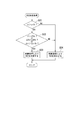
- FIG. 1 is a control block diagram of a turning control device of a vehicle according to a first embodiment.
- a turning control device 1A (1) of a vehicle according to the present embodiment includes a brake control unit 2 and a braking device (braking control device) 10.
- the brake control unit 2 determines the braking force control amount of the front, rear, left and right wheels of the vehicle according to the traveling state of the vehicle.
- the brake device 10 controls the braking force of each wheel based on the braking force control amount of each wheel determined by the brake control unit 2.
- the brake control unit 2 includes a steering angle sensor (steering amount detection device) 3 for detecting a steering angle (steering amount) of a steering wheel of the vehicle, a vehicle speed sensor (vehicle velocity detection device) 4 for detecting a vehicle speed Lateral acceleration sensor (lateral acceleration detection device, hereinafter abbreviated as lateral G sensor) 5 that detects acceleration in the vehicle width direction, that is, lateral acceleration (hereinafter abbreviated as lateral G) 5, yaw rate sensor (yaw rate detection) that detects the yaw rate of the vehicle
- lateral G sensor vehicle speed Lateral acceleration sensor
- lateral G sensor lateral acceleration detection device
- yaw rate sensor yaw rate detection
- a detection signal corresponding to the detection value obtained by each of the sensors is input from the accelerator opening degree sensor (required torque detection device) 7 that detects the accelerator opening degree of the vehicle and the vehicle.
- an electric signal corresponding to the calculated friction coefficient is input to the brake control unit 2 from the ⁇ calculating
- the brake control unit 2 includes a steering angle reference yaw rate calculation unit 11, a steady state reference yaw rate calculation unit 12, a lateral G reference yaw rate calculation unit (control amount calculation unit) 14, a correction unit 15, a limit yaw rate deviation calculation unit 16, and a first braking force. And a control operation unit (feedback control amount operation unit, hereinafter abbreviated to FB control amount operation unit) 19.
- FB control amount operation unit feedback control amount operation unit
- the steering angle reference yaw rate calculation unit 11 calculates a steering angle reference yaw rate based on the steering angle of the steering wheel detected by the steering angle sensor 3 and the vehicle speed of the vehicle detected by the vehicle speed sensor 4.
- the steering angle reference yaw rate increases because the steering angle of the steering wheel is increased. That is, when the steering angle reference yaw rate calculated based on the steering angle is large, it can be estimated that the driver's steering intention to bend the vehicle is large.
- the steady state yaw rate calculating unit 12 calculates a steady state yaw rate gain Kv according to the vehicle speed with reference to the steady state yaw rate gain table 21 and multiplies the steered angle yaw rate by the steady state yaw rate gain Kv to calculate a steady state yaw rate ⁇ _high.
- the horizontal axis is the vehicle speed
- the vertical axis is the steady state yaw rate gain Kv
- the steady state yaw rate gain Kv converges to 1 as the vehicle speed increases, and the steady state yaw rate as the vehicle speed decreases.
- the gain Kv is set to be large.
- the lateral G reference yaw rate calculation unit 14 calculates a lateral G reference yaw rate (first reference yaw rate) ⁇ _low based on the lateral G detected by the lateral G sensor 5 and the vehicle speed detected by the vehicle speed sensor 4.
- Gy is a lateral acceleration detection value detected by the lateral G sensor 5
- V is a vehicle speed detected by the vehicle speed sensor 4.
- the correction unit 15 calculates a limit reference yaw rate (second reference yaw rate) ⁇ _TAR based on the steady-state reference yaw rate ⁇ _high and the lateral G reference yaw rate ⁇ _low. The method of calculating the limit reference yaw rate ⁇ _TAR in the correction unit 15 will be described in detail later.
- the limit yaw rate deviation calculation unit 16 subtracts the yaw rate (actual yaw rate) detected by the yaw rate sensor 6 from the limit reference yaw rate ⁇ _TAR to calculate the limit yaw rate deviation ⁇ fb.
- the FB control amount calculation unit 19 calculates a feedback control amount (a braking force control amount, hereinafter abbreviated as an FB control amount) based on the limit yaw rate deviation ⁇ fb, and outputs it to the brake device 10 as a command value.
- a feedback control amount a braking force control amount, hereinafter abbreviated as an FB control amount
- the correction unit 15 includes a distribution coefficient HB1 calculation unit (first correction restriction unit) 31, a reference limit reference yaw rate calculation unit 32, a correction coefficient HS1 calculation unit (second correction restriction unit) 33, and a correction coefficient
- An HS2 calculation unit (third correction restriction unit) 34 and a correction coefficient HS3 calculation unit (fourth correction restriction unit) 35 are provided.
- the reference limit reference yaw rate ⁇ _t1 is determined based on the distribution coefficient HB1 calculated by the distribution coefficient HB1 calculation unit 31, the steady state reference yaw rate ⁇ _high, and the lateral G reference yaw rate ⁇ _low. It is calculated. Further, the reference limit reference yaw rate ⁇ _t1 is multiplied by the correction coefficient HS1 calculated by the correction coefficient HS1 calculation unit 33 and the correction coefficient HS2 calculated by the correction coefficient HS2 calculation unit 34, and this value is further corrected by the correction coefficient HS3 calculation unit 35.
- the limit reference yaw rate ⁇ _TAR is calculated by adding the calculated correction coefficient HS3 (see the following equation (1)).
- a correction amount to be corrected in the direction of increasing the lateral G reference yaw rate ⁇ _low is determined by the distribution coefficient HB1, the correction coefficient HS1, the correction coefficient HS2, and the correction coefficient HS3.
- ⁇ _TAR ⁇ _t1 ⁇ HS1 ⁇ HS2 + HS3 ⁇ ⁇ ⁇ Formula (1)
- the limit reference yaw rate ⁇ _TAR is a target value of the yaw rate in feedback control.
- the reference limit reference yaw rate calculation unit 32 relates the steady-state reference yaw rate ⁇ _high calculated based on the steering angle to the lateral G reference yaw rate ⁇ _low, which is the target value in the feedback control in the conventional steering assist brake control.
- the reference limit reference yaw rate ⁇ _t1 is calculated by correcting in the increasing direction.
- FIG. 3 shows temporal changes in the steering angle standard yaw rate and the lateral G standard yaw rate until the steering wheel is rotated from the state where the vehicle is going straight and the steering wheel is held at a predetermined steering angle.
- the steering angle reference yaw rate is larger than the lateral G reference yaw rate. Therefore, as a method for increasing and correcting the lateral G reference yaw rate, correction is made to approach the steering angle reference yaw rate, and how close the steering angle reference yaw rate is to be adjusted is adjusted according to the traveling state.
- the adjustment method the concept of the distribution coefficient of the lateral G reference yaw rate and the steering angle reference yaw rate was adopted.
- the lateral G reference yaw rate is corrected so as to be close to the steady reference yaw rate ⁇ _high calculated based on the steering angle reference yaw rate.
- the reference limit reference from the following equation (2) The yaw rate ⁇ _t1 is calculated.
- ⁇ _t1 HB1 ⁇ ⁇ _high + (1-HB1) ⁇ ⁇ _low ⁇
- the distribution coefficient HB1 is a numerical value of 0 to 1.
- HB1 0, the reference limit reference yaw rate ⁇ _t1 is the lateral G reference yaw rate ⁇ _low.
- HB1 1, the reference limit reference yaw rate ⁇ _t1 becomes the steady-state reference yaw rate ⁇ _high.
- the distribution coefficient HB1 is calculated according to the vehicle speed, the distribution coefficient HB1b calculated according to the yaw rate change rate, the distribution coefficient HB1c calculated according to the yaw rate deviation integral, and the steering speed It is calculated by multiplying the distribution coefficient HB1d calculated as above (refer to the following equation (3)).
- HB1 HB1a ⁇ HB1b ⁇ HB1c ⁇ HB1d ⁇ ⁇ ⁇ Formula (3)
- the respective distribution coefficients HB1a, HB1b, HB1c, and HB1d are calculated with reference to distribution coefficient tables 40, 41, 42, and 43 shown in FIG. Below, each distribution coefficient table 40, 41, 42, 43 in this embodiment is demonstrated.
- the horizontal axis is the vehicle speed
- the vertical axis is the distribution coefficient HB1a.
- the limit reference yaw rate ⁇ _TAR as the target value is increased in the FB control amount calculation unit 19, and the turning performance and the followability of the vehicle can be improved.
- the stability of the vehicle behavior can be ensured by not increasing the limit reference yaw rate ⁇ _TAR that is the target value in the FB control amount calculation unit 19.
- the horizontal axis is the yaw rate change rate
- the vertical axis is the distribution coefficient HB1b.
- the yaw rate change rate is a temporal change of the actual yaw rate detected by the yaw rate sensor 6, and can be calculated by time-differentiating the actual yaw rate.
- a large yaw rate change rate appears when the vehicle is in a slalom running or when the vehicle behavior is unstable.
- the limit reference yaw rate ⁇ _TAR as the target value should not be increased in the FB control amount calculation unit 19, so when the change rate of the yaw rate is large, the distribution coefficient HB1b is set to a small value and the limit reference yaw rate ⁇ _TAR is not increased. Let's do it.
- the horizontal axis is the yaw rate deviation integral value
- the vertical axis is the distribution coefficient HB1c.
- the yaw rate deviation integral value is a value obtained by integrating the deviation between the limit reference yaw rate and the actual yaw rate detected by the yaw rate sensor 6, that is, the limit yaw rate deviation ⁇ fb from when steering of the steering wheel is started. For example, if the state continues for a long time even if the limit yaw rate deviation ⁇ fb is small, the yaw rate deviation integral value becomes large. In such a case, there is a possibility that the vehicle is in a spin state gradually but slowly, so the limit reference yaw rate ⁇ _TAR that is the target value in the FB control amount calculation unit 19 should not be increased. Therefore, when the yaw rate deviation integral value is large, the distribution coefficient HB1c is set to a small value so that the limit reference yaw rate ⁇ _TAR is not increased.
- the horizontal axis is the turning speed
- the vertical axis is the distribution coefficient HB1d.
- the distribution coefficient table 43 is set so that the distribution coefficient HB1d increases as the turning speed increases, and the distribution coefficient HB1d increases when the turning speed is positive than when the turning speed is negative.
- the turning speed is a value determined based on the time change amount of the steering angle of the steering wheel detected by the steering angle sensor 3 and the steering angle, and the steering angle is differentiated with respect to time and compared with the steering angle. calculate.
- the distribution coefficient HB1d may be calculated based on the turning angle (turning amount) instead of the turning speed. This is because it can be estimated that the larger the turning angle, the larger the driver's intention to bend the vehicle positively.
- the turning angle in this case is synonymous with the steering angle.
- the correction coefficient HS1 is a correction coefficient on the assumption that the driver performs an operation of bending the vehicle by turning the steering wheel with the vehicle at the front load. As shown in FIG. 5, the correction coefficient HS1 is calculated by multiplying the correction coefficient HS1a calculated according to the steering speed and the correction coefficient HS1b calculated according to the front load of the vehicle (the following equation See 4).
- the front load of the vehicle is the amount of load movement to the front of the vehicle, and can be estimated, for example, based on a longitudinal acceleration sensor (not shown) that detects acceleration in the longitudinal direction of the vehicle.
- the longitudinal acceleration sensor can be said to be a load movement amount estimation device that estimates the load movement amount in the front and rear direction.
- the correction coefficients HS1a and HS1b are calculated with reference to the correction coefficient tables 44 and 45 shown in FIG. 5, respectively.
- the correction coefficient tables 44 and 45 in the present embodiment will be described.
- the horizontal axis is the steering speed
- the vertical axis is the correction coefficient HS1a.
- the horizontal axis is a front load (load moving amount to the front of the vehicle), and the vertical axis is a correction coefficient HS1b.
- the correction coefficient HS1 is a correction coefficient for adjusting the limit reference yaw rate ⁇ _TAR at the time of such steering.
- the correction coefficient HS1 becomes 1 in the region where the steering speed is small and the front load is small, the limit reference yaw rate ⁇ _TAR can be increased, and the turning of the vehicle is improved. It can improve.
- the correction coefficient HS1 becomes smaller than 1 as the steering speed and the front load increase, so that the limit reference yaw rate ⁇ _TAR can be reduced, and the stability of the vehicle behavior can be ensured.
- This correction coefficient HS2 is used for a lane change (steering is performed immediately on the road surface where the coefficient of friction between the wheel and the road surface (hereinafter referred to as ⁇ ) is high). It is a correction coefficient on the assumption that the operation of returning to the direction is performed.
- the correction coefficient HS2 takes a maximum value of 1 and subtracts a predetermined decrease count value from the initial value when the following conditions are satisfied, and a predetermined increase count value toward 1 when any of the following conditions is not satisfied.
- Is a gain configured to add As conditions, (a) when it is judged that the coefficient of friction ⁇ is high (or when longitudinal acceleration or lateral acceleration corresponding to traveling on a road surface with a high coefficient of friction is detected), (b) it is judged that the steering angle is large. When it is determined that (c) the lateral G decrease rate is determined to be large, and (d) the yaw rate decrease rate is determined to be large, a predetermined decrease count value is subtracted.
- the above condition may be any combination of at least one or more of (a) to (d). In particular, in consideration of the convergence of the vehicle behavior at the time of high coefficient of friction, it is preferable to use any one of the above (a) and (b) to (d) in combination.
- the coefficient of friction ⁇ is calculated by the ⁇ calculator 8.
- the lateral G decrease rate is the lateral G decrease rate, and is calculated based on the lateral G detected by the lateral G sensor 5.
- the yaw rate reduction rate is the reduction rate of the actual yaw rate detected by the yaw rate sensor 6.
- step S01 it is determined whether the coefficient of friction ⁇ is larger than a threshold ⁇ th. If the determination result in step S01 is "YES"(.mu.>. Mu.th), the process proceeds to step S02 to determine whether the steering angle .delta. Is larger than the threshold .delta.th (.delta.>. Delta.th) or the lateral G reduction rate .DELTA.G is a threshold It is determined whether there is any one that is larger than ⁇ Gth ( ⁇ G> ⁇ Gth) or that the yaw rate reduction rate ⁇ is larger than the threshold ⁇ th ( ⁇ > ⁇ th).
- step S03 the correction coefficient HS2 is determined by subtraction processing, and the execution of this routine is temporarily ended.
- a predetermined subtraction count value is subtracted from the initial value of the correction coefficient HS2 so that the correction coefficient HS2 converges to zero.
- step S04 the correction coefficient HS2 is determined by the addition process. And temporarily end the execution of this routine.
- a predetermined increase count value is added so that the correction coefficient HS2 converges to one.
- the initial value of the correction coefficient HS2 is a predetermined value between 0 and 1.
- the correction coefficient HS2 is for suppressing this. That is, when the coefficient of friction ⁇ , the steering angle, the lateral G decrease rate, and the yaw rate decrease rate are large, the limit reference yaw rate ⁇ _TAR is not increased by setting the correction coefficient HS2 to a small value, and after the lane change Improve the yaw rate convergence.
- the correction coefficient HS3 is a correction coefficient on the assumption that the driver tacks in.
- Tack-in is a phenomenon where when the accelerator pedal is suddenly released while turning, the vehicle becomes a front load and enters the inside of the turning direction, but some drivers use this to make a positive turn operation There is.
- the turning operation using this tack-in makes the vehicle behavior unstable when releasing the accelerator from when the required torque to the vehicle is large (in other words, when the accelerator opening is large) or when the vehicle speed is large. easy.
- the required torque of the vehicle can be calculated from the accelerator opening detected by the accelerator opening sensor 7, and the required torque becomes larger as the accelerator opening becomes larger.
- the correction coefficients HS3a and HS3b are calculated with reference to correction coefficient tables 51 and 52 shown in FIG. 7, respectively.
- the correction coefficient tables 51 and 52 in the present embodiment will be described.
- the horizontal axis is the vehicle speed
- the vertical axis is the correction coefficient HS3a.
- HS3a is a positive constant value in a region where the vehicle speed is smaller than a predetermined value
- the correction coefficient HS3a gradually decreases as the vehicle speed increases when the vehicle speed becomes equal to or higher than the predetermined value.
- it exceeds the predetermined speed V0 it becomes a negative value, and in a region where the vehicle speed is very high, HS3a becomes a negative constant value.
- the horizontal axis is the required torque of the vehicle
- the vertical axis is the correction coefficient HS3b.
- HS3b is a positive value in a region where the required torque is smaller than a predetermined value T0
- the correction coefficient HS3b 0 in a region where the required torque is a predetermined value T0 or more.
- the predetermined value T0 is an extremely small value, and for example, it is set to the required torque corresponding to the time when the accelerator opening is close to zero.
- correction coefficient HS3 is obtained regardless of the magnitude of the vehicle speed when the required torque is equal to or greater than predetermined value T0 (that is, when it is determined not to be in the tack-in state). Becomes 0, and it is possible not to correct the limit reference yaw rate ⁇ _TAR. Further, when the required torque is less than or equal to the predetermined value T0 (ie, when it is determined that the vehicle is in the tack-in state) and the vehicle speed is smaller than V0, the correction coefficient HS3 takes a positive value. The yaw rate ⁇ _TAR can be increased.
- the correction coefficient HS3 has a negative value, so that the limit reference yaw rate ⁇ _TAR can be reduced. Furthermore, when the vehicle speed is smaller than V0 and the required torque is the same, the limit reference yaw rate ⁇ _TAR can be increased by setting the correction coefficient H3 to a larger positive value as the vehicle speed decreases. As a result, it is possible to improve the turning performance of the vehicle when tacking in at a low or medium speed. In particular, the turning performance of the vehicle at the time of tack-in improves as the vehicle speed decreases.
- the limit reference yaw rate ⁇ _TAR can be reduced by setting the correction coefficient H3 to a large negative value as the vehicle speed increases.
- the FB control amount calculation unit 19 based on the limit yaw rate deviation ⁇ fb calculated by the limit yaw rate deviation calculation unit 16, the FB pressure increase amount ⁇ P 1 fb of the FR inner ring, the front wheel side outer ring (hereinafter abbreviated as the FR outer ring)
- the FB pressure increase amount ⁇ P3fb of the second embodiment, the FB pressure increase amount ⁇ P2fb of the RR inner ring, and the FB pressure increase amount ⁇ P4fb of the rear wheel-side turning outer ring (hereinafter, abbreviated as RR turning outer ring) are calculated.
- ⁇ P1 fb, ⁇ P3 fb, ⁇ P2 fb, and ⁇ P4 fb are the first braking force control amount.
- the sign of the deviation ⁇ fb is positive and the reference yaw rate and the actual yaw rate are both positive will be described as an example.
- the FB pressure increase amount ⁇ P1 fb of the FR turning inner ring is calculated with reference to the pressure increase amount table 80 based on the limit yaw rate deviation ⁇ fb.
- the horizontal axis is the limit yaw rate deviation ⁇ fb
- the vertical axis is the FB pressure increase amount ⁇ P1fb.
- the FB pressure increase amount ⁇ P1 fb is 0 when the limit yaw rate deviation ⁇ fb is 0 or less
- ⁇ P1 fb increases.
- the FB pressure increase amount ⁇ P2 fb of the RR turning inner ring is calculated with reference to the pressure increase amount table 81 based on the limit yaw rate deviation ⁇ fb.
- the horizontal axis is the limit yaw rate deviation ⁇ fb
- the vertical axis is the FB pressure increase amount ⁇ P2fb.
- the FB pressure increase amount ⁇ P2fb is 0 when the limit yaw rate deviation ⁇ fb is 0 or less
- the FB pressure increase amount ⁇ P2fb increases as the limit yaw rate deviation ⁇ fb increases when the limit yaw rate deviation ⁇ fb is 0 or more. I will.
- the FB pressure increase amount ⁇ P3fb of the FR turning outer ring is calculated with reference to the pressure increase amount table 82 based on the limit yaw rate deviation ⁇ fb.
- the horizontal axis is the limit yaw rate deviation ⁇ fb
- the vertical axis is the FB pressure increase amount ⁇ P3fb.
- the FB pressure increase amount ⁇ P3fb is 0, and when the limit yaw rate deviation ⁇ fb is 0 or less, the FB increases as the absolute value of the limit yaw rate deviation ⁇ fb increases.
- the pressure increase amount ⁇ P3fb increases.
- the FB pressure increase amount ⁇ P4fb of the RR turning outer ring is calculated with reference to the pressure increase amount table 83 based on the limit yaw rate deviation ⁇ fb.
- the horizontal axis is the limit yaw rate deviation ⁇ fb
- the vertical axis is the FB pressure increase amount ⁇ P4fb.
- the FB pressure increase amount ⁇ P4fb is 0, and when the limit yaw rate deviation ⁇ fb is 0 or less, the FB increases as the absolute value of the limit yaw rate deviation ⁇ fb increases.
- the pressure increase amount ⁇ P4fb increases.
- the FB control amount calculation unit 19 when the limit yaw rate deviation ⁇ fb is 0 or more, the actual yaw rate is smaller than the limit standard yaw rate, so the direction to increase the yaw rate (in other words, the direction to cancel the limit yaw rate deviation ⁇ fb)
- the FB pressure increase amount is set in the direction to increase the brake fluid pressure of the FR turning inner ring and the RR turning inner ring
- the FB pressure increasing amount is set so as not to increase the brake fluid pressure of the FR turning outer ring and the RR turning outer ring.
- the FB control amount of each wheel in the direction to reduce the yaw rate (in other words, the direction to cancel the limit yaw rate deviation ⁇ fb)
- the FB pressure increase amount is set in the direction to increase the brake fluid pressure of the FR turning outer ring and the RR turning outer ring
- the FB pressure increasing amount is set so as not to increase the brake hydraulic pressure of the FR turning inner ring and the RR turning inner ring.
- the FB control amount calculation unit 19 calculates the FB pressure increase amount ⁇ P1fb of the FR inner wheel, the FB pressure increase amount ⁇ P2fb of the RR inner ring, the FB pressure increase amount ⁇ P3fb of the FR outer ring, and the FB pressure increase of the RR outer ring.
- the amount ⁇ P4 fb is output to the brake device 10.
- the brake device 10 controls the brake pressure of each wheel in accordance with the input control amount of each wheel.
- the lateral G reference yaw rate ⁇ _low is corrected in the increasing direction in association with the steady reference yaw rate ⁇ _high calculated based on the steering angle by the correction unit 15 and the limit reference Since the yaw rate ⁇ _TAR is calculated, it is possible to achieve both the control for stabilizing the yaw moment generated in the vehicle body and the control for improving the response of steering. As a result, the driver's turning intention is responsively reflected, and the steering feel is improved.
- the target value in the FB control amount calculation unit 19 can be increased, and the turning of the vehicle is improved. As a result, it becomes possible to turn the vehicle along the runway, and the road surface tracking performance (traceability) is improved.
- the correction unit 15 includes the distribution coefficient HB1 calculation unit 31, the correction coefficient HS1 calculation unit 33, the correction coefficient HS2 calculation unit 34, and the correction coefficient HS3 calculation unit 35, the vehicle condition and the road surface condition (for example, high ⁇ The convergence of the yaw rate is improved according to the lane change on the road, etc., and the traceability of the vehicle for steering is improved even if the vehicle is at a low speed.
- FIG. 9 is a control block diagram of the turning control device 1B (1) of the vehicle according to the second embodiment.
- the control amount (FB control amount) is determined in the direction in which the deviation between the limit reference yaw rate ⁇ _TAR and the actual yaw rate (ie, the limit yaw rate deviation ⁇ fb) is canceled.
- the brake pressure is controlled by the amount only.
- a feedforward control amount (hereinafter abbreviated as an FF control amount) is calculated based on the steering angle and the vehicle speed, and the FB control amount and the FF control amount are added.
- the value obtained by the above is taken as the total control amount, and the brake pressure of each wheel is controlled based on this total control amount.
- a feedback control system that is, a steering angle reference yaw rate calculating unit 11, a steady reference yaw rate calculating unit 12, a lateral G reference yaw rate
- the calculation unit 14, the correction unit 15, the limit yaw rate deviation calculation unit 16, and the FB control amount calculation unit 19 are the same as in the first embodiment, so the same reference numerals are given to the same aspect parts and the description is omitted.
- differences from the first embodiment will be described focusing on a feedforward control system.
- the turning control device 1B (1) of the vehicle according to the second embodiment has, as a feedforward control system, a steady-state yaw rate deviation calculating unit 13 and a feedforward control
- An amount calculation unit (a second braking force control calculation unit, hereinafter, referred to as an FF control amount calculation unit) 18 is provided.
- a braking force control amount computing unit 17 is configured by the FF control amount computing unit 18 and the FB control amount computing unit 19 in the first embodiment.
- the steady-state yaw rate deviation calculation unit 13 performs the time change amount smoothing process or the peak hold process on the steering angle reference yaw rate calculated by the steering angle reference yaw rate calculation unit 11 to remove noise, thereby eliminating the noise. It is input. Then, the steady-state yaw rate deviation calculation unit 13 subtracts the steering angle standard yaw rate after noise removal from the steady-state standard yaw rate ⁇ _high to calculate the steady-state yaw rate deviation ⁇ ff.
- the braking force control amount calculation unit 17 calculates the feedforward control amount based on the steady state yaw rate deviation ⁇ ff in the FF control amount calculation unit 18, and the feedback control amount (FB based on the limit yaw rate deviation ⁇ fb in the FB control amount calculation unit 19.
- the control amount is calculated, and further, the FF control amount and the FB control amount are added to calculate the total control amount, which is output to the brake device 10 as the command value.
- the brake control amount calculation performed in the braking force control amount calculation unit 17 will be described.
- the calculation of the FF control amount in the FF control amount calculation unit 18 will be described.
- FR turning inner wheel the pressure increase distribution to the turning inner wheel on the front wheel side
- RR turning inner ring the turning inner wheel on the rear wheel side
- the pressure increase coefficient K1fr for the FR inner wheel in the turning and the pressure increasing coefficient K1rr for the inner wheel in the RR turning are calculated.
- the pressure increase coefficient K1fr for the FR turning inner wheel may be set to be large according to the steering angle.
- the calculation of the FF pressure increase amount ⁇ P1ff for the FR inner race in parallel with the calculation of the FF pressure increase amount ⁇ P2ff for the RR inner race in parallel based on the pressure increase coefficient K1fr for the FR inner race and the pressure increase coefficient K1rr for the RR inner race To be implemented. Note that these ⁇ P1ff and ⁇ P2ff are second braking force control amounts.
- the steady state yaw rate deviation ⁇ ff calculated by the steady state yaw rate deviation calculation unit 13 is multiplied by the increase coefficient K1fr to calculate the steady state yaw rate deviation ⁇ 1ff with respect to the FR turning inner wheel.
- the brake fluid pressure increase amount ⁇ P1ffk of the FR turning inner wheel is calculated according to the steady-state yaw rate deviation ⁇ 1ff with respect to the FR turning inner wheel.
- the horizontal axis is the steady state yaw rate deviation ⁇ 1ff
- the vertical axis is the brake fluid pressure increase amount ⁇ P1ffk.
- the brake fluid pressure pressure increase amount ⁇ P1ffk is 0 when the steady state yaw rate deviation ⁇ 1ff with respect to the FR turning inner wheel is 0 or less, and the steady state yaw rate deviation ⁇ 1ff is large when the steady state yaw rate deviation ⁇ 1ff with respect to the FR turning inner ring is 0 or more
- the brake fluid pressure increase amount ⁇ P1ffk increases as it becomes.
- the upper limit value is an arbitrary value calculated by the first upper limit value calculation unit 62. By setting the upper limit value not to exceed this value, a sudden change of the hydraulic pressure increase amount ⁇ Plffk is suppressed.
- the FF hydraulic pressure increase amount ⁇ P1ff for the FR turning inner wheel is calculated by multiplying the brake hydraulic pressure pressure increasing amount ⁇ P1ffk of the FR turning inner ring subjected to the limit processing by a gain according to the vehicle speed.
- the gain according to the vehicle speed is calculated based on the first gain table 63.
- the horizontal axis is the vehicle speed
- the gain table 63 constitutes an invalidation mechanism.
- an arbitrary limit value may be given such that the value decreases as the vehicle speed increases, and the limit value may be set so that ⁇ Plff does not exceed.
- the calculation of the FF pressure increase amount ⁇ P2ff with respect to the RR turning inner ring is the same as the calculation of the FF pressure increasing amount ⁇ Pfr1 with respect to the FR turning inner wheel, and therefore will be briefly described.
- the steady state yaw rate deviation ⁇ ff calculated by the steady state yaw rate deviation calculation unit 13 is multiplied by the increase coefficient K 1 rr for the RR inner wheel to calculate the steady state yaw rate deviation ⁇ 2 ff for the RR inner wheel.
- the brake fluid pressure increase amount ⁇ P2ffk of the RR inner wheel is calculated according to the steady-state yaw rate deviation ⁇ 2ff with respect to the RR inner wheel.
- the second pressure increase amount table 64 is the same as the first pressure increase amount table 60, the description will be omitted.
- limit processing is performed so that the brake hydraulic pressure increase amount ⁇ P2ffk of the inner wheel in the RR corner does not exceed the upper limit value.
- the upper limit value is calculated by the second upper limit value calculation unit 66.
- the second upper limit value calculation unit 66 is the same as the first upper limit value calculation unit 62.
- the FF hydraulic pressure increase amount ⁇ P2ff for the RR inner race is calculated by multiplying the brake hydraulic pressure increase amount ⁇ P2ffk for the RR inner race which has been subjected to the limit processing by the gain calculated by the second gain table 67.
- the second gain table 67 is the same as the first gain table 63, so the description thereof is omitted.
- the second gain table 67 constitutes an invalidation mechanism.
- the FF control amount calculation unit 18 includes an inner ring pressure reduction amount calculation unit 70.
- the inner wheel pressure reduction amount calculation unit 70 is for limiting in advance the brake fluid pressure of the turning inner wheel under the premise that the vehicle behavior becomes unstable due to braking at high speed or high side G.
- the inner ring pressure reduction amount calculation unit 70 calculates the pressure reduction rate according to the vehicle speed with reference to the first pressure reduction rate table 71, and calculates the pressure reduction rate according to the lateral G with reference to the second pressure reduction rate table 72, The total pressure reduction rate is calculated by multiplying these pressure reduction rates.
- the horizontal axis is the vehicle speed
- the vertical axis is the pressure reduction rate
- the pressure reduction rate becomes constant at 0 when the vehicle speed is small.
- the pressure reduction rate gradually increases, and the pressure reduction rate becomes constant at 1 in a region where the vehicle speed is large.
- the horizontal axis is horizontal G
- the vertical axis is a pressure reduction rate
- the pressure reduction rate becomes constant at 0, and when the horizontal G becomes a predetermined value or more, the horizontal G is As the pressure increases, the pressure reduction rate gradually increases.
- the total pressure reduction rate is set to a value between 0 and 1 according to the vehicle speed and the lateral G at the time of traveling. Then, the total pressure reduction rate thus obtained is multiplied by the master cylinder pressure of the brake device 10, and further multiplied by minus 1 to obtain the inner ring pressure reduction amount ⁇ Pd.
- the calculation of the FB control amount in the FB control amount calculation unit 19 is the same as in the first embodiment, and thus the description thereof is omitted.
- the braking force control amount calculation unit 17 sets a value obtained by adding the FF pressure increase amount ⁇ P1ff of the FR inner wheel to the FB pressure increase amount ⁇ P1fb of the FR inner wheel to the inner wheel pressure reduction amount ⁇ Pd as a total control amount for the FR inner wheel.
- a value obtained by adding the FF pressure increase amount ⁇ P2ff of the RR inner ring, the FB pressure increase amount ⁇ P2fb of the RR inner ring, and the inner wheel pressure reduction amount ⁇ Pd is the total control amount for the RR inner ring
- the FB pressure increase amount ⁇ P3fb of the FR outer ring is FR
- the FB pressure increase amount ⁇ P4 fb of the RR turning outer ring is output to the brake device 10 as the total control amount of the RR turning outer ring.
- the brake device 10 controls the brake pressure of each wheel in accordance with the input control amount of each wheel.
- the lateral G reference yaw rate ⁇ _low is related to the steady reference yaw rate ⁇ _high calculated by the correction unit 15 based on the steering angle, as in the first embodiment.
- the value is corrected in the increasing direction, and the limit reference yaw rate ⁇ _TAR is calculated. Therefore, it is possible to achieve both the control for stabilizing the yaw moment generated in the vehicle body and the control for improving the response of steering. As a result, the driver's turning intention is responsively reflected on the behavior of the vehicle, and the steering feel is improved.
- the target value in the FB control amount calculation unit 19 can be increased, and the turning of the vehicle is improved. As a result, it becomes possible to turn the vehicle along the runway, and the road surface tracking performance (traceability) is improved.
- the correction unit 15 includes the distribution coefficient HB1 calculation unit 31, the correction coefficient HS1 calculation unit 33, the correction coefficient HS2 calculation unit 34, and the correction coefficient HS3 calculation unit 35, the vehicle condition and the road surface condition (for example, high The convergence of the yaw rate is improved according to the lane change on the ⁇ road, etc., and the traceability of the vehicle for steering is improved even if the vehicle is at a low speed.
- the brake pressure is controlled based on the total control amount obtained by adding the FF control amount calculated based on the steering input to the FB control amount calculated based on the vehicle behavior. Accordingly, it is possible to improve the response and followability of steering while securing the stability of the vehicle behavior. For example, in the process of steering and holding after steering input, such as at the time of steady circular turning, the fluctuation of the control amount is suppressed, and the road surface following property of the vehicle is improved.
- the present embodiment is different from the above-described first embodiment in that in the first embodiment, whether or not it is in the tack-in state is determined based on the required torque, while in the third embodiment, the accelerator pedal or accelerator is Whether or not it is in the tack-in state based on the return speed of the opening (hereinafter referred to as return speed), or whether or not it is in the tack-in state based on both the required torque and the return speed It is a point. That is, this determination method of the present embodiment can be applied to the second embodiment in addition to the first embodiment. Hereinafter, these determination methods will be described in detail.
- the correction coefficient HS3c is calculated with reference to the correction coefficient table 53 shown in FIG. In the correction coefficient table 53, the horizontal axis is the return speed, and the vertical axis is the correction coefficient HS3c.
- the correction coefficient HS3c table 53 the correction coefficient HS3c becomes constant in a region where the return speed is less than a predetermined value, and when the return speed exceeds the predetermined value, the correction coefficient HS3c gradually increases as the return speed increases. And converge to the maximum value A and become constant.
- the predetermined value is set to a return speed that is a determination threshold value for determining whether the operation is a tuck-in operation. In this way, it is determined that the vehicle is not in the tack-in state when the speed for returning the accelerator pedal or the accelerator opening is slower than the predetermined value, and the correction coefficient HS3c is set to 0 to correct the limit reference yaw rate ⁇ _TAR by the correction coefficient HS3.
- the correction coefficient HS3 can be calculated, and the same effect as that of the first embodiment or the second embodiment can be obtained.
- FIG. 13 is a control block diagram of the turning control device for a vehicle according to the fourth embodiment.
- a turning control device 1C (1) of a vehicle according to the present embodiment includes a brake control unit 2 and a braking device (braking control device) 10.
- the brake control unit 2 determines the braking force control amount of the front and rear left and right wheels according to the traveling state of the vehicle.
- the brake device 10 controls the braking force of each wheel based on the braking force control amount of each wheel determined by the brake control unit 2.
- the brake control unit 2 includes a steering angle sensor (steering amount detection device) 3 for detecting a steering angle (steering amount) of a steering wheel of the vehicle, a vehicle speed sensor (vehicle velocity detection device) 4 for detecting a vehicle speed
- the yaw rate sensor 6 that detects the yaw rate of the vehicle A detection signal corresponding to the obtained detection value is input.
- the brake control unit 2 includes an assist amount calculation unit (assist amount setting device) 23, a lateral G reference yaw rate calculation unit 14, a yaw rate deviation calculation unit 16, and a braking force control amount calculation unit 17.
- the braking force control amount computing unit 17 includes a second braking force control computing unit (a feedforward control amount computing unit, hereinafter referred to as an FF control amount computing unit) 18 and a first braking force control computing unit (feedback control amount computing unit , And hereinafter, referred to as an FB control amount calculation unit) 19).
- the horizontal axis is the steering angle
- the vertical axis is the steering angle gain Ks
- the negative steering angle is the steering angle when the steering wheel is turned counterclockwise from the neutral position.
- the steering angle gain Ks when the absolute value of the steering angle is less than a predetermined value, the steering angle gain Ks becomes constant at 0, and when the absolute value of the steering angle reaches the predetermined value, the steering angle gain Ks is positive.
- the steering angle gain Ks is set to gradually increase as the absolute value of the steering angle increases when the value suddenly increases to a fixed value and exceeds the predetermined value.
- the horizontal axis is the vehicle speed
- the vertical axis is the vehicle speed gain Kv
- the vehicle speed gain Kv decreases and converges to 1 as the vehicle speed increases
- the vehicle speed gain Kv decreases as the vehicle speed decreases. It is set to be large. Since the steering angle gain table 24 and the vehicle speed gain table 25 are set as described above, the assist amount As is 0 regardless of the vehicle speed when the absolute value of the steering angle is less than a predetermined value. On the other hand, when the absolute value of the steering angle becomes a predetermined value or more, the assist amount As increases as the absolute value of the steering angle increases, and the assist amount As increases as the vehicle speed decreases and decreases as the vehicle speed increases. .
- the lateral G reference yaw rate calculation unit 14 calculates a lateral G reference yaw rate ⁇ _low based on the lateral G detected by the lateral G sensor 5 and the vehicle speed detected by the vehicle speed sensor 4.
- Gy is a lateral acceleration detection value detected by the lateral G sensor 5
- V is a vehicle speed detected by the vehicle speed sensor 4.
- the yaw rate deviation calculation unit 16 subtracts the yaw rate (actual yaw rate) detected by the yaw rate sensor 6 from the lateral G reference yaw rate ⁇ _low to calculate a yaw rate deviation ⁇ fb.
- the braking force control amount calculation unit 17 calculates the feedforward control amount (hereinafter abbreviated as FF control amount) in the FF control amount calculation unit 18 based on the assist amount As, and makes the yaw rate deviation ⁇ fb in the FB control amount calculation unit 19. Based on the feedback control amount (abbreviated as FB control amount), the FF control amount and the FB control amount are added to calculate the total control amount for each wheel. Then, this added value is output to the brake device 10 as a command value.
- the braking force control amount computing unit 17 constitutes a braking force control amount computing unit.
- the brake control amount calculation performed in the braking force control amount calculation unit 17 will be described.
- calculation of the FF control amount in the FF control amount calculation unit 18 will be described.
- FR inner wheel inner wheel on the front wheel side of the vehicle
- RR inner wheel inner wheel on the rear wheel side
- the pressure increase coefficient K1fr for the FR turning inner wheel may be set to be large according to the steering angle. Then, based on the pressure increase coefficient K1fr for the FR inner race and the pressure increase coefficient K1rr for the RR inner race, calculation of the FF pressure increase ⁇ P1ff for the FR inner race and calculation of the FF pressure increase ⁇ P2ff for the RR inner race are , Will be implemented in parallel.
- the assist amount As calculated by the assist amount calculation unit 23 is multiplied by the increase coefficient K1fr to calculate the assist amount As1 for the FR turning inner wheel.
- the brake hydraulic pressure increase amount ⁇ P1ffk of the FR turning inner wheel is calculated according to the assist amount As1 for the FR turning inner wheel.
- the horizontal axis is the assist amount As1
- the vertical axis is the brake fluid pressure increase amount ⁇ P1ffk.
- the brake hydraulic pressure increase amount ⁇ P1ffk is zero when the assist amount As1 for the FR turning inner wheel is equal to or less than zero.
- the brake hydraulic pressure pressure increase amount ⁇ P1ffk increases as the assist amount As1 increases.
- the upper limit value is an arbitrary value calculated by the first upper limit value calculation unit 62. By setting the upper limit value not to exceed this value, a sudden change of the hydraulic pressure increase amount ⁇ Plffk is suppressed.
- the FF hydraulic pressure increase amount ⁇ P1ff for the FR turning inner wheel is calculated by multiplying the brake hydraulic pressure pressure increasing amount ⁇ P1ffk of the FR turning inner ring subjected to the limit processing by a gain according to the vehicle speed.
- the gain according to the vehicle speed is calculated based on the first gain table 63.
- the horizontal axis represents the vehicle speed
- the vertical axis represents the gain. In a region where the vehicle speed is small, the gain is constant at 1.
- the gain when the vehicle speed becomes a predetermined value or more, the gain gradually decreases as the vehicle speed increases, and in a region where the vehicle speed is large, the gain becomes constant at 0.
- the first gain table 63 constitutes an invalidation mechanism.
- an arbitrary limit value may be given such that the value decreases as the vehicle speed increases, and the limit value may be set so that ⁇ Plff does not exceed.
- the calculation of the FF pressure increase amount ⁇ P2ff with respect to the RR turning inner ring is the same as the calculation of the FF pressure increasing amount ⁇ Pfr1 with respect to the FR turning inner wheel, and therefore will be briefly described.
- An assist amount As2 for the RR inner wheel is calculated by multiplying the assist amount As calculated by the assist amount calculator 23 by the increase coefficient K1 rr for the RR inner wheel.
- the brake hydraulic pressure increase amount ⁇ P2ffk of the RR inner wheel is calculated according to the assist amount As2 for the RR inner wheel.
- the second pressure increase amount table 69 is the same as the first pressure increase amount table 68, so the description will be omitted.
- the second limit processing unit 65 limit processing is performed so that the brake hydraulic pressure increase amount ⁇ P2ffk of the inner wheel in the RR corner does not exceed the upper limit value.
- the upper limit value is calculated by the second upper limit value calculation unit 66.
- the second upper limit value calculation unit 66 is the same as the first upper limit value calculation unit 62.
- the FF hydraulic pressure increase amount ⁇ P2ff for the RR inner race is calculated by multiplying the brake hydraulic pressure increase amount ⁇ P2ffk for the RR inner race which has been subjected to the limit processing by the gain calculated by the second gain table 67.
- the second gain table 67 is the same as the first gain table 63, so the description will be omitted. In the present embodiment, the second gain table 67 constitutes an invalidation mechanism.
- the FF control amount calculation unit 18 includes an inner ring pressure reduction amount calculation unit 70.
- the inner wheel pressure reduction amount calculation unit 70 previously limits the brake fluid pressure of the turning inner wheel under the premise that the vehicle behavior becomes unstable due to the braking when the vehicle is traveling at high speed or when the high side G is applied to the vehicle. belongs to.
- the inner ring pressure reduction amount calculation unit 70 calculates the pressure reduction rate according to the vehicle speed with reference to the first pressure reduction rate table 71, and calculates the pressure reduction rate according to the lateral G with reference to the second pressure reduction rate table 72, The total pressure reduction rate is calculated by multiplying these pressure reduction rates.
- the horizontal axis is the vehicle speed
- the vertical axis is the pressure reduction rate
- the pressure reduction rate becomes constant at 0 when the vehicle speed is small.
- the pressure reduction rate gradually increases, and the pressure reduction rate becomes constant at 1 in a region where the vehicle speed is large.
- the horizontal axis is horizontal G
- the vertical axis is a pressure reduction rate
- the pressure reduction rate becomes constant at 0, and when the horizontal G becomes a predetermined value or more, the horizontal G is As the pressure increases, the pressure reduction rate gradually increases. In a region where the lateral G is large, the pressure reduction rate becomes constant at 1.
- the total pressure reduction rate is set to a value between 0 and 1 according to the vehicle speed and the lateral G at the time of traveling. Then, the total pressure reduction rate set in this way is multiplied by the master cylinder pressure of the brake device 10, and further multiplied by minus 1 to obtain the inner ring pressure reduction amount ⁇ Pd.
- the FB control amount calculation unit 19 calculates the FB control amount ⁇ P1fb of the inner wheel in the FR turning and the FB in the turning outer ring on the front wheel side (hereinafter, abbreviated as FR turning outer ring) based on the yaw rate deviation ⁇ fb calculated by the yaw rate deviation calculating unit 16.
- the pressure increase amount ⁇ P3 fb, the FB pressure increase amount ⁇ P2 fb of the RR inner ring, and the FB pressure increase amount ⁇ P4 fb of the rear wheel-side turning outer ring (hereinafter, abbreviated as RR turning outer ring) are calculated.
- the following description will be made by way of example in which the sign of the deviation ⁇ fb is positive and both the standard yaw rate and the actual yaw rate are positive.
- the FB pressure increase amount ⁇ P1 fb of the FR turning inner ring is calculated with reference to the first pressure increase amount table 80 based on the yaw rate deviation ⁇ fb.
- the horizontal axis is the yaw rate deviation ⁇ fb
- the vertical axis is the FB pressure increase amount ⁇ P1fb.
- the FB pressure increase amount ⁇ P1fb when the yaw rate deviation ⁇ fb is 0 or less, the FB pressure increase amount ⁇ P1fb is 0, and when the yaw rate deviation ⁇ fb is 0 or more, the FB pressure increase amount ⁇ P1fb increases as the yaw rate deviation ⁇ fb increases. .
- the FB pressure increase amount ⁇ P2 fb of the RR turning inner ring is calculated with reference to the second pressure increase amount table 81 based on the yaw rate deviation ⁇ fb.
- the horizontal axis is the yaw rate deviation ⁇ fb
- the vertical axis is the FB pressure increase amount ⁇ P2fb.
- the FB pressure increase amount ⁇ P2fb when the yaw rate deviation ⁇ fb is 0 or less, the FB pressure increase amount ⁇ P2fb is 0, and when the yaw rate deviation ⁇ fb is 0 or more, the FB pressure increase amount ⁇ P2fb increases as the yaw rate deviation ⁇ fb increases. .
- the FB pressure increase amount ⁇ P3fb of the FR turning outer ring is calculated with reference to the third pressure increase amount table 82 based on the yaw rate deviation ⁇ fb.
- the horizontal axis is the yaw rate deviation ⁇ fb
- the vertical axis is the FB pressure increase amount ⁇ P3fb.
- the FB pressure increase amount ⁇ P3fb when the yaw rate deviation ⁇ fb is 0 or more, the FB pressure increase amount ⁇ P3fb is 0, and when the yaw rate deviation ⁇ fb is 0 or less, the FB pressure increase amount ⁇ P3fb increases as the absolute value of the yaw rate deviation ⁇ fb increases. I will.
- the FB pressure increase amount ⁇ P4fb of the RR turning outer ring is calculated with reference to the fourth pressure increase amount table 83 based on the yaw rate deviation ⁇ fb.
- the horizontal axis is the yaw rate deviation ⁇ fb
- the vertical axis is the FB pressure increase amount ⁇ P4fb.
- the FB pressure increase amount ⁇ P4fb when the yaw rate deviation ⁇ fb is 0 or more, the FB pressure increase amount ⁇ P4fb is 0, and when the yaw rate deviation ⁇ fb is 0 or less, the FB pressure increase amount ⁇ P4fb increases as the absolute value of the yaw rate deviation ⁇ fb increases. I will.
- the FB pressure increase amount is set in the direction to increase the brake fluid pressure of the FR turning inner ring and the RR turning inner ring, and the FB pressure increasing amount is set so as not to increase the brake fluid pressure of the FR turning outer ring and the RR turning outer ring.
- the FB control amount of each wheel in the direction to reduce the yaw rate (in other words, the direction to cancel the yaw rate deviation ⁇ fb)
- the FB pressure increase amount is set in the direction to increase the brake fluid pressure of the FR turning outer ring and the RR turning outer ring
- the FB pressure increasing amount is set so as not to increase the brake hydraulic pressure of the FR turning inner ring and the RR turning inner ring.
- the braking force control amount calculation unit 17 sets a value obtained by adding the FF pressure increase amount ⁇ P1ff of the FR inner wheel to the FB pressure increase amount ⁇ P1fb of the FR inner wheel to the inner wheel pressure reduction amount ⁇ Pd as a total control amount for the FR inner wheel.
- a value obtained by adding the FF pressure increase amount ⁇ P2ff of the RR inner ring, the FB pressure increase amount ⁇ P2fb of the RR inner ring, and the inner wheel pressure reduction amount ⁇ Pd is the total control amount for the RR inner ring
- the FB pressure increase amount ⁇ P3fb of the FR outer ring is FR
- the brake pressure is calculated based on the FF control amount calculated based on the steering input (steering angle) in addition to the yaw moment generated for the steering angle at the time of turning steering. Since the yaw moment can be generated by the control, the yaw moment amount can be increased during normal steering to assist the turning of the vehicle, and the turning performance and responsiveness of the vehicle can be improved. Moreover, the assist amount As is determined so that the gain is higher as the vehicle speed is lower, so that the turning performance and responsiveness of the vehicle are improved as the speed is lower. On the other hand, since the assist amount As decreases as the vehicle speed increases, it can be suppressed that the braking force becomes excessive at high speed and the stability of the vehicle is lowered.
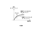
- FIGS. 15A and 15B are graphs schematically showing the relationship between the steering angle and the yaw moment generated in the vehicle in this embodiment.
- FIG. 15A shows the relationship when the vehicle is traveling at medium speed
- FIG. 15B shows the relationship when the vehicle is traveling at low speed.
- the yaw moment generated in the vehicle can be increased by the amount of the yaw moment generated by the braking, and the increase amount of the yaw moment is larger at low speeds than at medium speeds.
- the brake pressure is calculated based on the total control amount obtained by adding the FB control amount calculated based on the vehicle behavior (lateral G and yaw rate) to the FF control amount calculated based on the steering input (steering angle). Controls the brake pressure based only on the FF control amount calculated based on the steering input (steering angle) without adding the FB control amount calculated based on the vehicle behavior (lateral G and yaw rate). It is also possible to assist in turning. Even with this configuration, the present invention is realized.
- the present invention is not limited to the embodiments described above.
- the total control amount is calculated by adding the FF control amount and the FB control amount, but it is also possible to calculate the total control amount by multiplying the FF control amount and the FB control amount.
- an estimated vehicle speed estimated based on the detection value of the wheel speed sensor may be used.
- the FF control amount calculation unit 18 invalidates the FF pressure increase amount ⁇ P 1 ff of the FR inner wheel at FR turning and the FF pressure increase amount ⁇ P 2 ff of the RR inner ring at high vehicle speed, thereby steering at high vehicle speed.
- the FF pressure increase amount of the turning inner wheel may be invalidated even when the steering speed is extremely high or at the time of ABS operation.
- the turning control device for a vehicle of the present invention it is possible to achieve both the control for stabilizing the yaw moment generated in the vehicle body and the control for improving the response of steering. As a result, even if the vehicle is traveling at a low speed, the driver's turning intention is reflected in good response, and the steering feel is improved. In addition, the turning performance of the vehicle is improved, and the road surface tracking performance is improved.
- Vehicle turning control device 2 Brake control unit 3 Steering angle sensor (steering amount detection device) 4 Vehicle speed sensor (vehicle speed detection device) 5 Lateral G sensor (lateral acceleration detector) 6 yaw rate sensor (yaw rate detector) 7 accelerator opening sensor (request torque detection device) 8 ⁇ calculation unit (road surface friction estimation device) 10 Brake device (braking control device) 11 steering angle reference yaw rate calculation unit 12 steady state reference yaw rate calculation unit 13 steady state yaw rate deviation calculation unit 14 lateral G reference yaw rate calculation unit 15 correction unit 17 braking force control amount calculation unit 18 FF control amount calculation unit (second braking force control amount calculation Department) 19 FB control amount calculation unit (1st braking force control amount calculation unit) 23 Assist amount calculator (Assist amount setting device) 31 Allocation coefficient HB1 calculation unit (first correction regulation unit) 33 Correction coefficient HS1 calculation unit (second correction restriction unit) 34 Correction coefficient HS2 calculation unit (third correction restriction unit) 35 Correction coefficient
Abstract
Description
本願は、2010年03月04日に、日本国に出願された特願2010-047835号と、特願2010-047836号と、特願2010-047837号と、特願2010-047838号とに基づき優先権を主張し、その内容をここに援用する。 The present invention relates to a turning control device of a vehicle that controls turning of the vehicle using braking.
The present application is based on Japanese Patent Application No. 2010-047835, Japanese Patent Application No. 2010-047836, Japanese Patent Application No. 2010-047837, and Japanese Patent Application No. 2010-047838 filed on Mar. 4, 2010. Claim priority and its contents are incorporated here.
(1)本発明の車両の旋回制御装置は、車両の走行状態に基づいて前記車両の左右車輪に制動力を付与することにより車体にヨーモーメントを発生可能である。この車両の旋回制御装置は、車両の操舵量を検知する操舵量検知装置と、前記車両の車速を検知または推定する車速検知装置と、前記車両の左右方向の加速度を検知する横加速度検知装置と、前記車両のヨーレートを検知するヨーレート検知装置と、前記横加速度検知装置および前記車速検知装置の検知信号に基づいて第1規範ヨーレートを算出する制御量演算部と、前記操舵量検知装置および前記車速検知装置の検知信号に基づいて前記第1規範ヨーレートを増加方向に補正する補正量を決定し、この補正量にしたがって前記第1規範ヨーレートから第2規範ヨーレートを算出する補正部と、前記第2規範ヨーレートと前記ヨーレート検知装置により検知された実ヨーレートとのヨーレート偏差を算出し、前記ヨーレート偏差を打ち消す方向への第1の制動力制御量を決定する第1制動力制御量演算部と、前記第1制動力制御量演算部により決定された前記制動力制御量に基づいて前記制動力を制御する制動制御装置と、を備える。前記補正部は、所定の運転状態を判別した際に前記第1規範ヨーレートを補正する際の前記補正量を低減する複数の補正規制部を備える。 In the turning control device for a vehicle according to the present invention, the following means are adopted in order to solve the above-mentioned problems.
(1) The turning control device of a vehicle according to the present invention can generate a yaw moment on the vehicle body by applying a braking force to the left and right wheels of the vehicle based on the traveling state of the vehicle. The turning control device of the vehicle includes a steering amount detection device that detects a steering amount of the vehicle, a vehicle speed detection device that detects or estimates the vehicle speed of the vehicle, and a lateral acceleration detection device that detects an acceleration in the lateral direction of the vehicle. A yaw rate detection device for detecting a yaw rate of the vehicle, a control amount calculation unit for calculating a first reference yaw rate based on detection signals of the lateral acceleration detection device and the vehicle speed detection device, the steering amount detection device and the vehicle speed A correction unit which determines a correction amount for correcting the first standard yaw rate in the increasing direction based on a detection signal of the detection device, and calculates a second standard yaw rate from the first standard yaw rate according to the correction amount; Method of canceling a yaw rate deviation by calculating a yaw rate deviation between a reference yaw rate and an actual yaw rate detected by the yaw rate detecting device A first braking force control amount computing unit that determines a first braking force control amount, and braking that controls the braking force based on the braking force control amount determined by the first braking force control amount computing unit And a controller. The correction unit includes a plurality of correction regulation units that reduce the correction amount when correcting the first reference yaw rate when determining a predetermined driving state.
さらに、補正部によって、車体の状況や路面状況に応じてヨーレートの収束性が向上し、車両が低速であっても操舵に対する車両のトレース性が向上し、車両挙動の安定性を制御できる。 According to the vehicle turning control device described in (1), the first reference yaw rate calculated based on the lateral acceleration and the vehicle speed is corrected in the increasing direction to calculate the second reference yaw rate, and the second reference yaw rate is calculated. Since the braking force can be controlled in the direction to cancel the yaw rate deviation between the wheel speed and the actual yaw rate to generate the yaw moment, the turning property is improved even in the normal turning, and the steering response is improved.
Furthermore, the correction unit improves the convergence of the yaw rate according to the condition of the vehicle body and the condition of the road surface, improves the traceability of the vehicle for steering even when the vehicle is at low speed, and can control the stability of the vehicle behavior.
<第1実施形態>
初めに、この発明の第1実施形態に係る車両の旋回制御装置を図1から図10の図面を参照して説明する。
図1は、第1実施形態に係る車両の旋回制御装置における制御ブロック図である。
本実施形態の車両の旋回制御装置1A(1)は、ブレーキ制御部2と、ブレーキ装置(制動制御装置)10とを備えている。
ブレーキ制御部2は、車両の走行状態に応じて車両の前後左右輪の制動力制御量を決定する。ブレーキ装置10は、ブレーキ制御部2によって決定された各輪の制動力制御量に基づいて、各輪の制動力を制御する。 Hereinafter, an embodiment of a turning control device for a vehicle according to the present invention will be described with reference to the drawings of FIGS. 1 to 15B.
First Embodiment
First, a turning control device for a vehicle according to a first embodiment of the present invention will be described with reference to the drawings in FIGS.
FIG. 1 is a control block diagram of a turning control device of a vehicle according to a first embodiment.
A turning
The
定常規範ヨーレート演算部12は、定常規範ヨーレートゲインテーブル21を参照して車速に応じた定常規範ヨーレートゲインKvを算出し、舵角規範ヨーレートに定常規範ヨーレートゲインKvを乗じて定常規範ヨーレートω_highを算出する。本実施形態における定常規範ヨーレートゲインテーブル21は、横軸が車速、縦軸が定常規範ヨーレートゲインKvであり、車速が大きくなるほど定常規範ヨーレートゲインKvは1に収束し、車速が小さくなるほど定常規範ヨーレートゲインKvが大きくなるように設定されている。 The steering angle reference yaw
The steady state yaw
補正部15は、定常規範ヨーレートω_highと横G規範ヨーレートω_lowとに基づいて限界規範ヨーレート(第2規範ヨーレート)ω_TARを算出する。補正部15における限界規範ヨーレートω_TARの算出方法については後で詳述する。
限界ヨーレート偏差演算部16は、限界規範ヨーレートω_TARからヨーレートセンサ6により検知されたヨーレート(実ヨーレート)を減算し、限界ヨーレート偏差Δωfbを算出する。
FB制御量演算部19は、限界ヨーレート偏差Δωfbに基づいてフィードバック制御量(制動力制御量、以下、FB制御量と略す)を算出し、ブレーキ装置10に指令値として出力する。 The lateral G reference yaw
The
The limit yaw rate
The FB control
図2に示すように、補正部15は、配分係数HB1演算部(第1補正規制部)31、基準限界規範ヨーレート演算部32、補正係数HS1演算部(第2補正規制部)33、補正係数HS2演算部(第3補正規制部)34、補正係数HS3演算部(第4補正規制部)35を備えている。
補正部15では、基準限界規範ヨーレート演算部32において、配分係数HB1演算部31で算出した配分係数HB1と、定常規範ヨーレートω_highと、横G規範ヨーレートω_lowと、に基づいて基準限界規範ヨーレートω_t1が算出される。さらに、この基準限界規範ヨーレートω_t1に、補正係数HS1演算部33で算出した補正係数HS1、および補正係数HS2演算部34で算出した補正係数HS2を乗じ、この値にさらに補正係数HS3演算部35で算出した補正係数HS3を加算することにより、限界規範ヨーレートω_TARが算出される(下記式(1)参照)。なお、配分係数HB1、補正係数HS1、補正係数HS2、および補正係数HS3によって、横G規範ヨーレートω_lowを増加する方向に補正する補正量が決定される。
ω_TAR=ω_t1×HS1×HS2+HS3 ・・・ 式(1)
この限界規範ヨーレートω_TARは、フィードバック制御におけるヨーレートの目標値となる。 Next, a method of calculating the limit reference yaw rate ω_TAR in the
As shown in FIG. 2, the
In the
ω_TAR = ω_t1 × HS1 × HS2 + HS3 ・ ・ ・ Formula (1)
The limit reference yaw rate ω_TAR is a target value of the yaw rate in feedback control.
詳述すると、本実施系形態では、配分係数HB1演算部31により算出された配分係数HB1と、横G規範ヨーレートω_lowと、定常規範ヨーレートω_highとに基づいて、下記式(2)から基準限界規範ヨーレートω_t1を算出する。
ω_t1=HB1×ω_high+(1-HB1)×ω_low ・・・ 式(2)
ここで、配分係数HB1は0から1の数値である。HB1=0の場合には基準限界規範ヨーレートω_t1は横G規範ヨーレートω_lowとなる。一方、HB1=1の場合には基準限界規範ヨーレートω_t1は定常規範ヨーレートω_highとなる。 Then, in the present embodiment, as a method of further developing this and increasing the lateral G reference yaw rate, the lateral G reference yaw rate is corrected so as to be close to the steady reference yaw rate ω_high calculated based on the steering angle reference yaw rate. I decided.
More specifically, in the present embodiment, based on the distribution coefficient HB1 calculated by the distribution coefficient
ω_t1 = HB1 × ω_high + (1-HB1) × ω_low ··· Formula (2)
Here, the distribution coefficient HB1 is a numerical value of 0 to 1. When HB1 = 0, the reference limit reference yaw rate ω_t1 is the lateral G reference yaw rate ω_low. On the other hand, when HB1 = 1, the reference limit reference yaw rate ω_t1 becomes the steady-state reference yaw rate ω_high.
配分係数HB1は、車速に応じて算出される配分係数HB1aと、ヨーレート変化率に応じて算出される配分係数HB1bと、ヨーレート偏差積分に応じて算出される配分係数HB1cと、転舵速度に応じて算出される配分係数HB1dとを乗算して算出される(下記式(3)参照)。
HB1=HB1a×HB1b×HB1c×HB1d ・・・ 式(3)
各配分係数HB1a,HB1b,HB1c,HB1dは、それぞれ図4に示す配分係数テーブル40,41,42,43を参照して算出される。以下に、本実施形態における各配分係数テーブル40,41,42,43を説明する。 Next, the distribution coefficient HB1 calculated in the distribution coefficient
The distribution coefficient HB1 is calculated according to the vehicle speed, the distribution coefficient HB1b calculated according to the yaw rate change rate, the distribution coefficient HB1c calculated according to the yaw rate deviation integral, and the steering speed It is calculated by multiplying the distribution coefficient HB1d calculated as above (refer to the following equation (3)).
HB1 = HB1a × HB1b × HB1c × HB1d ・ ・ ・ Formula (3)
The respective distribution coefficients HB1a, HB1b, HB1c, and HB1d are calculated with reference to distribution coefficient tables 40, 41, 42, and 43 shown in FIG. Below, each distribution coefficient table 40, 41, 42, 43 in this embodiment is demonstrated.
このようなときには、FB制御量演算部19において目標値となる限界規範ヨーレートω_TARを大きくすべきではないので、ヨーレート変化率が大きいときには配分係数HB1bを小さい値にして、限界規範ヨーレートω_TARを大きくしないようにする。 In the distribution coefficient table 41 for calculating the distribution coefficient HB1b, the horizontal axis is the yaw rate change rate, and the vertical axis is the distribution coefficient HB1b. The distribution coefficient table 41 is constant at HB1b = 1 in a region where the yaw rate change rate is small, and the distribution coefficient HB1b gradually decreases as the yaw rate change rate increases when the yaw rate change rate becomes a predetermined value or more. In a region where the rate of change is large, it becomes constant at HB1b = 0. Here, the yaw rate change rate is a temporal change of the actual yaw rate detected by the
In such a case, the limit reference yaw rate ω_TAR as the target value should not be increased in the FB control
これにより、前方障害物からの回避操作やレーンチェンジなどのときの操舵に対する車両の応答性が向上する。
なお、配分係数HB1dは転舵速度に代えて転舵角(転舵量)に基づいて算出してもよい。転舵角が大きいほど、運転者が車両を積極的に曲げたいという操作意志が大きいと推定できるからである。この場合の、転舵角は操舵角と同義である。 When the turning speed is positive, it can be estimated that the driver's operation intention to bend the vehicle is large, so the larger the turning speed, the larger the distribution coefficient HB1d (the maximum value is fixed at HB1d = 1 ), The limit reference yaw rate ω_TAR is increased. This improves the responsiveness of the vehicle to steering. On the other hand, when the turning speed is negative, it can be estimated that the driver wants to converge the operation, so the larger the absolute value of the turning speed, the smaller the distribution coefficient HB1d (the minimum value is HB1d = 0 Constant), limit reference yaw rate ω_TAR should not be increased.
As a result, the responsiveness of the vehicle to steering at the time of an avoidance operation or a lane change from a front obstacle is improved.
The distribution coefficient HB1d may be calculated based on the turning angle (turning amount) instead of the turning speed. This is because it can be estimated that the larger the turning angle, the larger the driver's intention to bend the vehicle positively. The turning angle in this case is synonymous with the steering angle.
この補正係数HS1は、運転者が車両を前荷重にしてステアリングホイールを切ることにより車両を曲げる操作を行うときなどを想定した補正係数である。
図5に示すように、補正係数HS1は、操舵速度に応じて算出される補正係数HS1aと、車両の前荷重に応じて算出される補正係数HS1bとを乗算して算出される(下記式(4)参照)。
HS1=HS1a×HS1b ・・・ 式(4)
車両の前荷重とは車両前方への荷重移動量であり、例えば、車両の前後方向の加速度を検知する図示しない前後加速度センサに基づいて推定することができる。この場合、前後加速度センサは、前後方向への荷重移動量を推定する荷重移動量推定装置と言うことができる。 Next, with reference to FIG. 5, the correction coefficient HS1 calculated in the correction coefficient HS1 calculation unit (second correction restriction unit) 33 will be described.
The correction coefficient HS1 is a correction coefficient on the assumption that the driver performs an operation of bending the vehicle by turning the steering wheel with the vehicle at the front load.
As shown in FIG. 5, the correction coefficient HS1 is calculated by multiplying the correction coefficient HS1a calculated according to the steering speed and the correction coefficient HS1b calculated according to the front load of the vehicle (the following equation See 4).
HS1 = HS1a × HS1b ··· Formula (4)
The front load of the vehicle is the amount of load movement to the front of the vehicle, and can be estimated, for example, based on a longitudinal acceleration sensor (not shown) that detects acceleration in the longitudinal direction of the vehicle. In this case, the longitudinal acceleration sensor can be said to be a load movement amount estimation device that estimates the load movement amount in the front and rear direction.
補正係数HS1aを算出する補正係数テーブル44において、横軸は操舵速度であり、縦軸は補正係数HS1aである。この補正係数HS1aテーブル44は、操舵速度が小さい領域ではHS1a=1で一定となり、操舵速度が所定値以上になると操舵速度が大きくなるにしたがって補正係数HS1aが徐々に小さくなっていき、操舵速度が大きい領域ではHS1a=0で一定となる。
補正係数HS1bを算出する補正係数テーブル45において、横軸は前荷重(車両前方への荷重移動量)であり、縦軸は補正係数HS1bである。この補正係数HS1bテーブル45は、前荷重が小さい領域ではHS1b=1で一定となり、前荷重が所定値以上になると前荷重が大きくなるにしたがって補正係数HS1bが徐々に小さくなっていき、前荷重が大きい領域ではHS1b=0で一定となる。 The correction coefficients HS1a and HS1b are calculated with reference to the correction coefficient tables 44 and 45 shown in FIG. 5, respectively. The correction coefficient tables 44 and 45 in the present embodiment will be described.
In the correction coefficient table 44 for calculating the correction coefficient HS1a, the horizontal axis is the steering speed, and the vertical axis is the correction coefficient HS1a. The correction coefficient HS1a table 44 is constant at HS1a = 1 in a region where the steering speed is small, and the correction coefficient HS1a gradually decreases as the steering speed increases when the steering speed becomes a predetermined value or more. In a large area, it becomes constant at HS1a = 0.
In the correction coefficient table 45 for calculating the correction coefficient HS1b, the horizontal axis is a front load (load moving amount to the front of the vehicle), and the vertical axis is a correction coefficient HS1b. This correction coefficient HS1b table 45 becomes constant at HS1b = 1 in the area where the front load is small, and when the front load becomes a predetermined value or more, the correction coefficient HS1b gradually decreases as the front load increases, and the front load becomes smaller. In a large area, it becomes constant at HS1b = 0.
補正係数HS1を上述のように算出する結果、操舵速度が小さい領域で且つ前荷重が小さい領域では補正係数HS1は1となるので、限界規範ヨーレートω_TARを大きくすることができ、車両の回頭性を向上できる。これに対して、操舵速度および前荷重が大きくなるにしたがって補正係数HS1は1よりも小さくなっていくので、限界規範ヨーレートω_TARを小さくでき、車両挙動の安定性を確保できる。 As described above, when the vehicle is used as a front load and the steering wheel is turned, the vehicle is easily bent, but as the front load increases, the vehicle behavior tends to be unstable, and as the steering speed increases, the vehicle behavior becomes more unstable. It is easy to become. The correction coefficient HS1 is a correction coefficient for adjusting the limit reference yaw rate ω_TAR at the time of such steering.
As a result of calculating the correction coefficient HS1 as described above, since the correction coefficient HS1 is 1 in the region where the steering speed is small and the front load is small, the limit reference yaw rate ω_TAR can be increased, and the turning of the vehicle is improved. It can improve. On the other hand, the correction coefficient HS1 becomes smaller than 1 as the steering speed and the front load increase, so that the limit reference yaw rate ω_TAR can be reduced, and the stability of the vehicle behavior can be ensured.
この補正係数HS2は、車輪と路面との摩擦係数(以下μと略す)が高い路面(以下、高μ路と略す)でレーンチェンジ(操舵をして、車両の進行方向をすぐに元の進行方向に戻す操作)をする場合を想定した補正係数である。
補正係数HS2は、1を最大値として、下記の条件を満たした場合に所定の減少カウント値を初期値から減算し、下記のいずれの条件も満たさない場合に1に向けて所定の増加カウント値を加算するよう構成されるゲインである。条件としては、(a)摩擦係数μが高いと判断されたとき(または高摩擦係数の路面走行に対応する前後または横方向加速度が検出されているとき)、(b)操舵角が大きいと判断されたとき、(c)横G減少率が大きいと判断されたとき、(d)ヨーレート減少率が大きいと判断されたとき、に所定の減少カウント値を減算する。なお、上記条件は、(a)から(d)のうち少なくとも1つまたは複数を任意に組み合わせたものであればよい。特に高摩擦係数時の車両挙動の収束性を考慮すると、上記(a)と、(b)から(d)のいずれかを組合わせて用いることが好ましい。
なお、摩擦係数μは、μ算出部8により算出される。横G減少率とは、横Gの減少速度であり、横Gセンサ5で検知される横Gに基づいて算出する。ヨーレート減少率とは、ヨーレートセンサ6で検知される実ヨーレートの減少速度である。 Next, the correction coefficient HS2 calculated in the correction coefficient HS2 calculation unit (third correction restriction unit) 34 will be described.
This correction coefficient HS2 is used for a lane change (steering is performed immediately on the road surface where the coefficient of friction between the wheel and the road surface (hereinafter referred to as μ) is high). It is a correction coefficient on the assumption that the operation of returning to the direction is performed.
The correction coefficient HS2 takes a maximum value of 1 and subtracts a predetermined decrease count value from the initial value when the following conditions are satisfied, and a predetermined increase count value toward 1 when any of the following conditions is not satisfied. Is a gain configured to add As conditions, (a) when it is judged that the coefficient of friction μ is high (or when longitudinal acceleration or lateral acceleration corresponding to traveling on a road surface with a high coefficient of friction is detected), (b) it is judged that the steering angle is large. When it is determined that (c) the lateral G decrease rate is determined to be large, and (d) the yaw rate decrease rate is determined to be large, a predetermined decrease count value is subtracted. The above condition may be any combination of at least one or more of (a) to (d). In particular, in consideration of the convergence of the vehicle behavior at the time of high coefficient of friction, it is preferable to use any one of the above (a) and (b) to (d) in combination.
The coefficient of friction μ is calculated by the
初めに、ステップS01において、摩擦係数μが閾値μthよりも大きいか否かを判定する。
ステップS01における判定結果が「YES」(μ>μth)である場合には、ステップS02に進み、操舵角δが閾値δthよりも大きいか(δ>δth)、あるいは、横G減少率ΔGが閾値ΔGthよりも大きいか(ΔG>ΔGth)、あるいは、ヨーレート減少率γが閾値γthよりも大きいか(γ>γth)のうち1つでも満たすものがあるか否かを判定する。
ステップS02における判定結果が「YES」である場合には、ステップS03に進み、減算処理により補正係数HS2を決定し、本ルーチンの実行を一旦終了する。この減算処理は、補正係数HS2の初期値から所定の減算カウント値を減算していき、補正係数HS2が0に収束していくようにする。
一方、ステップS01における判定結果が「NO」(μ≦μth)である場合、および、ステップS02における判定結果が「NO」である場合には、ステップS04に進み、加算処理により補正係数HS2を決定し、本ルーチンの実行を一旦終了する。この加算処理は、所定の増加カウント値を加算していき、補正係数HS2が1に収束していくようにする。
なお、補正係数HS2の初期値は0から1の間の所定値とする。 An example of the process of determining the correction coefficient HS2 will be described according to the flowchart of FIG.
First, in step S01, it is determined whether the coefficient of friction μ is larger than a threshold μth.
If the determination result in step S01 is "YES"(.mu.>. Mu.th), the process proceeds to step S02 to determine whether the steering angle .delta. Is larger than the threshold .delta.th (.delta.>. Delta.th) or the lateral G reduction rate .DELTA.G is a threshold It is determined whether there is any one that is larger than ΔGth (ΔG> ΔGth) or that the yaw rate reduction rate γ is larger than the threshold γth (γ> γth).
If the result of the determination in step S02 is "YES", the process proceeds to step S03, the correction coefficient HS2 is determined by subtraction processing, and the execution of this routine is temporarily ended. In this subtraction process, a predetermined subtraction count value is subtracted from the initial value of the correction coefficient HS2 so that the correction coefficient HS2 converges to zero.
On the other hand, if the determination result in step S01 is "NO" (.mu..ltoreq..mu.th) and if the determination result in step S02 is "NO", the process proceeds to step S04, and the correction coefficient HS2 is determined by the addition process. And temporarily end the execution of this routine. In this addition process, a predetermined increase count value is added so that the correction coefficient HS2 converges to one.
The initial value of the correction coefficient HS2 is a predetermined value between 0 and 1.
この補正係数HS3は、運転者がタックインをしたときなどを想定した補正係数である。タックインは、旋回中にアクセルペダルを急に戻したときに車両が前荷重となって旋回方向の内側に入り込む現象であるが、運転者によってはこれを利用して積極的に旋回操作を行う場合がある。しかしながら、このタックインを利用した旋回操作は、車両への要求トルクが大きいとき(換言すると、アクセル開度が大きいとき)からアクセルを開放するときや、車速が大きいときには、車両挙動が不安定になり易い。補正係数HS3は、タックイン時の限界規範ヨーレートω_TARを調整するための補正係数である。
図7に示すように、補正係数HS3は、車速に応じて算出される補正係数HS3aと、車両の要求トルクに応じて算出される補正係数HS3bとを乗算して算出される(下記式(6)参照)。
HS3=HS3a×HS3b ・・・ 式(6)
なお、車両の要求トルクは、アクセル開度センサ7で検知したアクセル開度から算出することができ、アクセル開度が大きくなるにしたがって要求トルクが大きくなる。 Next, with reference to FIG. 7, the correction coefficient HS3 calculated in the correction coefficient HS3 calculation unit (fourth correction restriction unit) 35 will be described.
The correction coefficient HS3 is a correction coefficient on the assumption that the driver tacks in. Tack-in is a phenomenon where when the accelerator pedal is suddenly released while turning, the vehicle becomes a front load and enters the inside of the turning direction, but some drivers use this to make a positive turn operation There is. However, the turning operation using this tack-in makes the vehicle behavior unstable when releasing the accelerator from when the required torque to the vehicle is large (in other words, when the accelerator opening is large) or when the vehicle speed is large. easy. The correction coefficient HS3 is a correction coefficient for adjusting the limit reference yaw rate ω_TAR at the time of tack-in.
As shown in FIG. 7, the correction coefficient HS3 is calculated by multiplying the correction coefficient HS3a calculated according to the vehicle speed by the correction coefficient HS3b calculated according to the required torque of the vehicle (the following equation (6 )reference).
HS3 = HS3a × HS3b ··· Formula (6)
The required torque of the vehicle can be calculated from the accelerator opening detected by the
補正係数HS3aを算出する補正係数テーブル51において、横軸は車速であり、縦軸は補正係数HS3aである。この補正係数HS3aテーブル51は、車速が所定値よりも小さい領域ではHS3aは正の一定値であり、車速が前記所定値以上になると車速が大きくなるにしたがって補正係数HS3aが徐々に小さくなっていき、所定速度V0を越えると負の値となり、車速が非常に大きい領域ではHS3aは負の一定値となる。 The correction coefficients HS3a and HS3b are calculated with reference to correction coefficient tables 51 and 52 shown in FIG. 7, respectively. The correction coefficient tables 51 and 52 in the present embodiment will be described.
In the correction coefficient table 51 for calculating the correction coefficient HS3a, the horizontal axis is the vehicle speed, and the vertical axis is the correction coefficient HS3a. In the correction coefficient HS3a table 51, HS3a is a positive constant value in a region where the vehicle speed is smaller than a predetermined value, and the correction coefficient HS3a gradually decreases as the vehicle speed increases when the vehicle speed becomes equal to or higher than the predetermined value. When it exceeds the predetermined speed V0, it becomes a negative value, and in a region where the vehicle speed is very high, HS3a becomes a negative constant value.
また、要求トルクが所定値T0以下の場合(すなわち、タックイン状態であると判断されるとき)であって、かつ車速がV0よりも小さいときには、補正係数HS3が正の値となるので、限界規範ヨーレートω_TARを大きくできる。一方、要求トルクが所定値T0以下の場合であって、かつ車速がV0以上のときには、補正係数HS3が負の値となるので、限界規範ヨーレートω_TARを小さくできる。さらに、車速がV0よりも小さい場合であって、かつ要求トルクが同じときには、車速が小さいほど補正係数H3を正値の大きな値にして、限界規範ヨーレートω_TARを大きくできる。これにより、車速が低中速のタックイン時の、車両の回頭性を向上させられる。特に、車速が小さいときほどタックイン時の車両の回頭性が向上する。一方、車速がV0以上の場合であって、かつ要求トルクが同じときには、車速が大きいほど補正係数H3を負値の大きな値にして、限界規範ヨーレートω_TARを小さくできる。これにより、車速が大きいときに過大なヨーモーメントが発生してオーバーステア状態となるのを抑制でき、車両の挙動が不安定になるのを防止できる。 By setting correction coefficient tables 51 and 52 in this manner, correction coefficient HS3 is obtained regardless of the magnitude of the vehicle speed when the required torque is equal to or greater than predetermined value T0 (that is, when it is determined not to be in the tack-in state). Becomes 0, and it is possible not to correct the limit reference yaw rate ω_TAR.
Further, when the required torque is less than or equal to the predetermined value T0 (ie, when it is determined that the vehicle is in the tack-in state) and the vehicle speed is smaller than V0, the correction coefficient HS3 takes a positive value. The yaw rate ω_TAR can be increased. On the other hand, when the required torque is equal to or less than the predetermined value T0 and the vehicle speed is equal to or more than V0, the correction coefficient HS3 has a negative value, so that the limit reference yaw rate ω_TAR can be reduced. Furthermore, when the vehicle speed is smaller than V0 and the required torque is the same, the limit reference yaw rate ω_TAR can be increased by setting the correction coefficient H3 to a larger positive value as the vehicle speed decreases. As a result, it is possible to improve the turning performance of the vehicle when tacking in at a low or medium speed. In particular, the turning performance of the vehicle at the time of tack-in improves as the vehicle speed decreases. On the other hand, when the vehicle speed is V0 or more and the required torque is the same, the limit reference yaw rate ω_TAR can be reduced by setting the correction coefficient H3 to a large negative value as the vehicle speed increases. As a result, when the vehicle speed is high, it is possible to suppress the occurrence of an excessive yaw moment and the oversteer state, and to prevent the behavior of the vehicle from becoming unstable.
FB制御量演算部19では、限界ヨーレート偏差演算部16で演算された限界ヨーレート偏差Δωfbに基づいて、FR旋回内輪のFB増圧量ΔP1fb、前輪側の旋回外輪(以下、FR旋回外輪と略す)のFB増圧量ΔP3fb、RR旋回内輪のFB増圧量ΔP2fb、および後輪側の旋回外輪(以下、RR旋回外輪と略す)のFB増圧量ΔP4fbを算出する。これらΔP1fb、ΔP3fb、ΔP2fb、およびΔP4fbが第1の制動力制御量である。なお、以降の旋回方向は、偏差Δωfbの符号が正で、かつ規範ヨーレートおよび実ヨーレートがともに正の場合を例に説明する。 Next, with reference to FIG. 8, the calculation of the brake control amount (hereinafter referred to as the FB control amount) executed in the FB control
In the FB control
ブレーキ装置10は、入力した各輪の制御量に応じて、各輪のブレーキ圧を制御する。 Then, the FB control
The
また、横G規範ヨーレートω_lowを増加する方向に補正して限界規範ヨーレートω_TARとしているので、FB制御量演算部19における目標値を大きくすることができ、車両の回頭性が向上する。これにより、車両を走路に沿って旋回させることが可能となり、路面追従性能(トレース性)が向上する。 According to the turning control device of the vehicle of the present embodiment, the lateral G reference yaw rate ω_low is corrected in the increasing direction in association with the steady reference yaw rate ω_high calculated based on the steering angle by the
In addition, since the lateral G reference yaw rate ω_low is corrected in the increasing direction and set as the limit reference yaw rate ω_TAR, the target value in the FB control
次に、この発明に係る車両の旋回制御装置の第2実施形態を図9および図10の図面を参照して説明する。
図9は、第2実施形態に係る車両の旋回制御装置1B(1)における制御ブロック図である。前述した第1実施形態の車両の旋回制御装置1Aでは、限界規範ヨーレートω_TARと実ヨーレートとの偏差(すなわち、限界ヨーレート偏差Δωfb)を打ち消す方向に制御量(FB制御量)を求め、このFB制御量のみでブレーキ圧を制御するようにしている。これに対し、第2実施形態の旋回制御装置1Bでは、操舵角と車速に基づいてフィードフォワード制御量(以下、FF制御量と略す)を算出し、前記FB制御量とFF制御量とを加算して得た値を総制御量とし、この総制御量に基づいて各輪のブレーキ圧を制御する。
以下、第2実施形態に係る車両の旋回制御装置について説明するが、図9の制御ブロック図においてフィードバック制御系、すなわち、舵角規範ヨーレート演算部11、定常規範ヨーレート演算部12、横G規範ヨーレート演算部14、補正部15、限界ヨーレート偏差演算部16、FB制御量演算部19については第1実施形態と同じであるので、同一態様部分に同一符号を付して説明を省略する。以下、第1実施形態との相違点をフィードフォワード制御系を中心に説明する。 Second Embodiment
Next, a second embodiment of the turning control device for a vehicle according to the present invention will be described with reference to the drawings of FIG. 9 and FIG.
FIG. 9 is a control block diagram of the turning
Hereinafter, the turning control device of the vehicle according to the second embodiment will be described. In the control block diagram of FIG. 9, a feedback control system, that is, a steering angle reference yaw
制動力制御量演算部17は、FF制御量演算部18において定常ヨーレート偏差Δωffに基づいてフィードフォワード制御量を算出し、FB制御量演算部19において限界ヨーレート偏差Δωfbに基づいてフィードバック制御量(FB制御量)を算出し、さらにFF制御量とFB制御量を加算して総制御量を算出し、ブレーキ装置10に指令値として出力する。 The steady-state yaw rate
The braking force control
FF制御量演算部18におけるFF制御量の算出について説明する。
まず、操舵角センサ3で検知された操舵角に基づいて、前輪側の旋回内輪(以下、FR旋回内輪と略す)と後輪側の旋回内輪(以下、RR旋回内輪と略す)に対する増圧配分を決定する。次いで、この増圧配分に基づいて、FR旋回内輪に対する増圧係数K1frとRR旋回内輪に対する増圧係数K1rrとを算出する。ここで、操舵による荷重移動が大きい場合には、操舵角に応じて、FR旋回内輪に対する増圧係数K1frが大きくなるように設定してもよい。
そして、FR旋回内輪に対する増圧係数K1frとRR旋回内輪に対する増圧係数K1rrに基づいて、FR旋回内輪に対するFF増圧量ΔP1ffの算出と、RR旋回内輪に対するFF増圧量ΔP2ffの算出が、並行して実施される。なお、これらΔP1ffとΔP2ffとが、第2の制動力制御量である。 Next, with reference to FIG. 10, the brake control amount calculation performed in the braking force control
The calculation of the FF control amount in the FF control
First, based on the steering angle detected by the
The calculation of the FF pressure increase amount ΔP1ff for the FR inner race in parallel with the calculation of the FF pressure increase amount ΔP2ff for the RR inner race in parallel based on the pressure increase coefficient K1fr for the FR inner race and the pressure increase coefficient K1rr for the RR inner race To be implemented. Note that these ΔP1ff and ΔP2ff are second braking force control amounts.
定常ヨーレート偏差演算部13で演算された定常ヨーレート偏差Δωffに、RR旋回内輪に対する増加係数K1rrを乗じて、RR旋回内輪に対する定常ヨーレート偏差Δω2ffを算出する。
次に、第2増圧量テーブル64を参照し、RR旋回内輪に対する定常ヨーレート偏差Δω2ffに応じて、RR旋回内輪のブレーキ液圧増圧量ΔP2ffkを算出する。第2増圧量テーブル64は第1増圧量テーブル60と同じであるので説明を省略する。
次に、第2リミット処理部65において、RR旋回内輪のブレーキ液圧増圧量ΔP2ffkが上限値を超えないようにリミット処理を行う。上限値は、第2上限値算出部66によって算出される。第2上限値算出部66は第1上限値算出部62と同じである。
次に、リミット処理されたRR旋回内輪のブレーキ液圧増圧量ΔP2ffkに、第2ゲインテーブル67により算出したゲインを乗じて、RR旋回内輪に対するFF増圧量ΔP2ffを算出する。第2ゲインテーブル67は第1ゲインテーブル63と同じであるので、説明を省略する。本実施形態において、第2ゲインテーブル67は無効化機構を構成する。 The calculation of the FF pressure increase amount ΔP2ff with respect to the RR turning inner ring is the same as the calculation of the FF pressure increasing amount ΔPfr1 with respect to the FR turning inner wheel, and therefore will be briefly described.
The steady state yaw rate deviation Δω ff calculated by the steady state yaw rate
Next, with reference to the second pressure increase amount table 64, the brake fluid pressure increase amount ΔP2ffk of the RR inner wheel is calculated according to the steady-state yaw rate deviation Δω2ff with respect to the RR inner wheel. Since the second pressure increase amount table 64 is the same as the first pressure increase amount table 60, the description will be omitted.
Next, in the second
Next, the FF hydraulic pressure increase amount ΔP2ff for the RR inner race is calculated by multiplying the brake hydraulic pressure increase amount ΔP2ffk for the RR inner race which has been subjected to the limit processing by the gain calculated by the second gain table 67. The second gain table 67 is the same as the first gain table 63, so the description thereof is omitted. In the present embodiment, the second gain table 67 constitutes an invalidation mechanism.
内輪減圧量算出部70では、第1減圧率テーブル71を参照して車速に応じた減圧率を算出するとともに、第2減圧率テーブル72を参照して横Gに応じた減圧率を算出し、これら減圧率を乗じることで総減圧率を算出する。 In addition, the FF control
The inner ring pressure reduction
これにより、総減圧率は、走行時の車速および横Gに応じて、0から1の間の値に設定される。
そして、このようにして求めた総減圧率にブレーキ装置10のマスタシリンダ圧を乗じ、さらにマイナス1を乗じて内輪減圧量ΔPdを求める。
FB制御量演算部19におけるFB制御量の算出については第1実施形態と同じであるので説明を省略する。 In the second pressure reduction rate table 72, the horizontal axis is horizontal G, the vertical axis is a pressure reduction rate, and in a region where the horizontal G is small, the pressure reduction rate becomes constant at 0, and when the horizontal G becomes a predetermined value or more, the horizontal G is As the pressure increases, the pressure reduction rate gradually increases. In a region where the lateral G is large, the pressure reduction rate becomes constant at 1.
Thereby, the total pressure reduction rate is set to a value between 0 and 1 according to the vehicle speed and the lateral G at the time of traveling.
Then, the total pressure reduction rate thus obtained is multiplied by the master cylinder pressure of the
The calculation of the FB control amount in the FB control
ブレーキ装置10は、入力した各輪の制御量に応じて、各輪のブレーキ圧を制御する。 Then, the braking force control
The
また、横G規範ヨーレートω_lowを増加する方向に補正して限界規範ヨーレートω_TARとしているので、FB制御量演算部19における目標値を大きくすることができ、車両の回頭性が向上する。これにより、車両を走路に沿って旋回させることが可能となり、路面追従性能(トレース性)が向上する。 According to the turning control device for a vehicle of the present embodiment, the lateral G reference yaw rate ω_low is related to the steady reference yaw rate ω_high calculated by the
In addition, since the lateral G reference yaw rate ω_low is corrected in the increasing direction and set as the limit reference yaw rate ω_TAR, the target value in the FB control
次に、この発明に係る車両の旋回制御装置の第3実施形態を図11および図12の図面を参照して説明する。本実施形態が上述の第1実施形態と異なる点は、第1実施形態では、タックイン状態か否かを要求トルクに基づいて判定しているのに対し、第3実施形態では、アクセルペダルまたはアクセル開度の戻し速度(以下、戻し速度と略す)に基づいてタックイン状態か否かを判定している点、あるいは、要求トルクと戻し速度の両方に基づいてタックイン状態か否かを判定している点である。すなわち、本実施形態のこの判定方法は、上記第1実施形態に加え、第2実施形態にも適用可能である。以下、これらの判定方法を詳述する。 Third Embodiment
Next, a third embodiment of the turning control device for a vehicle according to the present invention will be described with reference to the drawings of FIG. 11 and FIG. The present embodiment is different from the above-described first embodiment in that in the first embodiment, whether or not it is in the tack-in state is determined based on the required torque, while in the third embodiment, the accelerator pedal or accelerator is Whether or not it is in the tack-in state based on the return speed of the opening (hereinafter referred to as return speed), or whether or not it is in the tack-in state based on both the required torque and the return speed It is a point. That is, this determination method of the present embodiment can be applied to the second embodiment in addition to the first embodiment. Hereinafter, these determination methods will be described in detail.
補正係数HS3cは、図11に示す補正係数テーブル53を参照して算出される。補正係数テーブル53において、横軸は戻し速度であり、縦軸は補正係数HS3cである。この補正係数HS3cテーブル53は、戻し速度が所定値以下の領域では補正係数HS3c=0で一定となり、戻し速度が前記所定値を越えると戻し速度が大きくなるにしたがって補正係数HS3cが徐々に大きくなっていき、最大値Aに収束し一定となる。ここで、前記所定値は、タックイン操作であるか否かの判定閾値となる戻し速度に設定する。
このようにすると、アクセルペダルまたはアクセル開度を戻す速度が前記所定値よりも遅いときにはタックイン状態ではないと判定して、補正係数HS3cを0とすることで補正係数HS3による限界規範ヨーレートω_TARの補正を行わないようにする。一方、アクセルペダルまたはアクセル開度を戻す速度が前記所定値よりも早いときにはタックイン状態であると判定して、車速に応じた補正係数HS3を算出し、補正係数HS3による限界規範ヨーレートω_TARの補正を行う。 When determining whether the vehicle is in the tack-in state based on the return speed, as shown in FIG. 11, the correction coefficient HS3a calculated according to the vehicle speed is multiplied by the correction coefficient HS3c calculated according to the return speed. Then, the correction coefficient HS3 is calculated (HS3 = HS3a × HS3c).
The correction coefficient HS3c is calculated with reference to the correction coefficient table 53 shown in FIG. In the correction coefficient table 53, the horizontal axis is the return speed, and the vertical axis is the correction coefficient HS3c. In the correction coefficient HS3c table 53, the correction coefficient HS3c becomes constant in a region where the return speed is less than a predetermined value, and when the return speed exceeds the predetermined value, the correction coefficient HS3c gradually increases as the return speed increases. And converge to the maximum value A and become constant. Here, the predetermined value is set to a return speed that is a determination threshold value for determining whether the operation is a tuck-in operation.
In this way, it is determined that the vehicle is not in the tack-in state when the speed for returning the accelerator pedal or the accelerator opening is slower than the predetermined value, and the correction coefficient HS3c is set to 0 to correct the limit reference yaw rate ω_TAR by the correction coefficient HS3. Do not do On the other hand, when the speed for returning the accelerator pedal or the accelerator opening is faster than the predetermined value, it is determined that the vehicle is in the tack-in state, the correction coefficient HS3 according to the vehicle speed is calculated, and correction of the limit standard yaw rate ω_TAR by the correction coefficient HS3 is performed. Do.
以下、この発明に係る車両の旋回制御装置の第4実施形態を図13から図15Bの図面を参照して説明する。
図13は、第4実施形態に係る車両の旋回制御装置における制御ブロック図である。
本実施形態の車両の旋回制御装置1C(1)は、ブレーキ制御部2と、ブレーキ装置(制動制御装置)10とを備えている。
ブレーキ制御部2は、車両の走行状態に応じて前後左右輪の制動力制御量を決定する。ブレーキ装置10は、ブレーキ制御部2によって決定された各輪の制動力制御量に基づいて、各輪の制動力を制御する。 Fourth Embodiment
Hereinafter, a fourth embodiment of the turning control device for a vehicle according to the present invention will be described with reference to the drawings in FIG. 13 to FIG. 15B.
FIG. 13 is a control block diagram of the turning control device for a vehicle according to the fourth embodiment.
A turning
The
ブレーキ制御部2は、アシスト量演算部(アシスト量設定装置)23、横G規範ヨーレート演算部14、ヨーレート偏差演算部16、および制動力制御量演算部17を備えている。制動力制御量演算部17は、第2制動力制御演算部(フィードフォワード制御量演算部、以下、FF制御量演算部と略す)18と、第1制動力制御演算部(フィードバック制御量演算部、以下、FB制御量演算部と略す)19と、を備えている。 The
The
このように舵角ゲインテ-ブル24と車速ゲインテーブル25が設定されているので、舵角の絶対値が所定値未満では、車速の如何に関わらずアシスト量Asは0となる。一方、舵角の絶対値が所定値以上になると舵角の絶対値が大きくなるほどアシスト量Asが増大し、且つ、車速が小さいほどアシスト量Asが大きく、車速が大きくなるほどアシスト量Asが減少する。 On the other hand, in the vehicle speed gain table 25 in the present embodiment, the horizontal axis is the vehicle speed, the vertical axis is the vehicle speed gain Kv, and the vehicle speed gain Kv decreases and converges to 1 as the vehicle speed increases, and the vehicle speed gain Kv decreases as the vehicle speed decreases. It is set to be large.
Since the steering angle gain table 24 and the vehicle speed gain table 25 are set as described above, the assist amount As is 0 regardless of the vehicle speed when the absolute value of the steering angle is less than a predetermined value. On the other hand, when the absolute value of the steering angle becomes a predetermined value or more, the assist amount As increases as the absolute value of the steering angle increases, and the assist amount As increases as the vehicle speed decreases and decreases as the vehicle speed increases. .
ヨーレート偏差演算部16は、横G規範ヨーレートω_lowからヨーレートセンサ6により検知されたヨーレート(実ヨーレート)を減算し、ヨーレート偏差Δωfbを算出する。 The lateral G reference yaw
The yaw rate
初めに、FF制御量演算部18におけるFF制御量の算出について説明する。
まず、操舵角センサ3で検知されたステアリングホイールの操舵角に基づいて、車両の前輪側の旋回内輪(以下、FR旋回内輪と略す)と後輪側の旋回内輪(以下、RR旋回内輪と略す)に対する増圧配分を決定する。次いで、この増圧配分に基づいて、FR旋回内輪に対する増圧係数K1frとRR旋回内輪に対する増圧係数K1rrとを算出する。ここで、操舵による荷重移動が大きい場合には、操舵角に応じて、FR旋回内輪に対する増圧係数K1frが大きくなるように設定してもよい。
そして、FR旋回内輪に対する増圧係数K1frとRR旋回内輪に対する増圧係数K1rrとに基づいて、FR旋回内輪に対するFF増圧量ΔP1ffの算出と、RR旋回内輪に対するFF増圧量ΔP2ffの算出とが、並行して実施される。 Next, with reference to FIG. 14, the brake control amount calculation performed in the braking force control
First, calculation of the FF control amount in the FF control
First, based on the steering angle of the steering wheel detected by the
Then, based on the pressure increase coefficient K1fr for the FR inner race and the pressure increase coefficient K1rr for the RR inner race, calculation of the FF pressure increase ΔP1ff for the FR inner race and calculation of the FF pressure increase ΔP2ff for the RR inner race are , Will be implemented in parallel.
次に、第1増圧量テーブル68を参照し、FR旋回内輪に対するアシスト量As1に応じて、FR旋回内輪のブレーキ液圧増圧量ΔP1ffkを算出する。第1増圧量テーブル68において、横軸はアシスト量As1であり、縦軸はブレーキ液圧増圧量ΔP1ffkである。
本実施形態では、FR旋回内輪に対するアシスト量As1が0以下の場合にはブレーキ液圧増圧量ΔP1ffkは0である。一方、FR旋回内輪に対するアシスト量AFAs1が0以上ではアシスト量As1が大きくなるにしたがってブレーキ液圧増圧量ΔP1ffkが増大していく。 First, calculation of the FF pressure increase amount ΔP1ff for the FR turning inner wheel will be described. The assist amount As calculated by the assist
Next, with reference to the first pressure increase amount table 68, the brake hydraulic pressure increase amount ΔP1ffk of the FR turning inner wheel is calculated according to the assist amount As1 for the FR turning inner wheel. In the first pressure increase amount table 68, the horizontal axis is the assist amount As1, and the vertical axis is the brake fluid pressure increase amount ΔP1ffk.
In the present embodiment, the brake hydraulic pressure increase amount ΔP1ffk is zero when the assist amount As1 for the FR turning inner wheel is equal to or less than zero. On the other hand, when the assist amount AFAs1 with respect to the FR turning inner wheel is 0 or more, the brake hydraulic pressure pressure increase amount ΔP1ffk increases as the assist amount As1 increases.
このように車速に応じたゲインを乗じる結果、車速が大きいときには、FR旋回内輪のFF増圧量ΔP1ffは0となる。換言すると、高車速時にはFR旋回内輪のFF増圧量ΔP1ffが無効とされる。これにより、高車速時に旋回アシストブレーキに起因して車両挙動が不安定になるのを防止することができる。本実施形態において、第1ゲインテーブル63は無効化機構を構成する。なお、車速に応じたゲインを乗じるのに替えて、高車速ほど値が低くなる任意の制限値を与え、この制限値をΔPlffが上回らないように設定してもよい。 Next, the FF hydraulic pressure increase amount ΔP1ff for the FR turning inner wheel is calculated by multiplying the brake hydraulic pressure pressure increasing amount ΔP1ffk of the FR turning inner ring subjected to the limit processing by a gain according to the vehicle speed. The gain according to the vehicle speed is calculated based on the first gain table 63. In the first gain table 63, the horizontal axis represents the vehicle speed, and the vertical axis represents the gain. In a region where the vehicle speed is small, the gain is constant at 1. On the other hand, when the vehicle speed becomes a predetermined value or more, the gain gradually decreases as the vehicle speed increases, and in a region where the vehicle speed is large, the gain becomes constant at 0.
As a result of multiplying the gain according to the vehicle speed as described above, when the vehicle speed is high, the FF pressure increase amount ΔP1ff of the FR turning inner wheel becomes zero. In other words, when the vehicle speed is high, the FF pressure increase amount ΔP1ff of the FR turning inner wheel is made invalid. This makes it possible to prevent the behavior of the vehicle from becoming unstable due to the turn assist brake at high vehicle speeds. In the present embodiment, the first gain table 63 constitutes an invalidation mechanism. Here, instead of multiplying the gain according to the vehicle speed, an arbitrary limit value may be given such that the value decreases as the vehicle speed increases, and the limit value may be set so that ΔPlff does not exceed.
アシスト量演算部23で演算されたアシスト量Asに、RR旋回内輪に対する増加係数K1rrを乗じて、RR旋回内輪に対するアシスト量As2を算出する。
次に、第2増圧量テーブル69を参照し、RR旋回内輪に対するアシスト量As2に応じて、RR旋回内輪のブレーキ液圧増圧量ΔP2ffkを算出する。第2増圧量テーブル69は、第1増圧量テーブル68と同じであるので説明を省略する。
次に、第2リミット処理部65において、RR旋回内輪のブレーキ液圧増圧量ΔP2ffkが上限値を超えないようにリミット処理を行う。上限値は、第2上限値算出部66によって算出される。第2上限値算出部66は、第1上限値算出部62と同じである。
次に、リミット処理されたRR旋回内輪のブレーキ液圧増圧量ΔP2ffkに、第2ゲインテーブル67により算出したゲインを乗じて、RR旋回内輪に対するFF増圧量ΔP2ffを算出する。第2ゲインテーブル67は、第1ゲインテーブル63と同じであるので、説明を省略する。本実施形態において、第2ゲインテーブル67は無効化機構を構成する。 The calculation of the FF pressure increase amount ΔP2ff with respect to the RR turning inner ring is the same as the calculation of the FF pressure increasing amount ΔPfr1 with respect to the FR turning inner wheel, and therefore will be briefly described.
An assist amount As2 for the RR inner wheel is calculated by multiplying the assist amount As calculated by the
Next, with reference to the second pressure increase amount table 69, the brake hydraulic pressure increase amount ΔP2ffk of the RR inner wheel is calculated according to the assist amount As2 for the RR inner wheel. The second pressure increase amount table 69 is the same as the first pressure increase amount table 68, so the description will be omitted.
Next, in the second
Next, the FF hydraulic pressure increase amount ΔP2ff for the RR inner race is calculated by multiplying the brake hydraulic pressure increase amount ΔP2ffk for the RR inner race which has been subjected to the limit processing by the gain calculated by the second gain table 67. The second gain table 67 is the same as the first gain table 63, so the description will be omitted. In the present embodiment, the second gain table 67 constitutes an invalidation mechanism.
内輪減圧量算出部70では、第1減圧率テーブル71を参照して車速に応じた減圧率を算出するとともに、第2減圧率テーブル72を参照して横Gに応じた減圧率を算出し、これら減圧率を乗じることで総減圧率を算出する。
第1減圧率テーブル71において、横軸は車速であり、縦軸は減圧率であって、車速が小さい領域では減圧率=0で一定となり、車速が所定値以上になると車速が大きくなるにしたがって減圧率が徐々に大きくなっていき、車速が大きい領域では減圧率=1で一定となる。
第2減圧率テーブル72において、横軸は横Gであり、縦軸は減圧率であって、横Gが小さい領域では減圧率=0で一定となり、横Gが所定値以上になると横Gが大きくなるにしたがって減圧率が徐々に大きくなっていき、横Gが大きい領域では減圧率=1で一定となる。
これにより、総減圧率は、走行時の車速および横Gに応じて、0から1の間の値に設定されることとなる。
そして、このようにして設定された総減圧率にブレーキ装置10のマスタシリンダ圧を乗じ、さらにマイナス1を乗じて内輪減圧量ΔPdを求める。 In addition, the FF control
The inner ring pressure reduction
In the first pressure reduction rate table 71, the horizontal axis is the vehicle speed, the vertical axis is the pressure reduction rate, and the pressure reduction rate becomes constant at 0 when the vehicle speed is small. The pressure reduction rate gradually increases, and the pressure reduction rate becomes constant at 1 in a region where the vehicle speed is large.
In the second pressure reduction rate table 72, the horizontal axis is horizontal G, the vertical axis is a pressure reduction rate, and in a region where the horizontal G is small, the pressure reduction rate becomes constant at 0, and when the horizontal G becomes a predetermined value or more, the horizontal G is As the pressure increases, the pressure reduction rate gradually increases. In a region where the lateral G is large, the pressure reduction rate becomes constant at 1.
Accordingly, the total pressure reduction rate is set to a value between 0 and 1 according to the vehicle speed and the lateral G at the time of traveling.
Then, the total pressure reduction rate set in this way is multiplied by the master cylinder pressure of the
FB制御量演算部19では、ヨーレート偏差演算部16で演算されたヨーレート偏差Δωfbに基づいて、FR旋回内輪のFB増圧量ΔP1fb、前輪側の旋回外輪(以下、FR旋回外輪と略す)のFB増圧量ΔP3fb、RR旋回内輪のFB増圧量ΔP2fb、および後輪側の旋回外輪(以下、RR旋回外輪と略す)のFB増圧量ΔP4fbを算出する。なお、以降の旋回方向は偏差Δωfbの符号が正で、規範ヨーレートおよび実ヨーレートがともに正の場合を例に説明する。 Next, calculation of the FB control amount in the FB control
In the FB control
ブレーキ装置10は、入力された各輪の制御量に応じて、各輪のブレーキ圧を制御する。 Then, the braking force control
The
なお、この発明は前述した実施例に限られるものではない。
例えば、前述した実施例2では、FF制御量とFB制御量を加算して総制御量を算出したが、FF制御量とFB制御量を乗算して総制御量を算出することも可能である。
また、車速センサの検出値に替えて、車輪速センサの検出値に基づき推定される推定車速を用いてもよい。 [Other Embodiments]
The present invention is not limited to the embodiments described above.
For example, in the second embodiment described above, the total control amount is calculated by adding the FF control amount and the FB control amount, but it is also possible to calculate the total control amount by multiplying the FF control amount and the FB control amount. .
Further, instead of the detection value of the vehicle speed sensor, an estimated vehicle speed estimated based on the detection value of the wheel speed sensor may be used.
2 ブレーキ制御部
3 操舵角センサ(操舵量検知装置)
4 車速センサ(車速検知装置)
5 横Gセンサ(横加速度検知装置)
6 ヨーレートセンサ(ヨーレート検知装置)
7 アクセル開度センサ(要求トルク検知装置)
8 μ算出部(路面摩擦推定装置)
10 ブレーキ装置(制動制御装置)
11 舵角規範ヨーレート演算部
12 定常規範ヨーレート演算部
13 定常ヨーレート偏差演算部
14 横G規範ヨーレート演算部
15 補正部
17 制動力制御量演算部
18 FF制御量演算部(第2制動力制御量演算部)
19 FB制御量演算部(第1制動力制御量演算部)
23 アシスト量演算部(アシスト量設定装置)
31 配分係数HB1演算部(第1補正規制部)
33 補正係数HS1演算部(第2補正規制部)
34 補正係数HS2演算部(第3補正規制部)
35 補正係数HS3演算部(第4補正規制部)
63 第1ゲインテーブル(無効化機構)
67 第2ゲインテーブル(無効化機構) 1 (1A, 1B, 1C) Vehicle turning
4 Vehicle speed sensor (vehicle speed detection device)
5 Lateral G sensor (lateral acceleration detector)
6 yaw rate sensor (yaw rate detector)
7 accelerator opening sensor (request torque detection device)
8 μ calculation unit (road surface friction estimation device)
10 Brake device (braking control device)
11 steering angle reference yaw
19 FB control amount calculation unit (1st braking force control amount calculation unit)
23 Assist amount calculator (Assist amount setting device)
31 Allocation coefficient HB1 calculation unit (first correction regulation unit)
33 Correction coefficient HS1 calculation unit (second correction restriction unit)
34 Correction coefficient HS2 calculation unit (third correction restriction unit)
35 Correction coefficient HS3 calculation unit (fourth correction restriction unit)
63 1st gain table (invalidation mechanism)
67 2nd gain table (invalidation mechanism)
Claims (19)
- 車両の走行状態に基づいて前記車両の左右車輪に制動力を付与することにより車体にヨーモーメントを発生可能な車両の旋回制御装置であって、
前記車両の旋回制御装置は、
車両の操舵量を検知する操舵量検知装置と、
前記車両の車速を検知または推定する車速検知装置と、
前記車両の左右方向の加速度を検知する横加速度検知装置と、
前記車両のヨーレートを検知するヨーレート検知装置と、
前記横加速度検知装置および前記車速検知装置の検知信号に基づいて第1規範ヨーレートを算出する制御量演算部と、
前記操舵量検知装置および前記車速検知装置の検知信号に基づいて前記第1規範ヨーレートを増加方向に補正する補正量を決定し、この補正量にしたがって前記第1規範ヨーレートから第2規範ヨーレートを算出する補正部と、
前記第2規範ヨーレートと前記ヨーレート検知装置により検知された実ヨーレートとのヨーレート偏差を算出し、前記ヨーレート偏差を打ち消す方向への第1の制動力制御量を決定する第1制動力制御量演算部と、
前記第1制動力制御量演算部により決定された前記第1の制動力制御量に基づいて前記制動力を制御する制動制御装置と、
を備え、
前記補正部は、所定の運転状態を判別した際に前記第1規範ヨーレートを補正する際の前記補正量を低減する複数の補正規制部を備えることを特徴とする車両の旋回制御装置。 A turning control device of a vehicle capable of generating a yaw moment on a vehicle body by applying a braking force to left and right wheels of the vehicle based on a traveling state of the vehicle.
The turning control device of the vehicle
A steering amount detection device for detecting a steering amount of a vehicle;
A vehicle speed detection device for detecting or estimating the vehicle speed of the vehicle;
A lateral acceleration detection device for detecting an acceleration in the left and right direction of the vehicle;
A yaw rate detection device for detecting a yaw rate of the vehicle;
A control amount calculation unit that calculates a first reference yaw rate based on detection signals of the lateral acceleration detection device and the vehicle speed detection device;
A correction amount for correcting the first reference yaw rate in the increasing direction is determined based on detection signals of the steering amount detection device and the vehicle speed detection device, and a second reference yaw rate is calculated from the first reference yaw rate according to the correction amount. The correction unit to
A first braking force control amount computing unit that calculates a yaw rate deviation between the second standard yaw rate and an actual yaw rate detected by the yaw rate detection device, and determines a first braking force control amount in a direction to cancel the yaw rate deviation. When,
A braking control device that controls the braking force based on the first braking force control amount determined by the first braking force control amount calculation unit;
Equipped with
The vehicle turning control device according to claim 1, wherein the correction unit includes a plurality of correction regulation units that reduce the correction amount when correcting the first reference yaw rate when determining a predetermined driving state. - 前記補正部は、車速が大きいほど前記第2規範ヨーレートが小さくなるように前記補正量を決定する第1補正規制部を有することを特徴とする請求項1に記載の車両の旋回制御装置。 The vehicle turning control device according to claim 1, wherein the correction unit includes a first correction regulation unit that determines the correction amount such that the second reference yaw rate decreases as the vehicle speed increases.
- 前記車両の前後方向への荷重移動量を推定する荷重移動量推定装置を更に備え、
前記補正部は、前記荷重移動量推定装置が推定した前方への荷重移動量が大きいほど前記第2規範ヨーレートが小さくなるように前記補正量を決定する第2補正規制部を有することを特徴とする請求項1または請求項2に記載の車両の旋回制御装置。 The apparatus further comprises a load transfer amount estimation device for estimating a load transfer amount in the front-rear direction of the vehicle,
The correction unit includes a second correction regulation unit that determines the correction amount so that the second reference yaw rate decreases as the forward load movement amount estimated by the load movement amount estimation device increases. The turning control device of a vehicle according to claim 1 or 2. - 前記補正部は、所定のレーンチェンジ条件を満たした場合に前記補正量を低減する第3補正規制部を有することを特徴とする請求項1から請求項3のいずれか1項に記載の車両の旋回制御装置。 The vehicle according to any one of claims 1 to 3, wherein the correction unit includes a third correction regulation unit that reduces the correction amount when a predetermined lane change condition is satisfied. Turning control device.
- 車両の車輪と路面との間の摩擦係数を推定する路面摩擦推定装置を更に備え、
前記第3補正規制部は、前記路面摩擦推定装置により推定された摩擦係数が大きい場合に、前記補正量を低減することを特徴とする請求項4に記載の車両の旋回制御装置。 A road surface friction estimation device for estimating a coefficient of friction between a vehicle wheel and the road surface;
5. The turning control device for a vehicle according to claim 4, wherein the third correction regulating unit reduces the correction amount when the friction coefficient estimated by the road surface friction estimating device is large. - 前記第3補正規制部は、前記操舵量検知装置により検知された操舵量が大きい場合に前記レーンチェンジ条件を満たしたと判定して、前記補正量を低減することを特徴とする請求項4または請求項5に記載の車両の旋回制御装置。 The third correction regulation unit determines that the lane change condition is satisfied when the steering amount detected by the steering amount detection device is large, and reduces the correction amount. 6. A turning control device for a vehicle according to item 5.
- 前記第3補正規制部は、前記ヨーレート検知装置の検知信号に基づいて算出される実ヨーレートの減少率が大きい場合に前記レーンチェンジ条件を満たしたと判定して、前記補正量を低減することを特徴とする請求項4から請求項6のいずれか1項に記載の車両の旋回制御装置。 The third correction regulating unit is characterized in that the correction amount is reduced by determining that the lane change condition is satisfied when the decrease rate of the actual yaw rate calculated based on the detection signal of the yaw rate detection device is large. The turn control device of a vehicle according to any one of claims 4 to 6.
- 前記第3補正規制部は、前記横加速度検知装置の検知信号に基づいて算出される横加速度の減少率が大きい場合に前記レーンチェンジ条件を満たしたと判定して、前記補正量を低減することを特徴とする請求項4から請求項7のいずれか1項に記載の車両の旋回制御装置。 The third correction regulating unit determines that the lane change condition is satisfied when the reduction rate of the lateral acceleration calculated based on the detection signal of the lateral acceleration detecting device is large, and reduces the correction amount. The turning control device for a vehicle according to any one of claims 4 to 7, characterized in that:
- アクセル開度またはアクセルペダル操作量に基づいて要求トルクの大きさを検知する要求トルク検知装置を更に備え、
前記補正部は、前記要求トルク検知装置の検知信号が所定値よりも小さいときに、車速が小さいほど前記第2規範ヨーレートが大きくなるように前記補正量を決定する第4補正規制部を有することを特徴とする請求項1から請求項8のいずれか1項に記載の車両の旋回制御装置。 The system further comprises a required torque detection device that detects the magnitude of the required torque based on the accelerator opening degree or the accelerator pedal operation amount,
The correction unit includes a fourth correction / regulation unit that determines the correction amount so that the second standard yaw rate increases as the vehicle speed decreases when the detection signal of the required torque detection device is smaller than a predetermined value. The vehicle turning control device according to any one of claims 1 to 8, characterized in that - アクセル開度またはアクセルペダル操作量に基づいて要求トルクの大きさを検知する要求トルク検知装置を更に備え、
前記補正部は、アクセル開度を検知するアクセル開度検知装置によりアクセル開度が全閉近傍であることが検知された場合に前記補正量をさらに増加させる第4補正規制部を有することを特徴とする請求項1から請求項8のいずれか1項に記載の車両の旋回制御装置。 The system further comprises a required torque detection device that detects the magnitude of the required torque based on the accelerator opening degree or the accelerator pedal operation amount,
The correction unit is characterized by having a fourth correction restricting unit that further increases the correction amount when it is detected by the accelerator opening detection device that detects the accelerator opening that the accelerator opening is near the fully closed position. The turning control device of a vehicle according to any one of claims 1 to 8. - 前記第4補正規制部は、車速が大きいほど、前記補正量を増加させる調整量を低減することを特徴とする請求項10に記載の車両の旋回制御装置。 11. The turning control device for a vehicle according to claim 10, wherein the fourth correction regulating unit reduces the adjustment amount for increasing the correction amount as the vehicle speed is higher.
- 前記第4補正規制部は、車速が所定速度を越えたときには、前記補正量を減少方向へ調整することを特徴とする請求項10または請求項11に記載の車両の旋回制御装置。 12. The turning control device for a vehicle according to claim 10, wherein the fourth correction regulating unit adjusts the correction amount in a decreasing direction when the vehicle speed exceeds a predetermined speed.
- 前記第4補正規制部は、前記アクセル開度の全閉方向への戻し速度が大きいほど、前記補正量を増加させる調整量を大きくすることを特徴とする請求項10から請求項12のいずれか1項に記載の車両の旋回制御装置。 The fourth correction / regulation unit increases the adjustment amount for increasing the correction amount as the return speed of the accelerator opening in the fully closed direction is larger. A turn control device of a vehicle according to item 1.
- 前記補正部は、前記操舵量検知装置の検知信号に基づいて算出される転舵速度または転舵量が大きいほど前記第2規範ヨーレートが大きくなるように補正量を決定することを特徴とする請求項1から請求項13のいずれか1項に記載の車両の旋回制御装置。 The correction unit determines the correction amount such that the second reference yaw rate increases as the turning speed or the turning amount calculated based on the detection signal of the steering amount detection device increases. The turning control device of a vehicle according to any one of claims 1 to 13.
- 前記操舵量検知装置および前記車速検知装置の検出信号に基づいて第2の制動力制御量を決定する第2制動力制御量演算部を更に備え、
前記制動制御装置は、前記第1制動力制御量演算部が決定した前記第1の制動力制御量と前記第2制動力制御量演算部が決定した前記第2の制動力制御量とを加算または乗算することにより得られる総制動力制御量に基づいて前記制動力を制御することを特徴とする請求項1から請求項14のいずれか1項に記載の車両の旋回制御装置。 The system further comprises a second braking force control amount calculating unit that determines a second braking force control amount based on detection signals of the steering amount detecting device and the vehicle speed detecting device.
The braking control device adds the first braking force control amount determined by the first braking force control amount calculating unit and the second braking force control amount determined by the second braking force control amount calculating unit. The vehicle turning control device according to any one of claims 1 to 14, wherein the braking force is controlled based on a total braking force control amount obtained by multiplication or multiplication. - 所定の運転状態のときに前記第2制動力制御量演算部が決定した前記第2の制動力制御量を無効にする無効化機構を更に備えることを特徴とする請求項15に記載の車両の旋回制御装置。 The vehicle according to claim 15, further comprising: an invalidation mechanism that invalidates the second braking force control amount determined by the second braking force control amount computing unit when in a predetermined driving state. Turning control device.
- 前記第2制動力制御量演算部は、前記操舵量検知装置の検出信号に基づいて車速が低速であるほど高ゲインとなるように前記第2の制動力制御量を決定するように構成されていることを特徴とする請求項15または請求項16に記載の車両の旋回制御装置。 The second braking force control amount calculation unit is configured to determine the second braking force control amount based on the detection signal of the steering amount detection device so that the gain is higher as the vehicle speed is lower. 17. The turning control device for a vehicle according to claim 15 or claim 16.
- 車両の走行状態に基づいて左右車輪に制動力を付与することにより車体にヨーモーメントを発生可能な車両の旋回制御装置であって、
前記車両の旋回制御装置は、
前記車両の操舵量を検知する操舵量検知装置と、
前記車両の車速を検知または推定する車速検知装置と、
前記操舵量検知装置の検知信号に基づいて前記操舵量が大きいほど高ゲインとなる旋回アシスト量を決定するアシスト量設定装置と、
前記アシスト量設定装置により決定された前記旋回アシスト量に基づいて制動力制御量を決定する制動力制御量演算部と、
前記制動力制御量演算部により決定された制動力制御量に基づいて前記制動力を制御する制動制御装置と、
を備えることを特徴とする車両の旋回制御装置。 A turning control device of a vehicle capable of generating a yaw moment on a vehicle body by applying a braking force to left and right wheels based on a traveling state of the vehicle,
The turning control device of the vehicle
A steering amount detection device for detecting the steering amount of the vehicle;
A vehicle speed detection device for detecting or estimating the vehicle speed of the vehicle;
An assist amount setting device that determines a turn assist amount that increases as the steering amount increases based on a detection signal of the steering amount detection device;
A braking force control amount calculation unit that determines a braking force control amount based on the turn assist amount determined by the assist amount setting device;
A braking control device that controls the braking force based on the braking force control amount determined by the braking force control amount calculation unit;
A turning control device of a vehicle comprising: - 前記アシスト量設定装置は、前記車速検知装置の検知信号に基づいて、前記車速が低速であるほど高ゲインとなる前記旋回アシスト量を決定することを特徴とする請求項18に記載の車両の旋回制御装置。 19. The turning of the vehicle according to claim 18, wherein the assist amount setting device determines the turn assist amount which increases as the vehicle speed decreases, based on a detection signal of the vehicle speed detection device. Control device.
Priority Applications (4)
| Application Number | Priority Date | Filing Date | Title |
|---|---|---|---|
| US13/580,759 US20120316733A1 (en) | 2010-03-04 | 2011-03-02 | Vehicle turning control device |
| JP2012503200A JP5277345B2 (en) | 2010-03-04 | 2011-03-02 | Vehicle turning control device |
| CN201180011648.3A CN102822022B (en) | 2010-03-04 | 2011-03-02 | Vehicle turning control device |
| EP11750674.1A EP2543563B1 (en) | 2010-03-04 | 2011-03-02 | Turning control device for vehicle |
Applications Claiming Priority (8)
| Application Number | Priority Date | Filing Date | Title |
|---|---|---|---|
| JP2010047837 | 2010-03-04 | ||
| JP2010-047835 | 2010-03-04 | ||
| JP2010-047837 | 2010-03-04 | ||
| JP2010-047838 | 2010-03-04 | ||
| JP2010-047836 | 2010-03-04 | ||
| JP2010047836 | 2010-03-04 | ||
| JP2010047835 | 2010-03-04 | ||
| JP2010047838 | 2010-03-04 |
Publications (1)
| Publication Number | Publication Date |
|---|---|
| WO2011108565A1 true WO2011108565A1 (en) | 2011-09-09 |
Family
ID=44542213
Family Applications (1)
| Application Number | Title | Priority Date | Filing Date |
|---|---|---|---|
| PCT/JP2011/054702 WO2011108565A1 (en) | 2010-03-04 | 2011-03-02 | Turning control device for vehicle |
Country Status (5)
| Country | Link |
|---|---|
| US (1) | US20120316733A1 (en) |
| EP (1) | EP2543563B1 (en) |
| JP (1) | JP5277345B2 (en) |
| CN (1) | CN102822022B (en) |
| WO (1) | WO2011108565A1 (en) |
Cited By (1)
| Publication number | Priority date | Publication date | Assignee | Title |
|---|---|---|---|---|
| US20150006034A1 (en) * | 2012-01-27 | 2015-01-01 | Toyota Jidosha Kabushiki Kaisha | Vehicle control device |
Families Citing this family (15)
| Publication number | Priority date | Publication date | Assignee | Title |
|---|---|---|---|---|
| KR101791722B1 (en) * | 2013-08-30 | 2017-10-30 | 주식회사 만도 | Steering control apparatus and method |
| US9566979B2 (en) | 2013-12-26 | 2017-02-14 | Autoliv Nissin Brake Systems Japan Co., Ltd. | Vehicle braking system for stability control |
| CN104261086B (en) * | 2014-08-08 | 2016-05-11 | 西可林控制系统(上海)有限公司 | Two-wheeled monorail conveyer and excessively curved control method |
| MX359044B (en) * | 2014-10-22 | 2018-09-13 | Nissan Motor | Driving assistance device. |
| JP6585444B2 (en) * | 2015-09-25 | 2019-10-02 | Ntn株式会社 | Vehicle attitude control device |
| JP6578212B2 (en) * | 2016-01-08 | 2019-09-18 | Ntn株式会社 | Vehicle turning control device |
| CN105752059A (en) * | 2016-03-24 | 2016-07-13 | 江苏彤明高科汽车电器有限公司 | Vehicle stability control method |
| JP6577448B2 (en) * | 2016-12-20 | 2019-09-18 | トヨタ自動車株式会社 | Vehicle stability control device |
| JP6547780B2 (en) * | 2017-02-16 | 2019-07-24 | トヨタ自動車株式会社 | Vehicle turning control device |
| DE102017114494A1 (en) * | 2017-06-29 | 2019-01-03 | Thyssenkrupp Ag | Steer-by-wire steering system with torque vectoring and integrated anti-slip control |
| JP6599420B2 (en) * | 2017-12-01 | 2019-10-30 | 本田技研工業株式会社 | Automated guided vehicle |
| JP6970384B2 (en) * | 2018-03-28 | 2021-11-24 | マツダ株式会社 | Vehicle control device |
| JP7056489B2 (en) * | 2018-09-25 | 2022-04-19 | トヨタ自動車株式会社 | Vehicle turning behavior control device |
| KR102654528B1 (en) * | 2018-12-07 | 2024-04-03 | 현대자동차주식회사 | System and method for controlling turning driving of vehicle |
| EP4219253A4 (en) * | 2020-10-13 | 2023-11-22 | Huawei Technologies Co., Ltd. | Electromechanical braking method and electromechanical braking device |
Citations (9)
| Publication number | Priority date | Publication date | Assignee | Title |
|---|---|---|---|---|
| JP2572860B2 (en) | 1989-10-27 | 1997-01-16 | 日産自動車株式会社 | Vehicle turning behavior control device |
| JP2000071961A (en) * | 1998-09-01 | 2000-03-07 | Sumitomo Electric Ind Ltd | Behavior control device for vehicle |
| JP2002037048A (en) * | 2000-07-31 | 2002-02-06 | Mazda Motor Corp | Braking device for vehicle |
| JP2002127886A (en) * | 2000-10-24 | 2002-05-09 | Sumitomo Electric Ind Ltd | Attitude control device of vehicle |
| JP2005153716A (en) | 2003-11-26 | 2005-06-16 | Nissan Motor Co Ltd | Automatic brake control device |
| JP2010047835A (en) | 2008-07-24 | 2010-03-04 | Blue Aqua Industry Kk | Air cell type metal hydroxide production method and air cell type reactor |
| JP2010047836A (en) | 2008-07-25 | 2010-03-04 | Alstom Technology Ltd | High-temperature alloy |
| JP2010047838A (en) | 2008-08-22 | 2010-03-04 | Bayer Materialscience Ag | Method for isolating metallic ruthenium or ruthenium compound from solid containing ruthenium |
| JP2010047837A (en) | 2008-08-21 | 2010-03-04 | Boo-Sung Hwang | Hydrogen-oxygen generating electrode plate using carbon nanotube and method for manufacturing the same |
Family Cites Families (14)
| Publication number | Priority date | Publication date | Assignee | Title |
|---|---|---|---|---|
| JP2762711B2 (en) * | 1990-07-02 | 1998-06-04 | 日産自動車株式会社 | Vehicle braking behavior compensator |
| DE69431862T2 (en) * | 1993-09-22 | 2003-07-10 | Aisin Seiki | Radbremsdrucksteuergerät |
| US6021367A (en) * | 1994-08-24 | 2000-02-01 | Ford Global Technologies, Inc. | Vehicle steering system and method for controlling vehicle direction through differential braking of left and right road wheels |
| JP3577372B2 (en) * | 1995-09-11 | 2004-10-13 | 富士重工業株式会社 | Braking force control device |
| US5720533A (en) * | 1996-10-15 | 1998-02-24 | General Motors Corporation | Brake control system |
| JP3650714B2 (en) * | 2000-02-08 | 2005-05-25 | 光洋精工株式会社 | Vehicle steering system |
| US6546324B1 (en) * | 2001-08-22 | 2003-04-08 | Delphi Technologies, Inc. | System and method incorporating dynamic feedforward for integrated control of motor vehicle steering and braking |
| KR100684033B1 (en) * | 2002-02-23 | 2007-02-16 | 주식회사 만도 | Method for controlling the stability of vehicles |
| US6819998B2 (en) * | 2002-11-26 | 2004-11-16 | General Motors Corporation | Method and apparatus for vehicle stability enhancement system |
| JP4231416B2 (en) * | 2004-01-07 | 2009-02-25 | トヨタ自動車株式会社 | Vehicle steering device |
| JP4615899B2 (en) * | 2004-06-07 | 2011-01-19 | 日産自動車株式会社 | Vehicle turning control device |
| JP4114657B2 (en) * | 2004-10-25 | 2008-07-09 | 三菱自動車工業株式会社 | Vehicle turning behavior control device |
| US7188011B2 (en) * | 2004-12-01 | 2007-03-06 | International Truck Intellectual Property Company, Llc | Automatic braking-enhanced steering system |
| CN100486853C (en) * | 2005-12-19 | 2009-05-13 | 比亚迪股份有限公司 | Active steering control system and method for automobile |
-
2011
- 2011-03-02 JP JP2012503200A patent/JP5277345B2/en not_active Expired - Fee Related
- 2011-03-02 US US13/580,759 patent/US20120316733A1/en not_active Abandoned
- 2011-03-02 WO PCT/JP2011/054702 patent/WO2011108565A1/en active Application Filing
- 2011-03-02 CN CN201180011648.3A patent/CN102822022B/en active Active
- 2011-03-02 EP EP11750674.1A patent/EP2543563B1/en not_active Not-in-force
Patent Citations (9)
| Publication number | Priority date | Publication date | Assignee | Title |
|---|---|---|---|---|
| JP2572860B2 (en) | 1989-10-27 | 1997-01-16 | 日産自動車株式会社 | Vehicle turning behavior control device |
| JP2000071961A (en) * | 1998-09-01 | 2000-03-07 | Sumitomo Electric Ind Ltd | Behavior control device for vehicle |
| JP2002037048A (en) * | 2000-07-31 | 2002-02-06 | Mazda Motor Corp | Braking device for vehicle |
| JP2002127886A (en) * | 2000-10-24 | 2002-05-09 | Sumitomo Electric Ind Ltd | Attitude control device of vehicle |
| JP2005153716A (en) | 2003-11-26 | 2005-06-16 | Nissan Motor Co Ltd | Automatic brake control device |
| JP2010047835A (en) | 2008-07-24 | 2010-03-04 | Blue Aqua Industry Kk | Air cell type metal hydroxide production method and air cell type reactor |
| JP2010047836A (en) | 2008-07-25 | 2010-03-04 | Alstom Technology Ltd | High-temperature alloy |
| JP2010047837A (en) | 2008-08-21 | 2010-03-04 | Boo-Sung Hwang | Hydrogen-oxygen generating electrode plate using carbon nanotube and method for manufacturing the same |
| JP2010047838A (en) | 2008-08-22 | 2010-03-04 | Bayer Materialscience Ag | Method for isolating metallic ruthenium or ruthenium compound from solid containing ruthenium |
Cited By (2)
| Publication number | Priority date | Publication date | Assignee | Title |
|---|---|---|---|---|
| US20150006034A1 (en) * | 2012-01-27 | 2015-01-01 | Toyota Jidosha Kabushiki Kaisha | Vehicle control device |
| US9031746B2 (en) * | 2012-01-27 | 2015-05-12 | Toyota Jidosha Kabushiki Kaisha | Vehicle control device |
Also Published As
| Publication number | Publication date |
|---|---|
| CN102822022A (en) | 2012-12-12 |
| EP2543563B1 (en) | 2018-01-10 |
| JPWO2011108565A1 (en) | 2013-06-27 |
| JP5277345B2 (en) | 2013-08-28 |
| US20120316733A1 (en) | 2012-12-13 |
| EP2543563A4 (en) | 2013-11-06 |
| EP2543563A1 (en) | 2013-01-09 |
| CN102822022B (en) | 2015-06-03 |
Similar Documents
| Publication | Publication Date | Title |
|---|---|---|
| WO2011108565A1 (en) | Turning control device for vehicle | |
| US9233674B2 (en) | Turning control device for vehicle | |
| JP5265808B2 (en) | Vehicle turning control device | |
| CN109693663B (en) | Vehicle stability control system based on active intervention steering system | |
| JP4556775B2 (en) | Vehicle steering system | |
| JP5431745B2 (en) | Vehicle motion control device | |
| JP5277346B2 (en) | Vehicle turning control device | |
| JP5358487B2 (en) | Vehicle turning control device | |
| JP2012035708A (en) | Steering control device | |
| JP5015981B2 (en) | Vehicle steering control device | |
| JP4114339B2 (en) | Electric power steering device for automobile | |
| JP5347500B2 (en) | Vehicle control apparatus and vehicle control method | |
| JP4909937B2 (en) | Electric power steering device | |
| JP2006123611A (en) | Steering device for vehicle | |
| JP2005218222A (en) | Behavior controller for vehicle | |
| JP3775127B2 (en) | Vehicle motion control device | |
| JP2003137119A (en) | Electric power steering device for automobile | |
| JP2003081117A (en) | Motor-driven power steering device for automobile | |
| JP2020032961A (en) | Vehicle control device | |
| JP2000302053A (en) | Vehicle steering angle control device |
Legal Events
| Date | Code | Title | Description |
|---|---|---|---|
| WWE | Wipo information: entry into national phase |
Ref document number: 201180011648.3 Country of ref document: CN |
|
| 121 | Ep: the epo has been informed by wipo that ep was designated in this application |
Ref document number: 11750674 Country of ref document: EP Kind code of ref document: A1 |
|
| WWE | Wipo information: entry into national phase |
Ref document number: 2012503200 Country of ref document: JP |
|
| WWE | Wipo information: entry into national phase |
Ref document number: 13580759 Country of ref document: US |
|
| NENP | Non-entry into the national phase |
Ref country code: DE |
|
| WWE | Wipo information: entry into national phase |
Ref document number: 2011750674 Country of ref document: EP |