WO2011105428A1 - 流体輸送用可撓管 - Google Patents
流体輸送用可撓管 Download PDFInfo
- Publication number
- WO2011105428A1 WO2011105428A1 PCT/JP2011/053989 JP2011053989W WO2011105428A1 WO 2011105428 A1 WO2011105428 A1 WO 2011105428A1 JP 2011053989 W JP2011053989 W JP 2011053989W WO 2011105428 A1 WO2011105428 A1 WO 2011105428A1
- Authority
- WO
- WIPO (PCT)
- Prior art keywords
- resin
- layer
- strip
- flexible tube
- resin layer
- Prior art date
- Legal status (The legal status is an assumption and is not a legal conclusion. Google has not performed a legal analysis and makes no representation as to the accuracy of the status listed.)
- Ceased
Links
Images



Classifications
-
- F—MECHANICAL ENGINEERING; LIGHTING; HEATING; WEAPONS; BLASTING
- F16—ENGINEERING ELEMENTS AND UNITS; GENERAL MEASURES FOR PRODUCING AND MAINTAINING EFFECTIVE FUNCTIONING OF MACHINES OR INSTALLATIONS; THERMAL INSULATION IN GENERAL
- F16L—PIPES; JOINTS OR FITTINGS FOR PIPES; SUPPORTS FOR PIPES, CABLES OR PROTECTIVE TUBING; MEANS FOR THERMAL INSULATION IN GENERAL
- F16L11/00—Hoses, i.e. flexible pipes
- F16L11/04—Hoses, i.e. flexible pipes made of rubber or flexible plastics
- F16L11/08—Hoses, i.e. flexible pipes made of rubber or flexible plastics with reinforcements embedded in the wall
- F16L11/081—Hoses, i.e. flexible pipes made of rubber or flexible plastics with reinforcements embedded in the wall comprising one or more layers of a helically wound cord or wire
- F16L11/083—Hoses, i.e. flexible pipes made of rubber or flexible plastics with reinforcements embedded in the wall comprising one or more layers of a helically wound cord or wire three or more layers
Definitions
- the present invention relates to a fluid transport flexible tube for transporting oil and gas produced from a submarine oil field or the like.
- a flexible tube for fluid transport for example, a stainless steel interlock tube which is excellent in flexibility and excellent in external pressure resistance and side pressure reinforcement at the time of laying is used for the innermost layer
- Plastic inner pipe with excellent permeability and liquid tightness, metal internal pressure reinforcement layer as internal pressure resistance reinforcement and metal axial force reinforcement layer as axial reinforcement are provided on the outer circumference, and waterproof in the outermost layer
- a plastic sheath as a layer is provided (US Pat.
- the crude oil component pumped up from the seabed may contain a large amount (several 10 ppm or more) of hydrogen sulfide which is a corrosive gas.
- a crude oil having a high content of hydrogen sulfide is transported by a flexible fluid transport pipe as disclosed in Patent Document 1, hydrogen sulfide leaks radially from the plastic inner pipe, and the metal inner periphery of the plastic inner pipe is made of metal. There is a risk of corroding the reinforcing layer.
- the flexible fluid transport pipe of Patent Document 1 is provided with a metal axial force reinforcing layer as axial reinforcement, in the case where oil gas is pumped up from a deeper seabed, a longer flexible fluid is obtained. It is necessary to use a transport pipe. This increases the weight of the entire transport tube. Therefore, it is necessary to provide an axial force reinforcement that can withstand this weight. In order to obtain such a higher axial force reinforcement, it is necessary to use a higher strength metal.
- a low carbon steel having a tensile strength of about 1000 MPa is generally used as the internal pressure resistant layer, and heat treatment is applied to improve the corrosion resistance of the steel material.
- the strength and the corrosion resistance of the internal pressure resistant layer can be compatible.
- the axial force reinforcing layer (reinforcing bar) needs to be made high in tensile strength to 1700 MPa or more in order to resist the suspension load and the axial extension load of high internal pressure.
- Carbon steel is used.
- the high carbon steel is heat-treated in the same manner as the low carbon steel, the tensile strength is significantly reduced, so there is a problem that it is difficult to achieve both corrosion resistance and strength.
- the present invention has been made in view of such problems, and is excellent in axial strength, and capable of preventing deterioration and corrosion of a metal reinforcing layer with a simple structure by a corrosive gas contained in a fluid flowing inside. It is an object of the present invention to provide a flexible tube.
- the present invention provides a flexible tubular body, a resin layer provided on the outer circumferential side of the tubular body, and an internal pressure-resistant reinforcing layer provided on the outer circumferential side of the resin layer.
- a flexible tube for fluid transport characterized in that the strip is formed by a reinforcing strip coated with a coating resin.
- the adhesive strength between the coating resin and the strip is desirably 10 N / cm or more in peel strength by a 180 ° peel test defined in ISO 8510-2 ASTM D903.
- the coating resin is an adhesive polyolefin resin, an adhesive fluorine resin, a polyamide hot melt resin, an epoxy resin, an acrylic resin, an unsaturated polyester resin, a phenol resin, a melamine resin, a urea resin, and silicone. It is desirable that the adhesive resin is selected from a base resin, a urethane resin, and a polyimide resin.
- An outer layer side resin layer is further provided on the outer periphery of the coating resin, the resin layer on the outer periphery of the strip has at least a two-layer structure, and the wear resistance of the outer layer side resin layer is defined in ISO 9352 ASTM D1044. It is desirable that the abrasion loss by the Taber abrasion test be 30 mg / 1000 times or less.
- the outer layer side resin layer is selected from polyethylene resin, polypropylene resin, polyamide resin, fluorine resin, polyester resin, styrene resin, acrylic resin, polyvinyl chloride, modified polyphenylene ether, polyphenylene sulfide It is desirable to be made of resin.
- the surface of the strip may be subjected to surface treatment.
- the surface of the strip may be subjected to a surface roughening treatment or may be subjected to a plating treatment in which the surface is roughened.
- the strip is a high carbon steel having a carbon content of 0.8% or more, and a plated layer having any of Sn, Zn, Cu, and Ti as a main component is formed on the surface of the strip.
- the strip may be a high carbon steel having a carbon content of 0.8% or more, and a clad layer in which low carbon steel or aluminum is clad on the surface of the strip may be formed.
- the sulfide trap material is any of Zn, Sb, Pb, Fe, a Cd-based metal, a metal compound thereof, or a complex thereof.
- a reaction layer is produced by the reaction between the sulfur component contained in the fluid flowing inside the tube and the sulfide trap material. It is desirable that the permeability of sulfur in the reaction layer be smaller than the permeability of sulfur in the resin portion other than the reaction layer.
- the reinforcing strip constituting the axial force reinforcing layer is composed of the metal strip and the resin layer covering the strip, the corrosive gas is reinforced from the fluid flowing inside the tube. Can be prevented from reaching the metal strip, and thus corrosion of the axial reinforcing layer can be prevented. For this reason, high axial force and high corrosion resistance can be compatible by improving the corrosion resistance of the high-strength axial force reinforcing layer made of high carbon steel, for example.
- the internal pressure resistant layer can improve the corrosion resistance by a heat treatment method or the like.
- different characteristics can be imparted to the inner and outer layers by forming at least a two-layer structure in which the reinforcing strips have a coating resin layer on the inner layer side and an outer layer side resin layer on the outer layer side.
- the resin constituting the covering resin layer is more excellent in adhesion to the strip than the resin constituting the outer layer side resin layer, it is possible to prevent peeling from the strip, and the long-term reliability is excellent.
- the resin constituting the outer layer side resin layer is more excellent in wear resistance than the resin constituting the covering resin layer, the reinforcing strips may be worn by the friction between the reinforcing strips when the flexible tube is bent. Absent.
- the peel strength by the 180 ° peel test specified in ISO 8510-2 ASTM D 903 is 10 N / cm or more as the adhesive strength between the coated resin layer and the strip, peeling of the resin layer can be reliably prevented.
- the abrasion resistance of the outer layer side resin layer if the abrasion loss by the Taber abrasion test prescribed in ISO 9352 ASTMD1044 is 30 mg / 1000 times or less, the function of the resin layer does not deteriorate.
- corrosion resistance can be improved more by giving surface treatment (for example, plating, low carbon steel, or a clad of aluminum) to the surface of a strip.
- surface treatment for example, plating, low carbon steel, or a clad of aluminum
- the corrosion resistance can be more reliably obtained.
- the sulfide trap material and the sulfide (sulfur component) from the fluid are The reaction can produce a stable reactant.
- Stable reactants have a compact crystal structure and significantly reduce the permeability (diffusion coefficient) of sulfur compared to resins (resins without reactants). For this reason, the dense reaction layer is formed on the surface layer of the resin layer by the reaction of the resin layer and the sulfur content in the fluid.
- the dense reaction layer is formed on the surface layer of the cross section of the resin layer by the sulfur content in the fluid, and the permeation (diffusion) is prevented by the reaction layer formed inside itself (in the strip direction) .
- the resin material of the resin layer can be selected mainly in consideration of the compatibility with the sulfide trap material and the like.
- the adhesion between the strip and the resin layer can be enhanced.
- a fluid transport flexible tube which has excellent axial strength and can prevent deterioration and corrosion of the metal reinforcing layer with a simple structure by corrosive gas contained in the fluid flowing inside.
- FIG. 1 is a cross-sectional enlarged view of the flexible tube 1 in which a sulfide trap material is blended in the resin layer 5
- (b) is an enlarged view of an E portion of (a).
- FIG. (A) is a cross-sectional enlarged view of the flexible tube 1 in which a sulfide trap material is blended in the resin layer 5
- (b) is an enlarged view of an E portion of (a).
- FIG. (A) is a cross-sectional enlarged view of the flexible tube 1 in which a sulfide trap material is blended in the resin layer 5
- (b) is an enlarged view of an E portion of (a).
- FIG. (A) is a cross-sectional enlarged view of the flexible tube 1 in which a sulfide trap material is blended in the resin layer 5
- (b) is an enlarged view of an E portion of (a).
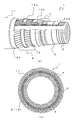
- FIG. 1 is a view showing the flexible tube 1
- FIG. 1 (a) is a perspective view
- FIG. 1 (b) is a cross-sectional view.
- the flexible tube 1 mainly comprises an interlock tube 3 which is a tube body, a resin layer 5, an internal pressure resistant layer 7, an axial force reinforcing layer 9, a protective layer 11, seat floor layers 13a, 13b, 13c, 13d, etc. Be done.
- the interlock tube 3 is made of stainless steel which is located in the innermost layer of the flexible tube 1 and has excellent buckling strength against external pressure and good corrosion resistance.
- the interlock tube 3 is formed by forming the tape into an S-shaped cross section and engaged with each other at the S-shaped portion to be coupled, and has flexibility.
- a resin layer 5 is provided on the outer peripheral side of the interlock pipe 3.
- the resin layer 5 shields the fluid flowing in the interlock tube 3.
- a polyamide resin or polyvinylidene fluoride (PVDF) that withstands high temperatures of 90 ° C. or more and is excellent in oil resistance can be used.
- the outer peripheral side of the interlock pipe 3 means that it is the outer side of the interlock pipe 3 in the cross section, and also includes having another layer structure between the interlock pipe 3 and the resin layer 5 .
- peripheral is simply referred to as “peripheral” in the positional relationship of each layer, it is needless to say that one having another layer structure between each layer is included as well.
- a seat bed 13 a is provided between the interlock pipe 3 and the resin layer 5 as needed.
- the seat floor layer 13 a is a layer for flattening the concavo-convex shape of the outer periphery of the interlock tube 3 substantially flat, and can be deformed following the flexibility of the interlock tube 3. That is, the seat floor layer 13a has a certain thickness, for example, like a non-woven fabric, and has a role as a cushion of the unevenness of the interlock tube 3 outer periphery.
- a seat bed it is provided as needed, and although the case where it has a seat bed is demonstrated in the following description, it is not necessarily a thing required. Therefore, in the following figures, illustration of a seat bed is omitted.
- the internal pressure resistant layer 7 is provided on the outer periphery of the resin layer 5.
- the internal pressure resistant layer 7 is a layer mainly for the internal pressure of the fluid flowing in the interlock pipe 3.
- the internal pressure resistant reinforcing layer 7 is formed by winding metal tapes having, for example, a C-shaped cross section or a Z-shaped cross section at short pitches so as to face each other and to overlap each other in the axial direction.
- the material of the internal pressure resistant layer 7 is set in consideration of the corrosion resistance to corrosive gas such as hydrogen sulfide gas which penetrates the resin layer 5 from the corrosive crude oil or the like flowing inside and enters the reinforcing layer.
- corrosive gas such as hydrogen sulfide gas which penetrates the resin layer 5 from the corrosive crude oil or the like flowing inside and enters the reinforcing layer.
- a low carbon steel having a carbon content of less than 0.5% may be subjected to a predetermined heat treatment to obtain a required corrosion resistance at the expense of a strength reduction of about 20%.
- the yield strength of the metal tape used for the internal pressure resistant layer 7 is about 1000 MPa.
- the axial force reinforcing layer 9 is provided on the outer periphery of the internal pressure resistant layer 7.
- the axial force reinforcing layer 9 is a reinforcing layer mainly for preventing the interlock tube 3 from being deformed (stretched) in the axial direction of the flexible tube 1.
- the axial force reinforcing layer 9 is formed by alternately winding two layers of reinforcing bars 15 described later at a long pitch. The axial force reinforcing layer 9 can be deformed following the flexibility of the interlock 3.
- the seat-bed layer 13b which is a resin tape made from polyethylene between the internal pressure-resistant reinforcement layer 7 and the axial force reinforcement layer 9 as needed.
- the seat-bed layer 13c which is a resin tape made from polyethylene between the two-layered reinforcement strip 15 wound helically in a reverse direction mutually.
- the resin tape used for the seat bed layer may use a resin material other than polyethylene as long as the strength and the corrosion resistance are equal.
- the seat floor layers 13 b and 13 c are for preventing the reinforcing members from being rubbed and worn when following the deformation of the flexible tube 1. Even in this case, the axial force reinforcing layer 9 is referred to as being provided on the outer peripheral side of the internal pressure resistant layer 7 regardless of the presence or absence of the seat floor layer.
- a seat bed 13 d is provided on the outer periphery of the axial force reinforcing layer 9 as necessary.
- the seat floor layer 13 d is a layer for flattening the concavo-convex shape of the outer periphery of the axial force reinforcing layer 9 substantially flat, and can be deformed following the flexibility of the interlock pipe 3.
- the seat bed layer 13d abbreviate
- a protective layer 11 is provided on the outer periphery of the seat floor layer 13d.
- the protective layer 11 is a layer for preventing, for example, seawater from invading the reinforcing layer.
- the protective layer 11 may be made of, for example, polyethylene resin or polyamide. As described above, each layer constituting the flexible tube 1 follows the bending deformation or the torsional deformation of the flexible tube 1 and has flexibility.
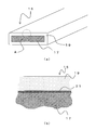
- FIG. 2 is a view showing a reinforcing bar 15, FIG. 2 (a) is a perspective view, and FIG. 2 (b) is an enlarged view of a portion A of FIG. 2 (a).
- the reinforcing strip 15 is composed of a metallic strip 17 and a resin layer 19 for covering the strip 17 or the like.
- a high carbon steel having a carbon content of 0.8% or more is used so that the flexible tube can withstand deep water of, for example, 2000 m or more, and has a yield strength of approximately 1700 MPa or more.
- Such a string 17 is known to decrease in strength to about 50% in the presence of corrosive gas. That is, it is necessary to obtain corrosion resistance to corrosive gas from corrosive crude oil flowing inside the flexible tube.
- the resin layer 19 which is a coating resin layer which covers the strip 17 shields such corrosive gas.
- the resin layer 19 is a portion made of resin that covers the entire circumference of the strip 17. If necessary, a sulfide trap material, which is fine particles, may be added to the resin layer 19.
- the resin has low permeability to water, chemicals, etc., has compatibility that can contain a large amount of sulfide trap material described later, and has physical properties necessary for being used for other fluid transport tubes. For example, polyethylene and polyamide resins can be used.
- the resin layer 19 is made to function as a sulfur barrier layer by shielding the hydrogen sulfide and the like by using the resin layer 19 containing a sulfide trap material or using a resin having a low permeability of sulfide. be able to.
- the width of the strip 17 is 10 to 20 mm, and the thickness is approximately 3 to 6 mm.
- the resin layer 19 is formed by extrusion-coating a resin with a thickness of 1 to 3 mm on the outer periphery of the strip 17.
- the sulfide trap material may be blended in the resin.
- sulfide trap material As a sulfide trap material, before and after reacting with sulfur in the fluid, it shows water-insoluble oil solubility, and the sulfide formed by the reaction with sulfur is very stable over a long period, and compatibility with the resin is It is sufficient that they can be dispersed uniformly and have a sufficiently high reaction rate with sulfur, for example, zinc, antimony, lead, iron, any metal of cadmium type, or metal compounds of these, or composites thereof You can use the body. In view of the ease of reaction with sulfur and the degree of stabilization of the reactant, Zn is desirable.
- sulfide trap material of the flexible tube In order to function efficiently as a sulfide trap material of the flexible tube 1, although depending on the kind of resin material and sulfide trap material, for example, about 5 to 60 parts by mass of sulfide trap material is added to the resin Preferably 10 to 40 parts by mass.
- the sulfide trap material is, for example, fine particles of about 1 ⁇ m, and is dispersed substantially uniformly in the resin material.
- the surface treatment layer 21 be formed on the surface of the strip 17.
- the surface treatment layer 21 desirably has corrosion resistance to hydrogen sulfide or the like, and for example, Sn, Zn, Cu, Ti plating or the like can be applied, and is, for example, about 10 ⁇ m.
- the surface treatment layer 21 is formed on the entire circumference of the strip 17. Zn, Ti, etc. are considered to be particularly preferable as the plating material.
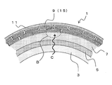
- FIG. 3 is a view showing a cross section of the flexible tube 1.
- a fluid such as oil is flowing in the interlock tube 3.
- the oil and the like may contain a corrosive gas (for example, a sulfide such as hydrogen sulfide).
- the resin layer 5 generally provided on the outer peripheral portion of the interlock pipe 3 is in contact with the fluid. That is, the sulfur content in the fluid contacts the resin layer 5.
- the sulfur component further passes through the resin layer 5 and intrudes into the internal pressure resistant reinforcing layer 7 and the axial force reinforcing layer 9 on the outer peripheral side of the resin layer 5 (arrow C in the figure). That is, the corrosive gas reaches the reinforcing layer.
- the internal pressure-resistant reinforcement layer 7 since the internal pressure-resistant reinforcement layer 7 has sufficient corrosion resistance, the strength reduction of the internal pressure-resistant reinforcement layer 7 etc. can be prevented.
- the strip 17 constituting the axial force reinforcing layer 9 is inferior in corrosion resistance by the corrosive gas, it is necessary to shield the corrosive gas from reaching the strip 17 by the resin layer 19.
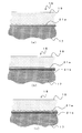
- FIG.4 (a) is the B section enlarged view of FIG. 3
- FIG.4 (b) is the D section enlarged view of Fig.4 (a).
- the corrosive gas having passed through the internal pressure resistant reinforcing layer 7 reaches the surface of the reinforcing bar 15 (in the direction of the arrow C in the figure).
- the resin layer 19 can prevent the permeation of the corrosive gas.
- the sulfide trap material prevents hydrogen sulfide from penetrating to the strip 17.
- the sulfur content S 2 ⁇ in the fluid and the sulfide trap material M 2+ react to form MS stable sulfide.
- the sulfide trap material does not have to be divalent, and may be another metal (and an intermetallic compound) as long as it can form a stable sulfide with S.
- the sulfur content contained in the fluid comes in contact with the resin layer 19
- the sulfide trap material in the resin layer reacts with the sulfur content to form a stable sulfide.
- the generated sulfide has a dense crystal structure, and as shown in FIG. 4B, the reaction layer 23 which is a sulfur shielding portion on the surface side of the resin layer 19 (the inner peripheral side of the flexible tube 1).
- the reaction layer 23 is composed of a stable and dense sulfide, the permeability (diffusion coefficient) of sulfur (sulfur and sulfide) in the reaction layer 23 becomes extremely small.
- the permeability (diffusion coefficient) of sulfur in the reaction layer 23 is extremely small as compared with the permeability (diffusion coefficient) of sulfur in the resin layer 19 at a portion other than the reaction layer 23. Therefore, when the reaction layer 23 having a certain thickness is formed, the growth of the reaction layer 23 in the thickness direction of the resin layer 19 (in the direction of the strip 17) is suppressed. That is, the reaction layer 23 is formed so as to spread in the axial direction of the resin layer 19 (axial direction of the reinforcing strip 15).
- the resin layer 19 reacts with sulfur in the fluid to form the reaction layer 23 which prevents permeation of the sulfur by itself, and the reaction layer 23 is formed in a layer on the surface of the resin layer 19. Therefore, the formation of the reaction layer 23 can reliably prevent permeation of the resin layer 19 of sulfur (that is, movement in the direction of the strip 17).
- the thickness of the reaction layer 23 is influenced by the types of the resin material and the sulfide trap material, and changes depending on the addition amount of the sulfide trap material even if the material is the same.
- the thickness of the reaction layer 23 becomes thinner if high density polyethylene having a smaller water permeability is used.
- the thickness of the reaction layer 23 becomes thicker if plasticized polyvinyl chloride having a higher water permeability is used.
- the thickness of the reaction layer 23 decreases as the addition amount of the sulfide trap material increases, and the thickness of the reaction layer 23 increases as the addition amount of the sulfide trap material decreases.
- the thickness of the reaction layer 23 varies depending on various conditions, for example, when about 40 parts by weight of a sulfide trap material is contained using plasticized polyvinyl chloride, diffusion of sulfur is surely prevented.
- the resin layer 19 is provided on the outer periphery of the reinforcing bar 15, the corrosive gas (or sulfur content) contained in the fluid flowing inside the flexible tube Can be prevented.
- the sulfide trap material contained in the resin layer 19 and the sulfide react with each other, whereby a stable and dense reaction layer 23 can be formed. For this reason, it is possible to prevent the corrosion of the strip 17 due to the sulfur contained in the fluid penetrating into the resin layer 19 and leaking to the surface of the strip 17.
- the reaction layer 23 Since the reaction layer 23 has a compact crystal structure, the diffusion coefficient of sulfur (including sulfide) is extremely small. Further, when the reaction layer 23 has a thickness of a certain degree or more, the growth in the thickness direction of the reaction layer 23 above is stopped, and when the reaction layer 23 is uniformly formed on the outer surface of the resin layer 19, The sulfur content and sulfides in the reaction layer 23 do not diffuse to the inner surface of the resin layer 19. Therefore, it is possible to prevent the sulfur content from leaking to the web 17 reliably over a long period of time.
- the resin layer 19 serves to keep the internal heat retention effect, so that it is possible to prevent the deterioration of the fluid fluidity.
- the surface treatment layer 21 is not limited to the example described above.
- FIG. 5 is a view showing another embodiment of the surface treatment layer.
- the surface treatment layer 21 a is, for example, a surface roughening treatment layer in which the blast treatment or the like is directly applied to the surface of the strip 17. According to the surface treatment layer 21a, the adhesion between the strip 17 and the resin layer 19 can be enhanced. In addition, the same effect can be exhibited also by the plating process in which the surface is roughened.
- a plurality of surface treatment layers may be formed.
- the surface treatment layer 21b which is a plated layer of Sn, Zn, Cu, or the like having high corrosion resistance is formed on the surface of the strip 17, and the Ti plating further enhances the adhesion to the resin layer on the surface
- the surface treatment layer 21a such as may also be formed.
- the surface treated layer 21b whose surface is roughened may be formed on the surface of the surface treated layer 21a having high corrosion resistance.
- the surface treatment layer 21b may be a plating treatment having a surface roughening effect, or may be a surface treatment of the surface treatment layer 21a.
- a primer to the strip 17 the adhesion to the coating resin can be improved.
- an acrylic reactive resin, an epoxy reactive resin, a urethane reactive resin, and a silane coupling agent are desirable.
- a sulfide trap material may be further blended in the resin layer 5.
- the resin layer 5 has flexibility and is in direct contact with the fluid, a material excellent in oil resistance is desirable.
- a material made of polyamide resin can be used.
- FIG. 6 is a view showing the function of the resin layer 5 having a sulfide trap material, as in FIG. 3 and the like. As shown to Fig.6 (a), the fluid which flows through the inside of the interlock pipe 3 contact
- the sulfur content reaching the resin layer 5 reacts with the sulfide trap material in the resin layer 5, and as shown in FIG. 6 (b), the reaction layer 23, which is a sulfur shielding portion, is formed on the inner peripheral portion of the resin layer 5.
- the reaction layer 23 is composed of a stable and dense sulfide, the diffusion coefficient of sulfur (sulfur and sulfide) in the reaction layer 23 becomes extremely small. Therefore, the resin layer 5 reacts with sulfur in the fluid to form the reaction layer 23 which prevents permeation of the sulfur by itself, and the formation of the reaction layer 23 ensures that the sulfur content to the outside of the resin layer 5. It is possible to prevent leakage.
- the migration of sulfur to the strip 17 can be more reliably prevented, and the migration of sulfur to the internal pressure resistant layer 7 is also prevented. Can.
- a slip layer may be provided between the resin layer 5 and the internal pressure resistant layer 7 as needed.
- a resin tape may be wound around the outer periphery of the resin layer 5 as the lubricating layer.
- the resin layer 5 becomes hard when a sulfide trap material is added, and therefore the internal pressure resistant reinforcing layer 7 is damaged when it is bent or the like by the contact at the interface with the internal pressure resistant reinforcing layer 7 which is a metal layer. It is because there is a possibility that a crack, abrasion, etc. may arise.
- a resin tape any slippage with the internal pressure resistant layer 7 is sufficient, and for example, a polyester tape can be used.
- FIG. 7 is a view showing the reinforcing strip 30, FIG. 7 (a) is a perspective view, and FIG. 7 (b) is an enlarged view of a portion F of FIG. 7 (a).
- the same reference numerals as in FIG. 3 are added to the configurations having the same function as the reinforcing strips 15, and the redundant description will be omitted.
- the reinforcing strip 30 is substantially the same as the reinforcing strip 15, but differs in that two resin layers are formed. As shown in FIG. 7 (b), in the reinforcing strip 15, resin layers 31, 33 are formed on the outer periphery of the strip 17. That is, the resin layer 31 on the inner layer side which is the covering resin layer is formed on the outer periphery of the strip 17, and the resin layer 33 on the outer layer side which is the outer layer side resin layer is formed on the outer periphery of the resin layer 31.
- the resin layer 31 is excellent in adhesion to the resin layer 33 with the strip 17.
- the adhesive strength between the resin layer 31 and the strip 17 is preferably such that the peel strength by a 180 ° peel test defined in ISO 8510-2 ASTM D 903 is 10 N / cm or more. By doing this, there is no peeling between the resin layer 31 and the strip 17 even in repeated bending of the flexible tube, and corrosion associated with peeling can be prevented.
- the adhesive resin which consists of a thermoplastic resin or a thermosetting resin can be used.
- an adhesive resin composed of a thermoplastic resin, an adhesive polyolefin resin, an adhesive fluorine resin, and a polyamide hot melt resin are desirable.
- maleic anhydride modified polyethylene, maleic anhydride modified polypropylene, and maleic anhydride modified ethylene / vinyl acetate copolymer are desirable.
- PVDF polyvinylidene fluoride
- ETFE maleic anhydride modified ethylene / tetrafluoroethylene copolymer
- polyamide based hot melt resin a dimer acid based polyamide is desirable.
- the resin layer 31 made of a thermoplastic resin may be produced by extruding and coating a resin on the reinforcing layer.
- an adhesive resin made of thermosetting resin epoxy resin, acrylic resin, unsaturated polyester resin, phenol resin, melamine resin, urea resin, silicone resin, urethane resin, polyimide resin Desirably, they all have excellent adhesion to the web.
- epoxy resins, urethane resins and polyimide resins are particularly desirable.
- the method for producing the resin layer 31 made of a thermosetting resin includes a spray application method on a reinforcing strip, a roll application method, a reactive injection molding method, an immersion method, and the like. For this purpose, a roll coating method is desirable.
- adhesive polyolefin resin or polyamide-based hot melt resin when the usage temperature environment of the resin layer 31 is 80 ° C. or less, and adhesive fluorocarbon resin or thermosetting resin when it is 80 ° C. or more. .
- the resin layer 33 is excellent in abrasion resistance to the resin layer 31. That is, even when the front is repeatedly applied to the flexible tube 1, the resin layer is abraded, and the function as a corrosive gas shielding layer is not impaired.
- the abrasion resistance of the resin layer 33 it is desirable that the abrasion loss by the Taber abrasion test specified in ISO 9352 ASTM D1044 be 30 mg / 1000 times or less. In this way, the abrasion of the resin layer can be suppressed even in repeated bending of the flexible tube, and corrosion associated with the abrasion can be prevented.
- the resin constituting the resin layer 33 is, for example, polyethylene resin, polypropylene resin, polyamide resin, fluorine resin, polyester resin, acrylic resin, styrene resin, polyvinyl chloride (PVC), modified resin Polyphenylene ether (modified PPE), polyphenylene sulfide (PPS) or the like can be used.
- polyethylene-based resin those excellent in abrasion resistance such as high density polyethylene (HDPE) and crosslinked polyethylene (XLPE) are desirable.
- HDPE high density polyethylene
- XLPE crosslinked polyethylene
- polypropylene resin those excellent in abrasion resistance such as homopolymers, block copolymers and random copolymers are desirable.
- polyamide resin those excellent in coating formability and abrasion resistance, such as polyamide 6 (PA 6), polyamide 11 (PA 11) and polyamide 12 (PA 12) are desirable.
- fluorine-based resin those excellent in coating formability and abrasion resistance, such as polyvinylidene fluoride (PVDF) and ethylene / tetrafluoroethylene copolymer (ETFE), are desirable.
- PVDF polyvinylidene fluoride
- ETFE ethylene / tetrafluoroethylene copolymer
- polyester resins include polyethylene terephthalate (PET) and polybutylene terephthalate (PBT).
- styrene resins include polystyrene (PS), acrylonitrile / styrene copolymer (AS), acrylonitrile / butadiene / styrene copolymer (ABS)
- AS acrylonitrile / styrene copolymer
- ABS acrylonitrile / butadiene / styrene copolymer
- acrylic resin polymethyl methacrylate (PMMA) can be used.
- the use temperature environment of the resin layer 33 is 80 ° C. or less, it is desirable to select polyethylene resin, polypropylene resin, polystyrene resin, polyvinyl chloride, polyamide resin, polyester resin, acrylic resin.
- the temperature is 80 ° C. or higher, it is desirable to select a fluorine-based resin, a modified polyphenylene ether, or a polyphenylene sulfide.
- the combination of the resin layer 31 on the inner layer side of the reinforcing layer and the resin layer 33 on the outer layer side has an operating temperature of 80 ° C. or higher It is desirable to select a resin.
- the combination whose use temperature environment is 80 degrees C or less can also be used as a resin layer of a reinforcement layer by the heat insulation effect.
- the resin layer 33 may be produced by extrusion coating on the reinforcing layer covered by the resin layer 31 or extrusion coating simultaneously with the resin layer 31.
- the resin layer 31 is required to have not only adhesiveness but also compression resistance.
- these properties are in a contradictory relationship, and it is difficult to solve with only the resin.
- the inorganic filler is preferably selected from glass fibers, carbon fibers, silica, talc, mica, clay, calcium carbonate, magnesium hydroxide, aluminum hydroxide, hydrotalcite and the like. Further, from the viewpoint of improving the compatibility with the resin, it is more preferable that the surface-treated with a silane coupling agent, an aluminum coupling agent, a titanate coupling agent, a fatty acid or the like.
- the amount of the inorganic filler added is preferably 10 to 100 parts by mass with respect to 100 parts by mass of the resin. If it is less than 10 parts by mass, the effect of the addition can not be obtained, and if it exceeds 100 parts by mass, it is not preferable because a decrease in adhesion and a decrease in tensile properties and impact properties are observed.
- the sulfide trap material which is the above-described fine particle, may be added to at least one of the resin layers 31 and 33.
- the resin layers 31 and 33 contain the sulfide trap material as described above, or the resin having low permeability of sulfide is used to shield hydrogen sulfide and the like, thereby shielding the resin layers 31 and 33 from sulfurization. It can function as a layer.
- the peel strength was evaluated by the 180 ° peel test specified in ISO 8510-2 ASTM D903.
- the acid modification is maleic anhydride modification.
- EVA is ethylene-vinyl acetate copolymer
- PE is polyethylene
- PVDF is polyvinylidene fluoride
- HDPE high density polyethylene
- PA11 is polyamide 11.
- the corrosion is the result of visually confirming the corrosion of the metal surface. Those with “corrosion” were identified as “presence” and those with no corrosion were designated “nothing". The judgment was made based on the presence or absence of corrosion. From the results, no corrosion was observed if the peel strength in the above test was 10 N / cm or more.
- Such resins were acid-modified PE, acid-modified EVA, and acid-modified PVDF.
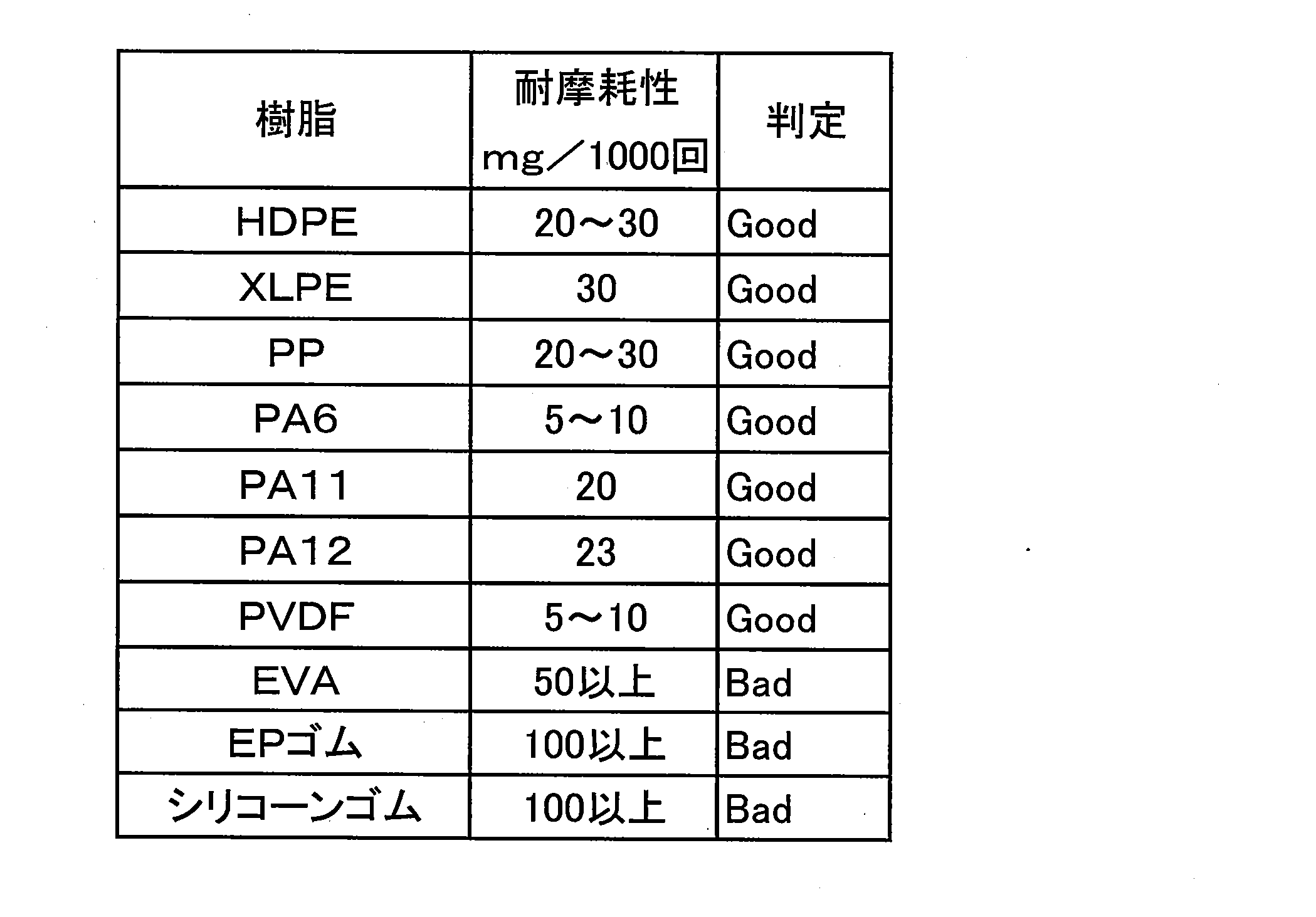
- the abrasion resistance was evaluated by the abrasion loss by the Taber abrasion test prescribed to ISO 9352 ASTMD1044.
- XLPE is cross-linked polyethylene
- PP is polypropylene
- PA6 is polyamide 6
- PA12 is polyamide 12
- EP rubber is ethylene propylene rubber.
- abrasion loss in the said test is 30 mg / 1000 times or less, it was judged that it was excellent in abrasion resistance. From the results, it was found that HDPE, XLPE, PP, PA6, PA11, PA12, and PVDF have high abrasion resistance.
Landscapes
- Engineering & Computer Science (AREA)
- General Engineering & Computer Science (AREA)
- Mechanical Engineering (AREA)
- Rigid Pipes And Flexible Pipes (AREA)
- Laminated Bodies (AREA)
Abstract
Description

3………インターロック管
5………樹脂層
7………耐内圧補強層
9………軸力補強層
11………保護層
13a、13b、13c、13d………座床層
15、30………補強条
17………条体
19………樹脂層
21、21a、21b………表面処理層
23………反応層
31、33………樹脂層
Claims (11)
- 可撓性を有する管体と、
前記管体の外周側に設けられた樹脂層と、
前記樹脂層の外周側に設けられた耐内圧補強層と、
前記耐内圧補強層の外周側に設けられた軸力補強層と、
前記軸力補強層の外周側に設けられた保護層と、
を少なくとも具備し、
前記軸力補強層は、
金属製の条体が被覆樹脂で被覆された補強条により形成されることを特徴とする流体輸送用可撓管。 - 前記被覆樹脂と前記条体との接着強度は、ISO8510-2 ASTMD903に規定される 180°ピール試験による剥離強度が10N/cm以上であることを特徴とする請求項1記載の流体輸送用可撓管。
- 前記被覆樹脂は、接着性ポリオレフィン系樹脂、接着性フッ素系樹脂、ポリアミド系ホットメルト樹脂、エポキシ系樹脂、アクリル系樹脂、不飽和ポリエステル系樹脂、フェノール系樹脂、メラミン系樹脂、ユリア系樹脂、シリコーン系樹脂、ウレタン系樹脂、ポリイミド系樹脂から選択される接着性樹脂からなることを特徴とする請求項1記載の流体輸送用可撓管。
- 前記被覆樹脂の外周には、外層側樹脂層がさらに設けられ、前記条体の外周の樹脂層は少なくとも2層構造であり、前記外層側樹脂層の耐摩耗性は、ISO9352 ASTMD1044に規定される テーバー摩耗試験による摩耗減量が、30mg/1000回 以下であること特徴とする請求項1記載の流体輸送用可撓管。
- 前記外層側樹脂層は、ポリエチレン系樹脂、ポリプロピレン系樹脂、ポリアミド系樹脂、フッ素系樹脂、ポリエステル系樹脂、アクリル系樹脂、スチレン系樹脂、ポリ塩化ビニル、変性ポリフェニレンエーテル、ポリフェニレンスルファイドから選択される樹脂であることを特徴とする請求項4記載の流体輸送用可撓管。
- 前記条体の表面には表面処理が施されることを特徴とする請求項1記載の流体輸送用可撓管。
- 前記条体の表面に表面粗化処理が施されるか、または、表面が粗化されるめっき処理が施されることを特徴とする請求項6記載の流体輸送用可撓管。
- 前記条体は、炭素含有量が0.8%以上の高炭素鋼であり、前記条体の表面にSn、Zn、Cu、Tiのいずれかを主成分とするメッキ処理層が形成されることを特徴とする請求項6記載の流体輸送用可撓管。
- 前記条体は、炭素含有量が0.8%以上の高炭素鋼であり、前記条体の表面に低炭素鋼またはアルミニウムをクラッドしたクラッド層が形成されることを特徴とする請求項6記載の流体輸送用可撓管。
- 前記被覆樹脂または前記外層側樹脂層の少なくとも一方が遮硫層として機能し、前記被覆樹脂または前記外層側樹脂層を構成する樹脂には、硫黄および/または硫化物と反応可能な硫化物トラップ材が配合され、前記硫化物トラップ材は、Zn、Sb、Pb、Fe、Cd系いずれかの金属、またはこれらの金属化合物、またはこれらの複合体のいずれかであることを特徴とする請求項4記載の流体輸送用可撓管。
- 前記被覆樹脂または前記外層側樹脂層を構成する樹脂の表層部には、使用状態において、前記管体内部を流れる流体に含まれる硫黄分と前記硫化物トラップ材とが反応することにより反応層が形成され、前記反応層における硫黄分の浸透度が、前記反応層以外の樹脂部における硫黄分の浸透度よりも小さいことを特徴とする請求項10記載の流体輸送用可撓管。
Priority Applications (3)
| Application Number | Priority Date | Filing Date | Title |
|---|---|---|---|
| BR112012021427A BR112012021427B8 (pt) | 2010-02-24 | 2011-02-23 | tubo flexível para transporte de fluido. |
| JP2012501818A JP5675768B2 (ja) | 2010-02-24 | 2011-02-23 | 流体輸送用可撓管 |
| US13/593,136 US8636037B2 (en) | 2010-02-24 | 2012-08-23 | Flexible tube for fluid transport |
Applications Claiming Priority (2)
| Application Number | Priority Date | Filing Date | Title |
|---|---|---|---|
| JPPCT/JP2010/052857 | 2010-02-24 | ||
| PCT/JP2010/052857 WO2011104830A1 (ja) | 2010-02-24 | 2010-02-24 | 流体輸送用可撓管 |
Related Parent Applications (1)
| Application Number | Title | Priority Date | Filing Date |
|---|---|---|---|
| PCT/JP2010/052857 Continuation WO2011104830A1 (ja) | 2010-02-24 | 2010-02-24 | 流体輸送用可撓管 |
Related Child Applications (1)
| Application Number | Title | Priority Date | Filing Date |
|---|---|---|---|
| US13/593,136 Continuation US8636037B2 (en) | 2010-02-24 | 2012-08-23 | Flexible tube for fluid transport |
Publications (1)
| Publication Number | Publication Date |
|---|---|
| WO2011105428A1 true WO2011105428A1 (ja) | 2011-09-01 |
Family
ID=44506277
Family Applications (2)
| Application Number | Title | Priority Date | Filing Date |
|---|---|---|---|
| PCT/JP2010/052857 Ceased WO2011104830A1 (ja) | 2010-02-24 | 2010-02-24 | 流体輸送用可撓管 |
| PCT/JP2011/053989 Ceased WO2011105428A1 (ja) | 2010-02-24 | 2011-02-23 | 流体輸送用可撓管 |
Family Applications Before (1)
| Application Number | Title | Priority Date | Filing Date |
|---|---|---|---|
| PCT/JP2010/052857 Ceased WO2011104830A1 (ja) | 2010-02-24 | 2010-02-24 | 流体輸送用可撓管 |
Country Status (4)
| Country | Link |
|---|---|
| US (1) | US8636037B2 (ja) |
| JP (1) | JPWO2011104830A1 (ja) |
| BR (2) | BR112012021432A2 (ja) |
| WO (2) | WO2011104830A1 (ja) |
Cited By (6)
| Publication number | Priority date | Publication date | Assignee | Title |
|---|---|---|---|---|
| WO2013128097A1 (fr) | 2012-03-01 | 2013-09-06 | Technip France | Conduite tubulaire flexible pour le transport d'hydrocarbures corrosifs |
| FR2993955A1 (fr) * | 2012-07-24 | 2014-01-31 | Technip France | Revetement metallique de fils d'armure en acier d'une conduite tubulaire flexible destinee au transport de fluide d'hydrocarbures |
| JP2014069509A (ja) * | 2012-09-28 | 2014-04-21 | Nippon Steel & Sumikin Chemical Co Ltd | 銅張積層体及び回路基板 |
| EP2733707A1 (de) * | 2012-11-14 | 2014-05-21 | Nexans | Langgestrecktes Gut mit einer Armierung |
| CN104089111A (zh) * | 2014-07-01 | 2014-10-08 | 山东冠通蓝海石油管材有限公司 | 混合材料增强型非粘结柔性管 |
| WO2016060010A1 (ja) * | 2014-10-17 | 2016-04-21 | ダイキン工業株式会社 | フレキシブル配管 |
Families Citing this family (7)
| Publication number | Priority date | Publication date | Assignee | Title |
|---|---|---|---|---|
| US9580586B2 (en) | 2012-12-12 | 2017-02-28 | Asahi Kasei Plastics North America, Inc. | Polypropylene compounds with enhanced haptics |
| ITMI20131165A1 (it) * | 2013-07-10 | 2015-01-11 | Prysmian Spa | Submarine flexible pipe |
| DE102015224173A1 (de) | 2015-12-03 | 2017-06-08 | Contitech Schlauch Gmbh | Umlageschlauch mit wenigstens einem Umlagenschutz |
| US20180023731A1 (en) * | 2016-07-19 | 2018-01-25 | Schlumberger Technology Corporation | Multi-layered coiled tubing designs with integrated electrical and fiber optic components |
| US20220403957A1 (en) * | 2019-11-25 | 2022-12-22 | National Oilwell Varco Denmark I/S | An unbonded flexible pipe |
| CN111853385B (zh) * | 2020-08-26 | 2024-07-19 | 江苏领嘉科技有限公司 | 一种钝齿环、高耐压压接连接金属管的管件及其加工方法 |
| US20220379578A1 (en) * | 2021-05-28 | 2022-12-01 | AGC Inc. | Fuel filler pipe |
Citations (1)
| Publication number | Priority date | Publication date | Assignee | Title |
|---|---|---|---|---|
| JPS54128022A (en) * | 1978-03-14 | 1979-10-04 | Dunlop Co Ltd | Oil transportation pipe |
Family Cites Families (21)
| Publication number | Priority date | Publication date | Assignee | Title |
|---|---|---|---|---|
| US2640501A (en) * | 1946-12-24 | 1953-06-02 | Int Standard Electric Corp | Tube and its manufacture |
| FR2203044B1 (ja) * | 1972-10-12 | 1976-11-19 | Battelle Memorial Institute | |
| US5176179A (en) * | 1983-12-22 | 1993-01-05 | Institut Francais Du Petrole | Flexible duct having no appreciable variation in length under the effect of an internal pressure |
| GB8420469D0 (en) | 1984-08-11 | 1984-09-12 | Dunlop Ltd | Hose |
| GB8421237D0 (en) | 1984-08-21 | 1984-09-26 | Dunlop Ltd | Hose(1) |
| JPS6353092U (ja) * | 1986-09-26 | 1988-04-09 | ||
| JPH01278339A (ja) * | 1988-04-30 | 1989-11-08 | Furukawa Electric Co Ltd:The | 可撓性サワー流体輸送管 |
| US5275209A (en) * | 1988-05-09 | 1994-01-04 | Institut Francais Du Petrole | Hose including an aluminum alloy |
| FR2647524B1 (fr) * | 1989-05-23 | 1991-10-31 | Inst Francais Du Petrole | Conduite flexible comportant un materiau composite a matrice en alliage d'aluminium et procede de fabrication dudit materiau |
| JPH0822447B2 (ja) * | 1991-03-18 | 1996-03-06 | 横浜ゴム株式会社 | 高圧ホース補強用金属線の製造方法及び高圧ホース |
| JP3228386B2 (ja) * | 1993-12-10 | 2001-11-12 | 石油公団 | 可撓性流体輸送管 |
| FR2756358B1 (fr) | 1996-11-22 | 1999-01-29 | Inst Francais Du Petrole | Gaine a permeabilite limitee et application aux conduites sous pression |
| FR2802608B1 (fr) * | 1999-12-17 | 2002-02-01 | Coflexip | Conduite flexible sous-marine de grande longueur a structure evolutive |
| DK200000241A (da) * | 2000-02-16 | 2001-01-18 | Nkt Flexibles Is | Fleksibel armeret rørledning, samt anvendelse af samme |
| FR2821144B1 (fr) * | 2001-02-22 | 2003-10-31 | Coflexip | Conduite flexible a film anti-retassure |
| FR2831238B1 (fr) * | 2001-10-24 | 2003-12-26 | Coflexip | Conduite tubulaire flexible pour le transport d'hydrocarbures a carcasse constituee d'un element allonge enroule agrafe par un feuillard |
| FR2834038B1 (fr) * | 2001-12-26 | 2004-05-28 | Coflexip | Conduite flexible aplatissable |
| FR2837899B1 (fr) * | 2002-03-28 | 2004-07-30 | Coflexip | Dispositif pour limiter le flambage lateral des nappes d'armures d'une conduite flexible |
| US6899140B2 (en) * | 2002-08-12 | 2005-05-31 | Wellstream International Limited | Flexible pipe and method of manufacturing same using metal reinforced tape |
| FR2904993B1 (fr) * | 2006-08-21 | 2008-10-17 | Technip France Sa | Conduite flexible a haute resistance a la compression axiale et methode de fabrication d une telle conduite. |
| FR2915552B1 (fr) * | 2007-04-27 | 2009-11-06 | Technip France | Conduite tubulaire flexible pour le transport d'hydrocarbures gazeux. |
-
2010
- 2010-02-24 WO PCT/JP2010/052857 patent/WO2011104830A1/ja not_active Ceased
- 2010-02-24 JP JP2012501569A patent/JPWO2011104830A1/ja active Pending
- 2010-02-24 BR BR112012021432A patent/BR112012021432A2/pt not_active IP Right Cessation
-
2011
- 2011-02-23 BR BR112012021427A patent/BR112012021427B8/pt active IP Right Grant
- 2011-02-23 WO PCT/JP2011/053989 patent/WO2011105428A1/ja not_active Ceased
-
2012
- 2012-08-23 US US13/593,136 patent/US8636037B2/en active Active
Patent Citations (1)
| Publication number | Priority date | Publication date | Assignee | Title |
|---|---|---|---|---|
| JPS54128022A (en) * | 1978-03-14 | 1979-10-04 | Dunlop Co Ltd | Oil transportation pipe |
Cited By (7)
| Publication number | Priority date | Publication date | Assignee | Title |
|---|---|---|---|---|
| WO2013128097A1 (fr) | 2012-03-01 | 2013-09-06 | Technip France | Conduite tubulaire flexible pour le transport d'hydrocarbures corrosifs |
| FR2993955A1 (fr) * | 2012-07-24 | 2014-01-31 | Technip France | Revetement metallique de fils d'armure en acier d'une conduite tubulaire flexible destinee au transport de fluide d'hydrocarbures |
| JP2014069509A (ja) * | 2012-09-28 | 2014-04-21 | Nippon Steel & Sumikin Chemical Co Ltd | 銅張積層体及び回路基板 |
| EP2733707A1 (de) * | 2012-11-14 | 2014-05-21 | Nexans | Langgestrecktes Gut mit einer Armierung |
| CN104089111A (zh) * | 2014-07-01 | 2014-10-08 | 山东冠通蓝海石油管材有限公司 | 混合材料增强型非粘结柔性管 |
| WO2016060010A1 (ja) * | 2014-10-17 | 2016-04-21 | ダイキン工業株式会社 | フレキシブル配管 |
| AU2015331572B2 (en) * | 2014-10-17 | 2017-11-23 | Daikin Industries, Ltd. | Flexible pipe |
Also Published As
| Publication number | Publication date |
|---|---|
| BR112012021432A2 (pt) | 2016-05-31 |
| BR112012021427A2 (pt) | 2016-05-24 |
| WO2011104830A1 (ja) | 2011-09-01 |
| BR112012021427B8 (pt) | 2020-06-16 |
| US20130037160A1 (en) | 2013-02-14 |
| BR112012021427B1 (pt) | 2020-05-26 |
| JPWO2011104830A1 (ja) | 2013-06-17 |
| US8636037B2 (en) | 2014-01-28 |
Similar Documents
| Publication | Publication Date | Title |
|---|---|---|
| WO2011105428A1 (ja) | 流体輸送用可撓管 | |
| US11162618B2 (en) | Flexible armoured pipe with a retaining layer of metal elongate strip | |
| US7976920B2 (en) | Flexible unbonded pipe and a method for producing such pipe | |
| AU2004282385B2 (en) | Flexible tubular line which is suitable, for example, for oil exploitation, comprising a PTFE coil | |
| GB2572120A (en) | Petroleum fluid-conveying flexible pipe comprising a barrier against diffusion | |
| JPH094768A (ja) | たわみホース及び連結ホース・アセンブリ | |
| WO2010071130A1 (ja) | 可撓性耐圧・耐油ホース | |
| EP3596257B1 (en) | Provision of electrical continuity and/or radial support | |
| CN108758118A (zh) | 一种深海柔性复合管 | |
| US11746935B2 (en) | Flexible pipe body and method | |
| CN208735117U (zh) | 柔性管复合抗压铠装层 | |
| JP5675768B2 (ja) | 流体輸送用可撓管 | |
| CN108825894A (zh) | 一种海洋用柔性管的骨架层和复合柔性管 | |
| US20140345741A1 (en) | Flexible pipe body and method of manufacture | |
| JP5255477B2 (ja) | 流体輸送用可撓管の製造方法 | |
| CN116293109A (zh) | 一种高强度抗拉柔性复合管道 | |
| EP3255327B1 (en) | Flexible pipe and related manufacturing method | |
| CN217583518U (zh) | 一种涤纶编织高压钢丝管 | |
| CN215334935U (zh) | 一种耐高温非粘结挠性复合管线 | |
| WO2024022616A2 (en) | Permeation-barrier and method of manufacture | |
| US11592125B2 (en) | Pipe body cathodic protection | |
| CN223924122U (zh) | 复合管道 | |
| JP5656971B2 (ja) | 流体輸送用可撓管および流体輸送用可撓管の製造方法 | |
| CN108825929A (zh) | 柔性管复合抗压铠装层 | |
| EP3060836A1 (en) | Flexible pipe body and method of producing same |
Legal Events
| Date | Code | Title | Description |
|---|---|---|---|
| 121 | Ep: the epo has been informed by wipo that ep was designated in this application |
Ref document number: 11747388 Country of ref document: EP Kind code of ref document: A1 |
|
| WWE | Wipo information: entry into national phase |
Ref document number: 2012501818 Country of ref document: JP |
|
| NENP | Non-entry into the national phase |
Ref country code: DE |
|
| 122 | Ep: pct application non-entry in european phase |
Ref document number: 11747388 Country of ref document: EP Kind code of ref document: A1 |
|
| REG | Reference to national code |
Ref country code: BR Ref legal event code: B01A Ref document number: 112012021427 Country of ref document: BR |
|
| ENP | Entry into the national phase |
Ref document number: 112012021427 Country of ref document: BR Kind code of ref document: A2 Effective date: 20120824 |