WO2011104916A1 - Method for producing hallow engine valve - Google Patents
Method for producing hallow engine valve Download PDFInfo
- Publication number
- WO2011104916A1 WO2011104916A1 PCT/JP2010/066479 JP2010066479W WO2011104916A1 WO 2011104916 A1 WO2011104916 A1 WO 2011104916A1 JP 2010066479 W JP2010066479 W JP 2010066479W WO 2011104916 A1 WO2011104916 A1 WO 2011104916A1
- Authority
- WO
- WIPO (PCT)
- Prior art keywords
- engine valve
- hollow
- hollow shaft
- shaft portion
- manufacturing
- Prior art date
Links
Images


Classifications
-
- F—MECHANICAL ENGINEERING; LIGHTING; HEATING; WEAPONS; BLASTING
- F01—MACHINES OR ENGINES IN GENERAL; ENGINE PLANTS IN GENERAL; STEAM ENGINES
- F01L—CYCLICALLY OPERATING VALVES FOR MACHINES OR ENGINES
- F01L3/00—Lift-valve, i.e. cut-off apparatus with closure members having at least a component of their opening and closing motion perpendicular to the closing faces; Parts or accessories thereof
-
- B—PERFORMING OPERATIONS; TRANSPORTING
- B21—MECHANICAL METAL-WORKING WITHOUT ESSENTIALLY REMOVING MATERIAL; PUNCHING METAL
- B21C—MANUFACTURE OF METAL SHEETS, WIRE, RODS, TUBES OR PROFILES, OTHERWISE THAN BY ROLLING; AUXILIARY OPERATIONS USED IN CONNECTION WITH METAL-WORKING WITHOUT ESSENTIALLY REMOVING MATERIAL
- B21C23/00—Extruding metal; Impact extrusion
- B21C23/02—Making uncoated products
- B21C23/18—Making uncoated products by impact extrusion
- B21C23/183—Making uncoated products by impact extrusion by forward extrusion
-
- B—PERFORMING OPERATIONS; TRANSPORTING
- B21—MECHANICAL METAL-WORKING WITHOUT ESSENTIALLY REMOVING MATERIAL; PUNCHING METAL
- B21K—MAKING FORGED OR PRESSED METAL PRODUCTS, e.g. HORSE-SHOES, RIVETS, BOLTS OR WHEELS
- B21K1/00—Making machine elements
- B21K1/20—Making machine elements valve parts
- B21K1/22—Making machine elements valve parts poppet valves, e.g. for internal-combustion engines
-
- B—PERFORMING OPERATIONS; TRANSPORTING
- B23—MACHINE TOOLS; METAL-WORKING NOT OTHERWISE PROVIDED FOR
- B23P—METAL-WORKING NOT OTHERWISE PROVIDED FOR; COMBINED OPERATIONS; UNIVERSAL MACHINE TOOLS
- B23P15/00—Making specific metal objects by operations not covered by a single other subclass or a group in this subclass
- B23P15/001—Making specific metal objects by operations not covered by a single other subclass or a group in this subclass valves or valve housings
- B23P15/002—Making specific metal objects by operations not covered by a single other subclass or a group in this subclass valves or valve housings poppet valves
-
- F—MECHANICAL ENGINEERING; LIGHTING; HEATING; WEAPONS; BLASTING
- F01—MACHINES OR ENGINES IN GENERAL; ENGINE PLANTS IN GENERAL; STEAM ENGINES
- F01L—CYCLICALLY OPERATING VALVES FOR MACHINES OR ENGINES
- F01L3/00—Lift-valve, i.e. cut-off apparatus with closure members having at least a component of their opening and closing motion perpendicular to the closing faces; Parts or accessories thereof
- F01L3/12—Cooling of valves
- F01L3/14—Cooling of valves by means of a liquid or solid coolant, e.g. sodium, in a closed chamber in a valve
-
- Y—GENERAL TAGGING OF NEW TECHNOLOGICAL DEVELOPMENTS; GENERAL TAGGING OF CROSS-SECTIONAL TECHNOLOGIES SPANNING OVER SEVERAL SECTIONS OF THE IPC; TECHNICAL SUBJECTS COVERED BY FORMER USPC CROSS-REFERENCE ART COLLECTIONS [XRACs] AND DIGESTS
- Y10—TECHNICAL SUBJECTS COVERED BY FORMER USPC
- Y10T—TECHNICAL SUBJECTS COVERED BY FORMER US CLASSIFICATION
- Y10T29/00—Metal working
- Y10T29/49—Method of mechanical manufacture
- Y10T29/49229—Prime mover or fluid pump making
- Y10T29/49298—Poppet or I.C. engine valve or valve seat making
- Y10T29/49307—Composite or hollow valve stem or head making
- Y10T29/49309—Composite or hollow valve stem or head making including forging
-
- Y—GENERAL TAGGING OF NEW TECHNOLOGICAL DEVELOPMENTS; GENERAL TAGGING OF CROSS-SECTIONAL TECHNOLOGIES SPANNING OVER SEVERAL SECTIONS OF THE IPC; TECHNICAL SUBJECTS COVERED BY FORMER USPC CROSS-REFERENCE ART COLLECTIONS [XRACs] AND DIGESTS
- Y10—TECHNICAL SUBJECTS COVERED BY FORMER USPC
- Y10T—TECHNICAL SUBJECTS COVERED BY FORMER US CLASSIFICATION
- Y10T29/00—Metal working
- Y10T29/49—Method of mechanical manufacture
- Y10T29/49405—Valve or choke making
Definitions
- the present invention relates to a method for manufacturing a hollow engine valve designed to improve strength and weight.
- the present invention solves the above-described problems, and provides a method for manufacturing a hollow engine valve capable of easily manufacturing a hollow engine valve designed to improve strength and weight. Objective.
- a method for manufacturing a hollow engine valve according to a first aspect of the present invention for solving the above problem is as follows.
- a plurality of hollow shaft portions having different hole shapes so as to reduce the outer diameter and inner diameter of the hollow shaft portion in a semi-finished product stepwise and to extend the length of the hollow shaft portion stepwise.
- the semi-finished product is heat treated so that it is below the specified hardness.
- the wall thickness between the hollow shaft portion and the valve head portion connected to the lower end of the hollow shaft portion is determined by the thickness of the hollow shaft portion by at least one of the forming holes whose hole length and hole diameter are adjusted. It is also characterized by thickening.
- a method for manufacturing a hollow engine valve according to a second invention for solving the above-described problems is as follows.
- the hole diameter of the valve umbrella molding part which molds the valve umbrella part in the molding hole is adjusted.
- a method for manufacturing a hollow engine valve according to a third aspect of the present invention for solving the above-described problem is as follows. After drawing by at least one of the forming holes, a refrigerant is injected into the hollow shaft portion, The opening of the hollow shaft portion is sealed after the final drawing by the forming hole.
- a method for manufacturing a hollow engine valve according to a fourth aspect of the present invention for solving the above problem is as follows. An opening of the hollow shaft portion is sealed after drawing by any one of the forming holes.
- a semi-finished product that has been heat-treated so as to have a predetermined hardness or less is formed with a hollow shaft portion and a valve head portion by means of a molded hole having a hole length and a hole diameter adjusted.
- the hollow engine valve can be easily manufactured so as to increase the strength and the weight by molding so that the wall thickness between the two is larger than the thickness of the hollow shaft portion.
- FIG. 1 is a longitudinal sectional view of a die conventionally provided in FIG. 1, and a longitudinal sectional view of a semi-finished product formed by the die. It is a longitudinal cross-sectional view of the hollow engine valve manufactured by the manufacturing method which concerns on this invention.
- a hollow engine valve 1 manufactured by the manufacturing method according to the present invention is used as an intake valve or an exhaust valve of an engine in a vehicle or the like, and is used as a metallic sodium N for refrigerant.
- the valve body 10 is formed by integrally forming a valve head portion 11 and a hollow shaft portion 12.
- a hollow hole 13 is formed in the valve body 10 across the valve head portion 11 and the hollow shaft portion 12. Yes.
- the maximum thickness of the neck portion 14 which is a connection portion between the valve head portion 11 and the hollow shaft portion 12 is formed to be thicker than the thickness of the hollow shaft portion 12.
- a shaft end sealing member 15 is joined to the base end (upper end) of the valve body 10 in a state in which metallic sodium N is injected.
- valve body 10 is manufactured by using a cold forging device 20 or the like which will be described later, and after the cold forging or after the cold forging, the metallic sodium N is injected into the hollow hole 13 and then the opening of the hollow hole 13 is opened.
- the shaft end sealing member 15 is joined to the base end so as to close the portion.
- metallic sodium N may not be enclosed.
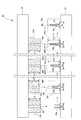
- the cold forging device 20 shown in FIG. 1 forms the valve body 10 by sequentially performing drawing (cold forging) processing on the semi-finished product 10a.
- a press bed 21 is provided at the lower part of the cold forging device 20, and a ram 22 is provided at the upper part so as to face the press bed 21, and the ram 22 is movable in the vertical direction. It is supported.
- cylindrical dies Di1, Di2 ′, Di (m ⁇ 1), Dim, Di (n ⁇ 1), and Din are provided in series along the conveying direction of the semi-finished product.
- the subscript m indicates the mth
- the subscript n indicates the nth (last)
- m ⁇ n where m and n are both positive integers of 3 or more.
- semi-finished products 10a, 10b, 10c (see FIG. 2 (a)), 10m, 10n and the valve body 10 can be transported and positioned on the top surface of the press bed 21 by transport means (not shown). .
- dice Di2 are demonstrated using FIG. 2 (a), (b).
- the dice Di2 ′ is for obtaining a semi-finished product 10c by drawing the semi-finished product 10b formed by the dice Di1. And in this semi-finished product 10c, it is shape
- the forming hole M2 ′ of the die Di2 ′ has a length L2 ′, which is used for finally forming the upper part of the valve head portion of the semi-finished product 10c.
- Molded part (valve molded part) Ma2 ′ and a molded part (shaft molded part) Mb2 ′ formed continuously on the upper part of the molded part Ma2 ′ and for molding the hollow shaft part of the semi-finished product 10c And have.
- the maximum inner diameter of the molding part Ma2 ′ is formed at D2 ′, and the inner diameter of the molding part Mb2 ′ is formed at d2.
- the length (height) of the semi-finished product 10c is formed into l2 ′, and the thickness of the hollow shaft portion is formed into t2.
- the maximum thickness of the neck portion is formed to t2 ′ thicker than the thickness t2.
- the die can be formed until the maximum thickness t2 ′ is approximately three times the thickness t2 (t2′ ⁇ 3t2).
- the forming hole M2 of the die Di2 is formed to have a length L2 (L2> L2 ′) longer than the length L2 ′, and the valve of the semi-finished product 10x A molding part Ma2 for finally molding the upper part of the umbrella part, and a molding part Mb2 formed continuously on the upper part of the molding part Ma2 and for molding the hollow shaft part of the semi-finished product 10x.
- the maximum inner diameter of the molding part Ma2 is formed at D2 (D2> D2 ′) larger than the maximum inner diameter D2 ′, and the inner diameter of the molding part Mb2 is formed at d2.
- the length (height) of the semi-finished product 10x is formed to be l2 (l2> l2 ′) longer than the length l2 ′, and the hollow shaft The thickness of the part and the maximum thickness of the neck are formed at t2.
- the semi-finished product 10c in which the maximum thickness t2 ′ of the neck portion is thicker than the thickness t2 of the hollow shaft portion can be formed.
- valve body 10 when manufacturing the valve body 10, first, a solid round bar material (not shown) is hot forged to form a semi-finished product 10a, and then the semi-finished product 10a has a predetermined hardness or less. It heat-processes so that it may become. Next, the semi-finished product 10a having a predetermined hardness or less is positioned at a position corresponding to the die Di1 on the press bed 21 of the cold forging device 20.
- the ram 22 is moved up and down, and the conveying means and the positioning operation of the conveying means are sequentially performed, and the throttling is performed n times by the dice Di1, Di2 ′, Di (m ⁇ 1), Dim, Di (n ⁇ 1), and Din. Process sequentially.
- the semi-finished product 10a is formed in the order of the semi-finished products 10b, 10c, 10m, and 10n, and accordingly, the outer diameter and inner diameter of each hollow shaft portion are reduced in stages.
- the length of each hollow shaft portion is extended stepwise, and the valve body 10 is finally formed.
- the semi-finished product 10a is heat-treated so as to have a predetermined hardness or less, so that the semi-finished product 10a and subsequent semi-finished products 10b, 10c, 10m, and 10n have low hardness. Accordingly, the thickness of the hollow shaft portion is likely to increase, and the length of the hollow shaft portion is difficult to extend.
- the tempered semi-finished product 10b is squeezed up by the forming hole M2 ′ of the die Di2 ′ adjusted to the length L2 ′ and the maximum inner diameter D2 ′, so that the semi-finished product 10c is It can be formed such that the maximum thickness t2 ′ is thicker than the thickness t2 of the hollow shaft portion.
- the hole shapes of these forming holes M (m-1), Mm, M (n-1), Mn Is not adjusted as compared with the conventional one, so that each neck portion is molded with the wall thickness being thick.
- the maximum wall thickness of the neck portion 14 is the hollow shaft portion 12. It is designed to be thicker than the wall thickness.
- the maximum thickness t2 ′ of the neck portion does not become a predetermined thickness with respect to the thickness t2 of the hollow shaft portion by one drawing processing
- the maximum thickness t2 The drawing process is performed a plurality of times until 'becomes a predetermined thickness.
- the molding holes M1, M2 ′, M (m ⁇ 1), Mm, M (n ⁇ 1), and Mn do not press the lower part of the valve head part in the semi-finished products 10a, 10b, 10c, 10m, and 10n.
- the maximum outer diameter of these valve head portions is held as Do.
- the shaft end sealing member 15 is joined to the base end so as to close the opening of the hollow hole 13, thereby completing the process.
- the hollow engine valve 1 as a product is manufactured.
- the valve head portion 11 vigorously contacts the valve seat and is heated to a high temperature, so that a particularly heavy load is applied to the neck portion 14. Since the maximum thickness of the neck portion 14 is increased to improve the strength of the neck portion 14, damage to the hollow engine valve 1 can be prevented. Moreover, since the thickness of the hollow shaft portion 12 that is difficult to apply a load is made as thin as possible, the weight of the hollow engine valve 1 can be reduced.
- the present invention can be applied to a hollow engine valve manufacturing apparatus for the purpose of manufacturing hollow engine valves having different shapes with one manufacturing apparatus by making the die exchangeable.
Abstract
Description
半完成品における中空軸部の外径寸法及び内径寸法を段階的に縮径させると共に、前記中空軸部の長さを段階的に延伸させるように、前記中空軸部を孔形状が異なった複数の成形孔に順次挿入して、その絞り加工を順次行うことにより、前記中空軸部を所定形状に成形するようにした中空エンジンバルブの製造方法において、
半完成品に対して、所定硬度以下となるように熱処理を施し、
孔長及び孔径を調整した少なくともいずれか1つの前記成形孔によって、前記中空軸部と当該中空軸部の下端に接続した弁傘部との間の肉厚を、前記中空軸部の肉厚よりも厚くする
ことを特徴とする。 A method for manufacturing a hollow engine valve according to a first aspect of the present invention for solving the above problem is as follows.
A plurality of hollow shaft portions having different hole shapes so as to reduce the outer diameter and inner diameter of the hollow shaft portion in a semi-finished product stepwise and to extend the length of the hollow shaft portion stepwise. In the method of manufacturing a hollow engine valve in which the hollow shaft portion is formed into a predetermined shape by sequentially inserting into the forming hole and sequentially performing the drawing process.
The semi-finished product is heat treated so that it is below the specified hardness,
The wall thickness between the hollow shaft portion and the valve head portion connected to the lower end of the hollow shaft portion is determined by the thickness of the hollow shaft portion by at least one of the forming holes whose hole length and hole diameter are adjusted. It is also characterized by thickening.
前記成形孔における前記弁傘部を成形する弁傘成形部の孔径を調整する
ことを特徴とする。 A method for manufacturing a hollow engine valve according to a second invention for solving the above-described problems is as follows.
The hole diameter of the valve umbrella molding part which molds the valve umbrella part in the molding hole is adjusted.
少なくともいずれか1つの前記成形孔による絞り加工後に、前記中空軸部内に冷媒を注入し、
最後の前記成形孔による絞り加工後に、前記中空軸部の開口部を封止する
ことを特徴とする。 A method for manufacturing a hollow engine valve according to a third aspect of the present invention for solving the above-described problem is as follows.
After drawing by at least one of the forming holes, a refrigerant is injected into the hollow shaft portion,
The opening of the hollow shaft portion is sealed after the final drawing by the forming hole.
いずれかの前記成形孔による絞り加工後に、前記中空軸部の開口部を封止する
ことを特徴とする。 A method for manufacturing a hollow engine valve according to a fourth aspect of the present invention for solving the above problem is as follows.
An opening of the hollow shaft portion is sealed after drawing by any one of the forming holes.
Claims (4)
- 半完成品における中空軸部の外径寸法及び内径寸法を段階的に縮径させると共に、前記中空軸部の長さを段階的に延伸させるように、前記中空軸部を孔形状が異なった複数の成形孔に順次挿入して、その絞り加工を順次行うことにより、前記中空軸部を所定形状に成形するようにした中空エンジンバルブの製造方法において、
半完成品に対して、所定硬度以下となるように熱処理を施し、
孔長及び孔径を調整した少なくともいずれか1つの前記成形孔によって、前記中空軸部と当該中空軸部の下端に接続した弁傘部との間の肉厚を、前記中空軸部の肉厚よりも厚くする
ことを特徴とする中空エンジンバルブの製造方法。 A plurality of hollow shaft portions having different hole shapes so as to reduce the outer diameter and inner diameter of the hollow shaft portion in a semi-finished product stepwise and to extend the length of the hollow shaft portion stepwise. In the method of manufacturing a hollow engine valve in which the hollow shaft portion is formed into a predetermined shape by sequentially inserting into the forming hole and sequentially performing the drawing process.
The semi-finished product is heat treated so that it is below the specified hardness,
The wall thickness between the hollow shaft portion and the valve head portion connected to the lower end of the hollow shaft portion is determined by the thickness of the hollow shaft portion by at least one of the forming holes whose hole length and hole diameter are adjusted. A method for manufacturing a hollow engine valve, characterized in that the thickness is also increased. - 請求項1に記載の中空エンジンバルブの製造方法において、
前記成形孔における前記弁傘部を成形する弁傘成形部の孔径を調整する
ことを特徴とする中空エンジンバルブの製造方法。 In the manufacturing method of the hollow engine valve of Claim 1,
A method for manufacturing a hollow engine valve, comprising adjusting a hole diameter of a valve head forming portion for forming the valve head portion in the forming hole. - 請求項1に記載の中空エンジンバルブの製造方法において、
少なくともいずれか1つの前記成形孔による絞り加工後に、前記中空軸部内に冷媒を注入し、
最後の前記成形孔による絞り加工後に、前記中空軸部の開口部を封止する
ことを特徴とする中空エンジンバルブの製造方法。 In the manufacturing method of the hollow engine valve of Claim 1,
After drawing by at least one of the forming holes, a refrigerant is injected into the hollow shaft portion,
A method for manufacturing a hollow engine valve, comprising: sealing an opening of the hollow shaft portion after the final drawing by the forming hole. - 請求項1に記載の中空エンジンバルブの製造方法において、
いずれかの前記成形孔による絞り加工後に、前記中空軸部の開口部を封止する
ことを特徴とする中空エンジンバルブの製造方法。 In the manufacturing method of the hollow engine valve of Claim 1,
A method for manufacturing a hollow engine valve, comprising: sealing an opening of the hollow shaft portion after drawing by any one of the forming holes.
Priority Applications (3)
| Application Number | Priority Date | Filing Date | Title |
|---|---|---|---|
| US13/504,877 US8881391B2 (en) | 2010-02-26 | 2010-09-24 | Method for producing hollow engine valve |
| CN201080048251.7A CN102597438B (en) | 2010-02-26 | 2010-09-24 | Method for producing hallow engine valve |
| EP10846579.0A EP2541002B1 (en) | 2010-02-26 | 2010-09-24 | Method for producing hollow engine valve |
Applications Claiming Priority (2)
| Application Number | Priority Date | Filing Date | Title |
|---|---|---|---|
| JP2010-041410 | 2010-02-26 | ||
| JP2010041410A JP5404472B2 (en) | 2010-02-26 | 2010-02-26 | Method for manufacturing hollow engine valve |
Publications (1)
| Publication Number | Publication Date |
|---|---|
| WO2011104916A1 true WO2011104916A1 (en) | 2011-09-01 |
Family
ID=44506355
Family Applications (1)
| Application Number | Title | Priority Date | Filing Date |
|---|---|---|---|
| PCT/JP2010/066479 WO2011104916A1 (en) | 2010-02-26 | 2010-09-24 | Method for producing hallow engine valve |
Country Status (5)
| Country | Link |
|---|---|
| US (1) | US8881391B2 (en) |
| EP (1) | EP2541002B1 (en) |
| JP (1) | JP5404472B2 (en) |
| CN (1) | CN102597438B (en) |
| WO (1) | WO2011104916A1 (en) |
Cited By (6)
| Publication number | Priority date | Publication date | Assignee | Title |
|---|---|---|---|---|
| JP2013155676A (en) * | 2012-01-30 | 2013-08-15 | Mitsubishi Heavy Ind Ltd | Method for producing hollow engine valve |
| US9283615B2 (en) * | 2011-12-27 | 2016-03-15 | Nittan Valve Co., Ltd. | Engine valve forging system |
| JPWO2014155665A1 (en) * | 2013-03-29 | 2017-02-16 | 日鍛バルブ株式会社 | Hollow poppet valve |
| WO2020100185A1 (en) | 2018-11-12 | 2020-05-22 | 日鍛バルブ株式会社 | Method for manufacturing engine poppet valve |
| US11300018B2 (en) | 2018-03-20 | 2022-04-12 | Nittan Valve Co., Ltd. | Hollow exhaust poppet valve |
| US11850690B2 (en) | 2020-03-30 | 2023-12-26 | Nittan Corporation | Method for manufacturing engine poppet valve |
Families Citing this family (14)
| Publication number | Priority date | Publication date | Assignee | Title |
|---|---|---|---|---|
| MX357066B (en) | 2012-10-02 | 2018-06-25 | Nittan Valva | Hollow poppet valve. |
| CN104981589B (en) | 2013-03-14 | 2017-12-26 | 日锻汽门株式会社 | Hollow lifting valve |
| JP6088641B2 (en) | 2013-04-11 | 2017-03-01 | 日鍛バルブ株式会社 | Hollow poppet valve |
| DE102013218488A1 (en) * | 2013-09-16 | 2015-03-19 | Mahle International Gmbh | Hollow valve, in particular for an internal combustion engine |
| US9683467B2 (en) * | 2014-12-10 | 2017-06-20 | General Electric Company | System and method of cooling valve with material in cavity |
| DE102014225618A1 (en) * | 2014-12-11 | 2016-06-16 | Mahle International Gmbh | Method for producing a hollow valve |
| DE102016200739A1 (en) * | 2016-01-20 | 2017-07-20 | Mahle International Gmbh | Metallic hollow valve for an internal combustion engine of a commercial vehicle |
| DE102017202585A1 (en) * | 2016-02-17 | 2017-08-17 | Mahle International Gmbh | Internal combustion engine with at least one cylinder and with at least two hollow-head valves |
| KR102169984B1 (en) * | 2016-09-02 | 2020-10-26 | 니탄 밸브 가부시키가이샤 | Cylinder head and engine |
| DE102017114509A1 (en) * | 2017-06-29 | 2019-01-03 | Federal-Mogul Valvetrain Gmbh | Cavity valve with optimized internal shaft geometry and method for its production |
| GB2567846A (en) | 2017-10-26 | 2019-05-01 | Eaton Srl | Poppet Valve |
| KR102259041B1 (en) * | 2018-10-26 | 2021-06-02 | 니탄 밸브 가부시키가이샤 | Manufacturing method of intermediate parts with boss parts of engine valves |
| DE102021115444A1 (en) | 2021-06-15 | 2022-12-15 | Bayerische Motoren Werke Aktiengesellschaft | Electrical energy store for a motor vehicle and method for producing such an electrical energy store |
| WO2023088581A1 (en) | 2021-11-16 | 2023-05-25 | Eaton Intelligent Power Limited | Hollow poppet valve and method of manufacturing |
Citations (2)
| Publication number | Priority date | Publication date | Assignee | Title |
|---|---|---|---|---|
| JP2009293465A (en) * | 2008-06-04 | 2009-12-17 | Aisan Ind Co Ltd | Method for manufacturing hollow valve |
| JP4390291B1 (en) | 2008-09-18 | 2009-12-24 | 株式会社 吉村カンパニー | Method for manufacturing valve head part of hollow engine valve and hollow engine valve |
Family Cites Families (16)
| Publication number | Priority date | Publication date | Assignee | Title |
|---|---|---|---|---|
| CH231293A (en) | 1938-05-17 | 1944-03-15 | Jeudi Gabriel | A method and machine for manufacturing a hollow head and stem valve, and a valve obtained by this method. |
| US2411734A (en) * | 1942-03-11 | 1946-11-26 | Thompson Prod Inc | Cold worked hollow stem valve |
| US2471937A (en) * | 1944-01-24 | 1949-05-31 | Thompson Prod Inc | Method of making hollow poppet valves |
| US2440461A (en) * | 1944-04-22 | 1948-04-27 | Eaton Mfg Co | Method of sealing the stem of hollow valves |
| US2731708A (en) * | 1952-10-31 | 1956-01-24 | Teves Kg Alfred | Process for manufacture of hollow poppet valves especially for internal-combustion engines |
| US3186209A (en) * | 1960-04-14 | 1965-06-01 | Nat Machinery Co | Method of cold forming an elongated hollow article |
| JP2670529B2 (en) * | 1989-06-14 | 1997-10-29 | フジオーゼックス株式会社 | Method and apparatus for injecting metallic sodium into hollow engine valve |
| DE3929534A1 (en) * | 1989-09-06 | 1991-03-28 | Daimler Benz Ag | METHOD FOR PRODUCING A VALVE |
| JPH03242408A (en) * | 1990-02-16 | 1991-10-29 | Aisan Ind Co Ltd | Manufacture of hollow engine-valve |
| US5413073A (en) * | 1993-04-01 | 1995-05-09 | Eaton Corporation | Ultra light engine valve |
| JPH10219377A (en) * | 1997-02-07 | 1998-08-18 | Daido Steel Co Ltd | Manufacture of high corrosion resistant valve for intake and exhaust valve for diesel engine and intake and exhaust valve |
| EP0911493A3 (en) * | 1997-10-21 | 2000-04-12 | Eaton Corporation | Improved tip structures for an ultra light engine valve |
| AT2881U1 (en) * | 1998-06-08 | 1999-06-25 | Plansee Ag | METHOD FOR PRODUCING A PAD VALVE FROM GAMMA-TIAL BASE ALLOYS |
| JP2006088197A (en) * | 2004-09-24 | 2006-04-06 | Aisan Ind Co Ltd | Manufacturing method for axial product with expanded head, manufacturing method for engine valve, and forging die used for manufacturing axial product with expanded head |
| JP4871293B2 (en) | 2005-11-15 | 2012-02-08 | 日鍛バルブ株式会社 | Hollow poppet valve with refrigerant and method for manufacturing the same |
| JP2008267202A (en) | 2007-04-18 | 2008-11-06 | Aisan Ind Co Ltd | Manufacturing method for hollow valve |
-
2010
- 2010-02-26 JP JP2010041410A patent/JP5404472B2/en not_active Expired - Fee Related
- 2010-09-24 EP EP10846579.0A patent/EP2541002B1/en not_active Not-in-force
- 2010-09-24 CN CN201080048251.7A patent/CN102597438B/en not_active Expired - Fee Related
- 2010-09-24 WO PCT/JP2010/066479 patent/WO2011104916A1/en active Application Filing
- 2010-09-24 US US13/504,877 patent/US8881391B2/en not_active Expired - Fee Related
Patent Citations (2)
| Publication number | Priority date | Publication date | Assignee | Title |
|---|---|---|---|---|
| JP2009293465A (en) * | 2008-06-04 | 2009-12-17 | Aisan Ind Co Ltd | Method for manufacturing hollow valve |
| JP4390291B1 (en) | 2008-09-18 | 2009-12-24 | 株式会社 吉村カンパニー | Method for manufacturing valve head part of hollow engine valve and hollow engine valve |
Non-Patent Citations (1)
| Title |
|---|
| See also references of EP2541002A4 * |
Cited By (10)
| Publication number | Priority date | Publication date | Assignee | Title |
|---|---|---|---|---|
| US9283615B2 (en) * | 2011-12-27 | 2016-03-15 | Nittan Valve Co., Ltd. | Engine valve forging system |
| JP2013155676A (en) * | 2012-01-30 | 2013-08-15 | Mitsubishi Heavy Ind Ltd | Method for producing hollow engine valve |
| US20140366373A1 (en) * | 2012-01-30 | 2014-12-18 | Mitsubishi Heavy Industries, Ltd. | Method for producing a hollow engine valve |
| US9427795B2 (en) * | 2012-01-30 | 2016-08-30 | Fuji Hollow Valve Inc. | Method for producing a hollow engine valve |
| JPWO2014155665A1 (en) * | 2013-03-29 | 2017-02-16 | 日鍛バルブ株式会社 | Hollow poppet valve |
| US11300018B2 (en) | 2018-03-20 | 2022-04-12 | Nittan Valve Co., Ltd. | Hollow exhaust poppet valve |
| WO2020100185A1 (en) | 2018-11-12 | 2020-05-22 | 日鍛バルブ株式会社 | Method for manufacturing engine poppet valve |
| KR20210089634A (en) | 2018-11-12 | 2021-07-16 | 니탄 밸브 가부시키가이샤 | Method of manufacturing the poppet valve of the engine |
| US11536167B2 (en) | 2018-11-12 | 2022-12-27 | Nittan Valve Co., Ltd. | Method for manufacturing engine poppet valve |
| US11850690B2 (en) | 2020-03-30 | 2023-12-26 | Nittan Corporation | Method for manufacturing engine poppet valve |
Also Published As
| Publication number | Publication date |
|---|---|
| CN102597438A (en) | 2012-07-18 |
| US20120255175A1 (en) | 2012-10-11 |
| EP2541002A4 (en) | 2013-10-16 |
| US8881391B2 (en) | 2014-11-11 |
| JP2011179328A (en) | 2011-09-15 |
| JP5404472B2 (en) | 2014-01-29 |
| EP2541002A1 (en) | 2013-01-02 |
| CN102597438B (en) | 2015-06-17 |
| EP2541002B1 (en) | 2014-11-26 |
Similar Documents
| Publication | Publication Date | Title |
|---|---|---|
| JP5404472B2 (en) | Method for manufacturing hollow engine valve | |
| JP5574752B2 (en) | Method for manufacturing hollow engine valve | |
| US9427795B2 (en) | Method for producing a hollow engine valve | |
| JP7051904B2 (en) | Hollow valve manufacturing method | |
| US10279440B2 (en) | Precision forming method of high-efficiency and near-net hollow valve blank of engine | |
| JP5062760B2 (en) | Bolt manufacturing method, bolt manufacturing apparatus, and bolt manufacturing mold | |
| JP4526097B1 (en) | Method for manufacturing valve head part of hollow engine valve, press device for valve head part of hollow engine valve, and hollow engine valve | |
| US9821365B2 (en) | Method for manufacturing a camshaft for an internal combustion engine by expanding a tubular element with a high pressure fluid and simultaneously compressing the tubular element axially | |
| KR101245228B1 (en) | manufacturing method of big size ball using a ball-valve | |
| JP5915937B2 (en) | Forging production method | |
| CN104769199A (en) | Method for producing a one-piece lock striker | |
| JP2013044287A (en) | Method and apparatus for manufacturing hollow engine valve | |
| KR20070052590A (en) | Die device of closed-die forging for crank throw pin part using insert die | |
| KR101183536B1 (en) | Forged product with hollow body and terminal flanges and manufacturing method thereof | |
| KR20060039819A (en) | Division metallic pattern for hot-forging and this use forging process | |
| KR101473948B1 (en) | Method for manufacturing flange structure | |
| JP5535741B2 (en) | Method for manufacturing valve head member of hollow engine valve | |
| JP2018118257A (en) | Hot-forging device and method for manufacturing engine valve using the same | |
| KR101009843B1 (en) | Manufacturing Method of Connecting Rod | |
| JP2004017107A (en) | Die and method for forming hollow shaft with projection | |
| JP2010137248A (en) | Manufacturing method of connecting rod, and connecting rod | |
| JP2012125790A (en) | Method for manufacturing hollow engine valve |
Legal Events
| Date | Code | Title | Description |
|---|---|---|---|
| WWE | Wipo information: entry into national phase |
Ref document number: 201080048251.7 Country of ref document: CN |
|
| 121 | Ep: the epo has been informed by wipo that ep was designated in this application |
Ref document number: 10846579 Country of ref document: EP Kind code of ref document: A1 |
|
| WWE | Wipo information: entry into national phase |
Ref document number: 2010846579 Country of ref document: EP |
|
| WWE | Wipo information: entry into national phase |
Ref document number: 1063/MUMNP/2012 Country of ref document: IN |
|
| WWE | Wipo information: entry into national phase |
Ref document number: 13504877 Country of ref document: US |
|
| NENP | Non-entry into the national phase |
Ref country code: DE |