WO2011102385A1 - 画像認識型細胞回収装置 - Google Patents
画像認識型細胞回収装置 Download PDFInfo
- Publication number
- WO2011102385A1 WO2011102385A1 PCT/JP2011/053281 JP2011053281W WO2011102385A1 WO 2011102385 A1 WO2011102385 A1 WO 2011102385A1 JP 2011053281 W JP2011053281 W JP 2011053281W WO 2011102385 A1 WO2011102385 A1 WO 2011102385A1
- Authority
- WO
- WIPO (PCT)
- Prior art keywords
- cell
- cells
- culture
- cultured
- cell culture
- Prior art date
- Legal status (The legal status is an assumption and is not a legal conclusion. Google has not performed a legal analysis and makes no representation as to the accuracy of the status listed.)
- Ceased
Links
Images






Classifications
-
- C—CHEMISTRY; METALLURGY
- C12—BIOCHEMISTRY; BEER; SPIRITS; WINE; VINEGAR; MICROBIOLOGY; ENZYMOLOGY; MUTATION OR GENETIC ENGINEERING
- C12N—MICROORGANISMS OR ENZYMES; COMPOSITIONS THEREOF; PROPAGATING, PRESERVING, OR MAINTAINING MICROORGANISMS; MUTATION OR GENETIC ENGINEERING; CULTURE MEDIA
- C12N11/00—Carrier-bound or immobilised enzymes; Carrier-bound or immobilised microbial cells; Preparation thereof
- C12N11/02—Enzymes or microbial cells immobilised on or in an organic carrier
- C12N11/10—Enzymes or microbial cells immobilised on or in an organic carrier the carrier being a carbohydrate
-
- C—CHEMISTRY; METALLURGY
- C12—BIOCHEMISTRY; BEER; SPIRITS; WINE; VINEGAR; MICROBIOLOGY; ENZYMOLOGY; MUTATION OR GENETIC ENGINEERING
- C12M—APPARATUS FOR ENZYMOLOGY OR MICROBIOLOGY; APPARATUS FOR CULTURING MICROORGANISMS FOR PRODUCING BIOMASS, FOR GROWING CELLS OR FOR OBTAINING FERMENTATION OR METABOLIC PRODUCTS, i.e. BIOREACTORS OR FERMENTERS
- C12M23/00—Constructional details, e.g. recesses, hinges
- C12M23/02—Form or structure of the vessel
- C12M23/10—Petri dish
-
- C—CHEMISTRY; METALLURGY
- C12—BIOCHEMISTRY; BEER; SPIRITS; WINE; VINEGAR; MICROBIOLOGY; ENZYMOLOGY; MUTATION OR GENETIC ENGINEERING
- C12M—APPARATUS FOR ENZYMOLOGY OR MICROBIOLOGY; APPARATUS FOR CULTURING MICROORGANISMS FOR PRODUCING BIOMASS, FOR GROWING CELLS OR FOR OBTAINING FERMENTATION OR METABOLIC PRODUCTS, i.e. BIOREACTORS OR FERMENTERS
- C12M25/00—Means for supporting, enclosing or fixing the microorganisms, e.g. immunocoatings
-
- C—CHEMISTRY; METALLURGY
- C12—BIOCHEMISTRY; BEER; SPIRITS; WINE; VINEGAR; MICROBIOLOGY; ENZYMOLOGY; MUTATION OR GENETIC ENGINEERING
- C12M—APPARATUS FOR ENZYMOLOGY OR MICROBIOLOGY; APPARATUS FOR CULTURING MICROORGANISMS FOR PRODUCING BIOMASS, FOR GROWING CELLS OR FOR OBTAINING FERMENTATION OR METABOLIC PRODUCTS, i.e. BIOREACTORS OR FERMENTERS
- C12M47/00—Means for after-treatment of the produced biomass or of the fermentation or metabolic products, e.g. storage of biomass
- C12M47/04—Cell isolation or sorting
Definitions
- the present invention relates to an apparatus and method for observing cultured cells and non-invasively detaching and re-culturing the target cells from the observation evaluation results.
- the cells collected from the tissue of multicellular organisms and cultured primarily contain various types of cells. In this way, identification of specific cells in tissues and culture media is an important technique in biological and medical analysis, and various methods have been developed. When there is almost no difference, it was necessary to identify the cells one by one based on information stained with fluorescent antibodies or visual information. With regard to this technique, for example, research and development has recently been progressing as a technique called Quantitative Imaging Cytometry (Non-patent Document 1: Harnett, M., “Laser scanning cytometry: understanding the immune system in situ” Nature Review Immunology, Vol. 7, pp.97897-904 (2007)) This imaging cytometry is a fusion of conventional optical microscope imaging methods and cytometry concepts.
- a reference value is set for a specific index such as cell shape and fluorescent labeling, and all cells in the tissue are measured and statistically processed. Even if a target cell is found by an observation technique, it is difficult to detach and re-culture only a specific cell.
- Patent Document 1 JP 2006-238707
- Patent Document 2 JP 2000-219708
- Patent Document 3 Japanese Patent Laid-Open No. 2000-219709
- Non-Patent Document 2 J R Soc Interface. 6 Suppl 3: S293-309 (2009).
- This substance has a hydrophobic property near 37 ° C., which is a temperature for culturing, and a hydrophilic property near 20 ° C.
- the present inventors have provided a noninvasive culture cell exfoliation apparatus and a noninvasive method for recovering specific cells in culture from a single cell unit in a noninvasive manner and without changing the temperature while maintaining an arbitrary culture temperature.
- the bottom of the culture dish is coated with a polymer gel that changes polymerization and depolymerization depending on the concentration of calcium ions in the solution in a thin layer, and cells are cultured in units of 1 cell. Place the chamber on the top surface, and after culturing the cells in 1-cell units in the chamber, let the chelating agent of calcium ion act on the chamber position of the cells you want to collect, so that the cultured cells are locally located in 1-cell units.
- a threshold value is set quantitatively by analyzing the cell state and observing the cell quantitatively. Depending on the situation, a technique for recovering cells is required.
- Embryonic stem cells and induced pluripotent stem cells (iPS cells) are usually adhered to a culture dish in order to induce differentiated cells such as nerve cells and cardiomyocytes. Therefore, it is necessary to exfoliate noninvasively in order to transplant differentiated cells on a culture dish.
- differentiated cells do not differentiate into only one type of cell, but differentiate into various types of cells. Therefore, it is necessary to collect noninvasively from one cell unit while confirming necessary cells.
- the temperature conditions for culturing cells vary depending on the type of cell, and depending on the cell, changing the temperature may change the state of the cell, so it can be cultured in any temperature environment. It is desirable that the cells can be recovered while maintaining this temperature even when the cells are recovered.
- the present invention provides the following cell culture device, method for manufacturing the cell culture device, noninvasive culture cell detachment method, selective culture cell recovery / reculture method, and culture cells.
- [1] a culture dish; A cell culture carrier layer containing a polymer gel formed on the surface of the culture dish and capable of being solated with a solubilizing agent; A cell culture apparatus comprising: [2] The cell culture device according to [1], further comprising an electrode or an array of a plurality of electrodes capable of measuring a cell potential between the surface of the culture dish and the cell carrier layer. [3] A cell potential measuring unit connected to the electrode and capable of measuring the cell potential; The cell culture device according to [2], further comprising a cell discrimination unit that discriminates cells to be collected by judging a change in cell type and cell state based on the cell potential measured by the cell potential measurement unit.
- the cell culture carrier layer according to any one of [1] to [3], wherein the cell culture carrier layer is formed of a thin film-like alginate gel layer containing calcium alginate or magnesium alginate mixed with a cell adhesion substrate.
- Cell culture equipment [5]
- the solubilizing agent is a chelating agent of calcium ions or magnesium ions, By applying the chelating agent in the vicinity of the cells to be collected, the portion of the cell culture carrier layer to which the chelating agent is applied is made into a sol, thereby peeling and collecting the target cultured cells locally in units of one cell.
- the cell culture device according to any one of [1] to [4], wherein [6]
- the cell culture device according to any one of [1] to [5] above, It is an agarose layer formed on the upper surface of the carrier layer, and a part of the agarose layer can be solated with the above-mentioned solubilizer and removed to enable cell culture in a single cell unit.
- An agarose layer comprising a microchamber having a volume to be extended and a microchannel extending from the microchamber,
- a cell culture apparatus comprising: [7] The cell culture device according to [6], wherein the part to which the solubilizing agent is applied is a microchamber containing the cells to be collected.
- a method for producing a cell culture device comprising: [12] before the step of forming the cell culture carrier layer, further comprising a step of arranging an electrode or an array of a plurality of electrodes capable of measuring a cell potential on the surface of the culture dish;
- the polymer gel is an alginate gel containing calcium alginate or magnesium alginate mixed with a cell adhesion substrate.
- the step of forming the microchamber and the microchannel By irradiating the agarose layer with focused infrared light having a wavelength of water absorption and changing the temperature to agarose in a gel state,
- the microchamber has a diameter of about 50 ⁇ m so that a single cell can just adhere, and the microchannel has a width of about 10 ⁇ m and a length of about 100 ⁇ m such that a nerve process can extend straight from the nerve cell.
- a step of preparing the cell culture device according to any one of [1] to [10] above, Culturing cells in the cell culture apparatus, A step of allowing a solubilizer to act on a portion of a cell culture carrier layer in the vicinity of a cell to be collected, and a step of locally peeling and collecting the cultured cells in units of one cell A non-invasive method for detaching cultured cells.
- the state of the cells is optically or electrically observed, and the culture carrier layer is solated by adding a solubilizer in one chamber unit based on the observation result,
- the method according to [16] above which comprises collecting the target cells that have floated as a result of the lower culture carrier layer being made into a sol.
- an alginate gel layer containing calcium alginate or magnesium alginate gel formed in a thin film and mixed with a cell adhesion substrate is used as the cell culture carrier layer of the cell culture device.
- a hollow microneedle with an inner diameter that allows several cells to be recovered simultaneously filled with a culture solution containing ethylenediaminetetraacetic acid sodium salt (EDTA ⁇ 2Na) as a solubilizing agent inside the needle, After a few days of culture, the above-mentioned culture solution containing EDTA ⁇ 2Na is locally sprayed on the cells that adhere and have phenotypes revealed by optical or electrical measurement techniques.
- Solubilize calcium alginate or magnesium alginate gel that is a scaffold for cultured cells The method according to [16] or [17] above, comprising non-invasively exfoliating a target cell. [19] The method according to [18] above, comprising collecting, with a microneedle, cells suspended by the alginate gel layer serving as a scaffold for the cultured cells formed into a sol.
- a stage unit including an XY stage on which a cell culture dish provided with a cell culture carrier layer including a polymer gel that is formed on the surface of the culture dish and can be solated with a solubilizing agent;
- An optical microscope system for microscopic observation of the cultured cells in the cell culture dish,
- An imaging unit optically connected to the optical microscope system and including an optical camera that captures an optical image from the optical microscope;
- a display unit including a display for displaying an image captured by the imaging unit;
- a first micropipette part including a micropipette for discharging a solubilizing agent that discharges a solubilizing agent capable of solating the polymer gel;
- a second micropipette part including a micropipette for cell recovery for recovering cultured cells that have become detachable due to the polymer gel being sol;
- a recording unit for recording the captured image;
- a control / analysis unit that controls the operation of each unit and analyzes the captured image;
- Target cells are selectively collected based on the optical image of the cells cultured on the surface of the culture dish imaged by the imaging unit and the cell potential of the cells measured by the cell potential measurement system.
- the cultured cell separation and recovery system according to [23] or [24], which can be performed.
- the polymer gel is an alginate gel containing calcium alginate or magnesium alginate gel, and the solubilizing agent is a chelating agent of calcium ions or magnesium ions.
- the system according to [19] further comprising a culture dish for re-culture for re-culturing the cells collected with the micropipette for cell collection.
- a method for separating cells using the cultured cell separation and recovery system according to any one of [23] to [27], Quantifying the cultured cell image data acquired by the imaging unit according to desired parameters, and selecting the cultured cells based on a predetermined threshold; Dissolve the cell culture carrier layer by discharging a solubilizer using a first micropipette part in the vicinity of the sorted cell or cell group, and the sorted cell or cell group that has become detachable is the second micropipette.
- a cell separation method comprising: [29] Presence / absence and / or expression of each ion channel based on the release time after depolarization of each ion channel expressed on the cell surface based on cell potential data of the cultured cells acquired by the measuring unit that measures the cell potential Quantifying as a parameter the approximate amount and / or the presence and / or degree of transmission of depolarization stimuli between cells to be joined, and sorting the cultured cells based on a predetermined threshold, The cell separation method according to [28], further comprising: [30] The method according to [28] or [29] above, further comprising the step of re-culturing the collected cells. [31] The method described in [28] or [30] above, wherein the parameter is cell shape, cell cycle, stem cell colony analysis, or cell differentiation degree.
- a step of preparing a culture dish on which a cell culture carrier layer containing a polymer gel that can be solated by a solating agent is formed Applying the polymer gel denaturing agent to a template having a desired pattern, stamping the cell culture carrier layer surface with the template, and placing the denaturant on the cell culture carrier layer surface; The manufacturing method of the culture dish for noninvasive peeling including this.
- the production method according to [32] wherein the polymer gel is an alginate gel containing calcium alginate or magnesium alginate gel, and the modifier is polylysine.
- the production method according to [32] wherein nerve cells are used as the cultured cells.
- the manufacturing method according to [32], wherein the pattern of the mold is a tile pattern.
- a non-invasive exfoliation culture dish produced by the production method according to any one of [32] to [35].
- a method for noninvasively collecting cells in culture A step of culturing cells using the noninvasive exfoliation culture dish described in [36] above, A step of adding a solubilizing agent to the culture dish, and a step of detaching cultured cells from the cell culture carrier layer solated by the solubilizing agent, Including a method.
- cultured cells to be reused can be efficiently selected and collected.
- the present invention provides a cell culture device.
- the cell culture apparatus includes a culture dish (culture plate) and a cell culture carrier layer containing a polymer gel that is formed on the surface of the culture dish and can be solated by a solubilizing agent. .
- an agarose layer formed on the upper surface of the carrier layer is further provided.
- a part of the agarose layer is removed to form a microchamber having a volume that enables cell culture in a single cell unit and a microchannel extending from the microchamber.
- the “polymer gel” used in the present invention is typically a polymer gel that forms a sol by chelating a metal ion with a chelating agent of a metal ion such as EDTA or EGTA, that is, for example, calcium alginate.
- a metal ion such as EDTA or EGTA
- examples include, but are not limited to, gels, alginic acid gels such as magnesium alginate gel.
- the insolubilized (or modified) alginate gel includes, for example, an alginate polylysine gel.
- the “solating agent” of alginic acid gel includes, for example, calcium ion chelating agents (eg, EDTA ⁇ 2Na, EGTA, NTA (Nitrilo Triacetic Acid), citric acid, phytic acid, etc.) (particularly, , Calcium alginate gel), magnesium ion chelating agents (example: EDTA ⁇ 2Na) (particularly in the case of magnesium alginate gel), but not limited thereto.
- calcium ion chelating agents eg, EDTA ⁇ 2Na, EGTA, NTA (Nitrilo Triacetic Acid), citric acid, phytic acid, etc.
- “Insolubilizers” or “denaturing agents” of polymer gels or alginic acid gels include, for example, cationic reagents such as polylysine (poly-L-lysine: PLL), and acidic reagents (reagents that are stronger than alginic acid). However, it is not limited to these.
- the cell culture device of the present invention can be prepared, for example, by preparing a thin layer of calcium alginate gel on a culture dish by causing a calcium chloride solution to act on sodium alginate mixed with a cell-adhesive substrate. it can.
- a thin film of agarose gel is further laminated and adhered on the calcium alginate gel layer, and a part of the agarose layer is locally formed into a shape suitable for cell culture.
- the calcium alginate mixed with the cell adhesion substrate is exposed to construct a microchamber and a microchannel extending therefrom. Therefore, this invention also provides the manufacturing method of a cell culture apparatus in one Embodiment.
- a chamber for arranging cells is constructed by locally dissolving the agarose layer.
- the agarose layer is irradiated with focused infrared light having a certain wavelength of water absorption to change the gel state of agarose into a sol state, and optically confirms the position of the agarose layer.
- a chamber can be constructed by specifying the agarose region to be used.
- the present invention also provides a non-invasive method for detaching cultured cells.
- the present invention creates a population cell group in which cells are dispersed and cultured using only an alginate layer (no agarose gel layer) coated on a culture dish, and the cells are detached.
- an alginate layer no agarose gel layer
- the present invention provides an agarose gel layer on an alginate layer, and a part of the agarose gel layer is removed to form a microchamber and a microchannel, and a nerve is formed in the microchamber and the microchannel.
- a method for non-invasively detaching and reusing cultured nerve cells in which a neural network is artificially created by culturing cells while maintaining the shape of the network.
- a part of an agarose layer on an alginate sheet formed on the surface of a culture dish is dissolved with infrared focused light to form a certain shaped chamber and channel
- a non-invasive exfoliation method after clarifying the degree of differentiation of nerve cells by culturing the nerve cells.
- a small-scale chamber is created by dissolving agarose (hereinafter referred to as a microchamber) with a diameter of about 50 ⁇ m to which one cell can just adhere, and as a modification, the nerve process can be extended in a straight line.
- a microchannel Create a groove (hereinafter referred to as a microchannel) with a width of approximately 10 ⁇ m and a length of approximately 100 ⁇ m so as to be connected to the microchamber (hereinafter referred to as patterning), place cells on the patterned area, and continue to culture for a while. Since the neurites extend along the axis, a selective peeling method is provided by confirming and peeling the neurite.
- the cells are cultured in units of one cell and observed by means of optical or electrical observation of the state of the cells.
- the alginate gel (eg, calcium alginate gel) layer was solated by adding a solution containing a solubilizer (eg, a drug capable of chelating calcium ions) in chamber units, and the lower layer was solated
- the cultured cells can be isolated non-invasively by collecting the target cells suspended by the above.
- the bottom surface of a culture dish is coated with a polymer gel that changes in polymerization / depolymerization depending on the concentration of calcium ions in the solution in a thin layer, and a chamber for culturing cells in units of one cell Cells can be cultured in cell units, and calcium ion chelating agents (eg, EDTA-2Na, EGTA, NTA® (Nitrilo® Triacetic® Acid), citric acid, phytic acid, etc.) are to be recovered.
- calcium ion chelating agents eg, EDTA-2Na, EGTA, NTA® (Nitrilo® Triacetic® Acid), citric acid, phytic acid, etc.
- a hollow microneedle having an inner diameter sufficient to collect several cells from one cell at a time is prepared, and the inside of the needle is, for example, a culture solution containing sodium ethylenediaminetetraacetate (EDTA ⁇ 2Na).
- EDTA ⁇ 2Na sodium ethylenediaminetetraacetate
- cells suspended by the formation of calcium alginate which is a scaffold for cultured cells, can be collected with a microneedle and transferred to another cell culture dish.
- FIG. 1 is a diagram conceptually showing an example of the configuration of the cell culture device of the present invention used for non-invasive detachment of cultured cells.
- FIG. 1A shows an example of a cell culture device in which an alginate gel (eg, calcium alginate gel or magnesium alginate gel) in which a thin cell adhesion substrate 201 is mixed in a culture dish is prepared on the culture dish 101.
- FIG. 1B shows an example of a cell culture apparatus comprising a micropatterned culture dish in which an agarose sheet 301 is coated on a cell adhesion substrate 201 laid on a culture dish 101, and agarose is partially dissolved by local heating. Show.
- the cell adhesion substrate 201 can be changed depending on the cells to be cultured.
- cell adhesion substrates examples include cationic reagents such as polylysine and polyethyleneimine, collagen, vitronectin, laminin, fibronectin, and lectin.
- cationic reagents such as polylysine and polyethyleneimine, collagen, vitronectin, laminin, fibronectin, and lectin.
- a cationic reagent such as polylysine (poly-L-lysine: PLL) or an acidic reagent (a reagent with a stronger acid than alginic acid) is mixed in the alginic acid gel, it will not be solated by a chelating agent such as EDTA ⁇ 2Na.
- cells can be cultured on an alginate sheet for each cell. Take measures to peel off with a chelating agent (see FIGS. 7 to 9). Further, as other adhesion substrate, it is preferable to mix a reagent that hardly denatures alginate gel (eg, neutralized collagen type IV, vitronectin, laminin, fibronectin, lectin, etc.).
- a reagent that hardly denatures alginate gel eg, neutralized collagen type IV, vitronectin, laminin, fibronectin, lectin, etc.
- 201 may be alginic acid whose adhesion ability is increased by cross-linking a protein composed of arginine-glycine-aspartic acid, which is a cell binding domain, with alginic acid.
- the microchamber 302 and the microchannel 303 are manufactured by an apparatus for performing agarose processing shown in FIG.
- FIG. 2 is a schematic diagram of the overall configuration of the agarose processing apparatus when processing the agarose layer of the cell culture apparatus of the present invention.
- the agarose processing apparatus includes a 1480 nm Raman fiber laser generator 501, a laser shutter 702, a dichroic mirror 703, an objective lens 701, a mirror 706, a CCD camera 704, and an xy stage 601.
- the Raman fiber laser 502 generated from the Raman fiber laser generator 501 is reflected by the dichroic mirror 703 and focused by the objective lens 701.
- the agarose on the noninvasive peeling dish 401 is locally heated by the focused 1480 nm laser focused light 503 to create the microchamber 302 and the microchannel 303.
- the micro chamber 302 and the micro channel 303 are created by changing the laser output of the Raman fiber laser generator 501 and the magnification of the objective lens 701 and the shutter speed of the shutter 702, and the output of the laser focused light 503, the focal radius, and the irradiation time. This can be done by changing the shape and can be processed into various shapes.
- the microchannel 303 can be created by moving the xy stage 601 while continuing to irradiate the irradiation light 503. Such processing is performed while observing the photographed image 705 using the objective lens 701, the mirror 706, and the CCD camera 704. Processing can be automatically performed by automatically controlling the shutter 702 and the xy stage 601 with a computer.
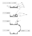
- FIG. 3 is a schematic diagram showing a series of steps from cell culture on a non-invasive exfoliation culture dish to cell exfoliation, cell recovery, and re-culture over time.
- step 1 cell culture is started on the noninvasive peeling culture dish 401.
- the cells do not adhere on the agarose sheet 301 but adhere on the alginate sheet 201 of the cell adhesion substrate.
- step 2 the alginate sheet 201 of the cell adhesion substrate under the cells 801 is locally applied by spraying the EDTA-containing medium 1001 near the target cells with the microneedles 901. To sol. Thereby, the cells that have adhered and differentiated are non-invasively detached.
- step 3 the microneedle 901 used in step 2 is collected.
- the cells collected in step 3 are re-cultured by transferring them to another culture dish in step 4.
- the re-culture in step 4 other than the culture dish, it may be transplanted as it is to a living tissue.
- FIG. 4 is a diagram showing a result obtained by actually performing the process in FIG. 3 and observing the process.
- Fig. 4 shows the state of exfoliation and re-cultivation after dispersion culture in a non-invasive culture dish without an agarose gel layer in the upper stage (A1, A2), and culture with an agarose layer in the lower stage (B1, B2).
- A1, A2 the state of exfoliation and re-cultivation after dispersion culture in a non-invasive culture dish without an agarose gel layer in the upper stage
- B1, B2 This is a time series photograph of the state of non-invasive detachment, recovery and re-culture of cells cultured on a microchamber / microchannel after agarose processing in a dish. In the re-culture, a state of adhesion after 30 minutes from peeling is observed.
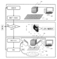
- FIG. 5 shows a schematic diagram of an apparatus system that automates the process of separating and collecting only characteristic cells after analyzing the physiological properties of cultured cells.
- a non-invasive cell detachment culture dish 401 and a cell recovery culture dish 402 are prepared on the XY stage 601, and a physiological characteristic extraction of a cell population is performed using a CCD camera 704 and a control personal computer 2001, and then an alginate solution.
- the apparatus system of the present invention includes an optical microscope system for observing cells in the culture dish on the XY stage 601, and the CCD camera 704 is optically connected to the optical microscope system. It is connected.
- the optical microscope that can be used in the present invention include, but are not limited to, a phase contrast microscope, a differential interference microscope, a bright field microscope, a dark field microscope, and a scanning optical microscope.
- the collected cells are re-cultured in the cell collection culture dish 402.
- the control computer 2001 automatically performs cell image analysis by CCD, XY stage control, alginate solution discharge control, and cell recovery necessary for this operation.
- Cell shape, cell cycle, cell colony analysis (cell color reagent such as Hoechst reagent, characteristics of spatial distribution of intracellular molecules by scanning confocal Raman spectroscopy, cell colony size, or cell colony size Etc.), or the ratio of cell nucleus to cell size, the degree of cell differentiation by analyzing the amount and distribution of cytoplasmic organelles, etc., can be used for the separation and collection of cells.
- FIG. 6 shows the procedure of cell sorting by image analysis of cultured cells cultured on a culture dish.
- the cultured cells on the non-invasive peeling culture dish are analyzed by the CCD camera 704 and the control personal computer 2001.
- parameters for confirming cell characteristics eg, cell shape, cell cycle, cell colony shape and size analysis over time, degree of cell differentiation
- the region (or threshold) having the characteristics to be collected is controlled.
- the cells having the set characteristics are peeled off by the micropipette 902 for discharging the alginic acid solution, recovered by the micropipette 903 for cell recovery, and transferred to the culture dish 402 for cell recovery.
- the micropipette part including the micropipette 902 for discharging the solution may further include a solution tank for holding the solution, means for feeding the solution (eg, pump, syringe, motor, etc.) and the like.
- the micropipette part including the cell recovery micropipette 903 may further include means for aspirating cells (eg, pump, syringe, motor, etc.).
- FIG. 7 shows the process of producing a non-invasive exfoliation culture dish for exfoliating nerve cells.
- a template for stamping the PLL on an alginate gel eg, calcium alginate gel, magnesium alginate gel
- PDMA polydimethylsiloxane
- FIG. 8A shows a part of the shape of PLL micro-printed on an alginate sheet.
- FIG. 8B is a diagram when primary hippocampal neurons are cultured on an alginate sheet on which PLL is microcontact-printed.
- a minute area where about one cell can adhere can be appropriately produced (for example, in a tile shape) as an insolubilized region, and as a result, while cells are cultured on an alginate sheet, the cells can be detached with a chelating agent.
- FIG. 9 shows a state in which nerve cells are cultured using a non-invasive peeling culture dish as shown in FIGS. 7 and 8 and then the cultured nerve cells are peeled non-invasively for each cell. It is the figure typically shown in contrast with. 9A shows a case where PLL is applied to the entire surface of the alginate gel layer on the culture dish, and FIG. 9B shows a case where PLL is applied in a tile shape. As shown in FIG. 9A, when the entire culture carrier is an insolubilized alginate gel 4001, even if the solubilizing agent 1002 is acted using the micropipette 904, it is non-invasively removed from the culture dish for each cell. It is difficult to peel off. On the other hand, as shown in FIG.
- the joint portion of the tile pattern is the alginate gel 4002 that is not insolubilized.
- 1002 is allowed to act, it can be made into a sol, whereby the cultured cells can be detached from the culture dish non-invasively cell by cell.
- FIG. 10 is a schematic diagram showing, over time, a series of steps from cell culture on a non-invasive exfoliation culture dish in which multiple electrodes for measuring the cell potential of cultured cells are arranged on the bottom surface, cell exfoliation, cell recovery, and reculture.
- FIG. First as schematically shown in FIGS. 10A and 10B, as step 1, cell culture is started on a non-invasive peeling culture dish 401. An electrode array 5001 capable of measuring a cell potential is disposed on the culture dish 101, and an alginate layer 201 is disposed thereon.
- the cells do not adhere on the agarose sheet 301 arranged in a specific shape on the alginic acid layer 201, and the cells adhere on the alginic acid sheet 201 of the cell adhesion substrate.
- the cells differentiated, and from the measured cell potential pattern, the expression of the protein such as membrane ion channel protein expressed in the cells represents the phenotype of the cell type to be recovered, as shown in FIG. 10C.
- the EDTA-containing medium 1001 is sprayed to the vicinity of the target cell by the microneedle 901, so that the alginate sheet 201 of the cell adhesion substrate under the cell 801 is locally solated. Thereby, the cells that have adhered and differentiated are non-invasively detached.
- the microneedle 901 used in step 2 as step 3 is collected. Furthermore, as shown in FIG. 10F or FIG. 10G, the cells collected in step 3 are re-cultured by transferring them to another culture dish or cell culture dish with electrodes in step 4. As the re-culture in step 4, other than the culture dish, it may be transplanted as it is to a living tissue.
- data acquired for cell identification by measuring cell potential is, for example, the presence / absence of each ion channel based on the release time after depolarization of each ion channel expressed on the cell surface and / or Alternatively, the approximate amount of expression and / or the presence / absence and / or degree of transmission of depolarization stimulation between cells to be joined and the transmission speed, etc. shall be obtained as parameters, and threshold values are determined for each data.
- the cell differentiation state or phenotypic change is continuously measured from the combination of cells to confirm whether the cells are to be recovered, or after the cell culture starts, the cells adhere to the electrode and the cell potential is measured. When it becomes possible, it is possible to simply identify cell types and phenotypes based on the acquired data. Determining the cell to yield.
- FIG. 11 specifically shows an example of how to use the present technology by taking human ES cell-derived cardiomyocytes as an example.
- FIG. 11A is a photomicrograph of culturing cardiomyocyte clusters on an example of a non-invasive exfoliated culture dish in which the electrode array 5001 for measuring the cell potential shown in FIG. 10A is arranged.
- FIG. 11B is a schematic diagram specifically showing the configuration of FIG. 11A.
- Each electrode 5002 for measuring a cell potential is connected to a cell potential measuring unit 5004 by an electric wire 5003.
- the upper cell potential can be continuously measured in real time.
- Cell potential measuring unit 5004 is, for example, an analog amplifier array unit capable of parallel processing as many as the number of electrodes for amplifying analog signals of electrode potentials, and an AD conversion array unit capable of simultaneously processing amplified analog signals in parallel Digital arithmetic circuit unit that processes the obtained digital signal, DA conversion type stimulation current application unit that can give stimulation to each electrode in units of one electrode in order to give forced stimulation to the cell, the stimulation signal from the measurement signal Feedback control unit that automatically instructs the application timing under preset conditions, switching circuit array unit that switches the circuit between applying a stimulus to a cell and receiving a cell signal, and if necessary, analog at the first stage It can be composed of a noise filter array or the like.
- the cell potential measuring unit is connected to a cell potential data analyzing unit (or cell discriminating unit or control / analyzing unit) 5005 composed of a personal computer or the like, for example, and analyzes the cell potential data on each electrode. Analyze cell types and conditions, and display the results on a monitor.
- FIG. 11C is a graph of an example of the obtained cell potential data. As shown in this graph, by analyzing cell potential data, the expression state of various ion channels expressed on the cell surface can be analyzed, and cells having specific desired cell potential data can be selected. . In particular, long-term continuous measurement using this technology not only analyzes cell characteristics, but also changes in cell potential data characteristics that gradually change due to changes in proteins expressed in cells during cell culture.
- each electrode 5002 can be added to stimulate the cells on each electrode, and the response can be measured by each electrode 5002.
- the present invention is useful for selectively and non-invasively detaching and reusing cultured cells on a cell-by-cell basis.
- the cultured cells obtained by the noninvasive cultured cell exfoliation method of the present invention are used when cells (eg, stem cells, ES cells) separated from tissues are cultured and differentiated to regenerate organs in the field of regenerative medicine.
- Useful as cultured cells in order to enable sorting of cells using parameters, cell shapes, etc., which are different from FACS and flow cyto sorter that float cells and flow into the flow path to sort cells, more detailed information is available.
- the cells can be used in industries such as regenerative medicine.
Landscapes
- Health & Medical Sciences (AREA)
- Life Sciences & Earth Sciences (AREA)
- Engineering & Computer Science (AREA)
- Organic Chemistry (AREA)
- Zoology (AREA)
- Bioinformatics & Cheminformatics (AREA)
- Chemical & Material Sciences (AREA)
- Wood Science & Technology (AREA)
- Biotechnology (AREA)
- Genetics & Genomics (AREA)
- Biochemistry (AREA)
- Microbiology (AREA)
- Biomedical Technology (AREA)
- General Engineering & Computer Science (AREA)
- General Health & Medical Sciences (AREA)
- Sustainable Development (AREA)
- Molecular Biology (AREA)
- Immunology (AREA)
- Clinical Laboratory Science (AREA)
- Cell Biology (AREA)
- Micro-Organisms Or Cultivation Processes Thereof (AREA)
- Apparatus Associated With Microorganisms And Enzymes (AREA)
- Immobilizing And Processing Of Enzymes And Microorganisms (AREA)
Abstract
本発明は、培養皿の底面に溶液のカルシウムイオンの濃度の違いによって重合・脱重合の変化を行う高分子ゲルを薄層状にコーティングし、かつ、1細胞単位で細胞を培養するチャンバーをその上面に配置することで、1細胞単位で細胞培養ができ、かつ、カルシウムイオンのキレート剤を、回収したい細胞のチャンバー位置に作用させることで、1細胞単位の局所に培養細胞を剥離回収する装置ならびに方法を提供する。
Description
本発明は、培養細胞を観察し、その観察評価結果から対象となる細胞を非侵襲的に剥離し再培養する装置および方法に関する。
多細胞生物の組織から採取し初代培養した細胞には様々な種類の細胞が混在している。このように組織中、培養液中の特定の細胞を同定することは、生物学・医学的な分析においては重要な技術であるため、さまざまな方法が開発されているが、特に、細胞の形状の違いがほとんど無い場合には、蛍光抗体で染色した情報あるいは目視の情報を基に細胞を1つ1つ識別する必要があった。この技術については、例えば、近年、定量化イメージングサイトメトリー(Quantitative Imaging Cytometry)という技術として研究開発が進んでいる(非特許文献1:Harnett, M., “Laser scanning cytometry: understanding the immune system in situ. Nature Review Immunology, Vol. 7, pp. 897-904 (2007))。このイメージングサイトメトリーは、従来の光学顕微鏡のイメージング法とサイトメトリーの概念を融合したもので、従来の組織のランダムな顕微鏡イメージングから、細胞形状や蛍光標識などの特定のインデックスについて基準値を設けて、組織中のすべての細胞を計測して統計処理するものである。しかし、これらを一旦培養皿上で培養すると、上記観察手法で目的の細胞を見出しても特定の細胞のみ剥離し再培養することは難しい。
現状として癌細胞や線維芽細胞をはじめとする株化した細胞は、自身の増殖性のため培養皿から剥離し、継代、維持を行っている。この剥離には蛋白分解酵素であるトリプシンや、細胞外基質であるコラゲナーゼ等の酵素を用いる。しかしながら、このような細胞剥離剤は細胞にとって傷害性が高く一般的に組織から採取し培養した初代培養細胞の剥離は不可能である。そのため、一旦培養し,目的の細胞が見つかったとしてもそれを回収し再利用することは難しい。
近年、再生医療の分野において組織の中から幹細胞を分離,あるいはES細胞を培養・分化し、臓器を再生する試みがなされている。しかし,培養皿上で分化した細胞を移植のように利用するためには非侵襲的に剥離することが必須になる。培養皿上で一旦分化した細胞を非侵襲的に剥離する技術が発展することで生理学的な細胞の性質、神経で例えるならば、発火頻度や興奮性・抑制性細胞、心筋細胞ならば、拍動周期の異なる細胞を一度確認した後回収し、再利用することが可能になる。培養液中の特定の細胞を分離し回収することは生物学・医学的な分析においては重要な技術である。
この培養中の細胞を非侵襲的に剥離・回収する技術の一例としてポリN-イソプロピルアクリルアミド(PIPAAm)がある(特許文献1:特開2006-238707,特許文献2:特開2000-219708,特許文献3:特開2000-219709, 非特許文献2:J R Soc Interface. 6 Suppl 3:S293-309 (2009))。この物質は培養する温度である37℃付近では疎水性の性質を20℃付近では親水性の性質を持つ物質である。PIPAAmを培養皿にコーティングし、細胞培養したものを30分程度20℃付近に温度変化させることにより、細胞を非侵襲的に剥離することに成功している。この物質をコーティングしたシャーレでは酵素を使うこと無しに細胞を剥離できるため、細胞間同士の結合も外すことなくシャーレ上から回収することができる。そのため、細胞同士が結合した細胞シートを作製回収することが可能になる。これは初代培養された細胞や幹細胞から分化した様々な細胞を回収することが可能になることを意味する。しかし、この手段で細胞を剥がすとなると培養皿全体を冷やすことになる。そのため、培養皿中の細胞を全て剥がすことになり、目的の細胞のみを回収するまでに至っていない。さらに、線虫から採取した細胞のように、20℃で培養する細胞等の場合は培養すら不可能である。今後、再生医療の発展に伴い必要な細胞を一細胞単位から性質が揃った細胞を非侵襲的に回収する技術の需要は高まりつつあるため、新たな技術開発が必要である。
Harnett, M., "Laser scanning cytometry: understanding the immune system in situ. Nature Review Immunology, Vol. 7, pp. 897-904 (2007)
Nagase K, Kobayashi J, Okano T. J R Soc Interface. 6 Suppl 3:S293-309 (2009)
本発明者らは、培養中の特定の細胞を一細胞単位から非侵襲的に、かつ任意の培養温度を維持しながら温度変化を与えることなく回収する非侵襲的培養細胞剥離装置ならびに非侵襲的培養細胞剥離法を提供するために、培養皿の底面に溶液のカルシウムイオンの濃度の違いによって重合・脱重合の変化を行う高分子ゲルを薄層状にコーティングし、1細胞単位で細胞を培養するチャンバーをその上面に配置し、そのチャンバー内で1細胞単位で細胞培養をした後、カルシウムイオンのキレート剤を、回収したい細胞のチャンバー位置に作用させることで、1細胞単位の局所に培養細胞を剥離回収する装置ならびに方法の開発を行ってきた。選択的に特定の細胞を1細胞レベルで回収できる細胞回収技術を有効に活用するためには、細胞状態を解析する技術と、細胞観察をして定量的に閾値を設けて、その閾値の値に応じて細胞を回収する技術が必要である。
生体組織から分離した初代細胞を培養皿に培養し、表現型を観察できる状態まで分化した細胞は通常の培養方法では非侵襲的に剥がすことが非常に困難である。そのため、細胞の生理学的な解析はできても、それらを別な用途に再利用するため剥離する研究は未だなされていない。この問題は再生医療研究に大きく関わってくる。
胚性幹細胞(ES細胞)や誘導多能性幹細胞(iPS細胞)は、通常、神経細胞や心筋細胞などの分化細胞に誘導させるためには培養皿上に接着することで行っている。そのため、培養皿上で分化した細胞を移植するためには非侵襲的に剥離する必要がある。また、分化した細胞は一種類の細胞のみに分化するわけではなく、様々なタイプの細胞に分化することが知られている。そのため、必要な細胞を確認しながら一細胞単位から、非侵襲的に回収する必要がある。また、細胞はその種類の違いによって、培養する温度条件が異なっており、かつ、細胞によっては温度変化を与えることが細胞の状態を変化させる可能性があることから、どのような温度環境でも培養を行うことができ、かつ、細胞を回収するときにも、この温度を保ったままで細胞回収が出来ることが望ましい。
このように培養中の特定の細胞を一細胞単位から非侵襲的に、かつ任意の培養温度を維持しながら温度変化を与えることなく回収することが求められている。
また、特定のターゲット細胞を選択的に回収するためには、ターゲットとなる細胞を識別する細胞観察要素であるサイトメトリー技術と細胞に対して非侵襲な細胞回収要素が融合した技術が求められている。
このような状況に鑑み、本発明は、以下の細胞培養装置、細胞培養装置の製造方法、非侵襲的培養細胞剥離法、選択的な培養細胞の回収・再培養方法および培養細胞を提供する。
[1]培養皿と、
上記培養皿の表面に形成された、ゾル化剤によりゾル化可能な高分子ゲルを含む細胞培養担体層と、
を備える細胞培養装置。
[2]細胞電位を計測することができる電極または複数の電極のアレイを、上記培養皿の表面と上記細胞担体層との間にさらに備える、上記[1]に記載の細胞培養装置。
[3]上記電極に接続され、上記細胞電位を計測することができる細胞電位計測部と、
上記細胞電位計測部で計測した細胞電位に基づいて細胞の種類、細胞状態の変化を判断して回収する細胞を判別する細胞判別部とをさらに備える、上記[2]に記載の細胞培養装置。
[4]上記細胞培養担体層が、薄膜状に形成された、細胞接着基質と混合されたアルギン酸カルシウムまたはアルギン酸マグネシウムを含むアルギン酸ゲル層からなる、上記[1]~[3]のいずれかに記載の細胞培養装置。
[5]上記ゾル化剤がカルシウムイオンまたはマグネシウムイオンのキレート剤であり、
上記キレート剤を回収したい細胞の近傍に適用することで上記細胞培養担体層の該キレート剤が適用された部分がゾル化し、それによって1細胞単位で局所的に目的の培養細胞を剥離回収することが可能になる、上記[1]~[4]のいずれかに記載の細胞培養装置。
[6]上記[1]~[5]のいずれかに記載の細胞培養装置であって、さらに、
上記担体層の上部表面に形成されたアガロース層であって、該アガロース層の一部が上記ゾル化剤によりゾル化して除去されることによって形成された、1細胞単位での細胞培養を可能にする容積を有するマイクロチャンバーおよび該マイクロチャンバーから伸びるマイクロチャネルを備える、アガロース層、
を備える細胞培養装置。
[7]上記ゾル化剤が適用される部分が、上記回収したい細胞の収容されているマイクロチャンバーである、上記[6]に記載の細胞培養装置。
[8]上記マイクロチャンバーが、上記電極が配置されている位置に対応して形成されている、上記[6]または[7]に記載の細胞培養装置。
[9]上記マイクロチャネルが、細胞の移動は許容しないが、上記細胞から伸長した細胞突起を通過させることができる、上記[6]または[7]に記載の細胞培養装置。
[10]さらに、
上記マイクロチャンバー、マクロチャネルにおいて培養された細胞下の上記ゾル化剤を1マイクロチャンバーおよび1マイクロチャンネル単位で散布することができる手段と、
細胞の状態を計測することが出来る手段と、
剥離した細胞を回収することができる手段と、を備える、上記[6]~[9]のいずれかに記載の細胞培養装置。
上記培養皿の表面に形成された、ゾル化剤によりゾル化可能な高分子ゲルを含む細胞培養担体層と、
を備える細胞培養装置。
[2]細胞電位を計測することができる電極または複数の電極のアレイを、上記培養皿の表面と上記細胞担体層との間にさらに備える、上記[1]に記載の細胞培養装置。
[3]上記電極に接続され、上記細胞電位を計測することができる細胞電位計測部と、
上記細胞電位計測部で計測した細胞電位に基づいて細胞の種類、細胞状態の変化を判断して回収する細胞を判別する細胞判別部とをさらに備える、上記[2]に記載の細胞培養装置。
[4]上記細胞培養担体層が、薄膜状に形成された、細胞接着基質と混合されたアルギン酸カルシウムまたはアルギン酸マグネシウムを含むアルギン酸ゲル層からなる、上記[1]~[3]のいずれかに記載の細胞培養装置。
[5]上記ゾル化剤がカルシウムイオンまたはマグネシウムイオンのキレート剤であり、
上記キレート剤を回収したい細胞の近傍に適用することで上記細胞培養担体層の該キレート剤が適用された部分がゾル化し、それによって1細胞単位で局所的に目的の培養細胞を剥離回収することが可能になる、上記[1]~[4]のいずれかに記載の細胞培養装置。
[6]上記[1]~[5]のいずれかに記載の細胞培養装置であって、さらに、
上記担体層の上部表面に形成されたアガロース層であって、該アガロース層の一部が上記ゾル化剤によりゾル化して除去されることによって形成された、1細胞単位での細胞培養を可能にする容積を有するマイクロチャンバーおよび該マイクロチャンバーから伸びるマイクロチャネルを備える、アガロース層、
を備える細胞培養装置。
[7]上記ゾル化剤が適用される部分が、上記回収したい細胞の収容されているマイクロチャンバーである、上記[6]に記載の細胞培養装置。
[8]上記マイクロチャンバーが、上記電極が配置されている位置に対応して形成されている、上記[6]または[7]に記載の細胞培養装置。
[9]上記マイクロチャネルが、細胞の移動は許容しないが、上記細胞から伸長した細胞突起を通過させることができる、上記[6]または[7]に記載の細胞培養装置。
[10]さらに、
上記マイクロチャンバー、マクロチャネルにおいて培養された細胞下の上記ゾル化剤を1マイクロチャンバーおよび1マイクロチャンネル単位で散布することができる手段と、
細胞の状態を計測することが出来る手段と、
剥離した細胞を回収することができる手段と、を備える、上記[6]~[9]のいずれかに記載の細胞培養装置。
[11]培養皿の表面にゾル化剤によってゾル化可能な高分子ゲルを薄層状にコーティングして、細胞培養担体層を形成する工程、
上記細胞培養担体層上にアガロース層を形成する工程、ならびに
上記アガロース層の一部をレーザー照射により除去して、1細胞単位で細胞培養できる容積のマイクロチャンバーおよび該マイクロチャンバーから伸びるマイクロチャネルを形成する工程、
を含む、細胞培養装置の製造方法。
[12]上記細胞培養担体層を形成する工程の前に、上記培養皿の表面に細胞電位を計測することができる電極または複数の電極のアレイを配置する工程をさらに含み、
上記マイクロチャンバーおよびマイクロチャネルを形成する工程において、上記電極の位置に対応させて上記マイクロチャンバーを形成することを含む、上記[11]に記載の製造方法。
[13]上記高分子ゲルが、細胞接着基質と混合されたアルギン酸カルシウムまたはアルギン酸マグネシウムを含むアルギン酸ゲルである、上記[11]に記載の製造方法。
[14]上記マイクロチャンバーおよびマイクロチャネルを形成する工程において、
水の吸収がある波長の集束赤外光をアガロース層に照射してその温度変化によってゲル状態のアガロースをゾル状態にし、
光学的に、その位置を確認しながらゾル状態にするアガロース領域を指定してチャンバーを構築することを含む、上記[11]~[13]のいずれかに記載の製造方法。
[15]上記培養細胞として神経細胞を用い、
上記マイクロチャンバーが、一細胞がちょうど接着できる程度の約50μmの直径を有し、上記マイクロチャネルが、神経の突起が上記神経細胞から直線上に伸張できる程度の約10μmの幅および約100μmの長さを有するように、上記マイクロチャネルおよび上記マイクロチャンバーを形成することを含む、上記[11]~[14]のいずれかに記載の製造方法。
上記細胞培養担体層上にアガロース層を形成する工程、ならびに
上記アガロース層の一部をレーザー照射により除去して、1細胞単位で細胞培養できる容積のマイクロチャンバーおよび該マイクロチャンバーから伸びるマイクロチャネルを形成する工程、
を含む、細胞培養装置の製造方法。
[12]上記細胞培養担体層を形成する工程の前に、上記培養皿の表面に細胞電位を計測することができる電極または複数の電極のアレイを配置する工程をさらに含み、
上記マイクロチャンバーおよびマイクロチャネルを形成する工程において、上記電極の位置に対応させて上記マイクロチャンバーを形成することを含む、上記[11]に記載の製造方法。
[13]上記高分子ゲルが、細胞接着基質と混合されたアルギン酸カルシウムまたはアルギン酸マグネシウムを含むアルギン酸ゲルである、上記[11]に記載の製造方法。
[14]上記マイクロチャンバーおよびマイクロチャネルを形成する工程において、
水の吸収がある波長の集束赤外光をアガロース層に照射してその温度変化によってゲル状態のアガロースをゾル状態にし、
光学的に、その位置を確認しながらゾル状態にするアガロース領域を指定してチャンバーを構築することを含む、上記[11]~[13]のいずれかに記載の製造方法。
[15]上記培養細胞として神経細胞を用い、
上記マイクロチャンバーが、一細胞がちょうど接着できる程度の約50μmの直径を有し、上記マイクロチャネルが、神経の突起が上記神経細胞から直線上に伸張できる程度の約10μmの幅および約100μmの長さを有するように、上記マイクロチャネルおよび上記マイクロチャンバーを形成することを含む、上記[11]~[14]のいずれかに記載の製造方法。
[16]上記[1]~[10]のいずれかに記載の細胞培養装置を準備する工程、
上記細胞培養装置において細胞を培養する工程、
ゾル化剤を回収したい細胞の近傍の細胞培養担体層の部分に作用させる工程、および
1細胞単位で局所的に上記培養細胞を剥離回収する工程、
を含む、非侵襲的培養細胞剥離法。
[17]上記細胞培養する工程において、
細胞の状態を光学的あるいは電気的に観察し、その観察結果に基づいて1つのチャンバー単位でゾル化剤を添加することで培養担体層をゾル化させ、
上記培養細胞を剥離回収する工程において、
下部の培養担体層がゾル化されたことによって浮遊した目的細胞を回収することを含む、上記[16]に記載の方法。
[18]上記細胞培養装置の細胞培養担体層として、薄膜状に形成された、細胞接着基質と混合されたアルギン酸カルシウムまたはアルギン酸マグネシウムゲルを含むアルギン酸ゲル層を用い、
上記培養細胞を剥離回収する工程において、
ニードル内をゾル化剤としてのエチレンジアミン四酢酸ナトリウム(EDTA・2Na)入りの培養液で満たした、細胞から数細胞を同時に回収できる程度の内径を持つ中空のマイクロニードルを用意し、
培養数日後、接着し、光学的あるいは電気的計測手法によって表現型が明らかになった細胞に対して、上記マイクロニードルによって上記EDTA・2Na入り培養液を局所的に吹きかけることによって、局所的に上記培養細胞の足場となっているアルギン酸カルシウムまたはアルギン酸マグネシウムゲルをゾル化させ、
非侵襲的に目的の細胞を剥離させることを含む、上記[16]または[17]に記載の方法。
[19]上記培養細胞の足場となっている上記アルギン酸ゲル層がゾル化したことによって浮遊した細胞をマイクロニードルによって回収することを含む、上記[18]に記載の方法。
上記細胞培養装置において細胞を培養する工程、
ゾル化剤を回収したい細胞の近傍の細胞培養担体層の部分に作用させる工程、および
1細胞単位で局所的に上記培養細胞を剥離回収する工程、
を含む、非侵襲的培養細胞剥離法。
[17]上記細胞培養する工程において、
細胞の状態を光学的あるいは電気的に観察し、その観察結果に基づいて1つのチャンバー単位でゾル化剤を添加することで培養担体層をゾル化させ、
上記培養細胞を剥離回収する工程において、
下部の培養担体層がゾル化されたことによって浮遊した目的細胞を回収することを含む、上記[16]に記載の方法。
[18]上記細胞培養装置の細胞培養担体層として、薄膜状に形成された、細胞接着基質と混合されたアルギン酸カルシウムまたはアルギン酸マグネシウムゲルを含むアルギン酸ゲル層を用い、
上記培養細胞を剥離回収する工程において、
ニードル内をゾル化剤としてのエチレンジアミン四酢酸ナトリウム(EDTA・2Na)入りの培養液で満たした、細胞から数細胞を同時に回収できる程度の内径を持つ中空のマイクロニードルを用意し、
培養数日後、接着し、光学的あるいは電気的計測手法によって表現型が明らかになった細胞に対して、上記マイクロニードルによって上記EDTA・2Na入り培養液を局所的に吹きかけることによって、局所的に上記培養細胞の足場となっているアルギン酸カルシウムまたはアルギン酸マグネシウムゲルをゾル化させ、
非侵襲的に目的の細胞を剥離させることを含む、上記[16]または[17]に記載の方法。
[19]上記培養細胞の足場となっている上記アルギン酸ゲル層がゾル化したことによって浮遊した細胞をマイクロニードルによって回収することを含む、上記[18]に記載の方法。
[20]上記[16]~[19]のいずれかに記載の方法により非侵襲的に単離した培養細胞。
[21]上記[16]~[19]のいずれかに記載の方法により、人工的に作成した神経ネットワークの形状を維持しながら非侵襲的に細胞培養培地から剥離回収された培養神経細胞。
[22]人工的に作成した神経ネットワークの形状を維持しながら非侵襲的に細胞培養培地から剥離回収された培養神経細胞。
[21]上記[16]~[19]のいずれかに記載の方法により、人工的に作成した神経ネットワークの形状を維持しながら非侵襲的に細胞培養培地から剥離回収された培養神経細胞。
[22]人工的に作成した神経ネットワークの形状を維持しながら非侵襲的に細胞培養培地から剥離回収された培養神経細胞。
[23]培養皿の表面に形成された、ゾル化剤によってゾル化可能な高分子ゲルを含む細胞培養担体層を備える細胞培養皿を載置するX-Yステージを含むステージ部と、
上記細胞培養皿中の培養細胞を顕微鏡観察する光学顕微鏡系と、
上記光学顕微鏡系に光学的に接続され、上記光学顕微鏡からの光学イメージを撮像する光学カメラを含む撮像部と、
上記撮像部により撮像した画像を表示するディスプレイを含む表示部と、
上記高分子ゲルをゾル化させることができるゾル化剤を吐出するゾル化剤吐出用マイクロピペットを含む第1のマイクロピペット部と、
上記高分子ゲルをゾル化したことによって剥離可能となった培養細胞を回収する細胞回収用マイクロピペットを含む第2のマイクロピペット部と、
上記撮像した画像を記録する記録部と、
上記各部の動作を制御し、上記撮像した画像を解析する制御・解析部と、
を備える、培養細胞分離回収システム。
[24]さらに、
上記細胞培養皿の表面と上記細胞培養担体層との間に配置された細胞電位を計測することができる電極または複数の電極のアレイを含む、上記細胞培養皿中の培養細胞の細胞電位を計測できる細胞電位計測系を備え、
上記表示部がさらに、上記細胞電位計測系により計測した細胞電位を表示することができるか、または上記細胞電位計測系により計測した細胞電位を表示する第2の表示部を備え、
上記記録部により上記細胞電位が記録され得るか、または上記細胞電位を記録する第2の記録部を備え、
上記制御・解析部により、上記細胞電位計測系により計測した上記細胞の細胞電位が解析され得るか、または上記細胞電位計測系により計測した上記細胞の細胞電位を解析するための細胞電位データ解析部を備える、上記[23]に記載の培養細胞分離回収システム。
[25]上記撮像部により撮像した上記培養皿の表面に培養した細胞の光学イメージと、上記細胞電位計測系により計測した上記細胞の細胞電位とに基づいて、ターゲットとする細胞が選択的に回収され得る、上記[23]または[24]に記載の培養細胞分離回収システム。
[26]上記高分子ゲルがアルギン酸カルシウムまたはアルギン酸マグネシウムゲルを含むアルギン酸ゲルであり、上記ゾル化剤がカルシウムイオンまたはマグネシウムイオンのキレート剤である、上記[23]に記載のシステム。
[27]上記細胞回収用マイクロピペットで回収した細胞を再培養するための再培養用培養皿を備える、上記[19]に記載のシステム。
上記細胞培養皿中の培養細胞を顕微鏡観察する光学顕微鏡系と、
上記光学顕微鏡系に光学的に接続され、上記光学顕微鏡からの光学イメージを撮像する光学カメラを含む撮像部と、
上記撮像部により撮像した画像を表示するディスプレイを含む表示部と、
上記高分子ゲルをゾル化させることができるゾル化剤を吐出するゾル化剤吐出用マイクロピペットを含む第1のマイクロピペット部と、
上記高分子ゲルをゾル化したことによって剥離可能となった培養細胞を回収する細胞回収用マイクロピペットを含む第2のマイクロピペット部と、
上記撮像した画像を記録する記録部と、
上記各部の動作を制御し、上記撮像した画像を解析する制御・解析部と、
を備える、培養細胞分離回収システム。
[24]さらに、
上記細胞培養皿の表面と上記細胞培養担体層との間に配置された細胞電位を計測することができる電極または複数の電極のアレイを含む、上記細胞培養皿中の培養細胞の細胞電位を計測できる細胞電位計測系を備え、
上記表示部がさらに、上記細胞電位計測系により計測した細胞電位を表示することができるか、または上記細胞電位計測系により計測した細胞電位を表示する第2の表示部を備え、
上記記録部により上記細胞電位が記録され得るか、または上記細胞電位を記録する第2の記録部を備え、
上記制御・解析部により、上記細胞電位計測系により計測した上記細胞の細胞電位が解析され得るか、または上記細胞電位計測系により計測した上記細胞の細胞電位を解析するための細胞電位データ解析部を備える、上記[23]に記載の培養細胞分離回収システム。
[25]上記撮像部により撮像した上記培養皿の表面に培養した細胞の光学イメージと、上記細胞電位計測系により計測した上記細胞の細胞電位とに基づいて、ターゲットとする細胞が選択的に回収され得る、上記[23]または[24]に記載の培養細胞分離回収システム。
[26]上記高分子ゲルがアルギン酸カルシウムまたはアルギン酸マグネシウムゲルを含むアルギン酸ゲルであり、上記ゾル化剤がカルシウムイオンまたはマグネシウムイオンのキレート剤である、上記[23]に記載のシステム。
[27]上記細胞回収用マイクロピペットで回収した細胞を再培養するための再培養用培養皿を備える、上記[19]に記載のシステム。
[28]上記[23]~[27]のいずれかに記載の培養細胞分離回収システムを用いて、細胞を分離する方法であって、
撮像部により取得した培養細胞の画像データを、所望のパラメータにより定量化し、所定の閾値を基準に上記培養細胞を選別する工程、
選別した細胞または細胞群の近傍に第1のマイクロピペット部を用いてゾル化剤を吐出して細胞培養担体層を溶解し、剥離可能となった上記選別した細胞または細胞群を第2のマイクロピペット部を用いて回収する工程、
を含む、細胞分離方法。
[29]細胞電位を計測する計測部により取得した培養細胞の細胞電位データを、細胞表面に発現した各イオンチャンネルの脱分極後の解放時間に基づいて各イオンチャンネルの存在の有無および/もしくは発現のだいたいの量、ならびに/または接合する細胞間での脱分極刺激の伝達の有無および/もしくは程度をパラメータとして定量化し、所定の閾値を基準に上記培養細胞を選別する工程、
をさらに備える、上記[28]に記載の細胞分離方法。
[30]上記回収した細胞をさらに再培養する工程を含む、上記[28]または[29]に記載の方法。
[31]上記パラメータが、細胞の形状、細胞周期、幹細胞コロニー解析、または細胞分化度である、上記[28]または[30]に記載の方法。
撮像部により取得した培養細胞の画像データを、所望のパラメータにより定量化し、所定の閾値を基準に上記培養細胞を選別する工程、
選別した細胞または細胞群の近傍に第1のマイクロピペット部を用いてゾル化剤を吐出して細胞培養担体層を溶解し、剥離可能となった上記選別した細胞または細胞群を第2のマイクロピペット部を用いて回収する工程、
を含む、細胞分離方法。
[29]細胞電位を計測する計測部により取得した培養細胞の細胞電位データを、細胞表面に発現した各イオンチャンネルの脱分極後の解放時間に基づいて各イオンチャンネルの存在の有無および/もしくは発現のだいたいの量、ならびに/または接合する細胞間での脱分極刺激の伝達の有無および/もしくは程度をパラメータとして定量化し、所定の閾値を基準に上記培養細胞を選別する工程、
をさらに備える、上記[28]に記載の細胞分離方法。
[30]上記回収した細胞をさらに再培養する工程を含む、上記[28]または[29]に記載の方法。
[31]上記パラメータが、細胞の形状、細胞周期、幹細胞コロニー解析、または細胞分化度である、上記[28]または[30]に記載の方法。
[32]ゾル化剤によってゾル化可能な高分子ゲルを含む細胞培養担体層をその表面に形成した培養皿を準備する工程、
所望のパターンの鋳型に上記高分子ゲルの変性剤を塗布する工程
上記鋳型で上記細胞培養担体層表面をスタンプして、上記変性剤を上記細胞培養担体層表面に配置する工程、
を含む、非侵襲的剥離用培養皿の製造方法。
[33]上記高分子ゲルがアルギン酸カルシウムまたはアルギン酸マグネシウムゲルを含むアルギン酸ゲルであり、上記変性剤がポリリジンである、上記[32]に記載の製造方法。
[34]培養細胞として神経細胞が使用される、上記[32]に記載の製造方法。
[35]上記鋳型のパターンがタイル状のパターンである、上記[32]に記載の製造方法。
[36]上記[32]~[35]のいずれかに記載の製造方法によって製造された非侵襲的剥離用培養皿。
所望のパターンの鋳型に上記高分子ゲルの変性剤を塗布する工程
上記鋳型で上記細胞培養担体層表面をスタンプして、上記変性剤を上記細胞培養担体層表面に配置する工程、
を含む、非侵襲的剥離用培養皿の製造方法。
[33]上記高分子ゲルがアルギン酸カルシウムまたはアルギン酸マグネシウムゲルを含むアルギン酸ゲルであり、上記変性剤がポリリジンである、上記[32]に記載の製造方法。
[34]培養細胞として神経細胞が使用される、上記[32]に記載の製造方法。
[35]上記鋳型のパターンがタイル状のパターンである、上記[32]に記載の製造方法。
[36]上記[32]~[35]のいずれかに記載の製造方法によって製造された非侵襲的剥離用培養皿。
[37]培養中の細胞を非侵襲的に回収する方法であって、
上記[36]に記載の非侵襲的剥離用培養皿を用いて、細胞を培養する工程、
上記培養皿にゾル化剤を添加する工程、および
上記ゾル化剤によってゾル化した細胞培養担体層から培養細胞を剥離する工程、
を含む、方法。
上記[36]に記載の非侵襲的剥離用培養皿を用いて、細胞を培養する工程、
上記培養皿にゾル化剤を添加する工程、および
上記ゾル化剤によってゾル化した細胞培養担体層から培養細胞を剥離する工程、
を含む、方法。
本発明により、培養細胞を一細胞単位から選択的に非侵襲的に培養皿から剥離し再利用することを実現できる。
また、本発明により、再利用すべき培養細胞を効率的に選別、回収することができる。
本発明は、一実施形態において、細胞培養装置を提供する。この細胞培養装置は、培養皿(culture plate)と、その培養皿の表面に形成された、ゾル化剤によってゾル化可能な高分子ゲルを含む細胞培養担体層(cell culture carrier layer)とを備える。
本発明のさらなる実施形態では、上記の担体層の上部表面に形成されたアガロース層(agarose layer)をさらに備える。この実施形態では、このアガロース層の一部が除去されることによって、1細胞単位での細胞培養を可能にする容積を有するマイクロチャンバーおよび該マイクロチャンバーから伸びるマイクロチャネルが形成されている。
本発明において使用される「高分子ゲル」には、典型的には、EDTAあるいはEGTAなどの金属イオンのキレート剤によって金属イオンをキレートすることでゾル化する高分子ゲル、すなわち、例えば、アルギン酸カルシウムゲル、アルギン酸マグネシウムゲル等のアルギン酸ゲルが含まれるがこれらに限定されない。不溶化(または変性)されたアルギン酸ゲルには、例えば、アルギン酸ポリリジンゲルが含まれる。
アルギン酸ゲルの「ゾル化剤」には、金属イオンのキレート剤として、例えば、カルシウムイオンのキレート剤(例:EDTA・2Na、EGTA、NTA(Nitrilo Triacetic Acid)、クエン酸、フィチン酸等)(特に、アルギン酸カルシウムゲルの場合)、マグネシウムイオンのキレート剤(例:EDTA・2Na)(特に、アルギン酸マグネシウムゲルの場合)が含まれるが、これらに限定されない。
高分子ゲルまたはアルギン酸ゲルの「不溶化剤」または「変性剤」には、例えば、ポリリジン(ポリ-L-リジン:PLL)などのカチオン性試薬、および酸性試薬(アルギン酸より強酸の試薬)が含まれるが、これらに限定されない。
本発明の細胞培養装置は、例えば、細胞接着基質(cell adhesive substrate)を混ぜたアルギン酸ナトリウムに塩化カルシウム溶液を作用させて薄層のアルギン酸カルシウムゲルを培養皿上に作成することで作製することができる。本発明のさらなる実施形態の細胞培養装置では、そのアルギン酸カルシウムゲル層の上に、さらにアガロースゲルの薄膜を積層・密着させ、アガロース層の一部を目的とする細胞培養に適した形状に局所的に除去して、細胞接着基質を混ぜたアルギン酸カルシウムをむき出しにしてマイクロチャンバーおよびそれから伸びるマイクロチャネルを構築する。したがって、本発明はまた、一実施形態において、細胞培養装置の製造方法を提供する。
本発明においては、アガロース層を局所的に溶解させることによって、細胞を配置するためのチャンバーを構築する。本発明によれば、水の吸収がある波長の集束赤外光をアガロース層に照射してその温度変化によってゲル状態のアガロースをゾル状態にし、光学的に、その位置を確認しながらゾル状態にするアガロース領域を指定してチャンバーを構築することができる。
本発明はまた、培養細胞の非侵襲的剥離方法を提供する。
1つの実施形態では、本発明は、培養皿の上にコーティングされたアルギン酸層のみ(アガロースゲル層なし)を用いて細胞を分散培養して組織化した集団細胞群を作成し、これを剥離することで、シート上の細胞を簡便に非侵襲的に回収する方法を提供する。
さらなる実施形態では、本発明は、アルギン酸層の上にアガロースゲル層を設け、そのアガロースゲル層の一部を除去してマイクロチャンバーとマイクロチャネルとを形成し、そのマイクロチャンバーおよびマイクロチャネル中で神経細胞を培養させることで神経ネットワークを人工的に作成した培養神経細胞を、ネットワークの形状を維持しながら非侵襲的に剥離し再利用する方法を提供する。
より具体的には、本発明は、培養皿の表面に形成したアルギン酸シート上のアガロース層を赤外集束光にて一部溶解し、一定の形のチャンバーおよびチャネルを形成して、その中で神経細胞を培養することにより神経細胞の分化程度を明らかにした上での非侵襲剥離方法を提供する。具体的には、一細胞がちょうど接着できる直径約50μm程度、アガロースを溶かして小規模のチャンバーを作成し(以下、マイクロチャンバーと呼ぶ)、追加工として神経の突起が直線上に伸張できる程度の幅約10μm長さ約100μm程度の溝(以下、マイクロチャネルと呼ぶ)をマイクロチャンバーにつなげるように作成(以下、パターニングと呼ぶ)し、パターニングした箇所に細胞を載せ、しばらく培養を続けるとマイクロチャネルに沿って神経突起が伸張してくることから、その様子を確認し剥離することで選択的剥離方法を提供する。
本発明の一実施形態における細胞培養装置のマイクロチャンバー内で、1細胞単位で細胞培養をし、細胞の状態を光学的あるいは電気的に観察する手段によって観察し、その観察結果に基づいて1つのチャンバー単位でゾル化剤(例:カルシウムイオンのキレートを行うことができる薬剤)を添加した溶液を添加することでアルギン酸ゲル(例:アルギン酸カルシウムゲル)層をゾル化し、下層がゾル化されたことによって浮遊した目的細胞を回収することによって、培養細胞を非侵襲的に単離することができる。
すなわち、例えば、培養皿の底面に溶液のカルシウムイオンの濃度の違いによって重合・脱重合の変化を行う高分子ゲルを薄層状にコーティングし、かつ、1細胞単位で細胞を培養するチャンバーをその上面に配置することで、1細胞単位で細胞培養ができ、かつ、カルシウムイオンのキレート剤(例:EDTA・2Na、EGTA、NTA (Nitrilo Triacetic Acid)、クエン酸、フィチン酸等)を、回収したい細胞のチャンバー位置に作用させることで、1細胞単位の局所に培養細胞を剥離回収することができる。
さらに、本発明によれば、一細胞から数細胞を同時に回収できる程度の内径を持つ中空のマイクロニードルを用意し、ニードル内を、例えば、エチレンジアミン四酢酸ナトリウム(EDTA・2Na)入りの培養液で満たし、この培養液中のEDTA・2Naによってアルギン酸カルシウムゲル内のカルシウムをキレーティングすることによりゾル化させることができることから、培養数日後、接着し、光学的あるいは電気的計測手法によって表現型が明らかになった細胞を対象に、上記のEDTA・2Na入り培地をマイクロニードルによって局所的に吹きかけることでチャンバー単位で、局所的に培養細胞の足場となっているアルギン酸カルシウムをゾル化することで、非侵襲的に目的の細胞のみを剥離させることができる。
さらに、本発明においては、培養細胞の足場となっているアルギン酸カルシウムがゾル化したことによって浮遊した細胞をマイクロニードルによって回収し、別な細胞培養皿に移すことができる。
以下、図面を参照して本発明の実施形態をより詳細に説明するが、これらは単なる例示であって、本発明の範囲がこれらの実施形態に限定されるものではない。
図1は、培養細胞非侵襲的剥離に使用する本発明の細胞培養装置の構成の一例を概念的に示す図である。図1Aは、培養皿に薄膜状の細胞接着基質201を混ぜ込んだアルギン酸ゲル(例:アルギン酸カルシウムゲルまたはアルギン酸マグネシウムゲル)を培養皿101に作成した細胞培養装置の例を示す。図1Bは、培養皿101の上に敷かれた細胞接着基質201の上にアガロースシート301をコーティングし、局所加熱により一部アガロースが溶けたマイクロパターニングされた培養皿からなる細胞培養装置の例を示す。細胞接着基質201は培養する細胞によって変更可能である。本発明において使用されうる細胞接着基質としては、例えば、ポリリジンやポリエチレンイミン等のカチオン性試薬、コラーゲン、ビトロネクチン、ラミニン、フィブロネクチン、レクチン等がある。ただし、アルギン酸ゲルはポリリジン(ポリ-L-リジン:PLL)などのカチオン性試薬や酸性試薬(アルギン酸より強酸の試薬)を混ぜ込むとEDTA・2Naのようなキレート剤によってゾル化しなくなる。そのためマイクロコンタクトプリンティング法などにより、不溶化する領域を広域のシート状にせず、一細胞程度が接着できる微小な区域をタイル上に作製することで細胞をアルギン酸シート上で培養しつつも一細胞毎にキレート剤で剥離できるような工夫を施す(図7~9を参照)。また、その他の接着基質としては、アルギン酸ゲルを変性させにくい試薬(例:中性化したコラーゲンtype IV、ビトロネクチン、ラミニン、フィブロネクチン、レクチン等)を混ぜ込むことが好ましい。また、201は細胞結合ドメインであるアルギニン-グリシン-アスパラギン酸からなるタンパク質をアルギン酸とクロスリンクさせる事で接着能を上げたアルギン酸を使用しても良い。マイクロチャンバー302とマイクロチャネル303は図2に示すアガロース加工を行う装置によって作製する。
図2は、本発明の細胞培養装置のアガロース層の加工を行う際のアガロース加工装置の全体構成の模式図である。アガロース加工装置は、1480nmのラマンファイバーレーザー発生器501、レーザーシャッター702、ダイクロイックミラー703、対物レンズ701、ミラー706、CCDカメラ704、xyステージ601から構成される。ラマンファイバーレーザー発生器501より発生したラマンファイバーレーザー502がダイクロイックミラー703で反射し、対物レンズ701で集束される。集束された1480nmレーザー集束光503によって非侵襲剥離用ディッシュ401上のアガロースを局所加熱しマイクロチャンバー302とマイクロチャネル303を作成する。マイクロチャンバー302、およびマイクロチャネル303の作成は、ラマンファイバーレーザー発生器501のレーザーの出力ならびに対物レンズ701の倍率、シャッター702のシャッタースピードを変更し、レーザー集束光503の出力ならびに焦点半径、照射時間を変更することによって行い、それにより様々な形状に加工することができる。マイクロチャネル303は照射光503を照射し続けながらxyステージ601を移動することで作成することができる。対物レンズ701、ミラー706、CCDカメラ704を利用して撮影像705を観察しながらこのような加工を行う。シャッター702、およびxyステージ601をコンピュータで自動制御することにより、自動的に加工することもできる。
図3は、非侵襲剥離培養皿上での細胞培養から、細胞剥離、細胞回収、再培養の一連のステップを経時的に示した模式図である。まず、ステップ1として、非侵襲剥離用培養皿401上で細胞培養を開始する。アガロースシート301上には細胞は接着せず細胞接着基質のアルギン酸シート201上に細胞が接着する。数日培養後、細胞が分化し、表現型を表したところで、ステップ2として、EDTA入り培地1001をマイクロニードル901によって目的細胞付近に吹きかけることで細胞801下の細胞接着基質のアルギン酸シート201を局所的にゾル化させる。それにより、接着・分化していた細胞を非侵襲的に剥離する。ステップ3としてステップ2で使用したマイクロニードル901によって回収する。ステップ3にて回収した細胞は、ステップ4として別の培養皿に移すことにより、再培養を行う。ステップ4の再培養としては培養皿以外にも生体組織にそのまま移植しても良い。
図4は、図3における行程を実際に行い観察した結果を示す図である。図4では上段(A1, A2)にて細胞をアガロースゲル層のない非侵襲培養皿にて分散培養後の剥離・再培養の様子を示し、下段(B1, B2)にてアガロース層を備える培養皿においてアガロース加工後マイクロチャンバー・マイクロチャネル上で培養した細胞の非侵襲的剥離・回収・再培養の様子を時系列に撮影したものである。再培養は、剥離30分後から接着している様子が観察される。
図5は培養細胞の生理学的性質を解析した上で特徴のある細胞のみを剥離・回収する行程を自動化した装置システムの概略図を表したものである。XYステージ601上に非侵襲細胞剥離用培養皿401ならびに細胞回収用培養皿402を用意し、CCDカメラ704、制御用パソコン2001を用いて細胞集団の生理学的特徴抽出を行った上でアルギン酸溶解液吐出用マイクロピペット902で目的の細胞の近傍に溶解液を吐出して局所的に目的の細胞を剥離し、細胞回収用マイクロピペット903にて剥離した目的の細胞を回収する。なお、図示していないが、本発明の装置システムは、XYステージ601上の培養皿中の細胞を観察するための光学顕微鏡系を備えており、CCDカメラ704はその光学顕微鏡系に光学的に接続されている。本発明において使用しうる光学顕微鏡としては、位相差顕微鏡、微分干渉顕微鏡、明視野顕微鏡、暗視野顕微鏡、走査型光学顕微鏡等が含まれるが、これらに限定されない。
回収された細胞は細胞回収培養皿402にて再培養を行う。この作業に必要なCCDによる細胞画像解析、XYステージの制御、アルギン酸溶解液吐出の制御、細胞回収を制御用パソコン2001にて自動で行う。これにより細胞の形状、細胞周期、細胞コロニー解析(ヘキスト試薬等の細胞呈色試薬や、走査型共焦点ラマン分光による細胞内分子の空間分布の特性、細胞コロニーの大きさ、あるいは細胞コロニーのサイズの経時変化など)、あるいは細胞内の核と細胞サイズとの比、細胞質の細胞内小器官の量・分布解析による細胞分化度等を指標として細胞の分離・回収ができる。
図6は培養シャーレ上に培養された培養細胞の画像解析による細胞ソーティングの手順である。まず、CCDカメラ704と制御用パソコン2001により、非侵襲剥離用培養皿上の培養細胞を解析する。次に細胞の特徴を確認するパラメータ(例:細胞の形状、細胞周期、細胞コロニー形状ならびにサイズの経時解析、細胞分化度)の計測を行い、回収したい特徴を持つ領域(または閾値)を制御用パソコンにて設定する。次に、設定した特徴を持つ細胞をアルギン酸溶解液吐出用マイクロピペット902で剥がし、細胞回収用マイクロピペット903にて回収し細胞回収用培養皿402に移す。溶解液吐出用マイクロピペット902を含むマイクロピペット部は、溶解液を保持する溶解液槽および溶解液を送液するための手段(例:ポンプ、シリンジ、モータ等)などをさらに備えていてもよい。細胞回収用マイクロピペット903を含むマイクロピペット部は、細胞を吸引するための手段(例:ポンプ、シリンジ、モータ等)などをさらに備えていてもよい。
図7は神経細胞を剥離するための非侵襲剥離用培養皿の作製法の行程である。アルギン酸ゲル(例:アルギン酸カルシウムゲル、アルギン酸マグネシウムゲル)にPLLをスタンプするための鋳型をポリジメチルシロキサン(PDMA)で作製し、スタンプする場所にPLLを乾燥させる。次に、アルギン酸上に軽く押しつけることによりアルギン酸にスタンプされ、アルギン酸とPLLの反応によりコンタクトされたところのみ不溶化したマイクロパターンが形成される。
図8Aはアルギン酸シート上にマイクロコンタクトプリンティングされたPLLの形状の一部を示す。また、図8BはPLLがマイクロコンタクトプリンティングされたアルギン酸シート上に初代海馬神経細胞を培養した時の図である。このように、所望のデザインの鋳型を利用することで、一細胞程度が接着できるような微小な区域を適宜(例えば、タイル状に)、不溶化する領域として、作製することができ、その結果、細胞をアルギン酸シート上で培養しつつも一細胞毎にキレート剤で剥離できるようになる。
図9は、図7および図8に示すような非侵襲剥離用培養皿を用いて神経細胞を培養した後、培養した神経細胞を一細胞毎に非侵襲的に剥離する様子を、従来の方法と対比して模式的に示した図である。図9Aは、PLLを培養皿上のアルギン酸ゲル層の全面に作用させた場合、図9BはPLLをタイル状に作用させた場合をそれぞれ示している。図9Aのように、培養担体の全体が不溶化されたアルギン酸ゲル4001になっていると、マイクロピペット904を用いてゾル化剤1002を作用させたとしても一細胞毎に非侵襲的に培養皿から剥離することは困難である。これに対して、図9Bのように、PLLを図7、8で示すようにタイル状に適用させた場合は、タイル模様の目地部分は不溶化されていないアルギン酸ゲル4002であるため、ゾル化剤1002を作用させた場合にゾル化させることができ、それによって、培養細胞を一細胞毎に非侵襲的に培養皿から剥離することが可能となる。
図10は、培養細胞の細胞電位を計測する多電極を底面に配置した非侵襲剥離培養皿上での細胞培養から、細胞剥離、細胞回収、再培養の一連のステップを経時的に示した模式図である。まず、図10Aと図10Bに模式的に示されているように、ステップ1として、非侵襲剥離用培養皿401上で細胞培養を開始する。培養皿101の上に細胞電位を計測することができる電極アレイ5001が配置され、その上にアルギン酸層201が配置されている。さらに、アルギン酸層201の上に特定の形状で配置されているアガロースシート301上には細胞は接着せず細胞接着基質のアルギン酸シート201上に細胞が接着する。数日培養後、細胞が分化し、計測した細胞電位のパターンから細胞に発現した膜イオンチャンネルタンパク質等のタンパク質の発現が回収したい細胞種の表現型を表したところで、図10Cに示したように、ステップ2として、EDTA入り培地1001をマイクロニードル901によって目的細胞付近に吹きかけることで細胞801下の細胞接着基質のアルギン酸シート201を局所的にゾル化させる。それにより、接着・分化していた細胞を非侵襲的に剥離する。図10Dおよび図10Eに示したように、ステップ3としてステップ2で使用したマイクロニードル901によって回収する。さらに図10Fあるいは図10Gに示したように、ステップ3にて回収した細胞は、ステップ4として別の培養皿あるいは、電極付きの細胞培養皿に移すことにより、再培養を行う。ステップ4の再培養としては培養皿以外にも生体組織にそのまま移植しても良い。本装置においては、細胞電位の計測による細胞の識別のために取得するデータは、例えば、細胞表面に発現した各イオンチャンネルの脱分極後の解放時間に基づいて各イオンチャンネルの存在の有無および/もしくは発現のおおよその量、ならびに/または接合する細胞間での脱分極刺激の伝達の有無および/もしくは程度や伝達速度等をパラメータとして得るものとし、その各データについて域値を定めて、そのデータの組み合わせから細胞の分化状態あるいは表現型の変化を連続して計測して回収すべき細胞となったかどうかの確認を行ったり、あるいは細胞培養開始後、細胞が電極に接着し、細胞電位の計測が可能となったところで上記取得データによって単純に細胞種や表現型の同定を行ったりすることができ、その結果に基づいて回収する細胞を決定する。
図11は、ヒトES細胞由来心筋細胞を例に本技術の利用法の一例を具体的に示す。図11Aは、図10Aに示した細胞電位を計測する電極アレイ5001を配置した非侵襲剥離培養皿の一例の上で心筋細胞クラスターを培養している顕微鏡写真である。図11Bは、この図11Aの構成を具体的に模式化したものである、細胞電位を計測する各電極5002は、電線5003で細胞電位計測部5004と接続されており、各電極から、その電極上の細胞の電位を実時間で連続計測することができるようになっている。細胞電位計測部5004は、例えば、電極の電位のアナログ信号を増幅する電極数と同じ数だけ同時に並列処理が可能なアナログアンプアレイ部、増幅後のアナログ信号を並列で同時処理できるAD変換アレイ部、得られたデジタル信号を処理するデジタル演算回路部、細胞に強制刺激を与えるために各電極に一電極単位で刺激を与えることが可能なDA変換型刺激電流印加部、計測信号から刺激信号の印加タイミングをあらかじめ設定した条件で自動で指示するフィードバック制御部、細胞への刺激印加と細胞信号の受信時との間で回路をスイッチングするスイッチング回路アレイ部、また、必要に応じて初段でのアナログノイズフィルターアレイ等で構成されうる。また、この細胞電位計測部は、例えば、パソコン等からなる細胞電位データ解析部(または細胞判別部もしくは制御・解析部)5005と接続されており、各電極上の細胞の電位データを解析して、細胞の種類、状態を解析して、その結果をモニターに表示できるようになっている。図11Cは、得られた細胞電位データの一例のグラフである。このグラフで示されたように、細胞電位データを解析することで、細胞表面に発現したさまざまなイオンチャンネルの発現状態を分析し、特定の希望する細胞電位データを持つ細胞を選択することができる。特に、本技術を用いて長時間連続計測することで、細胞の特性を解析するだけでなく、細胞培養中に細胞で発現するタンパク質等の変化によって徐々に変化する細胞の電位データの特性の変化を追跡し、欲しい状態になったことを確認して、その時に細胞を回収することも可能となる。また。本実施例では、ヒト幹細胞から分化させた心筋細胞を用いたが神経細胞についても同様に計測して、その特性を確認することができる。さらに、自発発火の特性を持たない細胞については、各電極5002に電場を印加する回路を付加して、各電極上の細胞を刺激し、その応答を各電極5002によって計測することもできる。
本発明は、培養細胞を一細胞単位で選択的にかつ非侵襲的に剥離し再利用することを実現するために有用である。特に、本発明の非侵襲的培養細胞剥離方法により得られる培養細胞は、再生医療の分野において組織から分離した細胞(例えば、幹細胞、ES細胞)を培養・分化し、臓器再生する場合に利用する培養細胞として有用である。また、細胞を浮遊した状態にし、流路中に流して細胞をソーティングするFACSやフローサイトソーターとは異なるパラメータ、細胞の形状等を利用した細胞のソーティングを可能にするため、より詳細な情報を持った細胞を再生医療等の産業に利用可能である。
101,102…培養皿
201…接着基質入りアルギン酸シート
301…アガロースシート
302…マイクロチャンバー
303…マイクロチャネル
401…非侵襲剥離用培養皿
402…細胞回収用培養皿
501…1480nmラマンファイバーレーザー発生器
502…1480nmラマンファイバーレーザー
503…1480nmレーザー集束光
601…xyステージ
701…対物レンズ
702…シャッター
703…ダイクロイックミラー
704…CCDカメラ
705…撮影像
706…ミラー
801…細胞
802…神経細胞
901…マイクロニードル
902…アルギン酸溶解液吐出用マイクロピペット
903…細胞回収用マイクロピペット
904…ゾル化剤吐出用マイクロピペット
1001…EDTA入り培地
1002…ゾル化剤
2001…制御用パソコン
3001…PMDS スタンプ
3002…PLL
3003…アルギン酸ゲル
4001…不溶化されたアルギン酸ゲル
4002…不溶化されていないアルギン酸ゲル
5001…電極アレイ
5002…電極
5003…電線
5004…細胞電位計測部
5005…細胞電位データ解析部
201…接着基質入りアルギン酸シート
301…アガロースシート
302…マイクロチャンバー
303…マイクロチャネル
401…非侵襲剥離用培養皿
402…細胞回収用培養皿
501…1480nmラマンファイバーレーザー発生器
502…1480nmラマンファイバーレーザー
503…1480nmレーザー集束光
601…xyステージ
701…対物レンズ
702…シャッター
703…ダイクロイックミラー
704…CCDカメラ
705…撮影像
706…ミラー
801…細胞
802…神経細胞
901…マイクロニードル
902…アルギン酸溶解液吐出用マイクロピペット
903…細胞回収用マイクロピペット
904…ゾル化剤吐出用マイクロピペット
1001…EDTA入り培地
1002…ゾル化剤
2001…制御用パソコン
3001…PMDS スタンプ
3002…PLL
3003…アルギン酸ゲル
4001…不溶化されたアルギン酸ゲル
4002…不溶化されていないアルギン酸ゲル
5001…電極アレイ
5002…電極
5003…電線
5004…細胞電位計測部
5005…細胞電位データ解析部
Claims (37)
- 培養皿と、
前記培養皿の表面に形成された、ゾル化剤によりゾル化可能な高分子ゲルを含む細胞培養担体層と、
を備える細胞培養装置。 - 細胞電位を計測することができる電極または複数の電極のアレイを、前記培養皿の表面と前記細胞担体層との間にさらに備える、請求項1に記載の細胞培養装置。
- 前記電極に接続され、前記細胞電位を計測することができる細胞電位計測部と、
前記細胞電位計測部で計測した細胞電位に基づいて細胞の種類、細胞状態の変化を判断して回収する細胞を判別する細胞判別部とをさらに備える、請求項2に記載の細胞培養装置。 - 前記細胞培養担体層が、薄膜状に形成された、細胞接着基質と混合されたアルギン酸カルシウムまたはアルギン酸マグネシウムを含むアルギン酸ゲル層からなる、請求項1~3のいずれかに記載の細胞培養装置。
- 前記ゾル化剤がカルシウムイオンまたはマグネシウムイオンのキレート剤であり、
前記キレート剤を回収したい細胞の近傍に適用することで前記細胞培養担体層の該キレート剤が適用された部分がゾル化し、それによって1細胞単位で局所的に目的の培養細胞を剥離回収することが可能になる、請求項1~4のいずれかに記載の細胞培養装置。 - 請求項1~5のいずれかに記載の細胞培養装置であって、さらに、
前記担体層の上部表面に形成されたアガロース層であって、該アガロース層の一部が前記ゾル化剤によりゾル化して除去されることによって形成された、1細胞単位での細胞培養を可能にする容積を有するマイクロチャンバーおよび該マイクロチャンバーから伸びるマイクロチャネルを備える、アガロース層、
を備える細胞培養装置。 - 前記ゾル化剤が適用される部分が、前記回収したい細胞の収容されているマイクロチャンバーである、請求項6に記載の細胞培養装置。
- 前記マイクロチャンバーが、前記電極が配置されている位置に対応して形成されている、請求項6または7に記載の細胞培養装置。
- 前記マイクロチャネルが、細胞の移動は許容しないが、前記細胞から伸長した細胞突起を通過させることができる、請求項6または7に記載の細胞培養装置。
- さらに、
前記マイクロチャンバー、マクロチャネルにおいて培養された細胞下の前記ゾル化剤を1マイクロチャンバーおよび1マイクロチャンネル単位で散布することができる手段と、
細胞の状態を計測することが出来る手段と、
剥離した細胞を回収することができる手段と、を備える、請求項6~9のいずれかに記載の細胞培養装置。 - 培養皿の表面にゾル化剤によってゾル化可能な高分子ゲルを薄層状にコーティングして、細胞培養担体層を形成する工程、
前記細胞培養担体層上にアガロース層を形成する工程、ならびに
前記アガロース層の一部をレーザー照射により除去して、1細胞単位で細胞培養できる容積のマイクロチャンバーおよび該マイクロチャンバーから伸びるマイクロチャネルを形成する工程、
を含む、細胞培養装置の製造方法。 - 前記細胞培養担体層を形成する工程の前に、前記培養皿の表面に細胞電位を計測することができる電極または複数の電極のアレイを配置する工程をさらに含み、
前記マイクロチャンバーおよびマイクロチャネルを形成する工程において、前記電極の位置に対応させて前記マイクロチャンバーを形成することを含む、請求項11に記載の製造方法。 - 前記高分子ゲルが、細胞接着基質と混合されたアルギン酸カルシウムまたはアルギン酸マグネシウムを含むアルギン酸ゲルである、請求項11に記載の製造方法。
- 前記マイクロチャンバーおよびマイクロチャネルを形成する工程において、
水の吸収がある波長の集束赤外光をアガロース層に照射してその温度変化によってゲル状態のアガロースをゾル状態にし、
光学的に、その位置を確認しながらゾル状態にするアガロース領域を指定してチャンバーを構築することを含む、請求項11~13のいずれかに記載の製造方法。 - 前記培養細胞として神経細胞を用い、
前記マイクロチャンバーが、一細胞がちょうど接着できる程度の約50μmの直径を有し、前記マイクロチャネルが、神経の突起が前記神経細胞から直線上に伸張できる程度の約10μmの幅および約100μmの長さを有するように、前記マイクロチャネルおよび前記マイクロチャンバーを形成することを含む、請求項11~14のいずれかに記載の製造方法。 - 請求項1~10のいずれかに記載の細胞培養装置を準備する工程、
前記細胞培養装置において細胞を培養する工程、
ゾル化剤を回収したい細胞の近傍の細胞培養担体層の部分に作用させる工程、および
1細胞単位で局所的に前記培養細胞を剥離回収する工程、
を含む、非侵襲的培養細胞剥離法。 - 前記細胞培養する工程において、
細胞の状態を光学的あるいは電気的に観察し、その観察結果に基づいて1つのチャンバー単位でゾル化剤を添加することで培養担体層をゾル化させ、
前記培養細胞を剥離回収する工程において、
下部の培養担体層がゾル化されたことによって浮遊した目的細胞を回収することを含む、請求項16に記載の方法。 - 前記細胞培養装置の細胞培養担体層として、薄膜状に形成された、細胞接着基質と混合されたアルギン酸カルシウムまたはアルギン酸マグネシウムゲルを含むアルギン酸ゲル層を用い、
前記培養細胞を剥離回収する工程において、
ニードル内をゾル化剤としてのエチレンジアミン四酢酸ナトリウム(EDTA・2Na)入りの培養液で満たした、細胞から数細胞を同時に回収できる程度の内径を持つ中空のマイクロニードルを用意し、
培養数日後、接着し、光学的あるいは電気的計測手法によって表現型が明らかになった細胞に対して、前記マイクロニードルによって前記EDTA・2Na入り培養液を局所的に吹きかけることによって、局所的に前記培養細胞の足場となっているアルギン酸カルシウムまたはアルギン酸マグネシウムゲルをゾル化させ、
非侵襲的に目的の細胞を剥離させることを含む、請求項16または17に記載の方法。 - 前記培養細胞の足場となっている前記アルギン酸ゲル層がゾル化したことによって浮遊した細胞をマイクロニードルによって回収することを含む、請求項18に記載の方法。
- 請求項16~19のいずれかに記載の方法により非侵襲的に単離した培養細胞。
- 請求項16~19のいずれかに記載の方法により、人工的に作成した神経ネットワークの形状を維持しながら非侵襲的に細胞培養培地から剥離回収された培養神経細胞。
- 人工的に作成した神経ネットワークの形状を維持しながら非侵襲的に細胞培養培地から剥離回収された培養神経細胞。
- 培養皿の表面に形成された、ゾル化剤によってゾル化可能な高分子ゲルを含む細胞培養担体層を備える細胞培養皿を載置するX-Yステージを含むステージ部と、
前記細胞培養皿中の培養細胞を顕微鏡観察する光学顕微鏡系と、
前記光学顕微鏡系に光学的に接続され、前記光学顕微鏡からの光学イメージを撮像する光学カメラを含む撮像部と、
前記撮像部により撮像した画像を表示するディスプレイを含む表示部と、
前記高分子ゲルをゾル化させることができるゾル化剤を吐出するゾル化剤吐出用マイクロピペットを含む第1のマイクロピペット部と、
前記高分子ゲルをゾル化したことによって剥離可能となった培養細胞を回収する細胞回収用マイクロピペットを含む第2のマイクロピペット部と、
前記撮像した画像を記録する記録部と、
前記各部の動作を制御し、前記撮像した画像を解析する制御・解析部と、
を備える、培養細胞分離回収システム。 - さらに、
前記細胞培養皿の表面と前記細胞培養担体層との間に配置された細胞電位を計測することができる電極または複数の電極のアレイを含む、前記細胞培養皿中の培養細胞の細胞電位を計測できる細胞電位計測系を備え、
前記表示部がさらに、前記細胞電位計測系により計測した細胞電位を表示することができるか、または前記細胞電位計測系により計測した細胞電位を表示する第2の表示部を備え、
前記記録部により前記細胞電位が記録され得るか、または前記細胞電位を記録する第2の記録部を備え、
前記制御・解析部により、前記細胞電位計測系により計測した前記細胞の細胞電位が解析され得るか、または前記細胞電位計測系により計測した前記細胞の細胞電位を解析するための細胞電位データ解析部を備える、請求項23に記載の培養細胞分離回収システム。 - 前記撮像部により撮像した前記培養皿の表面に培養した細胞の光学イメージと、前記細胞電位計測系により計測した前記細胞の細胞電位とに基づいて、ターゲットとする細胞が選択的に回収され得る、請求項23または24に記載の培養細胞分離回収システム。
- 前記高分子ゲルがアルギン酸カルシウムまたはアルギン酸マグネシウムゲルを含むアルギン酸ゲルであり、前記ゾル化剤がカルシウムイオンまたはマグネシウムイオンのキレート剤である、請求項23に記載のシステム。
- 前記細胞回収用マイクロピペットで回収した細胞を再培養するための再培養用培養皿を備える、請求項19に記載のシステム。
- 請求項23~27のいずれかに記載の培養細胞分離回収システムを用いて、細胞を分離する方法であって、
撮像部により取得した培養細胞の画像データを、所望のパラメータにより定量化し、所定の閾値を基準に前記培養細胞を選別する工程、
選別した細胞または細胞群の近傍に第1のマイクロピペット部を用いてゾル化剤を吐出して細胞培養担体層を溶解し、剥離可能となった前記選別した細胞または細胞群を第2のマイクロピペット部を用いて回収する工程、
を含む、細胞分離方法。 - 細胞電位を計測する計測部により取得した培養細胞の細胞電位データを、細胞表面に発現した各イオンチャンネルの脱分極後の解放時間に基づいて各イオンチャンネルの存在の有無および/もしくは発現のだいたいの量、ならびに/または接合する細胞間での脱分極刺激の伝達の有無および/もしくは程度をパラメータとして定量化し、所定の閾値を基準に前記培養細胞を選別する工程、
をさらに備える、請求項28に記載の細胞分離方法。 - 前記回収した細胞をさらに再培養する工程を含む、請求項28または29に記載の方法。
- 前記パラメータが、細胞の形状、細胞周期、幹細胞コロニー解析、または細胞分化度である、請求項28または30に記載の方法。
- ゾル化剤によってゾル化可能な高分子ゲルを含む細胞培養担体層をその表面に形成した培養皿を準備する工程、
所望のパターンの鋳型に前記高分子ゲルの変性剤を塗布する工程
前記鋳型で前記細胞培養担体層表面をスタンプして、前記変性剤を前記細胞培養担体層表面に配置する工程、
を含む、非侵襲的剥離用培養皿の製造方法。 - 前記高分子ゲルがアルギン酸カルシウムまたはアルギン酸マグネシウムゲルを含むアルギン酸ゲルであり、前記変性剤がポリリジンである、請求項32に記載の製造方法。
- 培養細胞として神経細胞が使用される、請求項32に記載の製造方法。
- 前記鋳型のパターンがタイル状のパターンである、請求項32に記載の製造方法。
- 請求項32~35のいずれかに記載の製造方法によって製造された非侵襲的剥離用培養皿。
- 培養中の細胞を非侵襲的に回収する方法であって、
請求項36に記載の非侵襲的剥離用培養皿を用いて、細胞を培養する工程、
前記培養皿にゾル化剤を添加する工程、および
前記ゾル化剤によってゾル化した細胞培養担体層から培養細胞を剥離する工程、
を含む、方法。
Priority Applications (1)
| Application Number | Priority Date | Filing Date | Title |
|---|---|---|---|
| JP2012500625A JPWO2011102385A1 (ja) | 2010-02-16 | 2011-02-16 | 画像認識型細胞回収装置 |
Applications Claiming Priority (6)
| Application Number | Priority Date | Filing Date | Title |
|---|---|---|---|
| JP2010-031219 | 2010-02-16 | ||
| JP2010031219 | 2010-02-16 | ||
| JP2010143065 | 2010-06-23 | ||
| JP2010-143065 | 2010-06-23 | ||
| JP2010203536 | 2010-09-10 | ||
| JP2010-203536 | 2010-09-10 |
Publications (1)
| Publication Number | Publication Date |
|---|---|
| WO2011102385A1 true WO2011102385A1 (ja) | 2011-08-25 |
Family
ID=44482970
Family Applications (1)
| Application Number | Title | Priority Date | Filing Date |
|---|---|---|---|
| PCT/JP2011/053281 Ceased WO2011102385A1 (ja) | 2010-02-16 | 2011-02-16 | 画像認識型細胞回収装置 |
Country Status (2)
| Country | Link |
|---|---|
| JP (1) | JPWO2011102385A1 (ja) |
| WO (1) | WO2011102385A1 (ja) |
Cited By (5)
| Publication number | Priority date | Publication date | Assignee | Title |
|---|---|---|---|---|
| JP2013055911A (ja) * | 2011-09-08 | 2013-03-28 | Dainippon Printing Co Ltd | 細胞培養容器とその製造方法 |
| WO2013146971A1 (ja) * | 2012-03-29 | 2013-10-03 | 公益財団法人神奈川科学技術アカデミー | 細胞配置装置および方法 |
| JP2014079171A (ja) * | 2012-10-12 | 2014-05-08 | Yamaguchi Univ | 足場依存性細胞の培養方法 |
| JP2014103857A (ja) * | 2012-11-23 | 2014-06-09 | Kansai Univ | 生体材料パターニング用樹脂基材およびその製造方法ならびに生体材料パターニング材およびその製造方法 |
| WO2024251858A1 (en) * | 2023-06-07 | 2024-12-12 | The Cultivated B. Gmbh | Antimicrobial surfaces and uses thereof in cell cultures |
Citations (8)
| Publication number | Priority date | Publication date | Assignee | Title |
|---|---|---|---|---|
| JP2004081085A (ja) * | 2002-08-26 | 2004-03-18 | Japan Science & Technology Corp | 神経細胞培養マイクロチャンバー |
| WO2004076610A1 (ja) * | 2003-02-26 | 2004-09-10 | Japan Science And Technology Agency | 細胞培養用マイクロチャンバー加工装置及び方法 |
| JP2005110537A (ja) * | 2003-10-06 | 2005-04-28 | Fuji Photo Film Co Ltd | 細胞培養担体 |
| JP2006042671A (ja) * | 2004-08-04 | 2006-02-16 | Onchip Cellomics Consortium | 電極付細胞培養マイクロアレーおよび電気的細胞計測法 |
| JP2006115723A (ja) * | 2004-10-20 | 2006-05-11 | Onchip Cellomics Consortium | 細胞培養用マイクロチャンバーおよび細胞構造構築法 |
| JP2006238841A (ja) * | 2005-03-07 | 2006-09-14 | Fuji Photo Film Co Ltd | 細胞培養担体 |
| JP2006246883A (ja) * | 2005-02-14 | 2006-09-21 | Fuji Photo Film Co Ltd | 細胞培養担体 |
| JP2007259776A (ja) * | 2006-03-29 | 2007-10-11 | Fujifilm Corp | 細胞培養担体 |
-
2011
- 2011-02-16 JP JP2012500625A patent/JPWO2011102385A1/ja active Pending
- 2011-02-16 WO PCT/JP2011/053281 patent/WO2011102385A1/ja not_active Ceased
Patent Citations (8)
| Publication number | Priority date | Publication date | Assignee | Title |
|---|---|---|---|---|
| JP2004081085A (ja) * | 2002-08-26 | 2004-03-18 | Japan Science & Technology Corp | 神経細胞培養マイクロチャンバー |
| WO2004076610A1 (ja) * | 2003-02-26 | 2004-09-10 | Japan Science And Technology Agency | 細胞培養用マイクロチャンバー加工装置及び方法 |
| JP2005110537A (ja) * | 2003-10-06 | 2005-04-28 | Fuji Photo Film Co Ltd | 細胞培養担体 |
| JP2006042671A (ja) * | 2004-08-04 | 2006-02-16 | Onchip Cellomics Consortium | 電極付細胞培養マイクロアレーおよび電気的細胞計測法 |
| JP2006115723A (ja) * | 2004-10-20 | 2006-05-11 | Onchip Cellomics Consortium | 細胞培養用マイクロチャンバーおよび細胞構造構築法 |
| JP2006246883A (ja) * | 2005-02-14 | 2006-09-21 | Fuji Photo Film Co Ltd | 細胞培養担体 |
| JP2006238841A (ja) * | 2005-03-07 | 2006-09-14 | Fuji Photo Film Co Ltd | 細胞培養担体 |
| JP2007259776A (ja) * | 2006-03-29 | 2007-10-11 | Fujifilm Corp | 細胞培養担体 |
Non-Patent Citations (1)
| Title |
|---|
| SUZUKI, Y. ET AL.: "Detection of tetanus- induced effects in linearly lined-up micropatterned neuronal networks: application of a multi-electrode array chip combined with agarose microstructures.", BIOCHEMICAL AND BIOPHYSICAL RESEARCH COMMUNICATIONS, vol. 356, no. 2, 2007, pages 470 - 475 * |
Cited By (5)
| Publication number | Priority date | Publication date | Assignee | Title |
|---|---|---|---|---|
| JP2013055911A (ja) * | 2011-09-08 | 2013-03-28 | Dainippon Printing Co Ltd | 細胞培養容器とその製造方法 |
| WO2013146971A1 (ja) * | 2012-03-29 | 2013-10-03 | 公益財団法人神奈川科学技術アカデミー | 細胞配置装置および方法 |
| JP2014079171A (ja) * | 2012-10-12 | 2014-05-08 | Yamaguchi Univ | 足場依存性細胞の培養方法 |
| JP2014103857A (ja) * | 2012-11-23 | 2014-06-09 | Kansai Univ | 生体材料パターニング用樹脂基材およびその製造方法ならびに生体材料パターニング材およびその製造方法 |
| WO2024251858A1 (en) * | 2023-06-07 | 2024-12-12 | The Cultivated B. Gmbh | Antimicrobial surfaces and uses thereof in cell cultures |
Also Published As
| Publication number | Publication date |
|---|---|
| JPWO2011102385A1 (ja) | 2013-06-17 |
Similar Documents
| Publication | Publication Date | Title |
|---|---|---|
| EP2175014B1 (en) | Microfluidic device for trapping single cell | |
| Forro et al. | Electrophysiology read-out tools for brain-on-chip biotechnology | |
| US9012172B2 (en) | Devices comprising muscle thin films and uses thereof in high throughput assays for determining contractile function | |
| CN105026562B (zh) | 基因定量、序列分析用二维细胞阵列器件及装置 | |
| Tamargo et al. | milliPillar: a platform for the generation and real-time assessment of human engineered cardiac tissues | |
| Honegger et al. | Microfluidic neurite guidance to study structure-function relationships in topologically-complex population-based neural networks | |
| US20120258488A1 (en) | Systems and Methods for Electrophysiological Activated Cell Sorting and Cytometry | |
| WO2013086512A2 (en) | Muscle chips and methods of use thereof | |
| Kang et al. | Agarose microwell based neuronal micro-circuit arrays on microelectrode arrays for high throughput drug testing | |
| JP2003339373A (ja) | 細胞の分別法 | |
| JP2002153260A (ja) | 一細胞長期培養顕微観察装置 | |
| WO2011102385A1 (ja) | 画像認識型細胞回収装置 | |
| Jeong et al. | Recent advances in brain organoid technology for human brain research | |
| Lopes et al. | Interfacing microfluidics with microelectrode arrays for studying neuronal communication and axonal signal propagation | |
| Naskar et al. | Reprogramming the stem cell behavior by shear stress and electric field stimulation: lab-on-a-chip based biomicrofluidics in regenerative medicine | |
| WO2013146971A1 (ja) | 細胞配置装置および方法 | |
| Wang et al. | Bioelectronic Interfaces and Sensors for Neural Organoids | |
| WO2011052281A1 (ja) | 神経スフェロイドネットワークの構築方法 | |
| Ni et al. | Enabling single cell electrical stimulation and response recording via a microfluidic platform | |
| CN115044469A (zh) | 一种单细胞原位培养芯片及其原位纯培养物的分离方法 | |
| Connolly et al. | Constructing well-defined neural networks of multiple cell types by picking and placing of neuronal spheroids using FluidFM | |
| Yoon et al. | Development of the micro-patterned 3D neuronal-hydrogel model using soft-lithography for study a 3D neural network on a microelectrode array | |
| Patino et al. | Well Plate–Based Localized Electroporation Workflow for Rapid Optimization of Intracellular Delivery | |
| Belot | Development of nanoprobe array technology for high resolution electrophysiology of human brain organoids-on-chip | |
| Kumar et al. | ADVANCES IN INSTRUMENTATION AND TECHNIQUES IN STEM CELLS RESEARCH: A COMPREHENSIVE LITERATURE REVIEW |
Legal Events
| Date | Code | Title | Description |
|---|---|---|---|
| 121 | Ep: the epo has been informed by wipo that ep was designated in this application |
Ref document number: 11744671 Country of ref document: EP Kind code of ref document: A1 |
|
| WWE | Wipo information: entry into national phase |
Ref document number: 2012500625 Country of ref document: JP |
|
| NENP | Non-entry into the national phase |
Ref country code: DE |
|
| 122 | Ep: pct application non-entry in european phase |
Ref document number: 11744671 Country of ref document: EP Kind code of ref document: A1 |