WO2011101979A1 - Steering controller - Google Patents
Steering controller Download PDFInfo
- Publication number
- WO2011101979A1 WO2011101979A1 PCT/JP2010/052527 JP2010052527W WO2011101979A1 WO 2011101979 A1 WO2011101979 A1 WO 2011101979A1 JP 2010052527 W JP2010052527 W JP 2010052527W WO 2011101979 A1 WO2011101979 A1 WO 2011101979A1
- Authority
- WO
- WIPO (PCT)
- Prior art keywords
- steering
- torque
- command current
- reaction force
- road surface
- Prior art date
Links
Images


Classifications
-
- B—PERFORMING OPERATIONS; TRANSPORTING
- B62—LAND VEHICLES FOR TRAVELLING OTHERWISE THAN ON RAILS
- B62D—MOTOR VEHICLES; TRAILERS
- B62D6/00—Arrangements for automatically controlling steering depending on driving conditions sensed and responded to, e.g. control circuits
- B62D6/008—Control of feed-back to the steering input member, e.g. simulating road feel in steer-by-wire applications
-
- B—PERFORMING OPERATIONS; TRANSPORTING
- B62—LAND VEHICLES FOR TRAVELLING OTHERWISE THAN ON RAILS
- B62D—MOTOR VEHICLES; TRAILERS
- B62D5/00—Power-assisted or power-driven steering
- B62D5/04—Power-assisted or power-driven steering electrical, e.g. using an electric servo-motor connected to, or forming part of, the steering gear
- B62D5/0457—Power-assisted or power-driven steering electrical, e.g. using an electric servo-motor connected to, or forming part of, the steering gear characterised by control features of the drive means as such
- B62D5/046—Controlling the motor
- B62D5/0466—Controlling the motor for returning the steering wheel to neutral position
-
- B—PERFORMING OPERATIONS; TRANSPORTING
- B62—LAND VEHICLES FOR TRAVELLING OTHERWISE THAN ON RAILS
- B62D—MOTOR VEHICLES; TRAILERS
- B62D5/00—Power-assisted or power-driven steering
- B62D5/04—Power-assisted or power-driven steering electrical, e.g. using an electric servo-motor connected to, or forming part of, the steering gear
- B62D5/0457—Power-assisted or power-driven steering electrical, e.g. using an electric servo-motor connected to, or forming part of, the steering gear characterised by control features of the drive means as such
- B62D5/046—Controlling the motor
- B62D5/0463—Controlling the motor calculating assisting torque from the motor based on driver input
-
- B—PERFORMING OPERATIONS; TRANSPORTING
- B62—LAND VEHICLES FOR TRAVELLING OTHERWISE THAN ON RAILS
- B62D—MOTOR VEHICLES; TRAILERS
- B62D6/00—Arrangements for automatically controlling steering depending on driving conditions sensed and responded to, e.g. control circuits
- B62D6/04—Arrangements for automatically controlling steering depending on driving conditions sensed and responded to, e.g. control circuits responsive only to forces disturbing the intended course of the vehicle, e.g. forces acting transversely to the direction of vehicle travel
Definitions
- the present invention relates to a steering control device that controls driving of a motor that applies power to a steering system in accordance with a driver's steering operation.
- an electric power steering device that detects steering torque and applies assist torque (steering assist torque) based on the steering torque is known.
- Such a steering control device that controls the drive of the electric power steering device controls the steering torque that the driver feels when steering the steering wheel, and therefore, an important factor that forms the steering feeling of the vehicle. become.
- the road surface reaction force torque is a torque that acts in a direction to return the steering wheel to the neutral point by a tire lateral force acting between the road surface and the steered wheels.
- the road surface reaction torque may be reduced due to the layout of the steering system, the tire specifications, and the like.
- the driver determines whether the steering wheel is at a neutral point or whether the vehicle is turning with the steering wheel deviating from the neutral point based on the reaction force transmitted to the hand. It becomes difficult to feel. For this reason, the driver needs to visually confirm the steering wheel position in order to make the vehicle go straight ahead stably. As described above, when the road surface reaction torque is small, there is a problem that the steering feeling is lowered.
- an ECU Electronic Control Unit
- a steering wheel return torque according to the steering angle and the direction of the steering angular speed to the steering system. So that the motor is driven.
- the ECU estimates the rack axial force from the steering angle based on the vehicle model, and executes the assist control according to the rack axial force estimated value.
- the ECU calculates a steady response component that can be mathematically calculated from the steering response characteristic represented as a vehicle model among the response characteristics of the steering torque with respect to the steering angle.
- the assist torque is calculated using the subtracted result.
- the calculated assist torque cancels out the high-frequency component characteristic (unsteady response component) in the steering torque response characteristic with respect to the steering angle.
- the ECU detects or estimates the self-aligning torque detected or estimated in order to compensate for the transmission delay of the cornering force and the self-aligning torque dynamic characteristic due to the influence of the suspension geometry. To compensate the steering assist command value.
- JP 2002-145100 A (paragraphs [0007] to [0021] on page 2 and FIG. 2) JP 2007-269251 A (paragraphs [0003] to [0010] on page 2 and FIG. 2) JP 2004-338616 A (paragraphs [0009] to [0012] and FIG. 2 on page 2) JP 2008-114687 A (paragraph [0019] on page 6, paragraphs [0042] to [0046] on page 9 and FIG. 11)
- the steering angle or the road surface reaction force torque calculated from the steering angle using the vehicle model (corresponding to the rack axial force in Patent Document 2, steering in manual steering in Patent Document 3) Assist torque is set based on the torque).
- a part of the steering wheel is configured when the side slip angle of the steering wheel occurs in the vehicle model that mathematically represents the physical characteristic (transmission characteristic) of the vehicle from the steering angle to the road surface reaction torque.
- the influence of torque (M S2 : hereinafter referred to as “tire torsion torque” in the present specification) generated transiently by twisting the tire itself due to elastic deformation is not considered.
- the road surface reaction torque (M R ) has a characteristic that the phase advances more than the tire lateral force (F yF ) in the steering frequency region. For this reason, the road surface reaction force torque calculated using the steering angle or the road surface reaction force torque calculated using the steering angle and the vehicle model is different from the road surface reaction force torque actually acting on the steering shaft from the road surface. .
- the assist torque of the electric power steering apparatus is designed using a road surface reaction torque different from the actual one.
- the conventional apparatus has a problem that the control effect that the control designer intends to obtain is not sufficiently exhibited, and natural steering feeling cannot be realized.
- the present invention has been made in order to solve the above-described problems, and it is easy to obtain a control effect intended by a designer, and a steering control device capable of realizing a more natural steering feeling.
- the purpose is to obtain.
- the steering control device controls the driving of a motor that applies power to the steering system, and the steering received from the steering angle detection means that generates a steering angle signal corresponding to the steering angle of the steering system.
- the angle signal is filtered using a filter including a predetermined frequency characteristic representing vehicle characteristics from the steering angle to the self-aligning torque of the steering wheel of the steering system, and based on the filter processing result,
- a steering control device main body for setting the driving torque of the motor is provided.
- FIG. 1 It is a block diagram which shows the electric power steering apparatus by Embodiment 1 of this invention. It is a block diagram which shows the steering control apparatus main body of FIG. It is a graph which shows an example of an assist map. It is explanatory drawing for demonstrating the definition of various symbols. It is the schematic which expressed the four-wheel vehicle with the equivalent two-wheel model. It is the schematic which shows the rotational motion of the periphery of the x-axis of a vehicle. It is the schematic which shows a tire model. It is the schematic which shows the rigidity of a tire. It is a flowchart which shows the operation
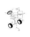
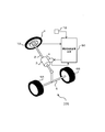
- FIG. 1 is a block diagram showing an electric power steering apparatus according to Embodiment 1 of the present invention.
- an electric power steering apparatus 100 includes a steering handle 1, a steering shaft 2, a speed reducer 3, a motor 4, a tie rod 5, a gear box (not shown), and a pair of steering wheels 6A and 6B.
- the steering handle 1, the steering shaft 2, the tie rod 5, the gear box, and the pair of steering wheels 6A and 6B constitute a steering system.
- the steering handle 1 is fixed to one end of the steering shaft 2.
- the steering handle 1 is operated by a driver.
- the speed reducer 3 is attached to the middle part of the steering shaft 2.
- the motor 4 is coupled to the steering shaft 2 via the speed reducer 3.
- An intermediate portion of the tie rod 5 is connected to the steering shaft 2 via a gear box.
- the pair of steering wheels 6A and 6B are rotatably attached to both ends of the tie rod 5.
- the steering angle of the pair of steered wheels 6A and 6B is changed according to the change in the rotation angle of the steering handle 1 by the driver.
- the driving torque of the motor 4 is amplified by the speed reducer 3 and applied to the steering shaft 2. Accordingly, the amplified torque of the motor 4 and the steering torque generated when the driver rotates the steering handle 1 are applied to the steering shaft 2.
- the steering shaft 2 and the steering wheels 6A, 6B are rotated against the road surface reaction torque transmitted from the steering wheels 6A, 6B to the steering shaft 2 by the sum of the drive torque and the steering torque by the motor 4.
- the steering handle 1 is provided with a steering angle sensor 10 as a steering angle detection means.
- the steering angle sensor 10 generates a steering angle signal corresponding to the steering angle of the steering handle 1.
- a steering torque sensor 11 as a steering torque detecting means is attached to the steering shaft 2.
- the steering torque sensor 11 generates a steering torque signal corresponding to the steering torque acting on the steering shaft 2.
- the operation of the electric power steering apparatus 100 is controlled by the steering control apparatus main body 50.
- a steering angle signal from the steering angle sensor 10, a steering torque signal from the steering torque sensor 11, and a vehicle speed signal from the vehicle speed sensor 12 as vehicle speed detection means are input to the steering control device main body 50.
- the steering control device main body 50 monitors the steering angle, the steering torque, and the vehicle speed using the steering angle signal, the steering torque signal, and the vehicle speed signal. Further, the steering control device main body 50 monitors the drive current of the motor 4. Further, the steering control device main body 50 stores changes in the monitored steering angle, steering torque, vehicle speed, and driving current of the motor 4.
- the steering control device main body 50 calculates a command current (steering auxiliary current) necessary to generate the driving torque of the motor 4 based on the steering angle signal, the steering torque signal, and the vehicle speed signal. Further, the steering control device main body 50 executes current control (feedback control) so that the motor current based on the motor current signal matches the command current, and applies an applied voltage to the motor 4 by the current control.
- a command current steering auxiliary current
- current control feedback control
- FIG. 2 is a block diagram showing the steering control device main body 50 of FIG.
- the steering control device body 50 includes an assist command current calculation unit 51, a road surface reaction force torque calculation unit 52, a reaction force command current calculation unit 53, a subtraction unit 54, a current control unit 55, a drive circuit 56, and a current detection.
- a current sensor 57 is provided as means.
- the calculation process of calculating the command current from the steering angle by the road surface reaction force torque calculation unit 52, the reaction force command current calculation unit 53, and the subtraction unit 54 corresponds to the filter process.
- the assist command current calculation unit 51, the road surface reaction force torque calculation unit 52, the reaction force command current calculation unit 53, and the subtraction unit 54 constitute a command current calculation system 60.
- the command current calculation system 60 calculates a command current.
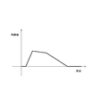
- the assist command current calculation unit 51 calculates a basic assist command current for reducing the driver's steering torque using the vehicle speed and the steering torque. Specifically, in the assist command current calculation unit 51, an assist map as shown in FIG. 3, that is, the value of the basic assist command current with respect to the vehicle speed and the steering torque is registered in advance. The assist command current calculation unit 51 calculates a basic assist command current using the assist map, the vehicle speed, and the steering torque. The driving torque of the motor 4 corresponding to this basic assist command current is defined as the basic assist torque.
- Road surface reaction torque calculating unit 52 uses the vehicle speed and the steering angle, and a vehicle model shown in equation below (1) to (13) (a type of filter), caster trail and due torque M F, the self-aligning Each of the torque M S and the road surface reaction torque M R is calculated. Note that the self-aligning torque M S is generated as a result of the tire lateral force F yF being unevenly distributed on the contact surfaces of the steered wheels 6A and 6B, as shown in the following equation (9). A matic trail-induced torque M S1 and a tire torsion torque M S2 are included.
- Reaction force command current calculation unit 53 receives the calculation results of the road surface reaction torque M R from the road surface reaction force torque computing section 52. Further, the reaction force command current calculating unit 53, using the road surface reaction torque M R and the vehicle speed, calculates a reaction force instruction current. The reaction force command current so as to correspond to the magnitude of the road surface reaction torque M R, a current for adjusting the magnitude of the driving torque of the motor 4.
- the subtraction unit 54 receives the calculation result of the basic assist command current from the assist command current calculation unit 51. Further, the subtracting unit 54 receives the calculation result of the reaction force command current from the reaction force command current calculation unit 53. Further, the subtracting unit 54 subtracts the reaction force command current from the basic assist command current, and sends the current value obtained by the subtraction to the current control unit 55 as the command current of the motor 4.
- the current control unit 55 monitors the motor current via the current sensor 57. Further, the current control unit 55 calculates the applied voltage of the motor 4 based on the command current and the motor current so that the current flowing through the motor 4 matches the command current.
- the drive circuit 56 performs PWM (Pulse Width Modulation) drive so that the applied voltage calculated by the current control unit 55 is applied to the motor 4.
- the steering control device main body 50 is configured by hardware (not shown) including an arithmetic processing device (CPU), a storage device (ROM, RAM, etc.), a signal input / output device, a drive circuit 56, and a current sensor 57. can do.
- This hardware storage device stores programs for realizing the functions of the assist command current calculation unit 51, the road surface reaction force torque calculation unit 52, the reaction force command current calculation unit 53, the subtraction unit 54, and the current control unit 55. Has been.
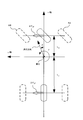
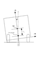
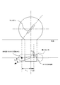
- Command current calculation system 60 reads the vehicle speed V and the steering angle theta h, calculates the road surface reaction torque M R by using the vehicle model shown in the following equation (1) to (13). Note that these vehicle models are stored in advance in the steering control device main body 50. Further, various symbols (parameters) used for the arithmetic processing of the steering control device main body 50 are defined as shown in FIG. Further, various symbols used for the arithmetic processing of the steering control device main body 50 correspond to the vehicle models shown in FIGS.
- a motion model from the steering angle ⁇ h to the tire lateral force F yF generated on the steered wheels is expressed by the following equations (1) to (6). Conversion from steering angle ⁇ h to steering wheel steering angle ⁇ :
- Model road surface reaction torque M R that acts on the steering shaft 2 by the tire lateral force can be expressed by the following equation (7).
- the self-aligning torque M S includes a pneumatic trail generated when the tire lateral force F yF is unevenly distributed on the ground contact surfaces of the steered wheels 6A and 6B.
- the cause torque M S1 and the torsion torque M S2 of the tire are included.
- the pneumatic trail-derived torque M S1 can be calculated using the equation (10).
- the torsion torque M S2 of the tire can be modeled as shown in equations (11) to (13).
- Expressions (11) to (13) have a phase advance element based on the tire torsional rigidity with respect to the front wheel side slip angle, in other words, a high-pass filter characteristic in which the gain is based on the tire torsional rigidity.
- the torsion torque M S2 is expressed.
- the tire torsion response time constant T 1 is a time constant that changes according to the vehicle speed, and can be set as shown in Expression (13). Further, the tire torsion response distance L 1 means a travel distance required until the twist of the tire after steering is eliminated. Further, the road surface reaction torque M R is the steering frequency range, the phase advances than tire lateral force F yF, the effect has a characteristic that becomes more pronounced at low speed.
- overall steering gear ratio G S may sometimes be variably designed by the steering angle, there is a case where that's rack axial force estimated value actually different from the road surface reaction force torque acting from the road surface to the steering shaft. Equation (8), (10), (12) as in, by considering the overall steering gear ratio G S, it can be calculated actual road surface reaction force torque acting from the road surface to the steering shaft with high accuracy to Become.
- the vehicle model shown in the equations (1) to (13) includes the vehicle speed V as a parameter (variable). Therefore, the calculation result of the caster based on the vehicle model trail caused torque M F and the self-aligning torque M S is varied according to the vehicle speed V.
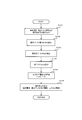
- FIG. 9 is a flowchart showing the operation of the command current calculation system 60 of FIG.
- the command current calculation system 60 reads the stored vehicle speed, steering torque, and steering angle (step S101). Thereafter, the command current calculation system 60 calculates a basic assist command current using the assist map and the read vehicle speed and steering torque (step S102).
- the command current computing system 60 calculates the road surface reaction torque M R by using the vehicle model shown in the previous equation (1) to (13) (step S103). Thereafter, the command current calculation system 60 sets the conversion gain K 1 using a preset conversion gain map (see FIG. 10) and the vehicle speed (step S104). Then, the command current calculation system 60 calculates the reaction force command current I R by multiplying the conversion gain K 1 and the road surface reaction force torque M R as shown in the following equation (14) (step S105).
- the command current computing system 60 subtracts the reaction force command current I R from the basic assist command current, calculates a command current (step S106). Information on the calculated command current is sent to the current control unit 55, and the current control unit 55 controls the current corresponding to the command current to flow through the motor 4. Then, the command current calculation system 60 repeatedly executes the processes of steps S101 to S106.
- the conversion gain K 1 from the road surface reaction force torque M R to the reaction force command current I R is set to a value different from the vehicle speed. Specifically, in the extremely low speed range including 0 km / h at the vehicle speed, the main purpose is to reduce the steering torque. Therefore, as the reaction force command current I R is zero at very low speed range, in terms of gain K 1 is set. As a result, the steering torque in the extremely low speed region is lightened, and the steering feeling in the extremely low speed region becomes important.
- the low-speed range conversion gain K 1 is set to a larger value. This improves the steering feeling. Furthermore, in the high speed range, the inclination of the steering torque with respect to the steering angle is inherently large. For this reason, the conversion gain K 1 is set to a value smaller than that in the low speed region. As a result, the inclination of the steering torque with respect to the steering angle increases within an appropriate range.
- the goal is to obtain a control effect for such a vehicle that realizes a natural steering feeling close to manual steering. That is, the road surface reaction force torque M R acting on the steering wheels 6A and 6B is calculated, and a reaction force based on the calculated road surface reaction force torque M R is applied from the motor 4 to the steering shaft 2 to simulate the reaction force.
- the goal is to obtain a control effect that increases the road surface reaction torque and realizes a natural steering feeling close to manual steering.
- the solid line in FIG. 11 (a), (b) was determined from the measured data of the real vehicle of the vehicle speed 40 km / h, a frequency characteristic from the steering angle to the caster trail caused torque M F.
- the solid lines in FIGS. 11C and 11D are frequency characteristics from the steering angle to the self-aligning torque M S obtained from the actual measurement data at a vehicle speed of 40 km / h.
- the phase differs between the caster rail- induced torque M F (the same phase as the tire lateral force F yF ) and the self-aligning torque M S. Specifically, the phase of the self-aligning torque M S is ahead of the phase of the caster trail caused torque M F. As for the fall degree of the gain in the vicinity of the steering frequency 2 Hz, towards self-aligning torque M S is smaller than the caster trail caused torque M F.
- FIG. 11 (a), (b) is the frequency response from the steering angle in the vehicle model to the caster trail caused torque M F.
- the broken lines in FIGS. 11C and 11D are frequency responses from the steering angle to the self-aligning torque M S in the vehicle model. As shown in FIG. 11, by considering the torsion torque M S2 of the tire, the self-aligning torque M S becomes close to the actually measured value.
- road surface reaction torque M R is the sum of the caster trail caused torque M F and the self-aligning torque M S.
- the road surface reaction torque M R is calculated by approximating M F + M S1 without considering the torsion torque M S2 of the tire as in the conventional device, the calculated road surface reaction torque M R the difference between the actual road surface reaction torque M R is relatively large.
- FIG. 12B shows a characteristic in which the solid line and the broken line match.
- FIG. 12 (a) calculates a reaction force instruction current road surface reaction torque M R, results when artificially increases the road surface reaction torque M R (road surface reaction torque M The result of increasing the steering reaction torque by R and the assist torque by the reaction force command current is shown.
- the steering characteristic of the manual steer can be enhanced by maintaining the phase characteristic of the manual steer and increasing the feeling of steering reaction force.
- FIG. 12 (c) the shows dashed lines, when the reaction force command current is zero, the frequency characteristic from the steering angle to the road surface reaction torque M R of (d).
- the solid line in FIG. 12 (c), (d) calculates a reaction force instruction current M F + M S1, pseudo result of increasing the road surface reaction torque M R (road surface reaction torque M R and the reaction force The result of increasing the steering reaction torque with the assist torque by the command current is shown.
- the gain increase characteristic is substantially the same as the characteristic shown by the solid line in FIG. 12A, but the phase is approximately in the frequency region of 1 Hz or more. delayed than the characteristic of the road surface reaction torque M R shown by the broken line in b).
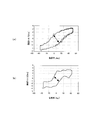
- FIG. 13 is a Lissajous waveform of the steering torque with respect to the steering angle in 0.2 Hz sine wave steering (low frequency steering) when the vehicle speed is 40 km / h.
- This 0.2 Hz sine wave steering corresponds to a normal lane change and is a frequently performed steering pattern.
- FIG. 13A shows the result of assisting the driver's steering based on the steering torque detected by the steering torque sensor 11 and the vehicle speed detected by the vehicle speed sensor 12.
- the greater the hysteresis width of the Lissajous waveform the greater the feeling of friction.
- the feeling of steering reaction force is insufficient, and it is difficult for the driver to know whether the vehicle is traveling straight or turning, and the steering feeling becomes worse.
- control and vehicle characteristics are adjusted in order to eliminate such deterioration of steering feeling.
- both have appropriate values, and the steering feeling becomes worse even when the feeling of friction is extremely small or the feeling of steering reaction force is extremely large.
- the Lissajous waveforms shown in FIGS. 13B to 13D are controlled by the following specifications so that the inclination of the steering torque with respect to the steering angle near the origin is the same.
- the Lissajous waveform in FIG. 13B shows the result of subtracting the reaction force command current proportional to the steering angle from the basic assist command current. According to FIG. 13B, it can be seen that the inclination of the steering torque with respect to the steering angle is large, and the feeling of the steering reaction force is improved.
- the Lissajous waveform in FIG. 13 (c) drives the motor 4 with the command current obtained by subtracting the reaction force command current proportional to M F + M S1 in phase with the tire lateral force F yF from the basic assist command current. It is the result.
- the inclination of the steering torque with respect to the steering angle near the origin is increased to the same level as in FIG. 13B, and the steering reaction force feeling is improved. Recognize. Further, the hysteresis width of the Lissajous waveform of FIGS. 13C and 13D is narrower than the Lissajous waveform of FIG. 13A and wider than the Lissajous waveform of FIG. From this, it can be seen that the feeling of friction is moderate and a natural steering feeling is obtained.
- the phase and gain of M F + M S1 that are in phase with the tire lateral force F yF are substantially equal to the phase and gain of road surface reaction torque M R. For this reason, even with M F + M S1 , the road surface reaction torque increases in a pseudo manner, and a natural steering feeling close to manual steering can be realized.
- FIG. 14 shows the result of 2 Hz sine wave steering (high frequency steering) when the vehicle speed is 40 km / h.
- the 2 Hz sine wave steering corresponds to a steeper lane change or a steering performed when returning to the vicinity of the center of the lane when the vehicle passes by one side in the same lane.
- the 2 Hz sine wave steering is a steering pattern that is performed relatively frequently, although not as much as 0.2 Hz sine wave steering.
- the control specifications in FIGS. 14A to 14D are the same as the control specifications in FIGS. 13A to 13D.
- the Lissajous waveform in FIG. 14A is a result of assisting the driver's steering based on the steering torque and the vehicle speed. According to FIG. 14A, it can be seen that the feeling of friction is large because the hysteresis width of the Lissajous waveform is large. It can also be seen that the steering reaction force feeling is insufficient because the inclination of the steering torque with respect to the steering angle is small. Further, since the steering torque after turning back is almost zero, it is understood that the reaction torque for returning the steering wheel position to the center position is insufficient.
- the Lissajous waveform in FIG. 14B is the result of subtracting the reaction force command current proportional to the steering angle from the basic assist command current. According to FIG. 14B, it can be seen that the steering torque after the turn-back is substantially zero.
- the Lissajous waveform in FIG. 14C drives the motor 4 with a command current obtained by subtracting a reaction force command current proportional to M F + M S1 that is in phase with the tire lateral force F yF from the basic assist command current. It is the result.
- the phase of M F + M S1 is different from the phase of the actual road reaction torque. For this reason, the hysteresis width is extremely narrow when the steering angle is around 0 degrees. Further, the steering torque after switching back is almost zero. As described above, in the control specifications shown in FIGS. 14B and 14C, there is a problem that the Lissajous waveform is not smooth, resulting in a non-smooth steering reaction force feeling.
- the steering control device main body 50 is a filter including a predetermined frequency characteristic that expresses vehicle characteristics from the steering angle to the self-aligning torque M S of the steered wheels 6A and 6B. And the driving torque of the motor 4 is set based on the filtering result.
- the predetermined frequency characteristic of the filter includes the characteristic of the torsion torque M S2 of the tire.
- the steering control device main body 50 filters the steering angle signal using a filter including a predetermined frequency characteristic expressing the vehicle characteristic from the steering angle to the pneumatic trail-induced torque M S1 , and the filter processing result is obtained. Based on this, the driving torque of the motor 4 is corrected. With this configuration, it is possible to achieve a natural steering feeling without a sense of incongruity, and to easily realize subtle optimization of the steering feeling.
- the vehicle model shown in the equations (1) to (13) may be designed so as to be limited to the specific vehicle speed. In this case, it is possible to reduce the calculation load and the memory capacity for calculation.
- Embodiment 2 the road surface reaction force torque computing section 52, the road surface by multiplying a conversion gain K 1 to the reaction force torque M R, was calculated reaction force instruction current.
- the road surface reaction force torque computing section 52 is multiplied by a conversion gain K 1, K 2 in each of the caster trail caused torque M F and the self-aligning torque M S, their The reaction force command current I R is calculated by calculating the sum.
- the outline of the configuration of the steering control device main body 50 of the second embodiment is the same as that of the steering control device main body 50 of the first embodiment.
- a part of the processing contents of the road surface reaction force torque calculation unit 52 and the reaction force command current calculation unit 53 of the steering control device main body 50 of the second embodiment are the road surface reaction force torque calculation unit 52 and the reaction force command of the first embodiment. This is different from the current calculation unit 53.
- Embodiment 1 will be mainly described.
- the road surface reaction torque calculation unit 52 of the second embodiment takes in the vehicle speed signal and the steering angle signal. Further, the road surface reaction force torque calculation unit 52 uses the vehicle speed signal and the steering angle signal and the vehicle model shown in the equations (1) to (13) to generate the caster rail-induced torque M F and the self-aligning torque M S. Are calculated respectively.
- conversion gain maps for conversion gains K 1 and K 2 as predetermined gains are registered in advance.
- Convert gain K 1, K 2 is a value for converting the respective caster trail caused torque M F and the self-aligning torque M S to the reaction force command current.
- the conversion gains K 1 and K 2 are set in advance to different values with respect to the vehicle speed, as shown in FIG. 10, as with the conversion gain K 1 of the first embodiment.
- reaction force command current calculation unit 53 sets the conversion gains K 1 and K 2 using the conversion gain map and the vehicle speed. Further, reaction force command current calculation unit 53, the road surface reaction force torque computing section 52 caster trail caused torque M F and the self-aligning torque M S calculated by, respectively multiplied by a conversion gain K 1, K 2, these The reaction force command current I R is calculated by obtaining the sum of.
- the main purpose is to reduce the steering torque. Therefore, if the reaction force command current is set to 0, the steering torque is reduced and the operability is emphasized. Steering feeling. In the low speed range, since the inclination of the steering torque with respect to the steering angle is originally small, the steering feeling can be improved by setting the conversion gains K 1 and K 2 large.
- the inclination of the steering torque with respect to the steering angle is originally large in the high speed range, if the conversion gains K 1 and K 2 are set smaller than in the low speed range, the inclination of the steering torque with respect to the steering angle is increased within an appropriate range. In addition, it is possible to obtain appropriate operability while improving reaction feeling (so-called on-center feeling). Thus, by making K 1 and K 2 variable according to the vehicle speed, the steering feeling can be improved in the entire vehicle speed range. Different values can be set for the conversion gains K 1 and K 2 .
- a map value (limit value setting map) for a limit value for the vehicle speed is registered in the steering control device main body 50 in advance.
- the reaction force command current calculation unit 53 sets a limit value according to the vehicle speed.
- the reaction force command current calculation unit 53 limits the magnitude of the reaction force command current I R to be within the set limit value.
- the torsional torque M S2 of the tire has a differential characteristic with respect to the pneumatic trail-derived torque M S1 .
- the torsional torque M S2 of the tire tends to be more noisy than the torque M S1 caused by the pneumatic trail. Therefore, for example, the road surface reaction force torque calculation unit 52 may perform a low-pass filter process as shown in the following equation (18) on the torsion torque M S2 .
- s in Formula (18) is a Laplace operator.
- the time constant T 2 of the low-pass filter is set in advance to be equal to or higher than the human steering frequency limit of 5 Hz and higher than the frequency band affecting the steering feeling.
- the upper limit is set in advance to the Nyquist frequency for the calculation cycle of the road surface reaction force torque calculation unit 52.
- FIG. 16 is a flowchart showing the operation of the command current calculation system 60 according to the second embodiment of the present invention.
- the command current calculation system 60 reads the stored vehicle speed, steering torque, and steering angle (step S201). Thereafter, the command current calculation system 60 calculates a basic assist command current using the assist map and the read vehicle speed and steering torque (step S202).
- the command current calculation system 60 includes a read vehicle speed and the steering angle, by using the vehicle model shown in the previous equation (1) to (13), the caster trail caused torque M F and the self-aligning torque M S Calculate (step S203). Thereafter, the command current calculation system 60 sets the conversion gains K 1 and K 2 using the conversion gain map (see FIG. 10) and the vehicle speed set in advance (step S204).
- the command current calculation system 60 limits the calculated reaction force command current I R so as to be within the limit value (step S206). Then, the command current calculation system 60 subtracts the reaction force command current I R from the basic assist command current, calculates a command current (step S207). Information on the calculated command current is sent to the current control unit 55, and the current control unit 55 controls the motor 4 so that a current having a magnitude corresponding to the command current flows. Then, the command current calculation system 60 repeatedly executes the processes of steps S201 to S206.
- FIG. 17 is an explanatory diagram for explaining the effect of the steering control device main body 50 according to the second embodiment of the present invention.
- the Lissajous waveform in FIG. 17 (a) is 40 km / h of 0 when the motor 4 is driven by the command current obtained by subtracting the reaction force command current proportional to the self-aligning torque M S from the basic assist command current. This is a result of 2 Hz sine wave steering.
- FIG. 17A shows that the inclination of the steering torque with respect to the steering angle near the origin increases to the same level as in FIG. 13B, and the reaction force feeling is improved. Further, the hysteresis width of the Lissajous waveform of FIG. 17A is narrower than the Lissajous waveform of FIG. 13A and wider than the Lissajous waveform of FIG. From this, it can be seen that an appropriate friction feeling is obtained and a more natural steering feeling is obtained.
- the Lissajous waveform in FIG. 17B is a 2 Hz sine wave when the motor 4 is driven by a command current obtained by subtracting a reaction force command current proportional to the self-aligning torque M S from the basic assist command current. This is the result of steering. According to FIG. 17B, it can be seen that the rate of change of the steering torque with respect to the steering angle near 0 degrees is increased, and a more appropriate reaction force feeling can be realized. In addition, it can be seen that the steering torque after turning back is not near 0, and a smooth Lissajous waveform is obtained. Furthermore, it turns out that it is an appropriate hysteresis width and the feeling of friction can be reduced.
- the ratio is high. Therefore, it is calculated reaction force instruction current I R based on the self aligning torque M S, obtaining a reaction force command current I R result of calculating the equivalent Lissajous waveform based on the road surface reaction torque M R Therefore, the same effect as in the first embodiment can be obtained.
- the command current calculation system 60 calculates the sum of the caster rail-derived torque M F multiplied by the conversion gain K 1 and the self-aligning torque M S multiplied by the conversion gain K 2 , and the reaction force command current I R Is calculated. With this configuration, it is possible to adjust the proportion between the caster trail caused torque M F and the self-aligning torque M S occupied in pseudo-road surface reaction torque is increased. That is, the slope of the steering torque (steering reaction force feeling) with respect to the steering angle near the origin in the Lissajous waveform and the hysteresis width (friction feeling) can be adjusted independently.
- the reaction force command current based on the road surface reaction torque M R a natural steering feeling without close discomfort manual steering is achieved.
- the feeling according to the driver's preference such as adjusting the feeling of friction by slightly reducing the hysteresis width of the Lissajous waveform while enhancing the steering reaction force feeling as it is.
- the hysteresis width of the Lissajous waveform can be slightly narrowed by setting K 1 larger than K 2 .
- the conversion gain K 1 is set to 0, it is possible to adjust to increase only the reaction force feeling due to the self-aligning torque M S. As a result, it is possible to emphasize the manual steering feeling in which the self-aligning torque M S acts.
- the reaction force command current calculation unit 53 multiplies the torques M F and M S by the conversion gains K 1 and K 2 as shown in the equation (19), thereby obtaining the reaction force command current I R. Asked.
- the reaction force command current I R is calculated as a command current calculation as a map value for the caster rail-derived torque M F , the self-aligning torque M S or the road surface reaction force torque M R, and the vehicle speed. It may be registered in advance in the system 60.
- Embodiment 3 the assist command current calculation unit 51 calculates the basic assist command current based on the vehicle speed and the steering torque.
- the steering torque sensor 11 is omitted in the first embodiment, the assist command current calculation section 51, and the road surface reaction torque M R calculated by the road surface reaction force torque computing section 52 Based on the vehicle speed, the basic assist command current is calculated.
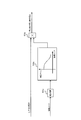
- FIG. 18 is a block diagram showing an electric power steering apparatus according to Embodiment 3 of the present invention.
- the outline of the configuration of the electric power steering apparatus 100 according to the third embodiment is the same as that of the electric power steering apparatus 100 according to the first embodiment.
- the configuration of the electric power steering apparatus 100 according to the third embodiment is different from the electric power steering apparatus 100 according to the first embodiment in that the steering torque sensor 11 in the first embodiment is omitted.
- FIG. 19 is a block diagram showing the steering control device main body 50 of FIG. 19, the outline of the configuration of the steering control device main body 50 according to the third embodiment is the same as the configuration of the steering control device main body 50 according to the first embodiment.
- the assist command current calculation unit 51 calculates the road surface reaction force torque from the road surface reaction force torque calculation unit 52 instead of the steering torque signal from the steering torque sensor 11. The difference from the steering control device main body 50 of the first embodiment is that the result is received.
- Assist command current calculation section 51 and the road surface reaction torque M R calculated by the road surface reaction force torque computing section 52, based on the vehicle speed, to calculate the basic assist command current.
- the value of the basic assist command current with respect to the vehicle speed and the road surface reaction force torque is stored in advance as an assist map.
- the assist command current calculation unit 51 calculates a basic assist command current corresponding to the vehicle speed and the road surface reaction force torque using the assist map.
- Other configurations and operations are the same as those in the first embodiment.
- the road surface reaction torque M R acting on the steering shaft 2 includes the torsion torque M S2 of the tire. For this reason, even if it is the structure which abbreviate
- the assist command current calculation unit 51 may be omitted when applied to a vehicle having a small caster rail, pneumatic trail, or cornering power.
- the reaction force command current calculated by the reaction force command current calculator 53 may be used as the command current of the motor 4.
- the present invention can also be applied to a steering apparatus that employs a system in which the steering wheel and the steering wheel are mechanically disconnected and the road surface reaction torque is not transmitted to the steering wheel, as in the steer-by-wire system.
- the reaction force command current calculated by the reaction force command current calculation unit 53 may be the command current of the motor attached to the steering wheel side.
- Embodiment 4 FIG.
- the reaction force command current calculation section 53 to calculate the reaction force command current I R with a road surface reaction torque M R and the vehicle speed.
- the reaction force command current computing section 53 by using the road surface reaction torque M R and the vehicle speed, it calculates a reaction force instruction current I R, reaction force command with a steering torque The current I R is corrected.
- FIG. 20 is a block diagram showing a steering control device main body 50 according to Embodiment 4 of the present invention.
- FIG. 21 is an explanatory diagram for explaining a correction process for the reaction force command current by the reaction force command current calculation unit 53 of FIG.
- the reaction force command current calculation unit 53 of the fourth embodiment calculates a reaction force command current I R as in the first or second embodiment.
- the reaction force command current calculation unit 53 includes an absolute value calculation unit 53a, a correction gain setting unit 53b, and a multiplication unit 53c.
- the absolute value calculation unit 53 a receives the steering torque signal from the steering torque sensor 11 and calculates the absolute value of the steering torque.
- a correction gain map that is a map value of the correction gain with respect to the steering torque is registered in advance. This correction gain map is registered such that the correction gain decreases with an increase in steering torque.
- the correction gain setting unit 53b sets a correction gain corresponding to the absolute value of the steering torque calculated by the absolute value calculation unit 53a based on the correction gain map.
- the multiplication unit 53c corrects the reaction force command current I R calculated by the reaction force command current calculation unit 53 in the same manner as in the first or second embodiment by multiplying it by a correction gain set by the steering torque. Other configurations and operations are the same as those in the first or second embodiment.
- the correction gain map is registered so that the correction gain decreases as the steering torque increases.
- the reaction force command current can be reduced and an increase in the steering torque can be suppressed.
- the steering torque is also small, so that the correction gain is not decreased and the applied road surface reaction torque can be maintained.
- the correction gain is registered in the correction gain setting unit 53b in association with the steering torque.
- the reaction force command current calculation unit 53 is configured to be able to calculate the steering speed from the steering angle signal, and a correction gain corresponding to the steering speed corresponding to the steering speed is set as the correction gain setting unit 53b. May be registered in advance. In this case, for example, if the correction gain is set to decrease as the steering speed increases, the reaction force command current decreases and the reaction force decreases in a situation where the driver must steer the large steering angle in a short time. Although the feeling is reduced, steering can be performed with a small steering torque.
- a correction gain corresponding to the steering angle may be registered in advance in the correction gain setting unit 53b.
- the correction gain is set to a different value in the left / right steering, the left / right difference in the road surface reaction force torque characteristic originally possessed by the vehicle can be suppressed.
- the left and right steering directions can be determined by the sign (+ ⁇ ⁇ ) of the steering torque, and different correction gains may be set by the sign of the steering torque.
- Embodiment 5 the road surface reaction torque calculating unit 52 corrects the vehicle model shown in the above equations (1) to (13) based on the vehicle weight (vehicle weight) or the road surface friction coefficient.
- the outline of the configuration of the steering control device main body 50 of the fifth embodiment is the same as the outline of the configuration of the steering control device main body 50 of the first embodiment. Further, in the steering control device main body 50 of the fifth embodiment, the point that the vehicle weight sensor 13 and the road surface friction coefficient sensor 14 are connected and the internal processing of the road surface reaction force torque calculation unit 52 are the same as those in the first embodiment. Different from the steering control device main body 50. Here, the difference from Embodiment 1 will be mainly described.
- FIG. 22 is a block diagram showing a steering control device main body 50 according to Embodiment 5 of the present invention.
- a vehicle weight sensor 13 as vehicle weight acquisition means detects or estimates the vehicle weight m, and generates a vehicle weight signal corresponding to the vehicle weight m.
- the road surface friction coefficient sensor 14 serving as a road surface friction coefficient acquisition unit detects or estimates a road surface friction coefficient or a physical quantity corresponding thereto, and generates a road surface friction coefficient signal.
- the vehicle weight m is included as a parameter (variable) in the arithmetic expressions of the vehicle model shown in the equations (1) to (13). Therefore, the road surface reaction torque calculation unit 52 monitors the change in the vehicle weight m using the vehicle weight signal from the vehicle weight sensor 13 and changes the characteristics of the vehicle model based on the vehicle weight m.
- the change in the vehicle weight m is mainly caused by the weight of the occupant, the load or the fuel, the sprung mass of the vehicle model represented by the equations (1) to (13) based on the vehicle weight m.
- m S may be changed. That is, the vehicle weight m and the sprung mass m S that are fixed values in the first embodiment are variables in the fifth embodiment.
- the cornering powers K f and K r of the front and rear wheels change according to the vehicle weight and the road surface friction coefficient.
- the road surface reaction force torque calculator 52 changes the cornering powers K f and K r of the vehicle model based on the vehicle weight and the road surface friction coefficient.
- the cornering powers K f and K r of the vehicle model may be set to increase as the vehicle weight increases.
- the cornering powers K f and K r of the vehicle model may be set to be small on a slippery road surface having a low road surface friction coefficient.
- the actual angle including the self-aligning torque M S from the steering angle is more practical.
- the road surface reaction force torque M R close to can be calculated. As a result, it is possible to be able to increase the road surface reaction torque M R corresponding to the vehicle weight and road changes in a pseudo manner, to achieve a more natural steering feeling.
- the cornering powers K f and K r of the vehicle model are changed based on both the vehicle weight and the road surface friction coefficient.
- the present invention is not limited to this example, and the cornering powers K f and K r of the vehicle model may be changed based on only one of the vehicle weight and the road surface friction coefficient.
- the filter including the vehicle model is changed so as to change in response to a change in at least one of the vehicle speed, steering torque, steering angle, vehicle weight, road friction coefficient, steering speed, and steering direction of the vehicle. It may be set. Thereby, it is possible to realize a natural steering feeling that is appropriate and has no sense of incongruity according to the vehicle speed and the steering situation.
- the vehicle model represented by the equations (1) to (13) is used when calculating the self-aligning torque M S.
- the present invention is not limited to this example.
- a vehicle model registered in advance is identified from the measured steering angle and the measured self-aligning torque without using the vehicle model represented by equations (1) to (13), and the identified vehicle model is used.
- the reaction force command current is calculated, the same effects as in the first to fifth embodiments can be obtained.
- the steering control device main body 50 monitors the change in the steering angle via the steering angle sensor 10.
- the rotation angle of the motor 4 and the rotation angles (steering angles) of the steering wheels 6A and 6B are physical quantities that change according to the steering angle. Accordingly, the steering control device main body 50 may monitor the change in the steering angle by monitoring the change in these physical quantities (through the other sensors) without using the steering angle sensor 10.
- the assist torque generated by the motor 4 is calculated based on the reaction force command current and the basic assist command current.
- the present invention is not limited to this example, and the assist torque in the first to fifth embodiments is calculated using the self-aligning torque M S calculated using the vehicle model shown in the equations (1) to (13) or the road surface reaction. it may be replaced by a variety of motor torque based on the torque M R.
Abstract
Description
実施の形態1.
図1は、この発明の実施の形態1による電動パワーステアリング装置を示す構成図である。
図1において、電動パワーステアリング装置100は、操舵ハンドル1、ステアリング軸2、減速器3、モータ4、タイロッド5、ギアボックス(図示せず)、及び一対の操舵輪6A,6Bを有している。操舵ハンドル1、ステアリング軸2、タイロッド5、ギアボックス、及び一対の操舵輪6A,6Bは、操舵系を構成している。操舵ハンドル1は、ステアリング軸2の一端に固定されている。また、操舵ハンドル1は、運転者によって操作される。 Hereinafter, embodiments for carrying out the present invention will be described with reference to the drawings.
1 is a block diagram showing an electric power steering apparatus according to
In FIG. 1, an electric
操舵角θhから操舵輪の舵角δへの換算:

Conversion from steering angle θ h to steering wheel steering angle δ:


これに加えて、この算出した路面反力トルクMRを用いてモータ4の駆動トルクを補正することにより、タイヤの捩りトルクMS2を考慮していない従来装置に比べて、路面反力トルクMRを精度良く擬似的に増加することができる。特に、運転者が急なレーンチェンジ等の比較的早い操舵を行った場合にも、マニュアルステアに近く違和感のない自然な操舵フィーリングを実現することができる。 Further, the predetermined frequency characteristic of the filter includes the characteristic of the torsion torque M S2 of the tire. With this configuration, by calculating the road surface reaction torque M R as steering control apparatus
In addition, by correcting the drive torque of the
実施の形態1では、路面反力トルク演算部52が、路面反力トルクMRに換算ゲインK1を乗じて、反力指令電流を算出した。これに対して、実施の形態2では、路面反力トルク演算部52が、キャスタートレール起因トルクMFとセルフアライニングトルクMSとのそれぞれに換算ゲインK1,K2を乗じて、それらの和を求めることにより、反力指令電流IRを算出する。
In the first embodiment, the road surface reaction force


この場合、K1をK2よりも大きく設定することで、リサージュ波形のヒステリシス幅を若干細くすることが可能になる。この結果、マニュアルステアに近く違和感のない自然な操舵フィーリングを実現しつつ、微妙な操舵フィーリングの最適化を容易に実現することができる。 Here, in the first embodiment, the reaction force command current based on the road surface reaction torque M R, a natural steering feeling without close discomfort manual steering is achieved. However, for example, in high-frequency steering, there is a case where it is desired to finely adjust the feeling according to the driver's preference, such as adjusting the feeling of friction by slightly reducing the hysteresis width of the Lissajous waveform while enhancing the steering reaction force feeling as it is. is there.
In this case, the hysteresis width of the Lissajous waveform can be slightly narrowed by setting K 1 larger than K 2 . As a result, it is possible to easily realize subtle optimization of the steering feeling while realizing a natural steering feeling that is close to manual steering and has no sense of incongruity.
実施の形態1,2では、アシスト指令電流演算部51が、車速及び操舵トルクに基づいて基本アシスト指令電流を算出した。これに対して、実施の形態3では、実施の形態1における操舵トルクセンサ11が省略され、アシスト指令電流演算部51が、路面反力トルク演算部52によって算出された路面反力トルクMRと、車速とに基づいて、基本アシスト指令電流を算出する。
In the first and second embodiments, the assist command
実施の形態1では、反力指令電流演算部53が、路面反力トルクMR及び車速を用いて反力指令電流IRを算出した。これに対して、実施の形態4では、反力指令電流演算部53が、路面反力トルクMR及び車速を用いて、反力指令電流IRを算出し、操舵トルクを用いて反力指令電流IRを補正する。
In the first embodiment, the reaction force command
実施の形態5では、路面反力トルク演算部52が、車重(車両重量)又は路面摩擦係数に基づいて、先の式(1)~(13)に示す車両モデルを補正する。
In the fifth embodiment, the road surface reaction
Claims (6)
- 動力を操舵系に付与するモータの駆動を制御する操舵制御装置であって、
前記操舵系の操舵角に応じた操舵角信号を生成する操舵角検出手段から受けた操舵角信号を、前記操舵角から、前記操舵系の操舵輪のセルフアライニングトルクまでの車両特性を表現した所定の周波数特性を含むフィルタを用いてフィルタ処理し、そのフィルタ処理結果に基づいて、前記モータの駆動トルクを設定する操舵制御装置本体
を備える操舵制御装置。 A steering control device for controlling driving of a motor for applying power to a steering system,
The steering angle signal received from the steering angle detection means that generates a steering angle signal corresponding to the steering angle of the steering system represents vehicle characteristics from the steering angle to the self-aligning torque of the steering wheel of the steering system. A steering control device comprising: a steering control device main body that performs a filtering process using a filter including a predetermined frequency characteristic, and sets a driving torque of the motor based on a result of the filtering process. - 前記フィルタの所定の周波数特性には、前記操舵輪のタイヤ自体が弾性変形によって捩れることより発生し前記操舵系に作用するトルクであるタイヤの捩りトルクの特性が含まれている
請求項1記載の操舵制御装置。 The predetermined frequency characteristic of the filter includes a characteristic of a torsion torque of the tire that is generated when the tire of the steering wheel itself is twisted by elastic deformation and acts on the steering system. Steering control device. - 前記操舵制御装置本体は、前記操舵角から、キャスタートレールとタイヤ横力とにより発生し前記操舵系に作用するトルクであるキャスタートレール起因トルクまでの車両特性を表現した所定の周波数特性を含むフィルタを用いて、前記操舵角信号をフィルタ処理し、そのフィルタ処理結果に基づいて、前記駆動トルクを補正する
請求項1又は請求項2に記載の操舵制御装置。 The steering control device main body includes a filter including a predetermined frequency characteristic representing a vehicle characteristic from the steering angle to a caster rail-derived torque that is a torque generated by a caster rail and a tire lateral force and acting on the steering system. The steering control device according to claim 1, wherein the steering angle signal is filtered to correct the driving torque based on a result of the filtering process. - 前記操舵制御装置本体は、
前記操舵角から、前記操舵輪のセルフアライニングトルクまでの車両特性を表現した所定の周波数特性を含むフィルタを用いて、前記操舵角信号をフィルタ処理し、
前記操舵角から、キャスタートレールとタイヤ横力とにより発生し前記操舵系に作用するトルクであるキャスタートレール起因トルクまでの車両特性を表現した所定の周波数特性を含むフィルタを用いて、前記操舵角信号をフィルタ処理し、
これらのフィルタ処理結果のそれぞれに所定のゲインを乗じて、そのゲインを乗じた結果に基づいて、前記駆動トルクを補正する
請求項1又は請求項2に記載の操舵制御装置。 The steering control device body is
Filtering the steering angle signal using a filter including a predetermined frequency characteristic expressing vehicle characteristics from the steering angle to the self-aligning torque of the steering wheel,
The steering angle signal using a filter including a predetermined frequency characteristic expressing a vehicle characteristic from the steering angle to a caster rail-derived torque that is a torque generated by a caster rail and a tire lateral force and acting on the steering system. Filter
The steering control device according to claim 1 or 2, wherein each of the filter processing results is multiplied by a predetermined gain, and the drive torque is corrected based on the result of multiplication. - 前記操舵制御装置本体は、
運転者から前記操舵系に加えられる操舵トルクに応じた操舵トルク信号を生成する操舵トルク検出手段からの前記操舵トルク信号に基づいて、基本アシストトルクを算出し、
その算出した基本アシストトルクを用いて、前記駆動トルクを補正する
請求項1又は請求項2に記載の操舵制御装置。 The steering control device body is
A basic assist torque is calculated based on the steering torque signal from the steering torque detection means that generates a steering torque signal corresponding to the steering torque applied to the steering system from the driver,
The steering control device according to claim 1 or 2, wherein the driving torque is corrected using the calculated basic assist torque. - 前記フィルタの特性は、
前記車両の車速と、
運転者から前記操舵系に加えられる操舵トルクを検出する操舵トルク検出手段によって検出された操舵トルクと、
前記操舵角検出手段によって検出された操舵角と、
車重を検出あるいは推定する車重取得手段によって取得された車重と、
路面摩擦係数を検出あるいは推定する路面摩擦係数取得手段によって取得された路面摩擦係数と、
前記操舵角に基づく操舵速度と、
前記操舵角及び前記操舵トルクのいずれか一方に基づく操舵方向と
のうちの少なくともいずれか1つの変化に対応して変化する
請求項1又は請求項2に記載の操舵制御装置。 The characteristics of the filter are:
Vehicle speed of the vehicle;
Steering torque detected by steering torque detection means for detecting steering torque applied to the steering system from the driver;
A steering angle detected by the steering angle detection means;
The vehicle weight acquired by the vehicle weight acquisition means for detecting or estimating the vehicle weight,
The road friction coefficient acquired by the road friction coefficient acquisition means for detecting or estimating the road friction coefficient, and
A steering speed based on the steering angle;
The steering control device according to claim 1 or 2, wherein the steering control device changes corresponding to a change in at least one of a steering direction based on one of the steering angle and the steering torque.
Priority Applications (5)
| Application Number | Priority Date | Filing Date | Title |
|---|---|---|---|
| CN201080064248.4A CN102770328B (en) | 2010-02-19 | 2010-02-19 | Steering controller |
| EP10846116.1A EP2537732B1 (en) | 2010-02-19 | 2010-02-19 | Steering controller |
| US13/574,047 US9242670B2 (en) | 2010-02-19 | 2010-02-19 | Power steering controller with compensation for tire deformation and caster |
| PCT/JP2010/052527 WO2011101979A1 (en) | 2010-02-19 | 2010-02-19 | Steering controller |
| JP2012500431A JP5436654B2 (en) | 2010-02-19 | 2010-02-19 | Steering control device |
Applications Claiming Priority (1)
| Application Number | Priority Date | Filing Date | Title |
|---|---|---|---|
| PCT/JP2010/052527 WO2011101979A1 (en) | 2010-02-19 | 2010-02-19 | Steering controller |
Publications (1)
| Publication Number | Publication Date |
|---|---|
| WO2011101979A1 true WO2011101979A1 (en) | 2011-08-25 |
Family
ID=44482597
Family Applications (1)
| Application Number | Title | Priority Date | Filing Date |
|---|---|---|---|
| PCT/JP2010/052527 WO2011101979A1 (en) | 2010-02-19 | 2010-02-19 | Steering controller |
Country Status (5)
| Country | Link |
|---|---|
| US (1) | US9242670B2 (en) |
| EP (1) | EP2537732B1 (en) |
| JP (1) | JP5436654B2 (en) |
| CN (1) | CN102770328B (en) |
| WO (1) | WO2011101979A1 (en) |
Cited By (5)
| Publication number | Priority date | Publication date | Assignee | Title |
|---|---|---|---|---|
| JP2014058225A (en) * | 2012-09-18 | 2014-04-03 | Nissan Motor Co Ltd | Vehicular steering control unit and vehicular steering control method |
| CN104029715A (en) * | 2013-03-07 | 2014-09-10 | 福特全球技术公司 | Method for identifying increased friction in power-assisted rack-and-pinion steering systems |
| CN106553690A (en) * | 2015-09-28 | 2017-04-05 | 本田技研工业株式会社 | Steering device for motor vehicle |
| US10160481B2 (en) | 2015-03-10 | 2018-12-25 | Nsk Ltd. | Electric power steering apparatus and control apparatus determining parameter set to the same |
| WO2023203812A1 (en) * | 2022-04-20 | 2023-10-26 | 日本精工株式会社 | Control device for vehicle steering system |
Families Citing this family (26)
| Publication number | Priority date | Publication date | Assignee | Title |
|---|---|---|---|---|
| JP5533903B2 (en) * | 2012-01-27 | 2014-06-25 | トヨタ自動車株式会社 | Vehicle control device |
| JP6107158B2 (en) * | 2013-01-18 | 2017-04-05 | 株式会社ジェイテクト | Electric power steering device |
| JP6180771B2 (en) * | 2013-03-29 | 2017-08-16 | 株式会社ジェイテクト | Electric power steering device |
| JP6378887B2 (en) * | 2014-02-04 | 2018-08-22 | Kyb株式会社 | Electric power steering device |
| JP6314552B2 (en) * | 2014-03-07 | 2018-04-25 | 株式会社ジェイテクト | Electric power steering device |
| DE112015001321T5 (en) * | 2014-03-19 | 2016-12-15 | Hitachi Automotive Systems, Ltd. | Electric power steering apparatus and control apparatus for an electric power steering apparatus |
| FR3023612B1 (en) * | 2014-07-09 | 2016-07-29 | Jtekt Europe Sas | METHOD FOR ESTIMATING REAL-TIME RELIEF TO RODS WITHIN AN ASSISTED STEERING MECHANISM |
| US10179601B2 (en) * | 2014-08-22 | 2019-01-15 | Nsk Ltd. | Electric power steering apparatus |
| DE102016110791A1 (en) | 2015-06-15 | 2016-12-15 | Steering Solutions Ip Holding Corporation | Gesture control for a retractable steering wheel |
| US20170072994A1 (en) * | 2015-09-14 | 2017-03-16 | Mando Corporation | Apparatus and method for controlling electric power steering system |
| KR102350043B1 (en) * | 2015-11-20 | 2022-01-12 | 주식회사 만도 | System and method for controlling autonomous steering |
| DE102017108692A1 (en) * | 2016-04-25 | 2017-10-26 | Steering Solutions Ip Holding Corporation | Control of electric power steering using system state predictions |
| JP6750341B2 (en) * | 2016-06-22 | 2020-09-02 | 株式会社ジェイテクト | Steering control device |
| US10131360B2 (en) * | 2016-08-12 | 2018-11-20 | GM Global Technology Operations LLC | Methods and systems for estimating road surface friction |
| KR101835406B1 (en) * | 2016-08-26 | 2018-03-09 | 현대모비스 주식회사 | Motor driven power steering control apparatus |
| CN107618614B (en) * | 2017-09-11 | 2019-10-11 | 广东工业大学 | A kind of two take turns the control method of single-track vehicle and its balance |
| EP3640118A4 (en) * | 2017-10-13 | 2020-11-11 | NSK Ltd. | Electric power steering device |
| US11180187B2 (en) * | 2018-04-27 | 2021-11-23 | Jtekt Corporation | Motor control device |
| TWI722289B (en) * | 2018-06-07 | 2021-03-21 | 華創車電技術中心股份有限公司 | Motor vehicle steering control system and steering control method |
| JP7247508B2 (en) * | 2018-09-28 | 2023-03-29 | 日本電産株式会社 | Steering control device and power steering device |
| JP7211149B2 (en) * | 2019-02-21 | 2023-01-24 | トヨタ自動車株式会社 | electric power steering device |
| CN110294016A (en) * | 2019-08-02 | 2019-10-01 | 武汉雄韬氢雄燃料电池科技有限公司 | A kind of automatic Pilot AVG steering control system and method |
| KR20210031075A (en) * | 2019-09-11 | 2021-03-19 | 주식회사 만도 | Steering control device and method thereof, and steering system |
| JP7200210B2 (en) * | 2020-12-25 | 2023-01-06 | 本田技研工業株式会社 | moving body |
| DE102021202482B4 (en) * | 2021-03-15 | 2023-06-29 | Continental Automotive Technologies GmbH | Control device and method for steering angle control of a vehicle |
| US20230079933A1 (en) * | 2021-09-08 | 2023-03-16 | GM Global Technology Operations LLC | Systems and methods for determining whether a vehicle is in an understeer or oversteer situation |
Citations (13)
| Publication number | Priority date | Publication date | Assignee | Title |
|---|---|---|---|---|
| JPH01278881A (en) * | 1988-04-30 | 1989-11-09 | Jidosha Kiki Co Ltd | Control method for motor-driven power steering device |
| JPH0885469A (en) * | 1994-09-16 | 1996-04-02 | Bridgestone Corp | Vehicle steering characteristic control method |
| JP2001233231A (en) * | 2000-02-25 | 2001-08-28 | Mitsubishi Electric Corp | Electric power steering control device and its controlling method |
| JP2002087309A (en) * | 2000-07-13 | 2002-03-27 | Mazda Motor Corp | Electric power steering device for automobile |
| JP2002145100A (en) | 2000-11-17 | 2002-05-22 | Nsk Ltd | Control device of electric power steering device |
| JP2004175280A (en) * | 2002-11-28 | 2004-06-24 | Mitsubishi Electric Corp | Automatic steering device for vehicle |
| JP2004338616A (en) | 2003-05-16 | 2004-12-02 | Toyota Motor Corp | Electric power steering device for vehicle |
| JP2006281880A (en) * | 2005-03-31 | 2006-10-19 | Showa Corp | Electric power steering device |
| JP2007513008A (en) * | 2003-12-04 | 2007-05-24 | コンティネンタル・テーベス・アクチエンゲゼルシヤフト・ウント・コンパニー・オッフェネ・ハンデルスゲゼルシヤフト | Method and apparatus for assisting a vehicle operator in stabilizing a vehicle |
| JP2007269251A (en) | 2006-03-31 | 2007-10-18 | Jtekt Corp | Electric power steering device |
| JP2007314005A (en) * | 2006-05-25 | 2007-12-06 | Nsk Ltd | Control device of electric power steering system |
| JP2008114687A (en) | 2006-11-02 | 2008-05-22 | Nsk Ltd | Electric power steering device |
| JP2008149961A (en) * | 2006-12-19 | 2008-07-03 | Jtekt Corp | Electric power steering device |
Family Cites Families (17)
| Publication number | Priority date | Publication date | Assignee | Title |
|---|---|---|---|---|
| JPH11287749A (en) * | 1998-03-31 | 1999-10-19 | Aisin Seiki Co Ltd | Road surface friction coefficient estimation device |
| JP3951205B2 (en) * | 1998-05-19 | 2007-08-01 | 株式会社デンソー | Power steering method and power steering apparatus |
| JP4019813B2 (en) * | 2001-07-12 | 2007-12-12 | 株式会社豊田中央研究所 | Physical quantity estimation device, road friction state estimation device, steering angle neutral point estimation device, and air pressure drop estimation device |
| JP3950729B2 (en) * | 2002-04-23 | 2007-08-01 | アイシン精機株式会社 | Vehicle motion control device |
| DE10332023A1 (en) * | 2002-07-31 | 2004-02-12 | Daimlerchrysler Ag | Motor vehicle steering method in which the torque to be applied to the steering wheels is determined by a control unit based on a calculated transverse force to be applied to them |
| EP1625993B1 (en) * | 2003-05-16 | 2009-06-17 | Mitsubishi Denki Kabushiki Kaisha | Steering control device |
| JP4213994B2 (en) * | 2003-05-28 | 2009-01-28 | 株式会社豊田中央研究所 | Tire grip degree estimation device and method, and driving state control method |
| CN2823083Y (en) * | 2005-08-19 | 2006-10-04 | 比亚迪股份有限公司 | Line transmission steering control device for automobile |
| JP4314489B2 (en) * | 2005-09-16 | 2009-08-19 | トヨタ自動車株式会社 | Vehicle steering device |
| JP4737402B2 (en) * | 2005-09-21 | 2011-08-03 | 株式会社ジェイテクト | Electric power steering device |
| JP4872298B2 (en) * | 2005-10-04 | 2012-02-08 | 日本精工株式会社 | Control device for electric power steering device |
| JP4984602B2 (en) * | 2006-03-31 | 2012-07-25 | 日本精工株式会社 | Control device for electric power steering device |
| US8200392B2 (en) * | 2006-05-10 | 2012-06-12 | Toyota Jidosha Kabushiki Kaisha | Vehicular steering control device |
| JP4997472B2 (en) * | 2007-01-09 | 2012-08-08 | 株式会社ジェイテクト | Electric power steering device |
| JP4362137B2 (en) * | 2007-02-28 | 2009-11-11 | 三菱電機株式会社 | Vehicle steering system |
| JP4329859B2 (en) * | 2007-12-12 | 2009-09-09 | トヨタ自動車株式会社 | Steering control device |
| JP4666083B2 (en) * | 2009-02-12 | 2011-04-06 | 株式会社デンソー | Electric power steering device |
-
2010
- 2010-02-19 US US13/574,047 patent/US9242670B2/en not_active Expired - Fee Related
- 2010-02-19 WO PCT/JP2010/052527 patent/WO2011101979A1/en active Application Filing
- 2010-02-19 JP JP2012500431A patent/JP5436654B2/en active Active
- 2010-02-19 EP EP10846116.1A patent/EP2537732B1/en active Active
- 2010-02-19 CN CN201080064248.4A patent/CN102770328B/en active Active
Patent Citations (13)
| Publication number | Priority date | Publication date | Assignee | Title |
|---|---|---|---|---|
| JPH01278881A (en) * | 1988-04-30 | 1989-11-09 | Jidosha Kiki Co Ltd | Control method for motor-driven power steering device |
| JPH0885469A (en) * | 1994-09-16 | 1996-04-02 | Bridgestone Corp | Vehicle steering characteristic control method |
| JP2001233231A (en) * | 2000-02-25 | 2001-08-28 | Mitsubishi Electric Corp | Electric power steering control device and its controlling method |
| JP2002087309A (en) * | 2000-07-13 | 2002-03-27 | Mazda Motor Corp | Electric power steering device for automobile |
| JP2002145100A (en) | 2000-11-17 | 2002-05-22 | Nsk Ltd | Control device of electric power steering device |
| JP2004175280A (en) * | 2002-11-28 | 2004-06-24 | Mitsubishi Electric Corp | Automatic steering device for vehicle |
| JP2004338616A (en) | 2003-05-16 | 2004-12-02 | Toyota Motor Corp | Electric power steering device for vehicle |
| JP2007513008A (en) * | 2003-12-04 | 2007-05-24 | コンティネンタル・テーベス・アクチエンゲゼルシヤフト・ウント・コンパニー・オッフェネ・ハンデルスゲゼルシヤフト | Method and apparatus for assisting a vehicle operator in stabilizing a vehicle |
| JP2006281880A (en) * | 2005-03-31 | 2006-10-19 | Showa Corp | Electric power steering device |
| JP2007269251A (en) | 2006-03-31 | 2007-10-18 | Jtekt Corp | Electric power steering device |
| JP2007314005A (en) * | 2006-05-25 | 2007-12-06 | Nsk Ltd | Control device of electric power steering system |
| JP2008114687A (en) | 2006-11-02 | 2008-05-22 | Nsk Ltd | Electric power steering device |
| JP2008149961A (en) * | 2006-12-19 | 2008-07-03 | Jtekt Corp | Electric power steering device |
Non-Patent Citations (1)
| Title |
|---|
| KAZUHIRO YUBAI: "Scheduled H00 Seigyo o Mochiita Dendo Power Steering Kudokei no Sekkei Shuho Design Method of Electric Power", THE TRANSACTIONS OF THE INSTITUTE OF ELECTRICAL ENGINEERS OF JAPAN C, vol. 119-C, no. 1, 1 January 1999 (1999-01-01), XP008168127 * |
Cited By (5)
| Publication number | Priority date | Publication date | Assignee | Title |
|---|---|---|---|---|
| JP2014058225A (en) * | 2012-09-18 | 2014-04-03 | Nissan Motor Co Ltd | Vehicular steering control unit and vehicular steering control method |
| CN104029715A (en) * | 2013-03-07 | 2014-09-10 | 福特全球技术公司 | Method for identifying increased friction in power-assisted rack-and-pinion steering systems |
| US10160481B2 (en) | 2015-03-10 | 2018-12-25 | Nsk Ltd. | Electric power steering apparatus and control apparatus determining parameter set to the same |
| CN106553690A (en) * | 2015-09-28 | 2017-04-05 | 本田技研工业株式会社 | Steering device for motor vehicle |
| WO2023203812A1 (en) * | 2022-04-20 | 2023-10-26 | 日本精工株式会社 | Control device for vehicle steering system |
Also Published As
| Publication number | Publication date |
|---|---|
| CN102770328A (en) | 2012-11-07 |
| JP5436654B2 (en) | 2014-03-05 |
| JPWO2011101979A1 (en) | 2013-06-17 |
| CN102770328B (en) | 2014-12-03 |
| EP2537732B1 (en) | 2020-09-02 |
| US9242670B2 (en) | 2016-01-26 |
| US20120296525A1 (en) | 2012-11-22 |
| EP2537732A1 (en) | 2012-12-26 |
| EP2537732A4 (en) | 2017-05-10 |
Similar Documents
| Publication | Publication Date | Title |
|---|---|---|
| JP5436654B2 (en) | Steering control device | |
| US7092805B2 (en) | Steering apparatus for steerable vehicle | |
| EP3041752B1 (en) | Steering apparatus and steering controller | |
| JP5126357B2 (en) | Vehicle steering device | |
| JP5533822B2 (en) | Electric power steering control device | |
| JP4670161B2 (en) | Electric power steering device for automobile | |
| JP6078124B1 (en) | Vehicle control apparatus and vehicle control method | |
| US8788147B2 (en) | Method for determining a toothed rack force for a steering device in a vehicle | |
| JP4281828B2 (en) | Electric power steering device | |
| US20100228440A1 (en) | Steering control apparatus and a steering apparatus using the same | |
| JP4807422B2 (en) | Electric power steering system | |
| JP5170496B2 (en) | Electric power steering device | |
| US20090099731A1 (en) | Electric power steering system | |
| JP4280682B2 (en) | Vehicle steering device | |
| JP5223718B2 (en) | Steering load estimation device and electric power steering device | |
| JP2013060198A (en) | Rear wheel steering vehicle | |
| JP2003081119A (en) | Motor-driven power steering device for automobile | |
| JP4806930B2 (en) | Vehicle steering system | |
| JP6737026B2 (en) | Steering control device | |
| JP4517555B2 (en) | Electric power steering device for automobile | |
| CN113474236A (en) | Steering device for vehicle | |
| JP4280695B2 (en) | Vehicle steering device | |
| JP2004299492A (en) | Electric power steering device of automobile | |
| JP6011458B2 (en) | Steering control device | |
| JP2002037106A (en) | Electric power steering device for automobile |
Legal Events
| Date | Code | Title | Description |
|---|---|---|---|
| WWE | Wipo information: entry into national phase |
Ref document number: 201080064248.4 Country of ref document: CN |
|
| 121 | Ep: the epo has been informed by wipo that ep was designated in this application |
Ref document number: 10846116 Country of ref document: EP Kind code of ref document: A1 |
|
| WWE | Wipo information: entry into national phase |
Ref document number: 2012500431 Country of ref document: JP |
|
| WWE | Wipo information: entry into national phase |
Ref document number: 13574047 Country of ref document: US Ref document number: 2010846116 Country of ref document: EP |
|
| WWE | Wipo information: entry into national phase |
Ref document number: 6967/CHENP/2012 Country of ref document: IN |
|
| NENP | Non-entry into the national phase |
Ref country code: DE |