JP4019813B2 - Physical quantity estimation device, road friction state estimation device, steering angle neutral point estimation device, and air pressure drop estimation device - Google Patents
Physical quantity estimation device, road friction state estimation device, steering angle neutral point estimation device, and air pressure drop estimation device Download PDFInfo
- Publication number
- JP4019813B2 JP4019813B2 JP2002183413A JP2002183413A JP4019813B2 JP 4019813 B2 JP4019813 B2 JP 4019813B2 JP 2002183413 A JP2002183413 A JP 2002183413A JP 2002183413 A JP2002183413 A JP 2002183413A JP 4019813 B2 JP4019813 B2 JP 4019813B2
- Authority
- JP
- Japan
- Prior art keywords
- steering
- self
- value
- aligning torque
- sat
- Prior art date
- Legal status (The legal status is an assumption and is not a legal conclusion. Google has not performed a legal analysis and makes no representation as to the accuracy of the status listed.)
- Expired - Fee Related
Links
Images


Classifications
-
- G—PHYSICS
- G01—MEASURING; TESTING
- G01N—INVESTIGATING OR ANALYSING MATERIALS BY DETERMINING THEIR CHEMICAL OR PHYSICAL PROPERTIES
- G01N19/00—Investigating materials by mechanical methods
- G01N19/02—Measuring coefficient of friction between materials
-
- B—PERFORMING OPERATIONS; TRANSPORTING
- B62—LAND VEHICLES FOR TRAVELLING OTHERWISE THAN ON RAILS
- B62D—MOTOR VEHICLES; TRAILERS
- B62D15/00—Steering not otherwise provided for
- B62D15/02—Steering position indicators ; Steering position determination; Steering aids
-
- B—PERFORMING OPERATIONS; TRANSPORTING
- B60—VEHICLES IN GENERAL
- B60T—VEHICLE BRAKE CONTROL SYSTEMS OR PARTS THEREOF; BRAKE CONTROL SYSTEMS OR PARTS THEREOF, IN GENERAL; ARRANGEMENT OF BRAKING ELEMENTS ON VEHICLES IN GENERAL; PORTABLE DEVICES FOR PREVENTING UNWANTED MOVEMENT OF VEHICLES; VEHICLE MODIFICATIONS TO FACILITATE COOLING OF BRAKES
- B60T2210/00—Detection or estimation of road or environment conditions; Detection or estimation of road shapes
- B60T2210/10—Detection or estimation of road conditions
- B60T2210/12—Friction
Landscapes
- Engineering & Computer Science (AREA)
- Chemical & Material Sciences (AREA)
- General Health & Medical Sciences (AREA)
- General Physics & Mathematics (AREA)
- Life Sciences & Earth Sciences (AREA)
- Physics & Mathematics (AREA)
- Analytical Chemistry (AREA)
- Biochemistry (AREA)
- Automation & Control Theory (AREA)
- Health & Medical Sciences (AREA)
- Immunology (AREA)
- Pathology (AREA)
- Combustion & Propulsion (AREA)
- Transportation (AREA)
- Mechanical Engineering (AREA)
- Steering Control In Accordance With Driving Conditions (AREA)
- Control Of Driving Devices And Active Controlling Of Vehicle (AREA)
- Regulating Braking Force (AREA)
Description
【0001】
【発明の属する技術分野】
本発明は、物理量推定装置、路面摩擦状態推定装置、操舵角中立点推定装置、及びタイヤ空気圧低下推定装置に係り、特に、ヒステリシス特性を除去した補正値に基づいて物理量を推定する物理量推定装置、セルフアライニングトルク(SAT)の推定値からクーロン摩擦等の粘性摩擦等の影響によって生じるヒステリシス特性を除去した補正値を求め、求めた補正値に基づいて路面摩擦状態を推定する路面摩擦状態推定装置、ヒステリシス特性を除去した補正値と操舵角とに基づいて操舵角の中立点を推定する操舵角中立点推定装置、及びヒステリシス特性を除去した補正値とSAT基準値に基づいてタイヤの空気圧の低下を推定するタイヤの空気圧低下推定装置に関する。
【0002】
【従来の技術及び発明が解決しようとする課題】
特開平11−287749号公報には、タイヤの操舵角と操舵トルクとを検出すると共に、操舵角に対する操舵トルクの特性を演算し、演算結果に基づいてタイヤが接地する路面の摩擦係数μ(路面μ)を演算する技術が開示されている。
【0003】
この従来技術では、グリップ状態に相当する物理量である路面μを操舵角の変化量に対する操舵トルクの変化量として求めているため、ノイズの影響を受け易い推定手法となっている。すなわち、変化量を求めることはノイズを増幅させる微分を行うことを意味しており、このため推定値はノイズを多く含む値となる。
【0004】
また、この従来技術では、操舵角の切り増し時にのみ路面μを推定しているので、タイヤに与えられる負荷が最も大きくなる最大舵角時には切り増しができないことから摩擦係数を推定できない。本来、タイヤに与えられる負荷が最も大きい、すなわち限界に近いときに路面μの推定、すなわち限界の路面μの推定を行った方が推定精度が向上するが、従来技術では、最大舵角時には路面μの推定ができず、最大舵角時に至る手前でしか路面μの推定ができない、という問題がある。
【0005】
ところで、SATとスリップ角または操舵角との間には、タイヤトレッドのねじれやパワーステアリング装置のクーロン摩擦等によってヒステリシス特性が生じる。このため、操舵角の切り増し時と切り戻し時とでは特性が異なり、スリップ角または操舵角の変化に対するSATの変化に着目する従来の手法では、推定値にばらつきが生じることとなる。
【0006】
また、保舵時にハンドルが動かない程度にドライバが操舵力を減少させた場合、スリップ角または操舵角には変化が生じないにも拘わらずSATが減少する結果、「グリップ状態が低下」したと誤判定される可能性がある。すなわち、上記従来技術では、切り増し時のみ推定を行うことによってこのような誤判定を避けると共に推定値のばらつきを低減させていたが、この結果切り戻しや保舵時にはグリップ状態等の路面摩擦状態を推定できない、という問題がある。
【0007】
また、切戻しや保舵時に路面摩擦状態を推定できないということは、例えば保舵状態で低μ路から高μ路へ乗り移ったり、高μ路から低μ路に乗り移ったりしてグリップ状態が変化した場合には、変化した時点では路面摩擦状態を推定できず、次に操舵角を切り増しするまでグリップ状態の推定ができないことを意味している。このため、従来技術によるグリップ状態の推定値は、速い適応性が要求されるパワーステアリング装置やABSの特性をグリップ状態に応じて切り替える制御パラメータとして利用することはできない。
【0008】
また、特開平11−334634号、及び特開平11−59466号には、操舵角と車速とに基づいて設定された基準操舵トルクと操舵トルクとを比較し、操舵トルクが基準操舵トルクより大きい状態が一定時間継続した場合に、タイヤの空気圧が低下したと判定する技術が記載されている。
【0009】
上記従来技術では、操舵系の摩擦を含む操舵トルクを利用しているため、操舵トルクの空気圧に対する変化がこの摩擦によって影響されるため正確に検出できなくなり、摩擦の影響のために高い精度で空気圧の低下を推定することができない、という問題がある。
【0010】
また、操舵角と操舵トルクとの間には、上記操舵系の摩擦の他に車両運動の動特性の影響も受ける。このため、速い操舵を行ったとき等に推定精度が劣化することが危惧される。
【0011】
上記問題に対する対策として、従来技術では操舵トルクが基準操舵トルクに対して大きい状態が一定時間以上継続した場合という条件を付加し、この条件によって精度劣化の問題を緩和している。しかしながら、この条件によって推定の機会が少なくなり、結果的に推定時間が遅れる、という問題点が新たに生じる。
【0012】
本発明は上記問題点を解消するためになされたもので、推定値にばらつきが生じないようにするためにヒステリシス特性の除去によって精度の高い物理量を推定することができる物理量推定装置、操舵角を切り増ししなくても正確に路面摩擦状態を推定することができる路面摩擦状態推定装置、操舵角の中立点を正確に推定することができる操舵角中立点推定装置、及びタイヤの空気圧低下を推定することができるタイヤの空気圧低下推定装置を提供することを目的とする。
【0013】
【課題を解決するための手段】
上記目的を達成するために本発明の物理量推定装置は、ハンドル角もしくは操舵輪のスリップ角に対するヒステリシス特性を持たない操舵輪の操舵状態を出力する第1の出力手段と、操舵トルクとアシストトルクとから推定されるセルフアライニングトルク推定値を出力する第2の出力手段と、前記セルフアライニングトルク推定値から、ハンドル角もしくは操舵輪のスリップ角に対するヒステリシス特性を除去してセルフアライニングトルク補正値を演算するヒステリシス除去手段と、前記操舵輪の操舵状態と前記セルフアライニングトルク補正値とに基づいて車両走行時の車輪状態及び路面状態の一方に関する物理量を推定する推定手段とを含んで構成したものである。
【0014】
本発明によれば、ハンドル角もしくは操舵輪のスリップ角に対するヒステリシス特性を持つセルフアライニングトルク推定値からハンドル角もしくは操舵輪のスリップ角に対するヒステリシス特性が除去されたセルフアライニングトルク補正値に基づいて車両走行時の車輪状態及び路面状態の一方に関する物理量を推定しているため、精度の高い物理量を推定することができる。これによって、精度の高いセルフアライニングトルク補正値から更に他の車両走行時の車輪状態及び路面状態の一方に関する物理量を推定することができるため、推定した物理量にばらつきが生じることがない。
【0015】
本発明では、操舵輪の操舵状態を、例えば、ハンドル角もしくは操舵輪のスリップ角とすることができる。
【0016】
このセルフアライニングトルク補正値は、セルフアライニングトルク推定値の変化に対するセルフアライニングトルク補正値の変化の比で表される勾配を有する演算式であって、クーロン摩擦によってセルフアライニングトルク推定値が変動する領域の勾配を該領域以外の領域の勾配より小さくした各領域毎に異なる演算式によって演算することが可能である。
【0017】
また、ヒステリシス特性は、ヒステリシス特性を持つ物理量とヒステリシス特性を持たない上記と同一の物理量との所定の物理的関係をグラフやテーブル等で表しておき、この物理的関係に基づいてヒステリシス特性を持つ物理量からヒステリシス特性を持たない物理量へ変換することにより、除去することができる。この場合、以前の経歴に応じて初期値を予め定めることで変換が容易になる。
【0018】
車両走行時の車輪状態及び路面状態の一方に関する物理量(例えば、タイヤの空気圧低下、または路面摩擦状態)は、前記操舵輪のスリップ角とセルフアライニングトルク補正値とに基づいて、または、操舵輪のスリップ角に応じて設定されるセルフアライニングトルク基準値と、セルフアライニングトルク補正値とに基づいて、推定することができる。
【0019】
また、スリップ角の変化に対するセルフアライニングトルク補正値の変化の比で表されるセルフアライニングトルク補正値の勾配に基づいても、車両走行時の車輪状態及び路面状態の一方に関する物理量を推定することができる。
【0020】
さらに、車両走行時の車輪状態及び路面状態の一方に関する物理量は、操舵輪のスリップ角と、スリップ角基準値及びセルフアライニングトルク補正値のいずれか一方とに基づいて推定することもできる。
【0021】
このスリップ角基準値は、セルフアライニングトルク推定値の変化に対するスリップ角基準値の変化の比で表される勾配を有する演算式であって、クーロン摩擦によってセルフアライニングトルク推定値が変動する領域の勾配を該領域以外の領域の勾配より小さくした各領域毎に異なる演算式によっても演算してもよい。
【0022】
本発明の路面摩擦状態推定装置は、操舵角を検出する操舵角センサと、車速を検出する車速センサと、操舵トルクを検出するトルクセンサと、操舵のアシストトルクを検出するアシストトルクセンサと、操舵角と車速とに基づいて、操舵輪のスリップ角を推定するスリップ角推定手段と、操舵トルクとアシストトルクとに基づいて、セルフアライニングトルク推定値を出力するセルフアライニングトルク推定手段と、前記セルフアライニングトルク推定値と前記スリップ角との関係に基づいて、セルフアライニングトルク推定値に対する、ハンドル角もしくは操舵輪のスリップ角に対するヒステリシス特性が除去されたスリップ角基準値を演算するヒステリシス除去手段と、前記スリップ角基準値と前記スリップ角とから路面摩擦状態を推定する摩擦状態推定手段とを含んで構成されている。
【0023】
本発明の路面摩擦状態推定装置のスリップ角推定手段は、車両運動モデルに基づいて、操舵角と車速とを用いて操舵輪(例えば、前輪)のスリップ角を推定する。セルフアライニングトルク(SAT)推定手段は、操舵トルクとアシストトルクとに基づいて、具体的には操舵トルクとアシストトルクとを加算することによって、路面反力であるSATを推定する。操舵トルクは、例えば、ハンドルと同軸上に取り付けられたトルクセンサによって検出され、アシストトルクは、例えば、電動パワーステアリング装置の電流から演算される。
【0024】
なお、操舵トルクとアシストトルクを加算した値から操舵角速度に比例して発生する粘性摩擦トルクを減算することによってSAT推定精度を向上させることもできる。さらに、SATは操舵角の他、操舵角速度も利用して特願2000−370704号に記載の外乱オブザーバの手法によって推定しても良い。外乱オブザーバの手法を用いることによって、パワーステアリング装置の慣性によって生じるトルクを考慮したSATの推定が可能となる。
【0025】
ヒステリシス除去手段は、セルフアライニングトルク推定値と前記スリップ角との関係に基づいて、ハンドル角もしくは操舵輪のスリップ角に対するヒステリシス特性が除去されたセルフアライニングトルク推定値に対するスリップ角基準値を演算する。
【0026】
すなわち、ヒステリシス除去手段は、ヒステリシス特性を有するセルフアライニングトルクとスリップ角との物理的関係に基づいて、セルフアライニングトルク推定値に対するスリップ角を補正値として演算することができる。すなわち、SAT推定手段によって推定されたSAT推定値からパワーステアリング装置のクーロン摩擦等によって生じるヒステリシス特性を考慮したスリップ角(スリップ角基準値)を補正値として出力する。スリップ角基準値は、グリップ状態が充分に高く余裕がある操舵領域において発生する操舵輪、例えば前輪のスリップ角であるので、セルフアライニングトルクの推定値に対するヒステリシス特性が除去されている。
【0027】
摩擦状態推定手段は、スリップ角推定手段によって推定された操舵輪のスリップ角とヒステリシス除去手段から出力されるスリップ角基準値とを比較し、グリップ状態、すなわち路面摩擦状態が低下する程、スリップ角基準値に比較してスリップ角が大きくなることを利用してグリップ状態すなわち路面摩擦状態を推定する。
【0028】
また、ヒステリシス除去手段は、上記の除去方法に代えて、セルフアライニングトルク推定値とヒステリシス特性を除去したセルフアライニングトルク補正値との物理的関係に基づいて、セルフアライニングトルク推定値からヒステリシス特性を除去したセルフアライニングトルクをセルフアライニングトルク補正値として演算するようにしてもよい。この場合、セルフアライニングトルクの推定値から直接ヒステリシス特性を除去したセルフアライニングトルク(SAT補正値)が演算される。
【0029】
摩擦状態推定手段は、スリップ角推定手段によって推定された操舵輪のスリップ角に車速やタイヤ種別に応じて変化する係数を乗じて算出されたSAT基準値と、SAT補正値とを比較し、グリップ状態、すなわち路面摩擦状態が低下する程、SAT基準値に比較してSAT補正値が小さくなることを利用してグリップ状態すなわち路面摩擦状態を推定する。
【0030】
以上説明したように、本発明によれば、セルフアライニングトルクに基づいてヒステリシス特性を除去した補正値を出力し、この補正値に基づいて路面摩擦状態を推定しているので、全操舵角範囲において正確に路面摩擦状態を推定することができる。
【0031】
また、本発明の操舵角中立点推定装置は、操舵角を検出する操舵角センサと、操舵トルクを検出するトルクセンサと、操舵のアシストトルクを検出するアシストトルクセンサと、操舵トルクとアシストトルクとに基づいて、セルフアライニングトルク推定値を出力するセルフアライニングトルク推定手段と、前記セルフアライニングトルク推定値からハンドル角もしくは操舵輪のスリップ角に対するヒステリシス特性を除去して、該推定値が0になったときの値を初期値としてセルフアライニングトルク補正値を演算するヒステリシス除去手段と、前記セルフアライニングトルク補正値と前記操舵角とに基づいて、セルフアライニングトルク補正値が0となるときの操舵角を操舵角の中立点として推定する中立点推定手段とを含んで構成されている。
【0032】
本発明のセルフアライニングトルク(SAT)推定手段は、上記で説明したように操舵トルクとアシストトルクとに基づいてSATを推定する。ヒステリシス除去手段は、SATの推定値が0になったときの値を初期値とし、ハンドル角もしくは操舵輪のスリップ角に対するヒステリシス特性を有するSATとハンドル角もしくは操舵輪のスリップ角に対するヒステリシス特性を除去したSATとの物理的関係からハンドル角もしくは操舵輪のスリップ角に対するヒステリシス特性を除去したSAT補正値を出力する。そして、中立点推定手段は、このSAT補正値と操舵角とに基づいて、補正値が0となるときの操舵角を操舵角の中立点として推定する。
【0033】
本発明のタイヤの空気圧低下推定装置は、横加速度を検出する横加速度センサと、ヨー角速度を検出するヨー角速度センサと、操舵トルクを検出するトルクセンサと、操舵のアシストトルクを検出するアシストトルクセンサと、横加速度とヨー角速度とに基づいて、操舵輪のサイドフォースを推定するサイドフォース推定手段と、操舵トルクとアシストトルクとに基づいて、セルフアライニングトルク推定値を出力するセルフアライニングトルク推定手段と、前記セルフアライニングトルク推定値からハンドル角もしくは操舵輪のスリップ角に対するヒステリシス特性を除去してセルフアライニングトルク補正値を演算するヒステリシス除去手段と、前記セルフアライニングトルク補正値と前記サイドフォースとに基づいて、タイヤの空気圧が低下したか否かを推定する空気圧低下推定手段とを含んで構成されている。
【0034】
このタイヤの空気圧低下推定装置では、操舵角センサと車速センサとに代えて、横加速度を検出する横加速度センサと、ヨー角速度を検出するヨー角速度センサと、を設け、横加速度とヨー角速度とに基づいて、操舵輪のサイドフォースを推定し、セルフアライニングトルク補正値とサイドフォースとに基づいて、タイヤの空気圧が低下したか否かを推定するようにしてもよい。
【0035】
タイヤの空気圧の低下は、セルフアライニングトルク補正値と操舵輪のスリップ角に応じて設定されるセルフアライニングトルク基準値とに基づいて、前記セルフアライニングトルク補正値と前記操舵輪のサイドフォースに応じて設定されるセルフアライニングトルク基準値とに基づいて、または、スリップ角の変化に対するセルフアライニングトルク補正値の変化の比で表されるセルフアライニングトルク補正値の勾配に基づいて、推定することができる。
【0036】
さらに、サイドフォースの変化に対するセルフアライニングトルク補正値の変化の比で表されるセルフアライニングトルク補正値の勾配に基づいて、タイヤの空気圧が低下したか否かを推定するようにしてもよい。
【0037】
空気圧低下判定手段で演算されるSAT補正値とSAT基準値との比は、空気圧低下時には大きくなる値であり、この値が閾値を超えた場合に空気圧低下の判定を行うことができる。しかし、この値は、同時にグリップ状態を表す値でもあり、低μ走行時等グリップ低下時に小さな値となる。このため、SAT補正値とSAT基準値との比が空気圧低下判定の閾値を超えた場合には空気圧低下と判定し、SAT補正値とSAT基準値との比がグリップ低下判定の閾値を下回った場合にはグリップ低下と判定することができる。
【0038】
なお、グリップ低下に起因するSAT補正値とSAT基準値との比の低下は操舵に伴って発生するものであり、比較的変化が速いのに対し、空気圧低下に起因するSAT補正値とSAT基準値との比の増加は変化がゆっくりしている。このため、SAT補正値とSAT準値との比をオンライン最小2乗法等によって同定する場合には、グリップ度推定のためのロジックに対し、空気圧推定のロジックは忘却係数を大きく設定したり、デシメーションと呼ばれるデータの間引きを行ってSAT補正値とSAT基準値の比のゆっくりとした変化を捉えることが望まれる。また、空気圧低下の判定を行う場合には、グリップ低下の影響を受けないスリップ角が小さな直進状態付近のデータを用いることが望まれるため、スリップ角が大きな比較的大きな操舵を行ったときのデータは選別によって除去することも考えられる。
【0039】
【発明の実施の形態】
以下、図面を参照して本発明を前輪によって操舵する車両に適用した場合の実施の形態を詳細に説明する。まず、第1の実施の形態の路面摩擦状態推定装置について説明する。
【0040】
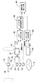
図1に示すように、車両に搭載された電動パワーステアリング装置には、ステアリングシャフト10の上端部に固定されたステアリングホイール(ハンドル)12が設けられている。ステアリングシャフト10の下端部は、ラック・アンド・ピニオン式のステアリングギヤ14に連結されている。
【0041】
ステアリングギヤ14のラックの両側部にはタイロッド16が各々連結されており、各タイロッド16の先端部の各々にはサスペンション機構を介してタイヤが連結されている。
【0042】
また、ステアリングシャフト10には、操舵角を検出する操舵角センサ18、及び操舵トルクを検出するトルクセンサ20がステアリングシャフトと同軸上に取り付けられている。操舵角センサ18は、ステアリングホイール12の回転により生じる操舵角を検出して操舵角信号を出力する。また、トルクセンサ20は、運転者がステアリングホイール12を回転することによりステアリングシャフト10に発生した回転トルクを検出し、ステアリングホイール12の回転操作方向に応じた操舵トルク信号を出力する。
【0043】
このトルクセンサ20から出力された操舵トルク信号は、パワーステアリング装置用コンピュータ及びモータ駆動回路を含んで構成された電気制御装置22に入力される。
【0044】
ステアリングシャフト10のトルクセンサ20取付位置より下側には、一対のすぐばかさ歯車等で構成された減速機24が取り付けられている。減速機24は、電気制御装置22によって制御される電気モータ26の回転軸に連結されている。電気制御装置22によって電気モータ26を駆動し、電気モータの回転力を減速機24を介してステアリングシャフト10に伝達することにより、ステアリングホイール12の操舵力をパワーアシストすることができる。
【0045】
また、車両には、車体速度(車速)を検出する車速センサ30が取り付けられており、電気制御装置22には電動パワーステアリング装置に流れる電流からパワーアシストトルクを検出してアシストトルク信号を出力するアシストトルクセンサ32が取り付けられている。
【0046】
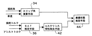
上記の操舵角センサ18及び車速センサ30は、機能ブロックで考えたときにスリップ角推定手段、SAT推定手段、スリップ角基準値演算手段、及び摩擦状態推定手段として機能するマイクロコンピュータのスリップ角推定手段34に接続されている。スリップ角推定手段34は、操舵角及び車速に基づいて操舵輪である前輪のスリップ角を演算する。また、操舵トルクセンサ20及びアシストトルクセンサ32は、操舵トルク及びアシストトルクに基づいてSATを推定するSAT推定手段36に接続されている。
【0047】
SAT推定手段36は、推定されたSATからスリップ角基準値を演算するスリップ角基準値演算手段38に接続されている。
【0048】
なお、上記ではスリップ角推定手段34、SAT推定手段36、スリップ角基準値演算手段38、及び摩擦状態推定手段40を1つのマイクロコンピュータで構成したが、別々の装置で構成してもよい。
【0049】
以下、本実施の形態の各手段の作用を説明する。スリップ角推定手段34は、入力された操舵角信号及び車速信号に基づいて、車両運動の動特性を利用して次式の状態方程式を用いて前輪のスリップ角を推定する。
【0050】
【数1】

ただし、
v:横速度(m/s)、
r:ヨー角速度(rad/s)、
αf:前輪スリップ角(rad)、
u:車速(m/s)、
cf:前輪コーナリングパワー(N/rad)、
cr:後輪コーナリングパワー(N/rad)、
Lf:前軸重心間距離(m)、
Lr:後軸重心間距離(m)、
M:車両質量(kg)、
Iz:ヨー慣性(kgm2)、
gh:ハンドル実舵間ギヤ比、
θp:ハンドル角(操舵角)、
であり、記号^は、推定値であることを示している。
【0052】
上記(1)、(2)式をサンプル時間τで離散化し、車速の関数として表現すると、次の(3)、(4)式が得られる。
【0053】
【数2】
ただし、(3)式のAs、Bsは、
【0055】
【数3】
である。
【0057】
従って、前輪スリップ角αfは、サンプル時間τ毎に上記(4)式で演算することができる。
【0058】
SAT推定手段36は、ハンドルと同軸上に取り付けられたトルクセンサ20によって計測された操舵トルク(トルクセンサ計測値)Tpと、電動パワーステアリング装置のモータ電流Imから演算されたアシストトルクTaとを加算して次式に基づき路面反力であるSAT推定値TSATを推定する。
【0059】
【数4】
ただし、gpはピニオンリード、gbはボールネジリード、kmはアシストモータトルク定数であり、いずれも定数である。
【0061】
なお、パワーステアリング装置の粘性摩擦を考慮し、操舵速度を用いて次式に基づいて演算すれば、より正確にSAT推定値TSATを推定することができる。
【0062】
【数5】
ただし、cはパワーステアリング装置のモータ、ピニオン軸、及びラック等各要素の粘性を等価的にピニオン軸(ハンドル操舵軸)の粘性に換算した値である。
【0064】
さらに、外乱オブザーバを用いることによって、パワーステアリング装置の慣性も考慮したSAT推定値TSATの推定が可能となる。以下、外乱オブザーバを用いた推定について説明する。電動パワーステアリング装置の動特性は、以下の微分方程式によって記述される。
【0065】
【数6】
ただし、Mrはラック質量、Jmはモータ慣性である。ここで、(7)式の右辺を外乱オブザーバで推定する外乱とみなした場合、次式のような外乱オブザーバが構成できる。
【0067】
【数7】
であり、Gはオブザーバゲイン、記号^は各状態量の推定値を示している。(8)式は、離散化によって次式に示す操舵速度dθp/dt、及び操舵角θpから外乱dを推定する漸化式となる。
【0069】
【数8】
ただし、A、B、C、Dは、(8)式を離散化したシステム行列である。また、SATの推定値は、下記の(13)式で演算することができる。
【0071】
【数9】
スリップ角基準値演算手段38は、SAT推定手段36によって推定されたSAT推定値からパワーステアリング装置のクーロン摩擦等によって生じるヒステリシス特性を考慮したスリップ角の基準値(スリップ角基準値)を演算する。スリップ角基準値の演算は、以下で説明するロジックによって行われる。このロジックは、SAT推定値の変化に対するスリップ角基準値の変化の比で表される勾配(傾き)を有する演算式であって、クーロン摩擦によってSAT推定値が変動する領域の勾配K1をこの領域以外の領域の勾配K2より小さくした各領域毎に異なる演算式によって演算するものである。
【0073】
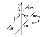
図2は、スリップ角−SATモデルのスリップ角基準値の上限と下限とを表したものであり、各々の境界を表す直線の傾きはK2である。この直線の傾きK2は、高グリップ状態で操舵した時に生じるSATと前輪スリップ角との関係を表している。また、上限と下限の間の幅はヒステリシス特性の大きさを表しており、2直線の横軸上の間隔は、クーロン摩擦によって生じる摩擦トルクTfricを表している。
【0074】
また、この傾きK2は、走行する車速に応じて変化させることにより、より精密に摩擦状態を推定することができる。さらに、この傾きK2は、装着したタイヤ種別によっても変更することが望まれるものであり、スタッドレスタイヤやサマータイヤ等の種別が判別している場合には、タイヤ種別に応じて変更しても良い。
【0075】
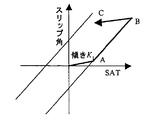
図3は、スリップ角基準値の演算方法を示すものである。直進状態では、SATは0であり、このときのスリップ角基準値として0を出力する。次に操舵が行われ、SATが発生した場合、スリップ角基準値は、SATに対し傾きK1の直線に基づいて演算される。コンピュータ内では、離散化されたロジックにより、以下の式に基づいて演算される。
【0076】
【数10】
![]()
ただし、α0は、スリップ角基準値であり、kは時刻を表している。この傾きK1は、K2に比較して小さく設定されており、クーロン摩擦等によってSATが変動しても発生するスリップ角の変動を小さくすることを表現している。さらに、操舵が行われ、(14)式によるスリップ角基準値の演算値が図3におけるA点まで達し、さらにSATが増加する場合には、スリップ角基準値はスリップ角−SATモデルの下限を表す直線に沿って次式に従って増加する。
【0078】
【数11】
![]()
また、さらに操舵が行われてB点まで達したところで切り増しが終了し、SATが減少し始めた場合には、スリップ角基準値は傾きK1で(14)式に従って減少する。この領域では、SATの変動に対し、スリップ角基準値の変動は小さくなるように設定されている。これは、旋回時の保舵状態においてドライバの操舵力を多少変化させてもパワーステアリング装置のクーロン摩擦等の影響によって舵角や前輪スリップ角には影響が現れないことを表現したものである。
【0080】
なお、B点からSATの減少によって到達したC点において再びSATが増加する場合には、スリップ角基準値は(14)式に従いB点に向かって増加する。また、切戻しによりC点からさらにSATが減少し、スリップ角−SATモデルの上限に達した場合には、スリップ角基準値は上限を表す直線に沿って(15)式に従って減少する。このように各領域によって異なる2種類の傾きK1、K2を有する演算式によって図3に示すヒステリシス特性が実現され、高グリップ状態、すなわち高μ路面走行等グリップ状態に十分な余裕のある状態を仮定したときの前輪スリップ角がSATの時系列信号から推定できる。したがって、スリップ角基準値は、グリップ状態が十分に高く余裕がある操舵領域において発生する前輪のスリップ角をSAT推定値から演算したものになる。また、スリップ角基準値は、グリップ状態が充分に高く余裕がある操舵領域において発生する前輪のスリップ角であるので、セルフアライニングトルクの推定値に対するヒステリシス特性が除去されている。
【0081】
摩擦状態推定手段40は、スリップ角推定手段34によって推定された前輪スリップ角の推定値とスリップ角基準値演算手段によって演算されたスリップ角基準値とを比較し、グリップ状態が低下する程、スリップ角基準値に比較してスリップ角が大きくなることを利用してグリップ状態、すなわち路面摩擦状態を演算する。
【0082】
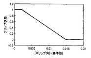
グリップ状態(路面摩擦状態)は、前輪スリップ角の絶対値とスリップ角基準値の絶対値との差を用いて、図11に示すマップから演算することができる。ここで演算されるグリップ状態は、[0、1]の範囲で基準化されたものであり、大きい程グリップが高いことを表している。図11に示すマップから前輪スリップ角の絶対値とスリップ角基準値の絶対値との差が大きくなるに従って、グリップ状態、すなわち路面摩擦状態は小さく推定され、前輪スリップ角の絶対値とスリップ角基準値の絶対値との差が小さくなるに従って、グリップ状態、すなわち路面摩擦状態は大きく推定される。なお、この偏差に代えて、前輪スリップ角の絶対値とスリップ角基準値の絶対値との比を用いて路面摩擦状態を推定してもよい。
【0083】
ここで、低μ路走行時等のグリップ状態が低下した状態で操舵が行われた場合には、前輪スリップ角の微小変化にSAT推定値の微小変化の比で表される傾き(スリップ角−SAT曲線のスリップ角が所定値の点における接線の傾き)は、図4に示すように、高グリップ状態と比較して小さくなる。このため、図3とは逆に、SATを横軸、前輪スリップ角を縦軸に記述した場合には、図5に示すように、高グリップ状態を仮定したスリップ角基準値と比較すると低グリップ状態の前輪スリップ角は大きくなり、SATの前輪スリップ角に対する傾きはグリップ状態が小さくなるに従って大きくなる。スリップ角基準値は、グリップ状態が十分に高く余裕がある操舵領域において発生する前輪のスリップ角をSATから演算したものであるので、この特性を利用して、前輪スリップ角とスリップ角基準値とを比較することによりグリップ状態の低下を判別することが可能となる。なお、上記で説明したように前輪スリップ角とスリップ角基準値との偏差をそのままグリップ低下の指標として利用しても良いが、スリップ角基準値に対して、車速、タイヤ種別、または制駆動等の状態に応じた重み付けを行い、基準化して用いても良い。
【0084】
本実施の形態では、SATの時系列信号から高グリップ状態におけるスリップ角を推定するモデルを用い、このモデルの出力であるスリップ角基準値と実際の前輪スリップ角(舵角から推定)とを比較することによってグリップ状態を判定している。このモデルは、ヒステリシス特性が考慮されたものとなっており、例えば保舵時にハンドルが動かない程度にドライバが操舵力を減少させた場合でも、モデル出力であるスリップ角基準値は大きく落ち込まないモデルとなっている。このため、ドライバの操舵力が変動する保舵状態においてもスリップ角基準値と前輪スリップ角推定値を比較することによってグリップ状態を推定することができる。
【0085】
第1の実施の形態は、従来技術と同様にSATとスリップ角との物理的関係を利用して路面摩擦状態を推定するものであるが、逆にスリップ角からSATの基準値をスリップ角−SATモデルによって演算し、SATの基準値と実際のSAT(SAT推定値)とを比較することによってグリップ状態を含む路面摩擦状態を推定することも考えられる。
【0086】
しかしながら、前述のように実際のSATは、保舵状態においてドライバの操舵力変動の影響を大きく受ける。このため、誤差要因の大きなSATをモデル出力と比較する構成では、推定誤差が大きく、保舵時の推定は従来技術と同様に困難となる。
【0087】
これに対し、本第1の実施の形態では保舵時に変動の小さなスリップ角に着目し、スリップ角とスリップ角基準値との比較を行っているため、保舵時や切り戻し時においても正確にグリップ状態を含む路面摩擦状態を推定することが可能となっている。
【0088】
また、切戻しや保舵時に推定できるということは、例えば、保舵状態で低μ路から高μ路へ乗り移ったり、高μ路から低μ路に乗り移ったりしてグリップ状態が変化する場合に、推定遅れが生じることなく変化した時点で推定できることを意味している。このため、従来技術では不可能であった速い適応性が要求されるパワーステアリング装置やABSの特性をグリップ状態に応じて切り替える制御パラメータとして利用することも可能である。
【0089】
次に、上記第1の実施の形態による路面摩擦状態の推定の実験結果について説明する。上記で説明したように、スリップ角推定手段34では、車両運動の動特性を利用し、上記(3)、(4)式に基づいて前輪のスリップ角が推定される。SAT推定手段36では、ハンドルと同軸上に取り付けられたトルクセンサ20によって計測された操舵トルクと、電動パワーステアリング装置の電流から演算されるアシストトルクとを加算し、さらにパワーステアリング装置の粘性摩擦を考慮し、操舵速度を用いて(6)式に基づいてSATが推定される。
【0090】
図6は、高μ路を30km/hで走行中に操舵を行ったときの(3)、(4)式によって演算された前輪スリップ角と(6)式によって演算されたSAT推定値との関係を示したものである。図6には、高グリップ状態で操舵した時に生じるSATと前輪スリップ角との関係に対応するスリップ角基準値の上下限(図2参照)を示す直線を同時に破線で示している。
【0091】
また、図7に同じ実験結果を用い、操舵角と粘性を考慮しない(5)式に基づいて演算されたSATとの関係を示す。操舵角の代わりにタイヤ発生力の基本的な状態量であるスリップ角を用いると共にパワーステアリング装置で発生する粘性摩擦を考慮してSATを求めることによって、再現性良く破線上(上下限を示す直線)を通ることがわかる。この特性は、グリップ状態を含む路面摩擦状態の推定の基礎になるものであり、図7と比較して推定精度が向上することが期待できる。
【0092】
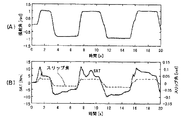
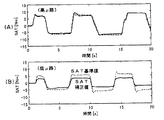
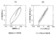
また、図8(A)、(B)は、この実験結果の時間応答(SATは、粘性補償を行った値)を示したものである。この実験では、図8(A)に示すように操舵と保舵とを繰り返すステップ操舵が行われており、このときの前輪スリップ角推定値は、操舵角に応じてステップ的な波形となっている。これに対し、SATは、図8(B)に示すように保舵中に減少しており、また減少時の波形には再現性が見られない。これは、保舵中のドライバの操舵力が変動していることを表しており、SATをモデル出力と比較する手法では、変動の影響を受けて正確なグリップ状態の推定が困難であることが予測できる。
【0093】
これに対し、保舵中のスリップ角の波形は安定しており、スリップ角をモデル出力(スリップ角基準値)と比較する本実施の形態では保舵中においても正確にグリップ状態の推定が可能となることが理解できる。
【0094】
スリップ角基準値演算手段38では、SAT推定手段36によって推定されたSAT推定値からパワーステアリング装置のクーロン摩擦等によって生じるヒステリシス特性を考慮したスリップ角の基準値が演算される。まず、操舵角が0で、SATが0となる直進状態において、スリップ角基準値の初期値を0に設定する。次いで、操舵が開始され、SATが出力されると(14)、(15)式の漸化式に従ってスリップ角基準値が演算される。ここで、高グリップ状態で操舵した時に生じるSATと前輪スリップ角との関係を表す傾きK2は、車速に応じて変化するように設定している。図9は、図8(B)のSATから上記アルゴリズムによってスリップ角基準値を演算した結果と前輪スリップ角推定値とを比較して示したものである。ヒステリシス特性を考慮したアルゴリズムによって、モデルの入力であるSATの波形は保舵時に減少や振動的な特性を有しているにもかかわらず、出力であるスリップ角基準値は略一定の値となっている。また、この実験が行われた高μ路においては、スリップ角基準値はスリップ角推定値と良い一致が見られることがわかる。
【0095】
図10は、図9と同様の実験をグリップ状態の低下する低μ路において実施した結果を示したものである。この実験では図9と略同様の舵角の操舵が行われており、スリップ角推定値は図9と同様の出力が得られているにもかかわらず、SATから演算されるスリップ角の基準値は小さく、SATの推定値とSATの基準値との間には偏差が生じていることがわかる。これは、グリップ状態の低下により、高グリップ状態を仮定したスリップ角基準値と比較して実際の前輪スリップ角が大きくなるために生じたものである。
【0096】
摩擦状態推定手段40では、スリップ角推定手段34によって推定された前輪スリップ角とスリップ角基準値演算手段38によって演算されたスリップ角基準値とを比較し、グリップ状態が演算される。グリップ状態は、前輪スリップ角の絶対値とスリップ角基準値の絶対値との差を用いて、図11に示すマップから演算する。ここで演算されるグリップ状態は、[0、1]の範囲で基準化されたものであり、大きい程グリップが高いことを表している。図11に示すマップから前輪スリップ角の絶対値とスリップ角基準値の絶対値との差が大きくなるに従って、グリップ状態、すなわち路面摩擦状態は小さく推定され、前輪スリップ角の絶対値とスリップ角基準値の絶対値との差が小さくなるに従って、グリップ状態、すなわち路面摩擦状態は大きく推定される。
【0097】
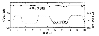
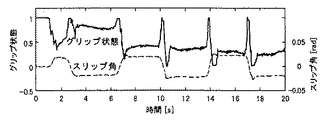
図12は、高μ路走行時のグリップ状態とスリップ角推定値とを示すものである。高μ路走行時には、この程度のスリップ角では、スリップ角の有無に関わらず常に高いグリップ状態となっていることが推定できている。図13は、低μ路走行時における図12と同様のグリップ状態とスリップ角推定値とを示している。低μ路走行時には、グリップ状態が低下していることが理解できる。また、操舵中にスリップ角が0付近になる時点でグリップ状態は1となり、直進に近い領域ではグリップが回復する現象が正確に推定できていることが理解できる。
【0098】
次に、SAT推定値に生じるヒステリシス特性の原因となる摩擦トルクTfricの推定について説明する。ここでは、ハンドル切り増し中に絶対値が最大となったときのSAT推定値とハンドル切り戻し時点のSAT推定値との差を演算し、この差を操舵系の内部クーロン摩擦によって生じる摩擦トルクTfricとして推定する。
【0099】
ハンドルを左方向に操舵した時に生じるSAT推定値TSATを正、ハンドルを右方向に操舵した時に生じるSAT推定値TSATを負とし、操舵角速度センサから供給された操舵角速度信号の符号が反転したことを検出すると、このタイミング以降のSAT推定値TSATの最大値を次のように演算する。
【0100】
操舵角速度信号が負から正に反転して、ハンドルが左方向(正方向)に操舵された場合、正のSAT推定値TSATが発生するので、SAT推定値TSATの最大値Tmaxを以下の式に従って演算する。
【0101】
【数12】
次に、操舵の切り戻しによって操舵角速度が正から負に反転したことを検出すると、この時点のSAT推定値TSATと上記のように求められた最大値Tmaxとを用いて、下記式に従って摩擦トルクTfricを演算する。
【0103】
【数13】
一方、操舵角速度が正から負に反転して、ハンドルが右方向に操舵された場合、負のSAT推定値TSATが発生するので、次式に従って、SAT推定値TSATの最小値Tminを演算する。
【0105】
【数14】
次に、操舵の切り戻しによって操舵角速度が負から正に反転したことを検出すると、この時点のSAT推定値TSATと上記のように求めた最小値Tminとを用いて、次式に従って摩擦トルクTfricを演算する。
【0107】
【数15】
![]()
この結果、ハンドルの切り戻しのたびに生じるヒステリシス特性に対して、ハンドル切り戻しの度に摩擦トルクTfricが推定されるので、常に正確なヒステリシス特性の大きさを推定することができる。
【0109】
特に悪路走行時には、路面外乱が操舵系内部のクーロン摩擦に対してディザー効果として働き、クーロン摩擦項が減少してクーロン摩擦が変化する。そこで、上述のようにハンドル切り戻しの度に摩擦トルクTfricを推定すれば、クーロン摩擦の大きさが変化する場合においても、逐次最新のヒステリシス特性の補償を行うことができる。
【0110】
第1の実施の形態では、SATからスリップ角を求めるモデルを用い、ヒステリシス特性を有するSATを入力としたときのモデル出力であるスリップ角基準値を求めることによりヒステリシス特性を除去し、スリップ角基準値とスリップ角の推定値との比較によってグリップ状態を推定する例について説明した。以下で説明する第2の実施の形態は、ヒステリシス特性を有するSATから直接ヒステリシス特性を除去し、ヒステリシス特性を除去したSAT補正値とスリップ角とからグリップ状態を路面摩擦状態として推定するものである。
【0111】
本実施の形態を図14を参照して説明する。本実施の形態は、マイクロコンピュータを機能ブロックで考えたときの図1に示すスリップ角基準演算手段に代えて、SATからヒステリシス特性を除去するヒステリシス特性除去手段42を設け、摩擦状態推定手段44において、ヒステリシス特性を除去したSAT補正値とスリップ角推定手段34で推定されたスリップ角の推定値とに基づいてグリップ状態を含む路面摩擦状態を推定するようにしたものである。
【0112】
以下、各手段の作用について説明する。ヒステリシス特性除去手段42は、SAT推定手段36において推定されたヒステリシス特性を有するSAT推定値からヒステリシス特性発生の原因となるパワーステアリング装置のクーロン摩擦等の影響を除去し、ヒステリシス特性の無いSAT推定値をSAT補正値として出力する。
【0113】
摩擦状態推定手段44は、スリップ角とヒステリシス特性を除去したSAT補正値とから以下のようにしてグリップ状態を路面摩擦状態として演算し出力する。
【0114】
ヒステリシス特性除去手段42によるヒステリシス特性除去の演算は、以下のロジックによって行われる。このロジックは、SAT推定値の変化に対するSAT補正値の変化の比で表される傾きを有する演算式であって、クーロン摩擦によってSAT推定値が変動する領域の傾きK1をこの領域以外の領域の傾き(=1)より小さくした各領域毎に異なる演算式によって演算するものである。
【0115】
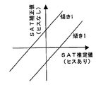
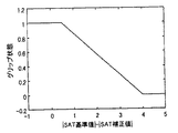
図15は、ヒステリシス特性を有するSAT推定値とヒステリシス特性を除去したSAT推定値(SAT補正値)との関係を示す座標面であり、座標面上の2本の直線の幅は、ヒステリシス特性の大きさを表したものである。ヒステリシス特性を有するSAT推定値とヒステリシス特性を除去したSAT推定値とは、ヒステリシス特性分だけ大きさが相違しているだけであるので、各々の直線の傾きは1である。
【0116】
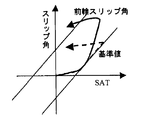
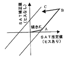
図16は、ヒステリシス特性除去演算の方法を示すものである。SAT推定値及びスリップ角共に0となる直進状態では、ヒステリシス特性は発生しておらず、このときのSAT補正値は0を出力する。次に操舵が行われ、SATが発生した場合、SAT補正値は、SAT推定値に対しK1の傾きで演算される。コンピュータ内では、離散化されたロジックにより、以下に示す(16)式に従って演算される。
【0117】
【数16】
![]()
ただし、TSAT0は、ヒステリシス特性を除去したSAT補正値である。この傾きK1は、1に比較して小さく設定されており、クーロン摩擦等によってSAT推定値が変動してもSAT補正値の変動は小さくなるようにされている。
【0119】
上記(16)式は、セルフアライニングトルク推定値の現在値、セルフアライニングトルク推定値の前回値、及びセルフアライニングトルク補正値の前回値からセルフアライニングトルク推定値の現在値がクーロン摩擦によるヒステリシス領域内にあるか否かを判断し、ヒステリシス領域内にある場合には、セルフアライニングトルク補正値の現在値とセルフアライニングトルク補正値の前回値との差によって演算される補正値変化の大きさが、セルフアライニングトルク推定値の現在値とセルフアライニングトルク推定値の前回値との差によって演算される推定値変化の大きさより小さくなり、ヒステリシス領域外にある場合には、補正値変化と推定値変化とが一致するようにセルフアライニングトルク補正値の現在値を演算することを表している。
【0120】
さらに、操舵が行われ、(16)式によるSAT補正値の演算値が図16におけるA点まで達し、さらにSAT推定値が増加する場合には、SAT補正値は、モデルの下限を示す直線に沿って次式に従って増加する。
【0121】
【数17】
![]()
また、さらに操舵が行われてB点まで達したところで切り増しが終了し、SAT推定値が減少し始めた場合には、傾きK1で(16)式に従ってSAT補正値は減少する。この領域では、SAT推定値の変動に対し、SAT補正値の変動は小さくなるように設定されている。これは、旋回時の保舵状態においてドライバの操舵力を多少変化させてもパワーステアリング装置のクーロン摩擦等の影響によってSAT補正値には影響が現れないようにしたものである。なお、B点からSATの減少によって到達したC点において再びSAT推定値が増加する場合には、(16)式に従いB点に向かってSAT補正値は増加するように演算される。また、切戻しによりC点からさらにSAT推定値が減少し、モデル上限に達した場合には、SAT補正値は上限を示す直線に沿って(17)式に従って減少するように演算される。このような2種類の傾きの設定によってSAT推定値に対するSAT補正値は一義的に定まり、図16に示すヒステリシス特性が除去される。
【0123】
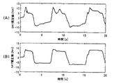
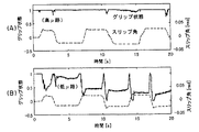
図17(A)は、高μ路面走行時のSAT推定値、図17(B)はこのSAT推定値から(16)、(17)式に基づいてヒステリシス特性を除去したSAT補正値を各々示したものである。図17(A)、(B)の比較によりヒステリシス除去の効果によって、クーロン摩擦等の影響と考えられる保舵時の変動が略補償されていることがわかる。
【0124】
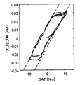
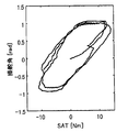
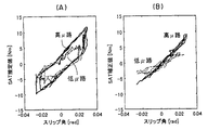
また、図18(A)は、高μ路、低μ路走行時のスリップ角とSAT推定値との関係、図18(B)は、スリップ角とSAT補正値との関係を各々示したものである。図18(B)からスリップ角とSAT補正値との関係は略線形になっており、ヒステリシス特性が除去されていることが理解できる。
【0125】
路面摩擦状態推定手段44は、スリップ角推定手段34によって推定された前輪スリップ角とヒステリシス特性が除去されたSAT補正値とに基づいてグリップ状態を路面摩擦状態として以下に示すように演算する。
【0126】
すなわち、路面摩擦状態推定手段44では、スリップ角に車速やタイヤ種別に応じて変化する係数を乗じて導出されたSAT基準値と、SAT補正値とを比較し、SAT基準値とSAT補正値と差に応じてグリップ状態を出力する。SAT基準値を導出するための係数は高グリップ状態を仮定して設定するものであり、低μ路走行時等低グリップ状態時にはSAT補正値はSAT基準値に比較して小さくなる。路面摩擦状態推定手段44では、この性質を利用し、SAT基準値の絶対値とSAT補正値の絶対値との偏差が大きい程グリップ状態、すなわち路面摩擦状態は小さくなるように演算して出力する。
【0127】
図19(A)、(B)は、SAT補正値(実線)と車速に応じて変化する係数を前輪スリップ角に乗じて導出されたSAT基準値(破線)とを比較したものである。高グリップ状態を仮定してスリップ角から演算されたSAT基準値は、図19(A)に示すように、高μ路走行時にはSAT補正値と略一致するのに対し、グリップ状態が低下する低μ路走行時には、図19(B)に示すように、SAT補正値との間に偏差が生じていることが理解できる。
【0128】
従って、路面摩擦状態推定手段44では、SAT補正値及びSAT基準値各々の絶対値の差を用いて、図20に示すマップからグリップ状態を含む路面摩擦状態を演算する。ここで演算されるグリップ状態を含む路面摩擦状態は、[0、1]の範囲で基準化されたものであり、大きいほどグリップ状態、すなわち路面摩擦状態が高いことを表している。図20に示すマップからSAT基準値の絶対値とSAT補正値の絶対値との差が大きくなるに従って、グリップ状態、すなわち路面摩擦状態は小さく推定され、SAT基準値の絶対値とSAT補正値の絶対値との差が小さくなるに従って、グリップ状態、すなわち路面摩擦状態は大きく推定される。
【0129】
図21(A)、(B)は、高μ路走行時のグリップ状態とスリップ角推定値、低μ路走行時のグリップ状態とスリップ角推定値を各々示している。図21(A)に示すように、高μ路走行時には、この程度のスリップ角では、スリップ角の有無に関わらず常に高いグリップ状態となっていることが推定できている。また、図21(B)に示すように、低μ路走行時には、グリップ状態が低下していることが理解できる。また、操舵中にスリップ角が0付近になる時点でグリップ状態は1となり、直進に近い領域ではグリップ状態が回復する現象が正確に推定できていることが理解できる。
【0130】
第1の実施の形態ではスリップ角のモデルとの比較によって、また第2の実施の形態では、SATのモデルとの比較によって、各々グリップ状態を含む路面摩擦状態を推定する例について説明したが、本発明はこのようにモデルとの比較という構成に限られるものではなく、ヒステリシス除去後のSATとスリップ角の関数としてグリップ状態を記述したり、ヒステリシス除去後のSATとスリップ角の2次元マップでグリップ状態を含む路面摩擦状態を推定しても良い。
【0131】
また、上記では本発明を電動パワーステアリング装置を搭載した車両へ適用した例について説明したが、操舵トルクとアシストトルクとに対応するパワーステアリング装置の油圧が計測できれば、本発明は油圧パワーステアリング装置の車両にも適用できるものである。
【0132】
次に、本発明を操舵角中立点推定装置に適用した第3の実施の形態について説明する。本実施の形態は、第2の実施の形態のヒステリシス特性除去手段を用いて車両が直進状態となるハンドルの操舵角である中立点の位置を推定するものである。
【0133】
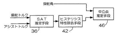
以下、本実施の形態を図22を参照して説明する。本実施の形態は、図14のスリップ角演算手段34を省略し、摩擦状態推定手段44に代えて中立点推定手段46を設け、中立点推定手段46によって操舵角とヒステリシス特性を持たないSAT推定値であるSAT補正値とにより中立点の位置を推定するようにしたものである。なお、図22において図14と対応する部分には、同一符号を付して詳細な説明は省略する。
【0134】
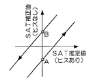
以下、各手段の作用について説明する。ヒステリシス特性除去手段42は、上記で説明したようにSAT推定手段36において推定されたヒステリシス特性を有するSAT推定値からヒステリシス特性発生の原因となるパワーステアリング装置のクーロン摩擦等の影響を除去し、ヒステリシス特性を持たないSAT推定値をSAT補正値として出力する。すなわち、図23に示すように、横軸にヒステリシス特性を持つ場合のSAT推定値、縦軸にヒステリシス特性を持たない場合のSAT推定値をとって表した場合、ヒステリシス特性を持つSAT推定値が負の値から0になり(右操舵時に発生するトルクを正とする場合)、かつ操舵角速度が一定値以上の正の値を示した場合(右操舵を正とする場合)には、図23に示すA点を通る傾き1の直線を用い、A点を初期値として上記の第2の実施の形態の図16で説明したのと同様のアルゴリズムによってヒステリシス特性を除去したSAT補正値を演算する。
【0135】
また、ヒステリシス特性を持つSAT推定値が正の値から0になり、かつ操舵角速度が一定値以下の負の値を示した場合、図23に示すB点を通る傾き1の直線を用い、B点を初期値として上記の第2の実施の形態の図16で説明したのと同様のアルゴリズムによってヒステリシス特性を除去したSAT補正値を演算する。
【0136】
中立点推定手段46は、ヒステリシス特性が除去されたSAT補正値が0となるときの操舵角を中立点として出力する。
【0137】
操舵角とSATまたは操舵トルクとの間には、ヒステリシス特性が存在する(ヒステリシス特性を持っている)ため、従来の中立点は、操舵角の頻度から統計的に推定するのが一般的であった。しかしながら、従来の統計的方法では、使用するデータ量が多いため推定を完了するまでに長時間を要したり、周回するコースを走行する場合には、操舵角の偏りから推定誤差が生じる等の問題がある。これに対し、本実施の形態では、ヒステリシス特性除去後のSAT推定値と操舵角との関係から中立点を推定しているため、精度良くかつ容易に中立点を推定することが可能となり、統計的な処理を行なうことなく短時間に、かつ操舵角の偏りの影響も受けずに中立点を推定することができる。
【0138】
次に、本発明の第4の実施の形態について説明する。本実施の形態は、第2の実施の形態のヒステリシス特性除去手段を用いてハンドル操舵時の粘性を推定するようにしたものである。本実施の形態は、図24に示すように、図14の摩擦状態推定手段44に代えて、オンライン同定手段48を用い、オンライン同定手段48に更に操舵角速度を示す信号を入力してハンドル操舵時の粘性を推定するようにしたものである。なお、図24において図14と対応する部分には、同一符号を付して詳細な説明は省略する。
【0139】
オンライン同定手段48は、上記で説明したアルゴリズムでヒステリシス特性が除去されたヒステリシス特性除去後のSAT推定値、スリップ角演算手段34で演算されたスリップ角、及び操舵角速度に基づいて、オンライン同定手法を適用してハンドルの粘性を推定する。
【0140】
本実施の形態では、ヒステリシス特性除去後のSAT推定値(SAT補正値)を用いてハンドルの粘性を推定しているので、クーロン摩擦等によって生じるヒステリシス特性が除去され、ハンドル粘性の推定精度を向上することができる。
【0141】
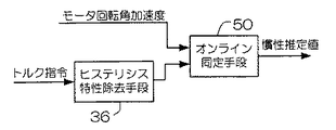
上記で説明したヒステリシス特性除去手段は、ハンドルのクーロン摩擦等によって発生するヒステリシス特性を除去する場合に限定されるものではなく、クーロン摩擦等を含む多くのシステムに応用可能である。例えば、作業中のロボットの手先負荷の慣性をオンラインで推定する場合等にも適用することができる。図25は、手先負荷の慣性をオンラインで推定する場合の構成を示したものであり、ヒステリシス特性除去手段36は、上記で説明したアルゴリズムでモータへの指令トルクからクーロン摩擦分を除去したモータ出力トルクTを推定する。また、オンライン同定手段50は、モータの回転角速度αの時系列信号とヒステリシス特性除去手段36から出力される出力トルクTの時系列信号とから、慣性J、モータの回転角速度α、及び出力トルクTの関係を示す式Jα=Tに基づいてオンライン同定手法を適用することによって、慣性Jを推定する。
【0142】
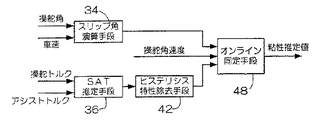
次に、図26を参照して空気圧の低下を判定する第5の実施の形態について説明する。本実施の形態は、図14で説明したように、操舵トルクとアシストトルクとを加算してSAT推定値を演算するSAT推定手段36、SAT推定値から操舵系の摩擦によって生じるヒステリシス特性を除去し、路面−タイヤ間で発生しているSATをSAT補正値として推定するSAT補正手段42、操舵角と車速に基づいて前輪のスリップ角を推定するスリップ角推定手段34が設けられている。本実施の形態では、図14の摩擦状態推定手段に代えてSAT補正値と前輪スリップ角とに基づいて空気圧の低下を判定する空気圧低下判定手段50が設けられている。
【0143】
次に、空気圧低下判定手段50による空気圧低下の推定原理について説明する。タイヤ発生力特性を理論的に記述したブラッシュモデルによると、サイドフォースFfy及セルフアライニングトルク(SAT)Tsは、以下の式で表される。
【0144】
【数18】
ただし、
【0146】
【数19】
である。
【0148】
ここで、
Fz:接地荷重、
l:タイヤ接地長、
Ky:単位幅かつ単位長さ当たりのトレッドラバーの横方向剛性、
b:接地面の幅、
λ:横スリップ、
である。
【0149】
この横スリップλと前輪スリップ角との間には、
【0150】
【数20】
![]()
の関係が有るが、一般的にξ>0の領域ではスリップ角αfは小さいので、下記の(22)式のようにみなすことができる。
【0152】
【数21】
![]()
以上の関係からスリップ角0付近におけるスリップ角の微小変化に対するサイドフォースの微小変化の比∂Ffy/∂αfで表される勾配(以下、サイドフォース勾配という)、及びスリップ角の微小変化に対するSAT補正値の微小変化の比で表される勾配∂Ts/∂αf(以下、SAT補正値の勾配という)は、各々以下のように表される。
【0154】
【数22】
ここで、空気圧が低下すると、路面に対するタイヤの接地長が増加するので、サイドフォース勾配、またはSAT補正値の勾配を演算し、サイドフォース勾配、またはSAT補正値の勾配が増加したか否かを判断することにより、タイヤの空気圧低下を判断することができる。本実施の形態の空気圧低下判定装置は、この特徴に着目し、空気圧低下に伴う接地長の増加をサイドフォース勾配の増加またはSAT補正値の勾配の増加として検出するものである。
【0156】
なお、上記(23)式、(24)式より、サイドフォース勾配はタイヤ接地長の2乗に比例するのに対し、SAT勾配はタイヤ接地長の3乗に比例し、SAT勾配の方がタイヤ接地長の変化がより顕著に表れるので、空気圧の低下をより精度良く検出することができる。
【0157】
以下、本実施の形態の作用について説明する。本実施の形態は、SAT勾配に基づいて、空気圧の低下を判定するようにしたものである。SAT推定手段36は、図14で説明したのと同様に、操舵トルクとアシストトルクとを加算してSAT推定値を演算する。ここで推定されたSAT推定値は、操舵系の内部摩擦を含んだ値であるので、SAT補正手段42は、SAT推定値から操舵系の摩擦によって生じるヒステリシス特性を除去し、路面−タイヤ間で発生している実際のSATをSAT補正値として推定する。また、スリップ角推定手段34は、図14で説明したように、操舵角と車速とに基づいて前輪のスリップ角を推定する。
【0158】
空気圧低下判定手段50は、上記で説明した推定原理に基づいて、上記で説明した空気圧低下に伴う接地長の増加をSAT補正値の勾配の増加として検出する。すなわち、空気圧低下判定手段50は、前輪スリップ角とSAT補正値とからスリップ角に対するSAT補正値の勾配を演算し、このSAT補正値の勾配が一定値以上になった場合に、空気圧が低下したと判定する。
【0159】
このSAT補正値の勾配は、上記で説明したオンライン同定法(オンライン最小2乗法)を用いて推定演算することができる。このオンライン最小2乗法は、以下で説明する図27(B)のSAT補正値の勾配を推定し、推定された勾配と一定値(基準勾配を表す一点鎖線の勾配)との比較を行うものである。
【0160】
このオンライン最小2乗法を用いる場合、直進付近の微小な操舵状態においても勾配を推定することが可能であるため、直進に近い走行条件でも空気圧低下の判定が可能となる。また、SAT補正値の勾配のみに着目するため、バンク走行時等路面カントによるSAT特性の切片がずれる状況においても路面カントの影響を受けることなく正確に空気圧低下の判定ができると、いう効果が得られる。
【0161】
なお、本実施の形態では、SAT補正値の勾配を用いて空気圧の低下を判定する例について説明したが、本実施の形態はこれに限定されるものではなく、上記の第2の実施の形態で用いた前輪スリップ角に応じて設定されるSAT基準値を用い、このSAT基準値とSAT補正値とを比較し、SAT補正値がSAT基準値より大きくなった場合に、タイヤの空気圧が低下したと判定するようにしてもよい。すなわち、空気圧低下判定手段50では、SAT補正値とSAT基準値との差を演算し、この差が閾値を越えた場合に空気圧の低下と判定したり、またはSAT補正値とSAT基準値との比を演算し、この値が閾値を超えた場合に空気圧が低下したと判定してもよい。また、ここで用いられる閾値は、スリップ角や車速に応じて可変に設定しても良い。
【0162】
図27(A)は、空気圧が正常の状態で一定車速(30km/h)で走行中に、ステップ操舵を繰り返した時の操舵角とSAT推定値との関係、すなわち操舵角とドライバの操舵する操舵トルクにパワーステアリングのアシストトルクを加算した値との関係を示したものである。
【0163】
特開平11−59466号公報及び特開平11−334634号公報に記載された従来技術では、一点差線で示す基準トルクを設定し、SAT推定値が基準トルクを超えた場合に空気圧が低下したと判定している。しかしながら、図27(A)に示すように操舵角とSAT推定値との間にはヒステリシス特性が存在しているので、空気圧が正常にも拘わらず、操舵の過渡時等では基準値を超えている。
【0164】
従来技術では、空気圧低下判定を保舵時に限定する等によってこのような過渡状態における誤作動の防止を図っているが、この対策は推定できる走行条件を限定するものであり、判定遅れ等の問題が生じるものである。
【0165】
これに対し本実施の形態では、SAT推定値及びSAT基準値を用いる場合には、図27(B)に示すように、横軸を図27(A)の操舵角に代えてスリップ角としている。スリップ角は、タイヤの横力発生の基になる物理量であり、スリップ角とSATとの間には時間遅れ等の動特性が存在しない。これに対し、操舵角とSATとの間には、操舵角とスリップ角の間に車両運動に伴う動特性が存在するため、この動特性の影響を受ける。
【0166】
本実施の形態では、横軸を車両運動の動特性の影響を受けないスリップ角としているため、過渡時においても空気圧低下判定を行うことができる。
【0167】
図27(B)は、上記のように横軸をスリップ角としたときのSAT推定値(破線)と操舵系の摩擦を除去したSAT補正値(実線)との変化を示したものである。横軸をスリップ角とすることで、車両運動の動特性の影響による特性のふくらみが除去され直線的な特性が得られていることが理解できる。
【0168】
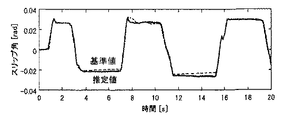
さらに、SAT補正手段42において操舵系の摩擦を除去することによって、ヒステリシス特性も除かれていることが理解できる。図27(B)には、同時に本実施の形態の空気圧低下判定手段50において設定されたSAT基準値を一点鎖線で示している。この実験では、原点近傍の領域を除きSAT補正値が常にSAT基準値以下となっており、直進状態を除く広い領域で空気圧の低下判定が精度良く行われていることが理解できる。
【0169】
次に、図28を参照して本発明の第6実施の形態を説明する。本実施の形態は、図5の実施の形態のスリップ角推定手段52に代えて、横加速度を検出する横加速度センサ44、ヨー角速度を検出するヨー角速度センサ46、及び横加速度とヨー角速度とに基づいて、前輪のサイドフォースを推定するサイドフォース推定手段52を設けたものである。
【0170】
SAT推定手段26は、上記で説明したように、操舵トルクとアシストトルクを加算してSAT推定値を演算する。ここで推定されたSAT推定値は、操舵系の内部摩擦を含んだ値であるので、SAT補正手段42は、SAT推定値から操舵系の摩擦によって生じるヒステリシス特性を除去し、路面−タイヤ間で発生している実際のSATをSAT補正値として推定する。
【0171】
サイドフォース推定手段52は、横加速度センサ44で検出された横加速度とヨー角速度センサ46で検出されたヨー角速度とに基づいて、前輪のサイドフォースを推定する。空気圧低下判定手段54は、SAT補正値と前輪サイドフォースとに基づいて空気圧の低下を判定する。
【0172】
ここで、前輪サイドフォース(横力)Ffは、以下の式で示される車体の運動方程式から求めることができる。
【0173】
【数23】
ただし、前輪サイドフォースFfは、(25)、(26)式を連立し、後輪サイドフォースFrを消去することによって、以下の(27)式のように表すことができる。
【0175】
【数24】
ただし、
【0177】
【数25】
である。
【0179】
また、M、v、r、u、Iz、Lf、Lr、は、上記(1)、(2)式で説明したのと同じ物理量であり、 Ffは前輪サイドフォース、Frは後輪サイドフォースである。
【0180】
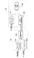
したがって、サイドフォース推定手段52は、図29に示すように、(27)式に基づいてヨー角速度にハイパスまたはバンドパスフィルタ処理を施して近似演算したヨー角速度微分値dr/dtに近似した値を出力するフィルタ52B、横加速度信号にヨー角速度に施したフィルタ処理と同じカットオフ周波数でローパスフィルタ処理を施して近似演算した横加速度微分値dv/dtに近似した値を出力するローパスフィルタ52A、及びローパスフィルタ52A出力とフィルタ52B出力とから上記(27)式に基づいて前輪のサイドフォースFrを推定する演算手段52Cから構成されている。
【0181】
また、空気圧低下判定手段54は、前輪サイドフォースに応じたSAT基準値を設定するSAT基準値設定手段54B、ヨー角速度に施したフィルタ処理と同じカットオフ周波数でSAT補正値に対してローパスフィルタ処理を施すローパスフィルタ54A、及び前輪サイドフォースに応じて設定されたSAT基準値とローパスフィルタ54Aでローパスフィルタ処理されたSAT補正値とを比較し、SAT補正値がSAT基準値より大きくなった場合に、空気圧が低下したと判定する比較手段54Cから構成されている。
【0182】
比較手段54Cでは、SAT補正値とSAT基準値の差を演算し、この差が閾値を越えた場合に空気圧が低下したと判定したり、SAT補正値とSAT基準値との比を演算し、この比の値が閾値を超えた場合に空気圧が低下したと判定することができる。また、ここで用いられる閾値はスリップ角や車速に応じて可変に設定しても良い。
【0183】
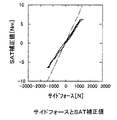
図30は、横軸を上記(27)式に従って推定された前輪サイドフォースとしたときのSAT補正値を示したものである。横軸をサイドフォースとする場合も横軸をスリップ角とした場合と同様に、操舵系の摩擦を除去することによってSATのヒステリシス特性が除去されていることが理解できる。図30には、同時に本実施の形態の空気圧低下判定手段54のSAT基準値設定手段54Bにおいて設定されたSAT基準値を一点鎖線で示している。
【0184】
この実験では、原点近傍の領域を除き常にSAT補正値はSAT基準値以下となっており、直進状態を除く広い領域で空気圧低下判定が行われることが予測できる。
【0185】
ところで、前述の第5の実施の形態の構成では、ヨー角速度や横加速度等の車両運動状態量を計測するセンサが必要ないという特徴があるが、空気圧低下に伴うスリップ角推定の誤差の影響を受けるという問題もある。すなわち、車両運動方程式のパラメータであるコーナリングスティッフネスは、サイドフォース勾配と同じものであり、サイドフォース勾配は(23)式に示すように空気圧変化に伴うタイヤの接地長変化の影響を受ける。このため、車両運動の動特性も空気圧変化の影響を受け、例えば、自然空気漏れ等の4輪同時に空気圧が低下した状態とパンク等の前輪1輪のみ低下する状態とでは、同じ操舵を行った場合のスリップ角の大きさが異なる。
【0186】
これに対し、第5の実施の形態では、パラメータを固定した車両運動モデルに基づいてスリップ角を推定しているため、4輪同時に空気圧が低下した状態と前輪1輪のみ空気圧が低下した状態とで同じ値を出力する。この演算結果は、空気圧低下判定の誤差要因になり得ると考えられる。
【0187】
これに対し、第6の実施の形態では(27)式に基づいて推定演算されるサイドフォースを用いている。このサイドフォースは(27)式から明らかなように、実際のサイドフォースを反映した車両運動の動特性から直接導出している結果、コーナリングスティッフネスの影響を受けていない。このため、4輪同時に空気圧が低下した状態や前輪1輪のみ空気圧が低下した状態との異なる状況によらず、常に正確なサイドフォースの推定が可能である。
【0188】
また、空気圧低下判定手段と54して、SAT基準値設定手段54Bを用いることなく、前輪サイドフォースとヨー角速度に施したフィルタと同じカットオフ周波数をもつローパスフィルタ処理を施したSAT補正値とから、サイドフォースの微小変化に対するSAT補正値の微小変化の比で表されるサイドフォースにた対するSAT補正値の勾配を演算し、このサイドフォースに対するSAT補正値の勾配が一定値以上になった場合に、空気圧が低下したと判定することもできる。
【0189】
なお、サイドフォースに対するSAT補正値の勾配は、前述のスリップ角に対するSAT補正値の勾配を求めるアルゴリズムのスリップ角をサイドフォースに置き換えた演算によって推定することが可能である。また、SATとサイドフォースの特性の場合、バンク走行時等路面カントによる影響は受けないため、推定パラメータのうち切片を0に固定して考えても良い。この場合、オンライン最小2乗法の推定パラメータは、勾配のみとなり演算負荷の低減効果も期待できる。以下にこのときのアルゴリズムを詳述する。
【0190】
ここでは、SATとサイドフォースに次の関係が成立していると仮定する。
【0191】
【数26】
![]()
ただし、kは、サイドフォースに対するSAT補正値の勾配である。このとき上記(28)式にオンライン最小2乗法を適用すると、以下の(29)式が得られる。
【0193】
【数27】
ただし、λfは忘却係数である。
【0195】
この手法は、図30のSAT補正値の勾配を推定し、推定された勾配と所定値(一点鎖線で表される勾配)との比較を行うものである。この手法を用いる場合、直進付近の微小な操舵状態においても勾配を推定することが可能であるため、直進に近い走行条件でも空気圧低下の判定が可能となる。また、ブラッシュモデルによって記述する場合、サイドフォースに対するSAT補正値の勾配kは(27),(28)式より、
【0196】
【数28】
となる。これは、トレッドラバーの剛性や接地幅に依存することなく、接地長のみ検出できることを意味している。したがって、サイドフォースに対するSAT補正値の勾配を導出する手法の場合、スタッドレスやサマーといったタイヤ種別やタイヤサイズに依存せず、精度良く空気圧の低下判定が可能である。
【0198】
以上説明したように本実施の形態によれば、保舵時のドライバの操舵トルク変動に影響を受けない推定が可能になると共に、レーンチェンジなど比較的速い操操舵時においても推定が可能になる。
【0199】
したがって、SAT補正手段において操舵系の摩擦を除去するため、保舵時にハンドルが動かない程度にドライバが操舵トルクを変動させても、変動分が摩擦として除去されるためにSAT補正値は一定に保たれ、正確な空気圧低下判定が行われる。
【0200】
また、タイヤ発生力の基になる前輪スリップ角を推定し、このスリップ角とSAT補正値との関係から空気圧低下判定を行うため、推定値が車両運動の動特性の影響を受けず、速い操舵の状態でも正確な判定が可能となる。
【0201】
なお、本実施の形態では、上記(23)式に従って、スリップ角に対するサイドフォース勾配を演算し、このサイドフォース勾配が所定値以上になったときに空気圧が低下したと判断するようにしてもよい。
【0202】
上記で説明したように、タイヤの空気圧が低下するとタイヤと路面との接地長が長くなるため、タイヤと路面との間の摩擦係数が大きくなったのと等価とみなすことができ、タイヤの空気圧低下と路面摩擦状態とは密接な関係にある。従って、路面摩擦状態推定について説明した実施の形態はタイヤの空気圧低下推定に用いることができ、タイヤの空気圧低下推定について説明した実施の形態は路面摩擦状態推定に用いることができる。
【0203】
【発明の効果】
以上説明したように本発明によれば、ヒステリシス特性を持つ第2の物理量からヒステリシス特性を除去し、このヒステリシス特性を除去した第2の物理量に基づいて第3の物理量を推定しているため、精度の高い物理量を推定することができる、という効果が得られる。
【0204】
また、セルフアライニングトルクに基づいてヒステリシス特性を除去した補正値を出力し、この補正値に基づいて路面摩擦状態またはタイヤの空気圧低下を推定しているので、全操舵角範囲において正確に路面摩擦状態またはタイヤの空気圧低下を推定することができる、という効果が得られる。
【0205】
そして、セルフアライニングトルクに基づいてヒステリシス特性を除去した補正値を出力し、この補正値に基づいて操舵角中立点を推定しているので、正確に操舵角中立点を推定することができる、という効果が得られる。
【図面の簡単な説明】
【図1】電動パワーステアリング装置が搭載された車両に本発明を適用した第1の実施の形態を示すブロック図である。
【図2】スリップ角基準値の上限及び下限を示す線図である。
【図3】スリップ角基準値の演算方法を説明するための線図である。
【図4】SAT−スリップ角特性の路面摩擦状態による相違を示す線図である。
【図5】低グリップ状態でのスリップ角を示す線図である。
【図6】粘性補償後のSATとスリップ角との関係を示す線図である。
【図7】粘性補償前のSATとスリップ角との関係を示す線図である。
【図8】(A)は操舵角の時間変化を示す線図であり、(B)はSATとスリップ角の時間変化を示す線図である。
【図9】高μ路走行時のスリップ角基準値及びスリップ角推定値の時間変化を示す線図である。
【図10】低μ路走行時のスリップ角基準値及びスリップ角推定値の時間変化を示す線図である。
【図11】スリップ角の絶対値とスリップ角基準値の絶対値との差と、グリップ状態との関係を示す線図である。
【図12】高μ路走行時のグリップ状態とスリップ角の時間変化を示す線図である。
【図13】低μ路走行時のグリップ状態とスリップ角の時間変化を示す線図である。
【図14】電動パワーステアリング装置が搭載された車両に本発明を適用した第2の実施の形態を示すブロック図である。
【図15】SAT補正値の上限及び下限を示す線図である。
【図16】SAT推定値からSAT補正値を演算する方法を説明するための線図である。
【図17】(A)はSAT推定値の時間変化を示す線図であり、(B)はヒステリシス特性を除去したSAT補正値の時間変化を示す線図である。
【図18】(A)は高μ路及び低μ路におけるスリップ角とSAT推定値との関係を示す線図であり、(B)は高μ路及び低μ路におけるスリップ角とSAT補正値との関係を示す線図である。
【図19】(A)は高μ路走行時のSAT基準値とSAT補正値との時間変化を示す線図であり、(B)は低μ路走行時のSAT基準値とSAT補正値との時間変化を示す線図である。
【図20】SAT基準値の絶対値とSAT補正値の絶対値との差と、グリップ状態との関係を示す線図である。
【図21】(A)は高μ路走行時のグリップ状態とスリップ角推定値とを示す線図、(B)は低μ路走行時のグリップ状態とスリップ角推定値とを示す線図である。
【図22】本発明をハンドルの中立点の位置を推定する装置に適用した第3の実施の形態を示すブロック図である。
【図23】SAT推定値からSAT補正値を演算する方法を説明するための線図である。
【図24】本発明をハンドル操舵時の粘性を推定する装置に適用した第4の実施の形態を示すブロック図である。
【図25】本発明の他の適用例を示すブロック図である。
【図26】本発明をタイヤの空気圧低下を推定する装置に適用した第5の実施の形態を示すブロック図である。
【図27】(A)は操舵角とSAT推定値との関係を示す線図であり、(B)はスリップ角とSAT推定値及びSAT補正値との関係を示す線図である。
【図28】本発明をタイヤの空気圧低下を推定する装置に適用した第6の実施の形態を示すブロック図である。
【図29】図28のサイドフォース推定手段及び空気圧低下判定手段の詳細を示すブロック図である。
【図30】サイドフォースとSAT補正値との関係を示す線図である。
【符号の説明】
10 ステアリングシャフト
12 ステアリングホイール
14 ステアリングギヤ
16 タイロッド
18 操舵角センサ
20 トルクセンサ
22 電気制御装置
24 減速機
26 電気モータ
30 車速センサ
32 アシストトルクセンサ
34 スリップ角推定手段
36 SAT推定手段
38 スリップ角基準値演算手段
40 摩擦状態推定手段
42 ヒステリシス特性除去手段
44 摩擦状態推定手段[0001]
BACKGROUND OF THE INVENTION
The present invention relates to a physical quantity estimation device, a road surface friction state estimation device, a steering angle neutral point estimation device, and a tire air pressure drop estimation device, and in particular, a physical quantity estimation device that estimates a physical quantity based on a correction value from which hysteresis characteristics are removed, A road friction state estimation device that obtains a correction value by removing hysteresis characteristics caused by the influence of viscous friction such as coulomb friction from the estimated value of self-aligning torque (SAT), and estimates the road surface friction state based on the obtained correction value Steering angle neutral point estimation device for estimating neutral point of steering angle based on correction value and steering angle from which hysteresis characteristic has been removed, and decrease in tire air pressure based on correction value and SAT reference value from which hysteresis characteristic has been removed The present invention relates to a tire pressure drop estimation device for estimating the tire pressure.
[0002]
[Prior art and problems to be solved by the invention]
Japanese Patent Application Laid-Open No. 11-287749 detects the steering angle and steering torque of a tire, calculates the characteristics of the steering torque with respect to the steering angle, and based on the calculation result, the friction coefficient μ (road surface) A technique for computing μ) is disclosed.
[0003]
In this prior art, since the road surface μ, which is a physical quantity corresponding to the grip state, is obtained as the amount of change in the steering torque with respect to the amount of change in the steering angle, it is an estimation method that is easily affected by noise. In other words, obtaining the amount of change means performing differentiation to amplify the noise, and therefore the estimated value is a value containing a lot of noise.
[0004]
Further, in this prior art, since the road surface μ is estimated only when the steering angle is increased, the friction coefficient cannot be estimated because the increase cannot be performed at the maximum steering angle at which the load applied to the tire is the largest. Originally, the estimation accuracy is improved by estimating the road surface μ when the load applied to the tire is the largest, that is, near the limit, that is, estimating the road surface μ of the limit. There is a problem in that μ cannot be estimated and the road surface μ can be estimated only before reaching the maximum steering angle.
[0005]
By the way, a hysteresis characteristic is generated between the SAT and the slip angle or the steering angle due to the twist of the tire tread, the Coulomb friction of the power steering device, or the like. For this reason, the characteristics differ between when the steering angle is increased and when it is switched back, and the estimated value varies in the conventional method that focuses on the change in the SAT with respect to the change in the slip angle or the steering angle.
[0006]
Also, if the driver decreases the steering force to such an extent that the steering wheel does not move during steering, the SAT decreases despite the fact that the slip angle or the steering angle does not change, resulting in a “grip state decreased” There is a possibility of misjudgment. That is, in the above-described prior art, estimation is performed only at the time of additional cutting to avoid such a misjudgment and to reduce the variation of the estimated value. There is a problem that cannot be estimated.
[0007]
In addition, the fact that the road surface friction state cannot be estimated at the time of switching back and steering means that the grip state changes, for example, when switching from a low μ road to a high μ road in a steering state or from a high μ road to a low μ road. In this case, the road surface friction state cannot be estimated at the time of change, and the grip state cannot be estimated until the steering angle is increased. For this reason, the estimated value of the grip state according to the prior art cannot be used as a control parameter for switching the characteristics of the power steering apparatus or ABS that requires fast adaptability according to the grip state.
[0008]
In Japanese Patent Laid-Open Nos. 11-334634 and 11-59466, a reference steering torque set based on the steering angle and the vehicle speed is compared with the steering torque, and the steering torque is larger than the reference steering torque. Describes a technique for determining that the tire air pressure has decreased when the air pressure continues for a certain period of time.
[0009]
In the above prior art, since the steering torque including the friction of the steering system is used, the change of the steering torque with respect to the air pressure is affected by this friction, so that it cannot be accurately detected, and the air pressure is highly accurate due to the influence of the friction. There is a problem that it is not possible to estimate the decrease in.
[0010]
Further, the steering angle and the steering torque are affected by the dynamic characteristics of the vehicle motion in addition to the friction of the steering system. For this reason, there is a concern that the estimation accuracy may deteriorate when fast steering is performed.
[0011]
As a countermeasure against the above problem, the prior art adds a condition that the state where the steering torque is larger than the reference steering torque continues for a certain period of time, and this condition alleviates the problem of accuracy degradation. However, there is a new problem that the estimation opportunities are reduced by this condition, and as a result, the estimation time is delayed.
[0012]
The present invention has been made in order to solve the above problems, and in order to prevent variations in estimated values, a physical quantity estimation device capable of estimating a physical quantity with high accuracy by removing hysteresis characteristics, and a steering angle are provided. A road surface friction state estimation device that can accurately estimate the road surface friction state without increasing the angle, a steering angle neutral point estimation device that can accurately estimate the neutral point of the steering angle, and a tire pressure drop estimation An object of the present invention is to provide a tire pressure drop estimation device that can be used.
[0013]
[Means for Solving the Problems]
In order to achieve the above object, the physical quantity estimation apparatus of the present invention provides: For steering wheel angle or steering wheel slip angle A first output means for outputting a steering state of a steered wheel having no hysteresis characteristic; a second output means for outputting a self-aligning torque estimated value estimated from a steering torque and an assist torque; and the self-aligning. From estimated torque , Against steering wheel angle or steering wheel slip angle Hysteresis removing means for removing a hysteresis characteristic and calculating a self-aligning torque correction value, and one of a wheel state and a road surface state during traveling of the vehicle based on the steering state of the steering wheel and the self-aligning torque correction value And an estimation means for estimating a physical quantity.
[0014]
According to the present invention, For steering wheel angle or steering wheel slip angle From estimated self-aligning torque with hysteresis characteristics For steering wheel angle or steering wheel slip angle Since the physical quantity related to one of the wheel state and the road surface condition during traveling of the vehicle is estimated based on the self-aligning torque correction value from which the hysteresis characteristic has been removed, the physical quantity with high accuracy can be estimated. As a result, a physical quantity related to one of the wheel state and road surface condition during traveling of another vehicle can be estimated from a highly accurate self-aligning torque correction value, so that the estimated physical quantity does not vary.
[0015]
In the present invention, the steering state of the steered wheel is, for example, Handle angle or The slip angle of the steering wheel can be set.
[0016]
This self-aligning torque correction value is an arithmetic expression having a gradient represented by the ratio of the change of the self-aligning torque correction value to the change of the self-aligning torque estimated value, and the self-aligning torque estimated value by Coulomb friction It is possible to calculate with a different calculation formula for each region in which the gradient of the region where the fluctuation is smaller than the gradient of the region other than the region.
[0017]
In addition, the hysteresis characteristic represents a predetermined physical relationship between a physical quantity having a hysteresis characteristic and the same physical quantity having no hysteresis characteristic as a graph or a table, and has a hysteresis characteristic based on this physical relation. It can be removed by converting the physical quantity into a physical quantity having no hysteresis characteristic. In this case, conversion is facilitated by predetermining the initial value according to the previous history.
[0018]
A physical quantity (for example, a decrease in tire air pressure or a road surface friction state) related to one of a wheel state and a road surface state when the vehicle travels is determined by the slip of the steering wheel. Horns and Based on the self-aligning torque correction value or slip of the steered wheels In the corner It can be estimated based on the self-aligning torque reference value and the self-aligning torque correction value set accordingly.
[0019]
Also, the slope of the self-aligning torque correction value expressed as the ratio of the change in the self-aligning torque correction value to the change in the slip angle. To Based on this, it is possible to estimate a physical quantity related to one of the wheel state and the road surface state during vehicle travel.
[0020]
Further, the physical quantity related to one of the wheel state and the road surface state during vehicle travel can be estimated based on the slip angle of the steered wheel and either the slip angle reference value or the self-aligning torque correction value.
[0021]
The slip angle reference value is an arithmetic expression having a gradient represented by the ratio of the change in the slip angle reference value to the change in the self-aligning torque estimated value, and is a region where the self-aligning torque estimated value varies due to Coulomb friction. The gradient may be calculated by a different calculation formula for each region in which the gradient is smaller than the gradient of the region other than the region.
[0022]
A road surface friction state estimating device of the present invention includes a steering angle sensor that detects a steering angle, a vehicle speed sensor that detects a vehicle speed, a torque sensor that detects steering torque, an assist torque sensor that detects steering assist torque, and a steering A slip angle estimating means for estimating a slip angle of a steered wheel based on an angle and a vehicle speed; a self aligning torque estimating means for outputting a self aligning torque estimated value based on a steering torque and an assist torque; Based on the relationship between the self-aligning torque estimated value and the slip angle, for the self-aligning torque estimated value, The hysteresis characteristic for the steering wheel angle or the steering wheel slip angle has been removed. It includes hysteresis removing means for calculating a slip angle reference value, and friction state estimating means for estimating a road surface friction state from the slip angle reference value and the slip angle.
[0023]
The slip angle estimating means of the road surface friction state estimating device of the present invention estimates the slip angle of the steered wheel (for example, the front wheel) using the steering angle and the vehicle speed based on the vehicle motion model. The self-aligning torque (SAT) estimating means estimates the SAT that is the road surface reaction force by adding the steering torque and the assist torque, specifically, based on the steering torque and the assist torque. The steering torque is detected by, for example, a torque sensor mounted coaxially with the steering wheel, and the assist torque is calculated from the current of the electric power steering device, for example.
[0024]
The SAT estimation accuracy can be improved by subtracting the viscous friction torque generated in proportion to the steering angular velocity from the value obtained by adding the steering torque and the assist torque. Further, the SAT may be estimated by the disturbance observer method described in Japanese Patent Application No. 2000-370704 using the steering angular velocity in addition to the steering angle. By using the disturbance observer method, it is possible to estimate the SAT in consideration of the torque generated by the inertia of the power steering apparatus.
[0025]
The hysteresis removing means is based on the relationship between the self-aligning torque estimated value and the slip angle. For steering wheel angle or steering wheel slip angle A slip angle reference value for the estimated self-aligning torque value from which the hysteresis characteristic has been removed is calculated.
[0026]
That is, the hysteresis removing means can calculate the slip angle with respect to the self-aligning torque estimated value as a correction value based on the physical relationship between the self-aligning torque having hysteresis characteristics and the slip angle. That is, a slip angle (slip angle reference value) that takes into account hysteresis characteristics caused by Coulomb friction of the power steering device or the like from the SAT estimated value estimated by the SAT estimating means is output as a correction value. Since the slip angle reference value is a slip angle of a steered wheel, for example, a front wheel, generated in a steering region where the grip state is sufficiently high and there is a margin, the hysteresis characteristic with respect to the estimated value of the self-aligning torque is removed.
[0027]
The friction state estimating means compares the slip angle of the steered wheel estimated by the slip angle estimating means with the slip angle reference value output from the hysteresis removing means, and the slip angle is reduced as the grip state, that is, the road surface friction state is lowered. The grip state, that is, the road surface friction state is estimated by utilizing the fact that the slip angle becomes larger than the reference value.
[0028]
Further, the hysteresis removing means replaces the above-described removal method with a hysteresis from the self-aligning torque estimated value based on a physical relationship between the self-aligning torque estimated value and the self-aligning torque correction value from which the hysteresis characteristic is removed. The self-aligning torque from which the characteristics are removed may be calculated as a self-aligning torque correction value. In this case, a self-aligning torque (SAT correction value) obtained by removing the hysteresis characteristic directly from the estimated value of the self-aligning torque is calculated.
[0029]
The friction state estimating means compares the SAT reference value calculated by multiplying the slip angle of the steered wheel estimated by the slip angle estimating means with a coefficient that changes according to the vehicle speed and the tire type, and the SAT correction value. The grip state, that is, the road surface friction state is estimated by utilizing the fact that the SAT correction value becomes smaller than the SAT reference value as the state, that is, the road surface friction state decreases.
[0030]
As described above, according to the present invention, the correction value from which the hysteresis characteristic is removed is output based on the self-aligning torque, and the road surface friction state is estimated based on this correction value. The road surface friction state can be estimated accurately at
[0031]
The steering angle neutral point estimation device of the present invention includes a steering angle sensor that detects a steering angle, a torque sensor that detects a steering torque, an assist torque sensor that detects steering assist torque, a steering torque, and an assist torque. A self-aligning torque estimating means for outputting a self-aligning torque estimated value based on the self-aligning torque estimated value, Remove the hysteresis characteristics for the steering wheel angle or the slip angle of the steering wheel, Based on the hysteresis removing means for calculating the self-aligning torque correction value using the value when the estimated value becomes 0 as the initial value, and the self-aligning torque correction value and the steering angle, Neutral point estimating means for estimating the steering angle when the value becomes 0 as the neutral point of the steering angle.
[0032]
The self-aligning torque (SAT) estimating means of the present invention estimates the SAT based on the steering torque and the assist torque as described above. The hysteresis removing means uses the value when the estimated value of SAT becomes 0 as the initial value, For steering wheel angle or steering wheel slip angle SAT having hysteresis characteristics For steering wheel angle or steering wheel slip angle From the physical relationship with SAT without the hysteresis characteristics For steering wheel angle or steering wheel slip angle The SAT correction value from which the hysteresis characteristic has been removed is output. Then, based on the SAT correction value and the steering angle, the neutral point estimation means estimates the steering angle when the correction value becomes 0 as the neutral point of the steering angle.
[0033]
A tire pressure drop estimation device according to the present invention includes a lateral acceleration sensor that detects lateral acceleration, a yaw angular velocity sensor that detects a yaw angular velocity, a torque sensor that detects steering torque, and an assist torque sensor that detects steering assist torque. And a side force estimating means for estimating the side force of the steered wheel based on the lateral acceleration and the yaw angular velocity, and a self-aligning torque estimation for outputting a self-aligning torque estimated value based on the steering torque and the assist torque. Means and the self-aligning torque estimate For steering wheel angle or steering wheel slip angle Hysteresis removal means for removing a hysteresis characteristic and calculating a self-aligning torque correction value, and an air pressure decrease for estimating whether the tire air pressure has decreased based on the self-aligning torque correction value and the side force And an estimation means.
[0034]
In this tire pressure drop estimation device, instead of the steering angle sensor and the vehicle speed sensor, a lateral acceleration sensor for detecting lateral acceleration and a yaw angular velocity sensor for detecting yaw angular velocity are provided, and the lateral acceleration and the yaw angular velocity are converted to each other. The side force of the steered wheel may be estimated based on the self-aligning torque correction value and the side force, and it may be estimated whether or not the tire air pressure has decreased.
[0035]
The decrease in tire air pressure is based on the self-aligning torque correction value and the self-aligning torque reference value set according to the steering wheel slip angle, and the self-aligning torque correction value and the side force of the steering wheel. On the basis of the self-aligning torque reference value set in accordance with or based on the gradient of the self-aligning torque correction value represented by the ratio of the change in the self-aligning torque correction value to the change in the slip angle, Can be estimated.
[0036]
Further, based on the gradient of the self-aligning torque correction value represented by the ratio of the change in the self-aligning torque correction value to the change in the side force, it may be estimated whether or not the tire air pressure has decreased. .
[0037]
The ratio between the SAT correction value and the SAT reference value calculated by the air pressure decrease determination means is a value that increases when the air pressure decreases, and when this value exceeds a threshold value, it is possible to determine the air pressure decrease. However, this value is also a value representing the grip state at the same time, and becomes a small value when the grip is lowered, such as when traveling at a low μ. For this reason, if the ratio between the SAT correction value and the SAT reference value exceeds the threshold value for determining the air pressure, it is determined that the air pressure has decreased, and the ratio between the SAT correction value and the SAT reference value falls below the threshold value for determining the grip decrease. In this case, it can be determined that the grip is lowered.
[0038]
Note that a decrease in the ratio between the SAT correction value and the SAT reference value due to the grip reduction occurs with steering, and the change is relatively fast, whereas the SAT correction value and the SAT reference due to the decrease in air pressure. The increase in ratio with the value is slowly changing. For this reason, when the ratio between the SAT correction value and the SAT quasi-value is identified by the online least square method, the air pressure estimation logic sets a larger forgetting factor or decimation than the grip degree estimation logic. Therefore, it is desirable to capture a slow change in the ratio between the SAT correction value and the SAT reference value by thinning out the data. In addition, when determining the decrease in air pressure, it is desirable to use data in the vicinity of a straight traveling state with a small slip angle that is not affected by a decrease in grip, so data when steering is performed with a relatively large slip angle. Can be removed by sorting.
[0039]
DETAILED DESCRIPTION OF THE INVENTION
DESCRIPTION OF THE PREFERRED EMBODIMENTS Embodiments in the case where the present invention is applied to a vehicle that is steered by front wheels will be described below in detail with reference to the drawings. First, the road surface friction state estimation apparatus according to the first embodiment will be described.
[0040]
As shown in FIG. 1, an electric power steering apparatus mounted on a vehicle is provided with a steering wheel (handle) 12 fixed to an upper end portion of a steering
[0041]
[0042]
A
[0043]
The steering torque signal output from the
[0044]
A
[0045]
Further, the vehicle is provided with a
[0046]
The
[0047]
The SAT estimation means 36 is connected to a slip angle reference value calculation means 38 that calculates a slip angle reference value from the estimated SAT.
[0048]
In the above description, the slip
[0049]
Hereinafter, the operation of each means of the present embodiment will be described. The slip angle estimating means 34 estimates the slip angle of the front wheel using the following equation of state using the dynamic characteristics of the vehicle motion based on the input steering angle signal and vehicle speed signal.
[0050]
[Expression 1]
However,
v: lateral velocity (m / s),
r: Yaw angular velocity (rad / s),
α f : Front wheel slip angle (rad),
u: vehicle speed (m / s),
c f : Front wheel cornering power (N / rad),
c r : Rear wheel cornering power (N / rad),
L f : Distance between front axle centers of gravity (m),
L r : Distance between center of gravity of rear axis (m),
M: vehicle mass (kg),
I z : Yaw inertia (kgm 2 ),
g h : Steering wheel actual gear ratio,
θ p : Handle angle (steering angle),
And the symbol ^ indicates an estimated value.
[0052]
When the above equations (1) and (2) are discretized by the sample time τ and expressed as a function of the vehicle speed, the following equations (3) and (4) are obtained.
[0053]
[Expression 2]
However, As and Bs in the expression (3) are
[0055]
[Equation 3]
It is.
[0057]
Therefore, the front wheel slip angle α f Can be calculated by the above equation (4) for each sample time τ.
[0058]
The SAT estimation means 36 is a steering torque (torque sensor measurement value) T measured by the
[0059]
[Expression 4]
Where g p Is pinion reed, g b Is the ball screw lead, k m Is an assist motor torque constant, both of which are constants.
[0061]
In addition, if the viscous friction of the power steering device is taken into consideration and the calculation is performed based on the following equation using the steering speed, the SAT estimated value T can be more accurately calculated. SAT Can be estimated.
[0062]
[Equation 5]
Here, c is a value obtained by equivalently converting the viscosity of each element such as the motor, the pinion shaft, and the rack of the power steering device into the viscosity of the pinion shaft (handle steering shaft).
[0064]
Furthermore, by using a disturbance observer, the estimated SAT value T taking into account the inertia of the power steering device SAT Can be estimated. Hereinafter, estimation using a disturbance observer will be described. The dynamic characteristics of the electric power steering apparatus are described by the following differential equation.
[0065]
[Formula 6]
However, M r Is the rack mass, J m Is the motor inertia. Here, when the right side of the equation (7) is regarded as a disturbance estimated by the disturbance observer, a disturbance observer such as the following equation can be configured.
[0067]
[Expression 7]
G represents an observer gain, and symbol ^ represents an estimated value of each state quantity. Equation (8) is obtained by discretizing the steering speed dθ shown in the following equation: p / Dt and steering angle θ p Is a recurrence formula for estimating the disturbance d.
[0069]
[Equation 8]
However, A, B, C, and D are system matrices obtained by discretizing Equation (8). The estimated value of SAT can be calculated by the following equation (13).
[0071]
[Equation 9]
The slip angle reference value calculation means 38 calculates a slip angle reference value (slip angle reference value) from the SAT estimation value estimated by the SAT estimation means 36 in consideration of hysteresis characteristics caused by Coulomb friction or the like of the power steering device. The calculation of the slip angle reference value is performed by the logic described below. This logic is an arithmetic expression having a gradient (gradient) represented by the ratio of the change in the slip angle reference value to the change in the SAT estimated value, and the gradient K in the region where the SAT estimated value varies due to Coulomb friction. 1 Is the gradient K of the region other than this region 2 The calculation is performed using different calculation formulas for each of the smaller areas.
[0073]
FIG. 2 shows the upper limit and the lower limit of the slip angle reference value of the slip angle-SAT model, and the slope of the straight line representing each boundary is K 2 It is. The slope K of this line 2 Represents the relationship between the SAT generated when steering in a high grip state and the front wheel slip angle. The width between the upper limit and the lower limit represents the size of the hysteresis characteristic, and the interval on the horizontal axis of the two straight lines is the friction torque T generated by Coulomb friction. fric Represents.
[0074]
This slope K 2 The friction state can be estimated more precisely by changing the speed according to the traveling vehicle speed. Furthermore, this slope K 2 Is desired to be changed depending on the type of tire mounted, and may be changed according to the tire type when the type such as a studless tire or a summer tire is determined.
[0075]
FIG. 3 shows a method for calculating the slip angle reference value. In the straight traveling state, SAT is 0, and 0 is output as the slip angle reference value at this time. Next, when steering is performed and SAT is generated, the slip angle reference value is a slope K with respect to SAT. 1 Is calculated based on the straight line. In the computer, the calculation is performed based on the following formula using discretized logic.
[0076]
[Expression 10]
![]()
Where α 0 Is a slip angle reference value, and k represents time. This slope K 1 Is K 2 It is set to be smaller than the above, and represents that the fluctuation of the slip angle that occurs even if the SAT fluctuates due to Coulomb friction or the like is reduced. Further, when the steering is performed and the calculated value of the slip angle reference value according to the equation (14) reaches point A in FIG. 3 and SAT further increases, the slip angle reference value becomes the lower limit of the slip angle-SAT model. It increases according to the following formula along the straight line.
[0078]
[Expression 11]
![]()
Further, when the steering is further performed and the increase to the point B is finished and the increase of the SAT is started and the SAT starts to decrease, the slip angle reference value becomes the slope K. 1 In accordance with the equation (14). In this region, the variation of the slip angle reference value is set to be small with respect to the variation of SAT. This expresses that even if the driver's steering force is slightly changed in the steering state during turning, the steering angle and the front wheel slip angle are not affected by the influence of Coulomb friction or the like of the power steering device.
[0080]
When the SAT increases again at the point C reached by the decrease of the SAT from the point B, the slip angle reference value increases toward the point B according to the equation (14). Further, when the SAT further decreases from the point C due to the switchback and reaches the upper limit of the slip angle-SAT model, the slip angle reference value decreases according to the equation (15) along the straight line representing the upper limit. In this way, two types of gradients K that differ depending on each region 1 , K 2 The hysteresis characteristic shown in FIG. 3 is realized by an arithmetic expression having the following equation, and the front wheel slip angle is estimated from the SAT time-series signal assuming a high grip state, that is, a state where there is a sufficient margin in a grip state such as driving on a high μ road surface. it can. Therefore, the slip angle reference value is obtained by calculating the slip angle of the front wheels generated in the steering region where the grip state is sufficiently high and there is a margin from the estimated SAT value. Further, since the slip angle reference value is the slip angle of the front wheel that occurs in a steering region where the grip state is sufficiently high and there is a margin, the hysteresis characteristic with respect to the estimated value of the self-aligning torque is removed.
[0081]
The friction state estimation means 40 compares the estimated value of the front wheel slip angle estimated by the slip angle estimation means 34 with the slip angle reference value calculated by the slip angle reference value calculation means. The grip state, that is, the road surface friction state is calculated by utilizing the fact that the slip angle becomes larger than the angle reference value.
[0082]
The grip state (road surface friction state) can be calculated from the map shown in FIG. 11 using the difference between the absolute value of the front wheel slip angle and the absolute value of the slip angle reference value. The grip state calculated here is standardized in the range of [0, 1], and the larger the grip state, the higher the grip. As the difference between the absolute value of the front wheel slip angle and the absolute value of the slip angle reference value increases from the map shown in FIG. 11, the grip state, that is, the road surface friction state is estimated to be smaller, and the absolute value of the front wheel slip angle and the slip angle reference value are estimated. As the difference from the absolute value of the value becomes smaller, the grip state, that is, the road surface friction state is estimated to be larger. Instead of this deviation, the road surface friction state may be estimated using a ratio between the absolute value of the front wheel slip angle and the absolute value of the slip angle reference value.
[0083]
Here, when steering is performed in a state where the grip state is lowered, such as when driving on a low μ road, a slope (slip angle− As shown in FIG. 4, the slope of the tangent line at the point where the slip angle of the SAT curve is a predetermined value is smaller than that in the high grip state. Therefore, contrary to FIG. 3, when SAT is described on the horizontal axis and the front wheel slip angle is described on the vertical axis, as shown in FIG. 5, the grip is lower than the slip angle reference value assuming a high grip state. The front wheel slip angle in the state increases, and the inclination of the SAT with respect to the front wheel slip angle increases as the grip state decreases. Since the slip angle reference value is obtained by calculating from the SAT the slip angle of the front wheel that occurs in the steering region where the grip state is sufficiently high and there is a margin, the front wheel slip angle and the slip angle reference value are calculated using this characteristic. By comparing the two, it is possible to determine the decrease in the grip state. As described above, the deviation between the front wheel slip angle and the slip angle reference value may be used as it is as an index of grip reduction, but the vehicle speed, tire type, braking / driving, etc. with respect to the slip angle reference value It is also possible to perform weighting according to the state and to standardize it.
[0084]
In this embodiment, a model that estimates the slip angle in a high grip state from the SAT time-series signal is used, and the reference slip angle that is the output of this model is compared with the actual front wheel slip angle (estimated from the steering angle). By doing so, the grip state is determined. In this model, hysteresis characteristics are taken into consideration. For example, even if the driver reduces the steering force to such an extent that the steering wheel does not move during steering, the slip angle reference value that is the model output does not drop significantly. It has become. For this reason, the grip state can be estimated by comparing the slip angle reference value and the front wheel slip angle estimated value even in the steering holding state where the steering force of the driver fluctuates.
[0085]
In the first embodiment, the road surface friction state is estimated using the physical relationship between the SAT and the slip angle as in the prior art. Conversely, the SAT reference value is determined from the slip angle by the slip angle−. It is also conceivable to calculate the road surface friction state including the grip state by calculating with the SAT model and comparing the SAT reference value and the actual SAT (SAT estimated value).
[0086]
However, as described above, the actual SAT is greatly affected by the steering force fluctuation of the driver in the steered state. For this reason, in the configuration in which the SAT having a large error factor is compared with the model output, the estimation error is large, and estimation at the time of steering is difficult as in the related art.
[0087]
On the other hand, in the first embodiment, since the slip angle is compared with the reference value of the slip angle by paying attention to the slip angle with small fluctuation at the time of steering, it is accurate even at the time of steering and switching back. It is possible to estimate the road surface friction state including the grip state.
[0088]
In addition, it can be estimated at the time of switching back and steering, for example, when the grip state changes due to switching from a low μ road to a high μ road in a steering state or from a high μ road to a low μ road. This means that the estimation can be performed at the time of change without causing an estimation delay. For this reason, it is also possible to use it as a control parameter for switching the characteristics of a power steering apparatus or ABS that requires quick adaptability, which was impossible with the prior art, depending on the grip state.
[0089]
Next, an experimental result of estimation of the road surface friction state according to the first embodiment will be described. As described above, the slip angle estimating means 34 uses the dynamic characteristics of the vehicle motion and estimates the slip angle of the front wheels based on the above equations (3) and (4). The SAT estimation means 36 adds the steering torque measured by the
[0090]
FIG. 6 shows the relationship between the front wheel slip angle calculated by the equations (3) and (4) and the estimated SAT value calculated by the equation (6) when steering is performed on a high μ road at 30 km / h. It shows the relationship. In FIG. 6, a straight line indicating the upper and lower limits (see FIG. 2) of the slip angle reference value corresponding to the relationship between the SAT generated when steering in the high grip state and the front wheel slip angle is simultaneously indicated by broken lines.
[0091]
FIG. 7 shows the relationship between the steering angle and the SAT calculated based on the equation (5) that does not consider the viscosity, using the same experimental results. By using the slip angle, which is the basic state quantity of the tire-generated force, instead of the steering angle and calculating the SAT in consideration of the viscous friction generated by the power steering device, it is possible to reproduce the SAT on a broken line (a straight line indicating the upper and lower limits). ) This characteristic is the basis for estimating the road surface friction state including the grip state, and it can be expected that the estimation accuracy is improved as compared with FIG.
[0092]
8A and 8B show the time response of this experimental result (SAT is a value after viscosity compensation). In this experiment, step steering that repeats steering and holding is performed as shown in FIG. 8A, and the estimated front wheel slip angle at this time has a stepped waveform according to the steering angle. Yes. On the other hand, SAT decreases during steering as shown in FIG. 8 (B), and reproducibility is not seen in the waveform at the time of decrease. This indicates that the steering force of the driver during steering is fluctuating, and it is difficult to accurately estimate the grip state due to the fluctuation in the method of comparing the SAT with the model output. Predictable.
[0093]
On the other hand, the slip angle waveform during steering is stable, and in this embodiment, which compares the slip angle with the model output (slip angle reference value), the grip state can be accurately estimated even during steering. Can be understood.
[0094]
In the slip angle reference value calculation means 38, a slip angle reference value is calculated from the SAT estimation value estimated by the SAT estimation means 36 in consideration of hysteresis characteristics caused by Coulomb friction of the power steering device. First, in a straight traveling state where the steering angle is 0 and the SAT is 0, the initial value of the slip angle reference value is set to 0. Next, when steering is started and SAT is output, the slip angle reference value is calculated according to the recurrence formula of (14) and (15). Here, the inclination K representing the relationship between the SAT generated when steering in a high grip state and the front wheel slip angle. 2 Is set to change according to the vehicle speed. FIG. 9 shows the result of calculating the slip angle reference value from the SAT of FIG. 8B by the above algorithm and the estimated front wheel slip angle. Although the SAT waveform, which is the model input, has a decrease or vibration characteristic during steering, the slip angle reference value, which is the output, becomes a substantially constant value due to an algorithm that takes hysteresis characteristics into account. ing. It can also be seen that on the high μ road where this experiment was conducted, the slip angle reference value is in good agreement with the estimated slip angle.
[0095]
FIG. 10 shows the results of an experiment similar to FIG. 9 performed on a low μ road where the grip state decreases. In this experiment, the steering angle is almost the same as in FIG. 9, and the slip angle estimated value is the same as that in FIG. 9, but the slip angle reference value calculated from the SAT is obtained. It can be seen that there is a deviation between the estimated value of SAT and the reference value of SAT. This is because the actual front wheel slip angle becomes larger than the slip angle reference value assuming a high grip state due to a decrease in the grip state.
[0096]
The friction state estimation means 40 compares the front wheel slip angle estimated by the slip angle estimation means 34 with the slip angle reference value calculated by the slip angle reference value calculation means 38, and calculates the grip state. The grip state is calculated from the map shown in FIG. 11 using the difference between the absolute value of the front wheel slip angle and the absolute value of the slip angle reference value. The grip state calculated here is standardized in the range of [0, 1], and the larger the grip state, the higher the grip. As the difference between the absolute value of the front wheel slip angle and the absolute value of the slip angle reference value increases from the map shown in FIG. 11, the grip state, that is, the road surface friction state is estimated to be smaller, and the absolute value of the front wheel slip angle and the slip angle reference value are estimated. As the difference from the absolute value of the value becomes smaller, the grip state, that is, the road surface friction state is estimated to be larger.
[0097]
FIG. 12 shows the grip state and slip angle estimated value when traveling on a high μ road. When traveling on a high μ road, it can be estimated that such a slip angle is always in a high grip state regardless of the presence or absence of the slip angle. FIG. 13 shows the same grip state and slip angle estimated value as in FIG. 12 when traveling on a low μ road. It can be understood that the grip state is lowered when traveling on a low μ road. Further, it can be understood that the grip state becomes 1 when the slip angle becomes close to 0 during steering, and the phenomenon that the grip recovers can be accurately estimated in a region close to straight ahead.
[0098]
Next, the friction torque T causing the hysteresis characteristic occurring in the estimated SAT value fric The estimation of the will be described. Here, the difference between the estimated SAT value when the absolute value becomes the maximum during the steering wheel turning and the estimated SAT value at the steering wheel turning-back time is calculated, and this difference is calculated as the friction torque T generated by the internal coulomb friction of the steering system. fric Estimate as
[0099]
Estimated SAT value T when steering the steering wheel to the left SAT Is positive and the estimated SAT value T when the steering wheel is steered to the right SAT Is negative, and it is detected that the sign of the steering angular velocity signal supplied from the steering angular velocity sensor is inverted, the SAT estimated value T after this timing is detected. SAT Is calculated as follows.
[0100]
When the steering angular velocity signal is reversed from negative to positive and the steering wheel is steered leftward (positive direction), a positive SAT estimated value T SAT SAT estimated value T SAT Maximum value T max Is calculated according to the following equation.
[0101]
[Expression 12]
Next, when it is detected that the steering angular velocity is reversed from positive to negative due to the steering switchback, the estimated SAT value T at this time is detected. SAT And the maximum value T obtained as described above. max And the friction torque T according to the following formula: fric Is calculated.
[0103]
[Formula 13]
On the other hand, if the steering angular velocity is reversed from positive to negative and the steering wheel is steered to the right, the negative SAT estimated value T SAT Therefore, the SAT estimated value T SAT Minimum value T min Is calculated.
[0105]
[Expression 14]
Next, when it is detected that the steering angular velocity is reversed from negative to positive due to the steering switchback, the estimated SAT value T at this time is detected. SAT And the minimum value T obtained as described above. min And the friction torque T according to the following formula: fric Is calculated.
[0107]
[Expression 15]
![]()
As a result, with respect to the hysteresis characteristic that occurs every time the steering wheel is turned back, the friction torque T fric Therefore, it is possible to always estimate an accurate magnitude of the hysteresis characteristic.
[0109]
In particular, when traveling on a rough road, the road surface disturbance acts as a dither effect on the Coulomb friction inside the steering system, and the Coulomb friction term is reduced to change the Coulomb friction. Therefore, as described above, the friction torque T fric , The latest hysteresis characteristics can be compensated successively even when the magnitude of Coulomb friction changes.
[0110]
In the first embodiment, a model for obtaining the slip angle from the SAT is used, the hysteresis characteristic is removed by obtaining the slip angle reference value that is the model output when the SAT having the hysteresis characteristic is input, and the slip angle reference is obtained. An example in which the grip state is estimated by comparing the value with the estimated value of the slip angle has been described. In the second embodiment described below, the hysteresis characteristic is directly removed from the SAT having the hysteresis characteristic, and the grip state is estimated as the road surface friction state from the SAT correction value from which the hysteresis characteristic is removed and the slip angle. .
[0111]
This embodiment will be described with reference to FIG. In the present embodiment, instead of the slip angle reference calculation means shown in FIG. 1 when the microcomputer is considered as a functional block, a hysteresis characteristic removal means 42 for removing the hysteresis characteristic from the SAT is provided, and the friction state estimation means 44 The road friction state including the grip state is estimated based on the SAT correction value from which the hysteresis characteristic has been removed and the estimated slip angle estimated by the slip angle estimating means 34.
[0112]
Hereinafter, the operation of each means will be described. The hysteresis
[0113]
The friction state estimation means 44 calculates and outputs the grip state as a road surface friction state from the slip angle and the SAT correction value from which the hysteresis characteristic is removed as follows.
[0114]
The calculation of the hysteresis characteristic removal by the hysteresis characteristic removal means 42 is performed by the following logic. This logic is an arithmetic expression having a slope expressed by the ratio of the change in the SAT correction value to the change in the SAT estimate value, and the slope K of the region where the SAT estimate value fluctuates due to Coulomb friction. 1 Is calculated by a different calculation formula for each region where the slope is smaller than the slope (= 1) of the region other than this region.
[0115]
FIG. 15 is a coordinate plane showing the relationship between a SAT estimated value having hysteresis characteristics and a SAT estimated value (SAT correction value) from which hysteresis characteristics have been removed. The widths of two straight lines on the coordinate plane indicate the hysteresis characteristics. It represents the size. Since the SAT estimated value having the hysteresis characteristic and the SAT estimated value from which the hysteresis characteristic is removed are only different in size by the hysteresis characteristic, the slope of each straight line is 1.
[0116]
FIG. 16 shows a hysteresis characteristic removal calculation method. In the straight running state where both the SAT estimated value and the slip angle are 0, no hysteresis characteristic occurs, and 0 is output as the SAT correction value at this time. Next, when steering is performed and SAT occurs, the SAT correction value is K 1 It is calculated with the slope of. In the computer, calculation is performed according to the following equation (16) by the discretized logic.
[0117]
[Expression 16]
![]()
T SAT0 Is a SAT correction value from which hysteresis characteristics have been removed. This slope K 1 Is set to be smaller than 1, so that even if the SAT estimated value fluctuates due to Coulomb friction or the like, the variation in the SAT correction value is small.
[0119]
In the above equation (16), the current value of the self-aligning torque estimated value, the previous value of the self-aligning torque estimated value, and the current value of the self-aligning torque estimated value from the previous value of the self-aligning torque correction value are the Coulomb friction. If it is within the hysteresis range, if it is within the hysteresis range, the correction value calculated by the difference between the current value of the self-aligning torque correction value and the previous value of the self-aligning torque correction value When the magnitude of the change is smaller than the magnitude of the estimated value change calculated by the difference between the current value of the self-aligning torque estimated value and the previous value of the self-aligning torque estimated value, and is outside the hysteresis region, Indicates that the current value of the self-aligning torque correction value is calculated so that the correction value change matches the estimated value change. By that.
[0120]
Further, when steering is performed and the calculated value of the SAT correction value according to the equation (16) reaches point A in FIG. 16 and the estimated SAT value further increases, the SAT correction value becomes a straight line indicating the lower limit of the model. Along with the following formula:
[0121]
[Expression 17]
![]()
Further, when the steering is further performed and the point B is reached, the increase of the angle is finished and the estimated SAT value starts to decrease. 1 Thus, the SAT correction value decreases according to the equation (16). In this area, the variation of the SAT correction value is set to be smaller than the variation of the SAT estimated value. This is so that even if the driver's steering force is slightly changed in the state of steering while turning, the SAT correction value is not affected by the influence of Coulomb friction or the like of the power steering device. When the estimated SAT value increases again at the point C reached by the decrease of the SAT from the point B, the SAT correction value is calculated to increase toward the point B according to the equation (16). Further, when the estimated SAT value further decreases from the point C due to switchback and reaches the upper limit of the model, the SAT correction value is calculated so as to decrease according to the equation (17) along the straight line indicating the upper limit. The SAT correction value with respect to the estimated SAT value is uniquely determined by setting the two kinds of inclinations, and the hysteresis characteristic shown in FIG. 16 is removed.
[0123]
FIG. 17A shows a SAT estimated value when traveling on a high μ road surface, and FIG. 17B shows a SAT correction value obtained by removing hysteresis characteristics from the SAT estimated value based on equations (16) and (17). It is a thing. It can be seen from the comparison between FIGS. 17A and 17B that the fluctuation at the time of steering, which is considered to be the influence of Coulomb friction or the like, is substantially compensated by the effect of removing hysteresis.
[0124]
FIG. 18A shows the relationship between the slip angle and the estimated SAT value when traveling on a high μ road and a low μ road, and FIG. 18B shows the relationship between the slip angle and the SAT correction value. It is. It can be understood from FIG. 18B that the relationship between the slip angle and the SAT correction value is substantially linear, and the hysteresis characteristic is removed.
[0125]
The road surface friction
[0126]
That is, the road surface friction state estimation means 44 compares the SAT reference value derived by multiplying the slip angle by a coefficient that changes according to the vehicle speed and tire type, and the SAT correction value, and compares the SAT reference value and the SAT correction value. The grip state is output according to the difference. The coefficient for deriving the SAT reference value is set assuming a high grip state, and the SAT correction value is smaller than the SAT reference value in a low grip state such as when driving on a low μ road. The road surface friction state estimating means 44 uses this property to calculate and output the grip state, that is, the road surface friction state, as the deviation between the absolute value of the SAT reference value and the absolute value of the SAT correction value increases. .
[0127]
19A and 19B compare the SAT correction value (solid line) and the SAT reference value (broken line) derived by multiplying the front wheel slip angle by a coefficient that changes according to the vehicle speed. As shown in FIG. 19A, the SAT reference value calculated from the slip angle on the assumption of a high grip state substantially coincides with the SAT correction value when traveling on a high μ road, while the grip state is low. When traveling on the μ road, it can be understood that there is a deviation from the SAT correction value as shown in FIG.
[0128]
Therefore, the road surface friction state estimation means 44 calculates the road surface friction state including the grip state from the map shown in FIG. 20 using the difference between the absolute values of the SAT correction value and the SAT reference value. The road surface friction state including the grip state calculated here is standardized in a range of [0, 1], and the larger the state, the higher the grip state, that is, the road surface friction state. As the difference between the absolute value of the SAT reference value and the absolute value of the SAT correction value increases from the map shown in FIG. 20, the grip state, that is, the road surface friction state is estimated to be small, and the absolute value of the SAT reference value and the SAT correction value As the difference from the absolute value becomes smaller, the grip state, that is, the road surface friction state is estimated to be larger.
[0129]
FIGS. 21A and 21B show the grip state and slip angle estimated value when traveling on a high μ road, and the grip state and slip angle estimated value when traveling on a low μ road, respectively. As shown in FIG. 21A, it can be estimated that when the vehicle travels on a high μ road, the grip angle is always high regardless of the presence or absence of the slip angle. Further, as shown in FIG. 21B, it can be understood that the grip state is lowered when traveling on a low μ road. Further, it can be understood that the grip state becomes 1 when the slip angle becomes close to 0 during steering, and the phenomenon that the grip state is recovered can be accurately estimated in a region close to straight ahead.
[0130]
In the first embodiment, an example in which the road surface friction state including the grip state is estimated by comparison with the slip angle model and in the second embodiment by comparison with the SAT model has been described. The present invention is not limited to the configuration of the comparison with the model as described above. The grip state is described as a function of the SAT and the slip angle after removing the hysteresis, or the two-dimensional map of the SAT and the slip angle after removing the hysteresis. The road surface friction state including the grip state may be estimated.
[0131]
Further, in the above description, an example in which the present invention is applied to a vehicle equipped with an electric power steering apparatus has been described. However, if the hydraulic pressure of the power steering apparatus corresponding to the steering torque and the assist torque can be measured, the present invention is applied to the hydraulic power steering apparatus. It can also be applied to vehicles.
[0132]
Next, a third embodiment in which the present invention is applied to a steering angle neutral point estimating device will be described. In the present embodiment, the position of the neutral point, which is the steering angle of the steering wheel at which the vehicle goes straight, is estimated using the hysteresis characteristic removing means of the second embodiment.
[0133]
Hereinafter, the present embodiment will be described with reference to FIG. In the present embodiment, the slip angle calculating means 34 of FIG. 14 is omitted, and a neutral point estimating means 46 is provided in place of the friction state estimating means 44, and the SAT estimation having no steering angle and hysteresis characteristics by the neutral point estimating means 46. The position of the neutral point is estimated based on the SAT correction value that is a value. In FIG. 22, parts corresponding to those in FIG. 14 are denoted by the same reference numerals, and detailed description thereof is omitted.
[0134]
Hereinafter, the operation of each means will be described. The hysteresis
[0135]
Further, when the SAT estimated value having the hysteresis characteristic is changed from a positive value to 0 and the steering angular velocity shows a negative value equal to or less than a certain value, a straight line having an inclination of 1 passing through the point B shown in FIG. With the point as an initial value, the SAT correction value from which the hysteresis characteristic is removed is calculated by the same algorithm as described in FIG. 16 of the second embodiment.
[0136]
The neutral point estimation means 46 outputs the steering angle when the SAT correction value from which the hysteresis characteristic is removed becomes 0 as a neutral point.
[0137]
Since there is a hysteresis characteristic between the steering angle and SAT or steering torque (having a hysteresis characteristic), the conventional neutral point is generally estimated statistically from the frequency of the steering angle. It was. However, in the conventional statistical method, since a large amount of data is used, it takes a long time to complete the estimation, or an estimation error occurs due to a deviation in the steering angle when traveling on a circular course. There's a problem. In contrast, in the present embodiment, since the neutral point is estimated from the relationship between the SAT estimated value after the removal of the hysteresis characteristic and the steering angle, the neutral point can be accurately and easily estimated. It is possible to estimate the neutral point in a short time without performing a typical process and without being affected by the deviation of the steering angle.
[0138]
Next, a fourth embodiment of the present invention will be described. In this embodiment, the viscosity at the time of steering the steering wheel is estimated using the hysteresis characteristic removing means of the second embodiment. In the present embodiment, as shown in FIG. 24, instead of the friction state estimation means 44 of FIG. 14, an online identification means 48 is used, and a signal indicating the steering angular velocity is further input to the online identification means 48 and the steering wheel is steered. The viscosity is estimated. 24, parts corresponding to those in FIG. 14 are denoted by the same reference numerals, and detailed description thereof is omitted.
[0139]
The on-line identification means 48 uses an on-line identification method based on the estimated SAT value after removal of the hysteresis characteristics from which the hysteresis characteristics have been removed by the algorithm described above, the slip angle calculated by the slip angle calculation means 34, and the steering angular velocity. Apply to estimate handle viscosity.
[0140]
In this embodiment, the handle viscosity is estimated using the estimated SAT value (SAT correction value) after removing the hysteresis characteristic, so the hysteresis characteristic caused by Coulomb friction or the like is removed, and the handle viscosity estimation accuracy is improved. can do.
[0141]
The hysteresis characteristic removing means described above is not limited to the case of removing the hysteresis characteristic generated by the Coulomb friction of the handle, and can be applied to many systems including Coulomb friction. For example, the present invention can be applied to the case where the inertia of the hand load of the robot being worked is estimated online. FIG. 25 shows a configuration in which the inertia of the hand load is estimated online, and the hysteresis
[0142]
Next, a fifth embodiment for determining a decrease in air pressure will be described with reference to FIG. In the present embodiment, as described with reference to FIG. 14, the SAT estimation means 36 for calculating the SAT estimated value by adding the steering torque and the assist torque, and the hysteresis characteristic caused by the friction of the steering system is removed from the SAT estimated value. SAT correction means 42 for estimating the SAT generated between the road surface and the tire as a SAT correction value, and a slip angle estimation means 34 for estimating the slip angle of the front wheels based on the steering angle and the vehicle speed are provided. In the present embodiment, an air pressure
[0143]
Next, the estimation principle of the air pressure decrease by the air pressure decrease determination means 50 will be described. According to the brush model that theoretically describes the tire generation force characteristics, the side force F fy The self-aligning torque (SAT) Ts is expressed by the following equation.
[0144]
[Expression 18]
However,
[0146]
[Equation 19]
It is.
[0148]
here,
Fz: contact load,
l: tire ground contact length,
Ky: lateral stiffness of the tread rubber per unit width and unit length,
b: width of ground plane,
λ: side slip,
It is.
[0149]
Between this side slip λ and the front wheel slip angle,
[0150]
[Expression 20]
![]()
In general, in the region where ξ> 0, the slip angle α f Is small, and can be regarded as the following equation (22).
[0152]
[Expression 21]
![]()
From the above relationship, the ratio F of the minute change of the side force to the minute change of the slip angle near the
[0154]
[Expression 22]
Here, when the air pressure decreases, the contact length of the tire with respect to the road surface increases, so the side force gradient or the SAT correction value gradient is calculated to determine whether the side force gradient or the SAT correction value gradient has increased. By determining, it is possible to determine a decrease in tire air pressure. The air pressure decrease determination device according to the present embodiment pays attention to this feature, and detects an increase in the contact length due to the air pressure decrease as an increase in the side force gradient or the increase in the gradient of the SAT correction value.
[0156]
From the above equations (23) and (24), the side force gradient is proportional to the square of the tire contact length, whereas the SAT gradient is proportional to the cube of the tire contact length. Since the change in the contact length appears more remarkably, a decrease in air pressure can be detected with higher accuracy.
[0157]
Hereinafter, the operation of the present embodiment will be described. In this embodiment, a decrease in air pressure is determined based on the SAT gradient. The SAT estimation means 36 calculates the SAT estimated value by adding the steering torque and the assist torque, as described in FIG. Since the SAT estimated value estimated here is a value including the internal friction of the steering system, the SAT correction means 42 removes the hysteresis characteristic caused by the friction of the steering system from the SAT estimated value, and between the road surface and the tire. The actual SAT generated is estimated as the SAT correction value. Further, as described with reference to FIG. 14, the slip angle estimating means 34 estimates the slip angle of the front wheels based on the steering angle and the vehicle speed.
[0158]
Based on the estimation principle described above, the air pressure
[0159]
The gradient of the SAT correction value can be estimated and calculated using the above-described online identification method (online least square method). This online least square method estimates the gradient of the SAT correction value in FIG. 27B described below, and compares the estimated gradient with a constant value (the gradient of the one-dot chain line representing the reference gradient). is there.
[0160]
When this online least square method is used, the gradient can be estimated even in a minute steering state in the vicinity of straight ahead, so that it is possible to determine a decrease in air pressure even under a traveling condition close to straight ahead. Further, since only the gradient of the SAT correction value is focused on, it is possible to accurately determine the air pressure drop without being affected by the road surface cant even in a situation where the intercept of the SAT characteristic due to the road surface cant is shifted, such as during banking. can get.
[0161]
In the present embodiment, the example in which the decrease in the air pressure is determined using the gradient of the SAT correction value has been described. However, the present embodiment is not limited to this, and the second embodiment described above. Using the SAT reference value set according to the front wheel slip angle used in the above, the SAT reference value is compared with the SAT correction value, and when the SAT correction value becomes larger than the SAT reference value, the tire air pressure decreases. You may make it determine with having carried out. In other words, the air pressure
[0162]
FIG. 27A shows the relationship between the steering angle and the estimated SAT value when the step steering is repeated while traveling at a constant vehicle speed (30 km / h) with the air pressure being normal, that is, the steering angle and the driver steer. The relationship between the steering torque and the value obtained by adding the assist torque of the power steering is shown.
[0163]
In the prior art described in Japanese Patent Application Laid-Open Nos. 11-59466 and 11-334634, a reference torque indicated by a one-point difference line is set, and the air pressure decreases when the estimated SAT value exceeds the reference torque. Judgment. However, as shown in FIG. 27 (A), there is a hysteresis characteristic between the steering angle and the estimated SAT value. Yes.
[0164]
In the prior art, the prevention of malfunction in such a transient state is attempted by limiting the air pressure reduction judgment at the time of steering, etc., but this countermeasure limits the driving conditions that can be estimated, and problems such as judgment delay Will occur.
[0165]
On the other hand, in this embodiment, when the SAT estimated value and the SAT reference value are used, as shown in FIG. 27B, the horizontal axis is a slip angle instead of the steering angle in FIG. . The slip angle is a physical quantity that is a basis for generating a lateral force of the tire, and there is no dynamic characteristic such as a time delay between the slip angle and the SAT. On the other hand, between the steering angle and the SAT, there is a dynamic characteristic that accompanies the vehicle motion between the steering angle and the slip angle.
[0166]
In the present embodiment, since the horizontal axis is a slip angle that is not affected by the dynamic characteristics of the vehicle motion, it is possible to determine a decrease in air pressure even during a transition.
[0167]
FIG. 27B shows a change between the SAT estimated value (broken line) and the SAT correction value (solid line) from which the friction of the steering system is removed when the horizontal axis is the slip angle as described above. It can be understood that by setting the abscissa as the slip angle, the swelling of the characteristic due to the influence of the dynamic characteristic of the vehicle motion is removed, and a linear characteristic is obtained.
[0168]
Further, it can be understood that the hysteresis characteristic is also eliminated by removing the friction of the steering system in the SAT correction means 42. In FIG. 27 (B), the SAT reference value set in the air pressure drop determination means 50 of the present embodiment is simultaneously indicated by a one-dot chain line. In this experiment, it can be understood that the SAT correction value is always less than or equal to the SAT reference value except for the region near the origin, and that the determination of the decrease in air pressure is performed accurately in a wide region excluding the straight traveling state.
[0169]
Next, a sixth embodiment of the present invention will be described with reference to FIG. In this embodiment, instead of the slip angle estimation means 52 of the embodiment of FIG. 5, a
[0170]
As described above, the
[0171]
The side force estimating means 52 estimates the front wheel side force based on the lateral acceleration detected by the
[0172]
Here, front wheel side force (lateral force) F f Can be obtained from the equation of motion of the vehicle body expressed by the following equation.
[0173]
[Expression 23]
However, front wheel side force F f Is a combination of equations (25) and (26), and rear wheel side force F r Can be expressed as the following equation (27).
[0175]
[Expression 24]
However,
[0177]
[Expression 25]
It is.
[0179]
M, v, r, u, I z , L f , L r Is the same physical quantity as explained in the above formulas (1) and (2), and F f Is the front wheel side force, F r Is the rear wheel side force.
[0180]
Accordingly, as shown in FIG. 29, the side force estimating means 52 calculates a value approximated to a yaw angular velocity differential value dr / dt obtained by performing an approximate calculation by applying a high-pass or band-pass filter process to the yaw angular velocity based on the equation (27). A filter 52B for outputting, a low-
[0181]
The air pressure
[0182]
In the
[0183]
FIG. 30 shows the SAT correction value when the horizontal axis is the front wheel side force estimated according to the above equation (27). It can be understood that the hysteresis characteristic of the SAT is removed by removing the friction of the steering system when the horizontal axis is the side force, similarly to the case where the horizontal axis is the slip angle. In FIG. 30, the SAT reference value set in the SAT reference
[0184]
In this experiment, the SAT correction value is always less than or equal to the SAT reference value except in the region near the origin, and it can be predicted that the air pressure decrease determination is performed in a wide region excluding the straight traveling state.
[0185]
By the way, the configuration of the fifth embodiment described above has a feature that a sensor for measuring a vehicle motion state quantity such as a yaw angular velocity or a lateral acceleration is not necessary. However, the influence of an error in slip angle estimation due to a decrease in air pressure is affected. There is also a problem of receiving. That is, the cornering stiffness that is a parameter of the vehicle equation of motion is the same as the side force gradient, and the side force gradient is affected by the change in the contact length of the tire accompanying the change in air pressure as shown in the equation (23). For this reason, the dynamic characteristics of the vehicle motion are also affected by the change in air pressure. For example, the same steering is performed in a state where the air pressure is reduced simultaneously for four wheels such as natural air leakage and a state where only one front wheel such as puncture is reduced. The magnitude of the slip angle is different.
[0186]
In contrast, in the fifth embodiment, since the slip angle is estimated based on a vehicle motion model with fixed parameters, the state in which the air pressure is reduced at the same time for four wheels and the state in which the air pressure is reduced only for one front wheel are Will output the same value. It is considered that this calculation result can be an error factor in the air pressure decrease determination.
[0187]
On the other hand, in the sixth embodiment, a side force that is estimated and calculated based on equation (27) is used. As is apparent from the equation (27), this side force is directly derived from the dynamic characteristics of the vehicle motion reflecting the actual side force, so that it is not affected by the cornering stiffness. For this reason, it is possible to always accurately estimate the side force regardless of a situation different from the state in which the air pressure is reduced at the same time for the four wheels or the state in which only the front wheel is reduced in air pressure.
[0188]
Further, the air pressure
[0189]
Note that the slope of the SAT correction value with respect to the side force can be estimated by an operation in which the slip angle of the algorithm for obtaining the slope of the SAT correction value with respect to the slip angle is replaced with the side force. Further, in the case of the characteristics of SAT and side force, since it is not affected by the road surface cant during bank running, the intercept of the estimated parameters may be fixed to 0. In this case, the estimation parameter of the online least square method is only a gradient, and an effect of reducing the calculation load can be expected. The algorithm at this time will be described in detail below.
[0190]
Here, it is assumed that the following relationship holds between SAT and side force.
[0191]
[Equation 26]
![]()
Here, k is the gradient of the SAT correction value with respect to the side force. At this time, when the online least square method is applied to the above equation (28), the following equation (29) is obtained.
[0193]
[Expression 27]
Here, λf is a forgetting factor.
[0195]
This method estimates the gradient of the SAT correction value in FIG. 30 and compares the estimated gradient with a predetermined value (gradient represented by a one-dot chain line). When this method is used, it is possible to estimate the gradient even in a minute steering state in the vicinity of straight travel, and therefore it is possible to determine a decrease in air pressure even under travel conditions close to straight travel. Further, when describing by the brush model, the gradient k of the SAT correction value with respect to the side force is expressed by the equations (27) and (28).
[0196]
[Expression 28]
It becomes. This means that only the contact length can be detected without depending on the rigidity and the contact width of the tread rubber. Therefore, in the case of the method for deriving the gradient of the SAT correction value with respect to the side force, it is possible to accurately determine the decrease in air pressure without depending on the tire type and tire size such as studless and summer.
[0198]
As described above, according to the present embodiment, estimation that is not affected by the steering torque fluctuation of the driver during steering can be performed, and estimation can be performed even during relatively fast steering such as a lane change. .
[0199]
Therefore, in order to remove the friction of the steering system in the SAT correction means, even if the driver fluctuates the steering torque to such an extent that the steering wheel does not move during steering, the fluctuation is removed as friction, so the SAT correction value is constant. The air pressure drop is accurately determined.
[0200]
In addition, the front wheel slip angle that is the basis of the tire generation force is estimated, and the air pressure reduction determination is performed from the relationship between the slip angle and the SAT correction value, so that the estimated value is not affected by the dynamic characteristics of the vehicle motion and fast steering is performed. Even in this state, accurate determination is possible.
[0201]
In the present embodiment, the side force gradient with respect to the slip angle is calculated according to the above equation (23), and it may be determined that the air pressure has decreased when the side force gradient exceeds a predetermined value. .
[0202]
As described above, when the tire air pressure decreases, the contact length between the tire and the road surface increases, so it can be considered equivalent to an increase in the coefficient of friction between the tire and the road surface. The decrease and the road surface friction state are closely related. Therefore, the embodiment described for estimating the road surface friction state can be used for estimating the decrease in tire air pressure, and the embodiment described for estimating the decrease in tire air pressure can be used for estimating the road surface friction state.
[0203]
【The invention's effect】
As described above, according to the present invention, the hysteresis characteristic is removed from the second physical quantity having the hysteresis characteristic, and the third physical quantity is estimated based on the second physical quantity from which the hysteresis characteristic is removed. The effect that a physical quantity with high accuracy can be estimated is obtained.
[0204]
In addition, a correction value that eliminates hysteresis characteristics is output based on the self-aligning torque, and the road surface friction state or tire pressure drop is estimated based on this correction value. The effect that the state or tire pressure drop can be estimated is obtained.
[0205]
And since the correction value which removed the hysteresis characteristic based on the self-aligning torque is output and the steering angle neutral point is estimated based on this correction value, the steering angle neutral point can be estimated accurately. The effect is obtained.
[Brief description of the drawings]
FIG. 1 is a block diagram showing a first embodiment in which the present invention is applied to a vehicle equipped with an electric power steering device.
FIG. 2 is a diagram showing an upper limit and a lower limit of a slip angle reference value.
FIG. 3 is a diagram for explaining a method of calculating a slip angle reference value.
FIG. 4 is a diagram showing a difference in SAT-slip angle characteristics depending on a road surface friction state.
FIG. 5 is a diagram showing a slip angle in a low grip state.
FIG. 6 is a diagram showing a relationship between SAT after viscosity compensation and a slip angle.
FIG. 7 is a diagram showing the relationship between SAT and viscosity angle before viscosity compensation.
FIG. 8A is a diagram showing a time change of a steering angle, and FIG. 8B is a diagram showing a time change of a SAT and a slip angle.
FIG. 9 is a diagram showing temporal changes in a slip angle reference value and a slip angle estimated value when traveling on a high μ road.
FIG. 10 is a diagram showing temporal changes in a slip angle reference value and a slip angle estimated value when traveling on a low μ road.
FIG. 11 is a diagram showing a relationship between a difference between an absolute value of a slip angle and an absolute value of a slip angle reference value and a grip state.
FIG. 12 is a diagram showing a time change of a grip state and a slip angle when traveling on a high μ road.
FIG. 13 is a diagram showing a time change of a grip state and a slip angle when traveling on a low μ road.
FIG. 14 is a block diagram showing a second embodiment in which the present invention is applied to a vehicle equipped with an electric power steering device.
FIG. 15 is a diagram showing an upper limit and a lower limit of a SAT correction value.
FIG. 16 is a diagram for explaining a method of calculating a SAT correction value from a SAT estimated value.
FIG. 17A is a diagram showing a time change of a SAT estimated value, and FIG. 17B is a diagram showing a time change of a SAT correction value from which a hysteresis characteristic is removed.
FIG. 18A is a diagram showing a relationship between a slip angle on a high μ road and a low μ road and a SAT estimated value, and FIG. 18B is a diagram showing a slip angle and a SAT correction value on a high μ road and a low μ road. FIG.
FIG. 19A is a diagram showing a time change between a SAT reference value and a SAT correction value when traveling on a high μ road, and FIG. 19B is a diagram showing a SAT reference value and a SAT correction value when traveling on a low μ road; It is a diagram which shows the time change of.
FIG. 20 is a diagram showing a relationship between a difference between an absolute value of a SAT reference value and an absolute value of a SAT correction value and a grip state.
21A is a diagram showing a grip state and a slip angle estimated value when traveling on a high μ road, and FIG. 21B is a diagram showing a grip state and a slip angle estimated value when traveling on a low μ road. is there.
FIG. 22 is a block diagram showing a third embodiment in which the present invention is applied to an apparatus for estimating the neutral position of a handle.
FIG. 23 is a diagram for explaining a method of calculating a SAT correction value from a SAT estimated value.
FIG. 24 is a block diagram showing a fourth embodiment in which the present invention is applied to an apparatus for estimating viscosity during steering of a steering wheel.
FIG. 25 is a block diagram illustrating another application example of the present invention.
FIG. 26 is a block diagram showing a fifth embodiment in which the present invention is applied to an apparatus for estimating a decrease in tire air pressure.
FIG. 27A is a diagram showing the relationship between the steering angle and the SAT estimated value, and FIG. 27B is a diagram showing the relationship between the slip angle, the SAT estimated value and the SAT correction value.
FIG. 28 is a block diagram showing a sixth embodiment in which the present invention is applied to an apparatus for estimating a decrease in tire air pressure.
29 is a block diagram showing details of the side force estimating means and the air pressure drop determining means of FIG. 28. FIG.
FIG. 30 is a diagram showing a relationship between a side force and a SAT correction value.
[Explanation of symbols]
10 Steering shaft
12 Steering wheel
14 Steering gear
16 Tie Rod
18 Steering angle sensor
20 Torque sensor
22 Electric control device
24 Reducer
26 Electric motor
30 Vehicle speed sensor
32 Assist torque sensor
34 Slip angle estimation means
36 SAT estimation means
38 Slip angle reference value calculation means
40 Friction state estimation means
42 Hysteresis characteristic removing means
44 Friction state estimation means
Claims (8)
操舵トルクとアシストトルクとから推定されるセルフアライニングトルク推定値を出力する第2の出力手段と、
前記セルフアライニングトルク推定値から、ハンドル角もしくは操舵輪のスリップ角に対するヒステリシス特性を除去してセルフアライニングトルク補正値を演算するヒステリシス除去手段と、
前記操舵輪の操舵状態と前記セルフアライニングトルク補正値とに基づいて車両走行時の車輪状態及び路面状態の一方に関する物理量を推定する推定手段と、
を含み、
前記セルフアライニングトルク補正値を、
セルフアライニングトルク推定値の変化に対するセルフアライニングトルク補正値の変化の比で表される勾配を有する演算式であって、クーロン摩擦によってセルフアライニングトルク推定値が変動する領域の勾配を該領域以外の領域の勾配より小さくした各領域毎に異なる演算式によって演算する物理量推定装置。 A first output means for outputting a steering state of a steered wheel having no hysteresis characteristic with respect to a steering wheel angle or a slip angle of the steered wheel;
Second output means for outputting a self-aligning torque estimated value estimated from the steering torque and the assist torque;
Hysteresis removing means for calculating a self-aligning torque correction value by removing a hysteresis characteristic with respect to a steering wheel angle or a slip angle of a steered wheel from the self-aligning torque estimated value;
Estimating means for estimating a physical quantity related to one of a wheel state and a road surface state when the vehicle travels based on a steering state of the steered wheel and the self-aligning torque correction value;
Only including,
The self-aligning torque correction value is
An arithmetic expression having a gradient represented by a ratio of a change in a self-aligning torque correction value to a change in a self-aligning torque estimated value, wherein the gradient of the region in which the self-aligning torque estimated value varies due to Coulomb friction The physical quantity estimation apparatus which calculates with a different arithmetic expression for every area | region made smaller than the gradient of other area | regions.
操舵トルクとアシストトルクとから推定されるセルフアライニングトルク推定値を出力する第2の出力手段と、
前記セルフアライニングトルク推定値から、ハンドル角もしくは操舵輪のスリップ角に対するヒステリシス特性を除去してセルフアライニングトルク補正値を演算するヒステリシス除去手段と、
前記操舵輪の操舵状態と前記セルフアライニングトルク補正値とに基づいて車両走行時の車輪状態及び路面状態の一方に関する物理量を推定する推定手段と、
を含み、
セルフアライニングトルク推定値の現在値、セルフアライニングトルク推定値の前回値、及びセルフアライニングトルク補正値の前回値からセルフアライニングトルク推定値の現在値がクーロン摩擦によるヒステリシス領域内にあるか否かを判断し、
ヒステリシス領域内にある場合には、セルフアライニングトルク補正値の現在値とセルフアライニングトルク補正値の前回値との差によって演算される補正値変化の大きさが、セルフアライニングトルク推定値の現在値とセルフアライニングトルク推定値の前回値との差によって演算される推定値変化の大きさより小さくなると共に、
ヒステリシス領域外にある場合には、前記補正値変化と前記推定値変化とが一致するように前記セルフアライニングトルク補正値の現在値を演算する物理量推定装置。 A first output means for outputting a steering state of a steered wheel having no hysteresis characteristic with respect to a steering wheel angle or a slip angle of the steered wheel;
Second output means for outputting a self-aligning torque estimated value estimated from the steering torque and the assist torque;
Hysteresis removing means for calculating a self-aligning torque correction value by removing a hysteresis characteristic with respect to a steering wheel angle or a slip angle of a steered wheel from the self-aligning torque estimated value;
Estimating means for estimating a physical quantity related to one of a wheel state and a road surface state when the vehicle travels based on a steering state of the steered wheel and the self-aligning torque correction value;
Only including,
Whether the current value of the self-aligning torque estimated value, the previous value of the self-aligning torque estimated value, and the previous value of the self-aligning torque correction value are within the hysteresis region due to Coulomb friction Determine whether or not
When within the hysteresis range, the magnitude of the correction value change calculated by the difference between the current value of the self-aligning torque correction value and the previous value of the self-aligning torque correction value is the self-aligning torque estimated value. It becomes smaller than the magnitude of the estimated value change calculated by the difference between the current value and the previous value of the self-aligning torque estimated value,
A physical quantity estimation device that calculates a current value of the self-aligning torque correction value so that the change in the correction value and the change in the estimated value coincide with each other when outside the hysteresis region.
車速を検出する車速センサと、
操舵トルクを検出するトルクセンサと、
操舵のアシストトルクを検出するアシストトルクセンサと、
操舵角と車速とに基づいて、操舵輪のスリップ角を推定するスリップ角推定手段と、
操舵トルクとアシストトルクとに基づいて、セルフアライニングトルク推定値を出力するセルフアライニングトルク推定手段と、
前記セルフアライニングトルク推定値と前記スリップ角との関係に基づいて、セルフアライニングトルク推定値に対する、ハンドル角もしくは操舵輪のスリップ角に対するヒステリシス特性が除去されたスリップ角基準値を演算するヒステリシス除去手段と、
前記スリップ角基準値と前記スリップ角とから路面摩擦状態を推定する摩擦状態推定手段と、
を含み、
前記スリップ角基準値を、
セルフアライニングトルク推定値の変化に対するスリップ角基準値の変化の比で表される勾配を有する演算式であって、クーロン摩擦によってセルフアライニングトルク推定値が変動する領域の勾配を該領域以外の領域の勾配より小さくした各領域毎に異なる演算式によって演算する路面摩擦状態推定装置。A steering angle sensor for detecting the steering angle;
A vehicle speed sensor for detecting the vehicle speed;
A torque sensor for detecting steering torque;
An assist torque sensor for detecting steering assist torque;
Slip angle estimating means for estimating the slip angle of the steered wheel based on the steering angle and the vehicle speed;
A self-aligning torque estimating means for outputting a self-aligning torque estimated value based on the steering torque and the assist torque;
Based on the relationship between the self-aligning torque estimated value and the slip angle, the hysteresis removal that calculates the slip angle reference value from which the hysteresis characteristic for the steering angle or the steered wheel slip angle is removed with respect to the self-aligning torque estimated value Means,
Friction state estimation means for estimating a road surface friction state from the slip angle reference value and the slip angle;
Only including,
The slip angle reference value is
An arithmetic expression having a gradient represented by a ratio of a change in a slip angle reference value to a change in a self-aligning torque estimated value, wherein a gradient in a region where the self-aligning torque estimated value varies due to Coulomb friction A road surface friction state estimating device that calculates a different calculation formula for each region that is smaller than the gradient of the region .
車速を検出する車速センサと、
操舵トルクを検出するトルクセンサと、
操舵のアシストトルクを検出するアシストトルクセンサと、
操舵角と車速とに基づいて、操舵輪のスリップ角を推定するスリップ角推定手段と、
操舵トルクとアシストトルクとに基づいて、セルフアライニングトルク推定値を出力するセルフアライニングトルク推定手段と、
前記セルフアライニングトルク推定値からハンドル角もしくは操舵輪のスリップ角に対するヒステリシス特性を除去してセルフアライニングトルク補正値を演算するヒステリシス除去手段と、
前記セルフアライニングトルク補正値と前記スリップ角とから路面摩擦状態を推定する摩擦状態推定手段と、
を含み、
前記セルフアライニングトルク補正値を、
セルフアライニングトルク推定値の変化に対するセルフアライニングトルク補正値の変化の比で表される勾配を有する演算式であって、クーロン摩擦によってセルフアライニングトルク推定値が変動する領域の勾配を該領域以外の領域の勾配より小さくした各領域毎に異なる演算式によって演算する路面摩擦状態推定装置。A steering angle sensor for detecting the steering angle;
A vehicle speed sensor for detecting the vehicle speed;
A torque sensor for detecting steering torque;
An assist torque sensor for detecting steering assist torque;
Slip angle estimating means for estimating the slip angle of the steered wheel based on the steering angle and the vehicle speed;
A self-aligning torque estimating means for outputting a self-aligning torque estimated value based on the steering torque and the assist torque;
Hysteresis removing means for calculating a self-aligning torque correction value by removing a hysteresis characteristic with respect to a steering wheel angle or a slip angle of a steered wheel from the estimated value of the self-aligning torque;
Friction state estimation means for estimating a road surface friction state from the self-aligning torque correction value and the slip angle;
Only including,
The self-aligning torque correction value is
An arithmetic expression having a gradient represented by a ratio of a change in the self-aligning torque correction value to a change in the self-aligning torque estimated value, wherein the gradient of the region in which the self-aligning torque estimated value varies due to Coulomb friction The road surface friction state estimation apparatus which calculates with a different arithmetic expression for each area | region made smaller than the gradient of other areas .
操舵トルクを検出するトルクセンサと、
操舵のアシストトルクを検出するアシストトルクセンサと、
操舵トルクとアシストトルクとに基づいて、セルフアライニングトルク推定値を出力するセルフアライニングトルク推定手段と、
前記セルフアライニングトルク推定値からハンドル角もしくは操舵輪のスリップ角に対するヒステリシス特性を除去して、該推定値が0になったときの値を初期値としてセルフアライニングトルク補正値を演算するヒステリシス除去手段と、
前記セルフアライニングトルク補正値と前記操舵角とに基づいて、セルフアライニングトルク補正値が0となるときの操舵角を操舵角の中立点として推定する中立点推定手段と、
を含む操舵角中立点推定装置。A steering angle sensor for detecting the steering angle;
A torque sensor for detecting steering torque;
An assist torque sensor for detecting steering assist torque;
A self-aligning torque estimating means for outputting a self-aligning torque estimated value based on the steering torque and the assist torque;
Hysteresis removal that removes the hysteresis characteristic with respect to the steering angle or the slip angle of the steered wheel from the estimated value of the self-aligning torque and calculates the self-aligning torque correction value with the value when the estimated value becomes 0 as an initial value Means,
Neutral point estimating means for estimating a steering angle when the self-aligning torque correction value is 0 as a neutral point of the steering angle based on the self-aligning torque correction value and the steering angle;
Steering angle neutral point estimation device including
ヨー角速度を検出するヨー角速度センサと、
操舵トルクを検出するトルクセンサと、
操舵のアシストトルクを検出するアシストトルクセンサと、
横加速度とヨー角速度とに基づいて、操舵輪のサイドフォースを推定するサイドフォース推定手段と、
操舵トルクとアシストトルクとに基づいて、セルフアライニングトルク推定値を出力するセルフアライニングトルク推定手段と、
前記セルフアライニングトルク推定値からハンドル角もしくは操舵輪のスリップ角に対するヒステリシス特性を除去してセルフアライニングトルク補正値を演算するヒステリシス除去手段と、
前記セルフアライニングトルク補正値と前記サイドフォースとに基づいて、タイヤの空気圧が低下したか否かを推定する空気圧低下推定手段と、
を含み、
前記セルフアライニングトルク補正値を、
セルフアライニングトルク推定値の変化に対するセルフアライニングトルク補正値の変化の比で表される勾配を有する演算式であって、クーロン摩擦によってセルフアライニングトルク推定値が変動する領域の勾配を該領域以外の領域の勾配より小さくした各領域毎に異なる演算式によって演算する空気圧低下推定装置。A lateral acceleration sensor for detecting lateral acceleration;
A yaw angular velocity sensor for detecting the yaw angular velocity;
A torque sensor for detecting steering torque;
An assist torque sensor for detecting steering assist torque;
Side force estimating means for estimating the side force of the steered wheel based on the lateral acceleration and the yaw angular velocity;
A self-aligning torque estimating means for outputting a self-aligning torque estimated value based on the steering torque and the assist torque;
Hysteresis removing means for calculating a self-aligning torque correction value by removing a hysteresis characteristic with respect to a steering wheel angle or a slip angle of a steered wheel from the estimated value of the self-aligning torque;
Based on the self-aligning torque correction value and the side force, an air pressure decrease estimating means for estimating whether or not the tire air pressure has decreased;
Only including,
The self-aligning torque correction value is
An arithmetic expression having a gradient represented by a ratio of a change in the self-aligning torque correction value to a change in the self-aligning torque estimated value, wherein the gradient of the region in which the self-aligning torque estimated value varies due to Coulomb friction An air pressure lowering estimation device that calculates a different calculation formula for each region that is smaller than the gradient of the other region .
Priority Applications (4)
| Application Number | Priority Date | Filing Date | Title |
|---|---|---|---|
| JP2002183413A JP4019813B2 (en) | 2001-07-12 | 2002-06-24 | Physical quantity estimation device, road friction state estimation device, steering angle neutral point estimation device, and air pressure drop estimation device |
| US10/193,220 US6802226B2 (en) | 2001-07-12 | 2002-07-12 | Physical amount estimating apparatus, road surface friction condition estimating apparatus, steering angle neutral point estimating apparatus and air pressure reduction estimating apparatus |
| DE60223875T DE60223875T2 (en) | 2001-07-12 | 2002-07-12 | Estimator for a physical quantity; Road surface friction coefficient estimator, steering angle neutral and air pressure reduction estimator |
| EP02015707A EP1275937B1 (en) | 2001-07-12 | 2002-07-12 | Physical amount estimating apparatus; road surface friction condition estimating apparatus, steering angle neutral point estimating apparatus and air pressure reduction estimating apparatus |
Applications Claiming Priority (3)
| Application Number | Priority Date | Filing Date | Title |
|---|---|---|---|
| JP2001-212683 | 2001-07-12 | ||
| JP2001212683 | 2001-07-12 | ||
| JP2002183413A JP4019813B2 (en) | 2001-07-12 | 2002-06-24 | Physical quantity estimation device, road friction state estimation device, steering angle neutral point estimation device, and air pressure drop estimation device |
Related Child Applications (1)
| Application Number | Title | Priority Date | Filing Date |
|---|---|---|---|
| JP2003183311A Division JP2004045402A (en) | 2001-07-12 | 2003-06-26 | Road surface friction state estimation device |
Publications (2)
| Publication Number | Publication Date |
|---|---|
| JP2003127888A JP2003127888A (en) | 2003-05-08 |
| JP4019813B2 true JP4019813B2 (en) | 2007-12-12 |
Family
ID=26618630
Family Applications (1)
| Application Number | Title | Priority Date | Filing Date |
|---|---|---|---|
| JP2002183413A Expired - Fee Related JP4019813B2 (en) | 2001-07-12 | 2002-06-24 | Physical quantity estimation device, road friction state estimation device, steering angle neutral point estimation device, and air pressure drop estimation device |
Country Status (4)
| Country | Link |
|---|---|
| US (1) | US6802226B2 (en) |
| EP (1) | EP1275937B1 (en) |
| JP (1) | JP4019813B2 (en) |
| DE (1) | DE60223875T2 (en) |
Cited By (1)
| Publication number | Priority date | Publication date | Assignee | Title |
|---|---|---|---|---|
| KR101811435B1 (en) * | 2011-08-24 | 2018-01-26 | 현대모비스 주식회사 | Collision Avoidance Apparatus Setting Control Reference Value And Method Thereof |
Families Citing this family (58)
| Publication number | Priority date | Publication date | Assignee | Title |
|---|---|---|---|---|
| US7219761B2 (en) | 2000-07-21 | 2007-05-22 | Nsk Ltd. | Motor-operated power steering apparatus |
| JP4322450B2 (en) * | 2001-09-04 | 2009-09-02 | 三菱電機株式会社 | Electric power steering control device |
| JP3978774B2 (en) * | 2002-03-20 | 2007-09-19 | マツダ株式会社 | Vehicle control device |
| JP3939612B2 (en) * | 2002-08-12 | 2007-07-04 | 株式会社豊田中央研究所 | Road friction estimation device |
| JP4419840B2 (en) * | 2002-09-19 | 2010-02-24 | 日本精工株式会社 | Electric power steering device |
| JP3940056B2 (en) * | 2002-10-11 | 2007-07-04 | アイシン精機株式会社 | Road surface state estimation device and vehicle motion control device including the device |
| US7233850B2 (en) * | 2002-10-31 | 2007-06-19 | Koyo Seiko Co., Ltd. | Vehicle steering apparatus |
| US20040225423A1 (en) * | 2003-05-07 | 2004-11-11 | Carlson Christopher R. | Determination of operational parameters of tires in vehicles from longitudinal stiffness and effective tire radius |
| JP4213994B2 (en) * | 2003-05-28 | 2009-01-28 | 株式会社豊田中央研究所 | Tire grip degree estimation device and method, and driving state control method |
| JP4213545B2 (en) | 2003-09-05 | 2009-01-21 | 株式会社ジェイテクト | Wheel grip degree estimation device, and vehicle motion control device including the device |
| JP2005112008A (en) * | 2003-10-02 | 2005-04-28 | Toyoda Mach Works Ltd | Vehicular integrated control device |
| CN100445148C (en) * | 2003-12-04 | 2008-12-24 | 大陆-特韦斯贸易合伙股份公司及两合公司 | Method and device for assisting a motor vehicle server for the vehicle stabilisation |
| EP1623911A1 (en) * | 2004-08-04 | 2006-02-08 | Ford Global Technologies, LLC, A subsidary of Ford Motor Company | Steering System |
| JP4375161B2 (en) * | 2004-08-18 | 2009-12-02 | 株式会社豊田中央研究所 | Vehicle stabilization control device |
| DE602005004847T2 (en) | 2004-08-19 | 2009-02-19 | Honda Motor Co., Ltd. | Method for determining the coefficient of friction of a road surface and the slip angle of a motor vehicle |
| JP4083728B2 (en) * | 2004-10-29 | 2008-04-30 | 本田技研工業株式会社 | Electric steering device |
| WO2006101191A1 (en) * | 2005-03-24 | 2006-09-28 | Kabushiki Kaisha Bridgestone | Method for estimating tire slip angle and tire with sensor |
| US7751961B2 (en) * | 2005-09-15 | 2010-07-06 | Gm Global Technology Operations, Inc. | Acceleration/deceleration induced real-time identification of maximum tire-road friction coefficient |
| GB0526277D0 (en) * | 2005-12-23 | 2006-02-01 | Trw Ltd | Power steering systems |
| KR20080092981A (en) * | 2006-02-03 | 2008-10-16 | 이턴 코포레이션 | Stability-enhanced traction and yaw control using electronically controlled limited-slip differential |
| JP4940720B2 (en) * | 2006-03-22 | 2012-05-30 | 株式会社豊田中央研究所 | Road reaction force estimation device |
| JP4842001B2 (en) * | 2006-04-14 | 2011-12-21 | 富士重工業株式会社 | Design support device for steering stability |
| JP5093552B2 (en) * | 2006-05-09 | 2012-12-12 | 株式会社ジェイテクト | Vehicle steering system |
| JP5028863B2 (en) * | 2006-05-25 | 2012-09-19 | 日本精工株式会社 | Control device for electric power steering device |
| JP2008081008A (en) * | 2006-09-28 | 2008-04-10 | Mitsubishi Electric Corp | Vehicle behavior controller |
| JP2008081006A (en) * | 2006-09-28 | 2008-04-10 | Mitsubishi Electric Corp | Vehicle traveling control device |
| DE102006046834A1 (en) * | 2006-10-02 | 2008-04-03 | Robert Bosch Gmbh | Controller in vehicle steering system receives as input signal the value of at least one vehicle state parameter to determine initial null position of steering shaft, whereby value is not steering angle parameter |
| JP5109342B2 (en) * | 2006-11-15 | 2012-12-26 | 日本精工株式会社 | Electric power steering device |
| JP4583413B2 (en) * | 2007-06-29 | 2010-11-17 | 三菱電機株式会社 | Vehicle steering system |
| JP5034725B2 (en) * | 2007-07-06 | 2012-09-26 | 日本精工株式会社 | Control device for electric power steering device |
| JP4744493B2 (en) * | 2007-08-24 | 2011-08-10 | 三菱電機株式会社 | Vehicle control device |
| JP5003427B2 (en) * | 2007-11-20 | 2012-08-15 | トヨタ自動車株式会社 | Steering control device and vehicle steering device using the same |
| US8290662B2 (en) * | 2008-04-25 | 2012-10-16 | Ford Global Technologies, Llc | System and method for tire cornering power estimation and monitoring |
| JP5089558B2 (en) * | 2008-11-06 | 2012-12-05 | 三菱電機株式会社 | Road friction coefficient estimation device |
| JP5163753B2 (en) * | 2008-12-26 | 2013-03-13 | トヨタ自動車株式会社 | Power steering device |
| JP5223718B2 (en) * | 2009-02-17 | 2013-06-26 | 株式会社デンソー | Steering load estimation device and electric power steering device |
| CN101858806B (en) * | 2009-04-07 | 2012-03-21 | 通用汽车环球科技运作公司 | Friction estimation and detection for electric power steering system |
| GB2473436B (en) * | 2009-09-09 | 2016-02-17 | Gm Global Tech Operations Inc | Method and apparatus for road surface friction estimation based on the self aligning torque |
| CN102770328B (en) * | 2010-02-19 | 2014-12-03 | 三菱电机株式会社 | Steering controller |
| US8634986B2 (en) * | 2011-03-30 | 2014-01-21 | GM Global Technology Operations LLC | Friction-based state of health indicator for an electric power steering system |
| GB201118620D0 (en) * | 2011-10-27 | 2011-12-07 | Jaguar Cars | Improvements in closed loop EPAS system |
| DE102012023463B4 (en) | 2012-11-30 | 2023-03-23 | Volkswagen Aktiengesellschaft | Method and detection system for detecting a drop in air pressure in at least one vehicle tire, and a vehicle with such a detection system |
| KR101539081B1 (en) * | 2014-05-28 | 2015-07-24 | 현대모비스 주식회사 | Apparatus and method of friction compensation for mdps system |
| US9550523B2 (en) | 2014-06-24 | 2017-01-24 | Steering Solutions Ip Holding Corporation | Detection of change in surface friction using electric power steering signals |
| US10272919B2 (en) * | 2014-10-09 | 2019-04-30 | Gm Global Technology Operations, Llc | Methods and systems for estimating road surface friction coefficient using self aligning torque |
| KR102221838B1 (en) * | 2014-11-10 | 2021-03-03 | 현대모비스 주식회사 | Motor driven power steering having the function of the steering compensation and method thereof |
| US10399597B2 (en) | 2015-10-09 | 2019-09-03 | Steering Solutions Ip Holding Corporation | Payload estimation using electric power steering signals |
| US20170349148A1 (en) * | 2016-06-03 | 2017-12-07 | GM Global Technology Operations LLC | Method and apparatus for detecting road condition data and weather condition data using vehicular crowd-sensing |
| CN106872084B (en) * | 2017-02-15 | 2019-03-22 | 清华大学 | Single-wheel self-aligning torque measuring device and method when a kind of running car |
| KR102335985B1 (en) * | 2017-07-04 | 2021-12-07 | 현대자동차주식회사 | Apparatus for controlling steering angle, lane keeping assist system having the same and method thereof |
| KR102399623B1 (en) * | 2017-12-06 | 2022-05-18 | 현대자동차주식회사 | Method for generating steering reaction force of steer-by-wire system |
| US11110956B2 (en) | 2018-02-22 | 2021-09-07 | Steering Solutions Ip Holding Corporation | Quadrant based friction compensation for tire load estimation in steering systems |
| WO2020130479A1 (en) * | 2018-12-19 | 2020-06-25 | 주식회사 만도 | Steering control apparatus, steering control method, and steering apparatus |
| US11511790B2 (en) | 2019-02-14 | 2022-11-29 | Steering Solutions Ip Holding Corporation | Road friction coefficient estimation using steering system signals |
| US11498613B2 (en) | 2019-02-14 | 2022-11-15 | Steering Solutions Ip Holding Corporation | Road friction coefficient estimation using steering system signals |
| DE102019003238B4 (en) * | 2019-05-08 | 2023-04-20 | Mercedes-Benz Group AG | Vehicle location by map comparison taking into account a street profile |
| KR20210031075A (en) * | 2019-09-11 | 2021-03-19 | 주식회사 만도 | Steering control device and method thereof, and steering system |
| CN115009285A (en) * | 2022-06-10 | 2022-09-06 | 苏州挚途科技有限公司 | System and method for calculating road adhesion coefficient |
Family Cites Families (15)
| Publication number | Priority date | Publication date | Assignee | Title |
|---|---|---|---|---|
| JPH0667739B2 (en) * | 1988-07-19 | 1994-08-31 | 富士重工業株式会社 | Motor control device for electric power steering device |
| US5182711A (en) * | 1988-07-19 | 1993-01-26 | Fuji Jukogyo Kabushiki Kaisha | Motor control system for electric power steering apparatus |
| DE3842334A1 (en) * | 1988-12-16 | 1990-06-21 | Bosch Gmbh Robert | METHOD FOR ASSISTING THE STEERING FORCES TO BE APPLIED IN A VEHICLE |
| JPH06221968A (en) * | 1992-11-26 | 1994-08-12 | Toyota Motor Corp | Road surface friction coefficient detection device |
| JP3133914B2 (en) * | 1994-12-21 | 2001-02-13 | 三菱電機株式会社 | Electric power steering device |
| JPH08282519A (en) * | 1995-04-10 | 1996-10-29 | Mitsubishi Electric Corp | Control device for electric power steering device |
| JP3577138B2 (en) * | 1995-08-30 | 2004-10-13 | トヨタ自動車株式会社 | Wheel characteristic estimation device |
| JPH10324260A (en) * | 1997-05-22 | 1998-12-08 | Denso Corp | Steering angle controller for vehicle |
| JPH1159466A (en) | 1997-08-26 | 1999-03-02 | Koyo Seiko Co Ltd | Power steering device |
| JPH11287749A (en) * | 1998-03-31 | 1999-10-19 | Aisin Seiki Co Ltd | Road surface friction coefficient estimation device |
| JPH11291929A (en) * | 1998-04-03 | 1999-10-26 | Toyota Motor Corp | Vehicle steering control device |
| JPH11334634A (en) * | 1998-05-26 | 1999-12-07 | Koyo Seiko Co Ltd | Power steering unit |
| JP3298006B2 (en) * | 1998-12-24 | 2002-07-02 | 日本精工株式会社 | Control device for electric power steering device |
| WO2001060682A1 (en) * | 2000-02-18 | 2001-08-23 | Delphi Technologies, Inc. | Automatic compensation for electric power steering hysteresis |
| JP4461615B2 (en) * | 2000-12-13 | 2010-05-12 | 株式会社デンソー | Control device for electric power steering mechanism |
-
2002
- 2002-06-24 JP JP2002183413A patent/JP4019813B2/en not_active Expired - Fee Related
- 2002-07-12 US US10/193,220 patent/US6802226B2/en not_active Expired - Fee Related
- 2002-07-12 DE DE60223875T patent/DE60223875T2/en not_active Expired - Fee Related
- 2002-07-12 EP EP02015707A patent/EP1275937B1/en not_active Expired - Lifetime
Cited By (1)
| Publication number | Priority date | Publication date | Assignee | Title |
|---|---|---|---|---|
| KR101811435B1 (en) * | 2011-08-24 | 2018-01-26 | 현대모비스 주식회사 | Collision Avoidance Apparatus Setting Control Reference Value And Method Thereof |
Also Published As
| Publication number | Publication date |
|---|---|
| US20030051560A1 (en) | 2003-03-20 |
| JP2003127888A (en) | 2003-05-08 |
| US6802226B2 (en) | 2004-10-12 |
| EP1275937A3 (en) | 2004-03-03 |
| DE60223875T2 (en) | 2008-10-23 |
| DE60223875D1 (en) | 2008-01-17 |
| EP1275937B1 (en) | 2007-12-05 |
| EP1275937A2 (en) | 2003-01-15 |
Similar Documents
| Publication | Publication Date | Title |
|---|---|---|
| JP4019813B2 (en) | Physical quantity estimation device, road friction state estimation device, steering angle neutral point estimation device, and air pressure drop estimation device | |
| JP3860518B2 (en) | Road friction estimation device | |
| JP3939612B2 (en) | Road friction estimation device | |
| EP2203340B1 (en) | Vehicle body speed estimating device | |
| JP3060863B2 (en) | Vehicle behavior estimation device | |
| JP3532672B2 (en) | Motor control device for steering system | |
| JP4127062B2 (en) | Lateral acceleration sensor drift amount estimation device, lateral acceleration sensor output correction device, and road surface friction state estimation device | |
| EP2599688B1 (en) | Electric power steering device | |
| JP3970095B2 (en) | Steering device | |
| CN111055911A (en) | Motor torque control device for vehicle steering system | |
| JP5251177B2 (en) | Vehicle running state estimation device | |
| JP4071529B2 (en) | Self-aligning torque estimation device and lateral grip degree estimation device | |
| CN111216732B (en) | Road surface friction coefficient estimation method and device and vehicle | |
| US20030089542A1 (en) | Method of estimating quantities that represent state of vehicle | |
| JP4024187B2 (en) | Load movement state estimation device and rolling state estimation device | |
| JP3039071B2 (en) | Vehicle turning limit judgment device | |
| JP4251023B2 (en) | Tire grip degree estimation device | |
| JP2012062022A (en) | Steering device | |
| JP3640508B2 (en) | Electric power steering device | |
| JP3927531B2 (en) | Control device for vehicle steering system | |
| JP4144759B2 (en) | Vehicle steering control device | |
| JP2004045402A (en) | Road surface friction state estimation device | |
| JP5251176B2 (en) | Vehicle running state estimation device | |
| JP3535358B2 (en) | Road friction coefficient estimation device | |
| KR102552163B1 (en) | Friction control device of steering system |
Legal Events
| Date | Code | Title | Description |
|---|---|---|---|
| A131 | Notification of reasons for refusal |
Free format text: JAPANESE INTERMEDIATE CODE: A131 Effective date: 20060322 |
|
| A521 | Request for written amendment filed |
Free format text: JAPANESE INTERMEDIATE CODE: A523 Effective date: 20060522 |
|
| A131 | Notification of reasons for refusal |
Free format text: JAPANESE INTERMEDIATE CODE: A131 Effective date: 20061205 |
|
| A521 | Request for written amendment filed |
Free format text: JAPANESE INTERMEDIATE CODE: A523 Effective date: 20070205 |
|
| TRDD | Decision of grant or rejection written | ||
| A01 | Written decision to grant a patent or to grant a registration (utility model) |
Free format text: JAPANESE INTERMEDIATE CODE: A01 Effective date: 20070904 |
|
| A61 | First payment of annual fees (during grant procedure) |
Free format text: JAPANESE INTERMEDIATE CODE: A61 Effective date: 20070917 |
|
| FPAY | Renewal fee payment (event date is renewal date of database) |
Free format text: PAYMENT UNTIL: 20101005 Year of fee payment: 3 |
|
| FPAY | Renewal fee payment (event date is renewal date of database) |
Free format text: PAYMENT UNTIL: 20101005 Year of fee payment: 3 |
|
| FPAY | Renewal fee payment (event date is renewal date of database) |
Free format text: PAYMENT UNTIL: 20111005 Year of fee payment: 4 |
|
| LAPS | Cancellation because of no payment of annual fees |