WO2011099560A1 - 画像形成装置及び画像形成方法 - Google Patents
画像形成装置及び画像形成方法 Download PDFInfo
- Publication number
- WO2011099560A1 WO2011099560A1 PCT/JP2011/052864 JP2011052864W WO2011099560A1 WO 2011099560 A1 WO2011099560 A1 WO 2011099560A1 JP 2011052864 W JP2011052864 W JP 2011052864W WO 2011099560 A1 WO2011099560 A1 WO 2011099560A1
- Authority
- WO
- WIPO (PCT)
- Prior art keywords
- ink
- ultraviolet
- carriage
- image forming
- curable ink
- Prior art date
- Legal status (The legal status is an assumption and is not a legal conclusion. Google has not performed a legal analysis and makes no representation as to the accuracy of the status listed.)
- Ceased
Links
Images



Classifications
-
- B—PERFORMING OPERATIONS; TRANSPORTING
- B41—PRINTING; LINING MACHINES; TYPEWRITERS; STAMPS
- B41J—TYPEWRITERS; SELECTIVE PRINTING MECHANISMS, i.e. MECHANISMS PRINTING OTHERWISE THAN FROM A FORME; CORRECTION OF TYPOGRAPHICAL ERRORS
- B41J2/00—Typewriters or selective printing mechanisms characterised by the printing or marking process for which they are designed
- B41J2/005—Typewriters or selective printing mechanisms characterised by the printing or marking process for which they are designed characterised by bringing liquid or particles selectively into contact with a printing material
- B41J2/01—Ink jet
- B41J2/21—Ink jet for multi-colour printing
- B41J2/2132—Print quality control characterised by dot disposition, e.g. for reducing white stripes or banding
-
- B—PERFORMING OPERATIONS; TRANSPORTING
- B41—PRINTING; LINING MACHINES; TYPEWRITERS; STAMPS
- B41J—TYPEWRITERS; SELECTIVE PRINTING MECHANISMS, i.e. MECHANISMS PRINTING OTHERWISE THAN FROM A FORME; CORRECTION OF TYPOGRAPHICAL ERRORS
- B41J11/00—Devices or arrangements of selective printing mechanisms, e.g. ink-jet printers or thermal printers, for supporting or handling copy material in sheet or web form
- B41J11/0015—Devices or arrangements of selective printing mechanisms, e.g. ink-jet printers or thermal printers, for supporting or handling copy material in sheet or web form for treating before, during or after printing or for uniform coating or laminating the copy material before or after printing
- B41J11/002—Curing or drying the ink on the copy materials, e.g. by heating or irradiating
- B41J11/0021—Curing or drying the ink on the copy materials, e.g. by heating or irradiating using irradiation
- B41J11/00212—Controlling the irradiation means, e.g. image-based controlling of the irradiation zone or control of the duration or intensity of the irradiation
-
- B—PERFORMING OPERATIONS; TRANSPORTING
- B41—PRINTING; LINING MACHINES; TYPEWRITERS; STAMPS
- B41J—TYPEWRITERS; SELECTIVE PRINTING MECHANISMS, i.e. MECHANISMS PRINTING OTHERWISE THAN FROM A FORME; CORRECTION OF TYPOGRAPHICAL ERRORS
- B41J11/00—Devices or arrangements of selective printing mechanisms, e.g. ink-jet printers or thermal printers, for supporting or handling copy material in sheet or web form
- B41J11/0015—Devices or arrangements of selective printing mechanisms, e.g. ink-jet printers or thermal printers, for supporting or handling copy material in sheet or web form for treating before, during or after printing or for uniform coating or laminating the copy material before or after printing
- B41J11/002—Curing or drying the ink on the copy materials, e.g. by heating or irradiating
- B41J11/0021—Curing or drying the ink on the copy materials, e.g. by heating or irradiating using irradiation
- B41J11/00214—Curing or drying the ink on the copy materials, e.g. by heating or irradiating using irradiation using UV radiation
-
- B—PERFORMING OPERATIONS; TRANSPORTING
- B41—PRINTING; LINING MACHINES; TYPEWRITERS; STAMPS
- B41J—TYPEWRITERS; SELECTIVE PRINTING MECHANISMS, i.e. MECHANISMS PRINTING OTHERWISE THAN FROM A FORME; CORRECTION OF TYPOGRAPHICAL ERRORS
- B41J11/00—Devices or arrangements of selective printing mechanisms, e.g. ink-jet printers or thermal printers, for supporting or handling copy material in sheet or web form
- B41J11/0015—Devices or arrangements of selective printing mechanisms, e.g. ink-jet printers or thermal printers, for supporting or handling copy material in sheet or web form for treating before, during or after printing or for uniform coating or laminating the copy material before or after printing
- B41J11/002—Curing or drying the ink on the copy materials, e.g. by heating or irradiating
- B41J11/0021—Curing or drying the ink on the copy materials, e.g. by heating or irradiating using irradiation
- B41J11/00218—Constructional details of the irradiation means, e.g. radiation source attached to reciprocating print head assembly or shutter means provided on the radiation source
Definitions
- the present invention relates to an image forming apparatus and an image forming method for forming an image on a recording medium by discharging ultraviolet curable ink.
- an image forming apparatus such as an ink jet printer forms an image on a recording medium by performing screen printing or the like.
- an image forming apparatus it is possible to form images having various textures by changing the type of ink.
- the conventional image forming apparatus has a problem that in order to form images with various textures, it is necessary to appropriately change the type of ink according to the desired texture.
- an object of the present invention is to provide an image forming apparatus and an image forming method capable of forming an image having a matte, glossy, and textured texture with one kind of ink.
- An image forming apparatus is an image forming apparatus that forms an image on a recording medium by ejecting ultraviolet curable ink as droplets, and is mounted on a carriage that can reciprocate in a scanning direction.
- the control means causes the ink ejection means to eject ultraviolet curable ink and causes the ultraviolet radiation means to emit ultraviolet light.
- UV light is applied to the ink ejection means in the matte image forming mode and in the forward path of the carriage.
- the ink discharge means is changed to discharge the ultraviolet curable ink by changing the discharge amount,
- the image forming apparatus when the mat-like image forming mode is selected, ultraviolet rays are irradiated from the ultraviolet irradiation unit immediately after the ultraviolet curable ink is discharged from the ink discharging unit. As a result, the droplet-shaped ultraviolet curable ink that has landed on the recording medium is cured before being smoothed, so that a mat-like image is formed in which the surface is formed with irregularities and emits light.
- the ultraviolet radiation means does not irradiate the ultraviolet light until the carriage returns to the same position again by reciprocation.
- the droplet-shaped ultraviolet curable ink that has landed on the recording medium before the irradiation with ultraviolet rays spreads along the recording medium and is smoothed, so that a glossy image with a smooth surface is obtained. It is formed.
- the embossed image forming mode is selected, as in the glossy image forming mode, after UV curable ink is ejected from the ink ejecting means, UV irradiation is performed until the carriage returns to the same position again by reciprocating movement. No ultraviolet rays are emitted from the means. For this reason, the droplet-shaped ultraviolet curable ink landed on the recording medium spreads along the recording medium and is smoothed.
- the degree of smoothness of the droplet-shaped ultraviolet curable ink landed on the recording medium becomes uneven depending on the location.
- the droplet-shaped ultraviolet curable ink that has landed on the recording medium has moderate unevenness while being smoothed, so that a textured image is formed.
- the three image forming modes are selectively switched, and the ink type is changed by controlling the ink ejecting means and the ultraviolet irradiation means in the forward and backward paths of the carriage according to the selected image forming mode. Therefore, it is possible to form an image having a matte, glossy, or textured texture.
- the ink discharge means includes a first ink discharge means and a second ink discharge means arranged behind the first ink discharge means in the scanning direction.
- the second ink discharge unit thins out the pixels and discharges the ultraviolet curable ink.
- the liquid of the droplet-shaped ultraviolet curable ink that has landed on the recording medium is discharged by thinning out the pixels from the second ink ejection unit and ejecting the ultraviolet curable ink.
- Drop density can be made non-uniform. As a result, moderate unevenness can be generated while smoothing the droplet-shaped ultraviolet curable ink that has landed on the recording medium, so that a textured image can be appropriately formed.
- the control unit preferably sets the discharge amount of the ultraviolet curable ink by the second ink discharge unit in one scan to 1400 to 3400 pg / mm 2 .
- the discharge amount of the ultraviolet curable ink discharged in one scan from the second ink discharge unit disposed rearward in the scanning direction is set to 1400 to 3400 pg / mm per unit area.
- the ultraviolet irradiation means preferably includes an ultraviolet light emitting diode.
- an ultraviolet light emitting diode when using ultraviolet irradiation means that cannot switch ON / OFF at high speed, such as a metal halide lamp, a shutter and a shutter opening / closing device are required separately. Therefore, by using an ultraviolet light emitting diode as the ultraviolet irradiation means, it is possible to switch on / off the ultraviolet irradiation at a high speed, so that ultraviolet rays are emitted only when ultraviolet irradiation is necessary without providing a special device such as a shutter. Energy saving.
- An image forming method is mounted on a carriage that can reciprocate in the scanning direction and discharges ultraviolet curable ink as droplets, and mounted on the carriage and behind the ink discharging means in the scanning direction.
- An image is formed on a recording medium by an image forming apparatus comprising: an ultraviolet irradiation unit that irradiates ultraviolet rays to the ultraviolet curable ink that is disposed and discharged from the ink discharge unit; and a control unit that controls the ink discharge unit and the ultraviolet irradiation unit.
- the ink ejection unit ejects ultraviolet curable ink on at least one of the forward path and the return path of the carriage, and the ultraviolet irradiation unit irradiates ultraviolet rays to gloss.
- the ink ejecting means When forming a sensitive image, the ink ejecting means must be When a line-curable ink is ejected and ultraviolet rays are irradiated from the ultraviolet irradiation means on the return path of the carriage to form an embossed image, the discharge amount is changed to the ink discharge means on the forward path of the carriage. Ink is ejected and ultraviolet rays are irradiated from the ultraviolet irradiation means on the return path of the carriage.
- the image forming method when a mat-like image is formed, ultraviolet rays are irradiated from the ultraviolet irradiation unit immediately after the ultraviolet curable ink is discharged from the ink discharging unit.
- the droplet-shaped ultraviolet curable ink that has landed on the recording medium is cured before being smoothed, so that a mat-like image is formed in which the surface is formed with irregularities and emits light.
- the ultraviolet radiation means does not irradiate the ultraviolet light until the carriage returns to the same position again by reciprocation.
- the droplet-shaped ultraviolet curable ink that has landed on the recording medium before the irradiation with ultraviolet rays spreads along the recording medium and is smoothed, so that a glossy image with a smooth surface is obtained. It is formed.
- the ultraviolet irradiation means after the ultraviolet curable ink is ejected from the ink ejection means, the ultraviolet irradiation means until the carriage returns to the same position again by reciprocating movement. Is not irradiated with ultraviolet rays. For this reason, the droplet-shaped ultraviolet curable ink landed on the recording medium spreads along the recording medium and is smoothed.
- the degree of smoothness of the droplet-shaped ultraviolet curable ink landed on the recording medium becomes uneven depending on the location.
- the droplet-shaped ultraviolet curable ink that has landed on the recording medium has moderate unevenness while being smoothed, so that a textured image is formed.
- by controlling the ink ejection unit and the ultraviolet irradiation unit in the forward and backward paths of the carriage it is possible to form an image with a matte, glossy, or textured texture without changing the type of ink. .
- an image having a matte, glossy, or textured texture can be formed with one type of ink.
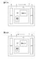
- FIG. 1 is a schematic diagram illustrating an inkjet printer according to an embodiment.
- 3A and 3B are diagrams illustrating an operation example of the ink jet printer in the mat-like image forming mode.
- FIG. 3A illustrates the forward path of the carriage
- FIG. 3B illustrates the backward path of the carriage.
- 4A and 4B are diagrams illustrating an operation example of the ink jet printer in the glossy image forming mode.
- FIG. 4A illustrates the forward path of the carriage
- FIG. 4B illustrates the backward path of the carriage.
- 5A and 5B are diagrams illustrating an operation example of the ink jet printer in the embossed image forming mode.
- FIG. 5A illustrates the forward path of the carriage
- FIG. 5B illustrates the backward path of the carriage
- 6A and 6B are diagrams showing another example of the operation of the ink jet printer in the embossed image forming mode.
- FIG. 6A shows the forward path of the carriage
- FIG. 6B shows the backward path of the carriage.
- the inkjet printer discharges ultraviolet curable ink as droplets, and irradiates the ultraviolet curable ink landed on the medium with ultraviolet rays to cure the image, so that an image having a matte, glossy, or textured texture can be obtained.
- An image forming apparatus for forming on a medium In the drawings, the same or corresponding parts are denoted by the same reference numerals.
- FIG. 1 is a diagram illustrating a configuration of an inkjet printer system including an inkjet printer according to an embodiment.
- an inkjet printer system 10 includes an inkjet printer 1 according to the present embodiment and an external device 20 such as a personal computer.
- the external device 20 includes an application 21 that creates image data of an image formed by the inkjet printer 1 and a RIP (Raster Image Processor) that generates print data for printing by the inkjet printer 1 based on the image data. 22 is incorporated.
- RIP Raster Image Processor
- FIG. 2 is a schematic view showing the ink jet printer according to the embodiment.
- the inkjet printer 1 according to the present embodiment includes a carriage 2 that can reciprocate in the scanning direction S, a head unit 3 that is mounted on the carriage 2 and has a plurality of inkjet heads 6 mounted thereon, and a carriage. 2, an ultraviolet irradiation device 4 mounted on the head unit 3 in the scanning direction S, an ultraviolet irradiation device 5 mounted on the carriage 2 and disposed in the scanning direction S behind the head unit 3, the carriage 2, And a control unit 8 that controls the inkjet head 6, the ultraviolet irradiation device 4, and the ultraviolet irradiation device 5.
- the ink jet printer 1 transports the medium in the feed direction F perpendicular to the scanning direction S by the path width, and moves the carriage 2 in the scanning direction S to eject ultraviolet curable ink from the ink jet head 6. At the same time, an image is formed on the medium by performing scanning that irradiates ultraviolet rays from the ultraviolet irradiation device 4 and the ultraviolet irradiation device 5.
- the present invention is not limited to the number of passes, in the present embodiment, a printing operation in the case of printing in two passes will be described as an example.
- the width (pass width) obtained by dividing the nozzle row of the inkjet head 6 by 2 that is the number of passes is defined as a single transport amount of the medium, and the same print area is printed twice (the number of passes). A printing operation will be described.
- the carriage 2 is movably held on a guide rail (not shown) extending in the scanning direction S above a platen (not shown) on which the medium is conveyed.
- the carriage 2 is mounted with a drive mechanism (not shown) such as a drive motor, and the drive mechanism can drive the carriage 2 to reciprocate in the scanning direction S along the guide rail.
- the drive mechanism need not be mounted on the carriage 2 and may be mounted on the inkjet printer 1 as a separate member from the carriage 2.
- drive control of the carriage 2 by the control unit 8 described later is drive control of a drive mechanism mounted on the ink jet printer 1 as a separate member from the carriage 2.
- the head unit 3 is an ink ejection device in which a plurality of inkjet heads 6 (6a to 6f) that eject ultraviolet curable ink are incorporated. Since the head unit 3 is mounted on the carriage 2, it is possible to discharge ultraviolet curable ink from each inkjet head 6 when moving in the scanning direction S accompanying the movement of the carriage 2.
- the ink jet head 6a to the ink jet head 6f are provided along the scanning direction S.
- the ink jet head 6a, the ink jet head 6b, the ink jet head 6c, the ink jet head 6d, and the ink jet are arranged from the front to the rear in the scanning direction S.
- the head 6e and the inkjet head 6f are arranged in this order.
- Each inkjet head 6 is formed with a plurality of nozzles (not shown) that discharge ultraviolet curable ink as droplets.
- the plurality of nozzles form a nozzle row arranged to extend in the feed direction F.
- Colored ultraviolet curable ink (hereinafter also referred to as “color ink”) is ejected from the inkjet head 6a to inkjet head 6d arranged on the front side in the scanning direction S, and the inkjet head arranged on the rear side in the scanning direction S.
- 6e and the inkjet head 6f discharge ultraviolet curable ink having translucency (hereinafter also referred to as “clear ink”). More specifically, black (K) color ink is ejected from the nozzle row of the inkjet head 6a.
- Yellow (Y) color ink is ejected from the nozzle row of the inkjet head 6b.
- Cyan (C) color ink is ejected from the nozzle row of the inkjet head 6c.
- Magenta (M) color ink is ejected from the nozzle row of the inkjet head 6d.
- clear ink (CL) is ejected from each nozzle row of the inkjet head 6e and the inkjet head 6f.
- the color ink is ejected only from the nozzle array of the first ejection region A1 arranged in the rear half in the feed direction F, and the feed Color ink is not ejected from the nozzle rows arranged in the front half in the direction F.
- the clear ink is ejected only from the nozzle row of the second ejection area A2 arranged in the front half in the feed direction F among the nozzle rows formed in the inkjet head 6e and the inkjet head 6f that eject the clear ink, and feed Clear ink is not ejected from the nozzle rows arranged in the rear half in the direction F.
- the color ink ejected from the first ejection area A1 of the inkjet head 6a to the inkjet head 6d is first applied to the surface of the media to be conveyed in the feed direction F, and then the media is fed in the feed direction F. Then, the clear ink ejected from the second ejection area A2 of the inkjet head 6e and the inkjet head 6f is applied to the surface (upper layer) of the color ink.
- the ultraviolet irradiation device 4 irradiates the ultraviolet curable ink applied to the medium with ultraviolet rays to cure the ultraviolet curable ink.
- the ultraviolet irradiation device 4 includes an ultraviolet light emitting diode (hereinafter referred to as “UVLED”) as a main component, and emits ultraviolet light when the UVLED is turned on, and stops emitting ultraviolet light when the UVLED is turned off.
- UVLED ultraviolet light emitting diode
- the UVLED is directed in the direction of the platen (not shown) through which the medium is conveyed.
- the UVLED is turned on, the medium conveyed to the platen is irradiated with ultraviolet light, and the UVLED is turned off. This stops the irradiation of the medium with ultraviolet rays.
- the ultraviolet irradiation device 4 is mounted on the carriage 2, it is possible to emit ultraviolet rays when reciprocating in the scanning direction S accompanying the movement of the carriage 2.
- the ultraviolet irradiating device 5 like the ultraviolet irradiating device 4, irradiates the ultraviolet curable ink applied to the medium with ultraviolet rays to cure the ultraviolet curable ink.
- the ultraviolet irradiation device 5 includes an ultraviolet light emitting diode (hereinafter referred to as “UVLED”) as a main component, and emits ultraviolet light when the UVLED is turned on, and stops emitting ultraviolet light when the UVLED is turned off.
- UVLED ultraviolet light emitting diode
- the UVLED is directed in the direction of a platen (not shown) through which the medium is conveyed.
- the UVLED is turned on, the ultraviolet light is irradiated to the medium conveyed to the platen, and the UVLED is turned off. This stops the irradiation of the medium with ultraviolet rays.
- the ultraviolet irradiation device 5 is mounted on the carriage 2, it is possible to emit ultraviolet rays when reciprocating in the scanning direction S accompanying the movement of the carriage 2.
- the control unit 8 performs print control of the inkjet printer 1 by controlling the carriage 2, the inkjet head 6, the ultraviolet irradiation device 4, and the ultraviolet irradiation device 5 in an integrated manner.
- the control unit 8 includes a mat-like image forming mode for forming a mat-like texture image, a gloss image forming mode for forming a glossy image, and a grain-like image forming mode for forming a texture-like image. And can be selectively switched. Note that the image forming mode may be selected based on print data transmitted from the RIP 22 or based on the settings of the inkjet printer 1.
- the control unit 8 performs drive control of the carriage 2, ink ejection control of the inkjet head 6, and ultraviolet irradiation control of the ultraviolet irradiation device 4 and the ultraviolet irradiation device 5 according to the selected image forming mode.
- a mat-like texture image, a glossy image, and a texture-like image can be formed respectively.
- the control unit 8 is configured mainly by a computer including a CPU, a ROM, and a RAM, for example. Each control of the control unit 8 to be described later reads predetermined computer software on the CPU or RAM, and Realized by operating under control.
- the RIP 22 generates dot format print data to be printed by the inkjet printer 1 based on image data such as EPS format or TIFF format created by the application 21, and transmits the print data to the inkjet printer 1.
- An image is formed on the inkjet printer 1.
- This print data is composed of whether or not UV curable ink is discharged, the number of times of UV curable ink discharge, the amount of UV curable ink discharged, and the like for each image of a predetermined resolution pitch.
- This print data is associated with each of the inkjet heads 6a to 6f, and each pixel of the print data is associated with each nozzle (not shown) in the first ejection area A1 and the second ejection area A2. It has been.
- the RIP 22 normally generates print data in which ultraviolet curable ink is ejected from all pixels, but can perform a thinning process for thinning out some pixels of the print data.
- the thinning-out process is a process of changing whether or not the ultraviolet curable ink is ejected from the presence to the absence for a predetermined pixel.
- the predetermined pixels to be thinned out may be specified by a predetermined mask, or may be specified by a random number, a predetermined mathematical expression, or the like.
- the thinning process may be performed after print data is generated, or may be performed when print data is generated.
- the thinning-out process will be described using print data that forms an image having a print density of 100% by discharging ultraviolet curable ink to all pixels.
- the print data before the thinning process is left as it is, whether or not the ultraviolet curable ink is ejected is set to “Yes” in all the pixels, and the ultraviolet curable ink is ejected to all the pixels. Therefore, for example, when 100% UV curable ink is ejected from both the inkjet head 6e and the inkjet head 6f in the second ejection area A2 based on the print data before the thinning process, the print density is increased. It becomes 200%, and the droplet density of the ultraviolet curable ink becomes substantially uniform.
- the ultraviolet curable ink ejected to the medium may be the ultraviolet curable ink for some pixels. Is not discharged, the printing density is less than 200%, and the droplet density of the ultraviolet curable ink becomes non-uniform.
- the RIP 22 transmits the generated print data to the inkjet printer 1 as it is.
- the RIP 22 transmits the generated print data to the inkjet printer 1 as the print data associated with the first discharge area A1, and the second discharge As the print data associated with the area A2, the print data subjected to the thinning process (print data in which the ultraviolet curable ink is not ejected from a part of the thinned pixels) is transmitted to the inkjet printer 1.
- the control unit 8 of the inkjet printer 1 transmits the RIP 22 from the first discharge area A1 and the second discharge area A2 in at least one of the forward path and the return path of the carriage 2.
- the ultraviolet curable ink is ejected based on the print data, and ultraviolet rays are emitted from one of the ultraviolet irradiating device 4 and the ultraviolet irradiating device 5 arranged at least behind the carriage 2 in the moving direction.
- ultraviolet rays are emitted from both the ultraviolet irradiation device 4 and the ultraviolet irradiation device 5 in both the forward and backward directions of the carriage 2.
- the control unit 8 performs UV curable ink based on print data transmitted from the RIP 22 from the first discharge area A1 and the second discharge area A2 in the forward path of the carriage 2.
- ultraviolet rays are emitted from at least one of the ultraviolet irradiation device 4 and the ultraviolet irradiation device 5.
- the control unit 8 sets the ejection amount based on the print data transmitted from the RIP 22 from the first ejection area A1 and the second ejection area A2 in the forward path of the carriage 2.
- the ultraviolet curable ink is changed and discharged, and ultraviolet rays are emitted from at least one of the ultraviolet irradiation device 4 and the ultraviolet irradiation device 5 in the return path of the carriage 2.
- ultraviolet curable ink is ejected from the second ejection area A2 based on the print data thinned out by the RIP 22 in the forward path of the carriage 2, and the ultraviolet irradiation device 4 is ejected in the return path of the carriage 2. It is assumed that ultraviolet rays are emitted from only from.
- FIGS. 3A and 3B are diagrams illustrating an operation example of the ink jet printer in the mat-like image forming mode.
- FIG. 3A illustrates the forward path of the carriage
- FIG. 3B illustrates the backward path of the carriage.
- 4A and 4B are diagrams illustrating an operation example of the ink jet printer in the glossy image forming mode.
- FIG. 4A illustrates the forward path of the carriage
- FIG. 4B illustrates the backward path of the carriage.
- 5A and 5B are diagrams illustrating an operation example of the ink jet printer in the embossed image forming mode.
- FIG. 5A illustrates the forward path of the carriage
- FIG. 5A illustrates the forward path of the carriage
- 5B illustrates the backward path of the carriage.
- a processing unit (not shown) constituted by a CPU or the like causes the carriage 2, the inkjet head 6, the ultraviolet irradiation device 4, and the ultraviolet irradiation device 5 to follow the program recorded in a storage device such as a ROM.
- the following processing is performed by centralized control.
- the RIP 22 In the matte image forming mode, first, the RIP 22 generates print data based on the image data generated by the application 21. At this time, the RIP 22 does not perform print data thinning-out processing. Then, the RIP 22 transmits this print data to the inkjet printer 1. On the other hand, when acquiring the print data transmitted from the RIP 22, the inkjet printer 1 scans the carriage 2 by reciprocating in the scanning direction S.
- the first ejection area A1 and the second ejection area A2 are driven by driving the first ejection area A1 and the second ejection area A2.
- a droplet of ultraviolet curable ink is ejected from the region A2, and the ultraviolet irradiation device 4 and the ultraviolet irradiation device 5 are turned on.
- the droplet-shaped ultraviolet curable ink discharged from the first discharge area A1 and the second discharge area A2 is irradiated with the ultraviolet rays emitted from the ultraviolet irradiation device 4 and the ultraviolet irradiation device 5 immediately after landing on the medium.
- the droplet-shaped ultraviolet curable ink that has landed on the medium is cured before being smoothed, so that a mat-like image is formed in which the surface is uneven and emits light.
- the RIP 22 In the glossy image forming mode, first, the RIP 22 generates print data based on the image data generated by the application 21.
- the RIP 22 has a discharge amount of 1400 to 3400 pg / mm 2 in one scan (1 pass) of the ultraviolet curable ink (clear ink) discharged from the inkjet head 6e and the inkjet head 6f in the second discharge area A2.
- the total discharge amount of the ultraviolet curable ink discharged from the inkjet head 6e and the inkjet head 6f is 2800 to 6800 pg / mm 2 .
- the total ejection amount of the ultraviolet curable ink ejected from the inkjet head 6e and the inkjet head 6f is several times the number of passes of 1400 to 3400 pg / mm 2 .
- the ultraviolet curable ink discharged from each of the inkjet head 6e and the inkjet head 6f is 16.8 to 40.8 ng / mm 2 , which is 12 times 1400 to 3400 pg / mm 2.
- the ultraviolet curable ink discharged from the inkjet head 6e and the inkjet head 6f is combined, it becomes 33.6 to 81.6 ng / mm 2 .
- the means for increasing the discharge amount of the ultraviolet curable ink per unit area may be any means, for example, each droplet discharged from the ink jet head 6e and the ink jet head 6f at a lower moving speed of the carriage 2.
- Means for increasing the appropriate amount of liquid means for increasing the discharge density of droplets discharged from the ink jet head 6e and the ink jet head 6f, means for increasing the number of ink jet heads mounted in the second discharge region A2, and the like.
- the discharge amount of the ultraviolet curable ink (color ink) discharged from the inkjet head 6a to the inkjet head 6d is appropriately set according to the color image to be formed.
- the RIP 22 transmits the print data to the inkjet printer 1 without performing the print data thinning process.
- the inkjet printer 1 scans the carriage 2 by reciprocating in the scanning direction S.
- the first ejection area A1 and the second ejection area A2 are driven to drive the first ejection area A1 and the second ejection area A2.
- the droplets of the ultraviolet curable ink are ejected from the region A2, and the ultraviolet irradiation device 4 and the ultraviolet irradiation device 5 are turned off.
- the inkjet head 6e and the inkjet head 6f are set so that the ejection amounts of the clear ink ejected from the inkjet head 6e and the inkjet head 6f in the second ejection area A2 are 1400 to 3400 pg / mm 2 , respectively.
- the total discharge amount of the ultraviolet curable ink discharged from both the inkjet head 6e and the inkjet head 6f in one scan (1 pass) is 2800 to 6800 pg / mm 2 .
- the droplet-shaped ultraviolet curable ink ejected from the second ejection area A2 has landed on the medium, it gradually wets and spreads on the medium to reduce the thickness, and the surface unevenness is smoothed.
- the total discharge amount of UV curable ink is 2800-6800 pg / mm 2 and the droplet density of UV curable ink is high, so contact and mixing are likely to occur between adjacent droplets, facilitating smoothing. Is done.
- the driving of the first discharge area A1 and the second discharge area A2 is stopped to stop the discharge of the ultraviolet curable ink.
- the ultraviolet irradiation device 4 is turned on and the ultraviolet irradiation device 5 is turned off. Then, the ultraviolet curable ink ejected in the forward path of the carriage 2 and landed on the medium is irradiated with ultraviolet rays, and the ultraviolet curable ink is cured.
- the ultraviolet curable ink is ejected in the forward path of the carriage 2
- the ultraviolet curable ink landed on the medium is sufficiently smoothed until the ultraviolet ray is irradiated on the return path. Since the ultraviolet curable ink is cured in such a smoothed state, a glossy image is formed.
- the RIP 22 In the textured image forming mode, first, the RIP 22 generates print data based on the image data generated by the application 21. At this time, the RIP 22 performs a thinning process on the print data associated with the second ejection area A2. Then, the RIP 22 transmits this print data to the inkjet printer 1. On the other hand, when acquiring the print data transmitted from the RIP 22, the inkjet printer 1 scans the carriage 2 by reciprocating in the scanning direction S.
- the first ejection area A1 is driven, and the ultraviolet curable ink is driven from the first ejection area A1 based on the print data.
- the second ejection area A2 is driven, and ultraviolet curable ink droplets are ejected from the second ejection area A2 based on the print data thinned out.
- the device 5 is turned off. Then, from the second ejection area A2, pixels are thinned out and ultraviolet curable ink droplets are ejected, and ultraviolet curable ink is not ejected to the thinned pixels.
- the droplet-shaped ultraviolet curable ink ejected from the first ejection area A1 and the second ejection area A2 is gradually spread on the medium after landing on the medium, as in the glossy image forming mode. Get smaller.
- the ultraviolet curable ink is not ejected from the thinned out pixels in the second ejection area A2
- the droplet density of the ultraviolet curable ink on the medium is made non-uniform.
- the smoothness of the ultraviolet curable ink becomes non-uniform depending on the location. For this reason, the droplet-shaped ultraviolet curable ink that has landed on the medium has moderate irregularities while being smoothed.
- the driving of the first ejection area A1 and the second ejection area A2 is stopped to stop the ejection of the ultraviolet curable ink.
- the ultraviolet irradiation device 4 is turned on and the ultraviolet irradiation device 5 is turned off.
- the ultraviolet curable ink ejected in the forward path of the carriage 2 and landed on the medium is irradiated with ultraviolet rays, and the ultraviolet curable ink is cured.
- the ultraviolet curable ink is ejected in the forward path of the carriage 2, While being smoothed, moderate unevenness is generated before the ultraviolet ray is irradiated on the return path. Since the ultraviolet curable ink is cured in a state where moderate irregularities are generated in this way, an image with a textured texture is formed.
- the matte image forming mode, the glossy image forming mode, and the textured image forming mode are selectively switched, and the first discharge area A1, the second discharge area A2, the ultraviolet irradiation device 4, and the like.
- the UV irradiation device 5 By controlling the UV irradiation device 5 according to each image forming mode, it is possible to form matte, glossy, and textured images with one type of UV curable ink without changing the type of UV curable ink. It becomes possible to do.
- the image forming speed can be increased by discharging the ultraviolet curable ink from both the first discharge area A1 and the second discharge area A2.
- smoothing of the ultraviolet curable ink can be promoted by increasing the discharge amount of the ultraviolet curable ink in one scan.
- the embossed image forming mode is selected, the droplet density of the droplet-shaped ultraviolet curable ink landed on the medium is reduced by thinning pixels from the second ejection area A2 and ejecting the ultraviolet curable ink. Can be non-uniform. As a result, moderate unevenness can be generated while smoothing the droplet-shaped ultraviolet curable ink that has landed on the medium, so that a texture-like image can be appropriately formed.
- the discharge amount of the ultraviolet curable ink discharged in one scan from each inkjet head 6 in the second discharge region A2 arranged behind the scan direction S is set to 1400 per unit area.
- the adjacent ultraviolet curable ink droplets that have landed on the medium are easily mixed with each other, so that the smoothing of the ultraviolet curable ink can be promoted.
- the unevenness of the ultraviolet curable ink that has landed on the medium can be sufficiently smoothed while the carriage reciprocates.
- UV LEDs for the ultraviolet irradiation device 4 and the ultraviolet irradiation device 5
- the ultraviolet ray can be emitted only when the ultraviolet ray is necessary, and energy saving can be achieved.
- the present invention has been described above, but the present invention is not limited to the above embodiment.
- ultraviolet curable ink in the matte image forming mode, it has been described that ultraviolet curable ink is ejected in both the forward path and the backward path of the carriage 2, but for example, as shown in FIGS. 6A and 6B, The ultraviolet curable ink may be ejected only in any one of the return paths.
- the first ejection area A1 and the second ejection area A2 are driven by driving the first ejection area A1 and the second ejection area A2, as shown in FIG. 6A.
- the droplets of the ultraviolet curable ink are ejected from the ejection region A2, and the ultraviolet irradiation device 4 and the ultraviolet irradiation device 5 are turned on.
- the driving of the first ejection area A1 and the second ejection area A2 is stopped, and the ultraviolet irradiation device 4 and the ultraviolet irradiation are performed.
- the device 5 is turned on. The reason why the ultraviolet rays are irradiated on the return path of the carriage 2 is to promote the curing of the ultraviolet curable ink, so that it is not necessary to irradiate the ultraviolet rays particularly on the return path of the carriage 2.
- control unit 8 thins out pixels and discharges the ultraviolet curable ink from the second discharge area A2 by performing the print data thinning process in the RIP 22.
- control unit 8 may perform print data thinning processing.
- the amount of ultraviolet curable ink discharged from the inkjet head 6 is discharged by thinning pixels from the second discharge region A2 and discharging droplets of the ultraviolet curable ink.
- the discharge amount of the ultraviolet curable ink discharged from the second discharge region A2 may be changed by any means.
- the discharge amount of the ultraviolet curable ink in each pixel may be increased or decreased.
- the first discharge area A1 that discharges color ink is the second half nozzle array in the feed direction F
- the second discharge area A2 that discharges clear ink is in the feed direction F of the inkjet head 6.
- the first ejection region A1 and the second ejection region A2 may be the entire nozzle row. In this case, since the first ejection area A1 and the second ejection area A2 are in the same position in the feed direction F, the color ink ejection and the clear ink ejection are performed separately.
- the medium is conveyed in the feed direction F, the color ink is ejected from the first ejection area A1 to print a color image, and then the media is fed back once. Then, the medium is conveyed again in the feed direction F, the clear ink is ejected from the second ejection area A2, and the clear ink is applied to the surface of the color image.
- the second discharge area A2 that is, the inkjet head 6e and the ink jet head 6e, without discharging the color ink from the first discharge area A1. This is performed by discharging clear ink from the entire nozzle array in the inkjet head 6f.
- the ultraviolet curable ink is ejected only from the first ejection area A1 and the second ejection area A2 of the inkjet head 6.
- 5% by volume or less of color ink may be ejected from the area disposed in the front half in the feed direction F with respect to the clear ink ejected from the second ejection area A2. Accordingly, since the clear ink is mixed with 5% by volume or less of color ink in one scan, a colored clear ink coating film can be formed.
- the head unit 3 has been described as having only one set of ink jet heads for discharging color ink, but a plurality of sets of ink colors may be mounted.
- the switching operation from the forward movement to the backward movement of the carriage 2 is not particularly specified.
- the backward movement may be started after waiting for a predetermined time after the forward movement of the carriage 2 is finished. Thereby, since the ultraviolet curable ink spreads more wet, smoothing can be further promoted.
- the number of passes is not limited.
- the width (pass width) obtained by dividing the nozzle row of the inkjet head 6 by 12 that is the number of passes is defined as a single transport amount of the medium, and the same print area is set to 12 times (number of passes). ) Scan.
- the UV LED is used as the ultraviolet irradiation device.
- any type of metal halide lamp may be used as long as the ultraviolet curable ink can be irradiated with ultraviolet rays.
- a metal halide lamp it is possible to select whether to irradiate ultraviolet rays by providing a shutter and a shutter opening / closing device.
Landscapes
- Health & Medical Sciences (AREA)
- General Health & Medical Sciences (AREA)
- Toxicology (AREA)
- Engineering & Computer Science (AREA)
- Quality & Reliability (AREA)
- Ink Jet (AREA)
- Ink Jet Recording Methods And Recording Media Thereof (AREA)
Abstract
Description
マット状画像形成モードでは、まず、RIP22が、アプリケーション21で生成された画像データに基づいて印刷データを生成する。このとき、RIP22は、印刷データの間引き処理を行わない。そして、RIP22は、この印刷データをインクジェットプリンタ1に送信する。一方、インクジェットプリンタ1は、RIP22から送信された印刷データを取得すると、キャリッジ2を走査方向Sにおいて往復移動させてスキャンする。
Claims (6)
- 紫外線硬化型インクを液滴として吐出して記録媒体に画像を形成する画像形成装置であって、
走査方向において往復移動可能なキャリッジに搭載されて紫外線硬化型インクを吐出するインク吐出手段と、
前記キャリッジに搭載されるとともに少なくとも前記インク吐出手段の走査方向後方に配置されて前記インク吐出手段から吐出された紫外線硬化型インクに紫外線を照射する紫外線照射手段と、
前記インク吐出手段及び前記紫外線照射手段を制御する制御手段と、
を備え、
前記制御手段は、
前記キャリッジの往路及び復路の少なくとも一方において、前記インク吐出手段に紫外線硬化型インクを吐出させるとともに、前記紫外線照射手段から紫外線を照射させる、マット状画像形成モードと、
前記キャリッジの往路において、前記インク吐出手段に紫外線硬化型インクを吐出させ、前記キャリッジの復路において、前記紫外線照射手段から紫外線を照射させる、光沢画像形成モードと、
前記キャリッジの往路において、前記インク吐出手段に吐出量を変化させて紫外線硬化型インクを吐出させ、前記キャリッジの復路において、前記紫外線照射手段から紫外線を照射させる、シボ状画像形成モードと、
を選択的に切替可能であることを特徴とする画像形成装置。 - 前記インク吐出手段は、第一インク吐出手段と、前記第一インク吐出手段の走査方向後方に配置される第二インク吐出手段と、を備えることを特徴とする請求項1に記載の画像形成装置。
- 前記制御部は、
前記シボ状画像形成モードを選択する場合、前記第二インク吐出手段に画素を間引いて紫外線硬化型インクを吐出させることを特徴とする請求項2に記載の画像形成装置。 - 前記制御部は、
前記光沢画像形成モードを選択する場合、前記第二インク吐出手段による紫外線硬化型インクの1走査における吐出量を1400~3400pg/mm2とすることを特徴とする請求項2又は3に記載の画像形成装置。 - 前記紫外線照射手段は、紫外線発光ダイオードを備えることを特徴とする請求項1項に記載の画像形成装置。
- 走査方向において往復移動可能なキャリッジに搭載されて紫外線硬化型インクを液滴として吐出するインク吐出手段と、前記キャリッジに搭載されるとともに前記インク吐出手段の走査方向後方に配置されて前記インク吐出手段から吐出された紫外線硬化型インクに紫外線を照射する紫外線照射手段と、前記インク吐出手段及び前記紫外線照射手段を制御する制御手段と、備える画像形成装置により記録媒体に画像を形成する画像形成方法であって、
マット状の画像を形成する場合は、前記キャリッジの往路及び復路の少なくとも一方において、前記インク吐出手段に紫外線硬化型インクを吐出させるとともに、前記紫外線照射手段から紫外線を照射させ、
光沢感のある画像を形成する場合は、前記キャリッジの往路において、前記インク吐出手段に紫外線硬化型インクを吐出させ、前記キャリッジの復路において、前記紫外線照射手段から紫外線を照射させ、
シボ状の画像を形成する場合は、前記キャリッジの往路において、前記インク吐出手段に吐出量を変化させて紫外線硬化型インクを吐出させ、前記キャリッジの復路において、前記紫外線照射手段から紫外線を照射させることを特徴とする画像形成方法。
Priority Applications (2)
| Application Number | Priority Date | Filing Date | Title |
|---|---|---|---|
| JP2011553888A JP5391494B2 (ja) | 2010-02-12 | 2011-02-10 | 画像形成装置及び画像形成方法 |
| CN201180018933.8A CN102858543B (zh) | 2010-02-12 | 2011-02-10 | 图像形成装置以及图像形成方法 |
Applications Claiming Priority (2)
| Application Number | Priority Date | Filing Date | Title |
|---|---|---|---|
| JP2010-029108 | 2010-02-12 | ||
| JP2010029108 | 2010-02-12 |
Publications (1)
| Publication Number | Publication Date |
|---|---|
| WO2011099560A1 true WO2011099560A1 (ja) | 2011-08-18 |
Family
ID=44367830
Family Applications (1)
| Application Number | Title | Priority Date | Filing Date |
|---|---|---|---|
| PCT/JP2011/052864 Ceased WO2011099560A1 (ja) | 2010-02-12 | 2011-02-10 | 画像形成装置及び画像形成方法 |
Country Status (3)
| Country | Link |
|---|---|
| JP (1) | JP5391494B2 (ja) |
| CN (1) | CN102858543B (ja) |
| WO (1) | WO2011099560A1 (ja) |
Cited By (1)
| Publication number | Priority date | Publication date | Assignee | Title |
|---|---|---|---|---|
| US9457607B2 (en) | 2014-06-23 | 2016-10-04 | Mimaki Engineering Co., Ltd. | Image forming method |
Families Citing this family (6)
| Publication number | Priority date | Publication date | Assignee | Title |
|---|---|---|---|---|
| CN105751717B (zh) * | 2014-12-17 | 2018-03-16 | 上海泰威技术发展股份有限公司 | 紫外灯输出功率的控制方法及应用其的喷绘打印装置 |
| CN105172392B (zh) * | 2015-08-25 | 2017-10-24 | 深圳市汉拓数码有限公司 | 紫外灯固化装置及其固化方法 |
| EP3437887B1 (en) * | 2017-07-31 | 2022-03-30 | HP Scitex Ltd | Method and printing system for depositing printing fluid on a sheet of corrugated media |
| CN112752653B (zh) | 2018-09-27 | 2022-07-12 | 富士胶片株式会社 | 装饰部件制造装置及装饰部件制造方法 |
| JP7424857B2 (ja) * | 2020-02-17 | 2024-01-30 | 株式会社ミマキエンジニアリング | インクジェットプリンタ |
| CN112373194B (zh) * | 2020-11-24 | 2025-02-18 | 北京美科艺数码科技发展有限公司 | 一种喷墨打印装置及其固化方法 |
Citations (3)
| Publication number | Priority date | Publication date | Assignee | Title |
|---|---|---|---|---|
| JP2006289722A (ja) * | 2005-04-08 | 2006-10-26 | Konica Minolta Medical & Graphic Inc | インクジェット記録装置及びインクジェット記録方法 |
| JP2007144849A (ja) * | 2005-11-29 | 2007-06-14 | Konica Minolta Medical & Graphic Inc | インクジェット記録装置 |
| WO2009148074A1 (ja) * | 2008-06-03 | 2009-12-10 | ローランドディー.ジー.株式会社 | インクジェット式記録装置 |
Family Cites Families (2)
| Publication number | Priority date | Publication date | Assignee | Title |
|---|---|---|---|---|
| JP2005074878A (ja) * | 2003-09-02 | 2005-03-24 | Konica Minolta Medical & Graphic Inc | 画像記録装置 |
| JP4470495B2 (ja) * | 2004-01-15 | 2010-06-02 | コニカミノルタエムジー株式会社 | 画像記録装置 |
-
2011
- 2011-02-10 WO PCT/JP2011/052864 patent/WO2011099560A1/ja not_active Ceased
- 2011-02-10 CN CN201180018933.8A patent/CN102858543B/zh active Active
- 2011-02-10 JP JP2011553888A patent/JP5391494B2/ja active Active
Patent Citations (3)
| Publication number | Priority date | Publication date | Assignee | Title |
|---|---|---|---|---|
| JP2006289722A (ja) * | 2005-04-08 | 2006-10-26 | Konica Minolta Medical & Graphic Inc | インクジェット記録装置及びインクジェット記録方法 |
| JP2007144849A (ja) * | 2005-11-29 | 2007-06-14 | Konica Minolta Medical & Graphic Inc | インクジェット記録装置 |
| WO2009148074A1 (ja) * | 2008-06-03 | 2009-12-10 | ローランドディー.ジー.株式会社 | インクジェット式記録装置 |
Cited By (1)
| Publication number | Priority date | Publication date | Assignee | Title |
|---|---|---|---|---|
| US9457607B2 (en) | 2014-06-23 | 2016-10-04 | Mimaki Engineering Co., Ltd. | Image forming method |
Also Published As
| Publication number | Publication date |
|---|---|
| CN102858543A (zh) | 2013-01-02 |
| JPWO2011099560A1 (ja) | 2013-06-17 |
| CN102858543B (zh) | 2015-08-26 |
| JP5391494B2 (ja) | 2014-01-15 |
Similar Documents
| Publication | Publication Date | Title |
|---|---|---|
| JP5453681B2 (ja) | 画像形成装置及び画像形成方法 | |
| JP4026652B2 (ja) | インクジェット記録装置及びインクジェット記録方法 | |
| JP5421323B2 (ja) | インクジェット記録装置及び画像形成方法 | |
| US8424993B2 (en) | Ink jet type recording device and computer program | |
| JP5391494B2 (ja) | 画像形成装置及び画像形成方法 | |
| JP5845620B2 (ja) | 液体吐出装置 | |
| JP5247895B2 (ja) | インクジェットプリンタ | |
| JP2011073330A (ja) | 印刷装置、及び、印刷方法 | |
| WO2009148074A1 (ja) | インクジェット式記録装置 | |
| JP5668462B2 (ja) | 印刷装置及び印刷方法 | |
| JPWO2012053647A1 (ja) | インクジェット記録装置 | |
| JP5378194B2 (ja) | インクジェット式画像形成装置 | |
| JP5848683B2 (ja) | 画像形成装置及び画像形成方法 | |
| JP2009051094A (ja) | インクジェット記録装置 | |
| JP5617588B2 (ja) | 印刷装置及び印刷方法 | |
| JP2018024164A (ja) | 印刷装置及び印刷方法 | |
| US12257766B2 (en) | Shaping apparatus and shaping method | |
| JP5790098B2 (ja) | 液体吐出装置、及び、液体吐出方法 | |
| JP2011161824A (ja) | インクジェットプリンタ及び印刷方法 | |
| JP2013132791A (ja) | 印刷装置、及び、印刷方法 | |
| JP7158439B2 (ja) | インクジェットプリンタ | |
| JP2023077760A (ja) | プリンタ、制御方法、及び制御プログラム | |
| JP2012091457A (ja) | 画像形成装置及び仮硬化用の活性光線照射装置並びに照度分布の変更方法 | |
| JP2021165008A (ja) | インクジェット方式の印刷装置 |
Legal Events
| Date | Code | Title | Description |
|---|---|---|---|
| WWE | Wipo information: entry into national phase |
Ref document number: 201180018933.8 Country of ref document: CN |
|
| 121 | Ep: the epo has been informed by wipo that ep was designated in this application |
Ref document number: 11742303 Country of ref document: EP Kind code of ref document: A1 |
|
| WWE | Wipo information: entry into national phase |
Ref document number: 2011553888 Country of ref document: JP |
|
| NENP | Non-entry into the national phase |
Ref country code: DE |
|
| 122 | Ep: pct application non-entry in european phase |
Ref document number: 11742303 Country of ref document: EP Kind code of ref document: A1 |