WO2011099274A1 - 開口部の閉塞部材 - Google Patents
開口部の閉塞部材 Download PDFInfo
- Publication number
- WO2011099274A1 WO2011099274A1 PCT/JP2011/000712 JP2011000712W WO2011099274A1 WO 2011099274 A1 WO2011099274 A1 WO 2011099274A1 JP 2011000712 W JP2011000712 W JP 2011000712W WO 2011099274 A1 WO2011099274 A1 WO 2011099274A1
- Authority
- WO
- WIPO (PCT)
- Prior art keywords
- opening
- closing member
- panel
- composite material
- clamp member
- Prior art date
Links
- 239000002131 composite material Substances 0.000 claims abstract description 27
- 229920000049 Carbon (fiber) Polymers 0.000 claims description 28
- 239000004917 carbon fiber Substances 0.000 claims description 28
- VNWKTOKETHGBQD-UHFFFAOYSA-N methane Chemical compound C VNWKTOKETHGBQD-UHFFFAOYSA-N 0.000 claims description 20
- 230000002093 peripheral effect Effects 0.000 claims description 16
- 239000007769 metal material Substances 0.000 claims description 9
- 229910001069 Ti alloy Inorganic materials 0.000 claims description 6
- 239000002828 fuel tank Substances 0.000 claims description 5
- 229910045601 alloy Inorganic materials 0.000 claims description 3
- 239000000956 alloy Substances 0.000 claims description 3
- 239000004020 conductor Substances 0.000 abstract description 3
- 239000000853 adhesive Substances 0.000 description 7
- 230000001070 adhesive effect Effects 0.000 description 7
- 230000000903 blocking effect Effects 0.000 description 5
- 239000000463 material Substances 0.000 description 5
- 239000004918 carbon fiber reinforced polymer Substances 0.000 description 3
- 238000012423 maintenance Methods 0.000 description 3
- 229910052751 metal Inorganic materials 0.000 description 3
- 239000002184 metal Substances 0.000 description 3
- 238000010891 electric arc Methods 0.000 description 2
- 238000007689 inspection Methods 0.000 description 2
- 239000011810 insulating material Substances 0.000 description 2
- 229910000838 Al alloy Inorganic materials 0.000 description 1
- 239000004593 Epoxy Substances 0.000 description 1
- RTAQQCXQSZGOHL-UHFFFAOYSA-N Titanium Chemical compound [Ti] RTAQQCXQSZGOHL-UHFFFAOYSA-N 0.000 description 1
- 239000011248 coating agent Substances 0.000 description 1
- 238000000576 coating method Methods 0.000 description 1
- 239000003365 glass fiber Substances 0.000 description 1
- 230000005484 gravity Effects 0.000 description 1
- 238000009434 installation Methods 0.000 description 1
- 229910001256 stainless steel alloy Inorganic materials 0.000 description 1
- 239000010936 titanium Substances 0.000 description 1
- 229910052719 titanium Inorganic materials 0.000 description 1
Images

Classifications
-
- B—PERFORMING OPERATIONS; TRANSPORTING
- B64—AIRCRAFT; AVIATION; COSMONAUTICS
- B64C—AEROPLANES; HELICOPTERS
- B64C3/00—Wings
- B64C3/34—Tanks constructed integrally with wings, e.g. for fuel or water
-
- B—PERFORMING OPERATIONS; TRANSPORTING
- B64—AIRCRAFT; AVIATION; COSMONAUTICS
- B64D—EQUIPMENT FOR FITTING IN OR TO AIRCRAFT; FLIGHT SUITS; PARACHUTES; ARRANGEMENT OR MOUNTING OF POWER PLANTS OR PROPULSION TRANSMISSIONS IN AIRCRAFT
- B64D37/00—Arrangements in connection with fuel supply for power plant
- B64D37/32—Safety measures not otherwise provided for, e.g. preventing explosive conditions
-
- B—PERFORMING OPERATIONS; TRANSPORTING
- B64—AIRCRAFT; AVIATION; COSMONAUTICS
- B64D—EQUIPMENT FOR FITTING IN OR TO AIRCRAFT; FLIGHT SUITS; PARACHUTES; ARRANGEMENT OR MOUNTING OF POWER PLANTS OR PROPULSION TRANSMISSIONS IN AIRCRAFT
- B64D45/00—Aircraft indicators or protectors not otherwise provided for
- B64D45/02—Lightning protectors; Static dischargers
Definitions
- the present invention relates to a closing member for an opening provided in an aircraft body.
- the main wing of an aircraft has a hollow structure by attaching wing surface panels that form wing surfaces above and below a girder.
- the internal space of the main wing is a fuel tank.
- An opening is formed on the surface of the main wing in order to perform inspection and maintenance work inside the fuel tank. Under normal conditions, the opening is closed by the access door, and the access door is opened when performing inspection and maintenance work. (For example, refer to Patent Document 1).
- the access door includes a door body disposed on the inner space side of the main wing with respect to the opening, and a clamp ring disposed on the outer side of the main wing.
- Each of the door body and the clamp ring has a larger outer dimension than the opening.
- the door body and the clamp ring are fastened by a fastener member or the like with the periphery of the opening sandwiched between the outer periphery of the door body and the outer periphery of the clamp ring, thereby closing the opening by the door body. To do.
- a composite material using carbon fibers allows a current to flow, though only slightly. Regardless of the material forming the access door, it is necessary to ensure electrical bonding between the access door and the wing panel in order to prevent the access door from being electrically isolated.
- the material that forms the door body and clamp ring is a metal that can be regarded as the same type of metal as the carbon fiber composite material when electrical bonding is to be secured at the contact surface.
- Titanium alloy, CRES and the like Titanium alloy, CRES and the like.
- both titanium alloys and CRES are difficult-to-work materials, and further, titanium alloys are expensive, and CRES has a problem of large specific gravity and an increase in weight.
- the present invention has been made based on such a technical problem, and an object of the present invention is to provide an opening closing member having excellent lightning resistance.
- the present invention made for this purpose is a closing member for an opening formed in a panel made of a composite material containing carbon fibers constituting the outer surface of an aircraft body, and the closing member is at least the body of the aircraft.
- the side facing the outer side is formed of any one of a titanium alloy, a stainless alloy, and a composite material including carbon fiber, and is disposed on one side of the panel and has an outer diameter dimension larger than the opening.
- the closure member main body that closes the portion and at least the side facing the outside of the machine body is formed of a composite material including carbon fiber, and is disposed on the other surface side of the panel, and has a larger outer diameter than the opening.
- the portion of the clamp member that contacts the panel that forms the outer surface of the fuselage is formed of the same carbon fiber composite material as that of the panel, so that a metal that is electrically related to the carbon fiber composite material such as titanium or CRES can be made. Compared to the case where it is used, it is possible to ensure electrical bonding at a low cost and light weight.
- the abutting surface between the closing member main body and the inner peripheral portion of the clamp member, and the abutting surface between the outer peripheral portion of the clamp member and the inner peripheral edge of the opening are tapered surfaces inclined with respect to the direction perpendicular to the body surface. preferable.
- the clamp member may be formed of a composite material containing carbon fiber on the surface facing the outside of the airframe and a metal material on the surface facing the inside of the airframe.
- the opening provided with such a blocking member may have any application and configuration, but the opening is provided in the main wing constituting the fuselage and is an entrance to a fuel tank provided in the main wing. This is particularly preferable because the occurrence of arc discharge can be suppressed.
- the closing member when lightning strikes the closing member directly, an electric current can be passed to the panel around the opening through the carbon fiber constituting the clamp member. As a result, the closing member can be excellent in lightning resistance.
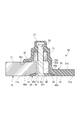
- FIG. 1 It is a perspective view which shows the access door provided in the main wing of the aircraft in this Embodiment. It is sectional drawing which shows the attachment structure of the access door with respect to the wing
- FIG. 1 is a perspective view of an access door (blocking member) 20 provided on a main wing 10 constituting a fuselage of an aircraft to which an opening blocking member according to the present embodiment is applied, as viewed from the inside of the main wing 10.
- the access door 20 is provided on a wing surface panel (panel) 11 that forms the upper or lower surface of the main wing 10 so that maintenance personnel can enter and leave the fuel tank provided in the internal space of the main wing 10. .
- the blade surface panel 11 is formed with an opening 12 that communicates the inside and outside of the main wing 10.
- the opening 12 may have an appropriate shape such as an ellipse, an ellipse, or a circle.
- the access door 20 includes a door main body (closing member main body) 30 disposed on the inner space side of the main wing 10 with respect to the opening 12, a clamp ring (clamp member) 40 disposed on the outer side of the main wing 10, and these It is comprised from the fastener member (fastener) 50 which fastens the door main body 30 and the clamp ring 40. As shown in FIG.
- the door body 30 has a larger outer dimension than the opening 12.
- the door body 30 has an outer surface 31 a that forms a continuous surface with the wing outer surface 11 a of the wing surface panel 11, a plate portion 31 having an outer dimension smaller than the opening 12, and an outer peripheral portion of the plate portion 31. And a flange portion 32 that abuts the periphery of the opening 12 on the inner space side of the main wing 10.
- the flange portion 32 is a receiving surface 32a that hits the periphery of the opening 12 on the inner space side of the main wing 10, and a receiving portion of the fastener member 50 that is formed at a portion facing the clamp ring 40 inside the contacting surface 32a. Part 33.
- a plurality of receiving portions 33 are provided along the circumferential direction of the outer peripheral portion of the door main body 30 corresponding to the installation positions of the fastener members 50.
- Each receiving portion 33 protrudes toward the inner space side of the main wing 10, and a recessed portion 33 a that opens to the side facing the clamp ring 40 is formed.
- the axial part 52a of the fastener main body 52 which comprises the fastener member 50 is accommodated.
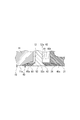
- the clamp ring 40 has a ring shape having an outer diameter larger than the inner diameter dimension of the opening 12 and an inner diameter smaller than the inner diameter dimension of the opening 12.
- the clamp ring 40 has a quadrangular cross section, and an outer surface 40a that is the outer side of the main wing 10 forms a surface that is continuous with the outer surface 11a of the wing surface panel 11 and faces the receiving portion 33 of the door body 30. 40b is formed in parallel with the outer surface 40a.
- a through hole 41 that penetrates the outer surface 40 a and the opposing surface 40 b is formed at a position corresponding to the receiving portion 33 of the door body 30.
- the shaft portion 52 a of the fastener member 50 is inserted into each through hole 41.
- a tapered seat surface 42 that accommodates the head portion 52 c of the fastener member 50 is formed on the side facing the outer surface of the main wing 10.
- the clamp ring 40 is trapezoidal in cross section, and tapered surfaces 40c and 40d are formed between the outer surface 40a and the opposing surface 40b. These tapered surfaces 40c and 40d are inclined so that the distance between them gradually increases from the facing surface 40b side toward the outer surface 40a side.
- a contact surface 34 is formed on the outer peripheral portion of the plate portion 31 so as to be in contact with the tapered surface 40 c on the inner peripheral side of the clamp ring 40.
- the contact surface 34 is formed on the tapered surface 40c of the clamp ring 40 so that the outer diameter of the plate portion 31 gradually increases from the outer surface 31a toward the inner surface 31b facing the inner side of the main wing 10. Inclined at a corresponding angle.
- a contact surface 14 is formed on the inner peripheral portion of the opening 12 of the wing surface panel 11 and hits the tapered surface 40d on the outer peripheral side of the clamp ring 40.
- the contact surface 14 is formed to be inclined at an angle corresponding to the tapered surface 40 d of the clamp ring 40.
- Such an access door 20 sandwiches the inner peripheral edge of the opening 12 between the abutting surface 32a of the flange 32 of the door body 30 and the clamp ring 40 when the opening 12 is closed. Then, the fastener body 52 of the fastener member 50 is inserted into the through hole 41 of the clamp ring 40 from the outside of the main wing 10, and the shaft body 52 a is screwed into the nut 51, whereby the door body 30 and the clamp ring 40 are fastened. . In this state, the contact surface 14 of the opening 12 and the tapered surface 40d of the clamp ring 40 abut, and the tapered surface 40c of the clamp ring 40 and the contact surface 34 of the plate portion 31 of the door body 30 abut.
- the door body 30 is formed of at least one of CFRP (composite material), titanium alloy, and CRES (stainless alloy) using carbon fiber on the side facing the outer side of the airframe. ing.
- CFRP composite material
- titanium alloy titanium alloy
- CRES stainless alloy
- the clamp ring 40 is formed of CFRP (composite material) using carbon fiber.
- CFRP composite material
- end portions of conductive carbon fibers provided in a direction along the surface of the main wing 10 are exposed.
- the clamp ring 40 has an outer surface 40 a facing the outside of the main wing 10 formed by a composite material layer 60 made of CFRP using carbon fiber, and faces the receiving portion 33 of the door body 30.
- the opposing surface 40b can also be a hybrid structure formed by a metal material layer 61 made of an aluminum alloy or the like.
- the composite material layer 60 and the metal material layer 61 have a laminated structure in which the composite material layer 60 and the metal material layer 61 are integrally joined by an adhesive 62 made of, for example, an insulating epoxy-based material.
- an insulating film (not shown) is formed on the composite material layer 60 by baking glass fibers (insulating material) on the adhesive surface side of the adhesive 62.
- An insulating film (not shown) is formed on the metal material layer 61 by coating an insulating material on the adhesive surface side of the adhesive 62.
- An insulating layer can be formed by the insulating film of the composite material layer 60, the adhesive 62, and the insulating film of the metal material layer 61.
- the tapered surfaces 40c and 40d of the clamp ring 40 are inclined surfaces, the main wing 10 constituting the entire clamp ring 40 (in the case of the configuration of FIG. 2) or the composite material layer 60 (in the case of the configuration of FIG. 3).
- the ends of the carbon fibers having a conductive material provided in the direction along the surface are exposed on the tapered surfaces 40c and 40d.
- the wing surface panel 11 is formed, and the end of the carbon fiber having conductivity is provided in the direction along the surface of the main wing 10.
- the door body 30, the clamp ring 40, and the opening portion 12 of the wing surface panel 11 are in contact with the contact surface 34 of the door body 30 and the taper surface 40 c of the clamp ring 40, and the taper surface of the clamp ring 40.
- 40d and the contact surface 14 of the opening part 12 are electrically connected by surface bonding between conductive materials.
- the contact surface 34 of the door body 30, the tapered surfaces 40c and 40d of the clamp ring 40, and the contact surface 14 of the opening 12 are, for example, the attaching / detaching direction of the door body 30 and the clamp ring 40, that is, the door body 30 and the wing surface panel. 11, the ends of the carbon fibers exposed on these surfaces may be rubbed and loosened as the door body 30 and the clamp ring 40 are repeatedly attached and detached. On the other hand, by making these surfaces into tapered surfaces, it is possible to prevent the carbon fibers from being loosened. Furthermore, because of the surface contact between the tapered surfaces, a large amount of carbon fiber cut surfaces are exposed on the tapered surface 40 d of the clamp ring 40 and the contact surface 14 of the opening 12. Thereby, the contact area between the carbon fibers of the tapered surface 40d of the clamp ring 40 and the contact surface 14 of the opening 12 can be increased, and these can be reliably contacted to ensure electrical conduction.
- the door main body 30 and the clamp ring 40 have been described.
- the fastening structure, the shape of the door main body 30 and the clamp ring 40, and the like are not intended to be limited to those described above. Any other configuration can be used as appropriate. In addition to this, as long as it does not depart from the gist of the present invention, the configuration described in the above embodiment can be selected or changed to another configuration as appropriate.
Landscapes
- Engineering & Computer Science (AREA)
- Aviation & Aerospace Engineering (AREA)
- Mechanical Engineering (AREA)
- Clamps And Clips (AREA)
- Special Wing (AREA)
- Connection Of Plates (AREA)
- Moulding By Coating Moulds (AREA)
- Power-Operated Mechanisms For Wings (AREA)
Abstract
Description
そして、燃料タンクの内部の点検・保守作業等を行うため、主翼の表面に、開口部が形成されている。通常時においては、この開口部はアクセスドアにより閉塞され、点検・保守作業等を行うときには、アクセスドアを開放する。(例えば、特許文献1参照。)。
ドア本体、クランプリングは、それぞれ開口部よりも大きな外形寸法を有している。ドア本体の外周部と、クランプリングの外周部とで、開口部の周縁部を挟み込んだ状態で、ドア本体とクランプリングとがファスナ部材等により締結されることで、ドア本体により開口部を閉塞する。
航空機の機体を炭素繊維複合材料で形成する場合、接触面で電気的ボンディングを確保しようとすると、ドア本体やクランプリングを形成する材料は、炭素繊維複合材料と同種金属と見做せる金属である、チタニウム合金、CRES等に限定されてしまう。しかし、チタニウム合金、CRES(ステンレス合金)ともに、難加工材であり、さらに、チタニウム合金は高価であり、CRESは比重が大きく重量増に繋がるという問題がある。
本発明は、このような技術的課題に基づいてなされたもので、耐雷性能に優れる開口部の閉塞部材を提供することを目的とする。
このようにして閉塞部材本体に雷が直撃した場合に、クランプ部材を構成する炭素繊維を通して電流を開口部周囲のパネルへと流すことができる。
また、クランプ部材において、機体の外表面を構成するパネルと接する部分を、パネルと同じ炭素繊維複合材料により形成することで、チタンやCRESのような炭素繊維複合材料と電気的に同属の金属を用いた場合と比べ、安価かつ軽量に、電気的ボンディングを確保することが可能となる。
図1は、本実施の形態における開口部の閉塞部材を適用した航空機の機体を構成する主翼10に設けられたアクセスドア(閉塞部材)20を、主翼10の内側から見た斜視図である。
アクセスドア20は、主翼10の内部空間に設けられた燃料タンク内に整備担当員が出入りするため、主翼10の上側または下側の表面を形成する翼面パネル(パネル)11に設けられている。
各受け部33は、主翼10の内部空間側に向けて突出しており、クランプリング40に対向する側に開口した凹部33aが形成されている。そして、凹部33a内に、ファスナ部材50を構成するナット51を保持するとともに、ファスナ部材50を構成するファスナ本体52の軸部52aを収容する。
クランプリング40には、外表面40a、対向面40bを貫通する貫通孔41が、ドア本体30の受け部33に対応した位置に形成されている。各貫通孔41には、ファスナ部材50の軸部52aが挿通される。各貫通孔41において、主翼10の外表面に対向する側に、ファスナ部材50の頭部52cを収容するテーパ状の座面42が形成されている。
また、翼面パネル11の開口部12の内周部には、クランプリング40の外周側のテーパ面40dに当たる当たり面14が形成されている。本実施形態において、当たり面14は、クランプリング40のテーパ面40dに対応した角度で傾斜して形成されている。
この状態で、開口部12の当たり面14とクランプリング40のテーパ面40dとが突き当たり、クランプリング40のテーパ面40cとドア本体30のプレート部31の当たり面34とが突き当たる。
ここで、複合材料層60には、接着剤62による接着面側に、ガラス繊維(絶縁材料)が焼き付けられることによって、図示しない絶縁膜が形成されている。
金属材料層61には、接着剤62による接着面側に絶縁材料が塗装されることによる絶縁膜(図示なし)が形成されている。
これら複合材料層60の絶縁膜、接着剤62、金属材料層61の絶縁膜により、絶縁層を形成することができる。
さらに、テーパ面どうしの面接触であるため、クランプリング40のテーパ面40dと開口部12の当たり面14には、炭素繊維の切断面が大量に露出する。これにより、クランプリング40のテーパ面40dと開口部12の当たり面14の炭素繊維どうしの接触面積を増やし、これらを確実に接触させて電気的な導通を確保することができる。
これ以外にも、本発明の主旨を逸脱しない限り、上記実施の形態で挙げた構成を取捨選択したり、他の構成に適宜変更することが可能である。
Claims (4)
- 航空機の機体の外表面を構成する炭素繊維を含んだ複合材料からなるパネルに形成された開口部の閉塞部材であって、
前記閉塞部材は、
少なくとも前記機体の外方側に臨む側がチタン合金、ステンレス合金、炭素繊維を含んだ複合材料のいずれかにより形成されるとともに、前記パネルの一面側に配置され、前記開口部よりも大きな外径寸法を有して前記開口部を塞ぐ閉塞部材本体と、
少なくとも前記機体の外方に臨む側が炭素繊維を含んだ複合材料により形成されるとともに、前記パネルの他面側に配置され、前記開口部よりも大きな外径寸法を有したリング状のクランプ部材と、
前記閉塞部材本体の外周部と前記クランプ部材の外周部とでパネルを挟み込んだ状態で、前記閉塞部材本体と前記クランプ部材とを締結するファスナと、を備え、
前記閉塞部材本体と前記クランプ部材の内周部とが突き当たり、前記クランプ部材の外周部と前記開口部の内周縁部とが突き当たることで、前記閉塞部材が前記クランプ部材を介し、前記パネルに電気的に接続されていることを特徴とする開口部の閉塞部材。 - 前記閉塞部材本体と前記クランプ部材の内周部との突き当たり面、前記クランプ部材の外周部と前記開口部の内周縁部との突き当たり面が、前記機体表面に直交する方向に対して傾斜したテーパ面とされていることを特徴とする請求項1に記載の開口部の閉塞部材。
- 前記クランプ部材は、前記機体の外方に臨む面が、炭素繊維を含んだ複合材料により形成され、前記機体の内方に臨む面が、金属材料により形成されていることを特徴とする請求項1に記載の開口部の閉塞部材。
- 前記開口部が、前記機体を構成する主翼に設けられ、前記主翼内に収容された燃料タンクへの出入り口であることを特徴とする請求項1に記載の開口部の閉塞部材。
Priority Applications (4)
| Application Number | Priority Date | Filing Date | Title |
|---|---|---|---|
| US13/577,754 US8752792B2 (en) | 2010-02-10 | 2011-02-09 | Closing member for opening |
| BR112012019879-3A BR112012019879B1 (pt) | 2010-02-10 | 2011-02-09 | Membro de fechamento para uma abertura |
| CA2789184A CA2789184C (en) | 2010-02-10 | 2011-02-09 | Closing member for opening |
| EP11742024.0A EP2535264B1 (en) | 2010-02-10 | 2011-02-09 | Closure member for opening |
Applications Claiming Priority (2)
| Application Number | Priority Date | Filing Date | Title |
|---|---|---|---|
| JP2010-027672 | 2010-02-10 | ||
| JP2010027672A JP5378260B2 (ja) | 2010-02-10 | 2010-02-10 | 開口部の閉塞部材、航空機 |
Publications (1)
| Publication Number | Publication Date |
|---|---|
| WO2011099274A1 true WO2011099274A1 (ja) | 2011-08-18 |
Family
ID=44367560
Family Applications (1)
| Application Number | Title | Priority Date | Filing Date |
|---|---|---|---|
| PCT/JP2011/000712 WO2011099274A1 (ja) | 2010-02-10 | 2011-02-09 | 開口部の閉塞部材 |
Country Status (6)
| Country | Link |
|---|---|
| US (1) | US8752792B2 (ja) |
| EP (1) | EP2535264B1 (ja) |
| JP (1) | JP5378260B2 (ja) |
| BR (1) | BR112012019879B1 (ja) |
| CA (1) | CA2789184C (ja) |
| WO (1) | WO2011099274A1 (ja) |
Cited By (1)
| Publication number | Priority date | Publication date | Assignee | Title |
|---|---|---|---|---|
| EP2610167A3 (en) * | 2011-12-28 | 2017-09-06 | Embraer , S.A. | Structural arrangement for access cover for fuel tank with composite coating |
Families Citing this family (2)
| Publication number | Priority date | Publication date | Assignee | Title |
|---|---|---|---|---|
| US9718533B2 (en) * | 2014-07-01 | 2017-08-01 | Textron Innovations, Inc. | Fuel tank access door systems and methods |
| US11713126B2 (en) * | 2019-08-12 | 2023-08-01 | The Boeing Company | Aircraft air conditioning pack assembly and method of assembling |
Citations (5)
| Publication number | Priority date | Publication date | Assignee | Title |
|---|---|---|---|---|
| US4428867A (en) * | 1981-11-02 | 1984-01-31 | Lockheed Corporation | Electrically conductive structural adhesive |
| US4530443A (en) * | 1983-11-10 | 1985-07-23 | The Boeing Company | Unitary access panel for aircraft fuel tanks |
| JP2002528278A (ja) * | 1998-10-22 | 2002-09-03 | ビ−エイイ− システムズ パブリック リミテッド カンパニ− | 複合ラミネート切断 |
| US20070207421A1 (en) * | 2006-02-23 | 2007-09-06 | Heeter Russell J | Method and system for electrical bonding of fuel tank penetrations |
| WO2009003954A1 (en) * | 2007-06-29 | 2009-01-08 | Airbus España S.L. | Cover for an aircraft access opening |
Family Cites Families (3)
| Publication number | Priority date | Publication date | Assignee | Title |
|---|---|---|---|---|
| US4579248A (en) * | 1983-11-10 | 1986-04-01 | The Boeing Company | Access panel assembly for aircraft fuel tank |
| US4681497A (en) * | 1985-05-29 | 1987-07-21 | Microdot Inc. | Encapsulated fastener |
| US8443575B1 (en) * | 2009-10-27 | 2013-05-21 | The Boeing Company | Composite access door |
-
2010
- 2010-02-10 JP JP2010027672A patent/JP5378260B2/ja active Active
-
2011
- 2011-02-09 WO PCT/JP2011/000712 patent/WO2011099274A1/ja active Application Filing
- 2011-02-09 CA CA2789184A patent/CA2789184C/en active Active
- 2011-02-09 EP EP11742024.0A patent/EP2535264B1/en active Active
- 2011-02-09 BR BR112012019879-3A patent/BR112012019879B1/pt active IP Right Grant
- 2011-02-09 US US13/577,754 patent/US8752792B2/en active Active
Patent Citations (5)
| Publication number | Priority date | Publication date | Assignee | Title |
|---|---|---|---|---|
| US4428867A (en) * | 1981-11-02 | 1984-01-31 | Lockheed Corporation | Electrically conductive structural adhesive |
| US4530443A (en) * | 1983-11-10 | 1985-07-23 | The Boeing Company | Unitary access panel for aircraft fuel tanks |
| JP2002528278A (ja) * | 1998-10-22 | 2002-09-03 | ビ−エイイ− システムズ パブリック リミテッド カンパニ− | 複合ラミネート切断 |
| US20070207421A1 (en) * | 2006-02-23 | 2007-09-06 | Heeter Russell J | Method and system for electrical bonding of fuel tank penetrations |
| WO2009003954A1 (en) * | 2007-06-29 | 2009-01-08 | Airbus España S.L. | Cover for an aircraft access opening |
Non-Patent Citations (2)
| Title |
|---|
| MICHAEL C. Y. NIU: "Airframe Structural Design", 1988, CONMILIT PRESS LTD., pages: 265 |
| See also references of EP2535264A4 * |
Cited By (1)
| Publication number | Priority date | Publication date | Assignee | Title |
|---|---|---|---|---|
| EP2610167A3 (en) * | 2011-12-28 | 2017-09-06 | Embraer , S.A. | Structural arrangement for access cover for fuel tank with composite coating |
Also Published As
| Publication number | Publication date |
|---|---|
| EP2535264A4 (en) | 2014-07-16 |
| BR112012019879B1 (pt) | 2020-09-29 |
| CA2789184C (en) | 2014-10-28 |
| JP2011162082A (ja) | 2011-08-25 |
| EP2535264B1 (en) | 2016-08-17 |
| US20120325967A1 (en) | 2012-12-27 |
| JP5378260B2 (ja) | 2013-12-25 |
| BR112012019879A2 (pt) | 2016-04-26 |
| EP2535264A1 (en) | 2012-12-19 |
| CA2789184A1 (en) | 2011-08-18 |
| US8752792B2 (en) | 2014-06-17 |
Similar Documents
| Publication | Publication Date | Title |
|---|---|---|
| JP5478289B2 (ja) | 開口部の閉塞部材、航空機 | |
| JP5529624B2 (ja) | 開口部の閉塞部材 | |
| WO2009119526A1 (ja) | 航空機組立品 | |
| RU2531113C2 (ru) | Колпачок, крепежная конструкция, использующая этот колпачок, и самолет, включающий в себя крепежную конструкцию | |
| US8634177B2 (en) | Coupling structure for airframe components | |
| JP5611097B2 (ja) | 耐雷防爆用ファスナ | |
| WO2011099274A1 (ja) | 開口部の閉塞部材 | |
| JP2012140067A (ja) | 耐雷ファスナ |
Legal Events
| Date | Code | Title | Description |
|---|---|---|---|
| 121 | Ep: the epo has been informed by wipo that ep was designated in this application |
Ref document number: 11742024 Country of ref document: EP Kind code of ref document: A1 |
|
| ENP | Entry into the national phase |
Ref document number: 2789184 Country of ref document: CA |
|
| REEP | Request for entry into the european phase |
Ref document number: 2011742024 Country of ref document: EP |
|
| WWE | Wipo information: entry into national phase |
Ref document number: 2011742024 Country of ref document: EP |
|
| NENP | Non-entry into the national phase |
Ref country code: DE |
|
| WWE | Wipo information: entry into national phase |
Ref document number: 13577754 Country of ref document: US |
|
| REG | Reference to national code |
Ref country code: BR Ref legal event code: B01A Ref document number: 112012019879 Country of ref document: BR |
|
| ENP | Entry into the national phase |
Ref document number: 112012019879 Country of ref document: BR Kind code of ref document: A2 Effective date: 20120808 |