WO2011099080A1 - 画像符号化装置及び画像復号装置 - Google Patents
画像符号化装置及び画像復号装置 Download PDFInfo
- Publication number
- WO2011099080A1 WO2011099080A1 PCT/JP2010/000888 JP2010000888W WO2011099080A1 WO 2011099080 A1 WO2011099080 A1 WO 2011099080A1 JP 2010000888 W JP2010000888 W JP 2010000888W WO 2011099080 A1 WO2011099080 A1 WO 2011099080A1
- Authority
- WO
- WIPO (PCT)
- Prior art keywords
- effective coefficient
- coefficient
- information
- effective
- value
- Prior art date
Links
Images


Classifications
-
- H—ELECTRICITY
- H04—ELECTRIC COMMUNICATION TECHNIQUE
- H04N—PICTORIAL COMMUNICATION, e.g. TELEVISION
- H04N19/00—Methods or arrangements for coding, decoding, compressing or decompressing digital video signals
- H04N19/10—Methods or arrangements for coding, decoding, compressing or decompressing digital video signals using adaptive coding
- H04N19/134—Methods or arrangements for coding, decoding, compressing or decompressing digital video signals using adaptive coding characterised by the element, parameter or criterion affecting or controlling the adaptive coding
- H04N19/167—Position within a video image, e.g. region of interest [ROI]
-
- H—ELECTRICITY
- H04—ELECTRIC COMMUNICATION TECHNIQUE
- H04N—PICTORIAL COMMUNICATION, e.g. TELEVISION
- H04N19/00—Methods or arrangements for coding, decoding, compressing or decompressing digital video signals
- H04N19/10—Methods or arrangements for coding, decoding, compressing or decompressing digital video signals using adaptive coding
- H04N19/102—Methods or arrangements for coding, decoding, compressing or decompressing digital video signals using adaptive coding characterised by the element, parameter or selection affected or controlled by the adaptive coding
- H04N19/103—Selection of coding mode or of prediction mode
- H04N19/105—Selection of the reference unit for prediction within a chosen coding or prediction mode, e.g. adaptive choice of position and number of pixels used for prediction
-
- H—ELECTRICITY
- H04—ELECTRIC COMMUNICATION TECHNIQUE
- H04N—PICTORIAL COMMUNICATION, e.g. TELEVISION
- H04N19/00—Methods or arrangements for coding, decoding, compressing or decompressing digital video signals
- H04N19/10—Methods or arrangements for coding, decoding, compressing or decompressing digital video signals using adaptive coding
- H04N19/102—Methods or arrangements for coding, decoding, compressing or decompressing digital video signals using adaptive coding characterised by the element, parameter or selection affected or controlled by the adaptive coding
- H04N19/13—Adaptive entropy coding, e.g. adaptive variable length coding [AVLC] or context adaptive binary arithmetic coding [CABAC]
-
- H—ELECTRICITY
- H04—ELECTRIC COMMUNICATION TECHNIQUE
- H04N—PICTORIAL COMMUNICATION, e.g. TELEVISION
- H04N19/00—Methods or arrangements for coding, decoding, compressing or decompressing digital video signals
- H04N19/10—Methods or arrangements for coding, decoding, compressing or decompressing digital video signals using adaptive coding
- H04N19/169—Methods or arrangements for coding, decoding, compressing or decompressing digital video signals using adaptive coding characterised by the coding unit, i.e. the structural portion or semantic portion of the video signal being the object or the subject of the adaptive coding
- H04N19/182—Methods or arrangements for coding, decoding, compressing or decompressing digital video signals using adaptive coding characterised by the coding unit, i.e. the structural portion or semantic portion of the video signal being the object or the subject of the adaptive coding the unit being a pixel
-
- H—ELECTRICITY
- H04—ELECTRIC COMMUNICATION TECHNIQUE
- H04N—PICTORIAL COMMUNICATION, e.g. TELEVISION
- H04N19/00—Methods or arrangements for coding, decoding, compressing or decompressing digital video signals
- H04N19/50—Methods or arrangements for coding, decoding, compressing or decompressing digital video signals using predictive coding
- H04N19/593—Methods or arrangements for coding, decoding, compressing or decompressing digital video signals using predictive coding involving spatial prediction techniques
Definitions
- the present invention relates to an image encoding device, method, program, and image decoding device, method, program using frequency transform such as orthogonal transform.
- high-efficiency encoding is performed when it is transmitted from a transmission device to a reception device or stored in a storage device.
- “high-efficiency encoding” refers to an encoding process for converting a data string into another data string and compressing the data amount.
- a predictive coding method as a method used in high-efficiency image coding such as moving images.
- the predictive coding method for each coding target block obtained by dividing the coding target image into a plurality of blocks, a difference from the coding target block predicted image generated based on the local decoding process is calculated, and the prediction error image is calculated. Generated. Then, the frequency coefficient obtained by performing orthogonal transform on the prediction error image is quantized, and the resulting quantized coefficient is encoded and sent to the decoding side.
- an image entropy coding method is widely used for the coefficient obtained by transforming an image into the frequency domain. ing.
- One aspect of the present invention is to encode an image with higher efficiency and to decode this encoded information.
- an encoded block predicted image that is a predicted value of the encoded block
- An encoded block prediction image generation unit that generates a prediction error image generation unit that generates a prediction error image that is a difference between the encoding block and the encoded block prediction image, and converts the prediction error image into a frequency coefficient
- a transform unit a quantization unit that quantizes the frequency coefficient to generate a quantization coefficient
- an inverse quantization unit that dequantizes the quantization coefficient to generate a reproduction frequency coefficient
- An inverse transform unit that performs inverse transform, a local decoded image generation unit that generates a local decoded image from the reproduction prediction error image and the encoded block predicted image, and an adjacent to the encoded block
- a boundary pixel prediction value generation unit that generates a boundary pixel prediction value that is a prediction value of a boundary pixel that is in contact with the encoded block in the encoding block from local decoded images of a plurality of encoded blocks;
- For the boundary pixel a boundary pixel prediction error estimation unit that generates boundary pixel prediction error estimation information from the boundary pixel prediction value and the encoded block prediction image; and a code from the quantization coefficient and boundary pixel prediction error estimation information
- a quantization coefficient encoding unit that generates encoded block entropy encoded data, and the quantization coefficient encoding unit extracts non-zero values from the quantization coefficients as effective coefficients, and Effective coefficient position information indicating the frequency position of the coefficient, effective coefficient absolute value information which is the absolute value of the effective coefficient,
- encoded block entropy encoded data encoded by a moving image encoding apparatus that performs encoding for each encoded block obtained by dividing an encoding target image into a plurality of blocks
- a coded block predicted image generation unit that generates a coded block predicted image that is a predicted value of the coded block, and a plurality of encoded blocks adjacent to the coded block
- a boundary pixel predicted value generation unit that generates a boundary pixel predicted value that is a predicted value of a boundary pixel that contacts the encoded block in the encoded block, and for the boundary pixel, the boundary pixel
- a boundary pixel prediction error estimator for generating boundary pixel prediction error estimation information from the boundary pixel prediction value and the encoded block prediction image
- a quantization coefficient decoding unit that generates a quantization coefficient from the encoded data and the boundary pixel prediction error estimation information, an inverse quantization unit that dequantize
- the effective coefficient position information decoding unit that decodes the effective coefficient position information that is the frequency position of the effective coefficient, and the effective coefficient absolute value information that is the absolute value of the effective coefficient of the encoded block from the encoded block entropy encoded data
- An effective coefficient sign information prediction unit that generates an effective coefficient sign information prediction value, the effective coefficient sign information prediction value, and the coding block entropy
- An effective coefficient sign information prediction decoding unit that decodes effective coefficient sign information that is sign information of the effective coefficient based on sign predicted value match information decoded from the encoded data, the effective coefficient absolute value information;
- a moving picture decoding apparatus is provided that generates a quantized coefficient of the coding block from the effective coefficient position information and the effective coefficient sign information.
- an appropriate entropy encoding is performed on sign information matching information including at least that the sign information and the predicted value thereof match, whereby one symbol of sign information per pixel is averaged by 1 bit. Therefore, it is possible to reduce the amount of sign information.
- FIG. 9 It is a figure which shows the structure of the quantization coefficient encoding part of FIG. 9 in 1st Embodiment. It is a figure which shows the decoding apparatus of 2nd Embodiment. It is a figure which shows the structure of the quantization coefficient decoding part of FIG. 11 in 2nd Embodiment. It is a figure which shows the effective coefficient sign information prediction part 1024 which is common in 1st Embodiment and 2nd Embodiment. , It is a figure which shows 3rd Embodiment which is another implementation
- FIG. 20 is a diagram for describing processing of a sign information reproducing unit 3302 in the fifth embodiment. It is a figure explaining the orthogonal basis vector which comprises 4-point Hadamard transformation of 6th Embodiment. It is a figure explaining the accumulation sum expression of 4 point
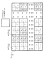
- FIG. 1 is an explanatory diagram of the ITU-T H.264 system that is an international video coding standard.
- a moving image is obtained by dividing an input frame 100 into a plurality of blocks and encoding in block units or a plurality of block units.
- FIG. 1 shows an example of block division in H.264.
- ITU-T H.264 which is an international video coding standard
- an image frame 100 is divided into macroblocks 103 each composed of 16 ⁇ 16 pixels.
- one of 4x4 and 8x8 is selected as orthogonal transform.
- the macro block 103 is further divided into 4 ⁇ 4 blocks (102) or 8 ⁇ 8 blocks (101), and encoding is performed using this block as an encoding unit.
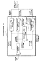
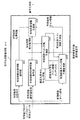
- FIG. 2 shows an image encoding apparatus that divides an image into a plurality of blocks and encodes the blocks.
- the coding block is 4x4 or 8x8.
- an encoded block predicted image that is a predicted image having high correlation with the encoded block is generated.
- ITU-T H.264 there are an inter prediction image generation unit, an intra prediction image generation unit, and the like.
- the inter prediction image generation unit selects a region similar to the encoded block from the decoded images decoded in the past, and outputs the selected region as an encoded block predicted image.
- the intra-predicted image generation unit generates an image similar to the encoded block from the local decoded image of the peripheral block that has already been encoded of the current encoded image by extrapolation prediction, and outputs the image as an encoded block predicted image.
- both the inter prediction image generation unit and the intra prediction image generation unit are collectively referred to as an encoded block prediction image generation unit 200.
- the side information encoding unit 209 uses the entropy code for side information such as motion vector information indicating the relative positions of the encoding target block and the decoded image block and the intra prediction mode used in the inter prediction image generating unit. And superimposed on the bitstream.
- entropy coding is a technique for optimally compressing data using the appearance frequency of data.
- the prediction error image generation unit 201 calculates a difference between the encoded block and the encoded block predicted image to generate a prediction error image. Then, the transform unit 202 transforms the prediction error image into frequency coefficients using frequency transform such as discrete cosine transform and Hadamard transform.
- the quantization unit 203 quantizes the frequency coefficient to generate a quantized coefficient.
- quantization is realized by dividing a frequency coefficient by an appropriate quantizer and converting it into an integer and outputting the value as a quantization coefficient.
- the quantizer is switched for each frequency component position of the coefficient in MPEG-2 which is another international video coding standard and H.264 described above.
- the quantization coefficient is inversely quantized to generate a reproduction frequency coefficient.
- inverse quantization is realized by a quantizer used in the quantization unit 203 multiplying the quantization coefficient.
- the inverse transform unit 205 applies a reverse frequency transform corresponding to the frequency transform used in the transform unit to the playback prediction error image, thereby generating a playback prediction error image.
- the local decoded image generation unit 206 adds the encoded block prediction image and the reproduction prediction error image to generate a local decoded image.
- This local decoded image is stored in the decoded image storage unit 208, used for generating an inter predicted image in the subsequent frames, and also used for generating an intra predicted image of an encoding target frame. Then, the quantized coefficient is entropy encoded by the quantized coefficient encoding unit 207, and encoded block entropy encoded data is generated for each encoded block.
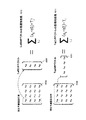
- FIG. 3 is an operation explanatory diagram of the conversion unit 202 of FIG.
- 301 shows the basis of Hadamard orthogonal transform. This conversion converts a four-point image into a four-point frequency.
- the values of the coefficients of the base pixels 0 to 3 having the frequency 0 are 0.5, 0.5, 0.5, and 0.5.
- the coefficient values of the base pixels 0 to 3 of frequency 1 are 0.5, 0.5, -0.5, and -0.5.
- the coefficient values of the pixels 0 to 3 are defined as 301.
- the frequency conversion of the prediction error image of 4x4 block can be realized by converting the vertical and horizontal directions by Hadamard orthogonal transform, for example.
- the frequency conversion in the vertical direction can be realized by expressing a 4 ⁇ 4 conversion target image in a matrix and multiplying this image by a Hadamard orthogonal transformation matrix from the left.
- the horizontal transformation can be realized by multiplying the result obtained by transposing a Hadamard orthogonal transformation matrix from the right.
- a frequency coefficient can be obtained for a prediction error image having a size of 4 ⁇ 4 blocks.
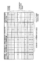
- FIG. 4 is an explanatory diagram of the processing operation of the encoding device shown in FIG. 2, and mainly shows changes in data values in the example of each pixel of the 4 ⁇ 4 block, taking the processing of 4 ⁇ 4 block conversion as an example.
- the Hadamard transform of FIG. 3 is used as the transform unit.
- the encoding target block 451 corresponds to one of the 16 blocks constituting the 4 ⁇ 4 block 102 in FIG. 1 and includes 16 pixels.
- the pixel value of the encoding target block prediction image block 450 with respect to the pixel value of the encoding target block (corresponding to the encoding block in FIG. 2) 451, for example, from the previous frame in time or from spatially adjacent images The difference between these pixel values is calculated by the prediction error image generation unit, and the pixel value of the prediction error image block 452 is generated.
- the pixel value is a value indicating the gradation of each pixel.
- the pixel value of the prediction error image block 452 of this 4 ⁇ 4 block is converted to a frequency by the Hadamard transform base of FIG. 3, and the value of the frequency coefficient block 453 is obtained.
- the frequency coefficient represents a horizontal frequency component in the horizontal direction, a vertical frequency component in the vertical direction, a low frequency of the horizontal / vertical component on the left and top, and a high frequency of the horizontal and vertical components on the right and bottom.
- the value of the frequency coefficient block 453 is quantized by the quantization unit.
- quantization is performed by dividing a frequency coefficient by a constant called a quantizer.
- the quantization method is calculated by the following equation, for example, where each coefficient is f, the quantizer is Q, and the quantization coefficient is C.
- sign (x) is a function that returns 1 if x is positive and -1 if negative.
- int (x) is a function that rounds off the decimal part of x to make it an integer
- abs (x) is a function that returns the absolute value of x.
- the quantizer is 3. Therefore, the value of the frequency coefficient block 453 of the DC component is ⁇ 7.25. And converted to a value of ⁇ 2 as a quantization coefficient. Other frequency coefficients are similarly quantized, and the value of the quantized coefficient block 454 is obtained.
- the quantized coefficient is converted into the value of the encoded block entropy encoded data block 458 by the quantized coefficient encoding unit.
- This quantization coefficient is further inversely quantized by the inverse quantization unit.
- the inverse quantization method is calculated, for example, by multiplying the inverse quantization coefficient by the inverse quantizer used in the quantization. That is, if the quantization coefficient is C, the quantizer is Q, and the reproduction frequency coefficient is f ′, It is represented by According to this equation, for example, the value of the DC component quantization coefficient block 454 is -2, so And converted to a value of -6 as a reproduction frequency coefficient. The other frequency coefficients are processed in the same manner, and the value of the reproduction frequency coefficient block 455 is obtained.
- the inverse conversion unit inversely transforms the reproduction frequency coefficient, and the pixel value of the reproduction prediction error image block 456 is generated.
- This reproduced prediction error image is added to the pixel value of the predicted image block 450 of the encoding target block by the local decoded image generation unit, and the pixel value of the local decoded image block 457 is generated.
- Each pixel value of the reproduction prediction error image block 456 is slightly different from each pixel value of the prediction error image block 452.
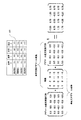
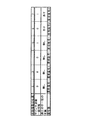
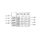
- FIG. 6 shows an example in which the value of the quantization coefficient block 454 of FIG. 4 is zigzag scanned and converted into non-zero effective coefficient information.
- Effective coefficient information which is a non-zero coefficient, is extracted, and position information in a zigzag scan, an absolute value of the effective coefficient, and sign information representing the sign of the effective coefficient are extracted from each effective coefficient.
- 0 is assigned as sign information when the quantization coefficient is positive, and 1 is assigned when it is negative.
- the first effective coefficient number in the zigzag scan order is 1
- the effective coefficient position information is 1
- the effective coefficient absolute value information is 2
- the effective coefficient sign information is 1.
- the effective coefficient of the second number has effective coefficient position information of 2, effective coefficient absolute value information of 3, and effective coefficient sign information of 0.
- the information in the table of FIG. 6 is obtained by sequentially converting in the same manner.
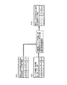
- FIG. 7 is a detailed configuration diagram of the quantized coefficient encoding unit 207 in FIG. 2 based on the above description.
- quantized coefficients are input to the quantized coefficient coding unit 207 in units of blocks.
- the quantized coefficient is decomposed by the effective coefficient information generation unit 720 into the effective coefficient position information, the effective coefficient absolute value information, and the effective coefficient sign information representing the positive / negative of the effective coefficient described with reference to FIG.
- an optimal entropy code is assigned by the effective coefficient position information encoding unit 721, and the effective coefficient position code is It is encoded efficiently.
- the effective coefficient absolute value information encoding unit 722 uses a bias that tends to generate a larger value as it is closer to the DC component and conversely tends to be smaller as it is closer to the high frequency.
- An optimal entropy code is assigned and is efficiently encoded as an effective coefficient absolute value code. For example, in the case of H.264 arithmetic coding (CABAC) mode, both the effective coefficient position information and the effective coefficient absolute value information reflect that a larger coefficient is more likely to appear at lower frequencies and a smaller coefficient at higher frequencies.
- CABAC H.264 arithmetic coding
- the optimal probability table is assigned to the arithmetic code in accordance with the position of the coefficient zigzag scan, thereby realizing highly efficient encoding.
- the effective coefficient sign information which is the sign of the coefficient
- positive and negative symbols are generated with the same probability of 0.5. Therefore, even if any entropy code is assigned, it cannot be efficiently encoded. For this reason, all the video coding standards such as ITU-T H.261 / H.263 / H.264, ISO / IEC MPEG-1, MPEG-2, MPEG-4 1-bit information is used and is output from the effective coefficient sign information encoding unit 723 as an effective coefficient sign code.
- the effective coefficient position code, the effective coefficient absolute value code, and the effective coefficient sign code are combined and output as encoded block entropy encoded data.
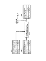
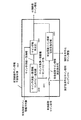
- FIG. 8 is a diagram showing the configuration of the image decoding apparatus corresponding to FIG.
- the quantized coefficient decoding unit 807 performs inverse entropy coding from the encoded block entropy coded data to decode the quantized coefficients, and then, similarly to the encoder, the inverse quantization unit 804 performs inverse quantization and inverse transform unit 805.
- a reverse prediction error image is generated by performing inverse transform in step (b).
- the encoded block predicted image generation unit 800 generates an encoded block predicted image
- the decoded image generation unit 806 adds the encoded block predicted image and the reproduction prediction error image to generate a decoded image. Then, this decoded image is stored in the decoded image storage unit 808 and simultaneously output for display.
- the local decoding unit of the encoding apparatus and a part of the decoding apparatus perform exactly the same operation. Therefore, the inverse quantization unit 804, the inverse transform unit 805, the encoded block predicted image generation unit 800, the decoded image generation unit 806, and the decoded image storage unit 808 in the decoding device in FIG.
- the same operations as those of the conversion unit 204, the inverse conversion unit 205, the encoded block predicted image generation unit 200, the decoded image generation unit 206, and the decoded image storage unit 208 are performed.
- sign information representing the sign of an effective quantization coefficient
- one bit is generally used for each coefficient. Since this sign information occupies 10% or more of the information amount of all target images, it is indispensable to reduce the sign information in order to further improve the compression rate.
- the pixel that is in contact with the boundary pixel of the block to be encoded and the pixel to be encoded are similar in the image included in the already decoded block.
- the sign information is efficiently encoded by generating a prediction value of the effective coefficient sign information and encoding whether or not the prediction value and the actual sign information coincide with each other.
- the presence of quantization coefficients means that there is a difference between the original image and the predicted image, that is, the accuracy of the predicted image is poor.
- pixels that are spatially in contact with each other have similar values. Therefore, it is expected that the boundary pixel in contact with the encoded block in the encoding target block has a value close to the pixel in contact with the encoding target block in the encoded block. Therefore, the value of the boundary pixel of the original image of the encoding target block can be estimated from the pixels in the encoding block that are in contact with the encoding target block.
- the difference between the original image and the predicted image at the boundary pixel of the encoded block can also be estimated from the pixel in contact with the encoding target block in the encoded block and the predicted image.
- an estimated value of the difference in the boundary pixel is set as a boundary pixel prediction error estimated value.
- the boundary pixel value in the reproduction prediction error obtained by dequantizing and inversely converting the quantization coefficient corresponding to the encoding target block is close to the boundary pixel prediction error estimated value.
- the absolute value and the position (frequency) of the quantized coefficients are known, the set of sign information of each coefficient for which the boundary pixel prediction error estimated value and the boundary pixel predicted error estimated value are close are obtained. It will be limited. Therefore, the sign information of each coefficient for which the boundary pixel of the reproduction prediction error and the estimated value of the boundary pixel prediction error are closest is a good prediction value of the actual sign information of each coefficient. If a good prediction value can be obtained, sign information can be efficiently encoded.
- each of the following embodiments first, from a locally decoded image of a coded block that has been coded before coding a coded block that contacts the coded block, and a coded block predicted image that is a predicted value of the coded block.
- the estimation value of the prediction error of the boundary pixel in contact with the encoded block among the encoded blocks is obtained.
- the sign that generates the reproduction prediction error that is closest to the estimated value of this prediction error is used as a sign information prediction value of an effective coefficient.
- Entropy encoding information on whether or not the sign information predicted value of the effective coefficient matches the sign information of the actual effective coefficient to be encoded (match information) is generated as ⁇ match '' or ⁇ not match '' information.
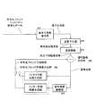
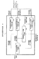
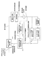
- FIG. 9 is a diagram illustrating an encoding apparatus based on the first embodiment.
- the first embodiment relates to a moving image encoding apparatus that divides an encoding target image into a plurality of block images and performs encoding for each encoding block.
- a quantized coefficient and a locally decoded image are generated from a prediction image and an encoding block that is an encoding target block. That is, first, the encoded block predicted image generation unit 900 generates an encoded block predicted image that is a predicted value of the encoded block by encoding. Next, a prediction error image generation unit 901 generates a prediction error image that is a difference between the encoded block and the encoded block prediction image. Subsequently, the conversion unit 902 converts the prediction error image into a frequency coefficient. Further, the quantization unit 903 quantizes the frequency coefficient to generate a quantization coefficient.
- the inverse quantization unit 904 inversely quantizes the quantization coefficient to generate a reproduction frequency coefficient.
- the inverse transformation unit 905 inversely transforms the reproduction frequency coefficient into a reproduction prediction error image.
- a local decoded image generation unit 906 generates a local decoded image from the reproduction prediction error image and the encoded block prediction image.
- boundary pixel predicted value generation unit 910 from the locally decoded images of a plurality of encoded blocks adjacent to the encoded block, the predicted value of the boundary pixel that contacts the encoded block in the encoded block A certain boundary pixel prediction value is generated.
- boundary pixel prediction error estimation unit 911 from the boundary pixel prediction value and the encoded block prediction image, the value of the boundary pixel and the boundary pixel prediction value of the encoded block prediction pixels with respect to the boundary pixel A boundary pixel prediction error estimated value is generated as the difference between the two.
- the quantized coefficient encoding unit 907 generates encoded block entropy encoded data by using the quantization coefficient and the boundary pixel prediction error estimated value (boundary pixel prediction error estimation information).
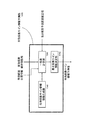
- FIG. 10 is a diagram illustrating a configuration of the quantized coefficient encoding unit 907 of FIG. 9 in the first embodiment.
- the effective coefficient information generating unit 1020 extracts a quantized coefficient whose value is not zero from the quantized coefficient as an effective coefficient, and effective coefficient position information indicating the frequency position of the effective coefficient.
- the effective coefficient absolute value information which is the absolute value of the effective coefficient, and the effective coefficient sign information representing the sign of the effective coefficient are generated. This operation is the same as that of the effective coefficient information generation unit 720 in FIG.
- the effective coefficient sign information prediction unit 1024 predicts sign information indicating whether the effective coefficient is positive or negative from the boundary pixel prediction error estimated value, the effective coefficient position information, and the effective coefficient absolute value information.
- An effective coefficient sign information prediction value that is a value is generated.
- the effective coefficients for generating the effective coefficient sign information prediction value may be all the effective coefficients of the coding block, or may be a part of the effective coefficients selected by a predetermined rule. .
- the configuration for generating the effective coefficient sign information prediction value for only some effective coefficients selected according to a predetermined rule will be described in detail in the fourth to sixth embodiments.
- the effective coefficient position information encoding unit 1021 generates the effective coefficient position code by entropy encoding the effective coefficient position information
- the effective coefficient absolute value encoding unit 1022 entropy encodes the effective coefficient absolute value information to Generate a value sign.
- the effective coefficient sign information prediction encoding unit 1023 entropy-encodes the sign prediction value match information indicating whether the effective coefficient sign information prediction value and the sign information of the effective coefficient match to generate an effective coefficient sign code. . Then, encoded block entropy encoded data is generated from the effective coefficient position code, the effective coefficient absolute value code, and the effective coefficient sign code.
- a highly accurate prediction value of effective coefficient sign information can be generated from effective coefficient position information, effective coefficient absolute value information, a predicted image, and a decoded image.
- the coincidence information as to whether or not the predicted value and the effective coefficient sign information coincide with each other will occupy a large number of “match” symbols.
- the information amount of the sign information is reduced. It is possible to reduce more.
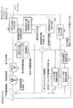
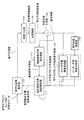
- FIG. 11 is a diagram showing a decoding device based on the second embodiment.
- the moving picture decoding apparatus according to the second embodiment divides an encoding target picture into a plurality of block pictures, and performs coding performed by the moving picture coding apparatus in FIG. 9 that performs coding for each coding block.
- the block entropy encoded data is decoded for each block.
- a decoded image is generated from encoded block entropy encoded data, as in the decoding apparatus of FIG. That is, the encoded block prediction image generation unit 1100 generates an encoded block prediction image that is a prediction value of the encoding block. Further, the quantization coefficient decoding unit 1107 decodes the quantization coefficient from the bit stream and the boundary pixel prediction error estimated value. Then, the quantization coefficient is inversely quantized by the inverse quantization unit 1104 to generate a reproduction frequency coefficient, and the inverse transformation unit 1105 inversely converts the reproduction frequency coefficient into a reproduction prediction error image, and the decoded image generation unit 1106 performs reproduction prediction. A decoded image is generated from the error image and the encoded block prediction image.
- the boundary pixel predicted value generation unit 1110 from the decoded images of a plurality of encoded blocks adjacent to the encoded block, the predicted value of the boundary pixel that contacts the encoded block in the encoded block A certain boundary pixel prediction value is generated.
- the boundary pixel prediction error estimation unit 1111 generates a boundary pixel prediction error estimation value for the boundary pixel from the boundary pixel prediction value and the encoded block prediction image, and sends it to the quantization coefficient decoding unit 1107.
- the quantization coefficient decoding unit 1007 generates a quantization coefficient from the encoded block entropy encoded data and the boundary pixel prediction error estimation value.
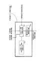
- FIG. 12 is a diagram illustrating a configuration of the quantization coefficient decoding unit 1007 of FIG. 11 in the second embodiment.
- the effective coefficient position information decoding unit 1231 extracts an effective coefficient position code from the encoded block entropy encoded data, and decodes effective coefficient position information that is the frequency position of the effective coefficient of the encoded block.
- the effective coefficient absolute value information decoding unit 1232 extracts the effective coefficient absolute value code from the encoded block entropy encoded data, and decodes the effective coefficient absolute value information that is the absolute value of the effective coefficient of the encoded block.
- the effective coefficient sign information prediction unit 1024 predicts sign information indicating whether the effective coefficient is positive or negative from the boundary pixel prediction error estimated value, the effective coefficient position information, and the effective coefficient absolute value information. An effective coefficient sign information prediction value that is a value is generated.
- the effective coefficient sign information prediction unit 1024 in FIG. 12 is exactly the same as the effective coefficient sign information prediction unit 1024 in FIG. 10 of the encoding device in the first embodiment.
- the effective coefficient sign effective coefficient Effective coefficient sign information which is sign information is decoded and output.
- the sign prediction value match information is “match”
- the sign information of the effective coefficient sign information prediction value is “same”
- the sign information indicates a sign opposite to the sign of the effective coefficient sign information prediction value. Is output.
- block quantization coefficients are generated from the effective coefficient absolute value information, effective coefficient position information, and effective coefficient sign information. Then, this quantized coefficient is processed by the same method as that of the decoding apparatus in FIG. 8 to generate a decoded image.
- the second embodiment it is possible to decode the encoded block entropy encoded data encoded in the first embodiment and further reducing the information amount of the sign information.
- FIG. 13 is a diagram illustrating an effective coefficient sign information prediction unit 1024 that is common to the first embodiment and the second embodiment.
- the effective coefficient sign information prediction value is obtained as follows. First, in the effective coefficient sign information candidate generation unit 1340, the effective coefficient sign information for each effective coefficient is positive or negative with respect to the coefficient given by the effective coefficient position information and the effective coefficient absolute value information in the coding block. A combination of a plurality of pieces of signature information to which these are temporarily assigned is generated. This is a valid coefficient sign information candidate. Since there are two types of sign information indicating the sign of each effective coefficient, positive and negative, for example, when generating effective coefficient sign information candidates for N effective coefficients, as a combination, a maximum of 2 to the Nth power There are street combinations.
- the degree of coincidence calculation unit 1341 calculates the degree of coincidence between each effective coefficient sign information candidate, the effective coefficient position information, and the reproduction prediction error signal obtained from the effective coefficient absolute value information and the boundary pixel prediction error estimated value. To do. Then, the maximum likelihood coefficient sign information determination unit 1342 outputs the effective coefficient sign information candidate having the highest degree of matching as the effective coefficient sign information prediction value. This effective coefficient sign information prediction value coincides with the effective coefficient sign information with a high probability. Therefore, by encoding the difference between the effective coefficient sign information and its predicted value, the probability of the symbol “matching” between them increases, and by performing optimal entropy encoding, information on the effective coefficient sign information The amount can be reduced.
- FIG. 14 is a diagram illustrating a third embodiment, which is another implementation of the effective coefficient sign information prediction unit 1024 (FIGS. 10 and 12) in the first and second embodiments.
- the effective coefficient sign information prediction value is obtained as follows. First, in the Gray code (gray code) effective coefficient sign information candidate generation unit 1440, effective coefficient sign information for each effective coefficient is obtained for the coefficient given by the effective coefficient position information and effective coefficient absolute value information in the coding block. A combination of a plurality of pieces of sign information tentatively assigned either positive or negative is generated so as to correspond to 0/1 of each bit position of the Gray code.
- the technique described in Patent Document 1 is referred to as a Gray code in accordance with a widely used name.
- the effective coefficients having different signs are identified between the immediately preceding effective coefficient sign information candidate and the effective coefficient sign information candidate to be evaluated. To do.
- the influence of the degree of coincidence on the cost calculation process is obtained from the change of the sign of the effective coefficient.
- the difference between the coincidence cost of the previous effective coefficient sign information candidate and the coincidence cost of the effective coefficient sign information candidate to be evaluated Ask for. Further, by adding this difference to the cost of the matching degree of the previous effective coefficient sign information candidate, the cost of matching degree of the effective coefficient sign information candidate to be evaluated is obtained.
- the maximum likelihood coefficient sign information determination unit 1442 outputs the effective coefficient sign information candidate having the highest degree of matching as an effective coefficient sign information prediction value. According to the third embodiment described above, without calculating the cost of matching every time, only the cost difference of the matching score is obtained from the effective coefficient sign information whose sign has changed, and this value is used as the matching score of the previous candidate. Therefore, the amount of calculation can be further reduced.
- the effective coefficient sign information prediction unit uses the prediction value of the sign information of the effective coefficient and encodes whether the prediction and the actual value match. Is generated.
- sign information of an effective coefficient with high prediction accuracy is generated, and as a result, the probability that the sign information matches the predicted value is increased.
- entropy codes can be encoded more efficiently when the probability of symbol occurrence is biased. By performing appropriate entropy coding, this coincidence information can be coded with an average of less than 1 bit per symbol. For this reason, it is possible to further reduce the amount of information of sign information by performing appropriate entropy coding on the sign information matching information.
- FIG. 15 is a diagram illustrating an encoding apparatus based on the fourth embodiment.
- the fourth embodiment shown in FIG. 15 is based on the first embodiment shown in FIG. 9, and is based on a quantization coefficient encoding unit 1507, a boundary pixel prediction error estimation unit 1511, and a boundary pixel prediction value generation unit 1510. Is disclosed in more detail.
- the processing units 1507, 1511, and 1510 correspond to the processing units 907, 911, and 910 having the same names in FIG. In FIG. 15, each processing unit having the same name as in FIG. 9 executes the same process as in FIG.
- a block having the values of the encoding target block 451 and the encoding target block prediction image 450 shown in FIG. 4 is converted into a conversion unit, a quantization unit, an inverse quantization unit, and an inverse conversion equivalent to those in FIG.
- An example of encoding using a local decoding unit and a local decoding generation unit is shown. Since these arithmetic processes are equivalent to a general method, the quantization coefficient shown in FIG. 15 is also the same as the quantization coefficient 454 of FIG.
- the local decoded image in FIG. 15 is also the same as the local decoded image 457 in FIG.
- details of the boundary pixel prediction value generation unit 1510, the boundary pixel prediction error estimation unit 1511, and the quantization coefficient encoding unit 1507 will be described in the fourth embodiment.
- FIG. 16 is a diagram illustrating an example of a boundary pixel of an encoding target block 1661 (encoding block) having a size of 4 ⁇ 4 when the base size of orthogonal transformation such as H.264 is 4 ⁇ 4.
- encoding processing proceeds in units of blocks from the upper left to the lower right. For this reason, encoding of the left and upper blocks of the encoding block is completed before encoding of the encoding block.
- a block that has already been encoded at the time of encoding the encoded block is referred to as a coded block (1662).
- the pixels on the upper and left ends of the encoded block are in contact with the encoded block. Therefore, the upper and left end pixels in the encoding target block in FIG. 16 are defined as boundary pixels (1660).
- FIG. 17 is a diagram illustrating a processing example of the boundary pixel predicted value generation unit 1510 according to the fourth embodiment.
- the boundary pixel prediction value generation unit 1510 receives a local decoded image in the vicinity of the left, upper left, and upper boundaries of the encoded block, and generates a boundary pixel prediction value.
- the pixels of the encoded block of the locally decoded image in contact with the boundary pixel are the same as those in FIG. 16.
- the pixels that touch the left are L0 to L3
- the pixels that touch the top are U0 to U3
- the pixels that touch the top left are UL, with respect to the pixels of the input local decoded image.
- the boundary pixel prediction values at the boundary pixels of the coding block are assumed to be E0, E1, E2, E3, E4, E5, and E6 in order from the lower left to the upper right.
- the boundary pixel predicted values E0 to E6 are obtained from the pixels L0 to L3, U0 to L3, and UL of the locally decoded image of the encoded block near the boundary pixel by the following formula.
- E0 L3
- E1 L2
- E2 L1
- E3 (L0 + UL + U0)
- E4 U1
- these boundary pixel prediction values are output.
- the value of the nearest pixel is used as it is or averaged.
- the neighborhood of the prediction target pixel is also used. It is also possible to use a pixel prediction method or the like in general pixel adaptive DPCM encoding using a plurality of pixels for generating a boundary pixel prediction value.
- FIG. 18 is a diagram illustrating an implementation example of the boundary pixel prediction error estimation unit 1511 in the fourth embodiment.
- a boundary pixel prediction error estimation value is generated from the boundary pixel prediction value generated in FIG. 17 and the value of the encoding target block prediction image 450 in FIG.
- the boundary pixel prediction values E0 to E6 are boundary pixel prediction values of the boundary pixels of the encoded block corresponding to FIG.
- Pixels P0 to P6 are values of boundary pixels of the encoded block prediction image.
- Pixels D0 to D6 are boundary pixel prediction error estimation values.
- n is a number between 0 and 6
- Dn En-Pn
- the boundary pixel prediction error estimated value of each pixel is obtained. For example, since the value of the pixel E3 is 57 and the value of the pixel P3 is 55, the value of 2 is obtained by subtracting 55 from 57.
- FIG. 19 is a diagram illustrating an implementation example of the quantized coefficient coding unit 1507 in the fourth embodiment.
- this implementation example not all effective coefficients but coefficients that use the effective coefficient sign information prediction value are selected, a coefficient that is predictively encoded using the sign information prediction value, and a general 1-bit fixed-length code are used. An example of combining with existing coefficients will be described.
- the effective coefficient information generation unit 1920 extracts, as an effective coefficient, a quantization value whose value is not zero from the quantization coefficient, and effective coefficient position information representing the frequency position of the effective coefficient, Effective coefficient absolute value information, which is the absolute value of the effective coefficient, and effective coefficient sign information representing the sign of the effective coefficient are generated.
- Effective coefficient absolute value information which is the absolute value of the effective coefficient
- effective coefficient sign information representing the sign of the effective coefficient
- an effective coefficient for predictively encoding sign information using an effective coefficient sign information prediction value, and a fixed length An effective coefficient for encoding sign information is determined using encoding, and an index of an effective coefficient for encoding sign information using the latter fixed-length encoding (fixed-length encoded sign information index) is output.
- an effective coefficient sign information predicted value that is a predicted value of sign information indicating whether each coefficient is positive or negative is generated.
- the effective coefficient position information encoding unit 1921 generates effective coefficient position code by entropy encoding the effective coefficient position information, and the effective coefficient absolute value encoding unit 1922 performs entropy encoding on the effective coefficient absolute value information to Generate a value sign.
- the effective coefficient sign information prediction encoding unit 1923 encodes the effective coefficient sign information.
- the effective coefficient sign information indicated by the fixed-length encoded sign information index is encoded using fixed-length encoding.
- the effective coefficient sign information is generated by entropy-encoding the sign prediction value matching information indicating whether the effective coefficient sign information prediction value and the sign information of the effective coefficient match.
- the encoded block entropy encoded data is generated by combining the effective coefficient position code, the effective coefficient absolute value code, and the effective coefficient sign code.
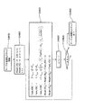
- FIG. 20 is a diagram illustrating an implementation example of the effective coefficient sign information prediction unit 1924 according to the fourth embodiment.
- the effective coefficient sign information candidate generation unit 2040 the effective coefficient sign information for each effective coefficient is positive or negative with respect to the coefficient given by the effective coefficient position information and the effective coefficient absolute value information in the coding block. Generate multiple combinations that are assigned. This is a valid coefficient sign information candidate. Since sign information indicating the sign of each effective coefficient is two types, positive and negative, for example, when generating effective coefficient sign information candidates for N effective coefficients, a maximum of 2 to the Nth power is combined. There are street combinations.
- the matching degree calculation unit 2041 includes an effective coefficient rearranging unit 2070, a quantized coefficient provisional value generation unit 2071, a boundary pixel prediction error provisional value generation unit 2722, and a prediction error matching degree calculation unit 2073.
- the effective coefficient rearrangement unit 2070 rearranges the effective coefficients using the effective coefficient position information and the effective coefficient absolute value information of the encoded block. This rearrangement is performed from an effective coefficient expected to have a high accuracy of the generated effective coefficient sign information prediction value to a lower effective coefficient. When the number of effective coefficients is large, a coefficient to be encoded using a prediction value by an effective coefficient sign information prediction value is selected from those having high accuracy as necessary.
- the provisional value of the quantization coefficient is applied to the effective coefficient reordered by the effective coefficient rearranging unit 2070 and applied to each effective coefficient sign information candidate code in the quantization coefficient provisional value generation unit 2071. Is generated for each effective coefficient sign information candidate.
- the boundary pixel prediction miscalculation provisional value generation unit 2072 dequantizes and inversely transforms the generated quantized coefficient provisional value to select only the boundary pixel, so that the boundary pixel that is the provisional error prediction value of the boundary pixel A prediction error provisional value is generated for each effective coefficient sign information candidate.
- the prediction error coincidence calculation unit 2073 calculates the degree of coincidence between the field pixel prediction error provisional value generated for each valid coefficient sign information candidate and the boundary pixel prediction error estimated value.
- the maximum likelihood coefficient sign information determination unit 2042 outputs the effective coefficient sign information candidate having the highest degree of coincidence generated by the prediction error coincidence calculation unit as an effective coefficient sign information prediction value. Since the difference between the effective coefficient sign information prediction value and the effective coefficient sign information generated from the quantization coefficient of the frequency coefficient of the prediction error image of the encoding target block of the original image is small, as shown in FIG. By encoding the difference by the effective coefficient sign information predictive encoding unit 1923, an effective coefficient sign code optimally entropy-coded can be obtained.
- FIG. 21 is a diagram illustrating a processing example of the effective coefficient rearranging unit 2070 in the fourth embodiment.
- the input to the effective coefficient rearranging unit 2070 is the same as the effective coefficient position information and effective coefficient absolute value information of the coding block in FIG.
- the provisional value of the boundary pixel prediction error is obtained by multiplying the base of the orthogonal transform corresponding to the effective coefficient by a value obtained by multiplying the inverse quantized value for all the effective coefficients of the coding block, and accumulating this. Is required. Therefore, the larger the effective coefficient absolute value, the greater the influence on the boundary pixel prediction error provisional value.
- a different quantizer is used for each effective coefficient position corresponding to the effective coefficient in H.264 or the like, so that the effective coefficient absolute value is inverted instead of the effective coefficient absolute value. It is also possible to determine the priority based on the quantized value.
- the effective coefficients are rearranged in the rearrangement process 2110 according to the above rules, and rearranged effective coefficient position information and effective coefficient absolute value information 2101 are obtained.
- the fourth embodiment in the selection process 2111, the first six coefficients are selected from the rearranged coefficients, and the coefficients are encoded using the effective coefficient sign information prediction value. decide. For the remaining two coefficients having the effective coefficient position information of 5 and 4, the effective coefficient position information of “5” and “4” is output as the fixed-length encoded sign information index 2103.
- These coefficients are encoded using a general method, for example, a fixed length code of 1 bit per code.
- the six effective coefficients 2102 are output as the coefficients that are rearranged and use the effective coefficient sign information prediction value.
- FIG. 22 is a diagram illustrating a processing example of the effective coefficient sign information candidate generation unit 2040 in the fourth embodiment.
- This figure shows an example of generating effective coefficient sign information candidates for the selected six effective coefficients.
- the effective coefficient is described on the figure using the position information of each effective coefficient as an index. Since there are six coefficients, there are 64 combinations of positive and negative sign information for the six coefficients, which is 2 to the sixth power. Therefore, first, an index of effective coefficient sign information candidates is prepared as 0 to 63, and a binary notation of this index is defined as a sign information candidate for each effective coefficient.
- the sign information candidate of each effective coefficient is defined as positive if the value is 0 and negative if it is 1.
- the effective coefficient sign information candidate index 2200 associated with the generated 64 effective coefficient sign information candidates 2201 is output to the quantized coefficient provisional value generation unit 2071.
- the index of the effective coefficient sign information candidate indicating the correct code is 8.
- FIG. 23 is a diagram illustrating a processing example of the quantization coefficient provisional value generation unit 2071 according to the fourth embodiment.
- the effective coefficient absolute value information corresponding to each effective coefficient position information is quantized by setting each code of effective coefficient sign information candidate 2201 of FIG. 22 corresponding to effective coefficient sign information candidate index 2200 as a coefficient.
- a process for generating a coefficient provisional value is described. For example, for the effective coefficient sign information candidate index 0, a positive coefficient is generated as a provisional value of quantized coefficients. Further, when the candidate index is 13, the coefficients of the effective coefficient position information 2, 3, and 9 are set as positive, and when the effective coefficient position information is 1, 10, and 7, the negative sign is set.
- FIG. 24 is a diagram illustrating a processing example of the boundary pixel prediction error provisional value generation unit 2072, the prediction error coincidence calculation unit 2073, and the maximum likelihood coefficient sign information determination unit 2042 in the fourth embodiment.
- the boundary pixel prediction error provisional value generation unit 2072 performs inverse quantization equivalent to that used in normal encoding for the quantization coefficient provisional values 2400a to 2400n generated for each effective coefficient sign information candidate. Apply reverse transformation.
- coefficients having original codes are set for coefficients that do not use the effective coefficient sign information prediction values of the effective coefficient position information 5 and 4 shown in FIG.
- boundary pixels are selected from the inversely converted values, and boundary pixel prediction error provisional values 2401a to 2401n are generated.
- the reason why the calculation is not equivalent but equivalent is that this calculation does not necessarily require high accuracy, and an operation with reduced calculation accuracy may be substituted to reduce the amount of calculation.
- the boundary pixel prediction error provisional values 2401a to 2401n, the boundary pixel prediction error estimated value generated by the boundary pixel prediction error estimation unit 1511, and Differences 2402a to 2402n are generated, and the cost values 2403a to 2403n obtained by squaring and adding these values squared are used as the degree of coincidence.
- the maximum likelihood coefficient sign information determination unit 2042 totals the degree of coincidence (square error cost) 2403a to 2403n for each effective coefficient sign information candidate and determines the effective coefficient corresponding to the effective coefficient sign information candidate index that gives the minimum cost.
- Coefficient sign information is output as an effective coefficient sign information prediction value. That is, the absolute value of the effective coefficient is reduced from the effective coefficient (nonzero element in the quantized coefficient block) of the frequency coefficient corresponding to the difference (prediction error) between the encoding target block and the encoded block prediction image.
- an effective coefficient sign information candidate whose effective coefficient sign information candidate index is 13 is output as an effective coefficient sign information prediction value.
- FIG. 25 is a diagram illustrating the effective coefficient sign information prediction encoding unit 1923 according to the fourth embodiment.
- the effective coefficient sign information that does not use the effective coefficient sign information prediction value that is, encodes sign information with a fixed length
- the switch 2501 based on the fixed-length encoded sign information index.
- the effective coefficient sign information is encoded by the effective coefficient sign information fixed length encoding unit 2503 with a fixed length using information of 1 bit per coefficient. For example, a 1-bit code of “0” is assigned to positive sign information and a “1” is assigned to negative sign information. In the case of the coefficients shown in FIG.
- the sign predicted value match information generation unit 2500 uses the effective coefficient sign information predicted value and the effective coefficient sign. Generates match information indicating whether the information matches.
- the effective coefficient sign information entropy coding unit 2502 entropy codes the matching information.
- FIG. 26 is a diagram for explaining the processing of the sign predicted value match information generation unit 2500 in the fourth embodiment.
- the upper part represents the position information of the effective coefficient
- the lower part represents the effective coefficient sign information, the effective coefficient sign information prediction value, and the sign prediction value match information corresponding to the effective coefficient position information.
- each effective coefficient it is determined for each effective coefficient whether the effective coefficient sign information 2601 of the six effective coefficients selected matches the effective coefficient sign information prediction value 2600.
- “1” is output as sign predicted value match information 2602. Since the effective coefficients are arranged in descending order of the expected prediction accuracy of the effective coefficient sign information prediction value 2600, the first order coefficient matches both, and the latter order coefficient decreases. For this reason, it is expected that the probability of “match” symbols is higher in the first half.
- “match” is 0 and “mismatch” is 1.
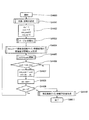
- FIG. 27 is a diagram illustrating an effective coefficient sign information entropy encoding unit 2502 according to the fourth embodiment.
- the order is rearranged in absolute value order, and the sign information predicted value match information is encoded in the rearranged order in comparison with the encoding of the sign predicted value match information 2602 of the selected coefficient. That is, in the fourth embodiment, as shown in the sine predicted value match information in FIG. 26, 0, 0, 0, which is the sine predicted value match information of the coefficient positions 2, 3, 1, 10, 8, and 7.
- Encoding is performed in the order of 1, 0, 1, and a sine prediction value match information entropy code 2700 is generated.
- an arithmetic code 1 (2701) and an arithmetic code 2 (2702) are prepared.
- the arithmetic code 1 is an optimal code when the probability (match probability) of the matching symbol “0” is 0.8 and the probability of the non-matching symbol “1” is 0.2
- the arithmetic code 2 is the matching symbol “0”. Is the optimal arithmetic coding method when the probability (match probability) is 0.6 and the probability of the mismatch symbol “1” is 0.4.
- the arithmetic unit 1 switches between the arithmetic code 1 and the arithmetic code 2 in a determination unit 2703 that determines whether or not there is a non-matching symbol before encoding the sign prediction value match information.
- arithmetic code a general arithmetic code described in Non-Patent Document 2 can be used.
- an arithmetic coding method in which the probability table is updated every time a symbol is coded such as CABAC used in the moving picture coding international standard ITU-T H.264.
- the first effective coefficient 2 is encoded in order with arithmetic code 1. As long as the previous sign prediction value match information is “match”, that is, “0”, encoding is performed with arithmetic code 1. When the sign prediction value match information of the effective coefficient immediately before becomes “mismatch”, that is, “1”, all sign prediction value match information after the next is encoded using the arithmetic code 2. In the case of FIG. 28, the arithmetic code 1 is used for the first effective coefficient (the position of the effective coefficient is 2).
- the encoder uses the arithmetic code 1. Since the sign prediction value match information with the effective coefficient position of 10 encoded as the position of the effective coefficient immediately before the code of 8 is “mismatch” “1”, the sign information with the effective coefficient positions of 8 and 9 is used. The predicted value match information is encoded with the arithmetic code 2.
- the sine prediction value match information is “mismatch”, that is, “matches” with “1” after the prediction coefficient whose prediction is off. ", That is, based on the fact that the probability of occurrence of" 0 "tends to be equal.
- step S2903 it is checked whether the variable State is 1 or not.
- the i-th sign predicted value match information S [i] is encoded with the arithmetic code 1 in step S2904.
- step S2905 it is determined whether S [i] is “match” or “not match”. Only in the case of “mismatch”, the state variable State is set to 2 in step S2907.
- step S2903 If it is determined in step S2903 that the State is not 1, that is, 2, the i-th sign predicted value match information S [i] is encoded with the arithmetic code 2 in step S2906.
- step S2903 it is determined whether the counter i is larger than n. If the counter i is larger, the encoding is terminated. Otherwise, the process proceeds to step S2903.
- FIG. 30 is a diagram for explaining an embodiment in which encoded block entropy encoded data 3000 is generated by combining effective coefficient position code 3001, effective coefficient absolute value code 3002, and effective coefficient sign code 3005.
- the effective coefficient sign information prediction unit 1924 in FIG. 19 generates a fixed-length encoding index from effective coefficient position information and effective coefficient absolute value information, and then generates fixed-length encoding sign information, An effective coefficient sign information predicted value is generated from the effective coefficient position information, the effective coefficient absolute value information, and the boundary pixel prediction error estimated value. For this reason, in order to generate the fixed-length coding index and the effective coefficient sign information prediction value on the decoding device side as well, there is a restriction on the code order.
- the effective coefficient position code 3001 and the effective coefficient absolute value code 3002 exist before the effective coefficient sign code 3005 so that the fixed-length coding index and the effective coefficient sign information prediction value can be generated on the decoding device side. It only has to be.
- the encoded block entropy encoded data according to the fourth embodiment includes effective coefficient position information 3001 having effective coefficient position information and effective coefficient absolute value information values as shown in FIG. 30, effective coefficients. It consists of an absolute value code 3002, sign information “1” and “0” of effective coefficient positions 5 and 4 encoded with a fixed length code 3003, and a sign prediction value match information entropy code 3005. Further, the sine prediction value match information entropy code 3005 includes match information “0”, “0”, “0”, “1” of the effective coefficient positions 2, 3, 1, and 10 encoded by the arithmetic code 1. It consists of coincidence information “0”, “1” of effective coefficient positions 8 and 7 encoded with arithmetic code 2.
- FIG. 31 is a diagram showing a decoding device based on the fifth embodiment.
- the fifth embodiment shown in FIG. 31 includes a quantization coefficient decoding unit 3107, a boundary pixel prediction error estimation unit 3111, and a boundary pixel prediction value generation unit 3110 based on the second embodiment shown in FIG. Further details will be disclosed.
- the processing units 3107, 3111, and 3110 correspond to the processing units 1107, 1111, and 1110 having the same names in FIG. In FIG. 31, each processing unit having the same name as in FIG. 11 executes the same processing as in FIG.
- the decoding apparatus of the fifth embodiment decodes the encoded block entropy encoded data 3000 of FIG. 30 generated by the encoding apparatus of the fourth embodiment of FIG. This is equivalent to the block described in the fourth embodiment.
- the inverse quantization unit, the inverse transform unit, the decoded image generation unit, and the encoded block predicted image generation unit are respectively the inverse quantization unit and the inverse transform unit described in the fourth embodiment of FIG.
- the local decoded image generation unit, the encoded block prediction image generation unit, the boundary pixel prediction value generation unit, and the boundary pixel prediction error estimation unit are the same. Therefore, the example of operation
- movement of each part is also equivalent to 4th Embodiment.
- the locally decoded image described in the fourth embodiment is replaced with a decoded image in the fifth embodiment. This is because each part described above is called a so-called local decoder, and is the same in the encoding device and the decoding device.
- the configurations and operation examples of the boundary pixel prediction value generation unit 3110 and the boundary pixel prediction error estimation unit 3111 are the same as those in the fourth embodiment.
- a general decoding device in FIG. 11 and a quantized coefficient decoding unit 3107 different from the fourth embodiment in FIG. 15 will be described.
- FIG. 32 is a diagram illustrating a quantized coefficient decoding unit 3107 according to the fifth embodiment.
- the operation will be described through a process of decoding the encoded block entropy encoded data 3000 of FIG. 30 according to the fourth embodiment.
- effective coefficient position information decoding section 3231 takes out effective coefficient position code 3001 from encoded block entropy encoded data 3000 and decodes effective coefficient position information that is the frequency position of the effective coefficient of the encoded block. As a result, from FIG. 30, as the effective coefficient position, 1, 2, 3, 4, 5, 7, 9, 10 Get. At the same time, the number of effective coefficients (8) is also acquired.
- effective coefficient absolute value information decoding section 3232 extracts effective coefficient absolute value code 3002 from encoded block entropy encoded data 3000 and decodes effective coefficient absolute value information that is the absolute value of the effective coefficient of the encoded block. .
- effective coefficient absolute value information 2,3,2,1,1,1,1,1 Get.
- the effective coefficient sign information prediction unit 1924 first generates a fixed-length encoded sign information index.
- an effective coefficient sign information prediction unit 1924 that is exactly the same as in the fourth embodiment is used. This is because it is necessary to generate exactly the same effective coefficient sign information prediction value in the encoding device and the decoding device. Therefore, description of the operation of the effective coefficient sign information prediction unit 1924 is omitted.
- the effective coefficient sign information prediction unit 1924 receives the effective coefficient position information and the effective coefficient absolute value information, and has 5, as the fixed-length encoded sign information index. 4 Is output.
- FIG. 33 is a diagram illustrating the effective coefficient sign information prediction decoding unit 3233 according to the fifth embodiment.
- the effective coefficient sign information fixed length code 3003 is selected by the switch 3301 according to the fixed length code sign information index, and is decoded by the effective coefficient sign information fixed length decoding unit 3303.
- the sign predicted value match information entropy code 3004 is selected by the switch 3301 according to the fixed-length code sign information index. Then, in the sign prediction value match information entropy decoding unit 3300, the sign prediction value match information entropy code 3004 is decoded, and as the sign prediction value match information, 0, 0, 0, 1, 0, 1 Get.
- the sign information reproduction unit 3302 compares the effective coefficient sign information predicted value with the coincidence information to generate valid coefficient sign information “0, 0, 0, 1, 0, 1”. As a result, the effective coefficient sign information 3703 corresponding to FIG. 6 is decoded.
- the effective coefficient sign information prediction value 3701 “0, 0.1, 1, 0, 1” is generated by the effective coefficient sign information prediction unit 1924 shown in FIG.
- the effective coefficient sine information prediction unit 1924 obtains the first value from the fixed-length encoded sine information obtained by the effective coefficient sine information fixed-length decoding unit 3303 and the boundary pixel prediction error estimation value generated by the boundary pixel prediction error estimation unit 3111.
- the effective coefficient sign information prediction value is generated by the same method as described with reference to FIGS.
- the boundary pixel prediction error estimation value input to the effective coefficient sign information prediction unit is the same method as that described in the fourth embodiment with reference to FIGS. 16 to 18 in the boundary pixel prediction error estimation unit 3111. Is generated.
- FIG. 34 is a diagram showing a sine prediction value match information entropy decoding unit 3300 in the fifth embodiment, and corresponds to the sine prediction value match information entropy encoding unit 3502 in the fourth embodiment of FIG. .
- the sine prediction value match information entropy encoding unit includes arithmetic decoding 1 (3401) and arithmetic decoding 2 (3402) corresponding to arithmetic code 1 (2701) and arithmetic code 2 (2072), respectively.
- Arithmetic decoding 1 is designed to be most efficient when the probability of a “match” symbol is 0.8
- arithmetic decoding 2 is designed to be most efficient when the probability of a “match” symbol is 0.6. is there.
- the selection method of arithmetic decoding 1 and arithmetic decoding 2 is the same as that of the sign prediction value match information entropy encoding unit 2502 in the fourth embodiment. This operation will be described with reference to FIG.
- the first effective coefficient position is decoded in order from the arithmetic coefficient 1 to obtain sign prediction value match information.
- the sign prediction value match information decoded immediately before is “match”, that is, “0”
- decoding is performed by arithmetic decoding 1.
- the sign prediction value match information of the effective coefficient decoded immediately before becomes “mismatch”, that is, “1”, all the sign prediction value match information entropy codes after that use arithmetic decoding 2.
- arithmetic decoding 1 is used for the first sign predicted value match information entropy code (effective coefficient position is 2). Further, since the sign prediction value match information of the effective coefficient decoded immediately before is “match” “0” until the positions of the effective coefficients are 3, 1, and 10, the decoder uses arithmetic decoding 1. Since the sign prediction value match information with an effective coefficient position of 10 decoded immediately before the sign prediction value match information entropy code with an effective coefficient position of 8 is “mismatch” “1”, the position of the effective coefficient is 8 And 9 sign prediction value match information entropy codes are encoded by arithmetic decoding 2.
- FIG. 36 is a flowchart for describing arithmetic decoding selection processing used for decoding of sign prediction value match information.
- step S3601 n sign predicted value match information entropy codes are input.
- n storage areas S [i] for sign prediction value match information are prepared.
- the counter i is initialized to 1.
- step S3603 check if the variable State is 1. In the case of 1, the i-th sign predicted value match information entropy code is decoded by arithmetic decoding 1 in step S3604, and the obtained sign predicted value match information is stored in S [i]. In step S3605, it is determined whether the decrypted S [i] is “match” or “mismatch”. Only in the case of “mismatch”, the state variable State is set to 2 in step S3607.
- step S3603 If it is determined in step S3603 that the State is not 1, that is, 2 in step S3606, the i-th sign predicted value match information entropy code is decoded by arithmetic decoding 2 in step S3606, and the obtained sign predicted value match information is obtained. Store in S [i].
- Step S3609 it is determined whether or not the counter i is greater than n. If the counter i is larger, the decoding process is terminated. Otherwise, the process proceeds to step S3603.
- FIG. 37 is a diagram for explaining the processing of the sign information reproduction unit 3302 in the fifth embodiment.
- the upper part represents the position information of the effective coefficient
- the lower part represents the effective coefficient sign information, the effective coefficient sign information prediction value, and the sign prediction value match information corresponding to the effective coefficient position information.
- the sine prediction value match information 3702 has a value of 0 when the effective coefficient sine information prediction value and the sine information match, and 1 when they do not match. Therefore, the sign information reproduction unit 3302 calculates the effective coefficient sign information predicted value 3701 and the sign predicted value match information 3702 for each sign information of each coefficient by exclusive OR calculation, thereby obtaining sign information 3703 for each effective coefficient. Is played.
- the effective coefficient sign information predictive decoding unit 3333 in FIG. 32 collects the effective coefficient sign information generated by the effective coefficient sign information fixed length decoding unit 3303 and the sign information reproduction unit 3302 to obtain the effective coefficient sign of the coding block. Output as information.
- the quantization coefficient is input to the inverse quantization unit in FIG. 31, and the image is decoded by a method similar to a general decoding device.
- the encoded block entropy data encoded efficiently in the fourth embodiment can be correctly decoded.
- the sixth embodiment is another embodiment of the effective coefficient sign information prediction unit 1924 (FIGS. 19 and 32) common to the fourth and fifth embodiments.
- the four-point Hadamard transform is one of the most basic orthogonal transforms.
- FIG. 38 is a diagram for explaining orthogonal basis vectors constituting the 4-point Hadamard transform according to the sixth embodiment.
- a frequency 0 basis vector is defined as T 0 (3800)
- a frequency 1 basis vector is defined as T 1 (3801)
- a frequency 2 basis vector is defined as T 2 (3802)
- a frequency 3 basis vector is defined as T 3 (3803).
- This four-point Hadamard transform can be expressed using the orthogonal basis vectors that are the four horizontal vectors.
- the coefficient corresponding to pixel 0 in the base vector T 0 (3800) at frequency 0 is t0 0 (3850), and the base vector T 1 (3801) at frequency 1 is The coefficient corresponding to pixel 0 is t0 1 (3851), the coefficient corresponding to pixel 0 is t0 2 (3852) in the frequency 2 basis vector T 2 (3802), and the frequency 3 basis vector T 3 (3803)
- the coefficient corresponding to pixel 0 is defined as t0 3 (3853).
- FIG. 39 shows the relationship between the reproduction frequency coefficient matrix 3955 and the reproduction prediction error matrix 3956 in the two-dimensional four-point Hadamard transform performed by the inverse transformation unit 905 in FIG.
- a weighted cumulative sum expression 3920 by each frequency coefficient 3911 of the reproduction frequency coefficient matrix 3955 of the dimensional orthogonal base 3922 will be described.
- the reproduction prediction error matrix 3956 that is the output of the inverse transform unit 905 in FIG. 9 generally includes a Hadamard orthogonal transformation matrix 3910 from the right and a Hadamard orthogonal transformation matrix 3911 from the left with respect to the reproduction frequency coefficient matrix 3955. It is calculated by multiplying.
- the Hadamard orthogonal transformation matrix 3910 is derived from the bases T 0 (3800), T 1 (3801), T 2 (3802), and T 3 (3803) of the frequencies 0 to 3 of the Hadamard transform described in FIG. Composed.
- the transposed matrix 3911 of the Hadamard transform has T 0 t (3900), T 1 t (3901), T 2 t (3902), T 2 t (3902), transposed bases of the frequency 0 to the frequency 3 of the Hadamard transform described in FIG. It consists of each vertical vector of T 3 t (3903).
- the reproduction prediction error matrix 3956 is expressed as a cumulative sum representation of the 4-point Hadamard transform from the Hadamard transform bases T 0 to T 4 and their transposed vectors T 0 t to T 4 t and the coefficients of the reproduction frequency coefficients. It can be expressed as Here, the cumulative sum representation 3920 of the four-point Hadamard transform has a reproduction frequency coefficient X ij (3921) having a horizontal frequency i and a vertical frequency j with respect to a 4 ⁇ 4 two-dimensional orthogonal base 3922 having a horizontal frequency i and a vertical frequency j. The product is the cumulative addition at all horizontal / vertical frequencies.
- FIG. 40 is a diagram for explaining the relationship between the upper 4 pixels / left end 4 pixels of the reproduction prediction error matrix 4056 and the reproduction frequency coefficient.
- the left four boundaries of the reproduction prediction error matrix are defined as LeftDiff vector 4000, and the four upper boundary pixels of the reproduction prediction error matrix are defined as TopDiff vector 4001.
- the LeftDiff vector 4000 can be represented as a left-difference four-pixel cumulative sum representation 3920 in FIG.
- the TopDiff vector 4001 can be expressed as a cumulative sum representation 4011 of the TopDiff vector by extracting the top four pixels of the cumulative sum representation 3920 of the 4-point Hadamard transform in FIG.
- FIG. 41 is a diagram for explaining the definition of the vector representation of the upper / left boundary pixels of the boundary pixel prediction error estimation value created by the boundary pixel prediction error estimation unit 1511 and the like of FIG. 18 in the fourth embodiment.
- the leftmost four pixels of the boundary pixel prediction error estimated value 4100 are defined as a LeftEst vector 4100.
- the top four pixels of the boundary pixel prediction error estimated value 4100 are defined as a TopEst vector 4101.
- FIG. 42 is a diagram illustrating an effective coefficient sign information prediction unit according to the sixth embodiment.
- This configuration is a more specific example of the configuration of the third embodiment described with reference to FIG.
- the Gray code order effective coefficient sign information candidate generation unit 4240 is a specific embodiment of 1440 in FIG.
- the Gray code order coincidence calculation unit 4141 including the effective coefficient rearranging unit 4270, the initialization unit 4271, and the Gray code order prediction error coincidence update unit 4272 has a configuration in which 1441 in FIG. 4 is embodied.
- the maximum likelihood coefficient sign information determination unit 4242 is the same as 1442 in FIG.
- the effective coefficient rearranging unit 4270 effective coefficient position information and effective coefficient absolute value information to be encoded using the sign information prediction value from the effective coefficient position information and effective coefficient absolute value information, and fixed length encoding Generate a signature information index.
- the process may be equivalent to that of the effective coefficient rearranging unit of the fourth embodiment described with reference to FIGS.
- initialize from the effective coefficient to be encoded using the sign information prediction value and the coefficient information encoded using the fixed-length code, several initial values used for the calculation by a method described later are obtained. initialize.
- Gray code order effective coefficient sign information candidate generation unit 4240 an index of sign information candidates is generated in the order of Gray codes.
- the code disclosed in Patent Document 1 is referred to as a Gray code (Gray code) that is widely used.
- the Gray code order prediction error coincidence update unit 4272 calculates the prediction error coincidence in Gray code order.
- the sign information candidate evaluated in this order differs from the sign information candidate evaluated immediately before by at most one sign of the effective coefficient. It will not be. Therefore, as will be described later, the cost difference before and after the sign change of the effective coefficient whose sign is different from that of the previous evaluation is simply added to the cost of the degree of coincidence of the previously evaluated sign information candidates, and the sign to be evaluated next Since the cost of the degree of coincidence of information candidates can be obtained, the degree of coincidence calculation is significantly reduced.
- the maximum likelihood coefficient sign information determination unit 4242 outputs the most likely effective coefficient sign information candidate as an effective coefficient sign information prediction value. This operation may be a process equivalent to the maximum likelihood coefficient information determination unit 2042 described in FIG.
- the number of effective coefficients encoded using the sign information prediction value in the effective coefficient rearranging unit 2070 is n.
- the effective coefficient encoded using the sign information prediction value is referred to as “inspection coefficient”. It is defined as
- the kth effective coefficient whose horizontal and vertical frequencies are (i k , j k ) is defined by the following equation (6).
- the sign of the sign information candidate generated by the Gray code order effective coefficient sign information candidate generation unit 4240 for the kth effective coefficient whose horizontal and vertical frequencies are (i k , j k ) Is defined by the following equation (7).
- Equation 7 used in the description of the sixth embodiment is different from the sign information definition (positive: 0 / negative: 1) of the fourth and fifth embodiments. .
- the quantization coefficient has a value of the following equation (8).
- the quantized coefficient provisional values indicated by reference numerals 2400a to 2400n in FIG. 24 are expressed by the following Equation 10 where each coefficient of the quantized coefficient provisional values of the horizontal frequency i and the vertical frequency j is zij. Can be expressed.
- the reproduction prediction error provisional value is obtained by inverse quantization and inverse conversion of the quantization coefficient provisional value. This value is obtained by substituting the provisional quantization coefficient for the reproduction frequency coefficient and performing inverse transformation.
- the LeftDiff vector 4000 which is the leftmost boundary four pixels of the reproduction prediction error
- the TopDiff vector 4001 which is the upper boundary four pixels of the reproduction prediction error
- T x and t0 x are defined as follows.
- the cost can be expressed as a cumulative sum of square values of differences between the boundary pixel prediction error estimated value and the reproduction prediction error provisional value. Therefore, the degree of coincidence with the provisional value of the quantized coefficient having (s i0 j0 , s i1 j1 , s i2 j2 ,..., S in-1 jn-1 ) as sign information (boundary pixel prediction error estimated value and reproduction)
- the cumulative sum of square values of differences from the prediction error provisional value can be defined as the absolute value square value of the difference vector of both vectors representing the reproduction prediction error estimation value and the reproduction prediction error provisional value by the following equation (16).
- TopEst and LeftEst are defined as follows, as described in FIG.
- Equation 16 is transformed using the set definition of Equation 19 to Equation 22 so that the coefficients to be multiplied to orthogonal basis vectors T i and T j are combined into one, and then the absolute value square calculation of the vector is expanded. By doing so, it can be transformed as shown in the following Expression 23.
- ⁇ A, B> is an inner product of the vectors A and B.
- T x forms an orthonormal basis, the following equation (24) is used for expansion from equation (16) to equation (23).
- FIG. 43 shows an example of effective coefficient sign information candidates based on the Gray code when four coefficients are set as the inspection target coefficients.
- the effective coefficient sign information candidate index it is defined so that the k-th value of the Gray code expression becomes the effective coefficient sign information candidate of the kth effective coefficient.
- the hatched portion in this figure is a code different from the immediately preceding effective coefficient sign information candidate. As shown in the figure, it can be seen that only one effective coefficient sign always changes between consecutive effective coefficient sign information candidates.
- the sign information of the idx-th effective coefficient sign information candidate is (s i0j0 , s i1j1 , s i2j2 , ..., s imjm , ..., s in-1 jn-1 ), (idx + 1
- the sign information of the) th effective coefficient sign information candidate can be expressed as (s i0j0 , s i1j1 , s i2j2 , ..., -s imjm , ..., s in-1 jn-1 ). Therefore, the difference between the cost of the coincidence of the sign information candidate (idx + 1) and the cost of the coincidence of the idx-th sign information candidate is obtained by substituting the respective sign information into Expression 23 and taking the difference.
- the following equation 25 can be used.
- Equation 26 it can be seen that the difference between them has only information related to the horizontal frequency component i m and the vertical frequency component j m of the coefficient in which the sine information is inverted. Therefore, the calculation of the difference in the cost of matching between the idx-th and (idx + 1) -th effective coefficient sign information candidates according to Equation 26 is more computationally intensive than when all the costs of matching according to Equation 23 are obtained. Significantly less.
- the cost of the (idx + 1) -th matching degree can be obtained by simply adding the value obtained by Expression 26 to the idx-th matching degree cost.
- the method of adding the value of Expression 26 to the cost of the idxth matching score is much smaller than the method of calculating the matching cost every time based on Expression 23, with the (idx + 1) th calculation cost being significantly smaller. The cost of coincidence can be obtained.
- Equation 26 the (A m ) term, the (B m ) term, and the (C m ) term are constants related to the m-th inspection target coefficient. Therefore, by associating the values of the terms (A m ), (B m ), and (C m ) related to all the inspection target coefficients with the number m of the inspection target coefficient in advance, The difference calculation of the coincidence cost can be obtained with a smaller amount of calculation.
- the (X) term and (Y) section respectively, from the equation 23, if the effective coefficient sign information candidate index is idx, weighting coefficients of the orthogonal basis vectors T im the horizontal frequency i m , And the weighting coefficient of the orthogonal basis vector T jm whose vertical frequency is j m . Therefore, the (X) term and (Y) term need to be updated to the weighting coefficient of (idx + 1) as the effective coefficient sign information candidate after calculating the cost of the degree of coincidence of (idx + 1). .
- the next effective coefficient sign information candidate indexes to be obtained is defined as (idx + 1) values similarly Weight_H of (X) of the horizontal information frequency i m if (idx + 1) [i m ]. Then, as shown in Equation 27, Weight_H (idx + 1) [i m ] is the value (X) of Weight_H (idx) [i m ] and the coefficient to be inspected when the effective coefficient sign information candidate index is idx. From the constant (A m ) associated with the number m, the following equation 28 is used.
- Weight_H (idx + 1) [i m ] is equal to Weight_H (idx) [i m ] and sign information S imjm (positive: 1 / negative) of coefficient m of the idx-th sign information candidate index is (A m ). : Subtract the product multiplied by -1).
- Equation 29 the value (Y) of the horizontal information frequency j m when the effective coefficient sign information candidate index is idx is defined as Weight_V (idx) [i m ] as shown in Equation 29.
- Weight_V (idx + 1) [j m ] is sine information s imjm (positive: 1 / negative ) with respect to Weight_V (idx) [j m ], and (B m ) is the coefficient m of the idx-th sign information candidate index. : Subtract the product multiplied by -1).
- the values of the (idx + 1) th (X) term and (Y) term of the sign information candidate index are (x) of the sign information candidate index idxth, respectively. Since the values of the constants (A m ) and (B m ) need only be added to and subtracted from the values of the term and (Y) term according to the sine information s imjm , the (X) term and (Y ) Term can be calculated.
- Equation 26, Equation 28, and Equation 30 can be calculated by a recurrence equation in which the cost calculation of each sign information candidate index is added to the cost calculation value of the immediately preceding sign information candidate index. Is shown.
- cost calculation based on inverse quantization and inverse frequency transform processing is executed only for the first sign information candidate index, and a recurrence formula is used for cost calculation for the second and subsequent sign information candidate indexes. Only calculations are performed. Thereby, the cost calculation for all the sign information candidate indexes can be completed.
- FIG. 44 is a flowchart of the derivation process of the effective coefficient sign information prediction value in the sixth embodiment.
- step S4401 variables and constants necessary for calculation are set.
- FIG. 45 is a diagram for explaining the detailed operation of step S4401.
- Step S4501 is a step of defining each variable / constant.
- L is the order of the orthogonal basis. Although it is 4 in the sixth embodiment, it is not limited to 4. Also, the order of orthogonal bases which are different in the horizontal and vertical directions may be used.
- Q is the value of the quantizer.
- t0x is a coefficient of the pixel 0 of the orthogonal basis of the frequency x.
- n is the number of inspection target coefficients.
- (i k , j k ) is the horizontal / vertical frequency of the k-th inspection target coefficient to be inspected, and k takes a value from 1 to n.
- C ikjk is the absolute value of the quantized value of the k-th inspection target coefficient among the n inspection target coefficients.
- Weight_H [0 ... L-1] is the (X) term of Equation 26 for each horizontal frequency
- Weight_V [0 ... L-1] is the (Y) term of Equation 26 for each vertical frequency. Is to hold the value of.
- Table_H [1 ... n], Table_V [1 ... n], and Table_HV [1 ... n] are expressed by Equation 26 where m is the number of the coefficient to be inspected (k is 1 to n). This is a table for recording (A k ), (B k ), and (C k ) terms.
- M is a variable for storing the position of the inspection target coefficient having different sign information in the immediately preceding effective coefficient sign information candidate index (idx) and the next effective coefficient sign information candidate index (idx + 1).
- Idx is a variable for holding an index of effective coefficient sign information candidates to be checked.
- min_idx is a variable for holding an index of effective coefficient sign information candidates that gives the cost of the minimum matching degree in the process of evaluating in order.
- cost is a variable for holding the cost of coincidence in the index of the effective coefficient sign information candidate to be inspected.
- Min_cost is a variable for holding the cost of the minimum matching degree corresponding to min_idx during the evaluation in order.
- PredSign [1 ... n] is an effective coefficient sign information prediction value output from the effective coefficient sign information prediction unit 4224 in FIG.
- the effective coefficient sign information candidate index idx is set to 1.
- the cost of matching is set to 0. This cost corresponds to idx being 0, that is, all the pieces of sign information of n inspection target coefficients are positive.
- the cost of coincidence can all be updated based on the difference, that is, the relative value, and that it is sufficient to obtain idx that gives the minimum value of the cost. Even if the initial value of cost is set to 0, it does not affect the derivation of idx that gives the minimum cost.
- step S4403 in FIG. 44 table initialization is performed.
- FIG. 46 is a diagram for explaining the table initialization step S4403 in the sixth embodiment. This step S4403 corresponds to the processing of the initialization unit 4271 in FIG.
- step S4601 tables Weight_H [0 ... L-1] and Weight_V [0 ... L-1] are initialized to zero. Also, the counter variable k is initialized to 1.
- step S4602 Table_H [1 ... n], Table_V [1 ... n], and Table_HV [1 ... n] are initialized.
- Table_H [k], Table_V [k], and Table_HV [k] are the values of (A k ), (B k ), and (C k ) of Equation 26, ie, Equation 31 The values are set according to Equation 32 and Equation 33.
- Equation 31 the values set in each table in Equation 31, Equation 32, and Equation 33 are approximations obtained by rounding each equation to an appropriate bit width in order to reduce the bit width necessary to store the value. A value may be used.
- Weithg_H [0 ... L-1] and Weight_V [0 ... L-1] are the respective coefficients according to the definitions of the (X) and (Y) terms in Equation 23 or Equation 26.
- the contribution of the weight to the orthogonal basis vector of each frequency is added.
- idx 0, that is, since the signs of all the inspection target coefficients are positive, the sign information is positive for the horizontal frequency i k and the vertical frequency j k of the inspection target coefficient at the k th inspection target frequency.
- the case contributions may be cumulatively added to Weithg_H [i k ] and Weight_V [j k ], respectively.
- step S4603 the counter k is incremented. If k is larger than n in step S4604, the process is completed. If not, the process of step S4602 is performed for the inspection target coefficient that has not been set.
- step S4404 in FIG. 44 the coefficient m for which the sign information of the effective coefficient sign information candidate changes between the index idx of the Gray code order effective coefficient sign information candidate and the previous index (idx-1). And the sign change information s is generated.
- This step S4404 corresponds to the processing of the Gray code order effective coefficient sign information candidate generation unit 4240 in FIG.
- FIG. 47 is a diagram for explaining the processing in step S4404 in the sixth embodiment.
- each variable is set.
- the previous effective coefficient sign information candidate index prev_idx is obtained by subtracting 1 from the current idx.
- a binary representation CandGrayCode of the Gray code of the current effective coefficient sign information candidate is obtained.
- the exclusive OR is “ ⁇ ” and the n-bit right shift of x is “x >> n”
- the CandGrayCode can be obtained by the following Expression 36.
- prev_idx is set as PrevCandGrayCode, and is similarly obtained by the following equation (37).
- step S4707 this step is terminated.
- this step S4404 can also be realized as a table of m and s having values corresponding to the effective coefficient 4300 having a change and the code change 4301 in the figure using the effective coefficient sign information candidate index as a key in accordance with FIG. 43 and the like. It is.
- step S4405 is a step for obtaining the cost of the degree of coincidence of the value of the effective coefficient sign information candidate index idx. This step corresponds to the processing of the Gray code order prediction error coincidence update unit 4272 of FIG.
- FIG. 48 illustrates a flowchart for updating the cost of matching in step S4405.
- the sign information candidate s imjm of the previous m-th coefficient is 1 (positive) in Equation 26, and Table_H [m] is used as terms (A m ), (B m ), and (C m ), respectively.
- Table_V [m] and Table_HV [m] Weight_H [i m ] as the term (X), and Weight_V [j m ] as the term (Y) are substituted.
- i m and j m is a horizontal frequency and vertical frequency of the m-th inspected coefficients.
- step S4803 first, the cost of coincidence is calculated. This update is performed as shown in Equation 41.
- the sign information candidate s imjm of the previous m-th coefficient in Equation 26 is ⁇ 1 (negative), and the terms (A m ), (B m ), and (C m ) are expressed as Table_H [m ], Table_V [m], Table_HV [m], Weight_H [i m ] as the term (X), and Weight_V [j m ] as the term (Y). Also, i m and j m is a horizontal frequency and vertical frequency of the m-th inspected coefficients.
- the update calculation of the cost of coincidence in this step S4802 or S4803 realized 7 operations, 2 multiplications, 2 arithmetic shifts (the operation to double Weight_H [i m ] and Weight_V [j m ] by arithmetic shift) The amount of calculation is very small.
- step S4406 in FIG. 44 it is determined whether or not the cost obtained in step S4405 is smaller than min_cost. By substituting, the signature information candidate index that gives the cost of the minimum matching degree is updated.
- step S4408 the effective coefficient sign information candidate index idx is incremented, and in step S4409, this value is compared with 2 to the nth power to determine whether all the effective coefficient sign information candidate indexes have been evaluated.
- the effective coefficient sign information predicted value is generated in step S4410.
- FIG. 49 is a flowchart for describing a method for generating an effective coefficient sign information prediction value in step S4410.
- step S4901 the corresponding Gray code is obtained from the effective coefficient sign information candidate index min_idx that gives the cost of the minimum degree of matching, and is set to the variable MinGrayCode.
- step S4902 the counter k is initialized to 1. This k corresponds to the number of the inspection object coefficient.
- step S4903 it is determined whether or not the value of the k-th bit of MinGrayCode is 0. In this case, 1 is set in step S4905.
- step S4906 the counter is incremented.
- step S4907 it is determined whether the effective coefficient sign information prediction values of all the inspection target coefficients have been obtained. And when the effective coefficient sign information prediction value of all the inspection object coefficients is set, this step is ended.
- processing of the maximum likelihood coefficient sign information determination unit 4242 in FIG. 42 corresponds to each step of S4406, S4407, S4408, S4409, and S4410 in FIG.
- the influence of the fixed-length code on the reproduction prediction error may be calculated in advance, and the reproduction prediction error estimated value may be corrected in advance based on the contribution.
- An example of the correction method will be described below.
- a set of horizontal and vertical frequencies of coefficients using a fixed-length code is defined as Equation 44 in terms of SHV_Fix .
- the cumulative sum expression 4010 of the LeftDiff vector is expressed by the following Expression 45.
- the cumulative sum representation 4010 of the TopDiff vector is expressed by the following equation (46).
- a vector TopEst ′ and a vector LeftEst ′ are defined as in Expression 48.
- the effective coefficient sign information prediction value can be obtained by the same method as when there is no coefficient using a fixed-length code. .
- the terms (Am), (Bm), and (Cm) described in Expression 26 of the sixth embodiment are expressed by Expression 26 when the sign information of the corresponding coefficient changes when these values are large. It is expected that the change in the value of is large, that is, the influence of the degree of coincidence on the cost is great.
- a larger reduction in the amount of information can be expected by rearranging the coefficients with priority given to the coefficient that greatly changes the degree of coincidence. Therefore, in the effective coefficient rearranging unit 4270 (FIG. 42) in the sixth embodiment, the values of the terms (Am), (Bm), and (Cm) are obtained in advance for all the coefficients, and all of their absolute values are calculated.
- An embodiment is also possible in which the higher the coefficient obtained by weighting and adding a part or some, the higher the coefficient, the rearrangement is.
- the method for realizing the effective coefficient sign information prediction unit according to the sixth embodiment described above can be applied to both the encoding device and the decoding device according to the fourth and fifth embodiments.
- the 4-point Hadamard transform has been described as an example, but the 6-point orthogonal transform and other orthogonal transforms used in ITU-T H.264 are not lost in generality.
- the method described in the embodiment can be applied.
- each formula, for example, Formula 31, Formula 32, Formula 33, etc. does not depend on a specific order of orthogonal transformation in any of the horizontal / vertical directions. As is apparent, it can be applied to orthogonal transformations of other orders such as 8 points and 16 points without losing generality.
- the method disclosed in the sixth embodiment can be easily converted to an orthonormal basis by multiplying this base by a constant even when applied to encoding using an orthogonal base whose norm is not 1, that is, non-normal. Therefore, those skilled in the art can easily implement the above method with correction.
- those skilled in the art can make other implementations by modification such as tabulating the calculation represented by the mathematical expression in the sixth embodiment, or obtaining the data tabulated in the sixth embodiment by calculation every time. Easy.
- the same quantizer is used for all the coefficients has been described. However, when different quantizers are used for each frequency coefficient, Q is set according to the frequency using Equation 26 or the like. Since it is only changed to a quantizer, implementation is easy for those skilled in the art.
- FIG. 50 is a diagram illustrating an example of a hardware configuration of a computer that realizes the encoding device or the decoding device according to the above-described first to sixth embodiments and modifications thereof.
- 50 includes a CPU 5001, a memory 5002, an input device 5003, an output device 5004, an external storage device 5005, a portable recording medium driving device 5006 into which a portable recording medium 5009 is inserted, and a communication network 5007. , These are connected to each other by a bus 5008.
- the CPU 5001 controls the entire computer.
- the memory 5002 is a memory such as a RAM that temporarily stores a program or data stored in the external storage device 5005 (or the portable recording medium 5009) when executing a program or updating data.
- the CPU 5001 performs overall control by reading the program into the memory 5002 and executing it.
- the input / output device 5003 detects an input operation by the user, notifies the CPU 5001 of the detection result, and outputs data sent under the control of the CPU 5001 to a display device or a printing device.
- the external storage device 5005 is, for example, a hard disk storage device. Mainly used for storing various data and programs.
- the portable recording medium driving device 5006 accommodates a portable recording medium 5009 such as an optical disk, SDRAM, or Compact Flash (registered trademark), and has an auxiliary role for the external storage device 5005.
- the communication interface 5007 is a device for connecting, for example, a LAN (local area network) or WAN (wide area network) communication line.
- the first to sixth embodiments described above are realized by the CPU 5001 executing the control programs corresponding to the functional blocks and flowcharts for realizing the functions of the embodiments.
- the program may be recorded and distributed in, for example, the external storage device 5005 or the portable recording medium 5009, or may be acquired from the network by the communication interface 5007.
- Each data is stored and operated on the external storage device 5005 or the memory 5002, for example.
- a work area for executing each control program is developed on the memory 5002 as necessary.
Landscapes
- Engineering & Computer Science (AREA)
- Multimedia (AREA)
- Signal Processing (AREA)
- Compression Or Coding Systems Of Tv Signals (AREA)
Abstract
境界画素予測値生成部において、符号化ブロックに隣接する複数の符号化済みブロックの局部復号画像から、符号化ブロックの中で前記符号化済みブロックと境界を接する境界画素の予測値である境界画素予測値を生成する。境界画素予測誤差推定部において、境界画素予測値と符号化ブロック予測画像から、境界画素に対して、境界画素予測誤差推定情報を生成する。符号化ブロックを直交変換して得た周波数係数を量子化した量子化係数と境界画素予測誤差推定情報を用いて、量子化係数符号化部において、符号化ブロックエントロピー符号化データを生成する。
Description
直交変換等の周波数変換を用いる画像符号化装置、方法、プログラム及び画像復号装置、方法、プログラムに関する。
画像データ、特に動画像データは、一般にデータ量が大きいので、送信装置から受信装置へ伝送される際、あるいは記憶装置に格納される際などには、高能率符号化が行われる。ここで、「高能率符号化」とは、あるデータ列を他のデータ列に変換する符号化処理であって、そのデータ量を圧縮する処理をいう。
動画像等の高能率画像符号化で用いられている方式として、予測符号化方式がある。予測符号化方式では、符号化対象画像を複数のブロックに分割した符号化対象ブロック毎に、局部復号処理に基づいて生成される符号化対象ブロック予測画像との差分が計算され、予測誤差画像が生成される。そして、その予測誤差画像に対して直交変換を行って得られる周波数係数が量子化され、その結果得られる量子化係数が符号化されて復号側に送られる。
このような予測符号化方式に加えて、画像を周波数領域に変換された係数には、低周波に近い係数の頻度への偏りが高いことを利用した例えば画像のエントロピー符号化方式が広く用いられている。
しかしながら、近年の画像等の高画質化等に伴い、より高い効率の画像符号化技術が求められてきている。
電子情報通信学会論文誌 B Vol.J65-B No.1 pp.23-30,『画面の領域分割に基づく画素適応形DPCM符号化方式の設計手法』
Ian H.Witten et.al., "Arithmetic coding for data compression, Communication of the ACM, June 1987, Vol 30, No.6, pp.520-530
本発明の1つの側面は、画像をより高い能率で符号化し、及びこの符号化された情報を復号することである。
本発明の一態様によれば、符号化対象画像を複数のブロックに分割した符号化ブロック毎に符号化を行う動画像符号化装置において、前記符号化ブロックの予測値である符号化ブロック予測画像を生成する符号化ブロック予測画像生成部と、前記符号化ブロックと前記符号化ブロック予測画像の差分である予測誤差画像を生成する予測誤差画像生成部と、前記予測誤差画像を周波数係数に変換する変換部と、前記周波数係数を量子化し量子化係数を生成する量子化部と前記量子化係数を逆量子化し再生周波数係数を生成する逆量子化部と、前記再生周波数係数を再生予測誤差画像に逆変換する逆変換部と、前記再生予測誤差画像と前記符号化ブロック予測画像から局部復号画像を生成する局部復号画像生成部と、前記符号化ブロックに隣接する複数の符号化済みブロックの局部復号画像から、前記符号化ブロックの中で前記符号化済みブロックと境界を接する境界画素の予測値である境界画素予測値を生成する境界画素予測値生成部と、前記境界画素に対して、前記境界画素予測値と前記符号化ブロック予測画像から境界画素予測誤差推定情報を生成する境界画素予測誤差推定部と、前記量子化係数と境界画素予測誤差推定情報から符号化ブロックエントロピー符号化データを生成する量子化係数符号化部と、有し、さらに前記量子化係数符号化部は、前記量子化係数から、値がゼロでないものを有効係数として抽出し、前記有効係数の周波数位置を表す有効係数位置情報、前記有効係数の絶対値である有効係数絶対値情報、前記有効係数の正負の符号を表す有効係数サイン情報を生成する有効係数情報生成部と、前記境界画素予測誤差推定情報、前記有効係数位置情報、及び前記有効係数絶対値情報から前記有効係数が正か負かを示すサイン情報の予測値である有効係数サイン情報予測値を生成する有効係数サイン情報予測部と、
前記有効係数位置情報をエントロピー符号化して有効係数位置符号を生成する有効係数位置情報符号化部と、前記有効係数絶対値情報をエントロピー符号化して有効係数絶対値符号を生成する有効係数絶対値符号化部と、前記有効係数サイン情報予測値と前記有効係数サイン情報が一致したかどうかのサイン予測値一致情報をエントロピー符号化して有効係数サイン符号を生成する有効係数サイン情報予測符号化部とから構成され、前記有効係数位置符号、前記有効係数絶対値符号、及び前記有効係数サイン符号から符号化ブロックエントロピー符号化データを生成することを特徴とする動画像符号化装置を提供する。
前記有効係数位置情報をエントロピー符号化して有効係数位置符号を生成する有効係数位置情報符号化部と、前記有効係数絶対値情報をエントロピー符号化して有効係数絶対値符号を生成する有効係数絶対値符号化部と、前記有効係数サイン情報予測値と前記有効係数サイン情報が一致したかどうかのサイン予測値一致情報をエントロピー符号化して有効係数サイン符号を生成する有効係数サイン情報予測符号化部とから構成され、前記有効係数位置符号、前記有効係数絶対値符号、及び前記有効係数サイン符号から符号化ブロックエントロピー符号化データを生成することを特徴とする動画像符号化装置を提供する。
本発明の他の態様によれば、符号化対象画像を複数のブロックに分割した符号化ブロック毎に符号化を行う動画像符号化装置で符号化された符号化ブロックエントロピー符号化データを、ブロック毎に復号する動画復号装置において、前記符号化ブロックの予測値である符号化ブロック予測画像を生成する符号化ブロック予測画像生成部と、前記符号化ブロックに隣接する複数の符号化済みブロックの局部復号画像から、前記符号化ブロックの中で前記符号化済みブロックと境界を接する境界画素の予測値である境界画素予測値を生成する境界画素予測値生成部と、前記境界画素に対して、前記境界画素予測値と前記符号化ブロック予測画像から境界画素予測誤差推定情報を生成する境界画素予測誤差推定部と、前記符号化ブロックエントロピー符号化データと前記境界画素予測誤差推定情報から量子化係数を生成する量子化係数復号部と、前記量子化係数を逆量子化し再生周波数係数を生成する逆量子化部と、前記再生周波数係数を再生予測誤差画像に逆変換する逆変換部と、
前記再生予測誤差画像と前記符号化ブロック予測画像から復号画像を生成する復号画像生成部と、有し、さらに前記量子化係数復号部は、前記符号化ブロックエントロピー符号化データから、前記符号化ブロックの有効係数の周波数位置である有効係数位置情報を復号する有効係数位置情報復号部と、符号化ブロックエントロピー符号化データから、前記符号化ブロックの有効係数の絶対値である有効係数絶対値情報を復号する有効係数絶対値情報復号部と、前記境界画素予測誤差推定情報、前記有効係数位置情報、及び前記有効係数絶対値情報から前記有効係数が正か負かを示すサイン情報の予測値である有効係数サイン情報予測値を生成する有効係数サイン情報予測部と、前記有効係数サイン情報予測値と、前記符号化ブロックエントロピー符号化データから復号したサイン予測値一致情報に基づいて、前記有効係数のサイン情報である有効係数サイン情報を復号する有効係数サイン情報予測復号部とから構成され、前記有効係数絶対値情報、前記有効係数位置情報、及び前記有効係数サイン情報から前記符号化ブロックの量子化係数を生成することを特徴とする動画像復号装置を提供する。
前記再生予測誤差画像と前記符号化ブロック予測画像から復号画像を生成する復号画像生成部と、有し、さらに前記量子化係数復号部は、前記符号化ブロックエントロピー符号化データから、前記符号化ブロックの有効係数の周波数位置である有効係数位置情報を復号する有効係数位置情報復号部と、符号化ブロックエントロピー符号化データから、前記符号化ブロックの有効係数の絶対値である有効係数絶対値情報を復号する有効係数絶対値情報復号部と、前記境界画素予測誤差推定情報、前記有効係数位置情報、及び前記有効係数絶対値情報から前記有効係数が正か負かを示すサイン情報の予測値である有効係数サイン情報予測値を生成する有効係数サイン情報予測部と、前記有効係数サイン情報予測値と、前記符号化ブロックエントロピー符号化データから復号したサイン予測値一致情報に基づいて、前記有効係数のサイン情報である有効係数サイン情報を復号する有効係数サイン情報予測復号部とから構成され、前記有効係数絶対値情報、前記有効係数位置情報、及び前記有効係数サイン情報から前記符号化ブロックの量子化係数を生成することを特徴とする動画像復号装置を提供する。
本発明の一態様によれば、サイン情報とその予測値が一致することを少なくとも含むサイン情報一致情報に対して適切なエントロピー符号化を行うことにより、画素あたりサイン情報の1シンボルを平均1ビット未満で符号化することができ、サイン情報の情報量をより削減することが可能となる。
以下、本発明を実施するための形態について図面を参照しながら詳細に説明する。
図1は、国際動画像符号化標準であるITU-T H.264方式の説明図である。図1において、動画像は、入力されたフレーム100を複数のブロックに分割し、ブロック単位、あるいは複数のブロック単位で符号化が行われる。図1は、H.264におけるブロック分割の例を示す。国際動画像符号化標準であるITU-T H.264では、まず、画像のフレーム100を16x16画素からなるマクロブロック103に分割する。そして、このマクロブロックを符号化するために、直交変換として4x4と8x8の一方が選択される。そして、この選択された直交変換に応じて、マクロブロック103をさらに4x4ブロック(102)あるいは8x8ブロック(101)に分割し、このブロックを符号化単位として符号化が行われる。
図1は、国際動画像符号化標準であるITU-T H.264方式の説明図である。図1において、動画像は、入力されたフレーム100を複数のブロックに分割し、ブロック単位、あるいは複数のブロック単位で符号化が行われる。図1は、H.264におけるブロック分割の例を示す。国際動画像符号化標準であるITU-T H.264では、まず、画像のフレーム100を16x16画素からなるマクロブロック103に分割する。そして、このマクロブロックを符号化するために、直交変換として4x4と8x8の一方が選択される。そして、この選択された直交変換に応じて、マクロブロック103をさらに4x4ブロック(102)あるいは8x8ブロック(101)に分割し、このブロックを符号化単位として符号化が行われる。
図2は、画像を複数のブロックに分割し、ブロック単位に符号化する画像符号化装置を示す。ITU-T H.264の場合には、符号化ブロックは4x4あるいは8x8である。
まず、符号化対象ブロックである符号化ブロックを復号するために、符号化ブロックと相関性が高い予測画像である符号化ブロック予測画像が生成される。ITU-T H.264では、インター予測画像生成部とイントラ予測画像生成部等がある。インター予測画像生成部は、過去に復号された復号画像の中から符号化ブロックと類似した領域を選択し符号化ブロック予測画像として出力する。イントラ予測画像生成部は、現符号化画像の既に符号化済みの周辺のブロックの局部復号画像から符号化ブロックと類似した画像を外挿予測により生成し符号化ブロック予測画像として出力する。以後、インター予測画像生成部、およびイントラ予測画像生成部の両方をまとめて符号化ブロック予測画像生成部200とする。ここで、インター予測画像生成部で用いた、符号化対象ブロックと復号画像のブロックの相対位置をしめす動きベクトル情報や、イントラ予測のモードなどのサイド情報は、サイド情報符号化部209によりエントロピー符号化されビットストリームに重畳される。ここでエントロピー符号化とはデータの出現頻度を利用して、データを最適に圧縮する技術である。
まず、符号化対象ブロックである符号化ブロックを復号するために、符号化ブロックと相関性が高い予測画像である符号化ブロック予測画像が生成される。ITU-T H.264では、インター予測画像生成部とイントラ予測画像生成部等がある。インター予測画像生成部は、過去に復号された復号画像の中から符号化ブロックと類似した領域を選択し符号化ブロック予測画像として出力する。イントラ予測画像生成部は、現符号化画像の既に符号化済みの周辺のブロックの局部復号画像から符号化ブロックと類似した画像を外挿予測により生成し符号化ブロック予測画像として出力する。以後、インター予測画像生成部、およびイントラ予測画像生成部の両方をまとめて符号化ブロック予測画像生成部200とする。ここで、インター予測画像生成部で用いた、符号化対象ブロックと復号画像のブロックの相対位置をしめす動きベクトル情報や、イントラ予測のモードなどのサイド情報は、サイド情報符号化部209によりエントロピー符号化されビットストリームに重畳される。ここでエントロピー符号化とはデータの出現頻度を利用して、データを最適に圧縮する技術である。
次に、予測誤差画像生成部201において、符号化ブロックと符号化ブロック予測画像との差分を計算し、予測誤差画像を生成する。
そして、変換部202において、離散コサイン変換やアダマール変換などの周波数変換をもちいて、予測誤差画像を周波数係数に変換する。
そして、変換部202において、離散コサイン変換やアダマール変換などの周波数変換をもちいて、予測誤差画像を周波数係数に変換する。
そして、量子化部203において、周波数係数を量子化し量子化係数を生成する。一般に、量子化は、周波数係数を適切な量子化器で除算し整数化した値を量子化係数として出力することで実現される。また、量子化器は、係数の周波数成分位置毎に切り替えることも、他の国際動画像符号化標準であるMPEG-2や前述のH.264では行われている。
そして、逆量子化部204において、量子化係数は逆量子化され、再生周波数係数が生成される。ここでは、一般に量子化部203で用いられた量子化器が量子化係数に乗ずることで逆量子化が実現される。
そして、逆変換部205において、再生予測誤差画像に対し、変換部で用いられた周波数変換に対応する逆周波数変換を適用し、再生予測誤差画像が生成される。
そして、局部復号画像生成部206において、符号化ブロック予測画像と再生予測誤差画像が加算され、局部復号画像が生成さる。
そして、局部復号画像生成部206において、符号化ブロック予測画像と再生予測誤差画像が加算され、局部復号画像が生成さる。
この局部復号画像は、復号画像蓄積部208に蓄積され、次フレーム以降のインター予測画像生成に用いられるとともに、符号化対象フレームのイントラ予測画像生成に用いられる。
そして、量子化係数は、量子化係数符号化部207によりエントロピー符号化され、符号化ブロック単位に符号化ブロックエントロピー符号化データが生成される。
そして、量子化係数は、量子化係数符号化部207によりエントロピー符号化され、符号化ブロック単位に符号化ブロックエントロピー符号化データが生成される。
図3は、図2の変換部202の動作説明図である。図3において、変換部202で用いられる変換の例として、301はアダマール直交変換の基底を示したものである。この変換は4点の画像を4点の周波数へ変換する。周波数0の基底の画素0乃至3の係数の値は0.5, 0.5, 0.5, 0.5である。また周波数1の基底の画素0乃至3の係数の値は0.5, 0.5, -0.5, -0.5である。同様に周波数2、3に対しても画素0乃至3の係数の値が301のように定義されている。
4x4ブロックの予測誤差画像の周波数変換は、たとえばアダマール直交変換で垂直及び水平方向に変換することで実現できる。具体的には、垂直方向の周波数変換は、4x4の変換対象の画像を行列表現し、この画像に対しアダマール直交変換行列を左から掛けることで実現できる。また、水平方向の変換は、前記の結果に対し、アダマール直交変換行列を転置したものを右からかけることで実現できる。その結果、4x4ブロックの大きさの予測誤差画像に対して、周波数係数を得ることができる。
図4は、図2に示した符号化装置の処理動作説明図であり、4x4ブロック変換の処理を例として、4x4ブロックの各画素の例におけるデータの値の変化を中心に示したものである。また、ここでは、変換部として、図3のアダマール変換を用いている。
符号化対象ブロック451は、図1の4x4ブロック102を構成する16個のブロックの一つのブロックに対応し、16個の画素からなる。符号化対象ブロック(図2の符号化ブロックに対応)451の画素値に対し、例えば時間的に1個前のフレームからあるいは空間的に隣接する画像から符号化対象ブロック予測画像ブロック450の画素値が生成され、これらの画素値の差分が予測誤差画像生成部で計算され、予測誤差画像ブロック452の画素値が生成される。ここで画素値は各画素の階調を示す値である。
この4x4ブロックの予測誤差画像ブロック452の画素値は図3のアダマール変換基底により周波数に変換され、周波数係数ブロック453の値が得られる。この図において周波数係数は、水平方向が水平周波数成分、垂直方向が垂直周波数成分を表し、左および上が水平・垂直成分の低周波、右及び下が水平及び垂直成分の高周波を表す。
次に、この周波数係数ブロック453の値は、量子化部で量子化される。一般に、量子化は、周波数係数を、量子化器という定数で除算することにより行われる。量子化の方法は、各係数をf、量子化器をQ、量子化係数をCとすると、たとえば以下の式で計算される。

ここでsign(x)は、xが正ならば1、負ならば-1の値を返す関数である。また、int(x)は、xの小数点以下を切り捨てて整数化する関数、abs(x)はxの絶対値を返す関数である。
この例の場合では、量子化器は3である。よって、DC成分の周波数係数ブロック453の値は値が-7.25であるので

と計算され、量子化係数として値-2に変換される。他の周波数の係数も同様に量子化され、量子化係数ブロック454の値を得る。
この例の場合では、量子化器は3である。よって、DC成分の周波数係数ブロック453の値は値が-7.25であるので
そして、この量子化係数は、量子化係数符号化部で符号化ブロックエントロピー符号化データブロック458の値に変換される。
そして、この量子化係数は、さらに逆量子化部で逆量子化される。逆量子化の方法は、たとえば、逆量子化係数に、量子化で用いた逆量子化器を乗ずることで計算される。すなわち、量子化係数をC、量子化器をQ、再生周波数係数をf’とすると、

で表される。この式に従えば、たとえば、DC成分の量子化係数ブロック454の値は-2であるので、

と計算され、再生周波数係数として値-6に変換される。他の周波数の係数も同様に処理され、再生周波数係数ブロック455の値を得る。
そして、逆変換部で、再生周波数係数が逆変換され、再生予測誤差画像ブロック456の画素値が生成される。そして、この再生予測誤差画像は、局部復号画像生成部により符号化対象ブロックの予測画像ブロック450の画素値と加算され、局部復号画像ブロック457の画素値が生成される。再生予測誤差画像ブロック456の各画素値は予測誤差画像ブロック452の各画素値と若干異なる。
次に、量子化係数の符号化方法について説明する。
一般に、周波数に変換された係数は、低周波の値が大きいということがいえる。よって、量子化した係数は、高周波ほど量子化器より小さい周波数が存在する確率が大きくなる。ここで、数1式によれば、周波数係数が量子化器の1/2、すなわちQ/2より小さいものは、量子化したあとの量子化係数が0となる。実際、図4の量子化係数ブロック454の値においても、高周波の係数が0になっていることがわかる。
一般に、周波数に変換された係数は、低周波の値が大きいということがいえる。よって、量子化した係数は、高周波ほど量子化器より小さい周波数が存在する確率が大きくなる。ここで、数1式によれば、周波数係数が量子化器の1/2、すなわちQ/2より小さいものは、量子化したあとの量子化係数が0となる。実際、図4の量子化係数ブロック454の値においても、高周波の係数が0になっていることがわかる。
この特徴を利用して、量子化係数を符号化するために、低周波から高周波に係数を並べ替え、ゼロでない係数だけを特別に扱って符号化する方法が、多くの画像符号化標準で広く用いられている。この並べ替え順番のことを、一般にジグザグスキャンという。ジグザグスキャンの一例を図5に示す。この例は4x4ブロックの1ブロック(符号化対象ブロック451)を構成する16画素に対応する16個の量子化係数の並べ替え順番を示し、図中の1,2,3,・・・15の順番で、低周波から高周波へジグザグに係数をスキャンして並べ替える。
図6は、図4の量子化係数ブロック454の値をジグザグスキャンし、ゼロでない有効係数情報に変換する例を示す。
ゼロでない係数である有効係数情報を抽出し、各有効係数からジグザグスキャンにおける位置情報、有効係数の絶対値、有効係数の正負を表すサイン情報を取り出す。この図の例では、サイン情報として、量子化係数が正の場合には0、負の場合には1を割り当てる。この図の量子化係数の場合においては、ジグザグスキャン順で有効係数の番号が1番目のものは、有効係数位置情報が1、有効係数絶対値情報が2、有効係数サイン情報が1、となる。同様に2番目の番号の有効係数は有効係数位置情報が2、有効係数絶対値情報が3、有効係数のサイン情報が0となる。順次、同じ要領で変換して、図6のテーブルの情報を得る。
ゼロでない係数である有効係数情報を抽出し、各有効係数からジグザグスキャンにおける位置情報、有効係数の絶対値、有効係数の正負を表すサイン情報を取り出す。この図の例では、サイン情報として、量子化係数が正の場合には0、負の場合には1を割り当てる。この図の量子化係数の場合においては、ジグザグスキャン順で有効係数の番号が1番目のものは、有効係数位置情報が1、有効係数絶対値情報が2、有効係数サイン情報が1、となる。同様に2番目の番号の有効係数は有効係数位置情報が2、有効係数絶対値情報が3、有効係数のサイン情報が0となる。順次、同じ要領で変換して、図6のテーブルの情報を得る。
図7は、上記の説明を踏まえた、図2の量子化係数符号化部207の詳細構成図である。
まず、ブロック単位に量子化係数が量子化係数符号化部207に入力される。そして、この量子化係数は、有効係数情報生成部720で、図6で説明した、有効係数位置情報、有効係数絶対値情報、有効係数の正・負を表す有効係数サイン情報に分解される。そして、有効係数位置情報は、より低周波に近い係数の頻度への偏りが高いことを利用して、有効係数位置情報符号化部721にて最適なエントロピー符号が割り当てられ、有効係数位置符号として、効率よく符号化される。同様に、係数の絶対値情報についても、DC成分に近いほど大きい値が出やすく、逆に高周波に近いほど小さい値が出やすい偏りを利用して、有効係数絶対値情報符号化部722にて最適なエントロピー符号が割り当てられ、有効係数絶対値符号として、効率よく符号化される。たとえば、H.264の算術符号化(CABAC)モードの場合には、有効係数位置情報、有効係数絶対値情報とも、低周波ほど大きい係数が出やすく、高周波ほど係数がでにくいということを反映した、係数のジグザグスキャンの位置に応じて最適な確率テーブルが算術符号に割り当てられ、高効率な符号化を実現している。
まず、ブロック単位に量子化係数が量子化係数符号化部207に入力される。そして、この量子化係数は、有効係数情報生成部720で、図6で説明した、有効係数位置情報、有効係数絶対値情報、有効係数の正・負を表す有効係数サイン情報に分解される。そして、有効係数位置情報は、より低周波に近い係数の頻度への偏りが高いことを利用して、有効係数位置情報符号化部721にて最適なエントロピー符号が割り当てられ、有効係数位置符号として、効率よく符号化される。同様に、係数の絶対値情報についても、DC成分に近いほど大きい値が出やすく、逆に高周波に近いほど小さい値が出やすい偏りを利用して、有効係数絶対値情報符号化部722にて最適なエントロピー符号が割り当てられ、有効係数絶対値符号として、効率よく符号化される。たとえば、H.264の算術符号化(CABAC)モードの場合には、有効係数位置情報、有効係数絶対値情報とも、低周波ほど大きい係数が出やすく、高周波ほど係数がでにくいということを反映した、係数のジグザグスキャンの位置に応じて最適な確率テーブルが算術符号に割り当てられ、高効率な符号化を実現している。
一方、係数の正負符号である有効係数サイン情報については、正と負のシンボルがほぼ同じ0.5の確率で発生する。そのため、どのようなエントロピー符号を割り当てても、効率よく符号化することが出来ない。このことから、ITU-T H.261/H.263/H.264、ISO/IEC MPEG-1、MPEG-2、MPEG-4といったすべての動画像符号化標準で、有効係数サイン情報に対しては、1ビットの情報が用いられ、これを有効係数サイン符号として有効係数サイン情報符号化部723より出力する。そして、有効係数位置符号、有効係数絶対値符号、有効係数サイン符号が組み合わされて、符号化ブロックエントロピー符号化データとして出力する。
図8は、図2に対応する画像復号装置の構成を示す図である。
まず量子化係数復号部807で符号化ブロックエントロピー符号化データから逆エントロピー符号化を行なって量子化係数が復号された後、エンコーダと同様に逆量子化部804で逆量子化、逆変換部805で逆変換されて再生予測誤差画像が生成される。そして、符号化ブロック予測画像生成部800で符号化ブロック予測画像が生成され、復号画像生成部806で符号化ブロック予測画像と再生予測誤差画像が加算され復号画像が生成される。そして、この復号画像は復号画像蓄積部808に蓄積され、同時に表示用に出力される。
まず量子化係数復号部807で符号化ブロックエントロピー符号化データから逆エントロピー符号化を行なって量子化係数が復号された後、エンコーダと同様に逆量子化部804で逆量子化、逆変換部805で逆変換されて再生予測誤差画像が生成される。そして、符号化ブロック予測画像生成部800で符号化ブロック予測画像が生成され、復号画像生成部806で符号化ブロック予測画像と再生予測誤差画像が加算され復号画像が生成される。そして、この復号画像は復号画像蓄積部808に蓄積され、同時に表示用に出力される。
ここで、動画像符号化では、符号化装置の局部復号部と復号装置の一部とは全く同じ動作をする。よって、図8の復号装置における逆量子化部804、逆変換部805、符号化ブロック予測画像生成部800、復号画像生成部806、復号画像蓄積部808は、図2の符号化装置における逆量子化部204、逆変換部205、符号化ブロック予測画像生成部200、復号画像生成部206、復号画像蓄積部208と同一の動作を行う。
以上説明したように、有効な量子化係数の正負を表すサイン情報については、一般に、それぞれの係数で1ビットを用いるしかなかった。このサイン情報は全対象画像の情報量の10%以上を占めるため、更なる圧縮率向上を実現するためには、サイン情報の削減が不可欠である。
そこで以下に説明する各実施形態では、すでに復号済みのブロックに含まれる画像の中で、符号化対象のブロックの境界画素に接する画素と、符号化対象画素が類似しているということを利用し、有効係数サイン情報の予測値を生成し、この予測値と実際のサイン情報が一致したかどうかを符号化することで、サイン情報を効率よく符号化するものである。
一般に、量子化係数が存在するということは、原画像と予測画像の間に差分が存在する、すなわち予測画像の精度が悪いということである。
ここで、一般に画像では、空間的に接する画素同士は値が類似していることが知られている。よって、符号化対象ブロックの中で符号化済みブロックに接する境界画素は、符号化済みブロックの中で符号化対象ブロックに接する画素に値が近いことが期待される。よって、符号化対象ブロックの原画像の境界画素の値は、符号化ブロックの中で符号化対象ブロックに接する画素から推定できる。
ここで、一般に画像では、空間的に接する画素同士は値が類似していることが知られている。よって、符号化対象ブロックの中で符号化済みブロックに接する境界画素は、符号化済みブロックの中で符号化対象ブロックに接する画素に値が近いことが期待される。よって、符号化対象ブロックの原画像の境界画素の値は、符号化ブロックの中で符号化対象ブロックに接する画素から推定できる。
同様に、符号化ブロックの境界画素における原画像と予測画像の差分も、符号化済みブロックの中で符号化対象ブロックに接する画素と予測画像から推定できる。いま、この境界画素における差分の推定値を境界画素予測誤差推定値とする。
よって、符号化対象ブロックに対応する量子化係数を逆量子化、逆変換した再生予測誤差における境界画素値は、前記の境界画素予測誤差推定値に近いことが期待できる。ここで、量子化係数のうち、絶対値と位置(周波数)が既知であれば、生成した再生予測誤差の境界画素と境界画素予測誤差推定値が近い値となる各係数のサイン情報の組は限定されることとなる。よって、再生予測誤差の境界画素と境界画素予測誤差推定値が最も近くなる各係数のサイン情報は、実際の各係数のサイン情報の良い予測値となる。そして、良い予測値を求めることができれば、サイン情報を効率よく符号化することができる。
以下の各実施形態では、まず符号化ブロックに接する符号化ブロックを符号化する前に符号化が完了した符号済みブロックの局部復号画像と、符号化ブロックの予測値である符号化ブロック予測画像から、符号化ブロックの中で符号化済みブロックに接する境界画素の予測誤差の推定値を求める。次に、有効係数の絶対値と位置(周波数)が既知の条件で、すべての有効係数がとりうるサイン情報の組み合わせの中で、この予測誤差の推定値にもっとも近い再生予測誤差を生成するサイン情報の組み合わせを有効係数のサイン情報予測値とする。そして、この有効係数のサイン情報予測値と、符号化対象の実際の有効係数のサイン情報が一致したかどうかの情報(一致情報)として「一致」「不一致」の情報を生成し、一致情報をエントロピー符号化する。これにより、サイン情報を効率よく符号化する符号化装置、および、この符号化装置で符号化されたエントロピー符号を復号する復号装置が実現される。有効係数のサイン情報予測値の精度が高ければ高いほど、一致情報として「一致」の確率が高くなる。一般にエントロピー符号化では、特定のシンボルの発生確率が高くなればなるほど効率よく符号化できる。よって一般にはサイン情報一つあたり1ビット必要ところを、以下の各実施形態においては、サイン情報の一致情報を符号化することで1ビット以下で効率よくエントロピー符号化することができる。
図9は、第1の実施形態に基づく符号化装置を示す図である。
第1の実施形態は、符号化対象画像を複数のブロック画像に分割し、符号化ブロック毎に符号化を行う動画像符号化装置に関するものである。
第1の実施形態は、符号化対象画像を複数のブロック画像に分割し、符号化ブロック毎に符号化を行う動画像符号化装置に関するものである。
第1の実施形態では、まず、図2の符号化装置と同様に、予測画像と符号化対象ブロックである符号化ブロックから、量子化係数と局部復号画像を生成する。
すなわち、まず符号化ブロック予測画像生成部900にて、符号化ブロックの予測値である符号化ブロック予測画像を符号化で生成する。次に、符号化ブロックと前記符号化ブロック予測画像の差分である予測誤差画像を予測誤差画像生成部901で生成する。続いて、変換部902にて、前記予測誤差画像を周波数係数に変換する。さらに、量子化部903で、前記周波数係数を量子化し量子化係数を生成する。
すなわち、まず符号化ブロック予測画像生成部900にて、符号化ブロックの予測値である符号化ブロック予測画像を符号化で生成する。次に、符号化ブロックと前記符号化ブロック予測画像の差分である予測誤差画像を予測誤差画像生成部901で生成する。続いて、変換部902にて、前記予測誤差画像を周波数係数に変換する。さらに、量子化部903で、前記周波数係数を量子化し量子化係数を生成する。
また、逆量子化部904で前記量子化係数を逆量子化し再生周波数係数を生成する。次に、逆変換部905で前記再生周波数係数を再生予測誤差画像に逆変換する。続いて、局部復号画像生成部906にて、前記再生予測誤差画像と前記符号化ブロック予測画像から局部復号画像を生成する。
一方、境界画素予測値生成部910において、符号化ブロックに隣接する複数の符号化済みブロックの局部復号画像から、符号化ブロックの中で前記符号化済みブロックと境界を接する境界画素の予測値である境界画素予測値を生成する。
そして、さらに、境界画素予測誤差推定部911において、境界画素予測値と前記符号化ブロック予測画像から、前記境界画素に対して、符号化ブロック予測画素のうちの境界画素の値と境界画素予測値との差分として、境界画素予測誤差推定値を生成する。
最後に、前記量子化係数と境界画素予測誤差推定値(境界画素予測誤差推定情報)を用いて、量子化係数符号化部907において、符号化ブロックエントロピー符号化データを生成する。
図10は、第1の実施形態における図9の量子化係数符号化部907の構成を示す図である。
量子化係数符号化部907では、まず、有効係数情報生成部1020において、量子化係数から、値がゼロでない量子化係数を有効係数として抽出し、この有効係数の周波数位置を表す有効係数位置情報、有効係数の数絶対値である有効係数絶対値情報、有効係数の正負のサインを表す有効係数サイン情報を生成する。この動作は図7の有効係数情報生成部720と同一である。
量子化係数符号化部907では、まず、有効係数情報生成部1020において、量子化係数から、値がゼロでない量子化係数を有効係数として抽出し、この有効係数の周波数位置を表す有効係数位置情報、有効係数の数絶対値である有効係数絶対値情報、有効係数の正負のサインを表す有効係数サイン情報を生成する。この動作は図7の有効係数情報生成部720と同一である。
そして、有効係数サイン情報予測部1024において、前記の境界画素予測誤差推定値と、前記の有効係数位置情報、及び有効係数絶対値情報から、前記有効係数が正か負かを示すサイン情報の予測値である有効係数サイン情報予測値を生成する。ここで、有効係数サイン情報予測値を生成する有効係数は、符号化ブロックのすべての有効係数であってもよいし、あらかじめ決められたルールで選択された一部の有効係数であってもよい。あらかじめ決められたルールで選択された一部の有効係数のみ有効係数サイン情報予測値を生成する構成については、第4から第6の実施形態にて詳細を説明する。
そして、有効係数位置情報符号化部1021において有効係数位置情報をエントロピー符号化して有効係数位置符号を生成し、有効係数絶対値符号化部1022において有効係数絶対値情報をエントロピー符号化して有効係数絶対値符号を生成する。これらは、図7の有効係数位置情報符号化部721、有効係数絶対値符号化部722と同一の処理である。
最後に、有効係数サイン情報予測符号化部1023において、前記有効係数サイン情報予測値と有効係数のサイン情報が一致したかどうかのサイン予測値一致情報をエントロピー符号化して有効係数サイン符号を生成する。そして、有効係数位置符号、有効係数絶対値符、有効係数サイン符号から符号化ブロックエントロピー符号化データを生成する。
以上の第1の実施形態によれば、有効係数位置情報、有効係数絶対値情報、予測画像、及び復号画像から、有効係数サイン情報の精度の高い予測値を生成できる。その結果、この予測値と有効係数サイン情報が一致したかどうかの一致情報は、『一致』シンボルが多数を占めることになり、この一致情報をエントロピー符号化することにより、サイン情報の情報量をより削減することが可能である。
図11は、第2の実施形態に基づく復号装置を示す図である。第2の実施形態における動画像復号化装置は、符号化対象画像を複数のブロック画像に分割し、符号化ブロック毎に符号化を行う図9の動画像符号化装置で符号化された符号化ブロックエントロピー符号化データを、ブロック毎に復号するものである。
第2の実施形態では、まず、図8の復号装置と同様に、符号化ブロックエントロピー符号化データから復号画像を生成する。
すなわち、符号化ブロック予測画像生成部1100で符号化ブロックの予測値である符号化ブロック予測画像を生成する。また、量子化係数復号部1107でビットストリームと境界画素予測誤差推定値から量子化係数を復号する。そして、この量子化係数を逆量子化部1104で逆量子化して再生周波数係数を生成し、逆変換部1105で再生周波数係数を再生予測誤差画像に逆変換し、復号画像生成部1106において再生予測誤差画像と前記符号化ブロック予測画像から復号画像を生成する。
すなわち、符号化ブロック予測画像生成部1100で符号化ブロックの予測値である符号化ブロック予測画像を生成する。また、量子化係数復号部1107でビットストリームと境界画素予測誤差推定値から量子化係数を復号する。そして、この量子化係数を逆量子化部1104で逆量子化して再生周波数係数を生成し、逆変換部1105で再生周波数係数を再生予測誤差画像に逆変換し、復号画像生成部1106において再生予測誤差画像と前記符号化ブロック予測画像から復号画像を生成する。
次に、境界画素予測値生成部1110において、符号化ブロックに隣接する複数の符号化済みブロックの復号画像から、符号化ブロックの中で前記符号化済みブロックと境界を接する境界画素の予測値である境界画素予測値を生成する。
そして、さらに、境界画素予測誤差推定部1111において、境界画素予測値と前記符号化ブロック予測画像から、前記境界画素に対して、境界画素予測誤差推定値を生成し、量子化係数復号部1107に入力し、先に述べたように、量子化係数復号部1007において、符号化ブロックエントロピー符号化データと境界画素予測誤差推定値から量子化係数を生成する。
図12は、第2の実施形態における図11の量子化係数復号部1007の構成を示す図である。
まず、有効係数位置情報復号部1231において、符号化ブロックエントロピー符号化データから有効係数位置符号を取り出し、符号化ブロックの有効係数の周波数位置である有効係数位置情報を復号する。
まず、有効係数位置情報復号部1231において、符号化ブロックエントロピー符号化データから有効係数位置符号を取り出し、符号化ブロックの有効係数の周波数位置である有効係数位置情報を復号する。
次に、有効係数絶対値情報復号部1232において、符号化ブロックエントロピー符号化データから有効係数絶対値符号を取り出し、符号化ブロックの有効係数の絶対値である有効係数絶対値情報を復号する。
そして、有効係数サイン情報予測部1024において、前記の境界画素予測誤差推定値と、前記の有効係数位置情報、及び有効係数絶対値情報から、前記有効係数が正か負かを示すサイン情報の予測値である有効係数サイン情報予測値を生成する。ここで、図12の有効係数サイン情報予測部1024は、第1の実施形態における符号化装置の図10の有効係数サイン情報予測部1024と全く同一である。
そして、有効係数サイン情報予測復号部1233において、有効係数サイン情報予測値と、符号化ブロックエントロピー符号化データの有効係数サイン情報から復号したサイン予測値一致情報に基づいて、有効係数サイン有効係数のサイン情報である有効係数サイン情報が復号され出力される。ここでは、サイン予測値一致情報が「一致」の場合には有効係数サイン情報予測値のサイン情報が、「不一致」の場合には、有効係数サイン情報予測値と反対の正負符号をしめすサイン情報が出力される。
最後に、有効係数絶対値情報、有効係数位置情報、有効係数サイン情報からブロックの量子化係数が生成される。そして、この量子化係数を図8の復号装置と同様の方法で処理し、復号画像を生成する。
このように第2の実施形態によれば、第1の実施形態で符号化した、サイン情報の情報量をより削減した符号化ブロックエントロピー符号化データを、復号することが可能となる。
図13は、第1の実施形態および第2の実施形態で共通な、有効係数サイン情報予測部1024を示す図である。有効係数サイン情報予測値は、以下により求められる。まず、有効係数サイン情報候補生成部1340で、符号化ブロックにおける有効係数位置情報、及び有効係数絶対値情報で与えられる係数に対し、各有効係数に対する有効係数サイン情報が、それぞれ正・負のいずれかを暫定的に割り当てた複数のサイン情報の組み合わせを生成する。これを、有効係数サイン情報候補とする。各有効係数の符号を示すサイン情報は正・負の2通りであるため、たとえば、N個の有効係数に対して有効係数サイン情報候補を生成する場合には、組み合わせとして、最大2のN乗通りの組み合わせがある。
次に、一致度計算部1341で、各有効係数サイン情報候補と有効係数位置情報、有効係数絶対値情報から得られる再生予測誤差信号と、前記の境界画素予測誤差推定値との一致度を計算する。そして、最尤係数サイン情報決定部1342において、最も一致度が高い有効係数サイン情報候補を有効係数サイン情報予測値として出力する。この有効係数サイン情報予測値は、高い確率で有効係数サイン情報と一致する。このことから、有効係数サイン情報とその予測値との差を符号化することにより、両者が『一致』したシンボルの確率が高くなり、最適なエントロピー符号化を行うことで有効係数サイン情報の情報量の削減が可能となる。
図14は、第1、第2の実施形態における有効係数サイン情報予測部1024(図10、図12)の他の実現形態である第3の実施形態を示す図である。
有効係数サイン情報予測値は、以下により求められる。まず、Grayコード(グレイコード)順有効係数サイン情報候補生成部1440で、符号化ブロックにおける有効係数位置情報、及び有効係数絶対値情報で与えられる係数に対し、各有効係数に対する有効係数サイン情報が、それぞれ正・負のいずれかを暫定的に割り当てた複数のサイン情報の組み合わせを、Grayコードの各ビット位置の0/1に対応するように生成する。ここでは、特許文献1に記載された技術を、広く使われている呼称に従い、Grayコードと呼ぶ。Grayコードでは、連続する二つのコードで高々一つしか符号が異ならないため、有効係数サイン情報候補をGrayコード順で処理することにより、直前の有効係数サイン情報候補と一つの有効係数しかサイン符号が異ならない有効係数サイン情報候補が生成できる。
有効係数サイン情報予測値は、以下により求められる。まず、Grayコード(グレイコード)順有効係数サイン情報候補生成部1440で、符号化ブロックにおける有効係数位置情報、及び有効係数絶対値情報で与えられる係数に対し、各有効係数に対する有効係数サイン情報が、それぞれ正・負のいずれかを暫定的に割り当てた複数のサイン情報の組み合わせを、Grayコードの各ビット位置の0/1に対応するように生成する。ここでは、特許文献1に記載された技術を、広く使われている呼称に従い、Grayコードと呼ぶ。Grayコードでは、連続する二つのコードで高々一つしか符号が異ならないため、有効係数サイン情報候補をGrayコード順で処理することにより、直前の有効係数サイン情報候補と一つの有効係数しかサイン符号が異ならない有効係数サイン情報候補が生成できる。
そして、Grayコード順一致度計算部 1441で、一致度のコストを計算する際に、直前の有効係数サイン情報候補と評価対象の有効係数サイン情報候補との間で、符号が異なる有効係数を特定する。次に、有効係数の符号の変化から、一致度のコスト計算の過程に与える影響を求める。続いて、その一致度のコストの計算過程に与える変化のみを考慮して、直前の有効係数サイン情報候補の一致度のコストと、評価対象の有効係数サイン情報候補の一致度のコストとの差分を求める。さらに、この差分を直前の有効係数サイン情報候補の一致度のコストに加算することで、評価対象の有効係数サイン情報候補の一致度のコストを求める。
最後に、最尤係数サイン情報決定部1442において、最も一致度が高い有効係数サイン情報候補を有効係数サイン情報予測値として出力する。
以上の第3の実施形態によれば、一致度のコストを毎回計算することなく、符号が変化したこの有効係数サイン情報から一致度のコスト差分のみを求め、この値を前の候補の一致度のコストに反映させるため、より計算量の削減が可能となる。
以上の第3の実施形態によれば、一致度のコストを毎回計算することなく、符号が変化したこの有効係数サイン情報から一致度のコスト差分のみを求め、この値を前の候補の一致度のコストに反映させるため、より計算量の削減が可能となる。
一般的には、サイン情報として一つの有効係数あたり1ビットの情報が必要である。これに対して上述の第1から第3の実施形態では、有効係数サイン情報予測部において、有効係数のサイン情報の予測値を用い、予測と実際の値が一致したかどうかを符号化する信号を生成する。各実施形態によれば、高い予測精度の有効係数のサイン情報が生成され、その結果、サイン情報とその予測値が一致する確率が高くなる。一般にエントロピー符号では、シンボルの発生確率が偏ったほうが、より高効率に符号化できる。適切なエントロピー符号化を行うことで、この一致情報を平均1シンボル1ビット未満で符号化可能である。このことから、このサイン情報一致情報を適切なエントロピー符号化を行うことにより、サイン情報の情報量をより削減することが可能となる。
図15は、第4の実施形態に基づく符号化装置を示す図である。図15に示される第4の実施形態は、図9に示される第1の実施形態をベースとして、量子化係数符号化部1507、境界画素予測誤差推定部1511、及び境界画素予測値生成部1510を更に詳細に開示するものである。1507、1511、及び1510の各処理部は、図9のそれぞれ同じ名称の各処理部907、911、及び910に対応する。図15において、図9の場合と同じ名称を有する各処理部は、図9の場合と同じ処理を実行する。
第4の実施形態では、図4に示した符号化対象ブロック451、符号化対象ブロック予測画像450の値をもつブロックを図4と同等の変換部、量子化部、逆量子化部、逆変換部、局部復号生成部をもちいて符号化する例を示す。これらの演算処理は一般的な方式と同等であるため、図15に示した量子化係数も図4の量子化係数454と同一である。また図15の局部復号画像も図4の局部復号画像457と同一である。以下、第4の実施形態において、境界画素予測値生成部1510、境界画素予測誤差推定部1511、量子化係数符号化部1507の詳細について説明する。
図16は、H.264等の直交変換の基底サイズが4×4の場合の、4×4のサイズの符号化対象ブロック1661(符号化ブロック)の境界画素の例を示す図である。一般に動画像符号化は、左上から右下の方向に、ブロック単位で符号化処理を進めていく。このため、符号化ブロックの左及び上のブロックは、符号化ブロックの符号化前に符号化が完了している。これらの、符号化ブロックの符号化時に、すでに符号化が完了しているブロックを符号済みブロック(1662)と呼ぶことにする。この際、符号化ブロックの上、及び左の端の画素は、符号済みブロックと接することになる。このことから、図16の符号化対象ブロックの中で、上および左の端の画素を境界画素(1660)と定義する。
図17は、第4の実施形態における境界画素予測値生成部1510の処理例を説明する図である。境界画素予測値生成部1510では、符号化ブロックの左・左上・上の境界の近傍の局部復号画像が入力され、境界画素予測値が生成される。図17において、境界画素に接する局部復号画像の符号済みブロックの画素は図16と同一である。図17中では、入力された局部復号画像の画素に対して、左に接する画素はL0からL3、上に接する画素はU0からU3、左上に接する画素はULとする。また、符号化ブロックの境界画素における境界画素予測値を、左下から右上に、順にE0、E1、E2、E3、E4、E5、E6とする。
第4の実施形態では、境界画素予測値E0~E6は、境界画素近傍の符号化済みブロックの局部復号画像の画素L0~L3、U0~L3、ULより、以下の式で求められる。
E0=L3
E1=L2
E2=L1
E3=(L0+UL+U0)/3
E4=U1
E5=U2
E6=U3
そして、これらの境界画素予測値が出力される。
E0=L3
E1=L2
E2=L1
E3=(L0+UL+U0)/3
E4=U1
E5=U2
E6=U3
そして、これらの境界画素予測値が出力される。
なお、第4の実施形態では、最近傍の画素の値をそのまま、あるいは平均して使う例を示したが、他にも、非特許文献1で開示されているように、予測対象画素の近傍の複数の画素を用いる、一般的な画素適応型DPCM符号化における画素の予測方法等を、境界画素予測値の生成に用いることも可能である。
図18は、第4の実施形態における境界画素予測誤差推定部1511の実現例を示す図である。この実現例では、図17で生成した境界画素予測値と、図4の符号化対象ブロック予測画像450の値から、境界画素予測誤差推定値を生成する例を示す。ここで、境界画素予測値E0~E6は、図17に対応する、符号化ブロックの境界画素の境界画素予測値である。また、画素P0~P6は符号化ブロック予測画像の境界画素の値である。また、画素D0~D6は、境界画素予測誤差推定値である。この実現例では、nを0~6の数として、
Dn=En-Pn
で各画素の境界画素予測誤差推定値が求められる。たとえば、画素D3は、画素E3の値が57、画素P3の値が55なので、57から55を減算することにより、2という値が求められる。
Dn=En-Pn
で各画素の境界画素予測誤差推定値が求められる。たとえば、画素D3は、画素E3の値が57、画素P3の値が55なので、57から55を減算することにより、2という値が求められる。
図19は、第4の実施形態における量子化係数符号化部1507の実現例を示す図である。
この実現例では、すべての有効係数ではなく、有効係数サイン情報予測値をもちいる係数を選択し、サイン情報予測値をもちいて予測符号化する係数と、一般的な1ビット固定長符号をもちいる係数とを組み合わせる例を記載する。
この実現例では、すべての有効係数ではなく、有効係数サイン情報予測値をもちいる係数を選択し、サイン情報予測値をもちいて予測符号化する係数と、一般的な1ビット固定長符号をもちいる係数とを組み合わせる例を記載する。
量子化係数符号化部1507では、まず、有効係数情報生成部1920において、量子化係数から、値がゼロでない量子化を有効係数として抽出し、この有効係数の周波数位置を表す有効係数位置情報、有効係の数絶対値である有効係数絶対値情報、有効係数の正負のサインを表す有効係数サイン情報を生成する。図4の量子化係数454が入力された場合、有効係数位置情報、有効係数絶対値情報、有効係数サイン情報の値は図6と同等となる。
そして、有効係数サイン情報予測部1924において、前記の有効係数位置情報、及び有効係数絶対値情報から、まず、有効係数サイン情報予測値を用いてサイン情報を予測符号化する有効係数と、固定長符号化を用いてサイン情報を符号化する有効係数を決定し、後者の固定長符号化を用いてサイン情報を符号化する有効係数のインデックス(固定長符号化サイン情報インデックス)を出力する。
そして、有効係数サイン情報予測値を用いてサイン情報を予測符号化する有効係数に対し、固定長符号化サイン情報インデックスに対応する有効係数のサイン情報、境界画素予測誤差推定値、有効係数位置情報、及び有効係数絶対値情報から、各係数が正か負かを示すサイン情報の予測値である有効係数サイン情報予測値を生成する。
そして、有効係数位置情報符号化部1921において有効係数位置情報をエントロピー符号化して有効係数位置符号を生成し、有効係数絶対値符号化部1922において有効係数絶対値情報をエントロピー符号化して有効係数絶対値符号を生成する。
そして、最後に、有効係数サイン情報予測符号化部1923において、有効係数サイン情報を符号化する。まず、固定長符号化サイン情報インデックスで示された有効係数サイン情報は、固定長符号化を用いて符号化する。そして、それ以外の有効係数については、前記有効係数サイン情報予測値と有効係数のサイン情報が一致したかどうかのサイン予測値一致情報をエントロピー符号化して有効係数サイン符号を生成する。
そして、有効係数位置符号、有効係数絶対値符、有効係数サイン符号を組み合わせて符号化ブロックエントロピー符号化データを生成する。
図20は第4の実施形態における有効係数サイン情報予測部1924の実現例を示す図である。
まず、有効係数サイン情報候補生成部2040で、符号化ブロックにおける有効係数位置情報、及び有効係数絶対値情報で与えられる係数に対し、各有効係数に対する有効係数サイン情報が、それぞれ正・負のいずれかを割り当てた、複数の組み合わせを生成する。これを、有効係数サイン情報候補とする。各有効係数の符号をしめすサイン情報は正・負の2通りであるため、たとえば、N個の有効係数に対して有効係数サイン情報候補を生成する場合には、組み合わせとして、最大2のN乗通りの組み合わせある。
まず、有効係数サイン情報候補生成部2040で、符号化ブロックにおける有効係数位置情報、及び有効係数絶対値情報で与えられる係数に対し、各有効係数に対する有効係数サイン情報が、それぞれ正・負のいずれかを割り当てた、複数の組み合わせを生成する。これを、有効係数サイン情報候補とする。各有効係数の符号をしめすサイン情報は正・負の2通りであるため、たとえば、N個の有効係数に対して有効係数サイン情報候補を生成する場合には、組み合わせとして、最大2のN乗通りの組み合わせある。
そして、一致度計算部2041は、有効係数並べ替え部2070、量子化係数暫定値生成部2071、境界画素予測誤差暫定値生成部2722、予測誤差一致度計算部2073から構成される。
まず、有効係数並べ替え部2070に、符号化ブロックの各有効係数位置情報、有効係数絶対値情報を用いて、有効係数を並べ替える。この並べ替えは、生成される有効係数サイン情報予測値の精度が高いことが期待される有効係数から低い有効係数に並べ替える。そして、有効係数の数が大きいときは、必要に応じて、有効係数サイン情報予測値により予測値をもちいて符号化する係数を、精度が高いものから選択する。
次に、量子化係数暫定値生成部2071で、有効係数並べ替え部2070で並べ替えられ選択された有効係数に対し、それぞれの有効係数サイン情報候補の符号を適用し、量子化係数の暫定値である量子化係数暫定値を有効係数サイン情報候補毎に生成する。
次に、境界画素予測誤算暫定値生成部2072において、生成された量子化係数暫定値を逆量子化・逆変換し境界画素のみを選択することで、境界画素の予測誤差暫定値である境界画素予測誤差暫定値を有効係数サイン情報候補毎に生成する。
次に、予測誤差一致度計算部2073において、有効係数サイン情報候補毎に生成された界画素予測誤差暫定値と、境界画素予測誤差推定値との一致度を計算する。
そして、最尤係数サイン情報決定部2042において、予測誤差一致度計算部で生成された一致度がもっとも高い有効係数サイン情報候を、有効係数サイン情報予測値として出力する。この有効係数サイン情報予測値と、原画像の符号化対象ブロックの予測誤差画像の周波数係数の量子化係数から生成される有効係数サイン情報との差分が少ないので、図19に示されるようにその差分を有効係数サイン情報予測符号化部1923で符号化することによって、最適にエントロピー符号化した有効係数サイン符号が得られる。
図21は、第4の実施形態における有効係数並べ替え部2070の処理例を示す図である。この例では、有効係数並べ替え部2070への入力は、図6における符号化ブロックの有効係数位置情報、及び有効係数絶対値情報と同じものとする。
まず、入力された有効係数位置情報と有効係数絶対値情報 2100を元に、その係数の符号を正・負で反転したときに、符号を反転させる前後で境界画素予測誤差暫定値と境界画素予測誤差推定値の一致度を大きく変化させるものを優先して係数を並べ替える。これは、一致度を大きく変化させるものは、一致度に対する影響度、あるいは感度が大きく、このため、有効係数サイン情報予測値の精度も高いことが期待されるからである。
第4の実施形態では、まず、符号の正負反転による一致度への影響度が大きいものとして、有効係数絶対値が大きいものを優先とする。その理由は以下の通りである。境界画素予測誤差暫定値は、有効係数に対応する直交変換の基底に対して、逆量子化した値を乗じた値を符号化ブロックのすべての有効係数に対して求め、これを累積加算することで求められる。よって、有効係数絶対値が大きいほど、境界画素予測誤差暫定値に対する影響が大きい。
また、第4の実施形態では図示されないが、H.264等では有効係数が対応する有効係数位置毎に異なる量子化器を使用するので、有効係数絶対値の代わりに、有効係数絶対値を逆量子化した値をもとに優先度を決定することも可能である。
次に、有効係数に対する直交変換の基底が高周波成分を含むほど、符号反転に対する影響が高いと考えられるので、複数の有効係数で、絶対値を逆量子化した値が等しいものは、ジグザグスキャン順で係数位置が大きいものを優先とする。この2番目の尺度は、性能には大きく影響しないが、二個以上の係数の逆量子化値が同じ場合でも、論理的に優劣を定義するために便宜上設ける側面も有する。
よって、第4の実施形態では、上記のルールに従って、並べ替え処理2110にて有効係数を並べ替え、並べ替えられた有効係数位置情報と有効係数絶対値情報2101が得られる。
ここで、有効係数の個数が大きいと、有効係数サイン情報候補の数が指数関数的に大きくなり、一致度計算も多数回行わなくてはならない。一般に、N個の係数に対して有効係数サイン情報予測値をつかって符号化する際には、有効係数サイン情報候補は2のN乗となる。このことから、第4の実施形態では、選択処理2111にて、並び替えられた係数の中で先頭の6個の係数を選択して、有効係数サイン情報予測値をもちいて符号化する係数として決定する。残りの二個の有効係数位置情報が5と4の係数については、固定長符号化サイン情報インデックス2103として、“5”と“4”の有効係数位置情報を出力する。これらの係数は、一般的な手法、たとえば1符号1ビットの固定長符号をもちいて符号化する。一部の有効係数サイン情報を固定長符号を用いて符号化する理由は、並べ替えられた係数の中で後半の係数は、一致度の感度が低く、有効係数サイン情報予測値の精度も低いため、仮に有効係数サイン情報予測値をもちいて符号化しても情報量削減にはあまり貢献しない上に、サイン情報予測値を用いる係数の数を無制限に増やすと、有効係数サイン情報候補の数が指数関数的に増加してしまうからである。
そして、最終的に、並べ替えられ、有効係数サイン情報予測値を用いる係数として、6個の有効係数2102が出力される。
図22は、第4の実施形態における有効係数サイン情報候補生成部2040の処理例を示す図である。
この図では、選択した6個の有効係数に対し、有効係数サイン情報候補を生成する例をしめす。有効係数は、各有効係数の位置情報をインデックスとして図の上に記載している。係数は6個あるので、6個の係数に対する正負のサイン情報の組み合わせは、2の6乗である64個存在することになる。よって、まず、有効係数サイン情報候補のインデックスを0~63として用意し、このインデックスを二進数表記したものを、各有効係数に対しするサイン情報の候補として定義する。こここで、各有効係数のサイン情報候補は、値が0ならば符号は正、1ならば負と定義する。そして、生成した64個の有効係数のサイン情報候補2201に関連付けられた有効係数サイン情報候補インデックス2200を量子化係数暫定値生成部2071へ出力する。
この図では、選択した6個の有効係数に対し、有効係数サイン情報候補を生成する例をしめす。有効係数は、各有効係数の位置情報をインデックスとして図の上に記載している。係数は6個あるので、6個の係数に対する正負のサイン情報の組み合わせは、2の6乗である64個存在することになる。よって、まず、有効係数サイン情報候補のインデックスを0~63として用意し、このインデックスを二進数表記したものを、各有効係数に対しするサイン情報の候補として定義する。こここで、各有効係数のサイン情報候補は、値が0ならば符号は正、1ならば負と定義する。そして、生成した64個の有効係数のサイン情報候補2201に関連付けられた有効係数サイン情報候補インデックス2200を量子化係数暫定値生成部2071へ出力する。
ここで、第4の実施形態では、図6の情報を有する有効係数サイン情報を符号化するので、正しい符号をしめす有効係数サイン情報候補のインデックスは8である。
図23は、第4の実施形態における量子化係数暫定値生成部2071の処理例を示す図である。
ここでは、各有効係数位置情報に対応する有効係数絶対値情報に対し、有効係数サイン情報候補インデックス2200に対応した図22の有効係数サイン情報候補2201の各符号を係数に設定したものを量子化係数暫定値として生成する処理を記載している。たとえば、有効係数サイン情報候補インデックス0に対しては、すべての符号が正のものを量子化係数暫定値として生成する。また、候補インデックスが13のものは、有効係数位置情報が2,3,9の係数は正、有効係数位置情報が1,10,7のものは負の符号をそれぞれ設定する。
ここでは、各有効係数位置情報に対応する有効係数絶対値情報に対し、有効係数サイン情報候補インデックス2200に対応した図22の有効係数サイン情報候補2201の各符号を係数に設定したものを量子化係数暫定値として生成する処理を記載している。たとえば、有効係数サイン情報候補インデックス0に対しては、すべての符号が正のものを量子化係数暫定値として生成する。また、候補インデックスが13のものは、有効係数位置情報が2,3,9の係数は正、有効係数位置情報が1,10,7のものは負の符号をそれぞれ設定する。
一方、有効係数位置情報が5と4の係数については、サイン情報として固定符号長のものを用いるので、常に各係数の元のサイン情報を固定的に設定する。この場合、図6より、有効係数位置が5の係数は負であるので常に-1、有効係数位置が4の係数は正であるので常に1を設定する。
図24は、第4の実施形態における境界画素予測誤差暫定値生成部2072、予測誤差一致度計算部2073、最尤係数サイン情報決定部2042の処理例を示す図である。
まず、境界画素予測誤差暫定値生成部2072では、各有効係数サイン情報候補毎に生成された量子化係数暫定値2400a~2400nに対し、通常の符号化で用いるのと同等相当の逆量子化、逆変換を施す。ここで、すべての量子化係数暫定値において、図21で示した有効係数位置情報5と4の有効係数サイン情報予測値を用いない係数については、本来の符号をもった係数を設定する。そして、逆変換した値から境界画素を選択して、境界画素予測誤差暫定値2401a~2401nを生成する。なお、ここで同等ではなく同等相当としたのは、この計算は高い精度が必ずしも必要でないため、演算量削減のために演算精度を落とした演算で代用してもよいためである。
まず、境界画素予測誤差暫定値生成部2072では、各有効係数サイン情報候補毎に生成された量子化係数暫定値2400a~2400nに対し、通常の符号化で用いるのと同等相当の逆量子化、逆変換を施す。ここで、すべての量子化係数暫定値において、図21で示した有効係数位置情報5と4の有効係数サイン情報予測値を用いない係数については、本来の符号をもった係数を設定する。そして、逆変換した値から境界画素を選択して、境界画素予測誤差暫定値2401a~2401nを生成する。なお、ここで同等ではなく同等相当としたのは、この計算は高い精度が必ずしも必要でないため、演算量削減のために演算精度を落とした演算で代用してもよいためである。
次に、予測誤差一致度計算部2073では、各有効係数サイン情報候補毎に、境界画素予測誤差暫定値2401a~2401nと、境界画素予測誤差推定部1511で生成された境界画素予測誤差推定値との差分2402a~2402nを生成し、この値を自乗して累積加算したコスト値2403a~2403nを一致度とする。この一致度のコスト値が小さいほど、本来の有効係数サイン情報と、検査した有効係数サイン情報候補の両者が一致している確率は高くなる。
そして、最尤係数サイン情報決定部2042では、すべての各有効係数サイン情報候補毎の一致度(自乗誤差コスト) 2403a~2403nを集計し、最小コストを与える有効係数サイン情報候補インデックスに対応する有効係数サイン情報を、有効係数サイン情報予測値として出力する。すなわち、符号化対象ブロックと符号化ブロック予測画像との差分(予測誤差)に対応した周波数係数の量子化係数の有効係数(量子化係数ブロック内の非零要素)から有効係数の絶対値を降べき順に並べてできる先頭6個の各値に付加される26個のパターンと先頭6個に含まれなかった2個の有効係数を含む64個の4×4ブロックの各値を逆量子化と周波数逆変換の処理を行なってできる再生予測誤差暫定値を作成し、その境界画素についてその再生予測誤差暫定値が境界画素予測誤差推定値ともっとも近いものに対応するサインパターンを有効係数サイン情報予測値とする。したがって、境界画素を含むブロック内の全ての有効係数についてのサイン情報の予測値が得られるので符号化対象ブロックの全ての画素のサイン情報をエントロピー符号化できる。
第4の実施形態の場合は、有効係数サイン情報候補インデックスが13である有効係数サイン情報候補が有効係数サイン情報予測値として出力される。
図25は、第4の実施形態における有効係数サイン情報予測符号化部1923を示す図である。
まず、有効係数サイン情報のうち、固定長符号化サイン情報インデックスにより、スイッチ2501で、有効係数サイン情報予測値を用いない、すなわち固定長でサイン情報を符号化する有効係数サイン情報を選択する。第4の実施形態では、図21で説明した有効係数位置情報が5と4の係数である。これらの有効係数サイン情報は、有効係数サイン情報固定長符号化部2503で、1係数あたり1ビットの情報を用いて固定長で符号化される。たとえば、正符号のサイン情報に対しては “0”、負符号のサイン情報には“1”の1ビット符号を割り当て符号化する。図21の係数の場合には、図6より有効係数位置情報が5の係数は負、有効係数位置情報が4の係数は正であるので、符号はそれぞれ“1”, “0”が符号化される。第4の実施形態では、固定長の可変長符号の例を示したが、その代わりに、正/負のいずれのサイン情報のシンボルの発生確率も0.5と設定した算術符号化等も固定長符号の代わりに用いることができる。1ビットの固定長符号と、正/負の両者のシンボルの発生確率が0.5と設定した場合の算術符号も、実質上は等価である。なお、算術符号化の例として、非特許文献2に示された方法等が適用可能である。さらに、2個のシンボルが発生確率0.5の情報を符号化する算術符号化の例として、動画像国際標準ITU-T
H.264のCABAC符号化におけるBypass符号化/復号化モード等があり、これらの一般的な技術が適用可能である。
次に、スイッチ2501で有効係数サイン情報予測値を用いて符号化すると判定された有効係数サイン情報に対して、サイン予測値一致情報生成部2500において、有効係数サイン情報予測値と、有効係数サイン情報が一致したかどうかの一致情報を生成する。
次に、有効係数サイン情報エントロピー符号化部2502で、一致情報をエントロピー符号化する。
図26は、第4の実施形態におけるサイン予測値一致情報生成部2500の処理を説明する図である。この図において、上段が有効係数の位置情報、下段がその有効係数位置情報に対応する有効係数サイン情報、有効係数サイン情報予測値、サイン予測値一致情報を表す。
本実施形態では、選択された6個の有効係数の有効係数サイン情報2601と有効係数サイン情報予測値2600が一致したかどうかを各有効係数毎に判断し、一致した場合には“0”、不一致の場合には“1”として、サイン予測値一致情報2602を出力する。有効係数サイン情報予測値2600の期待される予測精度が高い順から有効係数を並べているため、最初の順番の係数ほど両者が一致し、後半の順番の係数ほど一致度が低下する。このため、前半ほど「一致」のシンボルの確率が高いことが期待される。第4の実施形態では、「一致」を0、「不一致」を1とする。
図27は、第4の実施形態における有効係数サイン情報エントロピー符号化部2502を示す図である。
符号化ブロック毎に、順番が絶対値順に並べ替えられ、選択された係数のサイン予測値一致情報2602の符号化に対し、並べ替えられた順番にサイン情報予測値一致情報を符号化する。すなわち、第4の実施形態においては、図26のサイン予測値一致情報に示したとおり、係数位置2,3,1,10,8,7のサイン予測値一致情報である0,0,0,1,0,1の順に符号化し、サイン予測値一致情報エントロピー符号2700を生成する。
符号化ブロック毎に、順番が絶対値順に並べ替えられ、選択された係数のサイン予測値一致情報2602の符号化に対し、並べ替えられた順番にサイン情報予測値一致情報を符号化する。すなわち、第4の実施形態においては、図26のサイン予測値一致情報に示したとおり、係数位置2,3,1,10,8,7のサイン予測値一致情報である0,0,0,1,0,1の順に符号化し、サイン予測値一致情報エントロピー符号2700を生成する。
このサイン予測値一致情報を符号化するため、算術符号1 (2701)と算術符号2 (2702)を用意する。この算術符号1は、一致シンボル“0”の確率(一致確率)が0.8、不一致シンボル“1”の確率が0.2の際に最適となるような符号であり、算術符号2は一致シンボル“0”の確率(一致確率)が0.6、不一致シンボル“1”の確率が0.4の際に最適となる算術符号化方法である。
そして、サイン予測値一致情報を符号化する前に不一致シンボルの有無を判定する判定部2703にて、算術符号1と算術符号2を切り替える。
ここで算術符号については、非特許文献2に記載された一般的な算術符号が利用可能である。あるいは、動画像符号化国際標準ITU-T H.264で使用されているCABACのように、シンボルの符号化毎に確率テーブルを更新していくような算術符号方法も使用可能である。
ここで算術符号については、非特許文献2に記載された一般的な算術符号が利用可能である。あるいは、動画像符号化国際標準ITU-T H.264で使用されているCABACのように、シンボルの符号化毎に確率テーブルを更新していくような算術符号方法も使用可能である。
この算術符号1と算術符号2の選択方法について、図28を用いて説明する。並べ替えられたサイン予測値一致情報のうち、最初の有効係数2のものから順番に算術符号1で符号化する。直前のサイン予測値一致情報が「一致」、すなわち“0”である限り、算術符号1で符号化する。そして、直前の有効係数のサイン予測値一致情報が「不一致」すなわち“1”となった場合には、その次以降のすべてのサイン予測値一致情報を算術符号2を用いて符号化する。図28の場合には、最初の有効係数(有効係数の位置が2)は算術符号1を用いる。また、有効係数の位置が3,1,10までは、直前の有効係数のサイン予測値一致情報が「一致」“0”であるため、符号化器は算術符号1を用いる。そして、有効係数の位置が8の符号の直前に符号化した、有効係数位置が10のサイン予測値一致情報は「不一致」“1”であるため、有効係数の位置が8および9のサイン情報予測値一致情報を、算術符号2で符号化する。
これは、サイン情報予測値の精度が高いと期待される有効係数から符号化した際、その予測がはずれた予測係数以降は、サイン予測値一致情報が「不一致」、すなわち“1”と「一致」すなわち“0”の発生確率が同等になりやすいという事実に基づく。
図29は、サイン予測値一致情報の符号化に用いる算術符号選択処理を説明するフローチャートである。
ステップS2900でこの処理が開始された後、ステップS2901で、n個のサイン予測値一致情報を入力する。そして、ステップS2902で、状態変数Stateを1に初期化する。この変数は、State=1の場合に算術符号1、State=2の場合に算術符号2を使用するように制御するものである。また、このステップでカウンタiを1に初期化しておく。
ステップS2900でこの処理が開始された後、ステップS2901で、n個のサイン予測値一致情報を入力する。そして、ステップS2902で、状態変数Stateを1に初期化する。この変数は、State=1の場合に算術符号1、State=2の場合に算術符号2を使用するように制御するものである。また、このステップでカウンタiを1に初期化しておく。
ステップS2903で、変数Stateが1かどうかをチェックする。1の場合には、ステップS2904にてi番目のサイン予測値一致情報 S[i]を算術符号1で符号化する。そして、ステップS2905で、S[i]が『一致』か『不一致』かを判定する。そして『不一致』の場合のみ、ステップS2907で状態変数Stateを2に設定する。
また、ステップS2903でStateが1でない、すなわち2と判定された場合には、ステップS2906でi番目のサイン予測値一致情報 S[i]を算術符号2で符号化する。
そして、ステップS2903でStateが1と判定された場合も2と判定された場合も、ステップS2906でカウンタiをインクリメントする。そして、S2909でカウンタiがnより大きいかどうかを判定し、大きい場合には、符号化を終了し、それ以外の場合にはステップS2903に遷移する。
図30は、有効係数位置符号3001、有効係数絶対値符号3002、有効係数サイン符号3005を組み合わせて符号化ブロックエントロピー符号化データ3000を生成する実施形態を説明する図である。
第4の実施形態では、図19の有効係数サイン情報予測部1924において、有効係数位置情報と有効係数絶対値情報から、固定長符号化インデックスを生成し、次に、固定長符号化サイン情報、有効係数位置情報、有効係数絶対値情報、境界画素予測誤差推定値から有効係数サイン情報予測値を生成する。このことから、復号装置側でも上記の固定長符号化インデックスと有効係数サイン情報予測値を生成するために、符号の順番に制約が生じる。
すなわち、固定長符号化インデックスと有効係数サイン情報予測値とを復号装置側で生成可能とするために、有効係数位置符号3001と有効係数絶対値符号3002は有効係数サイン符号3005より先に存在していればよい。
そして、最終的に、第4の実施形態における符号化ブロックエントロピー符号化データは、図30のような値の有効係数位置情報、有効係数絶対値情報の値を有する有効係数位置符号3001、有効係数絶対値符号3002と、固定長符号3003で符号化された有効係数位置5と4のサイン情報 “1”、“0”、及びサイン予測値一致情報エントロピー符号3005から構成される。そして、さらにサイン予測値一致情報エントロピー符号3005は、算術符号1で符号化された有効係数位置2,3,1,10の一致情報“0”、 “0”、 “0”、 “1”、 算術符号2で符号化された有効係数位置8,7の一致情報 “0”、 “1”から構成される。
ここで、有効係数位置情報、有効係数絶対値情報は、ITU-T H.264と同様の通常の符号化方法が適用可能である。
図31は、第5の実施形態に基づく復号装置を示す図である。図31に示される第5の実施形態は、図11に示される第2の実施形態をベースとして、量子化係数復号部3107、境界画素予測誤差推定部3111、及び境界画素予測値生成部3110を更に詳細に開示するものである。3107、3111、及び3110の各処理部は、図11のそれぞれ同じ名称の各処理部1107、1111、及び1110に対応する。図31において、図11の場合と同じ名称を有する各処理部は、図11の場合と同じ処理を実行する。また、第5の実施形態の復号装置は、図15の第4の実施形態の符号化装置で生成した図30の符号化ブロックエントロピー符号化データ3000を復号するものであり、いくつかのブロックは第4の実施形態で説明したブロックと同等である。
第5の実施形態では、逆量子化部、逆変換部、復号画像生成部、符号化ブロック予測画像生成部はそれぞれ、図15の第4の実施形態で説明した逆量子化部、逆変換部、局部復号画像生成部、符号化ブロック予測画像生成部、境界画素予測値生成部、境界画素予測誤差推定部と同一である。よって、各部の動作の例も第4の実施形態と同等である。また、第4の実施形態で説明した局部復号画像を、第5の実施形態では、復号画像と置き換えることとする。これは、上記の各部は、いわゆる局部復号器と呼ばれ、符号化装置と復号装置で同一のものであることによる。
また、境界画素予測値生成部3110、境界画素予測誤差推定部3111の構成、及び動作例も第4の実施形態と同等である。以下、第5の実施形態で、図11の一般的な復号装置、及び図15の第4の実施形態と異なる量子化係数復号部3107について説明する。
図32は、第5の実施形態における量子化係数復号部3107を示す図である。第5の実施形態では、第4の実施形態による図30の符号化ブロックエントロピー符号化データ3000を復号する過程を通して動作を説明する。
まず、有効係数位置情報復号部3231において、符号化ブロックエントロピー符号化データ3000から有効係数位置符号3001を取り出し、符号化ブロックの有効係数の周波数位置である有効係数位置情報を復号する。その結果、図30より、有効係数位置として、
1,2,3,4,5,7,9,10
を得る。同時に、有効係数の個数(8個)も取得する。
1,2,3,4,5,7,9,10
を得る。同時に、有効係数の個数(8個)も取得する。
次に、有効係数絶対値情報復号部3232において、符号化ブロックエントロピー符号化データ3000から有効係数絶対値符号3002を取り出し、符号化ブロックの有効係数の絶対値である有効係数絶対値情報を復号する。その結果、図30より、有効係数絶対値情報として、
2,3,2,1,1,1,1,1
を得る。
2,3,2,1,1,1,1,1
を得る。
次に、有効係数サイン情報予測部1924において、まず、固定長符号化サイン情報インデックスを生成する。第5の実施形態においては、第4の実施形態と全く同等の有効係数サイン情報予測部1924を用いる。これは、符号化装置と復号装置で全く同一の有効係数サイン情報予測値を生成する必要があるためである。よって有効係数サイン情報予測部1924の動作説明は省略する。
第4の実施形態の図20及び図21で説明したとおり、有効係数サイン情報予測部1924には、有効係数位置情報と有効係数絶対値情報が入力され、固定長符号化サイン情報インデックスとして
5、4
が出力される。
5、4
が出力される。
次に、有効係数サイン情報予測復号部3233において、有効係数サイン符号3005のうち、有効係数サイン情報固定長符号3003を復号する。図33は、第5の実施形態における有効係数サイン情報予測復号部3233を示す図である。
まず、有効係数サイン符号3005のうち、固定長符号サイン情報インデックスによりスイッチ3301で有効係数サイン情報固定長符号3003を選択し、有効係数サイン情報固定長復号部3303にて復号する。この際、符号化対象の符号化ブロックの有効係数の個数は8個であり、かつ、第4の実施形態の符号化装置では、6個の有効係数を、サイン予測値一致情報エントロピー符号3004を用いて符号化することが決められている。この6個という情報は符号化装置と復号装置で予め決められたルールとすることで、有効係数サイン情報固定長符号で復号する有効係数は8-6=2個であることがわかる。このことから、係数2個分の有効係数サイン情報固定長符号を復号し、固定長符号化サイン情報として、
1,0
を得る。
1,0
を得る。
そして、同様に、有効係数サイン符号3005の中から、固定長符号サイン情報インデックスによりスイッチ3301でサイン予測値一致情報エントロピー符号3004を選択する。そして、サイン予測値一致情報エントロピー復号部3300において、サイン予測値一致情報エントロピー符号3004を復号し、サイン予測値一致情報として、
0,0,0,1,0,1
を得る。
0,0,0,1,0,1
を得る。
そして、サイン情報再生部3302において、有効係数サイン情報予測値と一致情報とを比較し、有効係数サイン情報「0,0,0,1,0,1」を生成する。これにより、図6に対応する有効係数サイン情報3703が復号されたことになる。
この有効係数サイン情報予測値3701「0,0.1,1,0,1」は、図32に示した有効係数サイン情報予測部1924により生成される。有効係数サイン情報予測部1924は、有効係数サイン情報固定長復号部3303で得られた固定長符号化サイン情報と、境界画素予測誤差推定部3111で生成された境界画素予測誤差推定値から、第4の実施形態で図20から図24を用いて説明したのと全く同一の方法で有効係数サイン情報予測値を生成する。また、有効係数サイン情報予測部に入力される境界画素予測誤差推定値も、境界画素予測誤差推定部3111において、第4の実施形態で図16から図18を用いて説明したのと同一の方法で生成される。
図34は、第5の実施形態におけるサイン予測値一致情報エントロピー復号部3300を示す図であり、図27の第4の実施形態におけるサイン予測値一致情報エントロピー符号化部3502に対応するものである。本実施形態では、サイン予測値一致情報エントロピー符号化部の算術符号1 (2701)と算術符号2 (2072)にそれぞれ対応する算術復号1 (3401)と算術復号2 (3402)から構成される。算術復号1は、「一致」シンボルの確率が0.8のときに、算術復号2は「一致」シンボルの確率が0.6のときに、それぞれ最も効率が高くなるよう設計されているものである。
この算術復号1と算術復号2の選択方法は、第4の実施形態におけるサイン予測値一致情報エントロピー符号化部2502と同等のものである。この動作について、図35を用いて説明する。入力されたサイン予測値一致情報エントロピー符号のうち、最初の有効係数位置が2のものから順番に算術復号1で復号し、サイン予測値一致情報を得る。直前に復号されたサイン予測値一致情報が「一致」、すなわち“0”である限り、算術復号1で復号する。そして、直前に復号された有効係数のサイン予測値一致情報が「不一致」すなわち“1”となった場合には、その次以降のすべてのサイン予測値一致情報エントロピー符号は、算術復号2を用いて復号する。図35の場合には、最初のサイン予測値一致情報エントロピー符号(有効係数の位置が2)は算術復号1を用いる。また、有効係数の位置が3,1,10までは、直前に復号された有効係数のサイン予測値一致情報が「一致」“0”であるため、復号器は算術復号1を用いる。そして、有効係数の位置が8のサイン予測値一致情報エントロピー符号の直前に復号した、有効係数位置が10のサイン予測値一致情報は「不一致」“1”であるため、有効係数の位置が8および9のサイン予測値一致情報エントロピー符号を、算術復号2で符号化する。
図36は、サイン予測値一致情報の復号に用いる算術復号選択処理を説明するフローチャートである。
ステップS3601で、n個のサイン予測値一致情報エントロピー符号を入力する。また、同時に、サイン予測値一致情報のn個の記憶領域S[i]を用意する。そして、ステップS3602で、状態変数Stateを1に初期化する。この変数は、State=1の場合に算術復号1、State=2の場合に算術復号2を使用するように制御するものである。また、このステップでカウンタiを1に初期化しておく。
ステップS3601で、n個のサイン予測値一致情報エントロピー符号を入力する。また、同時に、サイン予測値一致情報のn個の記憶領域S[i]を用意する。そして、ステップS3602で、状態変数Stateを1に初期化する。この変数は、State=1の場合に算術復号1、State=2の場合に算術復号2を使用するように制御するものである。また、このステップでカウンタiを1に初期化しておく。
ステップS3603で、変数Stateが1かどうかをチェックする。1の場合には、ステップS3604にてi番目のサイン予測値一致情報エントロピー符号を算術復号1で復号し、得られたサイン予測値一致情報をS[i]に格納する。そして、ステップS3605で、復号したS[i]が『一致』か『不一致』かを判定する。そして『不一致』の場合のみ、ステップS3607で状態変数Stateを2に設定する。
また、ステップS3603でStateが1でない、すなわち2と判定された場合には、ステップS3606でi番目のサイン予測値一致情報エントロピー符号を算術復号2で復号し、得られたサイン予測値一致情報をS[i]に格納する。
そして、ステップS3603でStateが1と判定された場合も2と判定された場合も、ステップS3606でカウンタiをインクリメントする。そして、S3609でカウンタiがnより大きいかどうかを判定し、大きい場合には、復号処理を終了し、それ以外の場合にはステップS3603に遷移する。
図37は、第5の実施形態におけるサイン情報再生部3302の処理を説明する図である。この図において、上段が有効係数の位置情報、下段がその有効係数位置情報に対応する有効係数サイン情報、有効係数サイン情報予測値、サイン予測値一致情報を表す。
サイン予測値一致情報3702は、有効係数サイン情報予測値とサイン情報が一致の場合は0、不一致の場合は1の値を有する。このことから、サイン情報再生部3302では、有効係数サイン情報予測値3701とサイン予測値一致情報3702を、各係数のサイン情報毎に排他的論理和計算することで、各有効係数のサイン情報3703が再生される。
サイン予測値一致情報3702は、有効係数サイン情報予測値とサイン情報が一致の場合は0、不一致の場合は1の値を有する。このことから、サイン情報再生部3302では、有効係数サイン情報予測値3701とサイン予測値一致情報3702を、各係数のサイン情報毎に排他的論理和計算することで、各有効係数のサイン情報3703が再生される。
そして、図32の有効係数サイン情報予測復号部3233では、有効係数サイン情報固定長復号部3303とサイン情報再生部3302で生成された有効係数サイン情報が纏められて、符号化ブロックの有効係数サイン情報として出力される。
そして、図32の有効係数情報生成部3230において、最終的に図6に示した値を有する有効係数位置情報、有効係数絶対値情報、有効係数サイン情報が入力され、図4に示した量子化係数ブロック454の値と同一の量子化係数を出力する。
そして、量子化係数を図31の逆量子化部に入力し、一般的な復号装置と同様の方法で画像を復号する。
第5の実施形態によれば、以上に説明したとおり、第4の実施形態で効率よく符号化した符号化ブロックエントロピーデータを正しく復号することができる。
次に、第6の実施形態について説明する。第6の実施形態は、第4、第5の実施形態で共通な有効係数サイン情報予測部1924(図19、図32)の別の実施形態である。第6の実施形態では、第4及び第5の実施形態で共通に説明した4点アダマール変換を変換部902/逆変換部905に適用した際の有効係数サイン情報予測部の別の実施形態について説明する。ここで4点アダマール変換は最も基本的な直交変換の一つである。
第6の実施形態の説明に入る前に、準備として図38から図41において、再生周波数係数と再生予測誤差画像の上/左端の画素の関係、及びいくつかの定義を説明する。
図38は、第6の実施形態の4点アダマール変換を構成する直交基底ベクトルを説明する図である。周波数0の基底ベクトルをT0(3800)、周波数1の基底ベクトルをT1(3801)、周波数2の基底ベクトルをT2(3802)、周波数3の基底ベクトルをT3(3803)と定義する。この4点アダマール変換は、この4個の横ベクトルである直交基底ベクトルを用いて表現できる。
図38は、第6の実施形態の4点アダマール変換を構成する直交基底ベクトルを説明する図である。周波数0の基底ベクトルをT0(3800)、周波数1の基底ベクトルをT1(3801)、周波数2の基底ベクトルをT2(3802)、周波数3の基底ベクトルをT3(3803)と定義する。この4点アダマール変換は、この4個の横ベクトルである直交基底ベクトルを用いて表現できる。
また、第6の実施形態の説明のため、周波数0の基底ベクトルT0(3800)の中で画素0に対応する係数をt00(3850)、周波数1の基底ベクトルT1(3801)の中で画素0に対応する係数をt01(3851)、周波数2の基底ベクトルT2(3802)の中で画素0に対応する係数をt02(3852)、周波数3の基底ベクトルT3(3803)の中で画素0に対応する係数をt03(3853)と定義する。
図39は、図9の逆変換部905で行われる二次元4点アダマール変換において、再生周波数係数行列3955と再生予測誤差行列3956の関係を、水平周波数i、垂直周波数jをもつ4×4二次元直交基底3922の再生周波数係数行列3955の各周波数係数3921による重み付け累積和表現3920を説明するものである。
図9の逆変換部905の出力である再生予測誤差行列3956は、一般には、再生周波数係数行列3955に対し、右からはアダマール直交変換行列3910、左からはアダマール直交変換行列の転置行列3911を乗ずることにより求められる。ここで、アダマール直交変換行列3910は、図38で説明したアダマール変換の周波数0から周波数3の各基底T0(3800)、T1(3801)、T2(3802)、T3(3803)から構成される。また、アダマール変換の転置行列3911は、図38で説明したアダマール変換の周波数0から周波数3の各基底を転置したT0
t(3900)、T1
t(3901)、T2
t(3902)、T3
t(3903)の各縦ベクトルから構成される。
よって、この式を、アダマール変換基底T0~T4およびその転置ベクトルT0
t~T4
tと再生周波数係数の各係数から、再生予測誤差行列3956は、4点 アダマール変換の累積和表現 3920のように表現できる。ここで、4点 アダマール変換の累積和表現 3920 は、水平周波数i、垂直周波数jをもつ4x4二次元直交基底3922に対し、水平周波数i、垂直周波数jをもつ再生周波数係数 Xij (3921)を乗じたものを、すべての水平/垂直周波数で累積加算したものである。
図40は、再生予測誤差行列4056の上端4画素/左端4画素と再生周波数係数の関係を説明する図である。再生予測誤差行列の左端の境界4画素をLeftDiffベクトル4000、再生予測誤差行列の上端の境界4画素をTopDiffベクトル4001と定義する。
ここで、LeftDiffベクトル4000は、図39の4点 アダマール変換の累積和表現 3920の左端の4画素を取り出して、LeftDiffベクトルの累積和表現 4010のように表すことが出来る。
また、TopDiffベクトル4001は、図39の4点 アダマール変換の累積和表現 3920の上端の4画素を取り出して、TopDiffベクトルの累積和表現 4011のように表すことが出来る。
図41は、第4の実施形態における図18の境界画素予測誤差推定部1511等で作成された境界画素予測誤差推定値の上/左境界画素のベクトル表現の定義を説明する図である。
ここでは、境界画素予測誤差推定値4100の左端の4画素をLeftEstベクトル4100と定義する。また、境界画素予測誤差推定値4100の上端の4画素をTopEstベクトル4101と定義する。
ここでは、境界画素予測誤差推定値4100の左端の4画素をLeftEstベクトル4100と定義する。また、境界画素予測誤差推定値4100の上端の4画素をTopEstベクトル4101と定義する。
上記の前提を踏まえ、有効係数サイン情報予測部に関する第6の実施形態について、以下に説明する。
図42は、第6の実施形態における有効係数サイン情報予測部を示す図である。この構成は、図14で説明した第3の実施形態の構成を更に具体化したものである。グレイコード順有効係数サイン情報候補生成部4240が、図14の1440を具体化した構成である。また、有効係数並べ替え部4270と初期化部4271とGrayコード順予測誤差一致度更新部4272とからなるグレイコード順一致度計算部4141が、図4の1441を具体化した構成となっている。さらに、最尤係数サイン情報決定部4242は、図4の1442と同じである。 まず、有効係数並べ替え部4270において、有効係数位置情報と有効係数絶対値情報から、サイン情報予測値を用いて符号化されるべき有効係数位置情報と有効係数絶対値情報、及び固定長符号化サイン情報インデックスを生成する。ここでは、図20、21で説明した第4の実施形態の有効係数並べ替え部と同等の処理であればよい。
図42は、第6の実施形態における有効係数サイン情報予測部を示す図である。この構成は、図14で説明した第3の実施形態の構成を更に具体化したものである。グレイコード順有効係数サイン情報候補生成部4240が、図14の1440を具体化した構成である。また、有効係数並べ替え部4270と初期化部4271とGrayコード順予測誤差一致度更新部4272とからなるグレイコード順一致度計算部4141が、図4の1441を具体化した構成となっている。さらに、最尤係数サイン情報決定部4242は、図4の1442と同じである。 まず、有効係数並べ替え部4270において、有効係数位置情報と有効係数絶対値情報から、サイン情報予測値を用いて符号化されるべき有効係数位置情報と有効係数絶対値情報、及び固定長符号化サイン情報インデックスを生成する。ここでは、図20、21で説明した第4の実施形態の有効係数並べ替え部と同等の処理であればよい。
そして、初期化部4271で、サイン情報予測値を用いて符号化されるべき有効係数、固定長符号を用いて符号化される係数情報から、後述する方法で計算に用いるいくつかの初期値を初期化する。
そして、Grayコード順有効係数サイン情報候補生成部4240において、Grayコード順にサイン情報候補のインデックスを生成する。ここでは、前述した特許文献1で開示されたコードを、広く呼称として使われているGrayコード(グレイコード)と呼ぶことにする。
次に、Grayコード順予測誤差一致度更新部4272で、Grayコード順に予測誤差一致度を求めていく。Grayコードの特徴として、連続する二つのGrayコードの間で高々1ビットしか異ならないため、この順番で評価したサイン情報候補は、直前に評価したサイン情報候補と高々1つの有効係数の符号しか異ならないこととなる。よって、後述のとおり、前の評価と符号が異なる有効係数の符号変化の前後でのコスト差分を、前に評価したサイン情報候補の一致度のコストに順次加算するのみで、次に評価するサイン情報候補の一致度のコストを求めることができるため、一致度の計算が格段に小さくなる。
そして、最尤係数サイン情報決定部4242で最も尤もらしい有効係数サイン情報候補を有効係数サイン情報予測値として出力する。この動作は図20で説明した最尤係数情報決定部2042と同等の処理であればよい。
以下に、初期化部4271、Grayコード有効係数サイン情報候補生成部4240、Grayコード順予測誤差一致度更新部4272の処理を説明する。
まず、第6の実施形態の説明では、前提として、図20、図21、図23等で言及した固定長符号でサイン情報を符号化する係数が存在しない条件で説明する。後述の通り、固定符号長符号で符号化するサイン情報が存在する場合は、本実施形態の説明に帰着できるためである。
まず、第6の実施形態の説明では、前提として、図20、図21、図23等で言及した固定長符号でサイン情報を符号化する係数が存在しない条件で説明する。後述の通り、固定符号長符号で符号化するサイン情報が存在する場合は、本実施形態の説明に帰着できるためである。
まず、有効係数並べ替え部2070でサイン情報予測値をもちいて符号化される有効係数の数をn個とし、以下、サイン情報予測値をもちいて符号化される有効係数を「検査対象係数」と定義する。
そして、それぞれの有効係数があらわす水平周波数、垂直周波数を以下の数5式で定義する。

また、上記の検査対象係数のうち、水平、垂直周波数が(ik, jk)であるk番目の有効係数を以下の数6式で定義する。

また、上記の検査対象係数のうち、水平、垂直周波数が(ik, jk)であるk番目の有効係数に対する、Grayコード順有効係数サイン情報候補生成部4240で生成したサイン情報候補の符号を以下の数7式で定義する。

なお、第6の実施形態の説明で用いる数7式でのサイン情報の定義は、第4及び第5の実施形態のサイン情報定義(正:0/負:1)とは異なることに注意する。
一例として、量子化係数が下記数8式の値を有するとする。

一例として、量子化係数が下記数8式の値を有するとする。
この場合、検査対象係数の個数 n=5である。また係数を図21で説明した手法で大きい順番に並べ替えるとすると、検査対象係数の周波数は、係数の絶対値から大きいほうから順に、(i0,j0)=(0,0)、(i1,j1)=(1,1)、(i2,j2)=(1,0)、(i3,j3)=(3,0)、(i5,j5)=(0,2)となる。また、水平、垂直周波数が(ik, jk)であるk番目の有効係数の絶対値CikjkはCi0j0= 5、Ci1j1= 4、Ci2j2= 3、Ci3j3= 2、Ci4j4=1となる。
また、検査対象係数のすべての水平・垂直係数の組 (i,j)からなる集合を以下の数9式で定義する。

量子化係数が数8式の場合、集合SHVは、
SHV ={(0,0), (1,1), (1,0), (3,0), (0,2)}
となる。
SHV ={(0,0), (1,1), (1,0), (3,0), (0,2)}
となる。
上記の式から、図24の符号2400a~2400n等で示される量子化係数暫定値は、水平周波数i、垂直周波数jの量子化係数暫定値の各係数をzijとすると、以下の数10式で表現することができる。

また、符号化対象ブロックにおいて、量子化部、逆量子化部で用いた量子化器をQとする。図24で説明したとおり、再生予測誤差暫定値は、量子化係数暫定値を逆量子化、逆変換したものである。この値は、再生周波数係数に量子化係数暫定値を代入し、逆変換することで求められる。
ここで、図39の再生周波数係数xijに量子化係数暫定値を逆量子化したものを代入すると、以下の数11式で表される。

よって、再生予測誤差の左端の境界4画素であるLeftDiffベクトル4000、再生予測誤差の上端の境界4画素であるTopDiffベクトル4001再生予測誤差暫定値は、数11式を図40のLeftDiffベクトルの累積和表現 4010とTopDiffベクトルの累積和表現 4011に代入すると、下記の数12式と数13式でそれぞれ表現できる。


ここで、Tx、t0xは前述の通り、以下のように定義することとする。


ここで、図24で示したとおり、コストは境界画素予測誤差推定値と再生予測誤差暫定値との差分の二乗値の累積和として表現できる。よって、サイン情報として、(si0 j0, si1 j1, si2 j2, ..., sin-1 jn-1)を有する量子化係数暫定値に対する一致度(境界画素予測誤差推定値と再生予測誤差暫定値との差分の二乗値の累積和)は、再生予測誤差推定値と再生予測誤差暫定値をあらわす両ベクトルの差分ベクトルの絶対値二乗値として、以下の数16式で定義できる。

ここで、TopEstとLeftEstは図41で説明したとおり、以下の通り定義される。


次に、以下の4種類の集合SH, SV, SH|FreqV=x, SV|FreqH=xを新たに定義する。


量子化係数が数8式の場合、集合SH、SHは、それぞれ、
SH ={0, 1, 3}
SV ={0, 1, 2}
となる。同様に量子化係数が数8の場合、集合SH|FreqV=x、SV|FreqH=xは、x=0,1,2,3において、それぞれ、
SH|FreqV=0= {0, 1, 2}, SH|FreqV=1= {1}, SH|FreqV=2 = {0}, SH|FreqV=3 = φ
SV|FreqH=0= {0, 2}, SV|FreqH=1 = {0, 1}, SV|FreqH=2 = φ, SV|FreqH=3= {0}
である。なお、φは空集合とする。
SH ={0, 1, 3}
SV ={0, 1, 2}
となる。同様に量子化係数が数8の場合、集合SH|FreqV=x、SV|FreqH=xは、x=0,1,2,3において、それぞれ、
SH|FreqV=0= {0, 1, 2}, SH|FreqV=1= {1}, SH|FreqV=2 = {0}, SH|FreqV=3 = φ
SV|FreqH=0= {0, 2}, SV|FreqH=1 = {0, 1}, SV|FreqH=2 = φ, SV|FreqH=3= {0}
である。なお、φは空集合とする。
数16式は、数19式から数22式の集合定義を用いて直交基底ベクトルTi、Tjへ乗じられる係数を一つにまとめる形で変形し、その後、ベクトルの絶対値二乗計算を展開することで、以下の数23式のように変形できる。

ここで、<A,B>はベクトルA,Bの内積とする。また、Txは正規直交基底をなすので、数16式から数23式への展開には、以下の数24式の関係を用いた。

ここで、前述の通り、Grayコードは、連続する二つの値が高々1ビットしか異ならない。図43に、4個の係数を検査対象係数とする場合のGrayコードに基づく有効係数サイン情報候補の例を示す。有効係数サイン情報候補インデックスに対して、そのGrayコード表現のkビット目の値がk番目の有効係数の有効係数サイン情報候補となるように定義している。この図の斜線の部分が、直前の有効係数サイン情報候補と異なる符号である。図のように、常に、連続する有効係数サイン情報候補の間では、高々一つの有効係数の符号しか変化しないことが分かる。また、この図の右に、直前の有効係数サイン情報候補との差がある係数について、変化がある有効係数の位置(4300)と、そのサイン情報変化が正から負なのか、負から正なのかの符号変化(4301)を記載する。
上記のように、Grayコード順に評価することで、高々一つの係数しかサイン情報が変化しない。
上記のように、Grayコード順に評価することで、高々一つの係数しかサイン情報が変化しない。
ここで、いま、idx番目と(idx+1)番目の有効係数サイン情報候補との間で、m番目の検査対象係数の符号が反転したとする。数7式で説明したとおり、第6の実施形態でのサイン情報の定義は正のサイン情報が1、負のサイン情報が-1なので、符号反転はsimjmからへ-simjmサイン情報が変化したとみなすことがきる。よって、idx番目の有効係数サイン情報候補のサイン情報を(si0j0, si1j1, si2j2, ..., s
imjm , ..., sin-1 jn-1)とすると、(idx+1)番目の有効係数サイン情報候補のサイン情報は、(si0j0, si1j1, si2j2, ..., -s
imjm , ..., sin-1 jn-1)と表現できる。よって、(idx+1)のサイン情報候補の一致度のコストとidx番目のサイン情報候補の一致度のコストの差分は、それぞれのサイン情報を式23式に代入し、その差分をとることで、以下の数25式で表現できる。

更に、この数25式は展開して以下の数26式のように簡略化できる。

この数26式では、両者の差分は、サイン情報が反転した係数の水平周波数成分 im、垂直周波数成分jmに関連する情報しか有しないことがわかる。よって、数26式によるidx番目と(idx+1)番目の有効係数サイン情報候補の一致度のコストの差分の計算は、数23式の一致度のコストをすべて求める場合に比べ、計算量が大幅に少ない。(idx+1)番目の一致度のコストは、idx番目の一致度のコストに式26で求めた値を加算するだけで求めることができる。よって、idx番目の一致度のコストに式26の値を加算する方法は、一致度のコストを式23に基づいて毎回計算する方法に比べ、大幅に少ない計算量で(idx+1)番目の一致度のコストを求めることができる。
さらに、数26式において (Am)項、(Bm)項、及び(Cm)項は、m番目の検査対象係数に関する定数である。よって、すべての検査対象係数に関連する(Am)項、(Bm)項、及び(Cm)項の値を、検査対象係数の番号mと関連付けて、予めテーブル化しておくことで、一致度コストの差分計算を、さらに少ない計算量で求めることができる。
また、シグマΣを含む(X)項と(Y)項は、それぞれ、数23式より、有効係数サイン情報候補インデックスがidxの場合の、水平周波数がimの直交基底ベクトルTimの重み付け係数、及び垂直周波数がjmの直交基底ベクトルTjmの重み付け係数である。よって、この(X)項、(Y)項は、(idx+1)の一致度のコストの計算のあとで、有効係数サイン情報候補が(idx+1)の重み付け係数に更新する必要がある。
今、有効係数サイン情報候補インデックスがidxの場合の水平情報周波数imの(X)の値を数27式のとおり、Weight_H(idx)[im]と定義する。

また、次に求めるべき有効係数サイン情報候補インデックスが(idx+1)の場合の水平情報周波数imの(X)の値を同様にWeight_H(idx+1)[im]と定義する。すると、数27式に示したとおり、Weight_H(idx+1)[im]は、有効係数サイン情報候補インデックスがidx の場合の(X)の値Weight_H(idx)[im]と検査対象係数の番号mに関連付けられた定数(Am)より、以下の数28式で表させる。

すなわち、Weight_H(idx+1)[im]はWeight_H(idx)[im]に対し、(Am)にidx番目のサイン情報候補インデックスの係数mのサイン情報Simjm(正:1/負:-1)を乗じたものを引けばよい。
同様に、有効係数サイン情報候補インデックスがidxの場合の水平情報周波数jmの(Y)の値を数29式のとおり、Weight_V(idx)[im]と定義する。

同様に、有効係数サイン情報候補インデックスが(idx+1)の場合の垂直情報周波数jmの(Y)の値をWeight_V(idx+1)[jm]と定義する。すると、数29式に示したとおり、Weight_V(idx+1)[jm]は、有効係数サイン情報候補インデックスがidx の場合の(Y)の値Weight_V(idx)[jm]と検査対象係数の番号mに関連付けられた定数(Bm)より、以下の数30式で表させる。

すなわち、Weight_V(idx+1)[jm]はWeight_V(idx)[jm]に対し、(Bm)にidx番目のサイン情報候補インデックスの係数mのサイン情報simjm(正:1/負:-1)を乗じたものを引けばよい。
よって、数28式、数30式によれば、サイン情報候補インデックスが(idx+1)番目の (X)項、(Y)項の値は、それぞれサイン情報候補インデックスがidx番目の(X)項、(Y)項の値に、それぞれ定数(Am)、(Bm)の値をサイン情報simjmに応じて加減算するだけでよいので、非常に少ない計算で(X)項、(Y)項を計算することが可能となる。
通常は、前述した図24等で説明したように、サイン情報候補毎に、誤差画像領域の境界画素予測誤差暫定値への演算量の多い逆周波数変換を行い、境界画素予測誤差推定値との差分によるコスト計算を実行する必要がある。これに対して、第6の実施形態では、Grayコード順のサイン情報候補インデックスが採用される。この条件で、数26式、数28式、数30式は、各サイン情報候補インデックスのコスト計算が、直前のサイン情報候補インデックスのコスト計算値にコスト差分値を加算する漸化式によって算出できることを示している。従って、第6の実施形態では、先頭のサイン情報候補インデックスに対してのみ逆量子化及び逆周波数変換処理に基づくコスト計算が実行され、2番目以降のサイン情報候補インデックスに対するコスト計算では漸化式計算のみが実行される。これにより、全てのサイン情報候補インデックスに対するコスト計算を完了させることができる。
よって、(Am)、 (Bm)及び(Cm)のテーブル化 と、数28式、数30式の(X)と(Y)の更新方法を用いることにより、数26式に基づく一致度のコストを順次加算していく方法は、数23式に基づき毎回一致度のコストを計算する方法に比べ、計算量を大幅に削減できる。
前述の原理に従って、テーブル等を使って一致度のコストを順次更新する、初期化部4271、Grayコード有効係数サイン情報候補生成部4240、Grayコード順予測誤差一致度更新部4272の処理を説明する。
図44は、第6の実施形態における有効係数サイン情報予測値の導出処理のフローチャートである。
ステップS4401において、計算に必要な変数、定数の設定を行う。図45は、このステップS4401の詳細な動作を説明する図である。
ステップS4401において、計算に必要な変数、定数の設定を行う。図45は、このステップS4401の詳細な動作を説明する図である。
ステップS4501は、各変数・定数の定義を行うステップである。
Lは、直交基底の次数である。第6の実施形態では4であるが、4に限定するものではない。また、水平、垂直で異なる直交基底の次数であってもよい。
Lは、直交基底の次数である。第6の実施形態では4であるが、4に限定するものではない。また、水平、垂直で異なる直交基底の次数であってもよい。
またQは量子化器の値である。t0xは周波数xの直交基底の画素0の係数である。nは検査対象係数の個数である。(ik, jk)は検査対象のk番目の検査対象係数の水平/垂直周波数であり、kは1からnの値をとる。Cikjk はn個の検査対象係数のうちk番目の検査対象係数の量子化値の絶対値である。
Weight_H[0...L-1]およびWeight_V[0...L-1] = 0は、水平/垂直の各直交基底の重みを格納するサイズLのテーブルである。ここでWeight_H[0...L-1]は、各水平周波数に対する数26式の(X)項、Weight_V[0...L-1]は各垂直周波数に対する数26式の(Y)項の値を保持するためのものである。
Table_H[1...n]、 Table_V[1...n]、 及びTable_HV[1...n]は、それぞれmを検査対象係数の番号(kは1からn)として、数26式の(Ak)、(Bk)、(Ck)項を記録するテーブルである。
mは、直前の有効係数サイン情報候補インデックス(idx)と次の有効係数サイン情報候補インデックス(idx+1)において、サイン情報が異なる検査対象係数の位置を格納する変数である。また、sは上記のm番目の検査対象係数の符号がどのような変化をするかをあらわす情報であり、サイン情報が負から正に変化した場合を0、正から負に変化した場合を1と定義する。このmとsのn=4の場合の一例は、それぞれ図43の変化のある有効係数(4300)と符号変化(4301)である。
idxは、検査する有効係数サイン情報候補のインデックスを保持するための変数である。min_idxは、順番に評価していく過程で最小の一致度のコストを与える有効係数サイン情報候補のインデックスを保持するための変数である。
また、costは検査対象の有効係数サイン情報候補のインデックスにおける一致度のコストを保持するための変数である。そして、min_costは、順番に評価していく中で、min_idxに対応する最小の一致度のコストを保持するための変数である。
そして、PredSign[1...n]は、図42の有効係数サイン情報予測部4224から出力される有効係数サイン情報予測値である。
そして、PredSign[1...n]は、図42の有効係数サイン情報予測部4224から出力される有効係数サイン情報予測値である。
次に、図44の、ステップ4402で、有効係数サイン情報候補インデックスidxを1に設定する。また一致度のコストであるcostを0に設定する。このコストはidxが0、すなわちn個の検査対象係数のすべてのサイン情報が正のものに対応する。本来のidx=0の一致度のコストは、数23式で求まる。しかし、数26式で説明したとおり、一致度のコストはすべて差分、すなわち相対値をベースに更新できることと、及び、コストの最小値を与えるidxさえ求めれば充分であること、の二点により、costの初期値を0としても、コスト最小を与えるidxの導出には影響を与えない。
また、min_costとmin_idxは、idx=0に相当する0をそれぞれ設定する。
また、min_costとmin_idxは、idx=0に相当する0をそれぞれ設定する。
次に、図44のステップS4403において、テーブル初期化を行う。図46は第6の実施形態におけるテーブル初期化ステップS4403を説明する図である。このステップS4403は図42における初期化部4271の処理に対応する。
ステップS4601においては、テーブルWeight_H[0…L-1]及びWeight_V[0…L-1]を0に初期化する。また、カウンタ変数kを1に初期化する。
ステップS4602で、Table_H[1...n]、 Table_V[1...n]、 Table_HV[1...n]を初期化する。それぞれTable_H[k]、 Table_V[k]、 及びTable_HV[k]に対し、初期化する値は数26式の(Ak)、(Bk)、(Ck)の値、すなわち、数31式、数32式、数33式にしたがって値を設定する。


なお、数31式、数32式、数33式で各テーブルに設定する値は、値を記憶するのに必要なビット幅を削減するために、それぞれの式を適切なビット幅で丸めた近似値を用いてもよい。
また、Weithg_H[0...L-1]及びWeight_V[0...L-1]は、数23式、あるいは数26式の(X)項、(Y)項の定義より、それぞれの係数の各周波数の直交基底ベクトルへの重みの寄与分を加算したものである。最初はidx=0、すなわちすべての検査対象係数の符号が正であるので、k番目の検査対象周波数においては、その検査対象係数の水平周波数ik、垂直周波数jkについて、サイン情報が正の場合の寄与分をそれぞれWeithg_H[ik]及びWeight_V[jk]に累積加算すればよい。よって、Weithg_H[ik]、及びWeight_V[jk]の値は、k番目の検査対象係数については、それぞれ数34式、数35式により更新することにより、すべての検査対象係数の符号が正の場合(idx=0)における数26式の(X)項、(Y)項が求められる。


次にステップS4603でカウンタkをインクリメントする。そしてステップS4604でkがnより大きい場合には処理を完了し、そうでない場合には、まだ設定していない検査対象係数についてステップS4602の処理を行う。
次に、図44のステップS4404において、Grayコード順有効係数サイン情報候補のインデックスのidxと、前のインデックス(idx-1)との間で、有効係数サイン情報候補のサイン情報が変化する係数mと、その符号変化の情報sを生成する。このステップS4404は、図42のGrayコード順有効係数サイン情報候補生成部4240の処理に対応するものである。
図47は、第6の実施形態におけるステップS4404の処理を説明する図である。
まず、ステップS4702において、各変数の設定を行う。前の有効係数サイン情報候補インデックスprev_idxを、現在のidxを1減じることで求める。そして、現在の有効係数サイン情報候補のGrayコードの二進数表現CandGrayCodeを求める。ここで、C言語の記法に従い、排他的論理和を”^”、xのnビット右シフトを”x>>n”とすると、CandGrayCodeは以下の数36式で求めることができる。

まず、ステップS4702において、各変数の設定を行う。前の有効係数サイン情報候補インデックスprev_idxを、現在のidxを1減じることで求める。そして、現在の有効係数サイン情報候補のGrayコードの二進数表現CandGrayCodeを求める。ここで、C言語の記法に従い、排他的論理和を”^”、xのnビット右シフトを”x>>n”とすると、CandGrayCodeは以下の数36式で求めることができる。
そして、求まった結果に対し、kビットの値が0のものは、検査対象係数のうちk番目の係数のサイン情報候補が正、1のものはサイン情報候補が負と対応づける。数36式による値の生成例を図43を用いて説明する。図43において、「有効係数サイン情報候補インデックス」列の値が与えられたときに、数36式で求まるGrayコードの二進数表現は、「候補インデックスのグレイコード」の列に記載されている値となる。
同様に、prev_idxに対応するグレーコードをPrevCandGrayCodeとし、同様に以下の数37式で求める。

そして、ステップS4703で、CandGrayCode とPrevCandGrayCodeを2進数表現し、値が異なるビット位置mを算出する。たとえば図43で有効係数サイン情報候補インデックス idx=6のとき、CandGrayCode =” 0101”、prev_idx=4なので、PrevCandGrayCode=”0111”となる。この場合は、1ビット目の値が異なるので、m=1となる。
そして、ステップS4704において、CandGrayCodeのmビット目の値が0かどうかを検査する。そして、0の場合には、ステップS4705でs=0とし、そうでない場合には、ステップS4706でs=1とする。ここでs=0はm番目の係数のサイン情報が負から正に、s=1の場合には正から負に変化したことを表す。
前述の例の場合、m=1なので、CandGrayCodeの1ビット目を検査すると0である。このため、この場合にはs=0と出力する。そして、ステップS4707で、このステップを終了する。
なお、このステップS4404は、図43等に従って、有効係数サイン情報候補インデックスをキーとし、図中の変化のある有効係数4300と符号変化4301に相当の値を有するmとsのテーブルとしても実現可能である。
なお、このステップS4404は、図43等に従って、有効係数サイン情報候補インデックスをキーとし、図中の変化のある有効係数4300と符号変化4301に相当の値を有するmとsのテーブルとしても実現可能である。
図44のステップS4405は、有効係数サイン情報候補インデックスがidxの値の一致度のコストを求めるステップである。このステップは、図42のGrayコード順予測誤差一致度更新部4272の処理に対応するものである。
図48に、ステップS4405における一致度のコストを更新するフローチャートを説明する。まず、ステップS4801で、sが1がどうかを判定する。s=1の場合には、前の有効係数サイン情報候補インデックスに対し、符号が正から負に反転したことが分かる。この場合には、ステップS4802の処理で一致度のコストと変数Weight_H[0....L-1]、Weight_V[0...L-1]の更新を行う。
S4802では、まず、一致度のコストの計算を行う。この更新は数38式のように行われる。

この式は、数26式において、前のm番目の係数のサイン情報候補simjmが1(正)であり、それぞれ項(Am)、(Bm)、(Cm)としてTable_H[m]、Table_V[m]、Table_HV[m]を用い、項(X)としてWeight_H[im]、項(Y)として、Weight_V[jm]を代入したものである。また、imおよびjmは、m番目の検査対象係数の水平周波数と垂直周波数である。
また、基底ベクトルの重み係数の更新処理として、数27式、及び数30式相当においてsimjmに1を代入することにより得られる数39式、数40式の計算を行う。


また、s=0の場合には、前の有効係数サイン情報候補インデックスに対し、符号が負から正に反転したことが分かる。この場合には、ステップS4803の処理で一致度のコストと変数Weight_H[0....L-1]、Weight_V[0...L-1]の更新を行う。
このステップS4803では、まず、一致度のコストの計算を行う。この更新は数41式のように行われる。

この式は、数26式において、前のm番目の係数のサイン情報候補simjmが-1(負)であり、それぞれ項(Am)、(Bm)、(Cm)としてTable_H[m]、Table_V[m]、Table_HV[m]を用い、項(X)としてWeight_H[im]、項(Y)として、Weight_V[jm]を代入したものである。また、imおよびjmは、m番目の検査対象係数の水平周波数と垂直周波数である。
また、基底ベクトルの重み係数の更新処理として、数27式、及び数30式相当においてsimjmに-1を代入することにより得られる数42式、数43式の計算を行う。


このステップS4802あるいはS4803による一致度のコストの更新計算は、加算7回と乗算2回、算術シフト2回(Weight_H[im]とWeight_V[jm]を2倍する演算を算術シフトで実現した場合)で更新できるため、計算量が非常に小さい。
そして、図44のステップS4406でステップS4405で求めたコストがmin_costより小さいかどうかを判定し、小さい場合のみ、ステップS4407にて、min_costにcostを代入して最小コストの更新を行い、min_idxにidxを代入することで、最小の一致度のコストを与えるサイン情報候補インデックスを更新する。
そして、ステップS4408にて有効係数サイン情報候補インデックスidxをインクリメントし、ステップS4409でこの値を2のn乗と比べることで、すべての有効係数サイン情報候補インデックスについて評価したかどうかを判定する。
そして、すべての有効係数サイン情報候補インデックスについて評価が完了した場合には、ステップS4410にて、有効係数サイン情報予測値の生成を行う。
図49は、ステップS4410における有効係数サイン情報予測値の生成方法を説明するフローチャートである。
まずステップS4901において、最小の一致度のコストを与える有効係数サイン情報候補インデックスmin_idxより、対応するGrayコードを求め、変数MinGrayCodeに設定する。この計算方法は、ステップS4404で説明したものと同一である。
そして、ステップS4902でカウンタkを1に初期化する。このkは検査対象係数の番号に対応する。
まずステップS4901において、最小の一致度のコストを与える有効係数サイン情報候補インデックスmin_idxより、対応するGrayコードを求め、変数MinGrayCodeに設定する。この計算方法は、ステップS4404で説明したものと同一である。
そして、ステップS4902でカウンタkを1に初期化する。このkは検査対象係数の番号に対応する。
S4903では、MinGrayCodeのkビット目の値が0かどうかを判定し、0の場合には、ステップS4904で有効係数サイン情報予測値テーブルPredSignのk番目のエントリPredSign [k]に0を、そうでない場合にはステップS4905にて1を設定する。そして、ステップS4906でカウンタをインクリメントし、ステップS4907で、すべての検査対象係数の有効係数サイン情報予測値を求めたかどうかを判定する。そして、すべての検査対象係数の有効係数サイン情報予測値を設定した場合には、このステップを終了する。
そして、図44のS4411にて、有効係数サイン情報予測値の処理を終了し、求まったn個の有効係数サイン情報予測値PredSign[1...n]を、図42にて有効係数サイン情報予測値として出力する。
なお、図42の最尤係数サイン情報決定部4242の処理は、図44のS4406、S4407、S4408、S4409、S4410の各ステップに対応する。
なお、固定長符号を使う場合は、固定長符号が再生予測誤差に与える影響を予め計算し、その寄与分に基づいて再生予測誤差推定値を予め補正するればよい。その補正方法の一例について、以下に説明する。固定長符号を使う係数の水平・垂直周波数の集合をSHV_Fixとして数44式に定義する。

すると、LeftDiffベクトルの累積和表現4010は、以下の数45式で表される。

同様に、TopDiffベクトルの累積和表現4010は、以下の数46式で表される。

そして、一致度のコストとして、再生予測誤差推定値と再生予測誤差暫定値をあらわす両ベクトルの差分ベクトルの絶対値二乗値を、数16式と同等のように求めると、数47式が得られる。

ここで、数48式のようにベクトルTopEst’とベクトルLeftEst’を定義する。

このベクトルTopEst’とベクトルLeftEst’を数23式以降にベクトルTopEstとベクトルLeftEstの代わりに用いれば、固定長符号を使う係数が存在しない場合と同じ方法で有効係数サイン情報予測値を求めることができる。
また、第6の実施形態の数26式で説明した項(Am)、(Bm)、(Cm)は、これらの値が大きいと、対応する係数のサイン情報が変化したときに、数26式の値の変化も大きい、すなわち、一致度のコストに対する影響が大きいことが期待される。ここで、第4の実施形態に説明したように、一致度を大きく変化させる係数を優先して係数を並べ替えることで、より大きな情報量の削減が期待できる。そのため、第6の実施形態における有効係数並べ替え部4270(図42)では、予めすべての係数で項(Am)、(Bm)、(Cm)の値を求め、それらの絶対値の全部、一部、あるいはいくつかを重み付けて加算した値が大きい係数ほど、優先して並べ替える実施形態も可能である。
以上説明した第6の実施形態による有効係数サイン情報予測部の実現方法は、第4、第5の実施形態における符号化装置、復号装置のいずれにも適用可能である。また、第6の実施形態は、4点アダマール変換を例に説明したが、ITU-T H.264で使用されている4点直交変換や他の直交変換でも一般性を失うことなく、第6の実施形態で説明した方法が適用可能である。さらに、第6の実施形態で開示した方法は、各数式、たとえば数31式、数32式、数33式等が、水平/垂直のいずれの方向も直交変換の特定の次数に依存しないことからも明らかなように、8点や16点等、他の次数の直交変換に対しても、一般性を失うことなく適用可能である。また、同様に、当業者には、水平、垂直で異なる次数をもつ直交変換を用いる符号化への適用も容易に実現できる。また、第6の施形態で開示した方法は、ノルムが1でない、すなわち正規でない直交基底を用いた符号化に適用する場合にも、この基底を定数倍することで簡単に正規直交基底とすることができるので、当業者には、上記の方法を補正して適用することは容易に実現可能である。また、当業者には、第6の実施形態中において数式で示した計算をテーブル化すること、あるは第6の実施形態でテーブル化したデータを毎回計算で求めるなどの変形による他の実現も容易である。また、第6の実施形態では、すべての係数に同じ量子化器をもちいる例を説明したが、各周波数係数で異なる量子化器を用いる場合も、数26式等でQを周波数に応じた量子化器に変更するだけであるため、当業者には実施は容易である。
更に上記第1~第6の実施形態及びその変形例は動画像符号化、復号化のみならず静止画像の符号化/復号化に適用することは当業者なら容易である。本実施態様の各変形例も及び本実施形態から当業者に容易な他の変形例も本発明の技術思想に含まれる。
図50は、上述の第1~第6の実施形態の符号化装置又は復号装置とそれらの変形例を実現するコンピュータのハードウェア構成の一例を示す図である。
図50に示されるコンピュータは、CPU5001、メモリ5002、入力装置5003、出力装置5004、外部記憶装置5005、可搬記録媒体5009が挿入される可搬記録媒体駆動装置5006、及び通信ネットワーク5007を有し、これらがバス5008によって相互に接続された構成を有する。
図50に示されるコンピュータは、CPU5001、メモリ5002、入力装置5003、出力装置5004、外部記憶装置5005、可搬記録媒体5009が挿入される可搬記録媒体駆動装置5006、及び通信ネットワーク5007を有し、これらがバス5008によって相互に接続された構成を有する。
CPU5001は、当該コンピュータ全体の制御を行う。メモリ5002は、プログラムの実行、データ更新等の際に、外部記憶装置5005(或いは可搬記録媒体5009)に記憶されているプログラム又はデータを一時的に格納するRAM等のメモリである。CPU5001は、プログラムをメモリ5002に読み出して実行することにより、全体の制御を行う。
入出力装置5003は、ユーザによる入力操作を検出し、その検出結果をCPU5001に通知し、CPU5001の制御によって送られてくるデータを表示装置や印刷装置に出力する。
外部記憶装置5005は、例えばハードディスク記憶装置である。主に各種データやプログラムの保存に用いられる。
可搬記録媒体駆動装置5006は、光ディスクやSDRAM、コンパクトフラッシュ(登録商標)等の可搬記録媒体5009を収容するもので、外部記憶装置5005の補助の役割を有する。
可搬記録媒体駆動装置5006は、光ディスクやSDRAM、コンパクトフラッシュ(登録商標)等の可搬記録媒体5009を収容するもので、外部記憶装置5005の補助の役割を有する。
通信インターフェース5007は、例えばLAN(ローカルエリアネットワーク)又はWAN(ワイドエリアネットワーク)の通信回線を接続するための装置である。
前述した第1ないし第6の実施形態は、各実施形態の機能を実現する機能ブロックやフローチャートに対応する各制御プログラムを、CPU5001が実行することで実現される。そのプログラムは、例えば外部記憶装置5005や可搬記録媒体5009に記録して配布してもよく、或いは通信インターフェース5007によりネットワークから取得できるようにしてもよい。各データは、例えば外部記憶装置5005又はメモリ5002上に記憶して運用される。また、メモリ5002上には、必要に応じて各制御プログラムを実行するためのワーク領域が展開される。
前述した第1ないし第6の実施形態は、各実施形態の機能を実現する機能ブロックやフローチャートに対応する各制御プログラムを、CPU5001が実行することで実現される。そのプログラムは、例えば外部記憶装置5005や可搬記録媒体5009に記録して配布してもよく、或いは通信インターフェース5007によりネットワークから取得できるようにしてもよい。各データは、例えば外部記憶装置5005又はメモリ5002上に記憶して運用される。また、メモリ5002上には、必要に応じて各制御プログラムを実行するためのワーク領域が展開される。
Claims (17)
- 符号化対象画像を複数のブロックに分割した符号化ブロック毎に符号化を行う動画像符号化装置において、
前記符号化ブロックの予測値である符号化ブロック予測画像を生成する符号化ブロック予測画像生成部と、
前記符号化ブロックと前記符号化ブロック予測画像の差分である予測誤差画像を生成する予測誤差画像生成部と、
前記予測誤差画像を周波数係数に変換する変換部と、
前記周波数係数を量子化し量子化係数を生成する量子化部と
前記量子化係数を逆量子化し再生周波数係数を生成する逆量子化部と、
前記再生周波数係数を再生予測誤差画像に逆変換する逆変換部と、
前記再生予測誤差画像と前記符号化ブロック予測画像から局部復号画像を生成する局部復号画像生成部と、
前記符号化ブロックに隣接する複数の符号化済みブロックの局部復号画像から、前記符号化ブロックの中で前記符号化済みブロックと境界を接する境界画素の予測値である境界画素予測値を生成する境界画素予測値生成部と、
前記境界画素に対して、前記境界画素予測値と前記符号化ブロック予測画像から境界画素予測誤差推定情報を生成する境界画素予測誤差推定部と、
前記量子化係数と境界画素予測誤差推定情報から符号化ブロックエントロピー符号化データを生成する量子化係数符号化部と、
を有し、さらに前記量子化係数符号化部は、
前記量子化係数から、値がゼロでないものを有効係数として抽出し、前記有効係数の周波数位置を表す有効係数位置情報、前記有効係数の絶対値である有効係数絶対値情報、前記有効係数の正負の符号を表す有効係数サイン情報を生成する有効係数情報生成部と、
前記境界画素予測誤差推定情報、前記有効係数位置情報、及び前記有効係数絶対値情報から前記有効係数が正か負かを示すサイン情報の予測値である有効係数サイン情報予測値を生成する有効係数サイン情報予測部と、
前記有効係数位置情報をエントロピー符号化して有効係数位置符号を生成する有効係数位置情報符号化部と、
前記有効係数絶対値情報をエントロピー符号化して有効係数絶対値符号を生成する有効係数絶対値符号化部と、
前記有効係数サイン情報予測値と前記有効係数サイン情報が一致したかどうかのサイン予測値一致情報をエントロピー符号化して有効係数サイン符号を生成する有効係数サイン情報予測符号化部と、
から構成され、前記有効係数位置符号、前記有効係数絶対値符号、及び前記有効係数サイン符号から符号化ブロックエントロピー符号化データを生成する、
ことを特徴とする動画像符号化装置。 - 前記有効係数サイン情報予測部は、
前記符号化ブロックにおける前記有効係数位置情報及び前記有効係数絶対値情報で与えられる有効係数の各々に対し、正負いずれかの符号を割り当てた有効係数サイン情報の複数の組合せを有効係数サイン情報候補として生成する有効係数サイン情報候補生成部と、
前記符号化ブロックにおける前記有効係数位置情報及び前記有効係数絶対値情報と前記各有効係数サイン情報候補とから得られる各再生予測誤差信号と、前記境界画素予測誤差推定情報との一致度を計算する一致度計算部と、
前記一致度が最も高い有効係数サイン情報候補を有効係数サイン情報予測値として出力する最尤係数サイン情報決定部と、
からなることを特徴とする請求項1に記載の動画像符号化装置。 - 前記一致度計算部は、
前記符号化ブロックの前記有効係数位置情報及び前記有効係数絶対値情報を用いて、前記有効係数を、生成される有効係数サイン情報予測値の精度が高いことが期待される有効係数から低い有効係数に並べ替える有効係数並べ替え部と、
前記有効係数並べ替え部で並べ替えられ選択された有効係数に対し、前記各有効係数サイン情報候補の符号を適用し、量子化係数の暫定値である量子化係数暫定値を前記有効係数サイン情報候補毎に生成する量子化係数暫定値生成部と、
前記量子化係数暫定値を逆量子化及び逆直交変換し境界画素のみを選択することで、境界画素の予測誤差暫定値である再生境界画素予測誤差暫定値を前記有効係数サイン情報候補毎に生成する境界画素予測誤算暫定値生成部と、
前記各境界画素予測誤差暫定値と、前記境界画素予測誤差推定値との一致度を計算する予測誤差一致度計算部と、
からなることを特徴とする請求項2に記載の動画像符号化装置。 - 前記有効係数サイン情報予測部は、
前記符号化ブロックにおける前記有効係数位置情報及び前記有効係数絶対値情報で与えられる有効係数の各々に対し、正負いずれかの符号を割り当てた有効係数サイン情報の複数の組合せをグレイコードの各ビット位置の0又は1に対応するように有効係数サイン情報候補として生成するグレイコード順有効係数サイン情報候補生成部と、
直前の有効係数サイン情報候補と評価対象の有効係数サイン情報候補との間で、符号が異なる有効係数を特定し、有効係数の符号の変化から一致度のコスト計算の過程に与える影響を求め、前記一致度のコストの計算過程に与える変化のみを考慮して、前記直前の有効係数サイン情報候補の一致度のコストと前記評価対象の有効係数サイン情報候補の一致度のコストとの差分を算出し、前記差分を前記直前の有効係数サイン情報候補の一致度のコストに加算することで前記評価対象の有効係数サイン情報候補の一致度のコストを算出するグレイコード順一致度計算部と、
前記一致度が最も高い有効係数サイン情報候補を有効係数サイン情報予測値として出力する最尤係数サイン情報決定部と、
からなることを特徴とする請求項1に記載の動画像符号化装置。 - 前記有効係数サイン情報予測符号化部は、前記エントロピー符号化として、算術符号化を行う、
ことを特徴とする請求項1に記載の動画像符号化装置。 - 符号化対象画像を複数のブロックに分割した符号化ブロック毎に符号化を行う動画像符号化装置で符号化された符号化ブロックエントロピー符号化データを、ブロック毎に復号する動画復号装置において、
前記符号化ブロックの予測値である符号化ブロック予測画像を生成する符号化ブロック予測画像生成部と、
前記符号化ブロックに隣接する複数の符号化済みブロックの復号画像から、前記符号化ブロックの中で前記符号化済みブロックと境界を接する境界画素の予測値である境界画素予測値を生成する境界画素予測値生成部と、
前記境界画素に対して、前記境界画素予測値と前記符号化ブロック予測画像から境界画素予測誤差推定情報を生成する境界画素予測誤差推定部と、
前記符号化ブロックエントロピー符号化データと前記境界画素予測誤差推定情報から量子化係数を生成する量子化係数復号部と、
前記量子化係数を逆量子化し再生周波数係数を生成する逆量子化部と、
前記再生周波数係数を再生予測誤差画像に逆変換する逆変換部と、
前記再生予測誤差画像と前記符号化ブロック予測画像から復号画像を生成する復号画像生成部と、
を有し、さらに前記量子化係数復号部は、
前記符号化ブロックエントロピー符号化データから、前記符号化ブロックの有効係数の周波数位置である有効係数位置情報を復号する有効係数位置情報復号部と、
符号化ブロックエントロピー符号化データから、前記符号化ブロックの有効係数の絶対値である有効係数絶対値情報を復号する有効係数絶対値情報復号部と、
前記境界画素予測誤差推定情報、前記有効係数位置情報、及び前記有効係数絶対値情報から前記有効係数が正か負かを示すサイン情報の予測値である有効係数サイン情報予測値を生成する有効係数サイン情報予測部と、
前記有効係数サイン情報予測値と、前記符号化ブロックエントロピー符号化データから復号したサイン予測値一致情報に基づいて、前記有効係数のサイン情報である有効係数サイン情報を復号する有効係数サイン情報予測復号部と、
から構成され、前記有効係数絶対値情報、前記有効係数位置情報、及び前記有効係数サイン情報から前記符号化ブロックの量子化係数を生成する、
ことを特徴とする動画像復号装置。 - 前記有効係数サイン情報予測部は、
前記符号化ブロックにおける前記有効係数位置情報及び前記有効係数絶対値情報で与えられる有効係数の各々に対し、正負いずれかの符号を割り当てた有効係数サイン情報の複数の組合せを有効係数サイン情報候補として生成する有効係数サイン情報候補生成部と、
前記符号化ブロックにおける前記有効係数位置情報及び前記有効係数絶対値情報と前記各有効係数サイン情報候補とから得られる各再生予測誤差信号と、前記境界画素予測誤差推定情報との一致度を計算する一致度計算部と、
前記一致度が最も高い有効係数サイン情報候補を有効係数サイン情報予測値として出力する最尤係数サイン情報決定部と、
からなることを特徴とする請求項6に記載の動画像復号装置。 - 前記一致度計算部は、
前記符号化ブロックの前記有効係数位置情報及び前記有効係数絶対値情報を用いて、前記有効係数を、生成される有効係数サイン情報予測値の精度が高いことが期待される有効係数から低い有効係数に並べ替える有効係数並べ替え部と、
前記有効係数並べ替え部で並べ替えられ選択された有効係数に対し、前記各有効係数サイン情報候補の符号を適用し、量子化係数の暫定値である量子化係数暫定値を前記有効係数サイン情報候補毎に生成する量子化係数暫定値生成部と、
前記量子化係数暫定値を逆量子化及び逆直交変換し境界画素のみを選択することで、境界画素の予測誤差暫定値である境界画素予測誤差暫定値を前記有効係数サイン情報候補毎に生成する境界画素予測誤算暫定値生成部と、
前記各境界画素予測誤差暫定値と、前記境界画素予測誤差推定値との一致度を計算する予測誤差一致度計算部と、
からなることを特徴とする請求項7に記載の動画像復号装置。 - 前記有効係数サイン情報予測部は、
前記符号化ブロックにおける前記有効係数位置情報及び前記有効係数絶対値情報で与えられる有効係数の各々に対し、正負いずれかの符号を割り当てた有効係数サイン情報の複数の組合せをグレイコードの各ビット位置の0又は1に対応するように有効係数サイン情報候補として生成するグレイコード順有効係数サイン情報候補生成部と、
直前の有効係数サイン情報候補と評価対象の有効係数サイン情報候補との間で、符号が異なる有効係数を特定し、有効係数の符号の変化から一致度のコスト計算の過程に与える影響を求め、前記一致度のコストの計算過程に与える変化のみを考慮して、前記直前の有効係数サイン情報候補の一致度のコストと前記評価対象の有効係数サイン情報候補の一致度のコストとの差分を算出し、前記差分を前記直前の有効係数サイン情報候補の一致度のコストに加算することで前記評価対象の有効係数サイン情報候補の一致度のコストを算出するグレイコード順一致度計算部と、
前記一致度が最も高い有効係数サイン情報候補を有効係数サイン情報予測値として出力する最尤係数サイン情報決定部と、
からなることを特徴とする請求項5に記載の動画像復号装置。 - 対象画像を複数のブロックに分割した符号化ブロック毎に符号化を行なう符号化装置であって、
局部復号により得られる復号済みのブロックに含まれる画像の中で前記符号化ブロックの境界画素に接する画素と前記符号化ブロックの境界画素との類似性に基づいて、前記符号ビット情報の正負を示すサイン情報の予測値を生成する処理部と、
前記予測値に基づいて前記サイン情報をエントロピー符号化する処理部と、
を備えることを特徴とする画像符号化装置。 - 対象画像を複数のブロックに分割した符号化ブロック毎に符号化された情報の復号装置であって、
復号済みのブロックに含まれる画像の中で前記符号化ブロックの境界画素に接する画素と前記符号化ブロックの境界画素との類似性に基づいて、前記符号ビット情報の正負を示すサイン情報の予測値を生成する処理部と、
前記予測値に基づいて前記サイン情報を復号する処理部と、
を備えることを特徴とする画像復号装置。 - 対象画像を複数のブロックに分割した符号化ブロック毎に符号化を行なう符号化方法であって、
局部復号により得られる復号済みのブロックに含まれる画像の中で前記符号化ブロックの境界画素に接する画素と前記符号化ブロックの境界画素との類似性に基づいて、前記符号ビット情報の正負を示すサイン情報の予測値を生成し、
前記予測値に基づいて前記サイン情報をエントロピー符号化する、
ことを特徴とする画像符号化方法。 - 符号化対象画像を複数のブロックに分割した符号化ブロック毎に符号化を行う動画像符号化方法において、
前記符号化ブロックの予測値である符号化ブロック予測画像を生成し、
前記符号化ブロックと前記符号化ブロック予測画像の差分である予測誤差画像を生成し、
前記予測誤差画像を周波数係数に変換し、
前記周波数係数を量子化し量子化係数を生成し、
前記量子化係数を逆量子化し再生周波数係数を生成し、
前記再生周波数係数を再生予測誤差画像に逆変換し、
前記再生予測誤差画像と前記符号化ブロック予測画像から局部復号画像を生成し、
前記符号化ブロックに隣接する複数の符号化済みブロックの局部復号画像から、前記符号化ブロックの中で前記符号化済みブロックと境界を接する境界画素の予測値である境界画素予測値を生成し、
前記境界画素に対して、前記境界画素予測値と前記符号化ブロック予測画像から境界画素予測誤差推定情報を生成し、
前記量子化係数と境界画素予測誤差推定情報から符号化ブロックエントロピー符号化データを生成する量子化係数符号化を実行し、
さらに前記量子化係数符号化において、
前記量子化係数から、値がゼロでないものを有効係数として抽出し、前記有効係数の周波数位置を表す有効係数位置情報、前記有効係数の絶対値である有効係数絶対値情報、前記有効係数の正負の符号を表す有効係数サイン情報を生成し、
前記境界画素予測誤差推定情報、前記有効係数位置情報、及び前記有効係数絶対値情報から前記有効係数が正か負かを示すサイン情報の予測値である有効係数サイン情報予測値を生成し、
前記有効係数位置情報をエントロピー符号化して有効係数位置符号を生成し、
前記有効係数絶対値情報をエントロピー符号化して有効係数絶対値符号を生成し、
前記有効係数サイン情報予測値と前記有効係数サイン情報が一致したかどうかのサイン予測値一致情報をエントロピー符号化して有効係数サイン符号を生成し、
前記有効係数位置符号、前記有効係数絶対値符、及び前記有効係数サイン符号から符号化ブロックエントロピー符号化データを生成する、
ことを特徴とする動画像符号化方法。 - 対象画像を複数のブロックに分割した符号化ブロック毎に符号化された情報の復号方法であって、
復号済みのブロックに含まれる画像の中で前記符号化ブロックの境界画素に接する画素と前記符号化ブロックの境界画素との類似性に基づいて、前記符号ビット情報の正負を示すサイン情報の予測値を生成し、
前記予測値に基づいて前記サイン情報を復号する、
ことを特徴とする画像復号方法。 - 符号化対象画像を複数のブロックに分割した符号化ブロック毎に符号化を行う動画像符号化装置で符号化された符号化ブロックエントロピー符号化データを、ブロック毎に復号する動画復号方法において、
前記符号化ブロックの予測値である符号化ブロック予測画像を生成し、
前記符号化ブロックに隣接する複数の符号化済みブロックの局部復号画像から、前記符号化ブロックの中で前記符号化済みブロックと境界を接する境界画素の予測値である境界画素予測値を生成し、
前記境界画素に対して、前記境界画素予測値と前記符号化ブロック予測画像から境界画素予測誤差推定情報を生成し、
前記符号化ブロックエントロピー符号化データと前記境界画素予測誤差推定情報から量子化係数を生成する量子化係数復号を実行し、
前記量子化係数を逆量子化し再生周波数係数を生成し、
前記再生周波数係数を再生予測誤差画像に逆変換し、
前記再生予測誤差画像と前記符号化ブロック予測画像から復号画像を生成し、
さらに前記量子化係数復号において、
前記符号化ブロックエントロピー符号化データから、前記符号化ブロックの有効係数の周波数位置である有効係数位置情報を復号し、
符号化ブロックエントロピー符号化データから、前記符号化ブロックの有効係数の絶対値である有効係数絶対値情報を復号し、
前記境界画素予測誤差推定情報、前記有効係数位置情報、及び前記有効係数絶対値情報から前記有効係数が正か負かを示すサイン情報の予測値である有効係数サイン情報予測値を生成し、
前記有効係数サイン情報予測値と、前記符号化ブロックエントロピー符号化データから復号したサイン予測値一致情報に基づいて、前記有効係数のサイン情報である有効係数サイン情報を復号し、
前記有効係数絶対値情報、前記有効係数位置情報、及び前記有効係数サイン情報から前記符号化ブロックの量子化係数を生成する、
ことを特徴とする動画像復号方法。 - 符号化対象画像を複数のブロックに分割した符号化ブロック毎に符号化を行う動画像符号化を行うコンピュータに、
前記符号化ブロックの予測値である符号化ブロック予測画像を生成し、
前記符号化ブロックと前記符号化ブロック予測画像の差分である予測誤差画像を生成し、
前記予測誤差画像を周波数係数に変換し、
前記周波数係数を量子化し量子化係数を生成し、
前記量子化係数を逆量子化し再生周波数係数を生成し、
前記再生周波数係数を再生予測誤差画像に逆変換し、
前記再生予測誤差画像と前記符号化ブロック予測画像から局部復号画像を生成し、
前記符号化ブロックに隣接する複数の符号化済みブロックの局部復号画像から、前記符号化ブロックの中で前記符号化済みブロックと境界を接する境界画素の予測値である境界画素予測値を生成し、
前記境界画素に対して、前記境界画素予測値と前記符号化ブロック予測画像から境界画素予測誤差推定情報を生成し、
前記量子化係数と境界画素予測誤差推定情報から符号化ブロックエントロピー符号化データを生成する量子化係数符号化を実行し、
さらに前記量子化係数符号化において、
前記量子化係数から、値がゼロでないものを有効係数として抽出し、前記有効係数の周波数位置を表す有効係数位置情報、前記有効係数の絶対値である有効係数絶対値情報、前記有効係数の正負の符号を表す有効係数サイン情報を生成し、
前記境界画素予測誤差推定情報、前記有効係数位置情報、及び前記有効係数絶対値情報から前記有効係数が正か負かを示すサイン情報の予測値である有効係数サイン情報予測値を生成し、
前記有効係数位置情報をエントロピー符号化して有効係数位置符号を生成し、
前記有効係数絶対値情報をエントロピー符号化して有効係数絶対値符号を生成し、
前記有効係数サイン情報予測値と前記有効係数サイン情報が一致したかどうかのサイン予測値一致情報をエントロピー符号化して有効係数サイン符号を生成し、
前記有効係数位置符号、前記有効係数絶対値符、及び前記有効係数サイン符号から符号化ブロックエントロピー符号化データを生成する、
機能を実行させるためのプログラム。 - 符号化対象画像を複数のブロックに分割した符号化ブロック毎に符号化を行う動画像符号化装置で符号化された符号化ブロックエントロピー符号化データを、ブロック毎に復号する動画復号を行うコンピュータに、
前記符号化ブロックの予測値である符号化ブロック予測画像を生成し、
前記符号化ブロックに隣接する複数の符号化済みブロックの復号画像から、前記符号化ブロックの中で前記符号化済みブロックと境界を接する境界画素の予測値である境界画素予測値を生成し、
前記境界画素に対して、前記境界画素予測値と前記符号化ブロック予測画像から境界画素予測誤差推定情報を生成し、
前記符号化ブロックエントロピー符号化データと前記境界画素予測誤差推定情報から量子化係数を生成する量子化係数復号を実行し、
前記量子化係数を逆量子化し再生周波数係数を生成し、
前記再生周波数係数を再生予測誤差画像に逆変換し、
前記再生予測誤差画像と前記符号化ブロック予測画像から復号画像を生成し、
さらに前記量子化係数復号において、
前記符号化ブロックエントロピー符号化データから、前記符号化ブロックの有効係数の周波数位置である有効係数位置情報を復号し、
符号化ブロックエントロピー符号化データから、前記符号化ブロックの有効係数の絶対値である有効係数絶対値情報を復号し、
前記境界画素予測誤差推定情報、前記有効係数位置情報、及び前記有効係数絶対値情報から前記有効係数が正か負かを示すサイン情報の予測値である有効係数サイン情報予測値を生成し、
前記有効係数サイン情報予測値と、前記符号化ブロックエントロピー符号化データから復号したサイン予測値一致情報に基づいて、前記有効係数のサイン情報である有効係数サイン情報を復号し、
前記有効係数絶対値情報、前記有効係数位置情報、及び前記有効係数サイン情報から前記符号化ブロックの量子化係数を生成する、
機能を実行させるためのプログラム。
Priority Applications (3)
| Application Number | Priority Date | Filing Date | Title |
|---|---|---|---|
| PCT/JP2010/000888 WO2011099080A1 (ja) | 2010-02-12 | 2010-02-12 | 画像符号化装置及び画像復号装置 |
| JP2011553652A JP5533886B2 (ja) | 2010-02-12 | 2010-02-12 | 画像符号化装置及び画像復号装置 |
| US13/570,566 US9204154B2 (en) | 2010-02-12 | 2012-08-09 | Image encoding device and image decoding device |
Applications Claiming Priority (1)
| Application Number | Priority Date | Filing Date | Title |
|---|---|---|---|
| PCT/JP2010/000888 WO2011099080A1 (ja) | 2010-02-12 | 2010-02-12 | 画像符号化装置及び画像復号装置 |
Related Child Applications (1)
| Application Number | Title | Priority Date | Filing Date |
|---|---|---|---|
| US13/570,566 Continuation US9204154B2 (en) | 2010-02-12 | 2012-08-09 | Image encoding device and image decoding device |
Publications (1)
| Publication Number | Publication Date |
|---|---|
| WO2011099080A1 true WO2011099080A1 (ja) | 2011-08-18 |
Family
ID=44367393
Family Applications (1)
| Application Number | Title | Priority Date | Filing Date |
|---|---|---|---|
| PCT/JP2010/000888 WO2011099080A1 (ja) | 2010-02-12 | 2010-02-12 | 画像符号化装置及び画像復号装置 |
Country Status (3)
| Country | Link |
|---|---|
| US (1) | US9204154B2 (ja) |
| JP (1) | JP5533886B2 (ja) |
| WO (1) | WO2011099080A1 (ja) |
Cited By (4)
| Publication number | Priority date | Publication date | Assignee | Title |
|---|---|---|---|---|
| US20150156486A1 (en) * | 2013-11-29 | 2015-06-04 | Fujitsu Limited | Video encoder and video encoding method |
| JP2019507521A (ja) * | 2015-12-29 | 2019-03-14 | ベー<>コムB Com | デジタル画像のコーディング方法、デコーディング方法、付随するデバイス、ユーザ端末およびコンピュータプログラム |
| JP2021516016A (ja) * | 2018-03-07 | 2021-06-24 | ホアウェイ・テクノロジーズ・カンパニー・リミテッド | 変換領域における残差符号予測のための方法および装置 |
| JP7476426B2 (ja) | 2021-06-30 | 2024-04-30 | テンセント・アメリカ・エルエルシー | ビデオコーディングのための方法、装置、およびコンピュータプログラム |
Families Citing this family (13)
| Publication number | Priority date | Publication date | Assignee | Title |
|---|---|---|---|---|
| AU2011236288A1 (en) | 2010-04-01 | 2012-11-01 | Sony Corporation | Image processing device and method |
| FR3023112A1 (fr) * | 2014-06-27 | 2016-01-01 | Bcom | Procede de codage d'une image numerique, procede de decodage, dispositifs et programmes d'ordinateurs associes |
| JP6417815B2 (ja) * | 2014-09-19 | 2018-11-07 | 富士ゼロックス株式会社 | 情報処理装置及び情報処理プログラム |
| FR3030975B1 (fr) * | 2014-12-19 | 2018-03-09 | Orange | Procede de codage d'une image numerique, procede de decodage, dispositifs, terminal d'utilisateur et programmes d'ordinateurs associes |
| CN108028930A (zh) * | 2015-09-10 | 2018-05-11 | 三星电子株式会社 | 编码设备、解码设备及其编码方法和解码方法 |
| US10560693B2 (en) * | 2015-11-24 | 2020-02-11 | Samsung Electronics Co., Ltd. | Video encoding method and apparatus, and video decoding method and apparatus |
| FR3057130B1 (fr) * | 2016-10-03 | 2019-08-02 | B<>Com | Procede de codage d'une image, procede de decodage, dispositifs, equipement terminal et programmes d'ordinateurs associes |
| US20180176582A1 (en) * | 2016-12-21 | 2018-06-21 | Qualcomm Incorporated | Low-complexity sign prediction for video coding |
| FR3068556A1 (fr) * | 2017-06-29 | 2019-01-04 | B<>Com | Procede de decodage d'une image, procede de codage, dispositifs, equipement terminal et programmes d'ordinateurs associes |
| US11138735B2 (en) * | 2017-10-17 | 2021-10-05 | Canon Medical Systems Corporation | Image processing apparatus and medical image taking apparatus |
| US20190208225A1 (en) * | 2018-01-02 | 2019-07-04 | Qualcomm Incorporated | Sign prediction in video coding |
| DE102018110383A1 (de) * | 2018-04-30 | 2019-10-31 | Basler Ag | Verfahren und Vorrichtung zum Kodieren von Bilddaten |
| KR102661114B1 (ko) | 2020-11-10 | 2024-04-25 | 삼성전자주식회사 | 카메라 모듈 검사 장치, 카메라 모듈 검사 방법 및 이미지 생성 장치 |
Citations (2)
| Publication number | Priority date | Publication date | Assignee | Title |
|---|---|---|---|---|
| JP2001016588A (ja) * | 1999-06-28 | 2001-01-19 | Toshikazu Akama | 信号処理システム |
| JP2002344323A (ja) * | 2001-05-15 | 2002-11-29 | Ricoh Co Ltd | 画像符号化装置 |
Family Cites Families (2)
| Publication number | Priority date | Publication date | Assignee | Title |
|---|---|---|---|---|
| US2632058A (en) | 1946-03-22 | 1953-03-17 | Bell Telephone Labor Inc | Pulse code communication |
| KR100763196B1 (ko) * | 2005-10-19 | 2007-10-04 | 삼성전자주식회사 | 어떤 계층의 플래그를 계층간의 연관성을 이용하여부호화하는 방법, 상기 부호화된 플래그를 복호화하는방법, 및 장치 |
-
2010
- 2010-02-12 WO PCT/JP2010/000888 patent/WO2011099080A1/ja active Application Filing
- 2010-02-12 JP JP2011553652A patent/JP5533886B2/ja not_active Expired - Fee Related
-
2012
- 2012-08-09 US US13/570,566 patent/US9204154B2/en not_active Expired - Fee Related
Patent Citations (2)
| Publication number | Priority date | Publication date | Assignee | Title |
|---|---|---|---|---|
| JP2001016588A (ja) * | 1999-06-28 | 2001-01-19 | Toshikazu Akama | 信号処理システム |
| JP2002344323A (ja) * | 2001-05-15 | 2002-11-29 | Ricoh Co Ltd | 画像符号化装置 |
Non-Patent Citations (1)
| Title |
|---|
| HIROSHI KONDO ET AL.: "Identification of DCT signs for sub-block coding", 2001 INTERNATIONAL SYMPOSIUM ON SIGNAL PROCESSING AND ITS APPLICATIONS (ISSPA), vol. 2, 13 August 2001 (2001-08-13) - 16 August 2001 (2001-08-16), pages 569 - 572, XP010557114 * |
Cited By (8)
| Publication number | Priority date | Publication date | Assignee | Title |
|---|---|---|---|---|
| US20150156486A1 (en) * | 2013-11-29 | 2015-06-04 | Fujitsu Limited | Video encoder and video encoding method |
| US9813716B2 (en) * | 2013-11-29 | 2017-11-07 | Fujitsu Limited | Video encoder and video encoding method |
| JP2019507521A (ja) * | 2015-12-29 | 2019-03-14 | ベー<>コムB Com | デジタル画像のコーディング方法、デコーディング方法、付随するデバイス、ユーザ端末およびコンピュータプログラム |
| JP2022043029A (ja) * | 2015-12-29 | 2022-03-15 | ベー-コム | デジタル画像のコーディング方法、デコーディング方法、付随するデバイス、ユーザ端末およびコンピュータプログラム |
| JP2021516016A (ja) * | 2018-03-07 | 2021-06-24 | ホアウェイ・テクノロジーズ・カンパニー・リミテッド | 変換領域における残差符号予測のための方法および装置 |
| JP7047119B2 (ja) | 2018-03-07 | 2022-04-04 | ホアウェイ・テクノロジーズ・カンパニー・リミテッド | 変換領域における残差符号予測のための方法および装置 |
| US11438618B2 (en) | 2018-03-07 | 2022-09-06 | Huawei Technologies Co., Ltd. | Method and apparatus for residual sign prediction in transform domain |
| JP7476426B2 (ja) | 2021-06-30 | 2024-04-30 | テンセント・アメリカ・エルエルシー | ビデオコーディングのための方法、装置、およびコンピュータプログラム |
Also Published As
| Publication number | Publication date |
|---|---|
| US20130044808A1 (en) | 2013-02-21 |
| JPWO2011099080A1 (ja) | 2013-06-13 |
| US9204154B2 (en) | 2015-12-01 |
| JP5533886B2 (ja) | 2014-06-25 |
Similar Documents
| Publication | Publication Date | Title |
|---|---|---|
| JP5533886B2 (ja) | 画像符号化装置及び画像復号装置 | |
| JP3013698B2 (ja) | ベクトル量子化符号化装置と復号化装置 | |
| CN108293113B (zh) | 图像编码系统中的基于建模的图像解码方法和设备 | |
| US8126053B2 (en) | Image encoding/decoding method and apparatus | |
| JP5258664B2 (ja) | 画像符号化装置、方法およびプログラム、並びに、画像復号装置、方法およびプログラム | |
| US5506621A (en) | Image processing method and apparatus | |
| CN107347155B (zh) | 用于编码和解码图像的方法、编码和解码设备 | |
| US20070110153A1 (en) | Method, medium, and apparatus encoding and/or decoding an image using the same coding mode across components | |
| US20040081238A1 (en) | Asymmetric block shape modes for motion estimation | |
| US7983338B2 (en) | Method for progressive lossless video coding, method for progressive lossless video decoding, progressive lossless video coding apparatus, progressive lossless video decoding apparatus, progressive lossless video coding program, progressive lossless video decoding program, and recording media of progressive lossless video coding program and progressive lossless video decoding program | |
| US10666952B2 (en) | Image encoding device, image decoding device, and image processing method | |
| KR20050032113A (ko) | 역방향 적응을 사용하는 비디오 코딩을 위한 속도-왜곡최적화된 데이터 분할 시스템 및 방법 | |
| JP2013502140A (ja) | 動きベクトルの正確度の調節を利用した映像符号化、復号化方法及び装置 | |
| JPH08256266A (ja) | 画像符号化方式 | |
| JP5909149B2 (ja) | 色変換装置、符号化器および復号器ならびにそれらのプログラム | |
| KR20110101443A (ko) | 움직임 벡터 해상도 조합을 이용한 움직임 벡터 부호화/복호화 방법 및 장치와 그를 이용한 영상 부호화/복호화 방법 및 장치 | |
| JP2020205609A (ja) | 画像の符号化及び復号方法、画像の符号化及び復号デバイス、及びこれに対応するコンピュータプログラム | |
| CN105872549B (zh) | 基于块搜索和正交匹配追踪的视频变换编码方法 | |
| US10715821B2 (en) | Embedding information about EOB positions | |
| KR19990036088A (ko) | 화상 부호화 장치, 화상 복호화 장치 및 그 방법 및 화상 전송시스템 | |
| US20060133509A1 (en) | Methods of selecting an encoding mode | |
| JP4241517B2 (ja) | 画像符号化装置及び画像復号装置 | |
| JP6992825B2 (ja) | 映像符号化装置、映像符号化方法、映像復号装置、映像復号方法、及び映像符号化システム | |
| WO2004010708A1 (en) | Advanced method of coding and decoding motion vector and apparatus therefor | |
| WO2002013539A1 (en) | Sub-optimal variable length coding |
Legal Events
| Date | Code | Title | Description |
|---|---|---|---|
| 121 | Ep: the epo has been informed by wipo that ep was designated in this application |
Ref document number: 10845685 Country of ref document: EP Kind code of ref document: A1 |
|
| WWE | Wipo information: entry into national phase |
Ref document number: 2011553652 Country of ref document: JP |
|
| NENP | Non-entry into the national phase |
Ref country code: DE |
|
| 122 | Ep: pct application non-entry in european phase |
Ref document number: 10845685 Country of ref document: EP Kind code of ref document: A1 |