WO2011098100A1 - Control of a modular converter having distributed energy stores by means of an observer for the currents and by means of an estimating unit for the intermediate circuit energy - Google Patents
Control of a modular converter having distributed energy stores by means of an observer for the currents and by means of an estimating unit for the intermediate circuit energy Download PDFInfo
- Publication number
- WO2011098100A1 WO2011098100A1 PCT/EP2010/000967 EP2010000967W WO2011098100A1 WO 2011098100 A1 WO2011098100 A1 WO 2011098100A1 EP 2010000967 W EP2010000967 W EP 2010000967W WO 2011098100 A1 WO2011098100 A1 WO 2011098100A1
- Authority
- WO
- WIPO (PCT)
- Prior art keywords
- values
- state
- unit
- model
- inverter
- Prior art date
Links
Classifications
-
- H—ELECTRICITY
- H02—GENERATION; CONVERSION OR DISTRIBUTION OF ELECTRIC POWER
- H02M—APPARATUS FOR CONVERSION BETWEEN AC AND AC, BETWEEN AC AND DC, OR BETWEEN DC AND DC, AND FOR USE WITH MAINS OR SIMILAR POWER SUPPLY SYSTEMS; CONVERSION OF DC OR AC INPUT POWER INTO SURGE OUTPUT POWER; CONTROL OR REGULATION THEREOF
- H02M7/00—Conversion of ac power input into dc power output; Conversion of dc power input into ac power output
- H02M7/42—Conversion of dc power input into ac power output without possibility of reversal
- H02M7/44—Conversion of dc power input into ac power output without possibility of reversal by static converters
- H02M7/48—Conversion of dc power input into ac power output without possibility of reversal by static converters using discharge tubes with control electrode or semiconductor devices with control electrode
- H02M7/53—Conversion of dc power input into ac power output without possibility of reversal by static converters using discharge tubes with control electrode or semiconductor devices with control electrode using devices of a triode or transistor type requiring continuous application of a control signal
- H02M7/537—Conversion of dc power input into ac power output without possibility of reversal by static converters using discharge tubes with control electrode or semiconductor devices with control electrode using devices of a triode or transistor type requiring continuous application of a control signal using semiconductor devices only, e.g. single switched pulse inverters
- H02M7/5387—Conversion of dc power input into ac power output without possibility of reversal by static converters using discharge tubes with control electrode or semiconductor devices with control electrode using devices of a triode or transistor type requiring continuous application of a control signal using semiconductor devices only, e.g. single switched pulse inverters in a bridge configuration
- H02M7/53871—Conversion of dc power input into ac power output without possibility of reversal by static converters using discharge tubes with control electrode or semiconductor devices with control electrode using devices of a triode or transistor type requiring continuous application of a control signal using semiconductor devices only, e.g. single switched pulse inverters in a bridge configuration with automatic control of output voltage or current
- H02M7/53873—Conversion of dc power input into ac power output without possibility of reversal by static converters using discharge tubes with control electrode or semiconductor devices with control electrode using devices of a triode or transistor type requiring continuous application of a control signal using semiconductor devices only, e.g. single switched pulse inverters in a bridge configuration with automatic control of output voltage or current with digital control
-
- H—ELECTRICITY
- H02—GENERATION; CONVERSION OR DISTRIBUTION OF ELECTRIC POWER
- H02M—APPARATUS FOR CONVERSION BETWEEN AC AND AC, BETWEEN AC AND DC, OR BETWEEN DC AND DC, AND FOR USE WITH MAINS OR SIMILAR POWER SUPPLY SYSTEMS; CONVERSION OF DC OR AC INPUT POWER INTO SURGE OUTPUT POWER; CONTROL OR REGULATION THEREOF
- H02M7/00—Conversion of ac power input into dc power output; Conversion of dc power input into ac power output
- H02M7/42—Conversion of dc power input into ac power output without possibility of reversal
- H02M7/44—Conversion of dc power input into ac power output without possibility of reversal by static converters
- H02M7/48—Conversion of dc power input into ac power output without possibility of reversal by static converters using discharge tubes with control electrode or semiconductor devices with control electrode
- H02M7/483—Converters with outputs that each can have more than two voltages levels
- H02M7/4835—Converters with outputs that each can have more than two voltages levels comprising two or more cells, each including a switchable capacitor, the capacitors having a nominal charge voltage which corresponds to a given fraction of the input voltage, and the capacitors being selectively connected in series to determine the instantaneous output voltage
-
- H—ELECTRICITY
- H02—GENERATION; CONVERSION OR DISTRIBUTION OF ELECTRIC POWER
- H02M—APPARATUS FOR CONVERSION BETWEEN AC AND AC, BETWEEN AC AND DC, OR BETWEEN DC AND DC, AND FOR USE WITH MAINS OR SIMILAR POWER SUPPLY SYSTEMS; CONVERSION OF DC OR AC INPUT POWER INTO SURGE OUTPUT POWER; CONTROL OR REGULATION THEREOF
- H02M1/00—Details of apparatus for conversion
- H02M1/0003—Details of control, feedback or regulation circuits
- H02M1/0012—Control circuits using digital or numerical techniques
-
- H—ELECTRICITY
- H02—GENERATION; CONVERSION OR DISTRIBUTION OF ELECTRIC POWER
- H02M—APPARATUS FOR CONVERSION BETWEEN AC AND AC, BETWEEN AC AND DC, OR BETWEEN DC AND DC, AND FOR USE WITH MAINS OR SIMILAR POWER SUPPLY SYSTEMS; CONVERSION OF DC OR AC INPUT POWER INTO SURGE OUTPUT POWER; CONTROL OR REGULATION THEREOF
- H02M1/00—Details of apparatus for conversion
- H02M1/0003—Details of control, feedback or regulation circuits
- H02M1/0025—Arrangements for modifying reference values, feedback values or error values in the control loop of a converter
Definitions
- the invention relates to a method for regulating a
- controllable power semiconductor having inverter in which state actual values x [k], which describe the state of the inverter, with state setpoint values x s "n (k) are compared to obtain control difference values, the
- Control difference values are fed to a control unit, which generates at its output actuating voltage values u ⁇ k), and control electronics depending on the control voltage values u (k) provides control signals and to the
- Control unit such control voltage values u (k) generated that the control difference values are as small as possible.
- Such a method is for example from WO
- the inverter is a self-commutated inverter with turn-off power semiconductors.
- the converter consists of a bridge circuit of power semiconductor valve branches, wherein each power semiconductor valve branch has a series connection of submodules. Each submodule in turn has a power semiconductor circuit, which thus has one
- Capacitor is connected to either the on the
- Capacitor falling voltage or a zero voltage at the output terminals of each submodule can be generated. Due to the series connection of the submodules can on the
- Power semiconductor valve decreasing voltage gradually can be adjusted, wherein the height of a stage corresponds to the voltage drop across the capacitor unit of a submodule.
- the invention has for its object to propose a method for controlling an inverter having controllable power semiconductors, with which the current control and the Umrichterenergieregelung and the Energybalancitation
- the state actual values x (k) are calculated from an observer unit based on the
- Essential for the inventive method is first the use of a model for the observer unit in the form of a mathematical state space model, which structurally takes into account all converter currents.
- Essential Furthermore, the use of the estimator unit for estimating the intermediate circuit energies of the power semiconductor branches or
- Phase modules of the inverter divided into the positive-side and the negative-side three-phase voltage source.
- An essential advantage of the method according to the invention is that all control objectives for the converter are taken into account with it.
- x as a state variable
- x as a time derivative of the state variables
- A as a system matrix
- B as an input matrix and u as an input variable
- x is the measured, park-transformed current, x ate for the alpha-beta-transformed and x for the two-fold park-back-transformed measured current (negative sequence), w ate for the alpha-beta-transformed, measured
- the state setpoints are current setpoints x So , i (k) and intermediate circuit energy setpoints w So / (&).
- the state setpoints are current setpoints x So "(k) and
- the periodic-time variant gain may be in the
- periodic regulator can be achieved in various ways. It is considered to be particularly advantageous if the periodic-time-variant gain in the periodic controller by means of periodic switching of controller matrices.
- the observer unit is set up in such a way that the converter is converted into a mathematical model
- the state of the converter is expediently by the control variables, so for example, the mains, DC and circular currents,
- the observer unit Based on the control voltage values provided on the input side, the observer unit models the inverter. In particular, the dynamic behavior of the inverter becomes mathematical
- Observer unit is then provided with a set of status actual values x (k), the status actual values x (k)
- x [k) correspond in other words to undisturbed measured values of the state of the converter and are fed to the controller. According to the invention, the control can therefore be carried out relatively precisely.
- the disturbance effects can u. a. based on network errors. Namely, the input quantities of the system must be measured, whereby the measurement can be faulty. A faulty measurement can also be interpreted as a disturbance variable at the input of the system.
- Model measured value deviation of the observer unit supplied on the input side and the modeling of the inverter is performed so that the model measured value deviation is as small as possible. According to this expedient development, the
- model measurement deviation is fed to the observer unit as a second input. Their minimization therefore improves the regulatory procedure. Ideally, the model measurement deviation is zero.
- model measured value deviation is fed to the observer unit via a recirculation unit, which supplies the
- the feedback unit applies a matrix of constants to the vector of the model measurement deviation.
- model metric deviation is amplified by this matrix in a manner that is useful for further modeling of the inverter while minimizing the model measurement deviation is appropriate.
- y d ⁇ k) (k), where x_ (k) is a state vector of the inverter including stray states, u ⁇ k) is a vector of the set voltages, ⁇ , ⁇ and H are model matrices and y d (k) is a
- the selected route model is the discrete form of a
- differential equation time-continuous differential equation and is also referred to as differential equation.
- Power semiconductor valve branches interconnected to a six-pulse bridge, each one
- Power semiconductor valve branch consists of a series circuit of submodules, each submodule one
- the state vector becomes x (k) around the disturbed state measurements y d (k) to x (k)
- State actual values x (k) correspond to state measured values that are free from disturbance and delay effects.
- the control can therefore be performed faster without instabilities are to be feared.
- the observer unit in addition to the undisturbed and undelayedThatsist tone x [k) distorted and delayed state model values y d (k) provides the measurable state measuring values y d ⁇ k), wherein the state model values y d (k) obtained by measurements state measurement values y d ⁇ k) gaining one
- Model measured value deviation of the observer unit supplied on the input side and the modeling of the inverter is performed so that the model measured value deviation is as small as possible. According to this expedient development, the
- State actual values x (k) provides, but also the state model measured values associated with disturbing and delaying effects.
- the state model measurements therefore correspond to the state measurements available through real measurements.
- the model measurement deviation is fed to the observer unit as a second input. Their minimization therefore becomes the regulatory procedure
- the model measurement deviation is zero.
- Control electronics are caused. When acquiring the state measured values, the currents of the
- the modeling of the thereby occurring measurement delay is expediently on the assumption that the measurement delay is a period of four
- the state vector x (k) is delayed by
- Estimator unit determined from measured DC link energy values, wherein the estimator unit, the parameters of
- Calculated signal model of the intermediate circuit energy values by determining each of a state intermediate circuit energy values of the positive-side and the negative-side three-phase voltage source of the inverter representing Gleichteil, and the
- State intermediate circuit energy values are supplied to the control unit in addition to the state current values.
- an estimator unit is provided in addition to the observer unit, with which state intermediate circuit energy values in the form of constant quantities are determined by means of a signal model of the intermediate circuit energy values; the calculated state intermediate circuit energy values become a state intermediate circuit energy vector
- the state current values x (k) correspond to undelayed current values of the inverter and are supplied to the controller. According to the invention are therefore in terms of the current control variables
- the control of the inverter the basis of a holistic consideration with simultaneous consideration of all control-relevant control variables under achievement of an optimal control behavior perform, to which in particular also a fast-running regulation belongs.
- Power semiconductor valve branches of the positive-side and negative-side three-phase voltage sources of the converter each detected separately;
- a respective parameter estimator of the estimator unit the parameters of a signal model of the intermediate energy values are calculated, and the parameters of the positive-side and the negative-side, each describing a DC component, are calculated
- Algorithm used include the recursive least-squares slaughterithm, the recursive extended least squares algorithm, the recursive method of
- the DC component of the intermediate circuit energy values and A k i and A) c2 are further parameters of the shrinkage model and ⁇ the angular frequency of a connected to the inverter
- the method according to the invention consists in that in him the DC component of the intermediate circuit energy values due to
- Balancing the branches of the inverter is namely the
- Inverter digitally which is preferred, then can be achieved according to the invention that the DC component is present in each case at the current sampling time or even for the
- the DC component of the intermediate circuit energy values and A 2 to A 2 further parameters of the shrinkage model and ⁇ the angular frequency of one connected to the inverter
- AC voltage network indicates.
- the method according to the invention can be estimated with parameters of different types. It is advantageous for achieving a high accuracy, if a
- Vibration model with time-dependent parameters A 0 (t) to A 22 (t) is used.
- the time dependence of the parameters by a linear function or a
- the state variables can, in addition to pure current values, also voltages, in particular
- Set voltages, or the like, or other variables such as the temperature of certain components correspond to the state variables, since a comparison, ie the difference between these variables, would otherwise not be possible.
- a multilevel inverter having connected to a bridge circuit power semiconductor valve branches, each power semiconductor valve branches consists of a series of submodules and each
- Submodule comprises a circuit of power semiconductors and a capacitor unit arranged parallel thereto.
- the invention is also based on the object, an arrangement for controlling an inverter, as is apparent from the beginning
- Bridge circuit of phase module branches each with a series connection of submodules each having one
- Inverter connected control unit which generates at its output Stellitatisune u (k), and one of
- Control unit downstream control electronics which provides in dependence of the control voltage values u (k) control signals and transmits to the power semiconductors of the inverter. According to the invention lies between the
- Control unit (16) an observer unit, the
- Condition actual values x (k) based on the control voltage values u (k) and taking into account measured current values x (k) calculated between the measured value output of the inverter and the input of the control unit, an estimator unit, the state intermediate circuit energy actual values w (k) below
- the converter unit and the estimator unit model the inverter, so that the calculated state current actual values x (k) and state intermediate circuit energy actual values in
- x as a state variable
- x as a time derivative of the state variables
- A as a system matrix
- B as an input matrix and u as an input variable
- x is the measured park-transformed current
- x a ⁇ is the alpha-beta transformed
- X j q- is the two-acre park-back transformed measured current (negative sequence)
- w c is the alpha-beta transformed
- Control unit is an estimator unit, the
- the converter unit and the estimator unit model the inverter so that the calculated state current actual values x (k) and state intermediate circuit energy values of the total energy of the converter and the difference of the inverter
- the observer unit of the arrangement according to the invention is preferably equipped such that it obtains actual state values x (k) from the manipulated voltage values u (k) and
- Disturbing effects and / or delay effects are calculated in such a way that the actual state values x [k] correspond to interference-free and / or undisturbed current measured values in the steady state.
- Estimator unit are connected on the output side with actual inputs of the control unit.
- the inverter is a multilevel inverter, which together to form a bridge circuit
- Series connection consists of submodules and each submodule a circuit of power semiconductors and a capacitor unit arranged parallel thereto.
- FIGS. 1 to 3 a schematic representation of an exemplary converter controlled by the method according to the invention
- FIG. 5 shows the same exemplary embodiment in FIG.
- Figure 6 shows an embodiment of a
- Figure 7 shows an embodiment of a
- FIG. 8 shows an alternative embodiment of
- Entrance part of the arrangement according to the figure 4 shows .
- Figure 1 shows schematically the structure of a to be controlled
- Inverter 1 which is provided for connection to a figuratively not shown in Figure 1 AC mains.
- the inverter 1 has six
- Power semiconductor valve branches 2 which are interconnected to form a six-pulse bridge circuit.
- Each power semiconductor valve branch 2 extends
- Each AC voltage terminal 3 is connected to a secondary winding 5 of a transformer not figuratively shown, wherein the secondary windings 5 are connected to a star with each other. At the secondary windings 5, the voltages u N i, u N2 and u N3 drop. Between the AC voltage terminal 3 and the secondary winding 5 are also in each phase a
- Ohmic resistor R a and an inductance L Q arranged, wherein the mains currents i N i, 1 N 2 and i N3 flow. Furthermore, inductors L Kr and ohmic resistors R Kr are arranged between each AC voltage terminal and the associated phase module or power semiconductor valve branch 2.
- the current flowing through the respective power semiconductor valve branch stream 2 is designated in Figures 2 and 3 with n i i p i, i p2, i P 3, i n i.
- the total drop across the power semiconductor valve 2 branches with voltage u pi, u p2, p3 and u u n i, u u n2 and n3.
- DC voltage terminals 4 are part of a
- DC voltage circuit 6 is connected to the negative pole shown below via an ohmic resistor R D , a
- FIG. 2 shows the structure of the power semiconductor valve branches 2 in more detail. It is recognizable that everyone
- Power semiconductor valve branch 2 has a series connection of submodules 8, the structure of which is illustrated in FIG. It can be seen that each submodule 8 has a
- Power semiconductor circuit 9 has, with a
- Submodule capacitor 10 is connected so that on
- Power semiconductors Sl and S2 which are designed for high voltages and realized, for example, as IGBT, GTO or the like.
- Each turn-off power semiconductor Sl or S2, a freewheeling diode 13 is connected in parallel opposite directions.
- FIG. 4 shows an exemplary embodiment of the method according to the invention for controlling an inverter according to FIGS. 1 to 3.
- setpoints are also compared with actual values or in other words the difference between a setpoint and an actual value is formed, with the subsequent This control difference obtained is supplied to a control unit 16, which in the illustrated embodiments a
- the controlled variables of the converter shown in FIG. 1 are the currents flowing in the converter 1. However, it is sufficient to consider only five streams since the other currents shown in Figure 1 from the
- Control unit 16 actuating voltages for
- Power semiconductor valve branches 2 of the inverter 1 according to FIG. 1 ready. These voltages are the
- Power semiconductor valve branch 2 generates (see Figures 1 and 3).
- the control signals are finally supplied to the inverter 1, whereupon the desired currents and
- Inverter currents are measured by means of sensors, not shown, for example with the aid of current transformers, wherein the analog / digital converter 18b samples the measured signal of the respective current transformer and digitizes the sampled values, so that at the sampling time k at the outputs of the analog / digital converter 18b the
- FIG. 4 also shows a fault unit 20 which, in the form of an equivalent circuit diagram, takes into account that the detected current measured values are subject to interference.
- y d (k) therefore represents a state vector with disturbed ones
- Input signal receives the control voltages u (k).
- Model of the converter which takes into account disturbances, undisturbed current actual values x (k) and provides these on the output side.
- the closed-loop control unit 16 is then provided with the undisturbed actual current values x (k) via a transformation module 21 'arranged downstream of the observer unit 21
- the observer unit 21 also generates at its output disturbance actual values p ⁇ k), which are processed in the adder 17 in such a way that they are subtracted.
- FIG. 5 clarifies the exemplary embodiment according to FIG. 4 in detail.
- Model unit 22 by means of which the inverter 1 is modeled.
- a vector x (k) is provided, which has both the undisturbed current actual values x (k) and with interference
- Current model measurements includes.
- current model values y d (k) occur correspond to the real measured current measured values y d (k).
- the unit 23 cuts only the vector x (k)
- Measured values y d (k) are deducted.
- the model deviation obtained in this way is finally fed to a feedback unit 25, which applies a gain or feedback matrix L to the vector of the vector
- Model measured value deviations are finally supplied to the model unit 22 at an input 22C, the
- the output of the unit 26 x_ (k) is supplied to the adder 15 and thus based on the further control.
- interference values p (k) are also cut out by means of a further unit 27 and supplied to the adder 17 so that there is a subtraction
- model unit 22 More complicated is the situation when model unit 22 is to design a disturbance model for the positive, negative and zero systems to DC unbalances
- DC disturbances appear as disturbances of simple and double network frequency after a park transformation.
- Vibration model for the base circle frequency ⁇ 0 is in the state space:
- the input matrix ⁇ ⁇ ⁇ is zero, because the disturbance can not be influenced, ie it can not be controlled.
- the elements of p then each contain five more elements, representative of the disturbances on the five manipulated variables.
- the system model becomes - with "/" as
- the discrete-time model parameter ⁇ ⁇ corresponds to this
- y d (k) represents a state vector with delayed current measured values.
- the delayed current measured values y d (k) are supplied to the observer unit 21, which receives the actuating voltages u (k) as the second input signal.
- the Observer unit 21, which will be discussed in more detail later, predicts with the help of a mathematical
- Inverter 1 model that takes into account both set and measurement delays, the instantaneous ones
- model unit 22 provides a vector x (k) representing both the instantaneous current actual values x (k) and
- current model readings d (k) correspond to real measured current readings y d (k).
- the unit 23 cuts out only the delayed current model readings y d ⁇ k) from the output of the model unit 22
- Feedback unit 25 which supplies a gain or feedback matrix L to the vector of
- Model measured value deviations are finally fed as an input to the model unit 22, the feedback being such that y d (k and y ⁇ (k) converge.)
- the modeling of the inverter is done so that the
- Model metric deviation becomes minimal.
- the unit 26 For cutting out the undelayed current actual values x (k) from the state vector x_ (k), which also includes delayed measured values, as the output of the model unit 22, the unit 26
- the output of the unit 26 x_ ⁇ k) is supplied to the adder 15 and thus based on the further control.
- the model unit 22 of the observer unit 21 uses the above-mentioned for modeling the inverter 2
- Equation yields: _ (k + 1) ⁇ '(k) + Tu (k) + L ⁇ y (k) - (29)
- the system matrices are
- the inverter can be completely equipped with measuring and
- Lag delays can be modeled by combining the modeling shown above. It results as a direct representation of the difference equation of the modeled system:
- the system matrices are exemplary here for a
- Measurement delays occur by combining the two observer models described above with the last row / column being of discrete-time
- the control loop then has the structure according to FIG. 5.
- Intercircuit energy values are determined by measuring the voltages U c , sub at the submodules (see FIG.
- These delayed intermediate circuit energy values w d (k) are made available to an estimator unit 21A, in which by means of estimation (using a signal model of the
- the desired intermediate state energy values w (k) then appear at the output of the converter 1.
- the estimator unit 21A shown in Fig. 6 is connected to all six power semiconductor valve branches 2 of the inverter 1, which is symbolized in the schematic representation by the numeral "6" in Fig. 2 upper) power semiconductor valve branches 2 separated from the three negative-side (lower in Fig. 2)
- Power semiconductor valve branches 2 of the estimator unit 21A are supplied, symbolized by the numeral "3" respectively.
- the estimator unit 21A includes a first one
- estimators 36, 37 and 38 are the
- Estimator subunit 32 are supplied intermediate circuit energy values wln to w3n of the negative-side power semiconductor valve branches 2.
- the estimators 33 to 38 are each parameter estimators, for example, least-square estimators. Each parameter estimator 33-38 is described herein
- FIG. 6 does not show in detail how the individual least-squares estimators are subjected to a measured variable corresponding to the frequency of the AC voltage network.
- time-dependent parameters A 0 (t) to A 2 2 (t) are used by the least-square estimators, which leads to a high accuracy of the estimation, but is also relatively expensive.
- time dependence for example, a linear function or an exponential function can be selected.
- the least-square estimators 33 to 35 associated with the positive-side three-phase voltage source 2P are accordingly supplied with the positive-side intermediate circuit power values w Xp , w 2p and w 3p .
- estimated inter- circuit energy values w ip , w 2p and w 3p and w ln , w 2n and w 3n are assigned to the conditioning unit 21A '.
- Intermediate circuit energy totals w p of the positive-side 2P and w n of the negative-side 2N three-phase voltage source are formed.
- the intermediate circuit energy values w lp to w 3n represent mean values which, in principle, can also be formed in other ways.
- a summing unit 41 are the
- the output values of the transformation module 21 'and of the conditioning unit 21A' are fed via the adder unit 15 to the control unit 16, which is formed by a periodic controller with periodically variable amplification. How this controller is designed in detail and how with the above-described method and arrangement according to the invention a balancing and inverter control can take place is below
- Inverter 1 accomplish, without thereby a
- w denote, w 2
- w ⁇ is the time derivative of the energy and thus a respective power and u d0 internal Umrichter Eisenhard;
- i, to z 3 and ü and « 3 are the DC sizes in the branches of the inverter.
- the system model A, ß (/) is thus a time-variant system. Since it repeats periodically, it is called a periodically time-variant system, or PLTV system (Periodic Linear Time-Variant System). Defining a matrix according to the following equation (53)
- the system matrix A 2TV for such a system and the input matrix PLTV For example, the system matrix A 2TV for such a system and the input matrix PLTV
- Inverter control including power control and balancing to enable.
- the designed controller replaces the function of all controllers that have previously fulfilled the respective tasks.
- Detailed descriptions of a method can be found in Bittanti, S .; Colaneri, P .; De Nicoiao, G .: "The Periodic Riccati Equation”: In: Bittanti, S. (ed.), Laub, AJ (ed.), Willems, JC (ed.): The Riccati Equation, Berlin: 1991 and Görges, Daniel; Izak Michal; Liu Steven "Optimal Control of Systems with Resource
- the deviation between these sources Aw can also be regulated by means of a positive sequence in the circulating current - as a pure circular active current.
- the matrix is then:
- Controller design a so-called lifting is carried out, which is in principle another transformation, in which the »periodic PLTV system is converted into a LTI system (linear time-invariant system).
- LTI system linear time-invariant system
- control unit 16 thus has
- the implementation may be, for example, by periodically switching the
- Regulator matrices of K v . K 5n happen. If, in the arrangement according to the invention, an input structure is used, as shown in FIG. 8, with a control unit 16 as a periodic regulator between the
- N ⁇ k) N v + K k -N x , where N v is the transmission characteristic of the pilot control unit 14 and N x is the transmission characteristic of the mapping unit 14 '. and K k denote the control behavior of the control unit 16 according to FIG.
- a control structure which is designed, for example, as a state control, instantaneous estimated measured values
- the intermediate circuit control and the energization of the upper and lower voltage sources can be improved so that either a smaller number of
- Submodules per branch or a smaller capacitor capacity is sufficient to control the same network failure cases.
- a smaller number of modules or a smaller capacitor capacity results in lower converter costs.
- a better control of network failure cases means a shorter downtime or probability, which for Network operator can be an advantage in economic terms.
Landscapes
- Engineering & Computer Science (AREA)
- Power Engineering (AREA)
- Inverter Devices (AREA)
- Dc-Dc Converters (AREA)
Abstract
In order to provide a method for controlling a converter (1) having controllable power semiconductors, wherein actual state values
x
(k), which describe the state of the converter (1), are compared with target state values x
target
(k) in order to obtain control difference values, which are fed to a control unit (16), which produces setting voltage values u
(k) at the output of the control unit, and control electronics (19) provide control signals according to the setting voltage values
u
(k) and transmit said control signals to the power semiconductors (S1, S2) of the converter (1), wherein the control unit (16) generates such setting voltage values u
(k) that the control difference values become as small as possible, wherein the current control and the converter energy control and the energy balancing can be performed jointly by means of said method, the actual state values x
(k) are calculated by an observing unit (21) based on the setting voltage values u(k) and taking into consideration measured current values
x
(k) and actual state intermediate-circuit energy values ŵ
(k) are calculated by an estimating unit (21A) taking into consideration measured intermediate-circuit energy values
w
(k) of the positive-side (2P) and the negative-side (2N) three-phase voltage source of the converter (1), wherein the observing unit (21) and the estimating unit (21A) model the converter (1) so that the calculated actual state current values x
(k) and actual state intermediate-circuit energy values ŵ
(k) at steady state correspond to the error-free current and intermediate-circuit energy values, and the error-free current and intermediate-circuit energy values
x
(k), ŵ
(k) are fed to a control unit (16) designed as a periodic controller having periodic time-variant gain. The invention further relates to an alternative method and to an arrangement for carrying out the methods.
Description
Beschreibung description
REGELUNG EINES MODULAREN UMRICHTERS MIT VERTEILTEN ENERGIESPEICHERN MIT HILFEEINES BEOBACHTERS FÜR DIE STRÖME UND EINER SCHÄTZEINHEIT FÜR DIE ZWISCHENKREISENERGIE REGULATION OF A MODULAR INVERTER WITH DISTRIBUTED ENERGY STORAGE WITH THE HELP OF A CURRENT OBSERVATOR AND A CIRCULATION ENERGY ELEMENT
Die Erfindung betrifft ein Verfahren zum Regeln eines The invention relates to a method for regulating a
steuerbare Leistungshalbleiter aufweisenden Umrichters, bei dem Zustandsistwerte x[k) , die den Zustand des Umrichters beschreiben, mit Zustandssollwerten xs„n(k) unter Gewinnung von Regeldifferenzwerten verglichen werden, die controllable power semiconductor having inverter in which state actual values x [k], which describe the state of the inverter, with state setpoint values x s "n (k) are compared to obtain control difference values, the
Regeldifferenzwerte einer Regelungseinheit zugeführt werden, die an ihrem Ausgang Stellspannungswerte u{k) erzeugt, und eine Steuerelektronik in Abhängigkeit der Stellspannungswerte u(k) Steuersignale bereitstellt und an die Control difference values are fed to a control unit, which generates at its output actuating voltage values u {k), and control electronics depending on the control voltage values u (k) provides control signals and to the
Leistungshalbleiter des Umrichters überträgt, wobei die Power semiconductor of the inverter transfers, the
Regelungseinheit solche Stellspannungswerte u(k) generiert, dass die Regeldifferenzwerte möglichst klein werden. Control unit such control voltage values u (k) generated that the control difference values are as small as possible.
Ein solches Verfahren ist beispielsweise aus der WO Such a method is for example from WO
2008/067784 AI bereits bekannt. Das dort offenbarte Verfahren ist zur Regelung eines mehrstufigen Umrichters für die 2008/067784 AI already known. The method disclosed therein is for controlling a multi-stage converter for the
Hochspannungsgleichstromübertragung vorgesehen, wobei der Umrichter ein selbstgeführter Umrichter mit abschaltbaren Leistungshalbleitern ist. So besteht der Umrichter aus einer Brückenschaltung von Leistungshalbleiterventilzweigen, wobei jeder Leistungshalbleiterventilzweig eine Reihenschaltung von Submodulen aufweist. Jedes Submodul verfügt wiederum über eine Leistungshalbleiterschaltung, die so mit einem High-voltage direct current transmission provided, wherein the inverter is a self-commutated inverter with turn-off power semiconductors. Thus, the converter consists of a bridge circuit of power semiconductor valve branches, wherein each power semiconductor valve branch has a series connection of submodules. Each submodule in turn has a power semiconductor circuit, which thus has one
Kondensator verschaltet ist, dass entweder die an dem Capacitor is connected to either the on the
Kondensator abfallende Spannung oder aber eine Nullspannung an den Ausgangsklemmen eines jeden Submoduls erzeugbar ist. Durch die Reihenschaltung der Submodule kann die an dem Capacitor falling voltage or a zero voltage at the output terminals of each submodule can be generated. Due to the series connection of the submodules can on the
Leistungshalbleiterventil abfallende Spannung stufenweise
eingestellt werden, wobei die Höhe einer Stufe der an der Kondensatoreinheit eines Submoduls abfallenden Spannung entspricht . Power semiconductor valve decreasing voltage gradually can be adjusted, wherein the height of a stage corresponds to the voltage drop across the capacitor unit of a submodule.
Der Erfindung liegt die Aufgabe zugrunde, ein Verfahren zum Regeln eines steuerbare Leistungshalbleiter aufweisenden Umrichters vorzuschlagen, mit dem die Stromregelung sowie die Umrichterenergieregelung und die Energiebalancierung The invention has for its object to propose a method for controlling an inverter having controllable power semiconductors, with which the current control and the Umrichterenergieregelung and the Energiebalancierung
gemeinsam vorgenommen werden können. can be done together.
Zur Lösung dieser Aufgabe werden bei einem Verfahren der eingangs angegebenen Art erfindungsgemäß die Zustandsistwerte x(k) von einer Beobachtereinheit ausgehend von den To solve this problem, according to the invention, in a method of the type specified at the beginning, the state actual values x (k) are calculated from an observer unit based on the
Stellspannungswerten u(k) und unter Berücksichtigung von gemessenen Stromwerten x(k) berechnet und Control voltage values u (k) and calculated taking into account measured current values x (k) and
Zustandszwischenkreisenergieistwerte w(k) von einer State intermediate energy values w (k) of a
Schätzereinheit unter Berücksichtigung von gemessenen Estimator unit taking into account measured
Zwischenkreisenergiewerten w(k) der positiv-seitigen und der negativ-seitigen Drehspannungsquelle des Umrichters Intermediate circuit energy values w (k) of the positive-side and the negative-side three-phase voltage source of the converter
berechnet, wobei die Beobachtereinheit und die calculated, the observer unit and the
Schätzereinheit den Umrichter modellieren, so dass die berechneten Zustandsstromistwerte x(k) und Estimator model the inverter so that the calculated state current actual values x (k) and
Zustandszwischenkreisenergieistwerte w(k) im eingeschwungenen Zustand den fehlerfreien Strom- und State intermediate circuit energy actual values w (k) in the steady state the error-free current and
Zwischenkreisenergiewerten entsprechen, und die fehlerfreien Strom- und Zwischenkreisenergiewerte x(k) , w(k) einer als periodischer Regler mit periodisch-zeitvarianter Verstärkung ausgebildeten Regelungseinheit zugeführt. Corresponding intermediate circuit energy values, and the error-free power and DC link energy values x (k), w (k) fed to a designed as a periodic controller with periodic time-variant gain control unit.
Wesentlich für das erfindungsgemäße Verfahren ist zunächst die Verwendung eines Modells für die Beobachtereinheit in Form eines mathematischen Zustandsraummodells , welches strukturell alle Umrichterströme berücksichtigt. Wesentlich
ist ferner der Einsatz der Schätzereinheit zur Schätzung der Zwischenkreisenergien der Leistungshalbleiterzweige bzw. Essential for the inventive method is first the use of a model for the observer unit in the form of a mathematical state space model, which structurally takes into account all converter currents. Essential Furthermore, the use of the estimator unit for estimating the intermediate circuit energies of the power semiconductor branches or
Phasenmodule des Umrichters, aufgeteilt in die positiv- seitige und die negativ-seitige Drehspannungsquelle. Phase modules of the inverter, divided into the positive-side and the negative-side three-phase voltage source.
Ein wesentlicher Vorteil des erfindungsgemäßen Verfahrens besteht darin, dass mit ihm sämtliche Regelungsziele für den Umrichter berücksichtigt werden. Durch die vorgesehene An essential advantage of the method according to the invention is that all control objectives for the converter are taken into account with it. By the intended
Mehrgrößenregelung kann eine beim Stand der Technik Multi-size control can be one in the prior art
vorhandene, übergeordnete Umrichterenergieregelung und die Balancierung der Zwischenkreisenergien der positiv-seitigen und der negativ-seitigen Drehspannungsquelle entfallen. Durch die gemeinsame Verfolgung aller Regelungsziele ist auch eine bessere Regelung möglich, die gemäß der Wichtigkeit der existing, higher-level inverter power control and the balance of the DC link energies of the positive-side and the negative-side three-phase voltage source omitted. Through the joint pursuit of all regulatory objectives, a better regulation is also possible, which according to the importance of the
Regelungsziele gewichtet erfolgen kann. Hierdurch wird die Regelung auch zusätzlich beschleunigt und ein vorgegebenes Verhalten exakt erzielt. Regulatory goals can be weighted. As a result, the control is also accelerated and achieved a predetermined behavior exactly.
Infolge der erreichten beschleunigten Regelung kann die As a result of the accelerated regulation achieved, the
Zwischenkreisenergiereglung und die Balancierung der Energien der positiv-seitigen und der negativ-seitigen Intercircuit energy regulation and the balancing of the energies of the positive-side and the negative-side
Drehspannungsquelle so verbessert werden, dass entweder eine geringere Anzahl von steuerbaren Leistungshalbleitern oder eine geringere Kondensatorkapazität des Umrichters ausreicht, um dieselben Netzfehlerfälle zu beherrschen. Dies schlägt sich in geringeren Umrichterkosten nieder. Drehspannungsquelle be improved so that either a smaller number of controllable power semiconductors or a lower capacitor capacitance of the inverter is sufficient to dominate the same network failure cases. This is reflected in lower converter costs.
Eine bessere Beherrschung von Netzfehlerfällen bedeutet auch eine geringere Ausfallzeit bzw. Ausfallwahrscheinlichkeit, was für Netzbetreiber in wirtschaftlicher Hinsicht von A better control of network failure cases also means less downtime or probability of failure, which is of economic importance to network operators
Vorteil sein dürfte. Advantage should be.
Zum Erreichen der oben angegebenen Vorteile ist es besonders günstig, wenn eine Beobachtereinheit mit einem periodisch-
zeitvarianten Systemmodell verwendet wird, das ausgehend von der allgemeinen Zustandsgieichung To achieve the above-mentioned advantages, it is particularly advantageous if an observer unit with a periodic Time variant system model is used, starting from the general equation of state
x=A x+B u x = A x + B u
mit x als Zustandsvariable, x als zeitlicher Ableitung der Zustandsvariablen, A als Systemmatrix, B als Eingangsmatrix und u als Eingangsvariable eine zeitinvariante Systemmatrix APLTV und eine zeitvariante Eingangsmatrix BPLJV(t) aufweist mit with x as a state variable, x as a time derivative of the state variables, A as a system matrix, B as an input matrix and u as an input variable, a time-invariant system matrix A PLTV and a time-variant input matrix B PLJV (t) having

wobei x für den gemessenen, park-transformierten Strom, xaß für den alpha-beta-transformierten und x für den zweifach park-rücktransformierten gemessenen Strom (Gegensystem) , waß für die alpha-beta-transformierten, gemessenen where x is the measured, park-transformed current, x ate for the alpha-beta-transformed and x for the two-fold park-back-transformed measured current (negative sequence), w ate for the alpha-beta-transformed, measured
Zwischenkreisenergiewertesummen von positiv-seitiger und negativ-seitiger Drehspannungsquelle und w für die alpha- beta-tranformierten, gemessenen Intermediate circuit energy totals of positive-side and negative-side three-phase voltage source and w for the alpha-beta-transformed, measured
Zwischenkreisenergiewertedifferenzen zwischen positiv- seitiger und negativ-seitiger Drehspannungsquelle und w für die gemessenen Zwischenkreisenergiewerte des gesamten DC link energy differences between positive side and negative side DC voltage source and w for the measured DC link energy values of the whole
Umrichters steht. Inverter stands.
Vorteilhafterweise sind die Zustandssollwerte Stromsollwerte xSo,i(k) und Zwischenkreisenergiesollwerte wSo/(&) . Advantageously, the state setpoints are current setpoints x So , i (k) and intermediate circuit energy setpoints w So / (&).
Eine weitere Lösung der oben angegebenen Aufgabe wird darin gesehen, dass ausgehend von dem eingangs angegebenen Stand der Technik erfindungsgemäß die Zustandsistwerte x[k) von
einer Beobachtereinheit ausgehend von den A further solution of the above-stated object is seen in that, starting from the prior art mentioned at the outset, the state actual values x [k) of an observer unit from the
Stellspannungswerten u(k) und unter Berücksichtigung von gemessenen Stromwerten x{h) berechnet werden und Voltage values u (k) and taking into account measured current values x {h) are calculated and
Zustandszwischenkreisenergieistwerte w(k) von einer State intermediate energy values w (k) of a
Schätzereinheit unter Berücksichtigung von gemessenen Estimator unit taking into account measured
Zwischenkreisenergiewerten w(k) der positiv-seitigen und der negativ-seitigen Drehspannungsquelle des Umrichters berechnet werden, wobei die Beobachtereinheit und die Schätzereinheit den Umrichter modellieren, so dass die berechneten Intermediate circuit energy values w (k) of the positive-side and the negative-side three-phase voltage source of the inverter, wherein the observer unit and the estimator unit model the inverter so that the calculated
Zustandsstromistwerte x(k) und State current actual values x (k) and
Zustandszwischenkreisenergieistwerte w(k) der Gesamtenergie des Umrichters und der Differenz der State intermediate circuit energy actual values w (k) of the total energy of the inverter and the difference of
Zustandszwischenkreisenergiewerte w(k) im eingeschwungenen Zustand den fehlerfreien Strom- und State intermediate circuit energy values w (k) in the steady state the error-free current and
Zwischenkreisenergiewerten entsprechen, und die fehlerfreien Strom- x(k) und Zwischenkreisenergiewerte w(k) einer als periodischer Regler mit periodisch-zeitvarianter Verstärkung ausgebildeten Regelungseinheit zugeführt werden. Corresponding intermediate circuit energy values, and the error-free current x (k) and intermediate circuit energy values w (k) of a designed as a periodic controller with periodic time-variant gain control unit can be supplied.
Bei dieser alternativen Lösung sind vorteilhafterweise die Zustandssollwerte Stromsollwerte xSo„(k) und In this alternative solution, the state setpoints are current setpoints x So "(k) and
Zwischenkreisenergiesollwerte wsoll(k) . Intermediate circuit energy setpoints w soll (k).
Zur Regelgenauigkeit des erfindungsgemäßen Verfahrens trägt es in vorteilhafterweise auch bei, wenn die Zustandssollwerte mittels einer periodisch arbeitenden Vorsteuereinheit aus vorgegebenen Sollwerten gebildet werden. It also advantageously contributes to the control accuracy of the method according to the invention if the state setpoint values are formed from predetermined setpoint values by means of a periodically operating pilot control unit.
Die periodisch-zeitvariante Verstärkung kann bei dem The periodic-time variant gain may be in the
periodischen Regler in verschiedener Weise erreicht werden. Als besonders vorteilhaft wird es angesehen, wenn bei dem periodischen Regler die periodisch-zeitvariante Verstärkung
mittels periodischen Umschaltens von Reglermatrizen vorgenommen wird. periodic regulator can be achieved in various ways. It is considered to be particularly advantageous if the periodic-time-variant gain in the periodic controller by means of periodic switching of controller matrices.
Um eine besonders hohe Regelgenauigkeit zu erzielen, werden die Zustandsistwerte x(k) von einer Beobachtereinheit In order to achieve a particularly high control accuracy, the actual state values x (k) of an observer unit
ausgehend von den Stellspannungswerten u(k) und den starting from the control voltage values u (k) and
Zustandsmesswerten yd {k) berechnet, wobei die Condition measurements y d {k) calculated, the
Beobachtereinheit Störungseffekte berücksichtigt, so dass die Zustandsistwerte x(k) im eingeschwungenen Zustand von Observer effects, so that the state actual values x (k) in the steady state of
Störungseffekten befreiten ungestörten Strommesswerten entsprechen . Faulty effects exempt undisturbed current measured values correspond.
Bei dieser Ausführungsform des erfindungsgemäßen Verfahrens ist die Beobachtereinheit so eingerichtet, dass der Umrichter in ein mathematisches Modell überführt ist, das In this embodiment of the method according to the invention, the observer unit is set up in such a way that the converter is converted into a mathematical model which
Störungseffekte berücksichtigt. Der Zustand des Umrichters wird hierbei zweckmäßigerweise durch die Regelgrößen, also beispielsweise die Netz-, Gleich- und Kreisströme, Fault effects taken into account. The state of the converter is expediently by the control variables, so for example, the mains, DC and circular currents,
beschrieben, wobei die Regelgrößen in einem Zustandsvektor x(k) zusammengefasst sind. Entsprechendes gilt für die described, wherein the control variables in a state vector x (k) are summarized. The same applies to the
Sollgrößen, die ebenfalls in einem Sollvektor xSo,i {k) Nominal quantities which are also in a desired vector x So , i {k)
zusammengefasst werden. Ausgehend von den eingangsseitig zur Verfügung gestellten Stellspannungswerten modelliert die Beobachtereinheit den Umrichter. Insbesondere wird das dynamische Verhalten des Umrichters mathematisch be summarized. Based on the control voltage values provided on the input side, the observer unit models the inverter. In particular, the dynamic behavior of the inverter becomes mathematical
nachgebildet, wobei zweckmäßige Matrizen hergeleitet werden, die auf den Zustandsvektor beziehungsweise den Vektor der Stellgrößen u(k) angewandt werden. Ausgangsseitig der emulated, with appropriate matrices are derived, which are applied to the state vector or the vector of the manipulated variables u (k). On the output side of the
Beobachtereinheit wird dann ein Satz von Zustandsistwerten x(k) bereitgestellt, wobei die Zustandsistwerte x(k) Observer unit is then provided with a set of status actual values x (k), the status actual values x (k)
Zustandsmesswerten entsprechen, die im eingeschwungenen State measured values correspond to the steady state
Zustand frei von Störungseffekten sind. Die Zustandsistwerte
x[k) entsprechen im eingeschwungenen Zustand mit anderen Worten ungestörten Messwerten des Zustandes des Umrichters und werden der Regelung zugeführt. Erfindungsgemäß kann die Regelung daher relativ präzise ausgeführt werden. Condition free of interference effects are. The status actual values In steady state, x [k) correspond in other words to undisturbed measured values of the state of the converter and are fed to the controller. According to the invention, the control can therefore be carried out relatively precisely.
Die Störungseffekte können u. a. auf Netzfehlern beruhen. Die Eingangsgrößen des Systems müssen nämlich gemessen werden, wobei die Messung fehlerbehaftet sein kann. Eine fehlerhafte Messung kann auch als Störgröße am Eingang des Systems aufgefasst werden. The disturbance effects can u. a. based on network errors. Namely, the input quantities of the system must be measured, whereby the measurement can be faulty. A faulty measurement can also be interpreted as a disturbance variable at the input of the system.
Ferner können sich Abweichungen in den Stellspannungen ergeben, die sich ebenfalls als Störeffekte auswirken. Störungen am Ausgang wirken als Störung unmittelbar auf die Regelgrößen . Furthermore, deviations in the actuating voltages may result, which also have an effect as parasitic effects. Faults at the output act as a fault directly on the controlled variables.
Auch Bauteilabweichungen verursachen im stationären Fall konstante Abweichungen, die bei dem erfindungsgemäßen Even component deviations cause constant deviations in the stationary case, which in the inventive
Verfahren ebenfalls als Störungen berücksichtigt und Method also considered as interference and
kompensiert werden. Die Abweichungen der Parameter be compensated. The deviations of the parameters
verursachen einen Regelfehler, der auf eine stationäre cause a control error that is on a stationary
Störung des Systems abgebildet werden kann. Auch Oberschwingungen wurden im vorliegenden Zusammenhang als Störungen aufgefasst und mit dem erfindungsgemäßen Verfahren ausgeregelt . Disturbance of the system can be mapped. Harmonics were also understood as disturbances in the present context and compensated by the method according to the invention.
Zweckmäßigerweise stellt die Beobachtereinheit neben den ungestörten Zustandsistwerten x(k) gestörte Conveniently, the observer unit disturbed next to the undisturbed state actual values x (k)
Zustandsmodellmesswerte yd(k) bereit, die messbaren State model metrics y d (k) ready, the measurable
Zustandsmesswerten yd{k) entsprechen, wobei die State measurements y d {k), where the
Zustandsmodellmesswerte yd(k) mit durch Messungen erhaltenen
Zustandsmesswerten yd {k) unter Gewinnung einer State model values y d (k) w ith obtained by measurements Condition measurements y d {k) to obtain a
Modellmesswertabweichung verglichen werden, die Model measurement deviation to be compared
Modellmesswertabweichung der Beobachtereinheit eingangsseitig zugeführt und die Modellierung des Umrichters so durchgeführt wird, dass die Modellmesswertabweichung möglichst klein ist. Gemäß dieser zweckmäßigen Weiterentwicklung erfolgt die Model measured value deviation of the observer unit supplied on the input side and the modeling of the inverter is performed so that the model measured value deviation is as small as possible. According to this expedient development, the
Modellierung des Umrichters mit einer Rückkopplung, wobei ausgenutzt wird, dass das gewählte mathematische Modell des Umrichters nicht nur die ungestörten Zustandsistwerte x(k) liefert, sondern auch die mit Störungseffekten behafteten Zustandsmodellmesswerte . Die Zustandsmodellmesswerte Modeling the inverter with a feedback, taking advantage of the fact that the selected mathematical model of the inverter supplies not only the undisturbed state actual values x (k), but also the state model measured values having interference effects. The state model metrics
entsprechen daher den durch reale Messungen erhältlichen Zustandsmesswerten. Ein Vergleich der Zustandsmesswerte mit den Zustandsmodellmesswerten, also mit anderen Worten die Bildung der Modellmesswertabweichung zwischen diesen beiden Größen, gibt daher Aufschluss über die Güte der Modellierung. Die Modellmesswertabweichung wird der Beobachtereinheit als zweite Eingangsgröße zugeführt. Durch ihre Minimierung wird daher das Regelungsverfahren verbessert. Im Idealfall ist die Modellmesswertabweichung gleich null. therefore correspond to the state measured values obtainable by real measurements. A comparison of the state measured values with the state model measured values, in other words the formation of the model measured value deviation between these two variables, therefore provides information about the quality of the modeling. The model measurement deviation is fed to the observer unit as a second input. Their minimization therefore improves the regulatory procedure. Ideally, the model measurement deviation is zero.
Zur diesbezüglich zweckmäßigen Weiterentwicklung wird die Modellmesswertabweichung der Beobachtereinheit über eine Rückführungseinheit zugeführt, welche die For this purpose further development, the model measured value deviation is fed to the observer unit via a recirculation unit, which supplies the
Modellmesswertabweichung zweckmäßig verstärkt. Wird der Model measured value deviation expediently reinforced. Will the
Zustand des Umrichters über einen Zustandsvektor x(k) , State of the converter via a state vector x (k),
beispielsweise einem aus fünf Strömen des Umrichters for example, one out of five currents of the inverter
bestehenden Vektor, beschrieben, ergibt sich auch ein Vektor für die Modellmesswertabweichung. In diesem Fall wendet die Rückführungseinheit eine aus Konstanten bestehende Matrix auf den Vektor der Modellmesswertabweichung an. Mit anderen existing vector, also results in a vector for the model measured value deviation. In this case, the feedback unit applies a matrix of constants to the vector of the model measurement deviation. With others
Worten wird die Modellmesswertabweichung durch diese Matrix in einer Weise verstärkt, die für die weitere Modellierung
des Umrichters unter Minimierung der Modellmesswertabweichung zweckmäßig ist. In other words, the model metric deviation is amplified by this matrix in a manner that is useful for further modeling of the inverter while minimizing the model measurement deviation is appropriate.
Zweckmäßigerweise wird der Umrichter mit Hilfe eines Conveniently, the inverter with the help of a
Zustandsraummodells gemäß State space model according to
£ (k + l) = fö (k) + ru(k) £ (k + l) = fö (k) + ru (k)
yd {k)= (k) modelliert, wobei x_(k) einem Zustandsvektor des Umrichters einschließlich gestörter Zustände, u{k) einem Vektor der Stellspannungen, Φ, Γ und H Modellmatrizen und yd (k) einemy d {k) = (k), where x_ (k) is a state vector of the inverter including stray states, u {k) is a vector of the set voltages, Φ, Γ and H are model matrices and y d (k) is a
Vektor von mit Störungen behafteten Zustandsmodellmesswerten entsprechen, k indiziert den jeweiligen Abtastschritt. Das gewählte Streckenmodell ist die diskrete Form einer Vector of perturbed state model measurements, k indicates the respective sampling step. The selected route model is the discrete form of a
zeitkontinuierlichen Differenzialgleichung und wird auch als Differenzengleichung bezeichnet. time-continuous differential equation and is also referred to as differential equation.
Bei einem mehrstufigen Umrichter mit For a multi-stage inverter with
Leistungshalbleiterventilzweigen, die zu einer Sechs-Puls- Brücke miteinander verschaltet sind, wobei jeder Power semiconductor valve branches interconnected to a six-pulse bridge, each one
Leistungshalbleiterventilzweig aus einer Reihenschaltung von Submodulen besteht, wobei jedes Submodul eine Power semiconductor valve branch consists of a series circuit of submodules, each submodule one
Leistungshalbleiterschaltung sowie einen Kondensator Power semiconductor circuit and a capacitor
aufweist, ist es ausreichend, den Zustand des Umrichters mit lediglich fünf Strömen zu beschreiben, da sich die anderen Ströme des Umrichters aus den fünf Zustandsgrößen berechnen lassen. Die an dem Umrichter auftretenden Ströme sind It is sufficient to describe the state of the inverter with only five currents, since the other currents of the converter can be calculated from the five state variables. The currents occurring at the inverter are
beispielsweise Netzströme, Gleichströme sowie Kreisströme zwischen den Ventilzweigen des Umrichters. Um Störungseffekte im Modell berücksichtigen zu können, wird der Zustandsvektor
x (k) um die gestörten Zustandsmesswerte yd (k) zu x (k) For example, mains currents, direct currents and circulating currents between the valve branches of the inverter. In order to be able to take into account disturbance effects in the model, the state vector becomes x (k) around the disturbed state measurements y d (k) to x (k)
erweitert . extended.
Um die Regelungsgenauigkeit noch weiter zu erhöhen, werden bei einer vorteilhaften Weiterbildung des erfindungsgemäßen Verfahrens bei der Modellierung der Beobachtereinheit In order to increase the control accuracy even further, in an advantageous development of the method according to the invention in the modeling of the observer unit
zusätzlich Verzögerungseffekte berücksichtigt, so dass die Zustandsistwerte x(k) im eingeschwungenen Zustand von additionally considers delay effects, so that the state actual values x (k) in the steady state of
Verzögerungseffekten befreiten unverzögerten und ungestörten Strommesswerten entsprechen. Delayed effects correspond to undelayed and undisturbed current readings.
Ausgangsseitig der Beobachtereinheit wird ein Satz von On the output side of the observer unit is a set of
Zustandsistwerten x{k) bereitgestellt, wobei die Condition actual values x {k) provided, wherein the
Zustandsistwerte x(k) Zustandsmesswerten entsprechen, die frei von Störungs- und Verzögerungseffekten sind. Die State actual values x (k) correspond to state measured values that are free from disturbance and delay effects. The
Zustandsistwerte x(k) entsprechen mit anderen Worten State actual values x (k) correspond in other words
unverzögerten und ungestörten Messwerten des Zustandes des Umrichters und werden der Regelung zugeführt. Erfindungsgemäß kann die Regelung daher schneller ausgeführt werden, ohne dass Instabilitäten zu befürchten sind. undelayed and undisturbed measured values of the state of the inverter and are fed to the control. According to the invention, the control can therefore be performed faster without instabilities are to be feared.
Zweckmäßigerweise stellt die Beobachtereinheit neben den ungestörten und unverzögerten Zustandsistwerten x[k) gestörte und verzögerte Zustandsmodellmesswerte yd (k) bereit, die messbaren Zustandsmesswerten yd {k) entsprechen, wobei die Zustandsmodellmesswerte yd (k) mit durch Messungen erhaltenen Zustandsmesswerten yd {k) unter Gewinnung einer Conveniently, the observer unit in addition to the undisturbed and undelayed Zustandsistwerten x [k) distorted and delayed state model values y d (k) provides the measurable state measuring values y d {k), wherein the state model values y d (k) obtained by measurements state measurement values y d {k) gaining one
Modellmesswertabweichung verglichen werden, die Model measurement deviation to be compared
Modellmesswertabweichung der Beobachtereinheit eingangsseitig zugeführt und die Modellierung des Umrichters so durchgeführt wird, dass die Modellmesswertabweichung möglichst klein ist.
Gemäß dieser zweckmäßigen Weiterentwicklung erfolgt die Model measured value deviation of the observer unit supplied on the input side and the modeling of the inverter is performed so that the model measured value deviation is as small as possible. According to this expedient development, the
Modellierung des Umrichters mit einer Rückkopplung, wobei ausgenutzt wird, dass das gewählte mathematische Modell des Umrichters nicht nur die ungestörten und unverzögerten Modeling the inverter with a feedback, taking advantage of the fact that the selected mathematical model of the inverter not only undisturbed and undelayed
Zustandsistwerte x(k) liefert, sondern auch die mit Störungsund Verzögerungseffekten behafteten Zustandsmodellmesswerte. Die Zustandsmodellmesswerte entsprechen daher den durch reale Messungen erhältlichen Zustandsmesswerten . Ein Vergleich der Zustandsmesswerte mit den Zustandsmodellmesswerten, also mit anderen Worten die Bildung der Modellmesswertabweichung zwischen diesen beiden Größen, gibt daher Aufschluss über die Güte der Modellierung. Die Modellmesswertabweichung wird der Beobachtereinheit als zweite Eingangsgröße zugeführt. Durch ihre Minimierung wird daher das Regelungsverfahren State actual values x (k) provides, but also the state model measured values associated with disturbing and delaying effects. The state model measurements therefore correspond to the state measurements available through real measurements. A comparison of the state measured values with the state model measured values, in other words the formation of the model measured value deviation between these two variables, therefore provides information about the quality of the modeling. The model measurement deviation is fed to the observer unit as a second input. Their minimization therefore becomes the regulatory procedure
verbessert. Im Idealfall ist die Modellmesswertabweichung gleich null. improved. Ideally, the model measurement deviation is zero.
Bei einer bevorzugten Variante der Weiterbildung des In a preferred variant of the development of
erfindungsgemäßen Verfahrens umfasst die Berücksichtigung von Verzögerungseffekten das Berücksichtigen von The method according to the invention comprises the consideration of delay effects taking into account
Messverzögerungen, die bei der digitalen Erfassung der elektrischen Ströme des Umrichters entstehen, und die Measuring delays that occur during the digital detection of the electrical currents of the inverter, and the
Berücksichtigung von Stellverzögerungen, die von der Consideration of setting delays, which are caused by the
Steuerelektronik verursacht werden. Bei der Erfassung der Zustandsmesswerte werden beispielsweise die Ströme des Control electronics are caused. When acquiring the state measured values, the currents of the
Umrichters gemessen. Das dabei gewonnene Messsignal wird in Abtastschritten k unter Gewinnung von Abtastwerten Inverter measured. The measurement signal obtained in this way is sampled in steps k, yielding samples
fortlaufend abgetastet. Die Abtastwerte werden anschließend digitalisiert. Die Modellierung der sich dabei einstellenden Messverzögerung erfolgt zweckmäßigerweise unter der Annahme, dass die Messverzögerung eine Zeitdauer von vier scanned continuously. The samples are then digitized. The modeling of the thereby occurring measurement delay is expediently on the assumption that the measurement delay is a period of four
Abtastschritten entspricht. Es hat sich gezeigt, dass eine solche Annahme für einen selbstgeführten mehrstufigen
Umrichter für die Hochspannungsgleichstromübertragung Scanning steps corresponds. It has been shown that such an assumption for a self-guided multilevel Inverter for high-voltage direct current transmission
zweckmäßig ist. is appropriate.
Gemäß einer weiteren Ausgestaltung der Erfindung wird die eine Stellverzögerung τ According to a further embodiment of the invention, the one deceleration τ
τ = {ΐ-\)Τ + τ' modelliert, wobei / der Anzahl der Abtastschritte entspricht, deren Summe kleiner ist als die Stellverzögerung τ . τ ' wird als Restanteil bezeichnet und ist in jedem Falle kürzer als die Zeitdauer zwischen zwei Abtastschritten T. Bei dieser Modellierung der Stellverzögerung hat sich eine Größe von 1=2 als zweckmäßig für einen mehrstufigen selbstgeführten τ = {ΐ - \) Τ + τ ', where / corresponds to the number of sampling steps whose sum is smaller than the setting delay τ. τ 'is referred to as the remainder and is in each case shorter than the time between two sampling steps T. In this modeling of the set delay, a size of 1 = 2 has been found to be useful for a multilevel self-commutated
Umrichter erwiesen. Inverter proven.
Um Verzögerungseffekte im Modell berücksichtigen zu können, wird der Zustandsvektor x(k) um die verzögerten In order to be able to take account of delay effects in the model, the state vector x (k) is delayed by
Zustandsmesswerte y (k) zu x (k) erweitert. State measurements y (k) extended to x (k).
Um eine besonders schnelle Regelung bei guter Stabilität zu erreichen, werden bei einer weiteren vorteilhaften In order to achieve a particularly fast control with good stability, are in a further advantageous
Weiterbildung des erfindungsgemäßen Verfahrens Zustands- Zwischenkreisenergiewerte mittels einer auf ein Signalmodell der Zwischenkreisenergiewerte zurück greifenden Development of the method according to the invention state intermediate circuit energy values by means of a cross-reference to a signal model of the intermediate circuit energy values
Schätzereinheit aus gemessenen Zwischenkreisenergiewerten ermittelt, wobei die Schätzereinheit die Parameter des Estimator unit determined from measured DC link energy values, wherein the estimator unit, the parameters of
Signalmodells der Zwischenkreisenergiewerte unter Ermittlung jeweils einer Zustands-Zwischenkreisenergiewerte der positiv- seitigen und die negativ-seitigen Drehspannungsquelle des Umrichters darstellenden Gleichgröße errechnet, und die Calculated signal model of the intermediate circuit energy values by determining each of a state intermediate circuit energy values of the positive-side and the negative-side three-phase voltage source of the inverter representing Gleichgröße, and the
Zustands-Zwischenkreisenergiewerte werden zusätzlich zu den Zustands-Stromwerten der Regelungseinheit zugeführt.
Erfindungsgemäß ist also zusätzlich zu der Beobachtereinheit eine Schätzereinheit vorhanden, mit der Zustands- Zwischenkreisenergiewerte in Form von Gleichgrößen mittels eines Signalmodells der Zwischenkreisenergiewerte ermittelt werden; die errechneten Zustands-Zwischenkreisenergiewerte werden zu einem Zustands-Zwischenkreisenergievektor State intermediate circuit energy values are supplied to the control unit in addition to the state current values. According to the invention, therefore, an estimator unit is provided in addition to the observer unit, with which state intermediate circuit energy values in the form of constant quantities are determined by means of a signal model of the intermediate circuit energy values; the calculated state intermediate circuit energy values become a state intermediate circuit energy vector
zusammengefasst und zusätzlich zu dem Zustands-Stromvektor der Regelungseinheit zugeführt. Die Schätzereinheit summarized and fed in addition to the state current vector of the control unit. The estimator unit
modelliert also die Leistungshalbleiterzweige bzw. So models the power semiconductor branches or
Phasenmodule bzw. schätzt den Energieinhalt der Phasenmodule. Auch Soll-Zwischenkreisenergiewerte werden zu einem Soll- Zwischenkreisenergievektor zusammengefasst . Phase modules or estimates the energy content of the phase modules. Also, desired intermediate circuit energy values are combined to form a desired intermediate circuit energy vector.
Ausgangsseitig der Beobachtereinheit wird ein Satz von On the output side of the observer unit is a set of
Zustands-Stromwerten x(k) bereitgestellt, wobei die Zustands- Stromwerte x{k) Zustands-Strommesswerten entsprechen, die frei von Störungs- und ggf. auch von Verzögerungseffekten sind. Die Zustands-Stromwerte x(k) entsprechen mit anderen Worten unverzögerten bzw. ungestörten Stromesswerten des Umrichters und werden der Regelung zugeführt. Erfindungsgemäß sind daher hinsichtlich der Strom-Regelgrößen die State current values x (k), wherein the state current values x {k) correspond to state current measurements which are free from disturbance and possibly also from delay effects. In other words, the state current values x (k) correspond to undelayed current values of the inverter and are supplied to the controller. According to the invention are therefore in terms of the current control variables
Voraussetzungen für eine schnelle Regelung geschaffen, ohne dass diesbezüglich Instabilitäten zu befürchten sind. Conditions for rapid regulation without fear of instability.
Am Ausgang der Schätzereinheit stehen Zustands-Zwischen- kreisenergien an, die aufgrund ihrer Bildung mittels At the output of the estimator unit are state intermediate-circuit energies which, due to their formation by means of
Schätzung ebenfalls schnell generiert sind, so dass auch von den Zwischenkreisenergie-Regelgrößen kein langsames Estimate are also generated quickly, so that even from the DC link energy controlled variables no slow
Regelverhalten verursacht wird. Control behavior is caused.
Auf diese Weise lässt sich mit dieser Fortbildung des In this way can be with this training of the
erfindungsgemäßen Verfahrens die Regelung des Umrichters auf
der Basis einer ganzheitlichen Betrachtung mit gleichzeitiger Berücksichtigung aller regelungsrelevanten Regelgrößen unter Erzielung eines optimalen Regelverhaltens durchführen, wozu insbesondere auch eine schnell ablaufende Regelung gehört. method according to the invention, the control of the inverter the basis of a holistic consideration with simultaneous consideration of all control-relevant control variables under achievement of an optimal control behavior perform, to which in particular also a fast-running regulation belongs.
Bei dem erfindungsgemäßen Verfahren werden in vorteilhafter Weise die Zustands-Zwischenkreisenergiewerte der In the method according to the invention, the state intermediate circuit energy values of the
Leistungshalbleiterventilzweige der positiv-seitigen und der negativ-seitigen Drehspannungsquelle des Umrichters jeweils für sich erfasst; mittels jeweils eines Parameter-Schätzers der Schätzereinheit werden die Parameter eines Signalmodells der Zwischenenergiewerte errechnet, und es werden die jeweils einen Gleichanteil beschreibenden Parameter der positiv- seitigen und der negativen-seitigen Power semiconductor valve branches of the positive-side and negative-side three-phase voltage sources of the converter each detected separately; By means of a respective parameter estimator of the estimator unit, the parameters of a signal model of the intermediate energy values are calculated, and the parameters of the positive-side and the negative-side, each describing a DC component, are calculated
Leistungshalbleiterventilzweige jeweils für sich unter Power semiconductor valve branches in each case under
Bildung der Zustands-Zwischenkreisenergiewerte Formation of state intermediate circuit energy values
weiterverarbeitet . further processed.
Bevorzugt werden Parameter-Schätzer mit rekursivem Preference is given to parameter estimators with recursive
Algorithmus verwendet. Zu derartigen Algorithmen gehören der rekursive Least-Square-Altorithmus , der rekursive erweiterte Least-Square-Algorithmus, die rekursive Methode der Algorithm used. Such algorithms include the recursive least-squares altorithm, the recursive extended least squares algorithm, the recursive method of
Hilfsvariablen (instrumental variables) , die rekursive Auxiliary variables (instrumental variables), the recursive ones
Prediction-error-Methode und die rekursive Maximum- Likelihood-Methode bzw. Algorithmus. Prediction-error method and the recursive maximum likelihood method or algorithm.
Als vorteilhaft wird es ferner angesehen, wenn zur Ermittlung des Gleichanteils der Zwischenkreisenergiewerte als Schätzer ein Parameter-Schätzer mit einem Schwingungsmodell w(/) für die Zwischenkreisenergiewerte It is further considered to be advantageous if, for the determination of the DC component of the intermediate circuit energy values, a parameter estimator with a vibration model w (/) for the intermediate circuit energy values is used as the estimator
w( = A0+Aki*cos (kcot) +Ak2*sin (kcot ) für k=l bis n w (= A 0 + A k i * cos (kcot) + A k2 * sin (kcot) for k = 1 to n
verwendet wird, is used,
in dem Ao den Gleichanteil der Zwischenkreisenergiewerte und Aki und A)c2 weitere Parameter des Schwindungsmodells sowie ω
die Kreisfrequenz eines mit dem Umrichter verbundenen in the Ao the DC component of the intermediate circuit energy values and A k i and A) c2 are further parameters of the shrinkage model and ω the angular frequency of a connected to the inverter
Wechselspannungsnetzes angibt. AC voltage network indicates.
Der wesentliche Vorteil dieser Ausgestaltung des The main advantage of this embodiment of the
erfindungsgemäßen Verfahrens besteht darin, dass bei ihm der Gleichanteil der Zwischenkreisenergiewerte infolge des The method according to the invention consists in that in him the DC component of the intermediate circuit energy values due to
Einsatzes des Least-Square-Schät zers schnell ermittelt kann, was zu einem guten Regelverhalten des Umrichters insgesamt führt. Zur Regelung der Zwischenkreisenergie und zum Using the Least Square Schät zers quickly determined, which leads to a good control behavior of the inverter as a whole. For controlling the DC link energy and the
Balancieren der Zweige des Umrichters ist nämlich der Balancing the branches of the inverter is namely the
Gleichanteil erforderlich. Wird dieser Gleichanteil exakt und schnell bestimmt, dann ist dadurch auch das Regelverhalten des Umrichters insgesamt gut. Erfolgt die Regelung des DC component required. If this DC component is determined exactly and quickly, the overall control behavior of the converter is also good. Is the regulation of the
Umrichters digital, was bevorzugt wird, dann lässt sich erfindungsgemäß erreichen, dass der Gleichanteil jeweils zum aktuellen AbtastZeitpunkt vorliegt oder sogar für den Inverter digitally, which is preferred, then can be achieved according to the invention that the DC component is present in each case at the current sampling time or even for the
folgenden Abtastpunkt bereits vorausgeschätzt vorliegt. following sampling already estimated.
Besonders schnell lässt sich der Gleichanteil der Particularly fast can be the DC component of
Zwischenkreisenergiewerte ermitteln, wenn als Schätzer ein Parameter-Schätzer mit einem Schwingungsmodell w(t) für die Zwischenkreisenergiewerte Determine intermediate circuit energy values if, as an estimator, a parameter estimator with a vibration model w (t) for the intermediate circuit energy values
w(t) = A0+A *cos (cot) +Ai2*sin (cot) +A2i*cos (2cot) +A22*sin (2cot) verwendet wird, w (t) = A 0 + A * cos (cot) + Ai 2 * sin (cot) + A 2 i * cos (2cot) + A 2 2 * sin (2cot) is used
in dem Ao den Gleichanteil der Zwischenkreisenergiewerte und An bis A22 weitere Parameter des Schwindungsmodells sowie ω die Kreisfrequenz eines mit dem Umrichter verbundenen in the Ao, the DC component of the intermediate circuit energy values and A 2 to A 2 further parameters of the shrinkage model and ω the angular frequency of one connected to the inverter
Wechselspannungsnetzes angibt. Bei dem erfindungsgemäßen Verfahren kann mit Parametern unterschiedlicher Art geschätzt werden. Dabei ist es zur Erzielung einer hohen Genauigkeit vorteilhaft, wenn ein AC voltage network indicates. In the method according to the invention can be estimated with parameters of different types. It is advantageous for achieving a high accuracy, if a
Schwingungsmodell mit zeitabhängigen Parametern A0(t) bis A22(t) verwendet wird.
Zur Erzielung einer relativ einfach durchführbaren Schätzung ist es ferner vorteilhaft, wenn die Zeitabhängigkeit der Parameter durch eine lineare Funktion oder eine Vibration model with time-dependent parameters A 0 (t) to A 22 (t) is used. To achieve a relatively simple feasible estimate, it is also advantageous if the time dependence of the parameters by a linear function or a
Exponentialfunktion vorgegeben wird. Exponential function is specified.
Besonders einfach, jedoch ggf. unter Inkaufnahme einer größeren Ungenauigkeit lässt sich das erfindungsgemäße Particularly simple, but possibly at the cost of a greater inaccuracy, the inventive
Verfahren mit einem Schwingungsmodell mit zeitlich konstanten Parametern A0 bis A22 durchführen. Stimmt das Modell gut mit dem wirklichen Signal überein, arbeitet das Verfahren auch mit dem einfachen Modell genau. Perform a method with a vibration model with time constant parameters A 0 to A 22 . If the model agrees well with the real signal, the procedure works well with the simple model.
Im Rahmen der Erfindung können die Zustandsgrößen neben reinen Stromwerten auch Spannungen, insbesondere In the context of the invention, the state variables can, in addition to pure current values, also voltages, in particular
Stellspannungen, oder dergleichen oder andere Größen wie die Temperatur bestimmter Bauteile umfassen. Dabei entsprechen die Sollgrößen in jedem Fall den Zustands-Größen, da ein Vergleich, also die Differenzbildung zwischen diesen Größen, sonst nicht möglich wäre. Set voltages, or the like, or other variables such as the temperature of certain components. The set values in each case correspond to the state variables, since a comparison, ie the difference between these variables, would otherwise not be possible.
Besonders vorteilhaft lässt sich das erfindungsgemäße Particularly advantageous is the invention
Verfahren durchführen, wenn als Umrichter ein Multilevel- Umrichter verwendet wird, der zu einer Brückenschaltung miteinander verbundene Leistungshalbleiterventilzweige aufweist, wobei jeder Leistungshalbleiterventilzweige aus einer Reihenschaltung von Submodulen besteht und jedes Performing a method when using as a converter, a multilevel inverter having connected to a bridge circuit power semiconductor valve branches, each power semiconductor valve branches consists of a series of submodules and each
Submodul eine Schaltung von Leistungshalbleitern sowie eine parallel dazu angeordnete Kondensatoreinheit umfasst. Submodule comprises a circuit of power semiconductors and a capacitor unit arranged parallel thereto.
Der Erfindung liegt auch die Aufgabe zugrunde, eine Anordnung zum Regeln eines Umrichters, wie er aus der eingangs The invention is also based on the object, an arrangement for controlling an inverter, as is apparent from the beginning
behandelten internationalen Anmeldung hervorgeht, oder allgemein eines selbstgeführten Umrichters so fort zu
entwickeln, dass sie eine klare Regelungsstruktur aufweist und eine schnelle Regelung bei guter Stabilität der Regelung aufweist . international application or generally a self-commutated converter develop a clear regulatory structure and have a fast settlement with good stability of the regime.
Zur Lösung dieser Aufgabe geht die Erfindung von einer To solve this problem, the invention of a
Anordnung zum Regeln eines Umrichters aus mit einer Arrangement for controlling an inverter with a
Brückenschaltung von Phasenmodulzweigen mit jeweils einer Reihenschaltung von Submodulen mit jeweils einer Bridge circuit of phase module branches, each with a series connection of submodules each having one
Halbleiterschaltung mit angeschlossenem Kondensator, mit einer mit ihrem Eingang mit dem Messwerteausgang des Semiconductor circuit with connected capacitor, with one with its input with the measured value output of
Umrichters verbundenen Regelungseinheit, die an ihrem Ausgan Stellspannungswerte u(k) erzeugt, und einer der Inverter connected control unit, which generates at its output Stellspannungswerte u (k), and one of
Regelungseinheit nachgeordneten Steuerelektronik, die in Abhängigkeit der Stellspannungswerte u(k) Steuersignale bereitstellt und an die Leistungshalbleiter des Umrichters überträgt. Erfindungsgemäß liegt zwischen dem Control unit downstream control electronics, which provides in dependence of the control voltage values u (k) control signals and transmits to the power semiconductors of the inverter. According to the invention lies between the
Messwerteausgang des Umrichters und dem Eingang der Measured value output of the inverter and the input of the inverter
Regelungseinheit (16) eine Beobachtereinheit, die die Control unit (16) an observer unit, the
Zustandsistwerte x(k) ausgehend von den Stellspannungswerten u(k) und unter Berücksichtigung von gemessenen Stromwerten x(k) berechnet, zwischen dem Messwerteausgang des Umrichters und dem Eingang der Regelungseinheit eine Schätzereinheit, die Zustandszwischenkreisenergieistwerte w(k) unter Condition actual values x (k) based on the control voltage values u (k) and taking into account measured current values x (k) calculated between the measured value output of the inverter and the input of the control unit, an estimator unit, the state intermediate circuit energy actual values w (k) below
Berücksichtigung von gemessenen Zwischenkreisenergiewerten w(k) der positiv-seitigen und der negativ-seitigen Consideration of measured intermediate circuit energy values w (k) of the positive-side and the negative-side
Drehspannungsquelle des Umrichters berechnet, wobei die Beobachtereinheit und die Schätzereinheit den Umrichter modellieren, so dass die berechneten Zustandsstromistwerte x(k) und Zustandszwischenkreisenergieistwerte im The converter unit and the estimator unit model the inverter, so that the calculated state current actual values x (k) and state intermediate circuit energy actual values in
eingeschwungenen Zustand den fehlerfreien Strom- und steady state the faultless power and
Zwischenkreisenergiewerten entsprechen, und die fehlerfreien Strom- und Zwischenkreisenergiewerte x(k) , w(k) einer als
periodischer Regler mit periodisch-zeitvarianter Verstärkung ausgebildeten Regelungseinheit zugeführt werden. Corresponding intermediate circuit energy values, and the error-free current and intermediate circuit energy values x (k), w (k) one as periodic controller with periodic-time variant gain trained control unit to be supplied.
Vorteile dieser Anordnung sind vor allem eine gleichzeitige Berücksichtigung aller regelungsrelevanten Regelgrößen unter Erzielung eines optimalen Regelverhaltens mit schnell Advantages of this arrangement are above all a simultaneous consideration of all control-relevant control variables while achieving an optimal control behavior with fast
ablaufender Regelung. expiring regulation.
Besonders vorteilhaft ist die Anordnung dann, wenn eine The arrangement is particularly advantageous when a
Beobachtereinheit mit einem periodisch-zeitvarianten Observer unit with a periodic-time variant
Systemmodell verwendet wird, das ausgehend von der System model is used, starting from the
allgemeinen Zustandsgieichung general state equation
x = A-x + B-u x = A-x + B-u
mit x als Zustandsvariable , x als zeitlicher Ableitung der Zustandsvariablen, A als Systemmatrix, B als Eingangsmatrix und u als Eingangsvariable eine zeitinvariante Systemmatrix l-PLTV und eine zeitvariante Eingangsmatrix BPLTV t) aufweist mit with x as a state variable, x as a time derivative of the state variables, A as a system matrix, B as an input matrix and u as an input variable, a time-invariant system matrix l-PLTV and a time-variant input matrix B PLTV t)

wobei x für den gemessenen park-transformierten Strom, xaß für den alpha-beta-transformierten und Xjq-* für den zweifacl park-rücktransformierten gemessenen Strom (Gegensystem) , wc für die alpha-beta-transformierten, gemessenen where x is the measured park-transformed current, x aβ is the alpha-beta transformed, and X j q- is the two-acre park-back transformed measured current (negative sequence), w c is the alpha-beta transformed
Zwischenkreisenergiewertesummen von positiv-seitiger und negativ-seitiger Drehspannungsquelle und
 für die alpha beta-transformierten, gemessenen Intermediate circuit energy totals of positive-side and negative-side three-phase voltage source and for the alpha beta-transformed, measured
Zwischenkreisenergiewertedifferenzen zwischen positiv- und negativ-seitiger Drehspannungsquelle und w für die
gemessenen Zwischenkreisenergiewerte des gesamten Umrichters steht . DC link energy differences between positive and negative side voltage source and w for the measured intermediate circuit energy values of the entire inverter is.
Bei einer weiteren Lösung der oben angegebenen Aufgabe liegt erfindungsgemäß zwischen dem Messwerteausgang des Umrichters und dem Eingang der Regelungseinheit eine Beobachtereinheit, die die Zustandsistwerte x(k) ausgehend von den In a further solution to the above-stated object, according to the invention, between the measured value output of the converter and the input of the control unit, there is an observer unit which reads the status actual values x (k) from the
Stellspannungswerten u(k) und unter Berücksichtigung von gemessenen Stromwerten x(k) berechnet; zwischen dem Voltage values u (k) and calculated taking into account measured current values x (k); between the
Messwerteausgang des Umrichters und dem Eingang der Measured value output of the inverter and the input of the inverter
Regelungseinheit liegt eine Schätzereinheit, die Control unit is an estimator unit, the
Zustandszwischenkreisenergieistwerte w(k) unter State intermediate energy values w (k) below
Berücksichtigung von gemessenen Zwischenkreisenergiewerten w(k) der positiv-seitigen und der negativ-seitigen Consideration of measured intermediate circuit energy values w (k) of the positive-side and the negative-side
Drehspannungsquelle des Umrichters berechnet, wobei die Beobachtereinheit und die Schätzereinheit den Umrichter modellieren, so dass die berechneten Zustandsstromistwerte x(k) und Zustandszwischenkreisenergiewerte der Gesamtenergie des Umrichters und der Differenz der The converter unit and the estimator unit model the inverter so that the calculated state current actual values x (k) and state intermediate circuit energy values of the total energy of the converter and the difference of the inverter
Zwischenkreisenergiewerte w{k) der positiv-seitigen und der negativ-seitigen Drehspannungsquelle des Umrichters im eingeschwungenen Zustand den fehlerfreien Strom- und DC link energy values w {k) of the positive-side and the negative-side three-phase voltage source of the converter in the steady state, the fault-free current and
Zwischenkreisenergiewerten entsprechen, und die fehlerfreien Strom- x(k) und Zwischenkreisenergiewerte x(k) einer als periodischer Regler mit periodisch-zeitvarianter Verstärkung ausgebildeten Regelungseinheit zugeführt werden. Corresponding intermediate circuit energy values, and the error-free current x (k) and intermediate circuit energy values x (k) are supplied to a control unit designed as a periodic controller with periodic time-variant amplification.
Vorteile dieser Anordnung sind ebenfalls vor allem eine gleichzeitige Berücksichtigung aller regelungsrelevanten Regelgrößen unter Erzielung ei es optimalen Regelverhaltens mit schnell ablaufender Regelu g.
Mit besonderem Vorteil weist bei der erfindungsgemäßen Advantages of this arrangement are also primarily a simultaneous consideration of all control-relevant control variables while achieving ei it optimal control behavior with fast expiring Regelu g. With particular advantage in the inventive
Anordnung eine ausgangsseitig mit einer dem periodischen Regler vorgeordneten Summierschaltung verbundene periodische Vorsteuereinheit eine der Periode des Wechselstroms Arrangement a periodically connected to the periodic controller upstream summing circuit periodic pilot control unit one of the period of the alternating current
entsprechende Periode auf. corresponding period.
Ferner wird es als vorteilhaft angesehen wenn, der Furthermore, it is considered advantageous if, the
periodische Regler so ausgebildet ist, dass seine periodic regulator is designed so that its
periodische-zeitvariante Verstärkung mittels periodischen Umschaltens seiner Reglermatrizen erfolgt. periodic-time variant amplification by means of periodic switching over its regulator matrices.
Bevorzugt ist die Beobachtereinheit der erfindungsgemäßen Anordnung so ausgestattet, dass sie Zustandsistwerte x(k) ausgehend von den Stellspannungswerten u(k) und The observer unit of the arrangement according to the invention is preferably equipped such that it obtains actual state values x (k) from the manipulated voltage values u (k) and
Zustandsmesswerten y d (k) unter Berücksichtigung von Condition measurements y d (k) taking into account
Störeffekten und/oder Verzögerungseffekten derart berechnet, dass die Zustandsistwerte x[k) von Störungseffekte befreiten und/oder ungestörten Strommesswerten im eingeschwungenen Zustand entsprechen. Disturbing effects and / or delay effects are calculated in such a way that the actual state values x [k] correspond to interference-free and / or undisturbed current measured values in the steady state.
Bei der erfindungsgemäßen Anordnung ist bevorzugt an den Ausgang des Umrichters eine das Signalmodell von In the arrangement according to the invention is preferably to the output of the inverter, a signal model of
Zwischenkreisenergiewerten (w(k)) nachbildende Schätzereinheit angeschlossen, und die Beobachtereinheit und die Connected intermediate circuit energy values (w (k)) simulating the estimator unit, and the observer unit and the
Schätzereinheit sind ausgangsseitig mit Ist-Eingängen der Regelungseinheit verbunden. Estimator unit are connected on the output side with actual inputs of the control unit.
Bei einer besonders vorteilhaften Ausführungsform der In a particularly advantageous embodiment of the
erfindungsgemäßen Anordnung ist der Umrichter ein Multilevel- Umrichter, der zu einer Brückenschaltung miteinander The arrangement according to the invention, the inverter is a multilevel inverter, which together to form a bridge circuit
verbundene Leistungshalbleiterventilzweige aufweist, wobei jeder Leistungshalbleiterventilzweig aus einer connected power semiconductor valve branches, wherein each power semiconductor valve branch of a
Reihenschaltung von Submodulen besteht und jedes Submodul
eine Schaltung von Leistungshalbleitern sowie eine parallel dazu angeordnete Kondensatoreinheit umfasst. Series connection consists of submodules and each submodule a circuit of power semiconductors and a capacitor unit arranged parallel thereto.
Die Erfindung und deren Vorteile werden nachfolgend anhand von Ausführungsbeispielen der Erfindung unter Bezug auf die Figuren der Zeichnung beschrieben, wobei gleiche The invention and its advantages are described below by means of embodiments of the invention with reference to the figures of the drawing, wherein the same
Bezugszeichen auf gleiche Bauteile verweisen und wobei Refers to like components and wherein
Figuren 1 bis 3 eine schematische Darstellung eines beispielhaften Umrichters, der mit dem erfindungsgemäßen Verfahren geregelt wird, FIGS. 1 to 3 a schematic representation of an exemplary converter controlled by the method according to the invention,
Figur 4 ein Ausführungsbeispiel einer 4 shows an embodiment of a
Anordnung zur Durchführung des erfindungsgemäßen Verfahrens in prinzipieller Darstellung Arrangement for carrying out the method according to the invention in a schematic representation
Figur 5 dasselbe Ausführungsbeispiel in FIG. 5 shows the same exemplary embodiment in FIG
detaillierter Darstellung detailed presentation
Figur 6 ein Ausführungsbeispiel einer Figure 6 shows an embodiment of a
bevorzugt eingesetzten preferably used
Schätzereinheit mit nachgeordneter Aufbereitungseinheit , Estimator unit with downstream processing unit,
Figur 7 ein Ausführungsbeispiel einer Figure 7 shows an embodiment of a
alternativen Aufarbeitungseinheit und alternative workup unit and
Figur 8 eine alternative Ausgestaltung des Figure 8 shows an alternative embodiment of
Eingangsteils der Anordnung gemäß der Figur 4
zeigt . Entrance part of the arrangement according to the figure 4 shows .
Figur 1 zeigt schematisch den Aufbau eines zu regelnden Figure 1 shows schematically the structure of a to be controlled
Umrichters 1, der zum Anschluss an ein in Figur 1 figürlich nicht dargestelltes Wechselstromnetz vorgesehen ist. Der Umrichter 1 verfügt über sechs Inverter 1, which is provided for connection to a figuratively not shown in Figure 1 AC mains. The inverter 1 has six
Leistungshalbleiterventilzweige 2, die zu einer Sechs-Puls- Brückenschaltung miteinander verschaltet sind. Dabei Power semiconductor valve branches 2, which are interconnected to form a six-pulse bridge circuit. there
erstreckt sich jeder Leistungshalbleiterventilzweig 2 Each power semiconductor valve branch 2 extends
zwischen einem Wechselspannungsanschluss 3 sowie einem between an AC voltage terminal 3 and a
Gleichspannungsanschluss 4. Jeder Wechselspannungsanschluss 3 ist mit einer Sekundärwicklung 5 eines figürlich nicht vollständig dargestellten Transformators verbunden, wobei die Sekundärwicklungen 5 zu einem Stern miteinander verschaltet sind. An den Sekundärwicklungen 5 fallen die Spannungen uNi, uN2 und uN3 ab. Zwischen dem Wechselspannungsanschluss 3 und der Sekundärwicklung 5 sind ferner in jeder Phase ein DC voltage connection 4. Each AC voltage terminal 3 is connected to a secondary winding 5 of a transformer not figuratively shown, wherein the secondary windings 5 are connected to a star with each other. At the secondary windings 5, the voltages u N i, u N2 and u N3 drop. Between the AC voltage terminal 3 and the secondary winding 5 are also in each phase a
Ohmscher Widerstand Ra und eine Induktivität LQ angeordnet, wobei die Netzströme iNi, 1N2 und iN3 fließen. Ferner sind Induktivitäten LKr und Ohmsche Widerstände RKr zwischen jedem Wechselspannungsanschluss und dem dazugehörigen Phasenmodul- bzw. Leistungshalbleiterventilzweig 2 angeordnet. Der durch den jeweiligen Leistungshalbleiterventilzweig 2 fließende Strom ist mit ipi, ip2, iP3, ini, in2 und in3 bezeichnet. Die an den Leistungshalbleiterventilzweigen 2 insgesamt abfallende Spannung ist mit upi, up2, up3 sowie uni, un2 und un3. Die Ohmic resistor R a and an inductance L Q arranged, wherein the mains currents i N i, 1 N 2 and i N3 flow. Furthermore, inductors L Kr and ohmic resistors R Kr are arranged between each AC voltage terminal and the associated phase module or power semiconductor valve branch 2. The current flowing through the respective power semiconductor valve branch stream 2, is designated in Figures 2 and 3 with n i i p i, i p2, i P 3, i n i. The total drop across the power semiconductor valve 2 branches with voltage u pi, u p2, p3 and u u n i, u u n2 and n3. The
Gleichspannungsanschlüsse 4 sind Teil eines DC voltage terminals 4 are part of a
Gleichspannungskreises 6, in dem ein Gleichstrom id fließt. Der in Figur 1 oben dargestellte positive Pol des DC circuit 6, in which a direct current i d flows. The positive pole shown in Figure 1 above
Gleichspannungskreises 6 ist mit dem unten dargestellten negativen Pol über einen Ohmschen Widerstand RD, eine DC voltage circuit 6 is connected to the negative pole shown below via an ohmic resistor R D , a
Induktivität LD sowie eine schematisch angedeutete Inductance L D and a schematically indicated
Spannungsquelle 7 verbunden. Die zwischen dem positiven Pol
und dem negativen Pol des Gleichspannungskreises 6 abfallende Spannung ist Uao, die an der Spannungsquelle 7 abfallende Spannung Uq. In Figur 2 ist der Aufbau der Leistungshalbleiterventilzweige 2 genauer dargestellt. Es ist erkennbar, dass jeder Voltage source 7 connected. The between the positive pole and the negative pole of the DC voltage circuit 6 falling voltage is Uao, the voltage dropping at the voltage source 7 U q . FIG. 2 shows the structure of the power semiconductor valve branches 2 in more detail. It is recognizable that everyone
Leistungshalbleiterventilzweig 2 eine Reihenschaltung von Submodulen 8 aufweist, deren Aufbau in Figur 3 verdeutlicht ist. Es ist erkennbar, dass jedes Submodul 8 über eine Power semiconductor valve branch 2 has a series connection of submodules 8, the structure of which is illustrated in FIG. It can be seen that each submodule 8 has a
Leistungshalbleiterschaltung 9 verfügt, die mit einem Power semiconductor circuit 9 has, with a
Submodulkondensator 10 verbunden ist, so dass an Submodule capacitor 10 is connected so that on
Ausgangsklemmen 11 und 12 jedes Submoduls 8 entweder die an dem Submodulkondensator 10 abfallende Spannung uc, sub oder aber eine Nullspannung erzeugbar ist. Dazu weist die Output terminals 11 and 12 of each submodule 8, either the voltage dropping on the submodule capacitor 10 u c , sub or a zero voltage can be generated. For this purpose, the
Leistungshalbleiterschaltung 9 zwei abschaltbare Power semiconductor circuit 9 two turn-off
Leistungshalbleiter Sl und S2 auf, die für hohe Spannungen ausgelegt und beispielsweise als IGBT, GTO oder dergleichen realisiert sind. Jedem abschaltbaren Leistungshalbleiter Sl beziehungsweise S2 ist eine Freilaufdiode 13 gegensinnig parallel geschaltet. Power semiconductors Sl and S2, which are designed for high voltages and realized, for example, as IGBT, GTO or the like. Each turn-off power semiconductor Sl or S2, a freewheeling diode 13 is connected in parallel opposite directions.
Figur 4 zeigt ein Ausführungsbeispiel des erfindungsgemäßen Verfahrens zum Regeln eines Umrichters gemäß der Figuren 1 bis 3. Wie bei Regelungen allgemein üblich, werden auch hier Sollwerte mit Istwerten verglichen oder mit anderen Worten die Differenz zwischen einem Sollwert und einem Istwert gebildet, wobei anschließend die auf diese Weise gewonnene Regeldifferenz einer Regelungseinheit 16 zugeführt wird, der in den dargestellten Ausführungsbeispielen eine FIG. 4 shows an exemplary embodiment of the method according to the invention for controlling an inverter according to FIGS. 1 to 3. As is generally customary for control systems, setpoints are also compared with actual values or in other words the difference between a setpoint and an actual value is formed, with the subsequent This control difference obtained is supplied to a control unit 16, which in the illustrated embodiments a
Vorsteuereinheit 14 und eine Abbildungseinheit 14' zugeordnet sind. Die Regelgrößen des in Figur 1 gezeigten Umrichters sind die im Umrichter 1 fließenden Ströme. Hierbei ist es jedoch ausreichend, lediglich fünf Ströme zu betrachten, da
sich die übrigen in Figur 1 gezeigten Ströme aus den Pre-control unit 14 and an imaging unit 14 'are assigned. The controlled variables of the converter shown in FIG. 1 are the currents flowing in the converter 1. However, it is sufficient to consider only five streams since the other currents shown in Figure 1 from the
bekannten fünf Strömen berechnen lassen. let calculate five known currents.
Sämtliche Strom-Regelgrößen werden erfindungsgemäß in einem Zustandsvektor x(k) zusammengefasst ; entsprechendes gilt hinsichtlich Zwischenkreisenergie-Regelgrößen, die in einem Zustandsvektor w(k) zusammengefasst sind. Entsprechendes gilt für die Sollgrößen r(t), die hinsichtlich der Ströme mit den Sollwerten xw„(t) und bezüglich der Zwischenkreisenergien mit den Sollwerten w(t) vorgegeben sind. Die Sollwerte io//( werden zum einen der Vorsteuereinheit 14 zugeführt, welche die Sollwerte xsou(t) auf stationäre Stellspannungen ss{k) abbildet. In der Abbildungseinheit 14' werden aus den All current controlled variables are combined according to the invention in a state vector x (k); the same applies with regard to intermediate circuit energy controlled variables which are combined in a state vector w (k). The same applies to the setpoint values r (t), which are predetermined with respect to the currents with the setpoint values x w "(t) and with respect to the intermediate circuit energies with the setpoint values w (t). The setpoints io // (to be supplied to the one of the pilot control unit 14 which the setpoints x so u (t) to stationary actuating voltages ss {k) mapping. In the imaging unit 14 'are from the
Zwischenkreisenergiesollwerten wSo//(t) Zustandssollwerte wSol,(k) gebildet. Mit Hilfe der Addiereinheit 15 wird die Differenz zwischen den Sollwerten xSou(k) und wSoll(k) und Intermediate circuit energy setpoints w So // (t) state setpoints w Sol , (k) formed. With the aid of the adding unit 15, the difference between the desired values x So u (k) and w Soll (k) and
Zustandsstromistwerten x(k) , und State current actual values x (k), and
Zustandszwischenkreisenergieistwerten w(k) gebildet, wobei Regeldifferenzwerte erzeugt werden, die der Regelungseinheit 16 zugeführt werden. Ausgangsseitig stellt die State intermediate energy values w (k) formed, wherein control difference values are generated, which are supplied to the control unit 16. On the output side, the
Regelungseinheit 16 Stellspannungen für Control unit 16 actuating voltages for
Leistungshalbleiterventilzweige 2 des Umrichters 1 gemäß Figur 1 bereit. Zu diesen Stellspannungen werden die Power semiconductor valve branches 2 of the inverter 1 according to FIG. 1 ready. These voltages are the
stationären Stellspannungen uss(k) mittels eines Addierers 17 hinzuaddiert und ein Störungsistvektor p{k) subtrahiert, wobei in einem Abtastschritt k der Stellspannungsvektor u(k) erzeugt wird. Die Stellspannungen des Stellspannungsvektors u(k) werden nun mit Hilfe eines Digital/Analogwandlers 18a in analoge Stellspannungen u{f) umgewandelt und schließlich einer Steuerelektronik 19 zugeführt, welche in Abhängigkeit der jeweiligen Stellspannung u(k) Steuersignale für die
Leistungshalbleiter Sl, S2 eines jeden stationary manipulated voltages u ss (k) are added by means of an adder 17 and a Störungsistvektor p {k) is subtracted, wherein in a sampling step k, the manipulated voltage vector u (k) is generated. The control voltages of the control voltage vector u (k) are then converted by means of a digital / analog converter 18a in analog control voltages u {f) and finally fed to a control electronics 19, which in dependence of the respective control voltage u (k) control signals for Power semiconductors Sl, S2 of each
Leistungshalbleiterventilzweiges 2 erzeugt (vgl. Figuren 1 und 3) . Die Steuersignale werden schließlich dem Umrichter 1 zugeführt, woraufhin sich die gewünschten Ströme und Power semiconductor valve branch 2 generates (see Figures 1 and 3). The control signals are finally supplied to the inverter 1, whereupon the desired currents and
Zwischenkreisenergien einstellen, die wiederum durch den Zustandsvektor x(t) bzw. w(t) symbolisiert sind. Die Set intermediate circuit energies, which in turn are symbolized by the state vector x (t) and w (t). The
Umrichterströme werden mittels nicht dargestellter Sensoren gemessen, beispielsweise mit Hilfe von Stromwandlern, wobei der Analog/Digitalwandler 18b das gemessene Signal des jeweiligen Stromwandlers abgetastet und die dabei gewonnen Abtastwerte digitalisiert, so dass sich zum AbtastZeitpunkt k an den Ausgängen des Analog/Digital- andlers 18b die Inverter currents are measured by means of sensors, not shown, for example with the aid of current transformers, wherein the analog / digital converter 18b samples the measured signal of the respective current transformer and digitizes the sampled values, so that at the sampling time k at the outputs of the analog / digital converter 18b the
Zustandsvektoren x{k) und w(k) ergeben, die beispielsweise fünf unterschiedliche Ströme und Zwischenkreisenergien umfassen, so dass der Umrichter 1 vollständig charakterisiert ist . State vectors x {k) and w (k), which comprise, for example, five different currents and intermediate circuit energies, so that the inverter 1 is fully characterized.
In Figur 4 ist ferner eine Störungseinheit 20 gezeigt, die in Form eines Ersatzschaltbildes berücksichtigt, dass die erfassten Strommesswerte mit Störungen behaftet sind. yd (k) repräsentiert daher einen Zustandsvektor mit gestörten FIG. 4 also shows a fault unit 20 which, in the form of an equivalent circuit diagram, takes into account that the detected current measured values are subject to interference. y d (k) therefore represents a state vector with disturbed ones
Strommesswerten. Dieser Zustandsvektor yd (k) wird einer Current measurements. This state vector y d (k) becomes one
Beobachtereinheit 21 zugeführt, die als zweites Observer unit 21 fed as the second
Eingangssignal die Stellspannungen u(k) erhält. Die Input signal receives the control voltages u (k). The
Beobachtereinheit 21, auf die später noch genauer eingegangen werden wird, prädiziert mit Hilfe eines mathematischen Observer unit 21, which will be discussed in more detail later, predicts with the help of a mathematical
Modells des Umrichters 1, das Störungen berücksichtigt, ungestörte Stromistwerte x(k) und stellt diese ausgangsseitig bereit. Der Regelungseinheit 16 werden dann über einen der Beobachtereinheit 21 nachgeordneten Transformationsbaustein 21' die ungestörten Stromistwerte x(k) zur Verfügung Model of the converter 1, which takes into account disturbances, undisturbed current actual values x (k) and provides these on the output side. The closed-loop control unit 16 is then provided with the undisturbed actual current values x (k) via a transformation module 21 'arranged downstream of the observer unit 21
gestellt .
Die Beobachtereinheit 21 erzeugt an ihrem Ausgang ferner Störungsistwerte p{k) , die in dem Addierer 17 in der Weise verarbeitet werden, dass sie subtrahiert werden. posed . The observer unit 21 also generates at its output disturbance actual values p {k), which are processed in the adder 17 in such a way that they are subtracted.
Figur 5 verdeutlicht das Ausführungsbeispiel gemäß Figur 4 detailliert . FIG. 5 clarifies the exemplary embodiment according to FIG. 4 in detail.
Es ist zu erkennen, dass die Beobachtereinheit 21 eine It can be seen that the observer unit 21 a
Modelleinheit 22 aufweist, mit deren Hilfe der Umrichter 1 modelliert wird. An einem Ausgang 22A der Modelleinheit 22 wird ein Vektor x (k) bereitstellt, der sowohl die ungestörten Stromistwerte x(k) als auch mit Störungen behaftete Model unit 22, by means of which the inverter 1 is modeled. At an output 22A of the model unit 22, a vector x (k) is provided, which has both the undisturbed current actual values x (k) and with interference
Strommodellmesswerte umfasst. An einem weiteren Ausgang 22B der Modelleinheit 22 treten Strommodellmesswerte yd(k) auf, die real gemessenen Strommesswerten yd(k) entsprechen. Dabei schneidet die Einheit 23 aus dem Vektor x (k) nur die Current model measurements includes. At a further output 22B of the model unit 22 current model values y d (k) occur correspond to the real measured current measured values y d (k). In this case, the unit 23 cuts only the vector x (k)
gestörten Strommodellmesswerte yd(k) heraus. Diese disturbed current model readings y d (k) out. These
Strommodellmesswerte $>d{k) werden dann durch einen Addierer 24 von den real gemessenen mit Störungen behafteten Current model measurements $> d {k) are then perturbed by an adder 24 of the real measured ones
Messwerten yd(k) abgezogen werden. Die auf diese Weise gewonnene Modellmesswertabweichung wird schließlich einer Rückführungseinheit 25 zugeführt, welche eine Verstärkungsoder Rückführungsmatrix L auf den Vektor der Measured values y d (k) are deducted. The model deviation obtained in this way is finally fed to a feedback unit 25, which applies a gain or feedback matrix L to the vector of the vector
Modellmesswertabweichung anwendet. Hierdurch werden die Modellmesswertabweichungen verstärkt. Die verstärkten Applies model deviation. This enhances the model measurement deviations. The amplified
Modellmesswertabweichungen werden der Modelleinheit 22 schließlich an einem Eingang 22C zugeführt, wobei die Model measured value deviations are finally supplied to the model unit 22 at an input 22C, the
Rückführung so erfolgt, dass d(k) und yd(k konvergieren. Mit anderen Worten erfolgt die Modellierung des Umrichters so, dass die Modellmesswertabweichung minimal wird.
Zum Herausschneiden der unverzögerten Stromistwerte x(k) aus dem auch verzögerte Messwerte umfassenden Zustandsvektor x_(k) als Ausgang der Modelleinheit 22 ist eine Einheit 26 So recirculation is carried out, that d (k) and y d (k converge. In other words, the modeling of the inverter is performed so that the model measurement error is minimal. For cutting out the undelayed current actual values x (k) from the state vector x_ (k), which also includes delayed measured values, as the output of the model unit 22, there is a unit 26
vorgesehen. Der Ausgang der Einheit 26 x_(k) wird dem Addierer 15 zugeführt und somit der weiteren Regelung zugrunde gelegt. intended. The output of the unit 26 x_ (k) is supplied to the adder 15 and thus based on the further control.
Aus dem Zustandsvektor x_{k) werden mittels einer weiteren Einheit 27 auch Störungsistwerte p(k) ausgeschnitten und dem Addierer 17 so zugeführt, dass dort eine Subtraktion From the state vector x_ {k), interference values p (k) are also cut out by means of a further unit 27 and supplied to the adder 17 so that there is a subtraction
stattfindet . takes place.
Im Folgenden wird auf das verwendete mathematische Modell eingegangen. Zur Modellierung von Störungen muss der In the following, we will discuss the mathematical model used. To model interference, the
Zustandsvektor, also der Vektor mit den ungestörten State vector, so the vector with the undisturbed
Stromistwerten, um die Störungen erweitert werden. Current values to be extended to the disturbances.
Dabei wird zunächst die herkömmliche Zustandsgleichung um eine Störung v erweitert, welche über die Eingangsmatrix B auf den Eingang im System wirkt. Es gilt: x = Ax+ Bu + Bv (1) in der x die Zustandsvariable und A die Systemmatrix First, the conventional equation of state is expanded by a disturbance v which acts on the input in the system via the input matrix B. X = Ax + Bu + Bv (1) where x is the state variable and A is the system matrix
bezeichnen. describe.
Zusätzlich soll das System stationär genau einer konstanten Sollgröße r folgen (vgl. Fig. 5) . Für den Regelfehler e lässt sich dann die folgende Gleichung
aufstellen, in der H die Ausgangsmatrix des Systems bei diskretisierter Betrachtung bezeichnet. Um einen Beobachter für die Störgrößen entwerfen zu können, ist ein In addition, the system should follow stationary exactly a constant desired value r (see Fig. 5). For the control error e then the following equation can be in which H denotes the initial matrix of the system on discretized observation. To design an observer for the disturbance variables is a
mathematisches Modell der Störung nötig. Eine konstante Störung v lässt sich problemlos durch die Gleichung (3) und die Sollgröße r durch (4) beschreiben. v = 0 (3) r = 0 (4) mathematical model of the disorder needed. A constant disturbance v can be easily described by equation (3) and the setpoint r by (4). v = 0 (3) r = 0 (4)
Dabei ist die Gleichung (3) in ihrer Aussage identisch mit der Angabe der Systemmatrizen: A = 0 B = 0 C = \ (5) The equation (3) in its statement is identical to the specification of the system matrices: A = 0 B = 0 C = \ (5)
Wenn nun v und r die gleiche Gleichung erfüllen wie im obigen Fall, so kann für das System ein äquivalentes Now, if v and r satisfy the same equation as in the above case, then an equivalent
Eingangssignal p gefunden werden, welches ebenfalls die Gleichung erfüllt. Es ergibt sich:
 und e = Hx (7) Input signal p are found, which also satisfies the equation. It follows: and e = Hx (7)
Nun wird der Zustandsvektor x um p zu Now the state vector x will increase by p
(8)
 erweitert, wobei für p gilt (8th) extended, where p holds
(9) (9)
Komplizierter ist die Situation, wenn für die Modelleinheit 22 ein Störgrößenmodell für das Mit-, Gegen- und Nullsystem entworfen werden soll, um Gleichstromasymmetrien More complicated is the situation when model unit 22 is to design a disturbance model for the positive, negative and zero systems to DC unbalances
beziehungsweise Gleichkomponenten auszuregeln. Bekanntermaße erscheinen diese Gleich-Störgrößen als Störungen einfacher und doppelter Netzfrequenz nach einer Park-Transformation. or equal components. As is known, these DC disturbances appear as disturbances of simple and double network frequency after a park transformation.
Also wird zur Beobachtung dieser Störungen ein entsprechendes Modell benötigt. Wie weiter oben beschrieben, gilt für die Modellierung des äquivalenten Eingangssignals p das gleicheSo a corresponding model is needed to observe these disturbances. As described above, the same applies to the modeling of the equivalent input signal p
Modell. Es werden dann zum einen Störungen dieser Signalform stationär genau ausgeregelt, zum anderen werden Sollwerte dieser Signalform stationär genau eingeregelt. Das Model. On the one hand, disturbances of this signal form are then exactly regulated in a stationary manner, on the other hand, setpoint values of this signal form are exactly adjusted in a stationary manner. The
Schwingungsmodell für die Grundkreisfrequenz ω0 lautet im Zustandsraum:
 Vibration model for the base circle frequency ω 0 is in the state space:
Die Eingangsmatrix Βω^ ist Null, weil die Störung nicht beeinflusst werden kann, also nicht steuerbar ist. Nun sich ein Modell für den Beobachterentwurf aufstellen:
 The input matrix Β ω ^ is zero, because the disturbance can not be influenced, ie it can not be controlled. Now set up a model for the observer design:
Dabei gilt:
 Where:
Danach werden die Systemmatrizen aufgestellt, welche das System- und Störgrößenmodell enthalten: Then the system matrices containing the system and disturbance model are set up:

Nun erweitert man das Modell auf alle Frequenzbereiche. Für p wird angenommen: Now you extend the model to all frequency ranges. For p it is assumed:

Für die erweiterten Systemmodellmatrizen gilt dann: For the extended system model matrices, the following applies:

(15) (15)
Das Modell aus Gleichung (15) kann für den hier behandelten Umrichter erweitert werden. Zunächst werden in p alle fünf Eingangsgrößen zusammengefasst :
 The model from equation (15) can be extended for the inverter discussed here. First, all five input variables are summarized in p:
Die Elemente von p enthalten dann jeweils noch mal fünf Elemente, stellvertretend für die Störungen auf den fünf Stellgrößen. Aus dem Systemmodell wird - mit „/" als The elements of p then each contain five more elements, representative of the disturbances on the five manipulated variables. The system model becomes - with "/" as
Einheitsmatrix : Unity matrix:

-ω0 l und ωι=- ω0 (18) gelten . -ω 0 l and ω ι = - ω 0 (18) apply.
Nach dem gleichen Prinzip können neben Mit- und Gegensystem auch Oberschwingungen durch Erweiterung des Störmodells kompensiert werden, wobei hier exemplarisch ω2 = -\6·ω0 ·Ι -25ω0 ·Ι und ω4 = -36ω0 (19) betrachtet werden.
 By virtue of the same principle, in addition to the harmonic and negative sequence systems, harmonics can also be compensated for by expanding the disturbance model, whereby ω 2 = - \ 6 · ω 0 · Ι-25ω 0 · Ι and ω 4 = -36ω 0 (19) are considered here by way of example ,
Dieses Modell kann nach bekannten Methoden diskretisiert werden, was hier aber im Detail nicht mehr aufgeführt wird, so dass man ein System Φρ , Γ , H mit zeitdiskreten This model can be discretized according to known methods, but this is no longer detailed here, so that one has a system Φ ρ , Γ, H with discrete-time ones
Modellparametern erhält, die einer praktischen Verarbeitung in einer Datenverarbeitungsanlage zugänglich sind. Dabei entspricht der zeitdiskrete Modellparameter Φρ dem Receives model parameters that are accessible for practical processing in a data processing system. The discrete-time model parameter Φ ρ corresponds to this
kontinuierlichen Systemparameter B , die zeitdiskrete continuous system parameter B, the time-discrete
Eingangsmatrix Γρ der Eingangsmatrix B und der Input matrix Γ ρ of the input matrix B and the
zeitdiskreten Ausgangsmatrix Hp der Ausgangsmatrix C . time-discrete output matrix H p of the output matrix C.
Zur Erläuterung des erfindungsgemäß weitergebildeten To explain the further developed according to the invention
Verfahrens mit zusätzlicher Ausregelung von Verzögerungen wird nochmals Bezug genommen auf die Figur 4 und zunächst eine Situation angenommen, bei der einzig und allein Reference is made again to FIG. 4 for a method with additional compensation for delays, and first of all a situation assumed in which only one and only one
Verzögerungen ausgeregelt werden sollen; in diesem Fall symbolisiert der Block 20 Verzögerungen, die sich Delays should be corrected; in this case, the block 20 symbolizes delays that are
unvermeidlich zwischen dem eigentlichen Messzeitpunkt der Ströme des Umrichters 1 und der Weiterverarbeitung und Übertragung der Strommesswerte ergeben. Diese Verzögerungen werden als Messverzögerungen oder Messtotzeiten bezeichnet. y d (k) repräsentiert hier also dann einen Zustandsvektor mit verzögerten Strommesswerten. Die verzögerten Strommesswerte y d (k) werden der Beobachtereinheit 21 zugeführt, die als zweites Eingangssignal die Stellspannungen u(k) erhält. Die
Beobachtereinheit 21, auf die später noch genauer eingegangen werden wird, prädiziert mit Hilfe eines mathematischen inevitably result between the actual measurement time of the currents of the inverter 1 and the further processing and transmission of the current measured values. These delays are referred to as measurement delays or measurement dead times. y d (k) represents a state vector with delayed current measured values. The delayed current measured values y d (k) are supplied to the observer unit 21, which receives the actuating voltages u (k) as the second input signal. The Observer unit 21, which will be discussed in more detail later, predicts with the help of a mathematical
Modells des Umrichters 1, das sowohl Stell- als auch die Messverzögerungen berücksichtigt, die unverzögerten Inverter 1 model that takes into account both set and measurement delays, the instantaneous ones
Stromistwerte x(k) und stellt diese ausgangsseitig bereit. Der Regelungseinheit 16 werden dann die unverzögerten Actual current values x (k) and provides these on the output side. The control unit 16 then the undelayed
Stromistwerte x(k) zur Verfügung gestellt. Current actual values x (k) provided.
Unter Bezugnahme auf Figur 5 ergibt sich ferner, dass die Modelleinheit 22 einen Vektor x (k) bereitstellt, der sowohl die unverzögerten Stromistwerte x(k) , als auch Referring again to Figure 5, it can be seen that the model unit 22 provides a vector x (k) representing both the instantaneous current actual values x (k) and
Strommodellmesswerte umfasst, die den Stromistwerten Current model measurements includes the actual current values
entsprechen, jedoch mit Verzögerungen behaftet sind y^(k) .but with delays are y ^ (k).
Mit anderen Worten entsprechen Strommodellmesswerte d(k) reell gemessenen Strommesswerten yd(k) · Die Einheit 23 schneidet aus dem Ausgang der Modelleinheit 22 nur die verzögerten Strommodellmesswerte yd{k) heraus, wobei dieIn other words, current model readings d (k) correspond to real measured current readings y d (k). The unit 23 cuts out only the delayed current model readings y d {k) from the output of the model unit 22
Strommodellmesswerte yd(k) durch den Addierer 24 von den real gemessenen mit Verzögerungen behafteten Messwerten yd(k) abgezogen werden. Die auf diese Weise gewonnene Current model values y d (k) are subtracted by adder 24 from the real measured afflicted with delays measured values y d (k). The won in this way
Modellmesswertabweichung wird schließlich der Model deviation will eventually become the
Rückführungseinheit 25 zugeführt, welche eine Verstärkungsoder Rückführungsmatrix L auf den Vektor der Feedback unit 25 which supplies a gain or feedback matrix L to the vector of
Modellmesswertabweichung anwendet. Hierdurch werden die Applies model deviation. This will be the
Modellmesswertabweichungen verstärkt. Die verstärkten Strengthens model measurement deviations. The amplified
Modellmesswertabweichungen werden der Modelleinheit 22 schließlich als Eingang zugeführt, wobei die Rückführung so erfolgt, dass yd(k und y^(k) konvergieren. Mit anderen Worten erfolgt die Modellierung des Umrichters so, dass die Model measured value deviations are finally fed as an input to the model unit 22, the feedback being such that y d (k and y ^ (k) converge.) In other words, the modeling of the inverter is done so that the
Modellmesswertabweichung minimal wird.
Zum Herausschneiden der unverzögerten Stromistwerte x(k) aus dem auch verzögerte Messwerte umfassenden Zustandsvektor x_(k) als Ausgang der Modelleinheit 22 ist die Einheit 26 Model metric deviation becomes minimal. For cutting out the undelayed current actual values x (k) from the state vector x_ (k), which also includes delayed measured values, as the output of the model unit 22, the unit 26
vorgesehen. Der Ausgang der Einheit 26 x_{k) wird dem Addierer 15 zugeführt und somit der weiteren Regelung zugrunde gelegt. intended. The output of the unit 26 x_ {k) is supplied to the adder 15 and thus based on the further control.
Im Folgenden wird auf das verwendete mathematische Modell eingegangen. Zur Modellierung von Messverzögerungen muss der Zustandsvektor, also der Vektor mit den unverzögerten In the following, we will discuss the mathematical model used. To model measurement delays, the state vector, ie the vector with the undelayed
Stromistwerten, um die verzögerten Messwerte erweitet werden. Current values to be extended to the delayed measured values.

Sei yd (k) ein Vektor der verzögerten Messgrößen, so gilt für die Verzögerung von einem Abtastschritt:
 If y d (k) is a vector of the delayed measured variables, the following applies to the delay of one sampling step:
Bei Verzögerungen von mehr als einem Abtastschritt gilt weiter .\d · (23 und For delays of more than one sample step, the following holds: \ d · (23 and
(24) (24)
Hieraus lässt sich das allgemeine Modell ableiten:
x(k + \)= dx(k)+rdu(k) (25 From this the general model can be derived: x (k + \) = x (k) + r d u (k) (i.e. 25
Weiterhin gelten - mit „I" wiederum als Einheitsmatrix:Furthermore, with "I" again as a unit matrix:
l O l O
Φ Q · Φ Q ·
H o . ·· o (26)H o. ·· o (26)
0 I ·· o 0 I ·· o
0 0
Η,=(0 0 ... I) Somit steht ein Streckenmodell zur Verfügung, mit dessen Hilfe die Beobachtereinheit 21 entworfen werden kann. Η, = (0 0 ... I) Thus, a route model is available with the aid of which the observer unit 21 can be designed.
Die Modelleinheit 22 der Beobachtereinheit 21 verwendet zur Modellierung des Umrichters 2 das oben genannte The model unit 22 of the observer unit 21 uses the above-mentioned for modeling the inverter 2
Streckenmodell gemäß x(k + \)= x(k)+ru(k) (27) Distance model according to x (k + \) = x (k) + ru (k) (27)
Der Beobachtungsfehler kann nun definiert werden zu The observation error can now be defined
(28) (28)
Damit die Strommodellmesswerte auch gegen die gemessenen realen Strommesswerte konvergieren, wird eine In order for the current model readings to converge to the measured real current readings, a
Rückführungsmatrix L eingeführt, so dass sich folgende Return matrix L introduced so that the following
Gleichung ergibt:
_(k + 1)= Φχ'(k)+ Tu(k)+ L{y(k)-
 (29) Equation yields: _ (k + 1) = φχ '(k) + Tu (k) + L {y (k) - (29)
Zum Entwurf der Rückführungsmatrix muss die Fehlergleichung x(k + l)=( -LH)x(k) (30) betrachtet werden, wobei die Dynamik {Φ-LH) so gewählt wird, dass die Strommodellmesswerte yd(k) auch gegen die gemessenen Messwerte y'd(k) konvergieren, und zwar schneller als die Streckendynamik. For the design of the feedback matrix the error equation x (k + 1) = (-LH) x (k) (30) has to be considered, where the dynamics {Φ-LH) is chosen such that the current model measurements y d (k) are also against the measured values y ' d (k) converge faster than the line dynamics.
Zur Modellierung von Stellverzögerungen, die von der For the modeling of set delays, by the
Steuerelektronik 19 erzeugt werden wird folgendes System angewandt : x(k + 1) = x(k) + row(&-(/-l))+ r,u(k - 1) (31) Control electronics 19, the following system is used: x (k + 1) = x (k) + r o w (& - (/ - l)) + r, u (k-1) (31)
Für die Stellverzögerung τ gilt r = (/-l) r + r* (32) For the deceleration τ r = (/ -l) r + r * (32)
Die Systemmatrizen lauten
 The system matrices are
Γ, = e^(T-Tl) £ e dsB Γ, = e ^ (T - Tl) £ e dsB

Stellverzögerungen modelliert werden, indem man die oben gezeigten Modellierungen kombiniert. Es ergibt sich als direkte Darstellung der Differenzgleichung des modellierten Systems :
 Lag delays can be modeled by combining the modeling shown above. It results as a direct representation of the difference equation of the modeled system:
Die Systemmatrizen werden hier beispielhaft für eine The system matrices are exemplary here for a
Messverzögerung d in Abtastschritten und eine Measuring delay d in sampling steps and a
Stellverzögerung von r = (/ - ΐ) · T + τ' erstellt, wobei auch Stellverzögerungen, die nichtganzzahlige Vielfache, von T sind. Set delay of r = (/ - ΐ) · T + τ 'created, where also setting delays, which are not integer multiples of T.

y(k - \) d y (k - \) d
X, = y(k - d) X, = y (k - d)
u(k - l + \) u(k - \)
 u (k - l + \) u (k - \)
H? = (Q o o ··· i o ■■· o) H? = (Q oo ··· io ■■ · o)
Für den mehrstufigen Umrichter gemäß Figur 1 wird 1=2 und d=4 angenommen. Es ergeben sich dann folgende Matrizen: For the multi-stage converter according to FIG. 1, 1 = 2 and d = 4 are assumed. This results in the following matrices:

0 0
0 0
—MMC 0 -MMC 0
0 0
0
Mit der auf dieser Weise möglichen Modellierung des Umrichters können die unverzögerten Stromistwerte berechnet werden . 0 With the possible modeling of the inverter in this way, the instantaneous current actual values can be calculated.
Dies vorausgesetzt, gelangt man zu einem Systemmodell, mit dem eine Kompensation von Störgrößen und zusätzlich Assuming this, one arrives at a system model with which a compensation of disturbance variables and additionally
Messwertverzögerungen erfolgt, in dem man die beiden oben beschriebenen Beobachtermodelle miteinander kombiniert, wobe sich die letzte Zeile/Spalte aus dem zeitdiskreten Measurement delays occur by combining the two observer models described above with the last row / column being of discrete-time
Modellparameter - entsprechend Systemparameter Ap gemäßModel parameters - according to system parameters A p according to
Gleichungen (13) bzw. (15) - mit der ersten Zeile/Spalte aus dem zeitdiskreten Modellparameter Φά - vgl. Gleichung (26) überschneiden . Equations (13) and (15) - with the first row / column from the discrete-time model parameter Φ ά - cf. Overlap equation (26).
Seien ά τ und Φ' die Matrizen ohne die erwähnte Let ά τ and Φ 'be the matrices without the one mentioned
Zeile/Spalte, so kann man folgende kompakte Schreibweise für das Beobachtungsmodell ΦΑ wählen: Line / Column, so you can choose the following compact notation for the observation model Φ Α :

Der Beobachterentwurf ist danach Standard, es gilt die The observer draft is then standard, it is the
Beobachtungsgleichung : Observation equation:
x(k + 1)= Φbx(k)+ Ybu(k)+ L( (k)- Rx{k)) (39) x (k + 1) = Φ b x (k) + Y b u (k) + L ((k) - R x {k)) (39)
Das Regelgesetz ist leicht abgeändert, zur Störunterdrückung wird die beobachtete Störung p von der Stellgröße abgezogen:
u(k) = K(k)x(k)-p(k) The control law is slightly modified, for interference suppression, the observed disturbance p is subtracted from the manipulated variable: u (k) = K (k) x (k) -p (k)
(40) (40)
Mit entsprechenden Ausgangsmatrizen können x und p für die Implementierung ausmaskiert werden:
 ... 0 ··· 0) (41) With appropriate output matrices, x and p can be masked out for the implementation: ... 0 ··· 0) (41)
Der Regelkreis hat dann die Struktur entsprechend Figur 5. The control loop then has the structure according to FIG. 5.
Wie die Fig. 5 ferner zeigt, werden hier auch As Fig. 5 also shows, here too
Zwischenkreisenergiewerte w(t) gemessen und dem Eingang des Analog/Digitalwandlers 18b zugeführt; die Intermediate circuit energy values w (t) measured and supplied to the input of the analog / digital converter 18b; the
Zwischenkreisenergiewerte werden durch Messung der Spannungen Uc, sub an den Submodulen (vgl. Fig.3) und durch bekannte Intercircuit energy values are determined by measuring the voltages U c , sub at the submodules (see FIG
Errechnung der Zwischenkreisenergiewerte aus diesen Calculation of the intermediate circuit energy values from these
Spannungen ermittelt. Auch hierbei ergeben sich durch die Weiterverarbeitung und Übertragung der Determined voltages. Here, too, results from the further processing and transfer of
Zwischenkreisenergiewerte Verzögerungen (vgl. Block 20). Intercircuit energy values delays (see block 20).
Diese verzögerten Zwischenkreisenergiewerte wd(k) werden einer Schätzereinheit 21A zur Verfügung gestellt, in der mittels Schätzung (anhand eines Signalmodells der These delayed intermediate circuit energy values w d (k) are made available to an estimator unit 21A, in which by means of estimation (using a signal model of the
Zwischenkreisenergiewerte) , die unten noch näher anhand der Fig. 6 erläutert wird, am Ausgang der Schätzereinheit 21A Zustands-Zwischenkreisenergieistwerte w(k) zur Verfügung stehen. Über eine der Schätzereinheit 21A nachgeordnete Intermediate circuit energy values), which is explained in more detail below with reference to FIG. 6, at the output of the estimator unit 21A state intermediate circuit energy actual values w (k) are available. Subordinate via one of the estimator unit 21A
Aufbereitungseinheit 21A' werden diese Zustands- Zwischenkreisenergieistwerte w(k) mit Soll-Processing unit 21A ', these state intermediate circuit energy actual values w (k) with reference
Zwischenkreisenergiewerten wsgll{t) verglichen, und es wird die Differenz der Regelungseinheit 16 zugeführt. Daraufhin stellen sich am Ausgang des Umrichters 1 die gewünschten Zustands-Zwischenenergiewerte w(k) ein.
Die in der Fig. 6 dargestellte Schätzereinheit 21A ist an alle sechs Leistungshalbleiterventilzweige 2 des Umrichters 1 angeschlossen, was in der schematischen Darstellung mit der Ziffer „6" symbolisiert ist. Dabei ist der Anschluss so getroffen, dass die drei jeweils positiv-seitigen (z.B. in Fig. 2 oberen) Leistungshalbleiterventilzweige 2 getrennt von den drei jeweils negativ-seitigen (in Fig. 2 unteren) Intercooler energy values w sgll {t) compared, and the difference of the control unit 16 is supplied. The desired intermediate state energy values w (k) then appear at the output of the converter 1. The estimator unit 21A shown in Fig. 6 is connected to all six power semiconductor valve branches 2 of the inverter 1, which is symbolized in the schematic representation by the numeral "6" in Fig. 2 upper) power semiconductor valve branches 2 separated from the three negative-side (lower in Fig. 2)
Leistungshalbleiterventilzweigen 2 der Schätzereinheit 21A zugeführt werden, durch die Ziffer „3" jeweils symbolisiert. Power semiconductor valve branches 2 of the estimator unit 21A are supplied, symbolized by the numeral "3" respectively.
Die Schätzereinheit 21A umfasst eine erste The estimator unit 21A includes a first one
Schätzeruntereinheit 31 und eine weitere Schätzeruntereinheit 32; die Schätzeruntereinheit 31 wiederum ist mit jeweils einem Schätzer 33, 34 und 35 ausgestattet, die an jeweils einem positiv-seitigen Leistungshalbleiterventilzweig 2 des Umrichters 1 angeschlossen sind und somit mit Estimator subunit 31 and another estimator subunit 32; the estimator subunit 31 in turn is provided with an estimator 33, 34 and 35, which are connected to a respective positive-side power semiconductor valve branch 2 of the converter 1 and thus with
Zwischenkreisenergiewerten wlp bis w3p der positiv-seitigen Leistungshalbleiterventilzweige 2 beaufschlagt sind. Intermediate circuit energy values wlp to w3p of the positive-side power semiconductor valve branches 2 are applied.
Entsprechend sind Schätzern 36, 37 und 38 der Accordingly, estimators 36, 37 and 38 are the
Schätzeruntereinheit 32 Zwischenkreisenergiewerte wln bis w3n der negativ-seitigen Leistungshalbleiterventilzweige 2 zugeführt . Die Schätzer 33 bis 38 sind jeweils Parameter-Schätzer, beispielsweise Least-Square-Schätzer . Jedem Parameter- Schätzer 33 bis 38 ist im hier beschriebenen Estimator subunit 32 are supplied intermediate circuit energy values wln to w3n of the negative-side power semiconductor valve branches 2. The estimators 33 to 38 are each parameter estimators, for example, least-square estimators. Each parameter estimator 33-38 is described herein
Ausführungsbeispiel ein Schwingungsmodell der Embodiment, a vibration model of
Zwischenenergiewerte w(t) vorgegeben, das sich durch folgende Gleichung mathematisch beschreiben lässt: w(t) = A0 (t) +An (t) *cos (cot) +A12 (t) *sin (cot) +A2i (t) *cos (2cot) + Intermediate energy values w (t), which can be mathematically described by the following equation: w (t) = A 0 (t) + A n (t) * cos (cot) + A12 (t) * sin (cot) + A 2 i (t) * cos (2cot) +
A22 (t) *sin (2cot)
In dieser Gleichung geben A0(t) den Gleichanteil der A 22 (t) * sin (2cot) In this equation, A 0 (t) gives the DC component of
Zwischenkreisenergiewerte w(t) und An(t) bis A22(t) weitere Parameter des Schwindungsmodells an; ω bezeichnet die Intermediate circuit energy values w (t) and An (t) to A 2 2 (t) indicate further parameters of the shrinkage model; ω denotes the
Kreisfrequenz des mit dem Umrichter 1 verbundenen Angular frequency of the connected to the inverter 1
Wechselspannungsnetzes. Der besseren Übersichtlichkeit halber ist in der Fig.6 nicht im Einzelnen dargestellt, wie die einzelnen Least-Square-Schätzer mit einer der Frequenz des Wechselspannungsnetzes entsprechenden Messgröße beaufschlagt sind . AC voltage network. For better clarity, FIG. 6 does not show in detail how the individual least-squares estimators are subjected to a measured variable corresponding to the frequency of the AC voltage network.
Bei dem durch die obige Gleichung beschriebenen In the case described by the above equation
Schwingungsmodell werden von den Least-Square-Schätzern zeitabhängige Parameter A0(t) bis A22(t) benutzt, was zu einer hohen Genauigkeit der Schätzung führt, aber auch relativ aufwendig ist. Als Zeitabhängigkeit kann beispielsweise eine lineare Funktion oder eine Exponentialfunktion gewählt werden . Oscillation model, time-dependent parameters A 0 (t) to A 2 2 (t) are used by the least-square estimators, which leads to a high accuracy of the estimation, but is also relatively expensive. As time dependence, for example, a linear function or an exponential function can be selected.
Die Least-Square-Schätzer 33 bis 35, die der positiv-seitigen Drehspannungsquelle 2P zugeordnet sind, sind demzufolge mit den positiv-seitigen Zwischenkreisenergiewerten wXp , w2p und w3p beaufschlagt. Entsprechendes gilt hinsichtlich der The least-square estimators 33 to 35 associated with the positive-side three-phase voltage source 2P are accordingly supplied with the positive-side intermediate circuit power values w Xp , w 2p and w 3p . The same applies with regard to
Schätzer 36 bis 38. Die ausgangsseitig auftretenden Estimator 36 to 38. The output occurring
geschätzten Zwischenkreisenergiewerte wip , w2p und w3p sowie wln , w2n und w3n werden der Aufbereitungseinheit 21A' estimated inter- circuit energy values w ip , w 2p and w 3p and w ln , w 2n and w 3n are assigned to the conditioning unit 21A '.
zugeführt, in der in Summierern 39 und 40 die supplied in the summers 39 and 40 the
Zwischenkreisenergiewertesummen wp der positiv-seitigen 2P bzw. wnder negativ-seitigen 2N Drehspannungsquelle gebildet werden. Die Zwischenkreisenergiewerte wlpbis w3n stellen Mittelwerte dar, die prinzipiell auch auf andere Weise gebildet werden können.
In einer Summiereinheit 41 werden die Intermediate circuit energy totals w p of the positive-side 2P and w n of the negative-side 2N three-phase voltage source are formed. The intermediate circuit energy values w lp to w 3n represent mean values which, in principle, can also be formed in other ways. In a summing unit 41 are the
Zwischenkreisenergiewerte wpl bis wn3 elementeweise addiert, also wpi und wn , xvp2 und wn2 sowie wpi und wni . Die so gewonnenen drei Werte werden einer alpha-beta-Transformation in einem Transformationselement 42 unterzogen, so dass an seinem Ausgang die alpha-beta-transformierten, gemessenen Zwischenkreisenergiewertesummen waß der positiv-seitigen Drehspannungsquelle auftreten. In einem Differenzbildner 43 werden die Zwischenkreisenergiewerte wp bis wn3 Intermediate circuit energy values w pl added to w n3 elementally, so w pi and w n , xv p2 and w n2 and w pi and w ni . The thus obtained three values are subjected to an alpha-beta transformation in a transformation element 42, so that at its output the alpha-beta-transformed measured intermediate circuit sums energy values w ate the positive-side rotational power source may occur. In a difference former 43, the intermediate circuit energy values w p to w n3
elementeweise voneinander subtrahiert und in einem weiteren Transformationselement 44 daraus alpha-beta-transformierte, gemessene Zwischenkreiseinergiewertedifferenzen w , zwischen positiv- und negativ-seitiger Drehspannungsquelle 2P und 2N gebildet. Die Größen waß , w , , wp und wn werden zusammen mit den Größen x(k) , xaß(k) , dq-'i^) des Transformationsbausteins 21' der Regelungseinheit 16 (vgl. z. B. Figur 5) zugeführt und dort verarbeitet. element-wise subtracted from each other and formed in a further transformation element 44 therefrom alpha-beta-transformed, measured DC link energy differences w, between positive and negative-side three-phase voltage source 2P and 2N. The sizes w ate, w, w p and w n, together with the variables x (k), x ate (k), dq-'I ^) of the transform module 21 'of the control unit 16 (see FIG. Z. B. Figure 5) supplied and processed there.
Mit der in Figur 7 dargestellten Aufbereitungseinheit 21A' ' lässt sich die alternative Ausführungsform des With the processing unit 21A "shown in FIG. 7, the alternative embodiment of the
erfindungsgemäßen Verfahrens unter Benutzung der inventive method using the
Gesamtenergie des Umrichters 1 durchführen. Zu diesem Zweck sind bei der Aufbereitungseinheit 21A' ' beiden Summierern 39 und 40 ein weiterer Summierer 45 und ein weiterer Complete the total energy of the inverter 1. For this purpose, in the processing unit 21A ", two summers 39 and 40 are a further summer 45 and another one
Differenzbildner 46 nachgeordnet; am Ausgang des weiteren Summierers 45 ergibt sich die Gesamtenergie w des Umrichters 1 aus der Summe der Zwischenkreisenergiewerte der positiv- und negativ-seitigen Drehspannungsquelle 2P bzw. 2N und am Ausgang des weiteren Differenzbildners 46 die Differenz Aw aus den Werten für 2P und 2N.
Wie die Figuren 4 und 5 zeigen, werden die Ausgangswerte des Transformationsbausteins 21' und der Aufbereitungseinheit 21A' über die Addiereinheit 15 der Regelungseinheit 16 zugeführt, die von einem periodischen Regler mit periodisch- zeitvarianter Verstärkung gebildet ist. Wie dieser Regler im Einzelnen ausgeführt ist und wie mit dem oben beschriebenen erfindungsgemäßen Verfahren bzw. Anordnung eine Balancierung und Umrichterregelung erfolgen kann, ist nachfolgend Subtractor 46 downstream; At the output of the further summer 45, the total energy w of the converter 1 results from the sum of the intermediate circuit energy values of the positive and negative side rotary voltage source 2P and 2N and at the output of the further difference former 46 the difference Aw from the values for 2P and 2N. As FIGS. 4 and 5 show, the output values of the transformation module 21 'and of the conditioning unit 21A' are fed via the adder unit 15 to the control unit 16, which is formed by a periodic controller with periodically variable amplification. How this controller is designed in detail and how with the above-described method and arrangement according to the invention a balancing and inverter control can take place is below
erläutert . explained.
Die sogenannte horizontale Balancierung lässt sich mit Hilfe von Gleichstromasymmetrien bzw. Kreisgleichströmen des The so-called horizontal balancing can be achieved with the help of DC asymmetries or DC currents of the
Umrichters 1 bewerkstelligen, ohne dass dadurch eine Inverter 1 accomplish, without thereby a
Beeinflussung des Netz- bzw. Gleichstroms eintritt. Geht man von den Summen der Energien w, , w2 , w3 in den drei Zweigen des Umrichters 1 aus mit w, = w , + wni , w2 = w P2 + wn2 sowie w3 = wpi + wni (vgl. Figur 6) aus, dann lässt sich im Rahmen einer Leistungsbetrachtung die Beziehung (41) aufstellen: Influencing the mains or direct current occurs. If one starts from the sums of the energies w,, w 2 , w 3 in the three branches of the converter 1 with w, = w, + w ni , w 2 = w P 2 + w n2 and w 3 = w pi + w ni (see Figure 6), then the relationship (41) can be established within the framework of a performance consideration:

(41) (41)
In dieser Gleichung bezeichnen w, , w2 , w} die zeitliche Ableitung der Energien und somit jeweils eine Leistung und ud0 die interne Umrichtergleichspannung; i, bis z3 und ü und «3 sind die Gleichgrößen in den Zweigen des Umrichters. In this equation, w denote, w 2, w} is the time derivative of the energy and thus a respective power and u d0 internal Umrichtergleichspannung; i, to z 3 and ü and « 3 are the DC sizes in the branches of the inverter.
Vereinfacht man die Gleichung (41), indem man einen Simplify the equation (41) by using a
Arbeitspunkt ü, = ΰ2 = u3 = üdAP annimmt, dann vereinfacht sich die Beziehung (41) zur nachstehenden Gleichung (42) :
 Operating point u, = ΰ 2 = u 3 = ü dAP , then the relation (41) to the following equation (42) simplifies:
Nach einer αβ-Transformation und zulässigem Weglassen des Nullsystems ergibt sich dann hinsichtlich der horizontalen Balancierung After an αβ transformation and permissible omission of the zero system, the result is then with regard to the horizontal balance

Bezeichnet man die vertikale Balancierung am Arbeitspunkt UMMCAP des Umrichters 1 mit uMMCAP = uN , wobei uN die Denoting the vertical balance at the operating point U MMCAP of the converter 1 with u MMCAP = u N , where u N the
Netzspannung bezeichnet, dann ergibt sich in komplexer Called mains voltage, then results in more complex
Schreibweise : Notation:
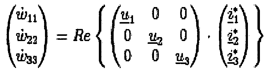
(44) in der wn , w22 und w33die zeitliche Ableitung der Energie auf der Netzseite in der drei Phasen, wwl bis wW3 die (44) in the w n, w 22 and w 33, the time derivative of the energy on the network side in the three phases, wl w to w W3
Phasenspannungen und ) bis /3 konjugiert komplexen
Netzströme, bezeichnen. Nach Umformung und Transformation unter Zurückgreifen auf das Gegensystem im Kreisstrom ergibt sich dann Phase voltages and) bis / 3 conjugated complex Mains currents. After transformation and transformation by resorting to the negative sequence system in a circulating current results
(45) (45)

Zur Modellierung des Umrichters 1 wird von dem bekannten Systemmodell - hier im dq-System ausgegangen: For the modeling of the inverter 1 is based on the known system model - here in the dq system:
(46) = AdqX + BdqUj Xdq = (isd lN„ k b&d fcj (46) = AdqX + BdqUj Xdq = (is d lN "k b & d fcj
Erfolgt hier eine Erweiterung auf das aß- und das Gegensystem des Kreisstromes, dann lautet der neue Zustandsvektor : If here an extension to the aß and the negative sequence of the circular current, then the new state vector is:

Für die Systemmatrix gilt dann: For the system matrix then:


(49) (49)
Gilt für
 Applies to
(50) dann gilt für (50) then applies to

Diese Verknüpfung kann durch die Rücktransformation T^'(t) ausgedrückt werden. So gilt für This link can be expressed by the inverse transformation T ^ '(t). So applies to
(52)
 (52)
(52)
Das Systemmodell A,ß(/) ist somit ein zeitvariantes System. Da sich periodisch wiederholt, spricht man von einem periodisch zeitvarianten System, oder PLTV-System (Periodic Linear Time-Variant System) . Definiert man eine Matrix gemäß nachfolgender Gleichung (53) The system model A, ß (/) is thus a time-variant system. Since it repeats periodically, it is called a periodically time-variant system, or PLTV system (Periodic Linear Time-Variant System). Defining a matrix according to the following equation (53)

ÄPLTV (54)
 ÄPLTV (54)
beschreiben sowie die Zustandsvariable xPLTV und der describe as well as the state variable x PLTV and the
Eingangsvariable uPLTV mit
χριτν—
 Input variable u PLTV with χ ριτν-
Es sind Methoden bekannt, optimale Regler für PLTV-Systeme zu entwerfen. Darauf wird hier zurückgegriffen, um einen Methods are known for designing optimal regulators for PLTV systems. This is used here to one
gemeinschaftlichen Reglerentwurf für die gesamte Community regulator design for the entire
Umrichterregelung inklusive Energieregelung und Balancierung zu ermöglichen. Der entworfene Regler ersetzt die Funktion sämtlicher Regler, welche die entsprechenden Aufgaben vorher erfüllt haben. Detaillierte Beschreibungen einer Methode finden sich in Bittanti, S.; Colaneri, P.; De Nicoiao, G.: „The Periodic Riccati Equation": In: Bittanti, S. (Hrsg.); Laub, A. J. (Hrsg.); Willems, J. C. (Hrsg.): The Riccati Equation. Berlin: 1991 und Görges, Daniel; Izäk Michal; Liu Steven „Optimal Control of Systems with Resource Inverter control including power control and balancing to enable. The designed controller replaces the function of all controllers that have previously fulfilled the respective tasks. Detailed descriptions of a method can be found in Bittanti, S .; Colaneri, P .; De Nicoiao, G .: "The Periodic Riccati Equation": In: Bittanti, S. (ed.), Laub, AJ (ed.), Willems, JC (ed.): The Riccati Equation, Berlin: 1991 and Görges, Daniel; Izak Michal; Liu Steven "Optimal Control of Systems with Resource
Constraints" . In: Proceedings of the 46th IEEE Conference on Decision and Control, 2007, S. 1070-1075 Constraints. "In: Proceedings of the 46th IEEE Conference on Decision and Control, 2007, pp. 1070-1075
Alternativ zur Regelung der Energie der positiv-seitigen 2P und der negativ-seitigen 2N Drehspannungsquelle kann auch die Abweichung zwischen diesen Quellen Aw über ein Mitsystem im Kreisstrom - und zwar als reiner Kreiswirkstrom - geregelt werden. Die Matrix lautet dann: As an alternative to the regulation of the energy of the positive-side 2P and the negative-side 2N three-phase voltage source, the deviation between these sources Aw can also be regulated by means of a positive sequence in the circulating current - as a pure circular active current. The matrix is then:

(56)
Bei der Modellierung des Umrichters 1 aus Gleichung (54) ist APLTV immer konstant, BPLTV(t) ist periodisch-zeitvariant . Wird 512 mal pro Netzperiode abgetastet, gilt p=512. Weiter gilt (56) In the modeling of the inverter 1 of Equation (54), A PLTV is always constant, B PLTV (t) is periodically-time-variant. If sampled 512 times per network period, p = 512. Next applies
2π 2π
dann für die Abtastzeitpunkte tk=k . Das kontinuierliche co- p then for the sampling times t k = k. The continuous co-p
periodisch-zeitvariante System Ak , Bk sowie dessen Periodic-time variant system A k , B k and its
kontinuierliche Gewichtungsmatrizen Q, N, R können wie bekannt diskretisiert werden, so dass man nachfolgend das zeitdiskrete Optimierungsproblem aus Gleichung (5.17) erhält: Continuous weighting matrices Q, N, R can be discretized as known, so that the time-discrete optimization problem is obtained from equation (5.17) below:
(57) (57)

Bei der oben angesprochenen bekannten Methode zum In the above-mentioned known method for
Reglerentwurf wird ein sogenanntes Lifting durchgeführt, das im Prinzip eine weitere Transformation darstellt, bei der das »-periodische PLTV-System in ein LTI-System (Linear Time- Invariant System) überführt wird. Dabei wird die Controller design, a so-called lifting is carried out, which is in principle another transformation, in which the »periodic PLTV system is converted into a LTI system (linear time-invariant system). Here is the
Zustandsgieichung über eine Periode, also p State equation over a period, so p
Diskretisierungsschritte gelöst:
x(k + 1) = kx(k) + Tbv{k) Discretization steps solved: x (k + 1) = k x (k) + T b v {k)
x(k + 2) =$k x{k + 1) + fh^ü(k + 1) x (k + 2) = $ k x {k + 1) + f h ^ u (k + 1)
=$fe l*fcx(fc) + $k+ifkÜ(k) +TkHÜ(k +1) = $ fe l * fc x (fc) + $ k + if k Ü (k) + T kH Ü (k +1)
... -I- fi+p_iö(fc +p - 1) mit *fc+Prfe =
 - · Φ*
 ... -I- f i + p _i (fc + p-1) with * fc + Prf e = - · Φ *
(58) (58)
Es können dann bekannte Optimalreglerentwurfsmethoden für LTI-Systeme angewendet werden. Das Ergebnis ist ein p- periodischer Regler. Die Regeleinheit 16 besitzt also Known optimal controller design methods for LTI systems can then be used. The result is a p-periodic controller. The control unit 16 thus has
periodisch-zeitvariante Verstärkungen. Die Implementierung kann zum Beispiels durch periodisches Umschalten der periodic-time variant gains. The implementation may be, for example, by periodically switching the
Reglermatrizen von Kv..K5n geschehen. Wird bei der erfindungsgemäßen Anordnung eine Eingangstruktur verwendet, wie sie in Figur 8 dargestellt ist, mit einer Regeleinheit 16 als periodischer Regler zwischen dem Regulator matrices of K v . K 5n happen. If, in the arrangement according to the invention, an input structure is used, as shown in FIG. 8, with a control unit 16 as a periodic regulator between the
Transformationsbaustein 21' bzw. der Aufbereitungseinheit 21A' und der Addiereinheit 15, dann lässt sich auch eine periodische Vorsteuereinheit 50 einsetzen mit einem Transformation module 21 'and the conditioning unit 21A' and the adding unit 15, then can also be a periodic pilot unit 50 use with a
Übertragungsverhalten N_{k) Transmission behavior N_ {k)
N{k)=Nv + Kk-Nx, (59) wobei Nv die Übertragungseigenschaft der Vorsteuereinheit 14 und Nx die Übertragungseigenschaft der Abbildungseinheit 14'
sowie Kk das Regelverhalten der Regelungseinheit 16 gemäß Figur 4 bezeichnen. N {k) = N v + K k -N x , where N v is the transmission characteristic of the pilot control unit 14 and N x is the transmission characteristic of the mapping unit 14 '. and K k denote the control behavior of the control unit 16 according to FIG.
Gemäß der Erfindung ist ein Beobachter ermöglicht, der According to the invention, an observer is enabled, the
Störungen, Oberschwingungen, Mess- und Stelltotzeiten Disturbances, harmonics, measuring and setting dead times
berücksichtigt. Durch einen solchen Beobachter kann eine Regelungsstruktur, die beispielsweise als Zustandsregelung ausgeführt ist, unverzögerte geschätzte Messwerte considered. By such an observer, a control structure, which is designed, for example, as a state control, instantaneous estimated measured values
bereitstellen und mithilfe der ermittelten Störungen und Oberschwingungen diese indirekt kompensieren. Damit erhält die Gesamtregelung die Fähigkeit zur Kompensation and indirectly compensate for them using the detected disturbances and harmonics. This gives the overall control the ability to compensate
verschiedener Oberschwingungen und Störungen im Mit-, Gegen- und αβ-System, ohne dass das Führungsverhalten negativ beeinflusst wird. different harmonics and perturbations in the mit, counter and αβ system, without affecting the leadership behavior.
Durch eine beschleunigte Regelung und eine schnelle Through an accelerated regulation and a fast
Störgrößenkompensation kann die Zwischenkreisenergieregelung und die Belancierung der Energien der oberen und unteren Drehspannungsquellen so verbessert werden, dass im Vergleich zu bekannten Lösungen entweder eine geringere Anzahl vonIn order to compensate for interference, the intermediate circuit control and the energization of the upper and lower voltage sources can be improved so that either a smaller number of
Submodulen pro Zweig oder eine geringere Kondensatorkapazität ausreicht, um dieselben Netzfehlerfälle zu beherrschen. Eine geringere Modulzahl oder eine geringere Kondensatorkapazität schlagen sich in geringeren Umrichterkosten nieder. Submodules per branch or a smaller capacitor capacity is sufficient to control the same network failure cases. A smaller number of modules or a smaller capacitor capacity results in lower converter costs.
Die Möglichkeit zur Oberschwingungskompensation ergibt darüber hinaus der Vorteil, dass eine wirtschaftliche Nutzung des Umrichters erzielt ist, da durch Erlangung dieser The possibility of harmonic compensation also provides the advantage that an economic use of the inverter is achieved because by obtaining this
Fähigkeit Netzfilter aktiver oder passiver Art eingespart werden können. Ability to save active or passive line filters.
Eine bessere Beherrschung von Netzfehlerfällen bedeutet eine geringere Ausfallzeit bzw. -Wahrscheinlichkeit, welches für
Netzbetreiber in wirtschaftlicher Hinsicht ein Vorteil sein kann.
A better control of network failure cases means a shorter downtime or probability, which for Network operator can be an advantage in economic terms.
Claims
Patentansprüche claims
1. Verfahren zum Regeln eines steuerbare Leistungshalbleiter aufweisenden Umrichters (1), bei dem 1. A method for controlling a controllable power semiconductor having inverter (1), in which
- Zustandsistwerte x(k) , die den Zustand des Umrichters (1) beschreiben, mit Zustandssollwerten xSoi, (k) unter - State actual values x (k), which describe the state of the inverter (1), with state setpoints x So i, (k) under
Gewinnung von Regeldifferenzwerten verglichen werden, die Regeldifferenzwerte einer Regelungseinheit (16) zugeführt werden, die an ihrem Ausgang Obtaining control differential values which are supplied to control difference values of a control unit (16) at its output
Stellspannungswerte u(k) erzeugt, und Actuating voltage values u (k) are generated, and
eine Steuerelektronik (19) in Abhängigkeit der an electronic control system (19) in dependence of
Stellspannungswerte u(k) Steuersignale bereitstellt und an die Leistungshalbleiter (S1,S2) des Umrichters (1) überträgt, wobei die Regelungseinheit (16) solche Control voltage values u (k) provides control signals and transmits to the power semiconductors (S1, S2) of the inverter (1), wherein the control unit (16) such
Stellspannungswerte u(k) generiert, dass die Rated voltage values u (k) generated that the
Regeldifferenzwerte möglichst klein werden, Control difference values become as small as possible,
d a d u r c h g e k e n n z e i c h n e t , dass d a d u r c h e c e n c i n e s that
die Zustandsistwerte x{k) von einer Beobachtereinheit (21) ausgehend von den Stellspannungswerten u(k) und unter Berücksichtigung von gemessenen Stromwerten x(k) berechnet werden, the actual state values x {k) are calculated by an observer unit (21) on the basis of the manipulated voltage values u (k) and taking into account measured current values x (k),
Zustandszwischenkreisenergieistwerte w(k) von einer Schätzereinheit (21A) unter Berücksichtigung von State intermediate energy values w (k) from an estimator unit (21A) taking into account
gemessenen Zwischenkreisenergiewerten w(k) der positiv- seitigen (2P) und der negativ-seitigen (2N) measured intermediate circuit energy values w (k) of the positive-side (2P) and the negative-side (2N)
Drehspannungsquelle des Umrichters (1) berechnet werden, wobei die Beobachtereinheit (21) und die Schätzereinheit (21A) den Umrichter (1) modellieren, so dass die The inverter unit (21) and the estimator unit (21A) model the inverter (1), so that the
berechneten Zustandsstromistwerte x(k) und calculated state current actual values x (k) and
Zustandszwischenkreisenergieistwerte w(k) im State intermediate circuit energy actual values w (k) in
eingeschwungenen Zustand den fehlerfreien Strom- und Zwischenkreisenergiewerten entsprechen, und
die fehlerfreien Strom- und Zwischenkreisenergiewerte x(k) , w(k) einer als periodischer Regler mit periodisch- zeitvarianter Verstärkung ausgebildeten Regelungseinheit (16) zugeführt werden. steady state correspond to the fault-free current and DC link energy values, and the error-free current and intermediate circuit energy values x (k), w (k) are supplied to a control unit (16) designed as a periodic controller with periodically variable amplification.
Verfahren nach Anspruch 1, Method according to claim 1,
a d u r c h g e k e n n z e i c h n e t, dass a d u r c h e c i n c e s that
eine Beobachtereinheit (21) mit einem periodisch- zeitvarianten Systemmodell verwendet wird, das ausgehend von der allgemeinen Zustandsgieichung an observer unit (21) with a periodically time-variant system model is used, which is based on the general equation of state
x = A-x + B u x = A-x + B u
mit x als Zustandsvariable , x als zeitlicher Ableitung der Zustandsvariablen, A als Systemmatrix, B als with x as the state variable, x as the time derivative of the state variable, A as the system matrix, B as
Eingangsmatrix und u als Eingangsvariable eine Input matrix and u as input variable one
zeitinvariante Systemmatrix APLTV und eine zeitvariante Eingangsmatrix BPLTV(t) aufweist mit time-invariant system matrix A PLTV and a time-variant input matrix B PLTV (t) has with

wobei x für den gemessenen, park-transformierten Strom, xaß für den alpha-beta-transformierten und xüq-> für den zweifach park-rücktransformierten gemessenen Strom where x is the measured, park-transformed current, x ate for the alpha-beta-transformed and x Ueq - measured> for the doubly-park back-transformed current
(Gegensystem) , waß für die alpha-beta-transformierten, gemessenen Zwischenkreisenergiewertesummen von oberer und unterer Drehspannungsquelle und wdq-< für die alpha- beta-transformierten, gemessenen (NPS), w ate for the alpha-beta-transformed measured intermediate-circuit energy values sums of upper and lower three-phase voltage source and w dq - <for the alpha- beta-transformed, measured
Zwischenkreisenergiewertedifferenzen zwischen oberer und unterer Drehspannungsquelle und w für die gemessenen Zwischenkreisenergiewerte des gesamten Umrichters steht.
Intercooler energy differences between upper and lower three-phase voltage source and w stands for the measured intermediate circuit energy values of the entire converter.
3. Verfahren nach Anspruch 1 oder 2, 3. The method according to claim 1 or 2,
d a d u r c h g e k e n n z e i c h n e t , dass d a d u r c h e c e n c i n e s that
die Zustandssollwerte Stromsollwerte xSou(k) und the state setpoints current setpoints x So u (k) and
Zwischenkreisenergiesollwerte wSoll(k) sind. . Verfahren zum Regeln eines steuerbare Leistungshalbleiter aufweisenden Umrichters (1), bei dem Intermediate circuit energy setpoints w Soll (k). , Method for controlling a controllable power semiconductor having converter (1), in which
Zustandsistwerte x(k) , die den Zustand des Umrichters (1) beschreiben, mit Zustandssollwerten xs„n(k) unter Condition actual values x (k), which describe the state of the inverter (1), with state setpoints x s "n (k) under
Gewinnung von Regeldifferenzwerten verglichen werden, die Regeldifferenzwerte einer Regelungseinheit (16) zugeführt werden, die an ihrem Ausgang Obtaining control differential values which are supplied to control difference values of a control unit (16) at its output
Stellspannungswerte u(k) erzeugt, und Actuating voltage values u (k) are generated, and
eine Steuerelektronik (19) in Abhängigkeit der an electronic control system (19) in dependence of
Stellspannungswerte (k) Steuersignale bereitstellt und an die Leistungshalbleiter (S1,S2) des Umrichters (1) überträgt, wobei die Regelungseinheit (16) solche Actuating voltage values (k) provides control signals and transmits them to the power semiconductors (S1, S2) of the converter (1), the control unit (16) having such
Stellspannungswerte u(k) generiert, dass die Rated voltage values u (k) generated that the
Regeldifferenzwerte möglichst klein werden, Control difference values become as small as possible,
d a d u r c h g e k e n n z e i c h n e t , dass d a d u r c h e c e n c i n e s that
die Zustandsistwerte x(k) von einer Beobachtereinheit (21) ausgehend von den Stellspannungswerten u(k) und unter Berücksichtigung von gemessenen Stromwerten x{k) berechnet werden, the state actual values x (k) are calculated by an observer unit (21) on the basis of the manipulated voltage values u (k) and taking into account measured current values x {k),
Zustandszwischenkreisenergieistwerte w(k) von einer Schätzereinheit (21A) unter Berücksichtigung von State intermediate energy values w (k) from an estimator unit (21A) taking into account
gemessenen Zwischenkreisenergiewerten w(k) der positiv- seitigen (2P) und der negativ-seitigen (2N) measured intermediate circuit energy values w (k) of the positive-side (2P) and the negative-side (2N)
Drehspannungsquelle des Umrichters (1) berechnet werden, wobei die Beobachtereinheit (21) und die Schätzereinheit (21A) den Umrichter (1) modellieren, so dass die
berechneten Zustandsstromistwerte x(k) und The inverter unit (21) and the estimator unit (21A) model the inverter (1), so that the calculated state current actual values x (k) and
Zustandszwischenkreisenergiewerte der Gesamtenergie des Umrichters und der Differenz der State intermediate circuit energy values of the total energy of the inverter and the difference of
Zwischenkreisenergiewerte w(k) der positiv-seitigen (2P) und der negativ-seitigen (2N) Drehspannungsquelle des Inter-circuit energy values w (k) of the positive-side (2P) and the negative-side (2N) three-phase voltage source of the
Umrichters (1) im eingeschwungenen Zustand den Inverter (1) in the steady state the
fehlerfreien Strom- und Zwischenkreisenergiewerten entsprechen, und Correct fault current and DC link energy values, and
die fehlerfreien Strom- x{k) und the error-free current x {k) and
Zwischenkreisenergiewerte x(k) einer als periodischer Intercircuit energy values x (k) one as periodic
Regler mit periodisch-zeitvarianter Verstärkung Controller with periodic time-variant amplification
ausgebildeten Regelungseinheit zugeführt werden. trained control unit to be supplied.
5. Verfahren nach Anspruch 4, 5. The method according to claim 4,
d a d u r c h g e k e n n z e i c h n e t , dass d a d u r c h e c e n c i n e s that
die Zustandssollwerte Stromsollwerte xSou(k) und the state setpoints current setpoints x So u (k) and
ZwisehenkreisenergieSollwerte sind . Intermediate circle energy target values are.
6. Verfahren nach einem der vorangehenden Ansprüche, 6. The method according to any one of the preceding claims,
d a d u r c h g e k e n n z e i c h n e t , dass d a d u r c h e c e n c i n e s that
die Zustandssollwerte mittels einer periodisch the state setpoints by means of a periodic
arbeitenden Vorsteuereinheit (N) aus vorgegebenen working pilot unit (N) from predetermined
Sollwerten gebildet werden. 7. Verfahren nach einem der vorangehenden Ansprüche, Setpoints are formed. 7. The method according to any one of the preceding claims,
d a d u r c h g e k e n n z e i c h n e t, dass d a d u r c h e c e n c i n e s that
bei dem periodischen Regler die periodisch-zeitvariante Verstärkung mittels periodischen Umschaltens von in the periodic controller, the periodic-time variant gain by means of periodic switching of
Reglermatrizen vorgenommen wird. Regulator matrices is made.
8. Verfahren nach einem der vorangehenden Ansprüche, 8. The method according to any one of the preceding claims,
d a d u r c h g e k e n n z e i c h n e t, dass
die Beobachtereinheit (21) Störungseffekte characterized in that the observer unit (21) Fault effects
berücksichtigt, so dass die Zustandsstromistwerte x(k) im eingeschwungenen Zustand den von Störungseffekten befreiten Strommesswerten entsprechen. so that the state current actual values x (k) in the steady state correspond to the current measured values which have been freed from interference effects.
9. Verfahren nach Anspruch 8, 9. The method according to claim 8,
d a d u r c h g e k e n n z e i c h n e t , dass d a d u r c h e c e n c i n e s that
die Beobachtereinheit (21) neben den im eingeschwungenen Zustand fehlerfreien Zustandsstromistwerten x[k) the observer unit (21) next to the steady state actual current values x [k) in the steady state
gestörte Zustandsmodellmesswerte yd(k) bereitstellt, die messbaren Zustandsmesswerten y d{k) entsprechen, wobei die Zustandsmodellmesswerte yd(k) mit durch Messungen erhaltenen Zustandsmesswerten y d(k) unter Gewinnung einer Modellmesswertabweichung verglichen werden, die Modellmesswertabweichung der Modelleinheit (22) provides disturbed state model values y d (k), the measurable state measuring values y d {k), wherein the state model values y d (k) w ith state measurement values y d (k) obtained by measurements to obtain a model measurement error are compared (the model measured value deviation of the model unit 22)
eingangsseitig zugeführt und die Modellierung so supplied on the input side and the modeling so
durchgeführt wird, dass die Modellmesswertabweichung möglichst klein wird. 10. Verfahren nach Anspruch 9, is carried out that the model measured value deviation is as small as possible. 10. The method according to claim 9,
d a d u r c h g e k e n n z e i c h n e t, dass d a d u r c h e c e n c i n e s that
die Modellmesswertabweichung der the model measurement deviation of
Modelleinheit (22) über eine Rückführungseinheit (25) zugeführt, welche die Modellmesswertabweichung Model unit (22) via a feedback unit (25) supplied, which the model measured value deviation
verstärkt. strengthened.
11. Verfahren nach einem der Ansprüche 8 oder 10, 11. The method according to any one of claims 8 or 10,
d a d u r c h g e k e n n z e i c h n e t, dass d a d u r c h e c e n c i n e s that
das Berücksichtigen von Störungseffekten, das the consideration of disturbance effects, the
Berücksichtigen von Fehlern, die in einem mit dem Considering errors that are in one with the
Umrichter (1) verbundenen elektrischen Inverter (1) connected electrical
Energieversorgungsnetz beruhen, und das Berücksichtigen
WO 2011/098100 _. n PCT/EP2010/000967 von Fehlern umfasst, die durch den Umrichter (1) verursacht werden. Energy supply network based, and taking into account WO 2011/098100. n PCT / EP2010 / 000967 of faults caused by the inverter (1).
2. Verfahren nach einem der Ansprüche 8 bis 11, 2. Method according to one of claims 8 to 11,
a d u r c h g e k e n n z e i c h n e t, dass a d u r c h e c i n c e s that
die Beobachtereinheit (21) mit Hilfe eines the observer unit (21) with the help of a
Zustandraummodells gemäß State space model according to
p{k + \) = -xp{k) + Tup{k) yd(k) = np-xP(k) p {k + \) = -x p {k) + Tu p {k) y d (k) = n p -x P (k)
modelliert wird, wobei xP(k) einem Zustandsvektor des Umrichters (1) einschließlich gestörter Zustände, up(k) einem Vektor der Stellspannungen, Φ, Γ und H where x P (k) is a state vector of the converter (1) including faulted states, u p (k) a vector of the control voltages, Φ, Γ and H
Modellmatrizen und yd{k) einem Vektor von mit Störungen behafteten Zustandsmodellmesswerten entsprechen. Model matrices and y d {k) correspond to a vector of perturbed state model metrics.
3. Verfahren nach einem der vorangehenden Ansprüche, a d u r c h g e k e n n z e i c h n e t, dass 3. The method according to any one of the preceding claims, a d u r c h e c e n e c e s in that e
die Beobachtereinheit (21) Verzögerungseffekte the observer unit (21) delay effects
berücksichtigt, so dass die Zustandsstromistwerte x(k) von Störungs- und Verzögerungseffekten befreiten unverzögerten und ungestörten Strommesswerten so that the state current actual values x (k) of undelayed and undisturbed current measurement values are freed from disturbance and delay effects
entsprechen . correspond .
4. Verfahren nach Anspruch 13, 4. The method according to claim 13,
a d u r c h g e k e n n z e i c h n e t, dass a d u r c h e c i n c e s that
die Beobachtereinheit (21) neben den unverzögerten Zustandsistwerten x(k) verzögerte delayed the observer unit (21) in addition to the instantaneous state actual values x (k)
Zustandsmodellmesswerte yd(k) bereitstellt, die Provides state model metrics y d (k) that
messbaren Zustandsmesswerten y { ) entsprechen, wobei die Zustandsmodellmesswerte y (k) mit durch Messungen erhaltenen Zustandsmesswerten y (k) unter Gewinnung
einer Modellmesswertabweichung verglichen werden, die Modellmesswertabweichung der Modelleinheit (22) measurable state measurement values y {), wherein the state model measurements y (k) with state measurements y (k) obtained by measurements to obtain a model measurement deviation, the model measurement deviation of the model unit (22)
eingangsseitig zugeführt und die Modellierung so supplied on the input side and the modeling so
durchgeführt wird, dass die Modellmesswertabweichung möglichst klein wird. is carried out that the model measured value deviation is as small as possible.
15. Verfahren nach Anspruch 13 oder 14, 15. The method according to claim 13 or 14,
d a d u r c h g e k e n n z e i c h n e t, dass d a d u r c h e c e n c i n e s that
die Modellmesswertabweichung der the model measurement deviation of
Modelleinheit (22) über eine Rückführungseinheit (25) zugeführt wird, welche die Modellmesswertabweichung verstärkt . Model unit (22) via a feedback unit (25) is supplied, which enhances the model measured value deviation.
16. Verfahren nach einen der Ansprüche 13 bis 15, 16. The method according to any one of claims 13 to 15,
d a d u r c h g e k e n n z e i c h n e t, dass d a d u r c h e c e n c i n e s that
das Berücksichten von Verzögerungseffekten, das taking into account delay effects, the
Berücksichtigen von Messverzögerungen, die bei der digitalen Erfassung der Zustandsgrößen des Umrichters (1) entstehen, und das Berücksichtigen von Take into account the measurement delays that occur during the digital acquisition of the state variables of the converter (1) and the consideration of
Stellverzögerungen umfasst, die von der Steuerelektronik Deceleration time includes that of the control electronics
(19) verursacht werden. (19).
17. Verfahren nach einem der Ansprüche 13 bis 16, 17. The method according to any one of claims 13 to 16,
d a d u r c h g e k e n n z e i c h n e t, dass d a d u r c h e c e n c i n e s that
- bei der Erfassung der Zustandsmesswerte yd{k) die - in the acquisition of the state measured values y d {k) the
Zustandsgröße des Umrichters (1) gemessen, das dabei gewonnene Messsignale in Abtastschritten unter Gewinnung von Abtastwerten fortlaufend abgetastet und die State variable of the inverter (1) measured, the measurement signals thereby obtained in scanning steps continuously scanned to obtain samples and the
Abtastwerte anschließend digitalisiert werden, wobei die Modellierung der sich dabei einstellenden Samples are then digitized, the modeling of the thereby adjusting
Messverzögerungen unter der Annahme erfolgt, dass die Messverzögerung einer Zeitdauer von mehreren Measurement delays under the assumption that the measurement delay of a period of several
Abtastschritten entspricht.
18. Verfahren nach Anspruch 17 Scanning steps corresponds. 18. The method according to claim 17
d a d u r c h g e k e n n z e i c h n e t, dass d a d u r c h e c e n c i n e s that
eine Messverzögerung von vier Abtastschritten berücksichtigt wird . a measurement delay of four sampling steps is taken into account.
19. Verfahren nach einem der Ansprüche 13 bis 18, 19. The method according to any one of claims 13 to 18,
d a d u r c h g e k e n n z e i c h n e t , dass d a d u r c h e c e n c i n e s that
eine Stellverzögerung r gemäß a set delay r according to
τ = (ΐ-\)Τ+τ' τ = (ΐ - \) Τ + τ '
modelliert wird, wobei / der Anzahl der Abtastschritte entspricht, deren Summe kleiner ist als die is modeled, where / corresponds to the number of sampling steps whose sum is smaller than that
Stellverzögerung r, und τ' als Restanteil kürzer ist als die' Zeitdauer T zwischen zwei Abtastschritten k. Set delay r, and τ 'as a residual proportion is shorter than the ' time period T between two sampling steps k.
20. Verfahren nach Anspruch 19, 20. The method according to claim 19,
d a d u r c h g e k e n n z e i c h n e t, dass d a d u r c h e c e n c i n e s that
bei der Modellierung der Stellverzögerung zwei Abtastschritte berücksichtigt werden. 21. Verfahren nach einem der Ansprüche 13 bis 20, be considered in the modeling of the delay two sampling steps. 21. The method according to any one of claims 13 to 20,
d a d u r c h g e k e n n z e i c h n e t, dass d a d u r c h e c e n c i n e s that
der Umrichter mit Hilfe eines Zustandraummodells the inverter using a state space model
gemäß according to
x(k + \) = <&x(k) +Tu{k) x (k + \) = <& x (k) + Tu {k)
yd(k) = Hx(k) modelliert wird, wobei x (k) einem Zustandsvektor desy d (k) = Hx (k), where x (k) is a state vector of the
Umrichters einschließlich verzögerten Zuständen, u(k) einem Vektor der Stellspannungen, Φ, Γ und H Inverter including delayed states, u (k) a vector of the control voltages, Φ, Γ and H
Modellmatrizen und yd(k) einem Vektor von mit Model matrices and y d (k) a vector of with
Verzögerungen behafteten Zustandsmodellmesswerten entsprechen .
Corresponding to delayed state model measured values.
. Verfahren nach einem der vorangehenden Ansprüche, a d u r c h g e k e n n z e i c h n e t, dass , Method according to one of the preceding claims, characterized in that a
Zustands-Zwischenkreisenergiewerte w(k) mittels einer auf ein Signalmodell der Zwischenkreisenergiewerte zurück greifenden Schätzereinheit (21A) aus gemessenen State intermediate circuit energy values w (k) are measured by means of an estimator unit (21A) which is based on a signal model of the intermediate circuit energy values
Zwischenkreisenergiewerten ermittelt werden, wobei die Schätzereinheit (21A) die Parameter des Signalmodells der Zwischenkreisenergiewerte w(k) unter Ermittlung jeweils einer Zustands-Zwischenkreisenergiewerte w(k) der Intermediate circuit energy values, wherein the estimator unit (21A) determines the parameters of the signal model of the intermediate circuit energy values w (k) while determining a respective state intermediate circuit energy values w (k) of the
positiv-seitigen und der negativ-seitigen positive-sided and negative-sided
Drehspannungsquelle des Umrichters (1) darstellenden Gleichgröße errechnet, und Calculated three-phase voltage source of the inverter (1) representing equal size, and
Zustands-Zwischenkreisenergiewerte w(k) zusätzlich zu den Zustands-Stromwerten x(k) der Regelungseinheit (16) zugeführt werden. State intermediate circuit energy values w (k) are supplied to the control unit (16) in addition to the state current values x (k).
. Verfahren nach Anspruch 22, , Method according to claim 22,
a d u r c h g e k e n n z e i c h n e t , dass a d u r c h e c i n c e s that
die Zustands-Zwischenkreisenergiewerte der positiv- seitigen und der negativ-seitigen the state intermediate circuit energy values of the positive-side and the negative-side
Leistungshalbleiterventilzweige (2) des Umrichters (1) jeweils für sich erfasst werden, Leistungshalbleiterventilzweige (2) of the inverter (1) are each detected separately,
mittels jeweils eines Parameter-Schätzers by means of one parameter estimator each
(33, 34, 35; 36, 37, 38) der Schätzereinheit (21A) die (33, 34, 35, 36, 37, 38) of the estimator unit (21A)
Parameter des Signalmodells der Zwischenenergiewerte w(k) errechnet werden, Parameters of the signal model of the intermediate energy values w (k) are calculated,
die jeweils einen Gleichanteil beschreibenden Parameter der positiv-seitigen und der negativ-seitigen each describing a DC component parameters of the positive-side and the negative-side
Leistungshalbleiterventilzweige (2) jeweils für sich unter Bildung der Zwischenkreisenergie-Gleichgrößen addiert werden. Power semiconductor valve branches (2) are added together in each case to form the DC link energy DC magnitudes.
Verfahren nach Anspruch 23,
d a d u r c h g e k e n n z e i c h n e t, dass Parameter-Schätzer mit rekursivem Algorithmus verwendet werden . 25. Verfahren nach Anspruch 23 oder 24, Method according to claim 23, characterized in that parameter estimators are used with recursive algorithm. 25. The method according to claim 23 or 24,
d a d u r c h g e k e n n z e i c h n e t , dass d a d u r c h e c e n c i n e s that
als Schätzer ein Parameter-Schätzer mit einem as an estimator a parameter estimator with a
Schwingungsmodell w(t) für die Zwischenkreisenergiewerte w(t) = A0+Aki*cos (koot ) +Ak2*sin (kcat ) für k=l bis n Oscillation model w (t) for the intermediate circuit energy values w (t) = A 0 + A k i * cos (koot) + A k2 * sin (kcat) for k = 1 to n
verwendet wird, is used,
in dem A0 den Gleichanteil der in which A 0 is the DC component of
Zwischenkreisenergiewerte und Aki und Ak2 weitere Parameter des Schwindungsmodells sowie ω die Zwischenkreiseergiewerte and A k i and A k2 other parameters of the shrinkage model and ω the
Kreisfrequenz eines mit dem Umrichter (1) verbundenen Wechselspannungsnetzes angibt. Circular frequency of an AC voltage network connected to the converter (1) indicates.
26. Verfahren nach Anspruch 24 oder 25, 26. The method according to claim 24 or 25,
d a d u r c h g e k e n n z e i c h n e t, dass d a d u r c h e c e n c i n e s that
ein Schwingungsmodell mit zeitabhängigen Parametern A0(t) bis Ak2(t) verwendet wird. a vibration model with time-dependent parameters A 0 (t) to A k2 (t) is used.
27. Verfahren nach Anspruch 26, 27. The method according to claim 26,
d a d u r c h g e k e n n z e i c h n e t, dass d a d u r c h e c e n c i n e s that
die Zeitabhängigkeit der Parameter durch eine the time dependence of the parameters by a
lineare Funktion oder eine Exponentialfunktion linear function or an exponential function
vorgegeben wird. is given.
28. Verfahren nach Anspruch 24 oder 25, 28. The method according to claim 24 or 25,
d a d u r c h g e k e n n z e i c h n e t, dass d a d u r c h e c e n c i n e s that
- ein Schwingungsmodell mit zeitlich konstanten - A vibration model with temporally constant
Parametern A0 bis Ak2 verwendet wird. Parameters A 0 to A k2 is used.
29. Verfahren nach einem der vorangehenden Ansprüche, d a d u r c h g e k e n n z e i c h n e t , dass
als Umrichter (1) ein Multilevel-Umrichter verwendet wird, der zu einer Brückenschaltung miteinander verbundene 29. The method according to any one of the preceding claims, characterized in that As converter (1) a multilevel inverter is used, which is connected to a bridge circuit
Leistungshalbleiterventilzweige (2) aufweist, wobei jeder Leistungshalbleiterventilzweige (2) aus einer Reihenschaltun von Submodulen (8) besteht und jedes Submodul (8) eine Power semiconductor valve branches (2), wherein each power semiconductor valve branches (2) consists of a series of sub-modules (8) and each sub-module (8) one
Schaltung (9) von Leistungshalbleitern sowie eine parallel dazu angeordnete Kondensatoreinheit (10) umfasst. Circuit (9) of power semiconductors and a parallel arranged capacitor unit (10).
30. Anordnung zur Durchführung des Verfahrens nach einem der Ansprüche 1 bis 3 und 6 bis 29 Regeln eines Umrichters (1) mit einer Brückenschaltung von Phasenmodulzweigen mit jeweil einer Reihenschaltung von Submodulen mit jeweils einer 30. Arrangement for carrying out the method according to one of claims 1 to 3 and 6 to 29 Rules of an inverter (1) with a bridge circuit of phase module branches each having a series connection of submodules each having one
Halbleiterschaltung mit angeschlossenem Kondensator, mit Semiconductor circuit with attached capacitor, with
einer mit ihrem Eingang mit dem Messwerteausgang des Umrichters verbundenen Regelungseinheit (16) , die an ihrem Ausgang Stellspannungswerte u(k) erzeugt, und einer der Regelungseinheit (16) nachgeordneten a with its input to the measured value output of the inverter connected control unit (16) which generates at its output actuating voltage values u (k), and one of the control unit (16) downstream
Steuerelektronik (19) , die in Abhängigkeit der Control electronics (19), which depend on the
Stellspannungswerte u(k) Steuersignale bereitstellt und an die Leistungshalbleiter (S1,S2) des Umrichters (1) überträgt, Actuating voltage values u (k) provides control signals and transmits them to the power semiconductors (S1, S2) of the converter (1),
d a d u r c h g e k e n n z e i c h n e t , dass d a d u r c h e c e n c i n e s that
zwischen dem Messwerteausgang des Umrichters (1) und dem Eingang der Regelungseinheit (16) eine Beobachtereinheit (21) liegt, die die Zustandsistwerte x{k) ausgehend von den Stellspannungswerten u(k) und unter Berücksichtigung von gemessenen Stromwerten x(k) berechnet, between the measured value output of the converter (1) and the input of the control unit (16) is an observer unit (21) which calculates the actual state values x {k) from the control voltage values u (k) and taking into account measured current values x (k),
zwischen dem Messwerteausgang des Umrichters (1) und dem Eingang der Regelungseinheit (16) eine Schätzereinheit (21A) liegt, die Zustandszwischenkreisenergieistwerte w(k) unter Berücksichtigung von gemessenen between the measured value output of the converter (1) and the input of the control unit (16) is an estimator unit (21A), the intermediate state energy actual values w (k) taking into account measured
Zwischenkreisenergiewerten w(k) der positiv-seitigen Inter-circuit energy values w (k) of the positive-side
(2P) und der negativ-seitigen (2N) Drehspannungsquelle
2011/098100 r i- PCT/EP2010/000967 o b des Umrichters (1) berechnet, wobei die (2P) and the negative-side (2N) three-phase source 2011/098100 ri - PCT / EP2010 / 000967 whether the converter (1) is calculated, the
Beobachtereinheit (21) und die Schätzereinheit (21A) den Umrichter (1) modellieren, so dass die berechneten Observer unit (21) and the estimator unit (21A) model the inverter (1), so that the calculated
Zustandsstromistwerte x(k) und State current actual values x (k) and
Zustandszwischenkreisenergieistwerte w(k) im State intermediate circuit energy actual values w (k) in
eingeschwungenen Zustand den fehlerfreien Strom- und Zwischenkreisenergiewerten entsprechen, und steady state correspond to the fault-free current and DC link energy values, and
die fehlerfreien Strom- und Zwischenkreisenergiewerte , x(k) , w(k) , einer als periodischer Regler mit periodisch- zeitvarianter Verstärkung ausgebildeten Regelungseinheit zugeführt werden. the error-free current and intermediate circuit energy values, x (k), w (k), are supplied to a control unit designed as a periodic controller with periodically variable amplification.
Anordnung nach Anspruch 30, Arrangement according to claim 30,
d u r c h g e k e n n z e i c h n e t, dass d e r c h e c i n e s that
eine Beobachtereinheit (21) mit einem periodisch- zeitvarianten Systemmodell verwendet wird, das ausgehend von der allgemeinen Zustandsgieichung an observer unit (21) with a periodically time-variant system model is used, which is based on the general equation of state
x = A x + B-u x = A x + B u
mit x als Zustandsvariable, x als zeitlicher Ableitung der Zustandsvariablen, A als Systemmatrix, B als with x as the state variable, x as the time derivative of the state variable, A as the system matrix, B as
Eingangsmatrix und u als Eingangsvariable eine Input matrix and u as input variable one
zeitinvariante Systemmatrix APLTV und eine zeitvariante Eingan smatrix BPLTV(t) aufweist mit time-invariant system matrix A PLTV and a time-variant input matrix B PLTV (t) has with
PLTVPLTV
wobei x für den gemessenen, park-transformierten Strom, xaß für den alpha-beta-transformierten und für den zweifach park-rücktransformierten gemessenen Strom
(Gegensystem) , waß für die alpha-beta-transformierten, gemessenen Zwischenkreisenergiewertesummen von oberer und unterer Drehspannungsquelle und für die alpha- beta-transformierten, gemessenen where x is the measured, park-transformed current, x aβ is the alpha-beta transformed, and the two-time inverse-transformed measured current (NPS), w ate for the alpha-beta-transformed measured intermediate-circuit energy values sums of upper and lower three-phase voltage source and for the alpha-beta-transformed, measured
Zwischenkreisenergiewertedifferenzen zwischen oberer und unterer Drehspannungsquelle und w für die gemessenen Zwischenkreisenergiewerte des gesamten Umrichters steht. Intercooler energy differences between upper and lower three-phase voltage source and w stands for the measured intermediate circuit energy values of the entire converter.
32. Anordnung zur Durchführung des Verfahrens nach einem der Ansprüche 4 und 5 sowie 6 bis 29 zum Regeln eines Umrichters32. Arrangement for carrying out the method according to one of claims 4 and 5 and 6 to 29 for controlling an inverter
(1) mit einer Brückenschaltung von Phasenmodulzweigen (2) mit jeweils einer Reihenschaltung von Submodulen (8) mit jeweils einer Halbleiterschaltung (9) mit angeschlossenem Kondensator(1) with a bridge circuit of phase module branches (2) each having a series connection of submodules (8) each having a semiconductor circuit (9) with a connected capacitor
(10), mit (10), with
- einer mit ihrem Eingang mit dem Messwerteausgang des - one with its input with the measured value output of the
Umrichters (1) verbundenen Regelungseinheit (16), die an ihrem Ausgang Stellspannungswerte u(k) erzeugt, und einer der Regelungseinheit (16) nachgeordneten Inverter (1) connected control unit (16) which generates at its output actuating voltage values u (k), and one of the control unit (16) downstream
Steuerelektronik (19), die in Abhängigkeit der Control electronics (19), which depend on the
Stellspannungswerte u(k) Steuersignale bereitstellt und an die Leistungshalbleiter (S1,S2) des Umrichters (1) überträgt , Actuating voltage values u (k) provides control signals and transmits them to the power semiconductors (S1, S2) of the converter (1),
d a d u r c h g e k e n n z e i c h n e t , dass d a d u r c h e c e n c i n e s that
zwischen dem Messwerteausgang des Umrichters (1) und dem Eingang der Regelungseinheit (16) eine Beobachtereinheit between the measured value output of the converter (1) and the input of the control unit (16) an observer unit
(21) liegt, die die Zustandsistwerte x{k) ausgehend von den Stellspannungswerten u(k) und unter Berücksichtigung von gemessenen Stromwerten x(k) berechnet, (21) which calculates the state actual values x {k) on the basis of the control voltage values u (k) and taking into account measured current values x (k),
zwischen dem Messwerteausgang des Umrichters (1) und dem Eingang der Regelungseinheit (16) eine Schätzereinheit between the measured value output of the converter (1) and the input of the control unit (16) an estimator unit
(21A) liegt, die Zustandszwischenkreisenergieistwerte w(k) unter Berücksichtigung von gemessenen
Zwischenkreisenergiewerten w(k) der positiv-seitigen (2P) und der negativ-seitigen (2N) Drehspannungsquelle des Umrichters (1) berechnet, wobei die (21A), the state intermediate energy actual values w (k) taking into consideration measured Calculated intermediate circuit energy values w (k) of the positive-side (2P) and the negative-side (2N) three-phase voltage source of the inverter (1), wherein the
Beobachtereinheit (21) und die Schätzereinheit (21A) den Umrichter (1) modellieren, so dass die berechneten Observer unit (21) and the estimator unit (21A) model the inverter (1), so that the calculated
Zustandsstromistwerte x(k) und State current actual values x (k) and
Zustandszwischenkreisenergiewerte der Gesamtenergie des Umrichters und der Differenz der State intermediate circuit energy values of the total energy of the inverter and the difference of
Zwischenkreisenergiewerte w(k) der positiv-seitigen (2P) und der negativ-seitigen (2N) Drehspannungsquelle des Inter-circuit energy values w (k) of the positive-side (2P) and the negative-side (2N) three-phase voltage source of the
Umrichters (1) im eingeschwungenen Zustand den Inverter (1) in the steady state the
fehlerfreien Strom- und Zwischenkreisenergiewerten entsprechen, und Correct fault current and DC link energy values, and
die fehlerfreien Strom- x(k) und the error-free current x (k) and
Zwischenkreisenergiewerte x(k) einer als periodischer Intercircuit energy values x (k) one as periodic
Regler mit periodisch-zeitvarianter Verstärkung Controller with periodic time-variant amplification
ausgebildeten Regelungseinheit zugeführt werden. trained control unit to be supplied.
33. Anordnung nach Anspruch 30 oder 31, 33. Arrangement according to claim 30 or 31,
d a d u r c h g e k e n n z e i c h n e t, dass d a d u r c h e c e n c i n e s that
eine ausgangsseitig mit einer dem periodischen Regler (16) vorgeordneten Summierschaltung (15) verbundene periodische Vorsteuereinheit (14') eine der Periode des Wechselstroms entsprechende Periode aufweist. a periodic pilot control unit (14 ') connected on the output side to a summing circuit (15) arranged upstream of the periodic regulator (16) has a period corresponding to the period of the alternating current.
34. Anordnung nach einem der Ansprüchen 30 oder 33, 34. Arrangement according to one of claims 30 or 33,
d a d u r c h g e k e n n z e i c h n e t, dass d a d u r c h e c e n c i n e s that
der periodische Regler (16) so ausgebildet ist, dass seine periodisch-zeitvariante Verstärkung mittels periodischen Umschaltens seiner Reglermatrizen erfolgt. the periodic controller (16) is designed such that its periodically-time-variant amplification takes place by means of periodically switching over its regulator matrices.
35. Anordnung nach einem der Ansprüche 30 bis 34, 35. Arrangement according to one of claims 30 to 34,
d a d u r c h g e k e n n z e i c h n e t, dass
die Beobachtereinheit (21) so ausgestattet ist, dass sie Zustandsistwerte x{k) ausgehend von den characterized in that the observer unit (21) is equipped to obtain state actual values x {k) from the
Stellspannungswerten u(k) und Zustandsmesswerten y d (k) unter Berücksichtigung von Störeffekten und/oder Actuating voltage values u (k) and state measured values y d (k) taking into account interference effects and / or
Verzögerungseffekten derart berechnet, dass die Delay effects calculated such that the
Zustandsistwerte x(k) von Störungseffekte befreiten und/oder ungestörten Strommesswerten im eingeschwungenen Zustand entsprechen. 36. Anordnung nach einem der Ansprüche 30 bis 35, Condition actual values x (k) correspond to interference-free and / or undisturbed current measured values in the steady state. 36. Arrangement according to one of claims 30 to 35,
d a d u r c h g e k e n n z e i c h n e t, dass d a d u r c h e c e n c i n e s that
an den Ausgang des Umrichters (1) eine das to the output of the inverter (1) a
Signalmodell von Zwischenkreisenergiewerten w(k) Signal model of intermediate circuit energy values w (k)
nachbildende Schätzereinheit (21A) angeschlossen ist und - die Beobachtereinheit (21) und die simulating estimator unit (21A) is connected and - the observer unit (21) and the
Schätzereinheit (21A) ausgangsseitig mit Ist-Eingängen der Regelungseinheit (16) verbunden sind. Estimator unit (21A) on the output side with actual inputs of the control unit (16) are connected.
37. Anordnung nach Anspruch 36, 37. Arrangement according to claim 36,
- bei einem Umrichter (1) mit sechs - at a converter (1) with six
Leistungshalbleiterventilzweigen (2) die Power semiconductor valve branches (2) the
Schätzereinheit (21A) für jeden der drei positiv- seitigen Leistungshalbleiterventilzweige (2) jeweils einen Schätzer (33, 34, 35) und für jeden der drei negativ-seitigen Leistungshalbleiterventilzweige (2) jeweils einen weiteren Schätzer (36, 37, 38) aufweist. An estimator unit (21A) has an estimator (33, 34, 35) for each of the three positive-side power semiconductor valve branches (2) and a further estimator (36, 37, 38) for each of the three negative-side power semiconductor valve branches (2).
38. Anordnung nach einem der Ansprüche 28 oder 35, 38. Arrangement according to one of claims 28 or 35,
die Beobachtereinheit (21) eine den Umrichter the observer unit (21) a the inverter
(1) nach bildende Modelleinheit (22) aufweist, die mit ihrem einen Eingang mit dem Ausgang der (1) according to the forming model unit (22), with its one input to the output of the
Regelungseinheit (16) und mit ihrem anderen Eingang mit
dem Ausgang einer Rückführungseinheit (25) verbunden ist , Control unit (16) and with its other input with connected to the output of a feedback unit (25),
die Rückführungseinheit (25) mit dem Ausgang the feedback unit (25) with the output
einer Summierschaltung (24) verbunden ist, die mit ihrem einen Eingang an den Ausgang des Umrichters (1) und mit ihrem weiteren Eingang an den Ausgang einer Ausschneideeinheit (23) angeschlossen ist, wobei die Ausschneideeinheit (23) mit dem Ausgang der a summing circuit (24) is connected, which is connected with its one input to the output of the inverter (1) and with its further input to the output of a Ausschneideeinheit (23), wherein the Ausschneideeinheit (23) with the output of
Modelleinheit (22) verbunden ist, und Model unit (22) is connected, and
- der Ausgang der Modelleinheit (22) über eine weitere Ausschneideeinheit (26) mit dem Eingang der - The output of the model unit (22) via another cutting unit (26) with the input of
Regelungseinheit (16) verbunden ist. Control unit (16) is connected.
39. Anordnung nach einem der Ansprüche 30 bis 38, 39. Arrangement according to one of claims 30 to 38,
d a d u r c h g e k e n n z e i c h n e t, dass d a d u r c h e c e n c i n e s that
der Umrichter (1) ein Multilevel-Umrichter ist, der zu einer Brückenschaltung miteinander verbundene the inverter (1) is a multilevel inverter connected to a bridge circuit
Leistungshalbleiterventilzweige (2) aufweist, wobei jeder Leistungshalbleiterventilzweig (2) aus einer Power semiconductor valve branches (2), wherein each power semiconductor valve branch (2) consists of a
Reihenschaltung von Submodulen (8) besteht und jedes Series connection of submodules (8) exists and each
Submodul (8) eine Schaltung (9) von Leistungshalbleitern sowie eine parallel dazu angeordnete Kondensatoreinheit (10) umfasst.
Submodule (8) comprises a circuit (9) of power semiconductors and a capacitor unit (10) arranged parallel thereto.
Priority Applications (3)
| Application Number | Priority Date | Filing Date | Title |
|---|---|---|---|
| PCT/EP2010/000967 WO2011098100A1 (en) | 2010-02-11 | 2010-02-11 | Control of a modular converter having distributed energy stores by means of an observer for the currents and by means of an estimating unit for the intermediate circuit energy |
| EP10706925.4A EP2534748B1 (en) | 2010-02-11 | 2010-02-11 | Control of a modular multilevel converter with an observer for the currents and an estimator for the energy of the intermediate circuit |
| US13/578,664 US8837185B2 (en) | 2010-02-11 | 2010-02-11 | Control of a modular converter having distributed energy stores with the aid of an observer for the currents and an estimating unit for the intermediate circuit energy |
Applications Claiming Priority (1)
| Application Number | Priority Date | Filing Date | Title |
|---|---|---|---|
| PCT/EP2010/000967 WO2011098100A1 (en) | 2010-02-11 | 2010-02-11 | Control of a modular converter having distributed energy stores by means of an observer for the currents and by means of an estimating unit for the intermediate circuit energy |
Publications (1)
| Publication Number | Publication Date |
|---|---|
| WO2011098100A1 true WO2011098100A1 (en) | 2011-08-18 |
Family
ID=43016112
Family Applications (1)
| Application Number | Title | Priority Date | Filing Date |
|---|---|---|---|
| PCT/EP2010/000967 WO2011098100A1 (en) | 2010-02-11 | 2010-02-11 | Control of a modular converter having distributed energy stores by means of an observer for the currents and by means of an estimating unit for the intermediate circuit energy |
Country Status (3)
| Country | Link |
|---|---|
| US (1) | US8837185B2 (en) |
| EP (1) | EP2534748B1 (en) |
| WO (1) | WO2011098100A1 (en) |
Cited By (6)
| Publication number | Priority date | Publication date | Assignee | Title |
|---|---|---|---|---|
| CN103078480A (en) * | 2013-01-27 | 2013-05-01 | 中国科学院电工研究所 | Circulation control method of modular multilevel converter |
| EP2677653A1 (en) * | 2012-06-19 | 2013-12-25 | Siemens Aktiengesellschaft | Modular multilevel converter |
| WO2014198343A1 (en) * | 2013-06-14 | 2014-12-18 | Abb Technology Ltd | Arrangement, method and computer program product concerned with tapping of power from a dc power line to an ac power line |
| CN104584414A (en) * | 2012-08-28 | 2015-04-29 | Abb技术有限公司 | Controlling modular converter in two stages |
| EP3506485A1 (en) * | 2017-12-26 | 2019-07-03 | Ikerlan, S. Coop | Method for controlling a power converting and a system thereof |
| EP2801149B1 (en) | 2012-02-14 | 2022-11-30 | Siemens Aktiengesellschaft | Method for operating a multi-phase modular multi-level power converter |
Families Citing this family (29)
| Publication number | Priority date | Publication date | Assignee | Title |
|---|---|---|---|---|
| WO2013182866A2 (en) * | 2012-06-07 | 2013-12-12 | Farkas Gabor | Control method, control device and mobile electric power storage apparatus |
| JP5993675B2 (en) * | 2012-09-14 | 2016-09-14 | 株式会社日立製作所 | Power converter, power conversion system, and control method for power converter |
| WO2014046555A1 (en) * | 2012-09-21 | 2014-03-27 | Auckland Uniservices Limited | Improvements in or relating to modular multi-level converters |
| EP2733842B1 (en) * | 2012-11-15 | 2018-07-04 | ABB Schweiz AG | Controlling an electrical converter |
| CN103248261B (en) * | 2013-05-24 | 2015-05-20 | 哈尔滨工业大学 | Loop current inhibition method of modularized multi-level converter |
| CN103532419B (en) * | 2013-09-09 | 2016-01-20 | 西安交通大学 | A kind of module capacitance voltage pressure equalizing control method of modularization multi-level converter |
| GB2518853B (en) | 2013-10-02 | 2016-01-27 | Alstom Technology Ltd | Voltage source converter |
| EP2882089B1 (en) * | 2013-12-05 | 2020-09-09 | General Electric Technology GmbH | Observer based monitoring and control of submodules in modular multilevel converter |
| EP2884653B1 (en) | 2013-12-12 | 2022-10-26 | General Electric Technology GmbH | Improvements in or relating to the control of converters |
| EP2905884A1 (en) * | 2014-02-07 | 2015-08-12 | ABB Technology AG | Networked control of a modular multi-level converter |
| CN103825478B (en) * | 2014-02-26 | 2016-08-17 | 西安交通大学 | Control method based on power frequency fixed switching frequency modular multi-level converter |
| CN104036066B (en) * | 2014-04-30 | 2017-09-22 | 许继电气股份有限公司 | A kind of semibridge system modularization multi-level converter direct-current short circuit operating mode emulation mode |
| EP2988406A1 (en) * | 2014-08-19 | 2016-02-24 | Alstom Technology Ltd | Improvements in or relating to the control of converters |
| CN104393745B (en) * | 2014-11-24 | 2017-03-29 | 中国南方电网有限责任公司电网技术研究中心 | A kind of harmonic circulating current of MMC suppresses and dc power fluctuation suppressing method |
| CN108093667B (en) * | 2015-05-05 | 2020-02-21 | Abb瑞士股份有限公司 | Hybrid control method for an electrical converter |
| US10460057B2 (en) * | 2015-11-10 | 2019-10-29 | Wei Li | Apparatus and method for modelling a modular multilevel converter in an electronic simulator |
| CN105790620B (en) * | 2016-01-07 | 2018-03-23 | 江苏省电力公司电力科学研究院 | The adaptive MMC submodule voltage balance control methods of harmonic wave |
| GB201601472D0 (en) * | 2016-01-26 | 2016-03-09 | Alstom Grid Uk Ltd | Oscillations in electrical power networks |
| WO2018001465A1 (en) * | 2016-06-28 | 2018-01-04 | Siemens Aktiengesellschaft | Converter and method for operating same |
| CN107634671B (en) * | 2017-09-22 | 2020-02-04 | 广东电网有限责任公司电力调度控制中心 | Asymmetric equivalent circuit model of modular multilevel converter bridge arm |
| ES2936824T3 (en) * | 2017-11-07 | 2023-03-22 | Siemens Energy Global Gmbh & Co Kg | Operation procedure of a multi-phase multi-stage converter and a corresponding multi-phase multi-stage converter |
| CN107994599B (en) * | 2017-12-07 | 2020-10-16 | 南京南瑞继保电气有限公司 | Coordination control method and device for series voltage source converter valve group |
| EP3496261B1 (en) * | 2017-12-07 | 2023-11-22 | ABB Schweiz AG | Control and modulation of a converter |
| EP3547526A1 (en) * | 2018-03-28 | 2019-10-02 | General Electric Technology GmbH | Converter controller |
| EP3614552B1 (en) * | 2018-08-24 | 2021-05-19 | General Electric Technology GmbH | Voltage source converter |
| CN109217691B (en) * | 2018-09-20 | 2020-09-01 | 电子科技大学 | MMC submodule capacitor voltage balance control method based on state observer |
| CN112152438A (en) * | 2019-06-26 | 2020-12-29 | 中电普瑞电力工程有限公司 | Method and system for starting MMC (Modular multilevel converter) in hybrid direct-current transmission system |
| CN112100951B (en) * | 2020-09-09 | 2024-02-13 | 南方电网科学研究院有限责任公司 | Simulation method and device of modularized multi-level converter under state space frame |
| CN114221553B (en) * | 2021-12-13 | 2022-09-06 | 山东大学 | DAB converter control method and system based on model predictive control |
Citations (1)
| Publication number | Priority date | Publication date | Assignee | Title |
|---|---|---|---|---|
| WO2008067784A1 (en) * | 2006-12-08 | 2008-06-12 | Siemens Aktiengesellschaft | Control of a modular power converter with distributed energy accumulators |
Family Cites Families (17)
| Publication number | Priority date | Publication date | Assignee | Title |
|---|---|---|---|---|
| US4259620A (en) * | 1978-10-18 | 1981-03-31 | Westinghouse Electric Corp. | Low cost, variable speed, constant torque induction motor drive |
| US5448442A (en) * | 1988-06-22 | 1995-09-05 | Siemens Energy & Automation, Inc. | Motor controller with instantaneous trip protection |
| US5329222A (en) * | 1992-11-30 | 1994-07-12 | Westinghouse Electric Corporation | Apparatus and method for dynamic voltage restoration of utility distribution networks |
| US6021251A (en) * | 1997-07-08 | 2000-02-01 | Crown Equipment Corporation | Compensated field current control for a separately excited DC motor |
| US6611442B2 (en) * | 2001-03-30 | 2003-08-26 | Sanyo Denki Co., Ltd. | Controlled rectifier equipment with sinusoidal waveform supply current |
| JP4151651B2 (en) * | 2003-03-17 | 2008-09-17 | 三菱電機株式会社 | Inverter device |
| EP1692758A4 (en) * | 2003-10-30 | 2009-09-16 | Univ California | Universal three phase controllers for power converters |
| WO2007016373A2 (en) * | 2005-07-28 | 2007-02-08 | Synditec, Inc. | Pulsed current averaging controller with amplitude modulation and time division multiplexing for arrays of independent pluralities of light emitting diodes |
| US8233300B2 (en) * | 2006-12-08 | 2012-07-31 | Siemens Aktiengesellschaft | Device for converting an electric current |
| JP5318774B2 (en) * | 2006-12-08 | 2013-10-16 | シーメンス アクチエンゲゼルシヤフト | Apparatus for converting current and method for protecting power semiconductor elements |
| EP2100366B1 (en) * | 2006-12-08 | 2017-07-19 | Siemens Aktiengesellschaft | Production of an active power equilibrium of the phase modules of a converter |
| EP2100365B1 (en) * | 2006-12-08 | 2018-09-26 | Siemens Aktiengesellschaft | Monitoring of the aging of capacitors in a converter by means of capacitance measurement |
| ES2664868T3 (en) * | 2007-01-17 | 2018-04-23 | Siemens Aktiengesellschaft | Control of a phase module branch of a multilevel converter |
| FI120808B (en) * | 2007-11-28 | 2010-03-15 | Abb Oy | Compensation of power network harmonics |
| EP2144361B1 (en) * | 2008-07-09 | 2017-03-29 | Siemens Aktiengesellschaft | Method and device for regulating the regenerative power of a base frequency clocked inverter |
| US8648497B2 (en) * | 2009-01-30 | 2014-02-11 | Renewable Power Conversion, Inc. | Photovoltaic power plant with distributed DC-to-DC power converters |
| US8700144B2 (en) * | 2011-04-28 | 2014-04-15 | Massachusetts Institute Of Technology | Electrode stimulator with energy recycling and current regulation |
-
2010
- 2010-02-11 EP EP10706925.4A patent/EP2534748B1/en active Active
- 2010-02-11 WO PCT/EP2010/000967 patent/WO2011098100A1/en active Application Filing
- 2010-02-11 US US13/578,664 patent/US8837185B2/en active Active
Patent Citations (1)
| Publication number | Priority date | Publication date | Assignee | Title |
|---|---|---|---|---|
| WO2008067784A1 (en) * | 2006-12-08 | 2008-06-12 | Siemens Aktiengesellschaft | Control of a modular power converter with distributed energy accumulators |
Non-Patent Citations (2)
| Title |
|---|
| PHILIPP MUNCH ET AL: "Modeling and current control of modular multilevel converters considering actuator and sensor delays", IECON 2009 - 35TH ANNUAL CONFERENCE OF IEEE INDUSTRIAL ELECTRONICS (IECON 2009) - 3-5 NOV. 2009 - PORTO, PORTUGAL, IEEE, PISCATAWAY, NJ, USA, 3 November 2009 (2009-11-03), pages 1633 - 1638, XP031629417, ISBN: 978-1-4244-4648-3 * |
| SINGH B N ET AL: "Fuzzy control of integrated current controlled converter-inverter fed cage induction motor drive", INDUSTRIAL AUTOMATION AND CONTROL, 1995 (I A & C'95)., IEEE/IAS INTERN ATIONAL CONFERENCE ON (CAT. NO.95TH8005) HYDERABAD, INDIA 5-7 JAN. 1995, NEW YORK, NY, USA,IEEE, US LNKD- DOI:10.1109/IACC.1995.465850, 5 January 1995 (1995-01-05), pages 153 - 159, XP010146902, ISBN: 978-0-7803-2081-9 * |
Cited By (8)
| Publication number | Priority date | Publication date | Assignee | Title |
|---|---|---|---|---|
| EP2801149B1 (en) | 2012-02-14 | 2022-11-30 | Siemens Aktiengesellschaft | Method for operating a multi-phase modular multi-level power converter |
| EP2677653A1 (en) * | 2012-06-19 | 2013-12-25 | Siemens Aktiengesellschaft | Modular multilevel converter |
| CN104584414A (en) * | 2012-08-28 | 2015-04-29 | Abb技术有限公司 | Controlling modular converter in two stages |
| CN103078480A (en) * | 2013-01-27 | 2013-05-01 | 中国科学院电工研究所 | Circulation control method of modular multilevel converter |
| CN103078480B (en) * | 2013-01-27 | 2015-04-15 | 中国科学院电工研究所 | Circulation control method of modular multilevel converter |
| WO2014198343A1 (en) * | 2013-06-14 | 2014-12-18 | Abb Technology Ltd | Arrangement, method and computer program product concerned with tapping of power from a dc power line to an ac power line |
| US9531292B2 (en) | 2013-06-14 | 2016-12-27 | Abb Technology Ltd | Arrangement, method and computer program product concerned with tapping of power from a DC power line to an AC power line |
| EP3506485A1 (en) * | 2017-12-26 | 2019-07-03 | Ikerlan, S. Coop | Method for controlling a power converting and a system thereof |
Also Published As
| Publication number | Publication date |
|---|---|
| EP2534748B1 (en) | 2018-10-17 |
| US20120314466A1 (en) | 2012-12-13 |
| EP2534748A1 (en) | 2012-12-19 |
| US8837185B2 (en) | 2014-09-16 |
Similar Documents
| Publication | Publication Date | Title |
|---|---|---|
| WO2011098100A1 (en) | Control of a modular converter having distributed energy stores by means of an observer for the currents and by means of an estimating unit for the intermediate circuit energy | |
| DE102014109478B4 (en) | CONTROL DEVICE AND METHOD FOR A MODULAR, MULTI-STAGE CONVERTER | |
| EP2100364B1 (en) | Control of a modular power converter with distributed energy storages | |
| WO2015024583A1 (en) | Control method for self-commutated converter for controlling power exchange | |
| DE102014111006A1 (en) | Power conversion system and method | |
| WO2010136335A2 (en) | Device for compensating harmonics | |
| EP2481146B1 (en) | Method for controlling an inverter and arrangement for controlling an inverter | |
| EP3308442B1 (en) | Method for computer-assisted parameterisation of a converter in an electrical grid | |
| EP0208088A1 (en) | Device for producing a three-phase voltage system with a neutral cable to be loaded | |
| AT512488A1 (en) | RECTIFIER CIRCUIT WITH THROTTLE | |
| DE102019119868B3 (en) | Method for determining a rectifier stage output current and / or line-side currents of a frequency converter | |
| EP2534749B1 (en) | Control of a modular multilevel converter with an observer for the currents and an estimator for the energy of the intermediate circuit | |
| EP2425522B1 (en) | Method for controlling an inverter under consideration of actuating and measurement delays by means of an observer | |
| DE102007060330A1 (en) | Power supply for generating temporally specifiable, controlled and regulated current waveforms and method | |
| DE4430394A1 (en) | Three-phase rectifier circuit having virtually sinusoidal input currents and a regulated DC output voltage | |
| EP0663713B1 (en) | Method for adaptive compensation of effects of a non linear load and device therefore | |
| DE102012222948A1 (en) | Method for stabilizing AC mains in low-power island net i.e. ship net, at e.g. mining industry, involves determining target idling frequency and target idling main voltage from actual active power | |
| EP0315871A1 (en) | Process and device for the control of a current rectifier in an asymmetric network | |
| EP3311481A1 (en) | Method for regulating a self-commutated converter, self-commutated converter and assembly for transmitting electrical power | |
| DE102009007476A1 (en) | Method for balancing the DC link voltages in a self-commutated multilevel reactive current compensator and self-commutated multilevel reactive current compensator | |
| EP4033646A1 (en) | Method and device for reducing harmonics | |
| EP2639955A2 (en) | Method for regulating a self-regulated frequency converter | |
| DE102009060529A1 (en) | Method for controlling a time-variant system | |
| DE102004019518A1 (en) | Method for optimal regulation or compensation of excess oscillations in current or voltage especially in power electronic circuits with active filters for machines uses fsrf reference values | |
| WO2024017724A1 (en) | Method and device for reducing a circuit current, inverter, and system comprising a plurality of inverters |
Legal Events
| Date | Code | Title | Description |
|---|---|---|---|
| 121 | Ep: the epo has been informed by wipo that ep was designated in this application |
Ref document number: 10706925 Country of ref document: EP Kind code of ref document: A1 |
|
| WWE | Wipo information: entry into national phase |
Ref document number: 2010706925 Country of ref document: EP |
|
| NENP | Non-entry into the national phase |
Ref country code: DE |
|
| WWE | Wipo information: entry into national phase |
Ref document number: 13578664 Country of ref document: US |