WO2011096281A1 - 水栓用発電機 - Google Patents
水栓用発電機 Download PDFInfo
- Publication number
- WO2011096281A1 WO2011096281A1 PCT/JP2011/050994 JP2011050994W WO2011096281A1 WO 2011096281 A1 WO2011096281 A1 WO 2011096281A1 JP 2011050994 W JP2011050994 W JP 2011050994W WO 2011096281 A1 WO2011096281 A1 WO 2011096281A1
- Authority
- WO
- WIPO (PCT)
- Prior art keywords
- water
- rotating shaft
- blade
- shaft
- shaft support
- Prior art date
- Legal status (The legal status is an assumption and is not a legal conclusion. Google has not performed a legal analysis and makes no representation as to the accuracy of the status listed.)
- Ceased
Links
Images




Classifications
-
- F—MECHANICAL ENGINEERING; LIGHTING; HEATING; WEAPONS; BLASTING
- F03—MACHINES OR ENGINES FOR LIQUIDS; WIND, SPRING, OR WEIGHT MOTORS; PRODUCING MECHANICAL POWER OR A REACTIVE PROPULSIVE THRUST, NOT OTHERWISE PROVIDED FOR
- F03B—MACHINES OR ENGINES FOR LIQUIDS
- F03B13/00—Adaptations of machines or engines for special use; Combinations of machines or engines with driving or driven apparatus; Power stations or aggregates
-
- F—MECHANICAL ENGINEERING; LIGHTING; HEATING; WEAPONS; BLASTING
- F05—INDEXING SCHEMES RELATING TO ENGINES OR PUMPS IN VARIOUS SUBCLASSES OF CLASSES F01-F04
- F05B—INDEXING SCHEME RELATING TO WIND, SPRING, WEIGHT, INERTIA OR LIKE MOTORS, TO MACHINES OR ENGINES FOR LIQUIDS COVERED BY SUBCLASSES F03B, F03D AND F03G
- F05B2220/00—Application
- F05B2220/60—Application making use of surplus or waste energy
-
- F—MECHANICAL ENGINEERING; LIGHTING; HEATING; WEAPONS; BLASTING
- F05—INDEXING SCHEMES RELATING TO ENGINES OR PUMPS IN VARIOUS SUBCLASSES OF CLASSES F01-F04
- F05B—INDEXING SCHEME RELATING TO WIND, SPRING, WEIGHT, INERTIA OR LIKE MOTORS, TO MACHINES OR ENGINES FOR LIQUIDS COVERED BY SUBCLASSES F03B, F03D AND F03G
- F05B2220/00—Application
- F05B2220/60—Application making use of surplus or waste energy
- F05B2220/602—Application making use of surplus or waste energy with energy recovery turbines
-
- Y—GENERAL TAGGING OF NEW TECHNOLOGICAL DEVELOPMENTS; GENERAL TAGGING OF CROSS-SECTIONAL TECHNOLOGIES SPANNING OVER SEVERAL SECTIONS OF THE IPC; TECHNICAL SUBJECTS COVERED BY FORMER USPC CROSS-REFERENCE ART COLLECTIONS [XRACs] AND DIGESTS
- Y02—TECHNOLOGIES OR APPLICATIONS FOR MITIGATION OR ADAPTATION AGAINST CLIMATE CHANGE
- Y02B—CLIMATE CHANGE MITIGATION TECHNOLOGIES RELATED TO BUILDINGS, e.g. HOUSING, HOUSE APPLIANCES OR RELATED END-USER APPLICATIONS
- Y02B10/00—Integration of renewable energy sources in buildings
- Y02B10/50—Hydropower in dwellings
-
- Y—GENERAL TAGGING OF NEW TECHNOLOGICAL DEVELOPMENTS; GENERAL TAGGING OF CROSS-SECTIONAL TECHNOLOGIES SPANNING OVER SEVERAL SECTIONS OF THE IPC; TECHNICAL SUBJECTS COVERED BY FORMER USPC CROSS-REFERENCE ART COLLECTIONS [XRACs] AND DIGESTS
- Y02—TECHNOLOGIES OR APPLICATIONS FOR MITIGATION OR ADAPTATION AGAINST CLIMATE CHANGE
- Y02E—REDUCTION OF GREENHOUSE GAS [GHG] EMISSIONS, RELATED TO ENERGY GENERATION, TRANSMISSION OR DISTRIBUTION
- Y02E10/00—Energy generation through renewable energy sources
- Y02E10/20—Hydro energy
Definitions
- An aspect of the present invention generally relates to a faucet generator.
- a water faucet device that incorporates a sensor that senses a hand that is placed under a faucet and an electromagnetic valve that opens and closes a water supply path based on a signal from the sensor.
- LED Light-Emitting-Diode
- illumination is incorporated in the vicinity of the water discharge port, and the color of light applied to the water discharge is changed according to the temperature of the water discharge.
- a power source for operating the electrical system When incorporating such an electrical system into a faucet device, a power source for operating the electrical system is required. In this case, a commercial power supply can be used, but electrical wiring work is separately required when installing the faucet device. In addition, since wiring is performed outside the faucet device, the appearance is deteriorated and the wiring is obstructed. On the other hand, if a battery is used as the power source, it is not necessary to perform electrical wiring work when installing the faucet device. Further, it is not necessary to perform wiring outside the faucet device. However, if a battery is used as the power source, a new problem arises that the battery needs to be replaced and maintenance is required. Moreover, even if it uses any commercial power supply and a battery, the problem from a viewpoint of resource saving and energy saving will arise.
- a small hydroelectric generator has been installed in the flow path of the faucet device.
- a hydroelectric generator (faucet generator) incorporated in a faucet device, a hydroelectric generator having a compactness comparable to the diameter of a pipe and having high power generation efficiency has been demanded. ing.
- a so-called axial flow faucet generator is known (see, for example, Patent Document 1).
- a so-called axial flow faucet generator is disclosed in FIGS. 4 and 5 of Patent Document 1 (Japanese Patent Laid-Open No. 2004-336882).
- Such an axial flow faucet generator increases the flow velocity of the water flow upstream of the moving blade portion (water turbine 31), and the water flow swirls with respect to the axial direction of the moving blade portion (water turbine 31).
- the outlet 4 which is a jet hole is a small hole (for example, about ⁇ 2 to 3 mm) provided in the circumferential direction around the shaft hole 5 (for example, about ⁇ 2 to 3 mm).
- the holes are formed so as to be inclined obliquely (for example, about 45 °) (see paragraph [0034] of Patent Document 1 (Japanese Patent Application Laid-Open No. 2004-336882)).
- Patent Document 1 Japanese Patent Application Laid-Open No. 2004-336882
- the dimension (diameter dimension) in the direction substantially perpendicular to the flow direction can be reduced.
- a rib is provided on the shaft holding portion 451 that supports the shaft 44, and a water supply channel is formed between the ribs. Therefore, flowing water is prevented by the rib, and the water pressure increases near the upstream end of the rib. If the water pressure rises in the vicinity of the upstream end portion of the rib, there is a risk that dust such as rust will be pushed in between the shaft 44 and the sliding surface of the shaft holding portion 451 that supports the shaft 44 together with water. That is, since the rib narrows the water supply flow path, the water flowing through the water supply flow path can easily flow between the shaft 44 and the sliding surface of the shaft holding portion 451 that supports the shaft 44.
- An aspect of the present invention has been made on the basis of recognition of such a problem.
- Water flowing from a direction parallel to the rotation center axis is allowed to move water in a plane substantially perpendicular to the rotation center axis.
- the blade section and the rotating shaft are integrated, and the integrated blade section and rotating shaft rotate.
- a faucet generator that can reduce wear on a rotating shaft and a member that supports the rotating shaft using water when the shaft rotates integrally with the shaft.
- 1st invention has a feed water inlet and a feed water outlet, the cylinder part in which the feed water flow path was formed inside, the rotating shaft provided substantially parallel with respect to the feed water flow path, A moving blade portion having a moving blade blade portion provided in the water supply flow path so as to be rotatable integrally with a rotating shaft, a magnet provided to be rotatable integrally with the moving blade portion, and an electromotive force generated by the rotation of the magnet And the flow of water flowing from a direction substantially parallel to the rotating shaft in a plane substantially perpendicular to the rotating shaft from the radially outer direction of the moving blade blade portion.
- a nozzle portion having a plurality of injection holes that are ejected toward the shaft, a shaft support portion that rotatably supports one end on the downstream side of the rotation shaft, and a coupling portion provided in a radially outward direction of the shaft support portion; A rib connecting the shaft support portion and the coupling portion provided in the water supply flow path; And a bearing portion that includes intrusion prevention means for preventing dust from entering between the rotating shaft and the sliding surface of the shaft support portion using water.
- a faucet generator A faucet generator.
- the water flowing from the direction parallel to the rotation center axis is directed from the outer radial direction of the moving blade blade portion 18a toward the moving blade blade portion 18a in a plane substantially perpendicular to the rotation center axis.
- wear of the bearing portion or the like becomes a problem. That is, if water is ejected from the radially outward direction of the moving blade blade portion 18a toward the moving blade blade portion 18a, the water flow around the axis increases.
- the shaft is fixed and the moving blade portion rotates around the fixed shaft, water flows in a gap provided between the fixed shaft and the moving blade portion. For this reason, there is a risk that dust such as rust contained in water enters the gap between the shaft and the moving blade portion, resulting in wear and backlash due to wear and the like, resulting in reduced power generation efficiency.
- the moving blade portion 18 and the rotating shaft 19 are integrated, and the integrated moving blade portion 18 and the rotating shaft 19 are integrally formed around the rotating shaft 19. It is designed to rotate. For this reason, water does not flow between the rotating shaft 19 and the moving blade portion 18, and the rotating shaft 19 and the moving blade portion 18 do not move relative to each other. Etc. will not occur.
- the rotating shaft 19 rotates when the rotor blade portion 18 and the rotating shaft 19 are integrated, there is a gap between the rotating shaft 19 and the sliding surface of the shaft support portion 22 a that supports the rotating shaft 19. It is necessary to provide. Therefore, in such a case, the rotating shaft 19 and a member (shaft support portion 22a) that supports the rotating shaft 19 may be worn out.
- the bearing 22 is provided with a rib 22c, and a water supply channel is formed between the rib 22c and the rib 22c (see, for example, FIGS. 5 and 7). Therefore, flowing water is blocked by the rib 22c, and the water pressure increases in the vicinity of the upstream end portion of the rib 22c. If the water pressure rises in the vicinity of the upstream end of the rib 22c, dust such as rust may be pushed together with water between the rotary shaft 19 and the sliding surface of the shaft support portion 22a that supports the rotary shaft 19. . That is, since the rib 22c narrows the water supply channel, the water flowing through the water supply channel can easily flow between the rotary shaft 19 and the sliding surface of the shaft support portion 22a that supports the rotary shaft 19.
- an intrusion prevention means for preventing dust such as rust from entering between the rotating shaft 19 and the sliding surface of the shaft support portion 22a that supports the rotating shaft 19 using water I prepared.
- the intrusion prevention means in the present invention does not simply prevent water from entering between the rotating shaft 19 and the sliding surface of the shaft support portion 22a, but between the rotating shaft 19 and the sliding surface of the shaft support portion 22a. It is based on a completely new technical idea of preventing a large amount of water from flowing in using the water already in between.
- the structure can be simplified, so that dust can enter between the rotating shaft 19 and the sliding surface of the shaft support portion 22a while maintaining compactness. Can be prevented. Moreover, since the moving blade part 18 and the rotating shaft 19 can be integrated, it is possible to prevent dust from entering between the moving blade part 18 and the rotating shaft 19. Therefore, it is possible to realize a faucet generator with high performance and long life while maintaining the compactness of the axial faucet generator.
- a second invention is the faucet generator according to the first invention, wherein the shaft support portion further supports a downstream end portion of the moving blade portion. If the shaft support portion 22a further supports the downstream end portion of the rotor blade portion 18, the upstream end portion (plane portion) of the shaft support portion 22a and the downstream end portion of the rotor blade portion 18 are also provided. The end portion (plane portion) can be brought into contact with the holding portion 21 and the spacer 23. Therefore, it is possible to further suppress dust from entering between the rotary shaft 19 and the sliding surface of the shaft support portion 22a.
- the third invention is characterized in that, in the first invention, the intrusion preventing means prevents dust from entering by filling water between the rotating shaft and the sliding surface.
- This is a faucet generator.
- water is filled between the rotating shaft 19 and the sliding surface of the shaft support portion 22a so that the passage between the rotating shaft 19 and the sliding surface of the shaft support portion 22a does not become a flow path. Can be. Therefore, it is possible to prevent a large amount of water from flowing in and passing between the rotating shaft 19 and the sliding surface of the shaft support portion 22a.
- a fourth invention is the faucet generator according to the third invention, wherein the intrusion preventing means seals the downstream side of the shaft support portion.
- the water supply flow path of the faucet generator 1 is in a state where only air is contained.
- the water that has flowed into the faucet generator 1 rotates the rotor blade 18 and then flows downstream along the axial direction.
- the water supply flow path is narrowed by the ribs 22c provided in the bearing portion 22, so that water enters between the rotating shaft 19 and the sliding surface of the shaft support portion 22a.
- the downstream side of the shaft support portion 22a is sealed, the water that has entered is prevented from flowing out between the rotation shaft 19 and the sliding surface of the shaft support portion 22a, and the rotation shaft 19 and the shaft support are supported.
- Water is filled between the sliding surface of the portion 22a. Further, the air that has entered between the rotating shaft 19 and the sliding surface of the shaft support portion 22 a is positively discharged out of the shaft support portion 22 a by the rotation of the rotating shaft 19. That is, the rotation of the rotating shaft 19 promotes the filling of water between the rotating shaft 19 and the sliding surface of the shaft support portion 22a. In this manner, when water is filled between the rotating shaft 19 and the sliding surface of the shaft support portion 22a, the ingress of new water is inhibited by the filled water thereafter. That is, the water that is about to enter newly does not enter between the rotating shaft 19 and the sliding surface of the shaft support portion 22a, but flows downstream in the water supply channel. That is, since no flow path is formed between the rotating shaft 19 and the sliding surface of the shaft support portion 22a, new water can be prevented from entering.
- the simple structure of sealing the downstream side of the shaft support portion 22a makes it possible to prevent entry of dust using water. For this reason, it is possible to prevent a problem of deteriorating the power generation performance such as wear of the bearing portion, and to realize a highly efficient and compact water faucet generator.
- the downstream side of the shaft support portion 22a is sealed so that the downstream side of the shaft support portion 22a is sealed so that there is no flow path between the rotating shaft 19 and the sliding surface of the shaft support portion 22a. That's fine.
- the downstream end portion of the support portion 22a can be sealed.
- the intrusion prevention means generates a water film by a centrifugal force generated by the rotation of the moving blade section, and forms a water film between the rotating shaft and the sliding surface of the shaft support section.
- a faucet generator characterized by preventing intrusion of dust in between.
- the surface is protruded upstream from the shaft support portion 22a, and the moving blade portion 18 is protruded downstream.
- the water film 32 can be generated by centrifugal force generated by the rotation of the moving blade portion 18 between the opposing surfaces with a predetermined gap therebetween (see, for example, FIG. 8).
- the present invention it is possible to prevent the entry of dust using water by generating the water film 32. For this reason, it is possible to prevent a problem of deteriorating the power generation performance such as wear of the bearing portion, and to realize a highly efficient and compact water faucet generator.
- the water that flows from the direction parallel to the rotation center axis is allowed to flow from the radially outward direction of the bucket blade portion in a plane substantially perpendicular to the rotation center axis.
- the rotor blade part and the rotating shaft are integrated, and the integrated rotor blade part and the rotating shaft are rotated integrally around the rotating axis.
- FIG. 4 is a cross-sectional view taken along arrow AA in FIG. 3.
- FIG. 5 is a cross-sectional view taken along the line BB in FIG. 3.
- FIG. 4 is a cross-sectional view taken along the line CC in FIG. 3. It is a model perspective view for illustrating the nozzle part concerning other embodiments. It is a schematic diagram for illustrating the cover part which concerns on other embodiment. It is a mimetic diagram for illustrating the injection hole provided inclining. It is a schematic diagram for illustrating a holding plate part.
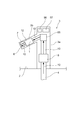
- FIG. 1 is a schematic view for illustrating an automatic faucet device (hereinafter also simply referred to as an automatic faucet device) provided with a faucet generator according to an embodiment of the present invention.
- FIG. 2 is a schematic cross-sectional view of an automatic faucet device provided with a faucet generator according to an embodiment of the present invention.
- the arrow in a figure represents the direction of flowing water.
- the automatic faucet device 3 is attached to, for example, a wash basin 2 or the like.
- the automatic water faucet device 3 is connected to an inflow port 5 such as tap water via a pipe 4.
- the automatic water faucet device 3 includes a cylindrical main body 3a and a water discharge portion 3b that is provided on an upper portion of the main body 3a and extends in a radially outward direction of the main body 3a.
- a water discharge port 6 is formed at the tip of the water discharge unit 3 b, and a sensor 7 is built in the vicinity of the water discharge port 6.
- a water supply passage 10 is formed that guides the water supplied from the inlet 5 and flowing through the pipe 4 to the water outlet 6.
- a solenoid valve 8 for opening and closing the water supply flow path 10 is built in the main body 3a, and a constant flow valve 55 for limiting the amount of water discharge is built on the downstream side of the solenoid valve 8.
- a pressure reducing valve or a pressure regulating valve (not shown) for reducing the pressure when the original pressure of water supply or the like is too higher than the working pressure is built in upstream of the electromagnetic valve 8. It should be noted that the constant flow valve 55, the pressure reducing valve, and the pressure regulating valve may be appropriately provided as necessary.
- the faucet generator 1 is provided inside the water discharger 3b downstream of the constant flow valve 55. Inside the main body 3a, a charger 56 for charging the electric power generated by the faucet generator 1 and a controller 57 for controlling the driving of the sensor 7 and the opening and closing of the electromagnetic valve 8 are provided. Since the faucet generator 1 is disposed on the downstream side of the solenoid valve 8 and the constant flow valve 55, the water supply source pressure (primary pressure) does not directly act on the faucet generator 1. Absent. Therefore, the faucet generator 1 is not required to have such a high pressure resistance, and such an arrangement is advantageous in terms of reliability and cost.
- the charger 56 and the control unit 57 are connected via a wiring (not shown). And the charger 56 and the control part 57 are the upper part of the main body 3a, Comprising: It arrange
- the coil 27 (see FIG. 4) provided in the faucet generator 1 and the control unit 57 are connected via a wiring (not shown), and the output (electric power) of the coil 27 is connected to the charger via the control unit 57. 56 to be sent.
- the automatic faucet device 3 is preferably used in a living space. Examples of the purpose of use include a kitchen faucet device, a living-dining faucet device, a shower faucet device, a toilet faucet device, and a toilet faucet device. Further, the faucet generator 1 according to the present embodiment is not limited to the automatic faucet device 3 using a human body sensor, for example, a one-touch faucet device by turning on / off a manual switch, The present invention can also be applied to a fixed water faucet device that stops water, a timer faucet device that stops water when a set time has elapsed, and the like. The generated electric power can also be used, for example, for light-up, generation of electrolyzed functional water such as alkali ion water or silver ion-containing water, flow rate display (metering), temperature display, voice guidance, and the like.
- a human body sensor for example, a one-touch faucet device by turning on / off a manual switch
- the present invention can also be applied to a fixed water faucet device that stops water,
- the discharge flow rate is set to, for example, 100 liters per minute or less, desirably 30 liters per minute or less. In particular, in a toilet faucet device, it is desirable to set it to 5 liters per minute or less. Further, when the discharge flow rate is relatively high as in the toilet faucet device, the water flow flowing from the water supply pipe to the faucet generator 1 is branched, and the flow rate flowing through the faucet generator 1 is 30 minutes per minute. It is desirable to adjust to liters or less. This is because if the flow rate is high and all the water flow from the water supply pipe is flowed to the faucet generator 1, the rotating speed of the rotor blade part becomes too large, which may increase noise and shaft wear. is there.
- the water supply pressure of the water pipe to which the faucet device is attached may be a low water pressure of about 50 kPa (kilopascal) in Japan, for example.
- the faucet generator 1 is provided outside the faucet fitting (the main body 3a and the water discharge part 3b) of the faucet device 3, electrical wiring work may be required when the faucet device 3 is installed. In addition, the installation location of the faucet generator 1 may be separately required. Therefore, it is preferable to provide the faucet generator 1 inside the faucet fitting of the faucet device 3. However, since there has been a tendency to adopt a slender design for the faucet fitting of the faucet device 3 in recent years, the faucet generator 1 incorporated therein needs to be further compact and high performance. It is coming.
- FIG. 3 is a schematic cross-sectional view for illustrating the faucet generator according to the embodiment of the present invention.
- the arrow in a figure represents the direction of flowing water.
- FIG. 4 is a schematic exploded view of the faucet generator according to the embodiment of the present invention.
- FIG. 5 is a cross-sectional view taken along the line AA in FIG. 6 is a cross-sectional view taken along line BB in FIG.
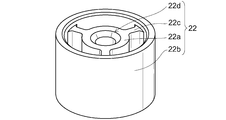
- FIG. 7 is a schematic perspective view for illustrating the bearing portion.
- the faucet generator 1 is mainly provided with a cylinder portion 11, a nozzle portion 12, a rotor 13, a magnet 14, a sealing portion 15, a stator 16, and a stator case 17.
- the cylindrical portion 11 has a stepped shape having a large diameter portion 11a, a medium diameter portion 11b, and a small diameter portion 11c.
- the cylinder part 11 has a water supply inflow port and a water supply outflow port, and the water supply flow path is formed in the inside.
- a sealing portion 15, a nozzle portion 12, a rotor 13, and a magnet 14 are provided in this order from the upstream side.
- the blade 15 a of the moving blade 18 provided in the sealing portion 15, the nozzle 12, and the rotor 13 is provided inside the large-diameter portion 11 a, and the movement of the blade 18 provided in the rotor 13.
- the blade boss 18b and the magnet 14 are provided inside the medium diameter portion 11b.
- a bearing portion 22 that supports one end on the downstream side of the rotating shaft 19 is provided inside the small diameter portion 11c.
- the bearing portion 22 includes a shaft support portion 22 a that rotatably supports one end on the downstream side of the rotating shaft 19 and supports the downstream end portion of the rotor blade portion 18, and a shaft support portion.
- a coupling portion 22b provided in the radially outward direction of 22a and a rib 22c that couples the shaft support portion 22a and the coupling portion 22b provided in the water supply flow path are provided.
- a bearing recess 22d is provided at the center of the shaft support portion 22a so that one end of the rotating shaft 19 can be rotatably supported.
- the bearing portion 22 can be attached to the cylindrical portion 11 by press-fitting the coupling portion 22b into the stepped hole 11c1 provided inside the small diameter portion 11c.
- the ribs 22c are provided radially between the outer surface of the shaft support portion 22a and the inner surface of the coupling portion 22b. Between the rib 22c and the rib 22c, it is a hole penetrating in the axial direction of the bearing portion 22, so that water flowing in from the upstream side can flow out to the downstream side.
- the upstream end portion of the shaft support portion 22 a and the holding portion 21 come into contact with each other through the spacer 23. Therefore, the thrust force that pushes the rotor 13 downstream can be supported by the bearing portion 22. That is, the bearing part 22 supports the thrust force applied to the moving blade part 18 (rotor 13).
- the shaft support portion 22a does not necessarily support the downstream end portion of the moving blade portion 18, but the shaft support portion 22a further supports the downstream end portion of the moving blade portion 18. By doing so, the upstream end portion (planar portion) of the shaft support portion 22 a and the downstream end portion (planar portion) of the rotor blade portion 18 can be brought into contact with each other via the holding portion 21 and the spacer 23. Therefore, it is possible to further suppress dust from entering between the rotary shaft 19 and the sliding surface of the shaft support portion 22a.
- a pipe (not shown) is connected to the small diameter portion 11c and the sealing portion 15 so that the inside of the cylindrical portion 11 communicates with the water supply channel.
- the cylindrical portion 11 is disposed so that the central axis direction thereof is substantially parallel to the direction of running water.
- the cylindrical portion 11 is arranged with the small diameter portion 11c facing the downstream side and the large diameter portion 11a facing the upstream side.
- the sealing part 15 is provided at the water supply inlet of the cylinder part 11.
- a stepped hole is provided inside the sealing portion 15 so that the stepped hole communicates with the water supply channel.
- the opening at the upstream end of the large-diameter portion 11a is blocked by the sealing portion 15 via the O-ring 24 so as to be liquid-tight. Further, when the sealing portion 15 is fixed to the opening at the upstream end of the large diameter portion 11a, the position of the nozzle portion 12 in the axial direction is regulated by the sealing portion 15.
- the nozzle section 12 allows water flowing from a direction parallel to the rotation center axis to move from the radially outer direction of the moving blade blade section 18a to the moving blade blade section 18a in a plane substantially perpendicular to the rotation center axis. It has the some injection hole 12a which ejects toward.
- a shaft support portion 12 b that protrudes toward the upstream side is provided at the central portion of the nozzle portion 12.
- a plurality of projecting portions 12 c projecting toward the upstream side and projecting radially outward are provided at the peripheral portion of the nozzle portion 12.
- a bearing hole 12d that rotatably supports one end of the rotary shaft 19 is provided in the shaft support portion 12b. Details regarding the nozzle unit 12 will be described later.
- the rotor 13 is provided with a lid portion 20, a moving blade portion 18, a rotating shaft 19, and a holding portion 21.
- a lid portion that rotates integrally with the rotor blade blade portion 18a in order to prevent water injected from the injection hole 12a from escaping upstream from the rotor blade blade portion 18a. 20 is provided.
- the lid portion 20 has a disk shape, and a shaft holding portion 20a that protrudes toward the upstream side and the downstream side is provided at the center portion thereof.
- a press-fitting hole for press-fitting the rotary shaft 19 is provided in the central portion of the shaft holding portion 20a.
- the downstream portion of the shaft holding portion 20a is press-fitted into a stepped portion provided at the upstream end portion of the insertion portion 18f.
- the moving blade portion 18 includes a moving blade portion 18a, a moving blade boss portion 18b, and a holding plate portion 18c, and is provided in the water supply flow path. That is, the moving blade portion 18 (the moving blade portion 18a) has a rotation center axis substantially parallel to the water supply flow path, and is provided in the water supply flow path so as to be rotatable around the rotation center axis.
- the moving blade portion 18a is configured by a curve, and is curved in such a direction that the tip approaches toward the center of the moving blade portion 18.
- the number of blade blades 18a is a value different from an integral multiple of the number of injection holes 12a. For example, in the example illustrated in FIG.
- the number of the blade blade portions 18a is 11 and the number of the injection holes 12a is three. If the number of moving blade blades 18a is different from an integer multiple of the number of injection holes 12a, the timing at which the water discharged from the injection holes 12a collides with the vicinity of the outer peripheral edge of each moving blade blade 18a is shifted. Therefore, the vibration and noise generation of the rotor blade portion 18 can be suppressed.
- a holding plate portion 18c that holds the moving blade blade portion 18a is provided at the downstream end of the moving blade blade portion 18a. That is, the holding plate portion 18c is provided at the downstream end portion of the moving blade blade portion 18a and rotates integrally with the moving blade blade portion 18a. A space defined by the blade blade 18a, the holding plate 18c, and the lid 20 becomes the blade flow path 18h.
- a hole 18d is provided in the vicinity of the center of the holding plate 18c for allowing water that has flowed through the blade flow path 18h to flow downstream.
- the hole 18d of the holding plate portion 18c is provided in the vicinity of the center of the holding plate portion 18c, and a flow path (hole) for flowing the water jetted toward the hole 18d and the blade blade 18a to the downstream side.
- a flow path for flowing the water jetted toward the hole 18d and the blade blade 18a to the downstream side.
- a moving blade boss 18b is provided on the downstream side of the moving blade 18a.
- a hole 18e penetrating in the axial direction is provided inside the blade boss 18b, and one end of the hole 18e communicates with the hole 18d.
- the hole 18e serves as a flow path for flowing the water flowing through the moving blade flow path 18h to the downstream side.
- An insertion portion 18f through which the rotary shaft 19 is inserted is provided at the central portion of the moving blade boss portion 18b.
- a stepped portion for press-fitting the shaft holding portion 20a of the lid portion 20 is provided at the upstream end portion of the insertion portion 18f. Further, a stepped portion for press-fitting the boss portion 21b of the holding portion 21 is provided at the downstream end portion of the insertion portion 18f.
- the rotary shaft 19 has a cylindrical shape and is provided substantially parallel to the water supply flow path. Further, the rotating shaft 19 is provided such that one end protrudes in the upstream direction from the moving blade blade portion 18a and the other end protrudes in the downstream direction from the moving blade boss portion 18b. One end on the upstream side of the rotary shaft 19 is rotatably held by the shaft support portion 12b, and one end on the downstream side is rotatably held by the bearing portion 22.
- the holding part 21 has a flange part 21a and a boss part 21b, and a press-fitting hole for press-fitting the rotary shaft 19 is provided at the center part thereof.
- the boss portion 21b is press-fitted into a stepped portion provided at the downstream end of the insertion portion 18f.
- the rotary shaft 19 inserted through the insertion portion 18f of the rotor blade portion 18 is press-fitted into the press-fitting hole of the lid portion 20 and the press-fitting hole of the holding portion 21, and the downstream portion of the shaft holding portion 20a of the lid portion 20 and the holding portion
- the boss portion 21b of 21 into the stepped portion of the insertion portion 18f the moving blade portion 18, the rotary shaft 19, the lid portion 20, and the holding portion 21 are integrated.
- the lid portion 20, the moving blade portion 18, the rotating shaft 19, and the holding portion 21 are integrated as the rotor 13, and the integrated rotor 13 rotates integrally around the rotating shaft 19.
- a cylindrical magnet 14 is provided on the outer peripheral surface (end surface in the radial direction) of the rotor blade boss 18b.
- the magnet 14 can rotate integrally with the moving blade portion 18.
- N poles and S poles are alternately magnetized along the circumferential direction.
- a stator 16 is provided on the outer side of the small diameter portion 11 c of the cylindrical portion 11.
- the stator 16 is provided so as to face the axial end surface of the magnet 14. Therefore, the radial dimension can be reduced as compared with the case where the stator 16 is disposed opposite to the outer diameter direction of the magnet 14. Further, since the stator 16 is not disposed in the radially outward direction of the moving blade portion 18, the radial dimension of the moving blade portion 18 can be increased, and the amount of power generation can be increased.
- the stator 16 includes a first yoke 25, a second yoke 26, an inductor 25 a and an inductor 25 b that are connected to the first yoke 25, and an inductor that is connected to the second yoke 26, all of which are made of a soft magnetic material (for example, rolled steel).
- the coil 27 in which the conducting wire is wound in an annular shape is surrounded by the first yoke 25 and the second yoke 26 at the inner peripheral surface portion and the outer peripheral surface portion.
- the coil 27 generates an electromotive force by the rotation of the magnet 14.
- the first yoke 25 has a substantially annular shape and is disposed so as to surround the inner peripheral surface portion of the coil 27, and a plurality of inductors 25a are integrally provided at one axial end portion thereof in the radially outward direction. ing.
- the inductor 25 a is provided so as to be substantially perpendicular to the first yoke 25.
- the inductors 25 a are arranged at equal intervals along the circumferential direction of the coil 27.
- One end of the inductor 25a further extends in the axial direction of the coil 27 to form an inductor 25b.
- the second yoke 26 has a substantially annular shape and is disposed so as to surround the outer peripheral surface portion of the coil 27, and a plurality of inductors 26a are integrally provided at one axial end portion thereof in the axial direction.
- the inductors 26 a are arranged at equal intervals along the circumferential direction of the coil 27 and are arranged between the inductors 25 b of the first yoke 25. That is, there are provided a plurality of inductors 25b and 26a that exchange portions of magnets that are spaced apart from each other and have portions that oppose each other in the radial direction of the magnet 14.
- the inductors 25b and 26a are provided immediately above a portion (second yoke 26) disposed so as to surround the outer peripheral surface portion of the coil 27, and the distances from the center of the coil 27 to the inductors 25b and 26a are substantially the same. ing.
- a stepped hole is provided in the stator case 17 so as to penetrate the axial direction.
- the stator 16 is inserted into a hole having a large diameter, and the small diameter portion 11c is inserted into a hole having a small diameter.
- the stator case 17 is attached to the cylinder part 11 by hold
- water flowing from a direction parallel to the rotation center axis is allowed to flow in a plane substantially perpendicular to the rotation center axis.
- wear of the bearing portion or the like becomes a problem. That is, if water is ejected from the radially outward direction of the moving blade blade portion 18a toward the moving blade blade portion 18a, the water flow around the axis increases.
- the shaft is fixed and the moving blade portion rotates around the fixed shaft, water flows in a gap provided between the fixed shaft and the moving blade portion. For this reason, there is a risk that dust such as rust contained in water enters the gap between the shaft and the moving blade portion, resulting in wear and backlash due to wear and the like, resulting in reduced power generation efficiency.
- the moving blade portion 18 and the rotating shaft 19 are integrated, and the integrated moving blade portion 18 and rotating shaft 19 rotate integrally around the rotating shaft 19. It is like that. Therefore, water does not flow between the rotating shaft 19 and the moving blade portion 18, and the rotating shaft 19 and the moving blade portion 18 do not move relative to each other. There is nothing.
- the rotating shaft 19 rotates when the rotor blade portion 18 and the rotating shaft 19 are integrated, the rotating shaft 19 and the members that support the rotating shaft 19 (the shaft support portion 12b and the bearing portion 22) are connected. It is necessary to provide a gap between them. Therefore, in such a case, wear in the rotating shaft 19 and the members (the shaft support portion 12b and the bearing portion 22) that support it becomes a problem.
- a rib 22 c is provided in the bearing portion 22, and a water supply channel is formed between the rib 22 c and the rib 22 c. Therefore, flowing water is blocked by the rib 22c, and the water pressure increases in the vicinity of the upstream end portion of the rib 22c. If the water pressure rises in the vicinity of the upstream end of the rib 22c, dust such as rust may be pushed in between the rotating shaft 19 and the bearing portion 22 together with water. That is, since the rib 22c narrows the water supply channel, the water flowing through the water supply channel can easily flow between the rotating shaft 19 and the bearing portion 22. For this reason, in the present embodiment, an intrusion preventing means for preventing dust such as rust from entering between the rotary shaft 19 and the sliding surface of the shaft support portion 22a using water is provided. .
- the intrusion prevention means in the present invention does not simply prevent water from entering between the rotating shaft 19 and the sliding surface of the shaft support portion 22a, but between the rotating shaft 19 and the sliding surface of the shaft support portion 22a. It is based on a completely new technical idea of preventing a large amount of water from flowing in using the water already in between.
- Examples of the intrusion prevention means include those in which water is filled between the rotating shaft 19 and the sliding surface of the shaft support portion 22a. That is, by filling the space between the rotating shaft 19 and the sliding surface of the shaft support portion 22a, the passage between the rotating shaft 19 and the sliding surface of the shaft support portion 22a does not become a flow path. Water is prevented from flowing in and passing through. This is not to prevent water from entering between the rotating shaft 19 and the sliding surface of the shaft support portion 22a, but is filled between the rotating shaft 19 and the sliding surface of the shaft support portion 22a. Based on a completely new technological idea of not allowing water to flow (no flow path), it prevents rust and other dust from entering.
- a device formed by sealing the downstream side of the shaft support portion 22a (a device that seals the downstream end portion of the hole supporting the rotating shaft 19) can be exemplified.
- the downstream side of the shaft support portion 22a is sealed so that the downstream side of the shaft support portion 22a is sealed so that there is no flow path between the rotating shaft 19 and the sliding surface of the shaft support portion 22a. That's fine.
- the downstream end of the support portion 22a can be sealed as illustrated below.
- a hole for supporting the rotating shaft 19 provided in the bearing portion 22 is a bottomed bearing concave portion 22d.
- the operation of the bearing recess 22d as the intrusion preventing means will be described.
- the water supply flow path of the faucet generator 1 is in a state where only air is contained.
- the water that has flowed into the faucet generator 1 rotates the rotor blade 18 and then flows downstream along the axial direction.
- the water supply flow path is narrowed by the rib 22c provided in the bearing portion 22, so that water enters between the rotating shaft 19 and the bearing recess 22d.
- the water that is about to enter newly does not enter between the rotating shaft 19 and the bearing recess 22d, but flows through the water supply channel downstream. That is, since the passage between the rotating shaft 19 and the bearing recess 22d does not serve as a flow path, new water can be prevented from entering.
- the simple configuration of sealing the downstream end portion of the hole that supports the rotating shaft 19 makes it possible to prevent entry of dust using water. For this reason, it is possible to prevent a problem of deteriorating the power generation performance such as wear of the bearing portion, and to realize a highly efficient and compact water faucet generator.
- the water film 32 is generated by the centrifugal force generated by the rotation of the moving blade portion 18 so that dust enters between the rotating shaft 19 and the sliding surface of the shaft support portion 22a. What can be prevented can be exemplified.
- FIG. 8 is a schematic partial cross-sectional view for illustrating the water film generation unit 29.
- the holding part 30 has a flange part 30a, a boss part 30b, and a first water film holding part 30c, and a press-fitting hole for press-fitting the rotary shaft 19 is provided in the central part thereof.
- the boss portion 30b is provided so as to protrude from the flange portion 30a toward the upstream side, and is press-fitted into a stepped portion provided at the downstream end portion of the insertion portion 18f.
- the first water film holding part 30c is provided so as to protrude from the flange part 30a toward the downstream side.
- the outer peripheral surface of the first water film holding part 30c is provided so as to protrude in the radially outward direction from the flange part 30a.
- a concave portion 30d is provided in the first water film holding portion 30c.
- the bearing portion 31 includes a support portion 31a that supports one end of the rotating shaft 19, a cylindrical coupling portion 31b provided concentrically with the support portion 31a, and a support portion 31a.
- a rib 31c that connects the coupling portion 31b is provided.
- maintenance part 31e which protrudes toward an upstream from the upstream edge part of the support part 31a is provided.
- a bearing recess 31d is provided at the center of the support portion 31a so that one end of the rotary shaft 19 can be rotatably supported.
- the bearing part 31 can be attached to the cylinder part 11 by press-fitting the coupling part 31b into the stepped hole 11c1 provided inside the small diameter part 11c.
- the ribs 31c are provided radially between the outer surface of the support portion 31a and the inner surface of the coupling portion 31b. Between the rib 31c and the rib 31c, it is a hole penetrating in the axial direction of the bearing portion 31, so that water flowing in from the upstream side can flow out to the downstream side.
- the upstream end portion of the second water film holding portion 31 e and the holding portion 30 come into contact with each other through the spacer 23. Therefore, the thrust force that pushes the rotor 13 downstream can be supported by the bearing portion 31. That is, the bearing part 31 supports the thrust force applied to the moving blade part 18 (rotor 13).
- the outer surface dimension of the second water film holding part 31e is smaller than the inner surface dimension of the recessed part 30d provided in the first water film holding part 30c, and the outer surface dimension of the second water film holding part 31e and the recessed part 30d. A gap is provided between the inner surface of each of the members.
- the inner surface of the recess 30d provided in the first water film holding part 30c and the outer surface of the second water film holding part 31e face each other with a gap.
- the water film 32 is produced
- the water that has flowed into the faucet generator 1 rotates the rotor blade 18 and then flows downstream along the axial direction.
- the water supply flow path is narrowed by the rib 31c provided in the bearing portion 31, so that water enters the gap between the inner surface of the recess 30d and the outer surface of the second water film holding portion 31e. become.
- the water that has entered is prevented from flowing out of the recess 30d, so that water can flow between the inner surface of the recess 30d and the outer surface of the second water film holding portion 31e. It will be filled.
- water is also filled in the gap between the bearing recess 31d provided at the center of the support portion 31a and the rotary shaft 19.
- the passage between the bearing recess 31d provided at the center of the support portion 31a and the rotating shaft 19 does not serve as a flow path, thereby preventing intrusion and accumulation of dust.
- the water film generation unit 29 can prevent intrusion of dust using water. For this reason, it is possible to prevent a problem of deteriorating the power generation performance such as wear of the bearing portion, and to realize a highly efficient and compact water faucet generator.
- the nozzle part 12 is a member for injecting water to the rotor blade blade part 18a. For this reason, if injection is performed in a state where the center of the injection hole 12a and the moving blade blade portion 18a or the injection hole 12a and the flow path are shifted, an appropriate force is not applied to the moving blade blade portion 18a and the power generation efficiency is reduced. There is a risk that. Therefore, the nozzle portion 12 includes a plurality of protruding portions 12 c that protrude in the radially outward direction and come into contact with the inner wall of the cylindrical portion 11.
- the upstream end face of the protruding portion 12 is further protruded upstream. That is, the nozzle portion 12 includes a plurality of protruding portions 12c protruding toward the upstream side and protruding in the radially outward direction at the peripheral portion.
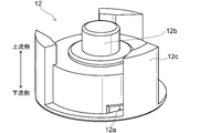
- FIG. 9 is a schematic perspective view for illustrating the nozzle portion.
- FIG. 10 is a cross-sectional view taken along the line CC in FIG.
- the peripheral part of the nozzle part 12 is provided with a plurality of projecting parts 12c that project toward the upstream side and project in the radially outward direction.
- the upstream end surface of the protruding portion 12 c comes into contact with the sealing portion 15. Therefore, when the sealing portion 15 is fixed to the opening at the upstream end of the large diameter portion 11a, the axial position of the nozzle portion 12 is regulated by the sealing portion 15.
- the end surface (outer peripheral surface) in the radially outward direction of the projecting portion 12c comes into contact with the inner wall of the large diameter portion 11a.
- the nozzle portion 12 includes a plurality of protruding portions 12 c that protrude in the radially outward direction and come into contact with the inner wall of the cylindrical portion 11. Therefore, when the nozzle portion 12 is attached to the inside of the large diameter portion 11a, the central axis of the large diameter portion 11a and the central axis of the nozzle portion 12 are matched.
- the radially outer end face (outer peripheral surface) of the protruding part 12c can be brought into contact with the inner wall of the large diameter part 11a.
- the position of the nozzle part 12 relative to the faucet generator 1 (cylinder part 11) can be defined reliably.
- positioning (center axis alignment) of the nozzle portion 12 with respect to the faucet generator 1 can be performed reliably. Therefore, it is possible to solve the problem that the power generation efficiency is lowered by attaching the nozzle portion 12 in a shifted state. As a result, high power generation efficiency can be maintained in the faucet generator 1 having the compactness and high performance of the axial flow generator.
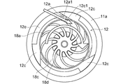
- the protruding portion 12c is arranged at a position shifted from the injection hole 12a toward the rotating direction of the rotor blade blade portion 18a.
- the protrusion 12c is arranged at a position shifted from the injection hole 12a toward the rotating direction of the rotor blade blade 18a.
- the side wall 12a1 on the rotation direction side of the moving blade blade portion 18a of the injection hole 12a and the side wall 12c1 on the opposite side to the rotation direction of the moving blade blade portion 18a of the protruding portion 12c Are arranged so as to be flush with each other.
- the water flowing through the sealing portion 15 hits the upstream end surface of the nozzle portion 12 and is guided in the radially outward direction of the nozzle portion 12.
- induced to the radial direction of the nozzle part 12 flows into the groove part 12e formed between the protrusion parts 12c, and is guided toward the injection hole 12a. That is, the groove part 12e formed between the protrusion parts 12c functions as a groove for guiding water to the injection hole 12a.
- the water flowing in the groove 12e hits the side wall 12c1 opposite to the rotation direction of the rotor blade portion 18a of the protrusion 12c and enters the injection hole 12a. That is, the water guided toward the injection hole 12a functions as a wall that stops passage of water without entering the injection hole 12a.
- the protrusion 12c is a groove that guides water to the injection hole 12a between the protrusions, and the protrusion 12c is a wall that holds water that is about to pass without entering the injection hole 12a. It arrange
- the protrusion 12c is arranged at a position shifted from the injection hole 12a toward the rotation direction of the rotor blade blade 18a, so that the flow of water flowing into the injection hole 12a is obstructed. Can be suppressed as much as possible. Moreover, by setting it as such an arrangement
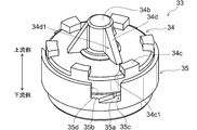
- FIG. 11 is a schematic perspective view for illustrating a nozzle portion according to another embodiment.
- the nozzle part 33 illustrated in FIG. 11 is configured by dividing the nozzle part 12 described above into two parts. If the injection hole can be accurately formed, the performance of the faucet generator 1 can be improved. In this case, if the nozzle portion having the injection hole is integrally formed, the injection hole can be formed with high accuracy. However, since the injection hole is provided on the side surface of the nozzle portion, there is a possibility that die cutting or molding becomes difficult. In this case, the nozzle part can be divided into two parts, and the nozzle part having the injection holes can be formed by assembling the divided elements.
- the opening area of the injection hole may change after or during assembly.
- an element divided by water pressure or the like will wobble and the opening area of the injection hole may change.
- a plurality of positions on the periphery of the divided elements may be fixed with an adhesive or the like.
- the opening area of the injection hole is changed by the protruding adhesive.
- appropriate ejection cannot be performed and there exists a possibility that electric power generation efficiency etc. may fall.
- the nozzle portion 33 is provided with a stepped hole 35b that opens in the upstream end surface in the central portion and a plurality of nozzle grooves 35a that open in the upstream end surface in the peripheral portion.
- 1 nozzle housing part 35 and a second nozzle housing part 34 fitted so as to close the opening of the stepped hole 35b of the first nozzle housing part 35.
- the second nozzle housing part 34 is fitted so as to close the opening of the stepped hole 35b of the first nozzle housing part 35, the nozzle groove 35a of the first nozzle housing part 35 and the first groove
- An injection hole 35 c is formed by the two nozzle housing portions 34.
- the nozzle portion 33 is divided and the nozzle groove 35 a of the first nozzle housing portion 35 and the second nozzle housing portion 34 form the injection hole 35 c. Further, the upstream end face of the projecting portion 34c is projected upstream, and the sealing portion 15 regulates the axial positions of the second nozzle housing portion 34 and the first nozzle housing portion 35. Yes.
- the nozzle portion 33 is provided with a second nozzle housing portion 34 and a first nozzle housing portion 35.
- a shaft support portion 34 b that protrudes toward the upstream side is provided at the central portion of the second nozzle housing portion 34.
- a plurality of protruding portions 34 c that protrude toward the upstream side are provided at the peripheral portion of the second nozzle housing portion 34 in order to restrict the position of the nozzle portion 33 in the axial direction.
- a bearing hole portion that rotatably supports one end of the rotating shaft 19 is provided in the shaft support portion 34b. Further, the upstream end face of the protruding portion 34 c comes into contact with the sealing portion 15.
- a stepped hole 35 b is provided inside the first nozzle housing part 35.
- a plurality of nozzle grooves 35 a penetrating through the stepped holes 35 b are provided on the peripheral surface of the first nozzle housing portion 35.
- the second nozzle housing part 34 is fixed so as to close the opening at the upstream end of the first nozzle housing part 35 by restricting the axial position of the protruding part 34 c by the sealing part 15. It has become so. Further, when the second nozzle housing part 34 is fixed to the first nozzle housing part 35, the second nozzle housing part 34 and the nozzle groove 35a form an injection hole 35c. ing.
- the blade blade portion of the moving blade portion 18 is provided in the space formed inside the first nozzle housing portion 35 by fixing the second nozzle housing portion 34 to the first nozzle housing portion 35. 18a is provided. The injection hole 35 c is opened toward the moving blade blade 18 a housed in a space formed inside the first nozzle casing 35.
- the end surface (outer peripheral surface) in the radially outward direction of the first nozzle housing portion 35 comes into contact with the inner wall of the large diameter portion 11a. Therefore, when the nozzle part 33 is attached inside the large diameter part 11a, the central axis of the large diameter part 11a and the central axis of the nozzle part 33 are matched. In this way, when the nozzle portion 33 is attached to the faucet generator 1 (large diameter portion 11a), the radially outer end surface (outer peripheral surface) of the first nozzle housing portion 35 is formed on the inner wall of the large diameter portion 11a. Since it can be made to contact
- the protrusion part 34c is arrange
- a groove portion 35 d communicating with the injection hole 35 c is provided on the end surface (outer peripheral surface) in the radially outward direction of the first nozzle housing portion 35.
- the groove 35d is provided so as to be positioned between the protrusion 34c and the protrusion 34c.
- a space between the groove portions 35d along the circumferential direction corresponds to a plurality of protruding portions 12c protruding in the radially outward direction illustrated in FIG. 9 and contacting the inner wall of the cylindrical portion 11.
- a flow dividing portion 34 d is provided on the upstream surface of the second nozzle housing portion 34.
- the nozzle portion 33 allows water flowing from a direction parallel to the rotation center axis to move from the radially outer direction of the moving blade blade portion 18a to the moving blade blade portion 18a in a plane substantially perpendicular to the rotation center axis. It is necessary to change the flow of water so that it can be jetted out. In order to obtain higher power generation efficiency, it is necessary to appropriately guide water to the portion that converts the flow of water, that is, the injection hole.
- the flow dividing portion 34d for diverting the flowing water to the groove portion 35d between the projecting portions 34c is provided on the upstream surface of the nozzle portion 33 (the upstream surface of the second nozzle housing portion 34). I am trying to provide it.
- the water that has flowed toward the nozzle portion 33 is diverted by the diversion portion 34d and then guided to the injection hole.
- a surface 34d1 in a direction parallel to the rotation center axis of the flow dividing portion 34d and a surface 34c1 in a direction parallel to the rotation center axis of the protruding portion 34c are substantially in a straight line.
- the water diverted by the diversion part 34d is guided to the groove part 35d without being obstructed by the projecting part 34c and guided. It is only necessary that the surface 34d1 and the surface 34c1 overlap so that water can be ejected from the ejection hole 35c.
- the protrusion part 34c mentioned above is a member (member which regulates the position of the axial direction of the nozzle part 33) for the backlash etc. of the nozzle part 33, since it is a projection shape, it is between protrusion parts 34c. Water can flow between them.
- the nozzle portion 33 is divided into the second nozzle housing portion 34 and the first nozzle housing portion 35, die cutting and molding can be facilitated. Further, by inserting the second nozzle housing portion 34 into the stepped hole 35b of the first nozzle housing portion 35, the second nozzle housing portion 34 and the nozzle groove 35a form an injection hole 35c. It has become so. Therefore, the injection hole 35c can be formed with high accuracy.
- the second nozzle housing part 34 is in contact with the first nozzle housing part 35 via the protruding part 34 c by the sealing part 15. Therefore, since no adhesive or the like is used, there is no possibility that the opening area of the injection hole 35c changes.
- the second nozzle casing 34 and the first nozzle casing 35 are in contact with each other, the second nozzle casing 34 and the first nozzle casing 35 are deformed by water pressure or the like. There is no fear. Therefore, there is no possibility that the opening area of the injection hole 35c changes during power generation, and stable power generation can be performed.
- water pressure is applied by the water flow, the sealing portion 15 is lifted and the protruding portion 34c that is in contact with the sealing portion 15 is separated. In this case, the second nozzle housing portion 34 is moved to the first by the water pressure. Therefore, the change in the opening area of the injection hole 35c can be suppressed.
- the second nozzle housing part 34 is fitted into the stepped hole 35b of the first nozzle housing part 35, the second nozzle housing part 34 and the first nozzle housing part The positional deviation in the radial direction with respect to 35 can be suppressed. In addition, it is possible to suppress variation in the opening area of the injection hole 35c due to the radial displacement between the second nozzle housing portion 34 and the first nozzle housing portion 35.
- the flow dividing portion 34d is provided on the upstream surface of the second nozzle housing portion 34, it is possible to guide the water that has flowed to the injection hole 35c after being branched. For this reason, there is a problem such that water is not guided and spray is not performed from the spray holes 35c, the amount of spray from each of the spray holes 35c is uneven, or hydraulic energy is not transmitted skillfully to the rotor blade blade 18a. Can be resolved. As a result, more efficient power generation can be performed.
- the surface 34d1 in a direction parallel to the rotation center axis of the flow dividing portion 34d and the surface 34c1 in a direction parallel to the rotation center axis of the protruding portion 34c are substantially in a straight line. Therefore, it is possible to guide water to each injection hole 35c without causing unnecessary energy loss or stagnation until it is jetted toward the blade blade 18a after being divided. In addition, it is possible to suppress a deviation in the amount of water to be injected. As a result, highly efficient power generation can be realized.
- An end surface (outer peripheral surface) in the radially outward direction of the first nozzle housing portion 35 is in contact with the inner wall of the large diameter portion 11a. Therefore, when the nozzle part 33 is attached inside the large diameter part 11a, the central axis of the large diameter part 11a and the central axis of the nozzle part 33 are matched. In this way, when the nozzle portion 33 is attached to the faucet generator 1 (large diameter portion 11a), the radially outer end surface (outer peripheral surface) of the first nozzle housing portion 35 is formed on the inner wall of the large diameter portion 11a.
- the position of the nozzle part 33 with respect to the faucet generator 1 (cylinder part 11) can be prescribed
- the protrusion part 34c and the groove part 35d are arrange
- the integrated configuration The flow dividing portion 34d can be provided on the upstream surface of the nozzle portion 12 (in the case of FIG. 9).
- the arrangement relationship between the flow dividing portion 34d and the protruding portion 12c can be the same as the arrangement relationship between the flow dividing portion 34d and the protruding portion 34c described above.
- the lid 20 will be further described.
- the water that is ejected from the injection hole 12a and flows in the radial direction of the moving blade blade portion 18a is the inner wall on the upstream side of the nozzle portion 12.
- stagnation may occur due to entering a gap between the (ceiling portion) and the blade portion 18a.
- a water flow that disturbs the water flow that transmits hydraulic power to the rotor blade blade 18a is generated.
- the power generation efficiency may be reduced.
- the inner wall (ceiling part) on the upstream side of the nozzle part 12 is fixed with respect to the cylinder part 11, the inner wall on the upstream side of the nozzle part 12 (when the rotor blade part 18a is rotating) ( The ceiling part) is stationary. And when the water which hits the blade part 18a tried to escape upstream, if it collides with the upstream inner wall (ceiling part) of the nozzle part 12 which is a stationary object, hydraulic energy will be deprived excessively. It will be. In this case, the rotor blade blade portion 18a is continuously rotated by the water from which the hydraulic energy is excessively deprived, so that the rotation efficiency is lowered, and consequently the power generation efficiency is lowered.
- the lid portion 20 is provided so as to cover the upstream side of the rotor blade blade portion 18a. If it does in this way, it can prevent that the water ejected from the injection hole 12a enters into the clearance gap between the inner wall (ceiling part) of the upstream of the nozzle part 12, and the moving blade blade
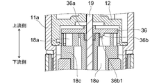
- FIG. 12 is a schematic diagram for illustrating a lid according to another embodiment.
- the lid portion 36 has a disk shape, and a shaft holding portion 36a that protrudes toward the upstream side and the downstream side is provided at the center portion thereof.
- a hole for inserting the rotary shaft 19 is provided in the central portion of the shaft holding portion 36a.
- the downstream portion of the shaft holding portion 36a is press-fitted into a stepped portion provided at the upstream end portion of the insertion portion 18f.
- the lid portion 36 includes an annular direction changing portion 36 b that protrudes toward the downstream side provided on the downstream surface of the lid portion 36.
- the direction change part 36b equips the downstream end part with the surface 36b1 for guiding the flowing water to the downstream side.
- the surface 36b1 illustrated in FIG. 12 is a tapered surface, any surface that can guide the flowing water to the downstream side may be used. For example, it can be “R-plane”.
- the water ejected from the injection hole 12a flows in the radial direction of the rotor blade blade 18a.
- the water after the hydraulic power is transmitted to the rotor blade blade 18a flow immediately downstream.
- the flow direction of water is changed to a direction substantially perpendicular to the rotation center axis, and is further guided in the radially inward direction of the rotor blade blade portion 18a by a second lid portion (holding plate portion 18c) described later.
- a second lid portion holding plate portion 18c
- annular direction changing portion 36b protruding toward the downstream side is provided on the downstream side surface of the lid portion 36.
- the surface 36b which changes so that the flow direction of the water which flows through the inside of the rotor blade flow path 18h may face a downstream is provided in the edge part of the direction conversion part 36b.
- the direction changing part 36b having such a surface 36b1 it is possible to smoothly flow the water after transmitting the hydraulic force to the rotor blade blade part 18a to the downstream side. Therefore, power generation efficiency can be improved. Moreover, since the direction changing part 36b is provided in the rotating cover part 36, there is a possibility that turbulent flow may occur if a plate-like one is provided. For this reason, in the present embodiment, the direction changing portion 36b is formed in an annular shape to suppress the occurrence of turbulent flow. In addition, since the lid portion 36 can also have a function of “changing the flow direction of the water flowing in the moving blade flow path 18 h to face the downstream side”, the “compact” can be achieved without adding unnecessary members. Can be realized.
- a second lid portion (holding plate portion 18c), which will be described later, guides water in the radially inward direction of the moving blade blade portion 18a, and the flow direction of water flowing in the moving blade flow passage 18h is directed to the downstream side. If the respective flows caused by the surface 36b1 to be converted to interfere with each other, there is a risk that the stagnation is caused by the flow of water and the power generation efficiency is lowered. Therefore, the second lid part (holding plate part 18c) and the direction changing part 36b (surface 36b1) are arranged so as not to overlap each other when viewed in the axial direction. In other words, the direction changing portion 36b is disposed so as not to overlap the second lid portion (holding plate portion 18c) when viewed in the axial direction. By doing so, the stagnation of the flow of water can be prevented, so that a decrease in power generation efficiency can be suppressed.
- a caulking portion that fixes and positions the rotating shaft 19 that rotates integrally with the moving blade portion 18 provided on the rotation center axis of the moving blade portion 18 is provided on the lid portion 36.
- the downstream portion of the shaft holding portion 36a can also be used as a caulking portion. That is, the lid portion 36 may have a caulking portion that fixes and positions the rotating shaft 19 that rotates integrally with the moving blade portion provided on the rotation center axis of the moving blade portion 18.
- a caulking portion can also be provided in the lid portion 20 described above.
- the rotating shaft 19 and the lid portion 36 can be securely fixed, so that the rotating shaft 19 and the rotor blade portion 18 rotate together and the rotation center axis does not shift. . Moreover, the power generation efficiency does not decrease. Furthermore, since the rotary shaft 19 is positioned at a suitable position with respect to the nozzle portion 12 and the flow path by the lid portion 36, higher power generation efficiency can be obtained. In addition, by combining these functions (fixing / positioning) with the lid portion 36, a “compact” configuration can be realized.
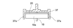
- FIG. 13 is a schematic diagram for illustrating the injection holes provided to be inclined.
- the nozzle portion 37 is provided with an injection hole 37 a that is inclined so that the injection direction with respect to the rotor blade portion 18 a faces the upstream side.
- Water injected from the injection hole 37a provided so as to be inclined so that the injection direction with respect to the moving blade blade 18a faces the upstream side is along the lid portion 20 in the radially inward direction of the moving blade blade 18a. Flowing. Therefore, since it is suppressed that it flows out immediately downstream, hydraulic power can fully be transmitted to the moving blade blade part 18a. As a result, power generation efficiency can be improved.
- the holding plate portion 18c will be further described.
- the lid portion 20 when the lid portion 20 is provided on the moving blade portion 18, the upstream side of the moving blade blade portion 18 a is covered by the lid portion 20, so that water tends to flow downstream. For this reason, after water hits the rotor blade blade 18a, the water may flow immediately downstream. If it becomes like this, hydraulic power cannot fully be transmitted to the moving blade blade
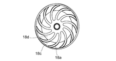
- FIG. 14 is a schematic view for illustrating the holding plate portion.
- a holding plate portion 18c that holds the moving blade blade portion 18a is provided at the downstream end of the moving blade blade portion 18a.
- the holding plate portion 18c is provided in the vicinity of the outer periphery of the rotor blade blade portion 18a.
- the holding plate portion 18c holds the moving blade blade portion 18a and also serves as a bottom plate of the moving blade flow path 18h, that is, a lower lid portion (second lid portion). That is, the second lid portion (holding plate portion 18c) for guiding the water sprayed from the spray hole 12a toward the center of the blade portion 18 in the vicinity of the outer periphery of the downstream end portion of the blade portion 18a. Is provided.
- the second lid (holding plate 18c) is provided on the moving blade portion 18 similarly to the lid 20, the second lid (holding plate 18c), the lid 20 and the bucket blade portion. 18a can be rotated integrally. Therefore, even if the sprayed water hits the second lid part (holding plate part 18c) or the lid part 20, since these are relatively stationary, the hydraulic energy is not excessively deprived. In addition, since it is not necessary to separately provide a member that serves as a bottom plate of the blade flow path 18h, a “compact” configuration can be realized.
- the action of the lid part described above prevents water ejected from the injection hole 12a from entering the gap between the upstream inner wall (ceiling part) of the nozzle part 12 and the blade blade part 18a. Moreover, the water ejected from the injection hole 12a can pass through the moving blade channel 18h with a clean flow. Moreover, it can suppress that the quantity of the water which flows through the moving blade flow path 18h reduces.
- the magnet 14 fixed thereto is also rotated.
- the end surface (outer peripheral surface) in the outer diameter direction of the magnet 14 has the N pole and the S pole alternately magnetized along the circumferential direction (rotational direction).
- the polarities of the inductors 25a, 25b, and 26a facing the end surfaces (outer peripheral surfaces) in the direction and the first yoke 25 and the second yoke 26 connected to the inductors 25a, 25b, and 26a change.
- the direction of the interlinkage magnetic flux with respect to the coil 27 changes, and an electromotive force is generated in the coil 27 to generate power.
- the water flowing from the direction parallel to the rotation center axis is radially outward of the blade blade portion in a plane substantially perpendicular to the rotation center axis.
- the blades and the rotating shaft are integrated, and the integrated blades and rotating shaft are integrated around the rotating shaft.
Landscapes
- Engineering & Computer Science (AREA)
- Chemical & Material Sciences (AREA)
- Combustion & Propulsion (AREA)
- Mechanical Engineering (AREA)
- General Engineering & Computer Science (AREA)
- Other Liquid Machine Or Engine Such As Wave Power Use (AREA)
- Domestic Plumbing Installations (AREA)
Abstract
本発明による水栓用発電機は、給水流入口と、給水流出口とを有し、内部に給水流路が形成された筒部と、前記給水流路に対して略平行に設けられた回転軸と、前記回転軸と一体に回転可能に前記給水流路に設けられた動翼羽根部を有する動翼部と、前記動翼部と一体に回転可能に設けられたマグネットと、前記マグネットの回転により起電力を生ずるコイルと、前記回転軸に対して略平行な方向から流れてくる水を、前記回転軸に対して略垂直な平面内において、前記動翼羽根部の径外方向から前記動翼羽根部に向けて噴出する複数の噴射孔を有するノズル部と、前記回転軸の下流側の一端を回転自在に支持する軸支持部と、前記軸支持部の径外方向に設けられた結合部と、前記給水流路に設けられた前記軸支持部と前記結合部とを連結するリブと、を有する軸受け部と、を備えている。そして、前記軸受け部は、水を利用して前記回転軸と前記軸支持部の摺動面との間にゴミが侵入するのを防止する侵入防止手段を備えている。
Description
本発明の態様は、一般に、水栓用発電機に関する。
近年、水栓装置に電気システムが組み込まれるようになってきている。例えば、蛇口の下に差し出された手を感知するセンサ、センサからの信号に基づいて給水路の開閉を行う電磁弁が組み込まれた水栓装置が知られている。また、この他にもLED(Light Emitting Diode)照明を吐水口の近傍に組み込んで、吐水の温度に応じて吐水にあてる光の色を変えるようなことも行われている。
この様な電気システムを水栓装置に組み込む場合には、電気システムを動作させるための電源が必要となる。この場合、商用電源を使用することもできるが水栓装置の設置時に電気配線工事が別途必要となる。また、水栓装置の外部において配線を行うことになるので見栄えが悪くなったり、配線が邪魔になったりする。一方、電源として電池を用いるようにすれば水栓装置の設置時に電気配線工事を行う必要がなくなる。また、水栓装置の外部において配線を行う必要もなくなる。しかしながら、電源として電池を用いるようにすれば、電池の交換が必要となりメンテナンスの手間がかかるという新たな問題が生ずる。また、商用電源、電池のいずれを用いても省資源、省エネルギーの観点からの問題が生ずることになる。
そのため、水栓装置に組み込まれた電気システムの動作に必要な電力を得るために、水栓装置の流路に小型の水力発電機が配設されるようになってきている。 そして、水栓装置に組み込まれる水力発電機(水栓用発電機)として、配管の径寸法と同程度のコンパクトさを有し、且つ高い発電効率を有する水力発電機が求められるようになってきている。
ここで、コンパクトな水栓用発電機としては、いわゆる軸流式の水栓用発電機が知られている(例えば、特許文献1を参照)。
特許文献1(特開2004-336982号公報)の図4、図5などには、いわゆる軸流式の水栓用発電機が開示されている。この様な軸流式の水栓用発電機は、動翼部(水車31)の上流側において、水流の流速を高めるとともに、その水流が動翼部(水車31)の軸方向に対して旋回するようにしている。そのため、噴出孔である流出口4は、軸穴5を中心として円周方向に複数(例えば、2~4個)設けられた小孔(例えば、φ2~3ミリ程度)とされ、これらの小孔が斜め(例えば、45°程度)に傾けて形成されるようにしている(特許文献1(特開2004-336982号公報)の[0034]段落を参照)。
この様な軸流式の水栓用発電機とすれば、流れ方向に略直角な方向の寸法(径方向寸法)を小さくすることができる。
特許文献1(特開2004-336982号公報)の図4、図5などには、いわゆる軸流式の水栓用発電機が開示されている。この様な軸流式の水栓用発電機は、動翼部(水車31)の上流側において、水流の流速を高めるとともに、その水流が動翼部(水車31)の軸方向に対して旋回するようにしている。そのため、噴出孔である流出口4は、軸穴5を中心として円周方向に複数(例えば、2~4個)設けられた小孔(例えば、φ2~3ミリ程度)とされ、これらの小孔が斜め(例えば、45°程度)に傾けて形成されるようにしている(特許文献1(特開2004-336982号公報)の[0034]段落を参照)。
この様な軸流式の水栓用発電機とすれば、流れ方向に略直角な方向の寸法(径方向寸法)を小さくすることができる。
しかしながら、動翼部を回転させるために形成される旋回流は遠心力を受けて径外方向に拡散しようとする。そのため、動翼部に流入することなく動翼部を迂回するようにして動翼部の外側を流れる「バイパス流」が発生する。この「バイパス流」は、水力エネルギーを回転エネルギーに変換する際に仕事をしない無駄な水の流れとなる。そのため、特許文献1(特開2004-336982号公報)に開示された軸流式の水栓用発電機では発電効率の向上が図れないおそれがある。
そのため、回転中心軸に対して平行な方向から流れてくる水を、回転中心軸に対して略垂直な平面内において、羽根部412(動翼羽根部)の径外方向から羽根部412(動翼羽根部)に向けて噴出する軸流式の水力発電機が提案されている(特許文献2を参照)。 特許文献2(特開2005-299634号公報)に開示された水力発電機によれば、径外方向に拡散しようとする旋回流が形成されないので「バイパス流」の形成を抑制することができる。そのため、発電効率の向上を図ることができる。
しかしながら、羽根部412(動翼羽根部)の径外方向から羽根部412(動翼羽根部)に向けて水を噴出すれば、シャフト44周りの水流が増加することになる。この場合、シャフト44が固定され、固定されたシャフト44を中心に羽根車41(動翼部)が回転するため、固定されたシャフト44と内筒部413との間に設けられた隙間に水が流れることになる(特許文献2(特開2005-299634号公報)の図4、[0041]段落を参照)。そのため、水に含まれた錆などのゴミがシャフト44と内筒部413との間の隙間に入り込み、損耗や損耗によるガタツキなどが生じて発電効率が低下するなどの不具合が生じるおそれがある。
この場合、羽根車41(動翼部)とシャフト44とを一体化し、一体化した羽根車41(動翼部)とシャフト44とをシャフト44を中心として一体に回転するようにすれば、シャフト44と内筒部413との間に隙間を設ける必要がなくなる。そのため、シャフト44と内筒部413との間に水が流れることがなく、またシャフト44と内筒部413とが相対的に移動することもないので、この部分に損耗や損耗によるガタツキなどが生じることがない。
ところが、羽根車41(動翼部)とシャフト44とを一体化すればシャフト44が回転することになるため、シャフト44とシャフト44を支持するシャフト保持部231、451の摺動面との間に隙間を設ける必要がある。
また、一般的には、シャフト44を支持するシャフト保持部451にはリブが設けられており、リブとリブとの間が給水流路となっている。そのため、リブにより流水が妨げられ、リブの上流側端部近傍において水圧が上昇することになる。そして、リブの上流側端部近傍において水圧が上昇すると、シャフト44とシャフト44を支持するシャフト保持部451の摺動面との間に水とともに錆などのゴミが押し込まれるおそれがある。すなわち、リブが給水流路を狭めることになるから、給水流路を流れる水が、シャフト44とシャフト44を支持するシャフト保持部451の摺動面との間に流れ込みやすくなる。
そのため、シャフト44とシャフト44を支持するシャフト保持部451との間にゴミが詰まるおそれが高くなり、ゴミによる双方の損耗とそれに伴うガタツキ等が発生し、発電効率が低下するという新たな課題が発生することになる。
この場合、シャフト44が回転するようにすれば、シャフト44とシャフト44を支持するシャフト保持部451との間にはどうしても隙間が必要であるが、この隙間を大量の水が通過する(隙間が流路となる)ことになると、ゴミが間に詰まるリスクは劇的に増大することになる。
この場合、シャフト44が回転するようにすれば、シャフト44とシャフト44を支持するシャフト保持部451との間にはどうしても隙間が必要であるが、この隙間を大量の水が通過する(隙間が流路となる)ことになると、ゴミが間に詰まるリスクは劇的に増大することになる。
そのため、回転中心軸に対して平行な方向から流れてくる水を、回転中心軸に対して略垂直な平面内において、動翼羽根部の径外方向から動翼羽根部に向けて噴出する軸流式の水栓用発電機において、動翼部と回転軸とを一体化し、一体化した動翼部と回転軸とを回転軸を中心として一体に回転するようにした場合に、回転軸とそれを支持する部材における損耗を低減することができる技術の開発が望まれるものであった。
本発明の態様は、かかる課題の認識に基づいてなされたものであり、回転中心軸に対して平行な方向から流れてくる水を、回転中心軸に対して略垂直な平面内において、動翼羽根部の径外方向から動翼羽根部に向けて噴出する軸流式の水栓用発電機において、動翼部と回転軸とを一体化し、一体化した動翼部と回転軸とを回転軸を中心として一体に回転するようにした場合に、水を利用して回転軸とそれを支持する部材における損耗を低減させることができる水栓用発電機を提供する。
第1の発明は、給水流入口と、給水流出口とを有し、内部に給水流路が形成された筒部と、前記給水流路に対して略平行に設けられた回転軸と、前記回転軸と一体に回転可能に前記給水流路に設けられた動翼羽根部を有する動翼部と、前記動翼部と一体に回転可能に設けられたマグネットと、前記マグネットの回転により起電力を生ずるコイルと、前記回転軸に対して略平行な方向から流れてくる水を、前記回転軸に対して略垂直な平面内において、前記動翼羽根部の径外方向から前記動翼羽根部に向けて噴出する複数の噴射孔を有するノズル部と、前記回転軸の下流側の一端を回転自在に支持する軸支持部と、前記軸支持部の径外方向に設けられた結合部と、前記給水流路に設けられた前記軸支持部と前記結合部とを連結するリブと、を有する軸受け部と、を備え、前記軸受け部は、水を利用して前記回転軸と前記軸支持部の摺動面との間にゴミが侵入するのを防止する侵入防止手段を備えたことを特徴とする水栓用発電機である。
ここで、回転中心軸に対して平行な方向から流れてくる水を、回転中心軸に対して略垂直な平面内において、動翼羽根部18aの径外方向から動翼羽根部18aに向けて噴出する方式の水栓用発電機においては、軸受け部分などの損耗が問題となる。
すなわち、動翼羽根部18aの径外方向から動翼羽根部18aに向けて水を噴出すれば、軸周りの水流が増加することになる。この場合、軸が固定され、固定された軸を中心に動翼部が回転するものの場合は、固定された軸と動翼部との間に設けられた隙間に水が流れることになる。そのため、水に含まれた錆などのゴミが軸と動翼部との間の隙間に入り込み、損耗や損耗によるガタツキなどが生じて発電効率が低下するなどの不具合が生じるおそれがある。
すなわち、動翼羽根部18aの径外方向から動翼羽根部18aに向けて水を噴出すれば、軸周りの水流が増加することになる。この場合、軸が固定され、固定された軸を中心に動翼部が回転するものの場合は、固定された軸と動翼部との間に設けられた隙間に水が流れることになる。そのため、水に含まれた錆などのゴミが軸と動翼部との間の隙間に入り込み、損耗や損耗によるガタツキなどが生じて発電効率が低下するなどの不具合が生じるおそれがある。
一方、本発明の水栓用発電機1においては、動翼部18と回転軸19とが一体化され、一体化された動翼部18と回転軸19とが回転軸19を中心として一体に回転するようになっている。そのため、回転軸19と動翼部18との間に水が流れることがなく、また回転軸19と動翼部18とが相対的に移動することもないので、この部分に損耗や損耗によるガタツキなどが生じることがない。
ところが、動翼部18と回転軸19とを一体化すれば回転軸19が回転することになるため、回転軸19と回転軸19を支持する軸支持部22aの摺動面との間に隙間を設ける必要がある。そのため、この様な場合には、回転軸19とそれを支持する部材(軸支持部22a)における損耗が生じるおそれがある。
そして、一般的には、軸受け部22にはリブ22cが設けられており、リブ22cとリブ22cとの間が給水流路となっている(例えば、図5、図7を参照)。そのため、リブ22cにより流水が妨げられ、リブ22cの上流側端部近傍において水圧が上昇することになる。そして、リブ22cの上流側端部近傍において水圧が上昇すると、回転軸19と回転軸19を支持する軸支持部22aの摺動面との間に水とともに錆などのゴミが押し込まれるおそれがある。すなわち、リブ22cが給水流路を狭めることになるから、給水流路を流れる水が、回転軸19と回転軸19を支持する軸支持部22aの摺動面との間に流れ込みやすくなる。
そして、回転軸19と回転軸19を支持する軸支持部22aの摺動面との間に大量の水が流入・通過すると、水に含まれた錆などのゴミによる損耗や、損耗に起因するガタツキなどにより発電効率の低下が発生するおそれがある。
この場合、回転軸19が回転する以上、回転軸19と回転軸19を支持する軸支持部22aの摺動面との間には隙間を設ける必要があり、その隙間には水が流入することになる。そして、この隙間が流路となって大量の水が通過するようになると、水に含まれたゴミが入り込むリスクが非常に高くなる。
この場合、回転軸19が回転する以上、回転軸19と回転軸19を支持する軸支持部22aの摺動面との間には隙間を設ける必要があり、その隙間には水が流入することになる。そして、この隙間が流路となって大量の水が通過するようになると、水に含まれたゴミが入り込むリスクが非常に高くなる。
そのため、本発明においては、水を利用して、回転軸19と回転軸19を支持する軸支持部22aの摺動面との間に錆などのゴミが侵入するのを防止する侵入防止手段を備えるようにした。
本発明における侵入防止手段は、回転軸19と軸支持部22aの摺動面との間に単に水が入らないようにするわけではなく、回転軸19と軸支持部22aの摺動面との間にすでにある水を利用して大量の水が流入してくるのを防止するという全く新しい技術思想に基づくものである。
本発明における侵入防止手段は、回転軸19と軸支持部22aの摺動面との間に単に水が入らないようにするわけではなく、回転軸19と軸支持部22aの摺動面との間にすでにある水を利用して大量の水が流入してくるのを防止するという全く新しい技術思想に基づくものである。
この様な侵入防止手段を設けるものとすれば、簡単な構成とすることができるのでコンパクト性を保ったまま、回転軸19と軸支持部22aの摺動面との間にゴミが入り込むことを防止することができる。また、動翼部18と回転軸19とを一体化させることができるので、動翼部18と回転軸19との間にゴミが入り込むことを防止することができる。そのため、軸流方式の水栓用発電機が有するコンパクト性を維持したまま高性能かつ長寿命な水栓用発電機を実現することができる。
また、第2の発明は、第1の発明において、前記軸支持部は、さらに前記動翼部の下流側の端部をも支持することを特徴とする水栓用発電機である。
軸支持部22aが、さらに動翼部18の下流側の端部をも支持するようにすれば、軸支持部22aの上流側の端部(平面部分)と、動翼部18の下流側の端部(平面部分)とを保持部21、スペーサ23を介して接触させることができる。そのため、回転軸19と軸支持部22aの摺動面との間にゴミが入り込むことをさらに抑制することができる。
軸支持部22aが、さらに動翼部18の下流側の端部をも支持するようにすれば、軸支持部22aの上流側の端部(平面部分)と、動翼部18の下流側の端部(平面部分)とを保持部21、スペーサ23を介して接触させることができる。そのため、回転軸19と軸支持部22aの摺動面との間にゴミが入り込むことをさらに抑制することができる。
また、第3の発明は、第1の発明において、前記侵入防止手段は、前記回転軸と前記摺動面との間に水を充填させることによってゴミが侵入するのを防止すること、を特徴とする水栓用発電機である。
本発明によれば、回転軸19と軸支持部22aの摺動面との間に水を充填することで、回転軸19と軸支持部22aの摺動面との間が流路とならないようにすることができる。そのため、回転軸19と軸支持部22aの摺動面との間を大量の水が流入、通過することを防止することができる。
これは、回転軸19と軸支持部22aの摺動面との間に単に水が入らないようにするのではなく、回転軸19と軸支持部22aの摺動面との間に充填された水を流さない(流路としない)ようにするという全く新しい技術発想に基づいて、錆などのゴミが侵入してくることを防止したものである。
また、第4の発明は、第3の発明において、前記侵入防止手段は、前記軸支持部の下流側を封止してなること、を特徴とする水栓用発電機である。
ここで、本発明における侵入防止手段の作用について説明をする。
水栓用発電機1の稼動開始時(水の流れ始め)においては、水栓用発電機1の給水流路は空気のみが入っている状態にある。
水栓用発電機1に流入した水は、動翼部18を回転させた後、軸方向に沿って下流側へ流れる。
下流側においては、軸受け部22に設けられたリブ22cによって給水流路が狭められているため、水は回転軸19と軸支持部22aの摺動面との間に入り込むことになる。
この際、軸支持部22aの下流側が封止されているため、入り込んだ水が回転軸19と軸支持部22aの摺動面との間から流出することが抑制されて回転軸19と軸支持部22aの摺動面との間に水が充填されていく。
また、回転軸19と軸支持部22aの摺動面との間に入っていた空気は、回転軸19の回転によって積極的に軸支持部22aの外に排出される。すなわち、回転軸19の回転によって回転軸19と軸支持部22aの摺動面との間への水の充填が促進されることになる。この様にして、回転軸19と軸支持部22aの摺動面との間に水が充填されると、それ以降は充填された水により新たな水の侵入が阻害されることになる。すなわち、新たに侵入しようとする水は回転軸19と軸支持部22aの摺動面との間に入れず、給水流路を下流側に流れることになる。つまり、回転軸19と軸支持部22aの摺動面との間が流路とならないので、新たな水の侵入を阻害することができる。
水栓用発電機1の稼動開始時(水の流れ始め)においては、水栓用発電機1の給水流路は空気のみが入っている状態にある。
水栓用発電機1に流入した水は、動翼部18を回転させた後、軸方向に沿って下流側へ流れる。
下流側においては、軸受け部22に設けられたリブ22cによって給水流路が狭められているため、水は回転軸19と軸支持部22aの摺動面との間に入り込むことになる。
この際、軸支持部22aの下流側が封止されているため、入り込んだ水が回転軸19と軸支持部22aの摺動面との間から流出することが抑制されて回転軸19と軸支持部22aの摺動面との間に水が充填されていく。
また、回転軸19と軸支持部22aの摺動面との間に入っていた空気は、回転軸19の回転によって積極的に軸支持部22aの外に排出される。すなわち、回転軸19の回転によって回転軸19と軸支持部22aの摺動面との間への水の充填が促進されることになる。この様にして、回転軸19と軸支持部22aの摺動面との間に水が充填されると、それ以降は充填された水により新たな水の侵入が阻害されることになる。すなわち、新たに侵入しようとする水は回転軸19と軸支持部22aの摺動面との間に入れず、給水流路を下流側に流れることになる。つまり、回転軸19と軸支持部22aの摺動面との間が流路とならないので、新たな水の侵入を阻害することができる。
本発明によれば、軸支持部22aの下流側を封止するという簡単な構成により、水を利用したゴミの侵入防止を可能としている。そのため、軸受け部などの損耗という発電性能を低下させる不具合を防ぎ、高効率かつコンパクトな水栓用発電機を実現することができる。
なお、軸支持部22aの下流側の封止は、回転軸19と軸支持部22aの摺動面との間が流路とならないように軸支持部22aの下流側を封止するようにすればよい。例えば、支持部22aの下流側の端部を封止するようにすることができる。
なお、軸支持部22aの下流側の封止は、回転軸19と軸支持部22aの摺動面との間が流路とならないように軸支持部22aの下流側を封止するようにすればよい。例えば、支持部22aの下流側の端部を封止するようにすることができる。
また、第5の発明は、第1の発明において、前記侵入防止手段は、前記動翼部の回転による遠心力により水膜を生成して前記回転軸と前記軸支持部の摺動面との間にゴミが侵入するのを防止すること、を特徴とする水栓用発電機である。
本発明における侵入防止手段としては、軸支持部22aにより動翼部18が支持される部分おいて、軸支持部22aから上流側に突出させた面と、動翼部18から下流側に突出させた面と、を所定の隙間を空けて対向させ、この対向面間に動翼部18の回転による遠心力により水膜32を生成するものとすることができる(例えば、図8を参照)。
本発明によれば、水膜32を生成することにより水を利用したゴミの侵入防止が可能となる。そのため、軸受け部などの損耗という発電性能を低下させる不具合を防ぎ、高効率かつコンパクトな水栓用発電機を実現することができる。
本発明の態様によれば、回転中心軸に対して平行な方向から流れてくる水を、回転中心軸に対して略垂直な平面内において、動翼羽根部の径外方向から動翼羽根部に向けて噴出する軸流式の水栓用発電機において、動翼部と回転軸とを一体化し、一体化した動翼部と回転軸とを回転軸を中心として一体に回転するようにした場合に、水を利用して回転軸とそれを支持する部材における損耗を低減させることができる水栓用発電機を提供できるものである。
以下、図面を参照しつつ、本発明の実施の形態について例示をする。尚、各図面中、同様の構成要素には同一の符号を付して詳細な説明は適宜省略する。
図1は、本発明の実施の形態に係る水栓用発電機を備えた自動水栓装置(以下、単に自動水栓装置とも称する)を例示するための模式図である。
図2は、本発明の実施の形態に係る水栓用発電機を備えた自動水栓装置の模式断面図である。なお、図中の矢印は流水の方向を表している。
図1は、本発明の実施の形態に係る水栓用発電機を備えた自動水栓装置(以下、単に自動水栓装置とも称する)を例示するための模式図である。
図2は、本発明の実施の形態に係る水栓用発電機を備えた自動水栓装置の模式断面図である。なお、図中の矢印は流水の方向を表している。
図1、図2に示すように、自動水栓装置3は、例えば、洗面台2などに取り付けられる。自動水栓装置3は、配管4を介して、水道水等の流入口5に接続されている。自動水栓装置3は、円筒状の本体3aと、この本体3aの上部に設けられ、本体3aの径外方向に延出する吐水部3bとを有する。吐水部3bの先端には、吐水口6が形成され、さらにこの吐水口6の近傍にはセンサ7が内蔵されている。
自動水栓装置3の内部には、流入口5から流入し、配管4内を流れてきた給水を、吐水口6へと導く給水流路10が形成されている。本体3aの内部には、その給水流路10を開閉するための電磁弁8が内蔵され、さらに電磁弁8の下流側には、吐水量を一定に制限するための定流量弁55が内蔵されている。また、水道等の元圧が使用圧よりも高すぎる場合に減圧するための減圧弁または調圧弁(図示省略)が、電磁弁8より上流側に内蔵されている。なお、定流量弁55、減圧弁、調圧弁は、必要に応じて適宜設けるようにすればよい。
定流量弁55より下流の吐水部3bの内部には、水栓用発電機1が備えられている。本体3aの内部には、水栓用発電機1で発電された電力を充電しておく充電器56、センサ7の駆動や電磁弁8の開閉などを制御する制御部57が設けられている。水栓用発電機1は、電磁弁8及び定流量弁55よりも下流側に配設されているため、水道の元圧(一次圧)が、水栓用発電機1に直接作用することはない。そのため、水栓用発電機1は、それほど高い耐圧性を要求されず、このような配置は、信頼性やコストの点で有利である。
また、充電器56と制御部57とは、図示しない配線を介して接続されている。そして、充電器56及び制御部57は、本体3aの上部であって、給水流路10の最も上方の位置よりもさらに上方の位置に配置されている。そのため、給水流路10を形成する流路管の外面に結露した水滴が、落下または流路管を伝って流れ落ちても、制御部57が浸水することを防ぐことができるので、制御部57の故障を防止することができる。同様に、充電器56も給水流路10の上方に設けているため、充電器56が浸水することを防ぎ、充電器56の故障をも防止することができる。
水栓用発電機1に設けられたコイル27(図4を参照)と制御部57とは、図示しない配線を介して接続され、コイル27の出力(電力)が制御部57を介して充電器56に送られるようになっている。
水栓用発電機1に設けられたコイル27(図4を参照)と制御部57とは、図示しない配線を介して接続され、コイル27の出力(電力)が制御部57を介して充電器56に送られるようになっている。
自動水栓装置3は、生活空間において好適に使用される。使用目的としては、例えば、キッチン用水栓装置、リビングダイニング用水栓装置、シャワー用水栓装置、トイレ用水栓装置、洗面所用水栓装置などが挙げられる。また、本実施の形態に係る水栓用発電機1は、人体感知センサを用いた自動水栓装置3に限らず、例えば、手動スイッチのオン/オフによるワンタッチ水栓装置、流量をカウントして止水する定量吐水水栓装置、設定時間を経過すると止水するタイマー水栓装置などにも適用させることができる。また、発電された電力を、例えば、ライトアップ、アルカリイオン水や銀イオン含有水などの電解機能水の生成、流量表示(計量)、温度表示、音声ガイドなどに用いることもできる。
また、自動水栓装置3において、吐出流量は、例えば、毎分100リットル以下、望ましくは毎分30リットル以下に設定されている。特に、洗面所用水栓装置においては、毎分5リットル以下に設定されていることが望ましい。また、トイレ用水栓装置のような吐出流量が比較的多い場合には、給水管から、水栓用発電機1に流れる水流を分岐させて、水栓用発電機1を流れる流量を毎分30リットル以下に調整することが望ましい。これは、流量が多い場合に給水管からのすべての水流を水栓用発電機1に流すと、動翼部の回転数が大きくなりすぎて、騒音や軸摩耗が増大するおそれがあるからである。また、回転数が増大しても適正回転数以下でなければ、渦電流やコイル熱によるエネルギー損失が生じるため、結果として発電量が増大しないからでもある。なお、水栓装置が取り付けられる水道管の給水圧としては、例えば、日本においては50kPa(キロパスカル)程度の低水圧である場合もあり得る。
ここで、水栓用発電機1を水栓装置3の水栓金具(本体3a及び吐水部3b)の外部に設けるものとすれば、水栓装置3の設置時に電気配線工事が必要となったり、水栓用発電機1の設置場所が別途必要となったりすることになる。そのため、水栓用発電機1を水栓装置3の水栓金具の内部に設けるようにすることが好ましい。ところが、近年における水栓装置3の水栓金具には細身のデザインが採用される傾向にあるので、これに内蔵される水栓用発電機1にはさらなるコンパクト化、高性能化が必要になってきている。
次に、本実施の形態に係る水栓用発電機1について例示をする。
図3は、本発明の実施の形態に係る水栓用発電機について例示をするための模式断面図である。なお、図中の矢印は流水の方向を表している。
図4は、本発明の実施の形態に係る水栓用発電機の模式分解図である。
図5は、図3におけるA-A矢視断面図である。
図6は、図3におけるB-B矢視断面図である。
図7は、軸受け部を例示するための模式斜視図である。
水栓用発電機1には、主として、筒部11、ノズル部12、ロータ13、マグネット14、封止部15、ステータ16、ステータケース17が設けられている。
図3は、本発明の実施の形態に係る水栓用発電機について例示をするための模式断面図である。なお、図中の矢印は流水の方向を表している。
図4は、本発明の実施の形態に係る水栓用発電機の模式分解図である。
図5は、図3におけるA-A矢視断面図である。
図6は、図3におけるB-B矢視断面図である。
図7は、軸受け部を例示するための模式斜視図である。
水栓用発電機1には、主として、筒部11、ノズル部12、ロータ13、マグネット14、封止部15、ステータ16、ステータケース17が設けられている。
筒部11は、大径部11a、中径部11b、小径部11cを有する段付き形状を呈している。筒部11は、給水流入口と、給水流出口とを有し、内部に給水流路が形成されている。筒部11の内部には、上流側から順に、封止部15、ノズル部12、ロータ13、マグネット14が設けられている。また、封止部15、ノズル部12、ロータ13に設けられた動翼部18の動翼羽根部18aは大径部11aの内部に設けられ、ロータ13に設けられた動翼部18の動翼ボス部18b、マグネット14は中径部11bの内部に設けられている。
小径部11cの内部には、回転軸19の下流側の一端を支持する軸受け部22が設けられている。
図7に示すように、軸受け部22には、回転軸19の下流側の一端を回転自在に支持するとともに動翼部18の下流側の端部を支持する軸支持部22aと、軸支持部22aの径外方向に設けられた結合部22bと、給水流路に設けられた軸支持部22aと結合部22bとを連結するリブ22cとが設けられている。
軸支持部22aの中心には、軸受け凹部22dが設けられ、回転軸19の一端を回転自在に支持することができるようになっている。また、結合部22bを小径部11cの内部に設けられた段付き孔11c1に圧入させることで、軸受け部22を筒部11に取り付けることができるようになっている。リブ22cは、軸支持部22aの外面と結合部22bの内面との間に放射状に設けられている。リブ22cとリブ22cとの間は、軸受け部22の軸方向に貫通する孔となっており、上流側から流入する水を下流側に流出させることができるようになっている。
図7に示すように、軸受け部22には、回転軸19の下流側の一端を回転自在に支持するとともに動翼部18の下流側の端部を支持する軸支持部22aと、軸支持部22aの径外方向に設けられた結合部22bと、給水流路に設けられた軸支持部22aと結合部22bとを連結するリブ22cとが設けられている。
軸支持部22aの中心には、軸受け凹部22dが設けられ、回転軸19の一端を回転自在に支持することができるようになっている。また、結合部22bを小径部11cの内部に設けられた段付き孔11c1に圧入させることで、軸受け部22を筒部11に取り付けることができるようになっている。リブ22cは、軸支持部22aの外面と結合部22bの内面との間に放射状に設けられている。リブ22cとリブ22cとの間は、軸受け部22の軸方向に貫通する孔となっており、上流側から流入する水を下流側に流出させることができるようになっている。
また、軸支持部22aの上流側端部と保持部21がスペーサ23を介して当接するようになっている。そのため、ロータ13を下流側に押すスラスト力を軸受け部22で支持することができる。すなわち、軸受け部22は、動翼部18(ロータ13)にかかるスラスト力を支持する。
なお、必ずしも軸支持部22aが動翼部18の下流側の端部をも支持する必要はないが、軸支持部22aが、さらに動翼部18の下流側の端部をも支持するようにすれば、軸支持部22aの上流側の端部(平面部分)と、動翼部18の下流側の端部(平面部分)とを保持部21、スペーサ23を介して接触させることができる。そのため、回転軸19と軸支持部22aの摺動面との間にゴミが入り込むことをさらに抑制することができる。
また、小径部11cと封止部15には図示しない配管が接続され、筒部11の内部が給水流路に連通するようになっている。この際、例えば、図2に例示をしたように、筒部11の中心軸方向が流水の方向に対して略平行となるようにして配設される。また、筒部11は、小径部11cを下流側に、大径部11aを上流側に向けて配設される。
封止部15は、筒部11の給水流入口に設けられている。封止部15の内部には段付き孔が設けられ、段付き孔が給水流路に連通するようになっている。大径部11aの上流端の開口は、Oリング24を介して封止部15により液密となるように塞がれている。また、大径部11aの上流端の開口に封止部15を固定した際には、封止部15によりノズル部12の軸方向の位置が規制されるようになっている。
ノズル部12は、回転中心軸に対して平行な方向から流れてくる水を、回転中心軸に対して略垂直な平面内において、動翼羽根部18aの径外方向から動翼羽根部18aに向けて噴出する複数の噴射孔12aを有する。
また、ノズル部12の中央部分には上流側に向けて突出する軸支持部12bが設けられている。ノズル部12の周縁部分には上流側に向けて突出するとともに径外方向にも突出する複数の突出部12cが設けられている。軸支持部12bの内部には回転軸19の一端を回転自在に支持する軸受け孔12dが設けられている。
なお、ノズル部12に関する詳細は後述する。
また、ノズル部12の中央部分には上流側に向けて突出する軸支持部12bが設けられている。ノズル部12の周縁部分には上流側に向けて突出するとともに径外方向にも突出する複数の突出部12cが設けられている。軸支持部12bの内部には回転軸19の一端を回転自在に支持する軸受け孔12dが設けられている。
なお、ノズル部12に関する詳細は後述する。
ロータ13には、蓋部20、動翼部18、回転軸19、保持部21が設けられている。 動翼羽根部18aの上流側端部には、噴射孔12aから噴射された水が動翼羽根部18aから上流側に逃げるのを抑制するために動翼羽根部18aと一体に回転する蓋部20が設けられている。
蓋部20は、円板状を呈し、その中央部分には上流側及び下流側に向けて突出する軸保持部20aが設けられている。また、軸保持部20aの中央部分には回転軸19を圧入するための圧入孔が設けられている。軸保持部20aの下流側部分は、挿通部18fの上流側端部に設けられた段付き部に圧入されるようになっている。
蓋部20は、円板状を呈し、その中央部分には上流側及び下流側に向けて突出する軸保持部20aが設けられている。また、軸保持部20aの中央部分には回転軸19を圧入するための圧入孔が設けられている。軸保持部20aの下流側部分は、挿通部18fの上流側端部に設けられた段付き部に圧入されるようになっている。
動翼部18は、動翼羽根部18a、動翼ボス部18b、保持板部18cを有し、給水流路に設けられている。すなわち、動翼部18(動翼羽根部18a)は、給水流路に対して略平行な回転中心軸を有し、回転中心軸のまわりに回転可能に給水流路に設けられている。動翼羽根部18aは曲線で構成されており、動翼部18の中心に向けてその先端が接近するような向きに湾曲している。また、動翼羽根部18aの枚数は、噴射孔12aの数の整数倍とは異なる値となっている。例えば、後述する図10に例示をしたものでは、動翼羽根部18aの枚数を11枚、噴射孔12aの数を3箇所としている。動翼羽根部18aの枚数を噴射孔12aの数の整数倍とは異なる値とすれば、噴射孔12aから噴出された水が各動翼羽根部18aの外周縁近傍に衝突する時期をずらすことができるので、動翼部18の振動や騒音の発生を抑制することができる。
また、動翼羽根部18aの下流側の端部には、動翼羽根部18aを保持する保持板部18cが設けられている。すなわち、保持板部18cは、動翼羽根部18aの下流側端部に設けられ、動翼羽根部18aと一体に回転する。そして、動翼羽根部18a、保持板部18c、蓋部20で画される空間が動翼流路18hとなる。
また、保持板部18cの中央近傍には動翼流路18hを流れた水を下流側に流すための孔部18dが設けられている。すなわち、保持板部18cの孔部18dは保持板部18cの中央近傍に設けられ、孔部18dと、動翼羽根部18aに向けて噴出された水を下流側に流すための流路(孔部18e)と、が連通している。
また、保持板部18cの中央近傍には動翼流路18hを流れた水を下流側に流すための孔部18dが設けられている。すなわち、保持板部18cの孔部18dは保持板部18cの中央近傍に設けられ、孔部18dと、動翼羽根部18aに向けて噴出された水を下流側に流すための流路(孔部18e)と、が連通している。
この様に、動翼羽根部18aに向けて噴出された水が下流側に流れるためには、水を下流側に流すための流路と連通する孔部18dを保持板部18cに設ける必要がある。
本実施の形態においては、保持板部18cの中央近傍に孔部を設けるようにしている。この様にすれば、動翼羽根部18aに噴射された水が流入してから流出するまでの間の寸法を長くすることができる。そのため、発電効率を向上させることができる。
本実施の形態においては、保持板部18cの中央近傍に孔部を設けるようにしている。この様にすれば、動翼羽根部18aに噴射された水が流入してから流出するまでの間の寸法を長くすることができる。そのため、発電効率を向上させることができる。
動翼羽根部18aの下流側には、動翼ボス部18bが設けられている。動翼ボス部18bの内部には軸方向に貫通する孔部18eが設けられ、孔部18eの一端が孔部18dと連通している。孔部18eは、動翼流路18hを流れた水を下流側に流すための流路となる。動翼ボス部18bの中央部分には回転軸19を挿通させる挿通部18fが設けられている。挿通部18fの上流側端部には、蓋部20の軸保持部20aを圧入させるための段付き部が設けられている。また、挿通部18fの下流側端部には、保持部21のボス部21bを圧入させるための段付き部が設けられている。
回転軸19は、円柱状を呈し、給水流路に対して略平行に設けられている。また、回転軸19は、一端が動翼羽根部18aから上流方向に突出し、他端が動翼ボス部18bから下流方向に突出するようにして設けられる。回転軸19の上流側の一端は軸支持部12bに回転自在に保持され、下流側の一端は軸受け部22に回転自在に保持される。
保持部21は、鍔部21aとボス部21bとを有し、その中央部分には回転軸19を圧入するための圧入孔が設けられている。ボス部21bは、挿通部18fの下流側端部に設けられた段付き部に圧入されるようになっている。
そのため、動翼部18の挿通部18fに挿通された回転軸19を蓋部20の圧入孔、保持部21の圧入孔に圧入し、蓋部20の軸保持部20aの下流側部分、保持部21のボス部21bを挿通部18fの段付き部に圧入することで、動翼部18、回転軸19、蓋部20、保持部21が一体化されるようになっている。
そのため、動翼部18の挿通部18fに挿通された回転軸19を蓋部20の圧入孔、保持部21の圧入孔に圧入し、蓋部20の軸保持部20aの下流側部分、保持部21のボス部21bを挿通部18fの段付き部に圧入することで、動翼部18、回転軸19、蓋部20、保持部21が一体化されるようになっている。
すなわち、蓋部20、動翼部18、回転軸19、保持部21はロータ13として一体化され、一体化されたロータ13が回転軸19を中心として一体に回転するようになっている。
動翼ボス部18bの外周面(径外方向の端面)には円筒状のマグネット14が設けられている。そして、マグネット14は、動翼部18と一体に回転可能となっている。マグネット14の外周面(径外方向の端面)は、周方向に沿ってN極とS極とが交互に着磁されている。
筒部11の小径部11cの外側には、ステータ16が設けられている。本実施の形態においては、ステータ16を、マグネット14の軸方向の端面に対向配置させるようにして設けている。そのため、ステータ16をマグネット14の径外方向に対向配置させる場合と比べて、径方向寸法を小さくすることができる。また、動翼部18の径外方向にステータ16を配置しない分、動翼部18の径方向寸法の拡大が図れ、発電量を増加させることができる。
ステータ16は、いずれも軟磁性体(例えば、圧延鋼)からなる第1ヨーク25、第2ヨーク26、第1ヨーク25に連設するインダクタ25a及びインダクタ25b、第2ヨーク26に連設するインダクタ26aと、第1ヨーク25と第2ヨーク26とで囲まれた空間内に配置されるコイル27とを有する。導線を円環状に巻回されたコイル27は、その内周面部、外周面部が、第1ヨーク25、第2ヨーク26によって囲まれている。コイル27は、マグネット14の回転により起電力を生ずる。
第1ヨーク25は、略円環状を呈し、コイル27の内周面部を囲むようにして配置され、その軸方向の一端部には、径外方向に向けて、複数のインダクタ25aが一体的に設けられている。インダクタ25aは、第1ヨーク25に対して略直角となるように設けられている。インダクタ25aは、コイル27の周方向に沿って等間隔で配置されている。インダクタ25aの一端は、さらにコイル27の軸方向に延出してインダクタ25bを形成している。
第2ヨーク26は、略円環状を呈し、コイル27の外周面部を囲むようにして配置され、その軸方向の一端部には、複数のインダクタ26aが軸方向に向けて一体的に設けられている。インダクタ26aは、コイル27の周方向に沿って等間隔で配置されるとともに、第1ヨーク25の各インダクタ25bの間に配置されるようになっている。すなわち、マグネット14の径方向に対向する部分を有して互いに離間して配設された磁気のやり取りを行う複数のインダクタ25b、26aが設けられている。また、インダクタ25b、26aは、コイル27の外周面部を囲むようにして配置された部分(第2ヨーク26)の直上に設けられ、コイル27の中心から各インダクタ25b、26aまでの距離は略同一となっている。
ステータケース17の内部には段付き孔が軸方向を貫通するようにして設けられている。そして、大きな径寸法の孔にはステータ16が挿通し、小さな径寸法の孔には小径部11cが挿通するようになっている。そして、ステータケース17の下流側の端面を止め輪28で保持することで、筒部11にステータケース17が取り付けられるようになっている。
ここで、本実施の形態に係る水栓用発電機1のように、回転中心軸に対して平行な方向から流れてくる水を、回転中心軸に対して略垂直な平面内において、動翼羽根部18aの径外方向から動翼羽根部18aに向けて噴出するものにおいては、軸受け部分などの損耗が問題となる。
すなわち、動翼羽根部18aの径外方向から動翼羽根部18aに向けて水を噴出すれば、軸周りの水流が増加することになる。この場合、軸が固定され、固定された軸を中心に動翼部が回転するものの場合は、固定された軸と動翼部との間に設けられた隙間に水が流れることになる。そのため、水に含まれた錆などのゴミが軸と動翼部との間の隙間に入り込み、損耗や損耗によるガタツキなどが生じて発電効率が低下するなどの不具合が生じるおそれがある。
すなわち、動翼羽根部18aの径外方向から動翼羽根部18aに向けて水を噴出すれば、軸周りの水流が増加することになる。この場合、軸が固定され、固定された軸を中心に動翼部が回転するものの場合は、固定された軸と動翼部との間に設けられた隙間に水が流れることになる。そのため、水に含まれた錆などのゴミが軸と動翼部との間の隙間に入り込み、損耗や損耗によるガタツキなどが生じて発電効率が低下するなどの不具合が生じるおそれがある。
本実施の形態においては、前述したように、動翼部18と回転軸19とが一体化され、一体化された動翼部18と回転軸19とが回転軸19を中心として一体に回転するようになっている。そのため、回転軸19と動翼部18との間に水が流れることがなく、また回転軸19と動翼部18とが相対的に移動することもないので、損耗や損耗によるガタツキなどが生じることがない。
ところが、動翼部18と回転軸19とを一体化すれば回転軸19が回転することになるため、回転軸19と回転軸19を支持する部材(軸支持部12b、軸受け部22)との間に隙間を設ける必要がある。そのため、この様な場合には、回転軸19とそれを支持する部材(軸支持部12b、軸受け部22)における損耗が問題となる。
ところが、動翼部18と回転軸19とを一体化すれば回転軸19が回転することになるため、回転軸19と回転軸19を支持する部材(軸支持部12b、軸受け部22)との間に隙間を設ける必要がある。そのため、この様な場合には、回転軸19とそれを支持する部材(軸支持部12b、軸受け部22)における損耗が問題となる。
この場合、動翼流路18hの上流側は蓋部20で覆われている。そのため、回転軸19と軸受け孔12dとの間に流れ込む水が少なくなるので、水に含まれた錆などのゴミが入り込むことも少なくなる。その結果、この部分に生じる損耗は少なくなる。
一方、図5、図7に示すように、軸受け部22にはリブ22cが設けられており、リブ22cとリブ22cとの間が給水流路となっている。そのため、リブ22cにより流水が妨げられ、リブ22cの上流側端部近傍において水圧が上昇することになる。そして、リブ22cの上流側端部近傍において水圧が上昇すると、回転軸19と軸受け部22との間に水とともに錆などのゴミが押し込まれるおそれがある。すなわち、リブ22cが給水流路を狭めることになるから、給水流路を流れる水が、回転軸19と軸受け部22との間に流れ込みやすくなる。
そのため、本実施の形態においては、水を利用して回転軸19と軸支持部22aの摺動面との間に錆などのゴミが侵入するのを防止する侵入防止手段を備えるようにしている。
そのため、本実施の形態においては、水を利用して回転軸19と軸支持部22aの摺動面との間に錆などのゴミが侵入するのを防止する侵入防止手段を備えるようにしている。
次に、侵入防止手段についてさらに説明をする。
本発明における侵入防止手段は、回転軸19と軸支持部22aの摺動面との間に単に水が入らないようにするわけではなく、回転軸19と軸支持部22aの摺動面との間にすでにある水を利用して大量の水が流入してくるのを防止するという全く新しい技術思想に基づくものである。
本発明における侵入防止手段は、回転軸19と軸支持部22aの摺動面との間に単に水が入らないようにするわけではなく、回転軸19と軸支持部22aの摺動面との間にすでにある水を利用して大量の水が流入してくるのを防止するという全く新しい技術思想に基づくものである。
侵入防止手段としては、回転軸19と軸支持部22aの摺動面との間に水を充填するものを例示することができる。すなわち、回転軸19と軸支持部22aの摺動面との間に水を充填することで、回転軸19と軸支持部22aの摺動面との間が流路とならないようにして、大量の水が流入、通過することを防止するようにしたものである。これは、回転軸19と軸支持部22aの摺動面との間に単に水が入らないようにするのではなく、回転軸19と軸支持部22aの摺動面との間に充填された水を流さない(流路としない)ようにするという全く新しい技術発想に基づいて、錆などのゴミが侵入してくることを防止したものである。
この様な侵入防止手段としては、軸支持部22aの下流側を封止してなるもの(回転軸19を支持する孔の下流側端部を封止したもの)を例示することができる。なお、軸支持部22aの下流側の封止は、回転軸19と軸支持部22aの摺動面との間が流路とならないように軸支持部22aの下流側を封止するようにすればよい。例えば、以下に例示をするように支持部22aの下流側の端部を封止するようにすることができる。
本実施の形態においては、軸受け部22に設けられた回転軸19を支持する孔を有底の軸受け凹部22dとしている。
本実施の形態においては、軸受け部22に設けられた回転軸19を支持する孔を有底の軸受け凹部22dとしている。
ここで、侵入防止手段としての軸受け凹部22dの作用について説明する。
水栓用発電機1の稼動開始時(水の流れ始め)においては、水栓用発電機1の給水流路は空気のみが入っている状態にある。
水栓用発電機1に流入した水は、動翼部18を回転させた後、軸方向に沿って下流側へ流れる。
下流側においては、軸受け部22に設けられたリブ22cによって給水流路が狭められているため、水は回転軸19と軸受け凹部22dとの間に入り込むことになる。
この際、軸受け凹部22dの下流側が封止されているため、入り込んだ水が軸受け凹部22dから流出することが抑制されて回転軸19と軸受け凹部22dとの間に水が充填されていく。
また、軸受け凹部22dに入っていた空気は、回転軸19の回転によって積極的に軸受け凹部22dの外に排出される。すなわち、回転軸19の回転によって回転軸19と軸受け凹部22dとの間への水の充填が促進されることになる。
この様にして、回転軸19と軸受け凹部22dとの間に水が充填されると、それ以降は充填された水により新たな水の侵入が阻害されることになる。すなわち、新たに侵入しようとする水は回転軸19と軸受け凹部22dとの間に入れず、給水流路を下流側に流れることになる。つまり、回転軸19と軸受け凹部22dとの間が流路とならないので、新たな水の侵入を阻害することができる。
本実施の形態においては、回転軸19を支持する孔の下流側端部を封止するという簡単な構成により、水を利用したゴミの侵入防止を可能としている。そのため、軸受け部などの損耗という発電性能を低下させる不具合を防ぎ、高効率かつコンパクトな水栓用発電機を実現することができる。
水栓用発電機1の稼動開始時(水の流れ始め)においては、水栓用発電機1の給水流路は空気のみが入っている状態にある。
水栓用発電機1に流入した水は、動翼部18を回転させた後、軸方向に沿って下流側へ流れる。
下流側においては、軸受け部22に設けられたリブ22cによって給水流路が狭められているため、水は回転軸19と軸受け凹部22dとの間に入り込むことになる。
この際、軸受け凹部22dの下流側が封止されているため、入り込んだ水が軸受け凹部22dから流出することが抑制されて回転軸19と軸受け凹部22dとの間に水が充填されていく。
また、軸受け凹部22dに入っていた空気は、回転軸19の回転によって積極的に軸受け凹部22dの外に排出される。すなわち、回転軸19の回転によって回転軸19と軸受け凹部22dとの間への水の充填が促進されることになる。
この様にして、回転軸19と軸受け凹部22dとの間に水が充填されると、それ以降は充填された水により新たな水の侵入が阻害されることになる。すなわち、新たに侵入しようとする水は回転軸19と軸受け凹部22dとの間に入れず、給水流路を下流側に流れることになる。つまり、回転軸19と軸受け凹部22dとの間が流路とならないので、新たな水の侵入を阻害することができる。
本実施の形態においては、回転軸19を支持する孔の下流側端部を封止するという簡単な構成により、水を利用したゴミの侵入防止を可能としている。そのため、軸受け部などの損耗という発電性能を低下させる不具合を防ぎ、高効率かつコンパクトな水栓用発電機を実現することができる。
侵入防止手段の他の実施形態としては、動翼部18の回転による遠心力により水膜32を生成して回転軸19と軸支持部22aの摺動面との間にゴミが侵入するのを防止するものを例示することができる。
図8は、水膜生成部29を例示するための模式部分断面図である。
図8に示すように、保持部30は、鍔部30a、ボス部30b、第1の水膜保持部30cを有し、その中央部分には回転軸19を圧入するための圧入孔が設けられている。
ボス部30bは、鍔部30aから上流側に向けて突出するようにして設けられ、挿通部18fの下流側端部に設けられた段付き部に圧入されるようになっている。
第1の水膜保持部30cは、鍔部30aから下流側に向けて突出するようにして設けられている。また、第1の水膜保持部30cの外周面は鍔部30aから径外方向に向けて突出するようにして設けられている。第1の水膜保持部30cの内部には凹部30dが設けられている。
図8に示すように、保持部30は、鍔部30a、ボス部30b、第1の水膜保持部30cを有し、その中央部分には回転軸19を圧入するための圧入孔が設けられている。
ボス部30bは、鍔部30aから上流側に向けて突出するようにして設けられ、挿通部18fの下流側端部に設けられた段付き部に圧入されるようになっている。
第1の水膜保持部30cは、鍔部30aから下流側に向けて突出するようにして設けられている。また、第1の水膜保持部30cの外周面は鍔部30aから径外方向に向けて突出するようにして設けられている。第1の水膜保持部30cの内部には凹部30dが設けられている。
前述した軸受け部22と同様に、軸受け部31には、回転軸19の一端を支持する支持部31aと、支持部31aと同芯に設けられた円筒状の結合部31bと、支持部31aと結合部31bとを連結するリブ31cとが設けられている。また、支持部31aの上流側端部から上流側に向けて突出する第2の水膜保持部31eが設けられている。
支持部31aの中心には、軸受け凹部31dが設けられ、回転軸19の一端を回転自在に支持することができるようになっている。また、結合部31bを小径部11cの内部に設けられた段付き孔11c1に圧入させることで、軸受け部31を筒部11に取り付けることができるようになっている。リブ31cは、支持部31aの外面と結合部31bの内面との間に放射状に設けられている。リブ31cとリブ31cとの間は、軸受け部31の軸方向に貫通する孔となっており、上流側から流入する水を下流側に流出させることができるようになっている。
支持部31aの中心には、軸受け凹部31dが設けられ、回転軸19の一端を回転自在に支持することができるようになっている。また、結合部31bを小径部11cの内部に設けられた段付き孔11c1に圧入させることで、軸受け部31を筒部11に取り付けることができるようになっている。リブ31cは、支持部31aの外面と結合部31bの内面との間に放射状に設けられている。リブ31cとリブ31cとの間は、軸受け部31の軸方向に貫通する孔となっており、上流側から流入する水を下流側に流出させることができるようになっている。
また、第2の水膜保持部31eの上流側端部と保持部30がスペーサ23を介して当接するようになっている。そのため、ロータ13を下流側に押すスラスト力を軸受け部31で支持することができる。すなわち、軸受け部31は、動翼部18(ロータ13)にかかるスラスト力を支持する。
第2の水膜保持部31eの外面寸法は、第1の水膜保持部30cに設けられた凹部30dの内面寸法よりも小さくなっており、第2の水膜保持部31eの外面と凹部30dの内面との間には、隙間が設けられるようになっている。すなわち、第1の水膜保持部30cに設けられた凹部30dの内面と、第2の水膜保持部31eの外面とが隙間を介して対向している。
そして、第1の水膜保持部30cに設けられた凹部30dの内面と、第2の水膜保持部31eの外面との間に水膜32が生成されるようになっている。
すなわち、本実施の形態においては、第1の水膜保持部30cと第2の水膜保持部31eとが水膜生成部29を構成する。
第2の水膜保持部31eの外面寸法は、第1の水膜保持部30cに設けられた凹部30dの内面寸法よりも小さくなっており、第2の水膜保持部31eの外面と凹部30dの内面との間には、隙間が設けられるようになっている。すなわち、第1の水膜保持部30cに設けられた凹部30dの内面と、第2の水膜保持部31eの外面とが隙間を介して対向している。
そして、第1の水膜保持部30cに設けられた凹部30dの内面と、第2の水膜保持部31eの外面との間に水膜32が生成されるようになっている。
すなわち、本実施の形態においては、第1の水膜保持部30cと第2の水膜保持部31eとが水膜生成部29を構成する。
次に、水膜生成部29の作用について説明をする。
水栓用発電機1に流入した水は、動翼部18を回転させた後、軸方向に沿って下流側へ流れる。
下流側においては、軸受け部31に設けられたリブ31cによって給水流路が狭められているため、水は凹部30dの内面と第2の水膜保持部31eの外面との間の隙間に入り込むことになる。
この際、凹部30dの上流側が封止されているため、入り込んだ水が凹部30dから流出することが抑制されて凹部30dの内面と第2の水膜保持部31eの外面との間に水が充填されていく。また、前述したものと同様に支持部31aの中心に設けられた軸受け凹部31dと回転軸19との間の隙間にも水が充填されていく。
水栓用発電機1に流入した水は、動翼部18を回転させた後、軸方向に沿って下流側へ流れる。
下流側においては、軸受け部31に設けられたリブ31cによって給水流路が狭められているため、水は凹部30dの内面と第2の水膜保持部31eの外面との間の隙間に入り込むことになる。
この際、凹部30dの上流側が封止されているため、入り込んだ水が凹部30dから流出することが抑制されて凹部30dの内面と第2の水膜保持部31eの外面との間に水が充填されていく。また、前述したものと同様に支持部31aの中心に設けられた軸受け凹部31dと回転軸19との間の隙間にも水が充填されていく。
そして、動翼羽根部18aと一体化されている保持部30、回転軸19が回転すると遠心力が働き、水を径外側へ流そうとする。そのため、凹部30dの内面と第2の水膜保持部31eの外面との間の隙間に侵入しようとする水と流出しようとする水とにより滞留しようとする水、すなわち水膜32が生成される。
水膜32が生成された後は水栓用発電機1内を流れる水が、凹部30dの内面と第2の水膜保持部31eの外面との間の隙間に侵入することが阻害される。そのため、支持部31aの中心に設けられた軸受け凹部31dと回転軸19との間が流路とならないので、ゴミの侵入や蓄積が防止されることになる。
本実施の形態においては、水膜生成部29により水を利用したゴミの侵入防止を可能としている。そのため、軸受け部などの損耗という発電性能を低下させる不具合を防ぎ、高効率かつコンパクトな水栓用発電機を実現することができる。
水膜32が生成された後は水栓用発電機1内を流れる水が、凹部30dの内面と第2の水膜保持部31eの外面との間の隙間に侵入することが阻害される。そのため、支持部31aの中心に設けられた軸受け凹部31dと回転軸19との間が流路とならないので、ゴミの侵入や蓄積が防止されることになる。
本実施の形態においては、水膜生成部29により水を利用したゴミの侵入防止を可能としている。そのため、軸受け部などの損耗という発電性能を低下させる不具合を防ぎ、高効率かつコンパクトな水栓用発電機を実現することができる。
次に、ノズル部12についてさらに説明をする。
ノズル部12は、動翼羽根部18aに水を噴射するための部材である。そのため、噴射孔12aと動翼羽根部18a、あるいは噴射孔12aと流路の中心がずれた状態で噴射が行われると、動翼羽根部18aに適切な力がかからず発電効率が低下してしまうおそれがある。
そのため、ノズル部12は、径外方向に突出し筒部11の内壁と当接する複数の突出部12cを備えている。また、ノズル部12の軸方向の位置を規制するために突出部12の上流側の端面を上流側にさらに突出させている。すなわち、ノズル部12は、上流側に向けて突出するとともに径外方向にも突出する複数の突出部12cを周縁部分に備えている。
ノズル部12は、動翼羽根部18aに水を噴射するための部材である。そのため、噴射孔12aと動翼羽根部18a、あるいは噴射孔12aと流路の中心がずれた状態で噴射が行われると、動翼羽根部18aに適切な力がかからず発電効率が低下してしまうおそれがある。
そのため、ノズル部12は、径外方向に突出し筒部11の内壁と当接する複数の突出部12cを備えている。また、ノズル部12の軸方向の位置を規制するために突出部12の上流側の端面を上流側にさらに突出させている。すなわち、ノズル部12は、上流側に向けて突出するとともに径外方向にも突出する複数の突出部12cを周縁部分に備えている。
図9は、ノズル部を例示するための模式斜視図である。
図10は、図3におけるC-C矢視断面図である。
図10は、図3におけるC-C矢視断面図である。
図9に示すように、ノズル部12の周縁部分には上流側に向けて突出するとともに径外方向にも突出する複数の突出部12cが設けられている。
図3に示すように、突出部12cの上流側端面は封止部15と当接するようになっている。
そのため、大径部11aの上流端の開口に封止部15を固定した際には、封止部15によりノズル部12の軸方向の位置が規制されるようになっている。
図3に示すように、突出部12cの上流側端面は封止部15と当接するようになっている。
そのため、大径部11aの上流端の開口に封止部15を固定した際には、封止部15によりノズル部12の軸方向の位置が規制されるようになっている。
また、図10に示すように、突出部12cの径外方向の端面(外周面)は大径部11aの内壁と当接するようになっている。すなわち、ノズル部12は、径外方向に突出し筒部11の内壁と当接する複数の突出部12cを備えている。そのため、ノズル部12を大径部11aの内部に取り付けた際には、大径部11aの中心軸とノズル部12の中心軸とが合うようになる。すなわち、ノズル部12を水栓用発電機1(大径部11a)に取り付ける際、大径部11aの内壁に突出部12cの径外方向の端面(外周面)を当接させることができるので、水栓用発電機1(筒部11)に対するノズル部12の位置を確実に規定することができる。
本実施の形態によれば、水栓用発電機1に対するノズル部12の位置決め(中心軸合わせ)を確実に行うことができる。そのため、ノズル部12がずれた状態で取り付けられることで発電効率が低下するという不具合を解決することができる。その結果、軸流発電機の有するコンパクト性と高い性能を備えた水栓用発電機1において、高い発電効率を維持することができる。
図10に示すように、動翼羽根部18aを回転させるために、噴射孔12aより動翼羽根部18aに向けて水が噴射される。
この際、噴射をより効率よく行う、すなわち、動翼羽根部18aをより効率よく回転させるためには、噴射孔12aに流入する水の流れが極力邪魔されない様な構成とすることが好ましい。
そのため、本実施の形態においては、噴射孔12aから動翼羽根部18aの回転方向側にずれた位置に突出部12cを配置するようにしている。
この際、噴射をより効率よく行う、すなわち、動翼羽根部18aをより効率よく回転させるためには、噴射孔12aに流入する水の流れが極力邪魔されない様な構成とすることが好ましい。
そのため、本実施の形態においては、噴射孔12aから動翼羽根部18aの回転方向側にずれた位置に突出部12cを配置するようにしている。
図10に示すように、突出部12cは、噴射孔12aから動翼羽根部18aの回転方向側にずれた位置に配置されている。この場合、図10に例示をしたものでは、噴射孔12aの動翼羽根部18aの回転方向側の側壁12a1と、突出部12cの動翼羽根部18aの回転方向とは反対側の側壁12c1と、が面一となるように配置されている。
この場合、封止部15内を流れてきた水は、ノズル部12の上流側端面に当たりノズル部12の径外方向に導かれる。そして、ノズル部12の径外方向に導かれた水は、突出部12c同士の間に形成された溝部12eに流入し噴射孔12aに向けて案内される。すなわち、突出部12c同士の間に形成された溝部12eが、噴射孔12aに水を案内する溝としての機能を果たすことになる。
また、溝部12e内を流れる水は、突出部12cの動翼羽根部18aの回転方向とは反対側の側壁12c1に当たり噴射孔12aに入水する。すなわち、噴射孔12aに向けて案内された水が、噴射孔12aに入水せずに通過しようとするのを押しとどめる壁としての機能を果たすことになる。
また、溝部12e内を流れる水は、突出部12cの動翼羽根部18aの回転方向とは反対側の側壁12c1に当たり噴射孔12aに入水する。すなわち、噴射孔12aに向けて案内された水が、噴射孔12aに入水せずに通過しようとするのを押しとどめる壁としての機能を果たすことになる。
つまり、突出部12cは、突出部同士の間が噴射孔12aに水を案内する溝となり、突出部12cが噴射孔12aに入水せずに通過しようとする水を押しとどめる壁となるように噴射孔12aから動翼部18の回転方向側にずれた位置に配置されている。
本実施の形態によれば、突出部12cが噴射孔12aから動翼羽根部18aの回転方向側にずれた位置に配置されているので、噴射孔12aに流入する水の流れが邪魔されることを極力抑えることができる。また、この様な配置とすることで、噴射孔12aに水を案内する溝としての機能と、噴射孔12aに入水せずに通過しようとする水を押しとどめる壁としての機能と、を得ることができる。
図11は、他の実施形態に係るノズル部を例示するための模式斜視図である。
図11に例示をするノズル部33は、前述したノズル部12を二分割構成としたものである。
噴射孔を精度よく形成することができれば、水栓用発電機1の性能を向上させることができる。この場合、噴射孔を有するノズル部を一体的に成型するようにすれば、噴射孔を精度よく形成することができる。しかしながら、噴射孔がノズル部の側面に設けられているため、型抜きや成型が困難となるおそれがある。この場合、ノズル部を二分割し、分割された要素を組み付けることで噴射孔を有するノズル部を形成するようにすることができる。
図11に例示をするノズル部33は、前述したノズル部12を二分割構成としたものである。
噴射孔を精度よく形成することができれば、水栓用発電機1の性能を向上させることができる。この場合、噴射孔を有するノズル部を一体的に成型するようにすれば、噴射孔を精度よく形成することができる。しかしながら、噴射孔がノズル部の側面に設けられているため、型抜きや成型が困難となるおそれがある。この場合、ノズル部を二分割し、分割された要素を組み付けることで噴射孔を有するノズル部を形成するようにすることができる。
ところが、単に分割された要素を組み付けるようにすれば、組み付け後や組み付け時に噴射孔の開口面積が変化してしまうおそれがある。例えば、組み付け後においては、水圧などによって分割された要素がぐらついて噴射孔の開口面積が変化してしまうおそれがある。この場合、分割された要素の周縁の複数の位置を接着剤などで固定すればよいが、その様にすると、はみ出した接着剤によって噴射孔の開口面積が変化してしまうおそれがある。そして、噴射孔の開口面積が変化すると適切な噴出が行えず、発電効率などが低下するおそれがある。
そのため、本実施の形態においては、ノズル部33を、上流側の端面に開口する段付き孔35bを中央部分に備えるとともに上流側の端面に開口する複数のノズル溝35aを周縁部分に備えた第1のノズル筐体部35と、第1のノズル筐体部35の段付き孔35bの開口を塞ぐように嵌め込まれた第2のノズル筐体部34と、に分割している。そして、第1のノズル筐体部35の段付き孔35bの開口を塞ぐように第2のノズル筐体部34が嵌め込まれた際に、第1のノズル筐体部35のノズル溝35aと第2のノズル筐体部34とで噴射孔35cが形成されるようになっている。すなわち、ノズル部33を分割構成とするとともに、第1のノズル筐体部35のノズル溝35aと第2のノズル筐体部34とによって噴射孔35cを形成するようにしている。
また、突出部34cの上流側の端面を上流側に突出させて封止部15により第2のノズル筐体部34と第1のノズル筐体部35の軸方向の位置を規制するようにしている。
また、突出部34cの上流側の端面を上流側に突出させて封止部15により第2のノズル筐体部34と第1のノズル筐体部35の軸方向の位置を規制するようにしている。
図11に示すように、ノズル部33には、第2のノズル筐体部34、第1のノズル筐体部35が設けられている。
第2のノズル筐体部34の中央部分には上流側に向けて突出する軸支持部34bが設けられている。また、第2のノズル筐体部34の周縁部分には、ノズル部33の軸方向の位置を規制するために上流側に向けて突出する複数の突出部34cが設けられている。軸支持部34bの内部には回転軸19の一端を回転自在に支持する軸受け孔部が設けられている。また、突出部34cの上流側端面は封止部15と当接するようになっている。
第2のノズル筐体部34の中央部分には上流側に向けて突出する軸支持部34bが設けられている。また、第2のノズル筐体部34の周縁部分には、ノズル部33の軸方向の位置を規制するために上流側に向けて突出する複数の突出部34cが設けられている。軸支持部34bの内部には回転軸19の一端を回転自在に支持する軸受け孔部が設けられている。また、突出部34cの上流側端面は封止部15と当接するようになっている。
第1のノズル筐体部35の内部には段付き孔35bが設けられている。また、第1のノズル筐体部35の周面には段付き孔35bに貫通する複数のノズル溝35aが設けられている。そして、封止部15により突出部34cの軸方向の位置が規制されることで、第2のノズル筐体部34が第1のノズル筐体部35の上流端の開口を塞ぐように固定されるようになっている。また、第2のノズル筐体部34が第1のノズル筐体部35に固定された際には第2のノズル筐体部34とノズル溝35aとで噴射孔35cが形成されるようになっている。第2のノズル筐体部34が第1のノズル筐体部35に固定されることで第1のノズル筐体部35の内部に形成された空間には、動翼部18の動翼羽根部18aが設けられる。そして、噴射孔35cは、第1のノズル筐体部35の内部に形成された空間に収納された動翼羽根部18aに向けて開口されている。
また、第1のノズル筐体部35の径外方向の端面(外周面)は大径部11aの内壁と当接するようになっている。そのため、ノズル部33を大径部11aの内部に取り付ける際には、大径部11aの中心軸とノズル部33の中心軸とが合うようになっている。この様に、ノズル部33を水栓用発電機1(大径部11a)に取り付ける際、大径部11aの内壁に第1のノズル筐体部35の径外方向の端面(外周面)を当接させることができるので、水栓用発電機1(筒部11)に対するノズル部33の位置を確実に規定することができる。
また、突出部34cは、噴射孔35cから動翼羽根部18aの回転方向側にずれた位置となるように配置されている。
また、第1のノズル筐体部35の径外方向の端面(外周面)には、噴射孔35cと連通する溝部35dが設けられている。溝部35dは、突出部34cと突出部34cとの間に位置するように設けられている。
本実施の形態においては、周方向に沿った溝部35d同士の間が、図9において例示をした径外方向に突出し筒部11の内壁と当接する複数の突出部12cに相当する。
また、第1のノズル筐体部35の径外方向の端面(外周面)には、噴射孔35cと連通する溝部35dが設けられている。溝部35dは、突出部34cと突出部34cとの間に位置するように設けられている。
本実施の形態においては、周方向に沿った溝部35d同士の間が、図9において例示をした径外方向に突出し筒部11の内壁と当接する複数の突出部12cに相当する。
また、第2のノズル筐体部34の上流側の面には分流部34dが設けられている。
ノズル部33は、回転中心軸に対して平行な方向から流れてくる水を、回転中心軸に対して略垂直な平面内において、動翼羽根部18aの径外方向から動翼羽根部18aに向けて噴出することができるように水の流れを変換する必要がある。より高い発電効率を得るためには、水の流れを変換する部分、すなわち噴射孔に対して適切に水が導かれるようにする必要がある。
そのため、ノズル部33の上流側の面(第2のノズル筐体部34の上流側の面)に、流れてきた水を突出部34c同士の間の溝部35dへ分流するための分流部34dを設けるようにしている。ノズル部33に向けて流れてきた水は、分流部34dによりそれぞれ分流された後に噴射孔に導かれる。また、分流部34dの回転中心軸に対して平行な方向の面34d1と、突出部34cの回転中心軸に対して平行な方向の面34c1とが、略一直線上となるようになっている。なお、面34d1と、面34c1と、が略一直線上となる場合を例示したが、分流部34dによって分流された水が、突出部34cに邪魔されることなく溝部35dまで導かれ、導かれた水が噴射孔35cから噴射することができる程度に面34d1と、面34c1と、が重なっていればよい。
また、前述した突出部34cは、ノズル部33のガタツキ等を抑えるための部材(ノズル部33の軸方向の位置を規制する部材)であるが、突起状となっているので突出部34c同士の間を水が流れることができる。
ノズル部33は、回転中心軸に対して平行な方向から流れてくる水を、回転中心軸に対して略垂直な平面内において、動翼羽根部18aの径外方向から動翼羽根部18aに向けて噴出することができるように水の流れを変換する必要がある。より高い発電効率を得るためには、水の流れを変換する部分、すなわち噴射孔に対して適切に水が導かれるようにする必要がある。
そのため、ノズル部33の上流側の面(第2のノズル筐体部34の上流側の面)に、流れてきた水を突出部34c同士の間の溝部35dへ分流するための分流部34dを設けるようにしている。ノズル部33に向けて流れてきた水は、分流部34dによりそれぞれ分流された後に噴射孔に導かれる。また、分流部34dの回転中心軸に対して平行な方向の面34d1と、突出部34cの回転中心軸に対して平行な方向の面34c1とが、略一直線上となるようになっている。なお、面34d1と、面34c1と、が略一直線上となる場合を例示したが、分流部34dによって分流された水が、突出部34cに邪魔されることなく溝部35dまで導かれ、導かれた水が噴射孔35cから噴射することができる程度に面34d1と、面34c1と、が重なっていればよい。
また、前述した突出部34cは、ノズル部33のガタツキ等を抑えるための部材(ノズル部33の軸方向の位置を規制する部材)であるが、突起状となっているので突出部34c同士の間を水が流れることができる。
本実施の形態によれば、ノズル部33を第2のノズル筐体部34と第1のノズル筐体部35とに分割するようにしているので型抜きや成型を容易とすることができる。
また、第2のノズル筐体部34を第1のノズル筐体部35の段付き孔35bに嵌め込むことで、第2のノズル筐体部34とノズル溝35aとで噴射孔35cが形成されるようになっている。そのため、噴射孔35cを精度よく形成することができる。
また、第2のノズル筐体部34を第1のノズル筐体部35の段付き孔35bに嵌め込むことで、第2のノズル筐体部34とノズル溝35aとで噴射孔35cが形成されるようになっている。そのため、噴射孔35cを精度よく形成することができる。
また、封止部15により、突出部34cを介して、第2のノズル筐体部34を第1のノズル筐体部35に当接している。そのため、接着剤などを用いていないので噴射孔35cの開口面積が変化するおそれがない。
また、第2のノズル筐体部34と第1のノズル筐体部35とを当接させているため、水圧などで第2のノズル筐体部34や第1のノズル筐体部35が変形するおそれがない。そのため、発電中に噴射孔35cの開口面積が変化するおそれがなく、安定した発電を行うことができる。
なお、水流により水圧がかかる場合、封止部15が持ち上げられ封止部15と当接している突出部34cが離れてしまうが、その場合は第2のノズル筐体部34が水圧により第1のノズル筐体部35に押し付けられることになるので、噴射孔35cの開口面積の変化を抑制することができる。
また、第2のノズル筐体部34と第1のノズル筐体部35とを当接させているため、水圧などで第2のノズル筐体部34や第1のノズル筐体部35が変形するおそれがない。そのため、発電中に噴射孔35cの開口面積が変化するおそれがなく、安定した発電を行うことができる。
なお、水流により水圧がかかる場合、封止部15が持ち上げられ封止部15と当接している突出部34cが離れてしまうが、その場合は第2のノズル筐体部34が水圧により第1のノズル筐体部35に押し付けられることになるので、噴射孔35cの開口面積の変化を抑制することができる。
また、第2のノズル筐体部34を第1のノズル筐体部35の段付き孔35bに嵌め込むようになっているので、第2のノズル筐体部34と第1のノズル筐体部35との径方向の位置ずれを抑制することができる。また、第2のノズル筐体部34と第1のノズル筐体部35との径方向の位置ずれにより、噴射孔35cの開口面積がばらついてしまうことを抑制することができる。
また、第2のノズル筐体部34の上流側の面には分流部34dが設けられているので、流れてきた水を分流した後に噴射孔35cに導くようにすることができる。そのため、水が導かれずに噴射孔35cから噴射が行われなかったり、それぞれの噴射孔35cからの噴出量が偏ったり、動翼羽根部18aに巧く水力エネルギーが伝わらなかったりするなどの不具合を解消することができる。その結果、より効率のよい発電を行うことができる。
また、分流部34dの回転中心軸に対して平行な方向の面34d1と、突出部34cの回転中心軸に対して平行な方向の面34c1とが、略一直線上となるようになっている。そのため、分流されてから動翼羽根部18aに向けて噴射されるまでの間、不要なエネルギーロスやよどみを発生することなく各噴射孔35cに水を導くことができる。また、噴射される水量の偏りを抑制することができる。その結果、高い効率の発電を実現することができる。
また、以下のような前述したノズル部12と同様の効果を享受することができる。
第1のノズル筐体部35の径外方向の端面(外周面)は大径部11aの内壁と当接するようになっている。そのため、ノズル部33を大径部11aの内部に取り付ける際には、大径部11aの中心軸とノズル部33の中心軸とが合うようになっている。この様に、ノズル部33を水栓用発電機1(大径部11a)に取り付ける際、大径部11aの内壁に第1のノズル筐体部35の径外方向の端面(外周面)を当接させることができるので、水栓用発電機1(筒部11)に対するノズル部33の位置を確実に規定することができる。そのため、ノズル部33がずれた状態で取り付けられることで発電効率が低下するという不具合を解決することができる。その結果、水栓用発電機1のようなコンパクト且つ高性能な水栓用発電機において、高い発電効率を維持することができる。
また、突出部34c、溝部35dは、噴射孔35cから動翼羽根部18aの回転方向側にずれた位置に配置されている。そのため、噴射孔35cに流入する水の流れが邪魔されることを極力抑えることができる。また、噴射孔35cに水を案内する溝としての機能と、噴射孔35cに入水せずに通過しようとする水を押しとどめる壁としての機能と、を有するものとすることができる。
第1のノズル筐体部35の径外方向の端面(外周面)は大径部11aの内壁と当接するようになっている。そのため、ノズル部33を大径部11aの内部に取り付ける際には、大径部11aの中心軸とノズル部33の中心軸とが合うようになっている。この様に、ノズル部33を水栓用発電機1(大径部11a)に取り付ける際、大径部11aの内壁に第1のノズル筐体部35の径外方向の端面(外周面)を当接させることができるので、水栓用発電機1(筒部11)に対するノズル部33の位置を確実に規定することができる。そのため、ノズル部33がずれた状態で取り付けられることで発電効率が低下するという不具合を解決することができる。その結果、水栓用発電機1のようなコンパクト且つ高性能な水栓用発電機において、高い発電効率を維持することができる。
また、突出部34c、溝部35dは、噴射孔35cから動翼羽根部18aの回転方向側にずれた位置に配置されている。そのため、噴射孔35cに流入する水の流れが邪魔されることを極力抑えることができる。また、噴射孔35cに水を案内する溝としての機能と、噴射孔35cに入水せずに通過しようとする水を押しとどめる壁としての機能と、を有するものとすることができる。
なお、分割構成とされたノズル部33の上流側の面(第2のノズル筐体部34の上流側の面)に分流部34dを設ける場合(図11の場合)を例示したが、一体構成とされたノズル部12(図9の場合)の上流側の面に分流部34dを設けるようにすることもできる。この場合、分流部34dと突出部12cとの配置関係は、前述した分流部34dと突出部34cとの配置関係と同様とすることができる。
次に、蓋部20についてさらに説明をする。
動翼羽根部18aの上流側の端部が開放されている場合には、噴射孔12aから噴出され、動翼羽根部18aの径内方向へと流れる水が、ノズル部12の上流側の内壁(天井部分)と動翼羽根部18aとの間の隙間に入り込んでよどみを発生させるおそれがある。そして、この様なよどみが発生すると動翼羽根部18aに水力を伝える水流に対し、それを邪魔するような水の流れが発生してしまうことになる。その結果、効率的に水力エネルギーを動翼羽根部18aに伝えることができないため、発電効率が低下してしまうおそれがある。
動翼羽根部18aの上流側の端部が開放されている場合には、噴射孔12aから噴出され、動翼羽根部18aの径内方向へと流れる水が、ノズル部12の上流側の内壁(天井部分)と動翼羽根部18aとの間の隙間に入り込んでよどみを発生させるおそれがある。そして、この様なよどみが発生すると動翼羽根部18aに水力を伝える水流に対し、それを邪魔するような水の流れが発生してしまうことになる。その結果、効率的に水力エネルギーを動翼羽根部18aに伝えることができないため、発電効率が低下してしまうおそれがある。
またさらに、ノズル部12の上流側の内壁(天井部分)は筒部11に対して固定されているため、動翼羽根部18aが回転している際にもノズル部12の上流側の内壁(天井部分)は静止している。そして、動翼羽根部18aに当たった水が上流側に逃げようとした際に、静止物であるノズル部12の上流側の内壁(天井部分)に衝突すると水力エネルギーが過度に奪われてしまうことになる。この場合、水力エネルギーが過度に奪われた水により動翼羽根部18aが引き続き回転されることになるため回転効率の低下、ひいてはそれに伴う発電効率の低下を引き起こすことになる。
そのため、本実施の形態においては、動翼羽根部18aの上流側を覆うようにして蓋部20を設けている。この様にすれば、噴射孔12aから噴出された水がノズル部12の上流側の内壁(天井部分)と動翼羽根部18aとの間の隙間に入り込むことを防止することができる。また、噴射孔12aから噴出された水は、綺麗な流れのまま動翼流路18hを通過することができる。また、動翼流路18hを流れる水の量が減少することを抑制することができる。そのため、発電効率を向上させることができる。
また、蓋部20は動翼羽根部18aと一体に回転するので、動翼流路18hを流れる水が蓋部20に当たったとしても水力エネルギーが過度に奪われることがない。その結果、発電効率を更に向上させることができる。
また、蓋部20は動翼羽根部18aと一体に回転するので、動翼流路18hを流れる水が蓋部20に当たったとしても水力エネルギーが過度に奪われることがない。その結果、発電効率を更に向上させることができる。
図12は、他の実施形態に係る蓋部を例示するための模式図である。
蓋部36は、円板状を呈し、その中央部分には上流側及び下流側に向けて突出する軸保持部36aが設けられている。また、軸保持部36aの中央部分には回転軸19を挿通するための孔が設けられている。軸保持部36aの下流側部分は、挿通部18fの上流側端部に設けられた段付き部に圧入されるようになっている。また、蓋部36は、蓋部36の下流側の面に設けられた下流側に向かって突出する円環状の方向変換部36bを備えている。そして、方向変換部36bは、流れる水を下流側に誘導するための面36b1を下流側の端部に備えている。
なお、図12に例示をした面36b1は、テーパ面であるが、流れる水を下流側に誘導することができるような面であればよい。例えば、「R面」などとすることができる。
蓋部36は、円板状を呈し、その中央部分には上流側及び下流側に向けて突出する軸保持部36aが設けられている。また、軸保持部36aの中央部分には回転軸19を挿通するための孔が設けられている。軸保持部36aの下流側部分は、挿通部18fの上流側端部に設けられた段付き部に圧入されるようになっている。また、蓋部36は、蓋部36の下流側の面に設けられた下流側に向かって突出する円環状の方向変換部36bを備えている。そして、方向変換部36bは、流れる水を下流側に誘導するための面36b1を下流側の端部に備えている。
なお、図12に例示をした面36b1は、テーパ面であるが、流れる水を下流側に誘導することができるような面であればよい。例えば、「R面」などとすることができる。
ここで、噴射孔12aから噴出された水は動翼羽根部18aの径内方向へと流れる。この場合、動翼羽根部18aに水力を伝えた後の水がすみやかに下流側に流れるようにすることが好ましい。しかしながら、水の流れ方向が回転中心軸に対して略垂直な方向へと変換され、さらに後述する第2の蓋部(保持板部18c)により動翼羽根部18aの径内方向へと誘導された水は、動翼部18の中心付近で直に下流側に流れずによどむおそれがある。そして、動翼流路18h内で水がよどむと、噴射孔12aから噴射された水の流れが阻害されるので発電効率が低下するおそれがある。
そのため、本実施の形態においては、蓋部36の下流側の面に下流側に向かって突出する円環状の方向変換部36bを設けるようにしている。そして、方向変換部36bの端部には、動翼流路18h内を流れる水の流れ方向が下流側を向くように変換させる面36bを設けるようにしている。
この様な面36b1を有する方向変換部36bを設けるようにすれば、動翼羽根部18aに水力を伝えた後の水をスムーズに下流側に流すようにすることができる。そのため、発電効率を向上させることができる。
また、方向変換部36bは回転する蓋部36に設けられるので、単に板状のものを設けるようにすれば乱流が生じるおそれがある。そのため、本実施の形態においては、方向変換部36bを円環状とすることで乱流の発生を抑制するようにしている。
また、蓋部36に「動翼流路18h内を流れる水の流れ方向が下流側を向くように変換させる」という機能を兼用させることができるので、無駄な部材等を追加することなく「コンパクト」な構成を実現できる。
また、方向変換部36bは回転する蓋部36に設けられるので、単に板状のものを設けるようにすれば乱流が生じるおそれがある。そのため、本実施の形態においては、方向変換部36bを円環状とすることで乱流の発生を抑制するようにしている。
また、蓋部36に「動翼流路18h内を流れる水の流れ方向が下流側を向くように変換させる」という機能を兼用させることができるので、無駄な部材等を追加することなく「コンパクト」な構成を実現できる。
また、動翼羽根部18aの径内方向へと水を誘導する後述する第2の蓋部(保持板部18c)と、動翼流路18h内を流れる水の流れ方向が下流側に向くように変換させる面36b1とによるそれぞれの流れが干渉すると、水の流れによどみが生じて発電効率が低下するおそれがある。そのため、第2の蓋部(保持板部18c)と方向変換部36b(面36b1)とが、軸方向視において重ならないように配置されている。すなわち、方向変換部36bは、軸方向視において第2の蓋部(保持板部18c)と重ならないように配置されている。
その様にすれば、水の流れのよどみを防止することができるので発電効率の低下を抑制することができる。
その様にすれば、水の流れのよどみを防止することができるので発電効率の低下を抑制することができる。
また、高効率な水栓用発電機とするためには、回転軸19の位置決めが非常に重要となる。また、回転軸19のふらつきは、発電効率にも悪影響を及ぼす。
そのため、本実施の形態においては、動翼部18の回転中心軸に設けられた動翼部18と一体に回転する回転軸19の固定と位置決めとを行うかしめ部を蓋部36に設けるようにしている。この場合、軸保持部36aの下流側部分をかしめ部として兼用させるようにすることができる。すなわち、蓋部36は、動翼部18の回転中心軸に設けられた動翼部と一体に回転する回転軸19の固定と位置決めとを行うかしめ部を有するものとすることができる。
なお、前述した蓋部20にもかしめ部を設けるようにすることができる。
そのため、本実施の形態においては、動翼部18の回転中心軸に設けられた動翼部18と一体に回転する回転軸19の固定と位置決めとを行うかしめ部を蓋部36に設けるようにしている。この場合、軸保持部36aの下流側部分をかしめ部として兼用させるようにすることができる。すなわち、蓋部36は、動翼部18の回転中心軸に設けられた動翼部と一体に回転する回転軸19の固定と位置決めとを行うかしめ部を有するものとすることができる。
なお、前述した蓋部20にもかしめ部を設けるようにすることができる。
かしめ部を設けるようにすれば、回転軸19と蓋部36とを確実に固定することができるので、回転軸19と動翼部18とは一体に回転し、回転中心軸がズレることがない。また、発電効率も低下することがない。さらに、蓋部36によってノズル部12や流路に対して好適な位置に回転軸19が位置決めされるので、より高い発電効率を得ることができる。また、これらの機能(固定・位置決め)を蓋部36に兼用させることにより、「コンパクト」な構成を実現することができる。
次に、噴射孔についてさらに説明をする。
図3に示すように、動翼部18に蓋部20を設けた場合、動翼羽根部18aの上流側が蓋部20によって覆われることになるので、水は下流に流れようとする。そのため、動翼羽根部18aに水が当たった後、水がすぐに下流側に流れてしまうおそれがある。この様になると、動翼羽根部18aに水力を充分に伝えることができず、発電効率が低下するおそれがある。
図3に示すように、動翼部18に蓋部20を設けた場合、動翼羽根部18aの上流側が蓋部20によって覆われることになるので、水は下流に流れようとする。そのため、動翼羽根部18aに水が当たった後、水がすぐに下流側に流れてしまうおそれがある。この様になると、動翼羽根部18aに水力を充分に伝えることができず、発電効率が低下するおそれがある。
図13は、傾斜させて設けられた噴射孔を例示するための模式図である。
図13に示すように、ノズル部37には、動翼羽根部18aに対する噴射方向が上流側を向くように傾斜させた噴射孔37aが設けられている。
動翼羽根部18aに対する噴射方向が上流側を向くように傾斜させて設けられた噴射孔37aから噴射された水は、蓋部20に沿うようにして動翼羽根部18aの径内方向へと流れる。そのため、すぐに下流側に流出することが抑制されるので、水力を充分に動翼羽根部18aに伝えることができる。その結果、発電効率を向上させることができる。
図13に示すように、ノズル部37には、動翼羽根部18aに対する噴射方向が上流側を向くように傾斜させた噴射孔37aが設けられている。
動翼羽根部18aに対する噴射方向が上流側を向くように傾斜させて設けられた噴射孔37aから噴射された水は、蓋部20に沿うようにして動翼羽根部18aの径内方向へと流れる。そのため、すぐに下流側に流出することが抑制されるので、水力を充分に動翼羽根部18aに伝えることができる。その結果、発電効率を向上させることができる。
次に、保持板部18cについてさらに説明をする。
図3に示すように、動翼部18に蓋部20を設けた場合、動翼羽根部18aの上流側が蓋部20によって覆われることになるので、水は下流に流れようとする。そのため、動翼羽根部18aに水が当たった後、水がすぐに下流側に流れてしまうおそれがある。この様になると、動翼羽根部18aに水力を充分に伝えることができず、発電効率が低下するおそれがある。
図3に示すように、動翼部18に蓋部20を設けた場合、動翼羽根部18aの上流側が蓋部20によって覆われることになるので、水は下流に流れようとする。そのため、動翼羽根部18aに水が当たった後、水がすぐに下流側に流れてしまうおそれがある。この様になると、動翼羽根部18aに水力を充分に伝えることができず、発電効率が低下するおそれがある。
図14は、保持板部を例示するための模式図である。
動翼羽根部18aの下流側の端部には、動翼羽根部18aを保持する保持板部18cが設けられている。また、保持板部18cは動翼羽根部18aの外周近傍に設けられている。保持板部18cは、動翼羽根部18aを保持するとともに動翼流路18hの底板、すなわち下蓋部(第2の蓋部)の役割をも果たす。つまり、動翼羽根部18aの下流側端部の外周近傍に噴射孔12aから噴射された水を動翼部18の中心に向けて誘導するための第2の蓋部(保持板部18c)が設けられている。
動翼羽根部18aの下流側の端部には、動翼羽根部18aを保持する保持板部18cが設けられている。また、保持板部18cは動翼羽根部18aの外周近傍に設けられている。保持板部18cは、動翼羽根部18aを保持するとともに動翼流路18hの底板、すなわち下蓋部(第2の蓋部)の役割をも果たす。つまり、動翼羽根部18aの下流側端部の外周近傍に噴射孔12aから噴射された水を動翼部18の中心に向けて誘導するための第2の蓋部(保持板部18c)が設けられている。
この様な第2の蓋部(保持板部18c)を設けるものとすれば、噴射孔12aから噴射された水を動翼部18の中心に向けてある程度の距離誘導することができる。そのため、水力を充分に動翼羽根部18aに伝えることができるので、発電効率を向上させることができる。
また、第2の蓋部(保持板部18c)は、蓋部20と同様に動翼部18に設けられるので、第2の蓋部(保持板部18c)、蓋部20、動翼羽根部18aを一体に回転させることができる。そのため、噴射された水が第2の蓋部(保持板部18c)や蓋部20に当たったとしてもこれらは相対的に静止しているため過度に水力エネルギーが奪われることがない。また、動翼流路18hの底板となる部材を別途設ける必要もないので、「コンパクト」な構成を実現できる。
次に、水栓用発電機1の作用について例示をする。
封止部15に接続された図示しない配管などから筒部11内に流れ込んだ流水は、ノズル部12により径外方向に拡散される。そして、図3に表したように、回転中心軸(回転軸19)に対して平行な方向から流れてくる水は、回転中心軸に対して略垂直な平面内において、動翼羽根部18aの径外方向から動翼羽根部18aに向けて噴出される。
動翼羽根部18aに向けて噴出された水は、動翼羽根部18aの入口側から出口側に向けて動翼羽根部18aに沿って動翼流路18h内を流れ、孔部18d、孔部18e、小径部11cを通過して水栓用発電機1の外部に排出される。
封止部15に接続された図示しない配管などから筒部11内に流れ込んだ流水は、ノズル部12により径外方向に拡散される。そして、図3に表したように、回転中心軸(回転軸19)に対して平行な方向から流れてくる水は、回転中心軸に対して略垂直な平面内において、動翼羽根部18aの径外方向から動翼羽根部18aに向けて噴出される。
動翼羽根部18aに向けて噴出された水は、動翼羽根部18aの入口側から出口側に向けて動翼羽根部18aに沿って動翼流路18h内を流れ、孔部18d、孔部18e、小径部11cを通過して水栓用発電機1の外部に排出される。
この際、前述した侵入防止手段の作用により回転軸19と軸支持部22aの摺動面との間に錆などのゴミが侵入することが防止される。そのため、軸受け部などの損耗という発電性能を低下させる不具合を防ぎ、高効率かつコンパクトな水栓用発電機を実現することができる。
また、前述した蓋部の作用により、噴射孔12aから噴出された水がノズル部12の上流側の内壁(天井部分)と動翼羽根部18aとの間の隙間に入り込むことが防止される。また、噴射孔12aから噴出された水は、綺麗な流れのまま動翼流路18hを通過することができる。また、動翼流路18hを流れる水の量が減少することを抑制することができる。そのため、水力エネルギーを効率よく回転エネルギーに変換することができる。
また、前述したようにノズル部に設けられた突出部12cの径外方向の端面(外周面)が大径部11aの内壁と当接するようになっているので、水栓用発電機1に対するノズル部12の位置決め(中心軸合わせ)を確実に行うことができる。そのため、噴射孔12aと動翼羽根部18a、あるいは噴射孔12aと流路の中心が合った状態で噴射が行われるので、動翼羽根部18aに適切な力がかかり発電効率を向上させることができる。
また、前述した蓋部の作用により、噴射孔12aから噴出された水がノズル部12の上流側の内壁(天井部分)と動翼羽根部18aとの間の隙間に入り込むことが防止される。また、噴射孔12aから噴出された水は、綺麗な流れのまま動翼流路18hを通過することができる。また、動翼流路18hを流れる水の量が減少することを抑制することができる。そのため、水力エネルギーを効率よく回転エネルギーに変換することができる。
また、前述したようにノズル部に設けられた突出部12cの径外方向の端面(外周面)が大径部11aの内壁と当接するようになっているので、水栓用発電機1に対するノズル部12の位置決め(中心軸合わせ)を確実に行うことができる。そのため、噴射孔12aと動翼羽根部18a、あるいは噴射孔12aと流路の中心が合った状態で噴射が行われるので、動翼羽根部18aに適切な力がかかり発電効率を向上させることができる。
一方、動翼羽根部18aに向けて噴出された水の力により動翼部18が回転すると、これに固定されたマグネット14も回転する。マグネット14の径外方向の端面(外周面)は、N極とS極とが周方向(回転方向)に沿って交互に着磁されているため、マグネット14が回転すると、マグネット15の径外方向の端面(外周面)に対向しているインダクタ25a、25b、26a及びこれらに連接する第1ヨーク25、第2ヨーク26の極性が変化していく。これにより、コイル27に対する鎖交磁束の向きが変化し、コイル27に起電力が生じて発電が行われる。
以上詳述したように、本発明によれば、回転中心軸に対して平行な方向から流れてくる水を、回転中心軸に対して略垂直な平面内において、動翼羽根部の径外方向から動翼羽根部に向けて噴出する軸流式の水栓用発電機において、動翼部と回転軸とを一体化し、一体化した動翼部と回転軸とを回転軸を中心として一体に回転するようにした場合に、水を利用して回転軸とそれを支持する部材における損耗を低減させることができる水栓用発電機を提供できるので、産業上のメリットは多大である。
1 水栓用発電機
11 筒部
11a 大径部
11b 中径部
11c 小径部
12 ノズル部
12a 噴射孔
12c 突出部
12e 溝部
13 ロータ
14 マグネット
15 封止部
16 ステータ
17 ステータケース
18 動翼部
18a 動翼羽根部
18b 動翼ボス部
18c 保持板部
18h 動翼流路
19 回転軸
21 保持部
22 軸受け部
22a 軸支持部
22b 軸受け凹部
22c リブ
22d 軸受け凹部
29 水膜生成部
30c 第1の水膜保持部
30d 凹部
31e 第2の水膜保持部
33 ノズル部
34 第2のノズル筐体部
34c 突出部
34c1 面
34d 分流部
34d1 面
35 第1のノズル筐体部
35a ノズル溝
35c 噴射孔
35d 溝部
36 蓋部
36b 方向変換部
36b1 面
37 ノズル部
37a 噴射孔
11 筒部
11a 大径部
11b 中径部
11c 小径部
12 ノズル部
12a 噴射孔
12c 突出部
12e 溝部
13 ロータ
14 マグネット
15 封止部
16 ステータ
17 ステータケース
18 動翼部
18a 動翼羽根部
18b 動翼ボス部
18c 保持板部
18h 動翼流路
19 回転軸
21 保持部
22 軸受け部
22a 軸支持部
22b 軸受け凹部
22c リブ
22d 軸受け凹部
29 水膜生成部
30c 第1の水膜保持部
30d 凹部
31e 第2の水膜保持部
33 ノズル部
34 第2のノズル筐体部
34c 突出部
34c1 面
34d 分流部
34d1 面
35 第1のノズル筐体部
35a ノズル溝
35c 噴射孔
35d 溝部
36 蓋部
36b 方向変換部
36b1 面
37 ノズル部
37a 噴射孔
Claims (5)
- 給水流入口と、給水流出口とを有し、内部に給水流路が形成された筒部と、
前記給水流路に対して略平行に設けられた回転軸と、
前記回転軸と一体に回転可能に前記給水流路に設けられた動翼羽根部を有する動翼部と、
前記動翼部と一体に回転可能に設けられたマグネットと、
前記マグネットの回転により起電力を生ずるコイルと、
前記回転軸に対して略平行な方向から流れてくる水を、前記回転軸に対して略垂直な平面内において、前記動翼羽根部の径外方向から前記動翼羽根部に向けて噴出する複数の噴射孔を有するノズル部と、
前記回転軸の下流側の一端を回転自在に支持する軸支持部と、前記軸支持部の径外方向に設けられた結合部と、前記給水流路に設けられた前記軸支持部と前記結合部とを連結するリブと、を有する軸受け部と、
を備え、
前記軸受け部は、水を利用して前記回転軸と前記軸支持部の摺動面との間にゴミが侵入するのを防止する侵入防止手段を備えたことを特徴とする水栓用発電機。 - 前記軸支持部は、さらに前記動翼部の下流側の端部をも支持することを特徴とする請求項1記載の水栓用発電機。
- 前記侵入防止手段は、前記回転軸と前記摺動面との間に水を充填させることによってゴミが侵入するのを防止すること、を特徴とする請求項1記載の水栓用発電機。
- 前記侵入防止手段は、前記軸支持部の下流側を封止してなること、を特徴とする請求項3記載の水栓用発電機。
- 前記侵入防止手段は、前記動翼部の回転による遠心力により水膜を生成して前記回転軸と前記軸支持部の摺動面との間にゴミが侵入するのを防止すること、を特徴とする請求項1記載の水栓用発電機。
Applications Claiming Priority (2)
| Application Number | Priority Date | Filing Date | Title |
|---|---|---|---|
| JP2010021088A JP4766409B2 (ja) | 2010-02-02 | 2010-02-02 | 水栓用発電機 |
| JP2010-021088 | 2010-02-02 |
Publications (1)
| Publication Number | Publication Date |
|---|---|
| WO2011096281A1 true WO2011096281A1 (ja) | 2011-08-11 |
Family
ID=44355283
Family Applications (1)
| Application Number | Title | Priority Date | Filing Date |
|---|---|---|---|
| PCT/JP2011/050994 Ceased WO2011096281A1 (ja) | 2010-02-02 | 2011-01-20 | 水栓用発電機 |
Country Status (2)
| Country | Link |
|---|---|
| JP (1) | JP4766409B2 (ja) |
| WO (1) | WO2011096281A1 (ja) |
Cited By (1)
| Publication number | Priority date | Publication date | Assignee | Title |
|---|---|---|---|---|
| US11984768B2 (en) | 2020-04-17 | 2024-05-14 | Zurn Water, Llc | Hydroelectric generator for faucet and flush valve |
Citations (5)
| Publication number | Priority date | Publication date | Assignee | Title |
|---|---|---|---|---|
| JPS443707Y1 (ja) * | 1966-03-22 | 1969-02-12 | ||
| JP2004100625A (ja) * | 2002-09-11 | 2004-04-02 | San-Ei Faucet Mfg Co Ltd | 水栓用の水力発電機 |
| JP2004336982A (ja) * | 2002-09-25 | 2004-11-25 | Denso Corp | 発電装置およびその発電装置付自動水栓装置 |
| JP2009047162A (ja) * | 2007-07-23 | 2009-03-05 | Toto Ltd | 水栓用発電機 |
| JP2010011724A (ja) * | 2008-05-27 | 2010-01-14 | Toto Ltd | 水栓用発電機 |
-
2010
- 2010-02-02 JP JP2010021088A patent/JP4766409B2/ja not_active Expired - Fee Related
-
2011
- 2011-01-20 WO PCT/JP2011/050994 patent/WO2011096281A1/ja not_active Ceased
Patent Citations (5)
| Publication number | Priority date | Publication date | Assignee | Title |
|---|---|---|---|---|
| JPS443707Y1 (ja) * | 1966-03-22 | 1969-02-12 | ||
| JP2004100625A (ja) * | 2002-09-11 | 2004-04-02 | San-Ei Faucet Mfg Co Ltd | 水栓用の水力発電機 |
| JP2004336982A (ja) * | 2002-09-25 | 2004-11-25 | Denso Corp | 発電装置およびその発電装置付自動水栓装置 |
| JP2009047162A (ja) * | 2007-07-23 | 2009-03-05 | Toto Ltd | 水栓用発電機 |
| JP2010011724A (ja) * | 2008-05-27 | 2010-01-14 | Toto Ltd | 水栓用発電機 |
Cited By (1)
| Publication number | Priority date | Publication date | Assignee | Title |
|---|---|---|---|---|
| US11984768B2 (en) | 2020-04-17 | 2024-05-14 | Zurn Water, Llc | Hydroelectric generator for faucet and flush valve |
Also Published As
| Publication number | Publication date |
|---|---|
| JP2011157889A (ja) | 2011-08-18 |
| JP4766409B2 (ja) | 2011-09-07 |
Similar Documents
| Publication | Publication Date | Title |
|---|---|---|
| JP4656612B1 (ja) | 水栓用水力発電機 | |
| US7919877B2 (en) | Faucet generator | |
| TWI437162B (zh) | Faucet with generator | |
| US20090188995A1 (en) | Faucet apparatus | |
| JP4766409B2 (ja) | 水栓用発電機 | |
| JP5505860B2 (ja) | 水栓用発電機 | |
| JP2011160581A (ja) | 水栓用発電機 | |
| JP2010011724A (ja) | 水栓用発電機 | |
| JP2014167301A (ja) | 水栓用発電機 | |
| JP2009024703A (ja) | 水栓用発電機 | |
| WO2008026537A1 (en) | Power generator for faucet | |
| JP5892460B2 (ja) | 水栓用発電機 | |
| JP2010172107A (ja) | 水栓用発電機 | |
| JP2010236505A (ja) | 水栓用発電機 | |
| JP2008050850A (ja) | 水栓用発電機 | |
| JP5288279B2 (ja) | 水栓用水力発電機 | |
| JP4882904B2 (ja) | 水栓用発電機 | |
| JP7439566B2 (ja) | 水栓用発電機 | |
| JP2010236504A (ja) | 水栓用発電機 | |
| JP2011074796A (ja) | 水栓用水力発電機 | |
| JP2008054472A (ja) | 水栓用発電機 | |
| JP5057038B2 (ja) | 水栓用発電機 | |
| JP4751747B2 (ja) | 水力発電装置 | |
| JP5423291B2 (ja) | 水栓用水力発電機 | |
| JP2008050849A (ja) | 水栓用発電機 |
Legal Events
| Date | Code | Title | Description |
|---|---|---|---|
| 121 | Ep: the epo has been informed by wipo that ep was designated in this application |
Ref document number: 11739630 Country of ref document: EP Kind code of ref document: A1 |
|
| NENP | Non-entry into the national phase |
Ref country code: DE |
|
| 122 | Ep: pct application non-entry in european phase |
Ref document number: 11739630 Country of ref document: EP Kind code of ref document: A1 |