WO2011093373A1 - Complex and semiconductor device using the same, semiconductor module and method for fabricating the same - Google Patents
Complex and semiconductor device using the same, semiconductor module and method for fabricating the same Download PDFInfo
- Publication number
- WO2011093373A1 WO2011093373A1 PCT/JP2011/051585 JP2011051585W WO2011093373A1 WO 2011093373 A1 WO2011093373 A1 WO 2011093373A1 JP 2011051585 W JP2011051585 W JP 2011051585W WO 2011093373 A1 WO2011093373 A1 WO 2011093373A1
- Authority
- WO
- WIPO (PCT)
- Prior art keywords
- insulating film
- metal plate
- semiconductor
- cooler
- composite
- Prior art date
Links
Images


Classifications
-
- H—ELECTRICITY
- H01—ELECTRIC ELEMENTS
- H01L—SEMICONDUCTOR DEVICES NOT COVERED BY CLASS H10
- H01L23/00—Details of semiconductor or other solid state devices
- H01L23/02—Containers; Seals
- H01L23/04—Containers; Seals characterised by the shape of the container or parts, e.g. caps, walls
- H01L23/043—Containers; Seals characterised by the shape of the container or parts, e.g. caps, walls the container being a hollow construction and having a conductive base as a mounting as well as a lead for the semiconductor body
- H01L23/051—Containers; Seals characterised by the shape of the container or parts, e.g. caps, walls the container being a hollow construction and having a conductive base as a mounting as well as a lead for the semiconductor body another lead being formed by a cover plate parallel to the base plate, e.g. sandwich type
-
- H—ELECTRICITY
- H01—ELECTRIC ELEMENTS
- H01L—SEMICONDUCTOR DEVICES NOT COVERED BY CLASS H10
- H01L23/00—Details of semiconductor or other solid state devices
- H01L23/48—Arrangements for conducting electric current to or from the solid state body in operation, e.g. leads, terminal arrangements ; Selection of materials therefor
- H01L23/488—Arrangements for conducting electric current to or from the solid state body in operation, e.g. leads, terminal arrangements ; Selection of materials therefor consisting of soldered or bonded constructions
- H01L23/498—Leads, i.e. metallisations or lead-frames on insulating substrates, e.g. chip carriers
- H01L23/49833—Leads, i.e. metallisations or lead-frames on insulating substrates, e.g. chip carriers the chip support structure consisting of a plurality of insulating substrates
-
- H—ELECTRICITY
- H01—ELECTRIC ELEMENTS
- H01L—SEMICONDUCTOR DEVICES NOT COVERED BY CLASS H10
- H01L24/00—Arrangements for connecting or disconnecting semiconductor or solid-state bodies; Methods or apparatus related thereto
- H01L24/01—Means for bonding being attached to, or being formed on, the surface to be connected, e.g. chip-to-package, die-attach, "first-level" interconnects; Manufacturing methods related thereto
- H01L24/26—Layer connectors, e.g. plate connectors, solder or adhesive layers; Manufacturing methods related thereto
- H01L24/28—Structure, shape, material or disposition of the layer connectors prior to the connecting process
- H01L24/29—Structure, shape, material or disposition of the layer connectors prior to the connecting process of an individual layer connector
-
- H—ELECTRICITY
- H01—ELECTRIC ELEMENTS
- H01L—SEMICONDUCTOR DEVICES NOT COVERED BY CLASS H10
- H01L24/00—Arrangements for connecting or disconnecting semiconductor or solid-state bodies; Methods or apparatus related thereto
- H01L24/01—Means for bonding being attached to, or being formed on, the surface to be connected, e.g. chip-to-package, die-attach, "first-level" interconnects; Manufacturing methods related thereto
- H01L24/26—Layer connectors, e.g. plate connectors, solder or adhesive layers; Manufacturing methods related thereto
- H01L24/31—Structure, shape, material or disposition of the layer connectors after the connecting process
- H01L24/33—Structure, shape, material or disposition of the layer connectors after the connecting process of a plurality of layer connectors
-
- H—ELECTRICITY
- H01—ELECTRIC ELEMENTS
- H01L—SEMICONDUCTOR DEVICES NOT COVERED BY CLASS H10
- H01L2224/00—Indexing scheme for arrangements for connecting or disconnecting semiconductor or solid-state bodies and methods related thereto as covered by H01L24/00
- H01L2224/01—Means for bonding being attached to, or being formed on, the surface to be connected, e.g. chip-to-package, die-attach, "first-level" interconnects; Manufacturing methods related thereto
- H01L2224/26—Layer connectors, e.g. plate connectors, solder or adhesive layers; Manufacturing methods related thereto
- H01L2224/28—Structure, shape, material or disposition of the layer connectors prior to the connecting process
- H01L2224/29—Structure, shape, material or disposition of the layer connectors prior to the connecting process of an individual layer connector
-
- H—ELECTRICITY
- H01—ELECTRIC ELEMENTS
- H01L—SEMICONDUCTOR DEVICES NOT COVERED BY CLASS H10
- H01L2224/00—Indexing scheme for arrangements for connecting or disconnecting semiconductor or solid-state bodies and methods related thereto as covered by H01L24/00
- H01L2224/01—Means for bonding being attached to, or being formed on, the surface to be connected, e.g. chip-to-package, die-attach, "first-level" interconnects; Manufacturing methods related thereto
- H01L2224/42—Wire connectors; Manufacturing methods related thereto
- H01L2224/47—Structure, shape, material or disposition of the wire connectors after the connecting process
- H01L2224/49—Structure, shape, material or disposition of the wire connectors after the connecting process of a plurality of wire connectors
- H01L2224/491—Disposition
- H01L2224/4912—Layout
- H01L2224/49175—Parallel arrangements
-
- H—ELECTRICITY
- H01—ELECTRIC ELEMENTS
- H01L—SEMICONDUCTOR DEVICES NOT COVERED BY CLASS H10
- H01L24/00—Arrangements for connecting or disconnecting semiconductor or solid-state bodies; Methods or apparatus related thereto
- H01L24/01—Means for bonding being attached to, or being formed on, the surface to be connected, e.g. chip-to-package, die-attach, "first-level" interconnects; Manufacturing methods related thereto
- H01L24/42—Wire connectors; Manufacturing methods related thereto
- H01L24/47—Structure, shape, material or disposition of the wire connectors after the connecting process
- H01L24/49—Structure, shape, material or disposition of the wire connectors after the connecting process of a plurality of wire connectors
-
- H—ELECTRICITY
- H01—ELECTRIC ELEMENTS
- H01L—SEMICONDUCTOR DEVICES NOT COVERED BY CLASS H10
- H01L2924/00—Indexing scheme for arrangements or methods for connecting or disconnecting semiconductor or solid-state bodies as covered by H01L24/00
- H01L2924/0001—Technical content checked by a classifier
- H01L2924/00011—Not relevant to the scope of the group, the symbol of which is combined with the symbol of this group
-
- H—ELECTRICITY
- H01—ELECTRIC ELEMENTS
- H01L—SEMICONDUCTOR DEVICES NOT COVERED BY CLASS H10
- H01L2924/00—Indexing scheme for arrangements or methods for connecting or disconnecting semiconductor or solid-state bodies as covered by H01L24/00
- H01L2924/0001—Technical content checked by a classifier
- H01L2924/00013—Fully indexed content
-
- H—ELECTRICITY
- H01—ELECTRIC ELEMENTS
- H01L—SEMICONDUCTOR DEVICES NOT COVERED BY CLASS H10
- H01L2924/00—Indexing scheme for arrangements or methods for connecting or disconnecting semiconductor or solid-state bodies as covered by H01L24/00
- H01L2924/0001—Technical content checked by a classifier
- H01L2924/00014—Technical content checked by a classifier the subject-matter covered by the group, the symbol of which is combined with the symbol of this group, being disclosed without further technical details
-
- H—ELECTRICITY
- H01—ELECTRIC ELEMENTS
- H01L—SEMICONDUCTOR DEVICES NOT COVERED BY CLASS H10
- H01L2924/00—Indexing scheme for arrangements or methods for connecting or disconnecting semiconductor or solid-state bodies as covered by H01L24/00
- H01L2924/01—Chemical elements
- H01L2924/01004—Beryllium [Be]
-
- H—ELECTRICITY
- H01—ELECTRIC ELEMENTS
- H01L—SEMICONDUCTOR DEVICES NOT COVERED BY CLASS H10
- H01L2924/00—Indexing scheme for arrangements or methods for connecting or disconnecting semiconductor or solid-state bodies as covered by H01L24/00
- H01L2924/01—Chemical elements
- H01L2924/01005—Boron [B]
-
- H—ELECTRICITY
- H01—ELECTRIC ELEMENTS
- H01L—SEMICONDUCTOR DEVICES NOT COVERED BY CLASS H10
- H01L2924/00—Indexing scheme for arrangements or methods for connecting or disconnecting semiconductor or solid-state bodies as covered by H01L24/00
- H01L2924/01—Chemical elements
- H01L2924/01006—Carbon [C]
-
- H—ELECTRICITY
- H01—ELECTRIC ELEMENTS
- H01L—SEMICONDUCTOR DEVICES NOT COVERED BY CLASS H10
- H01L2924/00—Indexing scheme for arrangements or methods for connecting or disconnecting semiconductor or solid-state bodies as covered by H01L24/00
- H01L2924/01—Chemical elements
- H01L2924/01013—Aluminum [Al]
-
- H—ELECTRICITY
- H01—ELECTRIC ELEMENTS
- H01L—SEMICONDUCTOR DEVICES NOT COVERED BY CLASS H10
- H01L2924/00—Indexing scheme for arrangements or methods for connecting or disconnecting semiconductor or solid-state bodies as covered by H01L24/00
- H01L2924/01—Chemical elements
- H01L2924/01018—Argon [Ar]
-
- H—ELECTRICITY
- H01—ELECTRIC ELEMENTS
- H01L—SEMICONDUCTOR DEVICES NOT COVERED BY CLASS H10
- H01L2924/00—Indexing scheme for arrangements or methods for connecting or disconnecting semiconductor or solid-state bodies as covered by H01L24/00
- H01L2924/01—Chemical elements
- H01L2924/01023—Vanadium [V]
-
- H—ELECTRICITY
- H01—ELECTRIC ELEMENTS
- H01L—SEMICONDUCTOR DEVICES NOT COVERED BY CLASS H10
- H01L2924/00—Indexing scheme for arrangements or methods for connecting or disconnecting semiconductor or solid-state bodies as covered by H01L24/00
- H01L2924/01—Chemical elements
- H01L2924/01029—Copper [Cu]
-
- H—ELECTRICITY
- H01—ELECTRIC ELEMENTS
- H01L—SEMICONDUCTOR DEVICES NOT COVERED BY CLASS H10
- H01L2924/00—Indexing scheme for arrangements or methods for connecting or disconnecting semiconductor or solid-state bodies as covered by H01L24/00
- H01L2924/01—Chemical elements
- H01L2924/01033—Arsenic [As]
-
- H—ELECTRICITY
- H01—ELECTRIC ELEMENTS
- H01L—SEMICONDUCTOR DEVICES NOT COVERED BY CLASS H10
- H01L2924/00—Indexing scheme for arrangements or methods for connecting or disconnecting semiconductor or solid-state bodies as covered by H01L24/00
- H01L2924/01—Chemical elements
- H01L2924/01042—Molybdenum [Mo]
-
- H—ELECTRICITY
- H01—ELECTRIC ELEMENTS
- H01L—SEMICONDUCTOR DEVICES NOT COVERED BY CLASS H10
- H01L2924/00—Indexing scheme for arrangements or methods for connecting or disconnecting semiconductor or solid-state bodies as covered by H01L24/00
- H01L2924/01—Chemical elements
- H01L2924/01058—Cerium [Ce]
-
- H—ELECTRICITY
- H01—ELECTRIC ELEMENTS
- H01L—SEMICONDUCTOR DEVICES NOT COVERED BY CLASS H10
- H01L2924/00—Indexing scheme for arrangements or methods for connecting or disconnecting semiconductor or solid-state bodies as covered by H01L24/00
- H01L2924/01—Chemical elements
- H01L2924/01078—Platinum [Pt]
-
- H—ELECTRICITY
- H01—ELECTRIC ELEMENTS
- H01L—SEMICONDUCTOR DEVICES NOT COVERED BY CLASS H10
- H01L2924/00—Indexing scheme for arrangements or methods for connecting or disconnecting semiconductor or solid-state bodies as covered by H01L24/00
- H01L2924/10—Details of semiconductor or other solid state devices to be connected
- H01L2924/11—Device type
- H01L2924/13—Discrete devices, e.g. 3 terminal devices
- H01L2924/1304—Transistor
- H01L2924/1305—Bipolar Junction Transistor [BJT]
- H01L2924/13055—Insulated gate bipolar transistor [IGBT]
-
- H—ELECTRICITY
- H01—ELECTRIC ELEMENTS
- H01L—SEMICONDUCTOR DEVICES NOT COVERED BY CLASS H10
- H01L2924/00—Indexing scheme for arrangements or methods for connecting or disconnecting semiconductor or solid-state bodies as covered by H01L24/00
- H01L2924/15—Details of package parts other than the semiconductor or other solid state devices to be connected
- H01L2924/181—Encapsulation
-
- H—ELECTRICITY
- H01—ELECTRIC ELEMENTS
- H01L—SEMICONDUCTOR DEVICES NOT COVERED BY CLASS H10
- H01L2924/00—Indexing scheme for arrangements or methods for connecting or disconnecting semiconductor or solid-state bodies as covered by H01L24/00
- H01L2924/30—Technical effects
- H01L2924/35—Mechanical effects
- H01L2924/351—Thermal stress
Definitions
- the present invention relates to a composite excellent in insulating heat dissipation, a semiconductor device using the same, a semiconductor module, and a manufacturing method thereof.
- IGBTs Insulated Gate Bipolar Transistors
- power transistors that are used in inverters for electric vehicles and hybrid vehicles, it is necessary to cool and protect the semiconductor elements in order to protect the semiconductor elements.
- circuit pattern portions made of metal are respectively arranged on both sides of a semiconductor element, and coolers made of metal are respectively arranged on these circuit pattern portions, and the heat generated by the semiconductor element is
- a structure has been proposed in which heat is conducted to the cooler via the cooling (see Patent Documents 1 and 2).
- a ceramic plate of about 0.2 to 1 mm was disposed.
- the conventional insulating film has a problem that the film is broken when a high voltage is applied due to a residual stress existing in the insulating film.
- An object of the present invention is to provide a composite that can maintain high insulation reliability, a semiconductor device using the composite, a semiconductor module, and a manufacturing method thereof.
- the composite of the present invention is a composite comprising a metal plate and an insulating film made of ceramics provided on at least one main surface of the metal plate, and the insulating film is provided inside the insulating film.
- a pair of metal circuit boards and a semiconductor element disposed between the pair of circuit boards are integrally formed of resin, and the circuit board is opposite to the semiconductor elements.
- the composite is arranged such that the insulating film of the composite covers the surface of the circuit board.
- a circuit board made of a pair of metals and a semiconductor element disposed between the pair of circuit boards are integrally formed of resin, and the semiconductor element of the circuit board is A first step of producing a semiconductor module in which opposite surfaces are respectively exposed from a resin; and the composite is disposed between the exposed surface of the circuit board of the semiconductor module and a cooler. And a second step of disposing the insulating film so as to cover the insulating film.
- a metal plate is molded with a resin, a pair of metal plate mold bodies in which both main surfaces of the metal plate are exposed from the resin, and a semiconductor element is molded with the resin.
- a semiconductor element mold body having an electrode portion exposed from the resin is laminated so that the semiconductor element is disposed between a pair of the metal plates, and the semiconductor element and the metal plate are electrically connected.
- the main surface of the metal plate that is not connected to the semiconductor element is covered with an insulating film made of ceramics, and the insulating film has a thickness within the insulating film.
- a plurality of flat air gaps having a large dimension in the direction along the main surface of the metal plate with respect to the dimension in the direction exist.
- the method for producing a semiconductor module according to the present invention is obtained by molding a metal plate with a resin so that both main surfaces of the metal plate are exposed, and covering one main surface of the metal plate with an insulating film made of ceramics,
- a pair of metal plate molds in which a plurality of flat voids having a size in the direction along the main surface of the metal plate with respect to the size in the thickness direction of the insulating film are present inside the insulating film are prepared.
- a third step of filling a resin around the semiconductor element between the metal plate mold bodies are prepared.
- the residual stress in the insulating film is relaxed and the withstand voltage characteristic of the insulating film is improved, so that high insulation reliability can be maintained.
- FIG. 10 A seventh embodiment in which a composite formed by forming an insulating film on both sides of a metal plate, the composite having an insulating film on both sides smaller than the area of the metal plate, is disposed between the cooler and the semiconductor module.
- FIG. It is sectional drawing which shows the semiconductor device which bent the metal plate located in the outer peripheral part of the composite_body
- a semiconductor device according to an eighth embodiment in which a composite body in which an insulating film is formed on one main surface of a circuit pattern portion of a pair of metal plate mold bodies and a semiconductor element mold body in which a semiconductor element is molded are stacked.
- FIG. 5 is a cross-sectional view showing a semiconductor module in which a composite body in which an insulating film is formed on one main surface of a circuit pattern portion of a pair of metal plate mold bodies and a semiconductor element mold body in which a semiconductor element is molded with a resin are stacked. is there.
- the manufacturing method of the semiconductor device in 8th Embodiment is demonstrated, (a) is a perspective view which shows the metal plate mold body which resin-molded the metal plate which has a circuit pattern part, (b) is a circuit pattern part.
- FIG. 8th Embodiment It is a perspective view which shows the composite_body
- (c) is a perspective view which shows the state which pinches
- the manufacturing method of the semiconductor device in 8th Embodiment is demonstrated, (a) is a perspective view which shows the state with which resin was filled between metal plate mold bodies, (b) pinched
- the composite body which is 1st Embodiment is demonstrated based on FIG.
- the composite 1 includes a metal plate 3 and an insulating film 2 provided on at least one main surface of the metal plate 3.
- the insulating film 2 is a ceramic layer made of at least one kind of ceramic fine particles of silicon oxide, aluminum oxide, silicon nitride, boron nitride, and aluminum nitride.
- the metal plate 3 is made of at least one of copper, aluminum, nickel, iron, titanium, and molybdenum, and is particularly preferably made of aluminum.
- the material of the metal plate 3 is not particularly limited as long as the metal has good thermal conductivity.
- the metal plate 3 may be embedded in a resin or the like as long as the heat conduction surface of the metal is exposed as a main surface, and an insulating film is formed on the resin surface around the exposed metal main surface. It may be.
- the metal as used in this specification is the concept containing not only the metal mentioned above but the alloy of the metal.
- the flat air gap referred to here is when the dimension of the air gap in the thickness direction of the insulating film 2 is A and the dimension of the air gap in the direction along the main surface of the metal plate 3 is B as shown in FIG. , Refers to voids having an aspect ratio A: B of 1: 3 or more.
- the void 4 present in the insulating film 2 has a distorted shape surrounded by ceramic particles 5 constituting the insulating film 2 as shown in FIG. Even with such a gap, the residual stress existing in the insulating film 2 can be relaxed. However, when a high voltage is applied to the insulating film 2, local electric field concentration occurs in the distorted gap 4. As a result, partial discharge occurs, damages the insulating film 2 and decreases the strength. Therefore, in the cross section of the insulating film 2, it is desirable that the area ratio of the flat gap 4 is 95% or more with respect to the occupied area of the whole gap 4.
- the area ratio of the flat gap 4 is calculated by calculating the occupied area of all the gaps 4 existing in an arbitrary region by performing ion etching on the cut surface of the insulating film 2 and observing with a scanning electron microscope (SEM). Of these, the aspect ratio can be confirmed by calculating the area ratio of the voids in which A: B is 1: 3 or more.
- the dimension B of the flat gap 4 in the direction along the main surface of the metal plate 3 is preferably 0.5 to 10 ⁇ m.
- the dimension A in the thickness direction of the insulating film 2 of the flat gap 4 is desirably 1 ⁇ m or less. This is because when a high voltage is applied to the insulating film 2, the partial discharge that occurs in the gap 4 existing in the insulating film 2 and causes the breakdown of the insulating film 2 is caused by the thickness direction of the insulating film 2, that is, voltage application.
- 10 to 80 flat gaps 4 exist in a region having a cross section of 10 ⁇ m ⁇ 10 ⁇ m of the insulating film 2.
- the number of flat voids 4 present inside the insulating film 2 can be confirmed by ion-etching the cut surface of the insulating film 2 and observing with a SEM. By setting the number of flat voids 4 within this range, the effect of mitigating residual stress in the insulating film 2 is further improved, and separation of the insulating film 2 due to the expansion of excess voids that are connected to each other is achieved. Can be prevented.
- the thickness of the insulating film 2 is, for example, 10 to 100 ⁇ m, and is formed directly on the main surface of the metal plate 3 by a thin film method such as an aerosol deposition method (hereinafter also referred to as an AD method) or a sputtering method. .
- a withstand voltage characteristic of about 1000 V is required.
- an electric field of 100 V / ⁇ m is applied, partial discharge occurs even inside the flat gap 4, so that the insulating film 2 has a thickness of 10 ⁇ m. It is necessary to have the above thickness.
- the thickness of the insulating film 2 is set to 100 ⁇ m or less, particularly 60 ⁇ m or less, thereby effectively preventing the insulating film 2 from being broken due to residual stress. The time and cost required for film formation can be reduced.
- the composite 1 can ensure insulation, obtain high mechanical strength, and obtain better thermal conductivity. it can.
- an aerosol deposition method as described in Patent Document 3 When forming an insulating film, if formed by an aerosol deposition method as described in Patent Document 3, an aerosol in which brittle material fine particles of about 0.1 to 5 ⁇ m are uniformly dispersed in a gas is sprayed onto the substrate. Thus, a dense insulating film can be obtained, and the obtained insulating film has a higher insulating performance than a sintered body.
- the insulating film 2 having the flat gap 4 is formed by the aerosol deposition method
- two types having different particle concentrations and speeds are used by using two nozzles 6a and 6b as shown in FIG.
- the nozzle 6a ejects high-concentration and high-speed ceramic particles 5a
- the nozzle 6b ejects low-concentration and low-speed ceramic particles 5b.
- a composite 1 having an insulating film 2 in which a dense insulating layer 2a and a sparse insulating layer 2b are laminated as shown in FIG. 7A is obtained.
- the concentration of the aerosol ejected from the nozzles 6a and 6b can be adjusted by the amplitude and frequency of the glass bottle serving as the aerosol supply source. That is, by increasing the amplitude and the frequency of the glass bottle a which is the supply source of the aerosol ejected from the nozzle 6a, it is possible to eject a high concentration aerosol from the nozzle 6a, and the supply source of the aerosol ejected from the nozzle 6b By reducing the amplitude of the glass bottle b and lowering the frequency, low-concentration aerosol can be ejected from the nozzle 6b.
- the concentration of the aerosol ejected from the nozzle changes periodically. Since the sparse insulating layer 2b has low strength, a portion where the sparse insulating layer 2b peels from the interface with the dense insulating layer 2a is periodically generated, and a flat gap 4 is formed as shown in FIG. 7B. Is done. If the sparse insulating layer 2b is too thick, an infinite number of distorted voids 4 are formed inside the sparse insulating layer 2b, and the residual stress is relieved, so that peeling from the interface with the dense insulating layer 2a occurs. Does not occur, and the flat gap 4 is not formed.
- the thickness of the sparse insulating layer 2 b is 0.5 ⁇ m or less.
- the dense insulating layer 2a is formed to have a thickness of 5 ⁇ m or less per layer. If the thickness of one layer of the dense insulating layer 2a exceeds 5 ⁇ m, the effect of relieving the residual stress due to the flat gap 4 decreases. It is desirable that two or more dense insulating layers 2a and sparse insulating layers 2b are laminated.
- the gas as a dispersion medium used for forming the insulating film 2 is preferably nitrogen.
- Gas that is a dispersion medium used for film formation is sealed inside the gap 4, and nitrogen has a higher discharge start voltage than other gases, and has the effect of suppressing the occurrence of partial discharge in the gap 4. is there.
- the raw material powder used for film formation is previously heat-treated at 500 ° C. or higher. By heat-treating the ceramic fine particles, which are the raw material powder, at 500 ° C. or more, organic impurities adhering to the ceramic fine particles can be removed, and the organic impurities mixed in the insulating film are gasified when a voltage is applied. It is possible to prevent the occurrence of cracks and the breakdown of the insulating film.
- the composite body which is 2nd Embodiment is demonstrated based on FIG.
- a plurality of flat gaps 4 existing inside the insulating film 2 are aligned and spaced in the thickness direction of the insulating film 2 with an interval of 5 ⁇ m or less.
- a plurality of such flat gap groups are formed at predetermined intervals in the direction along the main surface of the metal plate 3.
- the gap group in which the plurality of flat gaps 4 are aligned is that three or more flat gaps 4 are mutually in the thickness direction of the insulating film 2 in the cross section of the insulating film 2.
- a pair of flat air gaps 4 arranged adjacent to each other at intervals of 5 ⁇ m or less are 60 with respect to the length B ′ of the air gap 4 having a smaller length in the direction along the main surface of the metal plate 3. It is the thing which overlaps more than%.
- it is desirable that the interval between the flat gap groups is 20 ⁇ m or less in the direction along the main surface of the metal plate 3. Thereby, a more uniform stress relaxation effect can be obtained in the direction along the main surface of the metal plate 3.
- Such a complex 1 is produced by the following procedure.
- the concentration of the aerosol ejected from the nozzle 6b changes at a constant period due to the vibration of the glass bottle b.
- the aerosol concentration becomes maximum at the same position on the substrate when the nozzle 6b reciprocates on the substrate.
- the sparse insulating layer 2b peels off from the interface with the dense insulating layer 2a at the same location on the substrate, and is flat and aligned in the thickness direction of the insulating film 2
- a composite 1 having an insulating film 2 in which a plurality of voids are formed at predetermined intervals in a direction along the main surface of the metal plate is obtained.
- the composite body which is 3rd Embodiment is demonstrated based on FIG.
- the dimension of the flat gap 4 existing inside the insulating film 2 is on the main surface of the metal plate 3 with respect to the dimension A in the thickness direction of the insulating film 2.
- the dimension B along the direction is 5 times or more. Thereby, the withstand voltage characteristic of the insulating film 2 is further improved.
- the aspect ratio A: B in the thickness direction of the insulating film 2 in the flat gap 4 and the direction along the main surface of the metal plate 3 is preferably 1: 5 or more.
- Such a composite 1 having a flat gap 4 with a large aspect ratio inside the insulating film 2 can be obtained by making the reciprocating speed of the substrate higher than in the case of the first and second embodiments. Can be made. By increasing the reciprocating speed of the substrate, the insulating film 2 having the longer gap 4 in the direction along the main surface of the metal plate 3 is formed, and the desired composite 1 can be obtained.
- a semiconductor device according to the fourth embodiment will be described with reference to FIG.
- the semiconductor device according to the fourth embodiment is configured by arranging coolers 9 above and below a plate-like semiconductor module 8.
- the semiconductor module 8 is disposed between a pair of metal circuit boards 11 having circuit pattern portions 11 a and the circuit pattern portions 11 a of the pair of circuit boards 11.
- the semiconductor element 10 for controlling the flow of current in is integrally formed with a resin 14.
- the circuit board 11 includes a circuit pattern portion 11a to which the semiconductor element 10 is electrically connected and a wiring portion 11b connected to the circuit pattern portion 11a.
- 10 functions as a path through which the current controlled by 10 flows through the circuit board 11, and serves as a conduction path for heat generated in the semiconductor element 10. Since the surface of the circuit pattern portion 11 a is a conduction path for heat generated in the semiconductor element 10, the surface is exposed on both surfaces in the thickness direction of the plate-like semiconductor module 8. The wiring part 11b is led out from the semiconductor module 8 to the outside.
- the semiconductor element 10 is sandwiched between the circuit pattern parts 11a of the circuit board 11, and in this state, the circuit board 11 is resin-molded so that the surface of the circuit pattern part 11a opposite to the semiconductor element 10 is exposed.
- Module 8 is configured.
- the circuit board 11 is made of any one kind of metal such as copper, aluminum, nickel, iron, titanium, and molybdenum, and is preferably made of copper or aluminum.
- the material of the circuit board 11 is not particularly limited as long as it is a metal having good thermal conductivity.
- the thickness of these circuit boards 11 is 1 to 5 mm.
- the circuit board 11 is made of a metal, and the term “metal” in the present specification is a concept including not only the metal described above but also an alloy of the metal.
- a semiconductor element 10 is disposed between the circuit patterns 11 a of the pair of circuit boards 11, and a conductive spacer 13 made of metal is provided on the upper surface of the semiconductor element 10 in order to secure a gap between the pair of circuit boards 11. Is arranged.
- a wiring 12 for sending a control signal is connected to the semiconductor element 10.
- the semiconductor element 10 is joined to the circuit pattern portion 11a of the lower circuit board 11 with a conductive adhesive, joined to the upper conductive spacer 13 with a conductive adhesive, and the conductive spacer 13 and the upper circuit board 11 are joined.
- the circuit pattern portion 11a is joined with a conductive adhesive, whereby the semiconductor element 10 and the upper and lower circuit boards 11 are electrically connected.
- the conductive spacer 13 is also made of the same metal as the circuit board 11.
- the circuit pattern part 11a of the semiconductor element 10 and the upper circuit board 11 is provided. It will be joined with a conductive adhesive.
- a composite body 1 in which an insulating film 2 made of ceramic is formed on a heat conductive plate 3 made of metal is disposed.
- the insulating film 2 of the composite 1 covers the surface of the circuit pattern 11 a of the circuit board 11 opposite to the semiconductor element 7.
- the complex 1 shown in any of the first to third embodiments is used.
- the material of the heat conductive plate 3 is not particularly limited, and any metal having good heat conductivity may be used.
- the thickness of the heat conductive plate 3 is 0.1 to 5 mm. Thereby, the heat conductive plate 3 can be used as a support for the thin insulating film 2, and the heat from the insulating film 2 can be sufficiently diffused to the cooler 9.
- the heat conductive plate 3 is made of a metal, and the metal referred to in this specification is a concept including not only the metal described above but also an alloy of the metal.
- the semiconductor device is configured by arranging coolers 9 made of metal above and below the plate-like semiconductor module 8 as described above.
- the cooler 9 has an area larger than that of the semiconductor module 8.
- the semiconductor module 8 is sandwiched between the pair of coolers 9, and the interval between the pair of coolers 9 is narrowed by the fastening member 15 attached to the cooler 9.
- the semiconductor module 8, the composite 1, and the cooler 9 are integrated with each other by pressing the cooler 9 toward the semiconductor module 8.
- the cooler 9 is made of any one of copper, aluminum, and iron, and is preferably made of aluminum.
- the material of the cooler 9 is not particularly limited as long as the metal has good thermal conductivity.
- Such a cooler 9 is configured, for example, with a cooling fluid passage formed therein.
- grease 16 is interposed between the cooler 9 and the heat conduction plate 3 of the composite 1 in order to improve the heat conductivity. Note that grease may be interposed between the insulating film 2 and the cooler 9.
- cooler 9 the case where one semiconductor module 8 is arranged between the coolers 9 has been described, but it is needless to say that two or more semiconductor modules 8 may be arranged.
- one cooler 9 is disposed on each side of the semiconductor module 8, a plurality of coolers 9 may be disposed and connected.
- the cooler 9 is made of a metal, and the term “metal” as used in the present specification is a concept that includes not only the metal described above but also an alloy of the metal.
- the semiconductor module 8 is prepared.
- the semiconductor module 8 is formed by embedding the circuit board 11 in the resin 14 so that both surfaces of the circuit pattern portion 11a are exposed.
- the semiconductor element 10 is disposed between the circuit pattern portions 11 a of the circuit board 11, and the conductive spacer 13 is disposed on the upper side of the semiconductor element 10.
- injection molding is performed on both surfaces of the circuit pattern portion 11 a.
- the circuit board 11 is embedded in the resin 14 so as to be exposed.
- the composite 1 is placed between the exposed surface of the circuit pattern portion 11a of the semiconductor module 8 and the cooler 9 so that the insulating film 2 is in contact with the surface of the circuit pattern portion 11a.
- the cooler 9 is disposed on the composite 1 via the grease 16 and tightened so that the distance between the pair of coolers 9 is narrowed by the tightening member 15.
- the composite 1 is disposed in the cooler 9 via grease, and the semiconductor module 8 is disposed on the composite 1 so that the insulating film 2 is in contact with the surface of the circuit pattern portion 11a.
- the composite body 1 is disposed on the upper surface of the semiconductor module 8 so that the insulating film 2 is in contact with the surface of the circuit pattern portion 11a, and a cooler 9 is disposed on the composite body 1 with grease 16 therebetween.
- the semiconductor device can be manufactured by tightening so that the distance between the pair of coolers 9 is narrowed.
- the composites 1 are respectively arranged so that the insulating film 2 is in contact with the exposed surface of the circuit pattern portion 11 a of the semiconductor module 8, and a cooler 9 is arranged on each of these composites 1 via grease 16. Even when the pair of coolers 9 are tightened by the tightening member 15, the semiconductor device can be manufactured.
- the semiconductor module 8, the composite 1, and the cooler 9 are not joined, but are sandwiched and integrated by the cooler 9. 1 and the thermal stress between the cooler 9 can be reduced.
- the generation of cracks in the insulating film can be suppressed, and the insulation reliability can be improved. That is, in the semiconductor device of this embodiment, a composite 1 is produced by forming the insulating film 2 made of ceramics on the heat conductive plate 3 made of metal, and the insulating film 2 of the composite 1 is used as a circuit pattern of the semiconductor module 8. Since the composite 1 is interposed between the semiconductor module 8 and the cooler 9 so as to be located in the portion 11a, the thin insulating film 2 is deformed corresponding to the surface shape of the semiconductor module 8, and the circuit board 11 Even if there is a step at the boundary with the resin 15, the occurrence rate of cracks in the insulating film 2 can be almost eliminated, and high insulation reliability can be maintained.
- the insulating film 2 is formed on the main surface of the heat conductive plate 3 made of metal to form the composite 1, and the heat conductive plate 3 made of metal serving as the support is easily deformed, so the composite 1
- the insulating film 2 is more likely to be deformed corresponding to the surface shape of the semiconductor module 8.
- the insulating film 2 of the composite 1 has a plurality of flat gaps 4 having a large dimension in the direction along the main surface of the heat conduction plate 3 made of metal with respect to the dimension in the thickness direction of the insulating film 2. The withstand voltage characteristics can be further improved.
- the formation state of the insulating film 2 is changed to, for example, a microscope or the like.
- the insulation resistance measuring conductor is disposed on the insulating film 2, the insulation resistance between the heat conducting plate 3 and the insulation resistance measuring conductor is measured, and the insulation of the insulating film 2 is confirmed.
- the composite body 1 that can be disposed in the module 8 and has a poor insulating film formation is removed as a defective, the composite body 1 in a good insulating film formation state is disposed in the semiconductor module 8, and a semiconductor device is manufactured.
- the defective rate of modules can be reduced, and the amount of loss due to defective insulation film formation can be reduced.
- the composite 1 is arranged so that the insulating film 2 is positioned on the circuit pattern portion 11a of the semiconductor module 8, and in this state, the insulation resistance of the insulating film 2 can be measured, and the insulation reliability of the semiconductor device can be improved. Can be improved.
- the semiconductor device according to the fifth embodiment is made of ceramics on both surfaces of the heat conductive plate 3 made of metal between the upper and lower surfaces of the plate-like semiconductor module 8 and the cooler 9.
- the composite 21 formed with the insulating film 2 is disposed, and the insulating film 2 on the semiconductor module 8 side of the composite 21 covers the surface of the circuit pattern 11a of the circuit board 11 opposite to the semiconductor element 10. Yes.
- the area of the upper and lower surfaces of the composite 21 is larger than the areas of the upper and lower surfaces of the semiconductor module 8.
- the upper and lower surfaces of the semiconductor module 8 are located at the center of the upper and lower surfaces of 21. In other words, the periphery of the composite 21 protrudes from the semiconductor module 8. In such a semiconductor device, since the composite 21 has a large area, the distance from the exposed circuit pattern 11a to the cooler can be increased, and edge discharge can be eliminated.
- the composite 21 is formed by forming the insulating films 2 made of ceramics on both surfaces of the heat conductive plate 3 made of metal.
- the generation of cracks in the thin insulating film 2 can be prevented, the warpage due to the thermal expansion of the composite 21 can be eliminated, and the composite 21 can be sufficiently brought into contact with the semiconductor module 8 and the cooler 9. Heat conduction to the cooler 9 can be promoted, and heat dissipation characteristics can be improved. Moreover, it can prevent that the composite_body
- the composite 21 warps due to the difference in thermal expansion between the metal and the ceramic when heated and cooled, and the cooler 9
- the contact property with the semiconductor module 8 is deteriorated, and the heat dissipation characteristics tend to deteriorate.
- the tightening force by the tightening member 15 is increased and the composite 21 is pressed by the cooler 9 and the semiconductor module 8.
- the tightening force is increased too much, the cooler 9 and the semiconductor module 8 are damaged. Because there is a risk of doing so, it can not be tightened so much.
- the composite 21 can be prevented from being deformed without increasing the tightening force of the tightening member 15, and cracks in the thin insulating film 2 can be prevented. Therefore, the composite 21, the semiconductor module 8, and the cooler 9 can be sufficiently brought into contact with each other, heat conduction from the semiconductor module 8 to the cooler 9 can be promoted, and heat dissipation characteristics can be improved.
- the semiconductor device according to the sixth embodiment is made of ceramics on both surfaces of the heat conductive plate 3 made of metal between the upper and lower surfaces of the plate-like semiconductor module 8 and the cooler 9.
- a composite body 22 formed with an insulating film 2 is disposed, and the insulating film 2 on the semiconductor module 8 side of the composite body 22 covers the surface of the circuit pattern 11 a of the circuit board 11 opposite to the semiconductor element 10. Yes.
- the insulating film 2 on the semiconductor module 8 side of the composite 22 has a smaller area than the area on the semiconductor module 8 side of the heat conducting plate 3 and is formed inside the outer periphery of the heat conducting plate 3.
- the insulating film 2 on the semiconductor module 8 side of the composite 22 is not formed up to the end of the heat conducting plate 3, and the outer peripheral portion of the heat conducting plate 3 is exposed.
- the end portion of the insulating film 2 is easily peeled off when exposed to a cooling cycle. Then, since the insulating film 2 on the semiconductor module 8 side of the composite 22 is formed inside the end of the heat conducting plate 3, the end portion of the insulating film 2 on the semiconductor module 8 side of the composite 22 is peeled off. In the case where a cooling / heating cycle test is performed, the insulating film 2 is hardly peeled off from the edge portion.
- the insulating film 2 on the semiconductor module 8 side of the composite body 22 is formed on the inner side of the end of the heat conducting plate 3, as shown in FIG. It is desirable to bend to the 8 side. In other words, the insulating film 2 on the semiconductor module 8 side of the composite 22 is formed on the inner side of the end of the heat conducting plate 3, and the exposed portion of the heat conducting plate 3 is bent toward the semiconductor module 8 side. It is desirable that
- the heat conducting plate 3 and the cooler 9 may be in electrical contact.
- the cooler 9 side Since the insulating film 2 no longer plays the role of insulating, there is a possibility that the insulating property may be lowered.
- the insulating film 2 on the semiconductor module 8 side is not formed on the outer peripheral portion of the heat conducting plate 3. Since the outer peripheral portion of the heat conducting plate 3 is bent toward the semiconductor module 8, the heat conducting plate 3 can be prevented from coming into direct contact with the cooler 9, and the insulation reliability can be improved.
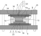
- the semiconductor device according to the seventh embodiment is made of ceramics on both surfaces of the heat conductive plate 3 made of metal between the upper and lower surfaces of the plate-like semiconductor module 8 and the cooler 9.
- a composite 23 formed with an insulating film 2 is disposed, and the insulating film 2 on the semiconductor module 8 side of the composite 23 covers the surface of the circuit pattern 11a of the circuit board 11 opposite to the semiconductor element 10. Yes.
- the insulating films 2 on both surfaces of the heat conducting plate 3 are smaller than the area of the heat conducting plate 3, and are formed inside the ends of the heat conducting plate 3.
- the insulating film 2 is not formed up to the end of the heat conducting plate 3. In other words, the heat conductive plate 3 protrudes from the end of the insulating film 2.
- the insulating films 2 on both surfaces of the heat conducting plate 3 are formed inside the ends of the heat conducting plate 3, as shown in FIG. It is desirable to be curved. In other words, it is desirable that the portion where the heat conducting plate 3 is exposed is bent toward the semiconductor module 8 side. In such a semiconductor device, when the cooler 9 has a burr protruding toward the semiconductor module 8 side, the heat conducting plate 3 and the cooler 9 may be in electrical contact. In this case, the cooler 9 side Since the insulating film 2 no longer plays the role of insulation, there is a possibility that the insulating property is lowered. However, in FIG. 17, the insulating film 2 is not formed on the outer peripheral portion of the heat conductive plate 3, and the heat conductive plate 3 However, since the heat conducting plate 3 can be prevented from coming into direct contact with the cooler 9, the insulation reliability can be improved.
- the semiconductor device according to the eighth embodiment is configured by arranging coolers 9 on the upper and lower surfaces of a plate-like semiconductor module 28 as shown in FIG.
- the semiconductor module 28 includes a pair of metal plate mold bodies 17a and 17b (hereinafter sometimes referred to as the metal plate mold body 17), and the semiconductor element 10 made of resin.
- the semiconductor element mold body 18 molded in 14b is laminated so as to be sandwiched between a pair of metal plate mold bodies 17a and 17b.
- the pair of metal plate mold bodies 17a and 17b is configured by embedding a circuit board 11 made of metal in a resin 14a so that both main surfaces of the circuit pattern portion 11a are exposed.
- the circuit pattern portion 11a functions as a path for flowing a current controlled by the semiconductor element 10 to the wiring portion 11b, and also serves as a conduction path for heat generated in the semiconductor element 10. Therefore, the main surface of the circuit pattern portion 11a is The metal plate mold body 17 is exposed on both sides in the thickness direction.
- the resin 14 b is filled, and the semiconductor element mold body 18 is formed together with the semiconductor element 10. That is, the semiconductor element mold body 18 in which the semiconductor element 10 is molded in the resin 14b is sandwiched between the metal plate mold bodies 17a and 17b.
- the resin 14b for molding the semiconductor element 10 is desirably softer and easier to deform than the resin 14a used for the metal plate mold body 17.
- the insulating film 2 is formed on the surfaces of the metal plate molds 17a and 17b opposite to the semiconductor element 10 so as to cover the main surface of the circuit pattern portion 11a, thereby forming a composite 24.
- the insulating film 2 is directly formed on the main surface exposed from the resin 14a of the circuit pattern portion 11 and the surface of the resin 14a around the exposed main surface.
- the insulating film 2 of the composite 24 has a plurality of flat gaps 4 having a large dimension in the direction along the main surface of the metal plate 3 with respect to the dimension in the thickness direction of the insulating film 2. In addition, it is possible to secure good thermal conductivity.
- the cooler 9 made of metal is arranged on the upper and lower surfaces of the plate-like semiconductor module 28 as described above, and the semiconductor device is configured.
- the cooler 9 has an area larger than that of the semiconductor module 28, the plate-like semiconductor module 28 is sandwiched between the pair of coolers 9, and the gap between the pair of coolers 9 is secured by the fastening member 15 attached to the cooler 9.
- the semiconductor module 28 and the cooler 9 are integrated with each other by pressing the cooler 9 toward the semiconductor module 28 side.
- grease 16 is interposed between the cooler 9 and the composite body 24 (metal plate mold bodies 17a and 17b) in order to improve thermal conductivity.
- a pair of metal plate mold bodies 17a and 17b is prepared (first step).
- the pair of metal plate molds 17a and 17b is formed by embedding the circuit board 11 in the resin 14a so that both main surfaces of the circuit pattern portion 11a are exposed.
- the metal plate mold bodies 17a and 17b are formed by, for example, injection molding so that the circuit board 11 is embedded in the resin 14a so that both main surfaces of the circuit pattern portion 11a are exposed.
- the composite body 24 is formed by covering one main surface of the circuit pattern portion 11b of the metal plate mold bodies 17a and 17b with the insulating film 2 made of ceramic.
- the insulating film 2 of the composite 24 has a plurality of flat voids 4 having a large dimension in the direction along the main surface of the metal plate 3 with respect to the dimension of the insulating film 2 in the thickness direction.
- the semiconductor element 10 is sandwiched between the pair of metal plate molds 17a and 17b where the insulating film 2 is not formed, and the semiconductor element 10 and the circuit pattern portion 11a are electrically connected.
- Step as shown in FIG. 22 (a), by filling the resin 14b around the semiconductor element 10 between the pair of metal plate mold bodies 17a, 17b (third step), The semiconductor module 28 can be produced.
- the cooler 9 is disposed on the insulating film 2 of the semiconductor module 28 via the grease 16 (fourth step), and the pair of coolers 9 is used for the semiconductor.
- the semiconductor module 28 and the cooler 9 are integrally fixed by sandwiching the module 28 and tightening the fastening member 15 attached to the cooler 9 and pressing the cooler 9 toward the semiconductor module 28 (fifth step).
- a semiconductor device can be manufactured. In such a semiconductor device, the semiconductor module 28 and the cooler 9 are not joined, but are sandwiched and integrated by the cooler 9, so that the thermal stress between the semiconductor module 28 and the cooler 9 is integrated. Can be reduced.
- one main surface of the circuit pattern portion 11a of the pair of metal plate mold bodies 17a and 17b, in which both main surfaces of the circuit pattern portion 11a are exposed in the resin 14a, is an insulating film. 2
- the semiconductor element 10 is sandwiched between the pair of metal plate molds 17 a and 17 b, and then the semiconductor element 10 is interposed between the pair of metal plate molds 17 a and 17 b.
- the formation state of the insulating film 2 of the composite 24 is confirmed with, for example, a microscope, or an insulation resistance measuring conductor is disposed on the insulating film 2 to After measuring the insulation resistance between the plate 11 and the insulation resistance measuring conductor and confirming the insulation of the insulating film 2, the semiconductor element 10 is sandwiched between the pair of metal plate molds 17a and 17b, and the semiconductor module
- the composite 28 having a defective insulating film formation can be removed as a defective, the semiconductor element 10 is sandwiched between the composite 24 having a good insulating film formation state, and the semiconductor module 28 is manufactured.
- the defective rate of modules can be reduced, and the amount of loss due to defective insulation film formation can be reduced.
- the insulating film 2 of the composite 24 has a plurality of flat gaps 4 having a dimension in the direction along the main surface of the metal plate 3 with respect to the dimension in the thickness direction of the insulating film 2, the withstand voltage characteristics Can be improved.
- the metal plate molds 17a and 17b use a hard resin 14a, and the resin 14b filled around the semiconductor element 10 between the pair of metal plate molds 17a and 17b is easily softly deformed. Even if the insulating film 2 formed on the metal plate mold bodies 17a and 17b is not parallel by using a material, the resin between the metal plate mold bodies 17a and 17b can be obtained by fastening the fastening member 15. 14b is deformed, and no contact of the cooler 9 with the insulating film 2 occurs, so that the reliability of the insulating film 2 can be improved.
- an aluminum substrate having a square main surface of 20 mm ⁇ 20 mm and a thickness of 2 mm was used as the substrate which is the metal plate 3. This aluminum substrate was mirror-polished on one side.
- the alumina powder having an average particle size of 0.5 ⁇ m was used as the aerosol raw material powder. This was heat-treated at the temperature shown in Table 1 for 12 hours. 50 g of this alumina powder was put into 450 ml glass bottles connected to the nozzles 6a and 6b, respectively, covered with piping, and set in a film forming system.
- a film forming system includes a film forming apparatus that performs film forming, an aerosol generating apparatus that supplies aerosol to a chamber in the film forming apparatus, a vacuum pump that sucks the inside of the chamber to make negative pressure, and an aerosol generating apparatus.
- a gas supply device that supplies a gas serving as a dispersion medium to the glass bottle is provided.
- the inside of the glass bottle constituting the chamber and the aerosol generator was evacuated to 10 Pa with a vacuum pump (rotary pump and mechanical booster pump).
- aerosol was generated by introducing a gas (hereinafter also referred to as a film forming gas) from the gas supply device into the glass bottle while vibrating the glass bottle from side to side.
- a gas hereinafter also referred to as a film forming gas
- the amplitude of the glass bottle a was 1 mm
- the vibration period was 1000 times / min
- the film forming gas flow rate was 10 L / min.
- the conditions for generating the aerosol to be ejected from the nozzle 6b were as follows.
- the amplitude of the glass bottle was 0.5 mm
- the film forming gas flow rate was 5 L / min
- the vibration period of the glass bottle b and the type of film forming gas were as shown in Table 1.
- the opening size of the nozzles 6a and 6b is 0.4 mm ⁇ 10 mm, and has a rectangular opening.
- the substrate 3 was reciprocated with respect to the nozzles 6a and 6b.
- the conditions were an amplitude of 10 mm and the speed and number of times shown in Table 1.
- the distance between the nozzles 6a and 6b and the substrate 3 was fixed at 15 mm.
- the alumina insulating film 2 having a thickness of 50 ⁇ m was formed in an area of 10 mm ⁇ 10 mm on the surface of the substrate 3.
- the aerosol concentration changes periodically. For example, sample no. In the case of 2, the glass bottle is vibrated at a cycle of 600 times / min, so that the nozzle 6b has a maximum aerosol concentration 20 times per second.
- the moving speed of the substrate 3 is 0.1 mm / s, the aerosol concentration becomes maximal on the substrate 3 every 5 ⁇ m in the moving direction of the substrate, and the amount of the alumina particles 5b adhering to the substrate 3 increases at that portion.
- the thickness of the composite 1 is measured with a micrometer after film formation, and the thickness of the insulating film 2 is subtracted from the thickness of the substrate 3 measured before film formation. Asked. As a result, all the insulating films had a thickness of 50 ⁇ m.
- the formation state of the void 4 inside the insulating film 2 was confirmed by ion-etching the cut surface of each sample and observing the cross section of the insulating film 2 with a scanning electron microscope (SEM).
- SEM scanning electron microscope
- the shape and the number of the voids 4 were obtained by taking 10 SEM photographs at a magnification of 3000 times, confirming the aspect ratio A: B of all voids that can be confirmed in an arbitrary 10 ⁇ 10 ⁇ m region of each photo, and the aspect ratio being 1 :
- the average value of the number was obtained by setting three or more as flat voids.
- the interval between the gaps in the thickness direction of the insulating film 2 and the overlapping state are measured on the SEM photograph, and three or more flat gaps 4 are in the thickness direction of the insulating film 2.
- a set of flat gaps 4 adjacent to each other at intervals of 5 ⁇ m or less are 60% of the length B of the gap having a smaller length in the direction along the main surface of the metal plate 3.
- Table 2 shows the aspect ratio, shape, number and alignment of the voids in each sample. In any of the samples, no difference depending on the direction of the cut surface was observed in the gap formation state inside the insulating film.
- the displacement of the surface of the substrate 3 on the side where the insulating film 2 is not formed was measured with a stylus type surface roughness meter.
- the measured displacement amount was substituted into the Stoney equation together with the measurement length, the Young's modulus and Poisson's ratio of the substrate, the thickness of the substrate and the insulating film, and the stress of the insulating film was calculated.
- the measurement length was 5 mm.
- the insulation reliability of the composite is evaluated by masking the surface of the insulating film 2 by removing the ⁇ 5 range, depositing platinum on the surface of the insulating film, pressing a SUS electrode of ⁇ 4, and applying a load of 500 g Was performed.
Abstract
Provided are a complex capable of maintaining high insulation reliability, a semiconductor device using the complex, and a method for fabricating the semiconductor device which can decrease the financial loss that accompanies inadequate formation of an insulation film. The complex is provided with metal plates (3) and an insulation film (2) provided on the main surface of at least one of the metal plates (3). A plurality of flattened spaces (4) having a larger dimension in the direction along the main surface of the metal plates (3) than the dimension in the thickness direction of the insulation film (2) are present inside the insulation film (2). This type of complex (1) is preferable used in a semiconductor device wherein the complex (1) is positioned between a semiconductor module (8) integrally formed by means of resin (14) from a pair of circuit boards (11) and a semiconductor element (10) that is provided between the circuit boards (11) and controls the current flow in the circuit boards (11), and a cooler (9) provided on each surface on the side opposite the semiconductor element (10) of the circuit boards (11), the complex (1) being positioned in such a way that the insulation film (2) of the complex (1) covers the surface of a circuit pattern unit (11a).
Description
本発明は、絶縁放熱性に優れた複合体およびそれを用いた半導体装置、半導体モジュールならびにその製法に関するものである。
The present invention relates to a composite excellent in insulating heat dissipation, a semiconductor device using the same, a semiconductor module, and a manufacturing method thereof.
電気自動車、ハイブリッド自動車のインバータに用いられる発熱を伴うIGBT(Insulated Gate Bipolar Transistor)、パワートランジスタにおいては、半導体素子を保護するために冷却が必要であるとともに電気的絶縁性を確保する必要がある。
In IGBTs (Insulated Gate Bipolar Transistors) and power transistors that are used in inverters for electric vehicles and hybrid vehicles, it is necessary to cool and protect the semiconductor elements in order to protect the semiconductor elements.
従来、冷却効率を高めるために半導体素子の両面に金属からなる回路パターン部をそれぞれ配置し、これらの回路パターン部に金属からなる冷却器をそれぞれ配置し、半導体素子が発する熱を、回路パターン部を介して冷却器に熱伝導させ冷却する構造が提案されており(特許文献1、2参照)、回路パターン部と冷却器との間の電気的絶縁性を確保するために、従来、厚みが0.2~1mm程度のセラミック板を配置していた。
Conventionally, in order to improve cooling efficiency, circuit pattern portions made of metal are respectively arranged on both sides of a semiconductor element, and coolers made of metal are respectively arranged on these circuit pattern portions, and the heat generated by the semiconductor element is In order to ensure electrical insulation between the circuit pattern portion and the cooler, a structure has been proposed in which heat is conducted to the cooler via the cooling (see Patent Documents 1 and 2). A ceramic plate of about 0.2 to 1 mm was disposed.
しかしながら、近年においては、半導体素子にさらに大電流が印加されるようになり、その発熱量も大きくなっており、従来のセラミック板では、回路パターン部と冷却器との間の電気的絶縁性は確保できるものの、十分な絶縁性を確保しようとするとセラミック板が厚くなるため、また、セラミック板と回路パターンとの間に密着性向上のために塗布されるグリースが熱抵抗となり、回路パターン部から冷却器への熱伝導性が不充分であった。そこで、近年では、回路パターン部と冷却器との間の電気的絶縁性を確保するため、回路パターン部を被覆するように数μm~500μmのセラミックスからなる絶縁膜を形成することが提案されている(特許文献3参照)。
However, in recent years, a larger current has been applied to the semiconductor element, and the amount of heat generated has also increased. With conventional ceramic plates, the electrical insulation between the circuit pattern portion and the cooler is low. Although it is possible to secure sufficient insulation, the ceramic plate becomes thicker, and the grease applied to improve the adhesion between the ceramic plate and the circuit pattern becomes a thermal resistance. Insufficient thermal conductivity to the cooler. Therefore, in recent years, in order to ensure electrical insulation between the circuit pattern part and the cooler, it has been proposed to form an insulating film made of ceramics of several μm to 500 μm so as to cover the circuit pattern part. (See Patent Document 3).
しかしながら、従来の絶縁膜では、絶縁膜中に存在する残留応力により、高電圧を印加したときに膜が破壊してしまうという問題があった。
However, the conventional insulating film has a problem that the film is broken when a high voltage is applied due to a residual stress existing in the insulating film.
本発明は、高い絶縁信頼性を維持できる複合体およびそれを用いた半導体装置、半導体モジュールならびにその製法を提供することを目的とする。
An object of the present invention is to provide a composite that can maintain high insulation reliability, a semiconductor device using the composite, a semiconductor module, and a manufacturing method thereof.
本発明の複合体は、金属板と、該金属板の少なくとも一方の主面上に設けられたセラミックスからなる絶縁膜とを備える複合体であって、前記絶縁膜の内部には、前記絶縁膜の厚さ方向の寸法に対して前記金属板の主面に沿う方向の寸法が大きい扁平な空隙が複数存在することを特徴とする。
The composite of the present invention is a composite comprising a metal plate and an insulating film made of ceramics provided on at least one main surface of the metal plate, and the insulating film is provided inside the insulating film. There are a plurality of flat voids having a large dimension in the direction along the main surface of the metal plate with respect to the dimension in the thickness direction.
また、本発明の半導体装置は、一対の金属からなる回路板と、該一対の回路板間に配置された半導体素子とが樹脂により一体に成形され、前記回路板の前記半導体素子とは反対側の面が樹脂からそれぞれ露出した半導体モジュールと、前記回路板の前記半導体素子とは反対側の面にそれぞれ設けられた冷却器とを具備してなり、前記回路板と前記冷却器との間に、前記複合体を、該複合体の前記絶縁膜が前記回路板の面を覆うように配置してなることを特徴とする。
In the semiconductor device of the present invention, a pair of metal circuit boards and a semiconductor element disposed between the pair of circuit boards are integrally formed of resin, and the circuit board is opposite to the semiconductor elements. Each of the semiconductor modules exposed from the resin and a cooler provided on the surface of the circuit board opposite to the semiconductor element, and between the circuit board and the cooler. The composite is arranged such that the insulating film of the composite covers the surface of the circuit board.
さらに、本発明の半導体装置の製法は、一対の金属からなる回路板と、該一対の回路板間に配置された半導体素子とが樹脂により一体に成形され、前記回路板の前記半導体素子とは反対側の面が樹脂からそれぞれ露出した半導体モジュールを作製する第1工程と、前記複合体を、前記半導体モジュールの前記回路板の露出した面と冷却器との間に、前記回路板の面を前記絶縁膜が覆うようにそれぞれ配置する第2工程とを具備することを特徴とする。
Further, according to the method of manufacturing a semiconductor device of the present invention, a circuit board made of a pair of metals and a semiconductor element disposed between the pair of circuit boards are integrally formed of resin, and the semiconductor element of the circuit board is A first step of producing a semiconductor module in which opposite surfaces are respectively exposed from a resin; and the composite is disposed between the exposed surface of the circuit board of the semiconductor module and a cooler. And a second step of disposing the insulating film so as to cover the insulating film.
また、本発明の半導体モジュールは、金属板が樹脂によりモールドされ、前記金属板の両主面が前記樹脂から露出した一対の金属板モールド体と、半導体素子が樹脂によりモールドされ、前記半導体素子の電極部が前記樹脂から露出した半導体素子モールド体とが、一対の前記金属板間に前記半導体素子が配置されるように積層され、前記半導体素子と前記金属板とが電気的に接続されてなり、前記金属板モールド体は、前記金属板の前記半導体素子と接続されていない側の主面がセラミックスからなる絶縁膜で被覆されており、前記絶縁膜の内部には、前記絶縁膜の厚さ方向の寸法に対して前記金属板の主面に沿う方向の寸法が大きい扁平な空隙が複数存在することを特徴とする。
Further, in the semiconductor module of the present invention, a metal plate is molded with a resin, a pair of metal plate mold bodies in which both main surfaces of the metal plate are exposed from the resin, and a semiconductor element is molded with the resin. A semiconductor element mold body having an electrode portion exposed from the resin is laminated so that the semiconductor element is disposed between a pair of the metal plates, and the semiconductor element and the metal plate are electrically connected. In the metal plate mold body, the main surface of the metal plate that is not connected to the semiconductor element is covered with an insulating film made of ceramics, and the insulating film has a thickness within the insulating film. A plurality of flat air gaps having a large dimension in the direction along the main surface of the metal plate with respect to the dimension in the direction exist.
本発明の半導体モジュールの製法は、金属板を、該金属板の両主面が露出するように樹脂によりモールドしてなり、前記金属板の一方の主面にセラミックスからなる絶縁膜を被覆し、かつ前記絶縁膜の内部には、前記絶縁膜の厚さ方向の寸法に対して前記金属板の主面に沿う方向の寸法が大きい扁平な空隙が複数存在する一対の金属板モールド体を準備する第1工程と、前記一対の金属板モールド体の前記絶縁膜が形成されていない側で半導体素子を挟み、前記半導体素子と前記金属板とを電気的に接続する第2工程と、前記一対の金属板モールド体間の前記半導体素子の周囲に樹脂を充填する第3工程とを具備することを特徴とする。
The method for producing a semiconductor module according to the present invention is obtained by molding a metal plate with a resin so that both main surfaces of the metal plate are exposed, and covering one main surface of the metal plate with an insulating film made of ceramics, In addition, a pair of metal plate molds in which a plurality of flat voids having a size in the direction along the main surface of the metal plate with respect to the size in the thickness direction of the insulating film are present inside the insulating film are prepared. A first step, a second step of sandwiching a semiconductor element on a side of the pair of metal plate molds where the insulating film is not formed, and electrically connecting the semiconductor element and the metal plate; And a third step of filling a resin around the semiconductor element between the metal plate mold bodies.
本発明によれば、絶縁膜中の残留応力が緩和され、絶縁膜の耐電圧特性が向上するため、高い絶縁信頼性を維持できる。
According to the present invention, the residual stress in the insulating film is relaxed and the withstand voltage characteristic of the insulating film is improved, so that high insulation reliability can be maintained.
(第1の実施形態)
第1の実施形態である複合体について、図1をもとに説明する。複合体1は、金属板3と、金属板3の少なくとも一方の主面上に設けられた絶縁膜2とを備えている。絶縁膜2は、酸化珪素、酸化アルミニウム、窒化珪素、窒化ホウ素および窒化アルミニウムの少なくとも一種のセラミックス微粒子から構成されたセラミックス層とされている。金属板3は、銅、アルミニウム、ニッケル、鉄、チタン、モリブデンのうち少なくともいずれか一種の金属からなり、特にアルミニウムからなることが望ましい。金属板3の材質は特に限定されるものではなく、熱伝導性が良好な金属であれば良い。また、金属板3は、金属の熱伝導面が主面として露出していれば、樹脂等に埋設された状態でも差し支えなく、露出した金属主面の周囲の樹脂面上に絶縁膜が形成されていてもよい。なお、本明細書でいう金属とは、上述した金属だけに限らず、その金属の合金も含む概念である。 (First embodiment)
The composite body which is 1st Embodiment is demonstrated based on FIG. Thecomposite 1 includes a metal plate 3 and an insulating film 2 provided on at least one main surface of the metal plate 3. The insulating film 2 is a ceramic layer made of at least one kind of ceramic fine particles of silicon oxide, aluminum oxide, silicon nitride, boron nitride, and aluminum nitride. The metal plate 3 is made of at least one of copper, aluminum, nickel, iron, titanium, and molybdenum, and is particularly preferably made of aluminum. The material of the metal plate 3 is not particularly limited as long as the metal has good thermal conductivity. The metal plate 3 may be embedded in a resin or the like as long as the heat conduction surface of the metal is exposed as a main surface, and an insulating film is formed on the resin surface around the exposed metal main surface. It may be. In addition, the metal as used in this specification is the concept containing not only the metal mentioned above but the alloy of the metal.
第1の実施形態である複合体について、図1をもとに説明する。複合体1は、金属板3と、金属板3の少なくとも一方の主面上に設けられた絶縁膜2とを備えている。絶縁膜2は、酸化珪素、酸化アルミニウム、窒化珪素、窒化ホウ素および窒化アルミニウムの少なくとも一種のセラミックス微粒子から構成されたセラミックス層とされている。金属板3は、銅、アルミニウム、ニッケル、鉄、チタン、モリブデンのうち少なくともいずれか一種の金属からなり、特にアルミニウムからなることが望ましい。金属板3の材質は特に限定されるものではなく、熱伝導性が良好な金属であれば良い。また、金属板3は、金属の熱伝導面が主面として露出していれば、樹脂等に埋設された状態でも差し支えなく、露出した金属主面の周囲の樹脂面上に絶縁膜が形成されていてもよい。なお、本明細書でいう金属とは、上述した金属だけに限らず、その金属の合金も含む概念である。 (First embodiment)
The composite body which is 1st Embodiment is demonstrated based on FIG. The
絶縁膜2の内部には、絶縁膜2の厚さ方向の寸法に対して金属板3の主面に沿う方向の寸法が大きい扁平な空隙4が複数存在している。このような構成を有することにより、絶縁膜2中に存在する残留応力が緩和され、複合体1に高電圧を印加した際も絶縁膜2の破壊や空隙4の進展拡大による絶縁膜2の剥離を防止できる。なお、ここでいう扁平な空隙とは、図2に示すように、絶縁膜2の厚さ方向における空隙の寸法をA、金属板3の主面に沿う方向における空隙の寸法をBとしたとき、アスペクト比A:Bが1:3以上である空隙をさす。
Inside the insulating film 2, there are a plurality of flat voids 4 having a dimension in the direction along the main surface of the metal plate 3 with respect to the dimension in the thickness direction of the insulating film 2. By having such a configuration, the residual stress existing in the insulating film 2 is relaxed, and even when a high voltage is applied to the composite 1, the insulating film 2 is peeled off due to the breakdown of the insulating film 2 and the expansion of the gap 4. Can be prevented. Note that the flat air gap referred to here is when the dimension of the air gap in the thickness direction of the insulating film 2 is A and the dimension of the air gap in the direction along the main surface of the metal plate 3 is B as shown in FIG. , Refers to voids having an aspect ratio A: B of 1: 3 or more.
一般的に絶縁膜2中に存在する空隙4は、図8のように絶縁膜2を構成するセラミック粒子5に囲まれた歪な形状を有している。このような形状の空隙でも、絶縁膜2中に存在する残留応力を緩和することは可能だが、絶縁膜2に高電圧を印加した際、歪な形状の空隙4内で局所的な電界集中が起こり、部分放電が発生して絶縁膜2にダメージを与え強度を低下させてしまう。そのため、絶縁膜2の断面において、空隙4全体の占有面積に対して、扁平な空隙4の面積比率が95%以上であることが望ましい。扁平な空隙4の面積比率は、絶縁膜2の切断面をイオンエッチングして走査型電子顕微鏡(SEM)で観察し、画像解析により任意の領域に存在する全ての空隙4の占有面積を算出し、そのうちアスペクト比がA:Bが1:3以上である空隙の面積比率を算出することで確認できる。
Generally, the void 4 present in the insulating film 2 has a distorted shape surrounded by ceramic particles 5 constituting the insulating film 2 as shown in FIG. Even with such a gap, the residual stress existing in the insulating film 2 can be relaxed. However, when a high voltage is applied to the insulating film 2, local electric field concentration occurs in the distorted gap 4. As a result, partial discharge occurs, damages the insulating film 2 and decreases the strength. Therefore, in the cross section of the insulating film 2, it is desirable that the area ratio of the flat gap 4 is 95% or more with respect to the occupied area of the whole gap 4. The area ratio of the flat gap 4 is calculated by calculating the occupied area of all the gaps 4 existing in an arbitrary region by performing ion etching on the cut surface of the insulating film 2 and observing with a scanning electron microscope (SEM). Of these, the aspect ratio can be confirmed by calculating the area ratio of the voids in which A: B is 1: 3 or more.
扁平な空隙4の金属板3の主面に沿う方向の寸法Bは、0.5~10μmであることが望ましい。扁平な空隙4の寸法をこの範囲とすることにより、絶縁膜2中に存在する残留応力の緩和効果が得られるとともに、空隙4が進展することによる絶縁膜2の剥離を防止できる。また、扁平な空隙4の絶縁膜2の厚さ方向の寸法Aは、1μm以下であることが望ましい。これは、絶縁膜2に高電圧を印加した際、絶縁膜2中に存在する空隙4内で発生して絶縁膜2の破壊原因となる部分放電が、絶縁膜2の厚さ方向すなわち電圧印加方向の空隙寸法Aが小さいほど発生しにくいためである。なお、金属板3の主面側から扁平な空隙4を見た場合、最大径が10μm以下の円形または多角形の島状の空隙4が周期的に分布している。空隙4がこのような分布を示すことにより、絶縁膜2中の残留応力の緩和効果が向上する。
The dimension B of the flat gap 4 in the direction along the main surface of the metal plate 3 is preferably 0.5 to 10 μm. By setting the dimension of the flat gap 4 within this range, the effect of relieving the residual stress existing in the insulating film 2 can be obtained, and peeling of the insulating film 2 due to the progress of the gap 4 can be prevented. In addition, the dimension A in the thickness direction of the insulating film 2 of the flat gap 4 is desirably 1 μm or less. This is because when a high voltage is applied to the insulating film 2, the partial discharge that occurs in the gap 4 existing in the insulating film 2 and causes the breakdown of the insulating film 2 is caused by the thickness direction of the insulating film 2, that is, voltage application. This is because the smaller the gap dimension A in the direction, the less likely it is to occur. In addition, when the flat space | gap 4 is seen from the main surface side of the metal plate 3, the circular or polygonal island-shaped space | gap 4 whose maximum diameter is 10 micrometers or less is periodically distributed. When the voids 4 exhibit such a distribution, the effect of relaxing the residual stress in the insulating film 2 is improved.
また、扁平な空隙4は、絶縁膜2の断面10μm×10μmの領域に、10~80個存在していることが望ましい。絶縁膜2の内部に存在する扁平な空隙4の個数は、絶縁膜2の切断面をイオンエッチングしてSEMで観察することで確認できる。扁平な空隙4の個数をこの範囲とすることにより、絶縁膜2中の残留応力の緩和効果がさらに向上するとともに、過剰に存在する空隙が進展して互いに連結することによる絶縁膜2の剥離を防止できる。
Further, it is desirable that 10 to 80 flat gaps 4 exist in a region having a cross section of 10 μm × 10 μm of the insulating film 2. The number of flat voids 4 present inside the insulating film 2 can be confirmed by ion-etching the cut surface of the insulating film 2 and observing with a SEM. By setting the number of flat voids 4 within this range, the effect of mitigating residual stress in the insulating film 2 is further improved, and separation of the insulating film 2 due to the expansion of excess voids that are connected to each other is achieved. Can be prevented.
また、絶縁膜2の厚さは例えば10~100μmであり、エアロゾルデポジション法(以下、AD法という場合もある)、スパッタリング法等の薄膜法により金属板3の主面上に直接形成される。IGBT等の用途においては、1000V程度の耐電圧特性が求められるが、100V/μmの電界が印加されると扁平な空隙4の内部においても部分放電が発生してしまうため、絶縁膜2は10μm以上の厚さを有する必要がある。また、複合体1の放熱性を良好に維持するために、絶縁膜2の厚さは100μm以下とし、特に60μm以下とすることで、残留応力による絶縁膜2の破壊を効果的に防止できるとともに、成膜に要する時間とコストを削減できる。
The thickness of the insulating film 2 is, for example, 10 to 100 μm, and is formed directly on the main surface of the metal plate 3 by a thin film method such as an aerosol deposition method (hereinafter also referred to as an AD method) or a sputtering method. . In applications such as IGBTs, a withstand voltage characteristic of about 1000 V is required. However, when an electric field of 100 V / μm is applied, partial discharge occurs even inside the flat gap 4, so that the insulating film 2 has a thickness of 10 μm. It is necessary to have the above thickness. Moreover, in order to maintain the heat dissipation of the composite 1 satisfactorily, the thickness of the insulating film 2 is set to 100 μm or less, particularly 60 μm or less, thereby effectively preventing the insulating film 2 from being broken due to residual stress. The time and cost required for film formation can be reduced.
複合体1は、絶縁膜2を上記のような材質、構造、厚みとすることにより、絶縁性を確保できるとともに、高い機械的強度を得ることができ、さらに良好な熱伝導性を得ることができる。
By making the insulating film 2 the material, structure, and thickness as described above, the composite 1 can ensure insulation, obtain high mechanical strength, and obtain better thermal conductivity. it can.
絶縁膜を形成する際、特許文献3に記載されているようなエアロゾルデポジション法で形成すると、0.1~5μm程度の脆性材料微粒子をガス中に均一に分散させたエアロゾルを基板に吹き付けることにより、緻密な絶縁膜が得られるという特徴があり、得られた絶縁膜は焼結体に比べて高い絶縁性能を持つ。
When forming an insulating film, if formed by an aerosol deposition method as described in Patent Document 3, an aerosol in which brittle material fine particles of about 0.1 to 5 μm are uniformly dispersed in a gas is sprayed onto the substrate. Thus, a dense insulating film can be obtained, and the obtained insulating film has a higher insulating performance than a sintered body.
エアロゾルの発生について説明する。ガラス瓶にエアロゾルの原料粉末であるセラミックス微粒子を投入し、配管付きの蓋をする。ガラス瓶を振動させながら、ガラス瓶内に分散媒となる気体を吹き込む。分散媒となる気体としては、窒素、ヘリウム、アルゴン、空気などが用いられる。
Explain the generation of aerosol. Put ceramic fine particles, which are aerosol raw material powder, into a glass bottle and cover with piping. While vibrating the glass bottle, a gas as a dispersion medium is blown into the glass bottle. Nitrogen, helium, argon, air, etc. are used as a gas used as a dispersion medium.
エアロゾルデポジション法により、内部に扁平な空隙4を有する絶縁膜2を形成する場合には、図6に示すように2つのノズル6a、6bを用いて、それぞれ粒子の濃度および速度の異なる2種類のエアロゾルを金属板3となる基板に吹き付けることにより形成できる。ノズル6aは高濃度かつ高速のセラミック粒子5aを噴出し、ノズル6bは低濃度かつ低速のセラミック粒子5bを噴出する。これらのノズル6a、6bが基板上を往復することで、図7(a)のように緻密な絶縁層2aと疎な絶縁層2bが積層された絶縁膜2を有する複合体1が得られる。
When the insulating film 2 having the flat gap 4 is formed by the aerosol deposition method, two types having different particle concentrations and speeds are used by using two nozzles 6a and 6b as shown in FIG. Can be formed by spraying the aerosol on the substrate to be the metal plate 3. The nozzle 6a ejects high-concentration and high-speed ceramic particles 5a, and the nozzle 6b ejects low-concentration and low-speed ceramic particles 5b. By reciprocating these nozzles 6a and 6b on the substrate, a composite 1 having an insulating film 2 in which a dense insulating layer 2a and a sparse insulating layer 2b are laminated as shown in FIG. 7A is obtained.
ノズル6a、6bから噴出するエアロゾルの濃度は、エアロゾル供給源であるガラス瓶の振幅と周波数により調整できる。すなわち、ノズル6aから噴出するエアロゾルの供給源であるガラス瓶aの振幅を大きく、周波数を高くすることで、ノズル6aから高濃度のエアロゾルを噴出させることができ、ノズル6bから噴出するエアロゾルの供給源であるガラス瓶bの振幅を小さく、周波数を低くすることで、ノズル6bから低濃度のエアロゾルを噴出させることができる。
The concentration of the aerosol ejected from the nozzles 6a and 6b can be adjusted by the amplitude and frequency of the glass bottle serving as the aerosol supply source. That is, by increasing the amplitude and the frequency of the glass bottle a which is the supply source of the aerosol ejected from the nozzle 6a, it is possible to eject a high concentration aerosol from the nozzle 6a, and the supply source of the aerosol ejected from the nozzle 6b By reducing the amplitude of the glass bottle b and lowering the frequency, low-concentration aerosol can be ejected from the nozzle 6b.
また、ガラス瓶を振動させることによってエアロゾルを発生させているので、ノズルから噴出するエアロゾル濃度は周期的に変化する。疎な絶縁層2bは強度が低いため、緻密な絶縁層2aとの界面から疎な絶縁層2bが剥離する部分が周期的に発生し、図7(b)のように扁平な空隙4が形成される。なお、疎な絶縁層2bが厚すぎると、疎な絶縁層2b内部に無数の歪な空隙4が形成され、それにより残留応力が緩和されるため、緻密な絶縁層2aとの界面からの剥離が起こらず、扁平な空隙4は形成されない。扁平な空隙4を形成するためには、疎な絶縁層2bの厚さが0.5μm以下となるように、ノズル6bから噴出するエアロゾル濃度を低下させることが重要である。また、緻密な絶縁層2aの厚さは1層あたり5μm以下となるように形成する。緻密な絶縁層2aの1層の厚さが5μmを超えると、扁平な空隙4による残留応力の緩和効果が低下する。緻密な絶縁層2aと疎な絶縁層2bは、それぞれ2層以上積層されていることが望ましい。
Moreover, since the aerosol is generated by vibrating the glass bottle, the concentration of the aerosol ejected from the nozzle changes periodically. Since the sparse insulating layer 2b has low strength, a portion where the sparse insulating layer 2b peels from the interface with the dense insulating layer 2a is periodically generated, and a flat gap 4 is formed as shown in FIG. 7B. Is done. If the sparse insulating layer 2b is too thick, an infinite number of distorted voids 4 are formed inside the sparse insulating layer 2b, and the residual stress is relieved, so that peeling from the interface with the dense insulating layer 2a occurs. Does not occur, and the flat gap 4 is not formed. In order to form the flat gap 4, it is important to reduce the concentration of aerosol ejected from the nozzle 6 b so that the thickness of the sparse insulating layer 2 b is 0.5 μm or less. The dense insulating layer 2a is formed to have a thickness of 5 μm or less per layer. If the thickness of one layer of the dense insulating layer 2a exceeds 5 μm, the effect of relieving the residual stress due to the flat gap 4 decreases. It is desirable that two or more dense insulating layers 2a and sparse insulating layers 2b are laminated.
なお、絶縁膜2の成膜に用いる分散媒としての気体は窒素であることが望ましい。空隙4の内部には成膜に用いた分散媒である気体が封入されており、窒素は他の気体と比較して放電開始電圧が高く、空隙4内での部分放電発生を抑制する効果がある。また、成膜に用いる原料粉末は、あらかじめ500℃以上で加熱処理しておくことが望ましい。原料粉末であるセラミックス微粒子を500℃以上で加熱処理することにより、セラミックス微粒子に付着している有機不純物を除去することができ、絶縁膜中に混入した有機不純物が電圧印加時にガス化することで発生するクラックや、絶縁膜の破壊を防止できる。
Note that the gas as a dispersion medium used for forming the insulating film 2 is preferably nitrogen. Gas that is a dispersion medium used for film formation is sealed inside the gap 4, and nitrogen has a higher discharge start voltage than other gases, and has the effect of suppressing the occurrence of partial discharge in the gap 4. is there. In addition, it is desirable that the raw material powder used for film formation is previously heat-treated at 500 ° C. or higher. By heat-treating the ceramic fine particles, which are the raw material powder, at 500 ° C. or more, organic impurities adhering to the ceramic fine particles can be removed, and the organic impurities mixed in the insulating film are gasified when a voltage is applied. It is possible to prevent the occurrence of cracks and the breakdown of the insulating film.
(第2の実施形態)
第2の実施形態である複合体について、図3をもとに説明する。本発明の第2の実施形態における複合体1では、絶縁膜2の内部に存在する複数の扁平な空隙4が、絶縁膜2の厚さ方向に5μm以下の間隔を置いて整列して扁平な空隙群を形成し、このような扁平な空隙群が金属板3の主面に沿う方向に所定間隔をおいて複数形成されている。このような構成を有することにより、絶縁膜2の厚さ方向で均一に応力が緩和され局所的な応力集中が抑えられるため、さらに絶縁膜2の耐電圧特性が向上する。 (Second Embodiment)
The composite body which is 2nd Embodiment is demonstrated based on FIG. In thecomposite body 1 according to the second embodiment of the present invention, a plurality of flat gaps 4 existing inside the insulating film 2 are aligned and spaced in the thickness direction of the insulating film 2 with an interval of 5 μm or less. A plurality of such flat gap groups are formed at predetermined intervals in the direction along the main surface of the metal plate 3. By having such a configuration, the stress is uniformly relieved in the thickness direction of the insulating film 2 and local stress concentration is suppressed, so that the withstand voltage characteristics of the insulating film 2 are further improved.
第2の実施形態である複合体について、図3をもとに説明する。本発明の第2の実施形態における複合体1では、絶縁膜2の内部に存在する複数の扁平な空隙4が、絶縁膜2の厚さ方向に5μm以下の間隔を置いて整列して扁平な空隙群を形成し、このような扁平な空隙群が金属板3の主面に沿う方向に所定間隔をおいて複数形成されている。このような構成を有することにより、絶縁膜2の厚さ方向で均一に応力が緩和され局所的な応力集中が抑えられるため、さらに絶縁膜2の耐電圧特性が向上する。 (Second Embodiment)
The composite body which is 2nd Embodiment is demonstrated based on FIG. In the
なお、複数の扁平な空隙4が整列している空隙群とは、図4に示すように、絶縁膜2の断面において、3個以上の扁平な空隙4が絶縁膜2の厚さ方向に互いに5μm以下の間隔をおいて並んでおり、互いに隣接する一組の扁平な空隙4が、金属板3の主面に沿う方向における長さが小さいほうの空隙4の長さB’に対して60%以上重なり合っているものをいう。なお、扁平な空隙群同士の間隔は、金属板3の主面に沿う方向において20μm以下であることが望ましい。これにより、金属板3の主面に沿う方向についてもより均一な応力の緩和効果が得られる。
In addition, as shown in FIG. 4, the gap group in which the plurality of flat gaps 4 are aligned is that three or more flat gaps 4 are mutually in the thickness direction of the insulating film 2 in the cross section of the insulating film 2. A pair of flat air gaps 4 arranged adjacent to each other at intervals of 5 μm or less are 60 with respect to the length B ′ of the air gap 4 having a smaller length in the direction along the main surface of the metal plate 3. It is the thing which overlaps more than%. In addition, it is desirable that the interval between the flat gap groups is 20 μm or less in the direction along the main surface of the metal plate 3. Thereby, a more uniform stress relaxation effect can be obtained in the direction along the main surface of the metal plate 3.
このような複合体1は、以下の手順によって作製される。ノズル6bから噴出されるエアロゾルは、ガラス瓶bの振動により一定周期で濃度が変化する。この振幅の周期と基板の往復周期を調整することによって、ノズル6bが基板上を往復移動する時に基板上の同一箇所でエアロゾル濃度が極大となる。その結果、複数の絶縁層が形成される過程で、疎な絶縁層2bが基板上の同一箇所で緻密な絶縁層2aとの界面から剥離し、絶縁膜2の厚さ方向に整列した扁平な空隙群が金属板の主面に沿う方向に所定の間隔をおいて複数形成された絶縁膜2を有する複合体1が得られる。
Such a complex 1 is produced by the following procedure. The concentration of the aerosol ejected from the nozzle 6b changes at a constant period due to the vibration of the glass bottle b. By adjusting the period of the amplitude and the reciprocating period of the substrate, the aerosol concentration becomes maximum at the same position on the substrate when the nozzle 6b reciprocates on the substrate. As a result, in the process of forming a plurality of insulating layers, the sparse insulating layer 2b peels off from the interface with the dense insulating layer 2a at the same location on the substrate, and is flat and aligned in the thickness direction of the insulating film 2 A composite 1 having an insulating film 2 in which a plurality of voids are formed at predetermined intervals in a direction along the main surface of the metal plate is obtained.
(第3の実施形態)
第3の実施形態である複合体について、図5をもとに説明する。本発明の第3の実施形態における複合体1では、絶縁膜2の内部に存在する扁平な空隙4の寸法が、絶縁膜2の厚さ方向の寸法Aに対し、金属板3の主面に沿う方向の寸法Bが5倍以上である。これにより、さらに絶縁膜2の耐電圧特性が向上する。 (Third embodiment)
The composite body which is 3rd Embodiment is demonstrated based on FIG. In the composite 1 according to the third embodiment of the present invention, the dimension of theflat gap 4 existing inside the insulating film 2 is on the main surface of the metal plate 3 with respect to the dimension A in the thickness direction of the insulating film 2. The dimension B along the direction is 5 times or more. Thereby, the withstand voltage characteristic of the insulating film 2 is further improved.
第3の実施形態である複合体について、図5をもとに説明する。本発明の第3の実施形態における複合体1では、絶縁膜2の内部に存在する扁平な空隙4の寸法が、絶縁膜2の厚さ方向の寸法Aに対し、金属板3の主面に沿う方向の寸法Bが5倍以上である。これにより、さらに絶縁膜2の耐電圧特性が向上する。 (Third embodiment)
The composite body which is 3rd Embodiment is demonstrated based on FIG. In the composite 1 according to the third embodiment of the present invention, the dimension of the
扁平な空隙4の金属板3の主面に沿う方向の寸法Bを大きくすることにより、絶縁膜2中に存在する残留応力の緩和効果が向上し、絶縁膜2の厚さ方向の寸法Aを小さくすることにより部分放電の開始電圧が高くなる。すなわち、扁平な空隙4の絶縁膜2の厚さ方向と金属板3の主面に沿う方向のアスペクト比A:Bは、1:5以上であることが望ましい。
By increasing the dimension B of the flat gap 4 in the direction along the main surface of the metal plate 3, the effect of mitigating residual stress existing in the insulating film 2 is improved, and the dimension A in the thickness direction of the insulating film 2 is increased. By making it smaller, the partial discharge start voltage becomes higher. That is, the aspect ratio A: B in the thickness direction of the insulating film 2 in the flat gap 4 and the direction along the main surface of the metal plate 3 is preferably 1: 5 or more.
このような、絶縁膜2の内部にアスペクト比の大きい扁平な空隙4を有する複合体1は、基板の往復速度を第1の実施形態および第2の実施形態の場合よりも高速にすることにより作製できる。基板の往復速度を高速にするとことで、より金属板3の主面に沿う方向に長い空隙4を有する絶縁膜2が形成され、所望の複合体1を得ることができる。
Such a composite 1 having a flat gap 4 with a large aspect ratio inside the insulating film 2 can be obtained by making the reciprocating speed of the substrate higher than in the case of the first and second embodiments. Can be made. By increasing the reciprocating speed of the substrate, the insulating film 2 having the longer gap 4 in the direction along the main surface of the metal plate 3 is formed, and the desired composite 1 can be obtained.
(第4の実施形態)
第4の実施形態である半導体装置について、図9を用いて説明する。第4の実施形態である半導体装置は、板状の半導体モジュール8の上下に冷却器9を配置して構成されている。 (Fourth embodiment)
A semiconductor device according to the fourth embodiment will be described with reference to FIG. The semiconductor device according to the fourth embodiment is configured by arrangingcoolers 9 above and below a plate-like semiconductor module 8.
第4の実施形態である半導体装置について、図9を用いて説明する。第4の実施形態である半導体装置は、板状の半導体モジュール8の上下に冷却器9を配置して構成されている。 (Fourth embodiment)
A semiconductor device according to the fourth embodiment will be described with reference to FIG. The semiconductor device according to the fourth embodiment is configured by arranging
半導体モジュール8は、図10、図11に示すように、回路パターン部11aを有する一対の金属からなる回路板11と、該一対の回路板11の回路パターン部11a間に配置され、回路板11における電流の流れを制御する半導体素子10とが樹脂14により一体に成形されて構成されている。
As shown in FIGS. 10 and 11, the semiconductor module 8 is disposed between a pair of metal circuit boards 11 having circuit pattern portions 11 a and the circuit pattern portions 11 a of the pair of circuit boards 11. The semiconductor element 10 for controlling the flow of current in is integrally formed with a resin 14.
すなわち、回路板11は、半導体素子10が電気的に接続される回路パターン部11aと、この回路パターン部11aに接続された配線部11bとから構成されており、回路パターン部11aは、半導体素子10で制御された電流を回路板11に流す経路として機能するとともに、半導体素子10で発生した熱の伝導経路となっている。回路パターン部11aの面は、半導体素子10で発生した熱の伝導経路となっているため、板状の半導体モジュール8の厚み方向の両側の面に露出している。配線部11bは、半導体モジュール8から外部に導出されている。
That is, the circuit board 11 includes a circuit pattern portion 11a to which the semiconductor element 10 is electrically connected and a wiring portion 11b connected to the circuit pattern portion 11a. 10 functions as a path through which the current controlled by 10 flows through the circuit board 11, and serves as a conduction path for heat generated in the semiconductor element 10. Since the surface of the circuit pattern portion 11 a is a conduction path for heat generated in the semiconductor element 10, the surface is exposed on both surfaces in the thickness direction of the plate-like semiconductor module 8. The wiring part 11b is led out from the semiconductor module 8 to the outside.
言い換えれば、半導体素子10が回路板11の回路パターン部11aで挟まれ、この状態で、回路板11が回路パターン部11aの半導体素子10と反対側の面が露出するように樹脂モールドされて半導体モジュール8が構成されている。
In other words, the semiconductor element 10 is sandwiched between the circuit pattern parts 11a of the circuit board 11, and in this state, the circuit board 11 is resin-molded so that the surface of the circuit pattern part 11a opposite to the semiconductor element 10 is exposed. Module 8 is configured.
回路板11は、銅、アルミニウム、ニッケル、鉄、チタン、モリブデンの何れか一種の金属からなるもので、特に銅、アルミニウムからなることが望ましい。回路板11の材質は、特に限定されるものではなく、熱伝導性が良好な金属であれば良い。これらの回路板11の厚みは、1~5mmとされている。なお、回路板11は金属からなるものであり、本明細書でいう金属とは、上述した金属だけに限らず、その金属の合金も含む概念である。
The circuit board 11 is made of any one kind of metal such as copper, aluminum, nickel, iron, titanium, and molybdenum, and is preferably made of copper or aluminum. The material of the circuit board 11 is not particularly limited as long as it is a metal having good thermal conductivity. The thickness of these circuit boards 11 is 1 to 5 mm. The circuit board 11 is made of a metal, and the term “metal” in the present specification is a concept including not only the metal described above but also an alloy of the metal.
一対の回路板11の回路パターン11aの間には半導体素子10が配置され、さらに、一対の回路板11間の間隔を確保するため、半導体素子10の上面に、金属からなる導電性スペーサ13が配置されている。半導体素子10には、制御信号を送るための配線12が接続されている。
A semiconductor element 10 is disposed between the circuit patterns 11 a of the pair of circuit boards 11, and a conductive spacer 13 made of metal is provided on the upper surface of the semiconductor element 10 in order to secure a gap between the pair of circuit boards 11. Is arranged. A wiring 12 for sending a control signal is connected to the semiconductor element 10.
半導体素子10は、下側の回路板11の回路パターン部11aと導電性接着剤で接合され、上側の導電性スペーサ13と導電性接着剤で接合され、導電性スペーサ13と上側の回路板11の回路パターン部11aとが導電性接着剤で接合され、これにより、半導体素子10と上下の回路板11とが電気的に接続されている。導電性スペーサ13も回路板11と同様の金属から形成されている。なお、一対の回路板11間の間隔を確保する必要がない場合には、導電性スペーサ13を設ける必要はなく、この場合には、半導体素子10と上側の回路板11の回路パターン部11aが導電性接着剤で接合されることになる。
The semiconductor element 10 is joined to the circuit pattern portion 11a of the lower circuit board 11 with a conductive adhesive, joined to the upper conductive spacer 13 with a conductive adhesive, and the conductive spacer 13 and the upper circuit board 11 are joined. The circuit pattern portion 11a is joined with a conductive adhesive, whereby the semiconductor element 10 and the upper and lower circuit boards 11 are electrically connected. The conductive spacer 13 is also made of the same metal as the circuit board 11. In addition, when it is not necessary to ensure the space | interval between a pair of circuit boards 11, it is not necessary to provide the conductive spacer 13, In this case, the circuit pattern part 11a of the semiconductor element 10 and the upper circuit board 11 is provided. It will be joined with a conductive adhesive.
そして、半導体モジュール1の上下面と冷却器3との間には、図9に示したように、金属からなる熱伝導板3にセラミックスからなる絶縁膜2を形成してなる複合体1が配置されており、複合体1の絶縁膜2が、回路板11の回路パターン11aの半導体素子7と反対側の面を覆っている。この複合体1には、第1~第3の実施形態のいずれかに示した複合体1を用いる。
Between the upper and lower surfaces of the semiconductor module 1 and the cooler 3, as shown in FIG. 9, a composite body 1 in which an insulating film 2 made of ceramic is formed on a heat conductive plate 3 made of metal is disposed. The insulating film 2 of the composite 1 covers the surface of the circuit pattern 11 a of the circuit board 11 opposite to the semiconductor element 7. As this complex 1, the complex 1 shown in any of the first to third embodiments is used.
複合体1として、第1~第3の実施形態のいずれかに示した複合体1を用いることにより、より高い絶縁信頼性を確保できるとともに、さらに良好な熱伝導性を得ることができる。
By using the composite 1 shown in any of the first to third embodiments as the composite 1, higher insulation reliability can be secured and even better thermal conductivity can be obtained.
熱伝導板3の材質は特に限定されるものではなく、熱伝導性が良好な金属であれば良い。熱伝導板3の厚みは、0.1~5mmとされている。これにより、熱伝導板3を、薄い絶縁膜2の支持体とすることができ、また、絶縁膜2からの熱を冷却器9に十分に拡散することができる。なお、熱伝導板3は金属からなるものであり、本明細書でいう金属とは、上述した金属だけに限らず、その金属の合金も含む概念である。
The material of the heat conductive plate 3 is not particularly limited, and any metal having good heat conductivity may be used. The thickness of the heat conductive plate 3 is 0.1 to 5 mm. Thereby, the heat conductive plate 3 can be used as a support for the thin insulating film 2, and the heat from the insulating film 2 can be sufficiently diffused to the cooler 9. The heat conductive plate 3 is made of a metal, and the metal referred to in this specification is a concept including not only the metal described above but also an alloy of the metal.
半導体装置は、上記のような板状の半導体モジュール8の上下に、金属からなる冷却器9を配置して半導体装置が構成されている。冷却器9は、半導体モジュール8よりも大きい面積を有するもので、一対の冷却器9で半導体モジュール8を挟み込み、冷却器9に取り付けられた締め付け部材15により一対の冷却器9の間隔を狭めるように締め付け、半導体モジュール8側に冷却器9を押圧することにより、半導体モジュール8と複合体1と冷却器9とが一体となっている。
The semiconductor device is configured by arranging coolers 9 made of metal above and below the plate-like semiconductor module 8 as described above. The cooler 9 has an area larger than that of the semiconductor module 8. The semiconductor module 8 is sandwiched between the pair of coolers 9, and the interval between the pair of coolers 9 is narrowed by the fastening member 15 attached to the cooler 9. The semiconductor module 8, the composite 1, and the cooler 9 are integrated with each other by pressing the cooler 9 toward the semiconductor module 8.
冷却器9は、銅、アルミニウム、鉄の何れか一種の金属からなるもので、特にアルミニウムからなることが望ましい。冷却器9の材質は、特に限定されるものではなく、熱伝導性が良好な金属であれば良い。このような冷却器9は、例えば、内部に冷却流体の通路が形成されて構成されている。また、冷却器9と複合体1の熱伝導板3との間には、熱伝導性を向上するためにグリース16を介在させている。なお、絶縁膜2と冷却器9との間にも、グリースを介在させても良い。
The cooler 9 is made of any one of copper, aluminum, and iron, and is preferably made of aluminum. The material of the cooler 9 is not particularly limited as long as the metal has good thermal conductivity. Such a cooler 9 is configured, for example, with a cooling fluid passage formed therein. Further, grease 16 is interposed between the cooler 9 and the heat conduction plate 3 of the composite 1 in order to improve the heat conductivity. Note that grease may be interposed between the insulating film 2 and the cooler 9.
図9では、冷却器9間に一つの半導体モジュール8を配置した場合について説明したが、2つ以上の半導体モジュール8を配置しても良いことは勿論である。なお、半導体モジュール8の両側にそれぞれ1個の冷却器9を配置したが、複数の冷却器9を配置して連結してもよい。なお、冷却器9は金属からなるものであり、本明細書でいう金属とは、上述した金属だけに限らず、その金属の合金も含む概念である。
In FIG. 9, the case where one semiconductor module 8 is arranged between the coolers 9 has been described, but it is needless to say that two or more semiconductor modules 8 may be arranged. Although one cooler 9 is disposed on each side of the semiconductor module 8, a plurality of coolers 9 may be disposed and connected. The cooler 9 is made of a metal, and the term “metal” as used in the present specification is a concept that includes not only the metal described above but also an alloy of the metal.
以上のように構成された半導体装置の製法について説明する。先ず、半導体モジュール8を準備する。半導体モジュール8は、回路パターン部11aの両面が露出するように樹脂14中に回路板11を埋設して形成されている。半導体モジュール8は、回路板11の回路パターン部11a間に半導体素子10を配置し、さらに半導体素子10の上側に導電性スペーサ13を配置した状態で、例えばインジェクション成形して回路パターン部11aの両面が露出するように樹脂14中に回路板11を埋設して構成される。
A method for manufacturing the semiconductor device configured as described above will be described. First, the semiconductor module 8 is prepared. The semiconductor module 8 is formed by embedding the circuit board 11 in the resin 14 so that both surfaces of the circuit pattern portion 11a are exposed. In the semiconductor module 8, the semiconductor element 10 is disposed between the circuit pattern portions 11 a of the circuit board 11, and the conductive spacer 13 is disposed on the upper side of the semiconductor element 10. For example, injection molding is performed on both surfaces of the circuit pattern portion 11 a. The circuit board 11 is embedded in the resin 14 so as to be exposed.
また、複合体1には、第1~第3の実施形態のいずれかに示したものを使用する。
Further, as the complex 1, one shown in any of the first to third embodiments is used.
この後、図12に示すように、半導体モジュール8の露出した回路パターン部11aの面と冷却器9との間に、回路パターン部11aの面に絶縁膜2が当接するように複合体1を配置し、図12(b)に示すように、複合体1に、冷却器9をグリース16を介して配置し、締め付け部材15により一対の冷却器9の間隔を狭めるように締め付け、半導体モジュール8側に冷却器9を押圧することにより、半導体モジュール8と、複合体1と、冷却器9とが一体に固定され、半導体装置を作製することができる。
Thereafter, as shown in FIG. 12, the composite 1 is placed between the exposed surface of the circuit pattern portion 11a of the semiconductor module 8 and the cooler 9 so that the insulating film 2 is in contact with the surface of the circuit pattern portion 11a. As shown in FIG. 12B, the cooler 9 is disposed on the composite 1 via the grease 16 and tightened so that the distance between the pair of coolers 9 is narrowed by the tightening member 15. By pressing the cooler 9 to the side, the semiconductor module 8, the composite body 1, and the cooler 9 are integrally fixed, and a semiconductor device can be manufactured.
より具体的には、冷却器9にグリースを介して複合体1を配置し、この複合体1上に、絶縁膜2が回路パターン部11aの面に当接するように半導体モジュール8を配置し、この半導体モジュール8の上面に、回路パターン部11aの面に絶縁膜2が当接するように複合体1を配置し、この複合体1に冷却器9をグリース16を介して配置し、締め付け部材15により一対の冷却器9の間隔を狭めるように締め付けて、半導体装置を作製することができる。
More specifically, the composite 1 is disposed in the cooler 9 via grease, and the semiconductor module 8 is disposed on the composite 1 so that the insulating film 2 is in contact with the surface of the circuit pattern portion 11a. The composite body 1 is disposed on the upper surface of the semiconductor module 8 so that the insulating film 2 is in contact with the surface of the circuit pattern portion 11a, and a cooler 9 is disposed on the composite body 1 with grease 16 therebetween. Thus, the semiconductor device can be manufactured by tightening so that the distance between the pair of coolers 9 is narrowed.
また、半導体モジュール8の露出した回路パターン部11aの面に、絶縁膜2が当接するように複合体1をそれぞれ配置し、これらの複合体1に、冷却器9をグリース16を介してそれぞれ配置し、締め付け部材15により一対の冷却器9の間隔を狭めるように締め付けた場合にも、半導体装置を作製することができる。
Further, the composites 1 are respectively arranged so that the insulating film 2 is in contact with the exposed surface of the circuit pattern portion 11 a of the semiconductor module 8, and a cooler 9 is arranged on each of these composites 1 via grease 16. Even when the pair of coolers 9 are tightened by the tightening member 15, the semiconductor device can be manufactured.
このような半導体装置では、半導体モジュール8と、複合体1と、冷却器9とが接合されるのではなく、冷却器9により挟まれて一体となっているので、半導体モジュール8と、複合体1と、冷却器9との間における熱応力を低減することができる。
In such a semiconductor device, the semiconductor module 8, the composite 1, and the cooler 9 are not joined, but are sandwiched and integrated by the cooler 9. 1 and the thermal stress between the cooler 9 can be reduced.
本形態の半導体装置では、絶縁膜におけるクラックの発生を抑制することができ、絶縁信頼性を向上することができる。すなわち、本形態の半導体装置では、金属からなる熱伝導板3にセラミックスからなる絶縁膜2を形成してなる複合体1を作製し、この複合体1の絶縁膜2を半導体モジュール8の回路パターン部11aに位置するように、半導体モジュール8と冷却器9との間に複合体1を介在させたので、薄い絶縁膜2が半導体モジュール8の表面形状に対応して変形し、回路板11と樹脂15との境等に段差が存在していたとしても、絶縁膜2におけるクラックの発生率を殆ど無くすことができ、高い絶縁信頼性を維持することができる。
In the semiconductor device of this embodiment, the generation of cracks in the insulating film can be suppressed, and the insulation reliability can be improved. That is, in the semiconductor device of this embodiment, a composite 1 is produced by forming the insulating film 2 made of ceramics on the heat conductive plate 3 made of metal, and the insulating film 2 of the composite 1 is used as a circuit pattern of the semiconductor module 8. Since the composite 1 is interposed between the semiconductor module 8 and the cooler 9 so as to be located in the portion 11a, the thin insulating film 2 is deformed corresponding to the surface shape of the semiconductor module 8, and the circuit board 11 Even if there is a step at the boundary with the resin 15, the occurrence rate of cracks in the insulating film 2 can be almost eliminated, and high insulation reliability can be maintained.
また、絶縁膜2は金属からなる熱伝導板3の主面上に形成されて複合体1が構成されており、支持体となる金属からなる熱伝導板3が変形し易いため、複合体1が変形し易く、絶縁膜2が半導体モジュール8の表面形状に対応してより変形し易くなる。また、複合体1の絶縁膜2は、内部に絶縁膜2の厚さ方向の寸法に対して金属からなる熱伝導板3の主面に沿う方向の寸法が大きい扁平な空隙4を複数有するため、耐電圧特性をさらに向上できる。
Further, the insulating film 2 is formed on the main surface of the heat conductive plate 3 made of metal to form the composite 1, and the heat conductive plate 3 made of metal serving as the support is easily deformed, so the composite 1 The insulating film 2 is more likely to be deformed corresponding to the surface shape of the semiconductor module 8. Further, the insulating film 2 of the composite 1 has a plurality of flat gaps 4 having a large dimension in the direction along the main surface of the heat conduction plate 3 made of metal with respect to the dimension in the thickness direction of the insulating film 2. The withstand voltage characteristics can be further improved.
また、本発明の半導体装置の製法では、半導体モジュールの不良率を低減し、絶縁膜形成不良に伴う損失金額を低減できる。
In addition, according to the method for manufacturing a semiconductor device of the present invention, it is possible to reduce a defective rate of a semiconductor module and to reduce a loss due to an insulating film formation failure.
すなわち、本形態の半導体装置の製法では、金属からなる熱伝導板3にセラミックスからなる絶縁膜2を形成してなる複合体1を作製した後、絶縁膜2の形成状態を、例えば、顕微鏡等で確認したり、絶縁膜2上に絶縁抵抗測定用導体を配置し、熱伝導板3と絶縁抵抗測定用導体間の絶縁抵抗を測定し、絶縁膜2の絶縁性を確認した上で、半導体モジュール8に配置することができ、絶縁膜形成不良の複合体1は不良として除去し、絶縁膜形成状態が良好な複合体1を半導体モジュール8に配置し、半導体装置を作製することで、半導体モジュールの不良率を低減し、絶縁膜形成不良に伴う損失金額を低減できる。
That is, in the manufacturing method of the semiconductor device of this embodiment, after the composite body 1 is formed by forming the insulating film 2 made of ceramics on the heat conductive plate 3 made of metal, the formation state of the insulating film 2 is changed to, for example, a microscope or the like. The insulation resistance measuring conductor is disposed on the insulating film 2, the insulation resistance between the heat conducting plate 3 and the insulation resistance measuring conductor is measured, and the insulation of the insulating film 2 is confirmed. The composite body 1 that can be disposed in the module 8 and has a poor insulating film formation is removed as a defective, the composite body 1 in a good insulating film formation state is disposed in the semiconductor module 8, and a semiconductor device is manufactured. The defective rate of modules can be reduced, and the amount of loss due to defective insulation film formation can be reduced.
また、半導体モジュール8の回路パターン部11aに絶縁膜2が位置するように複合体1を配置し、この状態で、絶縁膜2の絶縁抵抗を測定することができ、半導体装置の絶縁信頼性を向上することができる。
In addition, the composite 1 is arranged so that the insulating film 2 is positioned on the circuit pattern portion 11a of the semiconductor module 8, and in this state, the insulation resistance of the insulating film 2 can be measured, and the insulation reliability of the semiconductor device can be improved. Can be improved.
(第5の実施形態)
第5の実施形態である半導体装置は、図13に示すように、板状の半導体モジュール8の上下面と、冷却器9との間に、金属からなる熱伝導板3の両面にセラミックスからなる絶縁膜2を形成してなる複合体21が配置されており、複合体21の半導体モジュール8側の絶縁膜2が、回路板11の回路パターン11aの半導体素子10と反対側の面を覆っている。 (Fifth embodiment)
As shown in FIG. 13, the semiconductor device according to the fifth embodiment is made of ceramics on both surfaces of the heatconductive plate 3 made of metal between the upper and lower surfaces of the plate-like semiconductor module 8 and the cooler 9. The composite 21 formed with the insulating film 2 is disposed, and the insulating film 2 on the semiconductor module 8 side of the composite 21 covers the surface of the circuit pattern 11a of the circuit board 11 opposite to the semiconductor element 10. Yes.
第5の実施形態である半導体装置は、図13に示すように、板状の半導体モジュール8の上下面と、冷却器9との間に、金属からなる熱伝導板3の両面にセラミックスからなる絶縁膜2を形成してなる複合体21が配置されており、複合体21の半導体モジュール8側の絶縁膜2が、回路板11の回路パターン11aの半導体素子10と反対側の面を覆っている。 (Fifth embodiment)
As shown in FIG. 13, the semiconductor device according to the fifth embodiment is made of ceramics on both surfaces of the heat
図13に示す半導体装置では、図9に記載された半導体装置とは異なり、複合体21の上下面の面積は、半導体モジュール8の上下面の面積よりも広い面積を有しており、複合体21の上下面の中央部に、半導体モジュール8の上下面が位置している。言い換えれば、複合体21の周囲は、半導体モジュール8からはみ出している。このような半導体装置では、複合体21の面積が広いため、露出した回路パターン11aから冷却器までの距離を長くでき、縁面放電を無くすことができる。
In the semiconductor device illustrated in FIG. 13, unlike the semiconductor device illustrated in FIG. 9, the area of the upper and lower surfaces of the composite 21 is larger than the areas of the upper and lower surfaces of the semiconductor module 8. The upper and lower surfaces of the semiconductor module 8 are located at the center of the upper and lower surfaces of 21. In other words, the periphery of the composite 21 protrudes from the semiconductor module 8. In such a semiconductor device, since the composite 21 has a large area, the distance from the exposed circuit pattern 11a to the cooler can be increased, and edge discharge can be eliminated.
図13に記載された半導体装置では、複合体21は、金属からなる熱伝導板3の両面にセラミックスからなる絶縁膜2を形成してなるため、複合体21が熱膨張して変形することによる薄い絶縁膜2のクラック発生を防止でき、さらに、複合体21の熱膨張による反りを無くし、複合体21と、半導体モジュール8、冷却器9とを十分に接触させることができ、半導体モジュール8から冷却器9への熱伝導を促進することができ、放熱特性を向上できる。また、冷熱サイクル試験を繰り返した場合にも複合体21が破損することを防止できる。
In the semiconductor device described in FIG. 13, the composite 21 is formed by forming the insulating films 2 made of ceramics on both surfaces of the heat conductive plate 3 made of metal. The generation of cracks in the thin insulating film 2 can be prevented, the warpage due to the thermal expansion of the composite 21 can be eliminated, and the composite 21 can be sufficiently brought into contact with the semiconductor module 8 and the cooler 9. Heat conduction to the cooler 9 can be promoted, and heat dissipation characteristics can be improved. Moreover, it can prevent that the composite_body | complex 21 is damaged also when a thermal cycle test is repeated.
すなわち、金属からなる熱伝導板3の片面だけに絶縁膜2を形成した場合、加熱・冷却されると、金属とセラミックスの熱膨張差に起因して複合体21が反ってしまい、冷却器9および半導体モジュール8との接触性が悪くなり、放熱特性が劣化する傾向にある。この場合、締め付け部材15による締め付け力を強くし、複合体21を冷却器9と半導体モジュール8とで押さえつけることも考えられるが、締め付け力を強くしすぎると、冷却器9や半導体モジュール8が破損してしまうおそれがあるため、そこまで強く締め付けることができない。
That is, when the insulating film 2 is formed only on one side of the heat conductive plate 3 made of metal, the composite 21 warps due to the difference in thermal expansion between the metal and the ceramic when heated and cooled, and the cooler 9 In addition, the contact property with the semiconductor module 8 is deteriorated, and the heat dissipation characteristics tend to deteriorate. In this case, it is conceivable that the tightening force by the tightening member 15 is increased and the composite 21 is pressed by the cooler 9 and the semiconductor module 8. However, if the tightening force is increased too much, the cooler 9 and the semiconductor module 8 are damaged. Because there is a risk of doing so, it can not be tightened so much.
この第5の形態では、締め付け部材15による締め付け力を強くすることなく、複合体21が変形することにより薄い絶縁膜2のクラック発生を防止でき、さらに、複合体21の熱膨張による反りを殆ど無くし、複合体21と、半導体モジュール8、冷却器9とを十分に接触させることができ、半導体モジュール8から冷却器9への熱伝導を促進することができ、放熱特性を向上できる。
In the fifth embodiment, the composite 21 can be prevented from being deformed without increasing the tightening force of the tightening member 15, and cracks in the thin insulating film 2 can be prevented. Therefore, the composite 21, the semiconductor module 8, and the cooler 9 can be sufficiently brought into contact with each other, heat conduction from the semiconductor module 8 to the cooler 9 can be promoted, and heat dissipation characteristics can be improved.
(第6の実施形態)
第6の実施形態である半導体装置は、図14に示すように、板状の半導体モジュール8の上下面と、冷却器9との間に、金属からなる熱伝導板3の両面にセラミックスからなる絶縁膜2を形成してなる複合体22が配置されており、複合体22の半導体モジュール8側の絶縁膜2が、回路板11の回路パターン11aの半導体素子10と反対側の面を覆っている。 (Sixth embodiment)
As shown in FIG. 14, the semiconductor device according to the sixth embodiment is made of ceramics on both surfaces of the heatconductive plate 3 made of metal between the upper and lower surfaces of the plate-like semiconductor module 8 and the cooler 9. A composite body 22 formed with an insulating film 2 is disposed, and the insulating film 2 on the semiconductor module 8 side of the composite body 22 covers the surface of the circuit pattern 11 a of the circuit board 11 opposite to the semiconductor element 10. Yes.
第6の実施形態である半導体装置は、図14に示すように、板状の半導体モジュール8の上下面と、冷却器9との間に、金属からなる熱伝導板3の両面にセラミックスからなる絶縁膜2を形成してなる複合体22が配置されており、複合体22の半導体モジュール8側の絶縁膜2が、回路板11の回路パターン11aの半導体素子10と反対側の面を覆っている。 (Sixth embodiment)
As shown in FIG. 14, the semiconductor device according to the sixth embodiment is made of ceramics on both surfaces of the heat
そして、複合体22の半導体モジュール8側の絶縁膜2は、熱伝導板3の半導体モジュール8側の面積よりも小さい面積とされており、熱伝導板3の外周よりも内側に形成されており、複合体22の半導体モジュール8側の絶縁膜2は、熱伝導板3の端までは形成されておらず、熱伝導板3の外周部が露出している。
The insulating film 2 on the semiconductor module 8 side of the composite 22 has a smaller area than the area on the semiconductor module 8 side of the heat conducting plate 3 and is formed inside the outer periphery of the heat conducting plate 3. The insulating film 2 on the semiconductor module 8 side of the composite 22 is not formed up to the end of the heat conducting plate 3, and the outer peripheral portion of the heat conducting plate 3 is exposed.
このような半導体装置では、熱伝導板3のエッジ(端)まで絶縁膜2を形成すると、冷熱サイクルに晒されたときに、絶縁膜2の端の部分が剥離しやすいが、第6の形態では、複合体22の半導体モジュール8側の絶縁膜2が、熱伝導板3の端よりも内側に形成されているため、複合体22の半導体モジュール8側の絶縁膜2の端の部分が剥離しにくくなり、冷熱サイクル試験を行った場合にも、エッジ部からの絶縁膜2の剥離が発生しにくくなる。
In such a semiconductor device, when the insulating film 2 is formed up to the edge of the heat conducting plate 3, the end portion of the insulating film 2 is easily peeled off when exposed to a cooling cycle. Then, since the insulating film 2 on the semiconductor module 8 side of the composite 22 is formed inside the end of the heat conducting plate 3, the end portion of the insulating film 2 on the semiconductor module 8 side of the composite 22 is peeled off. In the case where a cooling / heating cycle test is performed, the insulating film 2 is hardly peeled off from the edge portion.
さらに、複合体22の半導体モジュール8側の絶縁膜2が、熱伝導板3の端よりも内側に形成されている場合には、図15に示すように、複合体22の外周部が半導体モジュール8側に湾曲されていることが望ましい。言い換えれば、複合体22の半導体モジュール8側の絶縁膜2が、熱伝導板3の端よりも内側に形成されており、熱伝導板3が露出した部分が、半導体モジュール8側に向けて曲げられていることが望ましい。
Further, when the insulating film 2 on the semiconductor module 8 side of the composite body 22 is formed on the inner side of the end of the heat conducting plate 3, as shown in FIG. It is desirable to bend to the 8 side. In other words, the insulating film 2 on the semiconductor module 8 side of the composite 22 is formed on the inner side of the end of the heat conducting plate 3, and the exposed portion of the heat conducting plate 3 is bent toward the semiconductor module 8 side. It is desirable that
このような半導体装置では、冷却器9に半導体モジュール8側に突出するバリがある場合、熱伝導板3と冷却器9とが電気的に接触するおそれがあり、この場合、冷却器9側の絶縁膜2が絶縁の役割を果たさなくなってしまうため、絶縁性が低下するおそれがあるが、図15では、半導体モジュール8側の絶縁膜2が、熱伝導板3の外周部に形成されておらず、この熱伝導板3の外周部が半導体モジュール8側に曲がっているため、熱伝導板3が直接冷却器9と接触することを防止でき、絶縁信頼性を向上できる。
In such a semiconductor device, when the cooler 9 has a burr protruding toward the semiconductor module 8 side, the heat conducting plate 3 and the cooler 9 may be in electrical contact. In this case, the cooler 9 side Since the insulating film 2 no longer plays the role of insulating, there is a possibility that the insulating property may be lowered. However, in FIG. 15, the insulating film 2 on the semiconductor module 8 side is not formed on the outer peripheral portion of the heat conducting plate 3. Since the outer peripheral portion of the heat conducting plate 3 is bent toward the semiconductor module 8, the heat conducting plate 3 can be prevented from coming into direct contact with the cooler 9, and the insulation reliability can be improved.
(第7の実施形態)
第7の実施形態である半導体装置は、図16に示すように、板状の半導体モジュール8の上下面と、冷却器9との間に、金属からなる熱伝導板3の両面にセラミックスからなる絶縁膜2を形成してなる複合体23が配置されており、複合体23の半導体モジュール8側の絶縁膜2が、回路板11の回路パターン11aの半導体素子10と反対側の面を覆っている。 (Seventh embodiment)
As shown in FIG. 16, the semiconductor device according to the seventh embodiment is made of ceramics on both surfaces of the heatconductive plate 3 made of metal between the upper and lower surfaces of the plate-like semiconductor module 8 and the cooler 9. A composite 23 formed with an insulating film 2 is disposed, and the insulating film 2 on the semiconductor module 8 side of the composite 23 covers the surface of the circuit pattern 11a of the circuit board 11 opposite to the semiconductor element 10. Yes.
第7の実施形態である半導体装置は、図16に示すように、板状の半導体モジュール8の上下面と、冷却器9との間に、金属からなる熱伝導板3の両面にセラミックスからなる絶縁膜2を形成してなる複合体23が配置されており、複合体23の半導体モジュール8側の絶縁膜2が、回路板11の回路パターン11aの半導体素子10と反対側の面を覆っている。 (Seventh embodiment)
As shown in FIG. 16, the semiconductor device according to the seventh embodiment is made of ceramics on both surfaces of the heat
そして、図16の複合体23では、熱伝導板3の両面の絶縁膜2は、熱伝導板3の面積よりも小さい面積とされており、熱伝導板3の端よりも内側に形成され、絶縁膜2は、熱伝導板3の端までは形成されていない。言い換えれば、熱伝導板3が、絶縁膜2の端から突出している。
In the composite 23 of FIG. 16, the insulating films 2 on both surfaces of the heat conducting plate 3 are smaller than the area of the heat conducting plate 3, and are formed inside the ends of the heat conducting plate 3. The insulating film 2 is not formed up to the end of the heat conducting plate 3. In other words, the heat conductive plate 3 protrudes from the end of the insulating film 2.
このような半導体装置では、熱伝導板3のエッジ(端)まで絶縁膜2を形成すると、冷熱サイクルに晒されたときに、絶縁膜2の端の部分が剥離しやすいが、第7の形態では、熱伝導板3の両面の絶縁膜2が、熱伝導板3の端よりも内側に形成されているため、複合体23の絶縁膜2の端の部分が剥離しにくくなり、冷熱サイクル試験を行った場合にも、エッジ部からの絶縁膜2の剥離が発生しにくくなる。
In such a semiconductor device, when the insulating film 2 is formed up to the edge of the heat conducting plate 3, the end portion of the insulating film 2 is easy to peel off when exposed to a cooling cycle. Then, since the insulating films 2 on both surfaces of the heat conducting plate 3 are formed inside the ends of the heat conducting plate 3, the end portions of the insulating film 2 of the composite 23 are difficult to peel off, and the thermal cycle test Even when performing the above, peeling of the insulating film 2 from the edge portion hardly occurs.
さらに、熱伝導板3の両面の絶縁膜2が、熱伝導板3の端よりも内側に形成されている場合には、図17に示すように、複合体23の外周部が半導体モジュール8側に湾曲されていることが望ましい。言い換えれば、熱伝導板3が露出した部分が、半導体モジュール8側に向けて曲げられていることが望ましい。このような半導体装置では、冷却器9に半導体モジュール8側に突出するバリがある場合、熱伝導板3と冷却器9とが電気的に接触するおそれがあり、この場合、冷却器9側の絶縁膜2が絶縁の役割を果たさなくなってしまうため、絶縁性が低下するおそれがあるが、図17では、絶縁膜2が熱伝導板3の外周部に形成されておらず、熱伝導板3が半導体モジュール8側に曲がっているため、熱伝導板3が直接冷却器9と接触することを防止でき、絶縁信頼性を向上できる。
Furthermore, when the insulating films 2 on both surfaces of the heat conducting plate 3 are formed inside the ends of the heat conducting plate 3, as shown in FIG. It is desirable to be curved. In other words, it is desirable that the portion where the heat conducting plate 3 is exposed is bent toward the semiconductor module 8 side. In such a semiconductor device, when the cooler 9 has a burr protruding toward the semiconductor module 8 side, the heat conducting plate 3 and the cooler 9 may be in electrical contact. In this case, the cooler 9 side Since the insulating film 2 no longer plays the role of insulation, there is a possibility that the insulating property is lowered. However, in FIG. 17, the insulating film 2 is not formed on the outer peripheral portion of the heat conductive plate 3, and the heat conductive plate 3 However, since the heat conducting plate 3 can be prevented from coming into direct contact with the cooler 9, the insulation reliability can be improved.
(第8の実施形態)
第8の実施形態である半導体装置は、図18に示すように板状の半導体モジュール28の上下面に冷却器9を配置して構成されている。 (Eighth embodiment)
The semiconductor device according to the eighth embodiment is configured by arrangingcoolers 9 on the upper and lower surfaces of a plate-like semiconductor module 28 as shown in FIG.
第8の実施形態である半導体装置は、図18に示すように板状の半導体モジュール28の上下面に冷却器9を配置して構成されている。 (Eighth embodiment)
The semiconductor device according to the eighth embodiment is configured by arranging
第8の実施形態における半導体モジュール28は、図19、図20に示すように、一対の金属板モールド体17a、17b(以下、金属板モールド体17ということがある)と、半導体素子10が樹脂14bにモールドされた半導体素子モールド体18とが、一対の金属板モールド体17a、17bで挟まれるように積層されて構成されている。一対の金属板モールド体17a、17bは、樹脂14a中に金属からなる回路板11が、その回路パターン部11aの両主面が露出するように埋設されて構成されている。
As shown in FIGS. 19 and 20, the semiconductor module 28 according to the eighth embodiment includes a pair of metal plate mold bodies 17a and 17b (hereinafter sometimes referred to as the metal plate mold body 17), and the semiconductor element 10 made of resin. The semiconductor element mold body 18 molded in 14b is laminated so as to be sandwiched between a pair of metal plate mold bodies 17a and 17b. The pair of metal plate mold bodies 17a and 17b is configured by embedding a circuit board 11 made of metal in a resin 14a so that both main surfaces of the circuit pattern portion 11a are exposed.
回路パターン部11aは、半導体素子10で制御された電流を配線部11bに流す経路として機能するとともに、半導体素子10で発生した熱の伝導経路となっているため、回路パターン部11aの主面は金属板モールド体17の厚み方向の両側に露出している。
The circuit pattern portion 11a functions as a path for flowing a current controlled by the semiconductor element 10 to the wiring portion 11b, and also serves as a conduction path for heat generated in the semiconductor element 10. Therefore, the main surface of the circuit pattern portion 11a is The metal plate mold body 17 is exposed on both sides in the thickness direction.
金属板モールド体17a、17bの間には、樹脂14bが充填され、半導体素子10とともに半導体素子モールド体18を形成している。すなわち、金属板モールド体17a、17bの間に、半導体素子10が樹脂14bにモールドされた半導体素子モールド体18が挟まれるように積層されている。なお、半導体素子10をモールドする樹脂14bは、金属板モールド体17に使用している樹脂14aよりも柔らかく変形しやすいものであることが望ましい。
Between the metal plate molds 17 a and 17 b, the resin 14 b is filled, and the semiconductor element mold body 18 is formed together with the semiconductor element 10. That is, the semiconductor element mold body 18 in which the semiconductor element 10 is molded in the resin 14b is sandwiched between the metal plate mold bodies 17a and 17b. The resin 14b for molding the semiconductor element 10 is desirably softer and easier to deform than the resin 14a used for the metal plate mold body 17.
そして、金属板モールド体17a、17bの半導体素子10と反対側の面には、回路パターン部11aの主面を被覆するように絶縁膜2がそれぞれ形成され、複合体24を形成している。なお、絶縁膜2は、回路パターン部11の樹脂14aから露出した主面と、この露出した主面の周囲の樹脂14a表面に直接形成されている。
The insulating film 2 is formed on the surfaces of the metal plate molds 17a and 17b opposite to the semiconductor element 10 so as to cover the main surface of the circuit pattern portion 11a, thereby forming a composite 24. The insulating film 2 is directly formed on the main surface exposed from the resin 14a of the circuit pattern portion 11 and the surface of the resin 14a around the exposed main surface.
複合体24の絶縁膜2は、内部に絶縁膜2の厚さ方向の寸法に対して金属板3の主面に沿う方向の寸法が大きい扁平な空隙4を複数有することにより、より高い絶縁信頼性を確保できるとともに、さらに良好な熱伝導性を得ることができる。
The insulating film 2 of the composite 24 has a plurality of flat gaps 4 having a large dimension in the direction along the main surface of the metal plate 3 with respect to the dimension in the thickness direction of the insulating film 2. In addition, it is possible to secure good thermal conductivity.
第8の実施形態である半導体装置は、上記のような板状の半導体モジュール28の上下面に、金属からなる冷却器9を配置して半導体装置が構成されている。冷却器9は、半導体モジュール28よりも大きい面積を有するもので、一対の冷却器9で板状の半導体モジュール28を挟み、冷却器9に取り付けられた締め付け部材15により一対の冷却器9の間隔を狭めるように締め付け、半導体モジュール28側に冷却器9を押圧することにより、半導体モジュール28と冷却器9とが一体となっている。
In the semiconductor device according to the eighth embodiment, the cooler 9 made of metal is arranged on the upper and lower surfaces of the plate-like semiconductor module 28 as described above, and the semiconductor device is configured. The cooler 9 has an area larger than that of the semiconductor module 28, the plate-like semiconductor module 28 is sandwiched between the pair of coolers 9, and the gap between the pair of coolers 9 is secured by the fastening member 15 attached to the cooler 9. The semiconductor module 28 and the cooler 9 are integrated with each other by pressing the cooler 9 toward the semiconductor module 28 side.
また、冷却器9と複合体24(金属板モールド体17a、17b)との間には、熱伝導性を向上するためにグリース16を介在させている。
Further, grease 16 is interposed between the cooler 9 and the composite body 24 (metal plate mold bodies 17a and 17b) in order to improve thermal conductivity.
以上のように構成された半導体モジュール28及び半導体装置の製法について説明する。先ず、一対の金属板モールド体17a、17bを準備する(第1工程)。一対の金属板モールド体17a、17bは、図21(a)に示すように、樹脂14a中に回路パターン部11aの両主面が露出するように回路板11が埋設されて形成されている。金属板モールド体17a、17bは、例えばインジェクション成形して樹脂14a中に回路パターン部11aの両主面が露出するように回路板11を埋設し、この後、図21(b)に示すように、金属板モールド体17a、17bの回路パターン部11bの一方の主面をセラミックからなる絶縁膜2で被覆して複合体24が形成されている。複合体24の絶縁膜2は、内部に絶縁膜2の厚さ方向の寸法に対して金属板3の主面に沿う方向の寸法が大きい扁平な空隙4を複数有している。
A method for manufacturing the semiconductor module 28 and the semiconductor device configured as described above will be described. First, a pair of metal plate mold bodies 17a and 17b is prepared (first step). As shown in FIG. 21A, the pair of metal plate molds 17a and 17b is formed by embedding the circuit board 11 in the resin 14a so that both main surfaces of the circuit pattern portion 11a are exposed. The metal plate mold bodies 17a and 17b are formed by, for example, injection molding so that the circuit board 11 is embedded in the resin 14a so that both main surfaces of the circuit pattern portion 11a are exposed. Thereafter, as shown in FIG. The composite body 24 is formed by covering one main surface of the circuit pattern portion 11b of the metal plate mold bodies 17a and 17b with the insulating film 2 made of ceramic. The insulating film 2 of the composite 24 has a plurality of flat voids 4 having a large dimension in the direction along the main surface of the metal plate 3 with respect to the dimension of the insulating film 2 in the thickness direction.
この後、図21(c)に示すように、一対の金属板モールド体17a、17bの絶縁膜2が形成されていない側で半導体素子10を挟み、半導体素子10と回路パターン部11aとを電気的に接続し(第2工程)、図22(a)に示すように、一対の金属板モールド体17a、17b間の半導体素子10の周囲に樹脂14bを充填する(第3工程)ことで、半導体モジュール28を作製できる。
Thereafter, as shown in FIG. 21C, the semiconductor element 10 is sandwiched between the pair of metal plate molds 17a and 17b where the insulating film 2 is not formed, and the semiconductor element 10 and the circuit pattern portion 11a are electrically connected. (Second step), as shown in FIG. 22 (a), by filling the resin 14b around the semiconductor element 10 between the pair of metal plate mold bodies 17a, 17b (third step), The semiconductor module 28 can be produced.
さらに、図22(b)に示すように、第3工程の後に、半導体モジュール28の絶縁膜2にグリース16を介して冷却器9を配置し(第4工程)、一対の冷却器9で半導体モジュール28を挟み、冷却器9に取り付けられた締め付け部材15を締め付け、半導体モジュール28側に冷却器9を押圧することにより、半導体モジュール28と冷却器9とを一体に固定し(第5工程)、半導体装置を作製することができる。このような半導体装置では、半導体モジュール28と冷却器9とが接合されるのではなく、冷却器9により挟まれて一体となっているので、半導体モジュール28と冷却器9との間における熱応力を低減することができる。
Further, as shown in FIG. 22B, after the third step, the cooler 9 is disposed on the insulating film 2 of the semiconductor module 28 via the grease 16 (fourth step), and the pair of coolers 9 is used for the semiconductor. The semiconductor module 28 and the cooler 9 are integrally fixed by sandwiching the module 28 and tightening the fastening member 15 attached to the cooler 9 and pressing the cooler 9 toward the semiconductor module 28 (fifth step). A semiconductor device can be manufactured. In such a semiconductor device, the semiconductor module 28 and the cooler 9 are not joined, but are sandwiched and integrated by the cooler 9, so that the thermal stress between the semiconductor module 28 and the cooler 9 is integrated. Can be reduced.
本形態の半導体装置およびその製法では、一旦、樹脂14a中に回路パターン部11aの両主面が露出した一対の金属板モールド体17a、17bの、回路パターン部11aの一方の主面が絶縁膜2で被覆された複合体24を作製した後、これらの一対の金属板モールド体17a、17bで半導体素子10を挟み込み、次に一対の金属板モールド体17a、17b間の半導体素子10の周囲に樹脂14bを充填して半導体モジュール28を作製するため、複合体24の絶縁膜2の形成状態を、例えば、顕微鏡等で確認したり、絶縁膜2上に絶縁抵抗測定用導体を配置し、回路板11と絶縁抵抗測定用導体間の絶縁抵抗を測定し、絶縁膜2の絶縁性を確認した上で、一対の金属板モールド体17a、17bで半導体素子10を挟み、半導体モジュール28を作製することができ、絶縁膜形成不良の複合体24は不良として除去し、絶縁膜形成状態が良好な複合体24で半導体素子10を挟み、半導体モジュール28を作製することで、半導体モジュールの不良率を低減し、絶縁膜形成不良に伴う損失金額を低減できる。また、複合体24の絶縁膜2は、内部に絶縁膜2の厚さ方向の寸法に対して金属板3の主面に沿う方向の寸法が大きい扁平な空隙4を複数有するため、耐電圧特性を向上できる。
In the semiconductor device of this embodiment and the manufacturing method thereof, one main surface of the circuit pattern portion 11a of the pair of metal plate mold bodies 17a and 17b, in which both main surfaces of the circuit pattern portion 11a are exposed in the resin 14a, is an insulating film. 2, the semiconductor element 10 is sandwiched between the pair of metal plate molds 17 a and 17 b, and then the semiconductor element 10 is interposed between the pair of metal plate molds 17 a and 17 b. In order to fabricate the semiconductor module 28 by filling the resin 14b, the formation state of the insulating film 2 of the composite 24 is confirmed with, for example, a microscope, or an insulation resistance measuring conductor is disposed on the insulating film 2 to After measuring the insulation resistance between the plate 11 and the insulation resistance measuring conductor and confirming the insulation of the insulating film 2, the semiconductor element 10 is sandwiched between the pair of metal plate molds 17a and 17b, and the semiconductor module The composite 28 having a defective insulating film formation can be removed as a defective, the semiconductor element 10 is sandwiched between the composite 24 having a good insulating film formation state, and the semiconductor module 28 is manufactured. The defective rate of modules can be reduced, and the amount of loss due to defective insulation film formation can be reduced. Moreover, since the insulating film 2 of the composite 24 has a plurality of flat gaps 4 having a dimension in the direction along the main surface of the metal plate 3 with respect to the dimension in the thickness direction of the insulating film 2, the withstand voltage characteristics Can be improved.
さらに、本形態の半導体装置では、金属板モールド体17a、17bでは硬い樹脂14aを用い、一対の金属板モールド体17a、17b間の半導体素子10の周囲に充填される樹脂14bとして柔らかい変形し易いものを用いることにより、金属板モールド体17a、17bに形成された絶縁膜2が平行になっていない場合であっても、締め付け部材15を締め付けることにより、金属板モールド体17a、17b間の樹脂14bが変形し、冷却器9の絶縁膜2への片当たりがなくなり、絶縁膜2の信頼性を向上することができる。
Further, in the semiconductor device of this embodiment, the metal plate molds 17a and 17b use a hard resin 14a, and the resin 14b filled around the semiconductor element 10 between the pair of metal plate molds 17a and 17b is easily softly deformed. Even if the insulating film 2 formed on the metal plate mold bodies 17a and 17b is not parallel by using a material, the resin between the metal plate mold bodies 17a and 17b can be obtained by fastening the fastening member 15. 14b is deformed, and no contact of the cooler 9 with the insulating film 2 occurs, so that the reliability of the insulating film 2 can be improved.
金属板3である基板として、20mm×20mm、厚さ2mmの主面が正方形状のアルミニウム基板を用いた。このアルミニウム基板は、片面に鏡面研磨処理を施した。
As the substrate which is the metal plate 3, an aluminum substrate having a square main surface of 20 mm × 20 mm and a thickness of 2 mm was used. This aluminum substrate was mirror-polished on one side.
エアロゾルの原料粉末として、平均粒径0.5μmのアルミナ粉末を用いた。これを表1に示す温度で12時間加熱処理した。このアルミナ粉末を、ノズル6a及び6bにそれぞれ接続される450mlのガラス瓶に50gずつ投入し、配管付きの蓋をして、成膜システムにセットした。
The alumina powder having an average particle size of 0.5 μm was used as the aerosol raw material powder. This was heat-treated at the temperature shown in Table 1 for 12 hours. 50 g of this alumina powder was put into 450 ml glass bottles connected to the nozzles 6a and 6b, respectively, covered with piping, and set in a film forming system.
成膜システムは、成膜が行われる成膜装置と、この成膜装置内のチャンバにエアロゾルを供給するエアロゾル発生装置と、チャンバ内を吸引して負圧にする真空ポンプと、エアロゾル発生装置のガラス瓶に分散媒となる気体を供給する気体供給装置とを具備して構成されている。
A film forming system includes a film forming apparatus that performs film forming, an aerosol generating apparatus that supplies aerosol to a chamber in the film forming apparatus, a vacuum pump that sucks the inside of the chamber to make negative pressure, and an aerosol generating apparatus. A gas supply device that supplies a gas serving as a dispersion medium to the glass bottle is provided.
まず、真空ポンプ(ロータリーポンプおよびメカニカルブースターポンプ)で、チャンバおよびエアロゾル発生装置を構成するガラス瓶の内部を10Paまで真空引きした。次に、ガラス瓶を左右に振動させながら、ガラス瓶中に気体供給装置から気体(以下、成膜ガスともいう)を導入することにより、エアロゾルを発生させた。
First, the inside of the glass bottle constituting the chamber and the aerosol generator was evacuated to 10 Pa with a vacuum pump (rotary pump and mechanical booster pump). Next, aerosol was generated by introducing a gas (hereinafter also referred to as a film forming gas) from the gas supply device into the glass bottle while vibrating the glass bottle from side to side.
ノズル6aから噴出させるエアロゾルの発生条件として、ガラス瓶aの振幅を1mm、振動周期を1000回/min、成膜ガス流量を10L/minとした。ノズル6bから噴出させるエアロゾルの発生条件は、ガラス瓶の振幅を0.5mm、成膜ガス流量を5L/minとし、ガラス瓶bの振動周期および成膜ガスの種類は表1に示す条件とした。なお、ノズル6a、6bの開口寸法は0.4mm×10mmであり、長方形状の開口部を有する。また、基板3をノズル6a、6bに対して往復移動させ、その条件は振幅10mm、速度および回数は表1に示す条件とした。ノズル6a、6bと基板3との距離は15mmで一定とした。以上の手順により、基板3表面の10mm×10mmの面積に、厚さ50μmのアルミナ絶縁膜2を形成した。
As the generation conditions of the aerosol ejected from the nozzle 6a, the amplitude of the glass bottle a was 1 mm, the vibration period was 1000 times / min, and the film forming gas flow rate was 10 L / min. The conditions for generating the aerosol to be ejected from the nozzle 6b were as follows. The amplitude of the glass bottle was 0.5 mm, the film forming gas flow rate was 5 L / min, and the vibration period of the glass bottle b and the type of film forming gas were as shown in Table 1. The opening size of the nozzles 6a and 6b is 0.4 mm × 10 mm, and has a rectangular opening. The substrate 3 was reciprocated with respect to the nozzles 6a and 6b. The conditions were an amplitude of 10 mm and the speed and number of times shown in Table 1. The distance between the nozzles 6a and 6b and the substrate 3 was fixed at 15 mm. By the above procedure, the alumina insulating film 2 having a thickness of 50 μm was formed in an area of 10 mm × 10 mm on the surface of the substrate 3.
なお、ガラス瓶を振動させているため、ガラス瓶が振幅の両端に来たとき、アルミナ粉末の舞い上がる量が最大となり、このときエアロゾル濃度も最大となる。つまり、エアロゾルの濃度は周期的に変化する。たとえば試料No.2の場合、ガラス瓶を600回/minの周期で振動させているので、ノズル6bは1秒間に20回、エアロゾル濃度が極大となる。また、基板3の移動速度が0.1mm/sであるため、基板3上で基板の移動方向5μmごとにエアロゾル濃度が極大となり、その部分で基板3へのアルミナ粒子5bの付着量が多くなり、剥離しやすい絶縁層が形成される部分が周期的に現れる。試料No.2~6においては、基板3の往復移動中に、このような部分が基板3上の同一箇所に出現するので、扁平な空隙が絶縁膜2の厚さ方向に整列する。
Since the glass bottle is vibrated, when the glass bottle comes to both ends of the amplitude, the amount of the alumina powder that rises is maximized, and at this time, the aerosol concentration is also maximized. That is, the aerosol concentration changes periodically. For example, sample no. In the case of 2, the glass bottle is vibrated at a cycle of 600 times / min, so that the nozzle 6b has a maximum aerosol concentration 20 times per second. In addition, since the moving speed of the substrate 3 is 0.1 mm / s, the aerosol concentration becomes maximal on the substrate 3 every 5 μm in the moving direction of the substrate, and the amount of the alumina particles 5b adhering to the substrate 3 increases at that portion. The part where the insulating layer which is easy to peel off is formed periodically appears. Sample No. In Nos. 2 to 6, since such a portion appears at the same location on the substrate 3 during the reciprocating movement of the substrate 3, the flat gaps are aligned in the thickness direction of the insulating film 2.
なお、試料No.7および8ではノズル6bを用いずに、ノズル6aだけを用いて成膜を行った。それ以外の条件は、試料No.1~6と同様である。
Sample No. In Nos. 7 and 8, film formation was performed using only the nozzle 6a without using the nozzle 6b. Other conditions are as follows: Same as 1-6.
形成した絶縁膜2の厚さについては、成膜後に複合体1の厚さをマイクロメータで測定し、成膜前に測定していた基板3の厚さを差し引くことで絶縁膜2の厚さを求めた。その結果、いずれの絶縁膜も厚さは50μmだった。
Regarding the thickness of the insulating film 2 formed, the thickness of the composite 1 is measured with a micrometer after film formation, and the thickness of the insulating film 2 is subtracted from the thickness of the substrate 3 measured before film formation. Asked. As a result, all the insulating films had a thickness of 50 μm.
絶縁膜2内部の空隙4の形成状態は、各試料の切断面をイオンエッチングし、走査型電子顕微鏡(SEM)で絶縁膜2の断面を観察することで確認した。空隙4の形状および個数は、倍率3000倍のSEM写真を10箇所撮影し、各写真の任意の10×10μmの領域内に確認できる空隙すべてのアスペクト比A:Bを確認し、アスペクト比が1:3以上のものを扁平な空隙として、その個数の平均値をもとめた。また、空隙4の整列状態については、SEM写真上で絶縁膜2の厚さ方向における空隙間の間隔と重なり状態を測定し、3個以上の扁平な空隙4が絶縁膜2の厚さ方向に5μm以下の間隔を置いて並んでいるとともに、互いに隣接する一組の扁平な空隙4が、金属板3の主面に沿う方向における長さが小さいほうの空隙の長さBに対して60%以上重なり合っている扁平な空隙群を抽出し、この扁平な空隙群同士が金属板の主面に沿う方向に所定間隔をおいて複数形成されている場合に扁平な空隙が整列しているものとした。各試料における空隙のアスペクト比、形状、個数および整列状態は表2に記載した。なお、いずれの試料においても、絶縁膜内部の空隙形成状態に、切断面の方向による差異は見られなかった。
The formation state of the void 4 inside the insulating film 2 was confirmed by ion-etching the cut surface of each sample and observing the cross section of the insulating film 2 with a scanning electron microscope (SEM). The shape and the number of the voids 4 were obtained by taking 10 SEM photographs at a magnification of 3000 times, confirming the aspect ratio A: B of all voids that can be confirmed in an arbitrary 10 × 10 μm region of each photo, and the aspect ratio being 1 : The average value of the number was obtained by setting three or more as flat voids. As for the alignment state of the gaps 4, the interval between the gaps in the thickness direction of the insulating film 2 and the overlapping state are measured on the SEM photograph, and three or more flat gaps 4 are in the thickness direction of the insulating film 2. A set of flat gaps 4 adjacent to each other at intervals of 5 μm or less are 60% of the length B of the gap having a smaller length in the direction along the main surface of the metal plate 3. When the flat gap groups that overlap are extracted and a plurality of flat gap groups are formed at predetermined intervals in the direction along the main surface of the metal plate, the flat gaps are aligned. did. Table 2 shows the aspect ratio, shape, number and alignment of the voids in each sample. In any of the samples, no difference depending on the direction of the cut surface was observed in the gap formation state inside the insulating film.
残留応力の評価では、基板3において絶縁膜2が形成されていない側の表面の変位を、触針式表面粗さ計で測定した。測定した変位量を、測定長さ、基板のヤング率およびポアソン比、基板および絶縁膜の厚さとともにStoneyの式に代入し、絶縁膜の応力を算出し、表2に記載した。なお、測定長さは5mmであった。
In the evaluation of residual stress, the displacement of the surface of the substrate 3 on the side where the insulating film 2 is not formed was measured with a stylus type surface roughness meter. The measured displacement amount was substituted into the Stoney equation together with the measurement length, the Young's modulus and Poisson's ratio of the substrate, the thickness of the substrate and the insulating film, and the stress of the insulating film was calculated. The measurement length was 5 mm.
複合体の絶縁信頼性の評価は、絶縁膜2の表面中央部にφ5の範囲を抜いたマスキングを施し、絶縁膜の表面に白金を蒸着し、φ4のSUS製電極を押し当て、500gの荷重を印加して行った。
The insulation reliability of the composite is evaluated by masking the surface of the insulating film 2 by removing the φ5 range, depositing platinum on the surface of the insulating film, pressing a SUS electrode of φ4, and applying a load of 500 g Was performed.
部分放電の評価では、基板と電極の間に交流電圧を印加して、部分放電開始電圧を測定した。0から2kVまで、10V/sの速度で昇圧し、部分放電が確認された電圧を表2に記載した。
In the evaluation of partial discharge, an alternating voltage was applied between the substrate and the electrode, and the partial discharge start voltage was measured. Table 2 shows voltages at which partial discharge was confirmed by increasing the voltage from 0 to 2 kV at a rate of 10 V / s.
絶縁破壊試験では、基板と電極の間に直流電圧1kVを印加して、絶縁膜2が破壊するまでの時間を評価した。なお、電流が0.5mA以上流れた時点で破壊したものとみなし、電圧印加を停止した。
In the dielectric breakdown test, a DC voltage of 1 kV was applied between the substrate and the electrode, and the time until the insulating film 2 was broken was evaluated. In addition, it considered that it destroyed when the electric current flowed 0.5 mA or more, and the voltage application was stopped.


試料No.1~6は、絶縁膜の内部に扁平な空隙の存在が確認され、絶縁膜中の残留応力が330MPa以下に緩和され、部分放電開始電圧が0.9kV以上と高く、DC1kV印加時の破壊時間が24時間以上と、高い絶縁信頼性を示すものであった。特に、扁平な空隙のアスペクト比が1:5以上で、絶縁膜の厚さ方向に整列していた試料No.3及び4は、直流電圧1kVを72時間印加し続けても破壊に至らない、非常に絶縁信頼性に優れたものであった。
Sample No. In Nos. 1 to 6, the presence of flat voids in the insulating film was confirmed, the residual stress in the insulating film was relaxed to 330 MPa or less, the partial discharge starting voltage was as high as 0.9 kV or higher, and the breakdown time when DC 1 kV was applied Was 24 hours or more and showed high insulation reliability. In particular, the sample No. 1 in which the aspect ratio of the flat gap was 1: 5 or more and was aligned in the thickness direction of the insulating film. Nos. 3 and 4 were very excellent in insulation reliability and did not break even when a DC voltage of 1 kV was applied for 72 hours.
1、21、22、23、24・・・複合体
2 ・・・絶縁膜
3 ・・・金属板
4 ・・・空隙
5 ・・・セラミック粒子
5a ・・・高速のセラミック粒子
5b ・・・低速のセラミック粒子
6、6a、6b・・・ノズル
8、28・・・半導体モジュール
9 ・・・冷却器
10 ・・・半導体素子
11 ・・・回路板
11a ・・・回路板の回路パターン部
11b ・・・回路板の配線部
12 ・・・配線
13 ・・・導電スペーサ
14、14a、14b・・・樹脂
15 ・・・締め付け部材
16 ・・・グリース
17、17a、17b・・・金属板モールド体
18 ・・・半導体モールド体 1, 2, 22, 23, 24 ... Composite 2 ... Insulatingfilm 3 ... Metal plate 4 ... Gaps 5 ... Ceramic particles 5a ... High-speed ceramic particles 5b ... Low speed Ceramic particles 6, 6a, 6b ... Nozzles 8, 28 ... Semiconductor module 9 ... Cooler 10 ... Semiconductor element 11 ... Circuit board 11a ... Circuit pattern portion 11b of circuit board ..Wiring portion 12 of the circuit board... Wiring 13... Conductive spacers 14, 14 a, 14 b... Resin 15 .. Tightening member 16... Grease 17, 17 a, 17 b. 18 ... Semiconductor mold body
2 ・・・絶縁膜
3 ・・・金属板
4 ・・・空隙
5 ・・・セラミック粒子
5a ・・・高速のセラミック粒子
5b ・・・低速のセラミック粒子
6、6a、6b・・・ノズル
8、28・・・半導体モジュール
9 ・・・冷却器
10 ・・・半導体素子
11 ・・・回路板
11a ・・・回路板の回路パターン部
11b ・・・回路板の配線部
12 ・・・配線
13 ・・・導電スペーサ
14、14a、14b・・・樹脂
15 ・・・締め付け部材
16 ・・・グリース
17、17a、17b・・・金属板モールド体
18 ・・・半導体モールド体 1, 2, 22, 23, 24 ... Composite 2 ... Insulating
Claims (14)
- 金属板と、該金属板の少なくとも一方の主面上に設けられたセラミックスからなる絶縁膜とを備える複合体であって、
前記絶縁膜の内部には、前記絶縁膜の厚さ方向の寸法に対して前記金属板の主面に沿う方向の寸法が大きい扁平な空隙が複数存在することを特徴とする複合体。 A composite comprising a metal plate and an insulating film made of ceramics provided on at least one main surface of the metal plate,
The composite according to claim 1, wherein a plurality of flat voids having a dimension in a direction along a main surface of the metal plate is larger than a dimension in a thickness direction of the insulating film. - 前記絶縁膜の厚さ方向に5μm以下の間隔をおいて整列してなる前記扁平な空隙からなる空隙群が、前記金属板の主面に沿う方向に所定間隔をおいて複数形成されていることを特徴とする請求項1に記載の複合体。 A plurality of gap groups made of the flat gaps arranged at intervals of 5 μm or less in the thickness direction of the insulating film are formed at predetermined intervals in a direction along the main surface of the metal plate. The composite according to claim 1.
- 前記扁平な空隙の前記絶縁膜の厚さ方向の長さに対して、前記金属板の主面に沿う方向の長さが5倍以上であることを特徴とする請求項1または2に記載の複合体。 The length in the direction along the main surface of the metal plate is not less than 5 times the length of the flat gap in the thickness direction of the insulating film. Complex.
- 一対の金属からなる回路板と、該一対の回路板間に配置された半導体素子とが樹脂により一体に成形され、前記回路板の前記半導体素子とは反対側の面が樹脂からそれぞれ露出した半導体モジュールと、
前記回路板の前記半導体素子とは反対側の面にそれぞれ設けられた冷却器とを具備してなり、
前記回路板と前記冷却器との間に、請求項1乃至3のうちいずれかに記載の複合体を、該複合体の前記絶縁膜が前記回路板の面を覆うように配置してなることを特徴とする半導体装置。 A semiconductor in which a circuit board made of a pair of metals and a semiconductor element disposed between the pair of circuit boards are integrally formed of resin, and a surface of the circuit board opposite to the semiconductor element is exposed from the resin. Module,
A cooler provided on each surface of the circuit board opposite to the semiconductor element,
The composite according to any one of claims 1 to 3 is disposed between the circuit board and the cooler so that the insulating film of the composite covers the surface of the circuit board. A semiconductor device characterized by the above. - 前記複合体は、前記金属板の両面に前記絶縁膜を形成してなることを特徴とする請求項4に記載の半導体装置。 The semiconductor device according to claim 4, wherein the composite is formed by forming the insulating film on both surfaces of the metal plate.
- 前記冷却器が、締め付け部材により前記半導体モジュール側に押圧されて、前記半導体モジュールと、前記複合体と、前記冷却器とが一体となっていることを特徴とする請求項4または5に記載の半導体装置。 The said cooler is pressed to the said semiconductor module side by the fastening member, The said semiconductor module, the said composite_body | complex, and the said cooler are integrated, The Claim 4 or 5 characterized by the above-mentioned. Semiconductor device.
- 一対の金属からなる回路板と、該一対の回路板間に配置された半導体素子とが樹脂により一体に成形され、前記回路板の前記半導体素子とは反対側の面が樹脂からそれぞれ露出した半導体モジュールを作製する第1工程と、
請求項1乃至3のうちいずれかに記載の複合体を、前記半導体モジュールの前記回路板の露出した面と冷却器との間に、前記回路板の面を前記絶縁膜が覆うようにそれぞれ配置する第2工程とを具備することを特徴とする半導体装置の製法。 A semiconductor in which a circuit board made of a pair of metals and a semiconductor element disposed between the pair of circuit boards are integrally formed of resin, and a surface of the circuit board opposite to the semiconductor element is exposed from the resin. A first step of producing a module;
The composite body according to any one of claims 1 to 3 is disposed between the exposed surface of the circuit board of the semiconductor module and the cooler so that the insulating film covers the surface of the circuit board. And a second step of manufacturing a semiconductor device. - 前記第2工程は、前記金属板の両面に前記絶縁膜を形成した前記複合体を、前記半導体モジュールの前記回路板の露出した面と前記冷却器との間にそれぞれ配置する工程であることを特徴とする請求項7に記載の半導体装置の製法。 The second step is a step of disposing the composite having the insulating film formed on both surfaces of the metal plate between the exposed surface of the circuit board of the semiconductor module and the cooler. The method of manufacturing a semiconductor device according to claim 7, wherein:
- 金属板が樹脂によりモールドされ、前記金属板の両主面が前記樹脂から露出した一対の金属板モールド体と、半導体素子が樹脂によりモールドされ、前記半導体素子の電極部が前記樹脂から露出した半導体素子モールド体とが、一対の前記金属板間に前記半導体素子が配置されるように積層され、前記半導体素子と前記金属板とが電気的に接続されてなり、
前記金属板モールド体は、前記金属板の前記半導体素子と接続されていない側の主面がセラミックスからなる絶縁膜で被覆されており、前記絶縁膜の内部には、前記絶縁膜の厚さ方向の寸法に対して前記金属板の主面に沿う方向の寸法が大きい扁平な空隙が複数存在することを特徴とする半導体モジュール。 A metal plate molded with a resin, a pair of metal plate molds in which both main surfaces of the metal plate are exposed from the resin, and a semiconductor in which a semiconductor element is molded with resin, and an electrode portion of the semiconductor element is exposed from the resin An element mold body is laminated so that the semiconductor element is disposed between a pair of the metal plates, and the semiconductor element and the metal plate are electrically connected,
In the metal plate mold body, a main surface of the metal plate that is not connected to the semiconductor element is covered with an insulating film made of ceramics, and the insulating film has a thickness direction in the insulating film. There are a plurality of flat air gaps having a large dimension in the direction along the main surface of the metal plate with respect to the dimension. - 請求項9に記載の半導体モジュールにおける前記一対の金属板モールド体の前記絶縁膜が形成された側に、それぞれ冷却器を配置してなることを特徴とする半導体装置。 10. A semiconductor device, wherein a cooler is disposed on each side of the pair of metal plate molds on which the insulating film is formed in the semiconductor module according to claim 9.
- 前記冷却器が、それぞれ締め付け部材により前記半導体モジュール側に押圧されて、前記半導体モジュールと前記冷却器とが一体となっていることを特徴とする請求項10に記載の半導体装置。 The semiconductor device according to claim 10, wherein the cooler is pressed toward the semiconductor module by a fastening member, and the semiconductor module and the cooler are integrated.
- 金属板を、該金属板の両主面が露出するように樹脂によりモールドしてなり、前記金属板の一方の主面にセラミックスからなる絶縁膜を被覆し、かつ前記絶縁膜の内部には、前記絶縁膜の厚さ方向の寸法に対して前記金属板の主面に沿う方向の寸法が大きい扁平な空隙が複数存在する一対の金属板モールド体を準備する第1工程と、
前記一対の金属板モールド体の前記絶縁膜が形成されていない側で半導体素子を挟み、前記半導体素子と前記金属板とを電気的に接続する第2工程と、
前記一対の金属板モールド体間の前記半導体素子の周囲に樹脂を充填する第3工程とを具備することを特徴とする半導体モジュールの製法。 A metal plate is molded with a resin so that both main surfaces of the metal plate are exposed, one main surface of the metal plate is covered with an insulating film made of ceramics, and the inside of the insulating film, A first step of preparing a pair of metal plate molds in which a plurality of flat voids having a large size in the direction along the main surface of the metal plate with respect to the thickness direction of the insulating film are present;
A second step of sandwiching a semiconductor element on the side of the pair of metal plate molds where the insulating film is not formed and electrically connecting the semiconductor element and the metal plate;
And a third step of filling a resin around the semiconductor element between the pair of metal plate mold bodies. - 請求項12に記載の半導体モジュールの製法における前記第3工程の後に、
前記一対の金属板モールド体の絶縁膜側にそれぞれ冷却器を配置する第4工程を具備することを特徴とする半導体装置の製法。 After the third step in the method of manufacturing a semiconductor module according to claim 12,
A method of manufacturing a semiconductor device, comprising a fourth step of disposing a cooler on each of the pair of metal plate mold bodies on the insulating film side. - 前記半導体モジュールの両側に配置された前記冷却器を、それぞれ前記半導体モジュール側に押圧して、前記半導体モジュールと前記冷却器とを一体とする第5工程を具備することを特徴とする請求項13に記載の半導体装置の製法。 14. The fifth step of integrating the semiconductor module and the cooler by pressing the coolers disposed on both sides of the semiconductor module toward the semiconductor module respectively. A manufacturing method of the semiconductor device described in 1.
Priority Applications (1)
| Application Number | Priority Date | Filing Date | Title |
|---|---|---|---|
| JP2011514984A JP4949535B2 (en) | 2010-01-27 | 2011-01-27 | Composite, semiconductor device using the same, semiconductor module, and method for manufacturing the same |
Applications Claiming Priority (6)
| Application Number | Priority Date | Filing Date | Title |
|---|---|---|---|
| JP2010015438 | 2010-01-27 | ||
| JP2010-015438 | 2010-01-27 | ||
| JP2010-015440 | 2010-01-27 | ||
| JP2010015440 | 2010-01-27 | ||
| JP2010-190998 | 2010-08-27 | ||
| JP2010190998 | 2010-08-27 |
Publications (1)
| Publication Number | Publication Date |
|---|---|
| WO2011093373A1 true WO2011093373A1 (en) | 2011-08-04 |
Family
ID=44319356
Family Applications (1)
| Application Number | Title | Priority Date | Filing Date |
|---|---|---|---|
| PCT/JP2011/051585 WO2011093373A1 (en) | 2010-01-27 | 2011-01-27 | Complex and semiconductor device using the same, semiconductor module and method for fabricating the same |
Country Status (2)
| Country | Link |
|---|---|
| JP (1) | JP4949535B2 (en) |
| WO (1) | WO2011093373A1 (en) |
Cited By (4)
| Publication number | Priority date | Publication date | Assignee | Title |
|---|---|---|---|---|
| JP2013062282A (en) * | 2011-09-12 | 2013-04-04 | Toyota Motor Corp | Semiconductor device |
| WO2015147071A1 (en) * | 2014-03-25 | 2015-10-01 | 京セラ株式会社 | Passage member and semiconductor module |
| JP2017152631A (en) * | 2016-02-26 | 2017-08-31 | 京セラ株式会社 | Wiring board |
| WO2019176129A1 (en) * | 2018-03-12 | 2019-09-19 | 株式会社 東芝 | Semiconductor device |
Citations (3)
| Publication number | Priority date | Publication date | Assignee | Title |
|---|---|---|---|---|
| JPH10107174A (en) * | 1996-09-26 | 1998-04-24 | Fuji Electric Co Ltd | Substrate for semiconductor device and its manufacture |
| JP2001156225A (en) * | 1999-11-24 | 2001-06-08 | Denso Corp | Semiconductor device |
| JP2008300606A (en) * | 2007-05-31 | 2008-12-11 | Sumitomo Electric Ind Ltd | Heat dissipation structure, and manufacturing method thereof |
-
2011
- 2011-01-27 WO PCT/JP2011/051585 patent/WO2011093373A1/en active Application Filing
- 2011-01-27 JP JP2011514984A patent/JP4949535B2/en not_active Expired - Fee Related
Patent Citations (3)
| Publication number | Priority date | Publication date | Assignee | Title |
|---|---|---|---|---|
| JPH10107174A (en) * | 1996-09-26 | 1998-04-24 | Fuji Electric Co Ltd | Substrate for semiconductor device and its manufacture |
| JP2001156225A (en) * | 1999-11-24 | 2001-06-08 | Denso Corp | Semiconductor device |
| JP2008300606A (en) * | 2007-05-31 | 2008-12-11 | Sumitomo Electric Ind Ltd | Heat dissipation structure, and manufacturing method thereof |
Cited By (6)
| Publication number | Priority date | Publication date | Assignee | Title |
|---|---|---|---|---|
| JP2013062282A (en) * | 2011-09-12 | 2013-04-04 | Toyota Motor Corp | Semiconductor device |
| WO2015147071A1 (en) * | 2014-03-25 | 2015-10-01 | 京セラ株式会社 | Passage member and semiconductor module |
| CN106104797A (en) * | 2014-03-25 | 2016-11-09 | 京瓷株式会社 | Channel member and semiconductor module |
| JPWO2015147071A1 (en) * | 2014-03-25 | 2017-04-13 | 京セラ株式会社 | Channel member and semiconductor module |
| JP2017152631A (en) * | 2016-02-26 | 2017-08-31 | 京セラ株式会社 | Wiring board |
| WO2019176129A1 (en) * | 2018-03-12 | 2019-09-19 | 株式会社 東芝 | Semiconductor device |
Also Published As
| Publication number | Publication date |
|---|---|
| JP4949535B2 (en) | 2012-06-13 |
| JPWO2011093373A1 (en) | 2013-06-06 |
Similar Documents
| Publication | Publication Date | Title |
|---|---|---|
| Reynes et al. | Protruding ceramic substrates for high voltage packaging of wide bandgap semiconductors | |
| JP6024750B2 (en) | Semiconductor module | |
| US20080142501A1 (en) | Heating device | |
| JP4949535B2 (en) | Composite, semiconductor device using the same, semiconductor module, and method for manufacturing the same | |
| US9960097B2 (en) | Semiconductor device | |
| JP4582144B2 (en) | HEAT CONDUCTIVE SHEET, ITS MANUFACTURING METHOD, AND POWER MODULE USING HEAT CONDUCTIVE SHEET | |
| US20220369468A1 (en) | Substrate structures and methods of manufacture | |
| JP5246143B2 (en) | SEMICONDUCTOR MODULE, ITS MANUFACTURING METHOD, AND ELECTRIC DEVICE | |
| WO2018225809A1 (en) | Ceramic circuit substrate | |
| JP5759744B2 (en) | Power module and manufacturing method thereof | |
| JP5498839B2 (en) | Insulated heat dissipation board | |
| KR20160108307A (en) | Electronic circuit device | |
| JP2011071260A (en) | Laminating material and manufacturing method thereof, and insulated laminating material and manufacturing method thereof | |
| JP5366859B2 (en) | Silicon nitride substrate and semiconductor module using the same | |
| JP6150718B2 (en) | Semiconductor device and manufacturing method thereof | |
| JP2018148168A (en) | Semiconductor device | |
| JP2003218269A (en) | Circuit board and its manufacturing method | |
| JP2004047863A (en) | Heat dissipation circuit board and its manufacturing method | |
| JP2002076204A (en) | Metal flat body with resin | |
| JP2014207490A (en) | Insulating substrate, process of manufacturing the same, semiconductor module, and semiconductor device | |
| TW202218038A (en) | Ceramic assembly, electrostatic chuck device, and method for manufacturing ceramic assembly | |
| JP5928324B2 (en) | Power semiconductor device | |
| JP5630375B2 (en) | Insulating substrate, manufacturing method thereof, semiconductor module, and semiconductor device | |
| EP3624182B1 (en) | Power semiconductor module arrangement, substrate arrangement, and method for producing the same | |
| JP7484097B2 (en) | Semiconductor Device |
Legal Events
| Date | Code | Title | Description |
|---|---|---|---|
| WWE | Wipo information: entry into national phase |
Ref document number: 2011514984 Country of ref document: JP |
|
| 121 | Ep: the epo has been informed by wipo that ep was designated in this application |
Ref document number: 11737084 Country of ref document: EP Kind code of ref document: A1 |
|
| NENP | Non-entry into the national phase |
Ref country code: DE |
|
| 122 | Ep: pct application non-entry in european phase |
Ref document number: 11737084 Country of ref document: EP Kind code of ref document: A1 |