WO2011093152A1 - Absorbent article - Google Patents
Absorbent article Download PDFInfo
- Publication number
- WO2011093152A1 WO2011093152A1 PCT/JP2011/050615 JP2011050615W WO2011093152A1 WO 2011093152 A1 WO2011093152 A1 WO 2011093152A1 JP 2011050615 W JP2011050615 W JP 2011050615W WO 2011093152 A1 WO2011093152 A1 WO 2011093152A1
- Authority
- WO
- WIPO (PCT)
- Prior art keywords
- sheet
- web
- connecting sheet
- front body
- region
- Prior art date
Links
Images


Classifications
-
- A—HUMAN NECESSITIES
- A61—MEDICAL OR VETERINARY SCIENCE; HYGIENE
- A61F—FILTERS IMPLANTABLE INTO BLOOD VESSELS; PROSTHESES; DEVICES PROVIDING PATENCY TO, OR PREVENTING COLLAPSING OF, TUBULAR STRUCTURES OF THE BODY, e.g. STENTS; ORTHOPAEDIC, NURSING OR CONTRACEPTIVE DEVICES; FOMENTATION; TREATMENT OR PROTECTION OF EYES OR EARS; BANDAGES, DRESSINGS OR ABSORBENT PADS; FIRST-AID KITS
- A61F13/00—Bandages or dressings; Absorbent pads
- A61F13/15—Absorbent pads, e.g. sanitary towels, swabs or tampons for external or internal application to the body; Supporting or fastening means therefor; Tampon applicators
- A61F13/15577—Apparatus or processes for manufacturing
- A61F13/15585—Apparatus or processes for manufacturing of babies' napkins, e.g. diapers
- A61F13/15593—Apparatus or processes for manufacturing of babies' napkins, e.g. diapers having elastic ribbons fixed thereto; Devices for applying the ribbons
-
- A—HUMAN NECESSITIES
- A61—MEDICAL OR VETERINARY SCIENCE; HYGIENE
- A61F—FILTERS IMPLANTABLE INTO BLOOD VESSELS; PROSTHESES; DEVICES PROVIDING PATENCY TO, OR PREVENTING COLLAPSING OF, TUBULAR STRUCTURES OF THE BODY, e.g. STENTS; ORTHOPAEDIC, NURSING OR CONTRACEPTIVE DEVICES; FOMENTATION; TREATMENT OR PROTECTION OF EYES OR EARS; BANDAGES, DRESSINGS OR ABSORBENT PADS; FIRST-AID KITS
- A61F13/00—Bandages or dressings; Absorbent pads
- A61F13/15—Absorbent pads, e.g. sanitary towels, swabs or tampons for external or internal application to the body; Supporting or fastening means therefor; Tampon applicators
- A61F13/15577—Apparatus or processes for manufacturing
- A61F13/15707—Mechanical treatment, e.g. notching, twisting, compressing, shaping
- A61F13/15723—Partitioning batts; Cutting
-
- A—HUMAN NECESSITIES
- A61—MEDICAL OR VETERINARY SCIENCE; HYGIENE
- A61F—FILTERS IMPLANTABLE INTO BLOOD VESSELS; PROSTHESES; DEVICES PROVIDING PATENCY TO, OR PREVENTING COLLAPSING OF, TUBULAR STRUCTURES OF THE BODY, e.g. STENTS; ORTHOPAEDIC, NURSING OR CONTRACEPTIVE DEVICES; FOMENTATION; TREATMENT OR PROTECTION OF EYES OR EARS; BANDAGES, DRESSINGS OR ABSORBENT PADS; FIRST-AID KITS
- A61F13/00—Bandages or dressings; Absorbent pads
- A61F13/15—Absorbent pads, e.g. sanitary towels, swabs or tampons for external or internal application to the body; Supporting or fastening means therefor; Tampon applicators
- A61F13/45—Absorbent pads, e.g. sanitary towels, swabs or tampons for external or internal application to the body; Supporting or fastening means therefor; Tampon applicators characterised by the shape
- A61F13/49—Absorbent articles specially adapted to be worn around the waist, e.g. diapers
- A61F13/49007—Form-fitting, self-adjusting disposable diapers
- A61F13/49009—Form-fitting, self-adjusting disposable diapers with elastic means
- A61F13/49011—Form-fitting, self-adjusting disposable diapers with elastic means the elastic means is located at the waist region
-
- A—HUMAN NECESSITIES
- A61—MEDICAL OR VETERINARY SCIENCE; HYGIENE
- A61F—FILTERS IMPLANTABLE INTO BLOOD VESSELS; PROSTHESES; DEVICES PROVIDING PATENCY TO, OR PREVENTING COLLAPSING OF, TUBULAR STRUCTURES OF THE BODY, e.g. STENTS; ORTHOPAEDIC, NURSING OR CONTRACEPTIVE DEVICES; FOMENTATION; TREATMENT OR PROTECTION OF EYES OR EARS; BANDAGES, DRESSINGS OR ABSORBENT PADS; FIRST-AID KITS
- A61F13/00—Bandages or dressings; Absorbent pads
- A61F13/15—Absorbent pads, e.g. sanitary towels, swabs or tampons for external or internal application to the body; Supporting or fastening means therefor; Tampon applicators
- A61F13/45—Absorbent pads, e.g. sanitary towels, swabs or tampons for external or internal application to the body; Supporting or fastening means therefor; Tampon applicators characterised by the shape
- A61F13/49—Absorbent articles specially adapted to be worn around the waist, e.g. diapers
- A61F13/49007—Form-fitting, self-adjusting disposable diapers
- A61F13/49009—Form-fitting, self-adjusting disposable diapers with elastic means
- A61F13/49019—Form-fitting, self-adjusting disposable diapers with elastic means the elastic means being placed longitudinally, transversely or diagonally over the article
-
- A—HUMAN NECESSITIES
- A61—MEDICAL OR VETERINARY SCIENCE; HYGIENE
- A61F—FILTERS IMPLANTABLE INTO BLOOD VESSELS; PROSTHESES; DEVICES PROVIDING PATENCY TO, OR PREVENTING COLLAPSING OF, TUBULAR STRUCTURES OF THE BODY, e.g. STENTS; ORTHOPAEDIC, NURSING OR CONTRACEPTIVE DEVICES; FOMENTATION; TREATMENT OR PROTECTION OF EYES OR EARS; BANDAGES, DRESSINGS OR ABSORBENT PADS; FIRST-AID KITS
- A61F13/00—Bandages or dressings; Absorbent pads
- A61F13/15—Absorbent pads, e.g. sanitary towels, swabs or tampons for external or internal application to the body; Supporting or fastening means therefor; Tampon applicators
- A61F13/45—Absorbent pads, e.g. sanitary towels, swabs or tampons for external or internal application to the body; Supporting or fastening means therefor; Tampon applicators characterised by the shape
- A61F13/49—Absorbent articles specially adapted to be worn around the waist, e.g. diapers
- A61F13/49058—Absorbent articles specially adapted to be worn around the waist, e.g. diapers characterised by the modular concept of constructing the diaper
- A61F13/4906—Absorbent articles specially adapted to be worn around the waist, e.g. diapers characterised by the modular concept of constructing the diaper the diaper having an outer chassis forming the diaper and an independent absorbent structure attached to the chassis
- A61F13/49061—Absorbent articles specially adapted to be worn around the waist, e.g. diapers characterised by the modular concept of constructing the diaper the diaper having an outer chassis forming the diaper and an independent absorbent structure attached to the chassis the diaper having one or two waist members forming the diaper waist region and an independent absorbent structure attached to the one or two waist members forming the crotch region
-
- A—HUMAN NECESSITIES
- A61—MEDICAL OR VETERINARY SCIENCE; HYGIENE
- A61F—FILTERS IMPLANTABLE INTO BLOOD VESSELS; PROSTHESES; DEVICES PROVIDING PATENCY TO, OR PREVENTING COLLAPSING OF, TUBULAR STRUCTURES OF THE BODY, e.g. STENTS; ORTHOPAEDIC, NURSING OR CONTRACEPTIVE DEVICES; FOMENTATION; TREATMENT OR PROTECTION OF EYES OR EARS; BANDAGES, DRESSINGS OR ABSORBENT PADS; FIRST-AID KITS
- A61F13/00—Bandages or dressings; Absorbent pads
- A61F13/15—Absorbent pads, e.g. sanitary towels, swabs or tampons for external or internal application to the body; Supporting or fastening means therefor; Tampon applicators
- A61F13/45—Absorbent pads, e.g. sanitary towels, swabs or tampons for external or internal application to the body; Supporting or fastening means therefor; Tampon applicators characterised by the shape
- A61F13/49—Absorbent articles specially adapted to be worn around the waist, e.g. diapers
- A61F13/496—Absorbent articles specially adapted to be worn around the waist, e.g. diapers in the form of pants or briefs
-
- A—HUMAN NECESSITIES
- A61—MEDICAL OR VETERINARY SCIENCE; HYGIENE
- A61F—FILTERS IMPLANTABLE INTO BLOOD VESSELS; PROSTHESES; DEVICES PROVIDING PATENCY TO, OR PREVENTING COLLAPSING OF, TUBULAR STRUCTURES OF THE BODY, e.g. STENTS; ORTHOPAEDIC, NURSING OR CONTRACEPTIVE DEVICES; FOMENTATION; TREATMENT OR PROTECTION OF EYES OR EARS; BANDAGES, DRESSINGS OR ABSORBENT PADS; FIRST-AID KITS
- A61F13/00—Bandages or dressings; Absorbent pads
- A61F13/15—Absorbent pads, e.g. sanitary towels, swabs or tampons for external or internal application to the body; Supporting or fastening means therefor; Tampon applicators
- A61F13/45—Absorbent pads, e.g. sanitary towels, swabs or tampons for external or internal application to the body; Supporting or fastening means therefor; Tampon applicators characterised by the shape
- A61F13/49—Absorbent articles specially adapted to be worn around the waist, e.g. diapers
- A61F2013/49088—Absorbent articles specially adapted to be worn around the waist, e.g. diapers characterized by the leg opening
- A61F2013/49092—Absorbent articles specially adapted to be worn around the waist, e.g. diapers characterized by the leg opening comprising leg cuffs
Definitions
- the present invention relates to an absorbent article.
- An exterior body that includes a front body, a back body, and a connection sheet that are separate from each other, and the front body and the back body are joined to each other in a side region and connected to each other by a connection sheet that extends in the front-rear direction in the crotch region.
- a pants-type absorbent article including an exterior body and an interior body including an absorbent main body, which is overlapped and fixed on a connection sheet inside the exterior body, is known (see Patent Document 1).
- the width of the connecting sheet and the width of the absorbent main body are substantially equal, and therefore, the lateral edges of the connecting sheet in the region between the front body and the back body are the lateral edges of the interior body. It extends along.
- both lateral edges of the connecting sheet in a region between the front body and the back body define leg leg, and thus both edges are in contact with the wearer's leg or groin.
- the absorbent article of Patent Document 1 if the lateral length, i.e., width, of the interior body is increased in order to enhance the absorption performance of the interior body, the width of the connecting sheet increases, and the wearer's leg becomes difficult to move. There is a fear. If the widths of the interior body and the connecting sheet are reduced in order to cope with this problem, the absorption performance of the interior body will be lowered.
- an exterior body including a front body, a back body, and a connecting sheet that are separate from each other, and the front body and the back body are joined to each other in the side region and connected in the front-rear direction in the crotch region.
- a pant-type absorbent article comprising: an exterior body that is connected to each other by a sheet; and an interior body that includes an absorbent main body that is overlapped and fixed to the connection sheet inside the exterior body.
- An absorbent article is provided in which non-fixed areas are not secured to each other around the lateral edges of the connecting sheet.
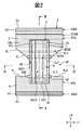
- FIG. 1 is a perspective view of a diaper of a first embodiment according to the present invention.
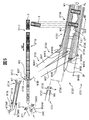
- FIG. 2 is a plan view of the diaper in an unfolded state where a joint portion in a side region is unwound.
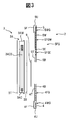
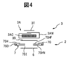
- 3 is a longitudinal sectional view taken along line III-III in FIG. 4 is a cross-sectional view taken along line IV-IV in FIG.
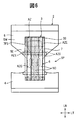
- FIG. 5 is a schematic diagram for explaining a method of manufacturing a diaper.
- 6 is a diagram showing an adhesive application pattern.
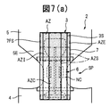
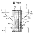
- FIG. 7A and FIG. 7B are diagrams showing another example of the adhesive application pattern.
- FIG. 8 is a developed plan view for explaining a second embodiment according to the present invention.
- 9 is a cross-sectional view taken along line IX-IX in FIG. FIG.
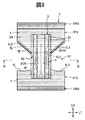
- FIG. 10 is a schematic view for explaining a method of manufacturing the diaper of the second embodiment according to the present invention.
- FIG. 11 is a diagram for explaining a third embodiment according to the present invention.
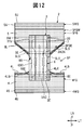
- FIG. 12 is a diagram for explaining a fourth embodiment according to the present invention.
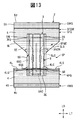
- FIG. 13 is a diagram for explaining a fifth embodiment according to the present invention.
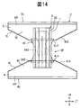
- FIG. 14 is a diagram for explaining a sixth embodiment according to the present invention.
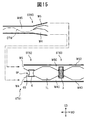
- FIG. 15 is a schematic view for explaining a method of manufacturing the diaper of the sixth embodiment according to the present invention.
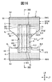
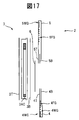
- FIG. 16 is a diagram for explaining a seventh embodiment according to the present invention. 17 is a cross-sectional view taken along line XVII-XVII in FIG.
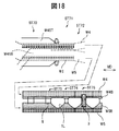
- FIG. 18 is a schematic view for explaining a method of manufacturing the diaper of the seventh embodiment according to the present invention.
- FIG. 19 is a developed plan view for explaining an eighth embodiment according to the present invention.
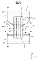
- FIG. 20 is a developed plan view illustrating another example of the end portion
- a diaper 1 includes an exterior body 2 and an interior body 3.
- the exterior body 2 includes a front body 4, a back body 5, and a connecting sheet 6 that are separate from each other.
- the front body 4 and the back body 5 are joined to each other in the side region 1F and connected to each other by a connecting sheet 6 extending in the front-rear direction FR in the crotch region 1C.
- the front body 4 is located on the abdomen side of the wearer
- the back body 5 is located on the back side of the wearer.
- the diaper 1 also includes a waistline or waist hole 1W defined by the upper edge 4U of the front body 4 and the upper edge 5U of the back body 5, and a pair of leg supports or leg holes 1L.
- each leg hole 1L is defined by an edge 1LE, and this edge 1LE is composed of a lower edge 4L of the front body 4, a lower edge 5L of the rear body 5, and both edges 6S of the connecting sheet 6 in the lateral direction LT.
- the interior body 3 includes an absorptive main body, and is fixed to the connection sheet 6 so as to overlap the exterior body 2. Referring to FIG. 2 showing the diaper 1 in the unfolded state, the front body 4 has a rectangular shape.
- the upper edge 4U of the front body 4 extends linearly in the lateral direction LT.
- the lower edge 4L of the front body 4 includes a central portion 4LC in the center of the lateral direction LT and side portions 4LS on both sides of the lateral direction LT of the central portion 4LC.
- the central portion 4LC is substantially in the lateral direction LT.
- the side portion 4LS extends and slightly curves toward the upper edge 4U.
- both side edges 4S of the front body 4 in the horizontal direction LT extend substantially in the vertical direction LN.
- the vertical direction LN is perpendicular to the horizontal direction LT.
- the back body 5 has a hexagonal shape protruding toward the front body 4.
- the back body 5 includes a rectangular waist part 5W and a trapezoidal extension part 5E extending from the waist part 5W toward the front body 4.
- the upper edge of the back body 5, that is, the upper edge 5U of the waistline portion 5W extends substantially in the lateral direction LT.
- the lower edge 5L of the back body 5, that is, the lower edge 5L of the extending portion 5E includes a central portion 5LC at the center in the lateral direction LT and side portions 5LS on both sides of the lateral direction LT of the central portion 5LC.
- the central portion 5LC extends substantially in the lateral direction LT, and the side portion 5LS extends while being inclined toward the upper edge 5U while being inclined with respect to the lateral direction LT.
- both side edges 5S of the back body 5 in the horizontal direction LT extend substantially in the vertical direction LN.
- the front body 4 and the back body 5 are arranged with a separation region SP in the longitudinal direction LN perpendicular to the lateral direction LT.
- the connecting sheet 6 extends in the longitudinal direction LN across the separation region SP at the approximate center of the front body 4 and the back body 5 in the lateral direction LT, and the front body 4 around the lower edge 4L and the rear around the lower edge 5L.
- the body 5 is fixed to the extension portion 5E.
- the connection sheet 6 has a shape in which a constriction is provided at the substantially center in the longitudinal direction LN among both side edges of the rectangle.
- the length and width of the connecting sheet 6 in the horizontal direction LT are shorter than the width of the front body 4 and the back body 5 in the horizontal direction LT, and the length of the connecting sheet 6 in the vertical direction LN is the vertical direction of the interior body 3. It is shorter than the length of LN.
- the side edge 6S of the connecting sheet 6 includes a central portion 6SC that is substantially in the center in the vertical direction LN and end portions 6SE that are on both sides of the central portion 6SC in the vertical direction LN, and the central portion 6SC is curved inward.
- the end portion 6SE extends substantially in the longitudinal direction LN.
- the end portion 6SE does not coincide with the edge of the exterior body 2 that defines the leg hole 1L, that is, the lower edge 4L of the front body 4 and the lower edge 5L of the rear body 5, and is less than these lower edges 4L and 5L.
- the end portion 6SE corresponds to both edges in the lateral direction LT of the portion of the connecting sheet 6 that overlaps the front body 4 and the back body 5.
- both end edges 6E of the connecting sheet 6 in the vertical direction LN extend substantially in the horizontal direction LT.
- the interior body 3 has a rectangular shape extending in the vertical direction LN.
- Both side edges 3S of the inner body 3 in the horizontal direction LT extend substantially in the vertical direction LN, and both end edges 3E of the vertical direction LN extend substantially in the horizontal direction.
- a pair of leak-proof members 7 are provided along both side edges 3 ⁇ / b> S of the interior body 3 on both sides of the interior body 3 in the lateral direction LT.
- a free edge or outer edge 7SO in the lateral direction LN of the leakage preventing member 7 extends in the longitudinal direction LN.
- the interior body 3 is overlaid on the connecting sheet 6 and fixed. In this case, the interior body 3 extends beyond the connection sheet 6 in the longitudinal direction LT and is also fixed to the front body 4 and the back body 5.
- the central portion 6SC of the both side edges 6S of the connecting sheet 6 is inside the lateral direction LT with respect to the outer edge 7SO of the leakage preventing member 7, and moreover than both side edges 3S of the interior body 3.
- the end portions 6SE of the side edges 6S are on the outer side in the lateral direction LT with respect to the side edges 3S of the interior body 3, and further on the outer side in the lateral direction LT with respect to the outer edge 7SO of the leakage preventing member 7. As shown in FIG.
- the front body 4 includes two sheets, that is, a top sheet 4T facing the wearer when worn, and a back sheet 4B facing the outside when worn, and the top sheet 4T and the back sheet. 4B are superimposed on each other.
- the back body 5 also includes two sheets, that is, a top sheet 5T facing the wearer when worn, and a back sheet 5B facing the outside when worn, and the top sheet 5T and the back sheet 5B are overlapped with each other.
- the connecting sheet 6 is composed of one sheet. In this case, the sheet may be liquid permeable or liquid impermeable. In this way, the connecting sheet 6 becomes softer than the front body 4 and the back body 5.
- seat 6 can be selected so that it may become softer than the front body 4 and the back body 5.
- FIG. The degree of softness of the sheet material can be measured by a cantilever method, for example.
- seat 6 is attached to the inner side thru
- the connecting sheet 6 may be attached to the outside of the front body 4 and the back body 5, that is, the back sheets 4B and 5B. Or you may make it the periphery of the both ends of the longitudinal direction LN of the connection sheet
- the top sheets 4T and 5T and the back sheets 4B and 5B of the front body 4 and the back body 5 and the connection sheet 6 are polyolefin fibers such as polypropylene (PP) and polyethylene (PE), polyethylene terephthalate (PET), respectively.
- each of the top sheets 4T and 5T is made of an SMS nonwoven fabric having a basis weight of 15 g / m 2 formed from PP, and each of the back sheets 4B and 5B is formed by a basis weight of 17 g / m 2. It consists spunbonded nonwoven m 2, the connecting sheet 6 is composed of basis weight 15 g / m 2 of an SMS nonwoven fabric formed from PP.
- the front body 4 around the upper edge 4U is provided with an elastic member 4WG
- the front body 4 between the elastic member 4WG and the lower edge 4L is provided with an elastic member 4FG.
- a folded portion 4F in which the back sheet 4B is folded on the top sheet 4T side is provided around the upper edge 4U
- the elastic member 4WG is arranged between the back sheets 4B in the folded portion 4F. Fixed between.
- the elastic member 4FG is fixed between the top sheet 4T and the back sheet 4B.
- an elastic member 5WG is provided on the back body 5 around the upper edge 5U
- an elastic member 5FG is provided on the back body 5 between the elastic member 5WG and the lower edge 5L.
- the elastic member 5WG is fixed between the back sheets 5B at the folded portion 5F.
- the elastic member 5FG is fixed between the top sheet 5T and the back sheet 5B.
- These elastic members 4WG, 4FG, 5WG, and 5FG are, for example, thread-like and attached to the front body 4 and the back body 5 in a state of being stretched in the lateral direction LT.
- the elastic member 5FG includes an elastic member 5FGW provided in the waist part 5W of the back body 5 and an elastic member 5FGE provided in the extension part 5E.
- the elastic member 5FGE is provided so as to overlap the interior body 3 and the leak-proof member 7.
- the elastic member 5FGE provides an elastic action between the side region 1F and the crotch region 1C of the diaper 1 when worn.
- the upper edges of the top sheets 4T and 5T are arranged substantially along the lower edges of the elastic members 4WG and 5WG, and the lower edges of the top sheets 4T and 5T are arranged substantially along the lower edges of the back sheets 4B and 5T.
- the elastic members 4WG, 4FG, 5WG, and 5FG are made of elastic fibers such as natural rubber, synthetic rubber, and spandex, and the expansion ratio is, for example, 1.3 to 3.5 times.
- the thickness of the elastic members 4WG, 4FG, 5WG, and 5FG is, for example, 300 to 1200 dtex.
- the elastic members 4WG and 5WG are each composed of spandex having a thickness of 940 dtex and an expansion ratio of 3.0, and the elastic members 4FG and 5FG are spandex having a thickness of 780 dtex and an expansion ratio of 2.5. Consists of Each of the elastic member 4WG and the elastic member 5WG includes five, the elastic member 4FG includes ten, the elastic member 5FGW of the waistline portion 5W includes eleven, and the elastic member 5FGE of the extension portion 5E includes two spandexes.
- the elastic members 4WG, 4FG, 5WG, and 5FG may be formed of an elastic sheet.
- the interior body 3 includes a liquid-permeable top sheet 3T, a liquid-impermeable back sheet 3B, and an absorber disposed between the top sheet 3T and the back sheet 3B.
- the absorbent body 3A includes an absorbent core 3AC and a wrap sheet 3AW that wraps the absorbent core 3AC.
- a widened portion 3ACW is formed at both ends of the absorbent core 3AC in the longitudinal direction or the longitudinal direction LN and an intermediate portion between both ends, and these widened portions 3ACW are connected to each other by a narrowed portion 3ACN.
- the absorber core 3AC is provided with a plurality of slits 3ACS extending in the longitudinal direction or the longitudinal direction LN.
- These slits 3ACS include a central slit substantially at the center in the lateral direction LT and side slits on both sides of the central slit.
- the central slit is 320 mm long and 12 mm wide
- the side slit is 80 mm long and 10 mm wide. If it does in this way, absorber core 3AC will bend easily along slit 3ACS, and absorber 3A will become easy to stick to a wearer.
- the top sheet 3T is a hydrophilic nonwoven fabric formed from polyolefin fibers, PET fibers, and the like, and is composed of a nonwoven fabric manufactured by a manufacturing method such as spunbonding or air-through.
- the back sheet 3B is composed of a waterproof and moisture permeable film formed of PE or the like.
- the absorbent core 3AC is made of pulp, super absorbent polymer (SAP), a mixture thereof, or the like.
- the wrap sheet 3AW is a hydrophilic nonwoven fabric formed from polyolefin fibers, PET fibers, and the like, and is configured from a nonwoven fabric manufactured by a manufacturing method such as spunbonding or air-through.
- the top sheet 3T is made of a non-woven fabric having a basis weight of 25 g / m 2 manufactured by air-through
- the back sheet 3B is made of a moisture-permeable PE film having a basis weight of 22 g / m 2
- the absorbent core 3AC has a weight of 250 g.
- the wrap sheet 3AW is composed of an SMS non-woven fabric having a basis weight of 13 g / m 2 , from a 1 layer mixture of / m 2 pulp and a basis weight of 200 g / m 2 SAP. As shown in FIG.
- each leak-proof member 7 includes a fixed edge or inner edge 7SI fixed to the exterior body 2 or the interior body 3, and a free edge or outer edge 7SO not fixed to the exterior body 2 or the interior body 3. And have.
- Each leak-proof member 7 includes a liquid-impermeable sheet 7SH and an elastic member 7G, and the liquid-impermeable sheet 7SH includes a leak-proof nonwoven fabric 7SHN and a leak-proof film 7SHF.
- the leakage prevention nonwoven fabric 7SHN is folded and overlapped on the outer edge of the leakage prevention film 7SHF, and the elastic member 7G is fixed between the folded leakage prevention nonwoven fabrics 7SHN. .
- the outer edge of the leak-proof film 7SHF does not reach the outer edge 7SO of the leak-proof member 7.
- the edges of the leakage prevention nonwoven fabric 7SHN and the waterproof film 7SHF are substantially aligned with each other.
- Each leak-proof member 7 rises toward the wearer when worn and acts as a leak-proof wall.
- the leak-proof nonwoven fabric 7SHN is composed of polyolefin fiber, PET fiber, or the like, and is manufactured by a spunbond method or the like.
- the leak-proof film 7SHF is composed of PE, PET, or the like.
- the leak-proof nonwoven fabric 7SHN is composed of a hydrophobic SMS nonwoven fabric having a basis weight of 15 g / m 2
- the leak-proof film 7SHF is composed of a moisture-permeable PE film having a basis weight of 18 g / m 2
- the elastic member 7G is made of an elastic fiber such as natural rubber, synthetic rubber, or spandex.
- the elastic member 7G is composed of two spandex having a thickness of 620 dtex and an expansion ratio of 2.2. These members are connected or fixed by, for example, heat sealing, sonic sealing, adhesive, or the like.
- a hot melt adhesive containing styrene-isoprene-styrene (SIS), styrene-butadiene-styrene (SBS), styrene-ethylene-butylene-styrene (SEBS), or the like can be used.
- HMA hot melt adhesive
- the top sheets 4T and 5T and the back sheets 4B and 5B of the front body 4 and the back body 5 are connected to each other by an HMA previously applied to the elastic members 4WG, 4FG, 5WG, and 5FG.
- the top sheets 4T and 5T and the back sheets 4B and 5B are applied to the top sheets 4T and 5T by a coating method such as spiral or control seam.
- HMA is applied.
- HMA is applied to the top sheets 4T and 4B and the back sheets 5T and 5B around the lower edges 4L and 5L to prevent peeling.
- the connecting sheet 6 is connected to the front body 4 and the back body 5 by a sonic seal, an adhesive, or the like.
- HMA is applied in advance to the back surface of the connecting sheet 6 using a slot coat coating method.
- the top surface and the bottom surface of the absorber core 3AC are connected to the core wrap sheet 3AW by an adhesive such as HMA.
- the adhesive is applied by a coating method such as spiral, slot coat, control seam, bead, curtain coater or the like so as to have a basis weight of 1.5 to 10 g / m 2 .
- HMA is applied by a spiral coating method so that the basis weight is 5 g / m 2 .
- HMA is applied to the back surface 3B of the interior body 3 or the side of the leak-proof member 7 facing the exterior body 2 by a control seam coating method, whereby the interior body 3 and the leak-proof member 7 are connected to the front body. 4.
- HMA is applied to the elastic member 7G by a slit nozzle method
- the elastic member 7G is fixed to the leak-proof nonwoven fabric 7SHN by this HMA.
- the leak-proof nonwoven fabric 7SHN and the leak-proof film 7SHF are joined to each other by applying HMA to the leak-proof nonwoven fabric 7SHN by a spiral coating method.
- the front body 4 around the side edges 4S and the back body 5 around the side edges 5S are joined together by heat sealing, ultrasonic sealing, or the like.
- the edge LE that defines the leg hole 1L includes a side portion 4LS of the lower edge 4L of the front body 4, a side portion 5LS of the lower edge 5L of the rear body 5, and both edges 6S of the connecting sheet 6. .
- the edge 1LE is formed by one cutting action and is smoothly connected and curved.
- at least a part of both side edges 6S of the connecting sheet 6 in the separation region SP between the front body 4 and the back body 5 is both side edges 3S of the interior body 3.
- the movable range of the wearer's leg can be increased while maintaining the absorption surface of the interior body 3 large. That is, it is possible to prevent the wearer's legs from becoming difficult to move while securing the good absorption performance of the interior body 3.
- the end portion 6SE of the connecting sheet 6 is located on the outer side in the lateral direction LT from both side edges 3S of the interior body 3 (FIG. 2). As a result, it is possible to reliably connect the connecting sheet 6 to the front body 4 and the back body 5 while facilitating movement of the wearer's legs.
- the extended part 5E which has the elastic member 5FGE is provided in the back body 5, the shape of the diaper 1 becomes underwear shape and the wearer's buttocks are entirely covered with the back body 5. Therefore, it is possible to suppress leakage, and to reduce anxiety about the wearer's leakage. Furthermore, since the inner body 3 is pulled up toward the side region 1F (FIG. 1) by the elastic member 5FGE, the inner body 3 is prevented from being swung inside, and thus the absorbability of the inner body 3 is maintained. Further, since the edge 1LE that defines the leg hole 1L is smoothly connected and curved, the curved shape follows the wearer's leg and adhesion to the wearer is enhanced.
- connection sheet 6 may be shorter than the length of the interior body 3. Therefore, the quantity of the connection sheet
- seat 6 is comprised from one sheet
- a nonwoven fabric containing rayon, polyolefin fibers and polyester fibers for example, a nonwoven fabric produced by a spunlace method having a basis weight of 26 g / m 2 ), or a nonwoven fabric containing pulp and polyester (eg, spunlace).
- Nonwoven fabric manufactured by the above method and having a basis weight of 40 g / m 2 is used.
- seat 6 it can suppress that the interior body 3 hangs inside. For this reason, the leak-proof member 7 comes to rise reliably toward the wearer. That is, the connecting sheet 6 provides a starting point for the leakage preventing member 7 to rise toward the wearer.
- the manufacturing method of the diaper 1 of 1st Example by this invention includes a step ST ⁇ b> 1 for manufacturing the interior body 3 including the leak-proof member 7, a step ST ⁇ b> 2 for manufacturing the connecting sheet 6, and a continuum of the diaper 1. And a step ST3 of manufacturing the diaper web W1.
- step ST1 first, the absorbent core 3AC in which the slit 3ACS is formed in advance is wrapped by a wrap sheet web W3AW, which is a continuous body of the wrap sheet 3AW (ST11). In this case, the absorber core 3AC is transported so that the slit 3ACS is parallel to the transport direction MD.
- top sheet web W3T and the back sheet web W3B which are continuous bodies of the top sheet 3T and the back sheet 3B, are respectively attached to the upper surface and the lower surface of the wrap sheet web W3AW that wraps the absorbent core 3AC.
- the interior body web W3 which is a continuous body is formed (ST12).
- a continuous elastic body W7G which is a continuum of a leakproof non-woven web W7SHN, which is a continuous body of two leakproof nonwoven fabrics 7SHN, and a leakproof film web W7SHF, which is a continuous body of two leakproof films 7SHF, and an elastic member 7G. are attached (ST13).
- the leak-proof nonwoven fabric web W7SHN is divided along the conveyance direction MD to form a leak-proof member web W7 that is a continuous body of the leak-proof member 7 (ST14).
- each leakage preventing member web W7 is attached to the back surface of the interior body web W3, that is, the back sheet web W3B (ST15).
- the HMA is applied in a predetermined pattern to the back surfaces of the interior body web W3 and the leakage preventing member web W7, that is, the surface facing the exterior body web W2 (ST16).
- the interior body web W3 and the leakage preventing member web W7 are cut into a length corresponding to one product, and the interior body 3 including the leakage preventing member 7 is formed (ST17).
- step ST2 HMA is applied to the bottom surface of the connection sheet web W6 that is a continuous body of the connection sheets 6 (ST21).
- step ST22 the connecting sheet web W6 is cut into one product to form the connecting sheet 6 (ST22).
- step ST3 the top sheet web W45T is divided along the conveying direction MD, and a top sheet web W4T that is a continuous body of the top sheet 4T of the front body 4 and a top sheet that is a continuous body of the top sheet 5T of the back body 5.
- a web W5T is formed (ST31).
- the back sheet web W45B is divided along the conveyance direction MD, and the back sheet web W4B, which is a continuous body of the back sheet 4B of the front body 4, and the back sheet web, which is a continuous body of the back sheet 5B of the back body 5.
- W5B is formed (ST32).
- the top sheet web W4T and the back sheet web W5B are conveyed along the conveyance direction MD with a separation area SP in a direction CD substantially orthogonal to the conveyance direction MD.
- the back elastic webs W4B and W5WG which are continuous bodies of the elastic members 4WG and 5WG, and the continuous elastic bodies W4FG and W5FG which are continuous bodies of the elastic members 4FG and 5FG are respectively stretched in the conveying direction MD.
- the connecting sheet 6 is attached to the front body web W4 and the back body web W5 at intervals in the transport direction MD so as to straddle the separation region SP, and thereby the exterior body web that is a continuous body of the exterior body 2 W2 is formed (ST36).
- the connecting sheet 6 is first attached to the top sheet webs W4T and W5T, Next, the back sheet webs W4B and W5B are superimposed on the connecting sheet 6 and the top sheet webs W4T and W5T.
- the connecting sheet 6 is first attached to the backsheet webs W4B and W5B, and then the topsheet webs W4T and W5T are superimposed on the connecting sheet 6 and the backsheet webs W4B and W5B.
- the exterior body web W2 is cut at an interval in the transport direction MD (ST37).
- both side edges 6S of the connection sheet 6 are curved inward, or at least a part of both side edges 6S of the connection sheet 6 in the separation region SP is more lateral in the lateral direction LT than both side edges 3S of the interior body 3.
- the connecting sheet 6 is cut so as to be inside.
- the cutting action is performed once, for example, along the annular cutting line CT.
- the interior body 3 provided with the leakage preventing member 7 is attached to the front body web W4, the back body web W5, and the connecting sheet 6 to form the diaper web W1 (ST38).
- the diaper web W1 is folded along a fold line FL along the conveyance direction MD (not shown).
- the fold line FL may be the center in the orthogonal direction CD of the diaper web W1, or may be offset from the center.
- the front body web W4 and the back body web W5 are partially joined at intervals in the transport direction MD, thereby forming a joined portion.
- the diaper web 1 is cut in the orthogonal direction CD at these joint portions, thereby forming the diaper 1 (not shown).
- the cutting action for forming the edge 1LE that defines the leg hole 1L is performed.
- the outer body web W2, that is, the front body web W4 and the back body web W5 connected to each other by the connection sheet 6 can be cut in a state in which wrinkles are eliminated by pulling outward in the orthogonal direction CD. It becomes. Therefore, the leg hole 1L can be formed in a regular shape.
- the front body web W4 and the back body web W5 that are not connected to each other by the connection sheet 6 may be wrinkled. If the cutting action is performed in this state, the edge 1LE that defines the leg hole 1L is formed. There is a risk of deviating from the regular shape. In addition, it is difficult to securely attach the interior body 3 to the exterior body web W2 in this state. On the other hand, when the cutting action is performed, the front body web W4 and the back body web W5 around the edge 1LE defining the leg hole 1L are discontinuous in the transport direction MD.
- the connecting sheet 6 or the interior body 3 is attached to the front body web W4 and the back body web W5 in which wrinkles or tackle are generated, the connection sheet 6 or the interior body 3 is securely connected to the front body web W4 and the back body web W5. Therefore, the productivity of the diaper 1 may be reduced.
- a cutting action for forming the edge 1LE is performed, and the interior body 3 is formed. It is attached. Therefore, the above problems do not occur.
- seat 6 is not attached to the front body web W4 and the back body web W5 in the form of a web, but is attached intermittently after cut
- FIG. 20 shows a case where the connecting sheet web W6 is attached to the front body web W4 and the back body web W5. In this case, the end portion 6SE ′ on the back body 5 side is aligned with the side portion 5LS.
- the connecting sheet 6 there is a connecting sheet 6 around the side portion 5LS. Further, a portion 6 ′ of the connecting sheet 6 that overlaps the front body 4 extends along the side portion 4LS to the side edge 4S of the front body 4, and thus the connecting sheet 6 exists around the side portion 4LS. As a result, the side portions 4LS and 5LS are relatively hard, and there is a possibility that the wearer's leg may feel uncomfortable.
- the end portion 6SE is located inside the lateral direction LT with respect to the side portions 4LS and 5LS, so that the above-described problems do not occur. And since the area of the connection sheet
- FIG. 6 shows an adhesive application pattern in step ST16.
- the width of the region AZ to which the adhesive is applied varies along the vertical direction LN. That is, the adhesive application area AZ includes both end areas AZE in the vertical direction LN, and a central area AZC in the center in the vertical direction LN, and an intermediate area AZI between the end area AZ on the back body 5 side and the central area AZC. .
- both end regions AZ and the intermediate region AZI do not overlap with the connecting sheet 6, and the central region AZC overlaps with the connecting sheet 6.
- the width of both end regions AZE is substantially the same as the entire width of the interior body 3 and the leak-proof member 7 and is the widest. This is to prevent the inner body 3 and the leak-proof member 7 from being peeled off from the front body 4 and the back body 5 and to eliminate the feeling of discomfort.
- the width of the central region AZC is narrower than the width of the interior body 3 and is the narrowest. In the first embodiment according to the present invention, the width of the central region AZC is about 90 mm.
- the width of the intermediate area AZI is between the width of the both end areas AZ and the width of the central area AZC.
- a non-fixed region NC is formed on both sides of the central region AZC and the intermediate region AZI in the lateral direction LT, and thus the inner body 3 and the leakage preventing member 7 are not fixed to the outer body 2. become.
- the width of the non-fixed area NC around the central area AZC is larger than the width of the non-fixed area NC around the intermediate area AZI.
- the non-fixed region NC is also formed at the center in the lateral direction LT of the central portion AZC.
- the exterior body 2 that is, the portion around both edges 6S of the connecting sheet 6 and the interior body 3 are not fixed to each other. Therefore, the interior body 3 is easily deformed according to the body shape of the wearer, and the adhesion of the interior body 3 is enhanced.
- the leakage preventing member 7 rises starting from the lateral side edges AZS of the central region AZC and the intermediate region AZI. Therefore, around the central region AZC, the rising amount of the leakage preventing member 7 can be increased by increasing the non-fixed region NC. Moreover, the adhesiveness to the wearer of the interior body 3 is also improved.
- the non-fixed area NC is made smaller around the intermediate area AZI, and therefore the rise of the leakage preventing member 7 is suppressed.
- the leakage preventing member 7 is prevented from rising excessively and covering the absorption surface of the interior body 3.
- the intermediate region AZI is provided on the back body 5 side, that is, on the wearer's buttocks side, the leak-proof member 7 is prevented from being difficult to break in the buttocks and the wearing feeling is enhanced.
- step ST16 (FIG. 5) when an adhesive is applied to the conveyance direction MD of the interior body web W3 and the leakage preventing member web W7, the above-described patterning can be easily performed. Note that, as shown in FIG.
- the width of the intermediate region AZI may substantially coincide with the entire width of the interior body 3 and the leakage preventing member 7. Also in this case, excessive twisting of the leakage preventing member 7 can be prevented.
- the center non-fixed area NC in the lateral direction LT is omitted.
- a non-fixed region NC may be provided adjacent to both end regions AZE. If it does in this way, it will be suppressed that a wrinkle is caused to interior 3. As a result, the feeling of wearing is enhanced, and the stable absorption performance of the interior body 3 is maintained.
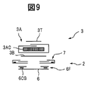
- 8 and 9 show a second embodiment according to the present invention. The difference from the first embodiment according to the present invention will be described.
- the elastic member 5LG is intermittently provided along the lower edge 5L of the back body 5. That is, the elastic member 5LG is provided along the side portion 5LS of the lower edge 5L, but is not provided along the central portion 5LC.
- the elastic member 5LG provides an elastic action between the side region 1F and the crotch region 1C of the diaper 1. As a result, the interior body 3 is further pulled up toward the side region 1F. In addition, the adhesion is improved in the leg hole 1L. In addition, you may abbreviate
- an elastic member 6CG is provided adjacent to both side edges 6S of the connecting sheet 6.
- the elastic member 6CG is attached to the connecting sheet 6 in a state of being stretched in the vertical direction LN.
- a folded portion 6F in which the connecting sheet 6 is folded is provided, and the elastic member 6CG is fixed to the connecting sheet 6 at the folded portion 6F.
- the elastic members 5LG and 6CG can be configured similarly to the above-described elastic members.
- the elastic members 5LG and 6CG are each composed of spandex having a thickness of 620 dtex and an expansion ratio of 2.2.
- FIG. 10 shows the manufacturing method of the second embodiment according to the present invention.
- a continuous elastic body W6CG which is a continuous body of elastic members 6CG, is attached to the connection sheet web W6 (ST40), and the connection sheet web W6 is folded. Overlapping portion 6F is formed (ST41). Next, on both sides of the connecting sheet web W6, a cutting action is performed at intervals in the transport direction MD, and side edges 6S curved inward are formed (ST42). Next, an adhesive is applied to the surface of the connecting sheet web W6 that faces the interior body web W3 and the leakage preventing member web W7 (ST43). In this case, the adhesive is applied with the application pattern shown in FIG. 6, FIG. 7 (a), and FIG. 7 (b).
- the connecting sheet web W6 is attached to the interior body web W3 and the leakage preventing member web W7 (ST44).
- an adhesive is applied to the back surface of the connecting sheet web W6, that is, the surface facing the exterior body web W2 (ST45).
- the connecting sheet web W6 is cut together with the interior body web W3 and the leakage preventing member web W7 (ST17 ′).
- an adhesive for fixing the continuous elastic body W5LG which is a continuous body of the elastic member 5LG, is applied to the backsheet web W5B of the back body web W5 (ST50).
- the continuous elastic body W5LG is attached to the back seat web W5B at substantially the same position as the continuous elastic bodies W4FG and W5FG (ST51).
- the continuous elastic body W5LG is supplied while being swung in the orthogonal direction CD.
- the top sheet webs W4T and W5T are overlapped to form the front body web W4 and the back body web W5 (ST34 ').
- the continuous elastic body W5LG that protrudes into the separation region SP is held by the pair of belts and cut and removed (ST52). In this way, the intermittent elastic member 5LG is formed.
- seat 6 is first attached to the interior body 3, and is then attached to the exterior body 2.
- FIG. 11 shows a third embodiment according to the present invention.
- the elastic member 5LG is provided not continuously but continuously. That is, the elastic member 5LG is provided along the side portion 5LS and the central portion 5LC of the lower edge 5L. As a result, the elastic member 5LG overlaps the interior body 3, so that the interior body 3 is further brought into close contact with the wearer.
- the continuous elastic body W5LG is swung without protruding from the back body web W5 (see ST51).
- FIG. 12 shows a fourth embodiment according to the present invention.
- the elastic member 4LG is provided along the lower edge 4L of the front body 4 in the same manner as the elastic member 5LG of the back body 5.
- the inner body 3 is pulled up toward the side region 1F on the abdomen side of the wearer, and the displacement of the inner body 3 is further suppressed.
- These elastic members 4LT and 5LG may be intermittent as shown in FIG. 12, or may be continuous.
- the elastic member 4LG of the front body 4 is provided intermittently, that is, if the elastic member 4LG does not overlap with the interior body 3 or the connecting sheet 6, the width of the interior body 3 on the abdomen side is suppressed. The Therefore, it is particularly preferable when the wearer is a male.
- the elastic member 4LG continuously if elastic member 4LG is provided adjacent to a woman's excretion opening, the adhesion nature of interior body 3 will be raised.
- the elastic member 4LG is provided so as to pass below the male genitals, a space can be formed in the diaper 1, and thus the wearing feeling of the male wearer is enhanced.
- the elastic member 4LG can be attached in the same manner as the elastic member 5LG.
- FIG. 13 shows a fifth embodiment according to the present invention.
- the front body 4 is provided with the elastic member 4LG, and the back body 5 is not provided with the elastic member 5LG.
- the elastic member 4LT may be intermittent or continuous.
- 14 and 15 show a sixth embodiment according to the present invention.
- the front body 4 and the back body 5 have substantially the same shape. That is, the front body 4 includes a rectangular waistline portion 4W and a trapezoidal extension portion 4E extending from the waistline portion 4W toward the back body 5, and the back body 5 has a rectangular waistline portion 5W.
- the lower edge 4L of the front body 4 that is, the lower edge 4L of the extended portion 4E includes a central portion 4LC at the center in the lateral direction LT and side portions 4LS on both sides of the lateral direction LT of the central portion 4LC.
- 4LC extends substantially in the lateral direction LT
- the side portion 4LS extends linearly toward the upper edge 4U and inclined with respect to the lateral direction LT.
- the lower edge 5L of the back body 5, that is, the lower edge 5L of the extending portion 5E includes a central portion 5LC at the center in the lateral direction LT and side portions 5LS on both sides of the lateral direction LT of the central portion 5LC.
- connection sheet 6 is fixed to the front body 4 around the central portion 4LC and the back body 5 around the central portion 5LC.
- the sheet web W45 formed by laminating the top sheet web W45T and the backsheet web W45B to each other is swung in the orthogonal direction CD while being conveyed in the conveyance direction MD. Cut along the moving cutting line CTW to form the front body web W4 and the back body web W5 (ST60).
- the front body 4 and the back body 5 respectively have convex portions W4C and W5C and concave portions W4D and W5D that are alternately continuous.
- the convex portions W4C and W5C correspond to the extended portions 4E and 5E.
- the convex portions W4C, W5C and the concave portions W4D, W5D of the front body web W4 and the back body web W5 are aligned with each other (ST61).
- a separation region SP is formed between the convex portions W4C and W5C (see Japanese Patent No. 3916878).
- the connecting sheet 6 is connected to the front body web W4 and the back body web W5 to form the outer package web W2 (ST62).
- the side edge 6S of the connection sheet 6 is cut in advance so that the connection sheet 6 has a constriction.
- the inner body 3 is attached to the outer body web W2 (ST63).
- the edge 1LE that defines the leg hole 1L is formed without requiring a cutting action, so that trim loss is greatly reduced.
- 16 to 18 show a seventh embodiment according to the present invention.
- the top sheets 4T and 5T are comprised from a non-stretchable nonwoven fabric
- the back sheets 4B and 5B are comprised from a stretchable sheet.
- the stretchable sheet for example, a stretchable nonwoven fabric containing stretchable thermoplastic fibers and elastomer fibers can be used.
- the thermoplastic fiber for example, polyolefin fibers such as polypropylene and polyethylene, and polyester fibers such as polyethylene terephthalate and polybutylene terephthalate can be used.
- the elastomer fiber for example, urethane-based, polystyrene-based, rubber-based fibers such as polyurethane can be used.
- the stretchable nonwoven fabric can be produced by a production method such as spunbond or air-through. The stretchable nonwoven fabric is used after being subjected to gear stretching and exhibiting stretchability in the transport direction MD.
- the back sheets 4B and 5B formed of the elastic sheet provide an elastic action between the side region 1F and the crotch region 1C of the diaper 1.
- the stretchable sheet may be provided continuously in the conveyance direction MD or may be provided intermittently. Moreover, it can also be provided in one or both of the front body 4 and the back body 5.
- the back sheet web W45B is bonded to the top sheet web W45T in a state of being stretched in the conveying direction MD (ST70).
- the continuous elastic bodies W4WG, W5WG, W4FG, and W5FG to which the adhesive is applied have already been supplied up to the top sheet web W45T.
- the top sheet web W45T is folded back and overlapped with the back sheet web W45B at both side edges in the transport direction MD (ST71).
- an integrated web WI in which the top sheet web W45T, the back sheet web W45B, and the continuous elastic bodies W4WG, W5WG, W4FG, and W5FG are integrated is formed.
- the integrated web WI is divided into a front body web W4 and a back body web W5 (ST72).
- the connecting sheet 6 is connected to the front body web W4 and the back body web W5 (ST73), and an edge 1LE that defines the leg hole 1L is formed (ST74).
- the interior body 3 is attached (ST75).
- the backsheet web W45B contracts in the orthogonal direction CD when extended in the conveying direction MD, a position controller is provided in front of each processing location, and the orthogonal direction of the integrated web WI, front body web W4, and back body web W5.
- the CD width is maintained at a normal value.
- the front body 4 and the back body 5 are formed of a stretchable sheet and a non-stretchable nonwoven fabric that overlap each other.
- at least a part of the front body 4 or the back body 5, for example, a part around the leg hole 1L can be formed only from the stretchable sheet.
- only the stretchable sheet is composed of one or a plurality of stretchable sheets.
- the basis weight of the part is preferably 50 g / m 2 or more, for example, 80 g / m 2 .
- the stretchability of the front body 4 or the back body 5 is improved, that is, the maximum stretch dimension of the front body 4 or the back body 5 is increased, or the stretchability in the longitudinal direction LN of the diaper 1 (see FIG. 2). I get out.
- the front body 4 or the back body 5 fits around the leg of the wearer around the leg hole 1L, and the wearing feeling is improved.
- FIG. 19 shows an eighth embodiment according to the present invention.
- the connecting sheet 6 has a rectangular shape with no constriction, and therefore the entire side edges 6S of the connecting sheet 6 are inside the lateral direction LT from the side edges 3S of the interior body 3. In this way, the leg of the wearer becomes easier to move.
- Such a shape of the connecting sheet 6 can be obtained by performing a cutting action (ST37 in FIG. 5) for forming the edge 1LE that defines the leg hole 1L so that the connecting sheet 6 is not cut.
- a cutting action ST37 in FIG. 5
- the load of the cutting blade used in the cutting action can be reduced, and therefore the life of the cutting blade can be reduced. Can be extended.
- the embodiments described so far can also be combined with each other.
Abstract
Description
図2 脇領域での接合部分を解いた展開状態にあるおむつの平面図である。
図3 図2の線III−IIIに沿ってみた縦断面図である。
図4 図2の線IV−IVに沿ってみた横断面図である。
図5 おむつの製造方法を説明する概略図である。
図6 接着剤適用パターンを示す図である。
図7(a)及び7図(b) 接着剤適用パターンの別の例を示す図である。
図8 本発明による第2実施例を説明する展開平面図である。
図9 図8の線IX−IXに沿ってみた横断面図である。
図10 本発明による第2実施例のおむつの製造方法を説明する概略図である。
図11 本発明による第3実施例を説明する図である。
図12 本発明による第4実施例を説明する図である。
図13 本発明による第5実施例を説明する図である。
図14 本発明による第6実施例を説明する図である。
図15 本発明による第6実施例のおむつの製造方法を説明する概略図である。
図16 本発明による第7実施例を説明する図である。
図17 図16の線XVII−XVIIに沿ってみた断面図である。
図18 本発明による第7実施例のおむつの製造方法を説明する概略図である。
図19 本発明による第8実施例を説明する展開平面図である。
図20 端部分の別の例を説明する展開平面図である。 FIG. 1 is a perspective view of a diaper of a first embodiment according to the present invention.
FIG. 2 is a plan view of the diaper in an unfolded state where a joint portion in a side region is unwound.
3 is a longitudinal sectional view taken along line III-III in FIG.
4 is a cross-sectional view taken along line IV-IV in FIG.
FIG. 5 is a schematic diagram for explaining a method of manufacturing a diaper.
6 is a diagram showing an adhesive application pattern.
FIG. 7A and FIG. 7B are diagrams showing another example of the adhesive application pattern.
FIG. 8 is a developed plan view for explaining a second embodiment according to the present invention.
9 is a cross-sectional view taken along line IX-IX in FIG.
FIG. 10 is a schematic view for explaining a method of manufacturing the diaper of the second embodiment according to the present invention.
FIG. 11 is a diagram for explaining a third embodiment according to the present invention.
FIG. 12 is a diagram for explaining a fourth embodiment according to the present invention.
FIG. 13 is a diagram for explaining a fifth embodiment according to the present invention.
FIG. 14 is a diagram for explaining a sixth embodiment according to the present invention.
FIG. 15 is a schematic view for explaining a method of manufacturing the diaper of the sixth embodiment according to the present invention.
FIG. 16 is a diagram for explaining a seventh embodiment according to the present invention.
17 is a cross-sectional view taken along line XVII-XVII in FIG.
FIG. 18 is a schematic view for explaining a method of manufacturing the diaper of the seventh embodiment according to the present invention.
FIG. 19 is a developed plan view for explaining an eighth embodiment according to the present invention.
FIG. 20 is a developed plan view illustrating another example of the end portion.
本発明による第1実施例を示す図1を参照すると,おむつ1は外装体2及び内装体3を具備する。
外装体2は、互いに別個の前身頃4、後身頃5及び連結シート6を備える。前身頃4及び後身頃5は、脇領域1Fにおいて互いに接合されると共に、股領域1Cにおいて前後方向FRに延びる連結シート6によって互いに連結される。ここで、着用状態において、前身頃4は装着者の腹側に位置し、後身頃5は装着者の背側に位置する。また、おむつ1は、前身頃4の上縁4U及び後身頃5の上縁5Uによって画定された胴刳りないしウエストホール1Wと、一対の脚刳りないしレッグホール1Lとを備える。この場合、各レッグホール1Lは縁1LEによって画定され、この縁1LEは、前身頃4の下縁4L、後身頃5の下縁5L、及び連結シート6の横方向LTの両縁6Sから構成される。一方、内装体3は、吸収性本体を含み、外装体2の内側において連結シート6に重ねて固定される。
展開状態にあるおむつ1を示す図2を参照すると、前身頃4は長方形状をなしている。前身頃4の上縁4Uは横方向LTに直線状に延びる。一方、前身頃4の下縁4Lは、横方向LTのほぼ中央の中央部分4LCと、中央部分4LCの横方向LTの両側の側方部分4LSとを備え、中央部分4LCはほぼ横方向LTに延び、側方部分4LSは上縁4Uに向けてわずかに湾曲する。また、前身頃4の横方向LTの両側縁4Sはほぼ縦方向LNに延びる。ここで、縦方向LNは横方向LTに垂直である。
また、後身頃5は前身頃4に向けて突出する六角形状をなしている。すなわち、後身頃5は、長方形状の胴回り部分5Wと、胴回り部分5Wから前身頃4に向けて延出する台形状の延出部分5Eとを備える。後身頃5の上縁すなわち胴回り部分5Wの上縁5Uはほぼ横方向LTに延びる。一方、後身頃5の下縁すなわち延出部分5Eの下縁5Lは、横方向LTのほぼ中央の中央部分5LCと、中央部分5LCの横方向LTの両側にある側方部分5LSとを備え、中央部分5LCはほぼ横方向LTに延び、側方部分5LSは上縁5Uに向けて湾曲しつつ横方向LTに対し傾斜して延びる。また、後身頃5の横方向LTの両側縁5Sはほぼ縦方向LNに延びる。
図2に示される展開状態において、前身頃4及び後身頃5は、横方向LTに垂直な縦方向LNに離間領域SPを隔てて配置される。連結シート6は、前身頃4及び後身頃5の横方向LTのほぼ中央において、この離間領域SPを横切って縦方向LNに延び、下縁4L周りの前身頃4と、下縁5L周りの後身頃5すなわち延出部分5Eとにそれぞれ固定される。
連結シート6は、長方形の両側縁のうち縦方向LNのほぼ中央にくびれを設けた形状をなしている。この場合、連結シート6の横方向LTの長さないし幅は前身頃4及び後身頃5の横方向LTの幅よりも短く、連結シート6の縦方向LNの長さは内装体3の縦方向LNの長さよりも短い。また、連結シート6の側縁6Sは、縦方向LNのほぼ中央の中央部分6SCと、中央部分6SCの縦方向LNの両側にある端部分6SEとを備え、中央部分6SCは内向きに湾曲し、端部分6SEはほぼ縦方向LNに延びる。言い換えると、端部分6SEは、レッグホール1Lを画定する外装体2の縁、すなわち前身頃4の下縁4Lの及び後身頃5の下縁5Lと一致せず、これら下縁4L,5Lよりも横方向LTの内側にある。なお、端部分6SEは、連結シート6のうち前身頃4及び後身頃5と重なっている部分の横方向LTの両縁に相当する。また、連結シート6の縦方向LNの両端縁6Eはほぼ横方向LTに延びる。
一方、内装体3は縦方向LNに延びる長方形状をなしている。内装体3の横方向LTの両側縁3Sはほぼ縦方向LNに延び、縦方向LNの両端縁3Eはほぼ横方向に延びる。
また、内装体3の横方向LTの両側には、内装体3の両側縁3Sに沿って一対の防漏部材7が設けられる。防漏部材7の横方向LNの自由縁ないし外縁7SOは縦方向LNに延びる。
上述したように、内装体3は連結シート6に重ねられ、固定される。この場合、内装体3は縦方向LTに連結シート6を越えて延び、前身頃4及び後身頃5にも固定される。
また、この場合、連結シート6の両側縁6Sの中央部分6SCの少なくとも一部は、防漏部材7の外縁7SOよりも横方向LTの内側にあり、更に、内装体3の両側縁3Sよりも横方向LTの内側にある。これに対し、両側縁6Sの端部分6SEは内装体3の両側縁3Sよりも横方向LTの外側にあり、更に、防漏部材7の外縁7SOよりも横方向LTの外側にある。
図3に示されるように、前身頃4は2枚のシート、すなわち着用時に装着者に面するトップシート4Tと、着用時に外部に面するバックシート4Bとを備え、これらトップシート4T及びバックシート4Bは互いに重ね合わされる。同様に、後身頃5も2枚のシート、すなわち着用時に装着者に面するトップシート5Tと、着用時に外部に面するバックシート5Bとを備え、これらトップシート5T及びバックシート5Bは互いに重ね合わされる。
一方、連結シート6は1枚のシートから構成される。この場合のシートは液透過性であってもよいし液不透過性であってもよい。
このようにすると、連結シート6が前身頃4及び後身頃5よりも柔らかくなる。なお、前身頃4及び後身頃5よりも柔らかくなるように、連結シート6を構成するシートの枚数、材質、目付などを選択することができる。シート材の柔らかさの程度は例えばカンチレバー法により測定することができる。
また、図2に示される例では、連結シート6は前身頃4及び後身頃5の内側ないし装着者側、すなわちトップシート4T,5Tに取り付けられる。しかしながら、連結シート6を前身頃4及び後身頃5の外側、すなわちバックシート4B,5Bに取り付けてもよい。あるいは、連結シート6の縦方向LNの両端周りがトップシート4T,5T及びバックシート4B,5B間に挟まれるようにしてもよい。このようにすると、連結シート6の縦方向LNの両端周りがトップシート4T,5T側又はバックシート4B,5B側に露出せず、肌触りがよくなる。また、連結シート6が前身頃4及び後身頃5から離脱しにくくなる。
ここで、前身頃4及び後身頃5のトップシート4T,5T及びバックシート4B,5B、並びに連結シート6はそれぞれ、ポリプロピレン(PP),ポリエチレン(PE)のようなポリオレフィン系繊維,ポリエチレンテレフタレート(PET)系繊維といった合成繊維から形成される不織布であって、スパンボンド、エアスルーなどの製法によって製造される不織布から構成され、それぞれの目付は例えば13から30g/m2である。本発明による第1実施例において、トップシート4T,5Tはそれぞれ、PPから形成された目付15g/m2のSMS不織布から構成され、バックシート4B,5Bはそれぞれ、PPから形成された目付17g/m2のスパンボンド不織布から構成され、連結シート6はPPから形成された目付15g/m2のSMS不織布から構成される。
また、上縁4U周りの前身頃4には弾性部材4WGが設けられており,弾性部材4WGと下縁4Lとの間の前身頃4には弾性部材4FGが設けられている。図3に示されるように、上縁4U周りにはバックシート4Bがトップシート4T側に折り重ねられた折り重ね部分4Fが設けられており、弾性部材4WGは折り重ね部分4Fにおいてバックシート4B同士間に固定される。一方、弾性部材4FGはトップシート4T及びバックシート4B間に固定される。
同様に、上縁5U周りの後身頃5には弾性部材5WGが設けられており、弾性部材5WGと下縁5Lとの間の後身頃5には弾性部材5FGが設けられる。上縁5U周りにはバックシート5Bがトップシート5T側に折り重ねられた折り重ね部分5Fが設けられており、弾性部材5WGは折り重ね部分5Fにおいてバックシート5B同士間に固定される。一方、弾性部材5FGはトップシート5T及びバックシート5B間に固定される。これら弾性部材4WG,4FG,5WG,5FGは例えば糸状をなし、横方向LTに伸長された状態で前身頃4及び後身頃5に取り付けられる。
この場合、弾性部材5FGは、後身頃5の胴回り部分5Wに設けられた弾性部材5FGWと、延出部分5Eに設けられた弾性部材5FGEとを含む。図2からわかるように、弾性部材5FGEは内装体3及び防漏部材7と重なって設けられる。この弾性部材5FGEは着用時に、おむつ1の脇領域1Fと股領域1Cとの間に弾性作用を提供する。
なお、トップシート4T,5Tの上縁は弾性部材4WG,5WGの下縁に概ね沿って配置され、トップシート4T,5Tの下縁はバックシート4B,5Tの下縁に概ね沿って配置される。
ここで、弾性部材4WG,4FG,5WG,5FGは、天然ゴム、合成ゴム、スパンデックスのような弾性繊維から構成され、伸長倍率は例えば1.3から3.5倍である。弾性部材4WG,4FG,5WG,5FGをスパンデックスから構成した場合、弾性部材4WG,4FG,5WG,5FGの太さは例えば300から1200dtexである。本発明による第1実施例において、弾性部材4WG,5WGは太さ940dtexで伸張倍率3.0倍のスパンデックスからそれぞれ構成され、弾性部材4FG,5FGは太さ780dtexで伸張倍率2.5倍のスパンデックスから構成される。また、弾性部材4WG及び弾性部材5WGはそれぞれ5本、弾性部材4FGは10本、胴回り部分5Wの弾性部材5FGWは11本、延出部分5Eの弾性部材5FGEは2本のスパンデックスを含む。なお、弾性部材4WG,4FG,5WG,5FGを弾性シートから構成してもよい。
図3及び図4に示されるように、内装体3は、液透過性のトップシート3Tと、液不透過性のバックシート3Bと、これらトップシート3T及びバックシート3B間に配置された吸収体3Aとを備えている。また、吸収体3Aは、吸収性コア3ACと、吸収性コア3ACを包むラップシート3AWとを備えている。
吸収体コア3ACの長手方向ないし縦方向LNの両端と、両端間の中間部分とには、拡幅部分3ACWが形成されており、これら拡幅部分3ACWは挟幅部分3ACNによって互いに連結されている。
また、吸収体コア3ACには、長手方向ないし縦方向LNに延びる複数のスリット3ACSが設けられている。これらスリット3ACSは横方向LTのほぼ中央にある中央スリットと、中央スリットの両側にある側方スリットとを含む。本発明による第1実施例において、中央スリットは長さ320mm、幅12mmであり、側方スリットは長さ80mm、幅10mmである。このようにすると、吸収体コア3ACがスリット3ACSに沿って容易に折れ曲がるようになり、吸収体3Aが装着者に密着しやすくなる。
ここで、トップシート3Tは、ポリオレフィン系繊維、PET繊維などから形成される親水性不織布であって、スパンボンド、エアスルーなどの製法によって製造される不織布から構成される。バックシート3Bは、PEなどから形成される防水性かつ透湿性フィルムから構成される。吸収体コア3ACはパルプ、高吸収性ポリマ(SAP)、これらの混合物などから構成される。ラップシート3AWは、ポリオレフィン系繊維、PET繊維などから形成される親水性不織布であって、スパンボンド、エアスルーなどの製法によって製造される不織布から構成される。本発明による第1実施例では、トップシート3Tはエアスルーにより製造された目付25g/m2の不織布から、バックシート3Bは目付22g/m2の透湿性PEフィルムから、吸収体コア3ACは目付250g/m2のパルプ及び目付200g/m2のSAPの混合物1層から、ラップシート3AWは目付13g/m2のSMS不織布から、それぞれ構成される。
図4に示されるように、各防漏部材7は、外装体2又は内装体3に固定された固定縁ないし内縁7SIと、外装体2又は内装体3に固定されていない自由縁ないし外縁7SOとを有する。また、各防漏部材7は液不透過性シート7SH及び弾性部材7Gを含み、液不透過性シート7SHは防漏不織布7SHN及び防漏フィルム7SHFを含む。各防漏部材7の外縁7SOでは、防漏不織布7SHNが折り重ねられて防漏フィルム7SHFの外縁に重ねられておリ、折り重ねられた防漏不織布7SHN同士間に弾性部材7Gが固定される。なお、防漏フィルム7SHFの外縁は防漏部材7の外縁7SOに達していない。一方、各防漏部材7の内縁7SIでは、防漏不織布7SHN及び防水フィルム7SHFの縁が互いにほぼ整列される。
各防漏部材7は着用時に、装着者に向けて立ち上がり、防漏壁として作用する。
ここで、防漏不織布7SHNは、ポリオレフィン系繊維、PET繊維などから構成され、スパンボンド法などによって製造される。防漏フィルム7SHFは、PE,PETなどから構成される。本発明による第1実施例では、防漏不織布7SHNは目付15g/m2の疎水性SMS不織布から構成され、防漏フィルム7SHFは目付18g/m2の透湿性PEフィルムから構成される。弾性部材7Gは、天然ゴム、合成ゴム、スパンデックスのような弾性繊維から構成される。本発明による第1実施例では、弾性部材7Gは太さ620dtexで伸張倍率2.2倍のスパンデックス2本から構成される。
これら部材同士の連結ないし固定は、例えばヒートシール、ソニックシール、接着剤などによって行われる。接着剤として、スチレン−イソプレン−スチレン(SIS),スチレン−ブタジエン−スチレン(SBS),スチレン−エチレン−ブチレン−スチレン(SEBS)などを含むホットメルト接着剤(HMA)を用いることができる。
具体的には、前身頃4及び後身頃5のトップシート4T,5T及びバックシート4B,5Bは、弾性部材4WG,4FG,5WG,5FGにあらかじめ適用したHMAによって互いに連結される。また、弾性部材4WG,4FG,5WG,5FGが疎の箇所、すなわち例えば弾性部材同士の間隔が10mm以上ある箇所ではスパイラル、コントロールシームといった塗工方法によってトップシート4T,5T及びバックシート4B,5BにHMAが適用される。更に、剥離防止のために下縁4L,5L周りにおいてもトップシート4T,4B及びバックシート5T,5BにHMAが適用される。
また、連結シート6は、ソニックシール、接着剤などによって前身頃4及び後身頃5に連結される。本発明による第1実施例では、連結シート6の裏面にスロットコートの塗工方法を用いてHMAがあらかじめ適用される。
一方、内装体3において、吸収体コア3ACの頂面及び底面はHMAといった接着剤によってコアラップシート3AWに連結される。この場合、接着剤は、目付1.5から10g/m2となるように、スパイラル、スロットコート、コントロールシーム、ビード、カーテンコータなどの塗工方法によって適用される。本発明による第1実施例では、目付5g/m2となるようにスパイラルの塗工方法によってHMAが適用される。
また、内装体3のバックシート3B又は防漏部材7の外装体2に面する側にHMAがコントロールシームの塗工方法によってHMAが適用され、それによって内装体3及び防漏部材7が前身頃4、後身頃5及び連結シート6に固定される。
防漏部材7では、弾性部材7GにHMAがスリットノズル方式によって適用され、このHMAによって弾性部材7Gが防漏不織布7SHNに固定される。また、防漏不織布7SHNにスパイラル塗工方法によりHMAを適用することによって、防漏不織布7SHN及び防漏フィルム7SHFが互いに接合される。
なお、おむつ1の脇領域1Fでは、両側縁4S周りの前身頃4と、両側縁5S周りの後身頃5とがヒートシール、超音波シールなどによって互いに接合される。なお、前身頃4及び後身頃5を再締結可能に接合してもよく、この場合には例えばフック材及びループ材を含む機械係止具を用いることができる。
レッグホール1Lを画定する縁LEは、前身頃4の下縁4Lの側方部分4LSと、後身頃5の下縁5Lの側方部分5LSと、連結シート6の両縁6Sとから構成される。この場合、縁1LEは1回の切断作用によって形成され、滑らかに繋がって湾曲している。
さて、本発明による第1実施例では、上述のように、前身頃4と後身頃5との間の離間領域SPにおいて連結シート6の両側縁6Sの少なくとも一部が内装体3の両側縁3Sよりも横方向LTの内側にある。したがって、内装体3の吸収面を大きく維持しつつ、装着者の脚の可動範囲を大きくすることができる。すなわち、内装体3の良好な吸収性能を確保しつつ、装着者の脚が動きにくくなるのを阻止することができる。
同時に、連結シート6の端部分6SEは内装体3の両側縁3Sよりも横方向LTの外側にある(図2)。その結果、装着者の脚の動きを容易にしつつ、連結シート6と前身頃4及び後身頃5とを確実に連結することができる。
更に、後身頃5に、弾性部材5FGEを有する延出部分5Eが設けられるので、おむつ1の形状が下着状となり、装着者の臀部全体が後身頃5によって覆われる。したがって、漏れを抑制することができ、装着者の漏れに対する不安感を低減することもできる。
更に、弾性部材5FGEによって内装体3が脇領域1F(図1)に向けて引き上げられるので、内装体3が内側によれるのが抑制され、したがって内装体3の吸収性が維持される。
更に、レッグホール1Lを画定する縁1LEが滑らかに繋がって湾曲しているので、装着者の脚に沿う湾曲形状となり、装着者への密着性が高められる。
更に、連結シート6の長さは内装体3の長さよりも短くてよい。したがって、連結シート6の量を低減でき、コストを低減できる。
更に、上述したように、連結シート6は前身頃4及び後身頃5よりも柔らかい。その結果、外装体2全体がトップシート及びバックシートを備えることにより股領域1Cに2枚のシートがある場合に比べて、連結シート6ないし外装体2が装着者の脚ないし鼠径部に柔らかくあたるようになり、装着者の脚が更に動きやすくなる。また、外装体2がめくれてシワができたとしても、装着者が締め付け感をもちにくい。しかも、連結シート6が1枚のシートから構成されるので、外装体2全体がトップシート及びバックシートから構成される場合に比べて、コストを低減できる。
また、連結シート6を前身頃4及び後身頃5と異なる材料から構成することができるので、おむつ1のコストパフォーマンスを高めることもできる。すなわち、連結シート6を透湿性又は吸湿性のある材料から構成すれば、股領域1Cにおける蒸れを抑制することができる。吸湿性のある材料として、レーヨンやパルプのようなセルロース系繊維と、ポリエステル系繊維とを含む不織布を用いることができる。具体的には、レーヨンとポリオレフィン系繊維とポリエステル繊維を含む不織布(例えば、スパンレース法により製造される不織布で目付が26g/m2のもの)や、パルプとポリエステルを含む不織布(例えば、スパンレース法により製造される不織布で目付が40g/m2のもの)が用いられる。
また、連結シート6を設けることによって、内装体3が内側によれるのを抑制することができる。このため、防漏部材7が装着者に向けて確実に立ち上がるようになる。すなわち、連結シート6は防漏部材7が装着者に向けて立ち上がる起点を提供する。
次に、図5を参照して、本発明による第1実施例のおむつ1の製造方法を説明する。
図5を参照すると、本発明による第1実施例の製造方法は、防漏部材7を備えた内装体3を製造する段階ST1と、連結シート6を製造する段階ST2と、おむつ1の連続体であるおむつウェブW1を製造する段階ST3と、を含む。
段階ST1では、まず、スリット3ACSがあらかじめ形成された吸収体コア3ACが、ラップシート3AWの連続体であるラップシートウェブW3AWによって包まれる(ST11)。なお、この場合、スリット3ACSが搬送方向MDに平行になるように吸収体コア3ACが搬送される。
次いで、吸収体コア3ACを包んだラップシートウェブW3AWの上面及び下面に、トップシート3T及びバックシート3Bの連続体であるトップシートウェブW3T及びバックシートウェブW3Bがそれぞれ貼り付けられ、内装体3の連続体である内装体ウェブW3が形成される(ST12)。
一方、防漏不織布7SHN2つ分の連続体である防漏不織布ウェブW7SHNに、防漏フィルム7SHF2つ分の連続体である防漏フィルムウェブW7SHFと、弾性部材7Gの連続体である連続弾性体W7Gとが取り付けられる(ST13)。次いで、防漏不織布ウェブW7SHNが搬送方向MDに沿って分割され、防漏部材7の連続体である防漏部材ウェブW7が形成される(ST14)。
次いで、各防漏部材ウェブW7が内装体ウェブW3の裏面すなわちバックシートウェブW3Bに貼り付けられる(ST15)。
次いで、内装体ウェブW3及び防漏部材ウェブW7の裏面すなわち外装体ウェブW2に対面する面に、HMAがあらかじめ決められたパターンでもって適用される(ST16)。
次いで、内装体ウェブW3及び防漏部材ウェブW7が製品1つ分の長さに切断され、防漏部材7を備えた内装体3が形成される(ST17)。
段階ST2では、連結シート6の連続体である連結シートウェブW6の底面にHMAが適用される(ST21)。
次いで、連結シートウェブW6が製品1つ分に切断され、連結シート6が形成される(ST22)。
段階ST3では、トップシートウェブW45Tが搬送方向MDに沿って分割され、前身頃4のトップシート4Tの連続体であるトップシートウェブW4Tと、後身頃5のトップシート5Tの連続体であるトップシートウェブW5Tとが形成される(ST31)。同様に、バックシートウェブW45Bが搬送方向MDに沿って分割され、前身頃4のバックシート4Bの連続体であるバックシートウェブW4Bと、後身頃5のバックシート5Bの連続体であるバックシートウェブW5Bとが形成される(ST32)。これらトップシートウェブW4T及びバックシートウェブW5Bは、搬送方向MDのほぼ直交方向CDに離間領域SPをもって、搬送方向MDに沿って搬送される。
また、弾性部材4WG,5WGの連続体である連続弾性体W4WG,W5WG、及び弾性部材4FG,5FGの連続体である連続弾性体W4FG,W5FGがそれぞれ搬送方向MDに伸張されつつ、バックシートウェブW4B,W5Bに取り付けられる(ST33)。
次いで、バックシートウェブW4B,W5BにトップシートウェブW4T,W5Tがそれぞれ重ねられてプレスされ、前身頃4及び後身頃5の連続体である前身頃ウェブW4及び後身頃ウェブW5が形成される(ST34)。これにより、連続弾性体W4WG,W5WG,W4FG,W5FGがバックシートウェブW4B,W5B及びトップシートウェブW4T,W5Tに保持される。
また、バックシートウェブW4B,W5Bの外縁が折り重ねられて折り重ね部分5Fが形成される(ST35)。
また、連結シート6が、離間領域SPをまたぐように、搬送方向MDに間隔をおいて前身頃ウェブW4及び後身頃ウェブW5に取り付けられ、それによって、外装体2の連続体である外装体ウェブW2が形成される(ST36)。
なお、連結シート6の縦方向LNの両端周りがトップシート4T,5T及びバックシート4B,5B間に挟まれるようにする場合には、連結シート6がまずトップシートウェブW4T,W5Tに取り付けられ、次いでこれら連結シート6及びトップシートウェブW4T,W5TにバックシートウェブW4B,W5Bが重ね合わされる。あるいは、連結シート6がまずバックシートウェブW4B,W5Bに取り付けられ、次いでこれら連結シート6及びバックシートウェブW4B,W5BにトップシートウェブW4T,W5Tが重ね合わされる。
次いで、レッグホール1Lを画定する縁1LEを形成するために、搬送方向MDに間隔をおいて、外装体ウェブW2に切断作用が施される(ST37)。この場合、連結シート6の両側縁6Sが内向きに湾曲するように、あるいは、離間領域SPにおいて連結シート6の両側縁6Sの少なくとも一部が内装体3の両側縁3Sよりも横方向LTの内側にあるように、連結シート6が切断される。なお、切断作用は例えば環状の切断線CTに沿って1回行われる。この場合のトリムは回収される。
次いで、防漏部材7を備えた内装体3が、前身頃ウェブW4、後身頃ウェブW5及び連結シート6に取り付けられ、おむつウェブW1が形成される(ST38)。
次いで、おむつウェブW1が搬送方向MDに沿う折り畳み線FLに沿って折り畳まれる(図示しない)。この場合、折り畳み線FLはおむつウェブW1の直交方向CDの中心であってもよく、中心からずれていてもよい。
次いで、前身頃ウェブW4及び後身頃ウェブW5が搬送方向MDに間隔をおいて、部分的に接合され、それによって接合部分が形成される。次いで、これら接合部分においておむつウェブ1が直交方向CDに切断され、それによっておむつ1が形成される(図示しない)。
このように、本発明による第1実施例では、前身頃ウェブW4及び後身頃ウェブW5に連結シート6が連結された後に、レッグホール1Lを画定する縁1LEを形成するための切断作用が行われる。その結果、外装体ウェブW2、すなわち連結シート6によって互いに連結された前身頃ウェブW4及び後身頃ウェブW5をそれぞれ直交方向CD外向きに引っ張ってシワをなくした状態で、切断作用を行うことが可能となる。したがって、レッグホール1Lを正規の形状で形成することができる。また、シワのない外装体ウェブW2に内装体3を取り付けることも可能となる。したがって、内装体3を外装体ウェブW2に確実に取り付けることができる。
すなわち、連結シート6によって互いに連結されていない状態の前身頃ウェブW4及び後身頃ウェブW5にはシワが生じているおそれがあり、この状態で切断作用を行うとレッグホール1Lを画定する縁1LEが正規の形状から逸脱するおそれがある。また、この状態の外装体ウェブW2に内装体3を確実に取り付けることは困難である。一方、切断作用が行われると、レッグホール1Lを画定する縁1LE周りの前身頃ウェブW4及び後身頃ウェブW5は、搬送方向MDに不連続になる。このような不連続部分は搬送方向MDに保持されないので、搬送途中でまくれあがり又はばたつきが生じ、前身頃ウェブW4及び後身頃ウェブW5にシワ又はタクレが生ずるおそれがある。更に、このような不連続部分が形成されると、前身頃ウェブW4及び後身頃ウェブW5の連続弾性体W5FGE等が直交方向CDに収縮し、これによっても前身頃ウェブW4及び後身頃ウェブW5にシワ又はタクレが生ずるおそれがある。シワ又はタクレが生じている前身頃ウェブW4及び後身頃ウェブW5に連結シート6又は内装体3を取り付けても、連結シート6又は内装体3は前身頃ウェブW4及び後身頃ウェブW5に確実に連結されず、したがっておむつ1の生産性が低下するおそれがあるのである。
これに対し、本発明による第1実施例では、前身頃ウェブW4及び後身頃ウェブW5が連結シート6によって互いに連結された後に、縁1LEを形成するための切断作用が行われ、内装体3が取り付けられる。したがって、上述のような不具合が生じない。なお、この不具合は、前身頃4及び後身頃5が別個のシートから形成されるおむつ1の製造方法に固有のものであって、前身頃及び後身頃が一体のシートから形成されるおむつの製造方法では生じない。
また、縁1LEを形成するための切断作用が内装体3に施されず、したがって切断作用によって内装体3が損傷するおそれがない。したがって、おむつ1の生産性を高く維持することができる。
また、本発明による第1実施例では、連結シート6をウェブの形で前身頃ウェブW4及び後身頃ウェブW5に取り付けるのではなく、製品1つ分に切断した後に間欠的に取り付けられる。その結果、連結シート6に要するコストを大幅に低減することができる。連結シート6をウェブの形で取り付けると、その大部分が切断作用によって除去されることになるからである。
更に、連結シート6が間欠的に取り付けられるので、端部分6SEがレッグホール1Lを画定する前身頃4の側方部分4LS及び後身頃5の側方部分5LSよりも横方向LTの内側に位置できるようになる。その結果、側方部分4LS,5LS周りに連結シート6が存在しないので、装着感が向上する。
すなわち、図20は連結シートウェブW6が前身頃ウェブW4及び後身頃ウェブW5に取り付けられた場合を示しており、この場合には、後身頃5側の端部分6SE’が側方部分5LSに一致し、したがって側方部分5LS周りに連結シート6が存在する。また、連結シート6の前身頃4と重なる部分6’は側方部分4LSに沿って前身頃4の側縁4Sまで延び、したがって側方部分4LS周りに連結シート6が存在する。その結果、側方部分4LS,5LS周りが比較的硬くなり、装着者の脚に違和感を与えるおそれがあるのである。
これに対し、本発明による第1実施例では、端部分6SEは側方部分4LS,5LSよりも横方向LTの内側にあるので、上述した不具合が生じない。しかも、連結シート6の面積を小さくできるので、材料コストを低減することもできる。なお、端部分6SEは、必ずしも縦方向LTに延びなくてもよく、また、曲線状であってもよい。また、前身頃4側の端部分6SE及び後身頃5側の端部分6SEのうち一方が側方部分4LS,5LSよりも横方向LTの内側にあるようにしてもよい。
図6は段階ST16における接着剤適用パターンを示している。
図6に示されるように、接着剤が適用される領域AZの幅は縦方向LNに沿って異なる。すなわち、接着剤適用領域AZは、縦方向LNの両端領域AZEと、縦方向LNの中央の中央領域AZCと後身頃5側の端領域AZEと中央領域AZCとの間の中間領域AZIとを有する。ここで、両端領域AZE及び中間領域AZIは連結シート6と重なっておらず、中央領域AZCが連結シート6と重なる。
両端領域AZEの幅は内装体3及び防漏部材7の全幅にほぼ一致し、最も広幅である。内装体3及び防漏部材7が前身頃4及び後身頃5から剥離するのを阻止し、装着違和感をなくすためである。
中央領域AZCの幅は内装体3の幅よりも狭く、最も狭幅である。本発明による第1実施例では、中央領域AZCの幅は90mm程度である。
中間領域AZIの幅は両端領域AZEの幅と中央領域AZCの幅との間にある。
この場合、中央領域AZC及び中間領域AZIの横方向LTの両側には、接着剤が適用されずしたがって内装体3及び防漏部材7が外装体2に固定されない非固定領域NCが形成されることになる。ここで、中央領域AZC周りの非固定領域NCの幅は中間領域AZI周りの非固定領域NCの幅よりも大きい。更に、中央部分AZCの横方向LTの中央にも非固定領域NCが形成される。
このように、前身頃4及び後身頃5との間において、外装体2すなわち連結シート6の両縁6S周りの部分と、内装体3とが互いに固定されていない。したがって、内装体3が装着者の身体形状に応じて変形し易くなり、内装体3の密着性が高められる。
防漏部材7は中央領域AZC及び中間領域AZIの横方向両側縁AZSを起点として立ち上がる。したがって、中央領域AZC周りでは、非固定領域NCを大きくすることによって、防漏部材7の立ち上がり量を大きくできる。また、内装体3の装着者への密着性も高められる。
これに対し、中間領域AZI周りでは非固定領域NCが小さくされ、したがって防漏部材7の立ち上がりが抑制される。その結果、防漏部材7が過度に立ち上がって内装体3の吸収面を覆うのが阻止される。また、後身頃5側、すなわち装着者の臀部側に中間領域AZIを設けると、防漏部材7が臀部の割れ目にくい込むのを抑制し、装着感が高められる。
なお、段階ST16において(図5)、内装体ウェブW3及び防漏部材ウェブW7の搬送方向MDに接着剤を適用すると、上述したパターン化を容易に行うことができる。
なお、図7(a)に示されるように、中間領域AZIの幅が内装体3及び防漏部材7の全幅にほぼ一致するようにしてもよい。この場合も、防漏部材7の過剰なヨレを防止できる。なお、この例では、横方向LTの中央の非固定領域NCが省略される。
あるいは、図7(b)に示されるように、両端領域AZEに隣接して非固定領域NCを設けてもよい。このようにすると、内装体3にシワがよるのが抑制される。その結果、装着感が高められ、内装体3の安定した吸収性能が維持される。
図8及び図9は本発明による第2実施例を示している。
本発明による第1実施例との差異について説明すると、本発明による第2実施例では、後身頃5の下縁5Lに沿って弾性部材5LGが間欠的に設けられる。すなわち、弾性部材5LGは下縁5Lの側方部分5LSに沿って設けられるが、中央部分5LCに沿っては設けられない。この弾性部材5LGはおむつ1の脇領域1Fと股領域1Cとの間に弾性作用を提供する。その結果、内装体3が脇領域1Fに向けて更に引き上げられる。また、レッグホール1Lにおいて密着性が高められる。なお、延出部分5Eの弾性部材5FGEを省略してもよい。
また、連結シート6の縦方向LNの長さが内装体3の長さとほぼ等しくされる。
更に、連結シート6の両側縁6Sに隣接して弾性部材6CGが設けられる。弾性部材6CGは縦方向LNに伸張された状態で連結シート6に取り付けられる。連結シート6の両側縁6Sには連結シート6が折り重ねられた折り重ね部分6Fが設けられており、弾性部材6CGは折り重ね部分6Fにおいて連結シート6に固定される。このように弾性部材6CGを設けると、内装体3の密着性が更に高められると共に、装着者の肌及び内装体3の露出が阻止されるので装着者に安心感が与えられる。
弾性部材6CGの長さは連結シート6よりも短いけれども、弾性部材6CGは前身頃4及び後身頃5と重なっている。その結果、上述の弾性部材5LGと共に、股領域1Cから脇領域1Fへの引き上げ効果が高められる。
なお、連結シート6の横方向LTのほぼ中央に、追加の弾性部材を設けてもよい。このようにすると、内装体3の密着性が更に高められる。この場合、追加の弾性部材をスリット3ACSと重ねて設けるのが好ましい。
ここで、弾性部材5LG,6CGは上述の弾性部材と同様に構成することができる。本発明による第2実施例では、弾性部材5LG,6CGはそれぞれ、太さ620dtexで伸張倍率2.2倍のスパンデックスから構成される。
図10は本発明による第2実施例の製造方法を示している。
図5に示される第1実施例の製造方法との差異を説明すると、連結シートウェブW6に、弾性部材6CGの連続体である連続弾性体W6CGが取り付けられ(ST40)、連結シートウェブW6に折り重ね部分6Fが形成される(ST41)。
次いで、連結シートウェブW6の両側において、搬送方向MDに間隔をおいて切断作用が施され、内側に湾曲した側縁6Sが形成される(ST42)。
次いで、連結シートウェブW6の、内装体ウェブW3及び防漏部材ウェブW7に対面するほうの面に接着剤が適用される(ST43)。この場合、図6、図7(a),図7(b)に示した適用パターンでもって接着剤が適用される。
次いで、連結シートウェブW6が内装体ウェブW3及び防漏部材ウェブW7に取り付けられる(ST44)。
次いで、上述のST21と同様に、連結シートウェブW6の裏面すなわち外装体ウェブW2に対面する面に接着剤が適用される(ST45)。
次いで、内装体ウェブW3及び防漏部材ウェブW7と共に、連結シートウェブW6が切断される(ST17’)。
一方、後身頃ウェブW5のバックシートウェブW5Bには、弾性部材5LGの連続体である連続弾性体W5LGを固定するための接着剤が適用される(ST50)。
次いで、連続弾性体W4FG,W5FGとほぼ同じ位置において、連続弾性体W5LGがバックシートウェブW5Bに取り付けられる(ST51)。この場合、連続弾性体W5LGは直交方向CDに揺動されつつ供給される。
次いで、トップシートウェブW4T,W5Tが重ねられ、前身頃ウェブW4及び後身頃ウェブW5が形成される(ST34’)。
トップシートウェブW5TとバックシートウェブW5Bが重ねあわされるとほぼ同時に、離間領域SPにはみ出した連続弾性体W5LGが一対のベルト等に保持され、切断除去される(ST52)。このようにして、間欠的な弾性部材5LGが形成される。
次いで、前身頃ウェブW4及び後身頃ウェブW5に、レッグホール1Lを画定する縁1LEを形成するために切断作用が施される(ST37’)。この場合、後身頃ウェブw5は弾性部材5LGに沿って切断される。
次いで、連結シート6が内装体3及び防漏部材7と共に前身頃ウェブW4及び後身頃ウェブW5に取り付けられる(ST38’)。この場合、前身頃ウェブW4及び後身頃ウェブW5に形成される切断縁と、連結シート6の両側縁とが連続するように、連結シート6等が取り付けられる。
このように、本発明による第2実施例では、連結シート6はまず内装体3に取り付けられ、次いで外装体2に取り付けられる。また、外装体ウェブW2の切断段階(ST37)ではなく、別個の切断段階(ST42)でもって連結シート6に湾曲した両側縁6Sが形成される。
図11に本発明による第3実施例を示す。
この第3実施例では、弾性部材5LGが間欠的ではなく、連続的に設けられる。すなわち、弾性部材5LGは下縁5Lの側方部分5LS及び中央部分5LCに沿って設けられる。その結果、弾性部材5LGが内装体3と重なるので、内装体3が装着者に更に密着される。このような弾性部材5LGを設けるために、連続弾性体W5LGは後身頃ウェブW5からはみ出すことなく揺動される(ST51参照)。このようにすると、はみ出した連続弾性体W5LGを切断除去する必要がなくなる。
図12に本発明による第4実施例を示す。
第4実施例では、後身頃5の弾性部材5LGと同様に、前身頃4の下縁4Lに沿って弾性部材4LGが設けられる。その結果、装着者の腹側において内装体3が脇領域1Fに向けて引き上げられ、内装体3のズレが更に抑制される。
これら弾性部材4LT,5LGは図12に示されるように間欠的であってもよいし、連続的であってもよい。しかしながら、前身頃4の弾性部材4LGを間欠的に設けると、すなわち、弾性部材4LGが内装体3又は連結シート6と重なっていないと、腹側において内装体3の幅が狭くなるのが抑制される。したがって、特に装着者が男性の場合に好ましい。一方、弾性部材4LGを連続的に設ける場合には、弾性部材4LGを女性の排泄口に隣接して設けると、内装体3の密着性が高められる。あるいは、男性性器の下方を通過するように弾性部材4LGを設けると、おむつ1内に空間を形成することができ、したがって男性装着者の装着感が高められる。
なお、弾性部材4LGは弾性部材5LGと同様に取り付けることができる。また、切断作用(ST37’参照)では、弾性部材4LG,5LGに沿って前身頃ウェブW4及び後身頃ウェブw5が切断される。
図13に本発明による第5実施例を示す。
第5実施例では、前身頃4に弾性部材4LGが設けられ、後身頃5には弾性部材5LGが設けられない。弾性部材4LTは間欠的であっても連続的であってもよい。
図14及び図15に本発明による第6実施例を示す。
第6実施例において、図14に示されるように、前身頃4及び後身頃5はほぼ同じ形状をなしている。すなわち、前身頃4は、長方形状の胴回り部分4Wと、胴回り部分4Wから後身頃5に向けて延出する台形状の延出部分4Eとを備え、後身頃5は、長方形状の胴回り部分5Wと、胴回り部5Wから前身頃4に向けて延出する台形状の延出部分4Eとを備える。前身頃4の下縁すなわち延出部分4Eの下縁4Lは、横方向LTのほぼ中央の中央部分4LCと、中央部分4LCの横方向LTの両側にある側方部分4LSとを備え、中央部分4LCはほぼ横方向LTに延び、側方部分4LSは上縁4Uに向けて直線状に、横方向LTに対し傾斜して延びる。後身頃5の下縁すなわち延出部分5Eの下縁5Lは、横方向LTのほぼ中央の中央部分5LCと、中央部分5LCの横方向LTの両側にある側方部分5LSとを備え、中央部分5LCはほぼ横方向LTに延び、側方部分5LSは上縁5Uに向けて、直線状に横方向LTに対し傾斜して延びる。なお、側方部分4LS,5LSは湾曲状に延びていてもよい。
その上で、連結シート6は、中央部分4LC周りの前身頃4と、中央部分5LC周りの後身頃5とにそれぞれ固定される。
図15に示されるように、第6実施例では、トップシートウェブW45T及びバックシートウェブW45Bが互いに貼り合わされることにより形成されるシートウェブW45が搬送方向MDに搬送されながら、直交方向CDに揺動する切断線CTWに沿って切断され、前身頃ウェブW4及び後身頃ウェブW5が形成される(ST60)。ここで、前身頃4及び後身頃5はそれぞれ、交互に連続する凸状部分W4C,W5C及び凹状部分W4D,W5Dを有する。なお、凸状部分W4C,W5Cは延出部分4E,5Eに対応する。
次いで、前身頃ウェブW4及び後身頃ウェブW5が搬送されつつ、前身頃ウェブW4及び後身頃ウェブW5の凸状部分W4C,W5C同士及び凹状部分W4D,W5Dが互いに整列される(ST61)。このとき、凸状部分W4C,W5C間に離間領域SPが形成されている(特許第3916878号参照)。
次いで、連結シート6が前身頃ウェブW4及び後身頃ウェブW5に連結され、外装体ウェブW2が形成される(ST62)。この場合、連結シート6がくびれを有するように、連結シート6の側縁6Sがあらかじめ切断されている。次いで、内装体3が外装体ウェブW2に取り付けられる(ST63)。
このようにすると、切断作用を要することなくレッグホール1Lを画定する縁1LEが形成されるので、トリムロスが大幅に減少される。
図16から図18に本発明による第7実施例を示す。
第7実施例では、図16及び図17に示されるように、トップシート4T,5Tが非伸縮性不織布から構成され、バックシート4B,5Bが伸縮性シートから構成される。
ここで、伸縮性シートとして、例えば延伸可能な熱可塑性繊維とエラストマ繊維とを含む伸縮性不織布を使用することができる。また、熱可塑性繊維として、例えば、ポリプロピレン、ポリエチレンといったポリオレフィン系、ポリエチレンテレフタレート、ポリブチレンテレフタレートといったポリエステル系の繊維を使用することができる。また、エラストマ繊維としては、例えば、ポリウレタンなどの、ウレタン系、ポリスチレン系、ゴム系等の繊維を使用することができる。更に、伸縮性不織布はスパンボンド,エアスルーなどの製法によって製造できる。なお、伸縮性不織布は、ギア延伸加工され、搬送方向MDに伸縮性が発現してから使用される。
このように伸縮性シートから構成されるバックシート4B,5Bはおむつ1の脇領域1Fと股領域1Cとの間に弾性作用を提供する。
なお、伸縮性シートを搬送方向MDに連続的に設けてもよいし、間欠的に設けてもよい。また、前身頃4及び後身頃5のうち一方又は両方に設けることもできる。
図18に示されるように、バックシートウェブW45Bが搬送方向MDに伸張した状態でトップシートウェブW45Tに張り合わされる(ST70)。なお、このときすでに、接着剤が適用された連続弾性体W4WG,W5WG,W4FG,W5FGがトップシートウェブW45T上まで供給されている。
次いで、搬送方向MDの両側縁において、トップシートウェブW45Tが折り返され、バックシートウェブW45Bに重ね合わされる(ST71)。その結果、トップシートウェブW45T、バックシートウェブW45B及び連続弾性体W4WG,W5WG,W4FG,W5FGが一体化された一体化ウェブWIが形成される。
次いで、一体化ウェブWIが前身頃ウェブW4及び後身頃ウェブW5に分割される(ST72)。次いで、連結シート6が前身頃ウェブW4及び後身頃ウェブW5に連結され(ST73)、レッグホール1Lを画定する縁1LEが形成される(ST74)。次いで、内装体3が取り付けられる(ST75)。
なお、バックシートウェブW45Bは、搬送方向MDに伸張すると直交方向CDに縮むので、各加工箇所の前にポジションコントローラを設け、一体化ウェブWI,前身頃ウェブW4,及び後身頃ウェブW5の直交方向CDの幅が正規の値に維持されるようにする。
上述の第7実施例では、前身頃4及び後身頃5は互いに重なり合った伸縮性シート及び非伸縮性不織布から形成されている。しかしながら、前身頃4又は後身頃5の少なくとも一部、例えばレッグホール1L周りの部分を、伸縮性シートのみから形成することもできる。この場合、伸縮性シートのみの部分は1枚又は複数枚の伸縮性シートから構成される。当該部分を伸縮性ウレタンスパンボンドのような伸縮性不織布をから構成した場合、当該部分の目付は50g/m2以上が好ましく、例えば80g/m2である。このようにすると、前身頃4又は後身頃5の伸縮性がよりよくなり、すなわち前身頃4又は後身頃5の最大伸び寸法が大きくなり又はおむつ1の縦方向LN(図2参照)に伸縮性がでる。その結果、レッグホール1L周りにおいて前身頃4又は後身頃5が装着者の脚にフィットし、着用感がよくなる。
図19に本発明による第8実施例を示す。
この第8実施例では、連結シート6がくびれのない長方形状をなしており、したがって連結シート6の両側縁6S全体が内装体3の両側縁3Sよりも横方向LTの内側にある。このようにすると、装着者の脚が更に動きやすくなる。
このような連結シート6の形状は、連結シート6が切断されないように、レッグホール1Lを画定する縁1LEを形成するための切断作用(図5のST37)を行うことによって得ることができる。その結果、前身頃ウェブW4及び後身頃ウェブW5と、比較的柔らかい連結シート6とが一緒に切断されないので、切断作用で用いられる切断刃の負荷を低減することができ、したがって切断刃の寿命を延ばすことができる。
これまで述べてきた各実施例を互いに組み合わせることもできる。 Below, the case where this invention is applied to a disposable underpants type diaper is demonstrated. The present invention can also be applied to other pant-type absorbent articles such as underwear.
Referring to FIG. 1 showing a first embodiment according to the present invention, a
The
Referring to FIG. 2 showing the
Further, the
In the unfolded state shown in FIG. 2, the
The
On the other hand, the
A pair of leak-
As described above, the
Further, in this case, at least a part of the central portion 6SC of the both
As shown in FIG. 3, the
On the other hand, the connecting
In this way, the connecting
Moreover, in the example shown by FIG. 2, the connection sheet |
Here, the
The
Similarly, an elastic member 5WG is provided on the
In this case, the elastic member 5FG includes an elastic member 5FGW provided in the
The upper edges of the
Here, the elastic members 4WG, 4FG, 5WG, and 5FG are made of elastic fibers such as natural rubber, synthetic rubber, and spandex, and the expansion ratio is, for example, 1.3 to 3.5 times. When the elastic members 4WG, 4FG, 5WG, and 5FG are formed of spandex, the thickness of the elastic members 4WG, 4FG, 5WG, and 5FG is, for example, 300 to 1200 dtex. In the first embodiment according to the present invention, the elastic members 4WG and 5WG are each composed of spandex having a thickness of 940 dtex and an expansion ratio of 3.0, and the elastic members 4FG and 5FG are spandex having a thickness of 780 dtex and an expansion ratio of 2.5. Consists of Each of the elastic member 4WG and the elastic member 5WG includes five, the elastic member 4FG includes ten, the elastic member 5FGW of the
As shown in FIGS. 3 and 4, the
A widened portion 3ACW is formed at both ends of the absorbent core 3AC in the longitudinal direction or the longitudinal direction LN and an intermediate portion between both ends, and these widened portions 3ACW are connected to each other by a narrowed portion 3ACN.
The absorber core 3AC is provided with a plurality of slits 3ACS extending in the longitudinal direction or the longitudinal direction LN. These slits 3ACS include a central slit substantially at the center in the lateral direction LT and side slits on both sides of the central slit. In the first embodiment according to the present invention, the central slit is 320 mm long and 12 mm wide, and the side slit is 80 mm long and 10 mm wide. If it does in this way, absorber core 3AC will bend easily along slit 3ACS, and
Here, the
As shown in FIG. 4, each leak-
Each leak-
Here, the leak-proof nonwoven fabric 7SHN is composed of polyolefin fiber, PET fiber, or the like, and is manufactured by a spunbond method or the like. The leak-proof film 7SHF is composed of PE, PET, or the like. In the first embodiment according to the present invention, the leak-proof nonwoven fabric 7SHN is composed of a hydrophobic SMS nonwoven fabric having a basis weight of 15 g / m 2 , and the leak-proof film 7SHF is composed of a moisture-permeable PE film having a basis weight of 18 g / m 2 . The
These members are connected or fixed by, for example, heat sealing, sonic sealing, adhesive, or the like. As the adhesive, a hot melt adhesive (HMA) containing styrene-isoprene-styrene (SIS), styrene-butadiene-styrene (SBS), styrene-ethylene-butylene-styrene (SEBS), or the like can be used.
Specifically, the
The connecting
On the other hand, in the
Further, HMA is applied to the
In the leak-
In the
The edge LE that defines the
In the first embodiment according to the present invention, as described above, at least a part of both
At the same time, the end portion 6SE of the connecting
Furthermore, since the
Furthermore, since the
Further, since the edge 1LE that defines the
Furthermore, the length of the
Furthermore, as described above, the connecting
Moreover, since the connection sheet |
Moreover, by providing the connection sheet |
Next, with reference to FIG. 5, the manufacturing method of the
Referring to FIG. 5, the manufacturing method of the first embodiment according to the present invention includes a step ST <b> 1 for manufacturing the
In step ST1, first, the absorbent core 3AC in which the slit 3ACS is formed in advance is wrapped by a wrap sheet web W3AW, which is a continuous body of the wrap sheet 3AW (ST11). In this case, the absorber core 3AC is transported so that the slit 3ACS is parallel to the transport direction MD.
Next, the top sheet web W3T and the back sheet web W3B, which are continuous bodies of the
On the other hand, a continuous elastic body W7G, which is a continuum of a leakproof non-woven web W7SHN, which is a continuous body of two leakproof nonwoven fabrics 7SHN, and a leakproof film web W7SHF, which is a continuous body of two leakproof films 7SHF, and an
Next, each leakage preventing member web W7 is attached to the back surface of the interior body web W3, that is, the back sheet web W3B (ST15).
Next, the HMA is applied in a predetermined pattern to the back surfaces of the interior body web W3 and the leakage preventing member web W7, that is, the surface facing the exterior body web W2 (ST16).
Next, the interior body web W3 and the leakage preventing member web W7 are cut into a length corresponding to one product, and the
In step ST2, HMA is applied to the bottom surface of the connection sheet web W6 that is a continuous body of the connection sheets 6 (ST21).
Next, the connecting sheet web W6 is cut into one product to form the connecting sheet 6 (ST22).
In step ST3, the top sheet web W45T is divided along the conveying direction MD, and a top sheet web W4T that is a continuous body of the
Further, the back elastic webs W4B and W5WG, which are continuous bodies of the elastic members 4WG and 5WG, and the continuous elastic bodies W4FG and W5FG which are continuous bodies of the elastic members 4FG and 5FG are respectively stretched in the conveying direction MD. , W5B (ST33).
Next, the top sheet webs W4T and W5T are respectively overlapped and pressed on the backsheet webs W4B and W5B, and the front body web W4 and the back body web W5, which are continuous bodies of the
Further, the outer edges of the backsheet webs W4B and W5B are folded to form a folded
The connecting
In the case where the periphery of both ends in the longitudinal direction LN of the connecting
Next, in order to form the edge 1LE that defines the
Next, the
Next, the diaper web W1 is folded along a fold line FL along the conveyance direction MD (not shown). In this case, the fold line FL may be the center in the orthogonal direction CD of the diaper web W1, or may be offset from the center.
Next, the front body web W4 and the back body web W5 are partially joined at intervals in the transport direction MD, thereby forming a joined portion. Next, the
As described above, in the first embodiment according to the present invention, after the connecting
That is, the front body web W4 and the back body web W5 that are not connected to each other by the
On the other hand, in the first embodiment according to the present invention, after the front body web W4 and the back body web W5 are connected to each other by the
Further, the cutting action for forming the edge 1LE is not applied to the
Moreover, in 1st Example by this invention, the connection sheet |
Further, since the connecting
That is, FIG. 20 shows a case where the connecting sheet web W6 is attached to the front body web W4 and the back body web W5. In this case, the end portion 6SE ′ on the
On the other hand, in the first embodiment according to the present invention, the end portion 6SE is located inside the lateral direction LT with respect to the side portions 4LS and 5LS, so that the above-described problems do not occur. And since the area of the connection sheet |
FIG. 6 shows an adhesive application pattern in step ST16.
As shown in FIG. 6, the width of the region AZ to which the adhesive is applied varies along the vertical direction LN. That is, the adhesive application area AZ includes both end areas AZE in the vertical direction LN, and a central area AZC in the center in the vertical direction LN, and an intermediate area AZI between the end area AZ on the
The width of both end regions AZE is substantially the same as the entire width of the
The width of the central region AZC is narrower than the width of the
The width of the intermediate area AZI is between the width of the both end areas AZ and the width of the central area AZC.
In this case, a non-fixed region NC is formed on both sides of the central region AZC and the intermediate region AZI in the lateral direction LT, and thus the
Thus, between the
The
On the other hand, the non-fixed area NC is made smaller around the intermediate area AZI, and therefore the rise of the
In addition, in step ST16 (FIG. 5), when an adhesive is applied to the conveyance direction MD of the interior body web W3 and the leakage preventing member web W7, the above-described patterning can be easily performed.
Note that, as shown in FIG. 7A, the width of the intermediate region AZI may substantially coincide with the entire width of the
Alternatively, as shown in FIG. 7B, a non-fixed region NC may be provided adjacent to both end regions AZE. If it does in this way, it will be suppressed that a wrinkle is caused to
8 and 9 show a second embodiment according to the present invention.
The difference from the first embodiment according to the present invention will be described. In the second embodiment according to the present invention, the elastic member 5LG is intermittently provided along the
Further, the length of the connecting
Further, an elastic member 6CG is provided adjacent to both
Although the length of the elastic member 6CG is shorter than that of the connecting
In addition, you may provide an additional elastic member in the approximate center of the horizontal direction LT of the connection sheet |
Here, the elastic members 5LG and 6CG can be configured similarly to the above-described elastic members. In the second embodiment according to the present invention, the elastic members 5LG and 6CG are each composed of spandex having a thickness of 620 dtex and an expansion ratio of 2.2.
FIG. 10 shows the manufacturing method of the second embodiment according to the present invention.
The difference from the manufacturing method of the first embodiment shown in FIG. 5 will be described. A continuous elastic body W6CG, which is a continuous body of elastic members 6CG, is attached to the connection sheet web W6 (ST40), and the connection sheet web W6 is folded. Overlapping
Next, on both sides of the connecting sheet web W6, a cutting action is performed at intervals in the transport direction MD, and
Next, an adhesive is applied to the surface of the connecting sheet web W6 that faces the interior body web W3 and the leakage preventing member web W7 (ST43). In this case, the adhesive is applied with the application pattern shown in FIG. 6, FIG. 7 (a), and FIG. 7 (b).
Next, the connecting sheet web W6 is attached to the interior body web W3 and the leakage preventing member web W7 (ST44).
Next, as in ST21 described above, an adhesive is applied to the back surface of the connecting sheet web W6, that is, the surface facing the exterior body web W2 (ST45).
Next, the connecting sheet web W6 is cut together with the interior body web W3 and the leakage preventing member web W7 (ST17 ′).
On the other hand, an adhesive for fixing the continuous elastic body W5LG, which is a continuous body of the elastic member 5LG, is applied to the backsheet web W5B of the back body web W5 (ST50).
Next, the continuous elastic body W5LG is attached to the back seat web W5B at substantially the same position as the continuous elastic bodies W4FG and W5FG (ST51). In this case, the continuous elastic body W5LG is supplied while being swung in the orthogonal direction CD.
Next, the top sheet webs W4T and W5T are overlapped to form the front body web W4 and the back body web W5 (ST34 ').
At the same time as the top sheet web W5T and the back sheet web W5B are overlapped, the continuous elastic body W5LG that protrudes into the separation region SP is held by the pair of belts and cut and removed (ST52). In this way, the intermittent elastic member 5LG is formed.
Next, a cutting action is applied to the front body web W4 and the back body web W5 to form an edge 1LE that defines the
Next, the connecting
Thus, in 2nd Example by this invention, the connection sheet |
FIG. 11 shows a third embodiment according to the present invention.
In the third embodiment, the elastic member 5LG is provided not continuously but continuously. That is, the elastic member 5LG is provided along the side portion 5LS and the central portion 5LC of the
FIG. 12 shows a fourth embodiment according to the present invention.
In the fourth embodiment, the elastic member 4LG is provided along the
These elastic members 4LT and 5LG may be intermittent as shown in FIG. 12, or may be continuous. However, if the elastic member 4LG of the
The elastic member 4LG can be attached in the same manner as the elastic member 5LG. In the cutting operation (see ST37 ′), the front body web W4 and the back body web w5 are cut along the elastic members 4LG and 5LG.
FIG. 13 shows a fifth embodiment according to the present invention.
In the fifth embodiment, the
14 and 15 show a sixth embodiment according to the present invention.
In the sixth embodiment, as shown in FIG. 14, the
In addition, the
As shown in FIG. 15, in the sixth embodiment, the sheet web W45 formed by laminating the top sheet web W45T and the backsheet web W45B to each other is swung in the orthogonal direction CD while being conveyed in the conveyance direction MD. Cut along the moving cutting line CTW to form the front body web W4 and the back body web W5 (ST60). Here, the
Next, while the front body web W4 and the back body web W5 are being conveyed, the convex portions W4C, W5C and the concave portions W4D, W5D of the front body web W4 and the back body web W5 are aligned with each other (ST61). At this time, a separation region SP is formed between the convex portions W4C and W5C (see Japanese Patent No. 3916878).
Next, the connecting
In this way, the edge 1LE that defines the
16 to 18 show a seventh embodiment according to the present invention.
In 7th Example, as FIG.16 and FIG.17 shows, the
Here, as the stretchable sheet, for example, a stretchable nonwoven fabric containing stretchable thermoplastic fibers and elastomer fibers can be used. Further, as the thermoplastic fiber, for example, polyolefin fibers such as polypropylene and polyethylene, and polyester fibers such as polyethylene terephthalate and polybutylene terephthalate can be used. In addition, as the elastomer fiber, for example, urethane-based, polystyrene-based, rubber-based fibers such as polyurethane can be used. Furthermore, the stretchable nonwoven fabric can be produced by a production method such as spunbond or air-through. The stretchable nonwoven fabric is used after being subjected to gear stretching and exhibiting stretchability in the transport direction MD.
Thus, the
The stretchable sheet may be provided continuously in the conveyance direction MD or may be provided intermittently. Moreover, it can also be provided in one or both of the
As shown in FIG. 18, the back sheet web W45B is bonded to the top sheet web W45T in a state of being stretched in the conveying direction MD (ST70). At this time, the continuous elastic bodies W4WG, W5WG, W4FG, and W5FG to which the adhesive is applied have already been supplied up to the top sheet web W45T.
Next, the top sheet web W45T is folded back and overlapped with the back sheet web W45B at both side edges in the transport direction MD (ST71). As a result, an integrated web WI in which the top sheet web W45T, the back sheet web W45B, and the continuous elastic bodies W4WG, W5WG, W4FG, and W5FG are integrated is formed.
Next, the integrated web WI is divided into a front body web W4 and a back body web W5 (ST72). Next, the connecting
Since the backsheet web W45B contracts in the orthogonal direction CD when extended in the conveying direction MD, a position controller is provided in front of each processing location, and the orthogonal direction of the integrated web WI, front body web W4, and back body web W5. The CD width is maintained at a normal value.
In the above-mentioned seventh embodiment, the
FIG. 19 shows an eighth embodiment according to the present invention.
In the eighth embodiment, the connecting
Such a shape of the connecting
The embodiments described so far can also be combined with each other.
1C 股領域
1F 脇領域
1L レッグホール
2 外装体
3 内装体
4 前身頃
5 後身頃
6 連結シート
7 防漏部材
SP 離間領域 1 Diaper 1C
Claims (6)
- 互いに別個の前身頃、後身頃及び連結シートを備える外装体であって、これら前身頃及び後身頃は、脇領域において互いに接合されると共に、股領域において前後方向に延びる連結シートによって互いに連結される、外装体と、
外装体の内側において連結シートに重ねて固定された、吸収性本体を含む内装体と、
を備えたパンツ型の吸収性物品において、
前身頃と後身頃との間の領域において連結シートの横方向両縁の少なくとも一部が内装体の横方向両縁よりも横方向内側にあり、
前身頃と後身頃との間の領域において連結シートと内装体とが互いに固定されていない非固定領域が連結シートの横方向両縁周りに設けられる、
吸収性物品。 An exterior body that includes a front body, a back body, and a connection sheet that are separate from each other, and the front body and the back body are joined to each other in a side region and connected to each other by a connection sheet that extends in the front-rear direction in the crotch region. , And exterior body,
An interior body including an absorbent main body, which is fixed to the connection sheet in an overlapping manner inside the exterior body;
In a pants-type absorbent article provided with
In the region between the front body and the back body, at least a part of both lateral edges of the connecting sheet is laterally inner than the lateral edges of the interior body,
A non-fixed region where the connecting sheet and the interior body are not fixed to each other in the region between the front body and the back body is provided around both lateral edges of the connecting sheet.
Absorbent article. - 連結シートのうち前身頃又は後身頃と重なっている部分の横方向両縁が、脚刳りを画定する外装体の縁よりも横方向内側にある、請求項1に記載の吸収性物品。 2. The absorbent article according to claim 1, wherein both lateral edges of a portion of the connecting sheet that overlaps the front body or the back body are laterally inner than the edge of the exterior body that defines the leg leg.
- 内装体の横方向両側に、装着者に向けて立ち上がる防漏部材が設けられている、請求項1又は2に記載の吸収性物品。 The absorbent article according to claim 1 or 2, wherein a leak-proof member that rises toward the wearer is provided on both lateral sides of the interior body.
- 前身頃又は後身頃が、胴回り部分と、該胴回り部分から下方に延出する延出部分とを備え、該延出部分に連結シートが連結され、該延出部分の下縁のうち脚刳りを画定する部分が横方向に対し傾斜しており、脇領域と股領域との間に弾性作用を提供する弾性部材が該延出部分に伸長状態で取り付けられている、請求項1から3までのいずれか一項に記載の吸収性物品。 The front body or the back body includes a waistline part and an extension part extending downward from the waistline part, and a connecting sheet is connected to the extension part, and a leg leg is attached to the lower edge of the extension part. The demarcating portion is inclined with respect to the lateral direction, and an elastic member providing an elastic action between the side region and the crotch region is attached to the extending portion in an extended state. The absorbent article as described in any one.
- 前記弾性部材を備えた前身頃又は後身頃と連結シートとが重なっている領域において連結シートの横方向両縁の少なくとも一部が内装体の横方向両縁よりも横方向外側にある、請求項4に記載の吸収性物品。 At least a part of both lateral edges of the connecting sheet in a region where the front body or the back body provided with the elastic member overlaps with the connecting sheet, the lateral edges of the interior body are located on the outer side in the lateral direction. 4. The absorbent article according to 4.
- 脚刳りを画定する縁が滑らかに繋がって湾曲している、請求項4又は5に記載の吸収性物品。 The absorbent article according to claim 4 or 5, wherein the edges defining the leg leg are smoothly connected and curved.
Priority Applications (5)
| Application Number | Priority Date | Filing Date | Title |
|---|---|---|---|
| EA201200965A EA023249B1 (en) | 2010-01-29 | 2011-01-11 | Absorbent article |
| EP11736867.0A EP2529718B1 (en) | 2010-01-29 | 2011-01-11 | Absorbent article |
| US13/576,024 US8932274B2 (en) | 2010-01-29 | 2011-01-11 | Absorbent article |
| CN201180006599.4A CN102711701B (en) | 2010-01-29 | 2011-01-11 | Absorbent article |
| AU2011210934A AU2011210934B2 (en) | 2010-01-29 | 2011-01-11 | Absorbent article |
Applications Claiming Priority (2)
| Application Number | Priority Date | Filing Date | Title |
|---|---|---|---|
| JP2010019806A JP5534839B2 (en) | 2010-01-29 | 2010-01-29 | Absorbent articles |
| JP2010-019806 | 2010-01-29 |
Publications (1)
| Publication Number | Publication Date |
|---|---|
| WO2011093152A1 true WO2011093152A1 (en) | 2011-08-04 |
Family
ID=44319144
Family Applications (1)
| Application Number | Title | Priority Date | Filing Date |
|---|---|---|---|
| PCT/JP2011/050615 WO2011093152A1 (en) | 2010-01-29 | 2011-01-11 | Absorbent article |
Country Status (7)
| Country | Link |
|---|---|
| US (1) | US8932274B2 (en) |
| EP (1) | EP2529718B1 (en) |
| JP (1) | JP5534839B2 (en) |
| CN (1) | CN102711701B (en) |
| AU (1) | AU2011210934B2 (en) |
| EA (1) | EA023249B1 (en) |
| WO (1) | WO2011093152A1 (en) |
Cited By (2)
| Publication number | Priority date | Publication date | Assignee | Title |
|---|---|---|---|---|
| RU2570498C1 (en) * | 2012-11-22 | 2015-12-10 | Као Корпорейшн | Absorbent article of pant type |
| JP2017518812A (en) * | 2014-05-27 | 2017-07-13 | ザ プロクター アンド ギャンブル カンパニー | Absorbent core with curved absorbent material region and straight absorbent material region |
Families Citing this family (20)
| Publication number | Priority date | Publication date | Assignee | Title |
|---|---|---|---|---|
| CA2749976C (en) * | 2009-01-15 | 2014-10-14 | The Procter & Gamble Company | Reusable wearable absorbent articles with anchoring subsystems |
| EP2561847A4 (en) * | 2010-04-19 | 2014-02-19 | Unicharm Corp | Absorbent article |
| JP5945446B2 (en) * | 2012-04-23 | 2016-07-05 | ユニ・チャーム株式会社 | Absorbent articles |
| JP5947610B2 (en) * | 2012-04-23 | 2016-07-06 | ユニ・チャーム株式会社 | Absorbent articles |
| JP6250926B2 (en) * | 2012-06-18 | 2017-12-20 | ユニ・チャーム株式会社 | Absorbent articles |
| JP6103834B2 (en) * | 2012-06-26 | 2017-03-29 | ユニ・チャーム株式会社 | Disposable wearing items |
| JP5616952B2 (en) * | 2012-12-20 | 2014-10-29 | 花王株式会社 | Manufacturing method of pant-type absorbent article |
| JP6108340B2 (en) * | 2013-01-31 | 2017-04-05 | 大王製紙株式会社 | Disposable diaper manufacturing method and disposable diaper |
| US9820894B2 (en) | 2013-03-22 | 2017-11-21 | The Procter & Gamble Company | Disposable absorbent articles |
| JP6468724B2 (en) * | 2014-05-02 | 2019-02-13 | ユニ・チャーム株式会社 | Disposable diapers |
| JP6338277B2 (en) * | 2014-07-16 | 2018-06-06 | 大王製紙株式会社 | Absorbent articles |
| WO2016099363A1 (en) * | 2014-12-19 | 2016-06-23 | Sca Hygiene Products Ab | Absorbent article |
| EP3233007B1 (en) | 2014-12-19 | 2020-11-18 | Essity Hygiene and Health Aktiebolag | Absorbent article |
| JP6150357B2 (en) * | 2015-09-30 | 2017-06-21 | 大王製紙株式会社 | Absorbent article and manufacturing method thereof |
| JP6412846B2 (en) * | 2015-10-13 | 2018-10-24 | ユニ・チャーム株式会社 | Disposable diapers |
| JP2017159011A (en) * | 2015-12-31 | 2017-09-14 | エスジェイ サークル スンディリアン ブルハドSj Circle Sdn. Bhd. | Diaper |
| EP3544562B1 (en) * | 2016-11-23 | 2021-04-07 | Essity Hygiene and Health Aktiebolag | Array of gender-specific absorbent articles |
| JP6396549B1 (en) * | 2017-07-19 | 2018-09-26 | 大王製紙株式会社 | Disposable wearing items |
| CN110868976B (en) * | 2017-09-27 | 2021-07-30 | 大王制纸株式会社 | Stretchable member and disposable wearing article having the same |
| JP2021104239A (en) * | 2019-12-26 | 2021-07-26 | 花王株式会社 | Disposable diaper |
Citations (7)
| Publication number | Priority date | Publication date | Assignee | Title |
|---|---|---|---|---|
| JPH11107007A (en) * | 1997-10-07 | 1999-04-20 | Daio Paper Corp | Pants type paper diaper and its production |
| JP2001029389A (en) * | 1999-07-15 | 2001-02-06 | Zuiko Corp | Throw-away shorts and its production |
| JP2003339768A (en) * | 2002-05-30 | 2003-12-02 | Uni Charm Corp | Forming method of indication element |
| JP2003339769A (en) * | 2002-05-30 | 2003-12-02 | Uni Charm Corp | Forming method of indication element |
| JP2008194160A (en) * | 2007-02-09 | 2008-08-28 | Livedo Corporation | Absorbent article |
| JP2008228760A (en) * | 2007-03-16 | 2008-10-02 | Kao Corp | Method of manufacturing underwear type absorbent article |
| JP2009536865A (en) * | 2006-05-12 | 2009-10-22 | エスセーアー・ハイジーン・プロダクツ・アーベー | Pant-type absorbent article and method for producing pant-type absorbent article |
Family Cites Families (12)
| Publication number | Priority date | Publication date | Assignee | Title |
|---|---|---|---|---|
| JP3130453B2 (en) * | 1995-08-25 | 2001-01-31 | ユニ・チャーム株式会社 | Disposable pants-type body fluid-absorbing wearing article |
| US6755808B2 (en) * | 2001-11-02 | 2004-06-29 | Kimberly-Clark Worldwide, Inc. | Absorbent garment having a body comforming absorbent composite |
| US7837665B2 (en) * | 2002-10-01 | 2010-11-23 | Kimberly-Clark Worldwide, Inc. | Three-piece disposable undergarment with folded crotch member |
| JP4298377B2 (en) * | 2003-05-22 | 2009-07-15 | ユニ・チャーム株式会社 | Disposable pants-type wearing articles |
| US7604624B2 (en) * | 2003-05-30 | 2009-10-20 | Kimberly-Clark Worldwide, Inc. | Disposable absorbent article with overlapping absorbent assembly secured to front and back panels |
| US7018369B2 (en) * | 2003-05-30 | 2006-03-28 | Kimberly-Clark Worldwide, Inc. | Disposable pant-like undergarment having an elastic band adjacent the waist opening |
| US7754044B2 (en) * | 2003-08-06 | 2010-07-13 | Zuiko Corporation | Method for manufacturing disposable wearing article |
| JP5363015B2 (en) * | 2007-03-28 | 2013-12-11 | 花王株式会社 | Method for manufacturing worn article |
| KR20100106969A (en) | 2007-11-15 | 2010-10-04 | 유니 참 코포레이션 | Disposable diaper |
| JP5227002B2 (en) * | 2007-11-15 | 2013-07-03 | ユニ・チャーム株式会社 | Disposable diapers |
| CN101917948B (en) | 2007-12-28 | 2013-03-20 | 大王制纸株式会社 | Disposable absorbent article |
| JP4435240B2 (en) * | 2008-02-29 | 2010-03-17 | 大王製紙株式会社 | Disposable absorbent article |
-
2010
- 2010-01-29 JP JP2010019806A patent/JP5534839B2/en active Active
-
2011
- 2011-01-11 CN CN201180006599.4A patent/CN102711701B/en active Active
- 2011-01-11 WO PCT/JP2011/050615 patent/WO2011093152A1/en active Application Filing
- 2011-01-11 AU AU2011210934A patent/AU2011210934B2/en active Active
- 2011-01-11 US US13/576,024 patent/US8932274B2/en not_active Expired - Fee Related
- 2011-01-11 EA EA201200965A patent/EA023249B1/en not_active IP Right Cessation
- 2011-01-11 EP EP11736867.0A patent/EP2529718B1/en active Active
Patent Citations (7)
| Publication number | Priority date | Publication date | Assignee | Title |
|---|---|---|---|---|
| JPH11107007A (en) * | 1997-10-07 | 1999-04-20 | Daio Paper Corp | Pants type paper diaper and its production |
| JP2001029389A (en) * | 1999-07-15 | 2001-02-06 | Zuiko Corp | Throw-away shorts and its production |
| JP2003339768A (en) * | 2002-05-30 | 2003-12-02 | Uni Charm Corp | Forming method of indication element |
| JP2003339769A (en) * | 2002-05-30 | 2003-12-02 | Uni Charm Corp | Forming method of indication element |
| JP2009536865A (en) * | 2006-05-12 | 2009-10-22 | エスセーアー・ハイジーン・プロダクツ・アーベー | Pant-type absorbent article and method for producing pant-type absorbent article |
| JP2008194160A (en) * | 2007-02-09 | 2008-08-28 | Livedo Corporation | Absorbent article |
| JP2008228760A (en) * | 2007-03-16 | 2008-10-02 | Kao Corp | Method of manufacturing underwear type absorbent article |
Non-Patent Citations (1)
| Title |
|---|
| See also references of EP2529718A4 * |
Cited By (2)
| Publication number | Priority date | Publication date | Assignee | Title |
|---|---|---|---|---|
| RU2570498C1 (en) * | 2012-11-22 | 2015-12-10 | Као Корпорейшн | Absorbent article of pant type |
| JP2017518812A (en) * | 2014-05-27 | 2017-07-13 | ザ プロクター アンド ギャンブル カンパニー | Absorbent core with curved absorbent material region and straight absorbent material region |
Also Published As
| Publication number | Publication date |
|---|---|
| EP2529718A1 (en) | 2012-12-05 |
| AU2011210934A1 (en) | 2012-08-09 |
| EA023249B1 (en) | 2016-05-31 |
| AU2011210934B2 (en) | 2015-05-21 |
| EP2529718A4 (en) | 2014-07-16 |
| EA201200965A1 (en) | 2013-01-30 |
| JP5534839B2 (en) | 2014-07-02 |
| EP2529718B1 (en) | 2017-12-06 |
| US8932274B2 (en) | 2015-01-13 |
| US20120302985A1 (en) | 2012-11-29 |
| JP2011156121A (en) | 2011-08-18 |
| CN102711701B (en) | 2014-08-13 |
| CN102711701A (en) | 2012-10-03 |
Similar Documents
| Publication | Publication Date | Title |
|---|---|---|
| JP5534839B2 (en) | Absorbent articles | |
| JP5495823B2 (en) | Method for manufacturing absorbent article | |
| JP5595055B2 (en) | Method for manufacturing absorbent article | |
| JP4953730B2 (en) | Absorbent articles | |
| WO2010140678A1 (en) | Absorbent goods and method for manufacturing absorbent goods | |
| JP4996882B2 (en) | Disposable diapers | |
| JP5977590B2 (en) | Absorbent article and method for manufacturing absorbent article | |
| JP2010227153A (en) | Wearing article | |
| JP4996899B2 (en) | Disposable diapers | |
| JP4726673B2 (en) | Pants-type absorbent article and manufacturing method thereof | |
| JP4535980B2 (en) | Pants-type disposable diaper | |
| WO2014208780A2 (en) | Absorbent article | |
| JP4202831B2 (en) | Pants-type disposable diapers | |
| JP5462232B2 (en) | Disposable diapers | |
| JP5922365B2 (en) | Pants-type absorbent article | |
| JP4996900B2 (en) | Disposable diapers | |
| JP2016002391A (en) | Pant-type absorbent article | |
| JP5584058B2 (en) | Absorbent articles | |
| JP3210618U (en) | Pants-type absorbent article | |
| JPH08196566A (en) | Production of three-dimensional shorts type throw-away diaper | |
| JPH08196567A (en) | Production of three-dimensional shorts type throw-away diaper | |
| JP5207389B2 (en) | Method for manufacturing worn article | |
| JP2012024392A (en) | Disposable diaper | |
| JP2010162183A (en) | Method of manufacturing waist belt and method of manufacturing disposable diaper |
Legal Events
| Date | Code | Title | Description |
|---|---|---|---|
| WWE | Wipo information: entry into national phase |
Ref document number: 201180006599.4 Country of ref document: CN |
|
| 121 | Ep: the epo has been informed by wipo that ep was designated in this application |
Ref document number: 11736867 Country of ref document: EP Kind code of ref document: A1 |
|
| WWE | Wipo information: entry into national phase |
Ref document number: 2011736867 Country of ref document: EP |
|
| WWE | Wipo information: entry into national phase |
Ref document number: 2011210934 Country of ref document: AU |
|
| WWE | Wipo information: entry into national phase |
Ref document number: 201200965 Country of ref document: EA |
|
| NENP | Non-entry into the national phase |
Ref country code: DE |
|
| WWE | Wipo information: entry into national phase |
Ref document number: 13576024 Country of ref document: US |
|
| ENP | Entry into the national phase |
Ref document number: 2011210934 Country of ref document: AU Date of ref document: 20110111 Kind code of ref document: A |