WO2011092806A1 - Vehicle and control method thereof - Google Patents

Vehicle and control method thereof Download PDF

Info

Publication number
WO2011092806A1
WO2011092806A1 PCT/JP2010/051011 JP2010051011W WO2011092806A1 WO 2011092806 A1 WO2011092806 A1 WO 2011092806A1 JP 2010051011 W JP2010051011 W JP 2010051011W WO 2011092806 A1 WO2011092806 A1 WO 2011092806A1
Authority
WO
WIPO (PCT)
Prior art keywords
driving force
shift stage
switch
vehicle
turned
Prior art date
Application number
PCT/JP2010/051011
Other languages
French (fr)
Japanese (ja)
Inventor
俊介 尾山
Original Assignee
トヨタ自動車株式会社
Priority date (The priority date is an assumption and is not a legal conclusion. Google has not performed a legal analysis and makes no representation as to the accuracy of the date listed.)
Filing date
Publication date
Application filed by トヨタ自動車株式会社 filed Critical トヨタ自動車株式会社
Priority to PCT/JP2010/051011 priority Critical patent/WO2011092806A1/en
Priority to US13/575,438 priority patent/US8768848B2/en
Priority to EP10844572.7A priority patent/EP2529989B1/en
Priority to JP2011551614A priority patent/JP5338923B2/en
Priority to CN201080056320.9A priority patent/CN102656073B/en
Publication of WO2011092806A1 publication Critical patent/WO2011092806A1/en

Links

Images

Classifications

    • BPERFORMING OPERATIONS; TRANSPORTING
    • B60VEHICLES IN GENERAL
    • B60KARRANGEMENT OR MOUNTING OF PROPULSION UNITS OR OF TRANSMISSIONS IN VEHICLES; ARRANGEMENT OR MOUNTING OF PLURAL DIVERSE PRIME-MOVERS IN VEHICLES; AUXILIARY DRIVES FOR VEHICLES; INSTRUMENTATION OR DASHBOARDS FOR VEHICLES; ARRANGEMENTS IN CONNECTION WITH COOLING, AIR INTAKE, GAS EXHAUST OR FUEL SUPPLY OF PROPULSION UNITS IN VEHICLES
    • B60K6/00Arrangement or mounting of plural diverse prime-movers for mutual or common propulsion, e.g. hybrid propulsion systems comprising electric motors and internal combustion engines ; Control systems therefor, i.e. systems controlling two or more prime movers, or controlling one of these prime movers and any of the transmission, drive or drive units Informative references: mechanical gearings with secondary electric drive F16H3/72; arrangements for handling mechanical energy structurally associated with the dynamo-electric machine H02K7/00; machines comprising structurally interrelated motor and generator parts H02K51/00; dynamo-electric machines not otherwise provided for in H02K see H02K99/00
    • B60K6/20Arrangement or mounting of plural diverse prime-movers for mutual or common propulsion, e.g. hybrid propulsion systems comprising electric motors and internal combustion engines ; Control systems therefor, i.e. systems controlling two or more prime movers, or controlling one of these prime movers and any of the transmission, drive or drive units Informative references: mechanical gearings with secondary electric drive F16H3/72; arrangements for handling mechanical energy structurally associated with the dynamo-electric machine H02K7/00; machines comprising structurally interrelated motor and generator parts H02K51/00; dynamo-electric machines not otherwise provided for in H02K see H02K99/00 the prime-movers consisting of electric motors and internal combustion engines, e.g. HEVs
    • B60K6/42Arrangement or mounting of plural diverse prime-movers for mutual or common propulsion, e.g. hybrid propulsion systems comprising electric motors and internal combustion engines ; Control systems therefor, i.e. systems controlling two or more prime movers, or controlling one of these prime movers and any of the transmission, drive or drive units Informative references: mechanical gearings with secondary electric drive F16H3/72; arrangements for handling mechanical energy structurally associated with the dynamo-electric machine H02K7/00; machines comprising structurally interrelated motor and generator parts H02K51/00; dynamo-electric machines not otherwise provided for in H02K see H02K99/00 the prime-movers consisting of electric motors and internal combustion engines, e.g. HEVs characterised by the architecture of the hybrid electric vehicle
    • B60K6/44Series-parallel type
    • B60K6/445Differential gearing distribution type
    • BPERFORMING OPERATIONS; TRANSPORTING
    • B60VEHICLES IN GENERAL
    • B60WCONJOINT CONTROL OF VEHICLE SUB-UNITS OF DIFFERENT TYPE OR DIFFERENT FUNCTION; CONTROL SYSTEMS SPECIALLY ADAPTED FOR HYBRID VEHICLES; ROAD VEHICLE DRIVE CONTROL SYSTEMS FOR PURPOSES NOT RELATED TO THE CONTROL OF A PARTICULAR SUB-UNIT
    • B60W20/00Control systems specially adapted for hybrid vehicles
    • B60W20/30Control strategies involving selection of transmission gear ratio
    • BPERFORMING OPERATIONS; TRANSPORTING
    • B60VEHICLES IN GENERAL
    • B60LPROPULSION OF ELECTRICALLY-PROPELLED VEHICLES; SUPPLYING ELECTRIC POWER FOR AUXILIARY EQUIPMENT OF ELECTRICALLY-PROPELLED VEHICLES; ELECTRODYNAMIC BRAKE SYSTEMS FOR VEHICLES IN GENERAL; MAGNETIC SUSPENSION OR LEVITATION FOR VEHICLES; MONITORING OPERATING VARIABLES OF ELECTRICALLY-PROPELLED VEHICLES; ELECTRIC SAFETY DEVICES FOR ELECTRICALLY-PROPELLED VEHICLES
    • B60L15/00Methods, circuits, or devices for controlling the traction-motor speed of electrically-propelled vehicles
    • B60L15/20Methods, circuits, or devices for controlling the traction-motor speed of electrically-propelled vehicles for control of the vehicle or its driving motor to achieve a desired performance, e.g. speed, torque, programmed variation of speed
    • B60L15/2054Methods, circuits, or devices for controlling the traction-motor speed of electrically-propelled vehicles for control of the vehicle or its driving motor to achieve a desired performance, e.g. speed, torque, programmed variation of speed by controlling transmissions or clutches
    • BPERFORMING OPERATIONS; TRANSPORTING
    • B60VEHICLES IN GENERAL
    • B60LPROPULSION OF ELECTRICALLY-PROPELLED VEHICLES; SUPPLYING ELECTRIC POWER FOR AUXILIARY EQUIPMENT OF ELECTRICALLY-PROPELLED VEHICLES; ELECTRODYNAMIC BRAKE SYSTEMS FOR VEHICLES IN GENERAL; MAGNETIC SUSPENSION OR LEVITATION FOR VEHICLES; MONITORING OPERATING VARIABLES OF ELECTRICALLY-PROPELLED VEHICLES; ELECTRIC SAFETY DEVICES FOR ELECTRICALLY-PROPELLED VEHICLES
    • B60L50/00Electric propulsion with power supplied within the vehicle
    • B60L50/10Electric propulsion with power supplied within the vehicle using propulsion power supplied by engine-driven generators, e.g. generators driven by combustion engines
    • B60L50/15Electric propulsion with power supplied within the vehicle using propulsion power supplied by engine-driven generators, e.g. generators driven by combustion engines with additional electric power supply
    • BPERFORMING OPERATIONS; TRANSPORTING
    • B60VEHICLES IN GENERAL
    • B60WCONJOINT CONTROL OF VEHICLE SUB-UNITS OF DIFFERENT TYPE OR DIFFERENT FUNCTION; CONTROL SYSTEMS SPECIALLY ADAPTED FOR HYBRID VEHICLES; ROAD VEHICLE DRIVE CONTROL SYSTEMS FOR PURPOSES NOT RELATED TO THE CONTROL OF A PARTICULAR SUB-UNIT
    • B60W10/00Conjoint control of vehicle sub-units of different type or different function
    • B60W10/04Conjoint control of vehicle sub-units of different type or different function including control of propulsion units
    • B60W10/06Conjoint control of vehicle sub-units of different type or different function including control of propulsion units including control of combustion engines
    • BPERFORMING OPERATIONS; TRANSPORTING
    • B60VEHICLES IN GENERAL
    • B60WCONJOINT CONTROL OF VEHICLE SUB-UNITS OF DIFFERENT TYPE OR DIFFERENT FUNCTION; CONTROL SYSTEMS SPECIALLY ADAPTED FOR HYBRID VEHICLES; ROAD VEHICLE DRIVE CONTROL SYSTEMS FOR PURPOSES NOT RELATED TO THE CONTROL OF A PARTICULAR SUB-UNIT
    • B60W10/00Conjoint control of vehicle sub-units of different type or different function
    • B60W10/04Conjoint control of vehicle sub-units of different type or different function including control of propulsion units
    • B60W10/08Conjoint control of vehicle sub-units of different type or different function including control of propulsion units including control of electric propulsion units, e.g. motors or generators
    • BPERFORMING OPERATIONS; TRANSPORTING
    • B60VEHICLES IN GENERAL
    • B60WCONJOINT CONTROL OF VEHICLE SUB-UNITS OF DIFFERENT TYPE OR DIFFERENT FUNCTION; CONTROL SYSTEMS SPECIALLY ADAPTED FOR HYBRID VEHICLES; ROAD VEHICLE DRIVE CONTROL SYSTEMS FOR PURPOSES NOT RELATED TO THE CONTROL OF A PARTICULAR SUB-UNIT
    • B60W10/00Conjoint control of vehicle sub-units of different type or different function
    • B60W10/10Conjoint control of vehicle sub-units of different type or different function including control of change-speed gearings
    • BPERFORMING OPERATIONS; TRANSPORTING
    • B60VEHICLES IN GENERAL
    • B60WCONJOINT CONTROL OF VEHICLE SUB-UNITS OF DIFFERENT TYPE OR DIFFERENT FUNCTION; CONTROL SYSTEMS SPECIALLY ADAPTED FOR HYBRID VEHICLES; ROAD VEHICLE DRIVE CONTROL SYSTEMS FOR PURPOSES NOT RELATED TO THE CONTROL OF A PARTICULAR SUB-UNIT
    • B60W20/00Control systems specially adapted for hybrid vehicles
    • FMECHANICAL ENGINEERING; LIGHTING; HEATING; WEAPONS; BLASTING
    • F02COMBUSTION ENGINES; HOT-GAS OR COMBUSTION-PRODUCT ENGINE PLANTS
    • F02DCONTROLLING COMBUSTION ENGINES
    • F02D29/00Controlling engines, such controlling being peculiar to the devices driven thereby, the devices being other than parts or accessories essential to engine operation, e.g. controlling of engines by signals external thereto
    • F02D29/02Controlling engines, such controlling being peculiar to the devices driven thereby, the devices being other than parts or accessories essential to engine operation, e.g. controlling of engines by signals external thereto peculiar to engines driving vehicles; peculiar to engines driving variable pitch propellers
    • BPERFORMING OPERATIONS; TRANSPORTING
    • B60VEHICLES IN GENERAL
    • B60WCONJOINT CONTROL OF VEHICLE SUB-UNITS OF DIFFERENT TYPE OR DIFFERENT FUNCTION; CONTROL SYSTEMS SPECIALLY ADAPTED FOR HYBRID VEHICLES; ROAD VEHICLE DRIVE CONTROL SYSTEMS FOR PURPOSES NOT RELATED TO THE CONTROL OF A PARTICULAR SUB-UNIT
    • B60W10/00Conjoint control of vehicle sub-units of different type or different function
    • B60W10/02Conjoint control of vehicle sub-units of different type or different function including control of driveline clutches
    • BPERFORMING OPERATIONS; TRANSPORTING
    • B60VEHICLES IN GENERAL
    • B60WCONJOINT CONTROL OF VEHICLE SUB-UNITS OF DIFFERENT TYPE OR DIFFERENT FUNCTION; CONTROL SYSTEMS SPECIALLY ADAPTED FOR HYBRID VEHICLES; ROAD VEHICLE DRIVE CONTROL SYSTEMS FOR PURPOSES NOT RELATED TO THE CONTROL OF A PARTICULAR SUB-UNIT
    • B60W10/00Conjoint control of vehicle sub-units of different type or different function
    • B60W10/04Conjoint control of vehicle sub-units of different type or different function including control of propulsion units
    • BPERFORMING OPERATIONS; TRANSPORTING
    • B60VEHICLES IN GENERAL
    • B60WCONJOINT CONTROL OF VEHICLE SUB-UNITS OF DIFFERENT TYPE OR DIFFERENT FUNCTION; CONTROL SYSTEMS SPECIALLY ADAPTED FOR HYBRID VEHICLES; ROAD VEHICLE DRIVE CONTROL SYSTEMS FOR PURPOSES NOT RELATED TO THE CONTROL OF A PARTICULAR SUB-UNIT
    • B60W20/00Control systems specially adapted for hybrid vehicles
    • B60W20/10Controlling the power contribution of each of the prime movers to meet required power demand
    • BPERFORMING OPERATIONS; TRANSPORTING
    • B60VEHICLES IN GENERAL
    • B60WCONJOINT CONTROL OF VEHICLE SUB-UNITS OF DIFFERENT TYPE OR DIFFERENT FUNCTION; CONTROL SYSTEMS SPECIALLY ADAPTED FOR HYBRID VEHICLES; ROAD VEHICLE DRIVE CONTROL SYSTEMS FOR PURPOSES NOT RELATED TO THE CONTROL OF A PARTICULAR SUB-UNIT
    • B60W2510/00Input parameters relating to a particular sub-units
    • B60W2510/06Combustion engines, Gas turbines
    • B60W2510/0638Engine speed
    • BPERFORMING OPERATIONS; TRANSPORTING
    • B60VEHICLES IN GENERAL
    • B60WCONJOINT CONTROL OF VEHICLE SUB-UNITS OF DIFFERENT TYPE OR DIFFERENT FUNCTION; CONTROL SYSTEMS SPECIALLY ADAPTED FOR HYBRID VEHICLES; ROAD VEHICLE DRIVE CONTROL SYSTEMS FOR PURPOSES NOT RELATED TO THE CONTROL OF A PARTICULAR SUB-UNIT
    • B60W2510/00Input parameters relating to a particular sub-units
    • B60W2510/10Change speed gearings
    • B60W2510/1005Transmission ratio engaged
    • BPERFORMING OPERATIONS; TRANSPORTING
    • B60VEHICLES IN GENERAL
    • B60WCONJOINT CONTROL OF VEHICLE SUB-UNITS OF DIFFERENT TYPE OR DIFFERENT FUNCTION; CONTROL SYSTEMS SPECIALLY ADAPTED FOR HYBRID VEHICLES; ROAD VEHICLE DRIVE CONTROL SYSTEMS FOR PURPOSES NOT RELATED TO THE CONTROL OF A PARTICULAR SUB-UNIT
    • B60W2520/00Input parameters relating to overall vehicle dynamics
    • B60W2520/10Longitudinal speed
    • BPERFORMING OPERATIONS; TRANSPORTING
    • B60VEHICLES IN GENERAL
    • B60WCONJOINT CONTROL OF VEHICLE SUB-UNITS OF DIFFERENT TYPE OR DIFFERENT FUNCTION; CONTROL SYSTEMS SPECIALLY ADAPTED FOR HYBRID VEHICLES; ROAD VEHICLE DRIVE CONTROL SYSTEMS FOR PURPOSES NOT RELATED TO THE CONTROL OF A PARTICULAR SUB-UNIT
    • B60W2540/00Input parameters relating to occupants
    • B60W2540/10Accelerator pedal position
    • B60W2540/103Accelerator thresholds, e.g. kickdown
    • BPERFORMING OPERATIONS; TRANSPORTING
    • B60VEHICLES IN GENERAL
    • B60WCONJOINT CONTROL OF VEHICLE SUB-UNITS OF DIFFERENT TYPE OR DIFFERENT FUNCTION; CONTROL SYSTEMS SPECIALLY ADAPTED FOR HYBRID VEHICLES; ROAD VEHICLE DRIVE CONTROL SYSTEMS FOR PURPOSES NOT RELATED TO THE CONTROL OF A PARTICULAR SUB-UNIT
    • B60W2710/00Output or target parameters relating to a particular sub-units
    • B60W2710/06Combustion engines, Gas turbines
    • B60W2710/0666Engine torque
    • BPERFORMING OPERATIONS; TRANSPORTING
    • B60VEHICLES IN GENERAL
    • B60WCONJOINT CONTROL OF VEHICLE SUB-UNITS OF DIFFERENT TYPE OR DIFFERENT FUNCTION; CONTROL SYSTEMS SPECIALLY ADAPTED FOR HYBRID VEHICLES; ROAD VEHICLE DRIVE CONTROL SYSTEMS FOR PURPOSES NOT RELATED TO THE CONTROL OF A PARTICULAR SUB-UNIT
    • B60W2710/00Output or target parameters relating to a particular sub-units
    • B60W2710/08Electric propulsion units
    • BPERFORMING OPERATIONS; TRANSPORTING
    • B60VEHICLES IN GENERAL
    • B60WCONJOINT CONTROL OF VEHICLE SUB-UNITS OF DIFFERENT TYPE OR DIFFERENT FUNCTION; CONTROL SYSTEMS SPECIALLY ADAPTED FOR HYBRID VEHICLES; ROAD VEHICLE DRIVE CONTROL SYSTEMS FOR PURPOSES NOT RELATED TO THE CONTROL OF A PARTICULAR SUB-UNIT
    • B60W2710/00Output or target parameters relating to a particular sub-units
    • B60W2710/10Change speed gearings
    • B60W2710/105Output torque
    • BPERFORMING OPERATIONS; TRANSPORTING
    • B60VEHICLES IN GENERAL
    • B60WCONJOINT CONTROL OF VEHICLE SUB-UNITS OF DIFFERENT TYPE OR DIFFERENT FUNCTION; CONTROL SYSTEMS SPECIALLY ADAPTED FOR HYBRID VEHICLES; ROAD VEHICLE DRIVE CONTROL SYSTEMS FOR PURPOSES NOT RELATED TO THE CONTROL OF A PARTICULAR SUB-UNIT
    • B60W30/00Purposes of road vehicle drive control systems not related to the control of a particular sub-unit, e.g. of systems using conjoint control of vehicle sub-units, or advanced driver assistance systems for ensuring comfort, stability and safety or drive control systems for propelling or retarding the vehicle
    • B60W30/18Propelling the vehicle
    • YGENERAL TAGGING OF NEW TECHNOLOGICAL DEVELOPMENTS; GENERAL TAGGING OF CROSS-SECTIONAL TECHNOLOGIES SPANNING OVER SEVERAL SECTIONS OF THE IPC; TECHNICAL SUBJECTS COVERED BY FORMER USPC CROSS-REFERENCE ART COLLECTIONS [XRACs] AND DIGESTS
    • Y02TECHNOLOGIES OR APPLICATIONS FOR MITIGATION OR ADAPTATION AGAINST CLIMATE CHANGE
    • Y02TCLIMATE CHANGE MITIGATION TECHNOLOGIES RELATED TO TRANSPORTATION
    • Y02T10/00Road transport of goods or passengers
    • Y02T10/60Other road transportation technologies with climate change mitigation effect
    • Y02T10/62Hybrid vehicles
    • YGENERAL TAGGING OF NEW TECHNOLOGICAL DEVELOPMENTS; GENERAL TAGGING OF CROSS-SECTIONAL TECHNOLOGIES SPANNING OVER SEVERAL SECTIONS OF THE IPC; TECHNICAL SUBJECTS COVERED BY FORMER USPC CROSS-REFERENCE ART COLLECTIONS [XRACs] AND DIGESTS
    • Y02TECHNOLOGIES OR APPLICATIONS FOR MITIGATION OR ADAPTATION AGAINST CLIMATE CHANGE
    • Y02TCLIMATE CHANGE MITIGATION TECHNOLOGIES RELATED TO TRANSPORTATION
    • Y02T10/00Road transport of goods or passengers
    • Y02T10/60Other road transportation technologies with climate change mitigation effect
    • Y02T10/64Electric machine technologies in electromobility
    • YGENERAL TAGGING OF NEW TECHNOLOGICAL DEVELOPMENTS; GENERAL TAGGING OF CROSS-SECTIONAL TECHNOLOGIES SPANNING OVER SEVERAL SECTIONS OF THE IPC; TECHNICAL SUBJECTS COVERED BY FORMER USPC CROSS-REFERENCE ART COLLECTIONS [XRACs] AND DIGESTS
    • Y02TECHNOLOGIES OR APPLICATIONS FOR MITIGATION OR ADAPTATION AGAINST CLIMATE CHANGE
    • Y02TCLIMATE CHANGE MITIGATION TECHNOLOGIES RELATED TO TRANSPORTATION
    • Y02T10/00Road transport of goods or passengers
    • Y02T10/60Other road transportation technologies with climate change mitigation effect
    • Y02T10/7072Electromobility specific charging systems or methods for batteries, ultracapacitors, supercapacitors or double-layer capacitors
    • YGENERAL TAGGING OF NEW TECHNOLOGICAL DEVELOPMENTS; GENERAL TAGGING OF CROSS-SECTIONAL TECHNOLOGIES SPANNING OVER SEVERAL SECTIONS OF THE IPC; TECHNICAL SUBJECTS COVERED BY FORMER USPC CROSS-REFERENCE ART COLLECTIONS [XRACs] AND DIGESTS
    • Y02TECHNOLOGIES OR APPLICATIONS FOR MITIGATION OR ADAPTATION AGAINST CLIMATE CHANGE
    • Y02TCLIMATE CHANGE MITIGATION TECHNOLOGIES RELATED TO TRANSPORTATION
    • Y02T10/00Road transport of goods or passengers
    • Y02T10/60Other road transportation technologies with climate change mitigation effect
    • Y02T10/72Electric energy management in electromobility

Definitions

  • the present invention relates to a vehicle and a control method thereof.
  • a vehicle equipped with an automatic transmission has a switch called a kick-down switch that is turned on when the operation amount of the accelerator pedal is equal to or larger than a predetermined amount and turned off when the operation amount of the accelerator pedal is less than the predetermined amount.
  • a kick down switch that is turned on when the operation amount of the accelerator pedal is equal to or larger than a predetermined amount and turned off when the operation amount of the accelerator pedal is less than the predetermined amount.
  • a hybrid vehicle disclosed in Japanese Patent Application Laid-Open No. 2007-239504 does not include an automatic transmission, but includes a kick-down switch.
  • Patent Document 1 when the kick-down switch is turned off, a value that restricts the vehicle required power based on the accelerator operation amount is set as the engine target power, and when the kick-down switch is turned on, the vehicle required power is set to the engine target power as it is. Set.
  • the present invention has been made to solve the above-described problems, and its purpose is to change the kick-down switch from off to on in a vehicle capable of traveling according to the selected shift stage selected by the driver. This is to give the driver a natural acceleration feeling according to the selected shift stage.
  • the vehicle according to the present invention can travel according to a selected shift stage selected from a plurality of shift stages by the driver.
  • the vehicle is turned off when a driving device for generating driving force for driving the vehicle and the accelerator operation amount by the driver is smaller than a predetermined amount, and the accelerator operation amount is smaller than the predetermined amount.
  • a switch that is turned on when it is large, and a driving device that increases the driving force when the switch changes from off to on by limiting the driving force when the switch is off and releasing the restriction of the driving force when the switch is on And a control device for controlling.
  • the control device changes the amount of increase in driving force when the switch changes from off to on in accordance with the selected shift stage.
  • control device increases the amount of increase in driving force when the switch is changed from OFF to ON as the selected shift stage is the shift stage on the high speed side.
  • the control device shifts the selected shift stage to the higher-speed side in order to increase the amount of increase in driving force when the switch is changed from OFF to ON as the selected shift stage is the higher-speed side shift stage.
  • the higher the step the larger the amount of limiting the driving force when the switch is off.
  • control device does not limit the driving force even when the switch is off when the selected shift stage is the slowest shift stage.
  • the driving device includes at least a rotating electric machine that generates driving force using electric power.
  • the vehicle is an electric vehicle or a hybrid vehicle that can travel at least by a driving force generated by a rotating electrical machine.
  • a vehicle according to another aspect of the present invention can travel according to a selected shift stage selected by the driver from a plurality of shift stages.
  • the vehicle is turned off when a driving device for generating driving force for driving the vehicle and the accelerator operation amount by the driver is smaller than a predetermined amount, and the accelerator operation amount is smaller than the predetermined amount.
  • the switch that is turned on when the switch is large and the driving force is limited according to the selected shift stage when the switch is off, and the driving force is increased when the switch changes from off to on by releasing the restriction of the driving force when the switch is on.
  • a control device for controlling the driving device for controlling the driving device.
  • the control device limits the basic driving force using the limiting rate when the switch is turned off, and a calculation unit that calculates the limiting rate used to limit the basic driving force according to the accelerator operation amount according to the selected shift stage. And a control unit that controls the driving device so as to increase the driving force when the switch changes from off to on by releasing the restriction of the basic driving force using the limiting rate when the switch is turned on.
  • the calculation unit calculates a limiting rate so as not to substantially limit the basic driving force when the selected shift stage is the slowest shift stage, and when the selected shift stage is not the slowest shift stage, the selected shift stage
  • the limiting rate is calculated so that the amount of limiting the basic driving force becomes larger as the shift speed is higher.
  • a vehicle control method is a control method performed by a vehicle control device capable of traveling according to a selected shift stage selected from a plurality of shift stages by a driver.
  • the vehicle is turned off when a driving device that generates driving force for driving the vehicle and the accelerator operation amount by the driver is smaller than a predetermined amount, and the accelerator operation amount is larger than the predetermined amount.
  • the control method includes a step of determining a selected shift stage, and the driving force is limited when the switch is turned off, and the driving force is increased when the switch is changed from off to on by releasing the restriction of the driving force when the switch is turned on.
  • a step of controlling the driving device includes a step of changing an increase amount of the driving force when the switch is changed from OFF to ON according to the selected shift stage.
  • a natural acceleration feeling corresponding to the selected shift stage is driven when the switch (kick down switch) is changed from OFF to ON. Can be given to a person.
  • FIG. 5 is a diagram illustrating a correspondence relationship between a vehicle speed V, an accelerator operation amount A, and a basic driving force F. It is a figure which shows the correspondence of the vehicle speed V, the selection shift stage, and the limiting rate K. It is a figure which shows the correspondence of vehicle speed V, selection shift stage, and request
  • FIG. 1 is a schematic configuration diagram of a hybrid vehicle 1 including a control device according to the present embodiment.
  • the control device according to the present invention is not limited to the hybrid vehicle 1 shown in FIG. 1, but is a hybrid vehicle having a mode different from the hybrid vehicle 1 or an electric vehicle (a vehicle that travels by a driving force generated by a motor using electric power). Etc.) and can be applied to all vehicles not equipped with an automatic transmission.
  • Hybrid vehicle 1 includes an engine 120, a first motor generator (hereinafter, “motor generator” is abbreviated as “MG”) 141, and a second MG 142.
  • motor generator hereinafter, “MG” is abbreviated as “MG”
  • MG 140 the first MG 141 and the second MG 142 are described without being distinguished, they are described as MG 140 for convenience of description.
  • the MG 140 functions as a generator or a motor depending on the traveling state of the hybrid vehicle 1.
  • the rotation shaft of second MG 142 is connected to drive wheel 180 via reduction gear 160 and drive shaft 170.
  • Hybrid vehicle 1 travels by the driving force of at least one of engine 120 and second MG 142.
  • second MG 142 functions as a generator, the kinetic energy of the vehicle is converted into electric energy, regenerative braking is performed, and the vehicle is decelerated.
  • Hybrid vehicle 1 includes a power split mechanism 200, a battery 150, a converter 152, an inverter 154, a control device 600, and the like.
  • the power split mechanism 200 has an input shaft 210 connected to the crankshaft of the engine 120, and distributes the power generated by the engine 120 to two paths of the drive wheel 180 and the first MG 141.
  • FIG. 2 shows a schematic configuration diagram of the power split mechanism 200.
  • Power split device 200 includes a planetary gear including a sun gear 202, a pinion gear 204, a carrier 206, and a ring gear 208.
  • Pinion gear 204 is engaged with sun gear 202 and ring gear 208.
  • the carrier 206 supports the pinion gear 204 so that it can rotate.
  • Sun gear 202 is connected to the rotation shaft of first MG 141.
  • Carrier 206 is connected to the crankshaft of engine 120.
  • Ring gear 208 is connected to output shaft 220.
  • the engine 120, the first MG 141, and the second MG 142 are connected via the power split mechanism 200 including a planetary gear, so that the rotational speeds of the engine 120, the first MG 141, and the second MG 142 are, for example, as shown in FIG.
  • the relationship is a straight line (FIG. 3 is an example during steady operation).
  • the battery 150 stores electric power for driving the MG 140.
  • the battery 150 typically includes a DC secondary battery such as nickel metal hydride or lithium ion. Note that a large capacity capacitor may be used instead of the battery 150.
  • Converter 152 is provided between battery 150 and inverter 154, and performs voltage conversion between battery 150 and inverter 154 based on a control signal from control device 600.
  • voltage VH output from converter 152 to inverter 154 is controlled to a value corresponding to the control signal from control device 600.
  • Inverter 154 is provided between converter 152 and MG 140, and is supplied to MG 140 by performing power conversion between DC power of converter 152 and AC power of MG 140 based on a control signal from control device 600. Control the current. Thereby, the rotation speed and output torque of MG 140 are controlled to values corresponding to the control signal from control device 600, respectively.
  • the control device 600 is an electronic control unit (ECU) including a CPU (Central Processing Unit) (not shown) and a memory.
  • ECU electronice control unit
  • CPU Central Processing Unit
  • the controller 600 is connected to resolver circuits 143 and 144, a shift position sensor 504, an accelerator pedal position sensor 506, an engine speed sensor 510, a vehicle speed sensor 512, and the like via a harness.
  • Resolver circuits 143 and 144 detect the rotation speed and rotation direction of first MG 141 and second MG 142.
  • the shift position sensor 504 detects the position of the shift lever 502 operated by the driver.
  • the accelerator pedal position sensor 506 detects an operation amount (hereinafter referred to as “accelerator operation amount”) A of the accelerator pedal 507 by the driver.
  • the accelerator operation amount A is described as a ratio (unit: percent) of the actual operation amount with respect to the entire operation amount of the accelerator pedal 507.
  • Engine rotation speed sensor 510 detects engine rotation speed (rotation speed of engine 120) NE.
  • the vehicle speed sensor 512 detects the rotational speed of the drive shaft 170 as the vehicle speed V. Each of these sensors outputs a detection result to the control device 600.
  • a kick down switch 508 is connected to the control device 600.
  • the kick-down switch 508 contacts the accelerator pedal 507 when the accelerator operation amount A reaches a predetermined amount.
  • the predetermined amount is described as 80 percent, but the predetermined amount is not limited to 80 percent.
  • An elastic body (such as a spring) (not shown) is attached to the kick down switch 508 so that the feeling of accelerator operation after the accelerator pedal 507 contacts the kick down switch 508 becomes heavier than before.
  • KD off means a state where the kick down switch 508 is turned off
  • KD on means a state where the kick down switch 508 is turned on.
  • the control device 600 executes predetermined arithmetic processing based on the signals sent from the above-described sensors, the map and the program stored in the memory, and the hybrid vehicle 1 is in a desired running state. Control equipment. A part of the processing may be executed by hardware (electronic circuit or the like) of the control device 600.
  • the movement path of the shift lever 502 will be described with reference to FIG.
  • the driver can move the shift lever 502 along the shift gate 100.
  • the shift gate 100 includes a main gate 102 and a sub gate 104.
  • the main gate 102 is provided with a plurality of shift positions, specifically, a forward position (D position), a neutral position (N position), a parking position (P position), and a reverse position (R position).
  • the sub gate 104 is connected to the D position in the main gate 102.
  • An S position is provided at the center of the sub-gate 104.
  • a (+) position and a ( ⁇ ) position are provided at the upper end and the lower end of the sub-gate 104, respectively.
  • the shift position sensor 504 When the driver performs an operation of moving the shift lever 502 from the S position to the (+) position (hereinafter referred to as “(+) operation”), the shift position sensor 504 sends a signal indicating the (+) operation to the control device 600. Send to.
  • the shift position sensor 504 when the driver performs an operation of moving the shift lever 502 from the S position to the ( ⁇ ) position (hereinafter referred to as “( ⁇ ) operation”), the shift position sensor 504 outputs a signal indicating the ( ⁇ ) operation. It transmits to the control apparatus 600.
  • the driver can change the power transmission state of the power split mechanism 200 by changing the position of the shift lever 502.
  • control device 600 controls the hybrid vehicle 1 in the automatic transmission mode.
  • control device 600 controls engine 120 and MG 140 such that the ratio of engine rotation speed NE to vehicle speed V changes continuously according to the state of the vehicle.
  • control device 600 controls the hybrid vehicle 1 in the manual shift mode.
  • control device 600 limits the ratio of engine speed NE to vehicle speed V according to the shift stage selected by the driver (hereinafter referred to as “selected shift stage”).
  • selected shift stage the control device 600 sets the lower limit rotational speed NEmin of the engine rotational speed NE based on the vehicle speed V and the selected shift stage, and uses the relationship shown in FIG. 3 described above to set the lower limit of the engine rotational speed NE.
  • the value is limited to a value equal to or higher than the rotational speed NEmin. Thereby, a pseudo shift stage can be formed even in the hybrid vehicle 1 in which the stepped automatic transmission is not mounted.
  • control device 600 When the control device 600 receives the signal indicating the (+) operation, the control device 600 changes the selected shift stage to a shift stage that is one stage faster than the current shift stage. On the other hand, when receiving the signal indicating the ( ⁇ ) operation, control device 600 changes the selected shift stage to a shift stage that is one stage lower than the current shift stage.
  • FIG. 5 shows the relationship between the vehicle speed V, the selected shift stage, and the lower limit rotational speed NEmin.
  • the driver can select three shift stages, that is, a low speed shift stage (Lo gear), a medium speed shift stage (Mid gear), and a high speed shift stage (Hi gear) is exemplified.
  • the number of shift stages that can be selected by the driver is not limited to three.
  • the lower limit rotational speed NEmin is set with the vehicle speed V and the selected shift stage as parameters.
  • the engine speed NE is also limited and increased to a value equal to or higher than N3. As a result, it is possible to give the driver a feeling as if the automatic transmission was downshifted according to the driver's shift operation.
  • kick down control in this embodiment will be described. If the vehicle is equipped with a stepped automatic transmission, when the kickdown switch 508 is turned on, the automatic transmission is downshifted to generate a larger driving force (to obtain a stronger acceleration force). Is common. However, the hybrid vehicle 1 in this embodiment is not equipped with a stepped automatic transmission.
  • the control device 600 limits the driving force when KD is turned off in advance, and releases the restriction when KD is turned on to increase the driving force.
  • This series of controls is the kick down control in this embodiment.
  • the driver feels as if the automatic transmission has been downshifted (so-called kick-down feeling) when KD is turned on. be able to.
  • the amount for limiting the driving force in the kick down control in the manual shift mode is variable for each selected shift stage.
  • the control device 600 increases the amount of limiting the driving force as the selected shift stage is the shift stage on the high speed side.
  • the higher the shift stage of the selected shift stage the larger the increase in driving force when changing from KD off to KD on, thereby realizing a more natural kick-down feeling according to the selected shift stage. Is possible.
  • the most characteristic point of the present embodiment is that the amount for limiting the driving force when KD is off is variable for each selected shift stage.
  • FIG. 6 is a functional block diagram of a portion related to driving force control in the manual transmission mode of the control device 600. Note that each functional block shown in FIG. 6 may be realized by providing hardware (such as an electronic circuit) having the function in the control device 600, or software processing corresponding to the function (execution of a program) Etc.) may be realized by causing the control device 600 to perform the above.
  • hardware such as an electronic circuit
  • software processing corresponding to the function execution of a program
  • Control device 600 includes a basic driving force calculation unit 610, a limiting rate calculation unit 620, a required driving force calculation unit 630, a required power calculation unit 640, a lower limit rotation speed calculation unit 650, an engine control unit 660, and an MG control unit 670.
  • the basic driving force calculation unit 610 calculates a basic driving force F for driving the hybrid vehicle 1 based on the vehicle speed V and the accelerator operation amount A.
  • FIG. 7 shows a correspondence relationship between the vehicle speed V, the accelerator operation amount A, and the basic driving force F.
  • the basic driving force F is set to a larger value as the accelerator operation amount A is larger.
  • the basic driving force F corresponding to is calculated.
  • the limiting rate calculation unit 620 calculates the limiting rate K of the driving force when KD is off based on the vehicle speed V and the selected shift stage. As described above, the selected shift stage is determined by a (+) operation or a ( ⁇ ) operation by the driver.
  • FIG. 8 shows the correspondence between the vehicle speed V, the selected shift stage, and the limit rate K.
  • the limiting rate K is “1” regardless of the selected shift stage. Is set.
  • the limit rate K is set to a smaller value as the selected shift stage is the higher shift stage.
  • the limiting rate K remains “1” even if the vehicle speed V is in the range from the predetermined speed V1 to the predetermined speed V2. Is set.
  • the required driving force calculation unit 630 receives the basic driving force F from the basic driving force calculation unit 610, the limiting rate K from the limiting rate calculation unit 620, and the kick down signal KD from the kick down switch 508. Based on this, the required driving force Freq is calculated.
  • the required driving force calculation unit 630 calculates the product of the basic driving force F and the limiting rate K when KD is off, and sets the result as the required driving force Freq.
  • the required driving force calculation unit 630 sets the basic driving force F to the required driving force Freq as it is when KD is on.
  • FIG. 9 shows the correspondence relationship between the vehicle speed V, the selected shift stage, and the required driving force Freq separately for when KD is off and when KD is on.
  • the required driving force Freq when KD is on is indicated by a broken line
  • the required driving force Freq when KD is off is indicated by a solid line. Therefore, the difference between the broken line and the solid line shown in FIG. 9 corresponds to the amount of increase in driving force when the KD is turned off to KD on.
  • the required driving force Freq the basic driving force F ⁇ the limiting rate K, and the required driving force Freq is limited by the limiting rate K.
  • the limiting rate K is set to a smaller value as the shift stage is on the higher speed side (see FIG. 8 described above). Therefore, the required driving force Freq when KD is off is more limited as the shift stage is higher than the basic driving force F.
  • the amount of increase in the driving force when changing from KD off to KD on becomes larger as the selected shift stage is the higher-speed side shift stage. A more natural acceleration feeling can be realized.
  • the required power calculation unit 640 calculates the required vehicle power Preq required for the entire hybrid vehicle 1 based on the required driving force Freq from the required driving force calculation unit 630. For example, required power calculation unit 640 calculates charge / discharge required power Pb required by battery 150, and calculates the sum of required drive power Freq and charge / discharge required power Pb as vehicle required power P.
  • the lower limit rotational speed calculation unit 650 calculates the lower limit rotational speed NEmin of the engine 120 using the vehicle speed V and the selected shift stage as parameters (see FIG. 5 described above).
  • the MG control unit 670 controls the MG 140 so that the actual vehicle driving force becomes the vehicle required power Preq. For example, MG control unit 670 calculates required torque Tm1 of first MG 141 so that engine speed NE becomes required engine speed NEreq in consideration of the relationship shown in FIG. Next, MG control unit 670 calculates a difference between torque obtained by converting requested engine torque TEreq and requested torque Tm1 of first MG 141 into vehicle driving force and requested vehicle power Preq as requested torque Tm2 of second MG 142. Then, MG control unit 670 controls first MG 141 and second MG so that the actual torque of first MG 141 becomes required torque Tm1 and the actual torque of second MG 142 becomes required torque Tm2.
  • the actual vehicle driving force becomes a value corresponding to the vehicle required power Preq.
  • FIG. 10 is a flowchart showing a processing procedure for realizing the function of the control device 600 described above. The process shown in this flowchart is repeatedly executed at a predetermined cycle time.
  • Each step of the flowchart (hereinafter, “step” is abbreviated as “S”) is basically realized by software processing by the control device 600, but hardware processing by an electronic circuit or the like provided in the control device 600. It may be realized by.
  • control device 600 calculates basic driving force F based on vehicle speed V and accelerator operation amount A (see FIG. 7 described above).
  • control device 600 determines the selected shift stage based on the operation of shift lever 502 by the driver (the above-described (+) operation or (-) operation, etc.).
  • control device 600 calculates drive force limiting rate K when KD is off based on vehicle speed V and the selected shift stage. At this time, as shown in FIG. 8 described above, the control device 600 sets the limiting rate K to a smaller value as the selected shift stage is the higher-speed shift stage.
  • control device 600 determines whether or not KD is off. If KD is off (YES in S4), the process proceeds to S5. Otherwise (NO in S4), the process proceeds to S6.
  • control device 600 sets the product of basic driving force F and limiting rate K to required driving force Freq. That is, the basic driving force F is limited using the limiting rate K.
  • control device 600 sets basic driving force F as requested driving force Freq as it is. That is, the basic driving force F is not limited using the limiting rate K. When the basic driving force F is limited until immediately before this processing, the limitation on the basic driving force F is released in this processing.
  • control device 600 calculates vehicle required power Preq based on required driving force Freq, and controls engine 120 and MG 140 so that the actual vehicle driving force becomes vehicle required power Preq. To do.
  • FIG. 11 shows a driving force timing chart when the kick-down control in this embodiment is executed.
  • the driving force indicated by the one-dot chain line indicates the driving force when the selected shift stage is the Lo gear
  • the driving force indicated by the solid line indicates the driving force when the selected shift stage is the Mid gear
  • the driving force indicated by indicates a driving force when the selected shift stage is a Hi gear.
  • the accelerator pedal 507 contacts the kick-down switch 508.
  • the accelerator operation amount A increases more than 80%, and the kick down switch 508 is turned on.
  • the limit rate K is set to a smaller value as the selected shift stage is higher, so the driving force in the Mid gear is more limited than the driving force in the Lo gear. Furthermore, the driving force in the Hi gear is more limited than the driving force in the Mid gear. Note that the limiting rate at the Lo gear is “1”, and the driving force is not substantially limited.
  • the restriction on the driving force using the restriction rate K is released, and the driving force increases if the vehicle is traveling in the Hi gear or the Mid gear.
  • the increase amount ⁇ of the driving force in the case of the Hi gear is larger than the increase amount ⁇ of the driving force in the case of the Mid gear because the limit amount when the KD is off is large. Therefore, a natural kick down feeling corresponding to the selected shift stage is realized.
  • the basic driving force F is limited in advance using the limiting rate K, and when the KD is on, the restriction is released and the kick-down feeling is realized.
  • the amount of limiting the driving force when KD is off the higher the shift stage on the high speed side, the larger the amount of increase in driving force when the shift stage is from KD off to KD on. .
  • a more natural acceleration feeling corresponding to the selected shift stage can be realized as compared with the case where the amount of increase in driving force when changing from KD off to KD on is the same regardless of the selected shift stage. Is possible.
  • the basic driving force F is limited by the limiting rate K corresponding to the selected shift stage.
  • the limitation target is not limited to the basic driving force F.
  • the basic driving torque may be calculated based on the vehicle speed V and the accelerator operation amount A, and the basic driving torque may be limited by the limiting rate K corresponding to the selected shift stage.
  • the ratio of the engine speed NE to the vehicle speed V is changed according to the selected shift stage using the power split mechanism 200 (see FIG. 5), but the object to be changed according to the selected shift stage is It is not limited to this.
  • the target to be changed according to the selected shift stage may be the driving force change rate, the magnitude of the driving force with respect to the accelerator operation amount A, the regenerative braking amount, or the like.
  • the present invention can be easily applied to a vehicle that does not have the power split mechanism 200.

Abstract

Disclosed is a control method of a vehicle, wherein a restriction rate (K) is set to smaller values as selected shift gears for higher speeds are selected by the driver, at or before a time (t2) when the kickdown switch is off. Consequently, the driving power in medium gear is more restricted than the driving power in low gear, and the driving power in high gear is more restricted than the driving power in medium gear. The restriction on driving power, which employs the restriction rate (K), is disengaged at the time (t2) when the kickdown switch changes from off to on, whereupon the quantity ß of the increase in the drive power in high gear is greater than the quantity α of the increase in the drive power in medium gear, as the restriction quantity was larger when the kickdown switch was off. A kickdown response is thus effected that seems natural in response to the shifting of gears.

Description

車両およびその制御方法Vehicle and control method thereof
 本発明は、車両およびその制御方法に関する。 The present invention relates to a vehicle and a control method thereof.
 自動変速機を搭載する車両には、アクセルペダルの操作量が所定量以上である場合にオンされ、アクセルペダルの操作量が所定量未満である場合にオフされる、キックダウンスイッチと呼ばれるスイッチが備えられる。自動変速機を搭載する車両において、キックダウンスイッチがオンされた場合、強い加速力を得るために、自動変速機は自動的にダウンシフトされる。 A vehicle equipped with an automatic transmission has a switch called a kick-down switch that is turned on when the operation amount of the accelerator pedal is equal to or larger than a predetermined amount and turned off when the operation amount of the accelerator pedal is less than the predetermined amount. Provided. In a vehicle equipped with an automatic transmission, when the kick down switch is turned on, the automatic transmission is automatically downshifted to obtain a strong acceleration force.
 このようなキックダウンスイッチを自動変速機を搭載しない車両に適用する技術が提案されている。たとえば、特開2007-239504号公報(特許文献1)に開示されたハイブリッド車両は、自動変速機を搭載しないが、キックダウンスイッチを備えている。そして、このハイブリッド車両は、キックダウンスイッチのオフ時にはアクセル操作量に基づく車両要求パワーを制限した値をエンジンの目標パワーに設定し、キックダウンスイッチのオン時には車両要求パワーをそのままエンジンの目標パワーに設定する。これにより、キックダウンスイッチがオフからオンに変化した時に運転者が要求する加速フィーリングを得ることができる。 A technology for applying such a kickdown switch to a vehicle not equipped with an automatic transmission has been proposed. For example, a hybrid vehicle disclosed in Japanese Patent Application Laid-Open No. 2007-239504 (Patent Document 1) does not include an automatic transmission, but includes a kick-down switch. In this hybrid vehicle, when the kick-down switch is turned off, a value that restricts the vehicle required power based on the accelerator operation amount is set as the engine target power, and when the kick-down switch is turned on, the vehicle required power is set to the engine target power as it is. Set. As a result, it is possible to obtain the acceleration feeling required by the driver when the kick-down switch changes from off to on.
特開2007-239504号公報JP 2007-239504 A
 ところで、自動変速機を搭載しない車両においても、運転者がシフト段を選択するためのシフトレバーを備え、選択されたシフト段に応じた走行を行なう車両が存在する。このような車両にキックダウンスイッチを適用する場合に、キックダウンスイッチがオフからオンに変化した時の加速フィーリングが選択されたシフト段に関わらず同等となると、運転者に違和感を与えてしまうことが考えられる。 Incidentally, even in a vehicle not equipped with an automatic transmission, there is a vehicle that includes a shift lever for a driver to select a shift stage and travels according to the selected shift stage. When the kickdown switch is applied to such a vehicle, if the acceleration feeling when the kickdown switch changes from off to on is the same regardless of the selected shift stage, the driver feels uncomfortable. It is possible.
 本発明は、上述の課題を解決するためになされたものであって、その目的は、運転者が選択した選択シフト段に応じた走行が可能な車両において、キックダウンスイッチがオフからオンに変化した時に選択シフト段に応じた自然な加速フィーリングを運転者に与えることである。 The present invention has been made to solve the above-described problems, and its purpose is to change the kick-down switch from off to on in a vehicle capable of traveling according to the selected shift stage selected by the driver. This is to give the driver a natural acceleration feeling according to the selected shift stage.
 この発明に係る車両は、運転者が複数のシフト段のうちから選択した選択シフト段に応じた走行が可能である。この車両は、車両を走行させるための駆動力を発生する駆動装置と、運転者によるアクセル操作量が予め定められた量よりも小さい場合にオフされ、アクセル操作量が予め定められた量よりも大きい場合にオンされるスイッチと、スイッチのオフ時に駆動力を制限しスイッチのオン時に駆動力の制限を解除することによってスイッチがオフからオンに変化した時に駆動力を増加させるように、駆動装置を制御する制御装置とを含む。制御装置は、選択シフト段に応じて、スイッチがオフからオンに変化した時の駆動力の増加量を変化させる。 The vehicle according to the present invention can travel according to a selected shift stage selected from a plurality of shift stages by the driver. The vehicle is turned off when a driving device for generating driving force for driving the vehicle and the accelerator operation amount by the driver is smaller than a predetermined amount, and the accelerator operation amount is smaller than the predetermined amount. A switch that is turned on when it is large, and a driving device that increases the driving force when the switch changes from off to on by limiting the driving force when the switch is off and releasing the restriction of the driving force when the switch is on And a control device for controlling. The control device changes the amount of increase in driving force when the switch changes from off to on in accordance with the selected shift stage.
 好ましくは、制御装置は、選択シフト段が高速側のシフト段であるほどスイッチがオフからオンに変化した時の駆動力の増加量を大きい値にする。 Preferably, the control device increases the amount of increase in driving force when the switch is changed from OFF to ON as the selected shift stage is the shift stage on the high speed side.
 好ましくは、制御装置は、選択シフト段が高速側のシフト段であるほどスイッチがオフからオンに変化した時の駆動力の増加量を大きい値にするために、選択シフト段が高速側のシフト段であるほどスイッチのオフ時に駆動力を制限する量を大きい値にする。 Preferably, the control device shifts the selected shift stage to the higher-speed side in order to increase the amount of increase in driving force when the switch is changed from OFF to ON as the selected shift stage is the higher-speed side shift stage. The higher the step, the larger the amount of limiting the driving force when the switch is off.
 好ましくは、制御装置は、選択シフト段が最も低速側のシフト段である場合は、スイッチのオフ時であっても駆動力を制限しない。 Preferably, the control device does not limit the driving force even when the switch is off when the selected shift stage is the slowest shift stage.
 好ましくは、駆動装置は、電力を用いて駆動力を発生する回転電機を少なくとも含む。車両は、少なくとも回転電機が発生する駆動力によって走行することが可能な電気車両あるいはハイブリッド車両である。 Preferably, the driving device includes at least a rotating electric machine that generates driving force using electric power. The vehicle is an electric vehicle or a hybrid vehicle that can travel at least by a driving force generated by a rotating electrical machine.
 この発明の別の局面に係る車両は、運転者が複数のシフト段のうちから選択した選択シフト段に応じた走行が可能である。この車両は、車両を走行させるための駆動力を発生する駆動装置と、運転者によるアクセル操作量が予め定められた量よりも小さい場合にオフされ、アクセル操作量が予め定められた量よりも大きい場合にオンされるスイッチと、スイッチのオフ時に選択シフト段に応じて駆動力を制限しスイッチのオン時に駆動力の制限を解除することによってスイッチがオフからオンに変化した時に駆動力を増加させるように、駆動装置を制御する制御装置とを含む。制御装置は、アクセル操作量に応じた基本駆動力を制限するために用いられる制限率を選択シフト段に応じて算出する算出部と、スイッチのオフ時に制限率を用いて基本駆動力を制限し、スイッチのオン時に制限率を用いた基本駆動力の制限を解除することによってスイッチがオフからオンに変化した時に駆動力を増加させるように、駆動装置を制御する制御部とを含む。算出部は、選択シフト段が最も低速側のシフト段である場合、基本駆動力を実質的に制限しないように制限率を算出し、選択シフト段が最も低速側のシフト段でない場合、選択シフト段が高速側のシフト段であるほど基本駆動力を制限する量がより大きくなるように制限率を算出する。 A vehicle according to another aspect of the present invention can travel according to a selected shift stage selected by the driver from a plurality of shift stages. The vehicle is turned off when a driving device for generating driving force for driving the vehicle and the accelerator operation amount by the driver is smaller than a predetermined amount, and the accelerator operation amount is smaller than the predetermined amount. The switch that is turned on when the switch is large and the driving force is limited according to the selected shift stage when the switch is off, and the driving force is increased when the switch changes from off to on by releasing the restriction of the driving force when the switch is on. And a control device for controlling the driving device. The control device limits the basic driving force using the limiting rate when the switch is turned off, and a calculation unit that calculates the limiting rate used to limit the basic driving force according to the accelerator operation amount according to the selected shift stage. And a control unit that controls the driving device so as to increase the driving force when the switch changes from off to on by releasing the restriction of the basic driving force using the limiting rate when the switch is turned on. The calculation unit calculates a limiting rate so as not to substantially limit the basic driving force when the selected shift stage is the slowest shift stage, and when the selected shift stage is not the slowest shift stage, the selected shift stage The limiting rate is calculated so that the amount of limiting the basic driving force becomes larger as the shift speed is higher.
 この発明の別の局面に係る車両の制御方法は、運転者が複数のシフト段のうちから選択した選択シフト段に応じた走行が可能な車両の制御装置が行なう制御方法である。車両は、車両を走行させるための駆動力を発生する駆動装置と、運転者によるアクセル操作量が予め定められた量よりも小さい場合にオフされ、アクセル操作量が予め定められた量よりも大きい場合にオンされるスイッチとを備える。制御方法は、選択シフト段を判断するステップと、スイッチのオフ時に駆動力を制限しスイッチのオン時に駆動力の制限を解除することによってスイッチがオフからオンに変化した時に駆動力を増加させるように、駆動装置を制御するステップとを含む。駆動装置を制御するステップは、選択シフト段に応じて、スイッチがオフからオンに変化した時の駆動力の増加量を変化させるステップを含む。 A vehicle control method according to another aspect of the present invention is a control method performed by a vehicle control device capable of traveling according to a selected shift stage selected from a plurality of shift stages by a driver. The vehicle is turned off when a driving device that generates driving force for driving the vehicle and the accelerator operation amount by the driver is smaller than a predetermined amount, and the accelerator operation amount is larger than the predetermined amount. A switch that is turned on in some cases. The control method includes a step of determining a selected shift stage, and the driving force is limited when the switch is turned off, and the driving force is increased when the switch is changed from off to on by releasing the restriction of the driving force when the switch is turned on. And a step of controlling the driving device. The step of controlling the driving device includes a step of changing an increase amount of the driving force when the switch is changed from OFF to ON according to the selected shift stage.
 本発明によれば、運転者が選択したシフト段に応じた走行が可能な車両において、スイッチ(キックダウンスイッチ)がオフからオンに変化した時に選択シフト段に応じた自然な加速フィーリングを運転者に与えることができる。 According to the present invention, in a vehicle capable of traveling according to the shift stage selected by the driver, a natural acceleration feeling corresponding to the selected shift stage is driven when the switch (kick down switch) is changed from OFF to ON. Can be given to a person.
ハイブリッド車両の概略構成図である。It is a schematic block diagram of a hybrid vehicle. 動力分割機構の概略構成図である。It is a schematic block diagram of a power split device. エンジン、第1MG、第2MGの各回転速度の関係を示す共線図である。It is an alignment chart which shows the relationship between each rotational speed of an engine, 1st MG, and 2nd MG. シフトゲートの形状を示す図である。It is a figure which shows the shape of a shift gate. 車速V、選択シフト段、下限回転速度NEminの関係を示す図である。It is a figure which shows the relationship between the vehicle speed V, the selection shift stage, and the minimum rotation speed NEmin. 制御装置の機能ブロック図である。It is a functional block diagram of a control device. 車速V、アクセル操作量A、基本駆動力Fの対応関係を示す図である。FIG. 5 is a diagram illustrating a correspondence relationship between a vehicle speed V, an accelerator operation amount A, and a basic driving force F. 車速V、選択シフト段、制限率Kの対応関係を示す図である。It is a figure which shows the correspondence of the vehicle speed V, the selection shift stage, and the limiting rate K. 車速V、選択シフト段、要求駆動力Freqの対応関係を示す図である。It is a figure which shows the correspondence of vehicle speed V, selection shift stage, and request | requirement driving force Freq. 制御装置の処理手順を示すフローチャートである。It is a flowchart which shows the process sequence of a control apparatus. 駆動力のタイミンングチャートを示す図である。It is a figure which shows the timing chart of a driving force.
 以下、図面を参照しつつ、本発明の実施例について説明する。以下の説明では、同一の部品には同一の符号を付してある。それらの名称および機能も同じである。したがって、それらについての詳細な説明は繰返さない。 Hereinafter, embodiments of the present invention will be described with reference to the drawings. In the following description, the same parts are denoted by the same reference numerals. Their names and functions are also the same. Therefore, detailed description thereof will not be repeated.
 図1は、本実施例に係る制御装置を備えたハイブリッド車両1の概略構成図である。なお、本発明に係る制御装置は、図1に示すハイブリッド車両1だけでなく、ハイブリッド車両1とは異なる態様のハイブリッド車両や、電気車両(電力を用いてモータが発生する駆動力によって走行する車両)など、自動変速機を搭載していない車両全般に適用可能である。 FIG. 1 is a schematic configuration diagram of a hybrid vehicle 1 including a control device according to the present embodiment. Note that the control device according to the present invention is not limited to the hybrid vehicle 1 shown in FIG. 1, but is a hybrid vehicle having a mode different from the hybrid vehicle 1 or an electric vehicle (a vehicle that travels by a driving force generated by a motor using electric power). Etc.) and can be applied to all vehicles not equipped with an automatic transmission.
 ハイブリッド車両1は、エンジン120と、第1モータジェネレータ(以下、「モータジェネレータ」を「MG」と略す)141と、第2MG142とを含む。なお、以下においては、第1MG141と第2MG142とを区別することなく説明する場合には、説明の便宜上、MG140と記載する。 Hybrid vehicle 1 includes an engine 120, a first motor generator (hereinafter, “motor generator” is abbreviated as “MG”) 141, and a second MG 142. In the following, when the first MG 141 and the second MG 142 are described without being distinguished, they are described as MG 140 for convenience of description.
 MG140は、ハイブリッド車両1の走行状態に応じて、ジェネレータとして機能したりモータとして機能したりする。第2MG142の回転軸は、減速機160、ドライブシャフト170を経由して、駆動輪180に連結される。ハイブリッド車両1は、エンジン120および第2MG142の少なくともいずれかの駆動力により走行する。第2MG142がジェネレータとして機能するときには、車両の運動エネルギが電気エネルギに変換されて、回生制動が行なわれて車両が減速される。 The MG 140 functions as a generator or a motor depending on the traveling state of the hybrid vehicle 1. The rotation shaft of second MG 142 is connected to drive wheel 180 via reduction gear 160 and drive shaft 170. Hybrid vehicle 1 travels by the driving force of at least one of engine 120 and second MG 142. When second MG 142 functions as a generator, the kinetic energy of the vehicle is converted into electric energy, regenerative braking is performed, and the vehicle is decelerated.
 ハイブリッド車両1は、この他に、動力分割機構200、バッテリ150、コンバータ152、インバータ154、制御装置600等を含む。 Hybrid vehicle 1 includes a power split mechanism 200, a battery 150, a converter 152, an inverter 154, a control device 600, and the like.
 動力分割機構200は、エンジン120のクランクシャフトに接続された入力軸210を有し、エンジン120の発生する動力を駆動輪180と第1MG141との2経路に分配する。 The power split mechanism 200 has an input shaft 210 connected to the crankshaft of the engine 120, and distributes the power generated by the engine 120 to two paths of the drive wheel 180 and the first MG 141.
 図2に、動力分割機構200の概略構成図を示す。動力分割機構200は、サンギヤ202と、ピニオンギヤ204と、キャリア206と、リングギヤ208とを含む遊星歯車から構成される。ピニオンギヤ204は、サンギヤ202およびリングギヤ208と係合する。キャリア206は、ピニオンギヤ204が自転可能であるように支持する。サンギヤ202は第1MG141の回転軸に連結される。キャリア206はエンジン120のクランクシャフトに連結される。リングギヤ208は出力軸220に連結される。 FIG. 2 shows a schematic configuration diagram of the power split mechanism 200. Power split device 200 includes a planetary gear including a sun gear 202, a pinion gear 204, a carrier 206, and a ring gear 208. Pinion gear 204 is engaged with sun gear 202 and ring gear 208. The carrier 206 supports the pinion gear 204 so that it can rotate. Sun gear 202 is connected to the rotation shaft of first MG 141. Carrier 206 is connected to the crankshaft of engine 120. Ring gear 208 is connected to output shaft 220.
 エンジン120、第1MG141および第2MG142が、遊星歯車からなる動力分割機構200を経由して連結されることで、エンジン120、第1MG141および第2MG142の回転速度は、たとえば、図3に示すように、共線図において直線で結ばれる関係になる(図3は定常運転時の一例である)。この関係を利用して、第1MG141の回転速度を調整することにより、第2MG142の回転速度(すなわち車速V)に対するエンジン回転速度NEの比を調整することができる。 The engine 120, the first MG 141, and the second MG 142 are connected via the power split mechanism 200 including a planetary gear, so that the rotational speeds of the engine 120, the first MG 141, and the second MG 142 are, for example, as shown in FIG. In the nomograph, the relationship is a straight line (FIG. 3 is an example during steady operation). By using this relationship to adjust the rotational speed of the first MG 141, the ratio of the engine rotational speed NE to the rotational speed of the second MG 142 (that is, the vehicle speed V) can be adjusted.
 再び図1に戻って、バッテリ150は、MG140を駆動するための電力を蓄電する。バッテリ150は、代表的には、ニッケル水素またはリチウムイオン等の直流の二次電池から成る。なお、バッテリ150に代えて、大容量キャパシタを用いてもよい。 Referring back to FIG. 1 again, the battery 150 stores electric power for driving the MG 140. The battery 150 typically includes a DC secondary battery such as nickel metal hydride or lithium ion. Note that a large capacity capacitor may be used instead of the battery 150.
 コンバータ152は、バッテリ150とインバータ154との間に設けられ、制御装置600からの制御信号に基づいてバッテリ150とインバータ154との間で電圧変換を行なう。これにより、コンバータ152からインバータ154に出力される電圧VHが制御装置600からの制御信号に応じた値に制御される。 Converter 152 is provided between battery 150 and inverter 154, and performs voltage conversion between battery 150 and inverter 154 based on a control signal from control device 600. Thus, voltage VH output from converter 152 to inverter 154 is controlled to a value corresponding to the control signal from control device 600.
 インバータ154は、コンバータ152とMG140との間に設けられ、制御装置600からの制御信号に基づいてコンバータ152の直流電力とMG140の交流電力との間で電力変換を行なうことによってMG140に供給される電流を制御する。これにより、MG140の回転速度および出力トルクがそれぞれ制御装置600からの制御信号に応じた値に制御される。 Inverter 154 is provided between converter 152 and MG 140, and is supplied to MG 140 by performing power conversion between DC power of converter 152 and AC power of MG 140 based on a control signal from control device 600. Control the current. Thereby, the rotation speed and output torque of MG 140 are controlled to values corresponding to the control signal from control device 600, respectively.
 制御装置600は、図示しないCPU(Central Processing Unit)およびメモリを内蔵した電子制御ユニット(ECU:Electronic Control Unit)である。 The control device 600 is an electronic control unit (ECU) including a CPU (Central Processing Unit) (not shown) and a memory.
 制御装置600には、レゾルバ回路143,144、シフトポジションセンサ504、アクセルペダルポジションセンサ506、エンジン回転速度センサ510、車速センサ512などがハーネスなどを経由して接続されている。 The controller 600 is connected to resolver circuits 143 and 144, a shift position sensor 504, an accelerator pedal position sensor 506, an engine speed sensor 510, a vehicle speed sensor 512, and the like via a harness.
 レゾルバ回路143,144は、第1MG141および第2MG142の回転速度および回転方向を検出する。シフトポジションセンサ504は、運転者によって操作されるシフトレバー502の位置を検出する。アクセルペダルポジションセンサ506は、運転者によるアクセルペダル507の操作量(以下、「アクセル操作量」という)Aを検出する。なお、以下では、アクセル操作量Aを、アクセルペダル507の操作可能量全体に対する実際の操作量の割合(単位;パーセント)として記載する。エンジン回転速度センサ510は、エンジン回転速度(エンジン120の回転速度)NEを検出する。車速センサ512は、ドライブシャフト170の回転速度を車速Vとして検出する。これらの各センサは、検出結果を制御装置600に出力する。 Resolver circuits 143 and 144 detect the rotation speed and rotation direction of first MG 141 and second MG 142. The shift position sensor 504 detects the position of the shift lever 502 operated by the driver. The accelerator pedal position sensor 506 detects an operation amount (hereinafter referred to as “accelerator operation amount”) A of the accelerator pedal 507 by the driver. In the following description, the accelerator operation amount A is described as a ratio (unit: percent) of the actual operation amount with respect to the entire operation amount of the accelerator pedal 507. Engine rotation speed sensor 510 detects engine rotation speed (rotation speed of engine 120) NE. The vehicle speed sensor 512 detects the rotational speed of the drive shaft 170 as the vehicle speed V. Each of these sensors outputs a detection result to the control device 600.
 さらに、制御装置600には、キックダウンスイッチ508が接続される。キックダウンスイッチ508は、アクセル操作量Aが所定量となるときにアクセルペダル507と当接する。以下の説明では、この所定量を80パーセントとして説明するが、所定量は80パーセントであることに限定されない。キックダウンスイッチ508にアクセルペダル507が当接した以降のアクセル操作感がそれまでよりも重くなるようキックダウンスイッチ508には図示しない弾性体(バネなど)が取り付けられている。 Furthermore, a kick down switch 508 is connected to the control device 600. The kick-down switch 508 contacts the accelerator pedal 507 when the accelerator operation amount A reaches a predetermined amount. In the following description, the predetermined amount is described as 80 percent, but the predetermined amount is not limited to 80 percent. An elastic body (such as a spring) (not shown) is attached to the kick down switch 508 so that the feeling of accelerator operation after the accelerator pedal 507 contacts the kick down switch 508 becomes heavier than before.
 アクセル操作量Aが80パーセント以下のときは、キックダウンスイッチ508はオフされる。キックダウンスイッチ508がアクセルペダル507に当接した状態(アクセル操作量A=80パーセント)で、運転者がさらに大きな踏力でアクセルペダル507を踏み込んでアクセル操作量Aが80パーセントよりも増加すると、キックダウンスイッチ508がオンされる。キックダウンスイッチ508がオンされると、キックダウン信号KDがキックダウンスイッチ508から制御装置600に送信される。なお、以下において、「KDオフ」はキックダウンスイッチ508がオフされた状態を意味し、「KDオン」はキックダウンスイッチ508がオンされた状態を意味する。 When the accelerator operation amount A is 80% or less, the kick down switch 508 is turned off. When the driver depresses the accelerator pedal 507 with a greater pedaling force and the accelerator operation amount A increases than 80% with the kick-down switch 508 in contact with the accelerator pedal 507 (accelerator operation amount A = 80%) The down switch 508 is turned on. When the kick down switch 508 is turned on, a kick down signal KD is transmitted from the kick down switch 508 to the control device 600. In the following, “KD off” means a state where the kick down switch 508 is turned off, and “KD on” means a state where the kick down switch 508 is turned on.
 制御装置600は、上述の各センサから送られてきた信号、メモリに記憶されたマップやプログラムに基づいて、所定の演算処理を実行し、ハイブリッド車両1が所望の走行状態となるように、各機器類を制御する。なお、処理の一部を制御装置600のハードウェア(電子回路等)によって実行するようにしてもよい。 The control device 600 executes predetermined arithmetic processing based on the signals sent from the above-described sensors, the map and the program stored in the memory, and the hybrid vehicle 1 is in a desired running state. Control equipment. A part of the processing may be executed by hardware (electronic circuit or the like) of the control device 600.
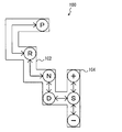
 図4を参照して、シフトレバー502の移動経路について説明する。運転者は、シフトレバー502をシフトゲート100に沿って移動することが可能である。シフトゲート100は、メインゲート102とサブゲート104とで構成される。 The movement path of the shift lever 502 will be described with reference to FIG. The driver can move the shift lever 502 along the shift gate 100. The shift gate 100 includes a main gate 102 and a sub gate 104.
 メインゲート102には、複数のシフトポジション、具体的には、前進ポジション(Dポジション)、ニュートラルポジション(Nポジション)、パーキングポジション(Pポジション)、リバースポジション(Rポジション)が設けられている。 The main gate 102 is provided with a plurality of shift positions, specifically, a forward position (D position), a neutral position (N position), a parking position (P position), and a reverse position (R position).
 サブゲート104は、メインゲート102におけるDポジションと接続される。サブゲート104の中央部には、Sポジションが設けられる。サブゲート104の上端部および下端部には、それぞれ、(+)ポジション、(-)ポジションが設けられている。 The sub gate 104 is connected to the D position in the main gate 102. An S position is provided at the center of the sub-gate 104. A (+) position and a (−) position are provided at the upper end and the lower end of the sub-gate 104, respectively.
 運転者がシフトレバー502をSポジションから(+)ポジションに移動させる操作(以下、「(+)操作」という)を行なうと、シフトポジションセンサ504は、(+)操作を示す信号を制御装置600に送信する。一方、運転者がシフトレバー502をSポジションから(-)ポジションに移動される操作(以下、「(-)操作」という)を行なうと、シフトポジションセンサ504は、(-)操作を示す信号を制御装置600に送信する。 When the driver performs an operation of moving the shift lever 502 from the S position to the (+) position (hereinafter referred to as “(+) operation”), the shift position sensor 504 sends a signal indicating the (+) operation to the control device 600. Send to. On the other hand, when the driver performs an operation of moving the shift lever 502 from the S position to the (−) position (hereinafter referred to as “(−) operation”), the shift position sensor 504 outputs a signal indicating the (−) operation. It transmits to the control apparatus 600.
 運転者はシフトレバー502の位置を変更することによって、動力分割機構200の動力伝達状態を変更することができる。 The driver can change the power transmission state of the power split mechanism 200 by changing the position of the shift lever 502.
 シフトレバー502の位置がDポジションであると、制御装置600は、自動変速モードでハイブリッド車両1を制御する。自動変速モードでは、制御装置600は、車速Vに対するエンジン回転速度NEの比が車両の状態に応じて連続的に変化するようにエンジン120およびMG140を制御する。 When the position of the shift lever 502 is the D position, the control device 600 controls the hybrid vehicle 1 in the automatic transmission mode. In the automatic transmission mode, control device 600 controls engine 120 and MG 140 such that the ratio of engine rotation speed NE to vehicle speed V changes continuously according to the state of the vehicle.
 一方、シフトレバー502の位置がSポジションであると、制御装置600は、手動変速モードでハイブリッド車両1を制御する。手動変速モードでは、制御装置600は、運転者によって選択されたシフト段(以下、「選択シフト段」という)に応じて車速Vに対するエンジン回転速度NEの比を限定する。具体的には、制御装置600は、車速Vおよび選択シフト段に基づいてエンジン回転速度NEの下限回転速度NEminを設定し、上述した図3に示す関係を利用して、エンジン回転速度NEを下限回転速度NEmin以上の値に制限する。これにより、有段式の自動変速機を搭載していないハイブリッド車両1においても、擬似的なシフト段を形成させることができる。 On the other hand, if the position of the shift lever 502 is the S position, the control device 600 controls the hybrid vehicle 1 in the manual shift mode. In the manual shift mode, control device 600 limits the ratio of engine speed NE to vehicle speed V according to the shift stage selected by the driver (hereinafter referred to as “selected shift stage”). Specifically, the control device 600 sets the lower limit rotational speed NEmin of the engine rotational speed NE based on the vehicle speed V and the selected shift stage, and uses the relationship shown in FIG. 3 described above to set the lower limit of the engine rotational speed NE. The value is limited to a value equal to or higher than the rotational speed NEmin. Thereby, a pseudo shift stage can be formed even in the hybrid vehicle 1 in which the stepped automatic transmission is not mounted.
 制御装置600は、(+)操作を示す信号を受信すると、選択シフト段を現在のシフト段よりも1段高速側のシフト段に変更する。一方、制御装置600は、(-)操作を示す信号を受信すると、選択シフト段を現在のシフト段よりも1段低速側のシフト段に変更する。 When the control device 600 receives the signal indicating the (+) operation, the control device 600 changes the selected shift stage to a shift stage that is one stage faster than the current shift stage. On the other hand, when receiving the signal indicating the (−) operation, control device 600 changes the selected shift stage to a shift stage that is one stage lower than the current shift stage.
 図5は、車速V、選択シフト段、下限回転速度NEminの関係を示す。なお、以下の説明では、運転者が選択可能なシフト段が、低速シフト段(Loギヤ)、中速シフト段(Midギヤ)、高速シフト段(Hiギヤ)の3つである場合を例示的に示すが、運転者が選択可能なシフト段の数は3つに限定されるものではない。 FIG. 5 shows the relationship between the vehicle speed V, the selected shift stage, and the lower limit rotational speed NEmin. In the following description, the case where the driver can select three shift stages, that is, a low speed shift stage (Lo gear), a medium speed shift stage (Mid gear), and a high speed shift stage (Hi gear) is exemplified. However, the number of shift stages that can be selected by the driver is not limited to three.
 下限回転速度NEminは、車速Vと選択シフト段とをパラメータとして設定される。低速側のシフト段であるほど、車速Vに対する下限回転速度NEminの比(=NEmin/V)は大きい値に設定される。たとえば、図5に示すように、車速V=V0の時におけるHiギヤ、Midギヤ、Loギヤでの下限回転速度NEminをそれぞれN1、N2、N3とすると、N1<N2<N3の関係が成立する。したがって、たとえば車速V=V0での走行中に選択シフト段がMidギヤからLoギヤに変更された場合、下限回転速度NEminはN2からN3に増加される。これに伴い、エンジン回転速度NEもN3以上の値に制限されて増加される。その結果、あたかも運転者のシフト操作に応じて自動変速機をダウンシフトさせたかのような感覚を運転者に擬似的に与えることができる。 The lower limit rotational speed NEmin is set with the vehicle speed V and the selected shift stage as parameters. The ratio of the lower limit rotational speed NEmin to the vehicle speed V (= NEmin / V) is set to a larger value as the shift stage is on the lower speed side. For example, as shown in FIG. 5, assuming that the lower limit rotational speeds NEmin at the Hi gear, Mid gear, and Lo gear at the vehicle speed V = V0 are N1, N2, and N3, the relationship of N1 <N2 <N3 is established. . Therefore, for example, when the selected shift stage is changed from the Mid gear to the Lo gear during traveling at the vehicle speed V = V0, the lower limit rotational speed NEmin is increased from N2 to N3. Along with this, the engine speed NE is also limited and increased to a value equal to or higher than N3. As a result, it is possible to give the driver a feeling as if the automatic transmission was downshifted according to the driver's shift operation.
 次に、本実施例におけるキックダウン制御について説明する。有段式の自動変速機を搭載した自動車であれば、キックダウンスイッチ508がオンされた場合、より大きな駆動力を発生させる(より強い加速力を得る)ために自動変速機をダウンシフトさせるのが一般的である。しかしながら、本実施例におけるハイブリッド車両1には、有段式の自動変速機は搭載されていない。 Next, kick down control in this embodiment will be described. If the vehicle is equipped with a stepped automatic transmission, when the kickdown switch 508 is turned on, the automatic transmission is downshifted to generate a larger driving force (to obtain a stronger acceleration force). Is common. However, the hybrid vehicle 1 in this embodiment is not equipped with a stepped automatic transmission.
 そこで、制御装置600は、KDオフ時の駆動力に予め制限をかけておき、KDオン時にその制限を解除して駆動力を増加させる。この一連の制御が本実施例におけるキックダウン制御である。このキックダウン制御によって、有段の自動変速機を搭載しないハイブリッド車両1において、KDオン時にあたかも自動変速機をダウンシフトさせたかのような感覚(いわゆるキックダウンフィーリング)を運転者に擬似的に与えることができる。 Therefore, the control device 600 limits the driving force when KD is turned off in advance, and releases the restriction when KD is turned on to increase the driving force. This series of controls is the kick down control in this embodiment. By this kick-down control, in the hybrid vehicle 1 that does not have a stepped automatic transmission, the driver feels as if the automatic transmission has been downshifted (so-called kick-down feeling) when KD is turned on. be able to.
 さらに、本実施例では、手動変速モードでのキックダウン制御において駆動力を制限する量を選択シフト段ごとに可変としている。具体的には、制御装置600は、選択シフト段が高速側のシフト段であるほど駆動力を制限する量を大きくする。これによって、選択シフト段が高速側のシフト段であるほどKDオフからKDオンに変化した時の駆動力の増加量を大きくし、選択シフト段に応じたより自然なキックダウンフィーリングを実現することが可能となる。このように、手動変速モードでのキックダウン制御においてKDオフ時に駆動力を制限する量を選択シフト段ごとに可変とする点が本実施例の最も特徴的な点である。 Furthermore, in this embodiment, the amount for limiting the driving force in the kick down control in the manual shift mode is variable for each selected shift stage. Specifically, the control device 600 increases the amount of limiting the driving force as the selected shift stage is the shift stage on the high speed side. As a result, the higher the shift stage of the selected shift stage, the larger the increase in driving force when changing from KD off to KD on, thereby realizing a more natural kick-down feeling according to the selected shift stage. Is possible. Thus, in the kickdown control in the manual shift mode, the most characteristic point of the present embodiment is that the amount for limiting the driving force when KD is off is variable for each selected shift stage.
 図6は、制御装置600の、手動変速モードでの駆動力制御に関する部分の機能ブロック図である。なお、図6に示した各機能ブロックについては、当該機能を有するハードウェア(電子回路等)を制御装置600に設けることによって実現してもよいし、当該機能に相当するソフトウェア処理(プログラムの実行等)を制御装置600に行なわせることよって実現してもよい。 FIG. 6 is a functional block diagram of a portion related to driving force control in the manual transmission mode of the control device 600. Note that each functional block shown in FIG. 6 may be realized by providing hardware (such as an electronic circuit) having the function in the control device 600, or software processing corresponding to the function (execution of a program) Etc.) may be realized by causing the control device 600 to perform the above.
 制御装置600は、基本駆動力算出部610、制限率算出部620、要求駆動力算出部630、要求パワー算出部640、下限回転速度算出部650、エンジン制御部660、MG制御部670を含む。 Control device 600 includes a basic driving force calculation unit 610, a limiting rate calculation unit 620, a required driving force calculation unit 630, a required power calculation unit 640, a lower limit rotation speed calculation unit 650, an engine control unit 660, and an MG control unit 670.
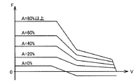
 基本駆動力算出部610は、車速V、アクセル操作量Aに基づいて、ハイブリッド車両1を駆動させるための基本駆動力Fを算出する。 The basic driving force calculation unit 610 calculates a basic driving force F for driving the hybrid vehicle 1 based on the vehicle speed V and the accelerator operation amount A.
 図7に、車速V、アクセル操作量A、基本駆動力Fの対応関係を示す。図7に示すように、アクセル操作量Aが大きいほど、基本駆動力Fは大きい値に設定される。また、車速Vが所定値を越える範囲では、車速Vが大きいほど基本駆動力Fは小さい値に設定される。たとえば、キックダウンスイッチ508にアクセルペダル507が当接した以降は、アクセル操作量Aが80パーセント以上となるため、図7において「A=80%以上」と記載されたラインを用いて、車速Vに対応する基本駆動力Fが算出さることになる。 FIG. 7 shows a correspondence relationship between the vehicle speed V, the accelerator operation amount A, and the basic driving force F. As shown in FIG. 7, the basic driving force F is set to a larger value as the accelerator operation amount A is larger. In the range where the vehicle speed V exceeds a predetermined value, the basic driving force F is set to a smaller value as the vehicle speed V increases. For example, after the accelerator pedal 507 comes into contact with the kick down switch 508, the accelerator operation amount A becomes 80% or more. Therefore, the vehicle speed V is expressed using the line “A = 80% or more” in FIG. The basic driving force F corresponding to is calculated.
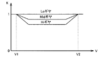
 図6に戻って、制限率算出部620は、車速V、選択シフト段に基づいて、KDオフ時の駆動力の制限率Kを算出する。なお、選択シフト段は、上述したように、運転者による(+)操作あるいは(-)操作によって判断される。 Returning to FIG. 6, the limiting rate calculation unit 620 calculates the limiting rate K of the driving force when KD is off based on the vehicle speed V and the selected shift stage. As described above, the selected shift stage is determined by a (+) operation or a (−) operation by the driver.
 図8に、車速V、選択シフト段、制限率Kの対応関係を示す。図8に示すように、車速Vが所定速度V1よりも低い範囲、あるいは、車速Vが所定速度V2(>V1)よりも高い範囲では、制限率Kは選択シフト段に関わらず「1」に設定される。一方、車速Vが所定速度V1から所定速度V2までの範囲では、選択シフト段が高速側のシフト段であるほど制限率Kは小さい値に設定される。なお、本実施例では、図8に示すように、選択シフト段がLoギヤである場合は車速Vが所定速度V1から所定速度V2までの範囲であっても制限率Kはそのまま「1」に設定される。 FIG. 8 shows the correspondence between the vehicle speed V, the selected shift stage, and the limit rate K. As shown in FIG. 8, in a range where the vehicle speed V is lower than the predetermined speed V1 or a range where the vehicle speed V is higher than the predetermined speed V2 (> V1), the limiting rate K is “1” regardless of the selected shift stage. Is set. On the other hand, when the vehicle speed V is in the range from the predetermined speed V1 to the predetermined speed V2, the limit rate K is set to a smaller value as the selected shift stage is the higher shift stage. In the present embodiment, as shown in FIG. 8, when the selected shift stage is the Lo gear, the limiting rate K remains “1” even if the vehicle speed V is in the range from the predetermined speed V1 to the predetermined speed V2. Is set.
 再び図6に戻って、要求駆動力算出部630は、基本駆動力算出部610からの基本駆動力F、制限率算出部620からの制限率K、キックダウンスイッチ508からのキックダウン信号KDに基づいて、要求駆動力Freqを算出する。要求駆動力算出部630は、KDオフ時には、基本駆動力Fと制限率Kとの積を算出し、その結果を要求駆動力Freqに設定する。一方、要求駆動力算出部630は、KDオン時には、基本駆動力Fをそのまま要求駆動力Freqに設定する。 Returning to FIG. 6 again, the required driving force calculation unit 630 receives the basic driving force F from the basic driving force calculation unit 610, the limiting rate K from the limiting rate calculation unit 620, and the kick down signal KD from the kick down switch 508. Based on this, the required driving force Freq is calculated. The required driving force calculation unit 630 calculates the product of the basic driving force F and the limiting rate K when KD is off, and sets the result as the required driving force Freq. On the other hand, the required driving force calculation unit 630 sets the basic driving force F to the required driving force Freq as it is when KD is on.
 図9に、車速V、選択シフト段、要求駆動力Freqの対応関係を、KDオフ時とKDオン時とに分けて示す。なお、図9においては、KDオン時の要求駆動力Freqを破線で示し、KDオフ時の要求駆動力Freqを実線で示す。したがって、図9に示す破線と実線との差がKDオフからKDオンに変化した時の駆動力の増加量に相当する。 FIG. 9 shows the correspondence relationship between the vehicle speed V, the selected shift stage, and the required driving force Freq separately for when KD is off and when KD is on. In FIG. 9, the required driving force Freq when KD is on is indicated by a broken line, and the required driving force Freq when KD is off is indicated by a solid line. Therefore, the difference between the broken line and the solid line shown in FIG. 9 corresponds to the amount of increase in driving force when the KD is turned off to KD on.
 KDオン時は、要求駆動力Freq=基本駆動力Fであり、制限率Kの影響を受けない。すなわち、KDオン時の要求駆動力Freqは、アクセル操作量Aが80パーセント以上の場合の基本駆動力F(図7において「A=80%以上」と記載されたライン)となる。 When KD is on, required drive force Freq = basic drive force F and is not affected by the limiting rate K. That is, the required driving force Freq when KD is on is the basic driving force F when the accelerator operation amount A is 80% or more (the line indicated as “A = 80% or more” in FIG. 7).
 一方、KDオフ時は、要求駆動力Freq=基本駆動力F×制限率Kであり、要求駆動力Freqが制限率Kによって制限される。そして、制限率Kが高速側のシフト段であるほど小さい値に設定される(上述の図8参照)。したがって、KDオフ時の要求駆動力Freqは、基本駆動力Fに対して、高速側のシフト段であるほどより大きく制限されることになる。 On the other hand, when KD is off, the required driving force Freq = the basic driving force F × the limiting rate K, and the required driving force Freq is limited by the limiting rate K. Then, the limiting rate K is set to a smaller value as the shift stage is on the higher speed side (see FIG. 8 described above). Therefore, the required driving force Freq when KD is off is more limited as the shift stage is higher than the basic driving force F.
 そのため、KDオフからKDオンに変化した時の駆動力の増加量(図9に示す破線と実線との差)は、選択シフト段が高速側のシフト段であるほど大きくなり、選択シフト段に応じたより自然な加速フィーリングを実現することが可能となる。 Therefore, the amount of increase in the driving force when changing from KD off to KD on (difference between the broken line and the solid line shown in FIG. 9) becomes larger as the selected shift stage is the higher-speed side shift stage. A more natural acceleration feeling can be realized.
 なお、有段式の自動変速機を搭載した車両では、最も低速側のシフト段での走行中はキックダウンスイッチがオンされても当然ながらダウンシフトは出来ない。この点を考慮し、本実施例では、選択シフト段がLoギヤ(最も低速側のシフト段)である場合、制限率Kを常に「1」に設定し(上述の図8参照)、KDオフ時であっても実質的には要求駆動力Freqを制限しないようにしている。言い換えれば、選択シフト段がLoギヤである場合は、KDオフからKDオンに変化しても駆動力を変化させないようにしている。そのため、有段式の自動変速機を搭載しないハイブリッド車両1においても、有段式の自動変速機を搭載した車両により近いフィーリングを運転者に与えることができる。 In vehicles equipped with a stepped automatic transmission, it is of course impossible to downshift even when the kickdown switch is turned on while traveling at the lowest speed shift stage. In consideration of this point, in this embodiment, when the selected shift stage is the Lo gear (the lowest speed shift stage), the limiting rate K is always set to “1” (see FIG. 8 described above), and the KD is off. Even if it is time, the required driving force Freq is not substantially limited. In other words, when the selected shift stage is the Lo gear, the driving force is not changed even if the KD is changed from KD off to KD on. Therefore, even in the hybrid vehicle 1 not equipped with a stepped automatic transmission, the driver can be given a feeling closer to that of the vehicle equipped with the stepped automatic transmission.
 図6に戻って、要求パワー算出部640は、要求駆動力算出部630からの要求駆動力Freqに基づいて、ハイブリッド車両1の全体に要求される車両要求パワーPreqを算出する。たとえば、要求パワー算出部640は、バッテリ150が要求する充放電要求パワーPbを算出し、要求駆動力Freqと充放電要求パワーPbとの和を、車両要求パワーPとして算出する。 Referring back to FIG. 6, the required power calculation unit 640 calculates the required vehicle power Preq required for the entire hybrid vehicle 1 based on the required driving force Freq from the required driving force calculation unit 630. For example, required power calculation unit 640 calculates charge / discharge required power Pb required by battery 150, and calculates the sum of required drive power Freq and charge / discharge required power Pb as vehicle required power P.
 下限回転速度算出部650は、上述したように、車速V、選択シフト段をパラメータとして、エンジン120の下限回転速度NEminを算出する(上述の図5参照)。 As described above, the lower limit rotational speed calculation unit 650 calculates the lower limit rotational speed NEmin of the engine 120 using the vehicle speed V and the selected shift stage as parameters (see FIG. 5 described above).
 エンジン制御部660は、車両要求パワーPreq、下限回転速度NEminなどに基づいて、要求エンジン回転速度NEreqおよび要求エンジントルクTEreqを算出する。たとえば、エンジン制御部660は、NEreq×TEreq=Preqの関係が成立するように、要求エンジン回転速度NEreqおよび要求エンジントルクTEreqを算出する。この際、エンジン制御部660は、要求エンジン回転速度NEreqを下限回転速度NEmin以上の値に制限する。そして、エンジン制御部660は、エンジン回転速度NEが要求エンジン回転速度NEreqとなるように、かつ、エンジントルクTEが要求エンジントルクTEreqとなるように、エンジン120を制御する。そのため、エンジン回転速度NEは、選択シフト段に応じて制限されることになる。 The engine control unit 660 calculates the required engine rotational speed NEreq and the required engine torque TEreq based on the vehicle required power Prereq, the lower limit rotational speed NEmin, and the like. For example, engine control unit 660 calculates required engine speed NEreq and required engine torque TEreq so that the relationship NEreq × TEreq = Preq is established. At this time, the engine control unit 660 limits the requested engine speed NEreq to a value equal to or higher than the lower limit speed NEmin. Then, the engine control unit 660 controls the engine 120 so that the engine rotational speed NE becomes the required engine rotational speed NEreq and the engine torque TE becomes the required engine torque TEreq. Therefore, the engine speed NE is limited according to the selected shift stage.
 MG制御部670は、実際の車両駆動力が車両要求パワーPreqとなるように、MG140を制御する。たとえば、MG制御部670は、図3に示した関係を考慮してエンジン回転速度NEが要求エンジン回転速度NEreqとなるように、第1MG141の要求トルクTm1を算出する。次に、MG制御部670は、要求エンジントルクTEreqおよび第1MG141の要求トルクTm1を車両駆動力に換算したトルクと車両要求パワーPreqとの差分を第2MG142の要求トルクTm2として算出する。そして、MG制御部670は、第1MG141の実トルクが要求トルクTm1となるように、かつ、第2MG142の実トルクが要求トルクTm2となるように、第1MG141および第2MGを制御する。 The MG control unit 670 controls the MG 140 so that the actual vehicle driving force becomes the vehicle required power Preq. For example, MG control unit 670 calculates required torque Tm1 of first MG 141 so that engine speed NE becomes required engine speed NEreq in consideration of the relationship shown in FIG. Next, MG control unit 670 calculates a difference between torque obtained by converting requested engine torque TEreq and requested torque Tm1 of first MG 141 into vehicle driving force and requested vehicle power Preq as requested torque Tm2 of second MG 142. Then, MG control unit 670 controls first MG 141 and second MG so that the actual torque of first MG 141 becomes required torque Tm1 and the actual torque of second MG 142 becomes required torque Tm2.
 エンジン制御部660およびMG制御部670の機能によって、実際の車両駆動力が車両要求パワーPreqに対応した値となる。 By the functions of the engine control unit 660 and the MG control unit 670, the actual vehicle driving force becomes a value corresponding to the vehicle required power Preq.
 図10は、上述の制御装置600の機能を実現するための処理手順を示すフローチャートである。このフローチャートに示す処理は、予め定められたサイクルタイムで繰り返し実行される。また、このフローチャートの各ステップ(以下、ステップを「S」と略す)は、基本的には制御装置600によるソフトウェア処理によって実現されるが、制御装置600に設けられた電子回路等によるハードウェア処理によって実現されてもよい。 FIG. 10 is a flowchart showing a processing procedure for realizing the function of the control device 600 described above. The process shown in this flowchart is repeatedly executed at a predetermined cycle time. Each step of the flowchart (hereinafter, “step” is abbreviated as “S”) is basically realized by software processing by the control device 600, but hardware processing by an electronic circuit or the like provided in the control device 600. It may be realized by.
 S1にて、制御装置600は、車速V、アクセル操作量Aに基づいて、基本駆動力Fを算出する(上述の図7参照)。 At S1, control device 600 calculates basic driving force F based on vehicle speed V and accelerator operation amount A (see FIG. 7 described above).
 S2にて、制御装置600は、運転者によるシフトレバー502の操作(上述した(+)操作あるいは(-)操作など)に基づいて、選択シフト段を判断する。 In S2, control device 600 determines the selected shift stage based on the operation of shift lever 502 by the driver (the above-described (+) operation or (-) operation, etc.).
 S3にて、制御装置600は、車速V、選択シフト段に基づいて、KDオフ時の駆動力の制限率Kを算出する。この際、制御装置600は、上述の図8に示したように、選択シフト段が高速側のシフト段であるほど制限率Kを小さい値にする。 In S3, control device 600 calculates drive force limiting rate K when KD is off based on vehicle speed V and the selected shift stage. At this time, as shown in FIG. 8 described above, the control device 600 sets the limiting rate K to a smaller value as the selected shift stage is the higher-speed shift stage.
 S4にて、制御装置600は、KDオフであるか否かを判断する。KDオフであると(S4にてYES)、処理はS5に移される。そうでないと(S4にてNO)、処理はS6に移される。 In S4, control device 600 determines whether or not KD is off. If KD is off (YES in S4), the process proceeds to S5. Otherwise (NO in S4), the process proceeds to S6.
 S5にて、制御装置600は、基本駆動力Fと制限率Kとの積を、要求駆動力Freqに設定する。すなわち、制限率Kを用いて基本駆動力Fを制限する。 In S5, control device 600 sets the product of basic driving force F and limiting rate K to required driving force Freq. That is, the basic driving force F is limited using the limiting rate K.
 S6にて、制御装置600は、基本駆動力Fをそのまま要求駆動力Freqに設定する。すなわち、制限率Kを用いた基本駆動力Fの制限を行なわない。本処理の直前まで基本駆動力Fを制限していた場合には、本処理で、基本駆動力Fの制限が解除されることになる。 In S6, control device 600 sets basic driving force F as requested driving force Freq as it is. That is, the basic driving force F is not limited using the limiting rate K. When the basic driving force F is limited until immediately before this processing, the limitation on the basic driving force F is released in this processing.
 S7にて、制御装置600は、上述したように、要求駆動力Freqに基づいて車両要求パワーPreqを算出し、実際の車両駆動力が車両要求パワーPreqとなるように、エンジン120およびMG140を制御する。 In S7, as described above, control device 600 calculates vehicle required power Preq based on required driving force Freq, and controls engine 120 and MG 140 so that the actual vehicle driving force becomes vehicle required power Preq. To do.
 図11に、本実施例におけるキックダウン制御を実行した場合の駆動力のタイミンングチャートを示す。なお、図11において、一点鎖線で示す駆動力は選択シフト段がLoギヤである場合の駆動力を示し、実線で示す駆動力は選択シフト段がMidギヤである場合の駆動力を示し、破線で示す駆動力は選択シフト段がHiギヤである場合の駆動力を示す。 FIG. 11 shows a driving force timing chart when the kick-down control in this embodiment is executed. In FIG. 11, the driving force indicated by the one-dot chain line indicates the driving force when the selected shift stage is the Lo gear, the driving force indicated by the solid line indicates the driving force when the selected shift stage is the Mid gear, The driving force indicated by indicates a driving force when the selected shift stage is a Hi gear.
 運転者がアクセルペダル507を踏み始め、時刻t1にてアクセル操作量Aが80パーセントに達すると、アクセルペダル507がキックダウンスイッチ508に当接する。そして、時刻t2にて運転者がさらに大きな踏力でアクセルペダル507を踏み込むと、アクセル操作量Aが80パーセントよりも増加し、キックダウンスイッチ508がオンされる。 When the driver starts stepping on the accelerator pedal 507 and the accelerator operation amount A reaches 80% at time t1, the accelerator pedal 507 contacts the kick-down switch 508. When the driver depresses the accelerator pedal 507 with a greater pedaling force at time t2, the accelerator operation amount A increases more than 80%, and the kick down switch 508 is turned on.
 キックダウンスイッチ508がオフである時刻t2以前では、選択シフト段が高速側であるほど制限率Kが小さい値に設定されるため、Midギヤでの駆動力はLoギヤでの駆動力よりも制限され、さらに、Hiギヤでの駆動力はMidギヤでの駆動力よりも制限される。なお、Loギヤでの制限率は「1」であり、実質的に駆動力を制限していない状態である。 Before time t2 when the kickdown switch 508 is off, the limit rate K is set to a smaller value as the selected shift stage is higher, so the driving force in the Mid gear is more limited than the driving force in the Lo gear. Furthermore, the driving force in the Hi gear is more limited than the driving force in the Mid gear. Note that the limiting rate at the Lo gear is “1”, and the driving force is not substantially limited.
 キックダウンスイッチ508がオフからオンに変化する時刻t2で、制限率Kを用いた駆動力の制限が解除され、HiギヤあるいはMidギヤでの走行中であれば、駆動力が増加することになる。この際、Hiギヤである場合の駆動力の増加量βは、KDオフ時の制限量が大きかった分、Midギヤである場合の駆動力の増加量αよりも大きくなる。そのため、選択シフト段に応じた自然なキックダウンフィーリングを実現される。 At time t2 when the kick-down switch 508 changes from off to on, the restriction on the driving force using the restriction rate K is released, and the driving force increases if the vehicle is traveling in the Hi gear or the Mid gear. . At this time, the increase amount β of the driving force in the case of the Hi gear is larger than the increase amount α of the driving force in the case of the Mid gear because the limit amount when the KD is off is large. Therefore, a natural kick down feeling corresponding to the selected shift stage is realized.
 以上のように、本実施例では、KDオフ時に基本駆動力Fに予め制限率Kを用いて制限をかけておきKDオン時にその制限を解除することでキックダウンフィーリングを実現するのであるが、KDオフ時に駆動力を制限する量を高速側のシフト段であるほど大きくすることによって、高速側のシフト段であるほどKDオフからKDオンに変化した時の駆動力の増加量を大きくする。これにより、KDオフからKDオンに変化した時の駆動力の増加量を選択シフト段とは無関係に同じ量とする場合に比べて、選択シフト段に応じたより自然な加速フィーリングを実現することが可能となる。 As described above, in this embodiment, when the KD is off, the basic driving force F is limited in advance using the limiting rate K, and when the KD is on, the restriction is released and the kick-down feeling is realized. By increasing the amount of limiting the driving force when KD is off, the higher the shift stage on the high speed side, the larger the amount of increase in driving force when the shift stage is from KD off to KD on. . As a result, a more natural acceleration feeling corresponding to the selected shift stage can be realized as compared with the case where the amount of increase in driving force when changing from KD off to KD on is the same regardless of the selected shift stage. Is possible.
 なお、本実施例では、基本駆動力Fを選択シフト段に応じた制限率Kで制限したが、制限の対象は基本駆動力Fであることに限定されない。たとえば、車速V、アクセル操作量Aに基づいて基本駆動トルクを算出し、その基本駆動トルクを選択シフト段に応じた制限率Kで制限するようにしてもよい。 In this embodiment, the basic driving force F is limited by the limiting rate K corresponding to the selected shift stage. However, the limitation target is not limited to the basic driving force F. For example, the basic driving torque may be calculated based on the vehicle speed V and the accelerator operation amount A, and the basic driving torque may be limited by the limiting rate K corresponding to the selected shift stage.
 また、本実施例では、動力分割機構200を用いて車速Vに対するエンジン回転速度NEの比を選択シフト段に応じて変化させた(図5参照)が、選択シフト段に応じて変化させる対象はこれに限定されない。たとえば、選択シフト段に応じて変化させる対象を、駆動力の変化率、アクセル操作量Aに対する駆動力の大きさ、回生ブレーキ量などにしてもよい。この場合には、動力分割機構200を有さない車両にも容易に適用できる。 In the present embodiment, the ratio of the engine speed NE to the vehicle speed V is changed according to the selected shift stage using the power split mechanism 200 (see FIG. 5), but the object to be changed according to the selected shift stage is It is not limited to this. For example, the target to be changed according to the selected shift stage may be the driving force change rate, the magnitude of the driving force with respect to the accelerator operation amount A, the regenerative braking amount, or the like. In this case, the present invention can be easily applied to a vehicle that does not have the power split mechanism 200.
 今回開示された実施例はすべての点で例示であって制限的なものではないと考えられるべきである。本発明の範囲は上記した説明ではなくて請求の範囲によって示され、請求の範囲と均等の意味および範囲内でのすべての変更が含まれることが意図される。 The embodiment disclosed this time should be considered as illustrative in all points and not restrictive. The scope of the present invention is defined by the terms of the claims, rather than the description above, and is intended to include any modifications within the scope and meaning equivalent to the terms of the claims.
 1 ハイブリッド車両、141 第1MG、142 第2MG、100 シフトゲート、102 メインゲート、104 サブゲート、120 エンジン、143,144 レゾルバ回路、150 バッテリ、152 コンバータ、154 インバータ、160 減速機、170 ドライブシャフト、180 駆動輪、200 動力分割機構、202 サンギヤ、204 ピニオンギヤ、206 キャリア、208 リングギヤ、210 入力軸、220 出力軸、502 シフトレバー、504 シフトポジションセンサ、506 アクセルペダルポジションセンサ、507 アクセルペダル、508 キックダウンスイッチ、510 エンジン回転速度センサ、512 車速センサ、600 制御装置、610 基本駆動力算出部、620 制限率算出部、630 要求駆動力算出部、640 要求パワー算出部、650 下限回転速度算出部、660 エンジン制御部、670 MG制御部。 1 hybrid vehicle, 141 1st MG, 142 2nd MG, 100 shift gate, 102 main gate, 104 sub gate, 120 engine, 143, 144 resolver circuit, 150 battery, 152 converter, 154 inverter, 160 reducer, 170 drive shaft, 180 Drive wheel, 200 power split mechanism, 202 sun gear, 204 pinion gear, 206 carrier, 208 ring gear, 210 input shaft, 220 output shaft, 502 shift lever, 504 shift position sensor, 506 accelerator pedal position sensor, 507 accelerator pedal, 508 kick down Switch 510 engine speed sensor 512 vehicle speed sensor 600 control device 610 basic driving force calculation unit 6 0 limiting rate calculation unit, 630 required driving force calculation unit, 640 request power calculation section, 650 lower limit revolution speed calculating unit, 660 the engine control unit, 670 MG control unit.

Claims (7)

  1.  運転者が複数のシフト段のうちから選択した選択シフト段に応じた走行が可能な車両であって、
     前記車両を走行させるための駆動力を発生する駆動装置(120、140)と、
     運転者によるアクセル操作量が予め定められた量よりも小さい場合にオフされ、前記アクセル操作量が前記予め定められた量よりも大きい場合にオンされるスイッチ(508)と、
     前記スイッチのオフ時に前記駆動力を制限し前記スイッチのオン時に前記駆動力の制限を解除することによって前記スイッチがオフからオンに変化した時に前記駆動力を増加させるように、前記駆動装置を制御する制御装置(600)とを含み、
     前記制御装置は、前記選択シフト段に応じて、前記スイッチがオフからオンに変化した時の前記駆動力の増加量を変化させる、車両。
    A vehicle capable of traveling according to a selected shift stage selected from a plurality of shift stages by a driver,
    A driving device (120, 140) for generating a driving force for running the vehicle;
    A switch (508) which is turned off when the accelerator operation amount by the driver is smaller than a predetermined amount, and which is turned on when the accelerator operation amount is larger than the predetermined amount;
    The driving device is controlled to increase the driving force when the switch changes from off to on by limiting the driving force when the switch is off and releasing the restriction of the driving force when the switch is on. A control device (600) for
    The control device changes the amount of increase in the driving force when the switch changes from off to on in accordance with the selected shift stage.
  2.  前記制御装置は、前記選択シフト段が高速側のシフト段であるほど前記スイッチがオフからオンに変化した時の前記駆動力の増加量を大きい値にする、請求の範囲第1項に記載の車両。 2. The control device according to claim 1, wherein the control device increases the amount of increase in the driving force when the switch changes from off to on as the selected shift stage is a shift stage on a higher speed side. vehicle.
  3.  前記制御装置は、前記選択シフト段が高速側のシフト段であるほど前記スイッチがオフからオンに変化した時の前記駆動力の増加量を大きい値にするために、前記選択シフト段が高速側のシフト段であるほど前記スイッチのオフ時に前記駆動力を制限する量を大きい値にする、請求の範囲第2項に記載の車両。 In order to increase the amount of increase in the driving force when the switch is changed from OFF to ON as the selected shift stage is a higher-speed shift stage, the control device sets the selected shift stage to a higher-speed side. The vehicle according to claim 2, wherein an amount of limiting the driving force when the switch is turned off is set to a larger value as the shift stage becomes smaller.
  4.  前記制御装置は、前記選択シフト段が最も低速側のシフト段である場合は、前記スイッチのオフ時であっても前記駆動力を制限しない、請求の範囲第1項に記載の車両。 The vehicle according to claim 1, wherein the control device does not limit the driving force even when the switch is turned off when the selected shift stage is the lowest speed shift stage.
  5.  前記駆動装置は、電力を用いて前記駆動力を発生する回転電機(140)を少なくとも含み、
     前記車両は、少なくとも前記回転電機が発生する前記駆動力によって走行することが可能な電気車両あるいはハイブリッド車両である、請求の範囲第1項に記載の車両。
    The driving device includes at least a rotating electrical machine (140) that generates the driving force using electric power,
    The vehicle according to claim 1, wherein the vehicle is an electric vehicle or a hybrid vehicle that can travel at least by the driving force generated by the rotating electrical machine.
  6.  運転者が複数のシフト段のうちから選択した選択シフト段に応じた走行が可能な車両であって、
     前記車両を走行させるための駆動力を発生する駆動装置(120、140)と、
     運転者によるアクセル操作量が予め定められた量よりも小さい場合にオフされ、前記アクセル操作量が前記予め定められた量よりも大きい場合にオンされるスイッチ(508)と、
     前記スイッチのオフ時に前記選択シフト段に応じて前記駆動力を制限し前記スイッチのオン時に前記駆動力の制限を解除することによって前記スイッチがオフからオンに変化した時に前記駆動力を増加させるように、前記駆動装置を制御する制御装置(600)とを含み、
     前記制御装置は、
     前記アクセル操作量に応じた基本駆動力を制限するために用いられる制限率を前記選択シフト段に応じて算出する算出部(620)と、
     前記スイッチのオフ時に前記制限率を用いて前記基本駆動力を制限し、前記スイッチのオン時に前記制限率を用いた前記基本駆動力の制限を解除することによって前記スイッチがオフからオンに変化した時に前記駆動力を増加させるように、前記駆動装置を制御する制御部(630、640、650、660、670)とを含み、
     前記算出部は、前記選択シフト段が最も低速側のシフト段である場合、前記基本駆動力を実質的に制限しないように前記制限率を算出し、前記選択シフト段が最も低速側のシフト段でない場合、前記選択シフト段が高速側のシフト段であるほど前記基本駆動力を制限する量がより大きくなるように前記制限率を算出する、車両。
    A vehicle capable of traveling according to a selected shift stage selected from a plurality of shift stages by a driver,
    A driving device (120, 140) for generating a driving force for running the vehicle;
    A switch (508) which is turned off when the accelerator operation amount by the driver is smaller than a predetermined amount, and which is turned on when the accelerator operation amount is larger than the predetermined amount;
    The driving force is limited according to the selected shift stage when the switch is turned off, and the driving force is increased when the switch changes from off to on by releasing the restriction of the driving force when the switch is turned on. And a control device (600) for controlling the drive device,
    The control device includes:
    A calculation unit (620) that calculates a limiting rate used to limit the basic driving force according to the accelerator operation amount according to the selected shift stage;
    When the switch is turned off, the basic driving force is limited using the limiting rate, and when the switch is turned on, the basic driving force is released using the limiting rate, so that the switch is changed from OFF to ON. A control unit (630, 640, 650, 660, 670) for controlling the driving device to increase the driving force sometimes.
    When the selected shift stage is the slowest shift stage, the calculation unit calculates the limiting rate so as not to substantially limit the basic driving force, and the selected shift stage is the slowest shift stage. Otherwise, the vehicle is configured to calculate the limiting rate so that the amount of limiting the basic driving force becomes larger as the selected shift stage is a higher speed stage.
  7.  運転者が複数のシフト段のうちから選択した選択シフト段に応じた走行が可能な車両の制御装置(600)が行なう制御方法であって、前記車両は、前記車両を走行させるための駆動力を発生する駆動装置(120、140)と、運転者によるアクセル操作量が予め定められた量よりも小さい場合にオフされ、前記アクセル操作量が前記予め定められた量よりも大きい場合にオンされるスイッチ(508)とを備え、
     前記制御方法は、
     前記選択シフト段を判断するステップと、
     前記スイッチのオフ時に前記駆動力を制限し前記スイッチのオン時に前記駆動力の制限を解除することによって前記スイッチがオフからオンに変化した時に前記駆動力を増加させるように、前記駆動装置を制御するステップとを含み、
     前記駆動装置を制御するステップは、前記選択シフト段に応じて、前記スイッチがオフからオンに変化した時の前記駆動力の増加量を変化させるステップを含む、車両の制御方法。
    A control method (600) for a vehicle capable of traveling according to a selected shift stage selected from a plurality of shift stages by a driver, wherein the vehicle is a driving force for causing the vehicle to travel. Is turned off when the accelerator operation amount by the driver is smaller than a predetermined amount, and turned on when the accelerator operation amount is larger than the predetermined amount. Switch (508),
    The control method is:
    Determining the selected shift stage;
    The driving device is controlled to increase the driving force when the switch changes from off to on by limiting the driving force when the switch is off and releasing the restriction of the driving force when the switch is on. Including the steps of:
    The step of controlling the driving device includes a step of changing an increase amount of the driving force when the switch is changed from OFF to ON according to the selected shift stage.
PCT/JP2010/051011 2010-01-27 2010-01-27 Vehicle and control method thereof WO2011092806A1 (en)

Priority Applications (5)

Application Number Priority Date Filing Date Title
PCT/JP2010/051011 WO2011092806A1 (en) 2010-01-27 2010-01-27 Vehicle and control method thereof
US13/575,438 US8768848B2 (en) 2010-01-27 2010-01-27 Vehicle and method of controlling the same
EP10844572.7A EP2529989B1 (en) 2010-01-27 2010-01-27 Vehicle and control method thereof
JP2011551614A JP5338923B2 (en) 2010-01-27 2010-01-27 Vehicle and control method thereof
CN201080056320.9A CN102656073B (en) 2010-01-27 2010-01-27 Vehicle and control method thereof

Applications Claiming Priority (1)

Application Number Priority Date Filing Date Title
PCT/JP2010/051011 WO2011092806A1 (en) 2010-01-27 2010-01-27 Vehicle and control method thereof

Publications (1)

Publication Number Publication Date
WO2011092806A1 true WO2011092806A1 (en) 2011-08-04

Family

ID=44318819

Family Applications (1)

Application Number Title Priority Date Filing Date
PCT/JP2010/051011 WO2011092806A1 (en) 2010-01-27 2010-01-27 Vehicle and control method thereof

Country Status (5)

Country Link
US (1) US8768848B2 (en)
EP (1) EP2529989B1 (en)
JP (1) JP5338923B2 (en)
CN (1) CN102656073B (en)
WO (1) WO2011092806A1 (en)

Cited By (3)

* Cited by examiner, † Cited by third party
Publication number Priority date Publication date Assignee Title
JP2013130225A (en) * 2011-12-21 2013-07-04 Toyota Motor Corp Gear shift instruction device of hybrid vehicle
CN111556834A (en) * 2017-11-14 2020-08-18 卡明斯公司 User selected control features for powertrain management
JP2022030834A (en) * 2020-08-07 2022-02-18 トヨタ自動車株式会社 Electric automobile

Families Citing this family (2)

* Cited by examiner, † Cited by third party
Publication number Priority date Publication date Assignee Title
KR101428250B1 (en) * 2012-12-06 2014-08-07 현대자동차주식회사 Apparatus and method for controlling kick down of accelerator pedal
US10699268B2 (en) * 2015-12-30 2020-06-30 Thales Dis France Sa Method, server and system for authorizing a transaction

Citations (2)

* Cited by examiner, † Cited by third party
Publication number Priority date Publication date Assignee Title
JP2007055535A (en) * 2005-08-26 2007-03-08 Toyota Motor Corp Automobile and control therefor
JP2007239504A (en) 2006-03-06 2007-09-20 Toyota Motor Corp Automobile and its control method

Family Cites Families (14)

* Cited by examiner, † Cited by third party
Publication number Priority date Publication date Assignee Title
JP2000175305A (en) * 1998-12-03 2000-06-23 Toyota Motor Corp Hybrid car
US6503170B1 (en) * 1999-08-20 2003-01-07 Toyota Jidosha Kabushiki Kaisha Control device for an automatic transmission
JP3600518B2 (en) * 2000-10-11 2004-12-15 トヨタ自動車株式会社 Vehicle speed change control device
JP2004090886A (en) * 2002-09-04 2004-03-25 Advics:Kk Traction control device of vehicle
DE10351656A1 (en) * 2003-11-05 2005-06-02 Daimlerchrysler Ag Motor vehicle, has accelerator pedal whose restoring force is based on torque levels corresponding to driving states such as deceleration, constant speed or acceleration
JP4857518B2 (en) * 2003-12-24 2012-01-18 トヨタ自動車株式会社 Vehicle control device
JP4055781B2 (en) * 2004-05-06 2008-03-05 トヨタ自動車株式会社 Hybrid vehicle and control method thereof
JP4584856B2 (en) * 2006-03-29 2010-11-24 ジヤトコ株式会社 Shift control device for automatic transmission
JP4165596B2 (en) * 2006-10-18 2008-10-15 トヨタ自動車株式会社 Braking / driving force control device
JP5018356B2 (en) * 2006-11-22 2012-09-05 日産自動車株式会社 Shift control device for automatic transmission
US7757800B2 (en) * 2006-12-12 2010-07-20 Grigoriy Epshteyn Monocylindrical hybrid powertrain and method of operation
JP4293249B2 (en) * 2007-03-06 2009-07-08 トヨタ自動車株式会社 Vehicle and control method thereof
CN101349345A (en) * 2007-07-20 2009-01-21 奇瑞汽车股份有限公司 Shift control method and apparatus of stepless speed variator
JP4960799B2 (en) * 2007-08-06 2012-06-27 本田技研工業株式会社 Control device for hybrid vehicle

Patent Citations (2)

* Cited by examiner, † Cited by third party
Publication number Priority date Publication date Assignee Title
JP2007055535A (en) * 2005-08-26 2007-03-08 Toyota Motor Corp Automobile and control therefor
JP2007239504A (en) 2006-03-06 2007-09-20 Toyota Motor Corp Automobile and its control method

Non-Patent Citations (1)

* Cited by examiner, † Cited by third party
Title
See also references of EP2529989A4

Cited By (5)

* Cited by examiner, † Cited by third party
Publication number Priority date Publication date Assignee Title
JP2013130225A (en) * 2011-12-21 2013-07-04 Toyota Motor Corp Gear shift instruction device of hybrid vehicle
CN111556834A (en) * 2017-11-14 2020-08-18 卡明斯公司 User selected control features for powertrain management
CN111556834B (en) * 2017-11-14 2024-01-30 卡明斯公司 User-selected control features for powertrain management
JP2022030834A (en) * 2020-08-07 2022-02-18 トヨタ自動車株式会社 Electric automobile
JP7298565B2 (en) 2020-08-07 2023-06-27 トヨタ自動車株式会社 Electric car

Also Published As

Publication number Publication date
JPWO2011092806A1 (en) 2013-05-30
CN102656073B (en) 2014-08-06
US20120303228A1 (en) 2012-11-29
EP2529989A1 (en) 2012-12-05
EP2529989A4 (en) 2014-12-24
EP2529989B1 (en) 2016-09-21
US8768848B2 (en) 2014-07-01
JP5338923B2 (en) 2013-11-13
CN102656073A (en) 2012-09-05

Similar Documents

Publication Publication Date Title
US10464440B2 (en) Vehicle
JP6627788B2 (en) Hybrid vehicle
US7957856B2 (en) Control device and control method of hybrid vehicle
JP7040363B2 (en) Vehicle control device
JP6149772B2 (en) Hybrid vehicle
JP5338923B2 (en) Vehicle and control method thereof
JP2013018375A (en) Control device of hybrid vehicle
JP2018191366A (en) vehicle
JP4114643B2 (en) Control device for vehicle drive device
JP2000115912A (en) Control equipment of hybrid vehicle
WO2013084292A1 (en) Gear shift instruction device
JP2021031023A (en) Hybrid vehicle
JP5724854B2 (en) Vehicle control device
JP5917866B2 (en) Vehicle control device
JP5359937B2 (en) Hybrid vehicle
JP2016124523A (en) Hybrid automobile
JP2011255700A (en) Hybrid drive apparatus for vehicle
JP2006275175A (en) Control device of hybrid car
KR20130055082A (en) Control method for preventing backward slipping of hybrid electric vehicles on slope road
JP2010241307A (en) Hybrid car and control method in shifting in-vehicle transmission
JP5786749B2 (en) Speed change instruction device
JP5987323B2 (en) Vehicle control device
JP7180968B2 (en) vehicle controller
JP2000278816A (en) Shift controller of electric vehicle
JP2021031038A (en) Hybrid vehicle

Legal Events

Date Code Title Description
WWE Wipo information: entry into national phase

Ref document number: 201080056320.9

Country of ref document: CN

121 Ep: the epo has been informed by wipo that ep was designated in this application

Ref document number: 10844572

Country of ref document: EP

Kind code of ref document: A1

WWE Wipo information: entry into national phase

Ref document number: 2011551614

Country of ref document: JP

REEP Request for entry into the european phase

Ref document number: 2010844572

Country of ref document: EP

WWE Wipo information: entry into national phase

Ref document number: 2010844572

Country of ref document: EP

WWE Wipo information: entry into national phase

Ref document number: 13575438

Country of ref document: US

NENP Non-entry into the national phase

Ref country code: DE