JP6149772B2 - Hybrid vehicle - Google Patents
Hybrid vehicle Download PDFInfo
- Publication number
- JP6149772B2 JP6149772B2 JP2014059960A JP2014059960A JP6149772B2 JP 6149772 B2 JP6149772 B2 JP 6149772B2 JP 2014059960 A JP2014059960 A JP 2014059960A JP 2014059960 A JP2014059960 A JP 2014059960A JP 6149772 B2 JP6149772 B2 JP 6149772B2
- Authority
- JP
- Japan
- Prior art keywords
- target value
- amount
- value
- region
- gear
- Prior art date
- Legal status (The legal status is an assumption and is not a legal conclusion. Google has not performed a legal analysis and makes no representation as to the accuracy of the status listed.)
- Expired - Fee Related
Links
- 230000005540 biological transmission Effects 0.000 claims description 49
- 230000008859 change Effects 0.000 claims description 36
- 238000001514 detection method Methods 0.000 claims description 4
- 238000004364 calculation method Methods 0.000 description 28
- 230000035939 shock Effects 0.000 description 20
- 238000010586 diagram Methods 0.000 description 10
- 239000000446 fuel Substances 0.000 description 8
- 230000006870 function Effects 0.000 description 5
- 230000007423 decrease Effects 0.000 description 3
- 230000004048 modification Effects 0.000 description 3
- 238000012986 modification Methods 0.000 description 3
- 238000002485 combustion reaction Methods 0.000 description 2
- 230000005611 electricity Effects 0.000 description 2
- 238000000034 method Methods 0.000 description 2
- HBBGRARXTFLTSG-UHFFFAOYSA-N Lithium ion Chemical compound [Li+] HBBGRARXTFLTSG-UHFFFAOYSA-N 0.000 description 1
- 239000003990 capacitor Substances 0.000 description 1
- 238000012937 correction Methods 0.000 description 1
- 238000007599 discharging Methods 0.000 description 1
- 230000001771 impaired effect Effects 0.000 description 1
- 238000002347 injection Methods 0.000 description 1
- 239000007924 injection Substances 0.000 description 1
- 229910001416 lithium ion Inorganic materials 0.000 description 1
- 230000007246 mechanism Effects 0.000 description 1
- 229910052987 metal hydride Inorganic materials 0.000 description 1
- 239000000203 mixture Substances 0.000 description 1
- 229910052759 nickel Inorganic materials 0.000 description 1
- PXHVJJICTQNCMI-UHFFFAOYSA-N nickel Substances [Ni] PXHVJJICTQNCMI-UHFFFAOYSA-N 0.000 description 1
- -1 nickel metal hydride Chemical class 0.000 description 1
- 238000010248 power generation Methods 0.000 description 1
- 230000008569 process Effects 0.000 description 1
- 238000012545 processing Methods 0.000 description 1
- 230000001172 regenerating effect Effects 0.000 description 1
- 230000008929 regeneration Effects 0.000 description 1
- 238000011069 regeneration method Methods 0.000 description 1
- 239000007858 starting material Substances 0.000 description 1
Images


Classifications
-
- B—PERFORMING OPERATIONS; TRANSPORTING
- B60—VEHICLES IN GENERAL
- B60W—CONJOINT CONTROL OF VEHICLE SUB-UNITS OF DIFFERENT TYPE OR DIFFERENT FUNCTION; CONTROL SYSTEMS SPECIALLY ADAPTED FOR HYBRID VEHICLES; ROAD VEHICLE DRIVE CONTROL SYSTEMS FOR PURPOSES NOT RELATED TO THE CONTROL OF A PARTICULAR SUB-UNIT
- B60W10/00—Conjoint control of vehicle sub-units of different type or different function
- B60W10/24—Conjoint control of vehicle sub-units of different type or different function including control of energy storage means
- B60W10/26—Conjoint control of vehicle sub-units of different type or different function including control of energy storage means for electrical energy, e.g. batteries or capacitors
-
- B—PERFORMING OPERATIONS; TRANSPORTING
- B60—VEHICLES IN GENERAL
- B60K—ARRANGEMENT OR MOUNTING OF PROPULSION UNITS OR OF TRANSMISSIONS IN VEHICLES; ARRANGEMENT OR MOUNTING OF PLURAL DIVERSE PRIME-MOVERS IN VEHICLES; AUXILIARY DRIVES FOR VEHICLES; INSTRUMENTATION OR DASHBOARDS FOR VEHICLES; ARRANGEMENTS IN CONNECTION WITH COOLING, AIR INTAKE, GAS EXHAUST OR FUEL SUPPLY OF PROPULSION UNITS IN VEHICLES
- B60K6/00—Arrangement or mounting of plural diverse prime-movers for mutual or common propulsion, e.g. hybrid propulsion systems comprising electric motors and internal combustion engines ; Control systems therefor, i.e. systems controlling two or more prime movers, or controlling one of these prime movers and any of the transmission, drive or drive units Informative references: mechanical gearings with secondary electric drive F16H3/72; arrangements for handling mechanical energy structurally associated with the dynamo-electric machine H02K7/00; machines comprising structurally interrelated motor and generator parts H02K51/00; dynamo-electric machines not otherwise provided for in H02K see H02K99/00
- B60K6/20—Arrangement or mounting of plural diverse prime-movers for mutual or common propulsion, e.g. hybrid propulsion systems comprising electric motors and internal combustion engines ; Control systems therefor, i.e. systems controlling two or more prime movers, or controlling one of these prime movers and any of the transmission, drive or drive units Informative references: mechanical gearings with secondary electric drive F16H3/72; arrangements for handling mechanical energy structurally associated with the dynamo-electric machine H02K7/00; machines comprising structurally interrelated motor and generator parts H02K51/00; dynamo-electric machines not otherwise provided for in H02K see H02K99/00 the prime-movers consisting of electric motors and internal combustion engines, e.g. HEVs
- B60K6/42—Arrangement or mounting of plural diverse prime-movers for mutual or common propulsion, e.g. hybrid propulsion systems comprising electric motors and internal combustion engines ; Control systems therefor, i.e. systems controlling two or more prime movers, or controlling one of these prime movers and any of the transmission, drive or drive units Informative references: mechanical gearings with secondary electric drive F16H3/72; arrangements for handling mechanical energy structurally associated with the dynamo-electric machine H02K7/00; machines comprising structurally interrelated motor and generator parts H02K51/00; dynamo-electric machines not otherwise provided for in H02K see H02K99/00 the prime-movers consisting of electric motors and internal combustion engines, e.g. HEVs characterised by the architecture of the hybrid electric vehicle
- B60K6/44—Series-parallel type
- B60K6/445—Differential gearing distribution type
-
- B—PERFORMING OPERATIONS; TRANSPORTING
- B60—VEHICLES IN GENERAL
- B60K—ARRANGEMENT OR MOUNTING OF PROPULSION UNITS OR OF TRANSMISSIONS IN VEHICLES; ARRANGEMENT OR MOUNTING OF PLURAL DIVERSE PRIME-MOVERS IN VEHICLES; AUXILIARY DRIVES FOR VEHICLES; INSTRUMENTATION OR DASHBOARDS FOR VEHICLES; ARRANGEMENTS IN CONNECTION WITH COOLING, AIR INTAKE, GAS EXHAUST OR FUEL SUPPLY OF PROPULSION UNITS IN VEHICLES
- B60K6/00—Arrangement or mounting of plural diverse prime-movers for mutual or common propulsion, e.g. hybrid propulsion systems comprising electric motors and internal combustion engines ; Control systems therefor, i.e. systems controlling two or more prime movers, or controlling one of these prime movers and any of the transmission, drive or drive units Informative references: mechanical gearings with secondary electric drive F16H3/72; arrangements for handling mechanical energy structurally associated with the dynamo-electric machine H02K7/00; machines comprising structurally interrelated motor and generator parts H02K51/00; dynamo-electric machines not otherwise provided for in H02K see H02K99/00
- B60K6/20—Arrangement or mounting of plural diverse prime-movers for mutual or common propulsion, e.g. hybrid propulsion systems comprising electric motors and internal combustion engines ; Control systems therefor, i.e. systems controlling two or more prime movers, or controlling one of these prime movers and any of the transmission, drive or drive units Informative references: mechanical gearings with secondary electric drive F16H3/72; arrangements for handling mechanical energy structurally associated with the dynamo-electric machine H02K7/00; machines comprising structurally interrelated motor and generator parts H02K51/00; dynamo-electric machines not otherwise provided for in H02K see H02K99/00 the prime-movers consisting of electric motors and internal combustion engines, e.g. HEVs
- B60K6/50—Architecture of the driveline characterised by arrangement or kind of transmission units
- B60K6/54—Transmission for changing ratio
- B60K6/547—Transmission for changing ratio the transmission being a stepped gearing
-
- B—PERFORMING OPERATIONS; TRANSPORTING
- B60—VEHICLES IN GENERAL
- B60L—PROPULSION OF ELECTRICALLY-PROPELLED VEHICLES; SUPPLYING ELECTRIC POWER FOR AUXILIARY EQUIPMENT OF ELECTRICALLY-PROPELLED VEHICLES; ELECTRODYNAMIC BRAKE SYSTEMS FOR VEHICLES IN GENERAL; MAGNETIC SUSPENSION OR LEVITATION FOR VEHICLES; MONITORING OPERATING VARIABLES OF ELECTRICALLY-PROPELLED VEHICLES; ELECTRIC SAFETY DEVICES FOR ELECTRICALLY-PROPELLED VEHICLES
- B60L53/00—Methods of charging batteries, specially adapted for electric vehicles; Charging stations or on-board charging equipment therefor; Exchange of energy storage elements in electric vehicles
-
- B—PERFORMING OPERATIONS; TRANSPORTING
- B60—VEHICLES IN GENERAL
- B60L—PROPULSION OF ELECTRICALLY-PROPELLED VEHICLES; SUPPLYING ELECTRIC POWER FOR AUXILIARY EQUIPMENT OF ELECTRICALLY-PROPELLED VEHICLES; ELECTRODYNAMIC BRAKE SYSTEMS FOR VEHICLES IN GENERAL; MAGNETIC SUSPENSION OR LEVITATION FOR VEHICLES; MONITORING OPERATING VARIABLES OF ELECTRICALLY-PROPELLED VEHICLES; ELECTRIC SAFETY DEVICES FOR ELECTRICALLY-PROPELLED VEHICLES
- B60L58/00—Methods or circuit arrangements for monitoring or controlling batteries or fuel cells, specially adapted for electric vehicles
- B60L58/10—Methods or circuit arrangements for monitoring or controlling batteries or fuel cells, specially adapted for electric vehicles for monitoring or controlling batteries
-
- B—PERFORMING OPERATIONS; TRANSPORTING
- B60—VEHICLES IN GENERAL
- B60W—CONJOINT CONTROL OF VEHICLE SUB-UNITS OF DIFFERENT TYPE OR DIFFERENT FUNCTION; CONTROL SYSTEMS SPECIALLY ADAPTED FOR HYBRID VEHICLES; ROAD VEHICLE DRIVE CONTROL SYSTEMS FOR PURPOSES NOT RELATED TO THE CONTROL OF A PARTICULAR SUB-UNIT
- B60W10/00—Conjoint control of vehicle sub-units of different type or different function
- B60W10/04—Conjoint control of vehicle sub-units of different type or different function including control of propulsion units
- B60W10/06—Conjoint control of vehicle sub-units of different type or different function including control of propulsion units including control of combustion engines
-
- B—PERFORMING OPERATIONS; TRANSPORTING
- B60—VEHICLES IN GENERAL
- B60W—CONJOINT CONTROL OF VEHICLE SUB-UNITS OF DIFFERENT TYPE OR DIFFERENT FUNCTION; CONTROL SYSTEMS SPECIALLY ADAPTED FOR HYBRID VEHICLES; ROAD VEHICLE DRIVE CONTROL SYSTEMS FOR PURPOSES NOT RELATED TO THE CONTROL OF A PARTICULAR SUB-UNIT
- B60W10/00—Conjoint control of vehicle sub-units of different type or different function
- B60W10/04—Conjoint control of vehicle sub-units of different type or different function including control of propulsion units
- B60W10/08—Conjoint control of vehicle sub-units of different type or different function including control of propulsion units including control of electric propulsion units, e.g. motors or generators
-
- B—PERFORMING OPERATIONS; TRANSPORTING
- B60—VEHICLES IN GENERAL
- B60W—CONJOINT CONTROL OF VEHICLE SUB-UNITS OF DIFFERENT TYPE OR DIFFERENT FUNCTION; CONTROL SYSTEMS SPECIALLY ADAPTED FOR HYBRID VEHICLES; ROAD VEHICLE DRIVE CONTROL SYSTEMS FOR PURPOSES NOT RELATED TO THE CONTROL OF A PARTICULAR SUB-UNIT
- B60W10/00—Conjoint control of vehicle sub-units of different type or different function
- B60W10/10—Conjoint control of vehicle sub-units of different type or different function including control of change-speed gearings
- B60W10/11—Stepped gearings
-
- B—PERFORMING OPERATIONS; TRANSPORTING
- B60—VEHICLES IN GENERAL
- B60W—CONJOINT CONTROL OF VEHICLE SUB-UNITS OF DIFFERENT TYPE OR DIFFERENT FUNCTION; CONTROL SYSTEMS SPECIALLY ADAPTED FOR HYBRID VEHICLES; ROAD VEHICLE DRIVE CONTROL SYSTEMS FOR PURPOSES NOT RELATED TO THE CONTROL OF A PARTICULAR SUB-UNIT
- B60W20/00—Control systems specially adapted for hybrid vehicles
- B60W20/10—Controlling the power contribution of each of the prime movers to meet required power demand
- B60W20/13—Controlling the power contribution of each of the prime movers to meet required power demand in order to stay within battery power input or output limits; in order to prevent overcharging or battery depletion
-
- B—PERFORMING OPERATIONS; TRANSPORTING
- B60—VEHICLES IN GENERAL
- B60W—CONJOINT CONTROL OF VEHICLE SUB-UNITS OF DIFFERENT TYPE OR DIFFERENT FUNCTION; CONTROL SYSTEMS SPECIALLY ADAPTED FOR HYBRID VEHICLES; ROAD VEHICLE DRIVE CONTROL SYSTEMS FOR PURPOSES NOT RELATED TO THE CONTROL OF A PARTICULAR SUB-UNIT
- B60W30/00—Purposes of road vehicle drive control systems not related to the control of a particular sub-unit, e.g. of systems using conjoint control of vehicle sub-units
- B60W30/18—Propelling the vehicle
- B60W30/20—Reducing vibrations in the driveline
-
- B—PERFORMING OPERATIONS; TRANSPORTING
- B60—VEHICLES IN GENERAL
- B60W—CONJOINT CONTROL OF VEHICLE SUB-UNITS OF DIFFERENT TYPE OR DIFFERENT FUNCTION; CONTROL SYSTEMS SPECIALLY ADAPTED FOR HYBRID VEHICLES; ROAD VEHICLE DRIVE CONTROL SYSTEMS FOR PURPOSES NOT RELATED TO THE CONTROL OF A PARTICULAR SUB-UNIT
- B60W50/00—Details of control systems for road vehicle drive control not related to the control of a particular sub-unit, e.g. process diagnostic or vehicle driver interfaces
- B60W50/08—Interaction between the driver and the control system
- B60W50/082—Selecting or switching between different modes of propelling
-
- B—PERFORMING OPERATIONS; TRANSPORTING
- B60—VEHICLES IN GENERAL
- B60W—CONJOINT CONTROL OF VEHICLE SUB-UNITS OF DIFFERENT TYPE OR DIFFERENT FUNCTION; CONTROL SYSTEMS SPECIALLY ADAPTED FOR HYBRID VEHICLES; ROAD VEHICLE DRIVE CONTROL SYSTEMS FOR PURPOSES NOT RELATED TO THE CONTROL OF A PARTICULAR SUB-UNIT
- B60W2510/00—Input parameters relating to a particular sub-units
- B60W2510/06—Combustion engines, Gas turbines
-
- B—PERFORMING OPERATIONS; TRANSPORTING
- B60—VEHICLES IN GENERAL
- B60W—CONJOINT CONTROL OF VEHICLE SUB-UNITS OF DIFFERENT TYPE OR DIFFERENT FUNCTION; CONTROL SYSTEMS SPECIALLY ADAPTED FOR HYBRID VEHICLES; ROAD VEHICLE DRIVE CONTROL SYSTEMS FOR PURPOSES NOT RELATED TO THE CONTROL OF A PARTICULAR SUB-UNIT
- B60W2510/00—Input parameters relating to a particular sub-units
- B60W2510/10—Change speed gearings
- B60W2510/1005—Transmission ratio engaged
-
- B—PERFORMING OPERATIONS; TRANSPORTING
- B60—VEHICLES IN GENERAL
- B60W—CONJOINT CONTROL OF VEHICLE SUB-UNITS OF DIFFERENT TYPE OR DIFFERENT FUNCTION; CONTROL SYSTEMS SPECIALLY ADAPTED FOR HYBRID VEHICLES; ROAD VEHICLE DRIVE CONTROL SYSTEMS FOR PURPOSES NOT RELATED TO THE CONTROL OF A PARTICULAR SUB-UNIT
- B60W2520/00—Input parameters relating to overall vehicle dynamics
- B60W2520/10—Longitudinal speed
-
- B—PERFORMING OPERATIONS; TRANSPORTING
- B60—VEHICLES IN GENERAL
- B60W—CONJOINT CONTROL OF VEHICLE SUB-UNITS OF DIFFERENT TYPE OR DIFFERENT FUNCTION; CONTROL SYSTEMS SPECIALLY ADAPTED FOR HYBRID VEHICLES; ROAD VEHICLE DRIVE CONTROL SYSTEMS FOR PURPOSES NOT RELATED TO THE CONTROL OF A PARTICULAR SUB-UNIT
- B60W2540/00—Input parameters relating to occupants
- B60W2540/10—Accelerator pedal position
-
- B—PERFORMING OPERATIONS; TRANSPORTING
- B60—VEHICLES IN GENERAL
- B60W—CONJOINT CONTROL OF VEHICLE SUB-UNITS OF DIFFERENT TYPE OR DIFFERENT FUNCTION; CONTROL SYSTEMS SPECIALLY ADAPTED FOR HYBRID VEHICLES; ROAD VEHICLE DRIVE CONTROL SYSTEMS FOR PURPOSES NOT RELATED TO THE CONTROL OF A PARTICULAR SUB-UNIT
- B60W2710/00—Output or target parameters relating to a particular sub-units
- B60W2710/24—Energy storage means
- B60W2710/242—Energy storage means for electrical energy
- B60W2710/244—Charge state
-
- Y—GENERAL TAGGING OF NEW TECHNOLOGICAL DEVELOPMENTS; GENERAL TAGGING OF CROSS-SECTIONAL TECHNOLOGIES SPANNING OVER SEVERAL SECTIONS OF THE IPC; TECHNICAL SUBJECTS COVERED BY FORMER USPC CROSS-REFERENCE ART COLLECTIONS [XRACs] AND DIGESTS
- Y02—TECHNOLOGIES OR APPLICATIONS FOR MITIGATION OR ADAPTATION AGAINST CLIMATE CHANGE
- Y02T—CLIMATE CHANGE MITIGATION TECHNOLOGIES RELATED TO TRANSPORTATION
- Y02T10/00—Road transport of goods or passengers
- Y02T10/60—Other road transportation technologies with climate change mitigation effect
- Y02T10/62—Hybrid vehicles
-
- Y—GENERAL TAGGING OF NEW TECHNOLOGICAL DEVELOPMENTS; GENERAL TAGGING OF CROSS-SECTIONAL TECHNOLOGIES SPANNING OVER SEVERAL SECTIONS OF THE IPC; TECHNICAL SUBJECTS COVERED BY FORMER USPC CROSS-REFERENCE ART COLLECTIONS [XRACs] AND DIGESTS
- Y02—TECHNOLOGIES OR APPLICATIONS FOR MITIGATION OR ADAPTATION AGAINST CLIMATE CHANGE
- Y02T—CLIMATE CHANGE MITIGATION TECHNOLOGIES RELATED TO TRANSPORTATION
- Y02T10/00—Road transport of goods or passengers
- Y02T10/60—Other road transportation technologies with climate change mitigation effect
- Y02T10/70—Energy storage systems for electromobility, e.g. batteries
-
- Y—GENERAL TAGGING OF NEW TECHNOLOGICAL DEVELOPMENTS; GENERAL TAGGING OF CROSS-SECTIONAL TECHNOLOGIES SPANNING OVER SEVERAL SECTIONS OF THE IPC; TECHNICAL SUBJECTS COVERED BY FORMER USPC CROSS-REFERENCE ART COLLECTIONS [XRACs] AND DIGESTS
- Y02—TECHNOLOGIES OR APPLICATIONS FOR MITIGATION OR ADAPTATION AGAINST CLIMATE CHANGE
- Y02T—CLIMATE CHANGE MITIGATION TECHNOLOGIES RELATED TO TRANSPORTATION
- Y02T10/00—Road transport of goods or passengers
- Y02T10/60—Other road transportation technologies with climate change mitigation effect
- Y02T10/7072—Electromobility specific charging systems or methods for batteries, ultracapacitors, supercapacitors or double-layer capacitors
-
- Y—GENERAL TAGGING OF NEW TECHNOLOGICAL DEVELOPMENTS; GENERAL TAGGING OF CROSS-SECTIONAL TECHNOLOGIES SPANNING OVER SEVERAL SECTIONS OF THE IPC; TECHNICAL SUBJECTS COVERED BY FORMER USPC CROSS-REFERENCE ART COLLECTIONS [XRACs] AND DIGESTS
- Y02—TECHNOLOGIES OR APPLICATIONS FOR MITIGATION OR ADAPTATION AGAINST CLIMATE CHANGE
- Y02T—CLIMATE CHANGE MITIGATION TECHNOLOGIES RELATED TO TRANSPORTATION
- Y02T90/00—Enabling technologies or technologies with a potential or indirect contribution to GHG emissions mitigation
- Y02T90/10—Technologies relating to charging of electric vehicles
- Y02T90/14—Plug-in electric vehicles
-
- Y—GENERAL TAGGING OF NEW TECHNOLOGICAL DEVELOPMENTS; GENERAL TAGGING OF CROSS-SECTIONAL TECHNOLOGIES SPANNING OVER SEVERAL SECTIONS OF THE IPC; TECHNICAL SUBJECTS COVERED BY FORMER USPC CROSS-REFERENCE ART COLLECTIONS [XRACs] AND DIGESTS
- Y10—TECHNICAL SUBJECTS COVERED BY FORMER USPC
- Y10S—TECHNICAL SUBJECTS COVERED BY FORMER USPC CROSS-REFERENCE ART COLLECTIONS [XRACs] AND DIGESTS
- Y10S903/00—Hybrid electric vehicles, HEVS
- Y10S903/902—Prime movers comprising electrical and internal combustion motors
- Y10S903/903—Prime movers comprising electrical and internal combustion motors having energy storing means, e.g. battery, capacitor
- Y10S903/93—Conjoint control of different elements
Landscapes
- Engineering & Computer Science (AREA)
- Transportation (AREA)
- Mechanical Engineering (AREA)
- Combustion & Propulsion (AREA)
- Chemical & Material Sciences (AREA)
- Automation & Control Theory (AREA)
- Power Engineering (AREA)
- Human Computer Interaction (AREA)
- Life Sciences & Earth Sciences (AREA)
- Sustainable Development (AREA)
- Sustainable Energy (AREA)
- Hybrid Electric Vehicles (AREA)
- Electric Propulsion And Braking For Vehicles (AREA)
Description
本発明は、ハイブリッド車両に搭載される蓄電装置の蓄電量の制御に関する。 The present invention relates to control of the amount of power stored in a power storage device mounted on a hybrid vehicle.
従来、車輪に動力を伝達可能な電動機と、電動機に電力を供給する蓄電装置と、を備えたハイブリッド車両が公知である。このようなハイブリッド車両として、たとえば、特開2013−035336号公報(特許文献1)には、車速に基づいて蓄電装置の蓄電量の目標値を決定する技術が開示される。 Conventionally, a hybrid vehicle including an electric motor that can transmit power to wheels and a power storage device that supplies electric power to the electric motor is known. As such a hybrid vehicle, for example, Japanese Patent Laying-Open No. 2013-035336 (Patent Document 1) discloses a technique for determining a target value of a storage amount of a power storage device based on a vehicle speed.
しかしながら、車速に基づいて蓄電装置の蓄電量の目標値を決定する場合には、車速が大きく変化すると蓄電量の目標値が大きく変化する場合がある。蓄電量の目標値が大きく変化すると、エンジンおよび電動機において要求される出力が大きく変化するため、車両においてトルクショックやノイズなどが発生して、ドライバビリティが損なわれる場合がある。 However, when the target value for the amount of electricity stored in the power storage device is determined based on the vehicle speed, the target value for the amount of electricity stored may change significantly if the vehicle speed changes greatly. When the target value of the charged amount changes greatly, the output required for the engine and the motor changes greatly, and torque shock or noise may occur in the vehicle, which may impair drivability.
本発明は、上述した課題を解決するためになされたものであって、その目的は、蓄電装置の蓄電量の目標値を適切に変化させてトルクショックやノイズなどの発生を抑制するハイブリッド車両を提供することである。 The present invention has been made to solve the above-described problem, and an object of the present invention is to provide a hybrid vehicle that appropriately changes the target value of the power storage amount of the power storage device to suppress the occurrence of torque shock, noise, and the like. Is to provide.
この発明のある局面に係るハイブリッド車両は、車輪への動力の伝達が可能な電動機と、電動機との間で電力を授受する蓄電装置と、蓄電装置の充電に用いられるエンジンと、車両の状態に基づいて目標値を決定し、目標値になるように蓄電装置の蓄電量を制御する制御装置とを備える。制御装置は、運転者の駆動力要求の大きさが小さいときには、駆動力要求の大きさが大きいときに比べて、目標値の変化量を制限する。 A hybrid vehicle according to an aspect of the present invention includes an electric motor capable of transmitting power to wheels, a power storage device that transfers power to and from the motor, an engine that is used to charge the power storage device, and a state of the vehicle. And a control device that determines a target value based on the control value and controls a storage amount of the power storage device so as to be the target value. The control device limits the amount of change in the target value when the magnitude of the driving force demand of the driver is small compared to when the magnitude of the driving power demand is large.
このようにすると、運転者の駆動力要求の大きさが小さいときには、駆動力要求の大きさが大きいときに比べて、目標値の変化量が制限されるので、たとえば、駆動力要求の大きさが小さいときには、蓄電量の目標値の変化が緩やかになる。そのため、エンジンおよび電動機において要求される出力の変化が緩やかになる。その結果、車両においてトルクショックやノイズなど(以下、ショック等と記載する)の発生を抑制できる。一方、運転者の駆動力要求の大きさが大きいときには、目標値の変化により車両に生じるショック等は、他の要因により(駆動力の大きさが大きいことにより)車両に生じるショック等に紛れるため、駆動力要求の小さいときよりも目標値の変化が許容される。これによって、蓄電装置の蓄電量を目標値に従って適切に制御することができるため、燃費の向上が図れる。したがって、蓄電装置の蓄電量の目標値を適切に変化させてトルクショックやノイズなどの発生を抑制するハイブリッド車両を提供することができる。 In this way, when the magnitude of the driving force requirement of the driver is small, the amount of change in the target value is limited compared to when the magnitude of the driving force requirement is large. For example, the magnitude of the driving force requirement When is small, the change in the target value of the charged amount becomes gradual. Therefore, the change in output required in the engine and the electric motor becomes moderate. As a result, it is possible to suppress the occurrence of torque shock, noise, and the like (hereinafter referred to as shock) in the vehicle. On the other hand, when the driver's demand for driving force is large, a shock or the like generated in the vehicle due to a change in the target value is mixed with a shock or the like generated in the vehicle due to other factors (because the driving force is large). The target value is allowed to change more than when the driving force requirement is small. As a result, the amount of power stored in the power storage device can be appropriately controlled in accordance with the target value, so that fuel efficiency can be improved. Therefore, it is possible to provide a hybrid vehicle that appropriately suppresses the generation of torque shock or noise by appropriately changing the target value of the amount of power stored in the power storage device.
好ましくは、車両は、自動変速モードと手動変速モードとを有する自動変速機をさらに備える。制御装置は、自動変速モードが選択されているときには、手動変速モードが選択されているときに比べて、変化量を制限する。 Preferably, the vehicle further includes an automatic transmission having an automatic transmission mode and a manual transmission mode. The control device limits the amount of change when the automatic transmission mode is selected compared to when the manual transmission mode is selected.
このようにすると、自動変速モードが選択されているときには、手動変速モードが選択されているときに比べて、目標値の変化量が制限される。手動変速モードは、運転者が大きな駆動力を必要とする際に選択されることが多い。そのため、手動変速モードの選択中は、目標値の変化により生じるショック等は、他の要因により(駆動力の大きさが大きいことにより)生じるショック等に紛れるため、自動変速モードの選択中よりも目標値の変化が許容される。これによって、蓄電装置の蓄電量を目標値に従って適切に制御することができるため、燃費の向上が図れる。 In this way, when the automatic transmission mode is selected, the amount of change in the target value is limited compared to when the manual transmission mode is selected. The manual transmission mode is often selected when the driver needs a large driving force. Therefore, during the selection of the manual transmission mode, the shock caused by the change in the target value is mixed with the shock caused by other factors (due to the large driving force). The target value can be changed. As a result, the amount of power stored in the power storage device can be appropriately controlled in accordance with the target value, so that fuel efficiency can be improved.
さらに好ましくは、車両は、アクセルペダルの踏み込み量を検出する検出装置をさらに備える。制御装置は、踏み込み量が小さいときには、踏み込み量が大きいときに比べて、変化量を制限する。 More preferably, the vehicle further includes a detection device that detects a depression amount of an accelerator pedal. The control device limits the amount of change when the amount of depression is small compared to when the amount of depression is large.
このようにすると、踏み込み量が小さいときには、踏み込み量が大きいときに比べて、目標値の変化量が制限されるので、たとえば、アクセルペダルの踏み込み量が小さいときには、目標値の変化が緩やかになる。そのため、車両においてショック等が発生することを抑制できる。一方、アクセルペダルの踏み込み量が大きいときには、目標値の変化により生じるショック等は、他の要因により(アクセルペダルの踏み込み量が大きいことにより)生じるショック等に紛れるため、アクセルペダルの踏み込み量が小さいときよりも目標値の変化が許容される。これによって、蓄電装置の蓄電量を目標値に従って適切に制御することができるため、燃費の向上が図れる。 In this way, when the amount of depression is small, the amount of change in the target value is limited compared to when the amount of depression is large. For example, when the amount of depression of the accelerator pedal is small, the change in the target value becomes gradual. . Therefore, it is possible to suppress the occurrence of a shock or the like in the vehicle. On the other hand, when the amount of depression of the accelerator pedal is large, shocks caused by changes in the target value are mixed with shocks caused by other factors (due to the amount of depression of the accelerator pedal), so the amount of depression of the accelerator pedal is small Change of the target value is allowed more than sometimes. As a result, the amount of power stored in the power storage device can be appropriately controlled in accordance with the target value, so that fuel efficiency can be improved.
さらに好ましくは、車両は、有段式変速機をさらに備える。制御装置は、有段式変速機の変速段に基づいて目標値を決定する。 More preferably, the vehicle further includes a stepped transmission. The control device determines a target value based on the gear position of the stepped transmission.
このようにすると、有段式変速機の変速段に基づいて蓄電量の目標値が決定される。変速段に対応した目標値を決定することで、車速と運転者が要求する駆動力の大きさとに応じた目標値を決定することができる。 In this way, the target value of the charged amount is determined based on the gear position of the stepped transmission. By determining the target value corresponding to the gear position, it is possible to determine the target value according to the vehicle speed and the magnitude of the driving force requested by the driver.
さらに好ましくは、有段式変速機においては、車両の走行状態がアップシフト領域外からアップシフト領域内に入る場合には、第1変速段から第2変速段へのアップシフトが開始され、走行状態がダウンシフト領域外からダウンシフト領域内に入る場合には、第2変速段から第1変速段へのダウンシフトが開始される。制御装置は、走行状態がアップシフト領域とダウンシフト領域との間の領域内である場合には、第1変速段に対応する蓄電量の第1目標値と、第2変速段に対応する蓄電量の第2目標値との間の値を蓄電量の目標値として決定する。 More preferably, in the stepped transmission, when the traveling state of the vehicle enters the upshift region from the outside of the upshift region, the upshift from the first gear to the second gear is started and the vehicle travels. When the state enters the downshift region from outside the downshift region, a downshift from the second gear to the first gear is started. When the traveling state is in a region between the upshift region and the downshift region, the control device stores the first target value of the storage amount corresponding to the first gear and the power storage corresponding to the second gear. A value between the second target value of the amount is determined as a target value of the charged amount.
このようにすると、走行状態がアップシフト領域とダウンシフト領域との間の領域内である場合には、第1目標値と第2目標値との間の値を蓄電量の目標値として決定される。これにより、第1変速段に変速される前あるいは第2変速段に変速される前に蓄電量の目標値を変速後の変速段に対応する目標値に近づけることができるので、その後にダウンシフトあるいはアップシフトが開始される場合に目標値が大きく変化することを抑制できる。 In this way, when the running state is in the region between the upshift region and the downshift region, a value between the first target value and the second target value is determined as the target value of the storage amount. The As a result, the target value of the charged amount can be brought close to the target value corresponding to the gear position after the shift before shifting to the first gear or before shifting to the second gear. Or it can suppress that a target value changes greatly when an upshift is started.
以下、図面を参照しつつ、本発明の実施の形態について説明する。以下の説明では、同一の部品には同一の符号が付されている。それらの名称および機能も同じである。したがってそれらについての詳細な説明は繰返されない。 Hereinafter, embodiments of the present invention will be described with reference to the drawings. In the following description, the same parts are denoted by the same reference numerals. Their names and functions are also the same. Therefore, detailed description thereof will not be repeated.
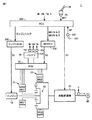
図1は、ハイブリッド車両1(以下、単に車両1と記載する)の構成を示す図である。図1に示すように、車両1は、エンジン10と、第1モータジェネレータ(以下、第1MGと記載する)20と、第2モータジェネレータ(以下、第2MGと記載する)30と、動力分割装置40と、自動変速機50と、PCU(Power Control Unit)60と、バッテリ70と、駆動輪80と、ECU(Electronic Control Unit)200と、エンジンECU250と、MGECU252とを含む。
FIG. 1 is a diagram showing a configuration of a hybrid vehicle 1 (hereinafter simply referred to as a vehicle 1). As shown in FIG. 1, a
車両1は、エンジン10および第2MG30のうちの少なくとも一方から出力される駆動力によって走行する。エンジン10が発生する動力は、動力分割装置40によって2経路に分割される。2経路のうちの一方の経路は自動変速機50を経由して駆動輪80へ伝達される経路であり、他方の経路は第1MG20へ伝達される経路である。
エンジン10は、インジェクタから噴射された燃料と空気との混合気を、シリンダの燃焼室内で燃焼させて出力軸を回転させる内燃機関である。エンジン10は、エンジンECU250からの制御信号S1に基づいて制御される。
The
第1MG20および第2MG30は、たとえば、三相交流回転電機である。第1MG20および第2MG30は、PCU60によって駆動される。 First MG 20 and second MG 30 are, for example, three-phase AC rotating electric machines. First MG 20 and second MG 30 are driven by PCU 60.
第1MG20は、エンジン10の動力を用いて発電してバッテリ70を充電するジェネレータ(発電装置)としての機能を有する。また、第1MG20は、エンジン10のクランク軸を回転させて、エンジン10を始動させるスタータとしての機能を有する。
第2MG30は、自動変速機50を経由して駆動輪80に駆動力を与える駆動用モータとしての機能を有する。また、第2MG30は、回生制動によって発電してバッテリ70を充電するジェネレータとして機能を有する。
The
動力分割装置40は、サンギヤ、プラネタリギヤおよびリングギヤの3つの回転軸を有する遊星歯車機構である。たとえば、第1MG20のロータがサンギヤに接続され、エンジン10の出力軸がキャリアに接続され、かつ、第2MG30の回転軸(自動変速機50の入力軸)がリングギヤに接続される。これによって、エンジン10と第1MG20と第2MG30とが動力分割装置40に機械的に接続される。
The power split
自動変速機50は、複数の変速段(たとえば、1速〜4速)を有する。自動変速機50は、車両1の状態に応じて1速〜4速を自動的に変更する。自動変速機50は、ECU200からの制御信号S3に基づいて制御される。なお、1速〜4速のうち1速が低速側の変速段(変速比が高い変速段)であって、4速が高速側の変速段(変速比が低い変速段)である。
The
シフトレバー54は、運転者が複数のシフトポジション(たとえば、前進走行ポジション等)のうちのいずれか一つを選択したり、手動変速モードと自動変速モードとを切り替えたり、手動変速モードの選択中に変速段を変更するため操作部材である。
The
PCU60は、バッテリ70からの直流電力を交流電力に変換し、第1MG20または第2MG30を駆動する。また、PCU60は、第1MG20および第2MG30が発電した交流電力を直流電力に変換し、バッテリ70を充電する。PCU60は、たとえば、インバータとコンバータとを含むように構成される。PCU60は、MGECU252からの制御信号S2に基づいて制御される。
バッテリ70は、蓄電装置であり、再充電可能な直流電源である。バッテリ70としては、たとえば、ニッケル水素やリチウムイオン等の二次電池が用いられる。バッテリ70は、上述したように第1MG20および/または第2MG30により発電された電力を用いて充電される他、外部電源(図示せず)から供給される電力を用いて充電されてもよい。なお、バッテリ70は、二次電池に限らず、直流電圧を生成できるもの、たとえば、キャパシタ、太陽電池、燃料電池等であってもよい。
The
ECU200には、車速センサ14と、シフトポジションセンサ56と、電流センサ152と、電圧センサ154と、電池温度センサ156と、ペダルポジションセンサ162とが接続される。
車速センサ14は、自動変速機50の出力軸に設けられ、車速Vを検出する。シフトポジションセンサ56は、シフトレバー54の位置SHTを検出する。電流センサ152は、バッテリ70の電流IBを検出する。電圧センサ154は、バッテリ70の電圧VBを検出する。電池温度センサ156は、バッテリ70の電池温度TBを検出する。ペダルポジションセンサ162は、アクセルペダル160の踏み込み量APを検出する。これらのセンサは、検出結果を示す信号をECU200に送信する。
The
ECU200は、電流IBと電圧VBと電池温度TBとに基づいてバッテリ70の蓄電量(以下、SOC(State Of Charge)と記載する)を推定する。ECU200は、たとえば、電流IBと電圧VBと電池温度TBとに基づいてOCV(Open Circuit Voltage)を推定し、推定されたOCVと所定のマップとに基づいてバッテリ70のSOCを推定してもよい。あるいは、ECU200は、たとえば、バッテリ70の充電電流と放電電流とを積算することによってバッテリ70のSOCを推定してもよい。
ECU200は、各種センサの検出結果に基づいて車両1の走行状態が所望の状態になるようにエンジンECU250を用いてエンジン10の出力トルク(以下、エンジントルクと記載する)を制御するとともに、MGECU252を用いて第1MG20および第2MG30の各々の出力トルク(以下、第1MGトルクおよび第2MGトルクと記載する)を制御する。なお、ECU200とエンジンECU250とMGECU252とは、一体のECUであってもよい。
The
以上のような構成を有する車両1において、ECU200は、車両1の状態に基づいてバッテリ70のSOCの目標値を決定し、決定された目標値になるように第1MGトルク、第2MGトルクおよびエンジントルクを制御する。
In the
しかしながら、この目標値をたとえば車速Vに基づいて決定すると、車速Vが大きく変化することによって目標値が大きく変化する場合がある。SOCの目標値が大きく変化すると、エンジン10、第1MG20および第2MG30において要求される出力が大きく変化するため、車両においてショック等が発生して、ドライバビリティが損なわれる場合がある。
However, if this target value is determined based on, for example, the vehicle speed V, the target value may change greatly due to a large change in the vehicle speed V. When the SOC target value changes greatly, the output required by the
そこで、本実施の形態においては、ECU200が、運転者の駆動力要求の大きさが小さいときには、駆動力要求の大きさが大きいときに比べて、バッテリ70のSOCの目標値の変化量を制限する点を特徴とする。このようにすると、駆動力要求の大きさが小さいときには、蓄電量の目標値の変化が緩やかになるため、エンジンおよび電動機において要求される出力の変化が緩やかになる。その結果、車両においてショック等の発生を抑制できる。
Therefore, in the present embodiment,
具体的には、ECU200は、自動変速モードが選択されているときには、手動変速モードが選択されているときに比べて、目標値の変化量を制限する。さらに、ECU200は、アクセルペダル160の踏み込み量APが小さいときには、踏み込み量APが大きいときに比べて、目標値の変化量を制限する。
Specifically, the
図2に、本実施の形態に係る車両1に搭載されたECU200の機能ブロック図を示す。ECU200は、基準値算出部202と、制限値算出部204と、目標値算出部206と、電力要求値算出部208と、エンジン制御部210と、MG制御部212とを含む。なお、これらの構成は、プログラム等のソフトウェアにより実現されてもよいし、ハードウェアにより実現されてもよい。
FIG. 2 shows a functional block diagram of
基準値算出部202は、車両1の状態に基づいてバッテリ70のSOCの基準値を算出する。基準値算出部202は、車速Vと車両1のアウトプットトルクとから図3の変速線図上における位置を特定する。
The reference
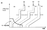
図3の横軸は、車速Vを示す。図3の縦軸は、車両1のアウトプットトルクを示す。図3の変速線図は、複数のアップシフト線(細実線)と、複数のダウンシフト線(破線)とを含む。これらの複数の変速線の各々は、他の変速線と交差しないように設定される。複数の変速線の各々は、アウトプットトルクが低くなるほど変速を開始する車速が低くなるように設定される。さらに、複数のアップシフト線は、アウトプットトルクが一定の場合に、アップシフト後の変速段が大きいアップシフト線であるほどアップシフトを開始する車速が高くなるように設定される。複数のダウンシフト線は、アウトプットトルクが一定の場合に、ダウンシフト後の変速段が小さいダウンシフト線であるほどダウンシフトを開始する車速が低くなるように設定される。図3の太線と縦軸と横軸とで囲まれた領域は、モータ走行域である。モータ走行域では、車両1の走行時に第2MG30より第2MGトルクが自動変速機50に伝達される走行域である。なお、モータ走行域においては、第2MG30のみを駆動源として車両1がEV(Electric Vehicle)走行する場合と、エンジン10と第2MG30とを駆動源として車両1がHV(Hybrid Vehicle)走行する場合とで、同一の変速線(たとえば、図3のモータ走行域内の変速線)が用いられてもよいし、図3のモータ走行域内でEV走行する場合とHV走行する場合とで異なる変速線て用いられてもよい。
The horizontal axis in FIG. 3 indicates the vehicle speed V. The vertical axis in FIG. 3 indicates the output torque of the
基準値算出部202は、車速Vと車両1のアウトプットトルクとから図3の変速線図上の位置が、領域(A)〜(G)のうちのいずれの領域内であるかを特定する。
The reference
図3の変速線図において、領域(A)は、1速←2速のダウンシフト線よりも左側の領域であって、1速が形成される領域である。領域(B)は、1速←2速のダウンシフト線と1速→2速のアップシフト線との間の領域であって、1速および2速のうちのいずれかが形成される領域である。 In the shift diagram of FIG. 3, the region (A) is a region on the left side of the downshift line of the first speed ← second speed and is a region where the first speed is formed. The region (B) is a region between the first-speed ← second-speed downshift line and the first-speed → second-speed upshift line, and is a region where one of the first-speed and second-speed is formed. is there.
領域(C)は、1速→2速のアップシフト線と2速←3速のダウンシフト線との間の領域であって、2速が形成される領域である。領域(D)は、2速←3速のダウンシフト線と2速→3速のアップシフト線との間の領域であって、2速および3速のうちのいずれかが形成される領域である。 Region (C) is a region between the 1st speed → 2nd speed upshift line and the 2nd speed ← 3rd speed downshift line, and is the area where the 2nd speed is formed. Region (D) is a region between the downshift line of the 2nd speed and the 3rd speed and the upshift line of the 2nd speed and the 3rd speed, in which either the 2nd speed or the 3rd speed is formed. is there.
領域(E)は、2速→3速のアップシフト線と3速←4速のダウンシフト線との間の領域であって、3速が形成される領域である。領域(F)は、3速←4速のダウンシフト線と3速→4速のアップシフト線との間の領域であって、3速および4速のうちのいずれかが形成される領域である。 Region (E) is a region between the upshift line of 2nd speed → 3rd speed and the downshift line of 3rd speed ← 4th speed, and is the area where the 3rd speed is formed. Region (F) is a region between the 3rd speed ← 4th speed downshift line and the 3rd speed → 4th speed upshift line, where either 3rd speed or 4th speed is formed. is there.
領域(G)は、3速→4速のアップシフト線よりも右側の領域であって、4速が形成される領域である。 The region (G) is a region on the right side of the upshift line from the third speed to the fourth speed, and is a region where the fourth speed is formed.
基準値算出部202は、アクセルペダル160の踏み込み量APに基づいて算出される要求駆動トルクをアウトプットトルクとして算出する。基準値算出部202は、踏み込み量APに加えて、車速V等を考慮してアウトプットトルクを算出してもよい。基準値算出部202は、たとえば、踏み込み量APと要求駆動トルクとの関係を示す所定のマップを用いてアウトプットトルクを算出してもよい。
The reference
基準値算出部202は、特定された領域に対応する基準値を図4を用いて算出する。図4の横軸は、変速段を示す。図4の縦軸は、基準値を示す。
The reference
図4に示すように、領域(A)〜領域(G)に対して基準値SOC(0)〜SOC(6)がそれぞれ対応づけられる。領域(A)〜領域(G)のうち領域(A)に対応づけられる基準値SOC(0)が最も大きい値であり、領域(G)に対応づけられる基準値SOC(6)が最も小さい値である。また、領域(A)に近い領域に対応づけられる基準値ほど大きくなり、領域(G)に近い領域に対応づけられる基準値ほど小さくなるように基準値SOC(1)〜SOC(5)が設定される。 As shown in FIG. 4, reference values SOC (0) to SOC (6) are associated with regions (A) to (G), respectively. Of the regions (A) to (G), the reference value SOC (0) associated with the region (A) is the largest value, and the reference value SOC (6) associated with the region (G) is the smallest value. It is. In addition, the reference values SOC (1) to SOC (5) are set so that the reference value associated with the region close to the region (A) increases and the reference value associated with the region close to the region (G) decreases. Is done.
そのため、領域(B)に対応する基準値SOC(1)は、領域(A)に対応する基準値SOC(0)と領域(C)に対応する基準値SOC(2)との間の値となる。領域(D)に対応する基準値SOC(3)は、領域(C)に対応する基準値SOC(2)と領域(E)に対応する基準値SOC(4)との間の値となる。領域(F)に対応する基準値SOC(5)は、領域(E)に対応する基準値SOC(4)と領域(G)に対応する基準値SOC(6)との間の値となる。 Therefore, the reference value SOC (1) corresponding to the region (B) is a value between the reference value SOC (0) corresponding to the region (A) and the reference value SOC (2) corresponding to the region (C). Become. The reference value SOC (3) corresponding to the region (D) is a value between the reference value SOC (2) corresponding to the region (C) and the reference value SOC (4) corresponding to the region (E). The reference value SOC (5) corresponding to the region (F) is a value between the reference value SOC (4) corresponding to the region (E) and the reference value SOC (6) corresponding to the region (G).
基準値算出部202は、領域(A)〜(G)のうちの特定された領域に対応する基準値を図4を用いて算出する。
The reference
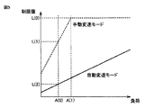
制限値算出部204は、車両1における負荷(走行パワー)に基づいてバッテリ70のSOCの目標値の変化量の制限値を算出する。具体的には、制限値算出部204は、車速Vと要求駆動トルクとに基づいて車両1における負荷を算出する。制限値算出部204は、算出された負荷の値と図5に示すような所定のマップとを用いて制限値を算出する。
Limit
図5の横軸は、車両1における負荷を示す。図5の縦軸は、制限値を示す。図5の実線は、自動変速モードの選択中における負荷と制限値との関係を示す。図5の実線に示すように、自動変速モードの選択中における負荷と制限値との関係は、負荷が大きくなるほど制限値が大きくなる(制限がかかりにくくなる)線形の関係を有する。なお、当該関係は、線形の関係に限定されるものではなく、非線形の関係であってもよい。
The horizontal axis in FIG. 5 indicates the load in the
図5の破線は、手動変速モードの選択中における負荷と制限値との関係を示す。図5の破線に示すように、手動変速モードの選択中における負荷と制限値との関係は、負荷が所定値A(1)になるまでは、負荷が大きくなるほど制限値が大きくなる線形の関係を有する。なお、当該関係についても同様に線形の関係に限定されるものではない。 The broken line in FIG. 5 shows the relationship between the load and the limit value during selection of the manual transmission mode. As shown by the broken line in FIG. 5, the relationship between the load and the limit value during selection of the manual transmission mode is a linear relationship in which the limit value increases as the load increases until the load reaches the predetermined value A (1). Have The relationship is not limited to a linear relationship as well.
また、手動変速モードの選択中における負荷と制限値との関係は、負荷が所定値A(1)よりも大きくなる場合には、負荷の大きさに関わらず制限値が所定値L(0)となる関係を有する。 Further, the relationship between the load and the limit value during selection of the manual shift mode is such that when the load is greater than the predetermined value A (1), the limit value is the predetermined value L (0) regardless of the magnitude of the load. Have a relationship.
そのため、たとえば、負荷がA(0)である場合を想定すると、手動変速モードの選択中(図5の破線)において算出される制限値L(1)は、自動変速モードの選択中(図5の実線)において算出される制限値L(2)よりも大きい値となる。 Therefore, for example, assuming that the load is A (0), the limit value L (1) calculated while the manual shift mode is selected (broken line in FIG. 5) is the selected automatic shift mode (FIG. 5). This is a value larger than the limit value L (2) calculated in (solid line).
目標値算出部206は、算出された基準値と制限値とに基づいてSOCの目標値を算出する。具体的には、目標値算出部206は、現在の目標値(前回算出された目標値)と基準値との差分を算出する。
Target
目標値算出部206は、算出された差分の大きさが制限値よりも小さい場合には、基準値を新たな目標値(今回の目標値)として算出する。
The target
目標値算出部206は、算出された差分の大きさが制限値よりも大きい場合には、現在の目標値からの変化量を制限値に制限する。すなわち、目標値算出部206は、現在の目標値が基準値よりも小さい場合には、現在の目標値に制限値を加算した値を新たな目標値として算出する。また、目標値算出部206は、現在の目標値が基準値よりも大きい場合には、現在の目標値から制限値を減算した値を新たな目標値として算出する。
When the calculated difference magnitude is larger than the limit value, the target
電力要求値算出部208は、算出された目標値と現在SOCとに基づいて電力要求値を算出する。具体的には、電力要求値算出部208は、算出された目標値と現在SOCとの差に基づくフィードバック制御(たとえば、PI制御)により電力要求値を算出してもよいし、あるいは、算出された目標値と現在SOCとの差分と、差分と電力要求値との関係を示す所定のマップとに基づいて電力要求値を算出するようにしてもよい。
The required power
エンジン制御部210は、要求駆動トルクに基づくエンジン10のエンジントルクの指令値に電力要求値に対応する補正値を加算することによって補正された指令値をエンジンECU250に送信する。エンジンECU250は、受信した指令値に基づいてエンジン10に対する燃料噴射制御、スロットルバルブ制御および点火制御を実行する。
MG制御部212は、電力要求値に応じた第1MGトルクと第2MGトルクとを算出し、算出された第1MGトルクに対応するトルク指令値と、第2MGトルクに対応するトルク指令値とをMGECU252に送信する。MGECU252は、受信したトルク指令値に基づいてPCU60を経由して第1MGトルクおよび第2MGトルクを制御する。
The
図6を参照して、本実施の形態に係る車両1に搭載されたECU200で実行される制御処理について説明する。
With reference to FIG. 6, a control process executed by
ステップ(以下、ステップをSと記載する)100にて、ECU200は、現在の変速段、車速V、アクセルペダル160の踏み込み量AP、選択中の変速モードについての情報をたとえば、ECU200に内蔵するメモリや各種センサ等から取得する。
In step (hereinafter, step is referred to as S) 100,
S102にて、ECU200は、基準値を算出する。S104にて、ECU200は、制限値を算出する。基準値および制限値の算出方法については、上述したとおりであるため、その詳細な説明は繰り返さない。
In S102,
S106にて、ECU200は、算出された基準値と制限値と現在の目標値とに基づいて新たな目標値を算出する。S108にて、ECU200は、算出された目標値と、現在SOCとの差分に応じて電力要求値を算出する。
In S106,
S110にて、ECU200は、算出された電力要求値を考慮してエンジントルクの指令値を補正し、補正された指令値をエンジンECU250に送信するとともに、算出された電力要求値に応じた第1MGトルクのトルク指令値と、第2MGトルクのトルク指令値とをMGECU252に送信する。
In S110,
以上のような構造およびフローチャートに基づく本実施の形態に係る車両1に搭載されたECU200の動作について図7を参照して説明する。
An operation of
図7に示すように、現在SOCがSOC(7)(図7の上段の一点鎖線)であって、2速が形成されており、かつ、領域(C)に対応する基準値SOC(2)を目標値としている場合を想定する。また、アクセルペダル160の踏み込み量APが略ゼロである場合を想定する。さらに、自動変速モードが選択されている場合を想定する。なお、現在SOCは、説明の便宜上変速前後で変化しないものとして説明する。
As shown in FIG. 7, the current SOC is SOC (7) (the one-dot chain line in the upper stage of FIG. 7), the second speed is formed, and the reference value SOC (2) corresponding to the region (C) Is assumed to be the target value. Further, it is assumed that the depression amount AP of the
現在SOCは、目標値SOC(2)よりも高いため、電流要求値としては放電側の値となる。また、踏み込み量APは、略ゼロであるため、第2MG30においては、回生も力行も行なわれない。一方、踏み込み量APが略ゼロである場合に対応した車両1の減速度は、第1MGトルクやエンジン10のフリクションロスを利用して実現される。このとき、第1MGトルクの出力値は、車両1の走行状態によって放電側の値P(0)となる場合を想定する。このとき、エンジン10は、一定の回転数となる状態であるものとする。
Since the current SOC is higher than the target value SOC (2), the current request value is a value on the discharge side. Further, since the depression amount AP is substantially zero, neither regeneration nor power running is performed in the
時間T(0)にて、運転者がアクセルペダル160の踏み込み量APを略ゼロからAP(0)まで増加させることによって、車両1の走行状態に基づく図3の変速線図上の位置が領域(C)から領域(A)に移動すると、2速から1速へのダウンシフトが実行される。
At time T (0), the driver increases the depression amount AP of the
このとき、現在の変速段、車速V、アクセルペダル160の踏み込み量AP、選択中の変速モードについての情報がECU200に内蔵するメモリや各種センサから取得される(S100)。
At this time, information on the current shift speed, the vehicle speed V, the depression amount AP of the
そして、領域(A)に対応する基準値SOC(0)が算出される(S102)。また、車速Vと、要求駆動トルクとから算出される負荷と、図5の実線に示すマップとから制限値LMが算出される(S104)。 Then, a reference value SOC (0) corresponding to the region (A) is calculated (S102). Further, the limit value LM is calculated from the load calculated from the vehicle speed V and the required drive torque and the map shown by the solid line in FIG. 5 (S104).
図7の上段の実線に示すように、変速前の目標値SOC(2)と変速後の基準値SOC(0)との差分ΔSOCの大きさが制限値LMを超える場合には、変速前の目標値SOC(2)に算出された制限値LMを加算した値SOC(8)(図7の上段の太破線)が新たな目標値として算出される。 As shown by the solid line in the upper stage of FIG. 7, when the difference ΔSOC between the target value SOC (2) before the shift and the reference value SOC (0) after the shift exceeds the limit value LM, A value SOC (8) obtained by adding the calculated limit value LM to the target value SOC (2) (the thick broken line in the upper part of FIG. 7) is calculated as a new target value.
目標値SOC(8)は、現在SOCよりも高いため電力要求値としては充電側の値が算出される。そのため、第1MG20の出力値は、充電側の値P(1)になる。また、目標値SOC(8)に制限されることによって、現在SOCと目標値SOC(8)との差が現在SOCと基準値SOC(0)との差よりも小さくなる。そのため、第1MG20の出力値P(1)の大きさ(絶対値)は、基準値SOC(0)を目標値とした場合の出力値P(2)の大きさよりも小さい値となる。
Since the target value SOC (8) is higher than the current SOC, a value on the charging side is calculated as the required power value. Therefore, the output value of the
そのため、基準値SOC(0)を目標値とした場合と、目標値をSOC(8)に制限した場合とで比較した場合、時間T(1)以降において、基準値SOC(0)を目標値とした場合の方がバッテリ70の充電量が大きくなるため、図7の下段の実線に示すようにエンジン10の回転数は、目標値をSOC(8)に制限した場合のエンジン10の回転数の変化(図7の下段の破線)よりも一時的に大きく変化する。すなわち、目標値をSOC(8)に制限した場合の方が基準値SOC(0)を目標値として場合よりもエンジン10の回転数の上昇が緩やかになる。
Therefore, when the reference value SOC (0) is set as the target value and when the target value is limited to the SOC (8), the reference value SOC (0) is set to the target value after time T (1). In this case, the amount of charge of the
以上のようにして、本実施の形態に係る車両1によると、アクセルペダル160の踏み込み量APに基づいて算出される負荷(すなわち、運転者の駆動力要求の大きさ)が小さいときには、負荷が大きいときに比べて、SOCの目標値の変化量が制限される。これにより、たとえば、負荷が小さいときには、SOCの目標値の変化が緩やかになる。そのため、エンジン10、第1MG20および第2MG30電動機において要求される出力の変化が緩やかになる。その結果、車両1においてショック等の発生を抑制できる。一方、負荷が大きいときには、SOCの目標値の変化により車両1に生じるショック等は、負荷が大きいことによる他の要因により生じるショック等に紛れるため、負荷が小さいときよりもSOCの目標値の変化が許容される。これによって、バッテリ70のSOCを目標値に従って適切に制御することができるため、燃費の向上が図れる。したがって、蓄電装置の蓄電量の目標値を適切に変化させてトルクショックやノイズなどの発生を抑制するハイブリッド車両を提供することができる。
As described above, according to the
さらに、自動変速モードが選択されているときには、手動変速モードが選択されているときに比べて、SOCの目標値の変化量が制限される。手動変速モードは、運転者が大きな駆動力を必要とする際に選択されることが多い。そのため、手動変速モードの選択中は、目標値の変化により生じるショック等は、他の要因により生じるショック等に紛れるため、自動変速モードの選択中よりも目標値の変化が許容される。これによって、バッテリ70のSOCを目標値に従って適切に制御することができるため、燃費の向上が図れる。
Furthermore, when the automatic transmission mode is selected, the amount of change in the SOC target value is limited compared to when the manual transmission mode is selected. The manual transmission mode is often selected when the driver needs a large driving force. Therefore, during the selection of the manual shift mode, a shock or the like caused by a change in the target value is mixed with a shock or the like caused by other factors, so that the change of the target value is allowed more than during the selection of the automatic shift mode. As a result, the SOC of the
さらに、複数の変速段の各々に基づいてSOCの目標値が決定されるため、車速と運転者が要求する駆動力の大きさとに応じた目標値を決定することができる。 Further, since the SOC target value is determined based on each of the plurality of shift speeds, it is possible to determine the target value according to the vehicle speed and the magnitude of the driving force requested by the driver.
さらに車両1の走行状態に基づいて特定される図3の変速線図上の位置が、たとえば、1速が形成される領域(A)と、2速が形成される領域(C)との間の領域(B)内である場合には、領域(A)に対応した基準値SOC(0)と、領域(C)に対応した基準値SOC(2)との間の値SOC(1)をSOCの基準値として決定される。これにより、1速にダウンシフトされる前あるいは2速にアップシフトされる前にSOCの目標値を変速後の変速段に対応する目標値に近づけることができるので、その後に2速へのアップシフトあるいは1速へのダウンシフトが開始される場合に目標値が大きく変化することを抑制できる。
Further, the position on the shift diagram of FIG. 3 specified based on the traveling state of the
以下変形例について説明する。実施の形態において、変速後に目標値が制限された場合に次の変速が行なわれるまで制限が継続されるものとして説明したが、変速後に制限された目標値を所定時間経過後に所定の変化量であるいは段階的に変速後の変速段に対応する目標値まで変化させるようにしてもよい。 Hereinafter, modifications will be described. In the embodiment, it has been described that when the target value is limited after the shift, the limitation is continued until the next shift is performed. However, the target value limited after the shift is changed to a predetermined change amount after a predetermined time has elapsed. Or you may make it change to the target value corresponding to the gear stage after gear shifting in steps.
本実施の形態に係る車両1においては、自動変速機50は、有段式変速機として説明したが、たとえば、自動変速機50に代えて手動変速機を有するものであってもよいし、複数の変速段として離散的な複数の変速比が設定された無段変速機を有するものであってもよい。
In the
本実施の形態に係る車両1においては、変速段に応じて目標値を決定するものとして説明したが、特にこれに限定されるものではない。たとえば、車両1が上述の無段変速機を有する場合に、選択された変速比に応じて目標値を決定するものであってもよい。
In the
本実施の形態に係る車両1は、図1に示すハイブリッド車両の構成を一例として説明したが、特にこのような構成に限定されるものではなく、たとえば、シリーズ形式のハイブリッド車両であってもよいし、パラレル形式のハイブリッド車両であってもよい。なお、上記した変形例は、その全部または一部を組み合わせて実施してもよい。
The
今回開示された実施の形態はすべての点で例示であって制限的なものではないと考えられるべきである。本発明の範囲は上記した説明ではなくて特許請求の範囲によって示され、特許請求の範囲と均等の意味および範囲内でのすべての変更が含まれることが意図される。 The embodiment disclosed this time should be considered as illustrative in all points and not restrictive. The scope of the present invention is defined by the terms of the claims, rather than the description above, and is intended to include any modifications within the scope and meaning equivalent to the terms of the claims.
1 車両、10 エンジン、14 車速センサ、20,30 MG、40 動力分割装置、50 自動変速機、54 シフトレバー、56 シフトポジションセンサ、60 PCU、70 バッテリ、80 駆動輪、152 電流センサ、154 電圧センサ、156 電池温度センサ、160 アクセルペダル、162 ペダルポジションセンサ、200 ECU、202 基準値算出部、204 制限値算出部、206 目標値算出部、208 電力要求値算出部、210 エンジン制御部、212 エンジン制御部。 1 vehicle, 10 engine, 14 vehicle speed sensor, 20, 30 MG, 40 power split device, 50 automatic transmission, 54 shift lever, 56 shift position sensor, 60 PCU, 70 battery, 80 drive wheels, 152 current sensor, 154 voltage Sensor, 156 Battery temperature sensor, 160 Accelerator pedal, 162 Pedal position sensor, 200 ECU, 202 Reference value calculation unit, 204 Limit value calculation unit, 206 Target value calculation unit, 208 Power requirement value calculation unit, 210 Engine control unit, 212 Engine control unit.
Claims (6)
前記電動機との間で電力を授受する蓄電装置と、
前記蓄電装置の充電に用いられるエンジンと、
車両の状態に基づいて前記蓄電装置の蓄電量の目標値を決定し、前記目標値になるように前記蓄電装置の蓄電量を制御する制御装置とを備え、
前記制御装置は、運転者の駆動力要求の大きさが小さいときには、前記駆動力要求の大きさが大きいときに比べて、前記目標値の変化量を制限する、ハイブリッド車両。 An electric motor capable of transmitting power to the wheels;
A power storage device that exchanges power with the electric motor;
An engine used for charging the power storage device;
A control device that determines a target value of a power storage amount of the power storage device based on a state of the vehicle and controls the power storage amount of the power storage device so as to be the target value;
The control device limits the amount of change in the target value when the magnitude of the driving force demand of the driver is small compared to when the magnitude of the driving power demand is large.
前記制御装置は、前記変速機で形成される変速比に基づいて前記目標値を決定し、前記目標値になるように前記蓄電量を制御する、請求項1に記載のハイブリッド車両。2. The hybrid vehicle according to claim 1, wherein the control device determines the target value based on a gear ratio formed by the transmission, and controls the storage amount so as to be the target value.
前記制御装置は、前記自動変速モードが選択されているときには、前記手動変速モードが選択されているときに比べて、前記変化量を制限する、請求項1または2に記載のハイブリッド車両。 The vehicle further includes an automatic transmission having an automatic transmission mode and a manual transmission mode,
Wherein the controller, when the automatic shift mode is selected, the manual than when the shift mode is selected, limiting the amount of change, the hybrid vehicle according to claim 1 or 2.
前記制御装置は、前記踏み込み量が小さいときには、前記踏み込み量が大きいときに比べて、前記変化量を制限する、請求項1または2に記載のハイブリッド車両。 The vehicle further includes a detection device that detects a depression amount of an accelerator pedal,
Wherein the controller, when the depression amount is small, than when the depression amount is large, limiting the amount of change, the hybrid vehicle according to claim 1 or 2.
前記制御装置は、前記有段式変速機の変速段に基づいて前記目標値を決定する、請求項1〜4のいずれかに記載のハイブリッド車両。 The vehicle further includes a stepped transmission,
The hybrid vehicle according to any one of claims 1 to 4 , wherein the control device determines the target value based on a gear position of the stepped transmission.
前記制御装置は、前記走行状態が前記アップシフト領域と前記ダウンシフト領域との間の領域内である場合には、前記第1変速段に対応する前記蓄電量の第1目標値と、前記第2変速段に対応する前記蓄電量の第2目標値との間の値を前記蓄電量の前記目標値として決定する、請求項5に記載のハイブリッド車両。 In the stepped transmission, when the running state of the vehicle enters the upshift region from outside the upshift region, an upshift from the first gear to the second gear is started, and the traveling When the state enters the downshift region from outside the downshift region, a downshift from the second gear to the first gear is started,
When the traveling state is in a region between the upshift region and the downshift region, the control device includes a first target value of the storage amount corresponding to the first gear, and the first The hybrid vehicle according to claim 5 , wherein a value between the second target value of the charged amount corresponding to the second shift stage is determined as the target value of the charged amount.
Priority Applications (3)
| Application Number | Priority Date | Filing Date | Title |
|---|---|---|---|
| JP2014059960A JP6149772B2 (en) | 2014-03-24 | 2014-03-24 | Hybrid vehicle |
| US14/628,551 US9604626B2 (en) | 2014-03-24 | 2015-02-23 | Hybrid vehicle |
| CN201510126475.XA CN104943527A (en) | 2014-03-24 | 2015-03-23 | Hybrid vehicle |
Applications Claiming Priority (1)
| Application Number | Priority Date | Filing Date | Title |
|---|---|---|---|
| JP2014059960A JP6149772B2 (en) | 2014-03-24 | 2014-03-24 | Hybrid vehicle |
Publications (2)
| Publication Number | Publication Date |
|---|---|
| JP2015182554A JP2015182554A (en) | 2015-10-22 |
| JP6149772B2 true JP6149772B2 (en) | 2017-06-21 |
Family
ID=54141332
Family Applications (1)
| Application Number | Title | Priority Date | Filing Date |
|---|---|---|---|
| JP2014059960A Expired - Fee Related JP6149772B2 (en) | 2014-03-24 | 2014-03-24 | Hybrid vehicle |
Country Status (3)
| Country | Link |
|---|---|
| US (1) | US9604626B2 (en) |
| JP (1) | JP6149772B2 (en) |
| CN (1) | CN104943527A (en) |
Families Citing this family (9)
| Publication number | Priority date | Publication date | Assignee | Title |
|---|---|---|---|---|
| DE102010042183A1 (en) * | 2010-10-08 | 2012-04-12 | Robert Bosch Gmbh | Hybrid drive device |
| CN106853828B (en) * | 2015-12-08 | 2019-07-02 | 上海汽车集团股份有限公司 | Control method for vehicle, apparatus and system |
| JP6520884B2 (en) * | 2016-10-12 | 2019-05-29 | トヨタ自動車株式会社 | Vehicle control device |
| JP6683593B2 (en) * | 2016-12-19 | 2020-04-22 | トヨタ自動車株式会社 | Control device for hybrid vehicle |
| JP6551381B2 (en) * | 2016-12-20 | 2019-07-31 | トヨタ自動車株式会社 | Control device for hybrid vehicle |
| CN109703371B (en) * | 2018-12-06 | 2022-02-01 | 奇瑞汽车股份有限公司 | High-voltage energy management system and method for electric automobile |
| CN109823188A (en) * | 2019-01-10 | 2019-05-31 | 乾碳国际公司 | The mixed gentle speed system of dynamic commercial vehicle regenerative braking |
| JP7163818B2 (en) * | 2019-02-26 | 2022-11-01 | トヨタ自動車株式会社 | Hybrid vehicle control device |
| JP7416188B1 (en) | 2022-12-21 | 2024-01-17 | トヨタ自動車株式会社 | Electric car |
Family Cites Families (19)
| Publication number | Priority date | Publication date | Assignee | Title |
|---|---|---|---|---|
| JP3909695B2 (en) * | 2002-12-27 | 2007-04-25 | アイシン・エィ・ダブリュ株式会社 | Vehicle control device |
| US7032393B2 (en) * | 2003-08-28 | 2006-04-25 | General Motors Corporation | Climate cooling control systems and methods for hybrid vehicles |
| JP4345765B2 (en) * | 2006-03-30 | 2009-10-14 | トヨタ自動車株式会社 | Vehicle and control method thereof |
| JP4345824B2 (en) * | 2007-02-21 | 2009-10-14 | トヨタ自動車株式会社 | Vehicle and control method thereof |
| JP2008260361A (en) * | 2007-04-11 | 2008-10-30 | Denso Corp | Vehicular control apparatus |
| US7766109B2 (en) * | 2007-09-28 | 2010-08-03 | Gm Global Technology Operations, Inc. | Hybrid powertrains and methods of operating |
| JP4407741B2 (en) * | 2007-11-21 | 2010-02-03 | トヨタ自動車株式会社 | Vehicle and control method thereof |
| JP2010013002A (en) * | 2008-07-04 | 2010-01-21 | Toyota Motor Corp | Hybrid drive apparatus and drive control device |
| JP2011121413A (en) * | 2009-12-08 | 2011-06-23 | Honda Motor Co Ltd | Hybrid vehicle |
| RU2518144C2 (en) * | 2009-12-08 | 2014-06-10 | Хонда Мотор Ко., Лтд. | Hybrid vehicle |
| JP2012066624A (en) | 2010-09-21 | 2012-04-05 | Suzuki Motor Corp | Power generation control device for electric vehicle |
| DE112010006004T5 (en) * | 2010-11-17 | 2013-08-29 | Toyota Jidosha Kabushiki Kaisha | Charging and discharging control device and method |
| WO2012114430A1 (en) * | 2011-02-21 | 2012-08-30 | スズキ株式会社 | Hybrid vehicle drive control device |
| JP5747724B2 (en) * | 2011-08-04 | 2015-07-15 | トヨタ自動車株式会社 | Vehicle and vehicle control method |
| JP5917866B2 (en) * | 2011-09-12 | 2016-05-18 | トヨタ自動車株式会社 | Vehicle control device |
| JP2013063736A (en) * | 2011-09-20 | 2013-04-11 | Toyota Motor Corp | Hybrid vehicle control device |
| US9074683B2 (en) * | 2011-11-09 | 2015-07-07 | Toyota Jidosha Kabushiki Kaisha | Gear shift indication device |
| US9045136B2 (en) * | 2013-02-08 | 2015-06-02 | Efficient Drivetrains, Inc. | Systems and methods for implementing dynamic operating modes and control policies for hybrid electric vehicles |
| US9126581B2 (en) * | 2013-05-08 | 2015-09-08 | GM Global Technology Operations LLC | Hybrid powertrain and modular rear drive unit for same |
-
2014
- 2014-03-24 JP JP2014059960A patent/JP6149772B2/en not_active Expired - Fee Related
-
2015
- 2015-02-23 US US14/628,551 patent/US9604626B2/en active Active
- 2015-03-23 CN CN201510126475.XA patent/CN104943527A/en active Pending
Also Published As
| Publication number | Publication date |
|---|---|
| CN104943527A (en) | 2015-09-30 |
| US20150266465A1 (en) | 2015-09-24 |
| US9604626B2 (en) | 2017-03-28 |
| JP2015182554A (en) | 2015-10-22 |
Similar Documents
| Publication | Publication Date | Title |
|---|---|---|
| JP6149772B2 (en) | Hybrid vehicle | |
| CN107161139B (en) | Hybrid vehicle and control method for hybrid vehicle | |
| US10543829B2 (en) | Hybrid vehicle including electronic control unit configured to correct base driving force using correction driving force | |
| US9994214B2 (en) | Hybrid vehicle | |
| US10046755B2 (en) | Hybrid vehicle | |
| JP6458770B2 (en) | Hybrid car | |
| US10279794B2 (en) | Hybrid vehicle | |
| US11052900B2 (en) | Hybrid vehicle | |
| JP2007283878A (en) | Power transmission device, automobile mounted therewith, and control method of power transmission device | |
| JP2019085002A (en) | Hybrid-vehicle control apparatus | |
| US20170072939A1 (en) | Hybrid vehicle | |
| US9574504B2 (en) | Vehicle and control method for the vehicle | |
| JP6269589B2 (en) | Electric vehicle | |
| US20170166184A1 (en) | Control system for power transmission system | |
| JP6512173B2 (en) | Hybrid car | |
| JP6062804B2 (en) | vehicle | |
| JP2021031034A (en) | Hybrid vehicle | |
| JP2019177712A (en) | Hybrid vehicle | |
| JP2021031038A (en) | Hybrid vehicle | |
| JP2019111854A (en) | Hybrid vehicle | |
| JP2018007372A (en) | Automobile |
Legal Events
| Date | Code | Title | Description |
|---|---|---|---|
| A977 | Report on retrieval |
Free format text: JAPANESE INTERMEDIATE CODE: A971007 Effective date: 20160216 |
|
| A131 | Notification of reasons for refusal |
Free format text: JAPANESE INTERMEDIATE CODE: A131 Effective date: 20160223 |
|
| A131 | Notification of reasons for refusal |
Free format text: JAPANESE INTERMEDIATE CODE: A131 Effective date: 20160920 |
|
| A521 | Request for written amendment filed |
Free format text: JAPANESE INTERMEDIATE CODE: A523 Effective date: 20161118 |
|
| TRDD | Decision of grant or rejection written | ||
| A01 | Written decision to grant a patent or to grant a registration (utility model) |
Free format text: JAPANESE INTERMEDIATE CODE: A01 Effective date: 20170425 |
|
| A61 | First payment of annual fees (during grant procedure) |
Free format text: JAPANESE INTERMEDIATE CODE: A61 Effective date: 20170508 |
|
| R151 | Written notification of patent or utility model registration |
Ref document number: 6149772 Country of ref document: JP Free format text: JAPANESE INTERMEDIATE CODE: R151 |
|
| LAPS | Cancellation because of no payment of annual fees |