WO2011083795A1 - 無線基地局装置、移動端末装置及び無線通信方法 - Google Patents
無線基地局装置、移動端末装置及び無線通信方法 Download PDFInfo
- Publication number
- WO2011083795A1 WO2011083795A1 PCT/JP2011/050036 JP2011050036W WO2011083795A1 WO 2011083795 A1 WO2011083795 A1 WO 2011083795A1 JP 2011050036 W JP2011050036 W JP 2011050036W WO 2011083795 A1 WO2011083795 A1 WO 2011083795A1
- Authority
- WO
- WIPO (PCT)
- Prior art keywords
- reference signal
- channel quality
- quality measurement
- measurement reference
- base station
- Prior art date
- Legal status (The legal status is an assumption and is not a legal conclusion. Google has not performed a legal analysis and makes no representation as to the accuracy of the status listed.)
- Ceased
Links
Images

Classifications
-
- H—ELECTRICITY
- H04—ELECTRIC COMMUNICATION TECHNIQUE
- H04L—TRANSMISSION OF DIGITAL INFORMATION, e.g. TELEGRAPHIC COMMUNICATION
- H04L5/00—Arrangements affording multiple use of the transmission path
- H04L5/003—Arrangements for allocating sub-channels of the transmission path
- H04L5/0053—Allocation of signalling, i.e. of overhead other than pilot signals
-
- H—ELECTRICITY
- H04—ELECTRIC COMMUNICATION TECHNIQUE
- H04B—TRANSMISSION
- H04B17/00—Monitoring; Testing
- H04B17/30—Monitoring; Testing of propagation channels
- H04B17/309—Measuring or estimating channel quality parameters
- H04B17/336—Signal-to-interference ratio [SIR] or carrier-to-interference ratio [CIR]
-
- H—ELECTRICITY
- H04—ELECTRIC COMMUNICATION TECHNIQUE
- H04B—TRANSMISSION
- H04B17/00—Monitoring; Testing
- H04B17/30—Monitoring; Testing of propagation channels
- H04B17/309—Measuring or estimating channel quality parameters
- H04B17/345—Interference values
-
- H—ELECTRICITY
- H04—ELECTRIC COMMUNICATION TECHNIQUE
- H04J—MULTIPLEX COMMUNICATION
- H04J11/00—Orthogonal multiplex systems, e.g. using WALSH codes
- H04J11/0023—Interference mitigation or co-ordination
- H04J11/0026—Interference mitigation or co-ordination of multi-user interference
-
- H—ELECTRICITY
- H04—ELECTRIC COMMUNICATION TECHNIQUE
- H04J—MULTIPLEX COMMUNICATION
- H04J11/00—Orthogonal multiplex systems, e.g. using WALSH codes
- H04J11/0023—Interference mitigation or co-ordination
- H04J11/0026—Interference mitigation or co-ordination of multi-user interference
- H04J11/003—Interference mitigation or co-ordination of multi-user interference at the transmitter
-
- H—ELECTRICITY
- H04—ELECTRIC COMMUNICATION TECHNIQUE
- H04L—TRANSMISSION OF DIGITAL INFORMATION, e.g. TELEGRAPHIC COMMUNICATION
- H04L1/00—Arrangements for detecting or preventing errors in the information received
- H04L1/20—Arrangements for detecting or preventing errors in the information received using signal quality detector
-
- H—ELECTRICITY
- H04—ELECTRIC COMMUNICATION TECHNIQUE
- H04L—TRANSMISSION OF DIGITAL INFORMATION, e.g. TELEGRAPHIC COMMUNICATION
- H04L5/00—Arrangements affording multiple use of the transmission path
- H04L5/003—Arrangements for allocating sub-channels of the transmission path
- H04L5/0048—Allocation of pilot signals, i.e. of signals known to the receiver
- H04L5/0051—Allocation of pilot signals, i.e. of signals known to the receiver of dedicated pilots, i.e. pilots destined for a single user or terminal
-
- H—ELECTRICITY
- H04—ELECTRIC COMMUNICATION TECHNIQUE
- H04L—TRANSMISSION OF DIGITAL INFORMATION, e.g. TELEGRAPHIC COMMUNICATION
- H04L5/00—Arrangements affording multiple use of the transmission path
- H04L5/003—Arrangements for allocating sub-channels of the transmission path
- H04L5/0058—Allocation criteria
- H04L5/0073—Allocation arrangements that take into account other cell interferences
-
- H—ELECTRICITY
- H04—ELECTRIC COMMUNICATION TECHNIQUE
- H04W—WIRELESS COMMUNICATION NETWORKS
- H04W24/00—Supervisory, monitoring or testing arrangements
- H04W24/10—Scheduling measurement reports ; Arrangements for measurement reports
-
- H—ELECTRICITY
- H04—ELECTRIC COMMUNICATION TECHNIQUE
- H04W—WIRELESS COMMUNICATION NETWORKS
- H04W28/00—Network traffic management; Network resource management
- H04W28/02—Traffic management, e.g. flow control or congestion control
- H04W28/04—Error control
-
- H—ELECTRICITY
- H04—ELECTRIC COMMUNICATION TECHNIQUE
- H04W—WIRELESS COMMUNICATION NETWORKS
- H04W48/00—Access restriction; Network selection; Access point selection
- H04W48/08—Access restriction or access information delivery, e.g. discovery data delivery
-
- H—ELECTRICITY
- H04—ELECTRIC COMMUNICATION TECHNIQUE
- H04W—WIRELESS COMMUNICATION NETWORKS
- H04W8/00—Network data management
- H04W8/22—Processing or transfer of terminal data, e.g. status or physical capabilities
- H04W8/24—Transfer of terminal data
-
- H—ELECTRICITY
- H04—ELECTRIC COMMUNICATION TECHNIQUE
- H04J—MULTIPLEX COMMUNICATION
- H04J11/00—Orthogonal multiplex systems, e.g. using WALSH codes
- H04J11/0023—Interference mitigation or co-ordination
- H04J11/005—Interference mitigation or co-ordination of intercell interference
- H04J11/0059—Out-of-cell user aspects
-
- H—ELECTRICITY
- H04—ELECTRIC COMMUNICATION TECHNIQUE
- H04L—TRANSMISSION OF DIGITAL INFORMATION, e.g. TELEGRAPHIC COMMUNICATION
- H04L5/00—Arrangements affording multiple use of the transmission path
- H04L5/0001—Arrangements for dividing the transmission path
- H04L5/0014—Three-dimensional division
- H04L5/0023—Time-frequency-space
-
- H—ELECTRICITY
- H04—ELECTRIC COMMUNICATION TECHNIQUE
- H04L—TRANSMISSION OF DIGITAL INFORMATION, e.g. TELEGRAPHIC COMMUNICATION
- H04L5/00—Arrangements affording multiple use of the transmission path
- H04L5/003—Arrangements for allocating sub-channels of the transmission path
- H04L5/0037—Inter-user or inter-terminal allocation
- H04L5/0039—Frequency-contiguous, i.e. with no allocation of frequencies for one user or terminal between the frequencies allocated to another
-
- H—ELECTRICITY
- H04—ELECTRIC COMMUNICATION TECHNIQUE
- H04L—TRANSMISSION OF DIGITAL INFORMATION, e.g. TELEGRAPHIC COMMUNICATION
- H04L5/00—Arrangements affording multiple use of the transmission path
- H04L5/003—Arrangements for allocating sub-channels of the transmission path
- H04L5/0053—Allocation of signalling, i.e. of overhead other than pilot signals
- H04L5/0057—Physical resource allocation for CQI
-
- H—ELECTRICITY
- H04—ELECTRIC COMMUNICATION TECHNIQUE
- H04L—TRANSMISSION OF DIGITAL INFORMATION, e.g. TELEGRAPHIC COMMUNICATION
- H04L5/00—Arrangements affording multiple use of the transmission path
- H04L5/003—Arrangements for allocating sub-channels of the transmission path
- H04L5/0078—Timing of allocation
- H04L5/0082—Timing of allocation at predetermined intervals
-
- H—ELECTRICITY
- H04—ELECTRIC COMMUNICATION TECHNIQUE
- H04W—WIRELESS COMMUNICATION NETWORKS
- H04W88/00—Devices specially adapted for wireless communication networks, e.g. terminals, base stations or access point devices
- H04W88/08—Access point devices
Definitions
- the present invention relates to a radio base station apparatus, a mobile terminal apparatus, and a radio communication method.
- the reference signal is arranged to:: (RB Resource Block) ( Reference Signal RS) resource blocks.
- RB Resource Block Reference Signal RS
- the downlink signal can be synchronously detected by receiving the reference signal in the mobile terminal device (Non-patent Document 1).
- the reference signal is scrambled (randomized by a known signal sequence) by a cell-specific scrambling signal.
- LTE-A LTE-Advanced
- DM-RS demodulation reference signal
- CSI-RS channel quality measurement reference signal
- the demodulation reference signal is used for demodulation of a physical downlink shared channel (PDSCH). This demodulation reference signal is subjected to precoding similar to PDSCH and transmitted to the mobile terminal apparatus.
- the channel quality measurement reference signal is used to measure channel quality information (Channel State Indicator) that the mobile terminal apparatus feeds back to the radio base station apparatus.
- the LTE-A system requires more accurate interference estimation than the LTE system. Therefore, in the LTE-A system, it is necessary to design the configuration of a downlink channel quality measurement reference signal so as to satisfy such a requirement.
- the present invention has been made in view of this point, and provides a radio base station apparatus, a mobile terminal apparatus, and a radio communication method for transmitting and receiving a downlink channel quality measurement reference signal in consideration of highly accurate interference estimation. For the purpose.
- the radio base station apparatus of the present invention comprises generation means for generating a channel quality measurement reference signal and mapping means for mapping the channel quality measurement reference signal to two adjacent symbols. .
- the radio base station apparatus of the present invention includes a generating unit that generates a channel quality measurement reference signal, a mapping unit that maps the channel quality measurement reference signal to a specific symbol, and a predetermined subcarrier in the specific symbol. And puncturing means for puncturing.
- downlink channel quality measurement reference signals can be transmitted and received in consideration of highly accurate interference estimation.
- (A), (b) is a figure for demonstrating the mapping of CSI-RS which concerns on this invention.
- (A), (b) is a figure for demonstrating the mapping of CSI-RS which concerns on this invention.
- (A)-(c) is a figure for demonstrating the mapping of CSI-RS which concerns on this invention.
- the mobile terminal apparatus estimates a reception propagation channel for a serving cell using a channel quality measurement reference signal (CSI-RS).
- CSI-RS channel quality measurement reference signal
- interference from neighboring cells is estimated using CSI-RS.
- the interference power is obtained from the residual of the two CSI-RSs. If the two CSI-RSs used for estimating the interference power are mapped apart in the frequency domain / time domain, the channel state at each mapping position is different, so the residual of the two CSI-RSs When the interference power is estimated from the above, the interference cannot be estimated with high accuracy.
- the present inventors have considered the arrangement of reference signals for downlink channel quality measurement in consideration of such highly accurate interference estimation, and have completed the present invention.
- the essence of the present invention is to generate a CSI-RS and map this CSI-RS to two adjacent symbols, or generate a CSI-RS and map this CSI-RS to a specific symbol, Puncturing a predetermined subcarrier in this specific symbol.
- the following two modes can be cited as CSI-RS mapping for highly accurate interference estimation.
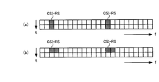
- CSI-RS is mapped to two adjacent symbols.
- the CSI-RS may be mapped to two adjacent symbols in time, and as shown in FIG. 1 (b), two adjacent symbols at the CSI-RS frequency. It may be mapped to.
- the mapping using two symbols adjacent in the time domain as in the former is suitable for application to a low-speed moving environment.
- FIGS. 1A and 1B illustrate a case where CSI-RS is mapped as a pair to two symbols adjacent in frequency or two symbols adjacent in time, but the present invention is not limited to this.
- the CSI-RS may be mapped as a pair to two symbols that are close in frequency or time or two symbols that are adjacent in time.
- the symbols that are close in frequency or time are two symbols that have the same channel state to a sufficient extent to estimate the interference power with high accuracy.
- the channel state at each CSI-RS mapping position becomes substantially equal.
- interference power is estimated from the residuals of two CSI-RSs, interference can be estimated with high accuracy.
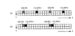
- CSI-RS is mapped to a specific symbol, and a predetermined subcarrier in the specific symbol is punctured. That is, a predetermined subcarrier in an OFDM symbol multiplexed with CSI-RS is punctured.
- a predetermined subcarrier in an OFDM symbol multiplexed with CSI-RS is punctured.
- subcarriers away from the CSI-RS may be punctured
- subcarriers adjacent to (adjacent to) the CSI-RS. May be punctured.
- FIGS. 3A to 3C show an example in which CSI-RS is mapped in the first mode.
- the reference signal arrangement patterns shown in FIGS. 3A to 3C are FDM (Frequency Division Multiplex) or TDM (Time Division Multiplex) arrangement patterns.
- the arrangement pattern shown in FIG. 3 (a) is an arrangement pattern of 24 subcarrier periods
- the arrangement pattern shown in FIG. 3 (b) is an arrangement pattern of 16 subcarrier periods
- the pattern is an arrangement pattern of 12 subcarrier periods.
- the black portion is the Release 8 LTE reference signal portion
- the upward slanted line portion is the Release 10 LTE DM-RS portion
- the upward sloping portion is the present invention.
- It is the CSI-RS part that defines.
- the CSI-RS is mapped to two adjacent symbols in time (CSI-RS pair), and CSI- for eight transmitting antennas (port 0-7).
- RS pairs are mapped to subcarriers.
- CSI-RSs of port 0, 2, 4, 6 are mapped to 4 consecutive subcarriers
- CSI-RS of ports 1, 3, 5, 7 are mapped to 4 consecutive subcarriers.
- mapping CSI-RS to two adjacent symbols, or mapping CSI-RS to a specific symbol and puncturing a predetermined subcarrier in this specific symbol two CSI-RSs
- the interference can be estimated with high accuracy when the interference power is estimated from the residual.
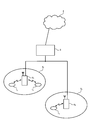
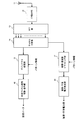
- FIG. 4 is a diagram showing a radio communication system having radio base station apparatuses and mobile terminal apparatuses according to the embodiment of the present invention.
- the wireless communication system is a system to which, for example, E-UTRA (Evolved UTRA and UTRAN) is applied.
- the radio communication system includes a radio base station apparatus (eNB: eNodeB) 2 (2 1 , 2 2 ... 2 l , l is an integer of l> 0) and a plurality of mobile terminal apparatuses that communicate with the radio base station apparatus 2 (UE) 1 n (1 1 , 1 2 , 1 3 ,... 1 n , n is an integer of n> 0).
- the radio base station apparatus 2 is connected to an upper station, for example, an access gateway apparatus 3, and the access gateway apparatus 3 is connected to the core network 4.
- the mobile terminal 1 n communicates with the radio base station apparatus 2 by E-UTRA in the cell 5 (5 1 , 5 2 ).
- the present embodiment shows two cells, the present invention can be similarly applied to three or more cells.
- each mobile terminal device (1 1 , 1 2 , 1 3 ,... 1 n ) has the same configuration, function, and state, the following description will be given as the mobile terminal device 1 n unless otherwise specified. To proceed.
- OFDM Orthogonal Frequency Division Multiple Access
- SC-FDMA Single Carrier Frequency Division Multiple Access
- OFDM is a multi-carrier transmission scheme that performs communication by dividing a frequency band into a plurality of narrow frequency bands (subcarriers) and mapping data to each subcarrier.
- SC-FDMA is a single carrier transmission scheme in which frequency bands are divided for each terminal and a plurality of mobile terminal apparatuses use different frequency bands to reduce interference between mobile terminal apparatuses.
- a physical downlink shared channel (PDSCH) shared by each mobile terminal device 1 n and a physical downlink control channel (PDCCH) are used.
- the physical downlink control channel is also called a downlink L1 / L2 control channel.
- User data that is, a normal data signal is transmitted through the physical downlink shared channel.
- downlink scheduling information DL Scheduling Information
- acknowledgment information ACK / NACK
- uplink scheduling grant UL Scheduling Grant
- TPC command Transmission Power Control Command
- the downlink scheduling information includes, for example, the ID of a user who performs communication using a physical downlink shared channel, and information on the transport format of the user data, that is, data size, modulation scheme, retransmission control (HARQ: Hybrid ARQ). And downlink resource block allocation information.
- HARQ Hybrid ARQ
- the uplink scheduling grant includes, for example, the ID of a user who performs communication using the physical uplink shared channel, information on the transport format of the user data, that is, information on the data size and modulation scheme, This includes resource block allocation information, information related to uplink shared channel transmission power, and the like.
- the uplink resource block corresponds to a frequency resource and is also called a resource unit.
- the delivery confirmation information (ACK / NACK) is delivery confirmation information related to the uplink shared channel.
- the contents of the acknowledgment information are expressed by either an acknowledgment (ACK: Acknowledgement) indicating that the transmission signal has been properly received or a negative acknowledgment (NACK: Negative Acknowledgement) indicating that the transmission signal has not been properly received. Is done.
- a physical uplink shared channel (PUSCH) shared by each mobile terminal device 1 n and a physical uplink control channel (PUCCH) are used.
- User data that is, a normal data signal is transmitted through the physical uplink shared channel.
- the physical uplink control channel transmits downlink quality information and physical downlink shared channel delivery confirmation information to be used for downlink shared physical channel scheduling processing, adaptive modulation / demodulation, and encoding processing.
- a scheduling request for requesting uplink shared channel resource allocation (Scheduling Request), a release request for persistent scheduling (Release Request), etc. May be sent.
- the resource allocation of the uplink shared channel means that the radio base station can perform communication using the uplink shared channel in the subsequent subframe using the physical downlink control channel of a certain subframe. This means that the device notifies the mobile terminal device.
- the mobile terminal apparatus 1 n communicates with the optimal radio base station apparatus.
- the mobile terminal device 1 1, 1 2 communicates with the radio base station apparatus 2 1
- the mobile terminal device 1 3 is communicating with the radio base station apparatus 2 2.
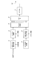
- FIG. 5 is a diagram showing a configuration of the radio base station apparatus according to the embodiment of the present invention. Although only the transmission unit is illustrated in FIG. 5, this radio base station apparatus naturally includes a reception unit that receives and processes an uplink signal.
- the radio base station apparatus shown in FIG. 5 includes a shared channel signal generation unit 21 that generates a shared channel signal, a puncture processing unit 22 that punctures the shared channel signal, and a CSI-RS sequence generation unit that generates a CSI-RS sequence. 23, a time / frequency mapping unit 24 that maps the CSI-RS to the time domain / frequency domain, a channel multiplexing unit 25 that multiplexes the shared channel signal and the signal including the CSI-RS, and IFFT ( An IFFT unit 26 that performs Inverse Fast Fourier Transform, a CP addition unit 27 that adds a CP (Cyclic Prefix) to the signal after IFFT, and a transmission antenna 28 are mainly configured. Note that the radio base station apparatus can perform MIMO transmission using a plurality of transmission antennas, but FIG. 5 shows the configuration of one transmission antenna in order to simplify the description.
- the shared channel signal generation unit 21 generates a shared channel signal (signal transmitted by PDSCH) using downlink transmission data.
- the shared channel signal generation unit 21 generates a shared channel signal based on the CSI measurement value measured by the radio base station apparatus using the CSI-RS included in the uplink signal.
- the shared channel signal generation unit 21 outputs the generated shared channel signal to the puncture processing unit 22.
- the puncture processing unit 22 performs puncture processing on the generated shared channel signal.
- a predetermined subcarrier in an OFDM symbol in which CSI-RS is multiplexed is punctured.
- the predetermined subcarrier to be punctured is based on predetermined pattern information.
- the puncture processing unit 22 outputs the shared channel signal after the puncture processing to the channel multiplexing unit 25.
- the CSI-RS sequence generator 23 generates a CSI-RS to be multiplexed on the RB.
- the CSI-RS sequence generation unit 23 outputs the CSI-RS to the time / frequency mapping unit 24.
- the time / frequency mapping unit 24 maps the CSI-RS to the time domain / frequency domain in the RB.
- the time / frequency mapping unit 24 maps the CSI-RS to two adjacent symbols, or maps the CSI-RS to a specific symbol. That is, in the first mode, the time / frequency mapping unit 24 maps the CSI-RS to two adjacent symbols in time as shown in FIG. 1 (a), or as shown in FIG. 1 (b). Are mapped to two adjacent symbols at the CSI-RS frequency. In the second mode, the time / frequency mapping unit 24 maps the CSI-RS to a specific symbol as shown in FIGS. 2 (a) and 2 (b).
- the RB for mapping the CSI-RS is based on predetermined pattern information.
- the time / frequency mapping unit 24 outputs the mapped signal to the channel multiplexing unit 25.
- the channel multiplexing unit 25 channel-multiplexes the common channel signal and the signal including CSI-RS.
- the channel multiplexing unit 25 outputs the channel multiplexed signal to the IFFT unit 26.
- the IFFT unit 26 performs IFFT on the channel multiplexed signal and converts it into a time domain signal.
- IFFT unit 26 outputs the signal after IFFT to CP adding unit 27.
- CP adding section 27 adds a CP to the signal after IFFT.
- the CP-added signal is transmitted from the transmission antenna 28 to each mobile terminal device on the downlink (downlink physical shared channel).
- FIG. 6 is a diagram showing a configuration of the mobile terminal apparatus according to the embodiment of the present invention.
- the mobile terminal apparatus shown in FIG. 6 includes a receiving antenna 11, a CP removing unit 12 that removes a CP from the received signal, an FFT unit 13 that performs FFT (Fast Fourier Transform) on the CP-removed signal, a shared channel signal, and a CSI.
- FFT Fast Fourier Transform
- a channel dividing unit 14 that divides a signal including RS, a depuncture processing unit 15 that depunctures a shared channel signal, a shared channel signal demodulation / decoding unit 16 that demodulates and decodes the depunctured shared channel signal, and a time
- the time / frequency demapping unit 17 for demapping the CSI-RS mapped in the region / frequency domain, and the noise / interference power estimation unit 18 for estimating the interference power using the demapped CSI-RS are mainly used. It is configured.
- the signal transmitted from the radio base station apparatus on the downlink is received via the reception antenna 11 of the mobile terminal apparatus.
- CP removing section 12 removes the CP from the received signal.
- CP removing section 12 outputs the signal after CP removal to FFT section 13.
- the FFT unit 13 performs FFT on the signal after CP removal and converts it to a frequency domain signal.
- the FFT unit 13 outputs the signal after the FFT to the channel dividing unit 14.
- the channel division unit 14 divides the common channel signal and the signal including CSI-RS into channels.
- the channel division unit 14 outputs the channel-divided signal to the depuncture processing unit 15.
- the depuncture processing unit 15 performs depuncture processing on the shared channel signal that has been divided into channels.
- the depuncture processing unit 15 performs depuncture processing on the shared channel signal based on the pattern information.
- the shared channel signal after the depuncture process is output to the shared channel signal demodulation / decoding unit 16.
- the pattern information may be notified from the radio base station apparatus to the mobile terminal apparatus via a broadcast channel (BCH), may be transmitted as an L1 / L2 control signal, and is notified by an upper layer. Also good.
- the shared channel signal demodulation / decoding unit 16 demodulates and decodes the depunctured shared channel signal to obtain received data.
- the time / frequency demapping unit 17 demaps the CSI-RS from the time domain / frequency domain in the RB.
- the RB for demapping the CSI-RS is based on predetermined pattern information.
- the time / frequency demapping unit 17 outputs the demapped signal to the noise / interference power estimation unit 18.
- the pattern information may be notified from the radio base station apparatus to the mobile terminal apparatus via a broadcast channel (BCH), may be transmitted as an L1 / L2 control signal, and is notified by an upper layer. Also good.
- the noise / interference power estimation unit 18 estimates noise / interference power using the demapped CSI-RS, and outputs a noise / interference power value.
- the noise / interference power estimation unit 18 estimates the noise / interference power based on the residual (difference) between two CSI-RSs adjacent in frequency or time. For example, when the noise / interference power is estimated from the residuals of two CSI-RSs that are adjacent in time, the squares of the residuals of the two adjacent CSI-RSs are as follows.
- y TX # i-RX # j represents a reception signal transmitted from the transmission antenna Tx # i of the radio base station apparatus and received by the reception antenna Rx # j of the mobile terminal apparatus.
- the noise / interference power at the reception antenna Rx # j of the mobile terminal apparatus can be estimated by averaging the received signal with all transmission / reception antennas in the band residual. That is, the noise / interference power at the receiving antenna Rx # j can be estimated by the following formula 1.
- G CSI-RS ⁇ (f x , t y ),... ⁇ Represents the location of CSI-RS
- N CSI-RS represents the number of CSI-RS
- S represents an RS symbol.
- noise / interference power When noise / interference power is estimated from the residuals of two CSI-RSs adjacent in frequency, the squares of the residuals of the two CSI-RSs are set as follows, and By replacing the term with the following term, the noise / interference power can be estimated.
- noise / interference power can be estimated by setting the punctured RS symbol to “0”.
- a radio communication method in the radio base station apparatus and mobile terminal apparatus having the above configuration will be described.
- a CQI-RS is generated in a radio base station apparatus, this CQI-RS is mapped to two adjacent symbols, and a CQI mapped to two adjacent symbols in a mobile terminal apparatus.
- Interference power estimation is performed using RS (first mode).
- the time / frequency mapping unit 24 maps the CSI-RS to two adjacent symbols in time or frequency, as shown in FIGS.
- the channel multiplexing unit 25 channel-multiplexes the shared channel signal and the CSI-RS, and transmits this multiplexed signal to the mobile terminal apparatus on the downlink.
- pattern information (control information) is also transmitted to the mobile terminal apparatus in the downlink as necessary.
- the channel division unit 14 divides the shared channel signal and the CSI-RS, and the shared channel signal demodulation / decoding unit 16 demodulates and decodes the shared channel signal.
- the CSI-RS is demapped and extracted by the time / frequency demapping unit 17. Then, the noise / interference power estimation unit 18 estimates the noise / interference power using the CSI-RS to obtain the noise / interference power value.
- channel states at respective CSI-RS mapping positions are substantially equal.
- interference power is estimated from the residual of two CSI-RSs, interference can be estimated with high accuracy.
- the CQI-RS is generated in the radio base station apparatus, the CQI-RS is mapped to a specific symbol, a predetermined subcarrier in the specific symbol is punctured,
- interference power estimation is performed using a CQI-RS of a specific symbol and a punctured subcarrier (second mode).
- the CQI-RS is mapped to a specific symbol as shown in FIGS. 2 (a) and 2 (b). Further, the shared channel signal is punctured by the puncture processing unit 22 as shown in FIGS. Next, the channel multiplexing unit 25 channel-multiplexes the shared channel signal and the CSI-RS, and transmits this multiplexed signal to the mobile terminal apparatus on the downlink. At this time, pattern information (control information) is also transmitted to the mobile terminal apparatus in the downlink as necessary.
- the channel dividing unit 14 divides the shared channel signal and the CSI-RS, and the shared channel signal is depunctured by the depuncture processing unit 15 and demodulated / demodulated by the shared channel signal demodulation / decoding unit 16. Decrypt.
- the CSI-RS is demapped and extracted by the time / frequency demapping unit 17. Then, the noise / interference power estimation unit 18 estimates the noise / interference power using the CSI-RS to obtain the noise / interference power value.
- the CSI-RS is mapped to a specific symbol, and a predetermined subcarrier in the specific symbol is punctured, so that a portion of the predetermined subcarrier regardless of the channel state.
- the interference can be estimated with high accuracy when the interference power is estimated from the residual of the two CSI-RSs.
- the present invention is not limited to the above embodiment, and can be implemented with various modifications.
- a mapping pattern and the number of transmission / reception antennas are examples, and are not limited to this.
- the number of processing units and the processing procedure in the above description can be changed as appropriate without departing from the scope of the present invention.
- Each element shown in the figure represents a function, and each functional block may be realized by hardware or software. Other modifications can be made without departing from the scope of the present invention.
- the present invention is useful for an LTE-A system radio base station apparatus, mobile terminal apparatus, and radio communication method.
Landscapes
- Engineering & Computer Science (AREA)
- Signal Processing (AREA)
- Computer Networks & Wireless Communication (AREA)
- Quality & Reliability (AREA)
- Physics & Mathematics (AREA)
- Electromagnetism (AREA)
- Databases & Information Systems (AREA)
- Computer Security & Cryptography (AREA)
- Mobile Radio Communication Systems (AREA)
- Monitoring And Testing Of Transmission In General (AREA)
Priority Applications (7)
| Application Number | Priority Date | Filing Date | Title |
|---|---|---|---|
| CA2785856A CA2785856C (en) | 2010-01-06 | 2011-01-05 | Radio base station apparatus, mobile terminal device and wireless communication method |
| US13/519,895 US9325443B2 (en) | 2010-01-06 | 2011-01-05 | Radio base station apparatus, mobile terminal device and wireless communication method |
| CN201180005444.9A CN102714563B (zh) | 2010-01-06 | 2011-01-05 | 无线基站装置、移动终端装置、无线通信方法及无线通信系统 |
| RU2012129728/07A RU2528434C2 (ru) | 2010-01-06 | 2011-01-05 | Базовая радиостанция, мобильный терминал и способ беспроводной связи |
| EP20110731793 EP2523377A4 (en) | 2010-01-06 | 2011-01-05 | RADIO BASIS STATION, MOBILE TERMINAL AND WIRELESS COMMUNICATION METHOD |
| MX2012007877A MX2012007877A (es) | 2010-01-06 | 2011-01-05 | Aparato de estacion de base de radio, dispositivo de terminal movil y metodo de comunicacion inalambrica. |
| KR1020127017349A KR101440430B1 (ko) | 2010-01-06 | 2011-01-05 | 무선기지국장치, 이동단말장치 및 무선통신방법 |
Applications Claiming Priority (2)
| Application Number | Priority Date | Filing Date | Title |
|---|---|---|---|
| JP2010-001139 | 2010-01-06 | ||
| JP2010001139A JP2011142437A (ja) | 2010-01-06 | 2010-01-06 | 無線基地局装置、移動端末装置及び無線通信方法 |
Publications (1)
| Publication Number | Publication Date |
|---|---|
| WO2011083795A1 true WO2011083795A1 (ja) | 2011-07-14 |
Family
ID=44305531
Family Applications (1)
| Application Number | Title | Priority Date | Filing Date |
|---|---|---|---|
| PCT/JP2011/050036 Ceased WO2011083795A1 (ja) | 2010-01-06 | 2011-01-05 | 無線基地局装置、移動端末装置及び無線通信方法 |
Country Status (9)
| Country | Link |
|---|---|
| US (1) | US9325443B2 (enExample) |
| EP (1) | EP2523377A4 (enExample) |
| JP (1) | JP2011142437A (enExample) |
| KR (1) | KR101440430B1 (enExample) |
| CN (1) | CN102714563B (enExample) |
| CA (1) | CA2785856C (enExample) |
| MX (1) | MX2012007877A (enExample) |
| RU (1) | RU2528434C2 (enExample) |
| WO (1) | WO2011083795A1 (enExample) |
Cited By (2)
| Publication number | Priority date | Publication date | Assignee | Title |
|---|---|---|---|---|
| CN103368875A (zh) * | 2012-03-31 | 2013-10-23 | 富士通株式会社 | 信道噪声估计方法和设备 |
| RU2738888C2 (ru) * | 2016-08-09 | 2020-12-18 | Шарп Кабусики Кайся | Терминальное устройство, устройство базовой станции, способ связи и интегральная схема |
Families Citing this family (11)
| Publication number | Priority date | Publication date | Assignee | Title |
|---|---|---|---|---|
| KR101757452B1 (ko) | 2010-01-08 | 2017-07-13 | 삼성전자주식회사 | 무선 통신 시스템에서 자원 매핑 및 디매핑 방법 및 장치 |
| US20130094411A1 (en) * | 2010-02-17 | 2013-04-18 | Zte Corporation | Methods and systems for csi-rs transmission in lte-advance systems |
| CN102484874B (zh) * | 2010-02-24 | 2015-12-02 | 中兴通讯(美国)公司 | 用于lte-advance系统中csi-rs资源分配的方法和系统 |
| CN106413067B (zh) * | 2011-08-18 | 2019-11-29 | 华为技术有限公司 | 上行功率控制的方法、装置及计算机可读存储介质 |
| JP5970170B2 (ja) * | 2011-11-07 | 2016-08-17 | 株式会社Nttドコモ | 無線通信システム、基地局装置、移動端末装置、及び干渉測定方法 |
| WO2013069345A1 (ja) * | 2011-11-07 | 2013-05-16 | 株式会社エヌ・ティ・ティ・ドコモ | 無線通信システム、基地局装置、移動端末装置、及び干渉測定方法 |
| US10958391B2 (en) * | 2014-11-18 | 2021-03-23 | Qualcomm Incorporated | Tone plans for wireless communication networks |
| CN106664192B (zh) * | 2015-01-30 | 2020-12-01 | 韩国电子通信研究院 | 用于配置csi-rs天线端口的端口编号的方法和设备 |
| EP3340709A4 (en) * | 2015-08-21 | 2018-12-26 | Ntt Docomo, Inc. | User terminal, wireless base station, and wireless communication method |
| US10742466B2 (en) * | 2016-03-30 | 2020-08-11 | Panasonic Intellectual Property Corporation Of America | Wireless communication device and wireless communication method |
| CN109587793B (zh) * | 2017-09-29 | 2021-08-31 | 维沃移动通信有限公司 | Tci状态更新方法、基站及终端 |
Family Cites Families (14)
| Publication number | Priority date | Publication date | Assignee | Title |
|---|---|---|---|---|
| KR20030032875A (ko) * | 2001-10-19 | 2003-04-26 | 삼성전자주식회사 | 멀티캐스트 멀티미디어 방송 서비스를 제공하는 이동 통신시스템에서 순방향 데이터 채널 송신 전력을 제어하는장치 및 방법 |
| JP2004096186A (ja) * | 2002-08-29 | 2004-03-25 | Nippon Hoso Kyokai <Nhk> | パイロット信号またはパイロットキャリアの伝送方法 |
| EP1636910A4 (en) * | 2003-06-26 | 2006-08-02 | Interdigital Tech Corp | METHOD FOR GENERATING A CHANNEL QUALITY INDICATOR BY PREVENTING A SIGNAL / INTERFERENCE RATIO |
| RU2364043C2 (ru) * | 2003-08-06 | 2009-08-10 | Квэлкомм Инкорпорейтед | Согласованное автономное и запланированное выделение ресурсов в распределенной системе связи |
| CA2590538A1 (en) | 2004-12-21 | 2006-06-29 | Telefonaktiebolaget Lm Ericsson (Publ) | Transmitter apparatus and method for transmitting packet data units in a communication system |
| CN101180804B (zh) * | 2005-04-20 | 2011-06-08 | 三菱电机株式会社 | 通信质量判断方法、移动台、基站以及通信系统 |
| JP4413966B2 (ja) * | 2005-04-20 | 2010-02-10 | 三菱電機株式会社 | 通信品質判定方法、移動局、基地局及び通信システム |
| US8169977B2 (en) * | 2006-07-14 | 2012-05-01 | Qualcomm Incorporated | Methods and apparatus for characterizing noise in a wireless communications system |
| KR101593702B1 (ko) * | 2009-03-22 | 2016-02-15 | 엘지전자 주식회사 | 무선 통신 시스템에서 참조 신호 전송 방법 및 장치 |
| WO2010110576A2 (en) * | 2009-03-24 | 2010-09-30 | Lg Electronics Inc. | Method and apparatus for transmitting reference signal in wireless communication system |
| US8472539B2 (en) * | 2009-04-07 | 2013-06-25 | Lg Electronics Inc. | Method of transmitting power information in wireless communication system |
| KR101237666B1 (ko) * | 2009-07-28 | 2013-02-26 | 엘지전자 주식회사 | 다중 입출력 통신 시스템에서 셀간 간섭을 제거하기 위한 기준신호 전송 방법 및 장치 |
| KR101769369B1 (ko) * | 2009-08-14 | 2017-08-18 | 엘지전자 주식회사 | 다중 안테나를 지원하는 무선 통신 시스템에서 하향링크 참조신호를 전송하는 방법 및 장치 |
| US20110244877A1 (en) * | 2009-10-08 | 2011-10-06 | Qualcomm Incorporated | Method and apparatus for using channel state information reference signal in wireless communication system |
-
2010
- 2010-01-06 JP JP2010001139A patent/JP2011142437A/ja active Pending
-
2011
- 2011-01-05 WO PCT/JP2011/050036 patent/WO2011083795A1/ja not_active Ceased
- 2011-01-05 KR KR1020127017349A patent/KR101440430B1/ko active Active
- 2011-01-05 CN CN201180005444.9A patent/CN102714563B/zh active Active
- 2011-01-05 MX MX2012007877A patent/MX2012007877A/es active IP Right Grant
- 2011-01-05 RU RU2012129728/07A patent/RU2528434C2/ru active
- 2011-01-05 EP EP20110731793 patent/EP2523377A4/en not_active Withdrawn
- 2011-01-05 CA CA2785856A patent/CA2785856C/en active Active
- 2011-01-05 US US13/519,895 patent/US9325443B2/en active Active
Non-Patent Citations (2)
| Title |
|---|
| NOKIA ET AL.: "Multi-cell CSI- RS design aspects", 3GPP TSG-RAN WG1 MEETING #58BIS R1-093909, 12 October 2009 (2009-10-12), XP050388411 * |
| NOKIA ET AL.: "Multi-cell CSI- RS transmission and related impact to LTE Rel'8", 3GPP TSG RAN WG1 MEETING #58BIS RL- 093910, 12 October 2009 (2009-10-12), XP050388412 * |
Cited By (2)
| Publication number | Priority date | Publication date | Assignee | Title |
|---|---|---|---|---|
| CN103368875A (zh) * | 2012-03-31 | 2013-10-23 | 富士通株式会社 | 信道噪声估计方法和设备 |
| RU2738888C2 (ru) * | 2016-08-09 | 2020-12-18 | Шарп Кабусики Кайся | Терминальное устройство, устройство базовой станции, способ связи и интегральная схема |
Also Published As
| Publication number | Publication date |
|---|---|
| MX2012007877A (es) | 2012-08-03 |
| EP2523377A1 (en) | 2012-11-14 |
| KR101440430B1 (ko) | 2014-09-17 |
| RU2012129728A (ru) | 2014-02-20 |
| EP2523377A4 (en) | 2015-04-22 |
| CA2785856C (en) | 2015-12-01 |
| US20120300652A1 (en) | 2012-11-29 |
| CN102714563B (zh) | 2016-01-20 |
| RU2528434C2 (ru) | 2014-09-20 |
| JP2011142437A (ja) | 2011-07-21 |
| KR20120103675A (ko) | 2012-09-19 |
| US9325443B2 (en) | 2016-04-26 |
| CN102714563A (zh) | 2012-10-03 |
| CA2785856A1 (en) | 2011-07-14 |
Similar Documents
| Publication | Publication Date | Title |
|---|---|---|
| KR101440430B1 (ko) | 무선기지국장치, 이동단말장치 및 무선통신방법 | |
| US9215026B2 (en) | Radio base station apparatus, mobile terminal device and wireless communication method | |
| CN103503543B (zh) | 无线基站装置、移动终端装置、无线通信方法以及无线通信系统 | |
| CN104509189B (zh) | 无线通信系统、基站装置、用户终端、以及信道状态信息测定方法 | |
| US20150282133A1 (en) | Radio communication method, radio communication system, radio base station and user terminal | |
| CN110679111A (zh) | 在无线通信系统中发送和接收参考信号的方法及其设备 | |
| CN104205695A (zh) | 无线基站装置、用户终端、无线通信系统以及无线通信方法 | |
| CN105723640A (zh) | 用于配置csi测量的方法和布置 | |
| CN103918297A (zh) | 无线通信系统、无线基站装置、用户终端以及无线通信方法 | |
| EP2843983A1 (en) | Wireless communications system, base station device, user terminal, and wireless communications method | |
| WO2012046684A1 (ja) | 基地局装置、移動端末装置及び通信制御方法 | |
| JP5970170B2 (ja) | 無線通信システム、基地局装置、移動端末装置、及び干渉測定方法 | |
| WO2013069760A1 (ja) | 無線通信システム、無線基地局装置、ユーザ端末及び無線通信方法 | |
| CN114450906B (zh) | 用于自适应dmrs模式的网络接入节点和客户端设备 | |
| JP5781139B2 (ja) | 無線基地局装置、移動端末装置、無線通信システム及び無線通信方法 | |
| WO2014045755A1 (ja) | 無線通信システム、ユーザ端末、無線基地局及び無線通信方法 | |
| JP5599481B2 (ja) | 無線基地局装置、移動端末装置、無線通信方法及び無線通信システム | |
| WO2018048055A2 (ko) | 무선 통신 시스템에서 전송 포트의 위상 회전을 추정하기 위한 방법 및 이를 위한 장치 |
Legal Events
| Date | Code | Title | Description |
|---|---|---|---|
| WWE | Wipo information: entry into national phase |
Ref document number: 201180005444.9 Country of ref document: CN |
|
| 121 | Ep: the epo has been informed by wipo that ep was designated in this application |
Ref document number: 11731793 Country of ref document: EP Kind code of ref document: A1 |
|
| ENP | Entry into the national phase |
Ref document number: 2785856 Country of ref document: CA |
|
| ENP | Entry into the national phase |
Ref document number: 20127017349 Country of ref document: KR Kind code of ref document: A |
|
| WWE | Wipo information: entry into national phase |
Ref document number: MX/A/2012/007877 Country of ref document: MX |
|
| NENP | Non-entry into the national phase |
Ref country code: DE |
|
| WWE | Wipo information: entry into national phase |
Ref document number: 5954/CHENP/2012 Country of ref document: IN |
|
| WWE | Wipo information: entry into national phase |
Ref document number: 2011731793 Country of ref document: EP |
|
| WWE | Wipo information: entry into national phase |
Ref document number: 2012129728 Country of ref document: RU |
|
| WWE | Wipo information: entry into national phase |
Ref document number: 13519895 Country of ref document: US |