WO2011067982A1 - Active material particles and use of same - Google Patents
Active material particles and use of same Download PDFInfo
- Publication number
- WO2011067982A1 WO2011067982A1 PCT/JP2010/067691 JP2010067691W WO2011067982A1 WO 2011067982 A1 WO2011067982 A1 WO 2011067982A1 JP 2010067691 W JP2010067691 W JP 2010067691W WO 2011067982 A1 WO2011067982 A1 WO 2011067982A1
- Authority
- WO
- WIPO (PCT)
- Prior art keywords
- active material
- material particles
- particles
- transition metal
- lithium
- Prior art date
Links
- 239000002245 particle Substances 0.000 title claims abstract description 257
- 239000011149 active material Substances 0.000 title claims abstract description 204
- 229910052744 lithium Inorganic materials 0.000 claims abstract description 87
- WHXSMMKQMYFTQS-UHFFFAOYSA-N Lithium Chemical compound [Li] WHXSMMKQMYFTQS-UHFFFAOYSA-N 0.000 claims abstract description 84
- 239000011163 secondary particle Substances 0.000 claims abstract description 35
- 229910021437 lithium-transition metal oxide Inorganic materials 0.000 claims abstract description 23
- 239000011164 primary particle Substances 0.000 claims abstract description 22
- 239000000203 mixture Substances 0.000 claims description 83
- PXHVJJICTQNCMI-UHFFFAOYSA-N Nickel Chemical compound [Ni] PXHVJJICTQNCMI-UHFFFAOYSA-N 0.000 claims description 52
- 238000010304 firing Methods 0.000 claims description 47
- 229910052723 transition metal Inorganic materials 0.000 claims description 38
- 239000007864 aqueous solution Substances 0.000 claims description 31
- 150000003624 transition metals Chemical class 0.000 claims description 28
- 229910052759 nickel Inorganic materials 0.000 claims description 23
- XLYOFNOQVPJJNP-UHFFFAOYSA-M hydroxide Chemical compound [OH-] XLYOFNOQVPJJNP-UHFFFAOYSA-M 0.000 claims description 22
- 239000011572 manganese Substances 0.000 claims description 22
- 238000004519 manufacturing process Methods 0.000 claims description 20
- 238000000034 method Methods 0.000 claims description 15
- 229910052748 manganese Inorganic materials 0.000 claims description 14
- 230000006911 nucleation Effects 0.000 claims description 14
- 238000010899 nucleation Methods 0.000 claims description 14
- 239000011255 nonaqueous electrolyte Substances 0.000 claims description 11
- -1 ammonium ions Chemical class 0.000 claims description 10
- 150000001875 compounds Chemical class 0.000 claims description 10
- 239000002994 raw material Substances 0.000 claims description 9
- 238000002156 mixing Methods 0.000 claims description 8
- 239000000470 constituent Substances 0.000 claims description 7
- 230000000149 penetrating effect Effects 0.000 claims description 6
- 150000002642 lithium compounds Chemical class 0.000 claims description 5
- QGZKDVFQNNGYKY-UHFFFAOYSA-O Ammonium Chemical compound [NH4+] QGZKDVFQNNGYKY-UHFFFAOYSA-O 0.000 claims description 4
- 150000003623 transition metal compounds Chemical class 0.000 claims description 4
- PWHULOQIROXLJO-UHFFFAOYSA-N Manganese Chemical compound [Mn] PWHULOQIROXLJO-UHFFFAOYSA-N 0.000 claims description 3
- 229910017052 cobalt Inorganic materials 0.000 claims description 3
- 239000010941 cobalt Substances 0.000 claims description 3
- GUTLYIVDDKVIGB-UHFFFAOYSA-N cobalt atom Chemical compound [Co] GUTLYIVDDKVIGB-UHFFFAOYSA-N 0.000 claims description 3
- 229910003460 diamond Inorganic materials 0.000 claims description 3
- 239000010432 diamond Substances 0.000 claims description 3
- 238000007542 hardness measurement Methods 0.000 claims description 3
- 239000000126 substance Substances 0.000 claims 1
- 230000006866 deterioration Effects 0.000 abstract description 10
- 238000006243 chemical reaction Methods 0.000 description 42
- 208000028659 discharge Diseases 0.000 description 38
- 239000002131 composite material Substances 0.000 description 33
- HBBGRARXTFLTSG-UHFFFAOYSA-N Lithium ion Chemical compound [Li+] HBBGRARXTFLTSG-UHFFFAOYSA-N 0.000 description 28
- 230000000694 effects Effects 0.000 description 28
- 229910001416 lithium ion Inorganic materials 0.000 description 28
- HEMHJVSKTPXQMS-UHFFFAOYSA-M Sodium hydroxide Chemical compound [OH-].[Na+] HEMHJVSKTPXQMS-UHFFFAOYSA-M 0.000 description 27
- 239000000243 solution Substances 0.000 description 22
- 239000000463 material Substances 0.000 description 19
- XLYOFNOQVPJJNP-UHFFFAOYSA-N water Substances O XLYOFNOQVPJJNP-UHFFFAOYSA-N 0.000 description 16
- 238000012360 testing method Methods 0.000 description 15
- 150000002500 ions Chemical class 0.000 description 13
- OKTJSMMVPCPJKN-UHFFFAOYSA-N Carbon Chemical compound [C] OKTJSMMVPCPJKN-UHFFFAOYSA-N 0.000 description 12
- 239000011230 binding agent Substances 0.000 description 11
- 229910052751 metal Inorganic materials 0.000 description 11
- 239000007774 positive electrode material Substances 0.000 description 11
- VHUUQVKOLVNVRT-UHFFFAOYSA-N Ammonium hydroxide Chemical compound [NH4+].[OH-] VHUUQVKOLVNVRT-UHFFFAOYSA-N 0.000 description 10
- 235000011114 ammonium hydroxide Nutrition 0.000 description 10
- 239000003125 aqueous solvent Substances 0.000 description 10
- 239000004020 conductor Substances 0.000 description 9
- QGZKDVFQNNGYKY-UHFFFAOYSA-N Ammonia Chemical compound N QGZKDVFQNNGYKY-UHFFFAOYSA-N 0.000 description 8
- 238000007600 charging Methods 0.000 description 8
- 238000005259 measurement Methods 0.000 description 8
- 229910015010 LiNiCoMn Inorganic materials 0.000 description 7
- 238000001816 cooling Methods 0.000 description 7
- 239000003792 electrolyte Substances 0.000 description 7
- 230000006872 improvement Effects 0.000 description 7
- 239000007788 liquid Substances 0.000 description 7
- 238000003825 pressing Methods 0.000 description 7
- 239000002904 solvent Substances 0.000 description 7
- IJGRMHOSHXDMSA-UHFFFAOYSA-N Atomic nitrogen Chemical compound N#N IJGRMHOSHXDMSA-UHFFFAOYSA-N 0.000 description 6
- SECXISVLQFMRJM-UHFFFAOYSA-N N-Methylpyrrolidone Chemical group CN1CCCC1=O SECXISVLQFMRJM-UHFFFAOYSA-N 0.000 description 6
- 239000008151 electrolyte solution Substances 0.000 description 6
- 239000003575 carbonaceous material Substances 0.000 description 5
- 238000007599 discharging Methods 0.000 description 5
- 238000005516 engineering process Methods 0.000 description 5
- 230000014759 maintenance of location Effects 0.000 description 5
- 239000002184 metal Substances 0.000 description 5
- 229920005989 resin Polymers 0.000 description 5
- 239000011347 resin Substances 0.000 description 5
- 238000001878 scanning electron micrograph Methods 0.000 description 5
- 229910006025 NiCoMn Inorganic materials 0.000 description 4
- 229910052782 aluminium Inorganic materials 0.000 description 4
- 238000000151 deposition Methods 0.000 description 4
- 229910001873 dinitrogen Inorganic materials 0.000 description 4
- 230000001747 exhibiting effect Effects 0.000 description 4
- 238000005342 ion exchange Methods 0.000 description 4
- 239000007773 negative electrode material Substances 0.000 description 4
- 230000001590 oxidative effect Effects 0.000 description 4
- 230000000452 restraining effect Effects 0.000 description 4
- 238000005245 sintering Methods 0.000 description 4
- 229920003048 styrene butadiene rubber Polymers 0.000 description 4
- KMTRUDSVKNLOMY-UHFFFAOYSA-N Ethylene carbonate Chemical compound O=C1OCCO1 KMTRUDSVKNLOMY-UHFFFAOYSA-N 0.000 description 3
- 229910011221 Li1.15Ni0.33Co0.33Mn0.33O2 Inorganic materials 0.000 description 3
- WMFOQBRAJBCJND-UHFFFAOYSA-M Lithium hydroxide Chemical compound [Li+].[OH-] WMFOQBRAJBCJND-UHFFFAOYSA-M 0.000 description 3
- 239000002033 PVDF binder Substances 0.000 description 3
- KWYUFKZDYYNOTN-UHFFFAOYSA-M Potassium hydroxide Chemical compound [OH-].[K+] KWYUFKZDYYNOTN-UHFFFAOYSA-M 0.000 description 3
- 239000002174 Styrene-butadiene Substances 0.000 description 3
- 239000006230 acetylene black Substances 0.000 description 3
- 239000012295 chemical reaction liquid Substances 0.000 description 3
- 229910000361 cobalt sulfate Inorganic materials 0.000 description 3
- 229940044175 cobalt sulfate Drugs 0.000 description 3
- KTVIXTQDYHMGHF-UHFFFAOYSA-L cobalt(2+) sulfate Chemical compound [Co+2].[O-]S([O-])(=O)=O KTVIXTQDYHMGHF-UHFFFAOYSA-L 0.000 description 3
- JBTWLSYIZRCDFO-UHFFFAOYSA-N ethyl methyl carbonate Chemical compound CCOC(=O)OC JBTWLSYIZRCDFO-UHFFFAOYSA-N 0.000 description 3
- 229940099596 manganese sulfate Drugs 0.000 description 3
- 239000011702 manganese sulphate Substances 0.000 description 3
- 235000007079 manganese sulphate Nutrition 0.000 description 3
- SQQMAOCOWKFBNP-UHFFFAOYSA-L manganese(II) sulfate Chemical compound [Mn+2].[O-]S([O-])(=O)=O SQQMAOCOWKFBNP-UHFFFAOYSA-L 0.000 description 3
- 239000012046 mixed solvent Substances 0.000 description 3
- LGQLOGILCSXPEA-UHFFFAOYSA-L nickel sulfate Chemical compound [Ni+2].[O-]S([O-])(=O)=O LGQLOGILCSXPEA-UHFFFAOYSA-L 0.000 description 3
- 229940053662 nickel sulfate Drugs 0.000 description 3
- 229910000363 nickel(II) sulfate Inorganic materials 0.000 description 3
- 229920000642 polymer Polymers 0.000 description 3
- 229920002981 polyvinylidene fluoride Polymers 0.000 description 3
- 238000002360 preparation method Methods 0.000 description 3
- 239000007787 solid Substances 0.000 description 3
- 238000004804 winding Methods 0.000 description 3
- DHKHKXVYLBGOIT-UHFFFAOYSA-N 1,1-Diethoxyethane Chemical compound CCOC(C)OCC DHKHKXVYLBGOIT-UHFFFAOYSA-N 0.000 description 2
- XKRFYHLGVUSROY-UHFFFAOYSA-N Argon Chemical compound [Ar] XKRFYHLGVUSROY-UHFFFAOYSA-N 0.000 description 2
- 229920002134 Carboxymethyl cellulose Polymers 0.000 description 2
- 229910052684 Cerium Inorganic materials 0.000 description 2
- RYGMFSIKBFXOCR-UHFFFAOYSA-N Copper Chemical compound [Cu] RYGMFSIKBFXOCR-UHFFFAOYSA-N 0.000 description 2
- OIFBSDVPJOWBCH-UHFFFAOYSA-N Diethyl carbonate Chemical compound CCOC(=O)OCC OIFBSDVPJOWBCH-UHFFFAOYSA-N 0.000 description 2
- XTHFKEDIFFGKHM-UHFFFAOYSA-N Dimethoxyethane Chemical compound COCCOC XTHFKEDIFFGKHM-UHFFFAOYSA-N 0.000 description 2
- MYMOFIZGZYHOMD-UHFFFAOYSA-N Dioxygen Chemical compound O=O MYMOFIZGZYHOMD-UHFFFAOYSA-N 0.000 description 2
- 229910013870 LiPF 6 Inorganic materials 0.000 description 2
- 229910016366 Ni0.33Co0.33Mn0.33(OH)2 Inorganic materials 0.000 description 2
- 239000004698 Polyethylene Substances 0.000 description 2
- 239000004743 Polypropylene Substances 0.000 description 2
- 239000004372 Polyvinyl alcohol Substances 0.000 description 2
- WYURNTSHIVDZCO-UHFFFAOYSA-N Tetrahydrofuran Chemical compound C1CCOC1 WYURNTSHIVDZCO-UHFFFAOYSA-N 0.000 description 2
- XAGFODPZIPBFFR-UHFFFAOYSA-N aluminium Chemical compound [Al] XAGFODPZIPBFFR-UHFFFAOYSA-N 0.000 description 2
- 239000000908 ammonium hydroxide Substances 0.000 description 2
- 239000003795 chemical substances by application Substances 0.000 description 2
- 229910052804 chromium Inorganic materials 0.000 description 2
- 239000011248 coating agent Substances 0.000 description 2
- 238000000576 coating method Methods 0.000 description 2
- 229920001577 copolymer Polymers 0.000 description 2
- 229910052802 copper Inorganic materials 0.000 description 2
- 239000010949 copper Substances 0.000 description 2
- 239000011889 copper foil Substances 0.000 description 2
- 230000008021 deposition Effects 0.000 description 2
- IEJIGPNLZYLLBP-UHFFFAOYSA-N dimethyl carbonate Chemical compound COC(=O)OC IEJIGPNLZYLLBP-UHFFFAOYSA-N 0.000 description 2
- 229910001882 dioxygen Inorganic materials 0.000 description 2
- 239000007772 electrode material Substances 0.000 description 2
- 239000011888 foil Substances 0.000 description 2
- 239000006232 furnace black Substances 0.000 description 2
- 229910052733 gallium Inorganic materials 0.000 description 2
- 229910002804 graphite Inorganic materials 0.000 description 2
- 239000010439 graphite Substances 0.000 description 2
- 238000010438 heat treatment Methods 0.000 description 2
- 239000001866 hydroxypropyl methyl cellulose Substances 0.000 description 2
- 229920003088 hydroxypropyl methyl cellulose Polymers 0.000 description 2
- 235000010979 hydroxypropyl methyl cellulose Nutrition 0.000 description 2
- UFVKGYZPFZQRLF-UHFFFAOYSA-N hydroxypropyl methyl cellulose Chemical compound OC1C(O)C(OC)OC(CO)C1OC1C(O)C(O)C(OC2C(C(O)C(OC3C(C(O)C(O)C(CO)O3)O)C(CO)O2)O)C(CO)O1 UFVKGYZPFZQRLF-UHFFFAOYSA-N 0.000 description 2
- 229910052738 indium Inorganic materials 0.000 description 2
- 229910052742 iron Inorganic materials 0.000 description 2
- 229910052746 lanthanum Inorganic materials 0.000 description 2
- IIPYXGDZVMZOAP-UHFFFAOYSA-N lithium nitrate Chemical compound [Li+].[O-][N+]([O-])=O IIPYXGDZVMZOAP-UHFFFAOYSA-N 0.000 description 2
- 229910052749 magnesium Inorganic materials 0.000 description 2
- 238000002844 melting Methods 0.000 description 2
- 230000008018 melting Effects 0.000 description 2
- 239000003595 mist Substances 0.000 description 2
- 229910052750 molybdenum Inorganic materials 0.000 description 2
- 229910021382 natural graphite Inorganic materials 0.000 description 2
- QJGQUHMNIGDVPM-UHFFFAOYSA-N nitrogen(.) Chemical compound [N] QJGQUHMNIGDVPM-UHFFFAOYSA-N 0.000 description 2
- 229920000573 polyethylene Polymers 0.000 description 2
- 229920001155 polypropylene Polymers 0.000 description 2
- 229920001343 polytetrafluoroethylene Polymers 0.000 description 2
- 239000004810 polytetrafluoroethylene Substances 0.000 description 2
- 229920002451 polyvinyl alcohol Polymers 0.000 description 2
- 239000011148 porous material Substances 0.000 description 2
- RUOJZAUFBMNUDX-UHFFFAOYSA-N propylene carbonate Chemical compound CC1COC(=O)O1 RUOJZAUFBMNUDX-UHFFFAOYSA-N 0.000 description 2
- 150000003839 salts Chemical class 0.000 description 2
- 239000011029 spinel Substances 0.000 description 2
- 229910052596 spinel Inorganic materials 0.000 description 2
- 238000003756 stirring Methods 0.000 description 2
- 230000001629 suppression Effects 0.000 description 2
- 229910052718 tin Inorganic materials 0.000 description 2
- 229910052719 titanium Inorganic materials 0.000 description 2
- 229910001428 transition metal ion Inorganic materials 0.000 description 2
- 229910052720 vanadium Inorganic materials 0.000 description 2
- 229910052725 zinc Inorganic materials 0.000 description 2
- WNXJIVFYUVYPPR-UHFFFAOYSA-N 1,3-dioxolane Chemical compound C1COCO1 WNXJIVFYUVYPPR-UHFFFAOYSA-N 0.000 description 1
- SMZOUWXMTYCWNB-UHFFFAOYSA-N 2-(2-methoxy-5-methylphenyl)ethanamine Chemical compound COC1=CC=C(C)C=C1CCN SMZOUWXMTYCWNB-UHFFFAOYSA-N 0.000 description 1
- PAWQVTBBRAZDMG-UHFFFAOYSA-N 2-(3-bromo-2-fluorophenyl)acetic acid Chemical compound OC(=O)CC1=CC=CC(Br)=C1F PAWQVTBBRAZDMG-UHFFFAOYSA-N 0.000 description 1
- NIXOWILDQLNWCW-UHFFFAOYSA-N 2-Propenoic acid Natural products OC(=O)C=C NIXOWILDQLNWCW-UHFFFAOYSA-N 0.000 description 1
- 229920000049 Carbon (fiber) Polymers 0.000 description 1
- LFQSCWFLJHTTHZ-UHFFFAOYSA-N Ethanol Chemical compound CCO LFQSCWFLJHTTHZ-UHFFFAOYSA-N 0.000 description 1
- 229910015015 LiAsF 6 Inorganic materials 0.000 description 1
- 229910013063 LiBF 4 Inorganic materials 0.000 description 1
- 229910013372 LiC 4 Inorganic materials 0.000 description 1
- KLARSDUHONHPRF-UHFFFAOYSA-N [Li].[Mn] Chemical compound [Li].[Mn] KLARSDUHONHPRF-UHFFFAOYSA-N 0.000 description 1
- 230000009471 action Effects 0.000 description 1
- 239000000654 additive Substances 0.000 description 1
- 239000003513 alkali Substances 0.000 description 1
- 229910052786 argon Inorganic materials 0.000 description 1
- 230000015572 biosynthetic process Effects 0.000 description 1
- 238000007664 blowing Methods 0.000 description 1
- 229910052799 carbon Inorganic materials 0.000 description 1
- 239000006229 carbon black Substances 0.000 description 1
- 235000019241 carbon black Nutrition 0.000 description 1
- 239000004917 carbon fiber Substances 0.000 description 1
- 239000001768 carboxy methyl cellulose Substances 0.000 description 1
- 235000010948 carboxy methyl cellulose Nutrition 0.000 description 1
- 239000008112 carboxymethyl-cellulose Substances 0.000 description 1
- 229920003174 cellulose-based polymer Polymers 0.000 description 1
- 230000008859 change Effects 0.000 description 1
- 150000001805 chlorine compounds Chemical class 0.000 description 1
- UFMZWBIQTDUYBN-UHFFFAOYSA-N cobalt dinitrate Chemical compound [Co+2].[O-][N+]([O-])=O.[O-][N+]([O-])=O UFMZWBIQTDUYBN-UHFFFAOYSA-N 0.000 description 1
- CKFRRHLHAJZIIN-UHFFFAOYSA-N cobalt lithium Chemical compound [Li].[Co] CKFRRHLHAJZIIN-UHFFFAOYSA-N 0.000 description 1
- 229910001981 cobalt nitrate Inorganic materials 0.000 description 1
- 238000002485 combustion reaction Methods 0.000 description 1
- 238000010277 constant-current charging Methods 0.000 description 1
- 230000008602 contraction Effects 0.000 description 1
- 239000012809 cooling fluid Substances 0.000 description 1
- 238000005520 cutting process Methods 0.000 description 1
- 230000001351 cycling effect Effects 0.000 description 1
- 238000013461 design Methods 0.000 description 1
- 238000009826 distribution Methods 0.000 description 1
- 238000001035 drying Methods 0.000 description 1
- 229920001971 elastomer Polymers 0.000 description 1
- 238000011156 evaluation Methods 0.000 description 1
- 239000000446 fuel Substances 0.000 description 1
- 229910021385 hard carbon Inorganic materials 0.000 description 1
- 230000033444 hydroxylation Effects 0.000 description 1
- 238000005805 hydroxylation reaction Methods 0.000 description 1
- 238000002847 impedance measurement Methods 0.000 description 1
- 238000003780 insertion Methods 0.000 description 1
- 230000037431 insertion Effects 0.000 description 1
- 238000010884 ion-beam technique Methods 0.000 description 1
- 239000003273 ketjen black Substances 0.000 description 1
- 239000004816 latex Substances 0.000 description 1
- 229920000126 latex Polymers 0.000 description 1
- 239000011244 liquid electrolyte Substances 0.000 description 1
- 239000007791 liquid phase Substances 0.000 description 1
- XGZVUEUWXADBQD-UHFFFAOYSA-L lithium carbonate Chemical compound [Li+].[Li+].[O-]C([O-])=O XGZVUEUWXADBQD-UHFFFAOYSA-L 0.000 description 1
- 229910052808 lithium carbonate Inorganic materials 0.000 description 1
- 229910003002 lithium salt Inorganic materials 0.000 description 1
- 159000000002 lithium salts Chemical class 0.000 description 1
- 238000012423 maintenance Methods 0.000 description 1
- MIVBAHRSNUNMPP-UHFFFAOYSA-N manganese(2+);dinitrate Chemical compound [Mn+2].[O-][N+]([O-])=O.[O-][N+]([O-])=O MIVBAHRSNUNMPP-UHFFFAOYSA-N 0.000 description 1
- 229910021645 metal ion Inorganic materials 0.000 description 1
- 239000007769 metal material Substances 0.000 description 1
- 150000002739 metals Chemical class 0.000 description 1
- VNWKTOKETHGBQD-UHFFFAOYSA-N methane Chemical compound C VNWKTOKETHGBQD-UHFFFAOYSA-N 0.000 description 1
- 230000004048 modification Effects 0.000 description 1
- 238000012986 modification Methods 0.000 description 1
- KBJMLQFLOWQJNF-UHFFFAOYSA-N nickel(ii) nitrate Chemical compound [Ni+2].[O-][N+]([O-])=O.[O-][N+]([O-])=O KBJMLQFLOWQJNF-UHFFFAOYSA-N 0.000 description 1
- 229910052758 niobium Inorganic materials 0.000 description 1
- 150000002823 nitrates Chemical class 0.000 description 1
- 229910052757 nitrogen Inorganic materials 0.000 description 1
- 239000003960 organic solvent Substances 0.000 description 1
- 238000005192 partition Methods 0.000 description 1
- 238000005498 polishing Methods 0.000 description 1
- 239000002861 polymer material Substances 0.000 description 1
- 229920005672 polyolefin resin Polymers 0.000 description 1
- 239000005033 polyvinylidene chloride Substances 0.000 description 1
- 239000000843 powder Substances 0.000 description 1
- 230000001376 precipitating effect Effects 0.000 description 1
- 238000001556 precipitation Methods 0.000 description 1
- 230000002265 prevention Effects 0.000 description 1
- 230000008569 process Effects 0.000 description 1
- 238000012545 processing Methods 0.000 description 1
- 239000005060 rubber Substances 0.000 description 1
- 238000007789 sealing Methods 0.000 description 1
- 238000007873 sieving Methods 0.000 description 1
- 239000002002 slurry Substances 0.000 description 1
- 229910021384 soft carbon Inorganic materials 0.000 description 1
- 238000001179 sorption measurement Methods 0.000 description 1
- 238000005118 spray pyrolysis Methods 0.000 description 1
- 150000003467 sulfuric acid derivatives Chemical class 0.000 description 1
- 239000003115 supporting electrolyte Substances 0.000 description 1
- 229920003002 synthetic resin Polymers 0.000 description 1
- 239000000057 synthetic resin Substances 0.000 description 1
- 229910052715 tantalum Inorganic materials 0.000 description 1
- BFKJFAAPBSQJPD-UHFFFAOYSA-N tetrafluoroethene Chemical group FC(F)=C(F)F BFKJFAAPBSQJPD-UHFFFAOYSA-N 0.000 description 1
- YLQBMQCUIZJEEH-UHFFFAOYSA-N tetrahydrofuran Natural products C=1C=COC=1 YLQBMQCUIZJEEH-UHFFFAOYSA-N 0.000 description 1
- 229920001187 thermosetting polymer Polymers 0.000 description 1
- 239000002562 thickening agent Substances 0.000 description 1
- 230000007704 transition Effects 0.000 description 1
- 229910052721 tungsten Inorganic materials 0.000 description 1
- 238000003466 welding Methods 0.000 description 1
- 229910052726 zirconium Inorganic materials 0.000 description 1
Images

Classifications
-
- H—ELECTRICITY
- H01—ELECTRIC ELEMENTS
- H01M—PROCESSES OR MEANS, e.g. BATTERIES, FOR THE DIRECT CONVERSION OF CHEMICAL ENERGY INTO ELECTRICAL ENERGY
- H01M4/00—Electrodes
- H01M4/02—Electrodes composed of, or comprising, active material
- H01M4/36—Selection of substances as active materials, active masses, active liquids
- H01M4/362—Composites
- H01M4/366—Composites as layered products
-
- C—CHEMISTRY; METALLURGY
- C01—INORGANIC CHEMISTRY
- C01G—COMPOUNDS CONTAINING METALS NOT COVERED BY SUBCLASSES C01D OR C01F
- C01G53/00—Compounds of nickel
- C01G53/006—Compounds containing, besides nickel, two or more other elements, with the exception of oxygen or hydrogen
-
- H—ELECTRICITY
- H01—ELECTRIC ELEMENTS
- H01M—PROCESSES OR MEANS, e.g. BATTERIES, FOR THE DIRECT CONVERSION OF CHEMICAL ENERGY INTO ELECTRICAL ENERGY
- H01M4/00—Electrodes
- H01M4/02—Electrodes composed of, or comprising, active material
- H01M4/36—Selection of substances as active materials, active masses, active liquids
- H01M4/48—Selection of substances as active materials, active masses, active liquids of inorganic oxides or hydroxides
-
- B—PERFORMING OPERATIONS; TRANSPORTING
- B60—VEHICLES IN GENERAL
- B60L—PROPULSION OF ELECTRICALLY-PROPELLED VEHICLES; SUPPLYING ELECTRIC POWER FOR AUXILIARY EQUIPMENT OF ELECTRICALLY-PROPELLED VEHICLES; ELECTRODYNAMIC BRAKE SYSTEMS FOR VEHICLES IN GENERAL; MAGNETIC SUSPENSION OR LEVITATION FOR VEHICLES; MONITORING OPERATING VARIABLES OF ELECTRICALLY-PROPELLED VEHICLES; ELECTRIC SAFETY DEVICES FOR ELECTRICALLY-PROPELLED VEHICLES
- B60L50/00—Electric propulsion with power supplied within the vehicle
- B60L50/50—Electric propulsion with power supplied within the vehicle using propulsion power supplied by batteries or fuel cells
-
- C—CHEMISTRY; METALLURGY
- C01—INORGANIC CHEMISTRY
- C01G—COMPOUNDS CONTAINING METALS NOT COVERED BY SUBCLASSES C01D OR C01F
- C01G53/00—Compounds of nickel
- C01G53/40—Nickelates
- C01G53/42—Nickelates containing alkali metals, e.g. LiNiO2
- C01G53/44—Nickelates containing alkali metals, e.g. LiNiO2 containing manganese
- C01G53/50—Nickelates containing alkali metals, e.g. LiNiO2 containing manganese of the type [MnO2]n-, e.g. Li(NixMn1-x)O2, Li(MyNixMn1-x-y)O2
-
- H—ELECTRICITY
- H01—ELECTRIC ELEMENTS
- H01M—PROCESSES OR MEANS, e.g. BATTERIES, FOR THE DIRECT CONVERSION OF CHEMICAL ENERGY INTO ELECTRICAL ENERGY
- H01M10/00—Secondary cells; Manufacture thereof
- H01M10/05—Accumulators with non-aqueous electrolyte
- H01M10/052—Li-accumulators
-
- H—ELECTRICITY
- H01—ELECTRIC ELEMENTS
- H01M—PROCESSES OR MEANS, e.g. BATTERIES, FOR THE DIRECT CONVERSION OF CHEMICAL ENERGY INTO ELECTRICAL ENERGY
- H01M4/00—Electrodes
- H01M4/02—Electrodes composed of, or comprising, active material
- H01M4/13—Electrodes for accumulators with non-aqueous electrolyte, e.g. for lithium-accumulators; Processes of manufacture thereof
-
- H—ELECTRICITY
- H01—ELECTRIC ELEMENTS
- H01M—PROCESSES OR MEANS, e.g. BATTERIES, FOR THE DIRECT CONVERSION OF CHEMICAL ENERGY INTO ELECTRICAL ENERGY
- H01M4/00—Electrodes
- H01M4/02—Electrodes composed of, or comprising, active material
- H01M4/36—Selection of substances as active materials, active masses, active liquids
- H01M4/48—Selection of substances as active materials, active masses, active liquids of inorganic oxides or hydroxides
- H01M4/50—Selection of substances as active materials, active masses, active liquids of inorganic oxides or hydroxides of manganese
- H01M4/505—Selection of substances as active materials, active masses, active liquids of inorganic oxides or hydroxides of manganese of mixed oxides or hydroxides containing manganese for inserting or intercalating light metals, e.g. LiMn2O4 or LiMn2OxFy
-
- H—ELECTRICITY
- H01—ELECTRIC ELEMENTS
- H01M—PROCESSES OR MEANS, e.g. BATTERIES, FOR THE DIRECT CONVERSION OF CHEMICAL ENERGY INTO ELECTRICAL ENERGY
- H01M4/00—Electrodes
- H01M4/02—Electrodes composed of, or comprising, active material
- H01M4/36—Selection of substances as active materials, active masses, active liquids
- H01M4/48—Selection of substances as active materials, active masses, active liquids of inorganic oxides or hydroxides
- H01M4/52—Selection of substances as active materials, active masses, active liquids of inorganic oxides or hydroxides of nickel, cobalt or iron
- H01M4/525—Selection of substances as active materials, active masses, active liquids of inorganic oxides or hydroxides of nickel, cobalt or iron of mixed oxides or hydroxides containing iron, cobalt or nickel for inserting or intercalating light metals, e.g. LiNiO2, LiCoO2 or LiCoOxFy
-
- C—CHEMISTRY; METALLURGY
- C01—INORGANIC CHEMISTRY
- C01P—INDEXING SCHEME RELATING TO STRUCTURAL AND PHYSICAL ASPECTS OF SOLID INORGANIC COMPOUNDS
- C01P2002/00—Crystal-structural characteristics
- C01P2002/50—Solid solutions
- C01P2002/52—Solid solutions containing elements as dopants
-
- C—CHEMISTRY; METALLURGY
- C01—INORGANIC CHEMISTRY
- C01P—INDEXING SCHEME RELATING TO STRUCTURAL AND PHYSICAL ASPECTS OF SOLID INORGANIC COMPOUNDS
- C01P2004/00—Particle morphology
- C01P2004/01—Particle morphology depicted by an image
- C01P2004/03—Particle morphology depicted by an image obtained by SEM
-
- C—CHEMISTRY; METALLURGY
- C01—INORGANIC CHEMISTRY
- C01P—INDEXING SCHEME RELATING TO STRUCTURAL AND PHYSICAL ASPECTS OF SOLID INORGANIC COMPOUNDS
- C01P2004/00—Particle morphology
- C01P2004/60—Particles characterised by their size
- C01P2004/61—Micrometer sized, i.e. from 1-100 micrometer
-
- C—CHEMISTRY; METALLURGY
- C01—INORGANIC CHEMISTRY
- C01P—INDEXING SCHEME RELATING TO STRUCTURAL AND PHYSICAL ASPECTS OF SOLID INORGANIC COMPOUNDS
- C01P2006/00—Physical properties of inorganic compounds
- C01P2006/11—Powder tap density
-
- C—CHEMISTRY; METALLURGY
- C01—INORGANIC CHEMISTRY
- C01P—INDEXING SCHEME RELATING TO STRUCTURAL AND PHYSICAL ASPECTS OF SOLID INORGANIC COMPOUNDS
- C01P2006/00—Physical properties of inorganic compounds
- C01P2006/12—Surface area
-
- C—CHEMISTRY; METALLURGY
- C01—INORGANIC CHEMISTRY
- C01P—INDEXING SCHEME RELATING TO STRUCTURAL AND PHYSICAL ASPECTS OF SOLID INORGANIC COMPOUNDS
- C01P2006/00—Physical properties of inorganic compounds
- C01P2006/16—Pore diameter
-
- H—ELECTRICITY
- H01—ELECTRIC ELEMENTS
- H01M—PROCESSES OR MEANS, e.g. BATTERIES, FOR THE DIRECT CONVERSION OF CHEMICAL ENERGY INTO ELECTRICAL ENERGY
- H01M10/00—Secondary cells; Manufacture thereof
- H01M10/05—Accumulators with non-aqueous electrolyte
- H01M10/052—Li-accumulators
- H01M10/0525—Rocking-chair batteries, i.e. batteries with lithium insertion or intercalation in both electrodes; Lithium-ion batteries
-
- H—ELECTRICITY
- H01—ELECTRIC ELEMENTS
- H01M—PROCESSES OR MEANS, e.g. BATTERIES, FOR THE DIRECT CONVERSION OF CHEMICAL ENERGY INTO ELECTRICAL ENERGY
- H01M4/00—Electrodes
- H01M4/02—Electrodes composed of, or comprising, active material
- H01M2004/021—Physical characteristics, e.g. porosity, surface area
-
- H—ELECTRICITY
- H01—ELECTRIC ELEMENTS
- H01M—PROCESSES OR MEANS, e.g. BATTERIES, FOR THE DIRECT CONVERSION OF CHEMICAL ENERGY INTO ELECTRICAL ENERGY
- H01M4/00—Electrodes
- H01M4/02—Electrodes composed of, or comprising, active material
- H01M4/13—Electrodes for accumulators with non-aqueous electrolyte, e.g. for lithium-accumulators; Processes of manufacture thereof
- H01M4/131—Electrodes based on mixed oxides or hydroxides, or on mixtures of oxides or hydroxides, e.g. LiCoOx
-
- Y—GENERAL TAGGING OF NEW TECHNOLOGICAL DEVELOPMENTS; GENERAL TAGGING OF CROSS-SECTIONAL TECHNOLOGIES SPANNING OVER SEVERAL SECTIONS OF THE IPC; TECHNICAL SUBJECTS COVERED BY FORMER USPC CROSS-REFERENCE ART COLLECTIONS [XRACs] AND DIGESTS
- Y02—TECHNOLOGIES OR APPLICATIONS FOR MITIGATION OR ADAPTATION AGAINST CLIMATE CHANGE
- Y02E—REDUCTION OF GREENHOUSE GAS [GHG] EMISSIONS, RELATED TO ENERGY GENERATION, TRANSMISSION OR DISTRIBUTION
- Y02E60/00—Enabling technologies; Technologies with a potential or indirect contribution to GHG emissions mitigation
- Y02E60/10—Energy storage using batteries
-
- Y—GENERAL TAGGING OF NEW TECHNOLOGICAL DEVELOPMENTS; GENERAL TAGGING OF CROSS-SECTIONAL TECHNOLOGIES SPANNING OVER SEVERAL SECTIONS OF THE IPC; TECHNICAL SUBJECTS COVERED BY FORMER USPC CROSS-REFERENCE ART COLLECTIONS [XRACs] AND DIGESTS
- Y02—TECHNOLOGIES OR APPLICATIONS FOR MITIGATION OR ADAPTATION AGAINST CLIMATE CHANGE
- Y02P—CLIMATE CHANGE MITIGATION TECHNOLOGIES IN THE PRODUCTION OR PROCESSING OF GOODS
- Y02P70/00—Climate change mitigation technologies in the production process for final industrial or consumer products
- Y02P70/50—Manufacturing or production processes characterised by the final manufactured product
-
- Y—GENERAL TAGGING OF NEW TECHNOLOGICAL DEVELOPMENTS; GENERAL TAGGING OF CROSS-SECTIONAL TECHNOLOGIES SPANNING OVER SEVERAL SECTIONS OF THE IPC; TECHNICAL SUBJECTS COVERED BY FORMER USPC CROSS-REFERENCE ART COLLECTIONS [XRACs] AND DIGESTS
- Y02—TECHNOLOGIES OR APPLICATIONS FOR MITIGATION OR ADAPTATION AGAINST CLIMATE CHANGE
- Y02T—CLIMATE CHANGE MITIGATION TECHNOLOGIES RELATED TO TRANSPORTATION
- Y02T10/00—Road transport of goods or passengers
- Y02T10/60—Other road transportation technologies with climate change mitigation effect
- Y02T10/70—Energy storage systems for electromobility, e.g. batteries
Landscapes
- Chemical & Material Sciences (AREA)
- Inorganic Chemistry (AREA)
- Chemical Kinetics & Catalysis (AREA)
- Electrochemistry (AREA)
- General Chemical & Material Sciences (AREA)
- Organic Chemistry (AREA)
- Engineering & Computer Science (AREA)
- Composite Materials (AREA)
- Manufacturing & Machinery (AREA)
- Materials Engineering (AREA)
- Life Sciences & Earth Sciences (AREA)
- Sustainable Development (AREA)
- Sustainable Energy (AREA)
- Power Engineering (AREA)
- Transportation (AREA)
- Mechanical Engineering (AREA)
- Battery Electrode And Active Subsutance (AREA)
- Secondary Cells (AREA)
Abstract
Description
本出願は、2009年12月2日に出願された日本国特許出願2009-274381号に基づく優先権を主張しており、その出願の全内容は本明細書中に参照として組み入れられている。 The present invention relates to an active material particle for a lithium secondary battery, a method for producing the same, and a lithium secondary battery including the active material particle.
This application claims priority based on Japanese Patent Application No. 2009-274381, filed on Dec. 2, 2009, the entire contents of which are incorporated herein by reference.
正極と負極と非水電解液とを備えるリチウム二次電池であって、
前記正極は、リチウム遷移金属酸化物の一次粒子が集合した二次粒子と、その内側に形成された中空部とを有し、前記二次粒子には外部から前記中空部まで貫通する貫通孔が形成されている孔開き中空構造の活物質粒子を有し、
以下の特性:
(1)後述する実験例に記載の条件で行われるハイレートサイクル試験において、抵抗上昇率が3倍以下(好ましくは2倍以下、より好ましくは1.2倍以下)である;
(2)後述する実験例に記載の条件で行われる耐久サイクル試験において、低温(-30℃)反応抵抗の上昇率が2倍以下(好ましくは1.1倍以下、より好ましくは1.05倍以下、さらに好ましくは1.03倍以下)である;および、
(3)後述する実験例に記載の条件で行われる耐久サイクル試験において、容量維持率が90%以上である;
(4)後述する実験例に記載の条件で測定される低温(-30℃)初期反応抵抗が3Ω以下(好ましくは2Ω以下)である;
のうち一または二以上を満たす、リチウム二次電池。
上記孔開き中空構造の活物質粒子としては、ここに開示されるいずれかの活物質粒子を好ましく採用することができる。上記特性(1)~(4)のうち少なくとも(1)を満たす電池が好ましく、少なくとも(1)および(2)を満たす電池がより好ましい。 The matters disclosed by this specification include the following.
A lithium secondary battery comprising a positive electrode, a negative electrode, and a non-aqueous electrolyte,
The positive electrode has secondary particles in which primary particles of a lithium transition metal oxide are aggregated and a hollow portion formed inside thereof, and the secondary particles have through holes penetrating from the outside to the hollow portion. Having active material particles with a perforated hollow structure formed,
The following characteristics:
(1) In a high-rate cycle test performed under the conditions described in the experimental examples described later, the resistance increase rate is 3 times or less (preferably 2 times or less, more preferably 1.2 times or less);
(2) In an endurance cycle test performed under the conditions described in the experimental examples described later, the rate of increase in low-temperature (−30 ° C.) reaction resistance is 2 times or less (preferably 1.1 times or less, more preferably 1.05 times). Or less, more preferably 1.03 times or less); and
(3) In the endurance cycle test performed under the conditions described in the experimental examples described later, the capacity retention rate is 90% or more;
(4) A low temperature (−30 ° C.) initial reaction resistance measured under the conditions described in the experimental examples described below is 3Ω or less (preferably 2Ω or less);
A lithium secondary battery satisfying one or more of them.
As the active material particles having a perforated hollow structure, any of the active material particles disclosed herein can be preferably used. Of the above characteristics (1) to (4), a battery satisfying at least (1) is preferable, and a battery satisfying at least (1) and (2) is more preferable.
Li1+mNipCoqMnrM1 sO2 (I);
で表される層状Ni含有Li酸化物が例示される。ここで、上記式(I)において、M1は、Al,Cr,Fe,V,Mg,Ti,Zr,Nb,Mo,Ta,W,Cu,Zn,Ga,In,Sn,LaおよびCeからなる群から選択される一種または二種以上であり得る。mは、0≦m≦0.2を満たす数であり得る。pは、0.1≦p≦0.9を満たす数であり得る。qは、0≦q≦0.5を満たす数であり得る。rは、0≦r≦0.5を満たす数であり得る。sは、0≦s≦0.02を満たす数であり得る。ここで、典型的にはp+q+r+s=1である。好ましい一態様では、0≦s<pである。sが実質的に0(すなわち、M1を実質的に含有しない酸化物)であってもよい。 As a preferred composition of the active material particles disclosed herein, the following general formula (I):
Li 1 + m Ni p Co q Mn r M 1 s O 2 (I);
A layered Ni-containing Li oxide represented by Here, in the above formula (I), M 1 is selected from Al, Cr, Fe, V, Mg, Ti, Zr, Nb, Mo, Ta, W, Cu, Zn, Ga, In, Sn, La, and Ce. It may be one or more selected from the group consisting of: m may be a number that satisfies 0 ≦ m ≦ 0.2. p may be a number that satisfies 0.1 ≦ p ≦ 0.9. q may be a number that satisfies 0 ≦ q ≦ 0.5. r may be a number that satisfies 0 ≦ r ≦ 0.5. s may be a number that satisfies 0 ≦ s ≦ 0.02. Here, typically, p + q + r + s = 1. In a preferred embodiment, 0 ≦ s <p. s may be substantially 0 (that is, an oxide that does not substantially contain M 1 ).
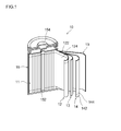
本実施形態に係るリチウムイオン電池の概略構成を図1に示す。このリチウムイオン電池10は、正極12および負極14を具備する電極体11が、図示しない非水電解液とともに、該電極体を収容し得る形状の電池ケース15に収容された構成を有する。電池ケース15は、有底円筒状のケース本体152と、上記開口部を塞ぐ蓋体154とを備える。蓋体154およびケース本体152はいずれも金属製であって相互に絶縁されており、それぞれ正負極の集電体122,142と電気的に接続されている。すなわち、このリチウムイオン電池10では、蓋体154が正極端子、ケース本体152が負極端子を兼ねている。 <First embodiment>
FIG. 1 shows a schematic configuration of the lithium ion battery according to the present embodiment. The
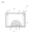
本実施形態に係るリチウムイオン電池の概略構成を図2,3に示す。このリチウムイオン電池20は、偏平な角型形状の容器21(典型的には金属製であり、樹脂製であってもよい。)を備える。この容器21の中に捲回電極体30が収容されている。本実施形態の電極体30は、第一実施形態と同様の材料を用いてなる正極シート32、負極シート34および二枚のセパレータ33を、両電極シート32,34の合材層非形成部がセパレータ33の長手方向に沿う一方の端部と他方の端部からそれぞれはみ出すように重ね合わせて捲回し、その捲回体を側面方向から押圧して拉げさせることにより、容器21の形状に合わせた扁平形状に形成されている。 <Second embodiment>
A schematic configuration of the lithium ion battery according to the present embodiment is shown in FIGS. The
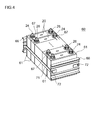
本実施形態に係る組電池の概略構成を図4に示す。この組電池60は、第二実施形態に係る電池20の複数個(典型的には10個以上、好ましくは10~30個程度、例えば20個)を用いて構築されている。これらの電池(単電池)20は、それぞれの正極端子24および負極端子26が交互に配置されるように一つづつ反転させつつ、容器21の幅広な面(すなわち、容器21内に収容される捲回電極体30の扁平面に対応する面)が対向する方向に配列されている。当該配列する単電池20間ならびに単電池配列方向(積層方向)の両アウトサイドには、所定形状の冷却板61が、容器21の幅広面に密接した状態で配置されている。この冷却板61は、使用時に各単電池内で発生する熱を効率よく放散させるための放熱部材として機能するものであって、単電池20間に冷却用流体(典型的には空気)を導入可能な形状(例えば、長方形状の冷却板61の一辺から垂直に延びて対向する辺に至る複数の平行な溝が表面に設けられた形状)を有する。熱伝導性の良い金属製もしくは軽量で硬質なポリプロピレンその他の合成樹脂製の冷却板61が好適である。 <Third embodiment>
FIG. 4 shows a schematic configuration of the assembled battery according to the present embodiment. This assembled
槽内温度40℃に設定された反応槽内にイオン交換水を入れ、攪拌しつつ窒素ガスを流通させて、該イオン交換水を窒素置換するとともに反応槽内を酸素ガス(O2)濃度2.0%の非酸化性雰囲気に調整した。次いで、25%水酸化ナトリウム水溶液と25%アンモニア水とを、液温25℃を基準として測定するpHが12.5となり且つ液中NH4 +濃度が5g/Lとなるように加えた。 <Manufacture of active material particles having a perforated hollow structure (
Ion exchange water is put into a reaction tank set at a temperature of 40 ° C., and nitrogen gas is circulated while stirring to replace the ion exchange water with nitrogen, and oxygen gas (O 2 ) concentration in the reaction tank is 2 Adjusted to 0.0% non-oxidizing atmosphere. Next, a 25% aqueous sodium hydroxide solution and 25% aqueous ammonia were added so that the pH measured on the basis of the liquid temperature of 25 ° C. was 12.5 and the NH 4 + concentration in the liquid was 5 g / L.
硝酸リチウム、硝酸ニッケル、硝酸コバルトおよび硝酸マンガンを、Li:Ni:Co;Mnのモル比が1.15:0.33:0.33:0.33となり且つこれら金属元素の合計モル濃度が1.5モル/Lとなるように水に溶解させて、混合水溶液を調整した。
この混合水溶液のミストを700℃の加熱炉中に導入して熱分解させることにより、Li1.15Ni0.33Co0.33Mn0.33O2で表わされる組成の複合酸化物粒子を得た(噴霧熱分解法)。この粒子を950℃で10時間加熱(アニール)して、表1に示す平均粒径、比表面積および平均硬度を有するサンプル13,14の活物質粒子を得た。なお、サンプル13と14とは、上記ミストの平均液滴径を互いに異ならせて製造したものである。 <Manufacture of active material particles (
Lithium nitrate, nickel nitrate, cobalt nitrate, and manganese nitrate have a Li: Ni: Co; Mn molar ratio of 1.15: 0.33: 0.33: 0.33, and the total molar concentration of these metal elements is 1. It was dissolved in water so as to be 5 mol / L to prepare a mixed aqueous solution.
The mixed aqueous solution mist was introduced into a 700 ° C. heating furnace and thermally decomposed to obtain composite oxide particles having a composition represented by Li 1.15 Ni 0.33 Co 0.33 Mn 0.33 O 2 (spray pyrolysis method). . The particles were heated (annealed) at 950 ° C. for 10 hours to obtain active material particles of
オーバーフローパイプを備え槽内温度40℃に設定された反応槽内に、イオン交換水を入れ、攪拌しつつ窒素ガスを流通させて、該イオン交換水を窒素置換するとともに反応槽内を酸素ガス(O2)濃度2.0%の非酸化性雰囲気に調整した。次いで、25%水酸化ナトリウム水溶液と25%アンモニア水とを、液温25℃を基準として測定するpHが12.0となり且つ液中NH4 +濃度が15g/Lとなるように加えた。
硫酸ニッケル、硫酸コバルトおよび硫酸マンガンを、Ni:Co:Mnのモル比が0.33:0.33:0.33となり且つこれら金属元素の合計モル濃度が1.8モル/Lとなるように水に溶解させて、混合水溶液を調整した。この混合水溶液と25%NaOH水溶液と25%アンモニア水とを上記反応槽内に、該反応槽内に析出するNiCoMn複合水酸化物粒子の平均的な滞留時間が10時間となる一定速度で供給し、且つ反応液をpH12.0、NH4 +濃度15g/Lになるように制御して連続的に晶析をさせ、反応槽内が定常状態になった後に、上記オーバーフローパイプよりNiCoMn複合水酸化物(生成物)を連続的に採取し、水洗して乾燥させた。このようにして、Ni0.33Co0.33Mn0.33(OH)2+α(ここで、式中のαは0≦α≦0.5である。)で表わされる組成の複合水酸化物粒子を得た。 <Production of solid active material particles (
Ion exchange water is placed in a reaction vessel equipped with an overflow pipe and set to a temperature of 40 ° C., and nitrogen gas is circulated while stirring to replace the ion exchange water with nitrogen and oxygen gas ( O 2 ) was adjusted to a non-oxidizing atmosphere having a concentration of 2.0%. Next, a 25% aqueous sodium hydroxide solution and 25% aqueous ammonia were added so that the pH measured on the basis of the liquid temperature of 25 ° C. was 12.0 and the NH 4 + concentration in the liquid was 15 g / L.
In nickel sulfate, cobalt sulfate, and manganese sulfate, the molar ratio of Ni: Co: Mn is 0.33: 0.33: 0.33, and the total molar concentration of these metal elements is 1.8 mol / L. A mixed aqueous solution was prepared by dissolving in water. This mixed aqueous solution, 25% NaOH aqueous solution, and 25% aqueous ammonia are supplied into the reaction vessel at a constant rate at which the average residence time of NiCoMn composite hydroxide particles precipitated in the reaction vessel is 10 hours. In addition, the reaction solution was controlled to have a pH of 12.0 and an NH 4 + concentration of 15 g / L, and was continuously crystallized. After the inside of the reaction vessel reached a steady state, NiCoMn composite hydroxide was obtained from the overflow pipe. A product (product) was continuously collected, washed with water and dried. In this manner, composite hydroxide particles having a composition represented by Ni 0.33 Co 0.33 Mn 0.33 (OH) 2 + α (where α is 0 ≦ α ≦ 0.5) were obtained. .
上記で得られた活物質粒子サンプルと、導電材としてのアセチレンブラックと、PVDFとを、これら材料の質量比が85:10:5となり且つ固形分濃度(NV)が約50質量%となるようにNMPと混合して、各活物質粒子サンプルに対応する正極合材組成物を調製した。 <Preparation of positive electrode sheet>
The active material particle sample obtained above, acetylene black as a conductive material, and PVDF are such that the mass ratio of these materials is 85: 10: 5 and the solid content concentration (NV) is about 50 mass%. A positive electrode mixture composition corresponding to each active material particle sample was prepared by mixing with NMP.

天然黒鉛粒子とSBRとCMCとを、これら材料の質量比が98:1:1であり且つNVが45質量%となるようにイオン交換水と混合して、水系の活物質組成物(負極合材組成物)を調製した。この組成物を厚さ約10μmの長尺状銅箔(負極集電体)の両面に塗布して乾燥させ、ロールプレスを行った。このようにして、集電体の両面に負極合材層を有するシート状負極(負極シート)を作製した。該負極シートの全体の厚みは約50μmであった。 <Production of lithium ion battery>
Natural graphite particles, SBR, and CMC are mixed with ion-exchanged water so that the mass ratio of these materials is 98: 1: 1 and NV is 45% by mass to obtain an aqueous active material composition (negative electrode composite). A material composition) was prepared. This composition was applied to both sides of a long copper foil (negative electrode current collector) having a thickness of about 10 μm and dried, followed by roll pressing. Thus, the sheet-like negative electrode (negative electrode sheet) which has a negative mix layer on both surfaces of a collector was produced. The total thickness of the negative electrode sheet was about 50 μm.
上記で作製した各電池をSOC(State of Charge)60%に調整し、25℃の温度下にて20Cの定電流で放電させ、その電圧降下から初期IV抵抗を求めた。 <Resistance increase rate due to high rate cycle>
Each of the batteries prepared above was adjusted to SOC (State of Charge) 60%, discharged at a constant current of 20 C at a temperature of 25 ° C., and the initial IV resistance was determined from the voltage drop.
(I).20C(ここでは6A)の定電流で10秒間放電させる。
(II).5秒間休止する。
(III).5Cの定電流で40秒間充電する。
(IV).5秒間休止する。 Next, each battery was adjusted to
(I) Discharge for 10 seconds at a constant current of 20 C (6 A in this case).
(II). Pause for 5 seconds.
(III) Charge for 40 seconds at a constant current of 5C.
(IV) Pause for 5 seconds.
上記で作製した各電池につき、測定温度-30℃において、測定周波数範囲0.001~10000Hz、振幅5mVの条件で交流インピーダンス測定を行い、Cole-Coleプロットの等価回路フィッティングにより直流抵抗Rsolおよび反応抵抗Rct(初期反応抵抗)を求めた。 <Low temperature initial reaction resistance>
For each of the batteries prepared above, AC impedance measurement was performed at a measurement temperature of −30 ° C. under the conditions of a measurement frequency range of 0.001 to 10000 Hz and an amplitude of 5 mV, and DC resistance Rsol and reaction resistance were obtained by equivalent circuit fitting of the Cole-Cole plot. Rct (initial reaction resistance) was determined.
上記低温初期反応抵抗測定後の電池に対し、60℃において、SOC0%~100%(上限電圧4.1V、下限電圧3.0V)の範囲で4C(1.2A)の定電流充電と4Cの定電流放電とを500回繰り返す耐久サイクル試験を行った。上記耐久サイクル試験後の各電池につき、低温初期反応抵抗の測定と同様にして、耐久サイクル後の低温反応抵抗を測定した。そして、耐久サイクル後の反応抵抗値を初期の反応抵抗値で除すことにより、上記耐久サイクル試験による抵抗上昇率(倍)を算出した。 <Durability evaluation>
With respect to the battery after the above low temperature initial reaction resistance measurement, 4C (1.2 A) constant current charging and 4 C of SOC in the range of SOC 0% to 100% (upper limit voltage 4.1 V, lower limit voltage 3.0 V) at 60 ° C. The endurance cycle test was repeated 500 times with constant current discharge. For each battery after the endurance cycle test, the low temperature reaction resistance after the endurance cycle was measured in the same manner as the measurement of the low temperature initial reaction resistance. And the resistance increase rate (times) by the said endurance cycle test was computed by dividing the reaction resistance value after an endurance cycle by the initial reaction resistance value.
以上の結果を表2に示す。 Moreover, each battery produced above was charged at a constant current of 1 C up to 4.1 V under a temperature condition of 25 ° C., and then charged at a constant voltage until the total charging time was 2 hours. The battery after such CC-CV charging is held at 25 ° C. for 24 hours, and then discharged at 25 ° C. with a constant current of 1 C from 4.1 V to 3.0 V, and then until the total discharge time reaches 2 hours. The battery was discharged with voltage, and the discharge capacity (initial capacity) at this time was measured. The battery after the initial capacity measurement was subjected to the above durability cycle test. The battery after the endurance cycle was discharged at a constant current of 1 C from 4.1 V to 3.0 V at 25 ° C., and then discharged at a constant voltage until the total discharge time was 2 hours. (Capacity after cycle) was measured. And the capacity | capacitance maintenance factor (%) in the said 500 charging / discharging cycle was calculated | required by following Formula: {(capacity after cycling) / (initial capacity)} * 100;
The results are shown in Table 2.

10 リチウムイオン電池
11 電極体
12 正極(正極シート)
13 セパレータ
14 負極(負極シート)
122 正極集電体
124 正極合材層
142 負極集電体
144 負極合材層
20 リチウムイオン電池(単電池)
24 正極端子
26 負極端子
30 電極体
32 正極シート
33 セパレータ
34 負極シート
60 組電池
61 冷却板
67 接続具
68,69 エンドプレート
71 拘束バンド 1 Automobile (vehicle)
10
13
122 positive electrode
24
Claims (13)
- リチウム二次電池用の活物質粒子であって、
リチウム遷移金属酸化物の一次粒子が複数集合した二次粒子と、その内側に形成された中空部とを有する中空構造を構成しており、
前記二次粒子には、外部から前記中空部まで貫通する貫通孔が形成されており、
BET比表面積が0.5~1.9m2/gである、活物質粒子。 Active material particles for a lithium secondary battery,
A hollow structure having a secondary particle in which a plurality of primary particles of a lithium transition metal oxide are aggregated and a hollow portion formed inside the secondary particle,
In the secondary particles, a through-hole penetrating from the outside to the hollow portion is formed,
Active material particles having a BET specific surface area of 0.5 to 1.9 m 2 / g. - 前記貫通孔の開口幅が平均0.01μm以上である、請求項1に記載の活物質粒子。 The active material particles according to claim 1, wherein an average opening width of the through holes is 0.01 μm or more.
- 直径50μmの平面ダイヤモンド圧子を使用して負荷速度0.5mN/秒~3mN/秒の条件で行われるダイナミック硬度測定において、平均硬度が0.5MPa以上である、請求項1または2に記載の活物質粒子。 3. The active hardness according to claim 1, wherein the average hardness is 0.5 MPa or more in dynamic hardness measurement performed using a flat diamond indenter having a diameter of 50 μm under a load speed of 0.5 mN / second to 3 mN / second. Substance particles.
- 前記貫通孔の数は、前記活物質粒子の一粒子当たり平均1~20個である、請求項1から3のいずれか一項に記載の活物質粒子。 4. The active material particles according to claim 1, wherein the number of the through holes is 1 to 20 on average per one particle of the active material particles.
- 平均粒径が3μm~10μmである、請求項1から4のいずれか一項に記載の活物質粒子。 The active material particles according to any one of claims 1 to 4, wherein the average particle diameter is 3 μm to 10 μm.
- 前記リチウム遷移金属酸化物は、ニッケルを構成元素として含む層状構造の化合物である、請求項1から5のいずれか一項に記載の活物質粒子。 The active material particles according to any one of claims 1 to 5, wherein the lithium transition metal oxide is a compound having a layered structure containing nickel as a constituent element.
- 前記リチウム遷移金属酸化物は、ニッケル、コバルトおよびマンガンを構成元素として含む層状構造の化合物である、請求項1から6のいずれか一項に記載の活物質粒子。 The active material particles according to any one of claims 1 to 6, wherein the lithium transition metal oxide is a compound having a layered structure containing nickel, cobalt, and manganese as constituent elements.
- 正極と負極と非水電解液とを備えるリチウム二次電池であって、
前記正極および負極のうち少なくとも一方は、請求項1から7のいずれか一項に記載の活物質粒子を有する中空活物質含有電極である、リチウム二次電池。 A lithium secondary battery comprising a positive electrode, a negative electrode, and a non-aqueous electrolyte,
At least one is a lithium secondary battery which is a hollow active material containing electrode which has the active material particle as described in any one of Claim 1 to 7 among the said positive electrode and a negative electrode. - 車両の駆動電源として用いられる、請求項8に記載のリチウム二次電池。 The lithium secondary battery according to claim 8, which is used as a driving power source for a vehicle.
- 請求項8または9に記載の電池を備える、車両。 A vehicle comprising the battery according to claim 8 or 9.
- リチウム遷移金属酸化物の一次粒子が複数集合した二次粒子と、その内側に形成された中空部とを有し、前記二次粒子には外部から前記中空部まで貫通する貫通孔が形成されている孔開き中空構造の活物質粒子を製造する方法であって:
遷移金属化合物の水性溶液にアンモニウムイオンを供給して、前記遷移金属水酸化物の粒子を前記水性溶液から析出させる原料水酸化物生成工程、ここで、前記水性溶液は、前記リチウム遷移金属酸化物を構成する遷移金属元素の少なくとも一つを含む;
前記遷移金属水酸化物とリチウム化合物とを混合して未焼成の混合物を調製する混合工程;および、
前記混合物を焼成して前記活物質粒子を得る焼成工程;
を包含し、
ここで、前記原料水酸化物生成工程は、pH12以上かつアンモニウムイオン濃度25g/L以下で前記水性溶液から前記遷移金属水酸化物を析出させる核生成段階と、その析出した遷移金属水酸化物をpH12未満かつアンモニウムイオン濃度3g/L以上で成長させる粒子成長段階とを含む、活物質粒子製造方法。 A secondary particle in which a plurality of primary particles of a lithium transition metal oxide are aggregated, and a hollow portion formed inside the secondary particle, and a through-hole penetrating from the outside to the hollow portion is formed in the secondary particle. A method for producing perforated hollow structure active material particles comprising:
A raw material hydroxide generating step of supplying ammonium ions to an aqueous solution of a transition metal compound to precipitate particles of the transition metal hydroxide from the aqueous solution, wherein the aqueous solution is the lithium transition metal oxide Including at least one of transition metal elements constituting
A mixing step of mixing the transition metal hydroxide and the lithium compound to prepare an unfired mixture; and
A firing step of firing the mixture to obtain the active material particles;
Including
Here, the raw material hydroxide generation step includes a nucleation stage in which the transition metal hydroxide is precipitated from the aqueous solution at a pH of 12 or more and an ammonium ion concentration of 25 g / L or less, and the precipitated transition metal hydroxide is a particle growth step of growing at a pH of less than 12 and an ammonium ion concentration of 3 g / L or more. - 前記焼成工程は、最高焼成温度が800℃~1100℃となるように行われる、請求項11に記載の方法。 The method according to claim 11, wherein the firing step is performed such that a maximum firing temperature is 800 ° C to 1100 ° C.
- 前記焼成工程は、前記混合物を700℃以上900℃以下の温度T1で焼成する第一焼成段階と、その第一焼成段階を経た結果物を800℃以上1100℃以下であって且つ前記第一焼成段階における焼成温度T1よりも高い温度T2で焼成する第二焼成段階とを含む、請求項11または12に記載の方法。 The firing step includes a first firing step of firing the mixture at a temperature T1 of 700 ° C. or more and 900 ° C. or less, and a result obtained through the first firing step of 800 ° C. or more and 1100 ° C. or less and the first firing step. The method according to claim 11 or 12, comprising a second firing step of firing at a temperature T2 higher than the firing temperature T1 in the step.
Priority Applications (7)
| Application Number | Priority Date | Filing Date | Title |
|---|---|---|---|
| KR1020157020743A KR101668974B1 (en) | 2009-12-02 | 2010-10-07 | Active material particles and use of same |
| US13/513,209 US20120282525A1 (en) | 2009-12-02 | 2010-10-07 | Active material particles and use of same |
| CN201080051688.6A CN102612772B (en) | 2009-12-02 | 2010-10-07 | Active material particles and use of same |
| CA2781658A CA2781658C (en) | 2009-12-02 | 2010-10-07 | Active material particles having secondary particles with lithium transition metal oxides and method for procucing the same |
| EP10834435.9A EP2509142B1 (en) | 2009-12-02 | 2010-10-07 | Active material particles and use of same |
| US13/618,526 US8486564B2 (en) | 2009-12-02 | 2012-09-14 | Method of producing active material particles with lithium transition metal oxide secondary particles |
| US13/941,253 US9391318B2 (en) | 2009-12-02 | 2013-07-12 | Active material particles for a lithium secondary battery |
Applications Claiming Priority (2)
| Application Number | Priority Date | Filing Date | Title |
|---|---|---|---|
| JP2009274381A JP5175826B2 (en) | 2009-12-02 | 2009-12-02 | Active material particles and use thereof |
| JP2009-274381 | 2009-12-02 |
Related Child Applications (3)
| Application Number | Title | Priority Date | Filing Date |
|---|---|---|---|
| US13/513,209 A-371-Of-International US20120282525A1 (en) | 2009-12-02 | 2010-10-07 | Active material particles and use of same |
| US13/618,526 Division US8486564B2 (en) | 2009-12-02 | 2012-09-14 | Method of producing active material particles with lithium transition metal oxide secondary particles |
| US13/941,253 Continuation US9391318B2 (en) | 2009-12-02 | 2013-07-12 | Active material particles for a lithium secondary battery |
Publications (1)
| Publication Number | Publication Date |
|---|---|
| WO2011067982A1 true WO2011067982A1 (en) | 2011-06-09 |
Family
ID=44114841
Family Applications (1)
| Application Number | Title | Priority Date | Filing Date |
|---|---|---|---|
| PCT/JP2010/067691 WO2011067982A1 (en) | 2009-12-02 | 2010-10-07 | Active material particles and use of same |
Country Status (7)
| Country | Link |
|---|---|
| US (3) | US20120282525A1 (en) |
| EP (2) | EP2509142B1 (en) |
| JP (1) | JP5175826B2 (en) |
| KR (2) | KR101668974B1 (en) |
| CN (1) | CN102612772B (en) |
| CA (1) | CA2781658C (en) |
| WO (1) | WO2011067982A1 (en) |
Cited By (13)
| Publication number | Priority date | Publication date | Assignee | Title |
|---|---|---|---|---|
| US20120145564A1 (en) * | 2010-12-09 | 2012-06-14 | Yokogawa Electric Corporation | Fuel cell evaluator and fuel cell evaluation method |
| JP2013045761A (en) * | 2011-08-26 | 2013-03-04 | Toyota Motor Corp | Lithium secondary battery |
| WO2013031478A1 (en) * | 2011-08-31 | 2013-03-07 | トヨタ自動車株式会社 | Lithium rechargeable battery |
| WO2013094701A1 (en) * | 2011-12-20 | 2013-06-27 | 住友金属鉱山株式会社 | Nickel compound hydroxide and method for producing same, positive pole active substance for nonaqueous electrolyte secondary cell and method for producing same, and nonaqueous electrolyte secondary cell |
| WO2014060814A1 (en) | 2012-10-17 | 2014-04-24 | Toyota Jidosha Kabushiki Kaisha | Secondary battery |
| US20140199589A1 (en) * | 2013-01-11 | 2014-07-17 | Gs Yuasa International Ltd. | Electric storage device and manufacturing method thereof |
| WO2014181891A1 (en) * | 2013-05-10 | 2014-11-13 | 住友金属鉱山株式会社 | Transition metal composite hydroxide particles, method for producing same, positive electrode active material for non-aqueous electrolyte secondary battery, method for producing same, and non-aqueous electrolyte secondary battery |
| WO2014203814A1 (en) * | 2013-06-17 | 2014-12-24 | 住友金属鉱山株式会社 | Nickel-cobalt-manganese composite hydroxide, and production method therefor |
| CN104396065A (en) * | 2012-06-29 | 2015-03-04 | 丰田自动车株式会社 | Lithium secondary battery and vehicle with the same |
| JP2015043332A (en) * | 2014-10-14 | 2015-03-05 | トヨタ自動車株式会社 | Lithium secondary battery |
| JP2016129114A (en) * | 2015-01-09 | 2016-07-14 | トヨタ自動車株式会社 | Nonaqueous electrolyte secondary battery electrode and method for manufacturing the same |
| US10109849B2 (en) | 2012-06-06 | 2018-10-23 | Sumitomo Metal Mining Co., Ltd. | Nickel composite hydroxide, cathode active material for non-aqueous electrolyte secondary battery, and methods for producing these |
| JP7422121B2 (en) | 2021-12-27 | 2024-01-25 | プライムアースEvエナジー株式会社 | Lithium ion secondary battery |
Families Citing this family (71)
| Publication number | Priority date | Publication date | Assignee | Title |
|---|---|---|---|---|
| JP5464348B2 (en) * | 2010-02-26 | 2014-04-09 | 住友金属鉱山株式会社 | Nickel-cobalt composite hydroxide for non-aqueous electrolyte secondary battery positive electrode active material and method for producing the same, and method for producing non-aqueous electrolyte secondary battery positive electrode active material using the nickel-cobalt composite hydroxide |
| WO2012049779A1 (en) * | 2010-10-15 | 2012-04-19 | トヨタ自動車株式会社 | Secondary battery |
| KR101510026B1 (en) | 2010-10-15 | 2015-04-07 | 도요타지도샤가부시키가이샤 | Secondary battery |
| CA2817494C (en) | 2010-11-12 | 2016-01-12 | Toyota Jidosha Kabushiki Kaisha | Secondary battery |
| US9184442B2 (en) | 2010-11-12 | 2015-11-10 | Toyota Jidosha Kabushiki Kaisha | Secondary battery |
| JP5626614B2 (en) * | 2011-03-03 | 2014-11-19 | トヨタ自動車株式会社 | Non-aqueous electrolyte secondary battery |
| JP5551195B2 (en) * | 2011-03-16 | 2014-07-16 | 日本化学工業株式会社 | Method for producing lithium nickel manganese cobalt composite oxide |
| US8945768B2 (en) | 2011-05-06 | 2015-02-03 | Toyota Jidosha Kabushiki Kaisha | Lithium-ion secondary battery |
| WO2012164752A1 (en) * | 2011-05-30 | 2012-12-06 | 住友金属鉱山株式会社 | Positive electrode active material for nonaqueous secondary batteries, method for producing same, and nonaqueous electrolyte secondary battery using positive electrode active material |
| WO2012164693A1 (en) * | 2011-05-31 | 2012-12-06 | トヨタ自動車株式会社 | Lithium secondary battery |
| GB2492167C (en) | 2011-06-24 | 2018-12-05 | Nexeon Ltd | Structured particles |
| JP5651547B2 (en) | 2011-06-29 | 2015-01-14 | 日立オートモティブシステムズ株式会社 | Lithium ion secondary battery |
| JP5725358B2 (en) * | 2011-09-15 | 2015-05-27 | トヨタ自動車株式会社 | Lithium secondary battery |
| JP5920872B2 (en) * | 2011-11-25 | 2016-05-18 | 株式会社田中化学研究所 | Lithium metal composite oxide and method for producing the same |
| JP5858279B2 (en) * | 2011-12-05 | 2016-02-10 | トヨタ自動車株式会社 | Lithium ion secondary battery |
| JP5709010B2 (en) * | 2011-12-20 | 2015-04-30 | トヨタ自動車株式会社 | Non-aqueous electrolyte secondary battery |
| JP5641362B2 (en) * | 2011-12-26 | 2014-12-17 | トヨタ自動車株式会社 | Method for producing positive electrode active material |
| JP5682796B2 (en) * | 2012-01-12 | 2015-03-11 | トヨタ自動車株式会社 | Lithium secondary battery |
| KR20140133529A (en) | 2012-01-30 | 2014-11-19 | 넥세온 엘티디 | Composition of si/c electro active material |
| GB2499984B (en) | 2012-02-28 | 2014-08-06 | Nexeon Ltd | Composite particles comprising a removable filler |
| KR101361118B1 (en) * | 2012-03-08 | 2014-02-13 | 주식회사 라미나 | Gas-liquid reactor using lithium secondary battery cathode active material, method of manufacture |
| DE112012006167B4 (en) | 2012-03-30 | 2024-03-28 | Toyota Jidosha Kabushiki Kaisha | Lithium-ion secondary battery |
| JP6055967B2 (en) * | 2012-05-10 | 2017-01-11 | 株式会社田中化学研究所 | Positive electrode active material and method for producing the same, positive electrode active material precursor, positive electrode for lithium secondary battery, and lithium secondary battery |
| GB2502625B (en) | 2012-06-06 | 2015-07-29 | Nexeon Ltd | Method of forming silicon |
| JP5664930B2 (en) | 2012-06-29 | 2015-02-04 | トヨタ自動車株式会社 | Nonaqueous electrolyte secondary battery |
| WO2014061399A1 (en) * | 2012-10-15 | 2014-04-24 | 日本碍子株式会社 | Positive active material for lithium secondary battery, and positive electrode obtained using same |
| GB2507535B (en) | 2012-11-02 | 2015-07-15 | Nexeon Ltd | Multilayer electrode |
| JP6341095B2 (en) * | 2012-11-13 | 2018-06-13 | 戸田工業株式会社 | Non-aqueous electrolyte secondary battery lithium manganate particle powder, method for producing the same, and non-aqueous electrolyte secondary battery |
| JP6369739B2 (en) | 2013-01-11 | 2018-08-08 | 株式会社Gsユアサ | Storage element and method for manufacturing the same |
| WO2014136760A1 (en) * | 2013-03-04 | 2014-09-12 | 三井金属鉱業株式会社 | Lithium metal composite oxide powder |
| US20160006029A1 (en) * | 2013-03-26 | 2016-01-07 | Sanyo Electric Co., Ltd. | Non-aqueous electrolyte secondary battery positive electrode active material and non-aqueous electrolyte secondary battery by using same |
| WO2014195995A1 (en) | 2013-06-05 | 2014-12-11 | トヨタ自動車株式会社 | Lithium-ion secondary battery |
| JP6044463B2 (en) * | 2013-06-19 | 2016-12-14 | 住友金属鉱山株式会社 | Nickel cobalt manganese composite hydroxide and method for producing the same |
| US10629903B2 (en) * | 2013-07-31 | 2020-04-21 | Iucf-Hyu (Industry-University Cooperation Foundation Hanyang University) | Method for preparing transition metal composite oxide, transition metal composite oxide prepared thereby, and lithium composite oxide prepared using same |
| GB2516895C (en) * | 2013-08-05 | 2019-05-15 | Nexeon Ltd | Structured particles |
| JP6467352B2 (en) * | 2014-01-20 | 2019-02-13 | 住友化学株式会社 | Positive electrode active material and method for producing the same |
| JP6167943B2 (en) * | 2014-03-07 | 2017-07-26 | トヨタ自動車株式会社 | Nonaqueous electrolyte secondary battery |
| KR101567203B1 (en) | 2014-04-09 | 2015-11-09 | (주)오렌지파워 | Negative electrode material for rechargeable battery and method of fabricating the same |
| KR101604352B1 (en) | 2014-04-22 | 2016-03-18 | (주)오렌지파워 | Negative electrode active material and rechargeable battery having the same |
| KR102172026B1 (en) * | 2014-05-20 | 2020-10-30 | 삼성에스디아이 주식회사 | Active material precursor and preparing method thereof |
| JP6421690B2 (en) | 2014-07-17 | 2018-11-14 | 株式会社デンソー | Temperature sensor |
| GB2533161C (en) | 2014-12-12 | 2019-07-24 | Nexeon Ltd | Electrodes for metal-ion batteries |
| JP6383326B2 (en) * | 2015-06-05 | 2018-08-29 | プライムアースEvエナジー株式会社 | Nonaqueous electrolyte secondary battery and positive electrode active material of nonaqueous electrolyte secondary battery |
| JP6354995B2 (en) | 2015-08-07 | 2018-07-11 | トヨタ自動車株式会社 | Non-aqueous electrolyte secondary battery positive electrode material and method for producing the same |
| JP6284040B2 (en) * | 2015-08-07 | 2018-02-28 | トヨタ自動車株式会社 | Positive electrode material for lithium secondary battery and method for producing the same |
| JP6549444B2 (en) * | 2015-08-07 | 2019-07-24 | トヨタ自動車株式会社 | Method of producing active material particles, active material powder material and lithium ion secondary battery |
| JP7013871B2 (en) | 2015-10-28 | 2022-02-01 | 住友金属鉱山株式会社 | Positive electrode active material for non-aqueous electrolyte secondary battery and its manufacturing method, positive electrode mixture paste for non-aqueous electrolyte secondary battery and non-aqueous electrolyte secondary battery |
| CN108370035A (en) * | 2015-12-18 | 2018-08-03 | 日本碍子株式会社 | Plate lithium composite xoide and its manufacturing method |
| KR102389075B1 (en) * | 2016-06-14 | 2022-04-22 | 스미토모 긴조쿠 고잔 가부시키가이샤 | Method for producing nickel-containing hydroxide |
| US11302919B2 (en) | 2016-07-20 | 2022-04-12 | Samsung Sdi Co., Ltd. | Nickel-based active material for lithium secondary battery, method of preparing the same, and lithium secondary battery including positive electrode including the nickel-based active material |
| US11569503B2 (en) | 2016-07-20 | 2023-01-31 | Samsung Sdi Co., Ltd. | Nickel-based active material for lithium secondary battery, method of preparing the same, and lithium secondary battery including positive electrode including the nickel-based active material |
| JP6337360B2 (en) | 2016-08-31 | 2018-06-06 | 住友化学株式会社 | Positive electrode active material for lithium secondary battery, positive electrode for lithium secondary battery, and lithium secondary battery |
| JP6500001B2 (en) | 2016-08-31 | 2019-04-10 | 住友化学株式会社 | Positive electrode active material for lithium secondary battery, positive electrode for lithium secondary battery, and lithium secondary battery |
| JP6756246B2 (en) | 2016-11-21 | 2020-09-16 | トヨタ自動車株式会社 | Manufacturing method of granulated aggregate, manufacturing method of electrode plate, and manufacturing method of battery |
| US11024839B2 (en) | 2016-11-22 | 2021-06-01 | Sumitomo Metal Mining Co., Ltd. | Transition metal-containing composite hydroxide and production method thereof, and production method of positive electrode active material for nonaqueous electrolyte secondary battery |
| JPWO2018097191A1 (en) * | 2016-11-22 | 2019-06-24 | 住友金属鉱山株式会社 | Positive electrode active material for non-aqueous electrolyte secondary battery and non-aqueous electrolyte secondary battery |
| WO2018101806A1 (en) | 2016-12-02 | 2018-06-07 | 삼성에스디아이주식회사 | Nickel active material precursor for lithium secondary battery, method for producing nickel active material precursor, nickel active material for lithium secondary battery produced by method, and lithium secondary battery having cathode containing nickel active material |
| US11309542B2 (en) | 2016-12-08 | 2022-04-19 | Samsung Sdi Co., Ltd. | Nickel-based active material for lithium secondary battery, preparing method thereof, and lithium secondary battery including positive electrode including the same |
| US11456458B2 (en) | 2016-12-08 | 2022-09-27 | Samsung Sdi Co., Ltd. | Nickel-based active material precursor for lithium secondary battery, preparing method thereof, nickel-based active material for lithium secondary battery formed thereof, and lithium secondary battery comprising positive electrode including the nickel-based active material |
| JP6949297B2 (en) * | 2016-12-13 | 2021-10-13 | 住友金属鉱山株式会社 | Transition metal-containing composite hydroxide and its manufacturing method, and positive electrode active material for non-aqueous electrolyte secondary batteries and its manufacturing method |
| JP7343265B2 (en) * | 2017-07-12 | 2023-09-12 | 住友金属鉱山株式会社 | Positive electrode active material precursor for non-aqueous electrolyte secondary batteries, positive electrode active material for non-aqueous electrolyte secondary batteries, method for producing positive electrode active material precursor for non-aqueous electrolyte secondary batteries, and positive electrode active for non-aqueous electrolyte secondary batteries Method of manufacturing substances |
| JP6583359B2 (en) * | 2017-07-27 | 2019-10-02 | 住友金属鉱山株式会社 | Nickel cobalt manganese composite hydroxide |
| JP6495997B1 (en) | 2017-11-20 | 2019-04-03 | 住友化学株式会社 | Positive electrode active material for lithium secondary battery, positive electrode for lithium secondary battery, and lithium secondary battery |
| JP6799551B2 (en) * | 2018-02-07 | 2020-12-16 | 住友化学株式会社 | Manufacturing method of positive electrode active material for lithium secondary battery |
| JP2019175721A (en) | 2018-03-29 | 2019-10-10 | 三洋電機株式会社 | Manufacturing method for positive electrode for non-aqueous electrolyte secondary battery and manufacturing method for non-aqueous electrolyte secondary battery |
| JP7028716B2 (en) * | 2018-05-29 | 2022-03-02 | トヨタ自動車株式会社 | Positive electrode material |
| CN112798630A (en) * | 2019-11-13 | 2021-05-14 | 天津国安盟固利新材料科技股份有限公司 | Sample preparation method for representing element distribution uniformity |
| CN110931772B (en) * | 2020-02-12 | 2020-06-19 | 湖南长远锂科股份有限公司 | Preparation method of high-power type positive electrode material for lithium ion battery |
| CN112599742B (en) * | 2020-12-14 | 2022-03-18 | 宁德新能源科技有限公司 | Electrochemical device and electronic device |
| JP2022140180A (en) * | 2021-03-10 | 2022-09-26 | 茂 佐野 | Positive electrode and storage battery |
| JP2023031637A (en) * | 2021-08-25 | 2023-03-09 | 住友金属鉱山株式会社 | Valuable metal recovery method |
Citations (12)
| Publication number | Priority date | Publication date | Assignee | Title |
|---|---|---|---|---|
| JPH08321300A (en) | 1995-03-17 | 1996-12-03 | Canon Inc | Secondary battery using lithium |
| JPH1074516A (en) | 1996-08-29 | 1998-03-17 | Murata Mfg Co Ltd | Lithium secondary battery |
| JPH1074517A (en) | 1996-08-29 | 1998-03-17 | Murata Mfg Co Ltd | Lithium secondary battery |
| JPH1083816A (en) | 1996-07-16 | 1998-03-31 | Murata Mfg Co Ltd | Lithium secondary battery |
| JPH10255804A (en) * | 1997-01-07 | 1998-09-25 | Murata Mfg Co Ltd | Lithium secondary battery |
| JP2000323123A (en) * | 1999-05-06 | 2000-11-24 | Dowa Mining Co Ltd | Positive electrode active material and positive electrode for non-aqueous secondary battery |
| JP2000340226A (en) * | 1999-05-26 | 2000-12-08 | Kawasaki Steel Corp | Lithium manganese composite oxide particle and manufacture thereof |
| JP2004253174A (en) * | 2003-02-18 | 2004-09-09 | Nichia Chem Ind Ltd | Positive pole active material for nonaqueous electrolytic secondary battery |
| JP2005123179A (en) * | 2003-09-26 | 2005-05-12 | Mitsubishi Chemicals Corp | Lithium compound oxide particle for lithium secondary battery positive electrode material, and lithium secondary battery positive electrode using the same, and the lithium secondary battery |
| JP2006089364A (en) * | 2004-08-24 | 2006-04-06 | Sumitomo Metal Mining Co Ltd | Nickel hydroxide particle containing aluminum and its manufacturing method |
| JP2008266136A (en) * | 2003-04-17 | 2008-11-06 | Agc Seimi Chemical Co Ltd | Lithium-nickel-cobalt-manganese-containing composite oxide, raw material for positive electrode active material for lithium secondary battery, and method for production thereof |
| JP2009259605A (en) * | 2008-04-17 | 2009-11-05 | Toyota Motor Corp | Positive electrode active substance, manufacturing method for same and battery provided with positive electrode active substance |
Family Cites Families (14)
| Publication number | Priority date | Publication date | Assignee | Title |
|---|---|---|---|---|
| DE69700735T2 (en) * | 1996-08-29 | 2000-03-02 | Murata Manufacturing Co | Lithium secondary battery |
| US6086843A (en) * | 1998-09-15 | 2000-07-11 | Ovonic Battery Company, Inc. | Structurally modified nickel hydroxide material and method for making same |
| US7585435B2 (en) * | 2000-11-06 | 2009-09-08 | Tanaka Chemical Corporation | High density cobalt-manganese coprecipitated nickel hydroxide and process for its production |
| EP1391950B1 (en) * | 2001-04-20 | 2010-08-25 | GS Yuasa Corporation | Anode active matter and production method therefor, non- aqueous electrolyte secondary battery-use anode, and non-aqueous electrolyte secondary battery |
| EP1667260A4 (en) * | 2003-09-26 | 2007-10-03 | Mitsubishi Chem Corp | Lithium composite oxide particle for lithium secondary battery positive electrode material and containing the same, positive electrode for lithium secondary battery and lithium secondary battery |
| US7709149B2 (en) | 2004-09-24 | 2010-05-04 | Lg Chem, Ltd. | Composite precursor for aluminum-containing lithium transition metal oxide and process for preparation of the same |
| JP4752244B2 (en) * | 2004-11-09 | 2011-08-17 | 三菱化学株式会社 | Layered lithium nickel manganese based composite oxide powder for lithium secondary battery positive electrode material, lithium secondary battery positive electrode using the same, and lithium secondary battery |
| US7682741B2 (en) | 2005-06-29 | 2010-03-23 | Panasonic Corporation | Composite particle for lithium rechargeable battery, manufacturing method of the same, and lithium rechargeable battery using the same |
| JP2007048692A (en) * | 2005-08-12 | 2007-02-22 | Hitachi Vehicle Energy Ltd | Lithium secondary battery cathode material, cathode plate for lithium secondary battery, and lithium secondary battery using this |
| JP2009032647A (en) * | 2007-06-25 | 2009-02-12 | Mitsubishi Chemicals Corp | Material for positive electrode active material for lithium secondary battery, positive electrode for lithium secondary battery using it, and lithium secondary battery |
| CN102769130A (en) | 2007-09-04 | 2012-11-07 | 三菱化学株式会社 | Lithium transition metal-type compound powder |
| JP2009099418A (en) * | 2007-10-17 | 2009-05-07 | Hitachi Vehicle Energy Ltd | Positive electrode material for lithium secondary battery, and lithium secondary battery using the same |
| US20090104517A1 (en) * | 2007-10-17 | 2009-04-23 | Toyotaka Yuasa | Cathode active material and lithium ion secondary battery containing the same |
| JP5225708B2 (en) * | 2008-02-27 | 2013-07-03 | 日本化学工業株式会社 | Lithium nickel manganese cobalt composite oxide for positive electrode active material of lithium secondary battery, method for producing the same, and lithium secondary battery |
-
2009
- 2009-12-02 JP JP2009274381A patent/JP5175826B2/en active Active
-
2010
- 2010-10-07 KR KR1020157020743A patent/KR101668974B1/en active IP Right Grant
- 2010-10-07 KR KR1020127017038A patent/KR101563775B1/en active IP Right Grant
- 2010-10-07 CA CA2781658A patent/CA2781658C/en active Active
- 2010-10-07 EP EP10834435.9A patent/EP2509142B1/en active Active
- 2010-10-07 US US13/513,209 patent/US20120282525A1/en not_active Abandoned
- 2010-10-07 CN CN201080051688.6A patent/CN102612772B/en active Active
- 2010-10-07 EP EP12181286.1A patent/EP2533329B1/en active Active
- 2010-10-07 WO PCT/JP2010/067691 patent/WO2011067982A1/en active Application Filing
-
2012
- 2012-09-14 US US13/618,526 patent/US8486564B2/en active Active
-
2013
- 2013-07-12 US US13/941,253 patent/US9391318B2/en active Active
Patent Citations (12)
| Publication number | Priority date | Publication date | Assignee | Title |
|---|---|---|---|---|
| JPH08321300A (en) | 1995-03-17 | 1996-12-03 | Canon Inc | Secondary battery using lithium |
| JPH1083816A (en) | 1996-07-16 | 1998-03-31 | Murata Mfg Co Ltd | Lithium secondary battery |
| JPH1074516A (en) | 1996-08-29 | 1998-03-17 | Murata Mfg Co Ltd | Lithium secondary battery |
| JPH1074517A (en) | 1996-08-29 | 1998-03-17 | Murata Mfg Co Ltd | Lithium secondary battery |
| JPH10255804A (en) * | 1997-01-07 | 1998-09-25 | Murata Mfg Co Ltd | Lithium secondary battery |
| JP2000323123A (en) * | 1999-05-06 | 2000-11-24 | Dowa Mining Co Ltd | Positive electrode active material and positive electrode for non-aqueous secondary battery |
| JP2000340226A (en) * | 1999-05-26 | 2000-12-08 | Kawasaki Steel Corp | Lithium manganese composite oxide particle and manufacture thereof |
| JP2004253174A (en) * | 2003-02-18 | 2004-09-09 | Nichia Chem Ind Ltd | Positive pole active material for nonaqueous electrolytic secondary battery |
| JP2008266136A (en) * | 2003-04-17 | 2008-11-06 | Agc Seimi Chemical Co Ltd | Lithium-nickel-cobalt-manganese-containing composite oxide, raw material for positive electrode active material for lithium secondary battery, and method for production thereof |
| JP2005123179A (en) * | 2003-09-26 | 2005-05-12 | Mitsubishi Chemicals Corp | Lithium compound oxide particle for lithium secondary battery positive electrode material, and lithium secondary battery positive electrode using the same, and the lithium secondary battery |
| JP2006089364A (en) * | 2004-08-24 | 2006-04-06 | Sumitomo Metal Mining Co Ltd | Nickel hydroxide particle containing aluminum and its manufacturing method |
| JP2009259605A (en) * | 2008-04-17 | 2009-11-05 | Toyota Motor Corp | Positive electrode active substance, manufacturing method for same and battery provided with positive electrode active substance |
Non-Patent Citations (1)
| Title |
|---|
| See also references of EP2509142A4 |
Cited By (35)
| Publication number | Priority date | Publication date | Assignee | Title |
|---|---|---|---|---|
| US9548506B2 (en) * | 2010-12-09 | 2017-01-17 | Yokogawa Electric Corporation | Fuel cell evaluator and fuel cell evaluation method |
| US20120145564A1 (en) * | 2010-12-09 | 2012-06-14 | Yokogawa Electric Corporation | Fuel cell evaluator and fuel cell evaluation method |
| KR20140052039A (en) * | 2011-08-26 | 2014-05-02 | 도요타지도샤가부시키가이샤 | Lithium rechargeable battery |
| JP2013045761A (en) * | 2011-08-26 | 2013-03-04 | Toyota Motor Corp | Lithium secondary battery |
| WO2013031477A1 (en) * | 2011-08-26 | 2013-03-07 | トヨタ自動車株式会社 | Lithium rechargeable battery |
| US9520592B2 (en) | 2011-08-26 | 2016-12-13 | Toyota Jidosha Kabushiki Kaisha | Lithium secondary battery |
| KR101649804B1 (en) * | 2011-08-26 | 2016-08-19 | 도요타지도샤가부시키가이샤 | Lithium rechargeable battery |
| EP2750223A4 (en) * | 2011-08-26 | 2015-04-22 | Toyota Motor Co Ltd | Lithium rechargeable battery |
| EP2750223A1 (en) * | 2011-08-26 | 2014-07-02 | Toyota Jidosha Kabushiki Kaisha | Lithium rechargeable battery |
| CN103765636A (en) * | 2011-08-26 | 2014-04-30 | 丰田自动车株式会社 | Lithium rechargeable battery |
| CN103765638A (en) * | 2011-08-31 | 2014-04-30 | 丰田自动车株式会社 | Lithium rechargeable battery |
| US20140205901A1 (en) * | 2011-08-31 | 2014-07-24 | Hiroki Nagai | Lithium rechargeable battery |
| US9653725B2 (en) | 2011-08-31 | 2017-05-16 | Toyota Jidosha Kabushiki Kaisha | Lithium rechargeable battery |
| WO2013031478A1 (en) * | 2011-08-31 | 2013-03-07 | トヨタ自動車株式会社 | Lithium rechargeable battery |
| JP2013051172A (en) * | 2011-08-31 | 2013-03-14 | Toyota Motor Corp | Lithium secondary battery |
| US9406930B2 (en) | 2011-12-20 | 2016-08-02 | Sumitomo Metal Mining Co., Ltd. | Nickel composite hydroxide and production method thereof, cathode active material for non-aqueous electrolyte secondary battery and production method thereof, and nonaqueous electrolyte secondary battery |
| KR20140126302A (en) * | 2011-12-20 | 2014-10-30 | 스미토모 긴조쿠 고잔 가부시키가이샤 | Nickel compound hydroxide and method for producing same, positive pole active substance for nonaqueous electrolyte secondary cell and method for producing same, and nonaqueous electrolyte secondary cell |
| JP2013147416A (en) * | 2011-12-20 | 2013-08-01 | Sumitomo Metal Mining Co Ltd | Nickel compound hydroxide and method for producing the same, positive pole active substance for nonaqueous electrolyte secondary cell and method for producing the same, and nonaqueous electrolyte secondary cell |
| WO2013094701A1 (en) * | 2011-12-20 | 2013-06-27 | 住友金属鉱山株式会社 | Nickel compound hydroxide and method for producing same, positive pole active substance for nonaqueous electrolyte secondary cell and method for producing same, and nonaqueous electrolyte secondary cell |
| KR101644252B1 (en) | 2011-12-20 | 2016-07-29 | 스미토모 긴조쿠 고잔 가부시키가이샤 | Nickel compound hydroxide and method for producing same, positive pole active substance for nonaqueous electrolyte secondary cell and method for producing same, and nonaqueous electrolyte secondary cell |
| US10109849B2 (en) | 2012-06-06 | 2018-10-23 | Sumitomo Metal Mining Co., Ltd. | Nickel composite hydroxide, cathode active material for non-aqueous electrolyte secondary battery, and methods for producing these |
| CN104396065A (en) * | 2012-06-29 | 2015-03-04 | 丰田自动车株式会社 | Lithium secondary battery and vehicle with the same |
| WO2014060814A1 (en) | 2012-10-17 | 2014-04-24 | Toyota Jidosha Kabushiki Kaisha | Secondary battery |
| US9954219B2 (en) * | 2013-01-11 | 2018-04-24 | Gs Yuasa International Ltd. | Electric storage device and manufacturing method thereof |
| US20140199589A1 (en) * | 2013-01-11 | 2014-07-17 | Gs Yuasa International Ltd. | Electric storage device and manufacturing method thereof |
| JP2016154143A (en) * | 2013-05-10 | 2016-08-25 | 住友金属鉱山株式会社 | Transition metal complex hydroxide particle and manufacturing method therefor, positive electrode active material for nonaqueous electrolyte secondary battery and manufacturing method therefor, and nonaqueous electrolyte secondary battery |
| WO2014181891A1 (en) * | 2013-05-10 | 2014-11-13 | 住友金属鉱山株式会社 | Transition metal composite hydroxide particles, method for producing same, positive electrode active material for non-aqueous electrolyte secondary battery, method for producing same, and non-aqueous electrolyte secondary battery |
| US10424787B2 (en) | 2013-05-10 | 2019-09-24 | Sumitomo Metal Mining Co., Ltd. | Transition metal composite hydroxide particles and production method thereof, cathode active material for non-aqueous electrolyte rechargeable battery and production method thereof, and nonaqueous electrolyte rechargeable battery |
| US11283072B2 (en) | 2013-05-10 | 2022-03-22 | Sumitomo Metal Mining Co., Ltd. | Transition metal composite hydroxide particles and production method thereof, cathode active material for non-aqueous electrolyte rechargeable battery and production method thereof, and nonaqueous electrolyte rechargeable battery |
| JP2015002120A (en) * | 2013-06-17 | 2015-01-05 | 住友金属鉱山株式会社 | Nickel cobalt manganese composite hydroxide, and method for manufacturing the same |
| WO2014203814A1 (en) * | 2013-06-17 | 2014-12-24 | 住友金属鉱山株式会社 | Nickel-cobalt-manganese composite hydroxide, and production method therefor |
| US10236504B2 (en) | 2013-06-17 | 2019-03-19 | Sumitomo Metal Mining Co., Ltd. | Nickel-cobalt-manganese composite hydroxide, and production method therefor |
| JP2015043332A (en) * | 2014-10-14 | 2015-03-05 | トヨタ自動車株式会社 | Lithium secondary battery |
| JP2016129114A (en) * | 2015-01-09 | 2016-07-14 | トヨタ自動車株式会社 | Nonaqueous electrolyte secondary battery electrode and method for manufacturing the same |
| JP7422121B2 (en) | 2021-12-27 | 2024-01-25 | プライムアースEvエナジー株式会社 | Lithium ion secondary battery |
Also Published As
| Publication number | Publication date |
|---|---|
| KR20120099108A (en) | 2012-09-06 |
| KR20150093252A (en) | 2015-08-17 |
| JP5175826B2 (en) | 2013-04-03 |
| CN102612772A (en) | 2012-07-25 |
| US8486564B2 (en) | 2013-07-16 |
| CA2781658C (en) | 2015-02-17 |
| JP2011119092A (en) | 2011-06-16 |
| EP2533329A2 (en) | 2012-12-12 |
| US20130302687A1 (en) | 2013-11-14 |
| US9391318B2 (en) | 2016-07-12 |
| EP2533329A3 (en) | 2013-03-06 |
| EP2509142B1 (en) | 2015-12-16 |
| KR101668974B1 (en) | 2016-10-24 |
| US20130011331A1 (en) | 2013-01-10 |
| CN102612772B (en) | 2015-05-06 |
| EP2533329B1 (en) | 2014-07-02 |
| EP2509142A1 (en) | 2012-10-10 |
| CA2781658A1 (en) | 2011-06-09 |
| KR101563775B1 (en) | 2015-10-27 |
| US20120282525A1 (en) | 2012-11-08 |
| EP2509142A4 (en) | 2013-09-18 |
Similar Documents
| Publication | Publication Date | Title |
|---|---|---|
| JP5175826B2 (en) | Active material particles and use thereof | |
| JP5858279B2 (en) | Lithium ion secondary battery | |
| JP6011838B2 (en) | Lithium secondary battery | |
| JP5299719B2 (en) | Lithium secondary battery | |
| JP5984026B2 (en) | Bimodal type negative electrode active material composition, and negative electrode active material, negative electrode active material composition, negative electrode, lithium secondary battery, battery module, and battery pack manufacturing method | |
| WO2012153379A1 (en) | Lithium ion secondary cell | |
| KR20100093034A (en) | Li-ni-based composite oxide particle powder for rechargeable battery with nonaqueous electrolyte, process for producing the powder, and rechargeable battery with nonaqueous electrolyte | |
| JP5696904B2 (en) | Lithium ion secondary battery and manufacturing method thereof | |
| US11967700B2 (en) | Non-aqueous electrolyte secondary battery including a positive electrode active substance containing a lithium composite oxide porous particle and a rock salt layer | |
| JP6493757B2 (en) | Lithium ion secondary battery | |
| JP2013206558A (en) | Active material and lithium ion secondary battery | |
| CN112242509B (en) | Nonaqueous electrolyte secondary battery | |
| JP7201539B2 (en) | Positive electrode material for lithium secondary battery, and lithium secondary battery using the same | |
| JP7152360B2 (en) | Positive electrode of secondary battery, and secondary battery using the same | |
| JP7104877B2 (en) | Cathode material for lithium secondary batteries | |
| JP7135040B2 (en) | Positive electrode active material, manufacturing method thereof, and lithium ion secondary battery | |
| WO2024090148A1 (en) | Non-aqueous electrolyte secondary battery | |
| JP6939045B2 (en) | Electrical device | |
| JP6549444B2 (en) | Method of producing active material particles, active material powder material and lithium ion secondary battery | |
| CN116195082A (en) | Nonaqueous electrolyte secondary battery |
Legal Events
| Date | Code | Title | Description |
|---|---|---|---|
| WWE | Wipo information: entry into national phase |
Ref document number: 201080051688.6 Country of ref document: CN |
|
| 121 | Ep: the epo has been informed by wipo that ep was designated in this application |
Ref document number: 10834435 Country of ref document: EP Kind code of ref document: A1 |
|
| ENP | Entry into the national phase |
Ref document number: 2781658 Country of ref document: CA |
|
| NENP | Non-entry into the national phase |
Ref country code: DE |
|
| WWE | Wipo information: entry into national phase |
Ref document number: 2010834435 Country of ref document: EP |
|
| ENP | Entry into the national phase |
Ref document number: 20127017038 Country of ref document: KR Kind code of ref document: A |
|
| WWE | Wipo information: entry into national phase |
Ref document number: 13513209 Country of ref document: US |
|
| NENP | Non-entry into the national phase |
Ref country code: JP |