WO2011065121A1 - Clip - Google Patents
Clip Download PDFInfo
- Publication number
- WO2011065121A1 WO2011065121A1 PCT/JP2010/066780 JP2010066780W WO2011065121A1 WO 2011065121 A1 WO2011065121 A1 WO 2011065121A1 JP 2010066780 W JP2010066780 W JP 2010066780W WO 2011065121 A1 WO2011065121 A1 WO 2011065121A1
- Authority
- WO
- WIPO (PCT)
- Prior art keywords
- clip
- insertion hole
- locking
- panel
- protrusion
- Prior art date
Links
- 238000003780 insertion Methods 0.000 claims abstract description 123
- 230000037431 insertion Effects 0.000 claims abstract description 123
- 239000000463 material Substances 0.000 claims abstract description 5
- 230000002093 peripheral effect Effects 0.000 claims description 7
- 230000007423 decrease Effects 0.000 claims description 3
- 239000011347 resin Substances 0.000 claims description 3
- 229920005989 resin Polymers 0.000 claims description 3
- 210000000078 claw Anatomy 0.000 abstract description 33
- 238000005452 bending Methods 0.000 abstract 1
- 230000005489 elastic deformation Effects 0.000 description 7
- 230000035515 penetration Effects 0.000 description 3
- 238000010586 diagram Methods 0.000 description 2
- 230000000452 restraining effect Effects 0.000 description 2
- 239000003381 stabilizer Substances 0.000 description 2
- 229930182556 Polyacetal Natural products 0.000 description 1
- 230000002411 adverse Effects 0.000 description 1
- 239000002184 metal Substances 0.000 description 1
- 239000007769 metal material Substances 0.000 description 1
- 238000000034 method Methods 0.000 description 1
- 230000000149 penetrating effect Effects 0.000 description 1
- 229920006324 polyoxymethylene Polymers 0.000 description 1
Images


Classifications
-
- F—MECHANICAL ENGINEERING; LIGHTING; HEATING; WEAPONS; BLASTING
- F16—ENGINEERING ELEMENTS AND UNITS; GENERAL MEASURES FOR PRODUCING AND MAINTAINING EFFECTIVE FUNCTIONING OF MACHINES OR INSTALLATIONS; THERMAL INSULATION IN GENERAL
- F16B—DEVICES FOR FASTENING OR SECURING CONSTRUCTIONAL ELEMENTS OR MACHINE PARTS TOGETHER, e.g. NAILS, BOLTS, CIRCLIPS, CLAMPS, CLIPS OR WEDGES; JOINTS OR JOINTING
- F16B21/00—Means for preventing relative axial movement of a pin, spigot, shaft or the like and a member surrounding it; Stud-and-socket releasable fastenings
- F16B21/10—Means for preventing relative axial movement of a pin, spigot, shaft or the like and a member surrounding it; Stud-and-socket releasable fastenings by separate parts
- F16B21/12—Means for preventing relative axial movement of a pin, spigot, shaft or the like and a member surrounding it; Stud-and-socket releasable fastenings by separate parts with locking-pins or split-pins thrust into holes
- F16B21/125—Means for preventing relative axial movement of a pin, spigot, shaft or the like and a member surrounding it; Stud-and-socket releasable fastenings by separate parts with locking-pins or split-pins thrust into holes radially resilient or with a snap-action member, e.g. elastic tooth, pawl with spring, resilient coil or wire
-
- B—PERFORMING OPERATIONS; TRANSPORTING
- B60—VEHICLES IN GENERAL
- B60R—VEHICLES, VEHICLE FITTINGS, OR VEHICLE PARTS, NOT OTHERWISE PROVIDED FOR
- B60R11/00—Arrangements for holding or mounting articles, not otherwise provided for
- B60R11/02—Arrangements for holding or mounting articles, not otherwise provided for for radio sets, television sets, telephones, or the like; Arrangement of controls thereof
- B60R11/0217—Arrangements for holding or mounting articles, not otherwise provided for for radio sets, television sets, telephones, or the like; Arrangement of controls thereof for loud-speakers
-
- F—MECHANICAL ENGINEERING; LIGHTING; HEATING; WEAPONS; BLASTING
- F16—ENGINEERING ELEMENTS AND UNITS; GENERAL MEASURES FOR PRODUCING AND MAINTAINING EFFECTIVE FUNCTIONING OF MACHINES OR INSTALLATIONS; THERMAL INSULATION IN GENERAL
- F16B—DEVICES FOR FASTENING OR SECURING CONSTRUCTIONAL ELEMENTS OR MACHINE PARTS TOGETHER, e.g. NAILS, BOLTS, CIRCLIPS, CLAMPS, CLIPS OR WEDGES; JOINTS OR JOINTING
- F16B5/00—Joining sheets or plates, e.g. panels, to one another or to strips or bars parallel to them
- F16B5/06—Joining sheets or plates, e.g. panels, to one another or to strips or bars parallel to them by means of clamps or clips
- F16B5/0607—Joining sheets or plates, e.g. panels, to one another or to strips or bars parallel to them by means of clamps or clips joining sheets or plates to each other
- F16B5/0621—Joining sheets or plates, e.g. panels, to one another or to strips or bars parallel to them by means of clamps or clips joining sheets or plates to each other in parallel relationship
- F16B5/0657—Joining sheets or plates, e.g. panels, to one another or to strips or bars parallel to them by means of clamps or clips joining sheets or plates to each other in parallel relationship at least one of the plates providing a raised structure, e.g. of the doghouse type, for connection with the clamps or clips of the other plate
-
- F—MECHANICAL ENGINEERING; LIGHTING; HEATING; WEAPONS; BLASTING
- F16—ENGINEERING ELEMENTS AND UNITS; GENERAL MEASURES FOR PRODUCING AND MAINTAINING EFFECTIVE FUNCTIONING OF MACHINES OR INSTALLATIONS; THERMAL INSULATION IN GENERAL
- F16B—DEVICES FOR FASTENING OR SECURING CONSTRUCTIONAL ELEMENTS OR MACHINE PARTS TOGETHER, e.g. NAILS, BOLTS, CIRCLIPS, CLAMPS, CLIPS OR WEDGES; JOINTS OR JOINTING
- F16B5/00—Joining sheets or plates, e.g. panels, to one another or to strips or bars parallel to them
- F16B5/06—Joining sheets or plates, e.g. panels, to one another or to strips or bars parallel to them by means of clamps or clips
- F16B5/0607—Joining sheets or plates, e.g. panels, to one another or to strips or bars parallel to them by means of clamps or clips joining sheets or plates to each other
- F16B5/0621—Joining sheets or plates, e.g. panels, to one another or to strips or bars parallel to them by means of clamps or clips joining sheets or plates to each other in parallel relationship
- F16B5/0642—Joining sheets or plates, e.g. panels, to one another or to strips or bars parallel to them by means of clamps or clips joining sheets or plates to each other in parallel relationship the plates being arranged one on top of the other and in full close contact with each other
-
- Y—GENERAL TAGGING OF NEW TECHNOLOGICAL DEVELOPMENTS; GENERAL TAGGING OF CROSS-SECTIONAL TECHNOLOGIES SPANNING OVER SEVERAL SECTIONS OF THE IPC; TECHNICAL SUBJECTS COVERED BY FORMER USPC CROSS-REFERENCE ART COLLECTIONS [XRACs] AND DIGESTS
- Y10—TECHNICAL SUBJECTS COVERED BY FORMER USPC
- Y10T—TECHNICAL SUBJECTS COVERED BY FORMER US CLASSIFICATION
- Y10T24/00—Buckles, buttons, clasps, etc.
- Y10T24/42—Independent, headed, aperture pass-through fastener
Landscapes
- Engineering & Computer Science (AREA)
- General Engineering & Computer Science (AREA)
- Mechanical Engineering (AREA)
- Connection Of Plates (AREA)
- Clamps And Clips (AREA)
- Fittings On The Vehicle Exterior For Carrying Loads, And Devices For Holding Or Mounting Articles (AREA)
- Snaps, Bayonet Connections, Set Pins, And Snap Rings (AREA)
- Insertion Pins And Rivets (AREA)
Abstract
Description
樹脂材よりなり、少なくとも2つの部材を締結するためのクリップであって、
前記2つの部材の少なくとも一方に設けられたクリップ挿通穴に押し込むために作業者によって操作される操作部と、前記クリップ挿通穴に押し込まれた状態で該クリップ挿通穴と係止する係止部と、を備え、
前記操作部と前記係止部との接続部分に前記クリップ挿通穴を内側から押圧する第1押圧部が設けられ、
前記係止部には、基端部を除く部分が係止部から分離され、その基端部を支点として弾性変形可能で、前記係止部から突出した部分が前記クリップ挿通穴を内側から押圧する第2押圧部が設けられ、
前記係止部が前記部材のクリップ挿通穴に挿通されたとき、前記操作部の底面部と前記係止部の底面部とが前記部材に当接した状態で、前記第1押圧部が前記クリップ挿通穴の第1開口縁部と密着し、前記第2押圧部が前記クリップ挿通穴の第2開口縁部と密着することを特徴としている。 The present invention for solving the above problems is as follows.
A clip made of a resin material for fastening at least two members,
An operation unit operated by an operator to be pushed into a clip insertion hole provided in at least one of the two members, and a latching portion that is engaged with the clip insertion hole while being pushed into the clip insertion hole. With
A first pressing portion that presses the clip insertion hole from the inside is provided at a connection portion between the operation portion and the locking portion,
The locking portion is separated from the locking portion except for the base end portion, and can be elastically deformed with the base end portion as a fulcrum, and the portion protruding from the locking portion presses the clip insertion hole from the inside. A second pressing part is provided,
When the locking portion is inserted into the clip insertion hole of the member, the first pressing portion is the clip while the bottom surface portion of the operation portion and the bottom surface portion of the locking portion are in contact with the member. The first opening edge portion of the insertion hole is in close contact, and the second pressing portion is in close contact with the second opening edge portion of the clip insertion hole.
前記第1押圧部が前記クリップ挿通穴の第1開口縁部と密着したとき、前記第2テーパ形状部が前記クリップ挿通穴の第2開口縁部と密着する。 Specifically, the second pressing portion has a triangular cross section, and a first taper shape in which a protruding length from the locking portion continuously increases from the distal end portion of the locking portion toward the operation portion. And a second taper-shaped portion that is connected to the first taper-shaped portion via the top of the second pressing portion, and the protrusion length from the locking portion continuously decreases toward the operation portion. Prepared,
When the first pressing portion is in close contact with the first opening edge of the clip insertion hole, the second tapered portion is in close contact with the second opening edge of the clip insertion hole.
前記係止部は、前記操作部の一方の面からその厚み方向に沿って延設する舌片形状であり、
前記操作部の底面部が水平面上に配置されたとき、前記係止部の底面部は、前記操作部の底面部よりも下方に配置される。 And the said operation part is a square plate shape,
The locking portion has a tongue-like shape extending along the thickness direction from one surface of the operation portion,
When the bottom surface portion of the operation portion is disposed on a horizontal plane, the bottom surface portion of the locking portion is disposed below the bottom surface portion of the operation portion.
前記斜めに配置された押圧部が前記クリップ挿通穴の内周面を斜め方向に押圧することにより、前記クリップ挿通穴を有する部材は斜めに傾くように弾性変形する。 Further, in the state where the bottom surface portion of the operation portion and the bottom surface portion of the locking portion are arranged on the same horizontal plane, the portion that presses the inner peripheral surface of the clip insertion hole in the height direction in the first pressing portion is , Arranged to be inclined with respect to the horizontal plane,
The member having the clip insertion hole is elastically deformed so that the member having the clip insertion hole is inclined as a result of the pressing portion disposed obliquely pressing the inner peripheral surface of the clip insertion hole in an oblique direction.
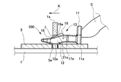
前記2つの部材の他方は前記パネル部材の突起部を挿通させる突起部挿通穴が設けられたパネル部材であり、
前記一方の部材における突起部の下端部には、該突起部が前記他方のパネル部材の突起部挿通穴に挿通されたときにその内壁面を内側から押圧する当てリブが設けられている。 More specifically, one of the two members is a panel member provided with a protrusion in the height direction, and the clip insertion hole is provided in the protrusion intersecting with the height direction,
The other of the two members is a panel member provided with a protrusion insertion hole through which the protrusion of the panel member is inserted,
At the lower end portion of the projecting portion of the one member, there is provided a contact rib that presses the inner wall surface from the inside when the projecting portion is inserted into the projecting portion insertion hole of the other panel member.
前記係止部が前記部材のクリップ挿通穴に挿通されたとき、前記第2開口縁部が前記段差部に入り込んで係合するようにしてもよい。 Then, a stepped step portion is provided in the second tapered portion,
When the locking portion is inserted into the clip insertion hole of the member, the second opening edge portion may enter and engage with the stepped portion.
(1)従来の締結手段の作業時間は約50秒であるが、本実施例のクリップの作業時間は約18秒であり、1回の作業時間が32秒短縮した。
(2)従来の締結手段は1つのスピーカにつき8個の部品が必要であるが、本実施例のクリップは1つのスピーカにつき4個の部品で済み、部品点数が半減した。
(3)従来の締結手段の重量は約44gであるが、本実施例のクリップの重量は約5.6gであり、重量が38.4g軽くなった。 The present applicant compared the speaker fixing work by the conventional fastening means (bolts and case nuts) with the speaker fixing work by the present clip, and obtained the following results.
(1) Although the work time of the conventional fastening means is about 50 seconds, the work time of the clip of this embodiment is about 18 seconds, and the work time for one time is reduced by 32 seconds.
(2) Although the conventional fastening means requires 8 parts per speaker, the clip of this embodiment only needs 4 parts per speaker, and the number of parts is reduced by half.
(3) Although the weight of the conventional fastening means is about 44 g, the weight of the clip of this embodiment is about 5.6 g, and the weight is reduced by 38.4 g.
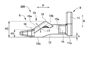
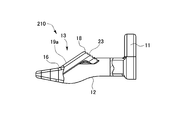
200~260 クリップ
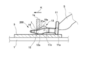
1 パネル(部材)
1a 突起部
5 パネル取付部(部材)
5a 突起部挿通穴
6 係止部
7 クリップ挿通穴
8 当てリブ
9 操作部
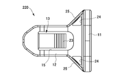
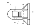
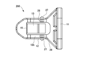
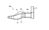
11 操作壁部(操作部)
11a 底面部
12 係止本体部(係止部)
12a 底面部
12b 上面部(挿通穴の内面と対向する部分)
13 爪部(第2押圧部)
14 接続部(接続部分、第1押圧部)
16 基端部
18 頂部
19a 前側傾斜面部(第1テーパ形状部)
19b 後側傾斜面部(第2押圧部、第2テーパ形状部)
21b 前側水平縁部(第1開口縁部)
22 垂直縁部(第2開口縁部)
23 段差部
25 薄肉部
27 爪部(突起部)
K 挿通方向
P 前後方向
Q 幅方向
R 高さ方向 100 Speaker 200-260
5a Protruding
12a
13 Claw part (second pressing part)
14 Connection part (connection part, 1st press part)
16
19b Rear inclined surface part (second pressing part, second tapered part)
21b Front horizontal edge (first opening edge)
22 Vertical edge (second opening edge)
23
K insertion direction P longitudinal direction Q width direction R height direction
Claims (12)
- 樹脂材よりなり、少なくとも2つの部材を締結するためのクリップであって、
前記2つの部材の少なくとも一方に設けられたクリップ挿通穴に押し込むために作業者によって操作される操作部と、前記クリップ挿通穴に押し込まれた状態で該クリップ挿通穴と係止する係止部と、を備え、
前記操作部と前記係止部との接続部分に前記クリップ挿通穴を内側から押圧する第1押圧部が設けられ、
前記係止部には、基端部を除く部分が係止部から分離され、その基端部を支点として弾性変形可能で、前記係止部から突出した部分が前記クリップ挿通穴を内側から押圧する第2押圧部が設けられ、
前記係止部が前記部材のクリップ挿通穴に挿通されたとき、前記操作部の底面部と前記係止部の底面部とが前記部材に当接した状態で、前記第1押圧部が前記クリップ挿通穴の第1開口縁部と密着し、前記第2押圧部が前記クリップ挿通穴の第2開口縁部と密着することを特徴とするクリップ。 A clip made of a resin material for fastening at least two members,
An operation unit operated by an operator to be pushed into a clip insertion hole provided in at least one of the two members, and a latching portion that is engaged with the clip insertion hole while being pushed into the clip insertion hole. With
A first pressing portion that presses the clip insertion hole from the inside is provided at a connection portion between the operation portion and the locking portion,
The locking portion is separated from the locking portion except for the base end portion, and can be elastically deformed with the base end portion as a fulcrum, and the portion protruding from the locking portion presses the clip insertion hole from the inside. A second pressing part is provided,
When the locking portion is inserted into the clip insertion hole of the member, the first pressing portion is the clip with the bottom surface portion of the operation portion and the bottom surface portion of the locking portion being in contact with the member. The clip, which is in close contact with the first opening edge of the insertion hole, and wherein the second pressing portion is in close contact with the second opening edge of the clip insertion hole. - 前記第2押圧部は断面三角形状であり、前記係止部の先端部から前記操作部に向かうにつれて、係止部からの突出長さが連続的に増大する第1テーパ形状部と、第2押圧部の頂部を介して第1テーパ形状部と接続し、前記操作部に向かうにつれて係止部からの突出長さが連続的に減少する第2テーパ形状部と、を備え、
前記第1押圧部が前記クリップ挿通穴の第1開口縁部と密着したとき、前記第2テーパ形状部が前記クリップ挿通穴の第2開口縁部と密着することを特徴とする請求の範囲第1項に記載のクリップ。 The second pressing portion has a triangular shape in cross section, and a first taper-shaped portion in which a protruding length from the locking portion continuously increases from the distal end portion of the locking portion toward the operation portion; A second taper-shaped portion that is connected to the first taper-shaped portion via the top of the pressing portion, and the protrusion length from the locking portion continuously decreases toward the operation portion;
The second taper-shaped portion is in close contact with the second opening edge of the clip insertion hole when the first pressing portion is in close contact with the first opening edge of the clip insertion hole. The clip according to item 1. - 前記操作部は方形板状であり、
前記係止部は、前記操作部の一方の面からその厚み方向に沿って延設する舌片形状であり、
前記操作部の底面部が水平面上に配置されたとき、前記係止部の底面部は、前記操作部の底面部よりも下方に配置されることを特徴とする請求の範囲第1項又は第2項に記載のクリップ。 The operation part is a square plate,
The locking portion has a tongue-like shape extending along the thickness direction from one surface of the operation portion,
2. The first or second claim, wherein the bottom surface portion of the locking portion is disposed below the bottom surface portion of the operation portion when the bottom surface portion of the operation portion is disposed on a horizontal plane. The clip according to item 2. - 前記操作部の底面部と前記係止部の底面部が同一の水平面に配置された状態で、前記第1押圧部において前記クリップ挿通穴の内周面を高さ方向に押圧する部分は、前記水平面に対して斜めになるように配置され、
前記斜めに配置された押圧部が前記クリップ挿通穴の内周面を斜め方向に押圧することにより、前記クリップ挿通穴を有する部材が斜めに傾くように弾性変形することを特徴とする請求の範囲第3項に記載のクリップ。 In a state where the bottom surface portion of the operation portion and the bottom surface portion of the locking portion are arranged on the same horizontal plane, the portion that presses the inner peripheral surface of the clip insertion hole in the height direction in the first pressing portion is Arranged so as to be oblique to the horizontal plane,
The member having the clip insertion hole is elastically deformed so that the member having the clip insertion hole is inclined by pressing the inner circumferential surface of the clip insertion hole in an oblique direction by the pressing portion disposed obliquely. The clip according to item 3. - 前記係止部の先端部は、幅方向及び/又は高さ方向に先細り形状となっていることを特徴とする請求の範囲第1項ないし第4項のいずれか1項に記載のクリップ。 The clip according to any one of claims 1 to 4, wherein a tip portion of the locking portion is tapered in a width direction and / or a height direction.
- 前記2つの部材の一方は高さ方向に突起部が設けられたパネル部材であり、前記突起部にはその高さ方向と交差する方向に前記クリップ挿通穴が設けられ、
前記2つの部材の他方は前記パネル部材の突起部を挿通させる突起部挿通穴が設けられたパネル部材であり、
前記一方の部材における突起部の下端部には、該突起部が前記他方のパネル部材の突起部挿通穴に挿通されたときにその内壁面を内側から押圧する当てリブが設けられていることを特徴とする請求の範囲第1項ないし第5項のいずれか1項に記載のクリップ。 One of the two members is a panel member provided with a protrusion in the height direction, and the clip insertion hole is provided in the protrusion intersecting with the height direction,
The other of the two members is a panel member provided with a protrusion insertion hole through which the protrusion of the panel member is inserted,
The lower end portion of the protruding portion of the one member is provided with a contact rib that presses the inner wall surface from the inside when the protruding portion is inserted into the protruding portion insertion hole of the other panel member. The clip according to any one of claims 1 to 5, wherein the clip is characterized by the following. - 前記当てリブの先端部に面取りが施されていることを特徴とする請求の範囲第6項に記載のクリップ。 The clip according to claim 6, wherein the tip of the abutment rib is chamfered.
- 前記第2テーパ形状部に階段状の段差部が設けられ、
前記係止部が前記部材のクリップ挿通穴に挿通されたとき、前記第2開口縁部が前記段差部に入り込んで係合することを特徴とする請求の範囲第2項ないし第7項のいずれか1項に記載のクリップ。 A stepped step portion is provided in the second tapered portion,
8. The device according to claim 2, wherein when the locking portion is inserted into the clip insertion hole of the member, the second opening edge portion enters and engages with the stepped portion. The clip according to claim 1. - 前記第1押圧部は、クリップの平面視において前記操作部の側に向かうにつれて幅方向に広がるテーパ形状となるように設けられ、かつ前記係止部が前記部材のクリップ挿通穴に挿通されて前記第1開口縁部と密着したときに弾性変形容易な薄肉部が形成されていることを特徴とする請求の範囲第1項ないし第8項のいずれか1項に記載のクリップ。 The first pressing portion is provided so as to have a tapered shape that expands in the width direction toward the operation portion in a plan view of the clip, and the locking portion is inserted into the clip insertion hole of the member. The clip according to any one of claims 1 to 8, wherein a thin-walled portion that is easily elastically deformed when being in close contact with the first opening edge is formed.
- 前記クリップ挿通穴の内周面には、前記部材のクリップ挿通穴に挿通されたクリップの前記係止部を押圧する突起部が設けられていることを特徴とする請求の範囲第1項ないし第9項のいずれか1項に記載のクリップ。 The protrusions that press the locking portion of the clip inserted into the clip insertion hole of the member are provided on the inner peripheral surface of the clip insertion hole. 10. The clip according to any one of items 9.
- 前記部材のうちの少なくとも1つには、振動を発生する部材が取り付けられていることを特徴とする請求の範囲第1項ないし第10項のいずれか1項に記載のクリップ。 The clip according to any one of claims 1 to 10, wherein a member that generates vibration is attached to at least one of the members.
- 前記振動を発生する部材は、車載用スピーカであることを特徴とする請求の範囲第11項に記載のクリップ。 The clip according to claim 11, wherein the member that generates vibration is an in-vehicle speaker.
Priority Applications (4)
| Application Number | Priority Date | Filing Date | Title |
|---|---|---|---|
| CN201080053830.0A CN102656375B (en) | 2009-11-30 | 2010-09-28 | Clip |
| EP10832968A EP2508765A1 (en) | 2009-11-30 | 2010-09-28 | Clip |
| JP2011543155A JP5620922B2 (en) | 2009-11-30 | 2010-09-28 | clip |
| US13/511,200 US8943655B2 (en) | 2009-11-30 | 2010-09-28 | Clip |
Applications Claiming Priority (2)
| Application Number | Priority Date | Filing Date | Title |
|---|---|---|---|
| JP2009271455 | 2009-11-30 | ||
| JP2009-271455 | 2009-11-30 |
Publications (1)
| Publication Number | Publication Date |
|---|---|
| WO2011065121A1 true WO2011065121A1 (en) | 2011-06-03 |
Family
ID=44066225
Family Applications (1)
| Application Number | Title | Priority Date | Filing Date |
|---|---|---|---|
| PCT/JP2010/066780 WO2011065121A1 (en) | 2009-11-30 | 2010-09-28 | Clip |
Country Status (5)
| Country | Link |
|---|---|
| US (1) | US8943655B2 (en) |
| EP (1) | EP2508765A1 (en) |
| JP (1) | JP5620922B2 (en) |
| CN (1) | CN102656375B (en) |
| WO (1) | WO2011065121A1 (en) |
Cited By (12)
| Publication number | Priority date | Publication date | Assignee | Title |
|---|---|---|---|---|
| WO2013161680A1 (en) * | 2012-04-26 | 2013-10-31 | 株式会社ニフコ | Clip |
| JP2013228069A (en) * | 2012-04-26 | 2013-11-07 | Honda Motor Co Ltd | Clip |
| WO2014051012A1 (en) * | 2012-09-28 | 2014-04-03 | 本田技研工業株式会社 | Vehicle component linking structure |
| JP2015033976A (en) * | 2013-08-09 | 2015-02-19 | 本田技研工業株式会社 | Fastening structure of members |
| JP2016043811A (en) * | 2014-08-22 | 2016-04-04 | トヨタ自動車株式会社 | Assembly structure for vehicle and method for manufacturing assembly part for vehicle |
| JP2016055808A (en) * | 2014-09-11 | 2016-04-21 | スズキ株式会社 | Garnish attachment structure |
| JP2016217390A (en) * | 2015-05-15 | 2016-12-22 | 株式会社ニフコ | clip |
| JP2018048718A (en) * | 2016-09-23 | 2018-03-29 | 株式会社ニフコ | Member attachment structure and attachment clip |
| JP2019006273A (en) * | 2017-06-26 | 2019-01-17 | 株式会社デンソーテン | Attachment structure of on-vehicle apparatus and attachment method |
| JP2019182164A (en) * | 2018-04-09 | 2019-10-24 | 大和化成工業株式会社 | Assembly structure of center console and method for assembly of center console |
| JP7280992B1 (en) | 2022-03-22 | 2023-05-24 | 三恵技研工業株式会社 | Clip installation structure |
| WO2023181617A1 (en) * | 2022-03-22 | 2023-09-28 | 三恵技研工業株式会社 | Attachment structure for hole sealing member |
Families Citing this family (23)
| Publication number | Priority date | Publication date | Assignee | Title |
|---|---|---|---|---|
| US9121426B2 (en) * | 2010-11-09 | 2015-09-01 | Illinois Tool Works Inc. | Bracket clip |
| JP5730129B2 (en) * | 2011-05-27 | 2015-06-03 | 本田技研工業株式会社 | Cowl fastening structure |
| JP5864391B2 (en) * | 2012-09-28 | 2016-02-17 | 株式会社ニフコ | clip |
| US10188179B2 (en) * | 2013-10-11 | 2019-01-29 | Aplix | Fastener |
| US9474338B2 (en) * | 2013-10-11 | 2016-10-25 | Aplix | Fastener |
| FR3014508B1 (en) * | 2013-12-06 | 2016-07-29 | Peugeot Citroen Automobiles Sa | DEVICE FOR SECURELY ATTACHING A PIECE TO A BODY OF A MOTOR VEHICLE BODY, WHICH MAY BE A REAR-LICENSE PLATE LIGHT BLOCK. |
| JP6111217B2 (en) * | 2014-04-02 | 2017-04-05 | 豊田鉄工株式会社 | Overlapped composite parts |
| US9676297B2 (en) * | 2015-02-18 | 2017-06-13 | Ford Global Technologies, Llc | Cantilever snap tab attachment device |
| DE102016004337A1 (en) * | 2016-04-13 | 2017-10-19 | A.RAYMOND et Cie. SCS | Clip for attaching a first element to a second element |
| US10865819B2 (en) * | 2016-05-20 | 2020-12-15 | Yazaki North America, Inc. | Tuneless cantilever system |
| CN107571813A (en) * | 2016-07-05 | 2018-01-12 | 福特环球技术公司 | Connection component, wire harness clip assembly and trim components for vehicle |
| US10328870B2 (en) * | 2016-07-25 | 2019-06-25 | Deere & Company | Work vehicle upholstery mounting system |
| US10513164B2 (en) * | 2017-02-09 | 2019-12-24 | Denso International America, Inc. | HVAC case fastener |
| US10464501B2 (en) * | 2017-09-21 | 2019-11-05 | GM Global Technology Operations LLC | Fastener for attaching a trim component to an inner structure of a vehicle |
| CN207961202U (en) * | 2018-01-08 | 2018-10-12 | 福特环球技术公司 | Sub- part and part assemblies |
| US11454263B2 (en) * | 2019-01-07 | 2022-09-27 | Illinois Tool Works Inc. | Systems and methods for a connector |
| CN110025168A (en) * | 2019-05-16 | 2019-07-19 | 深圳快品信息技术有限公司 | A kind of food and drink self-carry cabinet using rear-loading type main control unit |
| EP3742004B1 (en) * | 2019-05-22 | 2023-05-10 | DENSO THERMAL SYSTEMS S.p.A. | Connection device for interconnecting two components made of plastics material |
| US10857954B1 (en) * | 2019-07-29 | 2020-12-08 | Toyota Motor Engineering & Manufacturing North America, Inc. | Clip assemblies |
| JP7471120B2 (en) * | 2020-03-23 | 2024-04-19 | 株式会社ファルテック | Engagement Structure |
| KR102343026B1 (en) * | 2020-04-09 | 2021-12-23 | (주)엘엑스하우시스 | Structure for mounting garnish onto panel of vehicle |
| US11772577B2 (en) * | 2020-10-06 | 2023-10-03 | GM Global Technology Operations LLC | Serviceable shoe-clip fastener for vehicle trim attachment |
| CN112283216A (en) * | 2020-10-28 | 2021-01-29 | 浙江佳乐科仪股份有限公司 | Quick locking device |
Citations (5)
| Publication number | Priority date | Publication date | Assignee | Title |
|---|---|---|---|---|
| JPS57155308U (en) * | 1981-03-26 | 1982-09-29 | ||
| JPS6246736A (en) * | 1985-08-26 | 1987-02-28 | Nissan Motor Co Ltd | Attaching structure for external component |
| JPH074127U (en) * | 1993-06-16 | 1995-01-20 | フオスター電機株式会社 | Mounting structure of speaker for vehicle door |
| JP2002031110A (en) * | 2000-07-14 | 2002-01-31 | Nitto Electric Works Ltd | Clip for fixing panel |
| JP2002372011A (en) * | 2001-06-12 | 2002-12-26 | Mitsui Miike Mach Co Ltd | Fixture for plate member using wedge |
Family Cites Families (7)
| Publication number | Priority date | Publication date | Assignee | Title |
|---|---|---|---|---|
| JPS6256809U (en) * | 1985-09-30 | 1987-04-08 | ||
| JPH0353041Y2 (en) * | 1987-08-31 | 1991-11-19 | ||
| DE69615118T2 (en) * | 1995-09-19 | 2002-06-27 | Daiwa Kasei Kogyo K K | Leg for attaching a component |
| BR0010884A (en) * | 2000-03-24 | 2002-02-19 | Antolin Grupo Ing Sa | Metaloplastic clamp for fixing roofs and vehicle accessories to the vehicle body |
| JP4472456B2 (en) * | 2004-08-05 | 2010-06-02 | 株式会社ニフコ | Fastener |
| US7337505B1 (en) * | 2007-03-13 | 2008-03-04 | Illinois Tool Works Inc | Panel fastener |
| US9121426B2 (en) * | 2010-11-09 | 2015-09-01 | Illinois Tool Works Inc. | Bracket clip |
-
2010
- 2010-09-28 CN CN201080053830.0A patent/CN102656375B/en active Active
- 2010-09-28 WO PCT/JP2010/066780 patent/WO2011065121A1/en active Application Filing
- 2010-09-28 US US13/511,200 patent/US8943655B2/en active Active
- 2010-09-28 EP EP10832968A patent/EP2508765A1/en not_active Withdrawn
- 2010-09-28 JP JP2011543155A patent/JP5620922B2/en active Active
Patent Citations (5)
| Publication number | Priority date | Publication date | Assignee | Title |
|---|---|---|---|---|
| JPS57155308U (en) * | 1981-03-26 | 1982-09-29 | ||
| JPS6246736A (en) * | 1985-08-26 | 1987-02-28 | Nissan Motor Co Ltd | Attaching structure for external component |
| JPH074127U (en) * | 1993-06-16 | 1995-01-20 | フオスター電機株式会社 | Mounting structure of speaker for vehicle door |
| JP2002031110A (en) * | 2000-07-14 | 2002-01-31 | Nitto Electric Works Ltd | Clip for fixing panel |
| JP2002372011A (en) * | 2001-06-12 | 2002-12-26 | Mitsui Miike Mach Co Ltd | Fixture for plate member using wedge |
Cited By (17)
| Publication number | Priority date | Publication date | Assignee | Title |
|---|---|---|---|---|
| WO2013161680A1 (en) * | 2012-04-26 | 2013-10-31 | 株式会社ニフコ | Clip |
| JP2013228069A (en) * | 2012-04-26 | 2013-11-07 | Honda Motor Co Ltd | Clip |
| JP2013228068A (en) * | 2012-04-26 | 2013-11-07 | Nifco Inc | Clip |
| CN104254695A (en) * | 2012-04-26 | 2014-12-31 | 株式会社利富高 | Clip |
| WO2014051012A1 (en) * | 2012-09-28 | 2014-04-03 | 本田技研工業株式会社 | Vehicle component linking structure |
| JP2014069733A (en) * | 2012-09-28 | 2014-04-21 | Honda Motor Co Ltd | Connection structure of vehicle component |
| JP2015033976A (en) * | 2013-08-09 | 2015-02-19 | 本田技研工業株式会社 | Fastening structure of members |
| JP2016043811A (en) * | 2014-08-22 | 2016-04-04 | トヨタ自動車株式会社 | Assembly structure for vehicle and method for manufacturing assembly part for vehicle |
| JP2016055808A (en) * | 2014-09-11 | 2016-04-21 | スズキ株式会社 | Garnish attachment structure |
| JP2016217390A (en) * | 2015-05-15 | 2016-12-22 | 株式会社ニフコ | clip |
| JP2018048718A (en) * | 2016-09-23 | 2018-03-29 | 株式会社ニフコ | Member attachment structure and attachment clip |
| JP2019006273A (en) * | 2017-06-26 | 2019-01-17 | 株式会社デンソーテン | Attachment structure of on-vehicle apparatus and attachment method |
| JP2019182164A (en) * | 2018-04-09 | 2019-10-24 | 大和化成工業株式会社 | Assembly structure of center console and method for assembly of center console |
| JP7042147B2 (en) | 2018-04-09 | 2022-03-25 | 大和化成工業株式会社 | Center console assembly structure and center console assembly method |
| JP7280992B1 (en) | 2022-03-22 | 2023-05-24 | 三恵技研工業株式会社 | Clip installation structure |
| WO2023181617A1 (en) * | 2022-03-22 | 2023-09-28 | 三恵技研工業株式会社 | Attachment structure for hole sealing member |
| WO2023181618A1 (en) * | 2022-03-22 | 2023-09-28 | 三恵技研工業株式会社 | Clip installation structure |
Also Published As
| Publication number | Publication date |
|---|---|
| CN102656375A (en) | 2012-09-05 |
| JP5620922B2 (en) | 2014-11-05 |
| US20120227219A1 (en) | 2012-09-13 |
| US8943655B2 (en) | 2015-02-03 |
| CN102656375B (en) | 2014-06-25 |
| JPWO2011065121A1 (en) | 2013-04-11 |
| EP2508765A1 (en) | 2012-10-10 |
Similar Documents
| Publication | Publication Date | Title |
|---|---|---|
| JP5620922B2 (en) | clip | |
| US7120971B2 (en) | Low insertion effort u-base retainer | |
| US7114221B2 (en) | Two-piece interior trim retainer | |
| US8591160B2 (en) | Clip | |
| JP2005188718A (en) | Clip | |
| JP4260159B2 (en) | Mounting structure of vehicle pillar garnish | |
| JP2007315467A (en) | Component attaching device | |
| JP2014228112A (en) | Mounting structure for mounting member | |
| JP5182497B2 (en) | Radiator grille mounting structure and method for removing radiator grille | |
| JP2018132140A (en) | Fixture for sheet-like member | |
| JP2011252525A (en) | Parts fitting structure | |
| JP2007110806A (en) | Fixing tool | |
| JP2007181363A (en) | Fixture | |
| JP2008247233A (en) | Locking hook structure of resinous component | |
| JP2006214479A (en) | Fitting structure for resin member | |
| JP2014055641A (en) | Component engagement structure | |
| JP2008110650A (en) | Mounting structure of vehicular audio device and mounting bracket, its mounting bracket and assembling structure for mounting bracket and article to be assembled | |
| JP4497071B2 (en) | Mounting structure of vehicle pillar garnish | |
| JP2005162046A (en) | Mounting bracket for on-vehicle electronic control parts | |
| JP2007331618A (en) | Installation structure for spoiler in vehicle | |
| JP4777318B2 (en) | Electrical device mounting structure, electrical device mounting frame, and electrical device mounting method | |
| JP4245935B2 (en) | Assist grip mounting structure | |
| JP5370849B2 (en) | clip | |
| JP4753894B2 (en) | Resin parts assembly structure | |
| JP2008068654A (en) | Mesh material attachment structure for vehicle |
Legal Events
| Date | Code | Title | Description |
|---|---|---|---|
| WWE | Wipo information: entry into national phase |
Ref document number: 201080053830.0 Country of ref document: CN |
|
| 121 | Ep: the epo has been informed by wipo that ep was designated in this application |
Ref document number: 10832968 Country of ref document: EP Kind code of ref document: A1 |
|
| WWE | Wipo information: entry into national phase |
Ref document number: 13511200 Country of ref document: US |
|
| WWE | Wipo information: entry into national phase |
Ref document number: 2011543155 Country of ref document: JP |
|
| WWE | Wipo information: entry into national phase |
Ref document number: 2010832968 Country of ref document: EP |
|
| NENP | Non-entry into the national phase |
Ref country code: DE |
|
| WWE | Wipo information: entry into national phase |
Ref document number: 1201002403 Country of ref document: TH |