WO2011062069A1 - コバルト膜形成用材料及びコバルト膜形成方法 - Google Patents
コバルト膜形成用材料及びコバルト膜形成方法 Download PDFInfo
- Publication number
- WO2011062069A1 WO2011062069A1 PCT/JP2010/069676 JP2010069676W WO2011062069A1 WO 2011062069 A1 WO2011062069 A1 WO 2011062069A1 JP 2010069676 W JP2010069676 W JP 2010069676W WO 2011062069 A1 WO2011062069 A1 WO 2011062069A1
- Authority
- WO
- WIPO (PCT)
- Prior art keywords
- group
- cobalt film
- film forming
- cobalt
- forming material
- Prior art date
- Legal status (The legal status is an assumption and is not a legal conclusion. Google has not performed a legal analysis and makes no representation as to the accuracy of the status listed.)
- Ceased
Links
Classifications
-
- C—CHEMISTRY; METALLURGY
- C23—COATING METALLIC MATERIAL; COATING MATERIAL WITH METALLIC MATERIAL; CHEMICAL SURFACE TREATMENT; DIFFUSION TREATMENT OF METALLIC MATERIAL; COATING BY VACUUM EVAPORATION, BY SPUTTERING, BY ION IMPLANTATION OR BY CHEMICAL VAPOUR DEPOSITION, IN GENERAL; INHIBITING CORROSION OF METALLIC MATERIAL OR INCRUSTATION IN GENERAL
- C23C—COATING METALLIC MATERIAL; COATING MATERIAL WITH METALLIC MATERIAL; SURFACE TREATMENT OF METALLIC MATERIAL BY DIFFUSION INTO THE SURFACE, BY CHEMICAL CONVERSION OR SUBSTITUTION; COATING BY VACUUM EVAPORATION, BY SPUTTERING, BY ION IMPLANTATION OR BY CHEMICAL VAPOUR DEPOSITION, IN GENERAL
- C23C16/00—Chemical coating by decomposition of gaseous compounds, without leaving reaction products of surface material in the coating, i.e. chemical vapour deposition [CVD] processes
- C23C16/06—Chemical coating by decomposition of gaseous compounds, without leaving reaction products of surface material in the coating, i.e. chemical vapour deposition [CVD] processes characterised by the deposition of metallic material
- C23C16/18—Chemical coating by decomposition of gaseous compounds, without leaving reaction products of surface material in the coating, i.e. chemical vapour deposition [CVD] processes characterised by the deposition of metallic material from metallo-organic compounds
-
- C—CHEMISTRY; METALLURGY
- C07—ORGANIC CHEMISTRY
- C07F—ACYCLIC, CARBOCYCLIC OR HETEROCYCLIC COMPOUNDS CONTAINING ELEMENTS OTHER THAN CARBON, HYDROGEN, HALOGEN, OXYGEN, NITROGEN, SULFUR, SELENIUM OR TELLURIUM
- C07F15/00—Compounds containing elements of Groups 8, 9, 10 or 18 of the Periodic Table
- C07F15/06—Cobalt compounds
-
- C—CHEMISTRY; METALLURGY
- C23—COATING METALLIC MATERIAL; COATING MATERIAL WITH METALLIC MATERIAL; CHEMICAL SURFACE TREATMENT; DIFFUSION TREATMENT OF METALLIC MATERIAL; COATING BY VACUUM EVAPORATION, BY SPUTTERING, BY ION IMPLANTATION OR BY CHEMICAL VAPOUR DEPOSITION, IN GENERAL; INHIBITING CORROSION OF METALLIC MATERIAL OR INCRUSTATION IN GENERAL
- C23C—COATING METALLIC MATERIAL; COATING MATERIAL WITH METALLIC MATERIAL; SURFACE TREATMENT OF METALLIC MATERIAL BY DIFFUSION INTO THE SURFACE, BY CHEMICAL CONVERSION OR SUBSTITUTION; COATING BY VACUUM EVAPORATION, BY SPUTTERING, BY ION IMPLANTATION OR BY CHEMICAL VAPOUR DEPOSITION, IN GENERAL
- C23C16/00—Chemical coating by decomposition of gaseous compounds, without leaving reaction products of surface material in the coating, i.e. chemical vapour deposition [CVD] processes
- C23C16/06—Chemical coating by decomposition of gaseous compounds, without leaving reaction products of surface material in the coating, i.e. chemical vapour deposition [CVD] processes characterised by the deposition of metallic material
- C23C16/16—Chemical coating by decomposition of gaseous compounds, without leaving reaction products of surface material in the coating, i.e. chemical vapour deposition [CVD] processes characterised by the deposition of metallic material from metal carbonyl compounds
-
- H—ELECTRICITY
- H10—SEMICONDUCTOR DEVICES; ELECTRIC SOLID-STATE DEVICES NOT OTHERWISE PROVIDED FOR
- H10P—GENERIC PROCESSES OR APPARATUS FOR THE MANUFACTURE OR TREATMENT OF DEVICES COVERED BY CLASS H10
- H10P14/00—Formation of materials, e.g. in the shape of layers or pillars
- H10P14/40—Formation of materials, e.g. in the shape of layers or pillars of conductive or resistive materials
- H10P14/42—Formation of materials, e.g. in the shape of layers or pillars of conductive or resistive materials using a gas or vapour
- H10P14/43—Chemical deposition, e.g. chemical vapour deposition [CVD]
-
- H—ELECTRICITY
- H10—SEMICONDUCTOR DEVICES; ELECTRIC SOLID-STATE DEVICES NOT OTHERWISE PROVIDED FOR
- H10W—GENERIC PACKAGES, INTERCONNECTIONS, CONNECTORS OR OTHER CONSTRUCTIONAL DETAILS OF DEVICES COVERED BY CLASS H10
- H10W20/00—Interconnections in chips, wafers or substrates
- H10W20/01—Manufacture or treatment
- H10W20/031—Manufacture or treatment of conductive parts of the interconnections
- H10W20/032—Manufacture or treatment of conductive parts of the interconnections of conductive barrier, adhesion or liner layers
- H10W20/033—Manufacture or treatment of conductive parts of the interconnections of conductive barrier, adhesion or liner layers in openings in dielectrics
-
- H—ELECTRICITY
- H10—SEMICONDUCTOR DEVICES; ELECTRIC SOLID-STATE DEVICES NOT OTHERWISE PROVIDED FOR
- H10W—GENERIC PACKAGES, INTERCONNECTIONS, CONNECTORS OR OTHER CONSTRUCTIONAL DETAILS OF DEVICES COVERED BY CLASS H10
- H10W20/00—Interconnections in chips, wafers or substrates
- H10W20/01—Manufacture or treatment
- H10W20/031—Manufacture or treatment of conductive parts of the interconnections
- H10W20/032—Manufacture or treatment of conductive parts of the interconnections of conductive barrier, adhesion or liner layers
- H10W20/042—Manufacture or treatment of conductive parts of the interconnections of conductive barrier, adhesion or liner layers the barrier, adhesion or liner layers being seed or nucleation layers
- H10W20/043—Manufacture or treatment of conductive parts of the interconnections of conductive barrier, adhesion or liner layers the barrier, adhesion or liner layers being seed or nucleation layers for electroplating
Definitions
- the present invention relates to a cobalt film forming material and a cobalt film forming method.
- a semiconductor device typified by a DRAM Dynamic Random Access Memory
- DRAM Dynamic Random Access Memory
- improvement of the conductive metal film for the multilayer wiring use in the semiconductor device is required, and the conversion to copper wiring with high conductivity is newly advanced.
- a low dielectric constant material (Low-k material) is used for the interlayer insulating film material of the multilayer wiring.
- oxygen atoms contained in the low dielectric constant material are easily taken into the copper wiring and the conductivity is lowered.
- a technique for forming a barrier film between the low dielectric constant material and the copper wiring has been studied.
- a metal cobalt film has been attracting attention as a material that is difficult to take up oxygen from a dielectric layer and a material that can be easily processed by dry etching, which are used for the barrier film.
- metallic cobalt has attracted attention for the purpose of satisfying both roles of the barrier film and the plating growth film at the same time.
- Patent Document 1 a method for forming a cobalt film using octacarbonyl dicobalt has been proposed.
- the compound (octacarbonyl dicobalt) has a problem that it is unstable in the atmosphere.
- the present invention has been made in view of the above problems, and an object thereof is to provide a cobalt film forming material that is stable in the atmosphere and a cobalt film forming method using the material.
- a cobalt film forming material containing a compound represented by the following formula (1) [1] to [9].
- Z represents a hydrogen atom, a halogen atom, a hydrocarbon group having 1 to 10 carbon atoms which may be substituted with a halogen atom, or a carbon atom having 1 to 10 carbon atoms which may be substituted with a halogen atom.
- [3] The material for forming a cobalt film according to [1], wherein Z in the general formula (1) is an alkoxycarbonyl group having 2 to 10 carbon atoms which may be substituted with a halogen atom.
- Z in the general formula (1) is an alkoxycarbonyl group having 2 to 10 carbon atoms which may be substituted with a halogen atom.
- [5] A cobalt film forming method using the cobalt film forming material according to any one of [1] to [4].
- [6] A cobalt film forming material supply step for supplying the cobalt film forming material described in [1] to [4] onto the substrate, and a thermal decomposition of the cobalt film forming material supplied on the substrate.
- a film forming step of forming a cobalt film on the substrate [7] The cobalt film forming method according to the above [6], wherein the thermal decomposition temperature in the film forming step is 100 ° C. to 800 ° C. [8] The cobalt film forming method according to [6] or [7], wherein the thermal decomposition in the film forming step is performed in an inert gas or a reducing gas. [9] A film in which the cobalt film-forming material according to any one of [1] to [3] is applied on a substrate, and then heat-treated and / or light-treated to form a cobalt film on the substrate. A cobalt film forming method including a forming step.
- the cobalt film of the present invention Since the material for forming a cobalt film of the present invention is stable in the air and excellent in handleability, the cobalt film can be formed by a simple method.
- the cobalt film forming material of the present invention is represented by the following formula (1).
- Z is a hydrogen atom, a halogen atom, a hydrocarbon group having 1 to 10 carbon atoms which may be substituted with a halogen atom, or a carbon atom having 1 to 10 carbon atoms which may be substituted with a halogen atom.
- An alkoxycarbonyl group having 2 to 10 carbon atoms, and an alkoxyalkyl group having 2 to 10 carbon atoms which may be substituted with a halogen atom an alkoxycarbonyl group having 2 to 10 carbon atoms, and an alkoxyalkyl group having 2 to 10 carbon atoms which may be substituted with a halogen atom.
- Z is a compound having 1 to 4 carbon atoms that may be substituted with a halogen atom from the viewpoint that the melting point of the compound is low and the cobalt film forming material can be easily supplied onto the substrate during the formation of the cobalt film.
- An alkoxycarbonyl group having 2 to 4 carbon atoms and an alkoxyalkyl group having 2 to 4 carbon atoms which may be substituted with a halogen atom are preferable.
- examples of the halogen atom include a fluorine atom, a chlorine atom, a bromine atom, and an iodine atom.
- a fluorine atom and a chlorine atom are preferable, and a fluorine atom is more preferable.
- the hydrocarbon group having 1 to 10 carbon atoms in Z has a high vapor pressure of the compound, and from the viewpoint that the cobalt film forming material can be easily supplied onto the substrate during the formation of the cobalt film.
- a hydrocarbon group having 1 to 8 carbon atoms is preferable, and a hydrocarbon group having 1 to 4 carbon atoms is more preferable.
- aliphatic hydrocarbon groups such as methyl group, ethyl group, n-propyl group, isopropyl group, n-butyl group, isobutyl group and t-butyl group, cyclopropyl group, cyclobutyl group, cyclopentyl group, cyclohexyl
- aromatic hydrocarbon groups such as phenyl group, methylphenyl group, ethylphenyl group and benzyl group, such as methyl group, ethyl group, n-propyl group, isopropyl group, A t-butyl group, a phenyl group, and a methylphenyl group are preferable, and a methyl group and an ethyl group are more preferable.
- hydrocarbon group having 1 to 10 carbon atoms in which at least a part of hydrogen atoms in Z are substituted with halogen atoms include fluorinated hydrocarbon groups, chlorinated hydrocarbon groups, and brominated hydrocarbon groups. More preferably, it is a fluorinated hydrocarbon group.
- the hydrocarbon group preferably has 1 to 4 carbon atoms from the viewpoint that the vapor pressure of the compound is high and the cobalt film forming material can be easily supplied onto the substrate during the formation of the cobalt film.
- the alkoxy group having 1 to 10 carbon atoms in Z the vapor pressure of the compound is high, and from the viewpoint that the cobalt film forming material can be easily supplied onto the substrate during the formation of the cobalt film, the number of carbon atoms is 1 Is preferably an alkoxy group of 1 to 4, specifically, a methoxy group, an ethoxy group, an n-propoxy group, an isopropoxy group, an n-butoxy group, an isobutoxy group, a t-butoxy group, and a methoxy group, An ethoxy group, an n-propoxy group, and an isopropoxy group are preferable, and a methoxy group and an ethoxy group are more preferable.
- Examples of the alkoxy group having 1 to 10 carbon atoms in which at least a part of hydrogen atoms in Z are substituted with halogen atoms include fluorinated alkoxy groups, chlorinated alkoxy groups, and brominated alkoxy groups. It is more preferable that The number of carbon atoms of the alkoxy group is preferably 1 to 4 from the viewpoint that the vapor pressure of the compound is high and the cobalt film forming material can be easily supplied onto the substrate during the formation of the cobalt film.
- the acyl group having 2 to 10 carbon atoms has a high vapor pressure of the compound, and from the viewpoint that the cobalt film forming material can be easily supplied onto the substrate during the formation of the cobalt film, the number of carbon atoms is 2.
- Acyl groups of ⁇ 5 are preferred.
- the acyl group may be either an aliphatic acyl group or an aromatic acyl group.
- aliphatic acyl group examples include, for example, acetyl group, propionyl group, butyryl group, valeryl group, cyclopropylcarbonyl group, cyclobutylcarbonyl group, cyclopentylcarbonyl group, cyclohexylcarbonyl group and the like.
- aromatic acyl group examples include a benzoyl group, a methylphenylcarbonyl group, and an ethylphenylcarbonyl group.
- examples of the acyl group having 2 to 10 carbon atoms in which at least a part of hydrogen atoms in Z are substituted with halogen atoms include fluorinated acyl groups, chlorinated acyl groups, and brominated acyl groups. It is preferable that Further, the carbon number of the acyl group is preferably 2 to 5 from the viewpoint that the vapor pressure of the compound is high and that the cobalt film forming material can be easily supplied onto the substrate when forming the cobalt film.
- Preferable specific examples include a trifluoroacetyl group, a pentafluoropropionyl group, a heptafluorobutyryl group, and the like.
- the alkylamide group having 1 to 10 carbon atoms in Z has a high vapor pressure of the compound, and from the viewpoint that the cobalt film forming material can be easily supplied onto the substrate during the formation of the cobalt film. It is preferably 1 to 6, and specific examples include methylamide group, dimethylamide group, ethylamide group, diethylamide group, propylamide group, dipropylamide group, butyramide group, dibutylamide group and the like.
- alkylamide group having 1 to 10 carbon atoms in which at least a part of hydrogen atoms in Z are substituted with halogen atoms examples include fluorinated alkylamide groups, chlorinated alkylamide groups, and brominated alkylamide groups.
- a fluorinated alkylamide group is preferred.
- the number of carbon atoms of the alkylamide group is preferably 1 to 4 from the viewpoint that the vapor pressure of the compound is high and the supply of the material for forming the cobalt film onto the substrate can be facilitated when forming the cobalt film. .
- Preferred examples include chloromethylamide group, dichloromethylamide group, trichloromethylamide group, fluoromethylamide group, difluoromethylamide group, trifluoromethylamide group, 2-chloroethylamide group, 2,2-dichloro Ethylamide group, 2,2,2-trichloroethylamide group, 2-fluoroethylamide group, 2,2-difluoroethylamide group, 2,2,2-trifluoroethylamide group, pentafluoroethylamide group, etc. Can be mentioned.
- Examples of the C2-C10 alkoxycarbonyl group in which at least a part of hydrogen atoms in Z are substituted with halogen atoms include fluorinated alkoxycarbonyl groups, chlorinated alkoxycarbonyl groups, and brominated alkoxycarbonyl groups. More preferably, it is a fluorinated alkoxycarbonyl group.
- the number of carbon atoms of the halogenated alkoxycarbonyl group is preferably 2 to 5 from the viewpoint that the vapor pressure of the compound is high and the cobalt film forming material can be easily supplied onto the substrate when forming the cobalt film. is there.
- chloromethoxycarbonyl group dichloromethoxycarbonyl group, trichloromethoxycarbonyl group, fluoromethoxycarbonyl group, difluoromethoxycarbonyl group, trifluoromethoxycarbonyl group, 2,2,2-trifluoroethoxycarbonyl group, pentafluoro
- Examples thereof include ethoxycarbonyl group, perfluoro-n-propoxycarbonyl group, perfluoroisopropoxycarbonyl group, perfluoro-n-butoxycarbonyl group, perfluoroisobutoxycarbonyl group, perfluoro-t-butoxycarbonyl group, fluoromethoxycarbonyl group, Difluoromethoxycarbonyl group, trifluoromethoxycarbonyl group, 2,2,2-trifluoroethoxycarbonyl group, pentafluoroethoxycal Nyl group, perfluoro-n-propoxycarbonyl group, perfluoroisopropoxycarbonyl group, and perfluor
- Fluoromethoxycarbonyl group difluoromethoxycarbonyl group, trifluoromethoxycarbonyl group, 2,2, More preferred are 2-trifluoroethoxycarbonyl group and pentafluoroethoxycarbonyl group.
- the alkoxyalkyl group having 2 to 10 carbon atoms has a high vapor pressure of the compound, and from the viewpoint that the cobalt film forming material can be easily supplied onto the substrate during the formation of the cobalt film,
- An alkoxyalkyl group having 8 carbon atoms is preferable, and an alkoxyalkyl group having 2 to 4 carbon atoms is more preferable.
- Specific examples include methoxymethyl group, methoxyethyl group, methoxypropyl group, methoxybutyl group, ethoxymethyl group, ethoxyethyl group, ethoxypropyl group, ethoxybutyl group, and the like.
- a propyl group, an ethoxymethyl group, and an ethoxyethyl group are more preferable.
- alkoxyalkyl group having 2 to 10 carbon atoms in which at least a part of hydrogen atoms in Z are substituted with halogen atoms include fluorinated alkoxyalkyl groups, chlorinated alkoxyalkyl groups, and brominated alkoxyalkyl groups.
- An alkoxyalkyl group is preferred.
- the number of carbon atoms of the alkoxyalkyl group is preferably 2 to 8, more preferably from the viewpoint that the vapor pressure of the compound is high and the cobalt film forming material can be easily supplied onto the substrate during the formation of the cobalt film. Preferably it is 2-4.
- Preferred examples include chloromethoxymethyl group, chloromethoxyethyl group, chloromethoxypropyl group, chloromethoxybutyl group, 2,2,2-trichloroethoxymethyl group, pentachloroethoxymethyl group, 2,2,2- Trichloroethoxyethyl group, pentachloroethoxyethyl group, fluoromethoxymethyl group, fluoromethoxyethyl group, fluoromethoxypropyl group, fluoromethoxybutyl group, 2,2,2-trifluoroethoxymethyl group, pentafluoroethoxymethyl group, 2 2,2-trifluoroethoxyethyl group, pentafluoroethoxyethyl group, etc., such as fluoromethoxymethyl group, fluoromethoxyethyl group, fluoromethoxypropyl group, 2,2,2-trifluoroethoxymethyl group, pentafluoro D Kishimechiru group, 2,2,2-triflu
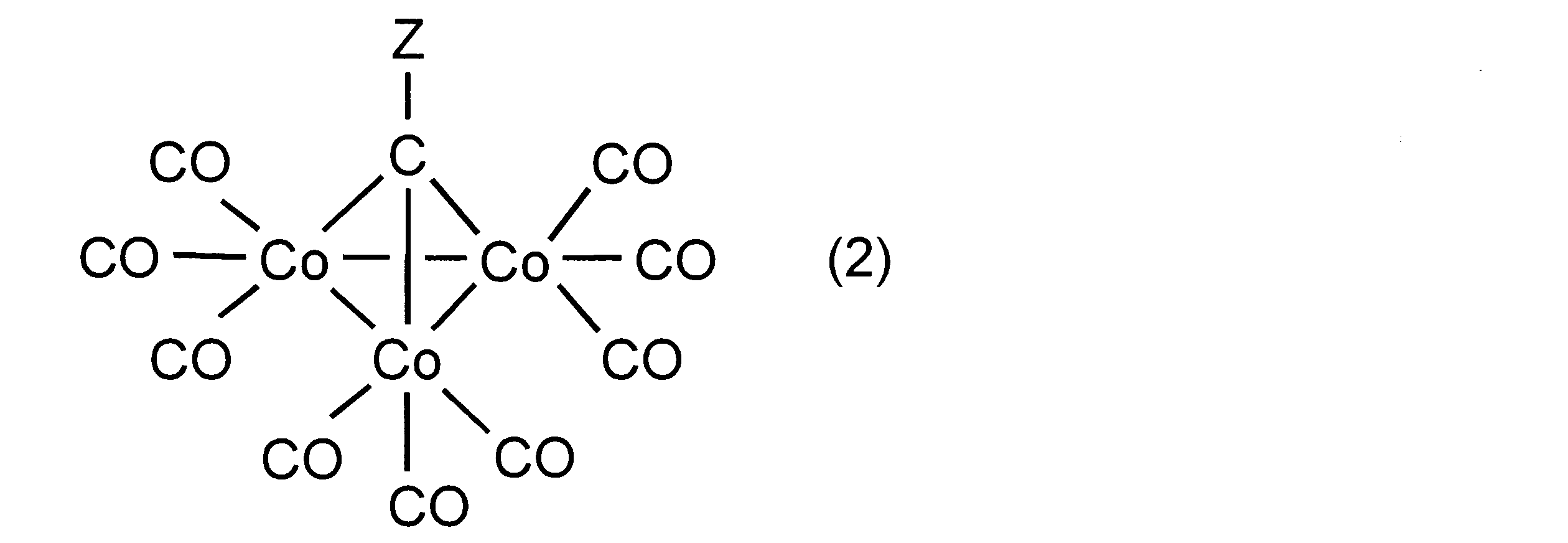
- the compound represented by the above formula (1) is preferably a compound having a structure represented by the following formula (2).
- Specific examples of the compound represented by the above formula (1) include, for example, nonacarbonyl- ⁇ 3 -methylidyne tricobalt, nonacarbonyl- ⁇ 3 -ethylidene tricobalt, nonacarbonyl- ⁇ 3 -ethoxycarbonylmethylidyne.
- Tricobalt nonacarbonyl- ⁇ 3 -t-butoxycarbonylmethylidyne tricobalt, nonacarbonyl- ⁇ 3 -diethylamidomethylidyne tricobalt, nonacarbonyl- ⁇ 3 -n-propylcarbonylmethylidyne tricobalt, nonacarbonyl- ⁇ 3 -Phenylcarbonylmethylidyne tricobalt, nonacarbonyl- ⁇ 3 -4-methylphenylcarbonylmethylidyne tricobalt, nonacarbonyl- ⁇ 3 -2,2,2-trifluoroethoxycarbonylmethylidyne tricobalt, nonacarbonyl- ⁇ 3 -2, 2 3,3,4,4,5,5-octafluoropentoxycarbonylmethylidyne tricobalt, nonacarbonyl- ⁇ 3 -2-methylbutoxycarbonylmethylidyne trico
- These compounds can be used alone or in combination of two or more as a material for forming a cobalt film. Since it is easy to set the film forming conditions, it is preferable to use one kind of compound alone as a material for forming a cobalt film.
- the cobalt film forming material of the present invention can be used by dissolving in a solvent.
- the solvent used is not particularly limited as long as it dissolves the compound represented by the above formula (1).
- examples of such solvents include hydrocarbon solvents, halogenated hydrocarbon solvents, ether solvents, alcohol solvents. And ketone solvents.
- hydrocarbon solvent examples include n-pentane, cyclopentane, n-hexane, cyclohexane, n-heptane, cycloheptane, n-octane, cyclooctane, decane, cyclodecane, dicyclopentadiene hydride, benzene, toluene, Examples include xylene, durene, indene, tetrahydronaphthalene, decahydronaphthalene and the like.
- halogenated hydrocarbon solvent examples include dimethyl dichloride, chloroform, carbon tetrachloride, tetrachloroethane, chlorobenzene, dichlorobenzene, tetrachlorobenzene, bromobenzene, and fluorobenzene.
- ether solvent examples include diethyl ether, dipropyl ether, dibutyl ether, ethylene glycol dimethyl ether, ethylene glycol diethyl ether, ethylene glycol methyl ethyl ether, diethylene glycol dimethyl ether, diethylene glycol diethyl ether, diethylene glycol methyl ethyl ether, tetrahydrofuran, tetrahydropyran, and bis.
- the alcohol solvent examples include methanol, ethanol, n-propanol, i-propanol, allyl alcohol, n-butanol, i-butanol, t-butanol, n-heptanol, octanol, diethylene glycol, 1,2-butanediol, 1 , 3-butanediol, propylene glycol, cyclopentanol, cyclohexanol, phenol, 3-chloro-1-propanol and the like.
- ester solvent examples include ethyl acetate, methyl acetate, vinyl acetate, methyl methacrylate, ethyl chloroacetate, ethyl acetoacetate, chlorocarbonic acid methyl ester, and chlorocarbonic acid ethyl ester.
- ketone solvent examples include acetone, methyl ethyl ketone, acetyl acetone, diethyl ketone, methyl hexyl ketone, and cyclohexanone. These solvents can be used alone or in admixture of two or more.
- a hydrocarbon solvent an ether solvent, an ester solvent, a ketone solvent, and a mixed solvent thereof in combination from the viewpoints of solubility and stability of the resulting composition solution.
- cyclohexane, n-heptane, cycloheptane, n-octane, benzene, toluene or xylene as the hydrocarbon solvent.
- ether solvents diethyl ether, dipropyl ether, dibutyl ether, ethylene glycol diethyl ether, ethylene glycol methyl ethyl ether, tetrahydrofuran, tetrahydropyran, anisole, 2-methylanisole, 3-methylanisole, 4-methylanisole, fentol
- veratrol, 2-ethoxyanisole or 1,4-dimethoxybenzene is used.
- ethyl acetate it is preferable to use acetone, methyl ethyl ketone, and acetylacetone as the ketone solvent.
- the ratio of the total mass of the components excluding the solvent to the total mass of the cobalt film forming material (hereinafter referred to as “solid content concentration”) is as follows.
- the amount is preferably 1 to 80% by mass, and more preferably 20 to 60% by mass.
- the cobalt film forming material of the present invention can contain other cobalt compounds in addition to the compound represented by the above formula (1).
- Other cobalt compounds include octacarbonyl dicobalt and the like.
- the compound represented by the formula (1) is preferably 30 to 100% by mass, more preferably 50% to 100% by mass with respect to the total of components excluding the solvent. %, More preferably 70% by mass to 100% by mass, further preferably 80% by mass to 100% by mass, and particularly preferably 90% by mass to 100% by mass.
- the cobalt film forming method of the present invention uses the above-described cobalt film forming material.
- the method for forming a cobalt film of the present invention can be a method known per se except that the above-described material for forming a cobalt film is used.
- the method can be carried out as follows.
- An example of the cobalt film formation method of the present invention is as follows: (1) The cobalt film formation material of the present invention is vaporized or sublimated under reduced pressure and heating, and the vaporized product or sublimated product is supplied onto a substrate (for example, a substrate). And (2) a step of heating and thermally decomposing the cobalt film forming material supplied onto the substrate to form a cobalt film on the substrate. In addition, even if it decomposes
- a material of the substrate that can be used here, for example, glass, silicon semiconductor, quartz, metal, metal oxide, synthetic resin, and other suitable materials can be used. However, the material can withstand the process temperature for thermally decomposing the cobalt compound. It is preferable.
- the substrate is composed of a metal film such as Ta, Ti, Zr, Hf, Pt, Ir, Cu, Au, and Al, a metal nitride film such as TaN, TiN, ZrN, and AlN, or an insulating film.
- a metal film such as Ta, Ti, Zr, Hf, Pt, Ir, Cu, Au, and Al
- a metal nitride film such as TaN, TiN, ZrN, and AlN
- an insulating film include a thermal oxide film, a PETEOS film (Plasma Enhanced-TEOS film), an HDP film (High Density Plasma Enhanced-TEOS film), a silicon oxide film obtained by a thermal CVD method, and a boron phosphorus silicate film (BPSG film). ), An insulating film called FSG, an insulating film having a low dielectric constant, and the like.
- the thermal oxide film is formed by exposing high temperature silicon to an oxidizing atmosphere and chemically reacting silicon and oxygen or silicon and moisture.
- the PETEOS film is formed by chemical vapor deposition using tetraethylorthosilicate (TEOS) as a raw material and using plasma as an acceleration condition.
- the HDP film is formed by chemical vapor deposition using tetraethylorthosilicate (TEOS) as a raw material and using high-density plasma as a promotion condition.
- the silicon oxide film obtained by the thermal CVD method is formed by an atmospheric pressure CVD method (AP-CVD method) or a low pressure CVD method (LP-CVD method).
- the boron phosphorus silicate film can be obtained by an atmospheric pressure CVD method (AP-CVD method) or a low pressure CVD method (LP-CVD method).
- the insulating film called FSG can be formed by chemical vapor deposition using high-density plasma as a promotion condition.
- Examples of the material for forming the insulating film having a low dielectric constant include organic SOG, hydrogen-containing SOG, a low dielectric constant material made of an organic polymer, a SiOF-based low dielectric constant material, and a SiOC-based low dielectric constant material. it can.
- SOG is an abbreviation of “Spin On Glass”, and means an insulating film material for applying a precursor on a substrate and then forming a film by heat treatment or the like.
- the organic SOG is composed of a silicon oxide containing an organic group such as a methyl group.
- an insulating film made of organic SOG can be obtained by applying a precursor containing, for example, a mixture of tetraethoxysilane and methyltrimethoxysilane on the substrate, followed by heat treatment or the like.
- the hydrogen-containing SOG is composed of a silicon oxide containing a silicon-hydrogen bond.
- An insulating film made of hydrogen-containing SOG can be obtained by applying a precursor containing, for example, triethoxysilane or the like on the substrate, followed by heat treatment or the like.
- the low dielectric constant material made of the organic polymer include low dielectric constant materials mainly composed of polyarylene, polyimide, polybenzocyclobutene, polyfluorinated ethylene and the like.
- the SiOF-based low dielectric constant material is composed of silicon oxide containing fluorine atoms.
- an insulating film made of a SiOF-based low dielectric constant material can be obtained by adding (doping) fluorine to silicon oxide obtained by chemical vapor deposition.
- the SiOC-based low dielectric constant material is composed of silicon oxide containing carbon atoms.
- an insulating film made of a SiOC-based low dielectric constant material can be obtained by chemical vapor deposition using a mixture of silicon tetrachloride and carbon monoxide as a raw material.
- the insulating film formed using a low dielectric constant material made of organic SOG, hydrogen-containing SOG, and organic polymer may have fine pores (pores) in the formed film. Good.
- the base on which the cobalt film is formed may have a trench, and the trench is formed on the base made of the material as described above by a known method such as photolithography.
- the trench may have any shape and size, but the opening width of the trench, that is, the minimum distance of the surface opening is 300 nm or less, and the trench aspect ratio, that is, the depth of the trench When the value divided by the minimum distance of the surface opening is 3 or more, the advantageous effects of the present invention are maximized.
- the opening width of the trench is preferably 10 to 250 nm, more preferably 30 to 200 nm.
- the aspect ratio of the trench is preferably 3 to 40, more preferably 5 to 25.
- the temperature for evaporating the cobalt compound is preferably 30 to 250 ° C., more preferably 50 to 200 ° C.
- the temperature for thermally decomposing the cobalt film forming material is preferably 100 ° C. to 800 ° C., more preferably 150 ° C. to 600 ° C., and further preferably 300 to 500 ° C.
- the cobalt film forming method of the present invention can be carried out under any condition in the presence or absence of an inert gas, or in the presence or absence of a reducing gas. Moreover, you may implement on the conditions in which both inert gas and reducing gas exist.
- examples of the inert gas include nitrogen gas, argon gas, helium gas, and the like.
- examples of the reducing gas include hydrogen gas and ammonia gas.
- the cobalt film forming method of the present invention can also be carried out in the presence of an oxidizing gas.
- examples of the oxidizing gas include oxygen, carbon monoxide, and nitrous oxide.
- the ratio of the reducing gas in the atmosphere is preferably 1 to 100 mol%, and more preferably 3 to 100 mol%.
- the proportion of the oxidizing gas in the atmosphere is preferably 10 mol% or less, more preferably 1 mol% or less, and further preferably 0.1 mol% or less.
- the chemical vapor deposition method of the present invention can be carried out under any conditions under pressure, normal pressure and reduced pressure. Especially, it is preferable to implement under a normal pressure or pressure reduction, and it is still more preferable to implement under the pressure of 15,000 Pa or less.
- the cobalt film forming material is applied on a substrate, then subjected to heat treatment and / or light treatment, and expressed by the above formula (1) on the substrate.
- a cobalt film is formed by converting a compound into a cobalt film.
- an appropriate method such as a spin coating method, a roll coating method, a curtain coating method, a dip coating method, a spray method, a droplet discharge method, or the like is used.
- a spin coating method a roll coating method
- a curtain coating method a dip coating method
- a spray method a droplet discharge method, or the like
- coating conditions are adopted such that the cobalt film forming material reaches every corner of the substrate depending on the shape and size of the substrate.
- the spinner rotation speed can be set to 300 to 2,500 rpm, and further to 500 to 2,000 rpm.
- heat treatment may be performed to remove low-boiling components such as a solvent contained in the coated cobalt film forming material.
- the heating temperature and time vary depending on the type of solvent used and the boiling point (vapor pressure), but can be, for example, 100 to 350 ° C. and 5 to 90 minutes.
- the solvent can be removed at a lower temperature by reducing the pressure of the entire system.
- it is 10 to 60 minutes at 100 to 250 ° C.
- the temperature of the heat treatment is preferably 100 to 800 ° C., more preferably 150 to 600 ° C., and further preferably 300 to 500 ° C.
- the heat treatment time is preferably 30 seconds to 120 minutes, more preferably 1 to 90 minutes, and further preferably 10 to 60 minutes.
- the light source used for the light treatment include a mercury lamp, a deuterium lamp, a rare gas discharge light, a YAG laser, an argon laser, a carbon dioxide gas laser, and a rare gas halogen excimer laser. .
- Examples of the mercury lamp include a low-pressure mercury lamp and a high-pressure mercury lamp.
- Examples of the rare gas used for the discharge light of the rare gas include argon, krypton, and xenon.
- Examples of the rare gas halogen used in the rare gas halogen excimer laser include XeF, XeCl, XeBr, KrF, KrCl, ArF, ArCl, and the like.
- the output of these light sources is preferably 10 to 5,000 W, more preferably 100 to 1,000 W.
- the wavelength of these light sources is not particularly limited, but is preferably 170 nm to 600 nm. Further, the use of laser light is particularly preferable from the viewpoint of the quality of the cobalt film to be formed.
- plasma oxidation can be performed in an oxidizing gas atmosphere.
- the oxidation conditions for the plasma oxidation at this time are, for example, RF power of 20 to 100 W, oxygen gas as the introduction gas of 90 to 100%, the remainder as argon gas, and introduction pressure of the introduction gas of 0.05 to 0.2 Pa.
- the plasma oxidation time can be set to 10 seconds to 240 seconds.
- the atmosphere during the coating step and the heat treatment and / or the light treatment step is preferably made of an inert gas such as nitrogen, helium, or argon. Furthermore, you may mix reducing gas, such as hydrogen and ammonia, as needed.
- Only one of the heat treatment and the light treatment may be performed, or both the heat treatment and the light treatment may be performed.
- the heat treatment and light treatment may be performed at the same time regardless of the order. Of these, it is preferable to perform only heat treatment or perform both heat treatment and light treatment. Further, for the purpose of forming a better cobalt film, plasma oxidation may be performed separately from the heat treatment and / or light treatment step.
- the cobalt film-forming material of the present invention is excellent in long-term storage stability. Even if the cobalt film forming material of the present invention is held in the air, the material does not deteriorate. Since this is excellent in handling of the cobalt film forming material, it is very advantageous for filling the container, installing the container in the chemical vapor deposition apparatus, and stabilizing the operation of the chemical vapor deposition apparatus.
- the cobalt film obtained as described above has high purity and electrical conductivity, and can be suitably used for, for example, a barrier film of a wiring electrode, a plating growth film, a capacitor electrode, and the like.
- Synthesis Example 2 Synthesis of Nonacarbonyl- ⁇ 3 -Ethyridine Tricobalt The same procedure as in Synthesis Example 1 was conducted except that 7.8 g of bromoform was changed to 4.1 g of 1,1,1-trichloroethane in Synthesis Example 1. 4.8 g of nonacarbonyl- ⁇ 3 -ethylidene tricobalt was obtained as a solid. The yield was 43% by mass. As a result of elemental analysis, 1 H-NMR analysis, and IR analysis of the solid obtained here, it was confirmed that nonacarbonyl- ⁇ 3 -ethylidene tricobalt was obtained.
- Synthesis Example 4 Synthesis of Nonacarbonyl- ⁇ 3 -t-butoxycarbonylmethylidyne tricobalt The same procedure as in Synthesis Example 1 was conducted except that 7.8 g of bromoform was changed to 6.8 g of t-butoxytrichloroacetate in Synthesis Example 1. As a result, 0.5 g of nonacarbonyl- ⁇ 3 -t-butoxycarbonylmethylidyne tricobalt was obtained as a solid. The yield was 4% by mass. As a result of elemental analysis, 1 H-NMR analysis, and IR analysis of the obtained solid, it was confirmed that nonacarbonyl- ⁇ 3 -t-butoxycarbonylmethylidyne tricobalt was obtained.
- Synthesis Example 8 Synthesis of Nonacarbonyl- ⁇ 3 -4-methylphenylcarbonylmethylidyne tricobalt Synthesis Example 1 except that 7.8 g of bromoform was changed to 7.4 g of 4-methylphenyltrichloromethylketone in Synthesis Example 1. In the same manner as above, 5.6 g of nonacarbonyl- ⁇ 3 -4-methylphenylcarbonyltricobalt was obtained as a solid. The yield was 41% by mass. As a result of elemental analysis, 1 H-NMR analysis, and IR analysis of the solid thus obtained, it was confirmed that nonacarbonyl- ⁇ 3 -4-methylphenylcarbonylmethylidene tricobalt was obtained.
- Synthesis Example 9 Synthesis of Nonacarbonyl- ⁇ 3 -2,2,2-trifluoroethoxycarbonylmethylidinetricobalt
- 7.8 g of bromoform was converted to 2,2,2-trifluoroethoxytrichloromethylketone 7 Except that the amount was changed to 0.6 g, the same procedure as in Synthesis Example 1 was carried out to obtain 7.2 g of nonacarbonyl- ⁇ 3 -2,2,2-trifluoroethoxycarbonylmethylidyne tricobalt as a solid.
- the yield was 52% by mass.
- Synthesis Example 11 Synthesis of Nonacarbonyl- ⁇ 3 -2-methylbutoxycarbonylmethylidinetricobalt Synthesis Example 1 except that 7.8 g of bromoform was changed to 7.2 g of 2-methylbutoxytrichloromethylketone in Synthesis Example 1. In the same manner as described above, 7.5 g of nonacarbonyl- ⁇ 3 -2-methylbutoxycarbonylmethylidyne tricobalt was obtained as a liquid. The yield was 55% by mass. As a result of elemental analysis, 1 H-NMR analysis, and IR analysis of the obtained solid, it was confirmed that nonacarbonyl- ⁇ 3 -2-methylbutoxycarbonylmethylidyne tricobalt was obtained.
- Example 1 -Evaluation of stability 1 g of nonacarbonyl- ⁇ 3 -methylidene tricobalt obtained in Synthesis Example 1 was prepared as a sample, and left to stand in the atmosphere at 25 ° C. (humidity 40%) for 24 hours. was used to measure stability. Specifically, the measurement results of the samples before and after standing for 24 hours were compared, and the reaction rate of the sample was calculated from the difference in the decrease amount of the sample. As a result, the reaction rate of the sample of nonacarbonyl- ⁇ 3 -methylidyne tricobalt was 0% by mass.
- Cobalt Film 0.1 g of nonacarbonyl- ⁇ 3 -methylidinetricobalt was transferred to a quartz boat container in nitrogen gas and set in a quartz reaction container.
- a silicon wafer with a thermal oxide film was placed near the downstream side of the air flow in the reaction vessel, and nitrogen gas was allowed to flow into the reaction vessel at a flow rate of 300 mL / min for 20 minutes at room temperature. Thereafter, nitrogen gas was allowed to flow into the reaction vessel at a flow rate of 100 mL / min, the system was further set to 133 Pa, and the reaction vessel was heated to 450 ° C. for 15 minutes. Mist was generated from the boat-type container, and deposits were observed on the quartz substrate installed in the vicinity.
- the amount of vaporization was measured by the following test method.
- 1 g of nonacarbonyl- ⁇ 3 -methylidyne tricobalt was placed in a pressure resistant stainless steel container with a 100 mL capacity valve and sealed. Thereafter, the container was placed on a hot plate, the valve was opened, and the interior of the container was decompressed at 13 Pa for 5 minutes while heating at 80 ° C. After closing the valve, the container was returned to room temperature by cooling for 3 hours, and the valve was slowly opened in the glove box to return the pressure in the container to normal pressure. Thereafter, the container was opened and the amount of the remaining sample was measured to calculate the amount of vaporization during the decompression process. The amount of vaporization was 0.31 g. The results are shown in Table 1.
- Example 2 Evaluation was performed in the same manner as in Example 1 except that the compound to be evaluated was changed to nonacarbonyl- ⁇ 3 -ethylidinetricobalt obtained in Synthesis Example 2. The results are shown in Table 1.
- Example 3 Evaluation was conducted in the same manner as in Example 1 except that the compound to be evaluated was nonacarbonyl- ⁇ 3 -ethoxycarbonylmethylidinetricobalt obtained in Synthesis Example 3 in Example 1. The results are shown in Table 1.
- Example 4 Evaluation was performed in the same manner as in Example 1 except that the compound to be evaluated was nonacarbonyl- ⁇ 3 -t-butoxycarbonylmethylidyne tricobalt obtained in Synthesis Example 4. The results are shown in Table 1. (Example 5) Evaluation was conducted in the same manner as in Example 1 except that the compound to be evaluated was nonacarbonyl- ⁇ 3 -diethylamidomethylidyne tricobalt obtained in Synthesis Example 5. The results are shown in Table 1.
- Example 6 Evaluation was performed in the same manner as in Example 1 except that the compound to be evaluated was nonacarbonyl- ⁇ 3 -n-propylcarbonylmethylidyne tricobalt obtained in Synthesis Example 6 in Example 1. The results are shown in Table 1.
- Example 7 Evaluation was performed in the same manner as in Example 1, except that the compound to be evaluated was nonacarbonyl- ⁇ 3 -phenylcarbonylmethylidyne tricobalt obtained in Synthesis Example 7. The results are shown in Table 1.
- Example 8 Evaluation was performed in the same manner as in Example 1, except that the compound to be evaluated was nonacarbonyl- ⁇ 3 -4-methylphenylcarbonylmethylidyne tricobalt obtained in Synthesis Example 8. The results are shown in Table 1.
- Example 9 In Example 1, except that the compound to be evaluated was nonacarbonyl- ⁇ 3 -2,2,2-trifluoroethoxycarbonylmethylidyne tricobalt obtained in Synthesis Example 9, the same as in Example 1, Evaluation was performed. The results are shown in Table 1.
- Example 10 In Example 1, the compound to be evaluated was nonacarbonyl- ⁇ 3 -2, 2,3,3,4,4,5,5-octafluoropentoxycarbonylmethylidyne tricobalt obtained in Synthesis Example 10. Except for the above, evaluation was performed in the same manner as in Example 1. The results are shown in Table 1. (Example 11) Evaluation was conducted in the same manner as in Example 1, except that the compound to be evaluated was nonacarbonyl- ⁇ 3 -2-methylbutoxycarbonylmethylidyne tricobalt obtained in Synthesis Example 11. The results are shown in Table 1.
- Example 12 To the 1.00 g of nonacarbonyl- ⁇ 3 -methylidyne tricobalt obtained in Synthesis Example 1 was added dry toluene to a total amount of 4.00 g, and 25% by mass of nonacarbonyl- ⁇ 3 -methylidyne tricobalt was contained. A cobalt film forming material was prepared. The following experiment was conducted in a glove box controlled in a dry nitrogen atmosphere. A silicon substrate was mounted on a spin coater, 2 mL of a cobalt film-forming material containing 25% by mass of nonacarbonyl- ⁇ 3 -methylidinetricobalt prepared by the above method was dropped, and spin was performed at a rotation speed of 300 rpm for 10 seconds.
- the substrate was heated on a hot plate at 100 ° C. for 10 minutes and on a hot plate at 200 ° C. for 10 minutes. Thereafter, when the substrate was further heated at 350 ° C. for 30 minutes, the substrate surface was covered with a film having a metallic luster. The film thickness was 164 mm. When the SIMS spectrum of this film was measured, it was found to be metallic cobalt. Further, when the resistivity of this cobalt film was measured by the 4-terminal method, it was 48 ⁇ cm. The film density of this film was 7.4 g / cm 3 .
- Example 13 Nona carbonyl obtained in Synthesis Example 3 - [mu] 3 - nona carbonyl - [mu] 3 added to bring the total amount ethoxycarbonylmethylidene lysine triisocyanate cobalt 1.00g in dry ethylene glycol methyl ethyl ether as 1.67 g - ethoxycarbonylmethylidene lysine A cobalt film forming material containing 60% by mass of tricobalt was prepared.
- Example 12 instead of the cobalt film-forming material containing 25% by mass of nonacarbonyl- ⁇ 3 -methylidyne tricobalt prepared in Example 12, 60 of nonacarbonyl- ⁇ 3 -ethoxycarbonylmethylidyne tricobalt prepared by the above method was used. A film was formed in the same manner as in Example 12 except that the cobalt film forming material containing mass% was used. As a result, a film having a metallic luster was obtained on the substrate. Various physical properties of the obtained metallic cobalt film were evaluated in the same manner as in Example 12. The results are shown in Table 1.
- Example 12 Instead of the cobalt film-forming material containing 25% by mass of nonacarbonyl- ⁇ 3 -methylidyne tricobalt prepared in Example 12, 25 mass of nonacarbonyl- ⁇ 3 -diethylamide methylidyne tricobalt prepared by the above method was used. A film was formed in the same manner as in Example 12 except that the cobalt film forming material containing 1% was used. As a result, a film having a metallic luster was obtained on the substrate. Various physical properties of the obtained metallic cobalt film were evaluated in the same manner as in Example 12. The results are shown in Table 1.
- Example 15 Nona carbonyl - ⁇ obtained in Synthesis Example 7 3 - nona carbonyl - ⁇ added to bring the total amount to cyclohexanone and dried phenylcarbonyl methylate lysine triisocyanate cobalt 1.00g as 5.00 g 3 - 20 phenylcarbonyl methylate lysine triisocyanate cobalt A cobalt film-forming material containing mass% was prepared.
- Nona carbonyl - [mu] adjusted in Example 12 3 - nona carbonyl was adjusted by the above method instead of the cobalt film material methylol lysine triisocyanate cobalt containing 25 wt% - [mu] 3 - 20 phenylcarbonyl methylate lysine triisocyanate cobalt
- a film was formed in the same manner as in Example 12 except that the cobalt film forming material containing mass% was used. As a result, a film having a metallic luster was obtained on the substrate.
- Various physical properties of the obtained metallic cobalt film were evaluated in the same manner as in Example 12. The results are shown in Table 1.
- Example 16 The dried p-dioxane was added to 1.00 g of nonacarbonyl- ⁇ 3 -2,2,2-trifluoroethoxycarbonylmethylidyne tricobalt obtained in Synthesis Example 9 to give a total amount of 2.00 g. 3 -2,2,2 trifluoro ethoxycarbonylmethylidene lysine triisocyanate cobalt was prepared cobalt-film forming material containing 50% by weight.
- Nona carbonyl - [mu] 3 was adjusted in Example 12 - nona carbonyl was adjusted by the above method instead of the cobalt film material methylol lysine triisocyanate cobalt containing 25 wt% - [mu] 3 -2,2,2-trifluoro
- a film was formed in the same manner as in Example 12 except that a cobalt film forming material containing 50% by mass of ethoxycarbonylmethylidyne tricobalt was used. As a result, a film having a metallic luster was obtained on the substrate.
- Various physical properties of the obtained metallic cobalt film were evaluated in the same manner as in Example 12. The results are shown in Table 1.
- Nonacarbonyl- ⁇ 3 -2-methylbutoxycarbonyl was prepared by adding dry xylene to 1.00 g of nonacarbonyl- ⁇ 3 -2-methylbutoxycarbonylmethylidene tricobalt obtained in Synthesis Example 11 to give a total amount of 3.00 g.
- a cobalt film-forming material containing 33% by mass of methylidyne tricobalt was prepared.
- Nona carbonyl - [mu] 3 was adjusted in Example 12 - nona carbonyl - [mu] 3-2-methyl-but-adjusted by the above method instead of the cobalt film material methylol lysine triisocyanate cobalt containing 25 wt% alkoxycarbonyl methylate lysine triisocyanate
- a film was formed in the same manner as in Example 12 except that the cobalt film forming material containing 33% by mass of cobalt was used.
- a film having a metallic luster was obtained on the substrate.
- Various physical properties of the obtained metallic cobalt film were evaluated in the same manner as in Example 12. The results are shown in Table 1.
- Example 1 evaluation was performed in the same manner as in Example 1 except that the compound to be evaluated was dicobalt octacarbonyl. The results are shown in Table 1. From Table 1, it can be seen that the cobalt film forming materials used in Examples 1 to 11 are stable in the atmosphere. In Examples 1 to 11, it can be seen that the adhesion between the substrate and the cobalt film is also good. On the other hand, the cobalt film forming material used in Comparative Example 1 is inferior in stability in the atmosphere.
Landscapes
- Chemical & Material Sciences (AREA)
- Organic Chemistry (AREA)
- General Chemical & Material Sciences (AREA)
- Chemical Kinetics & Catalysis (AREA)
- Engineering & Computer Science (AREA)
- Materials Engineering (AREA)
- Mechanical Engineering (AREA)
- Metallurgy (AREA)
- Chemical Vapour Deposition (AREA)
Abstract
大気中において安定であるコバルト膜形成用材料を提供する。 下記式(1)で表わされる化合物を含有するコバルト膜形成用材料。 Co3(CO)9CZ ・・・(1) (式(1)中、Zは、水素原子、ハロゲン原子、ハロゲン原子で置換されていてもよい炭素数1~10の炭化水素基、ハロゲン原子で置換されていてもよい炭素数1~10のアルコキシ基、ハロゲン原子で置換されていてもよい炭素数2~10のアシル基、ハロゲン原子で置換されていてもよい炭素数1~10のアルキルアミド基、ハロゲン原子で置換されていてもよい炭素数2~10のアルコキシカルボニル基、ハロゲン原子で置換されていてもよい炭素数2~10のアルコキシアルキル基を示す。)
Description
本発明は、コバルト膜形成用材料及びコバルト膜形成方法に関する。
DRAM(Dynamic Random Access Memory)に代表される半導体デバイスは、その高集積化と微細化に伴い、デバイスを構成する各金属膜及び金属酸化膜の材料変更が必要となっている。
なかでも、半導体デバイス内の多層配線用途での導電性金属膜の改良が要求されており、新たに導電性の高い銅配線への変換が進んでいる。この銅配線の導電性を高める目的で多層配線の層間絶縁膜材料には低誘電率材料(Low-k材料)が用いられている。しかし、この低誘電率材料中に含まれている酸素原子が銅配線に容易に取り込まれ、その導電性を低下させるといった問題が生じている。そのため、低誘電率材料からの酸素の移動を防ぐ目的で、低誘電率材料と銅配線の間にバリア膜を形成する技術が検討されている。このバリア膜の用途に用いられる、誘電体層からの酸素を取り込みにくい材料およびドライエッチングにより容易に加工できる材料として、金属コバルト膜が注目されている。さらには上記銅配線をメッキ法にて埋め込むダマシン成膜法において、上記バリア膜とメッキ成長膜の双方の役割を同時に満たす目的から、金属コバルトが注目されている。コバルト膜の形成方法としては、従来、例えば、オクタカルボニルジコバルトを用いたコバルト膜の形成方法が提案されている(特許文献1)。しかしながら、該化合物(オクタカルボニルジコバルト)は大気中において不安定であるという問題があった。
なかでも、半導体デバイス内の多層配線用途での導電性金属膜の改良が要求されており、新たに導電性の高い銅配線への変換が進んでいる。この銅配線の導電性を高める目的で多層配線の層間絶縁膜材料には低誘電率材料(Low-k材料)が用いられている。しかし、この低誘電率材料中に含まれている酸素原子が銅配線に容易に取り込まれ、その導電性を低下させるといった問題が生じている。そのため、低誘電率材料からの酸素の移動を防ぐ目的で、低誘電率材料と銅配線の間にバリア膜を形成する技術が検討されている。このバリア膜の用途に用いられる、誘電体層からの酸素を取り込みにくい材料およびドライエッチングにより容易に加工できる材料として、金属コバルト膜が注目されている。さらには上記銅配線をメッキ法にて埋め込むダマシン成膜法において、上記バリア膜とメッキ成長膜の双方の役割を同時に満たす目的から、金属コバルトが注目されている。コバルト膜の形成方法としては、従来、例えば、オクタカルボニルジコバルトを用いたコバルト膜の形成方法が提案されている(特許文献1)。しかしながら、該化合物(オクタカルボニルジコバルト)は大気中において不安定であるという問題があった。
本発明は上記問題に鑑みなされたもので、その目的は大気中において安定であるコバルト膜形成用材料、及び該材料を用いたコバルト膜形成方法を提供することにある。
上記目的を達成するため、本発明者らは鋭意研究を行い、下記式(1)で表される化合物を用いることにより上記目的を達成できることを見出し、本発明を完成させた。
すなわち、本発明は、以下の[1]~[9]を提供するものである。
[1] 下記式(1)で表わされる化合物を含有するコバルト膜形成用材料。
Co3(CO)9CZ ・・・(1)
(式(1)中、Zは、水素原子、ハロゲン原子、ハロゲン原子で置換されていてもよい炭素数1~10の炭化水素基、ハロゲン原子で置換されていてもよい炭素数1~10のアルコキシ基、ハロゲン原子で置換されていてもよい炭素数2~10のアシル基、ハロゲン原子で置換されていてもよい炭素数1~10のアルキルアミド基、ハロゲン原子で置換されていてもよい炭素数2~10のアルコキシカルボニル基、ハロゲン原子で置換されていてもよい炭素数2~10のアルコキシアルキル基を示す。)
[2] 上記一般式(1)中、Zが水素原子である、前記[1]に記載のコバルト膜形成用材料。
[3] 上記一般式(1)中、Zがハロゲン原子で置換されていてもよい炭素数2~10のアルコキシカルボニル基である、前記[1]に記載のコバルト膜形成用材料。
[4] 化学気相成長法用である、前記[1]~[3]のいずれかに記載のコバルト膜形成用材料。
[5] 前記[1]~[4]のいずれかに記載のコバルト膜形成用材料を用いる、コバルト膜形成方法。
[6] 前記[1]~[4]に記載のコバルト膜形成用材料を、基体上に供給するコバルト膜形成用材料供給工程と、該基体上に供給されたコバルト膜形成用材料を加熱分解して、上記基体上にコバルト膜を形成させる膜形成工程とを含む、コバルト膜形成方法。
[7] 上記膜形成工程における加熱分解の温度が100℃~800℃である、前記[6]に記載のコバルト膜形成方法。
[8] 上記膜形成工程における加熱分解を不活性気体または還元性気体中で行う、前記[6]又は[7]に記載のコバルト膜形成方法。
[9] 前記[1]~[3]のいずれかに記載のコバルト膜形成用材料を、基体上に塗布し、次いで熱処理及び/又は光処理して、上記基体上にコバルト膜を形成させる膜形成工程を含む、コバルト膜形成方法。
すなわち、本発明は、以下の[1]~[9]を提供するものである。
[1] 下記式(1)で表わされる化合物を含有するコバルト膜形成用材料。
Co3(CO)9CZ ・・・(1)
(式(1)中、Zは、水素原子、ハロゲン原子、ハロゲン原子で置換されていてもよい炭素数1~10の炭化水素基、ハロゲン原子で置換されていてもよい炭素数1~10のアルコキシ基、ハロゲン原子で置換されていてもよい炭素数2~10のアシル基、ハロゲン原子で置換されていてもよい炭素数1~10のアルキルアミド基、ハロゲン原子で置換されていてもよい炭素数2~10のアルコキシカルボニル基、ハロゲン原子で置換されていてもよい炭素数2~10のアルコキシアルキル基を示す。)
[2] 上記一般式(1)中、Zが水素原子である、前記[1]に記載のコバルト膜形成用材料。
[3] 上記一般式(1)中、Zがハロゲン原子で置換されていてもよい炭素数2~10のアルコキシカルボニル基である、前記[1]に記載のコバルト膜形成用材料。
[4] 化学気相成長法用である、前記[1]~[3]のいずれかに記載のコバルト膜形成用材料。
[5] 前記[1]~[4]のいずれかに記載のコバルト膜形成用材料を用いる、コバルト膜形成方法。
[6] 前記[1]~[4]に記載のコバルト膜形成用材料を、基体上に供給するコバルト膜形成用材料供給工程と、該基体上に供給されたコバルト膜形成用材料を加熱分解して、上記基体上にコバルト膜を形成させる膜形成工程とを含む、コバルト膜形成方法。
[7] 上記膜形成工程における加熱分解の温度が100℃~800℃である、前記[6]に記載のコバルト膜形成方法。
[8] 上記膜形成工程における加熱分解を不活性気体または還元性気体中で行う、前記[6]又は[7]に記載のコバルト膜形成方法。
[9] 前記[1]~[3]のいずれかに記載のコバルト膜形成用材料を、基体上に塗布し、次いで熱処理及び/又は光処理して、上記基体上にコバルト膜を形成させる膜形成工程を含む、コバルト膜形成方法。
本発明のコバルト膜形成用材料は、大気中において安定であり取り扱い性に優れるため、簡易な方法でコバルト膜を形成することができる。
以下、本発明について詳細に説明する。
本発明のコバルト膜形成用材料は、下記式(1)で表される。
Co3(CO)9CZ ・・・(1)
一般式(1)中、Zは、水素原子、ハロゲン原子、ハロゲン原子で置換されていてもよい炭素数1~10の炭化水素基、ハロゲン原子で置換されていてもよい炭素数1~10のアルコキシ基、ハロゲン原子で置換されていてもよい炭素数2~10のアシル基、ハロゲン原子で置換されていてもよい炭素数1~10のアルキルアミド基、ハロゲン原子で置換されていてもよい炭素数2~10のアルコキシカルボニル基、ハロゲン原子で置換されていてもよい炭素数2~10のアルコキシアルキル基である。
本発明のコバルト膜形成用材料は、下記式(1)で表される。
Co3(CO)9CZ ・・・(1)
一般式(1)中、Zは、水素原子、ハロゲン原子、ハロゲン原子で置換されていてもよい炭素数1~10の炭化水素基、ハロゲン原子で置換されていてもよい炭素数1~10のアルコキシ基、ハロゲン原子で置換されていてもよい炭素数2~10のアシル基、ハロゲン原子で置換されていてもよい炭素数1~10のアルキルアミド基、ハロゲン原子で置換されていてもよい炭素数2~10のアルコキシカルボニル基、ハロゲン原子で置換されていてもよい炭素数2~10のアルコキシアルキル基である。
Zとしては、化合物の融点が低く、コバルト膜形成の際に基体上へのコバルト膜形成用材料の供給を容易にできるという観点から、ハロゲン原子で置換されていてもよい炭素数1~4のアルコキシ基、ハロゲン原子で置換されていてもよい炭素数2~5のアシル基、ハロゲン原子で置換されていてもよい炭素数1~6のアルキルアミド基、ハロゲン原子で置換されていてもよい炭素数2~4のアルコキシカルボニル基、ハロゲン原子で置換されていてもよい炭素数2~4のアルコキシアルキル基であることが好ましい。
Zにおいてハロゲン原子としては、フッ素原子、塩素原子、臭素原子、ヨウ素原子が挙げられ、フッ素原子、塩素原子が好ましく、フッ素原子がより好ましい。
Zにおいてハロゲン原子としては、フッ素原子、塩素原子、臭素原子、ヨウ素原子が挙げられ、フッ素原子、塩素原子が好ましく、フッ素原子がより好ましい。
また、Zにおいて炭素数1~10の炭化水素基としては、化合物の蒸気圧が高く、コバルト膜形成の際に基体上へのコバルト膜形成用材料の供給を容易にできるという観点から、炭素数1~8の炭化水素基であることが好ましく、炭素数1~4の炭化水素基であることがより好ましい。具体的には、メチル基、エチル基、n-プロピル基、イソプロピル基、n-ブチル基、イソブチル基、t-ブチル基などの脂肪族炭化水素基、シクロプロピル基、シクロブチル基、シクロペンチル基、シクロヘキシル基などの脂環族炭化水素基、フェニル基、メチルフェニル基、エチルフェニル基、ベンジル基などの芳香族炭化水素基を挙げることができ、メチル基、エチル基、n-プロピル基、イソプロピル基、t-ブチル基、フェニル基、メチルフェニル基であることが好ましく、メチル基、エチル基であることがより好ましい。
また、Zにおいて水素原子の少なくとも一部がハロゲン原子で置換された炭素数1~10の炭化水素基としては、フッ素化炭化水素基、塩素化炭化水素基、臭素化炭化水素基が挙げられ、フッ素化炭化水素基であることがより好ましい。該炭化水素基の炭素数は、化合物の蒸気圧が高く、コバルト膜形成の際に基体上へのコバルト膜形成用材料の供給を容易にできるという観点から、好ましくは1~4である。
具体的にはクロロメチル基、ジクロロメチル基、トリクロロメチル基、フルオロメチル基、ジフルオロメチル基、トリフルオロメチル基、2,2,2-トリフルオロエチル基、ペンタフルオロエチル基、ペルフルオロ-n-プロピル基、ペルフルオロイソプロピル基、ペルフルオロ-n-ブチル基、ペルフルオロイソブチル基、ペルフルオロ-t-ブチル基を挙げることができ、フルオロメチル基、ジフルオロメチル基、トリフルオロメチル基、2,2,2-トリフルオロエチル基、ペンタフルオロエチル基、ペルフルオロ-n-プロピル基、ペルフルオロイソプロピル基、ペルフルオロ-t-ブチル基であることが好ましく、フルオロメチル基、ジフルオロメチル基、トリフルオロメチル基、2,2,2-トリフルオロエチル基、ペンタフルオロエチル基であることがより好ましい。
具体的にはクロロメチル基、ジクロロメチル基、トリクロロメチル基、フルオロメチル基、ジフルオロメチル基、トリフルオロメチル基、2,2,2-トリフルオロエチル基、ペンタフルオロエチル基、ペルフルオロ-n-プロピル基、ペルフルオロイソプロピル基、ペルフルオロ-n-ブチル基、ペルフルオロイソブチル基、ペルフルオロ-t-ブチル基を挙げることができ、フルオロメチル基、ジフルオロメチル基、トリフルオロメチル基、2,2,2-トリフルオロエチル基、ペンタフルオロエチル基、ペルフルオロ-n-プロピル基、ペルフルオロイソプロピル基、ペルフルオロ-t-ブチル基であることが好ましく、フルオロメチル基、ジフルオロメチル基、トリフルオロメチル基、2,2,2-トリフルオロエチル基、ペンタフルオロエチル基であることがより好ましい。
また、Zにおいて炭素数1~10のアルコキシ基としては、化合物の蒸気圧が高く、コバルト膜形成の際に基体上へのコバルト膜形成用材料の供給を容易にできるという観点から、炭素数1~4のアルコキシ基であることが好ましく、具体的には、メトキシ基、エトキシ基、n-プロポキシ基、イソプロポキシ基、n-ブトキシ基、イソブトキシ基、t-ブトキシ基が挙げられ、メトキシ基、エトキシ基、n-プロポキシ基、イソプロポキシ基であることが好ましく、メトキシ基、エトキシ基であることがより好ましい。
また、Zにおいて水素原子の少なくとも一部がハロゲン原子で置換された炭素数1~10のアルコキシ基としては、フッ素化アルコキシ基、塩素化アルコキシ基、臭素化アルコキシ基が挙げられ、フッ素化アルコキシ基であることがより好ましい。該アルコキシ基の炭素数は、化合物の蒸気圧が高く、コバルト膜形成の際に基体上へのコバルト膜形成用材料の供給を容易にできるという観点から、好ましくは1~4である。
具体的には、クロロメトキシ基、ジクロロメトキシ基、トリクロロメトキシ基、フルオロメトキシ基、ジフルオロメトキシ基、トリフルオロメトキシ基、2,2,2-トリフルオロエトキシ基、ペンタフルオロエトキシ基、ペルフルオロ-n-プロポキシ基、ペルフルオロイソプロポキシ基、ペルフルオロ-n-ブトキシ基、ペルフルオロイソブトキシ基、ペルフルオロ-t-ブトキシ基を挙げることができ、フルオロメトキシ基、ジフルオロメトキシ基、トリフルオロメトキシ基、2,2,2-トリフルオロエトキシ基、ペンタフルオロエトキシ基、ペルフルオロ-n-プロポキシ基、ペルフルオロイソプロポキシ基、ペルフルオロ-t-ブトキシ基であることが好ましく、フルオロメトキシ基、ジフルオロメトキシ基、トリフルオロメトキシ基、2,2,2-トリフルオロエトキシ基、ペンタフルオロエトキシ基であることがより好ましい。
具体的には、クロロメトキシ基、ジクロロメトキシ基、トリクロロメトキシ基、フルオロメトキシ基、ジフルオロメトキシ基、トリフルオロメトキシ基、2,2,2-トリフルオロエトキシ基、ペンタフルオロエトキシ基、ペルフルオロ-n-プロポキシ基、ペルフルオロイソプロポキシ基、ペルフルオロ-n-ブトキシ基、ペルフルオロイソブトキシ基、ペルフルオロ-t-ブトキシ基を挙げることができ、フルオロメトキシ基、ジフルオロメトキシ基、トリフルオロメトキシ基、2,2,2-トリフルオロエトキシ基、ペンタフルオロエトキシ基、ペルフルオロ-n-プロポキシ基、ペルフルオロイソプロポキシ基、ペルフルオロ-t-ブトキシ基であることが好ましく、フルオロメトキシ基、ジフルオロメトキシ基、トリフルオロメトキシ基、2,2,2-トリフルオロエトキシ基、ペンタフルオロエトキシ基であることがより好ましい。
また、Zにおいて炭素数2~10のアシル基としては、化合物の蒸気圧が高く、コバルト膜形成の際に基体上へのコバルト膜形成用材料の供給を容易にできるという観点から、炭素数2~5のアシル基が好ましい。アシル基は、脂肪族アシル基と芳香族アシル基のいずれでもよい。脂肪族アシル基の好適な具体例としては、例えば、アセチル基、プロピオニル基、ブチリル基、バレリル基、シクロプロピルカルボニル基、シクロブチルカルボニル基、シクロペンチルカルボニル基、シクロヘキシルカルボニル基等が挙げられる。
芳香族アシル基の好適な具体例としては、例えば、ベンゾイル基、メチルフェニルカルボニル基、エチルフェニルカルボニル基等が挙げられる。
芳香族アシル基の好適な具体例としては、例えば、ベンゾイル基、メチルフェニルカルボニル基、エチルフェニルカルボニル基等が挙げられる。
また、Zにおいて水素原子の少なくとも一部がハロゲン原子で置換された炭素数2~10のアシル基としては、フッ素化アシル基、塩素化アシル基、臭素化アシル基が挙げられ、フッ素化アシル基であることが好ましい。また、該アシル基の炭素数は、化合物の蒸気圧が高く、コバルト膜形成の際に基体上へのコバルト膜形成用材料の供給を容易にできるという観点から、好ましくは2~5である。
好適な具体例としては、例えば、トリフルオロアセチル基、ペンタフルオロプロピオニル基、ヘプタフルオロブチリル基などが挙げられる。
好適な具体例としては、例えば、トリフルオロアセチル基、ペンタフルオロプロピオニル基、ヘプタフルオロブチリル基などが挙げられる。
また、Zにおいて炭素数1~10のアルキルアミド基としては、化合物の蒸気圧が高く、コバルト膜形成の際に基体上へのコバルト膜形成用材料の供給を容易にできるという観点から、炭素数1~6であることが好ましく、具体的には、メチルアミド基、ジメチルアミド基、エチルアミド基、ジエチルアミド基、プロピルアミド基、ジプロピルアミド基、ブチルアミド基、ジブチルアミド基などが挙げられる。
また、Zにおいて水素原子の少なくとも一部がハロゲン原子で置換された炭素数1~10のアルキルアミド基としては、フッ素化アルキルアミド基、塩素化アルキルアミド基、臭素化アルキルアミド基が挙げられ、フッ素化アルキルアミド基であることが好ましい。また、該アルキルアミド基の炭素数は、化合物の蒸気圧が高く、コバルト膜形成の際に基体上へのコバルト膜形成用材料の供給を容易にできるという観点から、好ましくは1~4である。
好適な具体例としては、クロロメチルアミド基、ジクロロメチルアミド基、トリクロロメチルアミド基、フルオロメチルアミド基、ジフルオロメチルアミド基、トリフルオロメチルアミド基、2-クロロエチルアミド基、2,2-ジクロロエチルアミド基、2,2,2-トリクロロエチルアミド基、2-フルオロエチルアミド基、2,2-ジフルオロエチルアミド基、2,2,2-トリフルオロエチルアミド基、ペンタフルオロエチルアミド基などが挙げられる。
また、Zにおいて水素原子の少なくとも一部がハロゲン原子で置換された炭素数1~10のアルキルアミド基としては、フッ素化アルキルアミド基、塩素化アルキルアミド基、臭素化アルキルアミド基が挙げられ、フッ素化アルキルアミド基であることが好ましい。また、該アルキルアミド基の炭素数は、化合物の蒸気圧が高く、コバルト膜形成の際に基体上へのコバルト膜形成用材料の供給を容易にできるという観点から、好ましくは1~4である。
好適な具体例としては、クロロメチルアミド基、ジクロロメチルアミド基、トリクロロメチルアミド基、フルオロメチルアミド基、ジフルオロメチルアミド基、トリフルオロメチルアミド基、2-クロロエチルアミド基、2,2-ジクロロエチルアミド基、2,2,2-トリクロロエチルアミド基、2-フルオロエチルアミド基、2,2-ジフルオロエチルアミド基、2,2,2-トリフルオロエチルアミド基、ペンタフルオロエチルアミド基などが挙げられる。
また、Zにおいて炭素数2~10のアルコキシカルボニル基としては、化合物の蒸気圧が高く、コバルト膜形成の際に基体上へのコバルト膜形成用材料の供給を容易にできるという観点から、炭素数2~6のアルコキシカルボニル基であることが好ましく、炭素数2または3のアルコキシカルボニル基であることが好ましい。具体的には、メトキシカルボニル基、エトキシカルボニル基、n-プロポキシカルボニル基、イソプロポキシカルボニル基、n-ブトキシカルボニル基、イソブトキシカルボニル基、t-ブトキシカルボニル基、2-メチルブトキシカルボニル基が挙げられ、メトキシカルボニル基、エトキシカルボニル基、n-プロポキシカルボニル基、イソプロポキシカルボニル基、2-メチルブトキシカルボニル基であることが好ましく、メトキシカルボニル基、エトキシカルボニル基、2-メチルブトキシカルボニル基であることがより好ましい。
また、Zにおいて水素原子の少なくとも一部がハロゲン原子で置換された炭素数2~10のアルコキシカルボニル基としては、フッ素化アルコキシカルボニル基、塩素化アルコキシカルボニル基、臭素化アルコキシカルボニル基が挙げられ、フッ素化アルコキシカルボニル基であることがより好ましい。また、ハロゲン化アルコキシカルボニル基の炭素数は、化合物の蒸気圧が高く、コバルト膜形成の際に基体上へのコバルト膜形成用材料の供給を容易にできるという観点から、好ましくは2~5である。
具体的には、クロロメトキシカルボニル基、ジクロロメトキシカルボニル基、トリクロロメトキシカルボニル基、フルオロメトキシカルボニル基、ジフルオロメトキシカルボニル基、トリフルオロメトキシカルボニル基、2,2,2-トリフルオロエトキシカルボニル基、ペンタフルオロエトキシカルボニル基、ペルフルオロ-n-プロポキシカルボニル基、ペルフルオロイソプロポキシカルボニル基、ペルフルオロ-n-ブトキシカルボニル基、ペルフルオロイソブトキシカルボニル基、ペルフルオロ-t-ブトキシカルボニル基を挙げることができ、フルオロメトキシカルボニル基、ジフルオロメトキシカルボニル基、トリフルオロメトキシカルボニル基、2,2,2-トリフルオロエトキシカルボニル基、ペンタフルオロエトキシカルボニル基、ペルフルオロ-n-プロポキシカルボニル基、ペルフルオロイソプロポキシカルボニル基、ペルフルオロ-t-ブトキシカルボニル基であることが好ましく、フルオロメトキシカルボニル基、ジフルオロメトキシカルボニル基、トリフルオロメトキシカルボニル基、2,2,2-トリフルオロエトキシカルボニル基、ペンタフルオロエトキシカルボニル基であることがより好ましい。
具体的には、クロロメトキシカルボニル基、ジクロロメトキシカルボニル基、トリクロロメトキシカルボニル基、フルオロメトキシカルボニル基、ジフルオロメトキシカルボニル基、トリフルオロメトキシカルボニル基、2,2,2-トリフルオロエトキシカルボニル基、ペンタフルオロエトキシカルボニル基、ペルフルオロ-n-プロポキシカルボニル基、ペルフルオロイソプロポキシカルボニル基、ペルフルオロ-n-ブトキシカルボニル基、ペルフルオロイソブトキシカルボニル基、ペルフルオロ-t-ブトキシカルボニル基を挙げることができ、フルオロメトキシカルボニル基、ジフルオロメトキシカルボニル基、トリフルオロメトキシカルボニル基、2,2,2-トリフルオロエトキシカルボニル基、ペンタフルオロエトキシカルボニル基、ペルフルオロ-n-プロポキシカルボニル基、ペルフルオロイソプロポキシカルボニル基、ペルフルオロ-t-ブトキシカルボニル基であることが好ましく、フルオロメトキシカルボニル基、ジフルオロメトキシカルボニル基、トリフルオロメトキシカルボニル基、2,2,2-トリフルオロエトキシカルボニル基、ペンタフルオロエトキシカルボニル基であることがより好ましい。
Zにおいて炭素数2~10のアルコキシアルキル基としては、化合物の蒸気圧が高く、コバルト膜形成の際に基体上へのコバルト膜形成用材料の供給を容易にできるという観点から、炭素数2~8のアルコキシアルキル基であることが好ましく、炭素数2~4のアルコキシアルキル基であることがより好ましい。具体的には、メトキシメチル基、メトキシエチル基、メトキシプロピル基、メトキシブチル基、エトキシメチル基、エトキシエチル基、エトキシプロピル基、エトキシブチル基などが挙げられ、メトキシメチル基、メトキシエチル基、メトキシプロピル基、エトキシメチル基、エトキシエチル基であることがより好ましい。
Zにおいて水素原子の少なくとも一部がハロゲン原子で置換された炭素数2~10のアルコキシアルキル基としては、フッ素化アルコキシアルキル基、塩素化アルコキシアルキル基、臭素化アルコキシアルキル基が挙げられ、フッ素化アルコキシアルキル基であることが好ましい。また、該アルコキシアルキル基の炭素数は、化合物の蒸気圧が高く、コバルト膜形成の際に基体上へのコバルト膜形成用材料の供給を容易にできるという観点から、好ましくは2~8、より好ましくは2~4である。好適な具体例としては、クロロメトキシメチル基、クロロメトキシエチル基、クロロメトキシプロピル基、クロロメトキシブチル基、2,2,2-トリクロロエトキシメチル基、ペンタクロロエトキシメチル基、2,2,2-トリクロロエトキシエチル基、ペンタクロロエトキシエチル基、フルオロメトキシメチル基、フルオロメトキシエチル基、フルオロメトキシプロピル基、フルオロメトキシブチル基、2,2,2-トリフルオロエトキシメチル基、ペンタフルオロエトキシメチル基、2,2,2-トリフルオロエトキシエチル基、ペンタフルオロエトキシエチル基などが挙げられ、フルオロメトキシメチル基、フルオロメトキシエチル基、フルオロメトキシプロピル基、2,2,2-トリフルオロエトキシメチル基、ペンタフルオロエトキシメチル基、2,2,2-トリフルオロエトキシエチル基、ペンタフルオロエトキシエチル基等が挙げられる。
上記式(1)で表わされる化合物は、具体的には、下記式(2)で表わされる構造を有する化合物であることが好ましい。
上記式(1)で表される化合物の具体例としては、例えば、ノナカルボニル-μ3-メチリジントリコバルト、ノナカルボニル-μ3-エチリジントリコバルト、ノナカルボニル-μ3-エトキシカルボニルメチリジントリコバルト、ノナカルボニル-μ3-t-ブトキシカルボニルメチリジントリコバルト、ノナカルボニル-μ3-ジエチルアミドメチリジントリコバルト、ノナカルボニル-μ3-n―プロピルカルボニルメチリジントリコバルト、ノナカルボニル-μ3-フェニルカルボニルメチリジントリコバルト、ノナカルボニル-μ3-4-メチルフェニルカルボニルメチリジントリコバルト、ノナカルボニル-μ3-2,2,2-トリフルオロエトキシカルボニルメチリジントリコバルト、ノナカルボニル-μ3-2,2,3,3,4,4,5,5-オクタフルオロペントキシカルボニルメチリジントリコバルト、ノナカルボニル-μ3-2-メチルブトキシカルボニルメチリジントリコバルトなどが挙げられる。
これらの化合物は単独でまたは2種以上を混合してコバルト膜形成用材料として使用することができる。製膜条件の設定が容易であるため、1種類の化合物を単独でコバルト膜形成用材料として使用することが好ましい。
これらの化合物は単独でまたは2種以上を混合してコバルト膜形成用材料として使用することができる。製膜条件の設定が容易であるため、1種類の化合物を単独でコバルト膜形成用材料として使用することが好ましい。
また、本発明のコバルト膜形成用材料は、溶媒に溶解させて用いることもできる。使用される溶媒は、上記式(1)で表される化合物を溶解するものであれば特に限定されないが、かかる溶媒としては、例えば、炭化水素溶媒、ハロゲン化炭化水素溶媒、エーテル溶媒、アルコール溶媒、ケトン溶媒等を挙げることができる。
上記炭化水素溶媒としては、例えばn-ペンタン、シクロペンタン、n-ヘキサン、シクロヘキサン、n-ヘプタン、シクロヘプタン、n-オクタン、シクロオクタン、デカン、シクロデカン、ジシクロペンタジエンの水素化物、ベンゼン、トルエン、キシレン、デュレン、インデン、テトラヒドロナフタレン、デカヒドロナフタレン等を挙げることができる。
上記ハロゲン化炭化水素溶媒としては、例えばジメチルジクロライド、クロロホルム、四塩化炭素、テトラクロロエタン、クロロベンゼン、ジクロロベンゼン、テトラクロロベンゼン、ブロモベンゼン、フルオロベンゼン等を挙げることができる。
上記エーテル溶媒としては、例えばジエチルエーテル、ジプロピルエーテル、ジブチルエーテル、エチレングリコールジメチルエーテル、エチレングリコールジエチルエーテル、エチレングリコールメチルエチルエーテル、ジエチレングリコールジメチルエーテル、ジエチレングリコールジエチルエーテル、ジエチレングリコールメチルエチルエーテル、テトラヒドロフラン、テトラヒドロピラン、ビス(2-メトキシエチル)エーテル、p-ジオキサン、ブチルグリシジルエーテル、アニソール、2-メチルアニソール、3-メチルアニソール、4-メチルアニソール、フェントール、2-メチルフェントール、3-メチルフェントール、4-メチルフェントール、ベラトロール、2-エトキシアニソール、1,4-ジメトキシベンゼン等を挙げることができる。
上記アルコール溶媒としては、例えばメタノール、エタノール、n-プロパノール、i-プロパノール、アリルアルコール、n-ブタノール、i-ブタノール、t-ブタノール、n-ヘプタノール、オクタノール、ジエチレングリコール、1,2-ブタンジオール、1,3-ブタンジオール、プロピレングリコール、シクロペンタノール、シクロヘキサノール、フェノール、3-クロロ-1-プロパノール等を挙げることができる。
上記エステル溶媒としては、例えば酢酸エチル、酢酸メチル、酢酸ビニル、メタクリル酸メチル、クロロ酢酸エチル、アセト酢酸エチル、クロロ炭酸メチルエステル、クロロ炭酸エチルエステル等を挙げることができる。
上記ケトン溶媒としては、例えばアセトン、メチルエチルケトン、アセチルアセトン、ジエチルケトン、メチルヘキシルケトン、シクロヘキサノン等を挙げることができる。
これらの溶媒は単独であるいは2種以上混合して用いることができる。
これらの溶媒のうち、溶解性と得られる組成物溶液の安定性の観点から炭化水素溶媒、エーテル溶媒、エステル溶媒、ケトン溶媒およびそれらの組み合わせによる混合溶媒を用いることが好ましい。その際、炭化水素溶媒としては、シクロヘキサン、n-ヘプタン、シクロヘプタン、n-オクタン、ベンゼン、トルエン又はキシレンを使用することが好ましい。エーテル溶媒としては、ジエチルエーテル、ジプロピルエーテル、ジブチルエーテル、エチレングリコールジエチルエーテル、エチレングリコールメチルエチルエーテル、テトラヒドロフラン、テトラヒドロピラン、アニソール、2-メチルアニソール、3-メチルアニソール、4-メチルアニソール、フェントール、ベラトロール、2-エトキシアニソール又は1,4-ジメトキシベンゼンを使用することが好ましい。エステル溶媒としては酢酸エチルを使用する事が好ましい。またケトン溶媒としてアセトン、メチルエチルケトン、アセチルアセトンを使用することが好ましい。
本発明のコバルト膜形成用材料は、溶媒に溶解させて用いる場合、溶媒を除いた成分の合計質量がコバルト膜形成用材料の総質量に占める割合(以下、「固形分濃度」という。)は、好ましくは1~80質量%であり、より好ましくは20~60質量%である。
本発明のコバルト膜形成用材料は、上記式(1)で表わされる化合物以外に他のコバルト化合物を含むことができる。その他のコバルト化合物としては、オクタカルボニルジコバルトなどが挙げられる。
本発明のコバルト膜形成用材料は、上記式(1)で表される化合物が、溶媒を除いた成分の合計に対して、好ましくは30~100質量%、より好ましくは50質量%~100質量%、さらに好ましくは70質量%~100質量%、さらに好ましくは80質量%~100質量%、特に好ましくは90質量%~100質量%である。
上記炭化水素溶媒としては、例えばn-ペンタン、シクロペンタン、n-ヘキサン、シクロヘキサン、n-ヘプタン、シクロヘプタン、n-オクタン、シクロオクタン、デカン、シクロデカン、ジシクロペンタジエンの水素化物、ベンゼン、トルエン、キシレン、デュレン、インデン、テトラヒドロナフタレン、デカヒドロナフタレン等を挙げることができる。
上記ハロゲン化炭化水素溶媒としては、例えばジメチルジクロライド、クロロホルム、四塩化炭素、テトラクロロエタン、クロロベンゼン、ジクロロベンゼン、テトラクロロベンゼン、ブロモベンゼン、フルオロベンゼン等を挙げることができる。
上記エーテル溶媒としては、例えばジエチルエーテル、ジプロピルエーテル、ジブチルエーテル、エチレングリコールジメチルエーテル、エチレングリコールジエチルエーテル、エチレングリコールメチルエチルエーテル、ジエチレングリコールジメチルエーテル、ジエチレングリコールジエチルエーテル、ジエチレングリコールメチルエチルエーテル、テトラヒドロフラン、テトラヒドロピラン、ビス(2-メトキシエチル)エーテル、p-ジオキサン、ブチルグリシジルエーテル、アニソール、2-メチルアニソール、3-メチルアニソール、4-メチルアニソール、フェントール、2-メチルフェントール、3-メチルフェントール、4-メチルフェントール、ベラトロール、2-エトキシアニソール、1,4-ジメトキシベンゼン等を挙げることができる。
上記アルコール溶媒としては、例えばメタノール、エタノール、n-プロパノール、i-プロパノール、アリルアルコール、n-ブタノール、i-ブタノール、t-ブタノール、n-ヘプタノール、オクタノール、ジエチレングリコール、1,2-ブタンジオール、1,3-ブタンジオール、プロピレングリコール、シクロペンタノール、シクロヘキサノール、フェノール、3-クロロ-1-プロパノール等を挙げることができる。
上記エステル溶媒としては、例えば酢酸エチル、酢酸メチル、酢酸ビニル、メタクリル酸メチル、クロロ酢酸エチル、アセト酢酸エチル、クロロ炭酸メチルエステル、クロロ炭酸エチルエステル等を挙げることができる。
上記ケトン溶媒としては、例えばアセトン、メチルエチルケトン、アセチルアセトン、ジエチルケトン、メチルヘキシルケトン、シクロヘキサノン等を挙げることができる。
これらの溶媒は単独であるいは2種以上混合して用いることができる。
これらの溶媒のうち、溶解性と得られる組成物溶液の安定性の観点から炭化水素溶媒、エーテル溶媒、エステル溶媒、ケトン溶媒およびそれらの組み合わせによる混合溶媒を用いることが好ましい。その際、炭化水素溶媒としては、シクロヘキサン、n-ヘプタン、シクロヘプタン、n-オクタン、ベンゼン、トルエン又はキシレンを使用することが好ましい。エーテル溶媒としては、ジエチルエーテル、ジプロピルエーテル、ジブチルエーテル、エチレングリコールジエチルエーテル、エチレングリコールメチルエチルエーテル、テトラヒドロフラン、テトラヒドロピラン、アニソール、2-メチルアニソール、3-メチルアニソール、4-メチルアニソール、フェントール、ベラトロール、2-エトキシアニソール又は1,4-ジメトキシベンゼンを使用することが好ましい。エステル溶媒としては酢酸エチルを使用する事が好ましい。またケトン溶媒としてアセトン、メチルエチルケトン、アセチルアセトンを使用することが好ましい。
本発明のコバルト膜形成用材料は、溶媒に溶解させて用いる場合、溶媒を除いた成分の合計質量がコバルト膜形成用材料の総質量に占める割合(以下、「固形分濃度」という。)は、好ましくは1~80質量%であり、より好ましくは20~60質量%である。
本発明のコバルト膜形成用材料は、上記式(1)で表わされる化合物以外に他のコバルト化合物を含むことができる。その他のコバルト化合物としては、オクタカルボニルジコバルトなどが挙げられる。
本発明のコバルト膜形成用材料は、上記式(1)で表される化合物が、溶媒を除いた成分の合計に対して、好ましくは30~100質量%、より好ましくは50質量%~100質量%、さらに好ましくは70質量%~100質量%、さらに好ましくは80質量%~100質量%、特に好ましくは90質量%~100質量%である。
本発明のコバルト膜形成方法は、上記のコバルト膜形成用材料を使用するものである。
本発明のコバルト膜形成用方法は、上記のコバルト膜形成用材料を使用する他は、それ自体公知の方法を使用できるが、例えば次のようにして実施することができる。
本発明のコバルト膜形成用方法は、上記のコバルト膜形成用材料を使用する他は、それ自体公知の方法を使用できるが、例えば次のようにして実施することができる。
本発明のコバルト膜形成方法の一例は、(1)本発明のコバルト膜形成用材料を減圧及び加熱下に気化または昇華させて、その気化物または昇華物を基体(例えば、基板)上に供給する工程と、(2)基体上に供給されたコバルト膜形成用材料を加熱して熱分解させて、基体上にコバルト膜を形成させる工程、とを含む。なお、上記工程(1)において、本発明のコバルト膜形成用材料の分解を伴ったとしても、本発明の効果を弱めるものではない。
ここで使用できる基体の材料としては、例えば、ガラス、シリコン半導体、石英、金属、金属酸化物、合成樹脂等適宜の材料を使用できるが、コバルト化合物を熱分解する工程温度に耐えられる材料であることが好ましい。
ここで使用できる基体の材料としては、例えば、ガラス、シリコン半導体、石英、金属、金属酸化物、合成樹脂等適宜の材料を使用できるが、コバルト化合物を熱分解する工程温度に耐えられる材料であることが好ましい。
上記基体は、具体的にはTa、Ti、Zr、Hf、Pt、Ir、Cu、Au、Al等の金属膜、TaN、TiN、ZrN、AlN等の金属窒化膜、あるいは絶縁膜で構成される。
上記絶縁膜としては、例えば熱酸化膜、PETEOS膜(Plasma Enhanced-TEOS膜)、HDP膜(High Density Plasma Enhanced-TEOS膜)、熱CVD法により得られる酸化シリコン膜、ホウ素リンシリケート膜(BPSG膜)、FSGと呼ばれる絶縁膜、誘電率の低い絶縁膜等が挙げられる。
上記熱酸化膜は、高温にしたシリコンを酸化性雰囲気に晒し、シリコンと酸素あるいはシリコンと水分を化学反応させることにより形成されたものである。
上記PETEOS膜は、テトラエチルオルトシリケート(TEOS)を原料とし、促進条件としてプラズマを利用して化学気相成長で形成されたものである。
上記HDP膜はテトラエチルオルトシリケート(TEOS)を原料とし、促進条件として高密度プラズマを利用して化学気相成長で形成されたものである。
上記熱CVD法により得られる酸化シリコン膜は、常圧CVD法(AP-CVD法)又は減圧CVD法(LP-CVD法)により形成されたものである。
上記ホウ素リンシリケート膜(BPSG膜)は、常圧CVD法(AP-CVD法)又は減圧CVD法(LP-CVD法)により得ることができる。
また、上記FSGと呼ばれる絶縁膜は、促進条件として高密度プラズマを利用して化学気相成長で成膜することができる。
上記誘電率の低い絶縁膜を形成する材料としては、例えば有機SOG、水素含有SOG、有機高分子からなる低誘電率材料、SiOF系低誘電率材料、SiOC系低誘電率材料等を挙げることができる。ここで、「SOG」とは”Spin On Glass”の略であり、基体上に前駆体を塗布し、次いで熱処理等により成膜を行うための絶縁膜材料を意味する。
上記有機SOGは、例えばメチル基等の有機基を含有するケイ素酸化物から構成されるものである。基体上に例えばテトラエトキシシランとメチルトリメトキシシランの混合物等を含有する前駆体を塗布し、次いで熱処理等をすることによって、有機SOGからなる絶縁膜を得ることができる。
上記水素含有SOGは、ケイ素-水素結合を含有するケイ素酸化物から構成されるものである。基体上に例えばトリエトキシシラン等を含有する前駆体を塗布し、次いで熱処理等をすることによって、水素含有SOGからなる絶縁膜を得ることができる。
上記有機高分子からなる低誘電率材料としては、例えばポリアリーレン、ポリイミド、ポリベンゾシクロブテン、ポリフッ化エチレン等を主成分とする低誘電率材料を挙げることができる。
上記SiOF系低誘電率材料は、フッ素原子を含有するケイ素酸化物から構成されるものである。例えば化学気相蒸着法により得た酸化ケイ素にフッ素を添加(ドープ)することによって、SiOF系低誘電率材料からなる絶縁膜を得ることができる。
上記SiOC系低誘電率材料は、炭素原子を含有するケイ素酸化物から構成されるものである。例えば四塩化ケイ素と一酸化炭素との混合物を原料とする化学気相蒸着法によって、SiOC系低誘電率材料からなる絶縁膜を得ることができる。
上記絶縁膜のうち、有機SOG、水素含有SOG及び有機高分子からなる低誘電率材料を用いて形成された絶縁膜は、形成された膜中に微細な空孔(ポア)を有してもよい。
上記絶縁膜としては、例えば熱酸化膜、PETEOS膜(Plasma Enhanced-TEOS膜)、HDP膜(High Density Plasma Enhanced-TEOS膜)、熱CVD法により得られる酸化シリコン膜、ホウ素リンシリケート膜(BPSG膜)、FSGと呼ばれる絶縁膜、誘電率の低い絶縁膜等が挙げられる。
上記熱酸化膜は、高温にしたシリコンを酸化性雰囲気に晒し、シリコンと酸素あるいはシリコンと水分を化学反応させることにより形成されたものである。
上記PETEOS膜は、テトラエチルオルトシリケート(TEOS)を原料とし、促進条件としてプラズマを利用して化学気相成長で形成されたものである。
上記HDP膜はテトラエチルオルトシリケート(TEOS)を原料とし、促進条件として高密度プラズマを利用して化学気相成長で形成されたものである。
上記熱CVD法により得られる酸化シリコン膜は、常圧CVD法(AP-CVD法)又は減圧CVD法(LP-CVD法)により形成されたものである。
上記ホウ素リンシリケート膜(BPSG膜)は、常圧CVD法(AP-CVD法)又は減圧CVD法(LP-CVD法)により得ることができる。
また、上記FSGと呼ばれる絶縁膜は、促進条件として高密度プラズマを利用して化学気相成長で成膜することができる。
上記誘電率の低い絶縁膜を形成する材料としては、例えば有機SOG、水素含有SOG、有機高分子からなる低誘電率材料、SiOF系低誘電率材料、SiOC系低誘電率材料等を挙げることができる。ここで、「SOG」とは”Spin On Glass”の略であり、基体上に前駆体を塗布し、次いで熱処理等により成膜を行うための絶縁膜材料を意味する。
上記有機SOGは、例えばメチル基等の有機基を含有するケイ素酸化物から構成されるものである。基体上に例えばテトラエトキシシランとメチルトリメトキシシランの混合物等を含有する前駆体を塗布し、次いで熱処理等をすることによって、有機SOGからなる絶縁膜を得ることができる。
上記水素含有SOGは、ケイ素-水素結合を含有するケイ素酸化物から構成されるものである。基体上に例えばトリエトキシシラン等を含有する前駆体を塗布し、次いで熱処理等をすることによって、水素含有SOGからなる絶縁膜を得ることができる。
上記有機高分子からなる低誘電率材料としては、例えばポリアリーレン、ポリイミド、ポリベンゾシクロブテン、ポリフッ化エチレン等を主成分とする低誘電率材料を挙げることができる。
上記SiOF系低誘電率材料は、フッ素原子を含有するケイ素酸化物から構成されるものである。例えば化学気相蒸着法により得た酸化ケイ素にフッ素を添加(ドープ)することによって、SiOF系低誘電率材料からなる絶縁膜を得ることができる。
上記SiOC系低誘電率材料は、炭素原子を含有するケイ素酸化物から構成されるものである。例えば四塩化ケイ素と一酸化炭素との混合物を原料とする化学気相蒸着法によって、SiOC系低誘電率材料からなる絶縁膜を得ることができる。
上記絶縁膜のうち、有機SOG、水素含有SOG及び有機高分子からなる低誘電率材料を用いて形成された絶縁膜は、形成された膜中に微細な空孔(ポア)を有してもよい。
コバルト膜が形成される基体はトレンチを有していてもよく、トレンチは、上記のような材料からなる基体上に公知の方法、例えば、フォトリソグラフィー等によって形成される。
上記トレンチは、どのような形状、大きさのものであってもよいが、トレンチの開口幅すなわち表面開口部の最小距離が300nm以下であり、かつトレンチのアスペクト比すなわちトレンチの深さをトレンチの表面開口部の最小距離で除した値が3以上である場合に、本発明の有利な効果が最大限に発揮される。上記トレンチの開口幅は、好ましくは10~250nmであり、より好ましくは30~200nmである。上記トレンチのアスペクト比は、好ましくは3~40であり、より好ましくは5~25である。
上記トレンチは、どのような形状、大きさのものであってもよいが、トレンチの開口幅すなわち表面開口部の最小距離が300nm以下であり、かつトレンチのアスペクト比すなわちトレンチの深さをトレンチの表面開口部の最小距離で除した値が3以上である場合に、本発明の有利な効果が最大限に発揮される。上記トレンチの開口幅は、好ましくは10~250nmであり、より好ましくは30~200nmである。上記トレンチのアスペクト比は、好ましくは3~40であり、より好ましくは5~25である。
上記工程(1)において、コバルト化合物を蒸散させる温度は、好ましくは30~250℃であり、より好ましくは50~200℃である。
上記工程(2)において、コバルト膜形成用材料を加熱分解させる温度は、好ましくは100℃~800℃であり、より好ましくは150℃~600℃であり、さらに好ましくは300~500℃である。
上記工程(2)において、コバルト膜形成用材料を加熱分解させる温度は、好ましくは100℃~800℃であり、より好ましくは150℃~600℃であり、さらに好ましくは300~500℃である。
本発明のコバルト膜形成方法は、不活性気体の存在下もしくは不存在下、又は、還元性気体の存在下もしくは不存在下のいずれの条件下でも実施することができる。また、不活性気体および還元性気体の両者が存在する条件で実施してもよい。ここで不活性気体としては、例えば窒素ガス、アルゴンガス、ヘリウムガス等が挙げられる。また、還元性気体としては、例えば水素ガス、アンモニアガス等を挙げることができる。また本発明のコバルト膜形成方法は、酸化性気体の共存下で実施することも可能である。ここで、酸化性気体としては、例えば酸素、一酸化炭素、亜酸化窒素等を挙げることができる。
特に、成膜したコバルト膜中の不純物の量を低減させる目的から、これら還元性気体を共存させることが好ましい。還元性気体を共存させる場合、雰囲気中の還元性気体の割合は、1~100モル%であることが好ましく、3~100モル%であることがより好ましい。
雰囲気中の酸化性気体の割合は、10モル%以下であることが好ましく、1モル%以下であることがより好ましく、0.1モル%以下であることがさらに好ましい。
本発明の化学的気相成長方法は、加圧下、常圧下および減圧下のいずれの条件でも実施することができる。なかでも、常圧下又は減圧下で実施することが好ましく、15,000Pa以下の圧力下で実施することがさらに好ましい。
特に、成膜したコバルト膜中の不純物の量を低減させる目的から、これら還元性気体を共存させることが好ましい。還元性気体を共存させる場合、雰囲気中の還元性気体の割合は、1~100モル%であることが好ましく、3~100モル%であることがより好ましい。
雰囲気中の酸化性気体の割合は、10モル%以下であることが好ましく、1モル%以下であることがより好ましく、0.1モル%以下であることがさらに好ましい。
本発明の化学的気相成長方法は、加圧下、常圧下および減圧下のいずれの条件でも実施することができる。なかでも、常圧下又は減圧下で実施することが好ましく、15,000Pa以下の圧力下で実施することがさらに好ましい。
また、本発明のコバルト膜形成方法の別の例としては、基体上に上記コバルト膜形成用材料を塗布し、次いで熱処理及び/又は光処理して、基体上に上記式(1)で表わされる化合物をコバルト膜に変換することにより、コバルト膜を形成するものである。
上記のような基体上に、上述のコバルト膜形成用材料を塗布するに際しては、例えばスピンコート法、ロールコート法、カーテンコート法、ディップコート法、スプレー法、液滴吐出法等の適宜の方法を用いることができる。これらの塗布工程では、基体上の形状、大きさ等により、基体の隅々にまでコバルト膜形成用材料が行き亘るような塗布条件が採用される。例えば塗布法としてスピンコート法を採用する場合において、スピナーの回転数を、300~2,500rpm、更に500~2,000rpmとすることができる。
上記塗布工程の後、塗布したコバルト膜形成用材料中に含有される溶媒等の低沸点成分を除去するために、加熱処理を行ってもよい。加熱する温度及び時間は、使用する溶媒の種類、沸点(蒸気圧)により異なるが、例えば100~350℃において、5~90分間とすることができる。このとき、系全体を減圧にすることで、溶媒の除去をより低温で行うこともできる。好ましくは100~250℃において、10~60分間である。
上記塗布工程の後、塗布したコバルト膜形成用材料中に含有される溶媒等の低沸点成分を除去するために、加熱処理を行ってもよい。加熱する温度及び時間は、使用する溶媒の種類、沸点(蒸気圧)により異なるが、例えば100~350℃において、5~90分間とすることができる。このとき、系全体を減圧にすることで、溶媒の除去をより低温で行うこともできる。好ましくは100~250℃において、10~60分間である。
次いで、上記の如くして形成された塗膜を、熱処理及び/又は光処理することによって、基体上にコバルト膜が形成される。
上記熱処理の温度は、好ましくは100~800℃であり、より好ましくは150~600℃であり、更に好ましくは300~500℃である。熱処理時間は、好ましくは30秒~120分であり、より好ましくは1~90分、更に好ましくは10~60分である。
上記光処理(例えば、光照射)に用いる光源としては、例えば水銀ランプ、重水素ランプ、希ガスの放電光、YAGレーザー、アルゴンレーザー、炭酸ガスレーザー、希ガスハロゲンエキシマレーザー等を挙げることができる。上記水銀ランプとしては、例えば低圧水銀ランプ又は高圧水銀ランプを挙げることができる。上記希ガスの放電光に用いる希ガスとしては、例えばアルゴン、クリプトン、キセノン等を挙げることができる。上記希ガスハロゲンエキシマレーザーに使用する希ガスハロゲンとしては、例えばXeF、XeCl、XeBr、KrF、KrCl、ArF、ArCl等を挙げることができる。
これらの光源の出力としては、好ましくは10~5,000Wであり、より好ましくは100~1,000Wである。これらの光源の波長は特に限定されないが、好ましくは170nm~600nmである。また、形成されるコバルト膜の膜質の観点から、レーザー光の使用が特に好ましい。また、より良好なコバルト膜を形成する目的で、酸化性ガス雰囲気下でプラズマ酸化させることもできる。このときのプラズマ酸化の酸化条件としては、例えばRF電力を20~100Wとし、導入ガスとして酸素ガスを90~100%とし残りをアルゴンガスとし、導入ガスの導入圧を0.05~0.2Paとし、プラズマ酸化時間を10秒から240秒とすることができる。
上記熱処理の温度は、好ましくは100~800℃であり、より好ましくは150~600℃であり、更に好ましくは300~500℃である。熱処理時間は、好ましくは30秒~120分であり、より好ましくは1~90分、更に好ましくは10~60分である。
上記光処理(例えば、光照射)に用いる光源としては、例えば水銀ランプ、重水素ランプ、希ガスの放電光、YAGレーザー、アルゴンレーザー、炭酸ガスレーザー、希ガスハロゲンエキシマレーザー等を挙げることができる。上記水銀ランプとしては、例えば低圧水銀ランプ又は高圧水銀ランプを挙げることができる。上記希ガスの放電光に用いる希ガスとしては、例えばアルゴン、クリプトン、キセノン等を挙げることができる。上記希ガスハロゲンエキシマレーザーに使用する希ガスハロゲンとしては、例えばXeF、XeCl、XeBr、KrF、KrCl、ArF、ArCl等を挙げることができる。
これらの光源の出力としては、好ましくは10~5,000Wであり、より好ましくは100~1,000Wである。これらの光源の波長は特に限定されないが、好ましくは170nm~600nmである。また、形成されるコバルト膜の膜質の観点から、レーザー光の使用が特に好ましい。また、より良好なコバルト膜を形成する目的で、酸化性ガス雰囲気下でプラズマ酸化させることもできる。このときのプラズマ酸化の酸化条件としては、例えばRF電力を20~100Wとし、導入ガスとして酸素ガスを90~100%とし残りをアルゴンガスとし、導入ガスの導入圧を0.05~0.2Paとし、プラズマ酸化時間を10秒から240秒とすることができる。
この塗布工程及び熱処理及び/又は光処理工程中の雰囲気は、窒素、ヘリウム、アルゴンなどの不活性ガスからなることが好ましい。さらに必要に応じて水素、アンモニアなどの還元性ガスを混入してもよい。
上記熱処理及び光処理は、どちらか一方のみを行ってもよく、熱処理と光処理の双方を行ってもよい。熱処理と光処理の双方を行う場合には、その順番の前後は問わず、熱処理と光処理を同時に行ってもよい。これらのうち、熱処理のみを行うか、熱処理と光処理の双方を行うことが好ましい。また、より良好なコバルト膜を形成する目的で、上記熱処理及び/又は光処理工程とは別にプラズマ酸化を実施してもよい。
本発明のコバルト膜形成材料は、長期間保存安定性に優れる。本発明のコバルト膜形成材料は、大気中で保持しても材料の劣化は生じない。これはコバルト膜形成材料の取り扱い性に優れるため、容器への充填、化学気相成長装置への容器の設置、化学気相成長装置の運転の安定化に非常に有利である。
上記の如くして得られたコバルト膜は、純度および電気伝導性が高く、例えば、配線電極のバリア膜、メッキ成長膜、キャパシタ電極等に好適に使用することができる。
上記の如くして得られたコバルト膜は、純度および電気伝導性が高く、例えば、配線電極のバリア膜、メッキ成長膜、キャパシタ電極等に好適に使用することができる。
以下、実施例によって、本発明を具体的に説明する。なお、以下の操作は、特に記した場合を除き、すべて乾燥窒素雰囲気下で実施した。
(合成例1) ノナカルボニル-μ3-メチリジントリコバルトの合成
窒素置換したシュレンク管にジコバルトオクタカルボニル18.7g、テトラ脱水ヒドロフラン150mlを入れ攪拌した。ジコバルトオクタカルボニルの溶解後、シリンジを用いてブロモホルム7.8gをゆっくり加え、50℃で3時間加熱還流した。還流終了後、濾過を行い、溶媒を真空留去し、ヘキサンで抽出した。ヘキサン溶液は、10%塩酸および超純水で洗浄後、硫酸マグネシウム無水物を加え、12時間乾燥させた。乾燥後、濾過を行い、溶媒を真空留去し、ノナカルボニル-μ3-メチリジントリコバルト3.7gを固体として得た。収率は34質量%であった。
ここで得られた固体の元素分析を実施したところ、炭素:27.20%、水素0.24%であった。なお、ノナカルボニル-μ3-メチリジントリコバルトとしての理論値は、炭素27.18%、水素0.23%であった。
IR(CCl4、cm-1):2105m、2060vs、2045s、2025w、1980vw。
(合成例1) ノナカルボニル-μ3-メチリジントリコバルトの合成
窒素置換したシュレンク管にジコバルトオクタカルボニル18.7g、テトラ脱水ヒドロフラン150mlを入れ攪拌した。ジコバルトオクタカルボニルの溶解後、シリンジを用いてブロモホルム7.8gをゆっくり加え、50℃で3時間加熱還流した。還流終了後、濾過を行い、溶媒を真空留去し、ヘキサンで抽出した。ヘキサン溶液は、10%塩酸および超純水で洗浄後、硫酸マグネシウム無水物を加え、12時間乾燥させた。乾燥後、濾過を行い、溶媒を真空留去し、ノナカルボニル-μ3-メチリジントリコバルト3.7gを固体として得た。収率は34質量%であった。
ここで得られた固体の元素分析を実施したところ、炭素:27.20%、水素0.24%であった。なお、ノナカルボニル-μ3-メチリジントリコバルトとしての理論値は、炭素27.18%、水素0.23%であった。
IR(CCl4、cm-1):2105m、2060vs、2045s、2025w、1980vw。
(合成例2) ノナカルボニル-μ3-エチリジントリコバルトの合成
合成例1において、ブロモホルム7.8gを1,1,1-トリクロロエタン4.1gとした以外は、合成例1と同様にして行い、ノナカルボニル-μ3-エチリジントリコバルト4.8gを固体として得た。収率は43質量%であった。
ここで得られた固体の元素分析、1H-NMR分析、およびIR分析を行った結果、ノナカルボニル-μ3-エチリジントリコバルトが得られたことを確認した。
合成例1において、ブロモホルム7.8gを1,1,1-トリクロロエタン4.1gとした以外は、合成例1と同様にして行い、ノナカルボニル-μ3-エチリジントリコバルト4.8gを固体として得た。収率は43質量%であった。
ここで得られた固体の元素分析、1H-NMR分析、およびIR分析を行った結果、ノナカルボニル-μ3-エチリジントリコバルトが得られたことを確認した。
(合成例3) ノナカルボニル-μ3-エトキシカルボニルメチリジントリコバルトの合成
合成例1において、ブロモホルム7.8gをエチルトリクロロアセテート5.9gとした以外は、合成例1と同様にして行い、ノナカルボニル-μ3-エトキシカルボニルメチリジントリコバルト6.7gを固体として得た。収率は53質量%であった。
ここで得られた固体の元素分析、1H-NMR分析、およびIR分析を行った結果、ノナカルボニル-μ3-エトキシカルボニルメチリジントリコバルトが得られたことを確認した。
合成例1において、ブロモホルム7.8gをエチルトリクロロアセテート5.9gとした以外は、合成例1と同様にして行い、ノナカルボニル-μ3-エトキシカルボニルメチリジントリコバルト6.7gを固体として得た。収率は53質量%であった。
ここで得られた固体の元素分析、1H-NMR分析、およびIR分析を行った結果、ノナカルボニル-μ3-エトキシカルボニルメチリジントリコバルトが得られたことを確認した。
(合成例4) ノナカルボニル-μ3-t-ブトキシカルボニルメチリジントリコバルトの合成
合成例1において、ブロモホルム7.8gをt-ブトキシトリクロロアセテート6.8gとした以外は、合成例1と同様にして行い、ノナカルボニル-μ3-t-ブトキシカルボニルメチリジントリコバルト0.5gを固体として得た。収率は4質量%であった。
ここで得られた固体の元素分析、1H-NMR分析、およびIR分析を行った結果、ノナカルボニル-μ3-t-ブトキシカルボニルメチリジントリコバルトが得られたことを確認した。
合成例1において、ブロモホルム7.8gをt-ブトキシトリクロロアセテート6.8gとした以外は、合成例1と同様にして行い、ノナカルボニル-μ3-t-ブトキシカルボニルメチリジントリコバルト0.5gを固体として得た。収率は4質量%であった。
ここで得られた固体の元素分析、1H-NMR分析、およびIR分析を行った結果、ノナカルボニル-μ3-t-ブトキシカルボニルメチリジントリコバルトが得られたことを確認した。
(合成例5) ノナカルボニル-μ3-ジエチルアミドメチリジントリコバルトの合成
合成例1において、ブロモホルム7.8gをジエチルアミドトリクロロアミド6.8gとした以外は、合成例1と同様にして行い、ノナカルボニル-μ3-ジエチルアミドメチリジントリコバルト2.5gを固体として得た。収率は19質量%であった。
ここで得られた固体の元素分析、1H-NMR分析、およびIR分析を行った結果、ノナカルボニル-μ3-ジエチルアミドメチリジントリコバルトが得られたことを確認した。
合成例1において、ブロモホルム7.8gをジエチルアミドトリクロロアミド6.8gとした以外は、合成例1と同様にして行い、ノナカルボニル-μ3-ジエチルアミドメチリジントリコバルト2.5gを固体として得た。収率は19質量%であった。
ここで得られた固体の元素分析、1H-NMR分析、およびIR分析を行った結果、ノナカルボニル-μ3-ジエチルアミドメチリジントリコバルトが得られたことを確認した。
(合成例6) ノナカルボニル-μ3-n―プロピルカルボニルメチリジントリコバルトの合成
合成例1において、ブロモホルム7.8gをn-プロピルトリクロロメチルケトン5.9gとした以外は、合成例1と同様にして行い、ノナカルボニル-μ3-n―プロピルカルボニルメチリジントリコバルト6.1gを固体として得た。収率は49質量%であった。
ここで得られた固体の元素分析、1H-NMR分析、およびIR分析を行った結果、ノナカルボニル-μ3-n―プロピルカルボニルメチリジントリコバルトが得られたことを確認した。
合成例1において、ブロモホルム7.8gをn-プロピルトリクロロメチルケトン5.9gとした以外は、合成例1と同様にして行い、ノナカルボニル-μ3-n―プロピルカルボニルメチリジントリコバルト6.1gを固体として得た。収率は49質量%であった。
ここで得られた固体の元素分析、1H-NMR分析、およびIR分析を行った結果、ノナカルボニル-μ3-n―プロピルカルボニルメチリジントリコバルトが得られたことを確認した。
(合成例7) ノナカルボニル-μ3-フェニルカルボニルメチリジントリコバルトの合成
合成例1において、ブロモホルム7.8gをフェニルトリクロロメチルケトン6.9gとした以外は、合成例1と同様にして行い、ノナカルボニル-μ3-フェニルカルボニルメチリジントリコバルト4.4gを固体として得た。収率は33質量%であった。
ここで得られた固体の元素分析、1H-NMR分析、およびIR分析を行った結果、ノナカルボニル-μ3-フェニルカルボニルメチリジントリコバルトが得られたことを確認した。
合成例1において、ブロモホルム7.8gをフェニルトリクロロメチルケトン6.9gとした以外は、合成例1と同様にして行い、ノナカルボニル-μ3-フェニルカルボニルメチリジントリコバルト4.4gを固体として得た。収率は33質量%であった。
ここで得られた固体の元素分析、1H-NMR分析、およびIR分析を行った結果、ノナカルボニル-μ3-フェニルカルボニルメチリジントリコバルトが得られたことを確認した。
(合成例8) ノナカルボニル-μ3-4-メチルフェニルカルボニルメチリジントリコバルトの合成
合成例1において、ブロモホルム7.8gを4-メチルフェニルトリクロロメチルケトン7.4gとした以外は、合成例1と同様にして行い、ノナカルボニル-μ3-4-メチルフェニルカルボニルトリコバルト5.6gを固体として得た。収率は41質量%であった。
ここで得られた固体の元素分析、1H-NMR分析、およびIR分析を行った結果、ノナカルボニル-μ3-4-メチルフェニルカルボニルメチリジントリコバルトが得られたことを確認した。
合成例1において、ブロモホルム7.8gを4-メチルフェニルトリクロロメチルケトン7.4gとした以外は、合成例1と同様にして行い、ノナカルボニル-μ3-4-メチルフェニルカルボニルトリコバルト5.6gを固体として得た。収率は41質量%であった。
ここで得られた固体の元素分析、1H-NMR分析、およびIR分析を行った結果、ノナカルボニル-μ3-4-メチルフェニルカルボニルメチリジントリコバルトが得られたことを確認した。
(合成例9) ノナカルボニル-μ3-2,2,2-トリフルオロエトキシカルボニルメチリジントリコバルトの合成
合成例1において、ブロモホルム7.8gを2,2,2-トリフルオロエトキシトリクロロメチルケトン7.6gとした以外は、合成例1と同様にして行い、ノナカルボニル-μ3-2,2,2-トリフルオロエトキシカルボニルメチリジントリコバルト7.2gを固体として得た。収率は52質量%であった。
ここで得られた固体の元素分析、1H-NMR分析、およびIR分析を行った結果、ノナカルボニル-μ3-2,2,2-トリフルオロエトキシカルボニルメチリジントリコバルトが得られたことを確認した。
合成例1において、ブロモホルム7.8gを2,2,2-トリフルオロエトキシトリクロロメチルケトン7.6gとした以外は、合成例1と同様にして行い、ノナカルボニル-μ3-2,2,2-トリフルオロエトキシカルボニルメチリジントリコバルト7.2gを固体として得た。収率は52質量%であった。
ここで得られた固体の元素分析、1H-NMR分析、およびIR分析を行った結果、ノナカルボニル-μ3-2,2,2-トリフルオロエトキシカルボニルメチリジントリコバルトが得られたことを確認した。
(合成例10) ノナカルボニル-μ3-2,2,3,3,4,4,5,5-オクタフルオロペントキシカルボニルメチリジントリコバルトの合成
合成例1において、ブロモホルム7.8gを2,2,3,3,4,4,5,5-オクタフルオロペントキシトリクロロメチルケトン11.7gとした以外は、合成例1と同様にして行い、ノナカルボニル-μ3-2,2,3,3,4,4,5,5-オクタフルオロペントキシカルボニルメチリジントリコバルト8.6gを液体として得た。収率は50質量%であった。
ここで得られた固体の元素分析、1H-NMR分析、およびIR分析を行った結果、ノナカルボニル-μ3-2,2,3,3,4,4,5,5-オクタフルオロペントキシカルボニルメチリジントリコバルトが得られたことを確認した。
合成例1において、ブロモホルム7.8gを2,2,3,3,4,4,5,5-オクタフルオロペントキシトリクロロメチルケトン11.7gとした以外は、合成例1と同様にして行い、ノナカルボニル-μ3-2,2,3,3,4,4,5,5-オクタフルオロペントキシカルボニルメチリジントリコバルト8.6gを液体として得た。収率は50質量%であった。
ここで得られた固体の元素分析、1H-NMR分析、およびIR分析を行った結果、ノナカルボニル-μ3-2,2,3,3,4,4,5,5-オクタフルオロペントキシカルボニルメチリジントリコバルトが得られたことを確認した。
(合成例11) ノナカルボニル-μ3-2-メチルブトキシカルボニルメチリジントリコバルトの合成
合成例1において、ブロモホルム7.8gを2-メチルブトキシトリクロロメチルケトン7.2gとした以外は、合成例1と同様にして行い、ノナカルボニル-μ3-2-メチルブトキシカルボニルメチリジントリコバルト7.5gを液体として得た。収率は55質量%であった。
ここで得られた固体の元素分析、1H-NMR分析、およびIR分析を行った結果、ノナカルボニル-μ3-2-メチルブトキシカルボニルメチリジントリコバルトが得られたことを確認した。
合成例1において、ブロモホルム7.8gを2-メチルブトキシトリクロロメチルケトン7.2gとした以外は、合成例1と同様にして行い、ノナカルボニル-μ3-2-メチルブトキシカルボニルメチリジントリコバルト7.5gを液体として得た。収率は55質量%であった。
ここで得られた固体の元素分析、1H-NMR分析、およびIR分析を行った結果、ノナカルボニル-μ3-2-メチルブトキシカルボニルメチリジントリコバルトが得られたことを確認した。
(実施例1)
・安定性の評価
試料として合成例1にて得られたノナカルボニル-μ3-メチリジントリコバルト1gを準備し、25℃大気中(湿度40%)で24時間静置した後にTG/DTAを用いて測定して安定性を評価した。具体的には、24時間静置前後の試料の測定結果を比較して、試料の減少量の差から試料の反応率を算出した。その結果、ノナカルボニル-μ3-メチリジントリコバルトの試料の反応率は、0質量%であった。
・安定性の評価
試料として合成例1にて得られたノナカルボニル-μ3-メチリジントリコバルト1gを準備し、25℃大気中(湿度40%)で24時間静置した後にTG/DTAを用いて測定して安定性を評価した。具体的には、24時間静置前後の試料の測定結果を比較して、試料の減少量の差から試料の反応率を算出した。その結果、ノナカルボニル-μ3-メチリジントリコバルトの試料の反応率は、0質量%であった。
・コバルト膜の形成と評価
ノナカルボニル-μ3-メチリジントリコバルト0.1gを窒素ガス中で石英製ボート型容器に移し、石英製反応容器にセットした。反応容器内の気流の下流方向側の近傍に熱酸化膜付きシリコンウエハを置き、室温下で反応容器内に窒素ガスを300mL/分の流量にて20分間流した。その後反応容器中に窒素ガスを100mL/分の流量で流し、さらに系内を133Paにし、反応容器を450℃に15分間加熱した。ボート型容器からミストが発生し、近傍に設置した石英基板に堆積物が見られた。ミストの発生が終了した後、減圧を止め、窒素ガスを系に入れて圧力を戻し、次いで101.3kPaで窒素ガスを200mL/分の流量で流し、反応容器の温度を420℃に上昇させ、そのまま1時間保持したところ、基板上に金属光沢を有する膜が得られた。
この膜の膜厚は1100Åであった。この膜をSIMS分析したところ、金属コバルトであることが分かった。また、このコバルト膜につき、4端子法で抵抗率を測定したところ、35μΩ・cmであった。この膜の膜密度は7.6g/cm3であった。ここで形成されたコバルト膜につき、基板との密着性を碁盤目テープ法によって評価したところ、基板とコバルト膜との剥離は全く見られなかった。
ノナカルボニル-μ3-メチリジントリコバルト0.1gを窒素ガス中で石英製ボート型容器に移し、石英製反応容器にセットした。反応容器内の気流の下流方向側の近傍に熱酸化膜付きシリコンウエハを置き、室温下で反応容器内に窒素ガスを300mL/分の流量にて20分間流した。その後反応容器中に窒素ガスを100mL/分の流量で流し、さらに系内を133Paにし、反応容器を450℃に15分間加熱した。ボート型容器からミストが発生し、近傍に設置した石英基板に堆積物が見られた。ミストの発生が終了した後、減圧を止め、窒素ガスを系に入れて圧力を戻し、次いで101.3kPaで窒素ガスを200mL/分の流量で流し、反応容器の温度を420℃に上昇させ、そのまま1時間保持したところ、基板上に金属光沢を有する膜が得られた。
この膜の膜厚は1100Åであった。この膜をSIMS分析したところ、金属コバルトであることが分かった。また、このコバルト膜につき、4端子法で抵抗率を測定したところ、35μΩ・cmであった。この膜の膜密度は7.6g/cm3であった。ここで形成されたコバルト膜につき、基板との密着性を碁盤目テープ法によって評価したところ、基板とコバルト膜との剥離は全く見られなかった。
・気化特性の試験
気化特性の確認として、下記の試験方法により気化量の測定を行った。乾燥窒素雰囲気の室温下のグローブボックス内にて、100mL容量のバルブ付きの耐圧ステンレス製容器内にノナカルボニル-μ3-メチリジントリコバルトを1g収容して密栓した。その後、容器をホットプレートの上に置き、バルブを開放し、80℃で加熱しながら容器内を13Paにて5分間減圧処理した。その後バルブを閉じた後、3時間放冷にて容器を室温に戻し、上記グローブボックス内にてゆっくりとバルブを開けて容器内の圧力を常圧に戻した。その後容器を開けて残存試料量を計測することで減圧処理時の気化量を算出したところ、気化量は0.31gであった。結果を表1に示す。
気化特性の確認として、下記の試験方法により気化量の測定を行った。乾燥窒素雰囲気の室温下のグローブボックス内にて、100mL容量のバルブ付きの耐圧ステンレス製容器内にノナカルボニル-μ3-メチリジントリコバルトを1g収容して密栓した。その後、容器をホットプレートの上に置き、バルブを開放し、80℃で加熱しながら容器内を13Paにて5分間減圧処理した。その後バルブを閉じた後、3時間放冷にて容器を室温に戻し、上記グローブボックス内にてゆっくりとバルブを開けて容器内の圧力を常圧に戻した。その後容器を開けて残存試料量を計測することで減圧処理時の気化量を算出したところ、気化量は0.31gであった。結果を表1に示す。
(実施例2)
実施例1において、評価する化合物を合成例2にて得られたノナカルボニル-μ3-エチリジントリコバルトとした以外は、実施例1と同様にして、評価を行った。結果を表1に示す。
(実施例3)
実施例1において、評価する化合物を合成例3にて得られたノナカルボニル-μ3-エトキシカルボニルメチリジントリコバルトとした以外は、実施例1と同様にして、評価を行った。結果を表1に示す。
実施例1において、評価する化合物を合成例2にて得られたノナカルボニル-μ3-エチリジントリコバルトとした以外は、実施例1と同様にして、評価を行った。結果を表1に示す。
(実施例3)
実施例1において、評価する化合物を合成例3にて得られたノナカルボニル-μ3-エトキシカルボニルメチリジントリコバルトとした以外は、実施例1と同様にして、評価を行った。結果を表1に示す。
(実施例4)
実施例1において、評価する化合物を合成例4にて得られたノナカルボニル-μ3-t-ブトキシカルボニルメチリジントリコバルトとした以外は、実施例1と同様にして、評価を行った。結果を表1に示す。
(実施例5)
実施例1において、評価する化合物を合成例5にて得られたノナカルボニル-μ3-ジエチルアミドメチリジントリコバルトとした以外は、実施例1と同様にして、評価を行った。結果を表1に示す。
実施例1において、評価する化合物を合成例4にて得られたノナカルボニル-μ3-t-ブトキシカルボニルメチリジントリコバルトとした以外は、実施例1と同様にして、評価を行った。結果を表1に示す。
(実施例5)
実施例1において、評価する化合物を合成例5にて得られたノナカルボニル-μ3-ジエチルアミドメチリジントリコバルトとした以外は、実施例1と同様にして、評価を行った。結果を表1に示す。
(実施例6)
実施例1において、評価する化合物を合成例6にて得られたノナカルボニル-μ3-n―プロピルカルボニルメチリジントリコバルトとした以外は、実施例1と同様にして、評価を行った。結果を表1に示す。
(実施例7)
実施例1において、評価する化合物を合成例7にて得られたノナカルボニル-μ3-フェニルカルボニルメチリジントリコバルトとした以外は、実施例1と同様にして、評価を行った。結果を表1に示す。
実施例1において、評価する化合物を合成例6にて得られたノナカルボニル-μ3-n―プロピルカルボニルメチリジントリコバルトとした以外は、実施例1と同様にして、評価を行った。結果を表1に示す。
(実施例7)
実施例1において、評価する化合物を合成例7にて得られたノナカルボニル-μ3-フェニルカルボニルメチリジントリコバルトとした以外は、実施例1と同様にして、評価を行った。結果を表1に示す。
(実施例8)
実施例1において、評価する化合物を合成例8にて得られたノナカルボニル-μ3-4-メチルフェニルカルボニルメチリジントリコバルトとした以外は、実施例1と同様にして、評価を行った。結果を表1に示す。
(実施例9)
実施例1において、評価する化合物を合成例9にて得られたノナカルボニル-μ3-2,2,2-トリフルオロエトキシカルボニルメチリジントリコバルトとした以外は、実施例1と同様にして、評価を行った。結果を表1に示す。
実施例1において、評価する化合物を合成例8にて得られたノナカルボニル-μ3-4-メチルフェニルカルボニルメチリジントリコバルトとした以外は、実施例1と同様にして、評価を行った。結果を表1に示す。
(実施例9)
実施例1において、評価する化合物を合成例9にて得られたノナカルボニル-μ3-2,2,2-トリフルオロエトキシカルボニルメチリジントリコバルトとした以外は、実施例1と同様にして、評価を行った。結果を表1に示す。
(実施例10)
実施例1において、評価する化合物を合成例10にて得られたノナカルボニル-μ3-2,2,3,3,4,4,5,5-オクタフルオロペントキシカルボニルメチリジントリコバルトとした以外は、実施例1と同様にして、評価を行った。結果を表1に示す。
(実施例11)
実施例1において、評価する化合物を合成例11にて得られたノナカルボニル-μ3-2-メチルブトキシカルボニルメチリジントリコバルトとした以外は、実施例1と同様にして、評価を行った。結果を表1に示す。
実施例1において、評価する化合物を合成例10にて得られたノナカルボニル-μ3-2,2,3,3,4,4,5,5-オクタフルオロペントキシカルボニルメチリジントリコバルトとした以外は、実施例1と同様にして、評価を行った。結果を表1に示す。
(実施例11)
実施例1において、評価する化合物を合成例11にて得られたノナカルボニル-μ3-2-メチルブトキシカルボニルメチリジントリコバルトとした以外は、実施例1と同様にして、評価を行った。結果を表1に示す。
(実施例12)
合成例1にて得られたノナカルボニル-μ3-メチリジントリコバルト1.00gに乾燥したトルエンを加えて全量を4.00gとしてノナカルボニル-μ3-メチリジントリコバルトを25質量%含有するコバルト膜形成用材料を調製した。
以下の実験は乾燥窒素雰囲気でコントロールされたグローブボックス内にて実施した。シリコン基板をスピンコーターに装着し、上記方法により調整したノナカルボニル-μ3-メチリジントリコバルトを25質量%含有するコバルト膜形成用材料を2mL滴下し、回転数300rpmで10秒間スピンを行なった。この基板を100℃のホットプレート上で10分間、200℃のホットプレート上で10分間加熱した。その後、更に350℃で30分間加熱したところ、基板表面は金属光沢を有する膜で覆われた。この膜の膜厚は164Åであった。この膜のSIMSスペクトルを測定したところ、金属コバルトであることが分かった。また、このコバルト膜につき、4端子法で抵抗率を測定したところ、48μΩcmであった。この膜の膜密度は7.4g/cm3であった。
合成例1にて得られたノナカルボニル-μ3-メチリジントリコバルト1.00gに乾燥したトルエンを加えて全量を4.00gとしてノナカルボニル-μ3-メチリジントリコバルトを25質量%含有するコバルト膜形成用材料を調製した。
以下の実験は乾燥窒素雰囲気でコントロールされたグローブボックス内にて実施した。シリコン基板をスピンコーターに装着し、上記方法により調整したノナカルボニル-μ3-メチリジントリコバルトを25質量%含有するコバルト膜形成用材料を2mL滴下し、回転数300rpmで10秒間スピンを行なった。この基板を100℃のホットプレート上で10分間、200℃のホットプレート上で10分間加熱した。その後、更に350℃で30分間加熱したところ、基板表面は金属光沢を有する膜で覆われた。この膜の膜厚は164Åであった。この膜のSIMSスペクトルを測定したところ、金属コバルトであることが分かった。また、このコバルト膜につき、4端子法で抵抗率を測定したところ、48μΩcmであった。この膜の膜密度は7.4g/cm3であった。
(実施例13)
合成例3にて得られたノナカルボニル-μ3-エトキシカルボニルメチリジントリコバルト1.00gに乾燥したエチレングリコールメチルエチルエーテルを加えて全量を1.67gとしてノナカルボニル-μ3-エトキシカルボニルメチリジントリコバルトを60質量%含有するコバルト膜形成用材料を調製した。
実施例12にて調整したノナカルボニル-μ3-メチリジントリコバルトを25質量%含有するコバルト膜形成用材料の代わりに上記方法により調整したノナカルボニル-μ3-エトキシカルボニルメチリジントリコバルトを60質量%含有するコバルト膜形成用材料を用いた以外は実施例12と同様にして、膜を形成した。その結果、基板上に金属光沢を有する膜が得られた。得られた金属コバルト膜の各種物性について、実施例12と同様にして評価した。結果を表1に示す。
合成例3にて得られたノナカルボニル-μ3-エトキシカルボニルメチリジントリコバルト1.00gに乾燥したエチレングリコールメチルエチルエーテルを加えて全量を1.67gとしてノナカルボニル-μ3-エトキシカルボニルメチリジントリコバルトを60質量%含有するコバルト膜形成用材料を調製した。
実施例12にて調整したノナカルボニル-μ3-メチリジントリコバルトを25質量%含有するコバルト膜形成用材料の代わりに上記方法により調整したノナカルボニル-μ3-エトキシカルボニルメチリジントリコバルトを60質量%含有するコバルト膜形成用材料を用いた以外は実施例12と同様にして、膜を形成した。その結果、基板上に金属光沢を有する膜が得られた。得られた金属コバルト膜の各種物性について、実施例12と同様にして評価した。結果を表1に示す。
(実施例14)
合成例5にて得られたノナカルボニル-μ3-ジエチルアミドメチリジントリコバルト1.00gに乾燥したi-プロパノールを加えて全量を4.00gとしてノナカルボニル-μ3-ジエチルアミドメチリジントリコバルトを25質量%含有するコバルト膜形成用材料を調製した。
実施例12にて調整したノナカルボニル-μ3-メチリジントリコバルトを25質量%含有するコバルト膜形成用材料の代わりに上記方法により調整したノナカルボニル-μ3-ジエチルアミドメチリジントリコバルトを25質量%含有するコバルト膜形成用材料を用いた以外は実施例12と同様にして、膜を形成した。その結果、基板上に金属光沢を有する膜が得られた。得られた金属コバルト膜の各種物性について、実施例12と同様にして評価した。結果を表1に示す。
合成例5にて得られたノナカルボニル-μ3-ジエチルアミドメチリジントリコバルト1.00gに乾燥したi-プロパノールを加えて全量を4.00gとしてノナカルボニル-μ3-ジエチルアミドメチリジントリコバルトを25質量%含有するコバルト膜形成用材料を調製した。
実施例12にて調整したノナカルボニル-μ3-メチリジントリコバルトを25質量%含有するコバルト膜形成用材料の代わりに上記方法により調整したノナカルボニル-μ3-ジエチルアミドメチリジントリコバルトを25質量%含有するコバルト膜形成用材料を用いた以外は実施例12と同様にして、膜を形成した。その結果、基板上に金属光沢を有する膜が得られた。得られた金属コバルト膜の各種物性について、実施例12と同様にして評価した。結果を表1に示す。
(実施例15)
合成例7にて得られたノナカルボニル-μ3-フェニルカルボニルメチリジントリコバルト1.00gに乾燥したシクロヘキサノンを加えて全量を5.00gとしてノナカルボニル-μ3-フェニルカルボニルメチリジントリコバルトを20質量%含有するコバルト膜形成用材料を調製した。
実施例12にて調整したノナカルボニル-μ3-メチリジントリコバルトを25質量%含有するコバルト膜形成用材料の代わりに上記方法により調整したノナカルボニル-μ3-フェニルカルボニルメチリジントリコバルトを20質量%含有するコバルト膜形成用材料を用いた以外は実施例12と同様にして、膜を形成した。その結果、基板上に金属光沢を有する膜が得られた。得られた金属コバルト膜の各種物性について、実施例12と同様にして評価した。結果を表1に示す。
合成例7にて得られたノナカルボニル-μ3-フェニルカルボニルメチリジントリコバルト1.00gに乾燥したシクロヘキサノンを加えて全量を5.00gとしてノナカルボニル-μ3-フェニルカルボニルメチリジントリコバルトを20質量%含有するコバルト膜形成用材料を調製した。
実施例12にて調整したノナカルボニル-μ3-メチリジントリコバルトを25質量%含有するコバルト膜形成用材料の代わりに上記方法により調整したノナカルボニル-μ3-フェニルカルボニルメチリジントリコバルトを20質量%含有するコバルト膜形成用材料を用いた以外は実施例12と同様にして、膜を形成した。その結果、基板上に金属光沢を有する膜が得られた。得られた金属コバルト膜の各種物性について、実施例12と同様にして評価した。結果を表1に示す。
(実施例16)
合成例9にて得られたノナカルボニル-μ3-2,2,2-トリフルオロエトキシカルボニルメチリジントリコバルト1.00gに乾燥したp-ジオキサンを加えて全量を2.00gとしてノナカルボニル-μ3-2,2,2-トリフルオロエトキシカルボニルメチリジントリコバルトを50質量%含有するコバルト膜形成用材料を調製した。
実施例12にて調整したノナカルボニル-μ3-メチリジントリコバルトを25質量%含有するコバルト膜形成用材料の代わりに上記方法により調整したノナカルボニル-μ3-2,2,2-トリフルオロエトキシカルボニルメチリジントリコバルトを50質量%含有するコバルト膜形成用材料を用いた以外は実施例12と同様にして、膜を形成した。その結果、基板上に金属光沢を有する膜が得られた。得られた金属コバルト膜の各種物性について、実施例12と同様にして評価した。結果を表1に示す。
合成例9にて得られたノナカルボニル-μ3-2,2,2-トリフルオロエトキシカルボニルメチリジントリコバルト1.00gに乾燥したp-ジオキサンを加えて全量を2.00gとしてノナカルボニル-μ3-2,2,2-トリフルオロエトキシカルボニルメチリジントリコバルトを50質量%含有するコバルト膜形成用材料を調製した。
実施例12にて調整したノナカルボニル-μ3-メチリジントリコバルトを25質量%含有するコバルト膜形成用材料の代わりに上記方法により調整したノナカルボニル-μ3-2,2,2-トリフルオロエトキシカルボニルメチリジントリコバルトを50質量%含有するコバルト膜形成用材料を用いた以外は実施例12と同様にして、膜を形成した。その結果、基板上に金属光沢を有する膜が得られた。得られた金属コバルト膜の各種物性について、実施例12と同様にして評価した。結果を表1に示す。
(実施例17)
合成例11にて得られたノナカルボニル-μ3-2-メチルブトキシカルボニルメチリジントリコバルト1.00gに乾燥したキシレンを加えて全量を3.00gとしてノナカルボニル-μ3-2-メチルブトキシカルボニルメチリジントリコバルトを33質量%含有するコバルト膜形成用材料を調製した。
実施例12にて調整したノナカルボニル-μ3-メチリジントリコバルトを25質量%含有するコバルト膜形成用材料の代わりに上記方法により調整したノナカルボニル-μ3-2-メチルブトキシカルボニルメチリジントリコバルトを33質量%含有するコバルト膜形成用材料を用いた以外は実施例12と同様にして、膜を形成した。その結果、基板上に金属光沢を有する膜が得られた。得られた金属コバルト膜の各種物性について、実施例12と同様にして評価した。結果を表1に示す。
合成例11にて得られたノナカルボニル-μ3-2-メチルブトキシカルボニルメチリジントリコバルト1.00gに乾燥したキシレンを加えて全量を3.00gとしてノナカルボニル-μ3-2-メチルブトキシカルボニルメチリジントリコバルトを33質量%含有するコバルト膜形成用材料を調製した。
実施例12にて調整したノナカルボニル-μ3-メチリジントリコバルトを25質量%含有するコバルト膜形成用材料の代わりに上記方法により調整したノナカルボニル-μ3-2-メチルブトキシカルボニルメチリジントリコバルトを33質量%含有するコバルト膜形成用材料を用いた以外は実施例12と同様にして、膜を形成した。その結果、基板上に金属光沢を有する膜が得られた。得られた金属コバルト膜の各種物性について、実施例12と同様にして評価した。結果を表1に示す。
(比較例1)
実施例1において、評価する化合物をジコバルトオクタカルボニルとした以外は、実施例1と同様にして、評価を行った。結果を表1に示す。表1から、実施例1~11で用いたコバルト膜形成用材料は、大気中において安定であることがわかる。また、実施例1~11では、基板とコバルト膜の密着性等も良好であることがわかる。一方、比較例1で用いたコバルト膜形成用材料は、大気中における安定性に劣る。
実施例1において、評価する化合物をジコバルトオクタカルボニルとした以外は、実施例1と同様にして、評価を行った。結果を表1に示す。表1から、実施例1~11で用いたコバルト膜形成用材料は、大気中において安定であることがわかる。また、実施例1~11では、基板とコバルト膜の密着性等も良好であることがわかる。一方、比較例1で用いたコバルト膜形成用材料は、大気中における安定性に劣る。
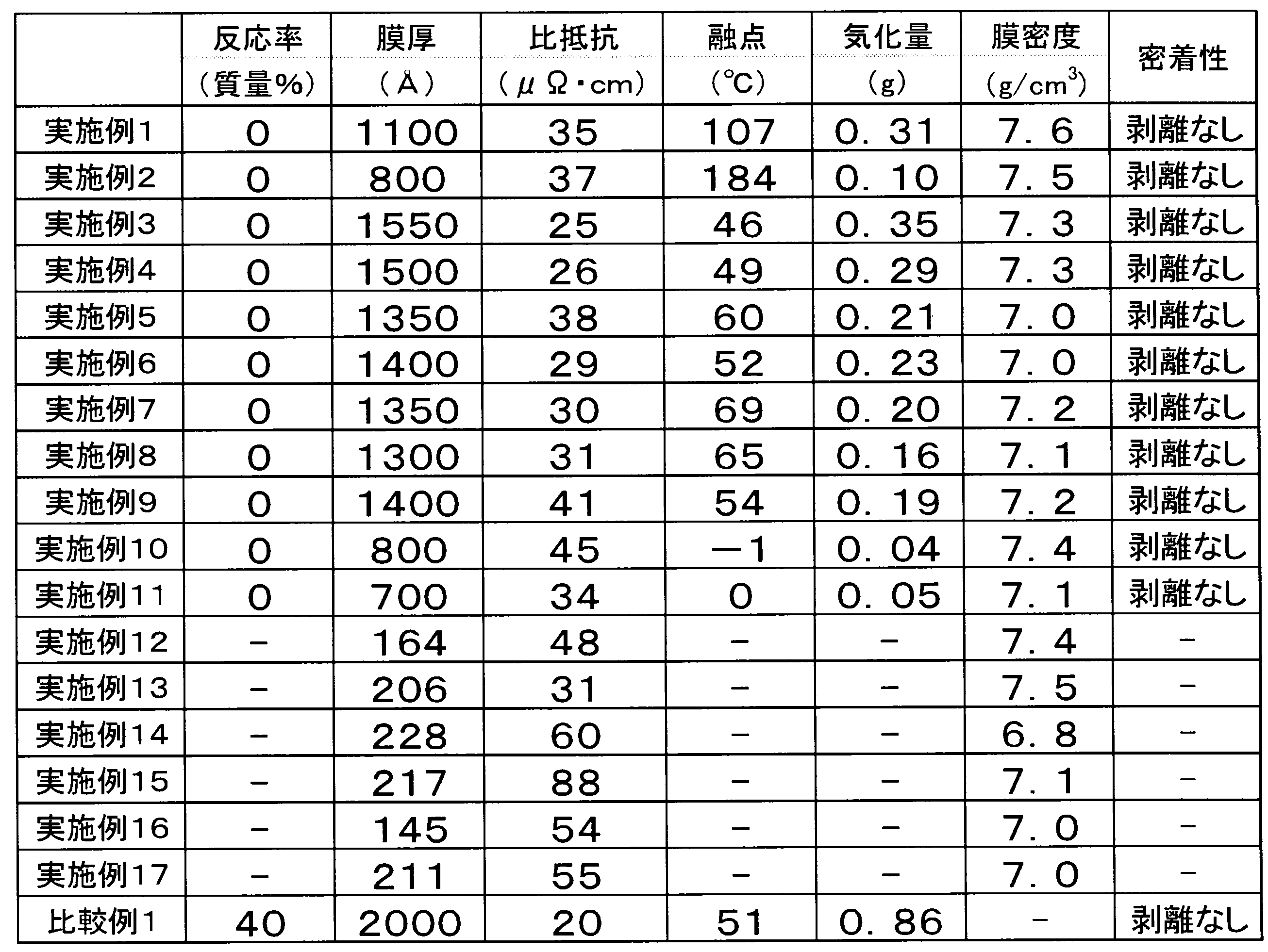
Claims (9)
- 下記式(1)で表わされる化合物を含有するコバルト膜形成用材料。
Co3(CO)9CZ ・・・(1)
(式(1)中、Zは、水素原子、ハロゲン原子、ハロゲン原子で置換されていてもよい炭素数1~10の炭化水素基、ハロゲン原子で置換されていてもよい炭素数1~10のアルコキシ基、ハロゲン原子で置換されていてもよい炭素数2~10のアシル基、ハロゲン原子で置換されていてもよい炭素数1~10のアルキルアミド基、ハロゲン原子で置換されていてもよい炭素数2~10のアルコキシカルボニル基、ハロゲン原子で置換されていてもよい炭素数2~10のアルコキシアルキル基を示す。) - 上記一般式(1)中、Zが水素原子である、請求項1に記載のコバルト膜形成用材料。
- 上記一般式(1)中、Zがハロゲン原子で置換されていてもよい炭素数2~10のアルコキシカルボニル基である、請求項1に記載のコバルト膜形成用材料。
- 化学気相成長法用である、請求項1~3のいずれか1項に記載のコバルト膜形成用材料。
- 請求項1~4のいずれか1項に記載のコバルト膜形成用材料を用いる、コバルト膜形成方法。
- 請求項1~4のいずれかに記載のコバルト膜形成用材料を基体上に供給するコバルト膜形成用材料供給工程と、該基体上に供給されたコバルト膜形成用材料を加熱分解して、上記基体上にコバルト膜を形成させる膜形成工程とを含む、コバルト膜形成方法。
- 上記膜形成工程における加熱分解の温度が100℃~800℃である、請求項6に記載のコバルト膜形成方法。
- 上記膜形成工程における加熱分解を不活性気体または還元性気体中で行う、請求項6又は7に記載のコバルト膜形成方法。
- 請求項1~3のいずれか1項に記載のコバルト膜形成用材料を、基体上に塗布し、次いで熱処理及び/又は光処理して、上記基体上にコバルト膜を形成させる膜形成工程を含む、コバルト膜形成方法。
Priority Applications (1)
| Application Number | Priority Date | Filing Date | Title |
|---|---|---|---|
| JP2011541879A JP5729307B2 (ja) | 2009-11-19 | 2010-11-05 | コバルト膜形成用材料及びコバルト膜形成方法 |
Applications Claiming Priority (4)
| Application Number | Priority Date | Filing Date | Title |
|---|---|---|---|
| JP2009264399 | 2009-11-19 | ||
| JP2009-264399 | 2009-11-19 | ||
| JP2010-081021 | 2010-03-31 | ||
| JP2010081021 | 2010-03-31 |
Publications (1)
| Publication Number | Publication Date |
|---|---|
| WO2011062069A1 true WO2011062069A1 (ja) | 2011-05-26 |
Family
ID=44059550
Family Applications (1)
| Application Number | Title | Priority Date | Filing Date |
|---|---|---|---|
| PCT/JP2010/069676 Ceased WO2011062069A1 (ja) | 2009-11-19 | 2010-11-05 | コバルト膜形成用材料及びコバルト膜形成方法 |
Country Status (3)
| Country | Link |
|---|---|
| JP (1) | JP5729307B2 (ja) |
| TW (1) | TW201126007A (ja) |
| WO (1) | WO2011062069A1 (ja) |
Cited By (1)
| Publication number | Priority date | Publication date | Assignee | Title |
|---|---|---|---|---|
| JP2013189696A (ja) * | 2012-03-15 | 2013-09-26 | Ube Industries Ltd | コバルト膜形成用原料及び当該原料を用いたコバルト含有薄膜の製造方法 |
Citations (2)
| Publication number | Priority date | Publication date | Assignee | Title |
|---|---|---|---|---|
| JP2006328526A (ja) * | 2005-04-27 | 2006-12-07 | Jsr Corp | 金属膜の形成方法 |
| JP2010150656A (ja) * | 2008-11-28 | 2010-07-08 | Jsr Corp | コバルトカルボニル錯体組成物及びコバルト膜の形成方法 |
-
2010
- 2010-11-05 WO PCT/JP2010/069676 patent/WO2011062069A1/ja not_active Ceased
- 2010-11-05 JP JP2011541879A patent/JP5729307B2/ja active Active
- 2010-11-18 TW TW099139784A patent/TW201126007A/zh unknown
Patent Citations (2)
| Publication number | Priority date | Publication date | Assignee | Title |
|---|---|---|---|---|
| JP2006328526A (ja) * | 2005-04-27 | 2006-12-07 | Jsr Corp | 金属膜の形成方法 |
| JP2010150656A (ja) * | 2008-11-28 | 2010-07-08 | Jsr Corp | コバルトカルボニル錯体組成物及びコバルト膜の形成方法 |
Non-Patent Citations (2)
| Title |
|---|
| BRIAN F.G.JOHNSON ET AL.: "Polyacrylate Resins bearing the Transition Metal Cluster Unit Co3(CO)9C", JOURNAL OF THE CHEMICAL SOCIETY, CHEMICAL COMMUNICATIONS, October 1995 (1995-10-01), pages 2117 - 2118 * |
| SAM W.-K. CHOI ET AL.: "Cobalt-Palladium and Cobalt-Platinum Bilayer Films Formed by Chemical Vapor Deposition", CHEMISTRY OF MATERIALS, vol. 9, no. 5, May 1997 (1997-05-01), pages 1191 - 1195 * |
Cited By (1)
| Publication number | Priority date | Publication date | Assignee | Title |
|---|---|---|---|---|
| JP2013189696A (ja) * | 2012-03-15 | 2013-09-26 | Ube Industries Ltd | コバルト膜形成用原料及び当該原料を用いたコバルト含有薄膜の製造方法 |
Also Published As
| Publication number | Publication date |
|---|---|
| JP5729307B2 (ja) | 2015-06-03 |
| JPWO2011062069A1 (ja) | 2013-04-04 |
| TW201126007A (en) | 2011-08-01 |
Similar Documents
| Publication | Publication Date | Title |
|---|---|---|
| CN101124676A (zh) | 材料在半导体基片上的超临界流体辅助沉积 | |
| KR20240110525A (ko) | 원자층 퇴적을 위한 유기 반응물들 | |
| TW434690B (en) | Methods for preparing ruthenium oxide films | |
| JP2002523907A (ja) | 金属ルテニウムフィルムの調製方法 | |
| JP2003526009A (ja) | ルテニウム金属膜の調製方法 | |
| JP5729307B2 (ja) | コバルト膜形成用材料及びコバルト膜形成方法 | |
| JP5754377B2 (ja) | ルテニウム膜形成方法 | |
| JP5741443B2 (ja) | ルテニウム膜形成用材料及びルテニウム膜形成方法 | |
| US8742153B2 (en) | Ruthenium complex mixture, method of producing the same, composition for film formation, ruthenium-containing film, and method of producing the same | |
| JP2010150656A (ja) | コバルトカルボニル錯体組成物及びコバルト膜の形成方法 | |
| JP2012056860A (ja) | 金属化合物及び薄膜形成用原料 | |
| JP5343483B2 (ja) | 化学気相成長材料および化学気相成長方法 | |
| JP5343482B2 (ja) | 化学気相成長方法 | |
| JP2000239843A (ja) | 金属薄膜の製造方法 | |
| JP2012111696A (ja) | ルテニウム錯体混合物、成膜用組成物、ルテニウム含有膜及びその製造方法 | |
| JP7478731B2 (ja) | 有機マンガン化合物からなる化学蒸着用原料及び該化学蒸着用原料を用いた化学蒸着法 | |
| JP5158313B2 (ja) | 銅薄膜形成材料および銅薄膜形成方法 | |
| KR101526633B1 (ko) | 디루테늄 착체 및 화학 기상 성장의 재료 및 방법 | |
| JP2003166058A (ja) | 化学気相成長用銅原料及びこれを用いた薄膜の製造方法 | |
| JPWO2011099467A1 (ja) | ルテニウム膜形成用材料及びルテニウム膜形成方法 | |
| TW200905725A (en) | Methods for forming a ruthenium-based film on a substrate | |
| Si | I4 PCl I |
Legal Events
| Date | Code | Title | Description |
|---|---|---|---|
| 121 | Ep: the epo has been informed by wipo that ep was designated in this application |
Ref document number: 10831464 Country of ref document: EP Kind code of ref document: A1 |
|
| WWE | Wipo information: entry into national phase |
Ref document number: 2011541879 Country of ref document: JP |
|
| NENP | Non-entry into the national phase |
Ref country code: DE |
|
| 122 | Ep: pct application non-entry in european phase |
Ref document number: 10831464 Country of ref document: EP Kind code of ref document: A1 |