WO2011046028A1 - Insertion device, training device, and recording system - Google Patents
Insertion device, training device, and recording system Download PDFInfo
- Publication number
- WO2011046028A1 WO2011046028A1 PCT/JP2010/067242 JP2010067242W WO2011046028A1 WO 2011046028 A1 WO2011046028 A1 WO 2011046028A1 JP 2010067242 W JP2010067242 W JP 2010067242W WO 2011046028 A1 WO2011046028 A1 WO 2011046028A1
- Authority
- WO
- WIPO (PCT)
- Prior art keywords
- delivery wire
- linear body
- force
- medical linear
- acting
- Prior art date
Links
Images


Classifications
-
- A—HUMAN NECESSITIES
- A61—MEDICAL OR VETERINARY SCIENCE; HYGIENE
- A61B—DIAGNOSIS; SURGERY; IDENTIFICATION
- A61B17/00—Surgical instruments, devices or methods, e.g. tourniquets
- A61B17/12—Surgical instruments, devices or methods, e.g. tourniquets for ligaturing or otherwise compressing tubular parts of the body, e.g. blood vessels, umbilical cord
- A61B17/12022—Occluding by internal devices, e.g. balloons or releasable wires
- A61B17/12099—Occluding by internal devices, e.g. balloons or releasable wires characterised by the location of the occluder
- A61B17/12109—Occluding by internal devices, e.g. balloons or releasable wires characterised by the location of the occluder in a blood vessel
- A61B17/12113—Occluding by internal devices, e.g. balloons or releasable wires characterised by the location of the occluder in a blood vessel within an aneurysm
-
- A—HUMAN NECESSITIES
- A61—MEDICAL OR VETERINARY SCIENCE; HYGIENE
- A61B—DIAGNOSIS; SURGERY; IDENTIFICATION
- A61B17/00—Surgical instruments, devices or methods, e.g. tourniquets
- A61B17/12—Surgical instruments, devices or methods, e.g. tourniquets for ligaturing or otherwise compressing tubular parts of the body, e.g. blood vessels, umbilical cord
- A61B17/12022—Occluding by internal devices, e.g. balloons or releasable wires
- A61B17/12131—Occluding by internal devices, e.g. balloons or releasable wires characterised by the type of occluding device
- A61B17/1214—Coils or wires
-
- A—HUMAN NECESSITIES
- A61—MEDICAL OR VETERINARY SCIENCE; HYGIENE
- A61B—DIAGNOSIS; SURGERY; IDENTIFICATION
- A61B34/00—Computer-aided surgery; Manipulators or robots specially adapted for use in surgery
- A61B34/70—Manipulators specially adapted for use in surgery
-
- A—HUMAN NECESSITIES
- A61—MEDICAL OR VETERINARY SCIENCE; HYGIENE
- A61M—DEVICES FOR INTRODUCING MEDIA INTO, OR ONTO, THE BODY; DEVICES FOR TRANSDUCING BODY MEDIA OR FOR TAKING MEDIA FROM THE BODY; DEVICES FOR PRODUCING OR ENDING SLEEP OR STUPOR
- A61M25/00—Catheters; Hollow probes
- A61M25/01—Introducing, guiding, advancing, emplacing or holding catheters
- A61M25/0105—Steering means as part of the catheter or advancing means; Markers for positioning
- A61M25/0113—Mechanical advancing means, e.g. catheter dispensers
-
- G—PHYSICS
- G01—MEASURING; TESTING
- G01L—MEASURING FORCE, STRESS, TORQUE, WORK, MECHANICAL POWER, MECHANICAL EFFICIENCY, OR FLUID PRESSURE
- G01L1/00—Measuring force or stress, in general
- G01L1/04—Measuring force or stress, in general by measuring elastic deformation of gauges, e.g. of springs
-
- G—PHYSICS
- G01—MEASURING; TESTING
- G01L—MEASURING FORCE, STRESS, TORQUE, WORK, MECHANICAL POWER, MECHANICAL EFFICIENCY, OR FLUID PRESSURE
- G01L5/00—Apparatus for, or methods of, measuring force, work, mechanical power, or torque, specially adapted for specific purposes
- G01L5/04—Apparatus for, or methods of, measuring force, work, mechanical power, or torque, specially adapted for specific purposes for measuring tension in flexible members, e.g. ropes, cables, wires, threads, belts or bands
- G01L5/10—Apparatus for, or methods of, measuring force, work, mechanical power, or torque, specially adapted for specific purposes for measuring tension in flexible members, e.g. ropes, cables, wires, threads, belts or bands using electrical means
- G01L5/101—Apparatus for, or methods of, measuring force, work, mechanical power, or torque, specially adapted for specific purposes for measuring tension in flexible members, e.g. ropes, cables, wires, threads, belts or bands using electrical means using sensors inserted into the flexible member
-
- G—PHYSICS
- G01—MEASURING; TESTING
- G01L—MEASURING FORCE, STRESS, TORQUE, WORK, MECHANICAL POWER, MECHANICAL EFFICIENCY, OR FLUID PRESSURE
- G01L5/00—Apparatus for, or methods of, measuring force, work, mechanical power, or torque, specially adapted for specific purposes
- G01L5/04—Apparatus for, or methods of, measuring force, work, mechanical power, or torque, specially adapted for specific purposes for measuring tension in flexible members, e.g. ropes, cables, wires, threads, belts or bands
- G01L5/10—Apparatus for, or methods of, measuring force, work, mechanical power, or torque, specially adapted for specific purposes for measuring tension in flexible members, e.g. ropes, cables, wires, threads, belts or bands using electrical means
- G01L5/105—Apparatus for, or methods of, measuring force, work, mechanical power, or torque, specially adapted for specific purposes for measuring tension in flexible members, e.g. ropes, cables, wires, threads, belts or bands using electrical means using electro-optical means
-
- G—PHYSICS
- G09—EDUCATION; CRYPTOGRAPHY; DISPLAY; ADVERTISING; SEALS
- G09B—EDUCATIONAL OR DEMONSTRATION APPLIANCES; APPLIANCES FOR TEACHING, OR COMMUNICATING WITH, THE BLIND, DEAF OR MUTE; MODELS; PLANETARIA; GLOBES; MAPS; DIAGRAMS
- G09B23/00—Models for scientific, medical, or mathematical purposes, e.g. full-sized devices for demonstration purposes
- G09B23/28—Models for scientific, medical, or mathematical purposes, e.g. full-sized devices for demonstration purposes for medicine
- G09B23/285—Models for scientific, medical, or mathematical purposes, e.g. full-sized devices for demonstration purposes for medicine for injections, endoscopy, bronchoscopy, sigmoidscopy, insertion of contraceptive devices or enemas
-
- A—HUMAN NECESSITIES
- A61—MEDICAL OR VETERINARY SCIENCE; HYGIENE
- A61B—DIAGNOSIS; SURGERY; IDENTIFICATION
- A61B17/00—Surgical instruments, devices or methods, e.g. tourniquets
- A61B17/00234—Surgical instruments, devices or methods, e.g. tourniquets for minimally invasive surgery
- A61B2017/00292—Surgical instruments, devices or methods, e.g. tourniquets for minimally invasive surgery mounted on or guided by flexible, e.g. catheter-like, means
- A61B2017/0034—Surgical instruments, devices or methods, e.g. tourniquets for minimally invasive surgery mounted on or guided by flexible, e.g. catheter-like, means adapted to be inserted through a working channel of an endoscope
-
- A—HUMAN NECESSITIES
- A61—MEDICAL OR VETERINARY SCIENCE; HYGIENE
- A61B—DIAGNOSIS; SURGERY; IDENTIFICATION
- A61B17/00—Surgical instruments, devices or methods, e.g. tourniquets
- A61B17/12—Surgical instruments, devices or methods, e.g. tourniquets for ligaturing or otherwise compressing tubular parts of the body, e.g. blood vessels, umbilical cord
- A61B17/12022—Occluding by internal devices, e.g. balloons or releasable wires
- A61B2017/1205—Introduction devices
-
- A—HUMAN NECESSITIES
- A61—MEDICAL OR VETERINARY SCIENCE; HYGIENE
- A61B—DIAGNOSIS; SURGERY; IDENTIFICATION
- A61B34/00—Computer-aided surgery; Manipulators or robots specially adapted for use in surgery
- A61B34/30—Surgical robots
- A61B2034/301—Surgical robots for introducing or steering flexible instruments inserted into the body, e.g. catheters or endoscopes
-
- A—HUMAN NECESSITIES
- A61—MEDICAL OR VETERINARY SCIENCE; HYGIENE
- A61B—DIAGNOSIS; SURGERY; IDENTIFICATION
- A61B90/00—Instruments, implements or accessories specially adapted for surgery or diagnosis and not covered by any of the groups A61B1/00 - A61B50/00, e.g. for luxation treatment or for protecting wound edges
- A61B90/06—Measuring instruments not otherwise provided for
- A61B2090/064—Measuring instruments not otherwise provided for for measuring force, pressure or mechanical tension
Definitions
- the present invention relates to an insertion device, a training device and a recording system, and more particularly to an insertion device, a training device and a recording system for inserting a medical linear body into a pipe in the body.
- Flexible linear bodies have been put to practical use as linear medical devices to be inserted into tubes in the body.
- a guide wire or a catheter inserted into a vessel in the body such as a blood vessel, ureter, bronchus, digestive tract or lymph vessel, or a wire with an embolic coil for embolization of an aneurysm is known. It is done.
- These linear bodies are inserted into a vessel in the body and guided to the target site by manipulation from outside the body.
- the tube into which the linear body is inserted is not necessarily linear, but is often partially bent and branched. Further, the diameter of the tube is not always constant, and the tube itself may be thin or the diameter of the tube may be reduced due to an obstacle inside the tube such as a thrombus generated in the blood vessel.
- the conventional linear body there is no means for detecting the situation in the forward direction of the linear body, and the operation of the linear body can not but rely on the operator's intuition, and is skilled in guiding operation from outside the body was necessary.
- Patent Document 1 Japanese Patent Application Laid-Open No. 10-263089
- an apparatus for providing a pressure sensor at the end of a linear body is difficult to realize, particularly for a very thin linear body.
- a guide wire to be inserted into a cerebral blood vessel its diameter is about 0.35 mm, and it is difficult to provide a small pressure sensor at the tip of such a very thin linear body.
- inserting a wiring in a linear body requires the further difficulty.
- the output of the pressure sensor provided at the tip of the linear body may not necessarily coincide with the force sense at the time of insertion of the operator. Therefore, even in the case of using a device in which a pressure sensor is provided at the tip of a linear body, based on the force sense information of the insertion resistance of the linear body gripped by the operator with a fingertip outside, that is, relying on the operator's intuition , To operate the linear body. Moreover, since only the operator can know the force sense of the operator, it is difficult to quantify the skill of the skilled operator and transfer it to the less experienced operator.
- Patent Document 2 Japanese Patent Application Laid-Open No. 2007-292711 discloses the following configuration as a technique for solving such problems. That is, a measuring device for measuring a compressive force in the longitudinal direction acting on a flexible linear body, the linear body includes a main body in which a through hole through which the linear body penetrates is formed. When the compressive force acts, the linear body curves in a predetermined direction inside the through hole, and further, a sensor that detects the degree of the curve, the detected degree of curvature, the linear body And converting the compression force acting on the
- Patent Documents 1 and 2 measure the compressive force acting on the linear body.
- Patent Document 3 Japanese Patent Application Laid-Open No. 2002-90239 discloses the following configuration. That is, in the linear body tension detection device for detecting a tensile force acting on the linear body, the support allows movement of the linear body and can be freely attached to and detached from an intermediate position of the linear body.
- a mounting portion provided at both ends of the support, a bending portion provided at a central portion of the mounting portion and extending in a direction orthogonal to the linear body to bend the linear body, and the bending portion And a detector that detects a force applied from the bent linear body when the linear body tries to return linearly, and a tensile force is detected from the force detected by the detector.
- Treatment using a catheter includes, for example, coil embolization treatment.
- the coil embolization treatment is a treatment that places a coil in the cerebral aneurysm and embolizes it, and prevents the rupture of the cerebral aneurysm which is the cause of the subarachnoid hemorrhage.
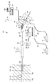
- FIG. 29 is a schematic view showing a medical device used for coil embolization treatment.
- a platinum coil 101 for coiling the cerebral aneurysm 133 is connected to the head of the delivery wire 104.
- the catheter through which the delivery wire 104 is inserted is a double tube catheter in which the parent catheter 103 is an outer tube and the child catheter 102 is an inner tube.
- the child catheter 102 is hollow, and the delivery wire 104 is inserted into the hollow portion of the child catheter 102.
- the delivery wire 104 is inserted into the Y connector 121, and the child catheter 102 is inserted into the Y connector 111.
- a doctor operates the delivery wire 104 at the grip portion 106 near the entrance of the Y connector 121.
- Another doctor operates the catheter 102 at the grip portion 105 near the entrance of the Y connector 111. That is, near the entrance of the Y connectors 111 and 121, two doctors operate the delivery wire 104 and the child catheter 102, respectively.
- the Y connectors 111 and 121 have three connection ports. One is a connection port of a catheter, the other is a port for inserting a linear body such as a catheter or a delivery wire, and the other is an input port 112, 122 for saline or medicine.
- the parent catheter 103 is inserted into the blood vessel 132 of the human body 131, and the tip thereof reaches the vicinity of the cerebral aneurysm 133.
- the child catheter 102 is inserted into the parent catheter 103 and advanced from the tip of the parent catheter 103 into the cerebral aneurysm 133.
- the coil 101 is pushed out of the child catheter 102 that has reached the inside of the cerebral aneurysm 133, and the thin and soft coil 101 is packed into the cerebral aneurysm 133. This prevents the rupture of the cerebral aneurysm 133.
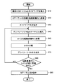
- FIG. 30 is a flow chart showing the procedure of coil embolization treatment.
- Coil embolization treatment is generally performed in the procedure shown in FIG.
- step (S10) two catheters (a parent catheter 103 and a child catheter 102) of a double tube structure and a guide wire used for guiding the catheter to a target site are placed in the artery of the thigh. insert.
- the child catheter 102 is inserted into the parent catheter 103 and the guide wire is inserted into the child catheter 102.
- step (S20) the tip of the child catheter 102 is guided by the guide wire and placed in the cerebral aneurysm 133.
- step (S30) the guide wire is withdrawn from the daughter catheter 102.
- step (S40) the delivery wire 104 attached with a platinum coil 101 at the tip is inserted into the catheter 102 instead of the guide wire.
- step (S50) the coil 101 is indwelled in the cerebral aneurysm 133.
- step (S60) an electrode is connected to the delivery wire 104, an electrode is also connected to the needle previously punctured in the human body 131, and then current is applied between the delivery wire 104 and the human body 131 via these electrodes. Flow. Since the coil 101 and the delivery wire 104 are connected by the material to be electrolyzed, the coil 101 and the delivery wire 104 are separated by energization, and as a result, the coil 101 is placed in the cerebral aneurysm 133.
- step (S70) the delivery wire 104 is withdrawn from the daughter catheter 102. Thereafter, in step (S80), it is determined whether the coil 101 has been densely packed in the cerebral aneurysm 133 or not. If it is determined that the cerebral aneurysm 133 is not densely filled with the coil 101, the process returns to the step (S40), and the delivery wire 104 with another coil 101 is inserted into the child catheter 102. Steps (S40) to (S70) are repeated until the coil 101 is tightly packed in the cerebral aneurysm 133.
- step (S90) If it is determined that the inside of the cerebral aneurysm 133 is densely filled by the coil 101, then in step (S90), the parent catheter 103 and the child catheter 102 are withdrawn from the human body 131. Thus, the coil embolization treatment of the cerebral aneurysm 133 is completed.
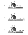
- FIG. 31 is a schematic view showing a catheter operation when placing a coil in a cerebral aneurysm.
- FIG. 31 (a) when the coil 101 connected to the tip of the delivery wire 104 is placed in the cerebral aneurysm 133 to embolize the cerebral aneurysm 133, the coil 101 is inserted inside the cerebral aneurysm 133.
- the uneven distribution may increase the density of the coil 101 near the tip of the child catheter 102.
- the distal end portion of the secondary catheter 102 is in the large coil density region 134, the insertion resistance of the coil 101 into the cerebral aneurysm 133 is increased.
- the delivery wire 104 is further inserted into the blood vessel 132 in a state where the insertion resistance is high, the cerebral aneurysm 133 which is thin and fragile in the blood vessel wall may be ruptured. Therefore, when sensing that the insertion resistance of the coil 101 is large, the doctor operating the delivery wire 104 suspends the insertion of the delivery wire 104.
- the doctor operating the child catheter 102 retracts the child catheter 102. That is, as shown in FIG. 31 (b), the doctor operating the child catheter 102 moves the child catheter 102 in the DR1 direction to withdraw from the blood vessel 132. Thereafter, the doctor operating the child catheter 102 advances the child catheter 102 again. That is, the doctor operating the child catheter 102 moves the child catheter 102 in the DR2 direction to be inserted into the blood vessel 132, as shown in FIG. 31 (c).
- the operation of temporarily retracting the child catheter 102 and advancing it again changes the position of the tip of the child catheter 102, and the tip of the child catheter 102 moves into the small coil density region 135 in the cerebral aneurysm 133.
- the insertion resistance of the coil 101 into the cerebral aneurysm 133 decreases.
- the doctor operating the delivery wire 104 resumes the insertion of the delivery wire 104, that is, the insertion of the coil 101 into the cerebral aneurysm 133.
- catheter treatment requires the skill of the operator because delicate control of the operation of the catheters 102 and 103 and the delivery wire 104 is required. Therefore, in order to improve the operability of the catheters 102 and 103 and the delivery wire 104 in catheter treatment, several master-slave drive devices have been proposed (for example, Japanese Patent Laid-Open No. 2000-42116). And Patent Document 5 (Japanese Patent Application Laid-Open No. 2001-157662).
- the measurement of the compressive force acting on the linear body is a function necessary to prevent the human body from being damaged by applying an excessive compressive force or insertion force to the linear body introduced into the body.
- the required operation is different from the case of manually operating the linear body such as the delivery wire 104 and the catheters 102 and 103. Therefore, new training of the surgeon is required.
- a master-slave device it is difficult to sense minute changes in the patient's pulse or blood vessel 132 and the like. Therefore, it is preferable for the operator to grip the linear body and manipulate the linear body manually.
- the scale function changes the ratio of the movement amount of the linear body on the slave side to the operation amount on the master side when performing a fine operation, and makes it a scale that is easy for humans to handle. Assuming that the scale value is N times, the movement amount on the slave side is 1 / N times the reciprocal of the scale value with respect to the operation on the master side. At this time, the length of the operation part of the linear body on the master side Is N times the movement amount of the linear body on the slave side.
- the present invention has been made in view of the above problems, and its main object is to apply an excessive compressive force (insertion force) and tensile force (extraction force) to a medical linear body with a simple configuration.
- insertion force insertion force
- tensile force extraction force
- an insertion device for inserting a medical linear body into a pipe in a body, and a drive for moving the medical linear body in the longitudinal axis direction
- the device includes a measuring device that measures a compressive force and a tensile force in the longitudinal direction acting on the medical linear body, and a notification device that notifies the operator of the compressive force and the tensile force measured by the measuring device.
- controlling the drive device when the compressive force measured by the measuring device exceeds the first threshold or when the tensile force measured by the measuring device exceeds the second threshold to reduce the moving speed of the medical linear body or stop the movement of the medical linear body according to the amount by which the compressive force and the tensile force respectively exceed the first and second threshold values.
- it further comprises a Y connector for inserting the medical linear body into the catheter.
- the drive device is disposed on the insertion port side of the medical linear body in the Y connector, and is detachable from the Y connector.
- the medical linear body is a delivery wire provided with an embolic coil at its tip.
- a foot switch is provided for starting and stopping movement of the medical linear body by the drive device in response to the operation of the operator.
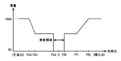
- the notification device reports the compression force and the tension force acting on the medical linear body to the operator by light or sound, and according to the magnitude of the compression force and the tension force measured by the measurement device, Change the brightness of light, the wavelength of light, the frequency of light, the number of intermittently generated light per predetermined time, the volume, the wavelength of sound, the frequency of sound or the number of intermittently generated sound per predetermined time .
- the measuring device includes a main body in which a through hole for inserting the medical linear body is formed.
- the through hole is formed so that the medical linear body is curved in an arc shape inside the through hole, and the degree of curvature of the medical linear body is changed according to the compression force and the tensile force.
- the measuring device further includes a sensor for detecting the degree of curvature of the medical linear body, and a conversion circuit for converting the degree of curvature detected by the sensor into a signal indicating compressive force and tensile force acting on the medical linear body. And.
- the conversion circuit is detected when the degree of bending of the medical linear body is increased as compared to the degree of curvature of the medical linear body when no compressive force or tensile force is acting on the medical linear body.
- the degree of curvature is converted into a signal indicating the compressive force acting on the medical linear body, and compared to the degree of curvature of the medical linear body when no compressive force or tensile force is acting on the medical linear body.
- the degree of curvature of the medical linear body decreases, the detected degree of curvature is converted into a signal indicating a tensile force acting on the medical linear body.
- the apparatus further comprises a Y-connector for inserting the medical linear body into the catheter, and the measuring device is integrated with the Y-connector.
- the senor includes a light receiver for receiving the light emitted by the light source, and the medical linear body intercepts the light emitted by the light source to detect the position where the amount of light received by the light receiver is reduced. It is an optical line sensor for detecting the degree of curvature of a linear object.
- the connector further comprises a Y connector for inserting the medical linear body into the catheter, and the Y connector is detachable from the line sensor.
- the line sensor and the drive unit are integrated via a base.
- the drive device includes a rotational force generator, a drive roller rotationally driven by the rotational force generated by the rotational force generator, a driven roller rotated following the rotation of the drive roller, and a rotational force generator And a case including a driving roller and a driven roller, and an elastic body provided between the case and the driven roller.
- the medical linear body is held between the rotational surface of the drive roller and the rotational surface of the driven roller, and the driven roller is supported by the case via the elastic body, and is pressed against the drive roller by the elastic force of the elastic body. The pressure on the driven roller against the drive roller can be manually released.
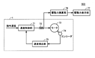
- the drive device includes a rotational force generator for generating a rotational force for moving the medical linear body in the longitudinal axis direction based on the supplied drive current, and a current detector for detecting the drive current. And. The measuring device measures the compressive force and the tensile force acting on the medical linear body based on the drive current detected by the current detector.
- a linear body velocity commanding unit is further provided which controls the moving speed of the medical linear body by the drive device in response to the operation of the operator.
- the training device concerning the first aspect of the present invention is provided with the above-mentioned insertion device.
- a recording system includes an insertion device for inserting a medical linear body into a pipe in a body, and a recording device, and the insertion device is a medical linear body Drive device for moving the longitudinal axis direction, a measuring device for measuring the compressive force and tensile force in the longitudinal direction acting on the medical linear body, and the operator using the compressive force and the tensile force measured by the measuring device And a notification device to be notified.
- the recording device temporally correlates and records an image obtained by photographing the medical linear body, and a compression force and a tensile force measured by the measurement device.
- the recording device temporally correlates and records the image, the compressive force and the tensile force, and the moving speed of the medical linear body by the drive device.
- FIG. 3 is a partial cross-sectional schematic view of the drive device along the line III-III shown in FIG. 2;
- FIG. 4 is a schematic cross-sectional view of the drive device taken along line IV-IV shown in FIG. 2;
- FIG. 5 is a side view of the drive shown in FIGS. 2 to 4; It is an outline view showing composition of a main part of a measuring device concerning a 1st embodiment of the present invention.
- FIG. 7 is a cross sectional view taken along the line VII-VII in FIG.
- FIG. 8 is a view showing a state in which a compressive force acts on the delivery wire 104 and the delivery wire 104 is bent inside the main body 52 in the cross-sectional view of FIG. 7.
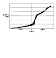
- FIG. 8 is a view showing a state in which a tensile force is applied to the delivery wire 104 and the delivery wire 104 is bent inside the main body 52 in the cross-sectional view of FIG. 7. It is a figure which shows correlation with the force which acts on a linear body, and the position of the linear body detected by the line sensor.
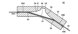
- FIG. 20 is a cross sectional view taken along the line XX-XX of FIG. 19;
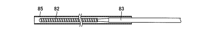
- FIG. 20 is a view showing a state in which a sheath 85 is inserted into the main body 52 in the cross-sectional view of FIG.
- FIG. 20 is a figure which shows the structure of the insertion apparatus which concerns on the 3rd Embodiment of this invention.
- each component is not necessarily essential to the present invention, unless otherwise specified. Further, in the following embodiments, when referring to the number, the amount and the like, the number and the like are exemplification unless otherwise specified, and the scope of the present invention is not necessarily limited to the number, the amount and the like.
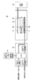
- FIG. 1 is a schematic view showing a configuration of an insertion device for inserting a delivery wire into a blood vessel according to a first embodiment of the present invention.
- an insertion device for inserting the delivery wire 104 inserted into the catheters 102 and 103 into the blood vessel 132 in the body, which is used for coil embolization treatment, will be described.
- the delivery wire 104 as a medical linear body is inserted into the Y connector 31.
- a platinum coil 101 for coil embolization of the cerebral aneurysm 133 is connected.
- the delivery wire 104 is inserted from the first input port 32 into the Y connector 31, penetrates the Y connector 31, and is inserted into the child catheter 102 connected to the output port 34.
- the configuration of the insertion device from the output port 34 of the Y connector 31 to the inside of the human body 131 is the same as that of the conventional medical instrument 100 shown in FIG. 29, so the description will not be repeated.
- the insertion device 501 includes the drive device 1 that moves the delivery wire 104 in the longitudinal direction.
- the driving device 1 is disposed on the insertion port side of the delivery wire 104 in the Y connector 31 and is detachable from the Y connector 31.
- the driving device 1 includes a driving roller 5 and a driven roller 6.
- the delivery wire 104 is nipped by the rotational surface of the drive roller 5 and the rotational surface of the driven roller 6, and moves in the longitudinal axis direction in response to the rotation of the drive roller 5.
- the longitudinal movement of the delivery wire 104 by the drive device 1 is controlled by the drive control device 40.
- An insertion foot switch 41 is electrically connected to the drive control device 40 by a wire 42, and a pulling foot switch 46 is electrically connected by a wire 47.
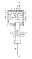
- FIG. 2 is a schematic cross-sectional view of a drive device for a linear medical object.
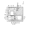
- FIG. 3 is a schematic partial cross-sectional view of the drive device taken along line III-III shown in FIG.
- FIG. 4 is a schematic cross-sectional view of the drive device taken along line IV-IV shown in FIG.
- FIG. 5 is a side view of the drive shown in FIGS.
- the configuration of the drive device 1 of the medical linear body (delivery wire 104) will be described with reference to FIGS.
- FIG. 2 is a cross-sectional view of the drive device taken along line II-II shown in FIG.
- the drive device 1 includes a housing 2.
- the housing 2 has a lid member 10 provided so as to be openable and closable by rotational movement with a hinge 11 as a pivot.
- a partition 16 is provided in an internal space of the drive device 1 formed so as to be surrounded by the housing 2 and the lid member 10.
- the partition 16 divides the internal space of the drive device 1 into a large space 2a which is a first space and a small space 2b which is a second space.
- a motor 3 as a rotational force generator and a reduction gear 9 for reducing and outputting the rotational speed of the rotational force generated by the motor 3 are disposed.
- the motor 3 is a motor that converts electrical energy into mechanical energy.
- the partition 16 is formed with a hole 16 a penetrating the partition 16 in the thickness direction.
- the rotation shaft 4 as a rotation part is arrange
- the rotating shaft 4 transmits to the driving roller 5 the rotational force generated by the motor 3 and reduced in rotational speed by the reduction gear 9.
- the case forming the outer shell of the small chamber 2 b is formed by a part of the housing 2 and the partition wall 16.
- a portion of the housing 2 and the partition wall 16 form a wall portion of a case that encloses the motor 3 and the reduction gear 9.
- the case is formed in a rectangular box shape
- the partition 16 forms one surface of the wall of the case
- the housing 2 forms three surfaces of the bottom, ceiling and wall of the case Do.
- a hole 16a through which the rotating shaft 4 passes is formed in the partition wall 16 which constitutes a part of the case.
- a seal portion 19 is provided on the inner peripheral surface of the hole portion 16 a formed in the partition wall 16.
- the seal portion 19 is formed to be in contact with the inner peripheral surface of the hole 16 a and to be in contact with the outer peripheral surface of the rotary shaft 4.
- the seal portion 19 closes the gap between the partition wall 16 and the rotary shaft 4 to shut off the small chamber 2 b inside the case from the outside.
- the small chamber 2b in which the motor 3 and the reduction gear 9 are disposed communicates with the large chamber 2a only through the hole 16a, but since the hole 16a is closed by the seal portion 19, the large chamber 2a And the compartment 2b are separate spaces.
- the small space 2 b is made into a sealed space by the sealing portion 19 closing the hole portion 16 a.
- the seal portion 19 suppresses the leakage of the liquid from the large chamber 2a to the small chamber 2b via the hole 16a.
- a drive roller 5 which performs rotational movement by the rotational force generated by the motor 3 and transmitted with the rotational shaft 4 interposed.
- the driving roller 5 is a feed roller attached to the motor 3 with the rotating shaft 4 and the reduction gear 9 interposed, and is formed in a substantially cylindrical shape.
- the reduction gear 9 is interposed between the motor 3 and the drive roller 5.
- the rotating shaft 4 transmits a rotational force from the reduction gear 9 to the drive roller 5.
- a feed groove 5 b is formed on the rotational surface 5 a which is a cylindrical side surface of the drive roller 5.
- the feed groove 5b has a V-shape or a suitable curvature.
- a driven roller 6 is disposed in the large chamber 2 a so as to face the rotational surface 5 a of the drive roller 5.
- the driven roller 6 which is a pressing roller that applies pressure to the delivery wire 104 is formed in a substantially cylindrical shape.
- the delivery wire 104 is held between the rotational surface 6 a of the driven roller 6 which is the side surface of the cylindrical shape and the rotational surface 5 a of the drive roller 5.
- the rotational surface 5 a of the drive roller 5 and the rotational surface 6 a of the driven roller 6 are positioned to face each other with the delivery wire 104 interposed.
- the delivery wire 104 is disposed between the rotation surfaces 5 a and 6 a so as to be along the feed groove 5 b formed on the rotation surface 5 a of the drive roller 5.
- the driven roller 6 When the motor 3 is activated and the drive roller 5 performs rotational motion, the driven roller 6 performs rotational motion following the rotation of the drive roller 5. As the drive roller 5 and the driven roller 6 rotate in opposite directions, the delivery wire 104 moves in the longitudinal axis direction of the delivery wire 104. The delivery wire 104 is driven by the drive roller 5.
- the motor 3 for generating the rotational force, the reduction gear 9 and the rotational shaft 4 for transmitting the rotational force, and the drive roller 5 and the driven roller 6 for performing the rotational movement are feeding devices for moving the delivery wire 104 in its longitudinal axis direction Is included in the actuator.
- the actuator holds the delivery wire 104 and moves it so as to be fed in the longitudinal direction.
- the actuator is disposed in the internal space of the housing 2 and is held by the housing 2.
- the drive roller 5 When the driven roller 6 is pressed against the drive roller 5 to clamp the delivery wire 104, the drive roller 5 can be controlled so that the delivery wire 104 can be prevented from being damaged and the delivery wire 104 can be moved smoothly. It is desirable to form the rotational surface 5a of the second embodiment and the rotational surface 6a of the driven roller 6.
- stainless steel can be used as the material of the driving roller 5 and the driven roller 6, and a urethane resin or the like can be coated and used as the material of the rotating surfaces 5a and 6a.
- the surface of the delivery wire 104 is brought into surface contact with the rotation surfaces 5a and 6a, and the rotation surfaces 5a and 6a.
- the friction force generated between the and the delivery wire 104 can be increased. Due to this frictional force, when moving the delivery wire 104, even if the compressive force acting on the delivery wire 104 in the longitudinal direction increases, the delivery wire 104 is prevented from slipping against the rotation surfaces 5a and 6a. can do.
- the feed groove 5b is formed on the rotation surface 5a of the drive roller 5, the contact area between the delivery wire 104 and the rotation surface 5a is increased. The formation of the feed groove 5b can also increase the frictional force generated between the rotating surfaces 5a and 6a and the delivery wire 104.
- the rotation surface 5a of the drive roller 5 may be formed as a smooth curved surface without any groove and without a groove, and a feed groove in which a linear body is disposed may be formed in the rotation surface 6a of the driven roller 6. Further, feed grooves may be formed on both of the rotation surfaces 5a and 6a. That is, a groove is formed on at least one of the rotational surfaces 5a and 6a of the drive roller 5 and the driven roller 6, the delivery wire 104 is disposed in the groove, and the surface of the delivery wire 104 makes surface contact with the inner surface of the groove. With this configuration, it is possible to increase the frictional force by increasing the contact area between the delivery wire 104 and the rotating surfaces 5a and 6a, and to obtain the effect of suppressing the slip of the delivery wire 104.
- the driven roller 6 is supported by the lid member 10 in the large chamber 2 a of the internal space of the drive device 1 with the support member 7 rotatably supporting the driven roller 6 and the elastic body 8 interposed.
- the driven roller 6 is supported in a suspended state from the lid member 10.
- the elastic body 8 is attached to the lid member 10.
- the driven roller 6 is supported by the lid member 10 with an elastic body 8 such as rubber interposed between the driven roller 6 and the lid member 10.
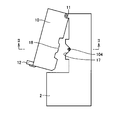
- the lid member 10 has a lever 12 for operating the opening and closing of the lid member 10.
- the lever 12 is formed so as to be elastically deformable.
- the lever 12 shown in FIG. 3 has a substantially U-shaped shape.
- the lever 12 is elastically deformable so as to narrow the U-shaped width or widen the U-shaped width.
- a projection 13 is formed on the lever 12. The lever 12 is fixed to the housing 2 by the projection 13 being locked to the locking portion 14 of the housing 2.
- the housing 2 is provided with an elastic portion 15. Further, an elastic portion 15 is provided on the lid member 10. As shown in FIG. 2, the Y connector 31 is fixed so as to be held between the elastic portion 15 on the housing 2 side and the elastic portion 15 on the lid member 10 side.
- the housing 2 holds a Y connector 31 as a medical instrument.
- a through hole is formed in the Y connector 31 so as to penetrate the inside from the first input port 32 to the output port 34.
- the delivery wire 104 is inserted into the through hole of the Y connector 31.
- the Y connector 31 is formed with another through hole which penetrates the inside from the second input port 33 to the output port 34.
- the Y connector 31 is a fixed member fixed at the fixing portion of the drive device 1.
- the fixing portion has a hole shape formed in the abutment portion between the side wall of the housing 2 and the side wall of the lid member 10, and an elastic portion 15 such as rubber provided on the inner peripheral side of the hole shape.
- the drive device 1 can fix the Y connector 31 as a fixed member at the fixing portion.
- the Y connector 31 is attached to the fixed portion by being sandwiched by the elastic portion 15 attached to the housing 2 and the lid member 10.
- the elastic portion 15 is held by the housing 2.
- the groove 17 is formed in the abutment portion between the other side wall of the housing 2 and the other side wall of the cover member 10 facing the one side wall of the housing 2 and the cover member 10 provided with the fixing portion capable of fixing the Y connector 31 .
- the guide groove 17 is formed in the other side wall of the housing 2 facing the side wall of the housing 2 in which the elastic portion 15 is provided at the abutting portion with the lid member 10.
- the guide groove 17 is formed by cutting a part of the other side wall of the housing 2.
- the protrusion 18 fits inside the guide groove 17.
- the space surrounded by the projecting portion 18 and the guide groove 17 has a diameter slightly larger than the diameter of the delivery wire 104, and the delivery wire 104 can be inserted into the space. That is, when the lid member 10 is closed and the delivery wire 104 and the Y connector 31 are integrally attached to the fixing portion of the drive device 1, the delivery wire 104 is positioned by the guide groove 17.
- the drive device 1 is provided with a guide groove 17 for passing the delivery wire 104 as a guide for positioning the delivery wire 104.
- the deepest part of the guide groove 17 where the delivery wire 104 is placed is located near the position where the extension of the through hole formed in the Y connector 31 intersects the other side wall of the housing 2 and the lid member 10 ( Typically, the extending direction of the deepest part of the guide groove 17 penetrating the other side wall of the housing 2 is formed to coincide with the extending direction of the through hole of the Y connector 31).
- the delivery wire 104 By closing the lid member 10 of the drive device 1 provided with the guide portion, the delivery wire 104 is positioned, and the delivery wire 104 is set at the correct position. That is, when the lid member 10 is closed, the delivery wire 104 is correctly installed between the driving roller 5 and the driven roller 6. Therefore, it is possible to suppress the occurrence of a defect that the movement of the delivery wire 104 is hindered or the delivery wire 104 is damaged when the delivery wire 104 is pinched by the abutting portion between the lid member 10 and the housing 2.
- the guide groove 17 may be formed in a V-shaped shape as shown in FIG. 5, or may be formed in a shape having a curved surface with an appropriate curvature such as a U-shape or an arc shape.
- the opening and closing operation of the lid member 10 of the drive device 1 From the state in which the cover member 10 shown in FIGS. 2 and 3 is closed, the lever 12 is elastically deformed so as to narrow the width of the U-shape, and the engagement between the projection 13 and the locking portion 14 is released.
- the lid member 10 is rotatable with the hinge 11 as a rotation axis.
- the lid member 10 is opened by moving the lid member 10 in the counterclockwise direction with the hinge 11 as the rotation center.
- the lid member 10 can be manually opened.
- the lever 12 is elastically deformed to release the engagement between the projection 13 and the locking portion 14, and the lid member 10 can be opened.
- the elastic portion 15 attached to the lid member 10 moves together with the lid member 10.
- the elastic force is not applied to a part of the outer periphery of the Y connector 31 held by the elastic force applied from the elastic portion 15. Therefore, the Y connector 31 can be moved manually.
- the driven roller 6 also moves together with the lid member 10.
- the pressing force applied from the rotation surface 6 a of the driven roller 6 to the rotation surface 5 a of the driving roller 5 is released, and the delivery wire 104 is not held. Therefore, the delivery wire 104 held by the pressing force is It can be moved manually. Since the lid member 10 is moved and a part of the peripheral edge of the guide groove 17 is opened, the delivery wire 104 can freely move not only in the longitudinal axis direction.
- both the Y connector 31 and the delivery wire 104 can be moved manually, the delivery wire 104 and the Y connector 31 are integrally moved while the delivery wire 104 is inserted through the through hole of the Y connector 31.
- the lid member 10 provided in the driving device 1 can open the roller portion including the driving roller 5 and the driven roller 6, the fixing portion to which the Y connector 31 is fixed, and the guide groove 17.
- the delivery wire 104 and the Y connector 31 inserted into the Y connector 31 can be integrally removed from the fixing portion for fixing the Y connector 31. Therefore, even if some abnormality such as a power failure occurs and the driving device 1 is stopped, the delivery wire 104 and the Y connector 31 can be manually removed integrally.
- the lid member 10 when the lid member 10 is rotated with the hinge 11 as the rotation axis from the state in which the lid member 10 is opened, the lid member 10 moves in the closing direction.
- the lid member 10 In the cross sectional view shown in FIG. 3, the lid member 10 is closed by moving the lid member 10 in the clockwise direction with the hinge 11 as the rotation center.
- the lid member 10 can be closed manually.
- the projection 13 of the lever 12 collides with the locking portion 14, the lever 12 is elastically deformed so that the width of the U-shape of the lever 12 becomes narrow.
- the protrusion 13 passes through the locking portion 14 such that the protrusion 13 slides on the surface of the locking portion 14.
- the lever 12 is elastically deformed so as to widen the width of the U-shape, and the protrusion 13 engages with the locking portion 14.
- the cover member 10 is pushed down toward the housing 2 side, the movement of the driven roller 6 attached to the cover member 10 and the support member 7 to the housing 2 side is supported by the motor 3 fixed to the housing 2 It is blocked by the driven drive roller 5. Therefore, the elastic body 8 sandwiched between the lid member 10 and the support member 7 is elastically deformed.
- the cover member 10 is pressed by the elastic force exerted on the cover member 10 by the elastically deformable elastic body 8 as a reaction.
- the projection 13 of the lever 12 is in close contact with the locking portion 14 and the lever 12 is pressed against the housing 2.
- the lid member 10 is closed, the lever 12 is pressed against the housing 2 by the elastic force of the elastic body 8 pressing the lid member 10.
- the lid 12 is closed by pressing the lever 12 against the housing 2 by the elastic force of the elastic body 8.
- the Y connector 31 can be assembled to the elastic portion 15 of the housing 2 with the delivery wire 104 penetrating through the through hole.
- the Y connector 31 is held by the elastic portion 15 on the housing 2 side and the elastic portion 15 on the lid member 10 side.
- the delivery wire 104 is disposed inside the guide groove 17 so as to be sandwiched by the rotational surface 5 a of the drive roller 5 and the rotational surface 6 a of the driven roller 6 and to penetrate the housing 2 in which the guide groove 17 is formed. Be done.
- the delivery wire 104 and the Y connector 31 are supported by the drive device 1 at the elastic portion 15, between the drive roller 5 of the roller portion and the driven roller 6, and at the guide groove 17.
- Opening and closing of the lid member 10 can be performed by manual operation by operating the lever 12.
- the delivery wire 104 and the Y connector 31 can be integrally removed from the fixed portion as it is, and the delivery wire 104 and the Y connector 31 are integrally attached to the fixed portion by closing the lid member 10. be able to. That is, in the drive device 1 for the delivery wire 104 according to the present embodiment, the delivery wire 104 and the Y connector 31 can be integrated and removed from the fixed portion of the drive device 1 manually.
- the delivery wire 104 and the Y connector 31 can be attached to and detached from the drive device 1 in an integrated state in which the delivery wire 104 is inserted into the through hole of the Y connector 31.
- the delivery wire 104 and the Y connector 31 do not necessarily have to be integrally attached to the drive device 1. That is, in the drive device 1 in which the guide portion is provided, the delivery wire 104 can be reliably positioned by the guide portion. Therefore, after the lid member 10 is closed and the Y connector 31 is attached to the fixing portion, the delivery wire 104 is inserted into the drive device 1 through the guide portion, whereby the delivery wire 104 is inserted into the through hole of the Y connector 31 It is also possible. As a result, there is no need to handle the delivery wire 104 and the Y connector 31 integrally at all times, and the operability of the drive device 1 can be further improved.
- the driving device 1 inserts the delivery wire 104 into the hollow portion of the child catheter 102 connected to the through hole of the Y connector 31 and inserts the delivery wire 104 into the blood vessel 132 of the human body 131 as shown in FIG. Has been applied.
- the delivery wire 104 and the Y connector 31 can be manually removed integrally.
- the positional relationship between the secondary catheter 102 and the delivery wire 104 does not change before and after removal. Therefore, the treatment can be resumed manually immediately with little change in the position of the coil 101 in the blood vessel 132 or the cerebral aneurysm 133.
- a line sensor housing 51 and a light source 81 are attached to the Y connector 31 with the delivery wire 104 interposed therebetween.
- the lens 23 and the line sensor 80 are incorporated in the line sensor housing 51.
- the medical linear body drive device 1 described above includes an actuator for moving the delivery wire 104 in the longitudinal direction.
- the actuator includes a motor 3, a reduction gear 9 that reduces the rotational speed of the rotational force generated by the motor 3 and outputs it, a drive roller 5 that performs rotational movement by the rotational force transmitted from the motor 3, and a rotation of the drive roller 5 And a driven roller 6 that performs rotational movement.
- the rotation of the drive roller 5 for driving the delivery wire 104 is performed by the motor 3, but the rotational drive force of the motor 3 is transmitted to the drive roller 5 via the reduction gear 9.
- the torque is increased in proportion to the ratio of the rotational speed between the output shaft of the motor 3 and the output shaft of the reduction gear 9, that is, the reduction ratio. It can be done.
- the torque transmitted to the drive roller 5 can be increased, and the drive force for moving the delivery wire 104 in the longitudinal direction can be increased. Therefore, since the desired driving force of the delivery wire 104 can be obtained with a small motor, the manufacturing cost of the drive device 1 can be reduced.
- the driving speed of the delivery wire 104 is several mm / s.
- the motor 3 rotatable at a number of rotations larger than the number of rotations of the drive roller 5 is used, and the number of rotations of the output shaft of the motor 3 is reduced by the reduction gear 9
- the driving force of the delivery wire 104 by the driving roller 5 can be increased.
- the motor 3 drives the delivery wire 104, even if a resistance is externally applied to the delivery wire 104 by an external load such as a frictional force, the resistance becomes an inverse number of the reduction ratio. For example, when the motor 3 is rotated at a relatively large reduction ratio of about 100 to 1000, the resistance force acting on the delivery wire 104 with respect to the rotational driving force of the motor 3 can be ignored. Therefore, the delivery wire 104 can be driven stably at a predetermined speed.
- the actuator for moving the delivery wire 104 in the longitudinal direction may be any equipment as long as it can transfer the long delivery wire 104 in the extending direction, but the electric motor described in this embodiment is used.
- the moving speed of the delivery wire 104 is determined according to the number of rotations of the motor 3. For example, in the practical range (the insertion force number N or less), the voltage applied to the motor 3 and the moving speed of the delivery wire 104 have a linear relationship. Therefore, by preparing in advance a relationship table between the voltage applied to the motor 3 and the moving speed of the delivery wire 104, the moving speed of the delivery wire 104 intended by the operator, ie, the rotational speed instructed by the drive control device 40, is prepared. At the same time, the voltage applied to the motor 3 can be changed.
- the delivery wire 104 can be moved in the longitudinal axis direction at an arbitrary moving speed only by changing the voltage applied to the motor 3. Therefore, the moving speed of the delivery wire 104 can be controlled with a simple configuration. Since the number of parts of the drive device 1 can be reduced without requiring a sensor such as an encoder for detecting the rotational speed of the drive roller 5, the manufacturing cost of the drive device 1 can be reduced, and the reliability of the drive device 1 can be reduced. It is possible to improve the quality. In this case, the acting force of the delivery wire 104 is detected by the measuring device 60 built in the Y connector 31.
- the rotary shaft 4 passes through a hole 16a communicating the inside and the outside of the small chamber 2b in which the motor 3 and the reduction gear 9 are arranged, and the inner periphery of the hole 16a is formed in the hole 16a.
- a seal 19 is provided in contact with the surface and the outer peripheral surface of the rotary shaft 4.
- the drive 1 needs to be configured.
- the seal portion 19 to isolate the inside of the small chamber 2b from the large chamber 2a, it is possible to prevent the liquid from entering the small chamber 2b from the large chamber 2a.
- the seal portion 19 disposed between the rotary shaft 4 and the partition 16 can be formed of an elastic material such as a resin material represented by silicone resin.
- the seal portion 19 Since the seal portion 19 is provided, when the rotary shaft 4 is rotated, the outer peripheral surface of the rotary shaft 4 slides in contact with the seal portion 19, and the torque necessary for the rotation of the rotary shaft 4 increases.
- the rotational force generated by the motor 3 is transmitted from the rotary shaft 4 to the drive roller 5 via the reduction gear 9, and the torque transmitted to the drive roller 5 is increased. Therefore, the frictional resistance due to the rotational shaft 4 sliding with respect to the seal portion 19 can be ignored from the motor 3. Therefore, the delivery wire 104 can be driven stably at a predetermined speed.
- the insertion device 501 includes a foot switch that starts and stops the movement of the delivery wire 104 by the drive device 1 in response to the operation of the operator.
- the foot switch generates a signal for controlling the activation and stop of the drive device 1 by the operation of stepping on the foot.
- the foot switch includes an insertion foot switch 41 and a withdrawal foot switch 46.
- the insertion foot switch 41 is connected to the drive control device 40 by a wire 42.
- the pull-out foot switch 46 is connected to the drive control device 40 by a wire 47.
- the drive device 1 By depressing the insertion foot switch 41 with a foot, the built-in micro switch is pressed, and the drive device 1 operates so as to move the delivery wire 104 in a direction to be inserted into the blood vessel 132. Specifically, the delivery wire 104 is driven in the direction in which the drive roller 5 rotates and advances, that is, the direction in which the drive roller 5 is inserted into the daughter catheter 102. Thereby, the insertion operation of inserting the coil 101 into the cerebral aneurysm 133 is performed.
- the drive device 1 By depressing the withdrawal foot switch 46 with a foot, the built-in micro switch is pressed, and the drive device 1 operates so as to move the delivery wire 104 in the direction of withdrawing the blood vessel 132. Specifically, the drive roller 5 is reversely rotated, and the delivery wire 104 is driven in the backward direction, that is, in the direction of being pulled out of the secondary catheter 102. As a result, the delivery wire 104 attached to the distal end of the coil 101 is pulled out from the blood vessel 132 and a withdrawal operation is performed.
- a doctor who performs coil embolization treatment using this insertion device holds the Y-connector 111 into which the child catheter 102 is inserted with the left hand and holds the child catheter 102 with the right hand at the holding portion 105 near the entrance of the Y connector 111. Can operate. Also, the same doctor inserts the delivery wire 104 into the child catheter 102 by operating the insertion footswitch 41 and the withdrawal footswitch 46 with the foot, and inserts the coil 101 into the cerebral aneurysm 133. Can. That is, the operation of the catheter 102 and the operation of the delivery wire 104 can be realized by one doctor.
- this insertion device by using this insertion device, one doctor can perform coil embolization treatment that places the coil 101 in the cerebral aneurysm 133 and embolizes the cerebral aneurysm 133. There is no need for two doctors to work together in order to be able to perform coil embolization treatment conventionally performed by two doctors by one doctor, thus reducing the stress of doctors involved in cooperation can do.
- the operation of the child catheter 102 is performed manually by the doctor holding the child catheter 102 at the holding portion 105 as in the conventional case.
- the drive device 1 for moving the delivery wire 104 is provided, and the delivery wire 104 is driven by the drive device 1.
- the start and stop of the drive device 1 is controlled by the operation of the insertion foot switch 41 or the extraction foot switch 46.
- a doctor who manually operates the child catheter 102 operates the foot switch with his foot.
- the manufacturing cost of the insertion device can be reduced, and the reliability of the insertion device can be reduced. It can be improved. Since the insertion foot switch 41 operated to advance the delivery wire 104 and the withdrawal foot switch 46 operated to retract the delivery wire 104 are separately provided, erroneous operation at the time of insertion and withdrawal of the delivery wire 104 Is less likely to occur. Therefore, the reliability of the insertion device can be further improved.
- the drive control device 40 shown in FIG. 1 further includes a speed command unit that controls the moving speed of the delivery wire 104 by the drive device 1 in response to the operation of the operator. More specifically, the insertion speed command unit 43 is electrically connected by the wiring 44, and the drawing speed command unit 48 is electrically connected by the wiring 49. Volume switches 45 and 50 capable of adjusting the moving speed at which the drive device 1 moves the delivery wire 104 are attached to the insertion speed command unit 43 and the drawing speed command unit 48, respectively.
- the insertion speed or the drawing speed of the delivery wire 104 can be increased or decreased by operating the volume switches 45, 50 provided in the speed command section (the insertion speed command section 43 and the drawing speed command section 48).
- a doctor who is performing coil embolization treatment alone grasps the Y connector 111 with the left hand when inserting the child catheter 102 into the inside of the Y connector 111.
- the volume switch 45, 50 of the speed command unit that is, the insertion speed command unit 43 or the withdrawal speed command unit 48
- the moving speed of the delivery wire 104 in the longitudinal direction can be controlled.
- the delivery wire 104 can be continuously inserted into the blood vessel 132 during coil embolization treatment. That is, the coil 101 attached to the distal end of the delivery wire 104 can be continuously inserted into the aneurysm 133. Therefore, the coil 101 contacts the wall portion (aneurysm wall) of the aneurysm 133 in a stationary state, and a static friction force is generated between the coil 101 and the aneurysm wall, and the insertion resistance of the coil 101 can be suppressed from increasing. . That is, when the coil 101 is inserted into the aneurysm 133, the longitudinal compressive force acting on the delivery wire 104 can be prevented from fluctuating.
- the moving speed of the delivery wire 104 can be finely adjusted by the speed command unit, the moving speed of the delivery wire 104 should be decreased when careful operation is required, for example, when placing the coil 101 in the aneurysm 133. As a result, the certainty of the operation can be improved.
- a measuring device 60 is incorporated inside the Y connector 31. That is, the measuring device 60 is integrated with the Y connector 31.
- FIG. 6 is an external view showing the configuration of the main body of the measuring device according to the first embodiment of the present invention.
- the measuring device 60 includes a main body 52, and the main body 52 is formed with a through hole 53 through which the flexible delivery wire 104 is inserted.
- FIG. 6 shows a state in which the measuring device 60 is installed on the floor, and although not shown, a line sensor 80 described later is disposed on the floor side of the measuring device 60, and the ceiling surface of the measuring device 60 is A light source 81 described later is disposed on the side.
- the main body 52 is, for example, a transparent body, and is formed of a material capable of transmitting light.
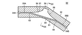
- FIG. 7 is a cross-sectional view showing a cross section taken along the line VII-VII in FIG.
- FIG. 8 is a cross-sectional view showing a cross section taken along line VIII-VIII of FIG.
- through hole 53 has tapered input / output ports 54A and 54B as the first end and the second end in order to increase the port through which delivery wire 104 is inserted to improve the insertability.
- the through hole 53 is provided between the input / output ports 54A and 54B, and has restraint portions 55A and 55B for restricting the movement of the delivery wire 104 in the direction other than the longitudinal axis.
- the diameter of the through hole 53 is slightly larger than the diameter of the delivery wire 104 (for example, 105% to 120% of the diameter of the delivery wire 104).
- the length of the through hole 53 along the longitudinal axis direction of the delivery wire 104 is several times or more the diameter of the delivery wire 104. Therefore, the delivery wire 104 is restrained from moving in directions other than the longitudinal direction at the restraint portions 55A and 55B.
- the through hole 53 allows the delivery wire 104 to be curved in an arc shape inside the through hole 53 and allows the degree of bending of the delivery wire 104 to be changed according to the compression force and the tension applied to the delivery wire 104. It is formed. That is, the through hole 53 is formed to be curved in a circular arc at the detection portion 56 inside the through hole 53 when the compression force and the tensile force in the longitudinal direction do not act on the delivery wire 104. In addition, when a compressive force acts on the delivery wire 104, the through hole 53 increases the degree of bending of the delivery wire 104 compared to when the compressive force and the tensile force do not act on the delivery wire 104. When a tensile force is applied, the degree of bending of the delivery wire 104 is reduced as compared with the case where a compressive force and a tensile force are not applied to the delivery wire 104.
- Such a configuration makes it possible to accurately detect the compressive force and the tensile force even when the longitudinal compressive force and the tensile force acting on the delivery wire 104 are very small.
- the main body 52 defines the bending direction of the delivery wire 104 inside the through hole 53 when longitudinal compressive force and tensile force act on the delivery wire 104. That is, the through hole 53 is bent between the two restraint portions 55A and 55B, and when the delivery wire 104 is inserted through the through hole 53, the through hole 53 has a curved shape. Further, the through hole 53 is formed so as to form a detection portion 56 in which the inner wall 57, 58 is separated from the inner wall 61 and the diameter of the through hole 53 is expanded between the two restraint portions 55A, 55B inside. .
- the restraint portions 55A and 55B are provided adjacent to the input / output port 54A and the input / output port 54B, respectively, and have an opening area S1 when cut in a plane perpendicular to the insertion direction of the delivery wire 104.
- the detecting unit 56 is provided between the constraining unit 55A and the constraining unit 55B, and has an opening area S2 larger than the opening area S1 when cut by a plane orthogonal to the insertion direction of the delivery wire 104.
- the detection unit 56 is formed such that the delivery wire 104 is curved in a circular arc, and is expanded in the inner circumferential direction and the outer peripheral direction of the curved delivery wire 104.
- the inner wall 57, 58 outside the curvature of the delivery wire 104 is expanded to form the detection portion 56.
- the inner wall 61 is formed in a planar shape.
- the operation of the delivery wire 104 in the direction parallel to the sheet of FIG. 7 is not restricted.
- the delivery wire 104 passes through the inside of the main body 52 while being bent at the detection unit 56.
- the height of the through hole 53 in the direction perpendicular to the sheet of FIG. 7 is slightly larger than the diameter of the delivery wire 104 (for example, 105% to 120% of the diameter of the delivery wire 104) ), The movement of the delivery wire 104 in the direction perpendicular to the paper surface of FIG. 7 is restrained. That is, in the input / output ports 54A and 54B and the detection unit 56, the cross-sectional shape of the through hole 53 in a cross section perpendicular to the longitudinal axis direction of the delivery wire 104 is rectangular.
- the bending direction of the delivery wire 104 inside the through hole 53 is defined, and the height of the peak of the bending portion of the delivery wire 104 (ie, when the longitudinal axial compressive force and tensile force act on the delivery wire 104)
- the delivery wire 104 is positioned such that the maximum value of the distance from the inner wall 61 to the delivery wire 104 is determined.
- a line sensor 80 is disposed to cross the cross section of the through hole 53 in the detection unit 56.
- the line sensor 80 is disposed across the inside of the detection unit 56 so as to extend from the inner wall 61 of the through hole 53 to the inside of a recess 59 described later that constitutes the inner wall of the through hole 53 facing the inner wall 61.
- the line sensor 80 has a locus of a peak of a curve formed by curving the delivery wire 104 in a circular arc shape when a compressive force and a tensile force in the longitudinal direction act on the delivery wire 104. It is arranged along.
- boundary portions 63 and 64 between the inner wall 61 and the restraint portions 55A and 55B in the detection portion 56 are formed to have a curved surface shape convex toward the inside of the through hole 53.
- the inner walls 57 and 58 are formed to have a curved surface shape convex toward the inside of the through hole 53.
- the inner wall 57 is formed in a curved shape contacting the inner wall of the through hole 53 in the constraining portion 55A
- the inner wall 58 is formed in a curved shape contacting the inner wall of the through hole 53 in the constraining portion 55B. This can prevent the delivery wire 104 from bending with plastic deformation.
- a recess 59 is formed between the inner wall 57 and the inner wall 58 of the detection unit 56.
- the recess 59 is formed such that the inner wall of the through hole 53 is recessed toward the outside of the main body 52 so that the inner wall of the through hole 53 between the inner wall 57 and the inner wall 58 of the detection unit 56 is further away from the inner wall 61 There is.
- the wall portion of the detection unit 56 is formed into a shape in which inner walls 57 and 58 having a curved surface shape convex toward the inside of the through hole 53 and a recess 59 are combined. Due to the shape of the detection unit 56, when a compressive force in the longitudinal direction acts on the delivery wire 104 in the detection unit 56 to bend the delivery wire 104, the through hole 53 in the outside of the curve of the delivery wire 104
- the delivery wire 104 can be curved along the inner wall (i.e., the inner wall 57 and the inner wall 58). Also, a portion of the delivery wire 104 can be curved away from the inner wall 57 and the inner wall 58. Also, as the compressive force increases, the distance between the contacts, which is the point at which the delivery wire 104 leaves the inner wall 57, 58, decreases.
- buckling of the delivery wire 104 can be suppressed inside the detection unit 56. That is, even when the delivery wire 104 with a small buckling load is used, the delivery wire 104 is bent without buckling in the detection unit 56, so that the degree of bending of the delivery wire 104 can be detected with high accuracy. By converting the degree of bending detected, the longitudinal compressive force acting on the delivery wire 104 can be measured.
- the concave portion 59 is formed in the detection portion 56, it is possible to measure the compression force acting on the delivery wire 104 with high accuracy over a wide range. That is, by detecting the height of the peak of the curve of the delivery wire 104 in the detection unit 56, the compression force acting on the delivery wire 104 is measured. At this time, if the apex of the curved portion of the delivery wire 104 in the detection unit 56, that is, the most distant point from the inner wall 61 in the delivery wire 104 in the detection unit 56 does not contact the inner wall of the detection unit 56, The compressive force acting on the delivery wire 104 can be measured.
- the recess 59 is formed, in order to contact the top of the curved portion of the delivery wire 104 with the inner wall of the detection portion 56, a greater longitudinal compression force is required. Therefore, the measurement range of the compressive force acting on the delivery wire 104 can be expanded.
- FIG. 9 is a schematic view showing the entire configuration of the measuring apparatus.
- measuring device 60 further includes a light source 81 for emitting light, a line sensor 80 which is a light receiver receiving light emitted from light source 81, and a lighting circuit 65 for causing light source 81 to emit light. And a conversion circuit 66.
- the line sensor 80 is a one-dimensional optical array sensor including a plurality of light receiving elements that receive light, and in which the plurality of light receiving elements are arranged in a line.
- the optical path from the light source 81 to the line sensor 80 is made of a translucent material through which light used for detection passes.
- the light source 81 and the line sensor 80 are disposed so as to sandwich the detection wire 56 so as to face each other with the delivery wire 104 interposed therebetween.
- the line sensor 80 is in the height direction of the peak of the curve of the delivery wire 104, that is, along the direction in which the peak of the curve of the delivery wire 104 moves when applying longitudinal compressive force and tensile force to the delivery wire 104.
- the line sensor 80 is disposed along a direction perpendicular to the extending direction of the inner wall 61, and is disposed orthogonal to the delivery wire 104 at the top of the peak of the curve.
- the line sensor 80 detects the degree of curvature of the delivery wire 104 by measuring the height h of the peak of the curvature of the delivery wire 104.
- the degree of bending of the delivery wire 104 is detected based on the shadow of the delivery wire 104 projected onto the line sensor 80. That is, when the line sensor 80 receives the light emitted by the light source 81, the delivery wire 104 is located above a light receiving element in the line sensor 80, and the light emitted by the light source 81 is blocked by the delivery wire 104. The amount of light received by the The position of the light receiving element corresponds to the degree of bending of the delivery wire 104.
- the light receiver disposed at the position facing the light source is not limited to the configuration that receives the transmitted light, but the light source and the light receiver are arranged side by side, and the light emitted from the light source is reflected at the position facing the light source.
- the degree of curvature of the linear body can be similarly detected by receiving the light reflected by the reflector among the light emitted by the light source with the light receiver.
- a one-dimensional array sensor such as a line sensor, even if using a two-dimensional array sensor in which a plurality of light receiving elements are arranged in a matrix, for example, on a plane, detection of the degree of bending of linear body Is possible.
- a lighting circuit 65 and a conversion circuit 66 are provided outside the main body 52.
- the lighting circuit 65 causes the light source 81 to emit light.
- the conversion circuit 66 is a signal indicating the degree of bending of the delivery wire 104 detected by the amount of light received by the line sensor 80 with respect to the amount of light emitted by the light source 81 and the longitudinal compressive force and tensile force acting on the delivery wire 104 Convert to and output.
- the conversion circuit 66 may have an amplifier circuit that amplifies the output of the line sensor 80.
- the conversion circuit 66 is based on a predetermined correlation between the degree of bending of the delivery wire 104 and the compressive force and tensile force acting on the delivery wire 104, and the compressive force and tensile force acting on the delivery wire 104 with the degree of bending of the delivery wire 104. Convert to a signal indicating.
- an optical element such as a lens, a slit, and a filter for blocking external light may be provided in the present optical system.
- FIG. 10 is a view showing a state in which a compressive force acts on the delivery wire 104 and the delivery wire 104 is bent inside the main body 52 in the cross-sectional view of FIG. 7.
- the state of the delivery wire 104 when no compressive force or tensile force is acting on the delivery wire 104 is indicated by p0.
- the delivery wire 104 is curved in an arc shape.
- the delivery wire 104 When the compressive force CP acts on the delivery wire 104, the delivery wire 104 is further curved than in the state p0, and the height of the peak of the curvature is increased h1 as compared to the state p0 (state p1).
- the delivery wire 104 When a large compressive force CP is applied to the delivery wire 104 compared to the state p1, the delivery wire 104 is further curved than the state p1, and the height of the peak of the curvature is further increased compared to the state p1 and compared to the state p0 h2 (h2> h1) increases (state p2).
- FIG. 11 is a view showing a state in which a tensile force is applied to the delivery wire 104 and the delivery wire 104 is curved inside the main body 52 in the cross-sectional view of FIG. 7.
- the state of the delivery wire 104 when the compressive force and the tensile force do not act on the delivery wire 104 is indicated by p0.
- the delivery wire 104 is curved in an arc shape.
- the degree of bending of the delivery wire 104 decreases more than in the state p0, and the height of the peak of the curvature decreases by h3 compared to the state p0 (state p3).
- the conversion circuit 66 delivers the detected degree of bending when the degree of bending of the delivery wire 104 is increased compared to the degree of bending of the delivery wire 104 when compression force and tensile force are not applied to the delivery wire 104. It is converted into a signal indicative of the compressive force acting on the wire 104. In addition, the conversion circuit 66 detects the degree of bending detected when the degree of bending of the delivery wire 104 is reduced as compared to the degree of bending of the delivery wire 104 when no compressive force or tensile force is acting on the delivery wire 104. Into a signal indicative of the tensile force acting on the delivery wire 104.
- line sensor 80 detects the position of the curved portion of delivery wire 104 inside through hole 53.
- the conversion circuit 66 delivers the displacement amount from the reference position as the delivery wire 104.
- the amount of displacement from the reference position is converted into a signal indicating tension applied to the delivery wire 104.
- the delivery wire When the line sensor 80 receives light emitted from the light source 81 disposed at a position facing the line sensor 80 with the detection unit 56 interposed therebetween, the delivery wire is placed on a light receiving element of the plurality of light receiving elements in the line sensor 80 When the position 104 is positioned, the light emitted from the light source 81 is blocked by the delivery wire 104, so that the amount of light received by the light receiving element is reduced.
- the position of the light receiving element it is possible to specify the position of the delivery wire 104 and to detect increase or decrease in the height of the peak of the curve of the delivery wire 104, that is, the degree of bending of the delivery wire 104.
- the conversion circuit 66 is configured to generate a predetermined correlation (for example, a certain amount of compression force or tension force) between the height of the peak of the curve of the delivery wire 104 detected by the line sensor 80 and the compression force and tension force acting on the delivery wire 104. Based on the tensile force and the corresponding set of curve peak heights, the peak height of the curve of the delivery wire 104 is converted to a signal indicative of the compressive and tensile forces acting on the delivery wire 104 and output Do. In this way, it is possible to measure the compressive and tensile forces acting on the longitudinal axis of the delivery wire 104.
- a predetermined correlation for example, a certain amount of compression force or tension force
- FIG. 12 is a diagram showing the correlation between the force acting on the linear body and the position of the linear body detected by the line sensor.
- FIG. 12 shows the results of measuring the force acting on the linear body and the position of the linear body detected by the line sensor.
- the horizontal axis indicates the action force p in the longitudinal direction acting on the delivery wire 104
- the vertical axis indicates the height h of the peak of the curve of the delivery wire 104.
- Conversion circuit 66 stores the correlation shown in FIG. 12, and based on this correlation, converts the electrical signal received from line sensor 80 into a signal indicative of the compressive force and tensile force acting on delivery wire 104. Do.
- the conversion circuit 66 may store the correlation shown in FIG. 12 as it is, or may store an expression that approximates the correlation shown in FIG.
- FIG. 13 is a diagram showing the procedure of the measurement method according to the first embodiment of the present invention.
- delivery wire 104 is inserted through through hole 53 of main body 52. That is, the delivery wire 104 is inserted into the through hole 53 formed to allow the delivery wire 104 to curve in an arc shape and to change the degree of bending of the delivery wire 104 according to the compressive force and the tensile force. .
- step (S110) the delivery wire 104 is inserted into the tube, and the distal end of the delivery wire 104 contacts the inner wall of the tube by operating from the outside of the tube.
- step (S120) when applying force in the longitudinal axis direction of the delivery wire 104 from the outside of the tube to further insert or withdraw the delivery wire 104, does the tip of the delivery wire 104 contact the inner wall of the tube?
- the operation of the delivery wire 104 is restricted, for example, by the delivery wire 104 being hooked to a tube in the body. Therefore, compressive force or tensile force acts in the longitudinal direction of the delivery wire 104.
- the bending degree of the delivery wire 104 is changed in the detection portion 56 inside the through hole 53 by the action of the compression force or the tension force.
- step (S140) the bending degree of the delivery wire 104 is detected by the line sensor 80.
- step (S150) delivery wire 104 detected in step (S140) based on a predetermined correlation between the degree of bending of delivery wire 104 and the compressive force and tensile force acting on delivery wire 104 by conversion circuit 66. Is converted into a signal indicative of the compressive or tensile force acting on the delivery wire 104.
- step (S160) a signal indicating the compression force or tension obtained by conversion from the degree of bending of the delivery wire 104 is output.
- the degree of bending of the delivery wire 104 is indicated by The sensor 80 detects this. Then, the degree of bending of the delivery wire 104 to be detected is converted by the conversion circuit 66 into a signal indicating longitudinal compressive force or tensile force acting on the delivery wire 104. Further, the line sensor 80 is provided at a position where the delivery wire 104 is operated outside the tube into which the delivery wire 104 is inserted, and the longitudinal compressive force and tensile force acting on the delivery wire 104 are measured. Compressive force and tensile force can be measured quantitatively even for ultra-fine delivery wires 104 where it is difficult to provide a pressure sensor.
- both the insertion force and the drawing force of the linear body can be measured.
- the linear body since it is easy to incorporate into a medical device because of its simple configuration, excessive load is applied to the human body and the linear body that is a treatment device in the insertion operation and withdrawal operation of the linear body inserted into the human body. Can issue a warning when Therefore, in the measuring device and the measuring method according to the first embodiment of the present invention, the linear body can be favorably operated with a simple configuration.
- the degree of bending of the delivery wire 104 when the same force acts is different. Therefore, when using a plurality of delivery wires 104 of different shapes and materials, the correlation between the degree of curvature of various linear bodies of different shapes and materials and the force in the longitudinal direction acting on the linear bodies is previously determined. The correlation is measured and stored in the conversion circuit 66.
- the measuring device 60 also includes a linear body selector 67 shown in FIG. 9, and the linear body selector 67 selects which correlation to use according to the linear body to be used. As a result, the same measuring device can be applied to the delivery wire 104 having various shapes and materials, so that the linear body used for various different applications can be used as it is, which is economical. .
- FIG. 14 is a diagram showing the configuration of the Y connector according to the first embodiment of the present invention.
- Y connector 31 includes measuring device 60, input ports 32 and 33, and output port 34.
- the Y connector is for inserting a linear body into a catheter when using a catheter, and an input port 32 which is an insertion port for the linear body, and physiological saline for injecting saline into the catheter. And an input port 33 which is a water inlet.
- the measuring device 60 is incorporated in a passage in the Y connector 31 that connects the input port 32 and the output port 34.
- the delivery wire 104 is, for example, a linear medical device such as a guide wire and a catheter inserted into a body vessel such as a blood vessel and a ureteral tube, and an embolic coil for embolicing an aneurysm. is there.
- the delivery wire 104 is guided to a target site in the body by an operation from the input port 32 side.
- the delivery wire 104 can be operated from the input port 32 of the Y connector 31, and a medicine can be injected from the input port 33.
- a medicine can be injected from the input port 33 to reduce the friction between the catheter and the guide wire.
- the blood vessel contrast agent can be injected from the input port 33 to inject the blood vessel contrast agent to the target site in the body.
- a Y connector is used when inserting the coil and delivery wire into the catheter. For this reason, integrating the Y connector and the measuring device 60 is very useful because the conventional usability of the Y connector does not change. Since the Y connector is disposable, the Y connector and the sensor housing may be separated.
- a line sensor 80 which is an optical sensor, is used as the measuring device 60 for measuring the compressive force acting on the delivery wire 104.
- an optical sensor As shown in FIG. 9, a translucent material such as a transparent resin material is provided between the light source 81 and the detection unit 56 and between the line sensor 80 and the detection unit 56. Can be placed. Since sensor components such as the light source 81 and the line sensor 80 can be included in the main body 52, the sensor components are not exposed to the detection unit 56. Therefore, the sensor component can be prevented from coming into contact with a liquid such as saline injected from the other input port 33 of the Y connector 31. Therefore, since it is not necessary to consider the occurrence of a defect such as failure of the sensor component in contact with the liquid, cleaning and sterilization of the Y connector 31 incorporating the measuring device 60 can be easily realized.
- the compressive force and the tensile force measured by the measuring device 60 are numerically or meter-displayed or graphically displayed Visualization equipment and hearing equipment that converts sound into a sound corresponding to compression and tension.
- the insertion device of the present embodiment can include either one of a visualization tool and a hearing aid, or can use both in combination.
- a sensor output control device 90 that controls the output of the visualization tool and the output of the hearing aid is electrically connected to the measurement device 60 by a wire 91.
- the sensor output control device 90 notifies the operator of the compressive force and tensile force acting on the delivery wire 104 by light or sound, and the amount of light is determined according to the magnitude of the compressive force and tensile force measured by the measuring device 60.
- the brightness, the wavelength of light, the frequency of light, the number of intermittently generated light per predetermined time, the volume, the wavelength of sound, the frequency of sound or the number of intermittently generated sound per predetermined time are changed.
- FIG. 1 exemplifies a display 93 as a visualization device that displays numerical values indicating the compressive force and the tensile force acting on the delivery wire 104 with the voltage output of the measuring device 60.
- the physician focuses on fluoroscopic images of the aneurysm 133 and the coil 101. Therefore, it is convenient to use a hearing aid to present the doctor with compressive and tensile forces acting on the delivery wire 104 when driven by the drive device 1 by sound.
- FIG. 15 is a diagram showing acoustic control performed by the sensor output control device in the insertion device according to the first embodiment of the present invention.
- the horizontal axis indicates the force (acting force) acting on the delivery wire 104
- the vertical axis indicates the frequency of the alarm sound.
- the compressive force (insertion force) is a positive acting force
- the tensile force (extraction force) is a negative acting force.
- the compressive force and the tensile force acting on the delivery wire 104 become excessively large, that is, when the compressive force acting on the delivery wire 104 exceeds the threshold value Ff 0, or the delivery wire 104 Controls the speaker 92 to generate a warning sound and the tone color of the warning sound in steps (like bass and treble, intermittent sound and continuous sound) as the compressive force and tensile force increase. Etc).
- the frequency stepwise according to the magnitude of the action force if the frequency is changed stepwise according to the magnitude of the action force, the abnormality is reported more reliably than the frequency is continuously changed according to the magnitude of the action force. can do. Also, by setting the frequency step to the scale, it is possible to more reliably notify of an abnormality.
- the sensor output control device 90 when the acting force on the delivery wire 104 is not more than the insertion force threshold Ff0 and not less than the tension force threshold Fb0, no large force is acting on the delivery wire 104 It does not generate a warning sound.
- the excessively large compressive force and tensile force acting on the delivery wire 104 can be presented to the doctor also by the change in the visual effect using light.
- the vertical axis in FIG. 15 may be replaced with the wavelength of light. That is, for example, when the compressive force and tensile force acting on delivery wire 104 become excessively large, that is, when the compressive force acting on delivery wire 104 exceeds threshold value Ff 0, or sensor delivery control device 90 delivers When the tensile force acting on the wire 104 falls below the threshold Fb0, the warning lamp 94 shown in FIG. 1 is controlled to generate a warning light, and the wavelength of the warning light is changed stepwise as the compression force and the tensile force increase. .
- the light emission color of the lamp may be changed before and after a predetermined threshold.
- the light emission color and the blink rate of the lamp may be changed stepwise as the compression force and the tension force increase.
- the speaker 92 and the warning lamp 94 may be used in combination. Abruptly changing the visual or acoustic effect before and after the threshold value is more effective because it can reliably alert the physician.
- FIG. 16 is a diagram showing acoustic control performed by the sensor output control device in the insertion device according to the first embodiment of the present invention.
- the horizontal axis indicates the force (acting force) acting on the delivery wire 104
- the vertical axis indicates the size (volume) of the alarm sound.
- the insertion force is a positive acting force
- the drawing force is a negative acting force.
- the speaker 92 is controlled to generate a warning sound, and the volume of the warning sound is increased with the increase of the compression force and the tensile force.
- the volume of a warning sound is set as a predetermined value between 0% and 100% of a reference value.
- the acting force on the delivery wire 104 is at least the insertion force threshold Ff1 and less than the threshold Ff2, or the acting force on the delivery wire 104 is larger than the withdrawal force threshold Fb2 and not more than the threshold Fb1. If so, the volume of the warning sound is continuously changed according to the compression force and the tension force acting on the delivery wire 104.
- the sensor output control device 90 generates an alarm sound even if the acting force on the delivery wire 104 exceeds the insertion force threshold Ff2 or if the acting force on the delivery wire 104 falls below the withdrawal force threshold Fb2. Make the volume of the constant at 100% of the reference value.
- the sensor output control device 90 when the acting force on the delivery wire 104 is not more than the insertion force threshold Ff0 and not less than the tension force threshold Fb0, no large force is acting on the delivery wire 104 It does not generate a warning sound.
- the vertical axis in FIG. 16 may be replaced with the luminance of light. That is, for example, when the compressive force and tensile force acting on delivery wire 104 become excessively large, that is, when the compressive force acting on delivery wire 104 exceeds threshold value Ff 0, or sensor delivery control device 90 delivers When the tensile force acting on the wire 104 falls below the threshold Fb0, the warning lamp 94 is controlled to generate a warning light, and the brightness of the warning light is increased along with the increase of the compressive force and the tensile force as in the above warning sound. Change
- FIG. 17 is a diagram showing acoustic control performed by the sensor output control device in the insertion device according to the first embodiment of the present invention.
- the horizontal axis indicates the force (acting force) acting on the delivery wire 104
- the vertical axis indicates the number of sound pulses generated in a predetermined time.
- the insertion force is a positive acting force
- the drawing force is a negative acting force.
- the speaker 92 is controlled to increase the number of alarm sound pulses, that is, the number of alarm sounds generated intermittently in a predetermined time.
- the acting force on the delivery wire 104 is at least the insertion force threshold Ff0 and less than the threshold Ff1, or the acting force on the delivery wire 104 is larger than the withdrawal force threshold Fb1 If the threshold value Fb0 or less, the number of pulses of the warning sound is continuously changed according to the compression force and the tension force acting on the delivery wire 104. Further, in the sensor output control device 90, when the acting force on the delivery wire 104 is at least the insertion force threshold Ff1 and less than the threshold Ff2, or the acting force on the delivery wire 104 is larger than the withdrawal force threshold Fb2 and not more than the threshold Fb1.
- the variation width of the number of pulses of the warning sound according to the compressive force and the tensile force acting on the delivery wire 104 is further increased. Further, in the sensor output control device 90, even if the acting force on the delivery wire 104 becomes equal to or more than the threshold Ff2 of the insertion force or the acting force on the delivery wire 104 becomes equal to or less than the threshold Fb2 of the drawing force, The number of pulses of is made constant at a predetermined value PN.
- the sensor output control device 90 when the acting force on the delivery wire 104 is not more than the insertion force threshold Ff0 and not less than the tension force threshold Fb0, no large force is acting on the delivery wire 104 It does not generate a warning sound.
- the sensor output control device 90 sets the frequency of the sound pulse high when a compressive force is applied to the delivery wire 104, and the frequency of the sound pulse when a tensile force is applied to the delivery wire 104. Set low. Thereby, the doctor can recognize the direction of the action force.
- the vertical axis in FIG. 17 may be replaced with the number of light pulses generated in a predetermined time, and the frequency may be replaced with the wavelength of light. That is, for example, when the compressive force and tensile force acting on delivery wire 104 become excessively large, that is, when the compressive force acting on delivery wire 104 exceeds threshold value Ff 0, or sensor delivery control device 90 delivers When the tensile force acting on the wire 104 falls below the threshold Fb0, the warning lamp 94 is controlled to increase the number of pulses of the warning light, that is, the number (flashing number) of warning lights generated intermittently in a predetermined time.
- the sensor output control device 90 sets the wavelength of the light pulse long when a compressive force is applied to the delivery wire 104, and the wavelength of the optical pulse when a tensile force is applied to the delivery wire 104. Set short. Thereby, the doctor can recognize the direction of the action force.
- the doctor can be surely recognized by the warning sound and the lighting of the lamp. Can. Therefore, even when one doctor operates both the child catheter 102 and the delivery wire 104 in the coil embolization treatment, the insertion force acting on the delivery wire 104 is excessive, and an excessive load acts on the cerebral aneurysm 133. Can be easily suppressed.
- the insertion device includes the drive device 1 for moving the delivery wire 104 in the longitudinal axis direction, and foot switches 41 and 46 for transmitting a signal for controlling start and stop of the drive device 1.
- a doctor who manually operates the child catheter 102 through which the delivery wire 104 is inserted can move the delivery wire 104 by operating the foot switches 41 and 46 with his / her feet, and the ease of operation of the insertion device Is improved. Therefore, the operation of the child catheter 102 and the delivery wire 104 can be realized by one doctor.
- the insertion device includes a measuring device that measures the compressive force and tensile force in the longitudinal direction acting on the delivery wire 104, and the operator with the compressive force and the tensile force measured by the measuring device. And a reporting device for reporting.
- the coil 101 at the tip of the delivery wire 104 can be reliably recognized by the doctor when the compression force and the tension force acting on the cerebral aneurysm 133 increase, so an excessive load acts on the cerebral aneurysm 133. Can be prevented.
- the coil 101 at the tip of the delivery wire 104 reliably prevents an excessive load from acting on the cerebral aneurysm 133. Can further improve the ease of operation of the insertion device.
- the drive device 1 for moving the delivery wire 104 in the longitudinal axis direction includes a reduction gear 9 that reduces the rotational speed of the rotational force generated by the motor 3 and outputs the reduced power.
- a reduction gear 9 that reduces the rotational speed of the rotational force generated by the motor 3 and outputs the reduced power.
- the motor 3 and the reduction gear 9 are contained in a case (that is, in the small chamber 2 b) formed by the housing 2 and the partition 16, and a hole 16 a is formed in the partition 16.
- the rotary shaft 4 transmitting the rotational force passes through the hole 16a.
- a seal 19 is provided which is in contact with the outer peripheral surface, which is the rotation surface of the rotary shaft 4, and shields the inside of the small chamber 2b from the outside.
- the rotational surfaces 5a and 6a of the drive roller 5 and the driven roller 6 are formed of an elastic material. Furthermore, a feed groove 5 b is formed on the rotational surface 5 a of the drive roller 5, and the delivery wire 104 is disposed inside the feed groove 5 b. As a result, when the lid member 10 is closed, the delivery wire 104 can be correctly installed between the driving roller 5 and the driven roller 6 so as not to be pinched by other portions. Moreover, since the frictional force generated between the rotation surfaces 5a and 6a and the delivery wire 104 sandwiched between the rotation surfaces 5a and 6a can be increased, the delivery wire 104 rotates while the delivery wire 104 is moving. Slippage with respect to the surfaces 5a and 6a can be suppressed.
- the insertion device for inserting the delivery wire 104 having the coil 101 for embolic treatment for embolizing the cerebral aneurysm 133 at the tip end into the blood vessel 132 in the human body 131 has been described.
- the insertion device according to the present invention inserts a medical linear body, which is a flexible linear medical device, into a body vessel such as a blood vessel, ureter, bronchus, digestive tract or lymphatic vessel,
- the insertion device may be any insertion device that guides to the target site by the operation from the above.
- the medical linear body may be a catheter or a guide wire.
- the present embodiment relates to an insertion device in which the shape of the through hole is changed as compared with the insertion device according to the first embodiment.
- the contents other than the contents described below are the same as those of the insertion device according to the first embodiment.
- the measurement apparatus is suitable for cerebral aneurysm coil embolization which is a therapeutic method for preventing the rupture of cerebral aneurysm which is the cause of subarachnoid hemorrhage.
- the present treatment is a treatment in which a coil is tightly packed in an aneurysm by using a catheter as a conduit.
- FIG. 18 is a view showing the configuration of a coil for cerebral aneurysm coil embolization.
- the coil for cerebral aneurysm coil embolization includes a coil portion 82 used for embolization, and a delivery wire portion 83 for feeding the coil portion 82.
- the coil for cerebral aneurysm coil embolization has a helical shape or a saddle-shaped shape that matches the size of the aneurysm, and it is stretched straight as shown in FIG. 18 before use to facilitate insertion into the catheter. It is done.
- the operator operates the delivery wire portion 83 to fill the coil portion 82 into the aneurysm.
- the operator changes the coil section to a different size after inserting the coil section 82, and withdraws the delivery wire section 83 after leaving the coil section 82.
- the coil section 82 is flexible, it will stretch if it is pulled out forcibly. Therefore, it is important to pull out the coil portion 82 without applying an excessive tensile force to the coil portion 82.
- the coil portion 82 is flexible, it is housed in the sheath 85 before use.
- the sheath 85 and the inlet of the catheter are aligned so that the coil portion 82 does not go out.
- the delivery wire portion 83 is pushed to move the coil portion 82 into the catheter.
- the sheath 85 is pulled out of the delivery wire portion 83 and the delivery wire portion 83 is manipulated.
- the sheath 85 Since the sheath 85 has a larger diameter than the delivery wire portion 83, the sheath 85 can not be inserted into the main body 52 of the measuring device 60 according to the first embodiment of the present invention. When the sheath 85 is removed and the coil portion 82 is inserted into the measuring device 60, the coil portion 82 spreads in the detection portion 56.
- a penetration hole is formed as follows.
- FIG. 19 is a cross-sectional view showing the configuration of a measurement apparatus according to the second embodiment of the present invention.
- FIG. 19 corresponds to FIG. 7 in the first embodiment of the present invention.
- FIG. 20 is a cross-sectional view showing a cross section taken along line XX-XX in FIG.
- FIG. 20 corresponds to FIG. 8 in the first embodiment of the present invention.
- FIG. 21 is a view showing a state in which the sheath 85 is inserted into the main body 52 in the cross-sectional view of FIG.
- through hole 53 in measuring device 62 includes a sheath groove 84 which is a dedicated groove through which sheath 85 passes. More specifically, the sheath groove 84 is provided between the restraint portion 55A and the restraint portion 55B, is connected to the detection portion 56, and the insertion direction of the delivery wire 104 and the radial direction of the delivery wire 104 curved in an arc shape. The length in the perpendicular direction is larger than the detection unit 56.
- the sheath 85 can pass only the sheath groove 84 between the restraint portions 55A and 55B. Then, when the sheath 85 is passed through the main body 52, it becomes as shown in FIG.
- the delivery wire portion 83 Connect the measuring device 62 and the catheter, and align the sheath 85 with the mouth of the catheter. Then, after the delivery wire portion 83 is pushed to put all the coil portions 82 into the catheter, when the sheath 85 is pulled out from the main body 52, the delivery wire portion 83 remains in the main body 52. At this time, the delivery wire portion 83 is curved due to its rigidity, and since the delivery wire portion 83 is thinner than the sheath 85, the delivery wire portion 83 moves from the sheath groove 84 to the detection portion 56 and curves similar to the measuring device 60 as shown in FIG. It becomes a state.
- the portion of the through hole 53 other than the sheath groove 84 has a width slightly larger than the diameter of the delivery wire portion 83. Therefore, similarly to the measuring device 60, the position of the linear body in the detection unit 56 is uniquely determined for the acting force, and the sheath 85 can be passed without degrading the detection accuracy of the acting force. Become.
- the sheath groove 84 is provided in a portion of the detection unit 56 where the delivery wire portion 83 does not pass. That is, the sheath groove 84 is provided on the opposite side of the delivery wire 104 in the bending direction. The sheath groove 84 is connected to the end of the detection portion 56 on the inner peripheral side of the delivery wire 104 curved in an arc shape. With such a configuration, the sheath groove 84 can be easily created.
- the present embodiment relates to an insertion device in which the speed control of the delivery wire is changed as compared with the insertion device according to the first embodiment.
- the contents other than the contents described below are the same as those of the insertion device according to the first embodiment.
- FIG. 22 is a view showing the configuration of the insertion device according to the third embodiment of the present invention.
- the drive control device 40 delivers the delivery wire by the drive device 1 based on the longitudinal axial compressive force and tensile force acting on the delivery wire 104 measured by the measuring device 60.
- the drive speed of the delivery wire 104 is controlled.
- FIG. 23 is a diagram showing drive speed control performed by the insertion device according to the third embodiment of the present invention.
- the horizontal axis indicates the force (acting force) acting on the delivery wire 104
- the vertical axis indicates the ratio of the actual driving speed to the set speed of the delivery wire 104.
- the insertion force is a positive acting force
- the drawing force is a negative acting force.
- the drive control device 40 performs control to lower the drive speed of the delivery wire 104 from the set speed when an excessive insertion force and withdrawal force act on the delivery wire 104.
- the drive control device 40 controls the drive device 1 when the compressive force measured by the measuring device 60 exceeds a predetermined threshold or when the tensile force measured by the measuring device 60 exceeds a predetermined threshold. By doing this, the moving speed of the delivery wire 104 is reduced or the movement of the delivery wire 104 is stopped according to the amount by which the compressive force and the tensile force exceed the respective threshold values.
- the drive control device 40 continuously reduces the insertion speed from the set speed. Then, when the insertion force of the delivery wire 104 exceeds the threshold Ff2, the drive control device 40 stops the drive of the delivery wire 104.
- the drive control device 40 continuously decreases the drawing speed from the set speed. Then, when the tension on the delivery wire 104 becomes smaller than the threshold Fb2, the drive control device 40 stops the drive of the delivery wire 104.
- the insertion apparatus it is possible to more reliably prevent the excessive insertion and extraction forces from acting on the human body, the treatment device and the medical linear body.
- the present embodiment relates to an insertion device in which the method of measuring the compressive force and the tensile force acting on the linear body is changed as compared with the insertion device according to the first embodiment.
- the contents other than the contents described below are the same as those of the insertion device according to the first embodiment.
- FIG. 24 is a diagram showing a configuration of a drive device in an insertion device according to a fourth embodiment of the present invention.
- the insertion device 503 includes the drive device 1, a driving force conversion unit 76, and a driving force display unit 77.
- Drive device 1 includes a speed control unit 71, a current detector 72, a motor 73, an encoder (rotational speed detection unit) 74, and a speed detection unit 75.
- the motor 73 corresponds to the motor 3 in the insertion device 501.
- the driving force on the delivery wire 104 can be detected by the load of the motor 73 by eliminating the reduction gear 9 or reducing the reduction gear ratio of the reduction gear 9 in the drive device 1 according to the first embodiment of the present invention I assume.
- the force acting on the delivery wire 104 can be estimated from the drive current of the motor 73.
- the output of the motor 73 affects the load of the delivery wire 104, in order to control the speed of the motor 73, it is necessary to provide the motor with a rotary encoder.
- the motor 73 generates a rotational force for moving the delivery wire 104 in the longitudinal direction based on the supplied drive current.
- the encoder 74 detects the rotational speed of the motor 73.
- the speed detection unit 75 detects the moving speed of the delivery wire 104 in the longitudinal direction based on the rotational speed detected by the encoder 74.
- the speed control unit 71 generates a drive current so that the moving speed detected by the linear body speed detection unit 75 becomes equal to the commanded speed received from the drive control device 40.
- the current detector 72 detects a drive current.
- the driving force conversion unit 76 measures the compressive force and the tensile force acting on the delivery wire 104 based on the driving current detected by the current detector 72. That is, the driving force conversion unit 76 converts the driving current detected by the current detector 72 into driving force. The driving force conversion unit 76 replaces the measuring device 60 in the insertion device 501.
- the driving force display unit 77 displays the driving force converted by the driving force conversion unit 76. Similar to the insertion device 501, the insertion device 503 may be configured to emit sound and light based on the driving force converted by the driving force conversion unit 76.
- the present embodiment relates to a recording system for recording the measurement results of the insertion device.
- the contents other than the contents described below are the same as those of the insertion device according to the first embodiment.
- FIG. 25 is a diagram showing the configuration of a linear object operation recording system according to a fifth embodiment of the present invention.
- the linear body operation recording system 301 includes an image camera 201, a microphone 202, an insertion device 501, modulators 203 and 204, a mixer 205, an image recording device 206, and an image monitor. 207, a speaker 208, a separator 209, demodulators 210 and 211, an acting force display unit 212, and a driving speed display unit 213.
- the video camera 201 captures an X-ray fluoroscopic image of the distal end portion of the delivery wire 104 inserted in a tube in the body and the periphery thereof to generate a video signal.
- the video signal generated by the video camera 201 is supplied to the image input terminal of the video recording device 206.
- the microphone 202 converts voice during surgery using the delivery wire 104 into a voice signal.
- the audio signal generated by the microphone 202 is supplied to one of the stereo audio input terminal pairs of the video recording device 206 (the left audio input terminal in FIG. 25).
- the measuring device 60 in the insertion device 501 measures the compressive force and tensile force in the longitudinal axis direction of the delivery wire 104, and outputs a signal indicating the measured value.
- the modulator 203 modulates the signal received from the measuring device 60 and outputs it.
- the drive control device 40 in the insertion device 501 outputs a signal indicating the drive speed of the delivery wire 104.
- Modulator 204 modulates and outputs the signal received from drive control device 40.
- the mixer 205 mixes the output signal of the modulator 203 and the output signal of the modulator 204.
- the signal mixed by the mixer 205 is applied to the other terminal (the right audio input terminal in FIG. 25) of the stereo audio input terminal pair of the video recording device 206.
- the signal mixed by the mixer 205 is recorded by the video recording device 206 together with the X-ray fluoroscopic image from the video camera 201 and the audio from the microphone 202 on a video recording medium such as a DVD recorder or a video tape.
- the video recording device 206 synchronizes the X-ray fluoroscopic image from the video camera 201, the audio from the microphone 202, the compression force and tension force in the longitudinal axis direction of the delivery wire 104, and the driving speed of the delivery wire 104. Record, that is, record them in association with each other in time.
- the video monitor 207 displays an X-ray fluoroscopic image based on the video signal received from the video recording device 206.
- the speaker 208 emits a sound based on the audio signal received from the video recording device 206.
- the separator 209 is, for example, a filter, and separates the mixed signal received from the video recording device 206.
- the demodulator 210 demodulates the signal separated by the separator 209 and outputs a signal indicating a force.
- the demodulator 211 demodulates the signal separated by the separator 209 and outputs a signal indicating the driving speed.
- the acting force display unit 212 displays the acting force based on the signal received from the demodulator 211.
- Drive speed display portion 213 displays the drive speed based on the signal received from demodulator 210.
- the recording is performed by mixing the audio signal with the signal indicating the acting force and the driving speed.
- the recording may be performed by mixing with the video signal.
- the present embodiment relates to an insertion device in which the assembly structure is changed as compared with the insertion device according to the first embodiment.
- the contents other than the contents described below are the same as those of the insertion device according to the first embodiment.
- FIG. 26 is a view showing a separation structure of the Y connector, the measuring device and the drive device in the insertion device according to the sixth embodiment of the present invention.
- the Y connector 31 is detachable from the line sensor 80.
- the line sensor housing 51 and the light source 81 are integrated with the drive device 1 via the base 22, for example.
- the light source 81 is movable, and after the Y connector 31 is fitted into the line sensor housing 51 at the fitting groove 24, the light source 81 is shifted to a predetermined position.
- the line sensor housing 51 and the light source 81 face each other with the delivery wire 104 interposed therebetween.
- the lens 23 and the line sensor 80 are incorporated in the line sensor housing 51.
- the marker 21 is provided in the Y connector 31, the position of the marker 21 is detected in the line sensor housing 51, and the measurement result of the acting force is corrected based on this position. Thereby, it is possible to prevent the conversion in the action force measurement based on the deflection of the delivery wire 104 from being erroneous due to the fitting position.
- the present embodiment relates to an insertion device provided with a light source in a line sensor housing as compared with the insertion device according to the sixth embodiment. Except for the contents described below, it is the same as the insertion device according to the sixth embodiment.
- FIG. 27 is a view showing a separation structure of the Y connector, the measuring device and the drive device in the insertion device according to the seventh embodiment of the present invention.
- the reflection plate 27 is installed on the Y connector 31, and the light source 81 is aligned with the line sensor 80 and installed on the housing 51.
- the light output from the light source 81 is reflected by the reflection plate 27, and the reflected light is received by the line sensor 80.
- the Y connector 31 and the line sensor housing 51 can be separated, and in the insertion device 504 using a movable light source, the Y connector 31 is integrated by integrating the reflection plate 27 and the Y connector 31. After being attached to the line sensor housing 51, the inconvenience of shifting the light source 81 to a predetermined position can be eliminated.
- FIG. 28 is a diagram showing the configuration of a training device according to the eighth embodiment of the present invention.
- training device 302 includes insertion device 501 and simulator 26.
- the compressive force or tensile force is displayed Displayed by the container 93.
- the simulator 26 simulates the human body and displays an equivalent to a fluoroscopic image of a human body tube.
- An operator performing medical device training operates the delivery wire 104 while looking at the display image of the simulator 26.
- the simulator 26 changes the insertion resistance and the withdrawal resistance to the inserted delivery wire 104.
- a warning sound is output from the speaker 92 when the compressive force and the tensile force acting on the delivery wire 104 are equal to or greater than predetermined threshold values.
- the measurement device 501 and the simulator 26 may be integrated. Further, instead of the display 93, the compressive force and the tensile force acting on the delivery wire 104 may be additionally displayed on the simulated fluoroscopic image displayed by the simulator 26.
- Such a configuration makes it possible to quantify the operation of a skilled operator and to improve the procedure of an inexperienced operator at an early stage.
- the operator's operation can be recorded together with the fluoroscopic image as a record during the operation.
- Reference Signs List 1 drive unit 2 housing, 2a large chamber, 2b small chamber, 3 motor, 4 rotating shaft, 5a rotating surface, 5a groove, 5 driving roller, 6a rotating surface, 6 driven roller, 7 support member, 8 elastic body, 9 deceleration , 10 lid members, 11 hinges, 12 levers, 13 protrusions, 14 locking portions, 15 elastic portions, 16a holes, 16 partitions, 17 guiding grooves, 18 protruding portions, 19 sealing portions, 21 markers, 22 bases, Reference Signs List 23 lens 24 fitting groove 26 simulator 27 reflecting plate 31 Y connector 32 input port 33 input port 34 output port 40 drive control device 41 insertion foot switch 42 wiring 43 insertion speed command portion , 44 wiring, 45, 50 volume switch, 46 extraction foot switch DESCRIPTION OF SYMBOLS 47 Wiring, 48 drawing speed instruction
Abstract
An insertion device is a device for inserting a medical linear body (104) into a tube in the interior of the body. The insertion device is provided with: a drive device (1) for moving the medical linear body (104) in the longitudinal axis direction; a measurement device (60) for measuring a compressive force or a tensile force acting in the longitudinal axis direction on the medical linear body (104); and informing devices (92-94) for informing the operator of the compressive force or the tensile force measured by the measurement device (60).
Description
この発明は、挿入装置、訓練装置および記録システムに関し、特に、医療用線状体を体内の管へ挿入する挿入装置、訓練装置および記録システムに関する。
The present invention relates to an insertion device, a training device and a recording system, and more particularly to an insertion device, a training device and a recording system for inserting a medical linear body into a pipe in the body.
可撓性を有する線状体は、体内の管の中へ挿入される線状の医療器具として実用化されている。たとえば、血管、尿管、気管支、消化管あるいはリンパ管などの体内にある管に挿入されるガイドワイヤやカテーテル、また、動脈瘤を塞栓するための塞栓用コイルが先端に付いたワイヤなどが知られている。これらの線状体を体内の管の中へ挿入し、体外からの操作によって目的部位まで誘導する。
Flexible linear bodies have been put to practical use as linear medical devices to be inserted into tubes in the body. For example, a guide wire or a catheter inserted into a vessel in the body such as a blood vessel, ureter, bronchus, digestive tract or lymph vessel, or a wire with an embolic coil for embolization of an aneurysm is known. It is done. These linear bodies are inserted into a vessel in the body and guided to the target site by manipulation from outside the body.
線状体が挿入される管は必ずしも直線状ではなく、部分的に屈曲および分岐をしている場合が多い。また、管の径は必ずしも一定ではなく、管自体が細くなっていたり、血管内に生じる血栓などの管内部にある障害物によって管の径が細くなっていたりする場合がある。しかし、従来の線状体では、線状体の進行方向前方の状況を検知する手段がなく、線状体の操作を操作者の勘に頼らざるを得ず、体外からの誘導操作には熟練が必要であった。そこで、線状体の進行方向前方における障害物の存在を検知する装置として、線状体の先端に圧力センサを設ける装置が開示されている(たとえば特許文献1(特開平10-263089号公報)参照)。
The tube into which the linear body is inserted is not necessarily linear, but is often partially bent and branched. Further, the diameter of the tube is not always constant, and the tube itself may be thin or the diameter of the tube may be reduced due to an obstacle inside the tube such as a thrombus generated in the blood vessel. However, in the conventional linear body, there is no means for detecting the situation in the forward direction of the linear body, and the operation of the linear body can not but rely on the operator's intuition, and is skilled in guiding operation from outside the body Was necessary. Therefore, as a device for detecting the presence of an obstacle ahead of the linear body in the direction of travel, a device having a pressure sensor at the tip of the linear body is disclosed (for example, Patent Document 1 (Japanese Patent Application Laid-Open No. 10-263089) reference).
しかしながら、線状体の先端に圧力センサを設ける装置は、特に極細の線状体については実現性に困難を伴う。たとえば脳血管に挿入するガイドワイヤの場合、その直径は0.35mm程度であり、このような極細の線状体の先端に小型の圧力センサを設けることは困難である。また、圧力センサの信号を外部に取り出すために、線状体の中に配線を挿通するのは、さらなる困難を要する。
However, an apparatus for providing a pressure sensor at the end of a linear body is difficult to realize, particularly for a very thin linear body. For example, in the case of a guide wire to be inserted into a cerebral blood vessel, its diameter is about 0.35 mm, and it is difficult to provide a small pressure sensor at the tip of such a very thin linear body. Moreover, in order to take out the signal of a pressure sensor outside, inserting a wiring in a linear body requires the further difficulty.
また、線状体が挿入される管が屈曲している場合、および管の径が細くなっている場合には、線状体の挿入抵抗は、管との摩擦の影響を受ける。よって、線状体の先端に設ける圧力センサの出力と、操作者の挿入時の力覚とが必ずしも一致しない場合がある。したがって、線状体の先端に圧力センサを設ける装置を用いる場合においても、操作者が外部において指先で把持した線状体の挿入抵抗の力覚情報に基づいて、すなわち操作者の勘に頼って、線状体の操作を実施することになる。その上、操作者の力覚は操作者しか知ることができないため、熟練操作者の手技を定量化し経験の少ない操作者へ伝授するのは困難である。
Moreover, when the tube into which the linear body is inserted is bent and when the diameter of the tube is narrowed, the insertion resistance of the linear body is affected by the friction with the tube. Therefore, the output of the pressure sensor provided at the tip of the linear body may not necessarily coincide with the force sense at the time of insertion of the operator. Therefore, even in the case of using a device in which a pressure sensor is provided at the tip of a linear body, based on the force sense information of the insertion resistance of the linear body gripped by the operator with a fingertip outside, that is, relying on the operator's intuition , To operate the linear body. Moreover, since only the operator can know the force sense of the operator, it is difficult to quantify the skill of the skilled operator and transfer it to the less experienced operator.
さらに、異なる用途に適応するための種々の形状および材質を有する線状体を用意し、それぞれに圧力センサを設けることは、不経済であり、製造コストの増大を招く。
Furthermore, it is uneconomical to provide linear bodies of various shapes and materials for adapting to different applications, and to provide each with a pressure sensor, resulting in an increase in manufacturing cost.
このような問題点を解決するための技術として、たとえば、特許文献2(特開2007-292711号公報)には、以下のような構成が開示されている。すなわち、可撓性を有する線状体に作用する長手軸方向の圧縮力を計測する計測装置であって、上記線状体が貫通する貫通孔が形成される本体を備え、上記線状体に上記圧縮力が作用するとき、上記貫通孔の内部において上記線状体が所定の方向へ湾曲し、さらに、上記湾曲の度合いを検出するセンサと、検出される上記湾曲度合いを、上記線状体に作用する上記圧縮力へ変換する、変換回路とを備える。
For example, Patent Document 2 (Japanese Patent Application Laid-Open No. 2007-292711) discloses the following configuration as a technique for solving such problems. That is, a measuring device for measuring a compressive force in the longitudinal direction acting on a flexible linear body, the linear body includes a main body in which a through hole through which the linear body penetrates is formed. When the compressive force acts, the linear body curves in a predetermined direction inside the through hole, and further, a sensor that detects the degree of the curve, the detected degree of curvature, the linear body And converting the compression force acting on the
特許文献1および2に記載の構成は、線状体に作用している圧縮力を測定するものである。一方、線状体に作用している引張力を測定する技術として、たとえば、特許文献3(特開2002-90239号公報)には、以下のような構成が開示されている。すなわち、線状体に作用する引張力を検出する線状体張力検出装置において、支持体に、線状体の移動を許容して該線状体の途中箇所に対して自在に着脱可能とされ、該支持体の両端部に設けられた取付部と、これら取付部の中央部に設けられ、線状体に対して直交方向に張り出して線状体を屈曲させる屈曲部と、この屈曲部によって屈曲させられた線状体が直線状に戻ろうとする際に該線状体から与えられる力を検出する検出器とを備え、検出器によって検出された力から、引張力を検出する。
The configurations described in Patent Documents 1 and 2 measure the compressive force acting on the linear body. On the other hand, as a technique for measuring a tensile force acting on a linear body, for example, Patent Document 3 (Japanese Patent Application Laid-Open No. 2002-90239) discloses the following configuration. That is, in the linear body tension detection device for detecting a tensile force acting on the linear body, the support allows movement of the linear body and can be freely attached to and detached from an intermediate position of the linear body. A mounting portion provided at both ends of the support, a bending portion provided at a central portion of the mounting portion and extending in a direction orthogonal to the linear body to bend the linear body, and the bending portion And a detector that detects a force applied from the bent linear body when the linear body tries to return linearly, and a tensile force is detected from the force detected by the detector.
最近、カテーテルを使用した治療などの、低侵襲の外科手術が行われている。カテーテルを使用した治療には、たとえば、コイル塞栓術治療が挙げられる。コイル塞栓術治療とは、脳動脈瘤内にコイルを留置して塞栓させ、くも膜下出血の原因である脳動脈瘤の破裂を防止する治療である。図29は、コイル塞栓術治療に用いられる医療器具を示す模式図である。
Recently, minimally invasive surgery has been performed, such as treatment with a catheter. Treatment using a catheter includes, for example, coil embolization treatment. The coil embolization treatment is a treatment that places a coil in the cerebral aneurysm and embolizes it, and prevents the rupture of the cerebral aneurysm which is the cause of the subarachnoid hemorrhage. FIG. 29 is a schematic view showing a medical device used for coil embolization treatment.
図29に示す医療器具100において、脳動脈瘤133をコイル塞栓させるための白金製のコイル101は、デリバリーワイヤ104の先頭に接続されている。デリバリーワイヤ104が内部に挿通されるカテーテルは、親カテーテル103を外管とし、子カテーテル102を内管とする、二重管カテーテルである。子カテーテル102は中空であり、デリバリーワイヤ104は子カテーテル102の中空部に挿入される。デリバリーワイヤ104はYコネクタ121に挿入され、子カテーテル102はYコネクタ111に挿入されている。
In the medical device 100 shown in FIG. 29, a platinum coil 101 for coiling the cerebral aneurysm 133 is connected to the head of the delivery wire 104. The catheter through which the delivery wire 104 is inserted is a double tube catheter in which the parent catheter 103 is an outer tube and the child catheter 102 is an inner tube. The child catheter 102 is hollow, and the delivery wire 104 is inserted into the hollow portion of the child catheter 102. The delivery wire 104 is inserted into the Y connector 121, and the child catheter 102 is inserted into the Y connector 111.
Yコネクタ121の入り口付近の把持部106において、医師がデリバリーワイヤ104を操作する。Yコネクタ111の入り口付近の把持部105において、他の医師がカテーテル102を操作する。つまり、Yコネクタ111,121の入り口付近において、二人の医師がそれぞれデリバリーワイヤ104と子カテーテル102とを操作する。
A doctor operates the delivery wire 104 at the grip portion 106 near the entrance of the Y connector 121. Another doctor operates the catheter 102 at the grip portion 105 near the entrance of the Y connector 111. That is, near the entrance of the Y connectors 111 and 121, two doctors operate the delivery wire 104 and the child catheter 102, respectively.
Yコネクタ111,121には3つの接続ポートがある。1つはカテーテルの接続ポート、他の1つはカテーテルやデリバリーワイヤなどの線状体を挿入するポート、他の1つは生理食塩水や薬剤の入力ポート112,122である。
The Y connectors 111 and 121 have three connection ports. One is a connection port of a catheter, the other is a port for inserting a linear body such as a catheter or a delivery wire, and the other is an input port 112, 122 for saline or medicine.
親カテーテル103は、人体131の血管132内に挿入されており、先端が脳動脈瘤133の近傍部まで達している。子カテーテル102は、親カテーテル103の内部に挿入されており、親カテーテル103の先端から脳動脈瘤133の内部へ進められる。脳動脈瘤133の内部に到達した子カテーテル102からコイル101が押し出され、細くやわらかいコイル101が脳動脈瘤133に詰められる。これにより、脳動脈瘤133の破裂を防止する。
The parent catheter 103 is inserted into the blood vessel 132 of the human body 131, and the tip thereof reaches the vicinity of the cerebral aneurysm 133. The child catheter 102 is inserted into the parent catheter 103 and advanced from the tip of the parent catheter 103 into the cerebral aneurysm 133. The coil 101 is pushed out of the child catheter 102 that has reached the inside of the cerebral aneurysm 133, and the thin and soft coil 101 is packed into the cerebral aneurysm 133. This prevents the rupture of the cerebral aneurysm 133.
図30は、コイル塞栓術治療の手順を示す流れ図である。コイル塞栓術治療は、一般に図30に示す手順で行なわれる。まず工程(S10)において、大腿部の動脈に、二重管構造の二本のカテーテル(親カテーテル103および子カテーテル102)と、カテーテルを目的部位にまで導くために使用されるガイドワイヤとを挿入する。子カテーテル102は親カテーテル103の中に挿入され、ガイドワイヤは子カテーテル102の中に挿入されている。次に工程(S20)において、子カテーテル102の先端がガイドワイヤによって誘導されて、脳動脈瘤133の中におかれる。
FIG. 30 is a flow chart showing the procedure of coil embolization treatment. Coil embolization treatment is generally performed in the procedure shown in FIG. First, in step (S10), two catheters (a parent catheter 103 and a child catheter 102) of a double tube structure and a guide wire used for guiding the catheter to a target site are placed in the artery of the thigh. insert. The child catheter 102 is inserted into the parent catheter 103 and the guide wire is inserted into the child catheter 102. Next, in step (S20), the tip of the child catheter 102 is guided by the guide wire and placed in the cerebral aneurysm 133.
次に工程(S30)において、ガイドワイヤを子カテーテル102から引き抜く。続いて工程(S40)において、先端に白金製のコイル101のついたデリバリーワイヤ104を、ガイドワイヤに代って、子カテーテル102の中に挿入する。
Next, in step (S30), the guide wire is withdrawn from the daughter catheter 102. Subsequently, in step (S40), the delivery wire 104 attached with a platinum coil 101 at the tip is inserted into the catheter 102 instead of the guide wire.
次に工程(S50)において、コイル101を脳動脈瘤133内に留置する。その後工程(S60)において、デリバリーワイヤ104に電極を接続し、人体131に予め穿刺した針にも電極を接続して、その後、これら電極を介してデリバリーワイヤ104と人体131との間に電流を流す。コイル101とデリバリーワイヤ104とは、電気分解する材料で接続されているので、通電によってコイル101とデリバリーワイヤ104は分離され、その結果、コイル101が脳動脈瘤133内に留置される。
Next, in step (S50), the coil 101 is indwelled in the cerebral aneurysm 133. In the subsequent step (S60), an electrode is connected to the delivery wire 104, an electrode is also connected to the needle previously punctured in the human body 131, and then current is applied between the delivery wire 104 and the human body 131 via these electrodes. Flow. Since the coil 101 and the delivery wire 104 are connected by the material to be electrolyzed, the coil 101 and the delivery wire 104 are separated by energization, and as a result, the coil 101 is placed in the cerebral aneurysm 133.
次に工程(S70)において、デリバリーワイヤ104を子カテーテル102から引き抜く。その後工程(S80)において、コイル101が脳動脈瘤133内に密に充填されたか否かを判断する。脳動脈瘤133内がコイル101で密に充填されていないと判断されれば、工程(S40)に戻って、別のコイル101のついたデリバリーワイヤ104を子カテーテル102の中に挿入する。コイル101が脳動脈瘤133内に密に充填されるまで、工程(S40)~(S70)を繰り返す。
Next, in step (S70), the delivery wire 104 is withdrawn from the daughter catheter 102. Thereafter, in step (S80), it is determined whether the coil 101 has been densely packed in the cerebral aneurysm 133 or not. If it is determined that the cerebral aneurysm 133 is not densely filled with the coil 101, the process returns to the step (S40), and the delivery wire 104 with another coil 101 is inserted into the child catheter 102. Steps (S40) to (S70) are repeated until the coil 101 is tightly packed in the cerebral aneurysm 133.
脳動脈瘤133内がコイル101で密に充填されたと判断されれば、次に工程(S90)において、親カテーテル103および子カテーテル102を人体131から引き抜く。このようにして、脳動脈瘤133のコイル塞栓術治療が完了する。
If it is determined that the inside of the cerebral aneurysm 133 is densely filled by the coil 101, then in step (S90), the parent catheter 103 and the child catheter 102 are withdrawn from the human body 131. Thus, the coil embolization treatment of the cerebral aneurysm 133 is completed.
図31は、コイルを脳動脈瘤内に留置するときのカテーテル操作について示す模式図である。図31(a)に示すように、デリバリーワイヤ104の先端に接続されたコイル101を脳動脈瘤133内へ留置して脳動脈瘤133を塞栓させるとき、脳動脈瘤133の内部でコイル101が偏在して、子カテーテル102先端部近傍のコイル101密度が大きくなる場合がある。子カテーテル102の先端部がコイル密度大領域134内にあると、脳動脈瘤133内へのコイル101の挿入抵抗が大きくなる。
FIG. 31 is a schematic view showing a catheter operation when placing a coil in a cerebral aneurysm. As shown in FIG. 31 (a), when the coil 101 connected to the tip of the delivery wire 104 is placed in the cerebral aneurysm 133 to embolize the cerebral aneurysm 133, the coil 101 is inserted inside the cerebral aneurysm 133. The uneven distribution may increase the density of the coil 101 near the tip of the child catheter 102. When the distal end portion of the secondary catheter 102 is in the large coil density region 134, the insertion resistance of the coil 101 into the cerebral aneurysm 133 is increased.
挿入抵抗が大きい状態でデリバリーワイヤ104をさらに血管132内へ挿入すると、血管壁が薄くて脆くなっている脳動脈瘤133に破裂を生じる場合がある。そのため、コイル101の挿入抵抗が大きいことを感知すると、デリバリーワイヤ104を操作する医師は、デリバリーワイヤ104の挿入を一時中止する。
If the delivery wire 104 is further inserted into the blood vessel 132 in a state where the insertion resistance is high, the cerebral aneurysm 133 which is thin and fragile in the blood vessel wall may be ruptured. Therefore, when sensing that the insertion resistance of the coil 101 is large, the doctor operating the delivery wire 104 suspends the insertion of the delivery wire 104.
また、子カテーテル102を操作する医師は、子カテーテル102を後退させる。つまり、図31(b)に示すように、子カテーテル102を操作する医師は、血管132から引き抜くDR1方向へ子カテーテル102を移動させる。その後、子カテーテル102を操作する医師は、子カテーテル102を再度前進させる。つまり子カテーテル102を操作する医師は、図31(c)に示すように、血管132内へ挿入するDR2方向へ子カテーテル102を移動させる。
Also, the doctor operating the child catheter 102 retracts the child catheter 102. That is, as shown in FIG. 31 (b), the doctor operating the child catheter 102 moves the child catheter 102 in the DR1 direction to withdraw from the blood vessel 132. Thereafter, the doctor operating the child catheter 102 advances the child catheter 102 again. That is, the doctor operating the child catheter 102 moves the child catheter 102 in the DR2 direction to be inserted into the blood vessel 132, as shown in FIG. 31 (c).
子カテーテル102を一旦後退させて再度前進させる操作によって、子カテーテル102の先端部の位置が変わり、子カテーテル102の先端部は、脳動脈瘤133内のコイル密度小領域135内へ移動する。子カテーテル102の先端部近傍におけるコイル101の密度が小さくなると、脳動脈瘤133内へのコイル101の挿入抵抗が小さくなる。この状態で、デリバリーワイヤ104を操作する医師が、デリバリーワイヤ104の挿入、すなわち脳動脈瘤133内へのコイル101の挿入を再開する。
The operation of temporarily retracting the child catheter 102 and advancing it again changes the position of the tip of the child catheter 102, and the tip of the child catheter 102 moves into the small coil density region 135 in the cerebral aneurysm 133. When the density of the coil 101 in the vicinity of the distal end of the secondary catheter 102 decreases, the insertion resistance of the coil 101 into the cerebral aneurysm 133 decreases. In this state, the doctor operating the delivery wire 104 resumes the insertion of the delivery wire 104, that is, the insertion of the coil 101 into the cerebral aneurysm 133.
このように、カテーテル治療には、カテーテル102,103やデリバリーワイヤ104の操作に微妙なコントロールが必要なために、術者の熟練を必要とする。そこで、カテーテル治療におけるカテーテル102,103やデリバリーワイヤ104の操作性を改善するために、いくつかのマスタースレーブ型の駆動装置が提案されている(たとえば、特許文献4(特開2000-42116号公報)および特許文献5(特開2001-157662号公報)参照)。
As described above, catheter treatment requires the skill of the operator because delicate control of the operation of the catheters 102 and 103 and the delivery wire 104 is required. Therefore, in order to improve the operability of the catheters 102 and 103 and the delivery wire 104 in catheter treatment, several master-slave drive devices have been proposed (for example, Japanese Patent Laid-Open No. 2000-42116). And Patent Document 5 (Japanese Patent Application Laid-Open No. 2001-157662).
しかしながら、特許文献1から3に記載の構成では、線状体の圧縮力および引張力の一方しか検出することができない。
However, in the configurations described in Patent Documents 1 to 3, only one of the compressive force and the tensile force of the linear body can be detected.
線状体に作用している圧縮力の測定は、体内に導入される線状体に過大な圧縮力すなわち挿入力が加わって人体が損傷しないようにするために必要な機能である。
The measurement of the compressive force acting on the linear body is a function necessary to prevent the human body from being damaged by applying an excessive compressive force or insertion force to the linear body introduced into the body.
また、脳動脈瘤のコイル塞栓術では、線状体を介して体内に治療デバイスを送り込む際に、治療デバイスの位置合わせを行なったり、よりよい適合のために治療デバイスを別のサイズに変更したりすることがある。この場合、線状体の引き戻し作業を行なうことになるが、線状体がスムーズに引き戻せないときには、体内に挿入された治療デバイスまたは線状体と体内との間に引っ掛りがあることが予想される。このような場合に線状体を無理に引き戻すと、人体、治療デバイスおよび線状体に過度な荷重を加えることになり好ましくない。
In addition, in coil embolization of cerebral aneurysms, when the treatment device is delivered into the body through the linear body, alignment of the treatment device is performed, or the treatment device is changed to another size for a better fit. Sometimes. In this case, the linear body is pulled back, but when the linear body can not be pulled back smoothly, there may be a catch between the therapeutic device inserted into the body or the linear body and the body. is expected. In such a case, if the linear body is forcibly pulled back, it is not preferable because an excessive load is applied to the human body, the treatment device and the linear body.
そして、マスタースレーブ型の駆動装置においては、手作業でデリバリーワイヤ104やカテーテル102,103などの線状体を操作する場合とは、要求される操作が異なる。そのため、術者の訓練が新たに必要となる。また、マスタースレーブ装置を用いた場合、患者の拍動や血管132などにおける細かな変化を感じとることが難しい。したがって、術者が線状体を把持して、手作業で線状体を操作する方が好ましい。
And, in the master-slave drive device, the required operation is different from the case of manually operating the linear body such as the delivery wire 104 and the catheters 102 and 103. Therefore, new training of the surgeon is required. In addition, when a master-slave device is used, it is difficult to sense minute changes in the patient's pulse or blood vessel 132 and the like. Therefore, it is preferable for the operator to grip the linear body and manipulate the linear body manually.
上述したように、従来のカテーテル治療では、子カテーテル102およびデリバリーワイヤ104をそれぞれ把持する二人の医師が連携して治療を行なっているが、どちらか一人の手技が異なる場合や手技のレベルに差がある場合などでは、十分な連携をとるのに時間がかかることがある。また、連携をとるために医師にストレスがかかることがある。特許文献4に記載の駆動装置では、カテーテルとワイヤに見立てた線状体の操作は上述の従来の手術と変わらないため、線状体を2人の医師で操作する必要があり、この課題を解決する手段は提案されていない。
As mentioned above, in the conventional catheter treatment, although two doctors who respectively hold the child catheter 102 and the delivery wire 104 perform treatment in cooperation, if either one procedure is different or at the level of the procedure If there is a difference, it may take some time to achieve sufficient coordination. Also, doctors may be stressed to work together. In the drive device described in Patent Document 4, since the operation of the linear body regarded as a catheter and a wire is the same as the above-described conventional operation, it is necessary to operate the linear body by two doctors. No solution has been proposed.
また、マスタースレーブシステムにおいて、操作性を向上させるためのスケール機能に関する別の課題が生じていた。スケール機能は、微細な操作を行なうときにマスタ側の操作量に対するスレーブ側の線状体の移動量の比率を変化させ、人間の扱いやすいスケールにするものである。スケール値をN倍とすれば、マスタ側の操作に対してスレーブ側の移動量はスケール値の逆数の1/N倍となるが、このときにマスタ側の線状体の操作部の長さは、スレーブ側の線状体の移動量のN倍となる。そのため、最大スケール値に比例した長さを持つ操作部を用意する必要があるが、カテーテルおよびワイヤは1mから2mの長さがあるために、このような操作部は非現実的である。さらに、操作される線状体同士は同心で重ねているため、内側の線状体は、外側の線状体がない部分で操作しなくてはならず、操作する2人の医師間の距離がスケール値に比例して長くなることになり、医師間の連携がますます難しくなる。
In addition, another problem has arisen with the scale function for improving operability in the master-slave system. The scale function changes the ratio of the movement amount of the linear body on the slave side to the operation amount on the master side when performing a fine operation, and makes it a scale that is easy for humans to handle. Assuming that the scale value is N times, the movement amount on the slave side is 1 / N times the reciprocal of the scale value with respect to the operation on the master side. At this time, the length of the operation part of the linear body on the master side Is N times the movement amount of the linear body on the slave side. Therefore, although it is necessary to prepare an operating unit having a length proportional to the maximum scale value, such an operating unit is unrealistic because the catheter and the wire have a length of 1 m to 2 m. Furthermore, since the linear bodies to be operated are concentrically stacked, the inner linear body must be operated in the part where there is no outer linear body, and the distance between the two operating doctors Becomes longer in proportion to the scale value, and coordination among doctors becomes more difficult.
さらに、医療機器の場合、清潔性を維持する必要があり、人体に触れる部分は使い捨てが望ましい。使い捨てのためには安価にしなくてはならないが、部品点数が多いマスタースレーブシステムでは、高価となってしまう。
Furthermore, in the case of a medical device, it is necessary to maintain cleanliness, and it is desirable that the part touching the human body be disposable. Although the cost must be reduced for disposable use, it is expensive for a master-slave system with a large number of parts.
本発明は上記の問題に鑑みてなされたものであり、その主たる目的は、簡易な構成で、医療用線状体に過度の圧縮力(挿入力)および引張力(引抜力)が作用することを防ぐとともに、一人の医師が操作することが可能な挿入装置、訓練装置および記録システムを提供することである。
The present invention has been made in view of the above problems, and its main object is to apply an excessive compressive force (insertion force) and tensile force (extraction force) to a medical linear body with a simple configuration. To provide an insertion device, a training device and a recording system which can be operated by one doctor.
上記課題を解決するために、この発明のある局面に係わる挿入装置は、医療用線状体を体内の管へ挿入する挿入装置であって、医療用線状体を長手軸方向へ移動させる駆動装置と、医療用線状体に作用する長手軸方向の圧縮力および引張力を計測する計測装置と、計測装置によって計測された圧縮力および引張力を術者に通報する通報装置とを備える。
In order to solve the above problems, an insertion device according to one aspect of the present invention is an insertion device for inserting a medical linear body into a pipe in a body, and a drive for moving the medical linear body in the longitudinal axis direction The device includes a measuring device that measures a compressive force and a tensile force in the longitudinal direction acting on the medical linear body, and a notification device that notifies the operator of the compressive force and the tensile force measured by the measuring device.
好ましくは、さらに、計測装置によって計測された圧縮力が第1の閾値を超えた場合、または計測装置によって計測された引張力が第2の閾値を超えた場合には、駆動装置を制御することにより、圧縮力および引張力がそれぞれ第1および第2の閾値を超えた量に応じて医療用線状体の移動速度を低下させるか、または医療用線状体の移動を停止させる制御装置を備える。
Preferably, in addition, controlling the drive device when the compressive force measured by the measuring device exceeds the first threshold or when the tensile force measured by the measuring device exceeds the second threshold. To reduce the moving speed of the medical linear body or stop the movement of the medical linear body according to the amount by which the compressive force and the tensile force respectively exceed the first and second threshold values. Prepare.
また好ましくは、さらに、カテーテルの中に医療用線状体を挿入するためのYコネクタを備える。駆動装置は、Yコネクタにおける医療用線状体の挿入口側に配置され、Yコネクタと着脱可能になっている。
Also preferably, it further comprises a Y connector for inserting the medical linear body into the catheter. The drive device is disposed on the insertion port side of the medical linear body in the Y connector, and is detachable from the Y connector.
また好ましくは、医療用線状体は、先端に塞栓用コイルが設けられたデリバリーワイヤである。
Also preferably, the medical linear body is a delivery wire provided with an embolic coil at its tip.
また好ましくは、さらに、術者の操作に応答して、駆動装置による医療用線状体の移動を開始および停止させるためのフットスイッチを備える。
Also preferably, a foot switch is provided for starting and stopping movement of the medical linear body by the drive device in response to the operation of the operator.
また好ましくは、通報装置は、医療用線状体に作用する圧縮力および引張力を術者に光または音によって通報し、計測装置によって計測された圧縮力および引張力の大きさに応じて、光の輝度、光の波長、光の周波数、断続的に発生する光の所定時間あたりの数、音量、音の波長、音の周波数または断続的に発生する音の所定時間あたりの数を変更する。
Also preferably, the notification device reports the compression force and the tension force acting on the medical linear body to the operator by light or sound, and according to the magnitude of the compression force and the tension force measured by the measurement device, Change the brightness of light, the wavelength of light, the frequency of light, the number of intermittently generated light per predetermined time, the volume, the wavelength of sound, the frequency of sound or the number of intermittently generated sound per predetermined time .
また好ましくは、計測装置は、医療用線状体を挿通するための貫通孔が形成された本体を含む。貫通孔は、貫通孔の内部において医療用線状体が円弧状に湾曲し、圧縮力および引張力に応じて医療用線状体の湾曲度合いが変化することを許容するように形成される。計測装置は、さらに、医療用線状体の湾曲度合いを検出するセンサと、センサによって検出された湾曲度合いを、医療用線状体に作用する圧縮力および引張力を示す信号に変換する変換回路とを含む。変換回路は、医療用線状体に圧縮力および引張力が作用していないときの医療用線状体の湾曲度合いと比べて医療用線状体の湾曲度合いが増加した場合には、検出された湾曲度合いを医療用線状体に作用する圧縮力を示す信号に変換し、医療用線状体に圧縮力および引張力が作用していないときの医療用線状体の湾曲度合いと比べて医療用線状体の湾曲度合いが減少した場合には、検出された湾曲度合いを医療用線状体に作用する引張力を示す信号に変換する。
Also preferably, the measuring device includes a main body in which a through hole for inserting the medical linear body is formed. The through hole is formed so that the medical linear body is curved in an arc shape inside the through hole, and the degree of curvature of the medical linear body is changed according to the compression force and the tensile force. The measuring device further includes a sensor for detecting the degree of curvature of the medical linear body, and a conversion circuit for converting the degree of curvature detected by the sensor into a signal indicating compressive force and tensile force acting on the medical linear body. And. The conversion circuit is detected when the degree of bending of the medical linear body is increased as compared to the degree of curvature of the medical linear body when no compressive force or tensile force is acting on the medical linear body. The degree of curvature is converted into a signal indicating the compressive force acting on the medical linear body, and compared to the degree of curvature of the medical linear body when no compressive force or tensile force is acting on the medical linear body. When the degree of curvature of the medical linear body decreases, the detected degree of curvature is converted into a signal indicating a tensile force acting on the medical linear body.
また好ましくは、さらに、カテーテルの中に医療用線状体を挿入するためのYコネクタを備え、計測装置はYコネクタと一体化されている。
Also preferably, the apparatus further comprises a Y-connector for inserting the medical linear body into the catheter, and the measuring device is integrated with the Y-connector.
また好ましくは、センサは、光源器が発する光を受ける受光器を含み、光源器が発する光を医療用線状体が遮って、受光器の受ける光量が小さくなる位置を検出することによって、医療用線状体の湾曲度合いを検出するための光学式のラインセンサである。
Also preferably, the sensor includes a light receiver for receiving the light emitted by the light source, and the medical linear body intercepts the light emitted by the light source to detect the position where the amount of light received by the light receiver is reduced. It is an optical line sensor for detecting the degree of curvature of a linear object.
また好ましくは、さらに、カテーテルの中に医療用線状体を挿入するためのYコネクタを備え、Yコネクタはラインセンサと着脱可能になっている。
Also preferably, the connector further comprises a Y connector for inserting the medical linear body into the catheter, and the Y connector is detachable from the line sensor.
また好ましくは、ラインセンサと駆動装置とは土台を介して一体化されている。
また好ましくは、駆動装置は、回転力発生器と、回転力発生器で発生した回転力によって回転駆動される駆動ローラと、駆動ローラの回転に従動して回転する従動ローラと、回転力発生器、駆動ローラおよび従動ローラを内包するケースと、ケースと従動ローラとの間に設けられた弾性体とを含む。駆動ローラの回転面および従動ローラの回転面によって医療用線状体が挟持され、従動ローラは、弾性体を介してケースに支持され、弾性体の弾性力によって駆動ローラに押圧される。駆動ローラに対する従動ローラの押圧は手動で解除可能になっている。 Also preferably, the line sensor and the drive unit are integrated via a base.
Further preferably, the drive device includes a rotational force generator, a drive roller rotationally driven by the rotational force generated by the rotational force generator, a driven roller rotated following the rotation of the drive roller, and a rotational force generator And a case including a driving roller and a driven roller, and an elastic body provided between the case and the driven roller. The medical linear body is held between the rotational surface of the drive roller and the rotational surface of the driven roller, and the driven roller is supported by the case via the elastic body, and is pressed against the drive roller by the elastic force of the elastic body. The pressure on the driven roller against the drive roller can be manually released.
また好ましくは、駆動装置は、供給された駆動電流に基づいて、医療用線状体を長手軸方向へ移動させるための回転力を発生する回転力発生器と、駆動電流を検出する電流検出器とを含む。計測装置は、電流検出器によって検出された駆動電流に基づいて医療用線状体に作用する圧縮力および引張力を計測する。
Also preferably, the drive device includes a rotational force generator for generating a rotational force for moving the medical linear body in the longitudinal axis direction based on the supplied drive current, and a current detector for detecting the drive current. And. The measuring device measures the compressive force and the tensile force acting on the medical linear body based on the drive current detected by the current detector.
また好ましくは、さらに、術者の操作に応答して、駆動装置による医療用線状体の移動速度を制御する線状体速度指令部を備える。
Further preferably, a linear body velocity commanding unit is further provided which controls the moving speed of the medical linear body by the drive device in response to the operation of the operator.
上記課題を解決するために、この発明のある局面に係わる訓練装置は、上記挿入装置を備える。
In order to solve the above-mentioned subject, the training device concerning the first aspect of the present invention is provided with the above-mentioned insertion device.
上記課題を解決するために、この発明のある局面に係わる記録システムは、医療用線状体を体内の管へ挿入する挿入装置と、記録装置とを備え、挿入装置は、医療用線状体を長手軸方向へ移動させる駆動装置と、医療用線状体に作用する長手軸方向の圧縮力および引張力を計測する計測装置と、計測装置によって計測された圧縮力および引張力を術者に通報する通報装置とを含む。記録装置は、医療用線状体を撮影して得られた画像と、計測装置によって計測された圧縮力および引張力とを時間的に対応付けて記録する。
In order to solve the above problems, a recording system according to an aspect of the present invention includes an insertion device for inserting a medical linear body into a pipe in a body, and a recording device, and the insertion device is a medical linear body Drive device for moving the longitudinal axis direction, a measuring device for measuring the compressive force and tensile force in the longitudinal direction acting on the medical linear body, and the operator using the compressive force and the tensile force measured by the measuring device And a notification device to be notified. The recording device temporally correlates and records an image obtained by photographing the medical linear body, and a compression force and a tensile force measured by the measurement device.
好ましくは、記録装置は、画像と、圧縮力および引張力と、駆動装置による医療用線状体の移動速度とを時間的に対応付けて記録する。
Preferably, the recording device temporally correlates and records the image, the compressive force and the tensile force, and the moving speed of the medical linear body by the drive device.
本発明によれば、簡易な構成で、医療用線状体に過度の圧縮力(挿入力)および引張力(引抜力)が作用することを防ぐとともに、一人の医師が操作することができる。
ADVANTAGE OF THE INVENTION According to this invention, while preventing that an excessive compressive force (insertion force) and a tensile force (extraction force) act on a medical linear body by simple structure, one doctor can operate.
以下、本発明の実施の形態について図面を用いて説明する。なお、図中同一または相当部分には同一符号を付してその説明は繰り返さない。
Hereinafter, embodiments of the present invention will be described using the drawings. In the drawings, the same or corresponding portions are denoted by the same reference characters and description thereof will not be repeated.
なお、以下に説明する実施の形態において、各々の構成要素は、特に記載がある場合を除き、本発明にとって必ずしも必須のものではない。また、以下の実施の形態において、個数、量などに言及する場合、特に記載がある場合を除き、上記個数などは例示であり、本発明の範囲は必ずしもその個数、量などに限定されない。
In the embodiments described below, each component is not necessarily essential to the present invention, unless otherwise specified. Further, in the following embodiments, when referring to the number, the amount and the like, the number and the like are exemplification unless otherwise specified, and the scope of the present invention is not necessarily limited to the number, the amount and the like.
<第1の実施の形態>
図1は、本発明の第1の実施の形態に係る、デリバリーワイヤを血管へ挿入する挿入装置の構成を示す模式図である。図1を参照して、コイル塞栓術治療に用いられる、カテーテル102,103内に挿通されたデリバリーワイヤ104を体内の血管132へ挿入する挿入装置について説明する。 First Embodiment
FIG. 1 is a schematic view showing a configuration of an insertion device for inserting a delivery wire into a blood vessel according to a first embodiment of the present invention. Referring to FIG. 1, an insertion device for inserting thedelivery wire 104 inserted into the catheters 102 and 103 into the blood vessel 132 in the body, which is used for coil embolization treatment, will be described.
図1は、本発明の第1の実施の形態に係る、デリバリーワイヤを血管へ挿入する挿入装置の構成を示す模式図である。図1を参照して、コイル塞栓術治療に用いられる、カテーテル102,103内に挿通されたデリバリーワイヤ104を体内の血管132へ挿入する挿入装置について説明する。 First Embodiment
FIG. 1 is a schematic view showing a configuration of an insertion device for inserting a delivery wire into a blood vessel according to a first embodiment of the present invention. Referring to FIG. 1, an insertion device for inserting the
図1に示すように、医療用線状体としてのデリバリーワイヤ104は、Yコネクタ31に挿入されている。デリバリーワイヤ104の先頭には、脳動脈瘤133をコイル塞栓させるための、白金製のコイル101が接続されている。デリバリーワイヤ104は、第一の入力ポート32からYコネクタ31に挿入され、Yコネクタ31を貫通して、出力ポート34に接続された子カテーテル102の中へ挿入されている。なお、Yコネクタ31の出力ポート34から人体131の内部に至るまでの挿入装置の構成は、図29に示す従来の医療器具100と同じであるので、その説明は繰り返さない。
As shown in FIG. 1, the delivery wire 104 as a medical linear body is inserted into the Y connector 31. At the top of the delivery wire 104, a platinum coil 101 for coil embolization of the cerebral aneurysm 133 is connected. The delivery wire 104 is inserted from the first input port 32 into the Y connector 31, penetrates the Y connector 31, and is inserted into the child catheter 102 connected to the output port 34. The configuration of the insertion device from the output port 34 of the Y connector 31 to the inside of the human body 131 is the same as that of the conventional medical instrument 100 shown in FIG. 29, so the description will not be repeated.
挿入装置501は、デリバリーワイヤ104を長手軸方向へ移動させる駆動装置1を備える。駆動装置1は、Yコネクタ31におけるデリバリーワイヤ104の挿入口側に配置され、Yコネクタ31と着脱可能である。駆動装置1は、駆動ローラ5と従動ローラ6とを備える。デリバリーワイヤ104は、駆動ローラ5の回転面と従動ローラ6の回転面とによって挟持されるとともに、駆動ローラ5の回転を受けて長手軸方向に移動する。駆動装置1によるデリバリーワイヤ104の長手軸方向の移動は、駆動制御装置40によって制御される。駆動制御装置40には、配線42によって挿入用フットスイッチ41が電気的に接続されており、また配線47によって引抜用フットスイッチ46が電気的に接続されている。
The insertion device 501 includes the drive device 1 that moves the delivery wire 104 in the longitudinal direction. The driving device 1 is disposed on the insertion port side of the delivery wire 104 in the Y connector 31 and is detachable from the Y connector 31. The driving device 1 includes a driving roller 5 and a driven roller 6. The delivery wire 104 is nipped by the rotational surface of the drive roller 5 and the rotational surface of the driven roller 6, and moves in the longitudinal axis direction in response to the rotation of the drive roller 5. The longitudinal movement of the delivery wire 104 by the drive device 1 is controlled by the drive control device 40. An insertion foot switch 41 is electrically connected to the drive control device 40 by a wire 42, and a pulling foot switch 46 is electrically connected by a wire 47.
図2は、医療用線状体の駆動装置の断面模式図である。図3は、図2に示すIII-III線に沿う駆動装置の部分断面模式図である。図4は、図2に示すIV-IV線に沿う駆動装置の断面模式図である。図5は、図2~図4に示す駆動装置の側面図である。図2~図5を参照して、医療用線状体(デリバリーワイヤ104)の駆動装置1の構成を説明する。なお図2は、図5に示すII-II線に沿う駆動装置の断面図である。
FIG. 2 is a schematic cross-sectional view of a drive device for a linear medical object. FIG. 3 is a schematic partial cross-sectional view of the drive device taken along line III-III shown in FIG. FIG. 4 is a schematic cross-sectional view of the drive device taken along line IV-IV shown in FIG. FIG. 5 is a side view of the drive shown in FIGS. The configuration of the drive device 1 of the medical linear body (delivery wire 104) will be described with reference to FIGS. FIG. 2 is a cross-sectional view of the drive device taken along line II-II shown in FIG.
図2~図5に示すように、駆動装置1は、ハウジング2を備える。ハウジング2は、蝶番11を支軸として回転移動することにより開閉可能に設けられた、蓋部材10を有する。ハウジング2と蓋部材10とによって囲まれるように形成された駆動装置1の内部空間内には、隔壁16が設けられている。隔壁16によって、駆動装置1の内部空間は、第一空間である大室2aと第二空間である小室2bとに仕切られている。小室2b内には、回転力発生器としてのモータ3と、モータ3で発生した回転力の回転速度を減じて出力する減速機9とが配置されている。モータ3は、電気的エネルギーを機械的エネルギーに変える電動機である。
As shown in FIGS. 2 to 5, the drive device 1 includes a housing 2. The housing 2 has a lid member 10 provided so as to be openable and closable by rotational movement with a hinge 11 as a pivot. A partition 16 is provided in an internal space of the drive device 1 formed so as to be surrounded by the housing 2 and the lid member 10. The partition 16 divides the internal space of the drive device 1 into a large space 2a which is a first space and a small space 2b which is a second space. In the small chamber 2b, a motor 3 as a rotational force generator and a reduction gear 9 for reducing and outputting the rotational speed of the rotational force generated by the motor 3 are disposed. The motor 3 is a motor that converts electrical energy into mechanical energy.
隔壁16には、隔壁16を厚み方向に貫通する孔部16aが形成されている。孔部16aを貫通するように、回転部としての回転シャフト4が配置されている。回転シャフト4は、モータ3で発生し減速機9で回転速度を減じられた回転力を、駆動ローラ5へ伝達する。
The partition 16 is formed with a hole 16 a penetrating the partition 16 in the thickness direction. The rotation shaft 4 as a rotation part is arrange | positioned so that the hole 16a may be penetrated. The rotating shaft 4 transmits to the driving roller 5 the rotational force generated by the motor 3 and reduced in rotational speed by the reduction gear 9.
小室2bの外殻を形成するケースは、ハウジング2の一部および隔壁16によって形成されている。ハウジング2の一部と隔壁16とは、モータ3および減速機9を内包するケースの壁部を形成する。図3および図4に示すように、ケースは直方形状の箱型に形成されており、隔壁16はケースの壁面の一面を形成し、ハウジング2はケースの底面、天井面および壁面の三面を形成する。ケースの一部を構成する隔壁16に、回転シャフト4が貫通する孔部16aが形成されている。
The case forming the outer shell of the small chamber 2 b is formed by a part of the housing 2 and the partition wall 16. A portion of the housing 2 and the partition wall 16 form a wall portion of a case that encloses the motor 3 and the reduction gear 9. As shown in FIGS. 3 and 4, the case is formed in a rectangular box shape, the partition 16 forms one surface of the wall of the case, and the housing 2 forms three surfaces of the bottom, ceiling and wall of the case Do. A hole 16a through which the rotating shaft 4 passes is formed in the partition wall 16 which constitutes a part of the case.
隔壁16に形成された孔部16aの内周面には、シール部19が設けられている。シール部19は、孔部16aの内周面と接触し、かつ回転シャフト4の外周面と接触するように、形成されている。シール部19は隔壁16と回転シャフト4との間の隙間を閉塞させ、上記ケースの内部である小室2bを外部から遮断する。モータ3および減速機9が配置されている小室2bは、孔部16aを介してのみ大室2aと連通しているが、シール部19によって孔部16aが閉塞されているために、大室2aと小室2bとは別空間とされている。シール部19が孔部16aを塞ぐことにより、小室2bは密閉空間とされている。シール部19は、孔部16aを経由して液体が大室2aから小室2bへ漏洩することを抑制している。
A seal portion 19 is provided on the inner peripheral surface of the hole portion 16 a formed in the partition wall 16. The seal portion 19 is formed to be in contact with the inner peripheral surface of the hole 16 a and to be in contact with the outer peripheral surface of the rotary shaft 4. The seal portion 19 closes the gap between the partition wall 16 and the rotary shaft 4 to shut off the small chamber 2 b inside the case from the outside. The small chamber 2b in which the motor 3 and the reduction gear 9 are disposed communicates with the large chamber 2a only through the hole 16a, but since the hole 16a is closed by the seal portion 19, the large chamber 2a And the compartment 2b are separate spaces. The small space 2 b is made into a sealed space by the sealing portion 19 closing the hole portion 16 a. The seal portion 19 suppresses the leakage of the liquid from the large chamber 2a to the small chamber 2b via the hole 16a.
大室2a内には、モータ3で発生し回転シャフト4を介在させて伝達された回転力によって回転運動を行なう、駆動ローラ5が設けられている。駆動ローラ5は、回転シャフト4および減速機9を介在させてモータ3に取り付けられた送りローラであって、略円筒形状に形成されている。減速機9は、モータ3と駆動ローラ5との間に介在する。回転シャフト4は、減速機9から駆動ローラ5へ回転力を伝達する。駆動ローラ5の円筒形状の側面である回転面5aには、送り溝5bが形成されている。送り溝5bはV字または適当な曲率を有している。
In the large chamber 2a, a drive roller 5 is provided which performs rotational movement by the rotational force generated by the motor 3 and transmitted with the rotational shaft 4 interposed. The driving roller 5 is a feed roller attached to the motor 3 with the rotating shaft 4 and the reduction gear 9 interposed, and is formed in a substantially cylindrical shape. The reduction gear 9 is interposed between the motor 3 and the drive roller 5. The rotating shaft 4 transmits a rotational force from the reduction gear 9 to the drive roller 5. A feed groove 5 b is formed on the rotational surface 5 a which is a cylindrical side surface of the drive roller 5. The feed groove 5b has a V-shape or a suitable curvature.
また大室2a内には、駆動ローラ5の回転面5aと対向するように、従動ローラ6が配置されている。デリバリーワイヤ104に圧力を加える抑えローラである従動ローラ6は、略円筒形状に形成されている。その円筒形状の側面である従動ローラ6の回転面6aと、駆動ローラ5の回転面5aとによって、デリバリーワイヤ104が挟持される。駆動ローラ5の回転面5aと、従動ローラ6の回転面6aとは、デリバリーワイヤ104を介在させて、対向するように位置している。デリバリーワイヤ104は、駆動ローラ5の回転面5aに形成された送り溝5bに沿うように、回転面5a,6aの間に配置される。
Further, a driven roller 6 is disposed in the large chamber 2 a so as to face the rotational surface 5 a of the drive roller 5. The driven roller 6 which is a pressing roller that applies pressure to the delivery wire 104 is formed in a substantially cylindrical shape. The delivery wire 104 is held between the rotational surface 6 a of the driven roller 6 which is the side surface of the cylindrical shape and the rotational surface 5 a of the drive roller 5. The rotational surface 5 a of the drive roller 5 and the rotational surface 6 a of the driven roller 6 are positioned to face each other with the delivery wire 104 interposed. The delivery wire 104 is disposed between the rotation surfaces 5 a and 6 a so as to be along the feed groove 5 b formed on the rotation surface 5 a of the drive roller 5.
モータ3が起動して駆動ローラ5が回転運動を行なうと、従動ローラ6は、駆動ローラ5の回転に従動して回転運動を行なう。駆動ローラ5と従動ローラ6とが、互いに逆方向に回転することにより、デリバリーワイヤ104は、デリバリーワイヤ104の長手軸方向に移動する。デリバリーワイヤ104は、駆動ローラ5によって駆動される。回転力を発生させるモータ3と、回転力を伝達する減速機9および回転シャフト4と、回転運動を行なう駆動ローラ5および従動ローラ6とは、デリバリーワイヤ104をその長手軸方向に移動させる送り装置である、アクチュエータに含まれる。アクチュエータは、デリバリーワイヤ104を挟持してその長手軸方向に送るように移動させる。アクチュエータは、ハウジング2の内部空間内に配置されており、ハウジング2によって保持されている。
When the motor 3 is activated and the drive roller 5 performs rotational motion, the driven roller 6 performs rotational motion following the rotation of the drive roller 5. As the drive roller 5 and the driven roller 6 rotate in opposite directions, the delivery wire 104 moves in the longitudinal axis direction of the delivery wire 104. The delivery wire 104 is driven by the drive roller 5. The motor 3 for generating the rotational force, the reduction gear 9 and the rotational shaft 4 for transmitting the rotational force, and the drive roller 5 and the driven roller 6 for performing the rotational movement are feeding devices for moving the delivery wire 104 in its longitudinal axis direction Is included in the actuator. The actuator holds the delivery wire 104 and moves it so as to be fed in the longitudinal direction. The actuator is disposed in the internal space of the housing 2 and is held by the housing 2.
従動ローラ6が駆動ローラ5へ押し付けられてデリバリーワイヤ104を挟持するとき、デリバリーワイヤ104に損傷が発生することを抑制でき、かつデリバリーワイヤ104を円滑に移動させることができるように、駆動ローラ5の回転面5aおよび従動ローラ6の回転面6aを形成することが望ましい。たとえば、駆動ローラ5および従動ローラ6の材質としてステンレスを使用し、回転面5a,6aの材質としてウレタン樹脂などをコーティングして使用することができる。
When the driven roller 6 is pressed against the drive roller 5 to clamp the delivery wire 104, the drive roller 5 can be controlled so that the delivery wire 104 can be prevented from being damaged and the delivery wire 104 can be moved smoothly. It is desirable to form the rotational surface 5a of the second embodiment and the rotational surface 6a of the driven roller 6. For example, stainless steel can be used as the material of the driving roller 5 and the driven roller 6, and a urethane resin or the like can be coated and used as the material of the rotating surfaces 5a and 6a.
駆動ローラ5の回転面5aおよび従動ローラ6の回転面6aを、ウレタン樹脂などの弾性材料で形成することにより、デリバリーワイヤ104の表面を回転面5a,6aに面接触させ、回転面5a,6aとデリバリーワイヤ104との間に発生する摩擦力を増大させることができる。この摩擦力により、デリバリーワイヤ104を移動させるときに、デリバリーワイヤ104に対しその長手軸方向に作用する圧縮力が増大しても、デリバリーワイヤ104が回転面5a,6aに対して滑ることを抑制することができる。また、駆動ローラ5の回転面5aに送り溝5bが形成されているため、デリバリーワイヤ104と回転面5aとの接触面積が増加している。この送り溝5bの形成によっても、回転面5a,6aとデリバリーワイヤ104との間に発生する摩擦力を増大させることができる。
By forming the rotation surface 5a of the drive roller 5 and the rotation surface 6a of the driven roller 6 of an elastic material such as urethane resin, the surface of the delivery wire 104 is brought into surface contact with the rotation surfaces 5a and 6a, and the rotation surfaces 5a and 6a. The friction force generated between the and the delivery wire 104 can be increased. Due to this frictional force, when moving the delivery wire 104, even if the compressive force acting on the delivery wire 104 in the longitudinal direction increases, the delivery wire 104 is prevented from slipping against the rotation surfaces 5a and 6a. can do. Further, since the feed groove 5b is formed on the rotation surface 5a of the drive roller 5, the contact area between the delivery wire 104 and the rotation surface 5a is increased. The formation of the feed groove 5b can also increase the frictional force generated between the rotating surfaces 5a and 6a and the delivery wire 104.
図3では、送り溝5bが駆動ローラ5の回転面5aに形成されている例が図示されているが、この構成に限られない。駆動ローラ5の回転面5aは溝が形成されず起伏のない平滑な曲面に形成され、従動ローラ6の回転面6aに線状体が内部に配置される送り溝が形成されてもよい。また、回転面5a,6aの両方に送り溝が形成されてもよい。つまり、駆動ローラ5および従動ローラ6の少なくともいずれか一方の回転面5a,6aに溝部が形成され、デリバリーワイヤ104がその溝部内に配置され、デリバリーワイヤ104の表面が溝部の内表面と面接触する構成であれば、デリバリーワイヤ104と回転面5a,6aとの接触面積を増加させて摩擦力を増大させ、デリバリーワイヤ104の滑りを抑制する効果を得ることができる。
Although the example in which the feed groove 5b is formed in the rotation surface 5a of the drive roller 5 is illustrated in FIG. 3, it is not restricted to this structure. The rotation surface 5a of the drive roller 5 may be formed as a smooth curved surface without any groove and without a groove, and a feed groove in which a linear body is disposed may be formed in the rotation surface 6a of the driven roller 6. Further, feed grooves may be formed on both of the rotation surfaces 5a and 6a. That is, a groove is formed on at least one of the rotational surfaces 5a and 6a of the drive roller 5 and the driven roller 6, the delivery wire 104 is disposed in the groove, and the surface of the delivery wire 104 makes surface contact with the inner surface of the groove. With this configuration, it is possible to increase the frictional force by increasing the contact area between the delivery wire 104 and the rotating surfaces 5a and 6a, and to obtain the effect of suppressing the slip of the delivery wire 104.
従動ローラ6は、駆動装置1の内部空間の大室2a内において、従動ローラ6を回転可能に支持する支持部材7と、弾性体8とを介在させて、蓋部材10によって支持されている。従動ローラ6は、蓋部材10から吊り下げられた状態で支持されている。弾性体8は、蓋部材10に取り付けられている。従動ローラ6は、蓋部材10との間にたとえばゴムなどの弾性体8を介在させて、蓋部材10に支持されている。
The driven roller 6 is supported by the lid member 10 in the large chamber 2 a of the internal space of the drive device 1 with the support member 7 rotatably supporting the driven roller 6 and the elastic body 8 interposed. The driven roller 6 is supported in a suspended state from the lid member 10. The elastic body 8 is attached to the lid member 10. The driven roller 6 is supported by the lid member 10 with an elastic body 8 such as rubber interposed between the driven roller 6 and the lid member 10.
蓋部材10は、蓋部材10の開閉を操作するレバー12を有する。レバー12は、弾性変形可能に形成されている。図3に示すレバー12は、略U字型の形状を有している。レバー12は、U字型の幅を狭くする、またはU字型の幅を広げるように、弾性変形可能である。レバー12には、突起部13が形成されている。この突起部13がハウジング2の係止部14に係止することによって、レバー12はハウジング2に固定される。
The lid member 10 has a lever 12 for operating the opening and closing of the lid member 10. The lever 12 is formed so as to be elastically deformable. The lever 12 shown in FIG. 3 has a substantially U-shaped shape. The lever 12 is elastically deformable so as to narrow the U-shaped width or widen the U-shaped width. A projection 13 is formed on the lever 12. The lever 12 is fixed to the housing 2 by the projection 13 being locked to the locking portion 14 of the housing 2.
ハウジング2には弾性部15が設けられている。また、蓋部材10には弾性部15が設けられている。図2に示すように、ハウジング2側の弾性部15と蓋部材10側の弾性部15とよって挟持されるように、Yコネクタ31が固定されている。ハウジング2は、医療器具としてのYコネクタ31を保持する。Yコネクタ31には、第一の入力ポート32から出力ポート34に至るように内部を貫通する、貫通孔が形成されている。デリバリーワイヤ104は、Yコネクタ31の貫通孔に挿通される。またYコネクタ31には、第二の入力ポート33から出力ポート34に至るように内部を貫通する、他の貫通孔が形成されている。
The housing 2 is provided with an elastic portion 15. Further, an elastic portion 15 is provided on the lid member 10. As shown in FIG. 2, the Y connector 31 is fixed so as to be held between the elastic portion 15 on the housing 2 side and the elastic portion 15 on the lid member 10 side. The housing 2 holds a Y connector 31 as a medical instrument. A through hole is formed in the Y connector 31 so as to penetrate the inside from the first input port 32 to the output port 34. The delivery wire 104 is inserted into the through hole of the Y connector 31. Further, the Y connector 31 is formed with another through hole which penetrates the inside from the second input port 33 to the output port 34.
Yコネクタ31は、駆動装置1の固定部において固定される、被固定部材である。固定部は、ハウジング2の側壁と蓋部材10の側壁との突合せ部に形成された穴形状と、当該穴形状の内周側に設けられたゴムなどの弾性部15とを有する。駆動装置1は、上記固定部において、被固定部材としてのYコネクタ31を固定可能である。Yコネクタ31は、ハウジング2と蓋部材10とに取り付けられた弾性部15によって挟み込まれて、固定部に取り付けられる。弾性部15は、ハウジング2によって保持されている。
The Y connector 31 is a fixed member fixed at the fixing portion of the drive device 1. The fixing portion has a hole shape formed in the abutment portion between the side wall of the housing 2 and the side wall of the lid member 10, and an elastic portion 15 such as rubber provided on the inner peripheral side of the hole shape. The drive device 1 can fix the Y connector 31 as a fixed member at the fixing portion. The Y connector 31 is attached to the fixed portion by being sandwiched by the elastic portion 15 attached to the housing 2 and the lid member 10. The elastic portion 15 is held by the housing 2.
Yコネクタ31を固定可能な固定部が設けられているハウジング2および蓋部材10の一の側壁と対向する、ハウジング2の他の側壁と蓋部材10の他の側壁との突合せ部には、案内溝17が形成されている。案内溝17は、蓋部材10との突合せ部において、弾性部15が設けられているハウジング2の側壁に対向するハウジング2の他の側壁に形成されている。蓋部材10の上記他の側壁には、案内溝17と嵌合する形状の突き出し部18が形成されている。案内溝17は、ハウジング2の上記他の側壁の一部を切り取って形成されている。
In the abutment portion between the other side wall of the housing 2 and the other side wall of the cover member 10 facing the one side wall of the housing 2 and the cover member 10 provided with the fixing portion capable of fixing the Y connector 31 The groove 17 is formed. The guide groove 17 is formed in the other side wall of the housing 2 facing the side wall of the housing 2 in which the elastic portion 15 is provided at the abutting portion with the lid member 10. On the other side wall of the lid member 10, a projecting portion 18 shaped to fit with the guide groove 17 is formed. The guide groove 17 is formed by cutting a part of the other side wall of the housing 2.
蓋部材10が閉められているとき、突き出し部18は案内溝17の内部へ嵌合する。このとき、突き出し部18と案内溝17とによって囲まれる空間は、デリバリーワイヤ104の径よりもわずかに大きな径を有することになり、デリバリーワイヤ104は上記空間に挿通可能とされている。つまり、蓋部材10を閉めてデリバリーワイヤ104およびYコネクタ31を一体として駆動装置1の固定部に取り付けるときに、デリバリーワイヤ104は案内溝17によって位置決めがされる。駆動装置1には、デリバリーワイヤ104の位置決めをする案内部としての、デリバリーワイヤ104を通す案内溝17が設けられている。
When the lid member 10 is closed, the protrusion 18 fits inside the guide groove 17. At this time, the space surrounded by the projecting portion 18 and the guide groove 17 has a diameter slightly larger than the diameter of the delivery wire 104, and the delivery wire 104 can be inserted into the space. That is, when the lid member 10 is closed and the delivery wire 104 and the Y connector 31 are integrally attached to the fixing portion of the drive device 1, the delivery wire 104 is positioned by the guide groove 17. The drive device 1 is provided with a guide groove 17 for passing the delivery wire 104 as a guide for positioning the delivery wire 104.
デリバリーワイヤ104が載置される位置である案内溝17の最深部は、Yコネクタ31に形成された貫通孔の延長線がハウジング2および蓋部材10の上記他の側壁と交わる位置の付近に(典型的には、ハウジング2の上記他の側壁を貫通する案内溝17の最深部の延びる方向がYコネクタ31の貫通孔の延びる方向と一致するように)形成されている。
The deepest part of the guide groove 17 where the delivery wire 104 is placed is located near the position where the extension of the through hole formed in the Y connector 31 intersects the other side wall of the housing 2 and the lid member 10 ( Typically, the extending direction of the deepest part of the guide groove 17 penetrating the other side wall of the housing 2 is formed to coincide with the extending direction of the through hole of the Y connector 31).
案内部が設けられている駆動装置1の蓋部材10を閉めることにより、デリバリーワイヤ104の位置決めがされ、デリバリーワイヤ104は正しい位置に設置される。つまり、蓋部材10を閉めるとき、デリバリーワイヤ104は、駆動ローラ5と従動ローラ6との間に正しく設置される。そのため、デリバリーワイヤ104が蓋部材10とハウジング2との突合せ部に挟まれて、デリバリーワイヤ104の移動が妨げられたり、デリバリーワイヤ104が損傷したりする不具合の発生を抑制することができる。
By closing the lid member 10 of the drive device 1 provided with the guide portion, the delivery wire 104 is positioned, and the delivery wire 104 is set at the correct position. That is, when the lid member 10 is closed, the delivery wire 104 is correctly installed between the driving roller 5 and the driven roller 6. Therefore, it is possible to suppress the occurrence of a defect that the movement of the delivery wire 104 is hindered or the delivery wire 104 is damaged when the delivery wire 104 is pinched by the abutting portion between the lid member 10 and the housing 2.
案内溝17は、図5に示すようにV字状の形状に形成されてもよく、またはU字状や円弧形状などの適当な曲率を持つ曲面を有する形状に形成されても構わない。
The guide groove 17 may be formed in a V-shaped shape as shown in FIG. 5, or may be formed in a shape having a curved surface with an appropriate curvature such as a U-shape or an arc shape.
以下、駆動装置1の蓋部材10の開閉動作について説明する。図2および図3に示す蓋部材10が閉められた状態から、U字型の幅を狭くするようにレバー12を弾性変形させて、突起部13と係止部14との係合を外す。突起部13が係止部14から外れると、蓋部材10は蝶番11を回転軸として回転自在となる。図3に示す断面視では、蝶番11を回転中心として蓋部材10を反時計回り方向に動かすことによって、蓋部材10が開けられる。術者がレバー12を把持して操作することにより、手動で蓋部材10を開放できる形状になっている。レバー12を弾性変形させて突起部13と係止部14との係合を解除し、蓋部材10を開けることができる。
Hereinafter, the opening and closing operation of the lid member 10 of the drive device 1 will be described. From the state in which the cover member 10 shown in FIGS. 2 and 3 is closed, the lever 12 is elastically deformed so as to narrow the width of the U-shape, and the engagement between the projection 13 and the locking portion 14 is released. When the projection 13 is disengaged from the locking portion 14, the lid member 10 is rotatable with the hinge 11 as a rotation axis. In the cross sectional view shown in FIG. 3, the lid member 10 is opened by moving the lid member 10 in the counterclockwise direction with the hinge 11 as the rotation center. When the operator grips and operates the lever 12, the lid member 10 can be manually opened. The lever 12 is elastically deformed to release the engagement between the projection 13 and the locking portion 14, and the lid member 10 can be opened.
蓋部材10が開けられると、蓋部材10に取り付けられた弾性部15は、蓋部材10と共に移動する。弾性部15から加えられる弾性力により保持されていたYコネクタ31の外周の一部に、当該弾性力が加えられなくなる。そのため、Yコネクタ31は、手動で移動可能となる。また、従動ローラ6も蓋部材10と共に移動する。従動ローラ6の回転面6aから駆動ローラ5の回転面5aへ向かって加えられていた押圧力が解放され、デリバリーワイヤ104の挟持が外れるので、当該押圧力によって押さえられていたデリバリーワイヤ104は、手動で移動可能となる。蓋部材10が移動して案内溝17の周縁の一部が開放されるので、デリバリーワイヤ104は、長手軸方向に限らず自由に移動できるようになる。
When the lid member 10 is opened, the elastic portion 15 attached to the lid member 10 moves together with the lid member 10. The elastic force is not applied to a part of the outer periphery of the Y connector 31 held by the elastic force applied from the elastic portion 15. Therefore, the Y connector 31 can be moved manually. Further, the driven roller 6 also moves together with the lid member 10. The pressing force applied from the rotation surface 6 a of the driven roller 6 to the rotation surface 5 a of the driving roller 5 is released, and the delivery wire 104 is not held. Therefore, the delivery wire 104 held by the pressing force is It can be moved manually. Since the lid member 10 is moved and a part of the peripheral edge of the guide groove 17 is opened, the delivery wire 104 can freely move not only in the longitudinal axis direction.
Yコネクタ31とデリバリーワイヤ104とがいずれも手動で移動できるようになるので、デリバリーワイヤ104がYコネクタ31の貫通孔に挿通された状態で、デリバリーワイヤ104およびYコネクタ31を一体として移動させることができる。駆動装置1に設けられた蓋部材10は、駆動ローラ5と従動ローラ6とを含むローラ部、Yコネクタ31が固定される固定部、および案内溝17を開放することができる。蓋部材10を開けることで、Yコネクタ31に挿入されたデリバリーワイヤ104およびYコネクタ31を一体として、Yコネクタ31を固定する固定部から取り外し可能となる。そのため、停電など何らかの異常事態が発生して駆動装置1が停止しても、手動でデリバリーワイヤ104とYコネクタ31とを一体のまま取り外すことができる。
Since both the Y connector 31 and the delivery wire 104 can be moved manually, the delivery wire 104 and the Y connector 31 are integrally moved while the delivery wire 104 is inserted through the through hole of the Y connector 31. Can. The lid member 10 provided in the driving device 1 can open the roller portion including the driving roller 5 and the driven roller 6, the fixing portion to which the Y connector 31 is fixed, and the guide groove 17. By opening the lid member 10, the delivery wire 104 and the Y connector 31 inserted into the Y connector 31 can be integrally removed from the fixing portion for fixing the Y connector 31. Therefore, even if some abnormality such as a power failure occurs and the driving device 1 is stopped, the delivery wire 104 and the Y connector 31 can be manually removed integrally.
一方、蓋部材10が開かれた状態から、蝶番11を回転軸として蓋部材10を回転させると、蓋部材10は閉まる方向に移動する。図3に示す断面視では、蝶番11を回転中心として蓋部材10を時計回り方向に動かすことによって、蓋部材10が閉められる。術者がレバー12を把持して操作することにより、手動で蓋部材10を閉めることができる。レバー12の突起部13が係止部14に衝突すると、レバー12のU字型の幅が狭くなるようにレバー12が弾性変形する。突起部13が係止部14の表面を摺動するようにして、突起部13は係止部14を通過する。
On the other hand, when the lid member 10 is rotated with the hinge 11 as the rotation axis from the state in which the lid member 10 is opened, the lid member 10 moves in the closing direction. In the cross sectional view shown in FIG. 3, the lid member 10 is closed by moving the lid member 10 in the clockwise direction with the hinge 11 as the rotation center. When the operator grips and operates the lever 12, the lid member 10 can be closed manually. When the projection 13 of the lever 12 collides with the locking portion 14, the lever 12 is elastically deformed so that the width of the U-shape of the lever 12 becomes narrow. The protrusion 13 passes through the locking portion 14 such that the protrusion 13 slides on the surface of the locking portion 14.
突起部13が係止部14を通過すると、レバー12はU字型の幅を広げるように弾性変形して、突起部13が係止部14に係合する。蓋部材10をハウジング2側へ近接するように押し下げるとき、蓋部材10に取り付けられた従動ローラ6および支持部材7のハウジング2側への移動は、ハウジング2に固定されているモータ3に軸支された駆動ローラ5によって妨げられる。そのため、蓋部材10と支持部材7とによって挟まれた弾性体8が弾性変形する。
When the protrusion 13 passes the locking portion 14, the lever 12 is elastically deformed so as to widen the width of the U-shape, and the protrusion 13 engages with the locking portion 14. When the cover member 10 is pushed down toward the housing 2 side, the movement of the driven roller 6 attached to the cover member 10 and the support member 7 to the housing 2 side is supported by the motor 3 fixed to the housing 2 It is blocked by the driven drive roller 5. Therefore, the elastic body 8 sandwiched between the lid member 10 and the support member 7 is elastically deformed.
弾性変形している弾性体8が反作用として蓋部材10に及ぼす弾性力によって、蓋部材10が押圧される。弾性体8から蓋部材10側へ加えられる力によって、レバー12の突起部13は係止部14に密着して、レバー12はハウジング2に押し付けられる。蓋部材10を閉めると、弾性体8が蓋部材10を押圧する弾性力によって、レバー12はハウジング2へ押止される。弾性体8の弾性力によりレバー12がハウジング2へ押し付けられることによって、蓋部材10が閉められる。
The cover member 10 is pressed by the elastic force exerted on the cover member 10 by the elastically deformable elastic body 8 as a reaction. By the force applied from the elastic body 8 to the lid member 10 side, the projection 13 of the lever 12 is in close contact with the locking portion 14 and the lever 12 is pressed against the housing 2. When the lid member 10 is closed, the lever 12 is pressed against the housing 2 by the elastic force of the elastic body 8 pressing the lid member 10. The lid 12 is closed by pressing the lever 12 against the housing 2 by the elastic force of the elastic body 8.
蓋部材10が開かれているとき、デリバリーワイヤ104が貫通孔を貫通している状態で、Yコネクタ31を、ハウジング2の弾性部15に組み付けることができる。この状態で蓋部材10が閉められると、Yコネクタ31は、ハウジング2側の弾性部15および蓋部材10側の弾性部15によって挟持される。またデリバリーワイヤ104は、駆動ローラ5の回転面5aと従動ローラ6の回転面6aとによって挟持されるとともに、案内溝17の形成されたハウジング2を貫通するように、案内溝17の内部に配置される。デリバリーワイヤ104とYコネクタ31とは、弾性部15、ローラ部の駆動ローラ5と従動ローラ6との間、および案内溝17において、駆動装置1に支持される。蓋部材10を閉めることで、デリバリーワイヤ104およびYコネクタ31を一体として、駆動装置1の固定部に装着することができる。
When the lid member 10 is opened, the Y connector 31 can be assembled to the elastic portion 15 of the housing 2 with the delivery wire 104 penetrating through the through hole. When the lid member 10 is closed in this state, the Y connector 31 is held by the elastic portion 15 on the housing 2 side and the elastic portion 15 on the lid member 10 side. In addition, the delivery wire 104 is disposed inside the guide groove 17 so as to be sandwiched by the rotational surface 5 a of the drive roller 5 and the rotational surface 6 a of the driven roller 6 and to penetrate the housing 2 in which the guide groove 17 is formed. Be done. The delivery wire 104 and the Y connector 31 are supported by the drive device 1 at the elastic portion 15, between the drive roller 5 of the roller portion and the driven roller 6, and at the guide groove 17. By closing the lid member 10, the delivery wire 104 and the Y connector 31 can be integrally mounted on the fixed portion of the drive device 1.
蓋部材10の開閉は、レバー12を操作して、手動操作によって行なうことができる。上記の通り蓋部材10が開けられるとデリバリーワイヤ104およびYコネクタ31を一体のまま固定部から取り外し可能となり、蓋部材10を閉めることによりデリバリーワイヤ104およびYコネクタ31を一体で固定部へ装着することができる。つまり、本実施の形態のデリバリーワイヤ104の駆動装置1では、デリバリーワイヤ104およびYコネクタ31を一体として駆動装置1の固定部に手動で着脱可能である。
Opening and closing of the lid member 10 can be performed by manual operation by operating the lever 12. As described above, when the lid member 10 is opened, the delivery wire 104 and the Y connector 31 can be integrally removed from the fixed portion as it is, and the delivery wire 104 and the Y connector 31 are integrally attached to the fixed portion by closing the lid member 10. be able to. That is, in the drive device 1 for the delivery wire 104 according to the present embodiment, the delivery wire 104 and the Y connector 31 can be integrated and removed from the fixed portion of the drive device 1 manually.
なお、デリバリーワイヤ104とYコネクタ31とは、デリバリーワイヤ104がYコネクタ31の貫通孔に挿通された一体の状態で駆動装置1に着脱することが可能である。しかしながら、デリバリーワイヤ104とYコネクタ31とを必ず一体として駆動装置1に取り付ける必要はない。つまり、案内部が設けられている駆動装置1では、デリバリーワイヤ104を案内部によって確実に位置決めすることができる。そのため、蓋部材10を閉めてYコネクタ31を固定部に装着した後に、案内部を経由させてデリバリーワイヤ104を駆動装置1に挿通することで、デリバリーワイヤ104をYコネクタ31の貫通孔に挿通することも可能である。これにより、常にデリバリーワイヤ104とYコネクタ31とを一体で取り扱う必要がなくなるために、駆動装置1の操作性をより向上させることができる。
The delivery wire 104 and the Y connector 31 can be attached to and detached from the drive device 1 in an integrated state in which the delivery wire 104 is inserted into the through hole of the Y connector 31. However, the delivery wire 104 and the Y connector 31 do not necessarily have to be integrally attached to the drive device 1. That is, in the drive device 1 in which the guide portion is provided, the delivery wire 104 can be reliably positioned by the guide portion. Therefore, after the lid member 10 is closed and the Y connector 31 is attached to the fixing portion, the delivery wire 104 is inserted into the drive device 1 through the guide portion, whereby the delivery wire 104 is inserted into the through hole of the Y connector 31 It is also possible. As a result, there is no need to handle the delivery wire 104 and the Y connector 31 integrally at all times, and the operability of the drive device 1 can be further improved.
駆動装置1は、Yコネクタ31の貫通孔に接続された子カテーテル102の中空部にデリバリーワイヤ104を挿通して、デリバリーワイヤ104を人体131の血管132に挿入する、図1に示す挿入装置に適用されている。この場合、停電など何らかの異常事態が発生して駆動装置1が停止しても、手動でデリバリーワイヤ104とYコネクタ31とを一体のまま取り外すことができる。Yコネクタ31とデリバリーワイヤ104とを一体で駆動装置1から取り外せることにより、取り外し前後において子カテーテル102とデリバリーワイヤ104との位置関係は変わらない。したがって、血管132や脳動脈瘤133の中にあるコイル101の位置をほとんど変えることなく、すぐに治療を手動で再開することができる。
The driving device 1 inserts the delivery wire 104 into the hollow portion of the child catheter 102 connected to the through hole of the Y connector 31 and inserts the delivery wire 104 into the blood vessel 132 of the human body 131 as shown in FIG. Has been applied. In this case, even if some abnormality such as a power failure occurs and the drive device 1 is stopped, the delivery wire 104 and the Y connector 31 can be manually removed integrally. By integrally removing the Y connector 31 and the delivery wire 104 from the drive device 1, the positional relationship between the secondary catheter 102 and the delivery wire 104 does not change before and after removal. Therefore, the treatment can be resumed manually immediately with little change in the position of the coil 101 in the blood vessel 132 or the cerebral aneurysm 133.
Yコネクタ31には、デリバリーワイヤ104を挟んでラインセンサハウジング51および光源器81が取り付けられている。ラインセンサハウジング51の中にレンズ23およびラインセンサ80が組み込まれている。
A line sensor housing 51 and a light source 81 are attached to the Y connector 31 with the delivery wire 104 interposed therebetween. The lens 23 and the line sensor 80 are incorporated in the line sensor housing 51.
以上説明した医療用線状体の駆動装置1は、デリバリーワイヤ104を長手軸方向に移動させるアクチュエータを備える。アクチュエータは、モータ3と、モータ3で発生した回転力の回転速度を減じて出力する減速機9と、モータ3から伝達された回転力によって回転運動を行なう駆動ローラ5と、駆動ローラ5の回転に従動して回転運動を行なう従動ローラ6を含む。
The medical linear body drive device 1 described above includes an actuator for moving the delivery wire 104 in the longitudinal direction. The actuator includes a motor 3, a reduction gear 9 that reduces the rotational speed of the rotational force generated by the motor 3 and outputs it, a drive roller 5 that performs rotational movement by the rotational force transmitted from the motor 3, and a rotation of the drive roller 5 And a driven roller 6 that performs rotational movement.
これにより、デリバリーワイヤ104を駆動する駆動ローラ5の回転はモータ3によって行なわれるが、モータ3の回転駆動力は減速機9を経由して駆動ローラ5に伝達される。減速機9によりモータ3で発生した回転駆動力の回転数が落とされると、モータ3の出力軸と減速機9の出力軸との回転数の比、すなわち減速比に比例して、トルクを増大させることができる。減速機9によって回転数を低減させることにより、駆動ローラ5に伝達されるトルクを増大させ、デリバリーワイヤ104を長手軸方向に移動させる駆動力を増大させることができる。したがって、小型のモータで所望のデリバリーワイヤ104の駆動力を得ることができるので、駆動装置1の製造コストを低減できる。
Thereby, the rotation of the drive roller 5 for driving the delivery wire 104 is performed by the motor 3, but the rotational drive force of the motor 3 is transmitted to the drive roller 5 via the reduction gear 9. When the rotational speed of the rotational drive force generated by the motor 3 is reduced by the reduction gear 9, the torque is increased in proportion to the ratio of the rotational speed between the output shaft of the motor 3 and the output shaft of the reduction gear 9, that is, the reduction ratio. It can be done. By reducing the number of rotations by the reducer 9, the torque transmitted to the drive roller 5 can be increased, and the drive force for moving the delivery wire 104 in the longitudinal direction can be increased. Therefore, since the desired driving force of the delivery wire 104 can be obtained with a small motor, the manufacturing cost of the drive device 1 can be reduced.
デリバリーワイヤ104の駆動速度は数mm/sである。たとえば、デリバリーワイヤ104の移動速度を1mm/s、駆動ローラ5の半径を10mmとすれば、駆動ローラ5の回転数は約1rpm(=1mm/s÷(10mm×2π)×60s)である。この駆動ローラ5の回転数を得るために、駆動ローラ5の回転数よりも大きな回転数で回転可能なモータ3を使用し、モータ3の出力軸の回転数を減速機9によって減じて駆動ローラ5に出力する構成とすれば、駆動ローラ5によるデリバリーワイヤ104の駆動力を増大させることができる。
The driving speed of the delivery wire 104 is several mm / s. For example, assuming that the moving speed of the delivery wire 104 is 1 mm / s and the radius of the driving roller 5 is 10 mm, the number of rotations of the driving roller 5 is about 1 rpm (= 1 mm / s ÷ 10 mm × 2π × 60 s). In order to obtain the number of rotations of the drive roller 5, the motor 3 rotatable at a number of rotations larger than the number of rotations of the drive roller 5 is used, and the number of rotations of the output shaft of the motor 3 is reduced by the reduction gear 9 With the configuration of outputting at 5, the driving force of the delivery wire 104 by the driving roller 5 can be increased.
モータ3がデリバリーワイヤ104を駆動するときにデリバリーワイヤ104に外部から摩擦力などの外部負荷により抵抗が加えられても、その抵抗力は減速比の逆数になる。たとえば、100~1000程度の比較的大きな減速比でモータ3を回転させれば、モータ3の回転駆動力に対してデリバリーワイヤ104に作用する抵抗力は無視できる。したがって、デリバリーワイヤ104を所定の速度で安定して駆動することができる。
When the motor 3 drives the delivery wire 104, even if a resistance is externally applied to the delivery wire 104 by an external load such as a frictional force, the resistance becomes an inverse number of the reduction ratio. For example, when the motor 3 is rotated at a relatively large reduction ratio of about 100 to 1000, the resistance force acting on the delivery wire 104 with respect to the rotational driving force of the motor 3 can be ignored. Therefore, the delivery wire 104 can be driven stably at a predetermined speed.
なお、デリバリーワイヤ104を長手軸方向に移動させるアクチュエータは、長尺のデリバリーワイヤ104をその延在する方向に移送できる設備であればどのようなものでもよいが、本実施の形態で説明した電動機としてのモータ3を含むアクチュエータが望ましい。電動機としてのモータ3を備え、モータ3で発生した回転力によってデリバリーワイヤ104を移動させる駆動装置1であれば、モータ3の回転数をモータ3に印加される電圧の増減によって制御することができる。
The actuator for moving the delivery wire 104 in the longitudinal direction may be any equipment as long as it can transfer the long delivery wire 104 in the extending direction, but the electric motor described in this embodiment is used. An actuator including the motor 3 as is preferred. With the drive device 1 including the motor 3 as a motor and moving the delivery wire 104 by the rotational force generated by the motor 3, the number of rotations of the motor 3 can be controlled by increasing or decreasing the voltage applied to the motor 3 .
デリバリーワイヤ104の移動速度はモータ3の回転数に従って決定される。たとえば実用範囲(挿入力数N以下)では、モータ3に印加される電圧とデリバリーワイヤ104の移動速度とは、線形関係となる。そこで、モータ3へ加える電圧とデリバリーワイヤ104の移動速度との関係表を予め用意しておくことにより、術者が意図するデリバリーワイヤ104の移動速度すなわち駆動制御装置40によって指示された回転速度に合わせて、モータ3へ加える電圧を変更することができる。
The moving speed of the delivery wire 104 is determined according to the number of rotations of the motor 3. For example, in the practical range (the insertion force number N or less), the voltage applied to the motor 3 and the moving speed of the delivery wire 104 have a linear relationship. Therefore, by preparing in advance a relationship table between the voltage applied to the motor 3 and the moving speed of the delivery wire 104, the moving speed of the delivery wire 104 intended by the operator, ie, the rotational speed instructed by the drive control device 40, is prepared. At the same time, the voltage applied to the motor 3 can be changed.
これにより、モータ3に印加する電圧を変化させるだけで、任意の移動速度でデリバリーワイヤ104を長手軸方向に移動させることができるので、簡単な構成によりデリバリーワイヤ104の移動速度を制御できる。駆動ローラ5の回転速度を検出するためのエンコーダなどのセンサを必要とせず、駆動装置1の部品点数を削減することができるので、駆動装置1の製造コストを低減でき、かつ駆動装置1の信頼性を向上させることができる。この場合、デリバリーワイヤ104の作用力は、Yコネクタ31に内蔵された計測装置60によって検出される。
As a result, the delivery wire 104 can be moved in the longitudinal axis direction at an arbitrary moving speed only by changing the voltage applied to the motor 3. Therefore, the moving speed of the delivery wire 104 can be controlled with a simple configuration. Since the number of parts of the drive device 1 can be reduced without requiring a sensor such as an encoder for detecting the rotational speed of the drive roller 5, the manufacturing cost of the drive device 1 can be reduced, and the reliability of the drive device 1 can be reduced. It is possible to improve the quality. In this case, the acting force of the delivery wire 104 is detected by the measuring device 60 built in the Y connector 31.
また、モータ3および減速機9が配置されている小室2bの内部と外部とを連通する孔部16aを回転シャフト4が貫通しており、孔部16aの内部には、孔部16aの内周面および回転シャフト4の外周面と接触するシール部19が設けられている。
The rotary shaft 4 passes through a hole 16a communicating the inside and the outside of the small chamber 2b in which the motor 3 and the reduction gear 9 are arranged, and the inner periphery of the hole 16a is formed in the hole 16a. A seal 19 is provided in contact with the surface and the outer peripheral surface of the rotary shaft 4.
デリバリーワイヤ104が人体に挿入されるデリバリーワイヤやガイドワイヤである場合、デリバリーワイヤ104を挟持して駆動する駆動ローラ5および従動ローラ6が配置されている大室2a内の洗浄および滅菌が容易にできるように、駆動装置1を構成する必要がある。また、手術中は、Yコネクタ31の第二の入力ポート33から注入された生理食塩水や薬剤を使用するため、モータ3や減速機9は防水しておく必要がある。そこで、シール部19を設けて小室2b内部を大室2aから隔離することにより、大室2aから小室2bへの液体の浸入を防止することができる。回転シャフト4と隔壁16との間に配置されるシール部19は、シリコーン樹脂に代表される樹脂材料などの弾性材料によって形成することができる。
When the delivery wire 104 is a delivery wire or a guide wire to be inserted into a human body, cleaning and sterilization within the large chamber 2a in which the drive roller 5 and the driven roller 6 for driving by sandwiching the delivery wire 104 are disposed are easily In order to be able to do this, the drive 1 needs to be configured. Moreover, in order to use the physiological saline and medicine which were inject | poured from the 2nd input port 33 of Y connector 31 during surgery, it is necessary to waterproof motor 3 and reduction gear 9. Therefore, by providing the seal portion 19 to isolate the inside of the small chamber 2b from the large chamber 2a, it is possible to prevent the liquid from entering the small chamber 2b from the large chamber 2a. The seal portion 19 disposed between the rotary shaft 4 and the partition 16 can be formed of an elastic material such as a resin material represented by silicone resin.
シール部19が設けられているために、回転シャフト4を回転させるとき、回転シャフト4の外周面がシール部19と接触摺動して、回転シャフト4の回転に必要なトルクが増加する。しかし本実施の形態では、モータ3で発生した回転力は減速機9を経由して回転シャフト4から駆動ローラ5へ伝達されており、駆動ローラ5に伝達されるトルクが増大している。そのため、回転シャフト4がシール部19に対し摺動することによる摩擦抵抗は、モータ3からは無視できる。したがって、デリバリーワイヤ104を所定の速度で安定して駆動することができる。
Since the seal portion 19 is provided, when the rotary shaft 4 is rotated, the outer peripheral surface of the rotary shaft 4 slides in contact with the seal portion 19, and the torque necessary for the rotation of the rotary shaft 4 increases. However, in the present embodiment, the rotational force generated by the motor 3 is transmitted from the rotary shaft 4 to the drive roller 5 via the reduction gear 9, and the torque transmitted to the drive roller 5 is increased. Therefore, the frictional resistance due to the rotational shaft 4 sliding with respect to the seal portion 19 can be ignored from the motor 3. Therefore, the delivery wire 104 can be driven stably at a predetermined speed.
図1に戻って、挿入装置501は、術者の操作に応答して、駆動装置1によるデリバリーワイヤ104の移動を開始および停止するフットスイッチを備える。フットスイッチは、足で踏む操作によって駆動装置1の起動停止を制御する信号を発信する。フットスイッチにより、子カテーテル102を手で操作する術者は、手を使わずに駆動装置1のON/OFF操作を行なうことが可能とされている。フットスイッチは、挿入用フットスイッチ41と引抜用フットスイッチ46とを含む。挿入用フットスイッチ41は、配線42により駆動制御装置40と接続されている。引抜用フットスイッチ46は、配線47により駆動制御装置40と接続されている。
Returning to FIG. 1, the insertion device 501 includes a foot switch that starts and stops the movement of the delivery wire 104 by the drive device 1 in response to the operation of the operator. The foot switch generates a signal for controlling the activation and stop of the drive device 1 by the operation of stepping on the foot. By the foot switch, the operator who manually operates the child catheter 102 can perform the ON / OFF operation of the drive device 1 without using a hand. The foot switch includes an insertion foot switch 41 and a withdrawal foot switch 46. The insertion foot switch 41 is connected to the drive control device 40 by a wire 42. The pull-out foot switch 46 is connected to the drive control device 40 by a wire 47.
挿入用フットスイッチ41を足で踏み込む操作により、内蔵のマイクロスイッチが押圧され、デリバリーワイヤ104を血管132へ挿入する方向へ移動させるように、駆動装置1が作動する。具体的には、駆動ローラ5が回転して、前進する方向、つまり子カテーテル102の中に挿入される方向へ、デリバリーワイヤ104が駆動される。これにより、コイル101を脳動脈瘤133内部へ挿入する挿入操作が行なわれる。
By depressing the insertion foot switch 41 with a foot, the built-in micro switch is pressed, and the drive device 1 operates so as to move the delivery wire 104 in a direction to be inserted into the blood vessel 132. Specifically, the delivery wire 104 is driven in the direction in which the drive roller 5 rotates and advances, that is, the direction in which the drive roller 5 is inserted into the daughter catheter 102. Thereby, the insertion operation of inserting the coil 101 into the cerebral aneurysm 133 is performed.
引抜用フットスイッチ46を足で踏み込む操作により、内蔵のマイクロスイッチが押圧され、デリバリーワイヤ104を血管132から引き抜く方向へ移動させるように、駆動装置1が作動する。具体的には、駆動ローラ5が逆に回転して、後退する方向、つまり子カテーテル102から引き抜かれる方向へデリバリーワイヤ104が駆動される。これにより、コイル101が先端に取り付けられたデリバリーワイヤ104を血管132から引抜く引抜操作が行なわれる。
By depressing the withdrawal foot switch 46 with a foot, the built-in micro switch is pressed, and the drive device 1 operates so as to move the delivery wire 104 in the direction of withdrawing the blood vessel 132. Specifically, the drive roller 5 is reversely rotated, and the delivery wire 104 is driven in the backward direction, that is, in the direction of being pulled out of the secondary catheter 102. As a result, the delivery wire 104 attached to the distal end of the coil 101 is pulled out from the blood vessel 132 and a withdrawal operation is performed.
挿入用フットスイッチ41、引抜用フットスイッチ46から足を離すことで、復帰スプリングの弾性力によって内蔵のマイクロスイッチの押圧が解除される。その結果、デリバリーワイヤ104に駆動力が作用しなくなるため、デリバリーワイヤ104は停止する。
By releasing the foot from the insertion foot switch 41 and the extraction foot switch 46, the pressure of the built-in micro switch is released by the elastic force of the return spring. As a result, since the driving force does not act on the delivery wire 104, the delivery wire 104 is stopped.
この挿入装置を使用してコイル塞栓術治療を行なう医師は、Yコネクタ111の入り口付近の把持部105において、子カテーテル102の挿入されたYコネクタ111を左手で押さえ、右手で子カテーテル102を把持して操作できる。また同じ医師が、挿入用フットスイッチ41および引抜用フットスイッチ46を足で操作することで、子カテーテル102内へデリバリーワイヤ104を挿入して、脳動脈瘤133の中にコイル101を挿入することができる。すなわち、カテーテル102の操作とデリバリーワイヤ104の操作とを、一人の医師で実現することができる。
A doctor who performs coil embolization treatment using this insertion device holds the Y-connector 111 into which the child catheter 102 is inserted with the left hand and holds the child catheter 102 with the right hand at the holding portion 105 near the entrance of the Y connector 111. Can operate. Also, the same doctor inserts the delivery wire 104 into the child catheter 102 by operating the insertion footswitch 41 and the withdrawal footswitch 46 with the foot, and inserts the coil 101 into the cerebral aneurysm 133. Can. That is, the operation of the catheter 102 and the operation of the delivery wire 104 can be realized by one doctor.
したがって、この挿入装置を使用することによって、脳動脈瘤133の中にコイル101を留置して脳動脈瘤133を塞栓させるコイル塞栓術治療を、一人の医師が行なうことができる。従来は二人の医師により行なっていたコイル塞栓術治療を、医師一人でできるようになるために、二人の医師が連携して治療を行なう必要がなく、したがって連携に伴う医師のストレスを軽減することができる。
Therefore, by using this insertion device, one doctor can perform coil embolization treatment that places the coil 101 in the cerebral aneurysm 133 and embolizes the cerebral aneurysm 133. There is no need for two doctors to work together in order to be able to perform coil embolization treatment conventionally performed by two doctors by one doctor, thus reducing the stress of doctors involved in cooperation can do.
このとき、子カテーテル102の操作は、従来と同様に医師が把持部105において子カテーテル102を把持することにより手で実施する。一方、デリバリーワイヤ104を移動させる駆動装置1を設け、デリバリーワイヤ104は駆動装置1で駆動される。駆動装置1の起動停止は、挿入用フットスイッチ41または引抜用フットスイッチ46の操作によって制御される。子カテーテル102を手で操作する医師が、足でフットスイッチを操作する。
At this time, the operation of the child catheter 102 is performed manually by the doctor holding the child catheter 102 at the holding portion 105 as in the conventional case. On the other hand, the drive device 1 for moving the delivery wire 104 is provided, and the delivery wire 104 is driven by the drive device 1. The start and stop of the drive device 1 is controlled by the operation of the insertion foot switch 41 or the extraction foot switch 46. A doctor who manually operates the child catheter 102 operates the foot switch with his foot.
このように、一人の医師によるコイル塞栓術治療を可能とするデリバリーワイヤ104の挿入装置を、簡単な構成とすることができるので、挿入装置の製造コストを低減でき、かつ挿入装置の信頼性を向上させることができる。デリバリーワイヤ104を前進させるときに操作する挿入用フットスイッチ41と、デリバリーワイヤ104を後退させるときに操作する引抜用フットスイッチ46とを別々に設けたため、デリバリーワイヤ104の挿入時および引抜時の誤操作が起こりにくくなっている。したがって、挿入装置の信頼性をより向上させることができる。
As described above, since the insertion device of the delivery wire 104 that enables coil embolization treatment by one doctor can be configured simply, the manufacturing cost of the insertion device can be reduced, and the reliability of the insertion device can be reduced. It can be improved. Since the insertion foot switch 41 operated to advance the delivery wire 104 and the withdrawal foot switch 46 operated to retract the delivery wire 104 are separately provided, erroneous operation at the time of insertion and withdrawal of the delivery wire 104 Is less likely to occur. Therefore, the reliability of the insertion device can be further improved.
図1に示す駆動制御装置40にはさらに、術者の操作に応答して、駆動装置1によるデリバリーワイヤ104の移動速度を制御する速度指令部を備える。より詳細には、配線44によって挿入速度指令部43が電気的に接続されており、また配線49によって引抜速度指令部48が電気的に接続されている。挿入速度指令部43および引抜速度指令部48には、駆動装置1がデリバリーワイヤ104を移動させる移動速度を調整可能な、ボリュームスイッチ45,50がそれぞれ取り付けられている。
The drive control device 40 shown in FIG. 1 further includes a speed command unit that controls the moving speed of the delivery wire 104 by the drive device 1 in response to the operation of the operator. More specifically, the insertion speed command unit 43 is electrically connected by the wiring 44, and the drawing speed command unit 48 is electrically connected by the wiring 49. Volume switches 45 and 50 capable of adjusting the moving speed at which the drive device 1 moves the delivery wire 104 are attached to the insertion speed command unit 43 and the drawing speed command unit 48, respectively.
速度指令部(挿入速度指令部43および引抜速度指令部48)に設けられたボリュームスイッチ45,50の操作により、デリバリーワイヤ104の挿入速度または引抜速度を増減させることができる。コイル塞栓術治療を一人で行なっている医師は、子カテーテル102をYコネクタ111の内部へ入れるとき左手でYコネクタ111を把持している。この医師がデリバリーワイヤ104の挿入速度または引抜速度を増減させたいときは、右手で速度指令部(すなわち挿入速度指令部43または引抜速度指令部48)のボリュームスイッチ45,50を操作する。これにより、デリバリーワイヤ104の長手軸方向への移動速度を制御することができる。
The insertion speed or the drawing speed of the delivery wire 104 can be increased or decreased by operating the volume switches 45, 50 provided in the speed command section (the insertion speed command section 43 and the drawing speed command section 48). A doctor who is performing coil embolization treatment alone grasps the Y connector 111 with the left hand when inserting the child catheter 102 into the inside of the Y connector 111. When the doctor desires to increase or decrease the insertion speed or the withdrawal speed of the delivery wire 104, the volume switch 45, 50 of the speed command unit (that is, the insertion speed command unit 43 or the withdrawal speed command unit 48) is operated with the right hand. Thereby, the moving speed of the delivery wire 104 in the longitudinal direction can be controlled.
速度指令部によりデリバリーワイヤ104の移動速度を可変とすることにより、コイル塞栓術治療中にデリバリーワイヤ104を連続的に血管132へ挿入できる。つまり、デリバリーワイヤ104の先端に取り付けられたコイル101を動脈瘤133の内部へ連続的に挿入することができる。そのため、コイル101が動脈瘤133の壁部(瘤壁)に静止状態で接触してコイル101と瘤壁との間に静止摩擦力が発生し、コイル101の挿入抵抗が増大することを抑制できる。つまり、コイル101を動脈瘤133へ挿入するときに、デリバリーワイヤ104に作用する長手軸方向の圧縮力が変動することを抑制することができる。
By making the moving speed of the delivery wire 104 variable by the speed command unit, the delivery wire 104 can be continuously inserted into the blood vessel 132 during coil embolization treatment. That is, the coil 101 attached to the distal end of the delivery wire 104 can be continuously inserted into the aneurysm 133. Therefore, the coil 101 contacts the wall portion (aneurysm wall) of the aneurysm 133 in a stationary state, and a static friction force is generated between the coil 101 and the aneurysm wall, and the insertion resistance of the coil 101 can be suppressed from increasing. . That is, when the coil 101 is inserted into the aneurysm 133, the longitudinal compressive force acting on the delivery wire 104 can be prevented from fluctuating.
また、速度指令部によってデリバリーワイヤ104の移動速度を微調整することができるので、たとえば動脈瘤133内にコイル101を留置する場合など慎重な操作を要するときには、デリバリーワイヤ104の移動速度を下げることにより、操作の確実性を向上することができる。
In addition, since the moving speed of the delivery wire 104 can be finely adjusted by the speed command unit, the moving speed of the delivery wire 104 should be decreased when careful operation is required, for example, when placing the coil 101 in the aneurysm 133. As a result, the certainty of the operation can be improved.
Yコネクタ31の内部には、計測装置60が組み込まれている。すなわち、計測装置60はYコネクタ31と一体化されている。
A measuring device 60 is incorporated inside the Y connector 31. That is, the measuring device 60 is integrated with the Y connector 31.
図6は、本発明の第1の実施の形態に係る計測装置の本体の構成を示す外観図である。
図6を参照して、計測装置60は、本体52を備え、本体52には可撓性を有するデリバリーワイヤ104が挿通する貫通孔53が形成されている。図6は、計測装置60が床面に設置された状態を示しており、図示していないが計測装置60の床面側に後述するラインセンサ80が配置されており、計測装置60の天井面側に後述する光源器81が配置されている。また、本体52は、たとえば透明体であり、光を透過することが可能な物質で形成されている。 FIG. 6 is an external view showing the configuration of the main body of the measuring device according to the first embodiment of the present invention.
Referring to FIG. 6, the measuringdevice 60 includes a main body 52, and the main body 52 is formed with a through hole 53 through which the flexible delivery wire 104 is inserted. FIG. 6 shows a state in which the measuring device 60 is installed on the floor, and although not shown, a line sensor 80 described later is disposed on the floor side of the measuring device 60, and the ceiling surface of the measuring device 60 is A light source 81 described later is disposed on the side. The main body 52 is, for example, a transparent body, and is formed of a material capable of transmitting light.
図6を参照して、計測装置60は、本体52を備え、本体52には可撓性を有するデリバリーワイヤ104が挿通する貫通孔53が形成されている。図6は、計測装置60が床面に設置された状態を示しており、図示していないが計測装置60の床面側に後述するラインセンサ80が配置されており、計測装置60の天井面側に後述する光源器81が配置されている。また、本体52は、たとえば透明体であり、光を透過することが可能な物質で形成されている。 FIG. 6 is an external view showing the configuration of the main body of the measuring device according to the first embodiment of the present invention.
Referring to FIG. 6, the measuring
図7は、図6のVII-VII線に沿った断面を示す断面図である。図8は、図6のVIII-VIII線に沿った断面を示す断面図である。
7 is a cross-sectional view showing a cross section taken along the line VII-VII in FIG. FIG. 8 is a cross-sectional view showing a cross section taken along line VIII-VIII of FIG.
図7を参照して、貫通孔53は、デリバリーワイヤ104が挿通する出入口を大きくして挿入性を向上させるために、第1端部および第2端部としてテーパ状の入出力ポート54A,54Bを有する。貫通孔53は、入出力ポート54A,54B間に設けられ、デリバリーワイヤ104の長手軸方向以外への移動を規制する拘束部55A,55Bを有する。拘束部55A,55Bにおいて、貫通孔53の直径はデリバリーワイヤ104の直径よりもわずかに大きい(たとえばデリバリーワイヤ104の直径の105%~120%)。また、デリバリーワイヤ104の長手軸方向に沿った貫通孔53の長さはデリバリーワイヤ104の直径の数倍以上である。したがって、デリバリーワイヤ104は、拘束部55A,55Bにおいて長手軸方向以外への動作を拘束される。
Referring to FIG. 7, through hole 53 has tapered input / output ports 54A and 54B as the first end and the second end in order to increase the port through which delivery wire 104 is inserted to improve the insertability. Have. The through hole 53 is provided between the input / output ports 54A and 54B, and has restraint portions 55A and 55B for restricting the movement of the delivery wire 104 in the direction other than the longitudinal axis. In the restraints 55A and 55B, the diameter of the through hole 53 is slightly larger than the diameter of the delivery wire 104 (for example, 105% to 120% of the diameter of the delivery wire 104). Further, the length of the through hole 53 along the longitudinal axis direction of the delivery wire 104 is several times or more the diameter of the delivery wire 104. Therefore, the delivery wire 104 is restrained from moving in directions other than the longitudinal direction at the restraint portions 55A and 55B.
貫通孔53は、貫通孔53の内部においてデリバリーワイヤ104が円弧状に湾曲し、デリバリーワイヤ104に作用する圧縮力および引張力に応じてデリバリーワイヤ104の湾曲度合いが変化することを許容するように形成されている。すなわち、貫通孔53は、デリバリーワイヤ104に長手軸方向の圧縮力および引張力が作用していないとき、貫通孔53の内部の検出部56において円弧状に湾曲するように形成されている。また、貫通孔53は、デリバリーワイヤ104に圧縮力が作用するとき、デリバリーワイヤ104に圧縮力および引張力が作用していないときと比べてデリバリーワイヤ104の湾曲度合いが増加し、デリバリーワイヤ104に引張力が作用するとき、デリバリーワイヤ104に圧縮力および引張力が作用していないときと比べてデリバリーワイヤ104の湾曲度合いが減少するように形成されている。
The through hole 53 allows the delivery wire 104 to be curved in an arc shape inside the through hole 53 and allows the degree of bending of the delivery wire 104 to be changed according to the compression force and the tension applied to the delivery wire 104. It is formed. That is, the through hole 53 is formed to be curved in a circular arc at the detection portion 56 inside the through hole 53 when the compression force and the tensile force in the longitudinal direction do not act on the delivery wire 104. In addition, when a compressive force acts on the delivery wire 104, the through hole 53 increases the degree of bending of the delivery wire 104 compared to when the compressive force and the tensile force do not act on the delivery wire 104. When a tensile force is applied, the degree of bending of the delivery wire 104 is reduced as compared with the case where a compressive force and a tensile force are not applied to the delivery wire 104.
このような構成により、デリバリーワイヤ104に作用する長手軸方向の圧縮力および引張力が非常に小さい場合でも、正確に圧縮力および引張力を検出することができる。
Such a configuration makes it possible to accurately detect the compressive force and the tensile force even when the longitudinal compressive force and the tensile force acting on the delivery wire 104 are very small.
本体52は、デリバリーワイヤ104に長手軸方向の圧縮力および引張力が作用するときに、貫通孔53の内部におけるデリバリーワイヤ104の湾曲方向を規定する。すなわち、貫通孔53は、2つの拘束部55A,55Bの間で曲がっており、デリバリーワイヤ104が貫通孔53を挿通すると湾曲形状となる。また貫通孔53は、その内部の2つの拘束部55A,55Bの間において、内壁57,58が内壁61から離れて貫通孔53の径が広げられた、検出部56を成すように形成される。
The main body 52 defines the bending direction of the delivery wire 104 inside the through hole 53 when longitudinal compressive force and tensile force act on the delivery wire 104. That is, the through hole 53 is bent between the two restraint portions 55A and 55B, and when the delivery wire 104 is inserted through the through hole 53, the through hole 53 has a curved shape. Further, the through hole 53 is formed so as to form a detection portion 56 in which the inner wall 57, 58 is separated from the inner wall 61 and the diameter of the through hole 53 is expanded between the two restraint portions 55A, 55B inside. .
拘束部55A,55Bは、入出力ポート54Aおよび入出力ポート54Bにそれぞれ隣り合って設けられ、デリバリーワイヤ104の挿通方向に直交する平面で切断した場合に開口面積S1を有する。検出部56は、拘束部55Aおよび拘束部55B間に設けられ、デリバリーワイヤ104の挿通方向に直交する平面で切断した場合に開口面積S1より大きい開口面積S2を有する。そして、検出部56は、デリバリーワイヤ104が円弧状に湾曲するように形成され、円弧状に湾曲しているデリバリーワイヤ104の内周方向および外周方向に拡張されている。
The restraint portions 55A and 55B are provided adjacent to the input / output port 54A and the input / output port 54B, respectively, and have an opening area S1 when cut in a plane perpendicular to the insertion direction of the delivery wire 104. The detecting unit 56 is provided between the constraining unit 55A and the constraining unit 55B, and has an opening area S2 larger than the opening area S1 when cut by a plane orthogonal to the insertion direction of the delivery wire 104. The detection unit 56 is formed such that the delivery wire 104 is curved in a circular arc, and is expanded in the inner circumferential direction and the outer peripheral direction of the curved delivery wire 104.
デリバリーワイヤ104の湾曲の外側にある内壁57,58が広がって、検出部56が形成されている。内壁61は平面状に形成されている。検出部56では、デリバリーワイヤ104は図7の紙面と平行方向の動作を規制されないようになっている。デリバリーワイヤ104は、検出部56において曲がりながら本体52の内部を通過している。
The inner wall 57, 58 outside the curvature of the delivery wire 104 is expanded to form the detection portion 56. The inner wall 61 is formed in a planar shape. In the detection unit 56, the operation of the delivery wire 104 in the direction parallel to the sheet of FIG. 7 is not restricted. The delivery wire 104 passes through the inside of the main body 52 while being bent at the detection unit 56.
入出力ポート54A,54Bおよび検出部56において、図7の紙面と垂直方向の貫通孔53の高さはデリバリーワイヤ104の直径よりもわずかに大きく(たとえばデリバリーワイヤ104の直径の105%~120%)、デリバリーワイヤ104に対して図7の紙面と垂直方向の動作を拘束している。すなわち、入出力ポート54A,54Bおよび検出部56において、デリバリーワイヤ104の長手軸方向に垂直な断面における貫通孔53の断面形状は、長方形状である。これらによって、貫通孔53の内部におけるデリバリーワイヤ104の湾曲方向を規定し、デリバリーワイヤ104に長手軸方向の圧縮力および引張力が作用するときのデリバリーワイヤ104の湾曲部の山の高さ(すなわち、内壁61からデリバリーワイヤ104までの距離の最大値)が定まるように、デリバリーワイヤ104を位置決めしている。
In the input / output ports 54A and 54B and the detection unit 56, the height of the through hole 53 in the direction perpendicular to the sheet of FIG. 7 is slightly larger than the diameter of the delivery wire 104 (for example, 105% to 120% of the diameter of the delivery wire 104) ), The movement of the delivery wire 104 in the direction perpendicular to the paper surface of FIG. 7 is restrained. That is, in the input / output ports 54A and 54B and the detection unit 56, the cross-sectional shape of the through hole 53 in a cross section perpendicular to the longitudinal axis direction of the delivery wire 104 is rectangular. By these, the bending direction of the delivery wire 104 inside the through hole 53 is defined, and the height of the peak of the bending portion of the delivery wire 104 (ie, when the longitudinal axial compressive force and tensile force act on the delivery wire 104) The delivery wire 104 is positioned such that the maximum value of the distance from the inner wall 61 to the delivery wire 104 is determined.
検出部56には、検出部56における貫通孔53の断面を横断するように、ラインセンサ80が配置されている。ラインセンサ80は、貫通孔53の内壁61から、内壁61に対向する貫通孔53の内壁を構成する後述する凹部59の内部に亘るように、検出部56の内部を横断して配置されている。ラインセンサ80は、検出部56において、デリバリーワイヤ104に長手軸方向の圧縮力および引張力が作用するときにデリバリーワイヤ104が円弧状に湾曲して形成される、湾曲の山の頂点の軌跡に沿って配置されている。
In the detection unit 56, a line sensor 80 is disposed to cross the cross section of the through hole 53 in the detection unit 56. The line sensor 80 is disposed across the inside of the detection unit 56 so as to extend from the inner wall 61 of the through hole 53 to the inside of a recess 59 described later that constitutes the inner wall of the through hole 53 facing the inner wall 61. . In the detection unit 56, the line sensor 80 has a locus of a peak of a curve formed by curving the delivery wire 104 in a circular arc shape when a compressive force and a tensile force in the longitudinal direction act on the delivery wire 104. It is arranged along.
また、図7に示すように、検出部56における内壁61と拘束部55A,55Bとの境界部分63,64は、貫通孔53の内側に向かって凸の曲面形状となるように形成されている。内壁57,58は、貫通孔53の内側に向かって凸の曲面形状となるように形成されている。拘束部55Aにおける貫通孔53の内壁に接する曲面形状に内壁57が形成されており、拘束部55Bにおける貫通孔53の内壁に接する曲面形状に内壁58が形成されている。これにより、デリバリーワイヤ104に塑性変形を伴う折れ曲がりが生じることを防ぐことができる。また、検出部56の内壁57と内壁58との間には凹部59が形成される。凹部59は、検出部56の内壁57と内壁58との間における貫通孔53の内壁が内壁61からより離れるように、本体52の外部側に向かって貫通孔53の内壁が窪んで形成されている。
Further, as shown in FIG. 7, boundary portions 63 and 64 between the inner wall 61 and the restraint portions 55A and 55B in the detection portion 56 are formed to have a curved surface shape convex toward the inside of the through hole 53. . The inner walls 57 and 58 are formed to have a curved surface shape convex toward the inside of the through hole 53. The inner wall 57 is formed in a curved shape contacting the inner wall of the through hole 53 in the constraining portion 55A, and the inner wall 58 is formed in a curved shape contacting the inner wall of the through hole 53 in the constraining portion 55B. This can prevent the delivery wire 104 from bending with plastic deformation. Also, a recess 59 is formed between the inner wall 57 and the inner wall 58 of the detection unit 56. The recess 59 is formed such that the inner wall of the through hole 53 is recessed toward the outside of the main body 52 so that the inner wall of the through hole 53 between the inner wall 57 and the inner wall 58 of the detection unit 56 is further away from the inner wall 61 There is.
検出部56の壁部は、貫通孔53の内側に向かって凸の曲面形状である内壁57,58と、凹部59とを組み合わせた形状に成形されている。このような検出部56の形状により、検出部56において、デリバリーワイヤ104に長手軸方向の圧縮力が作用してデリバリーワイヤ104が湾曲するとき、デリバリーワイヤ104の湾曲の外側にある貫通孔53の内壁(すなわち、内壁57および内壁58)に沿って、デリバリーワイヤ104が湾曲できる。またデリバリーワイヤ104の一部は、内壁57および内壁58から離れるように湾曲できる。また圧縮力が増大するにつれて、デリバリーワイヤ104が内壁57,58から離れる点である接点間の距離は減少する。
The wall portion of the detection unit 56 is formed into a shape in which inner walls 57 and 58 having a curved surface shape convex toward the inside of the through hole 53 and a recess 59 are combined. Due to the shape of the detection unit 56, when a compressive force in the longitudinal direction acts on the delivery wire 104 in the detection unit 56 to bend the delivery wire 104, the through hole 53 in the outside of the curve of the delivery wire 104 The delivery wire 104 can be curved along the inner wall (i.e., the inner wall 57 and the inner wall 58). Also, a portion of the delivery wire 104 can be curved away from the inner wall 57 and the inner wall 58. Also, as the compressive force increases, the distance between the contacts, which is the point at which the delivery wire 104 leaves the inner wall 57, 58, decreases.
そのため、検出部56内部でデリバリーワイヤ104が座屈することを抑制できる。すなわち、座屈荷重の小さなデリバリーワイヤ104を用いる場合でも、デリバリーワイヤ104が検出部56において座屈することなく湾曲するため、デリバリーワイヤ104の湾曲の度合いを精度よく検出することができる。検出される湾曲の度合いを変換することにより、デリバリーワイヤ104に作用する長手軸方向の圧縮力を計測することができる。
Therefore, buckling of the delivery wire 104 can be suppressed inside the detection unit 56. That is, even when the delivery wire 104 with a small buckling load is used, the delivery wire 104 is bent without buckling in the detection unit 56, so that the degree of bending of the delivery wire 104 can be detected with high accuracy. By converting the degree of bending detected, the longitudinal compressive force acting on the delivery wire 104 can be measured.
また、検出部56には凹部59が形成されているために、デリバリーワイヤ104に作用する圧縮力を、広範囲に亘り精度よく計測することが可能となる。すなわち、検出部56におけるデリバリーワイヤ104の湾曲の山の高さを検出することによって、デリバリーワイヤ104に作用する圧縮力が計測される。このとき、検出部56内にあるデリバリーワイヤ104の湾曲部の頂点、すなわち検出部56内にあるデリバリーワイヤ104において内壁61から最も離れた点が、検出部56の内壁に接触していなければ、デリバリーワイヤ104に作用する圧縮力を計測することができる。凹部59が形成されていれば、デリバリーワイヤ104の湾曲部の頂点を検出部56の内壁へ接触させるために、より大きな長手軸方向の圧縮力を必要とすることになる。したがって、デリバリーワイヤ104に作用する圧縮力の計測範囲を広げることができる。
Further, since the concave portion 59 is formed in the detection portion 56, it is possible to measure the compression force acting on the delivery wire 104 with high accuracy over a wide range. That is, by detecting the height of the peak of the curve of the delivery wire 104 in the detection unit 56, the compression force acting on the delivery wire 104 is measured. At this time, if the apex of the curved portion of the delivery wire 104 in the detection unit 56, that is, the most distant point from the inner wall 61 in the delivery wire 104 in the detection unit 56 does not contact the inner wall of the detection unit 56, The compressive force acting on the delivery wire 104 can be measured. If the recess 59 is formed, in order to contact the top of the curved portion of the delivery wire 104 with the inner wall of the detection portion 56, a greater longitudinal compression force is required. Therefore, the measurement range of the compressive force acting on the delivery wire 104 can be expanded.
図9は、計測装置の全体構成を示す模式図である。
図9を参照して、計測装置60は、さらに、光を発する光源器81と、光源器81が発する光を受ける受光器であるラインセンサ80と、光源器81を発光させる点灯回路65と、変換回路66とを備える。 FIG. 9 is a schematic view showing the entire configuration of the measuring apparatus.
9, measuringdevice 60 further includes a light source 81 for emitting light, a line sensor 80 which is a light receiver receiving light emitted from light source 81, and a lighting circuit 65 for causing light source 81 to emit light. And a conversion circuit 66.
図9を参照して、計測装置60は、さらに、光を発する光源器81と、光源器81が発する光を受ける受光器であるラインセンサ80と、光源器81を発光させる点灯回路65と、変換回路66とを備える。 FIG. 9 is a schematic view showing the entire configuration of the measuring apparatus.
9, measuring
ラインセンサ80は、光を受ける受光素子を複数有し、複数の受光素子が一列に配置された1次元の光学式のアレイセンサである。
The line sensor 80 is a one-dimensional optical array sensor including a plurality of light receiving elements that receive light, and in which the plurality of light receiving elements are arranged in a line.
本体52の内部において、光源器81からラインセンサ80に至る光路は、検出に使用する光が透過する透光性材料で構成されている。
In the inside of the main body 52, the optical path from the light source 81 to the line sensor 80 is made of a translucent material through which light used for detection passes.
光源器81およびラインセンサ80は、デリバリーワイヤ104を挟んで対向するように、検出部56を挟んで配置されている。
The light source 81 and the line sensor 80 are disposed so as to sandwich the detection wire 56 so as to face each other with the delivery wire 104 interposed therebetween.
ラインセンサ80は、デリバリーワイヤ104の湾曲の山の高さ方向すなわちデリバリーワイヤ104に長手軸方向の圧縮力および引張力を作用させるときにデリバリーワイヤ104の湾曲の山の頂点が移動する方向に沿って配置されている。ラインセンサ80は、内壁61の延在方向に対し垂直な方向に沿って配置されており、湾曲の山の頂点においてデリバリーワイヤ104と直交するように配置されている。ラインセンサ80は、デリバリーワイヤ104の湾曲の山の高さhを計測することにより、デリバリーワイヤ104の湾曲度合いを検出する。
The line sensor 80 is in the height direction of the peak of the curve of the delivery wire 104, that is, along the direction in which the peak of the curve of the delivery wire 104 moves when applying longitudinal compressive force and tensile force to the delivery wire 104. Are arranged. The line sensor 80 is disposed along a direction perpendicular to the extending direction of the inner wall 61, and is disposed orthogonal to the delivery wire 104 at the top of the peak of the curve. The line sensor 80 detects the degree of curvature of the delivery wire 104 by measuring the height h of the peak of the curvature of the delivery wire 104.
ラインセンサ80上に投影されたデリバリーワイヤ104の影に基づいてデリバリーワイヤ104の湾曲度合いを検出する。すなわち、光源器81が発する光をラインセンサ80が受けるとき、ラインセンサ80において、ある受光素子の上にデリバリーワイヤ104があり、光源器81が発する光をデリバリーワイヤ104が遮ることによってその受光素子が受ける光量が小さくなる。その受光素子の位置がデリバリーワイヤ104の湾曲度合いに対応する。
The degree of bending of the delivery wire 104 is detected based on the shadow of the delivery wire 104 projected onto the line sensor 80. That is, when the line sensor 80 receives the light emitted by the light source 81, the delivery wire 104 is located above a light receiving element in the line sensor 80, and the light emitted by the light source 81 is blocked by the delivery wire 104. The amount of light received by the The position of the light receiving element corresponds to the degree of bending of the delivery wire 104.
なお、光源器に対向する位置に配置される受光器が透過光を受ける構成に限らず、光源器と受光器とを並べて配置し、かつ光源器と対向する位置に光源器が発する光を反射するミラーなどの反射体を設置してもよい。この場合、光源器が発する光のうち反射体が反射する反射光を受光器で受けることにより、同様に線状体の湾曲度合いを検出できる。また、ラインセンサのような1次元のアレイセンサの代わりに、平面上に複数の受光素子がたとえばマトリクス状に並べて配置された2次元のアレイセンサを用いても、線状体の湾曲度合いの検出が可能である。さらに、線状体の湾曲度合いを検出できればよいのであるから、たとえば湾曲の山の高さを検出する非接触の距離センサ、または線状体の位置を検出する位置センサなどを使用することもできる。
The light receiver disposed at the position facing the light source is not limited to the configuration that receives the transmitted light, but the light source and the light receiver are arranged side by side, and the light emitted from the light source is reflected at the position facing the light source. You may install reflectors, such as a mirror. In this case, the degree of curvature of the linear body can be similarly detected by receiving the light reflected by the reflector among the light emitted by the light source with the light receiver. Also, instead of a one-dimensional array sensor such as a line sensor, even if using a two-dimensional array sensor in which a plurality of light receiving elements are arranged in a matrix, for example, on a plane, detection of the degree of bending of linear body Is possible. Furthermore, since it is only necessary to detect the degree of curvature of the linear body, it is possible to use, for example, a non-contact distance sensor that detects the height of a peak of curvature or a position sensor that detects the position of the linear body. .
また、本体52の外部には、点灯回路65と、変換回路66とが設けられる。点灯回路65は、光源器81を発光させる。変換回路66は、光源器81が発する光量に対しラインセンサ80が受ける光量によって検出されるデリバリーワイヤ104の湾曲の度合いを、デリバリーワイヤ104に作用する長手軸方向の圧縮力および引張力を示す信号へ変換して出力する。なお、変換回路66は、ラインセンサ80の出力を増幅する増幅回路を有してもよい。
Further, a lighting circuit 65 and a conversion circuit 66 are provided outside the main body 52. The lighting circuit 65 causes the light source 81 to emit light. The conversion circuit 66 is a signal indicating the degree of bending of the delivery wire 104 detected by the amount of light received by the line sensor 80 with respect to the amount of light emitted by the light source 81 and the longitudinal compressive force and tensile force acting on the delivery wire 104 Convert to and output. The conversion circuit 66 may have an amplifier circuit that amplifies the output of the line sensor 80.
変換回路66は、デリバリーワイヤ104の湾曲度合いとデリバリーワイヤ104に作用する圧縮力および引張力との所定の相関関係に基づき、デリバリーワイヤ104の湾曲度合いをデリバリーワイヤ104へ作用する圧縮力および引張力を示す信号へ変換して出力する。なお、デリバリーワイヤ104の像をラインセンサ80へ適切に結像させるために、レンズ、スリットおよび外光を遮断するフィルタなどの光学的要素を、本光学系に設置してもよい。
The conversion circuit 66 is based on a predetermined correlation between the degree of bending of the delivery wire 104 and the compressive force and tensile force acting on the delivery wire 104, and the compressive force and tensile force acting on the delivery wire 104 with the degree of bending of the delivery wire 104. Convert to a signal indicating. In order to properly form the image of the delivery wire 104 on the line sensor 80, an optical element such as a lens, a slit, and a filter for blocking external light may be provided in the present optical system.
図10は、図7の断面図において、デリバリーワイヤ104に圧縮力が作用し、本体52の内部においてデリバリーワイヤ104が湾曲している状態を示す図である。
FIG. 10 is a view showing a state in which a compressive force acts on the delivery wire 104 and the delivery wire 104 is bent inside the main body 52 in the cross-sectional view of FIG. 7.
図10を参照して、デリバリーワイヤ104に長手軸方向の圧縮力CPが作用するとき、デリバリーワイヤ104の湾曲度合いが増加する。デリバリーワイヤ104の湾曲度合いの増加に伴い、湾曲の山の高さが大きくなる。
Referring to FIG. 10, when longitudinal compressive force CP acts on delivery wire 104, the degree of bending of delivery wire 104 increases. As the degree of curvature of the delivery wire 104 increases, the height of the peak of the curvature increases.
図10において、デリバリーワイヤ104に圧縮力および引張力が作用していないときのデリバリーワイヤ104の状態をp0で示している。状態p0において、デリバリーワイヤ104は円弧状に湾曲している。
In FIG. 10, the state of the delivery wire 104 when no compressive force or tensile force is acting on the delivery wire 104 is indicated by p0. In the state p0, the delivery wire 104 is curved in an arc shape.
デリバリーワイヤ104に圧縮力CPが作用すると、状態p0よりもデリバリーワイヤ104がさらに湾曲し、湾曲の山の高さは状態p0と比べてh1増加する(状態p1)。
When the compressive force CP acts on the delivery wire 104, the delivery wire 104 is further curved than in the state p0, and the height of the peak of the curvature is increased h1 as compared to the state p0 (state p1).
状態p1と比べて大きな圧縮力CPがデリバリーワイヤ104に作用すると、状態p1よりもデリバリーワイヤ104がさらに湾曲し、湾曲の山の高さは状態p1と比べてさらに増加し、状態p0と比べてh2(h2>h1)増加する(状態p2)。
When a large compressive force CP is applied to the delivery wire 104 compared to the state p1, the delivery wire 104 is further curved than the state p1, and the height of the peak of the curvature is further increased compared to the state p1 and compared to the state p0 h2 (h2> h1) increases (state p2).
図11は、図7の断面図において、デリバリーワイヤ104に引張力が作用し、本体52の内部においてデリバリーワイヤ104が湾曲している状態を示す図である。
FIG. 11 is a view showing a state in which a tensile force is applied to the delivery wire 104 and the delivery wire 104 is curved inside the main body 52 in the cross-sectional view of FIG. 7.
図11を参照して、デリバリーワイヤ104に長手軸方向の引張力PUが作用するとき、デリバリーワイヤ104の湾曲度合いが減少する。デリバリーワイヤ104の湾曲度合いの減少に伴い、湾曲の山の高さが小さくなる。
Referring to FIG. 11, when longitudinal tension PU is applied to delivery wire 104, the degree of bending of delivery wire 104 is reduced. As the degree of curvature of the delivery wire 104 decreases, the height of the peak of the curvature decreases.
図11において、デリバリーワイヤ104に圧縮力および引張力が作用していないときのデリバリーワイヤ104の状態をp0で示している。状態p0において、デリバリーワイヤ104は円弧状に湾曲している。
In FIG. 11, the state of the delivery wire 104 when the compressive force and the tensile force do not act on the delivery wire 104 is indicated by p0. In the state p0, the delivery wire 104 is curved in an arc shape.
デリバリーワイヤ104に引張力PUが作用すると、状態p0よりもデリバリーワイヤ104の湾曲度合いが減少し、湾曲の山の高さは状態p0と比べてh3減少する(状態p3)。
When the tensile force PU acts on the delivery wire 104, the degree of bending of the delivery wire 104 decreases more than in the state p0, and the height of the peak of the curvature decreases by h3 compared to the state p0 (state p3).
変換回路66は、デリバリーワイヤ104に圧縮力および引張力が作用していないときのデリバリーワイヤ104の湾曲度合いと比べてデリバリーワイヤ104の湾曲度合いが増加した場合には、検出された湾曲度合いをデリバリーワイヤ104に作用する圧縮力を示す信号に変換する。また、変換回路66は、デリバリーワイヤ104に圧縮力および引張力が作用していないときのデリバリーワイヤ104の湾曲度合いと比べてデリバリーワイヤ104の湾曲度合いが減少した場合には、検出された湾曲度合いをデリバリーワイヤ104に作用する引張力を示す信号に変換する。
The conversion circuit 66 delivers the detected degree of bending when the degree of bending of the delivery wire 104 is increased compared to the degree of bending of the delivery wire 104 when compression force and tensile force are not applied to the delivery wire 104. It is converted into a signal indicative of the compressive force acting on the wire 104. In addition, the conversion circuit 66 detects the degree of bending detected when the degree of bending of the delivery wire 104 is reduced as compared to the degree of bending of the delivery wire 104 when no compressive force or tensile force is acting on the delivery wire 104. Into a signal indicative of the tensile force acting on the delivery wire 104.
たとえば、ラインセンサ80は、貫通孔53の内部におけるデリバリーワイヤ104の湾曲部の位置を検出する。変換回路66は、デリバリーワイヤ104に圧縮力および引張力が作用していないときのデリバリーワイヤ104の基準位置からデリバリーワイヤ104が外周側に変位した場合には基準位置からの変位量をデリバリーワイヤ104に作用する圧縮力を示す信号に変換し、基準位置からデリバリーワイヤ104が内周側に変位した場合には基準位置からの変位量をデリバリーワイヤ104に作用する引張力を示す信号に変換する。
For example, line sensor 80 detects the position of the curved portion of delivery wire 104 inside through hole 53. When the delivery wire 104 is displaced to the outer peripheral side from the reference position of the delivery wire 104 when no compressive force or tensile force is acting on the delivery wire 104, the conversion circuit 66 delivers the displacement amount from the reference position as the delivery wire 104. When the delivery wire 104 is displaced inward from the reference position, the amount of displacement from the reference position is converted into a signal indicating tension applied to the delivery wire 104.
検出部56を挟んでラインセンサ80と対向する位置に配置される光源器81が発する光をラインセンサ80が受けるとき、ラインセンサ80における複数の受光素子のうちのある受光素子の上にデリバリーワイヤ104が位置すると、光源器81が発する光をデリバリーワイヤ104が遮ることにより、その受光素子が受ける光量が小さくなる。その受光素子の位置を検出することにより、デリバリーワイヤ104の位置を特定し、デリバリーワイヤ104の湾曲の山の高さの増減、すなわちデリバリーワイヤ104の湾曲の度合いを検出することができる。
When the line sensor 80 receives light emitted from the light source 81 disposed at a position facing the line sensor 80 with the detection unit 56 interposed therebetween, the delivery wire is placed on a light receiving element of the plurality of light receiving elements in the line sensor 80 When the position 104 is positioned, the light emitted from the light source 81 is blocked by the delivery wire 104, so that the amount of light received by the light receiving element is reduced. By detecting the position of the light receiving element, it is possible to specify the position of the delivery wire 104 and to detect increase or decrease in the height of the peak of the curve of the delivery wire 104, that is, the degree of bending of the delivery wire 104.
変換回路66は、ラインセンサ80によって検出されたデリバリーワイヤ104の湾曲の山の高さと、デリバリーワイヤ104に作用する圧縮力および引張力との所定の相関関係(たとえば、ある大きさの圧縮力または引張力と、これに対応する湾曲の山の高さとの組)に基づき、デリバリーワイヤ104の湾曲の山の高さをデリバリーワイヤ104へ作用する圧縮力および引張力を示す信号へ変換し、出力する。このようにして、デリバリーワイヤ104の長手軸方に作用する圧縮力および引張力を計測することが可能となる。
The conversion circuit 66 is configured to generate a predetermined correlation (for example, a certain amount of compression force or tension force) between the height of the peak of the curve of the delivery wire 104 detected by the line sensor 80 and the compression force and tension force acting on the delivery wire 104. Based on the tensile force and the corresponding set of curve peak heights, the peak height of the curve of the delivery wire 104 is converted to a signal indicative of the compressive and tensile forces acting on the delivery wire 104 and output Do. In this way, it is possible to measure the compressive and tensile forces acting on the longitudinal axis of the delivery wire 104.
図12は、線状体に作用する力とラインセンサで検出した線状体の位置との相関関係を示す図である。
FIG. 12 is a diagram showing the correlation between the force acting on the linear body and the position of the linear body detected by the line sensor.
図12は、線状体に作用する力とラインセンサで検出した線状体の位置とを計測した結果を示している。図12において、横軸は、デリバリーワイヤ104に作用する長手軸方向の作用力pを示し、縦軸は、デリバリーワイヤ104の湾曲の山の高さhを示している。
FIG. 12 shows the results of measuring the force acting on the linear body and the position of the linear body detected by the line sensor. In FIG. 12, the horizontal axis indicates the action force p in the longitudinal direction acting on the delivery wire 104, and the vertical axis indicates the height h of the peak of the curve of the delivery wire 104.
変換回路66は、図12に示す相関関係を記憶しており、この相関関係に基づいて、ラインセンサ80から受けた電気信号を、デリバリーワイヤ104へ作用する圧縮力および引張力を示す信号に変換する。なお、変換回路66は、図12に示す相関関係をそのまま記憶してもよいし、図12に示す相関関係を近似した式を記憶してもよい。
Conversion circuit 66 stores the correlation shown in FIG. 12, and based on this correlation, converts the electrical signal received from line sensor 80 into a signal indicative of the compressive force and tensile force acting on delivery wire 104. Do. The conversion circuit 66 may store the correlation shown in FIG. 12 as it is, or may store an expression that approximates the correlation shown in FIG.
図13は、本発明の第1の実施の形態に係る計測方法の手順を示す図である。
図13を参照して、まず工程(S105)において、デリバリーワイヤ104を本体52の貫通孔53に挿通する。すなわち、内部においてデリバリーワイヤ104が円弧状に湾曲し、圧縮力および引張力に応じてデリバリーワイヤ104の湾曲度合いが変化することを許容するように形成された貫通孔53にデリバリーワイヤ104を挿通する。 FIG. 13 is a diagram showing the procedure of the measurement method according to the first embodiment of the present invention.
Referring to FIG. 13, first, in step (S <b> 105),delivery wire 104 is inserted through through hole 53 of main body 52. That is, the delivery wire 104 is inserted into the through hole 53 formed to allow the delivery wire 104 to curve in an arc shape and to change the degree of bending of the delivery wire 104 according to the compressive force and the tensile force. .
図13を参照して、まず工程(S105)において、デリバリーワイヤ104を本体52の貫通孔53に挿通する。すなわち、内部においてデリバリーワイヤ104が円弧状に湾曲し、圧縮力および引張力に応じてデリバリーワイヤ104の湾曲度合いが変化することを許容するように形成された貫通孔53にデリバリーワイヤ104を挿通する。 FIG. 13 is a diagram showing the procedure of the measurement method according to the first embodiment of the present invention.
Referring to FIG. 13, first, in step (S <b> 105),
次に工程(S110)において、デリバリーワイヤ104を管の中に挿入し、管外部から操作することにより、デリバリーワイヤ104の先端が管の内壁に接触する。
Next, in step (S110), the delivery wire 104 is inserted into the tube, and the distal end of the delivery wire 104 contacts the inner wall of the tube by operating from the outside of the tube.
次に工程(S120)において、デリバリーワイヤ104をさらに挿入するかあるいは引き抜くために管外部からデリバリーワイヤ104の長手軸方向に力を加えるとき、デリバリーワイヤ104の先端が管の内壁に接触しているか、あるいはデリバリーワイヤ104が体内の管に引っ掛っている等によって、デリバリーワイヤ104の動作が規制される。そのためデリバリーワイヤ104の長手軸方向に圧縮力または引張力が作用する。
Next, in the step (S120), when applying force in the longitudinal axis direction of the delivery wire 104 from the outside of the tube to further insert or withdraw the delivery wire 104, does the tip of the delivery wire 104 contact the inner wall of the tube? Alternatively, the operation of the delivery wire 104 is restricted, for example, by the delivery wire 104 being hooked to a tube in the body. Therefore, compressive force or tensile force acts in the longitudinal direction of the delivery wire 104.
次に工程(S130)において、圧縮力または引張力の作用によって、貫通孔53の内部の検出部56においてデリバリーワイヤ104の湾曲度合いが変化する。
Next, in the step (S130), the bending degree of the delivery wire 104 is changed in the detection portion 56 inside the through hole 53 by the action of the compression force or the tension force.
次に工程(S140)において、デリバリーワイヤ104の湾曲度合いをラインセンサ80によって検出する。
Next, in step (S140), the bending degree of the delivery wire 104 is detected by the line sensor 80.
次に工程(S150)において、変換回路66により、デリバリーワイヤ104の湾曲度合いとデリバリーワイヤ104に作用する圧縮力および引張力との所定の相関関係に基づき、工程(S140)において検出したデリバリーワイヤ104の湾曲度合いをデリバリーワイヤ104に作用する圧縮力または引張力を示す信号へ変換する。
Next, in step (S150), delivery wire 104 detected in step (S140) based on a predetermined correlation between the degree of bending of delivery wire 104 and the compressive force and tensile force acting on delivery wire 104 by conversion circuit 66. Is converted into a signal indicative of the compressive or tensile force acting on the delivery wire 104.
次に工程(S160)において、デリバリーワイヤ104の湾曲度合いからの変換によって得られる圧縮力または引張力を示す信号を出力する。
Next, in step (S160), a signal indicating the compression force or tension obtained by conversion from the degree of bending of the delivery wire 104 is output.
以上のように、本発明の第1の実施の形態に係る計測装置および計測方法では、デリバリーワイヤ104に長手軸方向の圧縮力または引張力が作用するとき、デリバリーワイヤ104が湾曲する度合いをラインセンサ80により検出する。そして、検出されるデリバリーワイヤ104の湾曲度合いを、変換回路66によりデリバリーワイヤ104に作用する長手軸方向の圧縮力または引張力を示す信号に変換する。また、デリバリーワイヤ104が挿入される管の外部にあるデリバリーワイヤ104の操作を行なう位置にラインセンサ80を設け、デリバリーワイヤ104に作用する長手軸方向の圧縮力および引張力を計測するので、先端に圧力センサを設けることが困難な極細のデリバリーワイヤ104についても、圧縮力および引張力を定量的に計測することができる。
As described above, in the measuring device and the measuring method according to the first embodiment of the present invention, when the compressive force or the tensile force in the longitudinal direction acts on the delivery wire 104, the degree of bending of the delivery wire 104 is indicated by The sensor 80 detects this. Then, the degree of bending of the delivery wire 104 to be detected is converted by the conversion circuit 66 into a signal indicating longitudinal compressive force or tensile force acting on the delivery wire 104. Further, the line sensor 80 is provided at a position where the delivery wire 104 is operated outside the tube into which the delivery wire 104 is inserted, and the longitudinal compressive force and tensile force acting on the delivery wire 104 are measured. Compressive force and tensile force can be measured quantitatively even for ultra-fine delivery wires 104 where it is difficult to provide a pressure sensor.
すなわち、本発明の第1の実施の形態に係る計測装置および計測方法では、線状体の挿入力および引抜力の両方が測定可能となる。また、簡易な構成であるため、医療機器への組み込みが容易であることから、人体に挿入する線状体の挿入操作および引抜操作において、人体、および治療デバイスである線状体に過度な荷重が加わったときに警告を発することができる。したがって、本発明の第1の実施の形態に係る計測装置および計測方法では、簡易な構成で線状体を良好に操作することができる。
That is, in the measuring device and the measuring method according to the first embodiment of the present invention, both the insertion force and the drawing force of the linear body can be measured. In addition, since it is easy to incorporate into a medical device because of its simple configuration, excessive load is applied to the human body and the linear body that is a treatment device in the insertion operation and withdrawal operation of the linear body inserted into the human body. Can issue a warning when Therefore, in the measuring device and the measuring method according to the first embodiment of the present invention, the linear body can be favorably operated with a simple configuration.
また、デリバリーワイヤ104の形状、および材質すなわちヤング率が異なると、同一の力が作用するときのデリバリーワイヤ104の湾曲度合いが異なる。したがって、形状および材質の異なる複数のデリバリーワイヤ104を使用する場合においては、形状および材質の異なる種々の線状体の湾曲度合いと線状体に作用する長手軸方向の力との相関関係を予め計測し、これらの相関関係を変換回路66に記憶しておく。そして計測装置60は、図9に示す線状体選択器67も備え、線状体選択器67によって、使用する線状体に合わせてどの相関関係を使用するのか選択する。これにより、同一の計測装置を種々の形状および材質を有するデリバリーワイヤ104に適用できるので、これまでに種々の異なる用途に使用していた線状体をそのまま使用することができ、経済的である。
In addition, when the shape of the delivery wire 104 and the material, that is, the Young's modulus are different, the degree of bending of the delivery wire 104 when the same force acts is different. Therefore, when using a plurality of delivery wires 104 of different shapes and materials, the correlation between the degree of curvature of various linear bodies of different shapes and materials and the force in the longitudinal direction acting on the linear bodies is previously determined. The correlation is measured and stored in the conversion circuit 66. The measuring device 60 also includes a linear body selector 67 shown in FIG. 9, and the linear body selector 67 selects which correlation to use according to the linear body to be used. As a result, the same measuring device can be applied to the delivery wire 104 having various shapes and materials, so that the linear body used for various different applications can be used as it is, which is economical. .
図14は、本発明の第1の実施の形態に係るYコネクタの構成を示す図である。
図14を参照して、Yコネクタ31は、計測装置60と、入力ポート32および33と、出力ポート34とを備える。 FIG. 14 is a diagram showing the configuration of the Y connector according to the first embodiment of the present invention.
Referring to FIG. 14,Y connector 31 includes measuring device 60, input ports 32 and 33, and output port 34.
図14を参照して、Yコネクタ31は、計測装置60と、入力ポート32および33と、出力ポート34とを備える。 FIG. 14 is a diagram showing the configuration of the Y connector according to the first embodiment of the present invention.
Referring to FIG. 14,
Yコネクタは、カテーテルを使用するときにカテーテルの中に線状体を挿入するもので、線状体の挿入口である入力ポート32と、カテーテルの中に生理食塩水を注入するための生理食塩水の注入口である入力ポート33とを有する。
The Y connector is for inserting a linear body into a catheter when using a catheter, and an input port 32 which is an insertion port for the linear body, and physiological saline for injecting saline into the catheter. And an input port 33 which is a water inlet.
計測装置60は、Yコネクタ31の内部の、入力ポート32と出力ポート34とを連通する通路に組み込まれている。デリバリーワイヤ104は、たとえば、血管および尿管等の体内の管に挿入されるガイドワイヤおよびカテーテル、ならびに動脈瘤を塞栓するための塞栓用コイルが先端に付いたワイヤ等、線状の医療器具である。デリバリーワイヤ104は、入力ポート32側からの操作によって体内の目的部位まで誘導される。
The measuring device 60 is incorporated in a passage in the Y connector 31 that connects the input port 32 and the output port 34. The delivery wire 104 is, for example, a linear medical device such as a guide wire and a catheter inserted into a body vessel such as a blood vessel and a ureteral tube, and an embolic coil for embolicing an aneurysm. is there. The delivery wire 104 is guided to a target site in the body by an operation from the input port 32 side.
デリバリーワイヤ104に作用する長手軸方向の圧縮力および引張力を計測することにより、圧縮力および引張力の反力すなわちデリバリーワイヤ104が体内の管に作用する荷重を計測することができる。すなわち、医療器具の先端が管の内壁に接触することおよびデリバリーワイヤ104が体内の管に引っ掛かること等を検知することができ、体内の管に過大な荷重が作用することを防ぐことができる。
By measuring the longitudinal compressive force and tensile force acting on the delivery wire 104, it is possible to measure the reaction force of the compressive force and the tensile force, that is, the load exerted by the delivery wire 104 on a tube in the body. That is, it can be detected that the tip of the medical device contacts the inner wall of the tube, that the delivery wire 104 gets caught in the tube in the body, etc., and it is possible to prevent an excessive load from acting on the tube in the body.
また、計測装置60がYコネクタ31に組み込まれているため、Yコネクタ31の入力ポート32からデリバリーワイヤ104を操作し、入力ポート33から薬剤を注入することができる。たとえば、カテーテルとガイドワイヤとの摩擦を低減するための生理食塩水を入力ポート33から注入することができる。また、血管の中に挿入したカテーテルを人体外部から目的部位まで誘導した後に、入力ポート33から血管造影剤を注入して、血管造影剤を体内の目的部位に注入することができる。
Further, since the measuring device 60 is incorporated in the Y connector 31, the delivery wire 104 can be operated from the input port 32 of the Y connector 31, and a medicine can be injected from the input port 33. For example, saline can be injected from the input port 33 to reduce the friction between the catheter and the guide wire. In addition, after the catheter inserted into the blood vessel is guided from the outside of the human body to the target site, the blood vessel contrast agent can be injected from the input port 33 to inject the blood vessel contrast agent to the target site in the body.
コイル塞栓術において、コイルおよびデリバリーワイヤをカテーテルへ挿入する際にはYコネクタが使用される。このため、Yコネクタと計測装置60とを一体化することは、Yコネクタのこれまでの使い勝手が変わらないことから、非常に有益である。Yコネクタは使い捨てであるため、Yコネクタとセンサハウジングとを分離できる構造としてもよい。
In coil embolization, a Y connector is used when inserting the coil and delivery wire into the catheter. For this reason, integrating the Y connector and the measuring device 60 is very useful because the conventional usability of the Y connector does not change. Since the Y connector is disposable, the Y connector and the sensor housing may be separated.
デリバリーワイヤ104に作用する圧縮力を計測する計測装置60には、光学式のセンサであるラインセンサ80が用いられている。光学的センサを使用することにより、図9に示すように、光源器81と検出部56との間、およびラインセンサ80と検出部56との間に、透明な樹脂材料などの透光性材料を配置することができる。光源器81、ラインセンサ80などのセンサ部品を、本体52内に内包することができるので、センサ部品は検出部56に露出していない。そのため、Yコネクタ31の他の入力ポート33から注入された生理食塩水などの液体に、センサ部品が接触することを防止できる。したがって、液体に接触してセンサ部品が故障するなどの不具合の発生を考慮する必要がないので、計測装置60を組み込んだYコネクタ31の洗浄や滅菌を容易に実現することができる。
A line sensor 80, which is an optical sensor, is used as the measuring device 60 for measuring the compressive force acting on the delivery wire 104. By using an optical sensor, as shown in FIG. 9, a translucent material such as a transparent resin material is provided between the light source 81 and the detection unit 56 and between the line sensor 80 and the detection unit 56. Can be placed. Since sensor components such as the light source 81 and the line sensor 80 can be included in the main body 52, the sensor components are not exposed to the detection unit 56. Therefore, the sensor component can be prevented from coming into contact with a liquid such as saline injected from the other input port 33 of the Y connector 31. Therefore, since it is not necessary to consider the occurrence of a defect such as failure of the sensor component in contact with the liquid, cleaning and sterilization of the Y connector 31 incorporating the measuring device 60 can be easily realized.
計測装置60を用いて計測された圧縮力および引張力を術者に通報する通報装置としては、代表的には、計測装置60によって計測された圧縮力および引張力を数値やメータ表示またはグラフ表示する視覚化器具や、圧縮力および引張力に対応した音声に変換する聴覚化器具が用いられる。本実施の形態の挿入装置は、視覚化器具と聴覚化器具とのいずれか一方を備えることができ、または両方を併用して備えることもできる。
As a notification device for notifying the operator of the compressive force and the tensile force measured using the measuring device 60, typically, the compressive force and the tensile force measured by the measuring device 60 are numerically or meter-displayed or graphically displayed Visualization equipment and hearing equipment that converts sound into a sound corresponding to compression and tension. The insertion device of the present embodiment can include either one of a visualization tool and a hearing aid, or can use both in combination.
図1に示すように、計測装置60には、視覚化器具の出力および聴覚化器具の出力を制御するセンサ出力制御装置90が、配線91によって電気的に接続されている。センサ出力制御装置90は、デリバリーワイヤ104に作用する圧縮力および引張力を術者に光または音によって通報し、計測装置60によって計測された圧縮力および引張力の大きさに応じて、光の輝度、光の波長、光の周波数、断続的に発生する光の所定時間あたりの数、音量、音の波長、音の周波数または断続的に発生する音の所定時間あたりの数を変更する。
As shown in FIG. 1, a sensor output control device 90 that controls the output of the visualization tool and the output of the hearing aid is electrically connected to the measurement device 60 by a wire 91. The sensor output control device 90 notifies the operator of the compressive force and tensile force acting on the delivery wire 104 by light or sound, and the amount of light is determined according to the magnitude of the compressive force and tensile force measured by the measuring device 60. The brightness, the wavelength of light, the frequency of light, the number of intermittently generated light per predetermined time, the volume, the wavelength of sound, the frequency of sound or the number of intermittently generated sound per predetermined time are changed.
図1には、計測装置60の電圧出力をデリバリーワイヤ104に作用する圧縮力および引張力を示す数値を表示する視覚化器具としての表示器93が例示されている。
FIG. 1 exemplifies a display 93 as a visualization device that displays numerical values indicating the compressive force and the tensile force acting on the delivery wire 104 with the voltage output of the measuring device 60.
また図1には、計測装置60の電圧出力が所定の閾値を超える場合、すなわちデリバリーワイヤ104に作用する圧縮力および引張力が所定の閾値を超える場合に、音響効果を変化させる、たとえば警告音をスピーカ92から鳴らす聴覚化器具が例示されている。
Further, in FIG. 1, when the voltage output of the measuring device 60 exceeds a predetermined threshold, that is, when the compressive force and the tensile force acting on the delivery wire 104 exceed the predetermined threshold, the acoustic effect is changed. A hearing instrument that sounds from the speaker 92 is illustrated.
コイル塞栓術治療中、医師は動脈瘤133とコイル101とのX線透視画像に注目している。そのため、聴覚化器具を使用して、駆動装置1で駆動するときにデリバリーワイヤ104に作用する圧縮力および引張力を、音により医師に提示すると都合がよい。
During coil embolization treatment, the physician focuses on fluoroscopic images of the aneurysm 133 and the coil 101. Therefore, it is convenient to use a hearing aid to present the doctor with compressive and tensile forces acting on the delivery wire 104 when driven by the drive device 1 by sound.
図15は、本発明の第1の実施の形態に係る挿入装置におけるセンサ出力制御装置が行なう音響制御を示す図である。図15において、横軸は、デリバリーワイヤ104に作用する力(作用力)を示し、縦軸は、警報音の周波数を示している。ここでは、圧縮力(挿入力)を正の作用力とし、引張力(引抜力)を負の作用力としている。
FIG. 15 is a diagram showing acoustic control performed by the sensor output control device in the insertion device according to the first embodiment of the present invention. In FIG. 15, the horizontal axis indicates the force (acting force) acting on the delivery wire 104, and the vertical axis indicates the frequency of the alarm sound. Here, the compressive force (insertion force) is a positive acting force, and the tensile force (extraction force) is a negative acting force.
センサ出力制御装置90は、たとえば、デリバリーワイヤ104に作用する圧縮力および引張力が過度に大きくなったとき、すなわち、デリバリーワイヤ104に作用する圧縮力が閾値Ff0を超えたとき、またはデリバリーワイヤ104に作用する引張力が閾値Fb0を下回ったとき、スピーカ92を制御して警告音を発生し、圧縮力および引張力の増加とともにステップ状に警告音の音色(低音と高音、断続音と連続音など)を変更する。
For example, when the compressive force and the tensile force acting on the delivery wire 104 become excessively large, that is, when the compressive force acting on the delivery wire 104 exceeds the threshold value Ff 0, or the delivery wire 104 Controls the speaker 92 to generate a warning sound and the tone color of the warning sound in steps (like bass and treble, intermittent sound and continuous sound) as the compressive force and tensile force increase. Etc).
このように、音響効果で医師に作用力を提示する場合、作用力の大きさによって周波数を段階的に変更すると、作用力の大きさによって周波数を連続的に変化させるよりも確実に異常を通報することができる。また、周波数の段階を音階に合わせることにより、さらに確実に異常を通報することができる。
Thus, when presenting the action force to the doctor by the sound effect, if the frequency is changed stepwise according to the magnitude of the action force, the abnormality is reported more reliably than the frequency is continuously changed according to the magnitude of the action force. can do. Also, by setting the frequency step to the scale, it is possible to more reliably notify of an abnormality.
また、センサ出力制御装置90は、デリバリーワイヤ104への作用力が挿入力の閾値Ff0以下であり、かつ引張力の閾値Fb0以上である場合には、デリバリーワイヤ104に大きな力が作用していないことから、警告音を発生しない。
Further, in the sensor output control device 90, when the acting force on the delivery wire 104 is not more than the insertion force threshold Ff0 and not less than the tension force threshold Fb0, no large force is acting on the delivery wire 104 It does not generate a warning sound.
また、デリバリーワイヤ104に作用する圧縮力および引張力が過度に大きくなったことは、光を利用した視覚効果の変化によっても、医師に提示することができる。音の代わりに光を用いる場合には、図15の縦軸を光の波長に置き換えればよい。すなわち、センサ出力制御装置90は、たとえば、デリバリーワイヤ104に作用する圧縮力および引張力が過度に大きくなったとき、すなわち、デリバリーワイヤ104に作用する圧縮力が閾値Ff0を超えたとき、またはデリバリーワイヤ104に作用する引張力が閾値Fb0を下回ったとき、図1に示す警告ランプ94を制御して警告光を発生し、圧縮力および引張力の増加とともにステップ状に警告光の波長を変更する。
Also, the excessively large compressive force and tensile force acting on the delivery wire 104 can be presented to the doctor also by the change in the visual effect using light. When light is used instead of sound, the vertical axis in FIG. 15 may be replaced with the wavelength of light. That is, for example, when the compressive force and tensile force acting on delivery wire 104 become excessively large, that is, when the compressive force acting on delivery wire 104 exceeds threshold value Ff 0, or sensor delivery control device 90 delivers When the tensile force acting on the wire 104 falls below the threshold Fb0, the warning lamp 94 shown in FIG. 1 is controlled to generate a warning light, and the wavelength of the warning light is changed stepwise as the compression force and the tensile force increase. .
たとえば、所定の閾値の前後でランプの発光色を変更してもよい。圧縮力および引張力の増加とともに、ステップ状にランプの発光色および点滅速度を変更してもよい。また、スピーカ92と警告ランプ94とを併用してもよい。閾値の前後で視覚効果または音響効果を急激に変更すると、医師の注意を確実に喚起することができるので一層効果的である。
For example, the light emission color of the lamp may be changed before and after a predetermined threshold. The light emission color and the blink rate of the lamp may be changed stepwise as the compression force and the tension force increase. Further, the speaker 92 and the warning lamp 94 may be used in combination. Abruptly changing the visual or acoustic effect before and after the threshold value is more effective because it can reliably alert the physician.
図16は、本発明の第1の実施の形態に係る挿入装置におけるセンサ出力制御装置が行なう音響制御を示す図である。図16において、横軸は、デリバリーワイヤ104に作用する力(作用力)を示し、縦軸は、警報音の大きさ(音量)を示している。ここでは、挿入力を正の作用力とし、引抜力を負の作用力としている。
FIG. 16 is a diagram showing acoustic control performed by the sensor output control device in the insertion device according to the first embodiment of the present invention. In FIG. 16, the horizontal axis indicates the force (acting force) acting on the delivery wire 104, and the vertical axis indicates the size (volume) of the alarm sound. Here, the insertion force is a positive acting force, and the drawing force is a negative acting force.
センサ出力制御装置90は、たとえば、デリバリーワイヤ104に作用する圧縮力および引張力が過度に大きくなったとき、すなわち、デリバリーワイヤ104に作用する圧縮力が閾値Ff0を超えたとき、またはデリバリーワイヤ104に作用する引張力が閾値Fb0を下回ったとき、スピーカ92を制御して警告音を発生し、圧縮力および引張力の増加とともに警告音の音量を大きくする。
For example, when the compressive force and the tensile force acting on the delivery wire 104 become excessively large, that is, when the compressive force acting on the delivery wire 104 exceeds the threshold value Ff 0, or the delivery wire 104 When the tensile force acting on the lower than the threshold Fb0, the speaker 92 is controlled to generate a warning sound, and the volume of the warning sound is increased with the increase of the compression force and the tensile force.
より詳細には、センサ出力制御装置90は、デリバリーワイヤ104への作用力が挿入力の閾値Ff0以上かつ閾値Ff1未満である場合、またはデリバリーワイヤ104への作用力が引抜力の閾値Fb1より大きくかつ閾値Fb0以下である場合、警告音の音量を基準値の0%から100%の間の所定値に設定する。また、センサ出力制御装置90は、デリバリーワイヤ104への作用力が挿入力の閾値Ff1以上かつ閾値Ff2未満である場合、またはデリバリーワイヤ104への作用力が引抜力の閾値Fb2より大きく閾値Fb1以下である場合、デリバリーワイヤ104に作用する圧縮力および引張力に応じて警告音の音量を連続的に変更する。また、センサ出力制御装置90は、デリバリーワイヤ104への作用力が挿入力の閾値Ff2以上になっても、またはデリバリーワイヤ104への作用力が引抜力の閾値Fb2未満になっても、警告音の音量を基準値の100%で一定にする。
More specifically, when the acting force on the delivery wire 104 is at least the insertion force threshold Ff0 and less than the threshold Ff1, or the acting force on the delivery wire 104 is larger than the withdrawal force threshold Fb1 And when it is below threshold Fb0, the volume of a warning sound is set as a predetermined value between 0% and 100% of a reference value. Further, in the sensor output control device 90, when the acting force on the delivery wire 104 is at least the insertion force threshold Ff1 and less than the threshold Ff2, or the acting force on the delivery wire 104 is larger than the withdrawal force threshold Fb2 and not more than the threshold Fb1. If so, the volume of the warning sound is continuously changed according to the compression force and the tension force acting on the delivery wire 104. In addition, the sensor output control device 90 generates an alarm sound even if the acting force on the delivery wire 104 exceeds the insertion force threshold Ff2 or if the acting force on the delivery wire 104 falls below the withdrawal force threshold Fb2. Make the volume of the constant at 100% of the reference value.
また、センサ出力制御装置90は、デリバリーワイヤ104への作用力が挿入力の閾値Ff0以下であり、かつ引張力の閾値Fb0以上である場合には、デリバリーワイヤ104に大きな力が作用していないことから、警告音を発生しない。
Further, in the sensor output control device 90, when the acting force on the delivery wire 104 is not more than the insertion force threshold Ff0 and not less than the tension force threshold Fb0, no large force is acting on the delivery wire 104 It does not generate a warning sound.
また、音の代わりに光を用いる場合には、図16の縦軸を光の輝度に置き換えればよい。すなわち、センサ出力制御装置90は、たとえば、デリバリーワイヤ104に作用する圧縮力および引張力が過度に大きくなったとき、すなわち、デリバリーワイヤ104に作用する圧縮力が閾値Ff0を超えたとき、またはデリバリーワイヤ104に作用する引張力が閾値Fb0を下回ったとき、警告ランプ94を制御して警告光を発生し、上記のような警告音と同様に、圧縮力および引張力の増加とともに警告光の輝度を変更する。
Further, when light is used instead of sound, the vertical axis in FIG. 16 may be replaced with the luminance of light. That is, for example, when the compressive force and tensile force acting on delivery wire 104 become excessively large, that is, when the compressive force acting on delivery wire 104 exceeds threshold value Ff 0, or sensor delivery control device 90 delivers When the tensile force acting on the wire 104 falls below the threshold Fb0, the warning lamp 94 is controlled to generate a warning light, and the brightness of the warning light is increased along with the increase of the compressive force and the tensile force as in the above warning sound. Change
図17は、本発明の第1の実施の形態に係る挿入装置におけるセンサ出力制御装置が行なう音響制御を示す図である。図17において、横軸は、デリバリーワイヤ104に作用する力(作用力)を示し、縦軸は、所定時間に発生する音パルス数を示している。ここでは、挿入力を正の作用力とし、引抜力を負の作用力としている。
FIG. 17 is a diagram showing acoustic control performed by the sensor output control device in the insertion device according to the first embodiment of the present invention. In FIG. 17, the horizontal axis indicates the force (acting force) acting on the delivery wire 104, and the vertical axis indicates the number of sound pulses generated in a predetermined time. Here, the insertion force is a positive acting force, and the drawing force is a negative acting force.
センサ出力制御装置90は、たとえば、デリバリーワイヤ104に作用する圧縮力および引張力が過度に大きくなったとき、すなわち、デリバリーワイヤ104に作用する圧縮力が閾値Ff0を超えたとき、またはデリバリーワイヤ104に作用する引張力が閾値Fb0を下回ったとき、スピーカ92を制御して、警告音のパルス数すなわち所定時間に断続的に発生する警告音の数を増加させる。
For example, when the compressive force and the tensile force acting on the delivery wire 104 become excessively large, that is, when the compressive force acting on the delivery wire 104 exceeds the threshold value Ff 0, or the delivery wire 104 When the tensile force acting on the lower than the threshold Fb0, the speaker 92 is controlled to increase the number of alarm sound pulses, that is, the number of alarm sounds generated intermittently in a predetermined time.
より詳細には、センサ出力制御装置90は、デリバリーワイヤ104への作用力が挿入力の閾値Ff0以上かつ閾値Ff1未満である場合、またはデリバリーワイヤ104への作用力が引抜力の閾値Fb1より大きく閾値Fb0以下である場合、デリバリーワイヤ104に作用する圧縮力および引張力に応じて警告音のパルス数を連続的に変更する。また、センサ出力制御装置90は、デリバリーワイヤ104への作用力が挿入力の閾値Ff1以上かつ閾値Ff2未満である場合、またはデリバリーワイヤ104への作用力が引抜力の閾値Fb2より大きく閾値Fb1以下である場合、デリバリーワイヤ104に作用する圧縮力および引張力に応じた警告音のパルス数の変化幅をさらに大きくする。また、センサ出力制御装置90は、デリバリーワイヤ104への作用力が挿入力の閾値Ff2以上になっても、またはデリバリーワイヤ104への作用力が引抜力の閾値Fb2以下になっても、警告音のパルス数を所定値PNで一定にする。
More specifically, when the acting force on the delivery wire 104 is at least the insertion force threshold Ff0 and less than the threshold Ff1, or the acting force on the delivery wire 104 is larger than the withdrawal force threshold Fb1 If the threshold value Fb0 or less, the number of pulses of the warning sound is continuously changed according to the compression force and the tension force acting on the delivery wire 104. Further, in the sensor output control device 90, when the acting force on the delivery wire 104 is at least the insertion force threshold Ff1 and less than the threshold Ff2, or the acting force on the delivery wire 104 is larger than the withdrawal force threshold Fb2 and not more than the threshold Fb1. In this case, the variation width of the number of pulses of the warning sound according to the compressive force and the tensile force acting on the delivery wire 104 is further increased. Further, in the sensor output control device 90, even if the acting force on the delivery wire 104 becomes equal to or more than the threshold Ff2 of the insertion force or the acting force on the delivery wire 104 becomes equal to or less than the threshold Fb2 of the drawing force, The number of pulses of is made constant at a predetermined value PN.
また、センサ出力制御装置90は、デリバリーワイヤ104への作用力が挿入力の閾値Ff0以下であり、かつ引張力の閾値Fb0以上である場合には、デリバリーワイヤ104に大きな力が作用していないことから、警告音を発生しない。
Further, in the sensor output control device 90, when the acting force on the delivery wire 104 is not more than the insertion force threshold Ff0 and not less than the tension force threshold Fb0, no large force is acting on the delivery wire 104 It does not generate a warning sound.
さらに、センサ出力制御装置90は、デリバリーワイヤ104に圧縮力が作用している場合には音パルスの周波数を高く設定し、デリバリーワイヤ104に引張力が作用している場合には音パルスの周波数を低く設定する。これにより、医師が作用力の方向を認識することができる。
Furthermore, the sensor output control device 90 sets the frequency of the sound pulse high when a compressive force is applied to the delivery wire 104, and the frequency of the sound pulse when a tensile force is applied to the delivery wire 104. Set low. Thereby, the doctor can recognize the direction of the action force.
また、音の代わりに光を用いる場合には、図17の縦軸を所定時間に発生する光パルス数に置き換え、周波数を光の波長に置き換えればよい。すなわち、センサ出力制御装置90は、たとえば、デリバリーワイヤ104に作用する圧縮力および引張力が過度に大きくなったとき、すなわち、デリバリーワイヤ104に作用する圧縮力が閾値Ff0を超えたとき、またはデリバリーワイヤ104に作用する引張力が閾値Fb0を下回ったとき、警告ランプ94を制御して、警告光のパルス数すなわち所定時間に断続的に発生する警告光の数(点滅数)を増加させる。また、センサ出力制御装置90は、デリバリーワイヤ104に圧縮力が作用している場合には光パルスの波長を長く設定し、デリバリーワイヤ104に引張力が作用している場合には光パルスの波長を短く設定する。これにより、医師が作用力の方向を認識することができる。
When light is used instead of sound, the vertical axis in FIG. 17 may be replaced with the number of light pulses generated in a predetermined time, and the frequency may be replaced with the wavelength of light. That is, for example, when the compressive force and tensile force acting on delivery wire 104 become excessively large, that is, when the compressive force acting on delivery wire 104 exceeds threshold value Ff 0, or sensor delivery control device 90 delivers When the tensile force acting on the wire 104 falls below the threshold Fb0, the warning lamp 94 is controlled to increase the number of pulses of the warning light, that is, the number (flashing number) of warning lights generated intermittently in a predetermined time. Further, the sensor output control device 90 sets the wavelength of the light pulse long when a compressive force is applied to the delivery wire 104, and the wavelength of the optical pulse when a tensile force is applied to the delivery wire 104. Set short. Thereby, the doctor can recognize the direction of the action force.
このように、視覚化器具や聴覚化器具を用いることにより、デリバリーワイヤ104に作用する圧縮力および引張力が過度に大きくなったときに、警告音やランプの点灯によって医師が確実に認識することができる。したがって、コイル塞栓術治療において、一人の医師が子カテーテル102とデリバリーワイヤ104との両方の操作を行なう場合でも、デリバリーワイヤ104に作用する挿入力が過大となり脳動脈瘤133に過大な荷重が作用することを、容易に抑制することができる。
In this way, by using the visualization device and the hearing device, when the compression force and the tension force acting on the delivery wire 104 become excessively large, the doctor can be surely recognized by the warning sound and the lighting of the lamp. Can. Therefore, even when one doctor operates both the child catheter 102 and the delivery wire 104 in the coil embolization treatment, the insertion force acting on the delivery wire 104 is excessive, and an excessive load acts on the cerebral aneurysm 133. Can be easily suppressed.
また、本実施の形態に係る挿入装置は、デリバリーワイヤ104を長手軸方向へ移動させる駆動装置1と、駆動装置1の起動停止を制御する信号を発信するフットスイッチ41,46とを備える。これにより、デリバリーワイヤ104が挿通されている子カテーテル102を手で操作する医師が、フットスイッチ41,46を足で操作してデリバリーワイヤ104を移動させることができ、挿入装置の操作の容易性が向上している。したがって、子カテーテル102とデリバリーワイヤ104との操作を一人の医師で実現することができる。
Further, the insertion device according to the present embodiment includes the drive device 1 for moving the delivery wire 104 in the longitudinal axis direction, and foot switches 41 and 46 for transmitting a signal for controlling start and stop of the drive device 1. As a result, a doctor who manually operates the child catheter 102 through which the delivery wire 104 is inserted can move the delivery wire 104 by operating the foot switches 41 and 46 with his / her feet, and the ease of operation of the insertion device Is improved. Therefore, the operation of the child catheter 102 and the delivery wire 104 can be realized by one doctor.
また、本実施の形態に係る挿入装置は、デリバリーワイヤ104に作用する長手軸方向の圧縮力および引張力を計測する計測装置と、当該計測装置で計測された圧縮力および引張力を術者に通報する通報装置とを備える。これにより、デリバリーワイヤ104の先端のコイル101が脳動脈瘤133に作用する圧縮力および引張力が増大したとき、確実に医師に認識させることができるので、脳動脈瘤133に過大な荷重が作用することを防止できる。つまり、子カテーテル102とデリバリーワイヤ104との操作を一人の医師で行なっている場合でも、デリバリーワイヤ104の先端のコイル101が脳動脈瘤133に過大な荷重が作用することを確実に防止することができるので、挿入装置の操作の容易性をさらに向上させることができる。
In addition, the insertion device according to the present embodiment includes a measuring device that measures the compressive force and tensile force in the longitudinal direction acting on the delivery wire 104, and the operator with the compressive force and the tensile force measured by the measuring device. And a reporting device for reporting. As a result, the coil 101 at the tip of the delivery wire 104 can be reliably recognized by the doctor when the compression force and the tension force acting on the cerebral aneurysm 133 increase, so an excessive load acts on the cerebral aneurysm 133. Can be prevented. That is, even if one doctor performs the operation of the child catheter 102 and the delivery wire 104, the coil 101 at the tip of the delivery wire 104 reliably prevents an excessive load from acting on the cerebral aneurysm 133. Can further improve the ease of operation of the insertion device.
また、デリバリーワイヤ104を長手軸方向へ移動させる駆動装置1は、モータ3で発生した回転力の回転速度を減じて出力する減速機9を含む。これにより、減速比に比例して駆動ローラ5に伝達されるトルクを増大させることができるので、小型のモータ3を用いた場合でもデリバリーワイヤ104の駆動力を増大させることができ、駆動装置1の製造コスト低減および小型化を実現することができる。モータ3の回転数はモータ3に印加される電圧によって制御され、電圧を変化させるだけでデリバリーワイヤ104の移動速度を調整することができるので、駆動装置1の製造コストをさらに低減でき、かつ、駆動装置1の信頼性を向上させることができる。
Further, the drive device 1 for moving the delivery wire 104 in the longitudinal axis direction includes a reduction gear 9 that reduces the rotational speed of the rotational force generated by the motor 3 and outputs the reduced power. Thereby, since the torque transmitted to the drive roller 5 can be increased in proportion to the reduction ratio, the drive force of the delivery wire 104 can be increased even when the small motor 3 is used. Cost reduction and miniaturization can be realized. The rotational speed of the motor 3 is controlled by the voltage applied to the motor 3, and the moving speed of the delivery wire 104 can be adjusted only by changing the voltage, so that the manufacturing cost of the drive device 1 can be further reduced. The reliability of the drive device 1 can be improved.
また、モータ3および減速機9は、ハウジング2および隔壁16により形成されるケース内(すなわち小室2b内)に内包され、隔壁16には孔部16aが形成され、減速機9から駆動ローラ5へ回転力を伝達する回転シャフト4は孔部16aを貫通している。孔部16aの内周面には、回転シャフト4の回転面である外周面と接触し、小室2bの内部を外部から遮断するシール部19が設けられている。これにより、駆動ローラ5および従動ローラ6が配置されている大室2aの内部空間と、小室2bの内部空間とを隔離することができるので、大室2aから小室2bへの液体の浸入を防止できる。したがって、モータ3および減速機9を防水できるので、大室2a内の洗浄および滅菌を容易に行なうことができる。
The motor 3 and the reduction gear 9 are contained in a case (that is, in the small chamber 2 b) formed by the housing 2 and the partition 16, and a hole 16 a is formed in the partition 16. The rotary shaft 4 transmitting the rotational force passes through the hole 16a. On the inner peripheral surface of the hole 16a, a seal 19 is provided which is in contact with the outer peripheral surface, which is the rotation surface of the rotary shaft 4, and shields the inside of the small chamber 2b from the outside. Thus, the internal space of the large chamber 2a in which the drive roller 5 and the driven roller 6 are disposed can be separated from the internal space of the small chamber 2b, thereby preventing the liquid from entering the small chamber 2b from the large chamber 2a. it can. Therefore, since the motor 3 and the reduction gear 9 can be waterproofed, cleaning and sterilization in the large chamber 2a can be easily performed.
また、駆動ローラ5および従動ローラ6の回転面5a,6aは、弾性材料で形成されている。さらに、駆動ローラ5の回転面5aには送り溝5bが形成されており、デリバリーワイヤ104は送り溝5bの内側に配置される。これにより、蓋部材10を閉めたときにデリバリーワイヤ104が駆動ローラ5および従動ローラ6間に正しく設置され、他の部分に挟まれないようにすることができる。また、回転面5a,6aと、回転面5a,6a間に挟持されるデリバリーワイヤ104との間に発生する摩擦力を増大させることができるので、デリバリーワイヤ104の移動中にデリバリーワイヤ104が回転面5a,6aに対して滑ることを抑制することができる。
The rotational surfaces 5a and 6a of the drive roller 5 and the driven roller 6 are formed of an elastic material. Furthermore, a feed groove 5 b is formed on the rotational surface 5 a of the drive roller 5, and the delivery wire 104 is disposed inside the feed groove 5 b. As a result, when the lid member 10 is closed, the delivery wire 104 can be correctly installed between the driving roller 5 and the driven roller 6 so as not to be pinched by other portions. Moreover, since the frictional force generated between the rotation surfaces 5a and 6a and the delivery wire 104 sandwiched between the rotation surfaces 5a and 6a can be increased, the delivery wire 104 rotates while the delivery wire 104 is moving. Slippage with respect to the surfaces 5a and 6a can be suppressed.
これまでの説明においては、脳動脈瘤133を塞栓するための塞栓治療用のコイル101を先端に取り付けたデリバリーワイヤ104を、人体131内の血管132へ挿入する挿入装置について説明した。本発明の挿入装置は、可撓性を有する線状の医療器具である医療用線状体を、血管、尿管、気管支、消化管またはリンパ管などの体内の管の中へ挿入し、体外からの操作によって目的部位まで誘導する挿入装置であればよい。たとえば医療用線状体は、カテーテルまたはガイドワイヤであってもよい。
In the above description, the insertion device for inserting the delivery wire 104 having the coil 101 for embolic treatment for embolizing the cerebral aneurysm 133 at the tip end into the blood vessel 132 in the human body 131 has been described. The insertion device according to the present invention inserts a medical linear body, which is a flexible linear medical device, into a body vessel such as a blood vessel, ureter, bronchus, digestive tract or lymphatic vessel, The insertion device may be any insertion device that guides to the target site by the operation from the above. For example, the medical linear body may be a catheter or a guide wire.
次に、本発明の他の実施の形態について図面を用いて説明する。なお、図中同一または相当部分には同一符号を付してその説明は繰り返さない。
Next, another embodiment of the present invention will be described using the drawings. In the drawings, the same or corresponding portions are denoted by the same reference characters and description thereof will not be repeated.
<第2の実施の形態>
本実施の形態は、第1の実施の形態に係る挿入装置と比べて貫通孔の形状を変更した挿入装置に関する。以下で説明する内容以外は第1の実施の形態に係る挿入装置と同様である。 Second Embodiment
The present embodiment relates to an insertion device in which the shape of the through hole is changed as compared with the insertion device according to the first embodiment. The contents other than the contents described below are the same as those of the insertion device according to the first embodiment.
本発明の第2の実施の形態に係る計測装置は、くも膜下出血の原因である脳動脈瘤の破裂を防止する治療法である脳動脈瘤コイル塞栓術に適している。本治療は、カテーテルを導管として動脈瘤の中にコイルを密に充填する治療である。
The measurement apparatus according to the second embodiment of the present invention is suitable for cerebral aneurysm coil embolization which is a therapeutic method for preventing the rupture of cerebral aneurysm which is the cause of subarachnoid hemorrhage. The present treatment is a treatment in which a coil is tightly packed in an aneurysm by using a catheter as a conduit.
図18は、脳動脈瘤コイル塞栓術用のコイルの構成を示す図である。
図18を参照して、脳動脈瘤コイル塞栓術用のコイルは、塞栓に使用されるコイル部82と、コイル部82を送り込むためのデリバリーワイヤ部83とを含む。 FIG. 18 is a view showing the configuration of a coil for cerebral aneurysm coil embolization.
Referring to FIG. 18, the coil for cerebral aneurysm coil embolization includes acoil portion 82 used for embolization, and a delivery wire portion 83 for feeding the coil portion 82.
図18を参照して、脳動脈瘤コイル塞栓術用のコイルは、塞栓に使用されるコイル部82と、コイル部82を送り込むためのデリバリーワイヤ部83とを含む。 FIG. 18 is a view showing the configuration of a coil for cerebral aneurysm coil embolization.
Referring to FIG. 18, the coil for cerebral aneurysm coil embolization includes a
脳動脈瘤コイル塞栓術用のコイルは、瘤のサイズに合わせた螺旋形状または籠型形状を有し、また、カテーテルに挿入しやすいように、使用前は、図18に示すようにまっすぐに伸ばされている。
The coil for cerebral aneurysm coil embolization has a helical shape or a saddle-shaped shape that matches the size of the aneurysm, and it is stretched straight as shown in FIG. 18 before use to facilitate insertion into the catheter. It is done.
術者はデリバリーワイヤ部83を操作することで、コイル部82を瘤の中に充填する。術者は、コイル部82を挿入した後にサイズの異なるコイル部に変更し、また、コイル部82を離脱した後にデリバリーワイヤ部83を引き抜く。特に、コイル部82は柔軟であるので、無理に引き抜くと伸びてしまう。このため、過度な引張力をコイル部82に作用させることなくコイル部82の引き抜き操作を行なうことが重要である。
The operator operates the delivery wire portion 83 to fill the coil portion 82 into the aneurysm. The operator changes the coil section to a different size after inserting the coil section 82, and withdraws the delivery wire section 83 after leaving the coil section 82. In particular, since the coil section 82 is flexible, it will stretch if it is pulled out forcibly. Therefore, it is important to pull out the coil portion 82 without applying an excessive tensile force to the coil portion 82.
また、コイル塞栓術においては、破裂しやすい動脈瘤の中にコイル部82を密に詰めることから、動脈瘤に過度な力を加えないために、デリバリーワイヤ部83を挿入する際の挿入力すなわち線状体に作用している圧縮力を測定することも重要である。
In addition, in coil embolization, since the coil portion 82 is closely packed in the easily ruptured aneurysm, the insertion force at the time of inserting the delivery wire portion 83, ie, the force of insertion of the delivery wire portion 83, is not applied. It is also important to measure the compressive force acting on the linear body.
ここで、コイル部82は柔軟であるため、使用前は鞘85に収められている。カテーテルを経由してコイル部82を人体に挿入する場合、鞘85とカテーテルの入口とを合わせてコイル部82が外へ出ないようにする。そして、デリバリーワイヤ部83を押し進めてカテーテル内にコイル部82を移動させる。そして、コイル部82がカテーテル内に完全に入ると、鞘85をデリバリーワイヤ部83から抜いて、デリバリーワイヤ部83を操作する。
Here, since the coil portion 82 is flexible, it is housed in the sheath 85 before use. When the coil portion 82 is inserted into a human body via a catheter, the sheath 85 and the inlet of the catheter are aligned so that the coil portion 82 does not go out. Then, the delivery wire portion 83 is pushed to move the coil portion 82 into the catheter. Then, when the coil portion 82 completely enters the catheter, the sheath 85 is pulled out of the delivery wire portion 83 and the delivery wire portion 83 is manipulated.
鞘85はデリバリーワイヤ部83より大きい径を持つことから、本発明の第1の実施の形態に係る計測装置60の本体52には鞘85を挿入することはできない。鞘85をはずして計測装置60へコイル部82を挿入すると、検出部56においてコイル部82が広がってしまう。
Since the sheath 85 has a larger diameter than the delivery wire portion 83, the sheath 85 can not be inserted into the main body 52 of the measuring device 60 according to the first embodiment of the present invention. When the sheath 85 is removed and the coil portion 82 is inserted into the measuring device 60, the coil portion 82 spreads in the detection portion 56.
そこで、本発明の第2の実施の形態に係る計測装置では、以下のように貫通孔を形成する。
So, in the measuring device concerning a 2nd embodiment of the present invention, a penetration hole is formed as follows.
図19は、本発明の第2の実施の形態に係る計測装置の構成を示す断面図である。図19は、本発明の第1の実施の形態における図7に対応している。図20は、図19のXX-XX線に沿った断面を示す断面図である。図20は、本発明の第1の実施の形態における図8に対応している。図21は、図19の断面図において、本体52に鞘85を挿通した状態を示す図である。
FIG. 19 is a cross-sectional view showing the configuration of a measurement apparatus according to the second embodiment of the present invention. FIG. 19 corresponds to FIG. 7 in the first embodiment of the present invention. FIG. 20 is a cross-sectional view showing a cross section taken along line XX-XX in FIG. FIG. 20 corresponds to FIG. 8 in the first embodiment of the present invention. FIG. 21 is a view showing a state in which the sheath 85 is inserted into the main body 52 in the cross-sectional view of FIG.
図19を参照して、計測装置62における貫通孔53は、鞘85の通過する専用溝である鞘溝84を含む。より詳細には、鞘溝84は、拘束部55Aおよび拘束部55B間に設けられ、検出部56に接続され、デリバリーワイヤ104の挿通方向および円弧状に湾曲しているデリバリーワイヤ104の半径方向と直角な方向の長さが検出部56より大きい。
Referring to FIG. 19, through hole 53 in measuring device 62 includes a sheath groove 84 which is a dedicated groove through which sheath 85 passes. More specifically, the sheath groove 84 is provided between the restraint portion 55A and the restraint portion 55B, is connected to the detection portion 56, and the insertion direction of the delivery wire 104 and the radial direction of the delivery wire 104 curved in an arc shape. The length in the perpendicular direction is larger than the detection unit 56.
このため、図20に示すように、鞘85は拘束部55Aおよび55B間において鞘溝84しか通過することができない。そして、本体52に鞘85を通すと、図21に示すようになる。
For this reason, as shown in FIG. 20, the sheath 85 can pass only the sheath groove 84 between the restraint portions 55A and 55B. Then, when the sheath 85 is passed through the main body 52, it becomes as shown in FIG.
計測装置62とカテーテルとを接続し、鞘85とカテーテルの口とを合わせる。そして、デリバリーワイヤ部83を押してコイル部82をカテーテルの中に全て入れた後に、鞘85を本体52から引き抜くと、本体52の中にはデリバリーワイヤ部83が残ることになる。このとき、デリバリーワイヤ部83はその剛性によって湾曲し、デリバリーワイヤ部83は鞘85より細いために、鞘溝84から検出部56へ移動し、図7に示すような計測装置60と同様の湾曲状態となる。
Connect the measuring device 62 and the catheter, and align the sheath 85 with the mouth of the catheter. Then, after the delivery wire portion 83 is pushed to put all the coil portions 82 into the catheter, when the sheath 85 is pulled out from the main body 52, the delivery wire portion 83 remains in the main body 52. At this time, the delivery wire portion 83 is curved due to its rigidity, and since the delivery wire portion 83 is thinner than the sheath 85, the delivery wire portion 83 moves from the sheath groove 84 to the detection portion 56 and curves similar to the measuring device 60 as shown in FIG. It becomes a state.
貫通孔53における鞘溝84以外の部分は、デリバリーワイヤ部83の直径よりもわずかに大きい幅を有する。このため、計測装置60と同様に、検出部56における線状体の位置が作用力に対して一意に決定され、作用力の検出精度を劣化させることなく、鞘85を通過させることが可能となる。
The portion of the through hole 53 other than the sheath groove 84 has a width slightly larger than the diameter of the delivery wire portion 83. Therefore, similarly to the measuring device 60, the position of the linear body in the detection unit 56 is uniquely determined for the acting force, and the sheath 85 can be passed without degrading the detection accuracy of the acting force. Become.
また、計測装置62では、検出部56におけるデリバリーワイヤ部83が通過しない部分に鞘溝84を設けている。すなわち、鞘溝84は、デリバリーワイヤ104の湾曲方向の反対側に設けられている。鞘溝84は、円弧状に湾曲しているデリバリーワイヤ104の内周側における検出部56の端部に接続されている。このような構成により、鞘溝84を容易に作成することができる。
Further, in the measuring device 62, the sheath groove 84 is provided in a portion of the detection unit 56 where the delivery wire portion 83 does not pass. That is, the sheath groove 84 is provided on the opposite side of the delivery wire 104 in the bending direction. The sheath groove 84 is connected to the end of the detection portion 56 on the inner peripheral side of the delivery wire 104 curved in an arc shape. With such a configuration, the sheath groove 84 can be easily created.
その他の構成および動作は第1の実施の形態に係る挿入装置と同様であるため、ここでは詳細な説明を繰り返さない。
The other configuration and operation are the same as those of the insertion device according to the first embodiment, and thus the detailed description will not be repeated here.
次に、本発明の他の実施の形態について図面を用いて説明する。なお、図中同一または相当部分には同一符号を付してその説明は繰り返さない。
Next, another embodiment of the present invention will be described using the drawings. In the drawings, the same or corresponding portions are denoted by the same reference characters and description thereof will not be repeated.
<第3の実施の形態>
本実施の形態は、第1の実施の形態に係る挿入装置と比べてデリバリーワイヤの速度制御を変更した挿入装置に関する。以下で説明する内容以外は第1の実施の形態に係る挿入装置と同様である。 Third Embodiment
The present embodiment relates to an insertion device in which the speed control of the delivery wire is changed as compared with the insertion device according to the first embodiment. The contents other than the contents described below are the same as those of the insertion device according to the first embodiment.
図22は、本発明の第3の実施の形態に係る挿入装置の構成を示す図である。
図22を参照して、挿入装置502では、駆動制御装置40は、計測装置60によって計測されたデリバリーワイヤ104に作用する長手軸方向の圧縮力および引張力に基づいて、駆動装置1によるデリバリーワイヤ104の駆動速度すなわちデリバリーワイヤ104の移動速度を制御する。 FIG. 22 is a view showing the configuration of the insertion device according to the third embodiment of the present invention.
Referring to FIG. 22, in theinsertion device 502, the drive control device 40 delivers the delivery wire by the drive device 1 based on the longitudinal axial compressive force and tensile force acting on the delivery wire 104 measured by the measuring device 60. The drive speed of the delivery wire 104 is controlled.
図22を参照して、挿入装置502では、駆動制御装置40は、計測装置60によって計測されたデリバリーワイヤ104に作用する長手軸方向の圧縮力および引張力に基づいて、駆動装置1によるデリバリーワイヤ104の駆動速度すなわちデリバリーワイヤ104の移動速度を制御する。 FIG. 22 is a view showing the configuration of the insertion device according to the third embodiment of the present invention.
Referring to FIG. 22, in the
図23は、本発明の第3の実施の形態に係る挿入装置が行なう駆動速度制御を示す図である。図23において、横軸は、デリバリーワイヤ104に作用する力(作用力)を示し、縦軸は、デリバリーワイヤ104の設定速度に対する実際の駆動速度の割合を示している。ここでは、挿入力を正の作用力とし、引抜力を負の作用力としている。
FIG. 23 is a diagram showing drive speed control performed by the insertion device according to the third embodiment of the present invention. In FIG. 23, the horizontal axis indicates the force (acting force) acting on the delivery wire 104, and the vertical axis indicates the ratio of the actual driving speed to the set speed of the delivery wire 104. Here, the insertion force is a positive acting force, and the drawing force is a negative acting force.
駆動制御装置40は、デリバリーワイヤ104に過度な挿入力および引抜力が作用したとき、デリバリーワイヤ104の駆動速度を設定速度から下げる制御を行なう。
The drive control device 40 performs control to lower the drive speed of the delivery wire 104 from the set speed when an excessive insertion force and withdrawal force act on the delivery wire 104.
駆動制御装置40は、計測装置60によって計測された圧縮力が所定の閾値を超えた場合、または計測装置60によって計測された引張力が所定の閾値を超えた場合には、駆動装置1を制御することにより、圧縮力および引張力が各閾値を超えた量に応じてデリバリーワイヤ104の移動速度を減じるか、またはデリバリーワイヤ104の移動を停止する。
The drive control device 40 controls the drive device 1 when the compressive force measured by the measuring device 60 exceeds a predetermined threshold or when the tensile force measured by the measuring device 60 exceeds a predetermined threshold. By doing this, the moving speed of the delivery wire 104 is reduced or the movement of the delivery wire 104 is stopped according to the amount by which the compressive force and the tensile force exceed the respective threshold values.
具体的には、駆動制御装置40は、デリバリーワイヤ104への作用力が挿入力の閾値Ff1を超えると、挿入速度を設定速度より連続的に減少させる。そして、駆動制御装置40は、デリバリーワイヤ104の挿入力が閾値Ff2を超えると、デリバリーワイヤ104の駆動を停止させる。
Specifically, when the acting force on the delivery wire 104 exceeds the insertion force threshold Ff1, the drive control device 40 continuously reduces the insertion speed from the set speed. Then, when the insertion force of the delivery wire 104 exceeds the threshold Ff2, the drive control device 40 stops the drive of the delivery wire 104.
また、駆動制御装置40は、デリバリーワイヤ104への作用力が引張力の閾値Fb1より小さくなると、引抜速度を設定速度より連続的に減少させる。そして、駆動制御装置40は、デリバリーワイヤ104への引張力が閾値Fb2より小さくなると、デリバリーワイヤ104の駆動を停止させる。
In addition, when the acting force on the delivery wire 104 becomes smaller than the threshold Fb1 of the tensile force, the drive control device 40 continuously decreases the drawing speed from the set speed. Then, when the tension on the delivery wire 104 becomes smaller than the threshold Fb2, the drive control device 40 stops the drive of the delivery wire 104.
したがって、本発明の第3の実施の形態に係る挿入装置では、人体、治療デバイスおよび医療用線状体に過度な挿入力および引抜力が作用することをさらに確実に防ぐことができる。
Therefore, in the insertion apparatus according to the third embodiment of the present invention, it is possible to more reliably prevent the excessive insertion and extraction forces from acting on the human body, the treatment device and the medical linear body.
その他の構成および動作は第1の実施の形態に係る挿入装置と同様であるため、ここでは詳細な説明を繰り返さない。
The other configuration and operation are the same as those of the insertion device according to the first embodiment, and thus the detailed description will not be repeated here.
次に、本発明の他の実施の形態について図面を用いて説明する。なお、図中同一または相当部分には同一符号を付してその説明は繰り返さない。
Next, another embodiment of the present invention will be described using the drawings. In the drawings, the same or corresponding portions are denoted by the same reference characters and description thereof will not be repeated.
<第4の実施の形態>
本実施の形態は、第1の実施の形態に係る挿入装置と比べて線状体に作用する圧縮力および引張力の計測方法を変更した挿入装置に関する。以下で説明する内容以外は第1の実施の形態に係る挿入装置と同様である。 Fourth Embodiment
The present embodiment relates to an insertion device in which the method of measuring the compressive force and the tensile force acting on the linear body is changed as compared with the insertion device according to the first embodiment. The contents other than the contents described below are the same as those of the insertion device according to the first embodiment.
図24は、本発明の第4の実施の形態に係る挿入装置における駆動装置の構成を示す図である。
FIG. 24 is a diagram showing a configuration of a drive device in an insertion device according to a fourth embodiment of the present invention.
図24を参照して、挿入装置503は、駆動装置1と、駆動力換算部76と、駆動力表示部77とを備える。駆動装置1は、速度制御部71と、電流検出器72と、モータ73と、エンコーダ(回転速度検出部)74と、速度検出部75とを含む。モータ73は、挿入装置501におけるモータ3に相当する。
Referring to FIG. 24, the insertion device 503 includes the drive device 1, a driving force conversion unit 76, and a driving force display unit 77. Drive device 1 includes a speed control unit 71, a current detector 72, a motor 73, an encoder (rotational speed detection unit) 74, and a speed detection unit 75. The motor 73 corresponds to the motor 3 in the insertion device 501.
本発明の第1の実施の形態に係る駆動装置1において減速機9を削除するか、あるいは減速機9の減速比を小さくすることにより、デリバリーワイヤ104に対する駆動力をモータ73の負荷で検出可能とする。これにより、モータ73の駆動電流からデリバリーワイヤ104に作用する力を推定することができる。この場合、モータ73の出力はデリバリーワイヤ104の負荷に影響するので、モータ73の速度を制御するためには、モータに回転エンコーダを設ける必要がある。
The driving force on the delivery wire 104 can be detected by the load of the motor 73 by eliminating the reduction gear 9 or reducing the reduction gear ratio of the reduction gear 9 in the drive device 1 according to the first embodiment of the present invention I assume. Thus, the force acting on the delivery wire 104 can be estimated from the drive current of the motor 73. In this case, since the output of the motor 73 affects the load of the delivery wire 104, in order to control the speed of the motor 73, it is necessary to provide the motor with a rotary encoder.
モータ73は、供給された駆動電流に基づいて、デリバリーワイヤ104を長手軸方向へ移動させるための回転力を発生する。エンコーダ74は、モータ73の回転速度を検出する。速度検出部75は、エンコーダ74によって検出された回転速度に基づいてデリバリーワイヤ104の長手軸方向の移動速度を検出する。速度制御部71は、線状体速度検出部75によって検出された移動速度が駆動制御装置40から受けた指令速度に等しくなるように駆動電流を生成する。電流検出器72は、駆動電流を検出する。
The motor 73 generates a rotational force for moving the delivery wire 104 in the longitudinal direction based on the supplied drive current. The encoder 74 detects the rotational speed of the motor 73. The speed detection unit 75 detects the moving speed of the delivery wire 104 in the longitudinal direction based on the rotational speed detected by the encoder 74. The speed control unit 71 generates a drive current so that the moving speed detected by the linear body speed detection unit 75 becomes equal to the commanded speed received from the drive control device 40. The current detector 72 detects a drive current.
駆動力換算部76は、電流検出器72によって検出された駆動電流に基づいてデリバリーワイヤ104に作用する圧縮力および引張力を計測する。すなわち、駆動力換算部76は、電流検出器72によって検出された駆動電流を駆動力に換算する。駆動力換算部76が、挿入装置501における計測装置60の代わりとなる。
The driving force conversion unit 76 measures the compressive force and the tensile force acting on the delivery wire 104 based on the driving current detected by the current detector 72. That is, the driving force conversion unit 76 converts the driving current detected by the current detector 72 into driving force. The driving force conversion unit 76 replaces the measuring device 60 in the insertion device 501.
駆動力表示部77は、駆動力換算部76によって換算された駆動力を表示する。なお、挿入装置503は、挿入装置501と同様に、駆動力換算部76によって換算された駆動力に基づいて音および光を発する構成であってもよい。
The driving force display unit 77 displays the driving force converted by the driving force conversion unit 76. Similar to the insertion device 501, the insertion device 503 may be configured to emit sound and light based on the driving force converted by the driving force conversion unit 76.
その他の構成および動作は第1の実施の形態に係る挿入装置と同様であるため、ここでは詳細な説明を繰り返さない。
The other configuration and operation are the same as those of the insertion device according to the first embodiment, and thus the detailed description will not be repeated here.
次に、本発明の他の実施の形態について図面を用いて説明する。なお、図中同一または相当部分には同一符号を付してその説明は繰り返さない。
Next, another embodiment of the present invention will be described using the drawings. In the drawings, the same or corresponding portions are denoted by the same reference characters and description thereof will not be repeated.
<第5の実施の形態>
本実施の形態は、挿入装置の計測結果を記録する記録システムに関する。以下で説明する内容以外は第1の実施の形態に係る挿入装置と同様である。 Fifth Embodiment
The present embodiment relates to a recording system for recording the measurement results of the insertion device. The contents other than the contents described below are the same as those of the insertion device according to the first embodiment.
図25は、本発明の第5の実施の形態に係る線状体操作記録システムの構成を示す図である。
FIG. 25 is a diagram showing the configuration of a linear object operation recording system according to a fifth embodiment of the present invention.
図25を参照して、線状体操作記録システム301は、映像カメラ201と、マイク202と、挿入装置501と、変調器203,204と、混合器205と、映像記録装置206と、映像モニタ207と、スピーカ208と、分離機209と、復調器210,211と、作用力表示部212と、駆動速度表示部213とを備える。
Referring to FIG. 25, the linear body operation recording system 301 includes an image camera 201, a microphone 202, an insertion device 501, modulators 203 and 204, a mixer 205, an image recording device 206, and an image monitor. 207, a speaker 208, a separator 209, demodulators 210 and 211, an acting force display unit 212, and a driving speed display unit 213.
映像カメラ201は、体内の管に挿入されているデリバリーワイヤ104の先端部およびその周辺のX線透視画像を撮像して映像信号を生成する。映像カメラ201で生成された映像信号は、映像記録装置206の画像入力端子に与えられる。マイク202は、デリバリーワイヤ104を用いた手術中の音声を音声信号に変換する。マイク202で生成された音声信号は、映像記録装置206のステレオ音声入力端子対のうちの一方の端子(図25では左側音声入力端子)に与えられる。
The video camera 201 captures an X-ray fluoroscopic image of the distal end portion of the delivery wire 104 inserted in a tube in the body and the periphery thereof to generate a video signal. The video signal generated by the video camera 201 is supplied to the image input terminal of the video recording device 206. The microphone 202 converts voice during surgery using the delivery wire 104 into a voice signal. The audio signal generated by the microphone 202 is supplied to one of the stereo audio input terminal pairs of the video recording device 206 (the left audio input terminal in FIG. 25).
挿入装置501における計測装置60は、デリバリーワイヤ104の長手軸方向の圧縮力および引張力を計測し、その計測値を示す信号を出力する。変調器203は、計測装置60から受けた信号を変調して出力する。挿入装置501における駆動制御装置40は、デリバリーワイヤ104の駆動速度を示す信号を出力する。変調器204は、駆動制御装置40から受けた信号を変調して出力する。混合器205は、変調器203の出力信号および変調器204の出力信号を混合する。混合器205によって混合された信号は、映像記録装置206のステレオ音声入力端子対のうちの他方の端子(図25では右側音声入力端子)に与えられる。混合器205によって混合された信号は、映像記録装置206により、映像カメラ201からのX線透視画像およびマイク202からの音声とともにDVDレコーダやビデオテープなどの映像記録メディアに記録される。ここで、映像記録装置206は、映像カメラ201からのX線透視画像、マイク202からの音声、デリバリーワイヤ104の長手軸方向の圧縮力および引張力、ならびにデリバリーワイヤ104の駆動速度を同期させて記録する、すなわち互いに時間的に対応付けて記録する。
The measuring device 60 in the insertion device 501 measures the compressive force and tensile force in the longitudinal axis direction of the delivery wire 104, and outputs a signal indicating the measured value. The modulator 203 modulates the signal received from the measuring device 60 and outputs it. The drive control device 40 in the insertion device 501 outputs a signal indicating the drive speed of the delivery wire 104. Modulator 204 modulates and outputs the signal received from drive control device 40. The mixer 205 mixes the output signal of the modulator 203 and the output signal of the modulator 204. The signal mixed by the mixer 205 is applied to the other terminal (the right audio input terminal in FIG. 25) of the stereo audio input terminal pair of the video recording device 206. The signal mixed by the mixer 205 is recorded by the video recording device 206 together with the X-ray fluoroscopic image from the video camera 201 and the audio from the microphone 202 on a video recording medium such as a DVD recorder or a video tape. Here, the video recording device 206 synchronizes the X-ray fluoroscopic image from the video camera 201, the audio from the microphone 202, the compression force and tension force in the longitudinal axis direction of the delivery wire 104, and the driving speed of the delivery wire 104. Record, that is, record them in association with each other in time.
再生時において、映像モニタ207は、映像記録装置206から受けた映像信号に基づいてX線透視画像を表示する。スピーカ208は、映像記録装置206から受けた音声信号に基づいて音を発する。分離機209は、たとえばフィルタであり、映像記録装置206から受けた混合信号を分離する。復調器210は、分離機209によって分離された信号を復調して作用力を示す信号を出力する。復調器211は、分離機209によって分離された信号を復調して駆動速度を示す信号を出力する。作用力表示部212は、復調器211から受けた信号に基づいて作用力を表示する。駆動速度表示部213は、復調器210から受けた信号に基づいて駆動速度を表示する。
At the time of reproduction, the video monitor 207 displays an X-ray fluoroscopic image based on the video signal received from the video recording device 206. The speaker 208 emits a sound based on the audio signal received from the video recording device 206. The separator 209 is, for example, a filter, and separates the mixed signal received from the video recording device 206. The demodulator 210 demodulates the signal separated by the separator 209 and outputs a signal indicating a force. The demodulator 211 demodulates the signal separated by the separator 209 and outputs a signal indicating the driving speed. The acting force display unit 212 displays the acting force based on the signal received from the demodulator 211. Drive speed display portion 213 displays the drive speed based on the signal received from demodulator 210.
なお、線状体操作記録システム301では、音声信号に作用力および駆動速度を示す信号を混合することにより記録を行なったが、映像信号に混合することにより記録を行なってもよい。
In the linear object operation recording system 301, the recording is performed by mixing the audio signal with the signal indicating the acting force and the driving speed. However, the recording may be performed by mixing with the video signal.
その他の構成および動作は第1の実施の形態に係る挿入装置と同様であるため、ここでは詳細な説明を繰り返さない。
The other configuration and operation are the same as those of the insertion device according to the first embodiment, and thus the detailed description will not be repeated here.
次に、本発明の他の実施の形態について図面を用いて説明する。なお、図中同一または相当部分には同一符号を付してその説明は繰り返さない。
Next, another embodiment of the present invention will be described using the drawings. In the drawings, the same or corresponding portions are denoted by the same reference characters and description thereof will not be repeated.
<第6の実施の形態>
本実施の形態は、第1の実施の形態に係る挿入装置と比べて組み付け構造を変更した挿入装置に関する。以下で説明する内容以外は第1の実施の形態に係る挿入装置と同様である。 Sixth Embodiment
The present embodiment relates to an insertion device in which the assembly structure is changed as compared with the insertion device according to the first embodiment. The contents other than the contents described below are the same as those of the insertion device according to the first embodiment.
図26は、本発明の第6の実施の形態に係る挿入装置におけるYコネクタ、計測装置および駆動装置の分離構造を示す図である。
FIG. 26 is a view showing a separation structure of the Y connector, the measuring device and the drive device in the insertion device according to the sixth embodiment of the present invention.
図26を参照して、挿入装置504では、Yコネクタ31はラインセンサ80と着脱可能である。ラインセンサハウジング51および光源器81は、たとえば、土台22を介して駆動装置1と一体化されている。光源器81は可動式であり、Yコネクタ31を嵌め合い溝24においてラインセンサハウジング51に嵌め込んだ後、光源器81を所定の位置にずらす。これにより、デリバリーワイヤ104を挟んでラインセンサハウジング51と光源器81とが対向する。ラインセンサハウジング51にレンズ23およびラインセンサ80が組み込まれている。
Referring to FIG. 26, in the insertion device 504, the Y connector 31 is detachable from the line sensor 80. The line sensor housing 51 and the light source 81 are integrated with the drive device 1 via the base 22, for example. The light source 81 is movable, and after the Y connector 31 is fitted into the line sensor housing 51 at the fitting groove 24, the light source 81 is shifted to a predetermined position. Thus, the line sensor housing 51 and the light source 81 face each other with the delivery wire 104 interposed therebetween. The lens 23 and the line sensor 80 are incorporated in the line sensor housing 51.
Yコネクタ31にマーカ21を設けておき、ラインセンサハウジング51においてマーカ21の位置を検出し、この位置に基づいて作用力の計測結果を補正する。これにより、デリバリーワイヤ104の撓みに基づく作用力計測における換算が、嵌め込み位置によって誤ることを防ぐことができる。
The marker 21 is provided in the Y connector 31, the position of the marker 21 is detected in the line sensor housing 51, and the measurement result of the acting force is corrected based on this position. Thereby, it is possible to prevent the conversion in the action force measurement based on the deflection of the delivery wire 104 from being erroneous due to the fitting position.
その他の構成および動作は第1の実施の形態に係る挿入装置と同様であるため、ここでは詳細な説明を繰り返さない。
The other configuration and operation are the same as those of the insertion device according to the first embodiment, and thus the detailed description will not be repeated here.
次に、本発明の他の実施の形態について図面を用いて説明する。なお、図中同一または相当部分には同一符号を付してその説明は繰り返さない。
Next, another embodiment of the present invention will be described using the drawings. In the drawings, the same or corresponding portions are denoted by the same reference characters and description thereof will not be repeated.
<第7の実施の形態>
本実施の形態は、第6の実施の形態に係る挿入装置と比べて光源器をラインセンサハウンジングに設けた挿入装置に関する。以下で説明する内容以外は第6の実施の形態に係る挿入装置と同様である。 Seventh Embodiment
The present embodiment relates to an insertion device provided with a light source in a line sensor housing as compared with the insertion device according to the sixth embodiment. Except for the contents described below, it is the same as the insertion device according to the sixth embodiment.
図27は、本発明の第7の実施の形態に係る挿入装置におけるYコネクタ、計測装置および駆動装置の分離構造を示す図である。
FIG. 27 is a view showing a separation structure of the Y connector, the measuring device and the drive device in the insertion device according to the seventh embodiment of the present invention.
図27を参照して、挿入装置505では、Yコネクタ31に反射板27を設置し、光源器81をラインセンサ80と並べてハウジング51に設置する。光源器81から出力される光を反射板27によって反射させ、この反射光をラインセンサ80が受光する。
Referring to FIG. 27, in the insertion device 505, the reflection plate 27 is installed on the Y connector 31, and the light source 81 is aligned with the line sensor 80 and installed on the housing 51. The light output from the light source 81 is reflected by the reflection plate 27, and the reflected light is received by the line sensor 80.
挿入装置505では、Yコネクタ31とラインセンサハウジング51とが分離可能であって、可動式光源を使用する挿入装置504において、反射板27およびYコネクタ31を一体化することにより、Yコネクタ31をラインセンサハウジング51に取り付けた後に光源器81を所定の位置にずらす煩わしさを無くすことができる。
In the insertion device 505, the Y connector 31 and the line sensor housing 51 can be separated, and in the insertion device 504 using a movable light source, the Y connector 31 is integrated by integrating the reflection plate 27 and the Y connector 31. After being attached to the line sensor housing 51, the inconvenience of shifting the light source 81 to a predetermined position can be eliminated.
その他の構成および動作は第6の実施の形態に係る挿入装置と同様であるため、ここでは詳細な説明を繰り返さない。
The other configuration and operation are the same as those of the insertion device according to the sixth embodiment, and therefore the detailed description will not be repeated here.
次に、本発明の他の実施の形態について図面を用いて説明する。なお、図中同一または相当部分には同一符号を付してその説明は繰り返さない。
Next, another embodiment of the present invention will be described using the drawings. In the drawings, the same or corresponding portions are denoted by the same reference characters and description thereof will not be repeated.
<第8の実施の形態>
図28は、本発明の第8の実施の形態に係る訓練装置の構成を示す図である。 Eighth Embodiment
FIG. 28 is a diagram showing the configuration of a training device according to the eighth embodiment of the present invention.
図28は、本発明の第8の実施の形態に係る訓練装置の構成を示す図である。 Eighth Embodiment
FIG. 28 is a diagram showing the configuration of a training device according to the eighth embodiment of the present invention.
図28を参照して、訓練装置302は、挿入装置501と、シミュレータ26とを備える。
Referring to FIG. 28, training device 302 includes insertion device 501 and simulator 26.
デリバリーワイヤ104を把持する術者がデリバリーワイヤ104をシミュレータ26の内部へ進めたり、シミュレータ26から引き抜いたりするためにデリバリーワイヤ104に圧縮力または引張力をかけると、その圧縮力または引張力が表示器93によって表示される。
When the operator gripping the delivery wire 104 applies a compressive force or a tensile force to the delivery wire 104 to advance the delivery wire 104 into the interior of the simulator 26 or pull it out of the simulator 26, the compressive force or tensile force is displayed Displayed by the container 93.
シミュレータ26は、人体を模擬するものであり、人体の管の透視画像と同等のものを表示する。医療装置の訓練を行なっている術者はシミュレータ26の表示画像を見ながらデリバリーワイヤ104を操作する。シミュレータ26は、挿入されたデリバリーワイヤ104に対する挿入抵抗および引抜抵抗を変化させる。デリバリーワイヤ104に作用する圧縮力および引張力が所定の閾値以上の場合に、警告音がスピーカ92から出力される。
The simulator 26 simulates the human body and displays an equivalent to a fluoroscopic image of a human body tube. An operator performing medical device training operates the delivery wire 104 while looking at the display image of the simulator 26. The simulator 26 changes the insertion resistance and the withdrawal resistance to the inserted delivery wire 104. A warning sound is output from the speaker 92 when the compressive force and the tensile force acting on the delivery wire 104 are equal to or greater than predetermined threshold values.
なお、図28では挿入装置501およびシミュレータ26が分離されているが、計測装置501およびシミュレータ26が一体化される構成であってもよい。また、表示器93の代わりにシミュレータ26の表示する模擬透視画像にデリバリーワイヤ104に作用する圧縮力および引張力を追加表示する構成であってもよい。
Although the insertion device 501 and the simulator 26 are separated in FIG. 28, the measurement device 501 and the simulator 26 may be integrated. Further, instead of the display 93, the compressive force and the tensile force acting on the delivery wire 104 may be additionally displayed on the simulated fluoroscopic image displayed by the simulator 26.
このような構成により、熟練術者の操作を定量化することができ、経験の少ない術者の手技を早期に向上させることができる。また、手術中の記録として、透視画像とともに、術者の操作を記録することができる。
Such a configuration makes it possible to quantify the operation of a skilled operator and to improve the procedure of an inexperienced operator at an early stage. In addition, the operator's operation can be recorded together with the fluoroscopic image as a record during the operation.
その他の構成および動作は第1の実施の形態に係る挿入装置と同様であるため、ここでは詳細な説明を繰り返さない。
The other configuration and operation are the same as those of the insertion device according to the first embodiment, and thus the detailed description will not be repeated here.
今回開示された実施の形態はすべての点で例示であって制限的なものではないと考えられるべきである。本発明の範囲は上記した説明でなくて請求の範囲によって示され、請求の範囲と均等の意味および範囲内でのすべての変更が含まれることが意図される。
It should be understood that the embodiments disclosed herein are illustrative and non-restrictive in every respect. The scope of the present invention is indicated not by the above description but by the scope of claims, and is intended to include all modifications within the scope and meaning equivalent to the scope of claims.
1 駆動装置、2 ハウジング、2a 大室、2b 小室、3 モータ、4 回転シャフト、5a 回転面、5b 溝、5 駆動ローラ、6a 回転面、6 従動ローラ、7 支持部材、8 弾性体、9 減速機、10 蓋部材、11 蝶番、12 レバー、13 突起部、14 係止部、15 弾性部、16a 孔部、16 隔壁、17 案内溝、18 突き出し部、19 シール部、21 マーカ、22 土台、23 レンズ、24 嵌め合い溝、26 シミュレータ、27 反射板、31 Yコネクタ、32 入力ポート、33 入力ポート、34 出力ポート、40 駆動制御装置、41 挿入用フットスイッチ、42 配線、43 挿入速度指令部、44 配線、45,50 ボリュームスイッチ、46 引抜用フットスイッチ、47 配線、48 引抜速度指令部、49 配線、51 ハウジング、52 本体、53 貫通孔、54A,54B 入出力ポート、55A,55B 拘束部、56 検出部、57,58 内壁、59 凹部、60 計測装置、61 内壁、62 計測装置、63,64 境界部分、65 点灯回路、66 変換回路、67 線状体選択器、71 速度制御部、72 電流検出器、73 モータ、74 エンコーダ、75 速度検出部、76 駆動力換算部、77 駆動力表示部、80 ラインセンサ、81 光源器、82 コイル部、83 デリバリーワイヤ部、84 鞘溝、85 鞘、90 センサ出力制御装置、91 配線、92 スピーカ、93 表示器、94 警告ランプ、100 医療器具、101 コイル、102 子カテーテル、103 親カテーテル、104 デリバリーワイヤ、105,106 把持部、111,121 Yコネクタ、112,122 入力ポート、131 人体、132 血管、133 動脈瘤、133 脳動脈瘤、134 コイル密度大領域、135 コイル密度小領域、201 映像カメラ、202 マイク、203,204 変調器、205 混合器、206 映像記録装置、207 映像モニタ、208 スピーカ、209 分離機、210,211 復調器、212 作用力表示部、213 駆動速度表示部、301 線状体操作記録システム、302 訓練装置、501~505 挿入装置。
Reference Signs List 1 drive unit, 2 housing, 2a large chamber, 2b small chamber, 3 motor, 4 rotating shaft, 5a rotating surface, 5a groove, 5 driving roller, 6a rotating surface, 6 driven roller, 7 support member, 8 elastic body, 9 deceleration , 10 lid members, 11 hinges, 12 levers, 13 protrusions, 14 locking portions, 15 elastic portions, 16a holes, 16 partitions, 17 guiding grooves, 18 protruding portions, 19 sealing portions, 21 markers, 22 bases, Reference Signs List 23 lens 24 fitting groove 26 simulator 27 reflecting plate 31 Y connector 32 input port 33 input port 34 output port 40 drive control device 41 insertion foot switch 42 wiring 43 insertion speed command portion , 44 wiring, 45, 50 volume switch, 46 extraction foot switch DESCRIPTION OF SYMBOLS 47 Wiring, 48 drawing speed instruction | command part, 49 wiring, 51 housing, 52 main body, 53 through-hole, 54A, 54B input-output port, 55A, 55B restraint part, 56 detection part, 57, 58 inner wall, 59 recessed part, 60 measuring device , 61 inner wall, 62 measuring device, 63, 64 boundary portion, 65 lighting circuit, 66 conversion circuit, 67 linear body selector, 71 speed control unit, 72 current detector, 73 motor, 74 encoder, 75 speed detecting unit, 76 driving force conversion unit, 77 driving force display unit, 80 line sensor, 81 light source unit, 82 coil unit, 83 delivery wire unit, 84 sheath groove, 85 sheath, 90 sensor output control device, 91 wiring, 92 speaker, 93 display , 94 warning lamps, 100 medical instruments, 101 coils, 102 Ter, 103 parent catheter, 104 delivery wire, 105, 106 grasping portion, 111, 121 Y connector, 112, 122 input port, 131 human body, 132 blood vessels, 133 aneurysms, 133 cerebral aneurysms, 134 coil density large area, 135 Coil density small area, 201 video camera, 202 microphone, 203, 204 modulator, 205 mixer, 206 video recording device, 207 video monitor, 208 speaker, 209 separator, 210, 211 demodulator, 212 force display unit, 213 driving speed display unit, 301 linear body operation recording system, 302 training device, 501 to 505 insertion device.
Claims (17)
- 医療用線状体(104)を体内の管へ挿入する挿入装置であって、
前記医療用線状体(104)を長手軸方向へ移動させる駆動装置(1)と、
前記医療用線状体(104)に作用する長手軸方向の圧縮力および引張力を計測する計測装置(60)と、
前記計測装置(60)によって計測された圧縮力および引張力を術者に通報する通報装置(92,93)とを備える、挿入装置。 An insertion device for inserting a medical linear body (104) into a tube in the body, comprising:
A driving device (1) for moving the medical linear body (104) in the longitudinal axis direction;
A measuring device (60) for measuring a compressive force and a tensile force in a longitudinal direction acting on the medical linear body (104);
And a notification device (92, 93) for notifying the operator of the compressive force and the tensile force measured by the measurement device (60). - さらに、前記計測装置(60)によって計測された圧縮力が第1の閾値を超えた場合、または前記計測装置(60)によって計測された引張力が第2の閾値を超えた場合には、前記駆動装置(1)を制御することにより、前記圧縮力および前記引張力がそれぞれ前記第1および第2の閾値を超えた量に応じて前記医療用線状体(104)の移動速度を減じるか、または前記医療用線状体(104)の移動を停止させる制御装置(40)を備える、請求の範囲第1項に記載の挿入装置。 Furthermore, if the compressive force measured by the measuring device (60) exceeds a first threshold, or if the tensile force measured by the measuring device (60) exceeds a second threshold, Controlling the driving device (1) to reduce the moving speed of the medical linear body (104) according to the amount by which the compressive force and the tensile force exceed the first and second threshold values, respectively The insertion device according to claim 1, further comprising a control device (40) for stopping the movement of the medical linear body (104).
- さらに、カテーテルの中に前記医療用線状体(104)を挿入するためのYコネクタ(31)を備え、
前記駆動装置(1)は、前記Yコネクタ(31)における前記医療用線状体(104)の挿入口側に配置され、前記Yコネクタ(31)と着脱可能になっている、請求の範囲第1項に記載の挿入装置。 And a Y connector (31) for inserting the medical linear body (104) into the catheter;
The drive device (1) is disposed on the insertion port side of the medical linear body (104) in the Y connector (31), and is detachable from the Y connector (31). An insertion device according to item 1. - 前記医療用線状体(104)は、先端に塞栓用コイル(101)が設けられたデリバリーワイヤ(104)である、請求の範囲第1項に記載の挿入装置。 The insertion device according to claim 1, wherein the medical linear body (104) is a delivery wire (104) having an embolic coil (101) at its tip.
- さらに、前記術者の操作に応答して、前記駆動装置(1)による前記医療用線状体(104)の移動を開始および停止させるためのフットスイッチ(41,46)を備える、請求の範囲第1項に記載の挿入装置。 Furthermore, a foot switch (41, 46) for starting and stopping the movement of the medical linear body (104) by the drive unit (1) in response to the operation of the operator is provided. An insertion device according to claim 1.
- 前記通報装置(92,93)は、前記医療用線状体(104)に作用する圧縮力および引張力を術者に光または音によって通報し、前記計測装置(60)によって計測された圧縮力および引張力の大きさに応じて、光の輝度、光の波長、光の周波数、断続的に発生する光の所定時間あたりの数、音量、音の波長、音の周波数または断続的に発生する音の所定時間あたりの数を変更する、請求の範囲第1項に記載の挿入装置。 The notification device (92, 93) notifies the operator of the compressive force and the tensile force acting on the medical linear body (104) by light or sound, and the compressive force measured by the measurement device (60) Depending on the size of the and tension, the brightness of light, the wavelength of light, the frequency of light, the number of intermittently generated light per predetermined time, the volume, the wavelength of sound, the frequency of sound, or intermittently generated The insertion device according to claim 1, wherein the number of sounds per predetermined time is changed.
- 前記計測装置(60)は、前記医療用線状体(104)を挿通するための貫通孔(53)が形成された本体(52)を含み、
前記貫通孔(53)は、前記貫通孔(53)の内部において前記医療用線状体(104)が円弧状に湾曲し、前記圧縮力および前記引張力に応じて前記医療用線状体(104)の湾曲度合いが変化することを許容するように形成され、
前記計測装置(60)は、
さらに、前記医療用線状体(104)の湾曲度合いを検出するセンサ(80)と、
前記センサ(80)によって検出された前記湾曲度合いを、前記医療用線状体(104)に作用する圧縮力および引張力を示す信号に変換する変換回路(66)とを含み、
前記変換回路(66)は、
前記医療用線状体(104)に圧縮力および引張力が作用していないときの前記医療用線状体(104)の湾曲度合いと比べて前記医療用線状体(104)の湾曲度合いが増加した場合には、検出された前記湾曲度合いを前記医療用線状体(104)に作用する圧縮力を示す信号に変換し、
前記医療用線状体(104)に圧縮力および引張力が作用していないときの前記医療用線状体(104)の湾曲度合いと比べて前記医療用線状体(104)の湾曲度合いが減少した場合には、検出された前記湾曲度合いを前記医療用線状体(104)に作用する引張力を示す信号に変換する、請求の範囲第1項に記載の挿入装置。 The measuring device (60) includes a main body (52) in which a through hole (53) for inserting the medical linear body (104) is formed,
In the through hole (53), the medical linear body (104) is curved in an arc shape inside the through hole (53), and the medical linear body (according to the compressive force and the tensile force) Formed to allow the degree of curvature of 104) to change,
The measuring device (60)
Furthermore, a sensor (80) for detecting the degree of curvature of the medical linear body (104);
A conversion circuit (66) for converting the degree of bending detected by the sensor (80) into a signal indicating compression force and tensile force acting on the medical linear body (104);
The conversion circuit (66)
The degree of curvature of the medical linear body (104) is smaller than the degree of curvature of the medical linear body (104) when no compressive force or tensile force is acting on the medical linear body (104). When it is increased, the detected degree of bending is converted into a signal indicating a compressive force acting on the medical linear body (104),
The degree of curvature of the medical linear body (104) is smaller than the degree of curvature of the medical linear body (104) when no compressive force or tensile force is acting on the medical linear body (104). The insertion device according to claim 1, wherein when it decreases, the detected degree of bending is converted into a signal indicating a tensile force acting on the medical linear body (104). - さらに、カテーテルの中に前記医療用線状体(104)を挿入するためのYコネクタ(31)を備え、
前記計測装置(60)は前記Yコネクタ(31)と一体化されている、請求の範囲第7項に記載の挿入装置。 And a Y connector (31) for inserting the medical linear body (104) into the catheter;
The insertion device according to claim 7, wherein the measuring device (60) is integrated with the Y connector (31). - 前記センサ(80)は、光源器(81)が発する光を受けるための受光器(80)を含み、前記光源器(81)が発する光を前記医療用線状体(104)が遮って、前記受光器(81)の受ける光量が小さくなる位置を検出することによって、前記医療用線状体(104)の湾曲度合いを検出するための光学式のラインセンサ(80)である、請求の範囲第7項に記載の挿入装置。 The sensor (80) includes a light receiver (80) for receiving light emitted by the light source (81), and the medical linear body (104) blocks light emitted by the light source (81). An optical line sensor (80) for detecting the degree of curvature of the linear medical object (104) by detecting a position at which the amount of light received by the light receiver (81) decreases. An insertion device according to claim 7.
- さらに、カテーテルの中に前記医療用線状体(104)を挿入するためのYコネクタ(31)を備え、
前記Yコネクタ(31)は前記ラインセンサ(80)と着脱可能になっている、請求の範囲第9項に記載の挿入装置。 And a Y connector (31) for inserting the medical linear body (104) into the catheter;
The insertion device according to claim 9, wherein the Y connector (31) is detachable from the line sensor (80). - 前記ラインセンサ(80)と前記駆動装置(1)とは土台(22)を介して一体化されている、請求の範囲第9項に記載の挿入装置。 10. Insertion device according to claim 9, wherein the line sensor (80) and the drive (1) are integrated via a base (22).
- 前記駆動装置(1)は、
回転力発生器(3)と、
前記回転力発生器で発生した回転力によって回転駆動される駆動ローラ(5)と、
前記駆動ローラ(5)の回転に従動して回転する従動ローラ(6)と、
前記回転力発生器(3)、前記駆動ローラ(5)および前記従動ローラ(6)を内包するケース(2)と、
前記ケース(2)と前記従動ローラ(6)との間に設けられた弾性体(8)とを含み、
前記駆動ローラ(5)の回転面および前記従動ローラ(6)の回転面によって医療用線状体(104)が挟持され、
前記従動ローラ(6)は、前記弾性体(8)を介して前記ケース(2)に支持され、前記弾性体(8)の弾性力によって前記駆動ローラ(5)に押圧され、
前記駆動ローラ(5)に対する前記従動ローラ(6)の押圧は手動で解除可能になっている、請求の範囲第1項に記載の挿入装置。 The driving device (1) is
A rotational force generator (3),
A driving roller (5) rotationally driven by the rotational force generated by the rotational force generator;
A driven roller (6) that rotates following the rotation of the drive roller (5);
A case (2) including the rotational force generator (3), the drive roller (5) and the driven roller (6);
An elastic body (8) provided between the case (2) and the driven roller (6);
The medical linear body (104) is held between the rotational surface of the drive roller (5) and the rotational surface of the driven roller (6),
The driven roller (6) is supported by the case (2) via the elastic body (8), and is pressed against the drive roller (5) by the elastic force of the elastic body (8).
The insertion device according to claim 1, wherein the pressing of the driven roller (6) against the driving roller (5) can be manually released. - 前記駆動装置(1)は、
供給された駆動電流に基づいて、前記医療用線状体(104)を長手軸方向へ移動させるための回転力を発生する回転力発生器(73)と、
前記駆動電流を検出する電流検出器(72)とを含み、
前記計測装置(76)は、前記電流検出器(72)によって検出された前記駆動電流に基づいて前記医療用線状体(104)に作用する圧縮力および引張力を計測する、請求の範囲第1項に記載の挿入装置。 The driving device (1) is
A rotational force generator (73) for generating a rotational force for moving the medical linear body (104) in the longitudinal direction based on the supplied drive current;
A current detector (72) for detecting the drive current;
The measuring device (76) measures a compressive force and a tensile force acting on the medical linear body (104) based on the drive current detected by the current detector (72). An insertion device according to item 1. - さらに、前記術者の操作に応答して、前記駆動装置(1)による前記医療用線状体(104)の移動速度を制御する線状体速度指令部(43,48)を備える、請求の範囲第1項に記載の挿入装置。 And a linear body velocity command unit (43, 48) for controlling the moving speed of the medical linear body (104) by the drive unit (1) in response to the operation of the operator. An insertion device according to claim 1.
- 請求の範囲第1項に記載の挿入装置を備える、訓練装置。 A training device comprising the insertion device according to claim 1.
- 医療用線状体(104)を体内の管へ挿入する挿入装置と、
記録装置(206)とを備え、
前記挿入装置は、
前記医療用線状体(104)を長手軸方向へ移動させる駆動装置(1)と、
前記医療用線状体(104)に作用する長手軸方向の圧縮力および引張力を計測する計測装置(60)と、
前記計測装置(60)によって計測された圧縮力および引張力を術者に通報する通報装置(92,93)とを含み、
前記記録装置(206)は、前記医療用線状体(104)を撮影して得られた画像と、前記計測装置(60)によって計測された圧縮力および引張力とを時間的に対応付けて記録する、記録システム。 An insertion device for inserting the medical linear body (104) into a tube in the body;
And a recording device (206)
The insertion device
A driving device (1) for moving the medical linear body (104) in the longitudinal axis direction;
A measuring device (60) for measuring a compressive force and a tensile force in a longitudinal direction acting on the medical linear body (104);
And a notification device (92, 93) for notifying the operator of the compressive force and the tensile force measured by the measurement device (60),
The recording device (206) temporally correlates an image obtained by photographing the medical linear body (104) with a compression force and a tensile force measured by the measuring device (60). Recording system to record. - 前記記録装置(206)は、前記画像と、前記圧縮力および引張力と、前記駆動装置(1)による前記医療用線状体(104)の移動速度とを時間的に対応付けて記録する、請求の範囲第16項に記載の記録システム。 The recording device (206) temporally correlates and records the image, the compression force and tensile force, and the moving speed of the medical linear body (104) by the drive device (1). The recording system according to claim 16.
Priority Applications (4)
| Application Number | Priority Date | Filing Date | Title |
|---|---|---|---|
| US13/502,026 US20120203168A1 (en) | 2009-10-14 | 2010-10-01 | Insertion device, training device, and recording system |
| EP10823296.8A EP2489394A4 (en) | 2009-10-14 | 2010-10-01 | Insertion device, training device, and recording system |
| JP2011536095A JP5783904B2 (en) | 2009-10-14 | 2010-10-01 | Insertion device and training device |
| US14/055,007 US20140074153A1 (en) | 2009-10-14 | 2013-10-16 | Insertion device, training device, and recording system |
Applications Claiming Priority (2)
| Application Number | Priority Date | Filing Date | Title |
|---|---|---|---|
| JP2009236869 | 2009-10-14 | ||
| JP2009-236869 | 2009-10-14 |
Related Child Applications (2)
| Application Number | Title | Priority Date | Filing Date |
|---|---|---|---|
| US13/502,026 A-371-Of-International US20120203168A1 (en) | 2009-10-14 | 2010-10-01 | Insertion device, training device, and recording system |
| US14/055,007 Division US20140074153A1 (en) | 2009-10-14 | 2013-10-16 | Insertion device, training device, and recording system |
Publications (1)
| Publication Number | Publication Date |
|---|---|
| WO2011046028A1 true WO2011046028A1 (en) | 2011-04-21 |
Family
ID=43876079
Family Applications (1)
| Application Number | Title | Priority Date | Filing Date |
|---|---|---|---|
| PCT/JP2010/067242 WO2011046028A1 (en) | 2009-10-14 | 2010-10-01 | Insertion device, training device, and recording system |
Country Status (4)
| Country | Link |
|---|---|
| US (2) | US20120203168A1 (en) |
| EP (3) | EP2489394A4 (en) |
| JP (2) | JP5783904B2 (en) |
| WO (1) | WO2011046028A1 (en) |
Cited By (6)
| Publication number | Priority date | Publication date | Assignee | Title |
|---|---|---|---|---|
| US20120238807A1 (en) * | 2011-03-15 | 2012-09-20 | Tsuyoshi Ashida | Endoscopy system |
| JP2016106848A (en) * | 2014-12-05 | 2016-06-20 | 株式会社東芝 | Management device and x-ray diagnostic apparatus |
| JP2017532098A (en) * | 2014-09-09 | 2017-11-02 | インテュイティブ サージカル オペレーションズ, インコーポレイテッド | System with different flexible guides and tools |
| JP2021502207A (en) * | 2017-11-13 | 2021-01-28 | エルエスオー メディカル | Intravenous therapy assembly and equipment |
| JP2021119998A (en) * | 2014-10-31 | 2021-08-19 | ダブリュ.エル.ゴア アンド アソシエイツ, インコーポレイティドW.L. Gore & Associates, Incorporated | Catheter package including catheter straightening means |
| US11744600B2 (en) | 2015-08-28 | 2023-09-05 | Incuvate, Llc | Aspiration monitoring system and method |
Families Citing this family (22)
| Publication number | Priority date | Publication date | Assignee | Title |
|---|---|---|---|---|
| JPWO2011033985A1 (en) * | 2009-09-15 | 2013-02-14 | 国立大学法人 名古屋工業大学 | Measuring device, medical device, training device, and measuring method |
| US20120100515A1 (en) * | 2010-10-20 | 2012-04-26 | Northwestern University | Fluoroscopy Simulator |
| US8585235B2 (en) * | 2011-10-27 | 2013-11-19 | Covidien Lp | Access assembly with landing light |
| EP3232421B1 (en) * | 2014-12-11 | 2019-07-24 | Terumo Kabushiki Kaisha | Passage test device for medical long body, and method for evaluating passage of medical long body |
| EP3437540B1 (en) * | 2016-03-31 | 2021-11-03 | Keio University | Endoscope holder with gripping members and with elastic members |
| WO2018057633A1 (en) * | 2016-09-21 | 2018-03-29 | Intuitive Surgical Operations, Inc. | Systems and methods for instrument buckling detection |
| US9931025B1 (en) | 2016-09-30 | 2018-04-03 | Auris Surgical Robotics, Inc. | Automated calibration of endoscopes with pull wires |
| US10244926B2 (en) * | 2016-12-28 | 2019-04-02 | Auris Health, Inc. | Detecting endolumenal buckling of flexible instruments |
| EP3570719B1 (en) | 2017-01-18 | 2021-04-21 | Boston Scientific Scimed, Inc. | Medical systems, devices, and related methods |
| CN116531115A (en) | 2017-04-28 | 2023-08-04 | 史赛克公司 | Systems and methods for indicating a mapping of a console-based surgical system |
| US10905421B2 (en) * | 2017-08-29 | 2021-02-02 | Ethicon Llc | Electrically-powered surgical box staplers |
| AU2018384820A1 (en) | 2017-12-14 | 2020-05-21 | Auris Health, Inc. | System and method for estimating instrument location |
| CN108378896A (en) * | 2018-01-11 | 2018-08-10 | 恩脉(上海)医疗科技有限公司 | Dredging conduit for interventional treatment |
| KR102079296B1 (en) * | 2018-03-22 | 2020-02-19 | 울산대학교 산학협력단 | Apparatus for evaluating function of catheter in vein |
| JP2020060417A (en) * | 2018-10-09 | 2020-04-16 | ファナック株式会社 | Abnormality detection device and abnormality detection system |
| WO2020149369A1 (en) * | 2019-01-17 | 2020-07-23 | 朝日インテック株式会社 | Elongated medical instrument driving device, medical device, and elongated medical instrument driving method |
| CN109833094B (en) * | 2019-02-01 | 2020-07-28 | 中国科学院自动化研究所 | Pushing resistance measuring device and interventional operation robot |
| US20210177532A1 (en) * | 2019-12-13 | 2021-06-17 | Intuitive Surgical Operations, Inc. | Systems and methods for inserting an elongate flexible instrument into an environment |
| JP2021122293A (en) * | 2020-01-31 | 2021-08-30 | 朝日インテック株式会社 | Drug solution injection device |
| JP7449115B2 (en) * | 2020-02-27 | 2024-03-13 | テルモ株式会社 | medical device |
| CN111811721B (en) * | 2020-09-01 | 2021-01-12 | 上海介入医疗器械有限公司 | Flexible rod pushing resistance detection system and method |
| FR3127110A1 (en) * | 2021-09-17 | 2023-03-24 | Robocath | CATHETER ROBOT TRAINING MODULE comprising y-connector base and support, associated training module base, associated y-connector support |
Citations (7)
| Publication number | Priority date | Publication date | Assignee | Title |
|---|---|---|---|---|
| JPH10263089A (en) | 1997-03-27 | 1998-10-06 | Tokai Rika Co Ltd | Catheter with obstacle detecting mechanism |
| JP2000042116A (en) | 1998-07-10 | 2000-02-15 | Mitsubishi Electric Inf Technol Center America Inc | Medical instrument operating device |
| JP2001157662A (en) | 1999-12-02 | 2001-06-12 | Japan Science & Technology Corp | Power transmission mechanism and inserting operation sensing device for bar-shaped body using the same |
| JP2002090239A (en) | 2000-09-11 | 2002-03-27 | Hazama Gumi Ltd | Linear body tension detecting device |
| JP2007292711A (en) | 2006-03-27 | 2007-11-08 | Nagoya Institute Of Technology | Device and method for measuring compression force of flexible linear body |
| JP2008064507A (en) * | 2006-09-05 | 2008-03-21 | Nagoya Institute Of Technology | Apparatus and method for measuring force acting on flexible linear element |
| JP2008259575A (en) * | 2007-04-10 | 2008-10-30 | Nagoya Institute Of Technology | Device for driving linear body |
Family Cites Families (25)
| Publication number | Priority date | Publication date | Assignee | Title |
|---|---|---|---|---|
| GB9407936D0 (en) * | 1994-04-21 | 1994-06-15 | Univ Bristol | Training device |
| IL123646A (en) * | 1998-03-11 | 2010-05-31 | Refael Beyar | Remote control catheterization |
| JPH11276608A (en) * | 1998-03-27 | 1999-10-12 | Terumo Corp | Loading device and feeding method for wire shaped body |
| US8527094B2 (en) * | 1998-11-20 | 2013-09-03 | Intuitive Surgical Operations, Inc. | Multi-user medical robotic system for collaboration or training in minimally invasive surgical procedures |
| US6817973B2 (en) * | 2000-03-16 | 2004-11-16 | Immersion Medical, Inc. | Apparatus for controlling force for manipulation of medical instruments |
| US7635342B2 (en) * | 2001-05-06 | 2009-12-22 | Stereotaxis, Inc. | System and methods for medical device advancement and rotation |
| US7766856B2 (en) * | 2001-05-06 | 2010-08-03 | Stereotaxis, Inc. | System and methods for advancing a catheter |
| JP2004081374A (en) * | 2002-08-26 | 2004-03-18 | Dairin Kk | Instrument for removing sediment in tubular organ |
| JP4091004B2 (en) * | 2003-02-04 | 2008-05-28 | オリンパス株式会社 | Medical device guidance system |
| JP3922284B2 (en) * | 2004-03-31 | 2007-05-30 | 有限会社エスアールジェイ | Holding device |
| US6981945B1 (en) * | 2004-11-12 | 2006-01-03 | Artann Laboratories, Inc. | Colonoscope handgrip with force and torque monitor |
| DE102005002461B3 (en) * | 2005-01-18 | 2006-07-06 | Martin Dr. Neumann | Drive for an endoscope |
| US7905868B2 (en) * | 2006-08-23 | 2011-03-15 | Medtronic Minimed, Inc. | Infusion medium delivery device and method with drive device for driving plunger in reservoir |
| US20070239140A1 (en) * | 2006-03-22 | 2007-10-11 | Revascular Therapeutics Inc. | Controller system for crossing vascular occlusions |
| CA2648713A1 (en) * | 2006-04-21 | 2007-11-01 | Mcmaster University | Haptic enabled robotic training system and method |
| JP4895105B2 (en) * | 2006-07-11 | 2012-03-14 | 国立大学法人 名古屋工業大学 | Measuring device and medical device and training device provided with the same |
| JP4994771B2 (en) * | 2006-10-06 | 2012-08-08 | オリンパスメディカルシステムズ株式会社 | Rotating self-propelled endoscope system |
| JP4963067B2 (en) * | 2007-01-26 | 2012-06-27 | 国立大学法人 名古屋工業大学 | Compressive force measuring device |
| ATE489989T1 (en) * | 2007-05-07 | 2010-12-15 | Vascular Pathways Inc | INTRODUCTION OF AN INTRAVENOUS CATHETER AND BLOOD COLLECTION DEVICE AND METHOD OF USE |
| JPWO2009069413A1 (en) * | 2007-11-27 | 2011-04-07 | Ntn株式会社 | Drive device and medical device and training device provided with the same |
| JP5171535B2 (en) * | 2007-12-14 | 2013-03-27 | Ntn株式会社 | Load detection device and load detection method |
| JP5322153B2 (en) * | 2008-03-25 | 2013-10-23 | Ntn株式会社 | Drive device for medical linear body |
| JP2009285151A (en) * | 2008-05-29 | 2009-12-10 | Ntn Corp | Apparatus for drawing out linear member |
| JP5403785B2 (en) * | 2008-10-15 | 2014-01-29 | 国立大学法人 名古屋工業大学 | Insertion device |
| EP2376175B1 (en) * | 2008-12-12 | 2019-01-30 | Corindus, Inc. | Remote catheter procedure system |
-
2010
- 2010-10-01 EP EP10823296.8A patent/EP2489394A4/en not_active Withdrawn
- 2010-10-01 WO PCT/JP2010/067242 patent/WO2011046028A1/en active Application Filing
- 2010-10-01 EP EP13198514.5A patent/EP2711043B1/en not_active Not-in-force
- 2010-10-01 JP JP2011536095A patent/JP5783904B2/en active Active
- 2010-10-01 EP EP15165976.0A patent/EP2921835A1/en not_active Withdrawn
- 2010-10-01 US US13/502,026 patent/US20120203168A1/en not_active Abandoned
-
2013
- 2013-10-16 US US14/055,007 patent/US20140074153A1/en not_active Abandoned
-
2015
- 2015-05-14 JP JP2015099169A patent/JP2015142849A/en active Pending
Patent Citations (7)
| Publication number | Priority date | Publication date | Assignee | Title |
|---|---|---|---|---|
| JPH10263089A (en) | 1997-03-27 | 1998-10-06 | Tokai Rika Co Ltd | Catheter with obstacle detecting mechanism |
| JP2000042116A (en) | 1998-07-10 | 2000-02-15 | Mitsubishi Electric Inf Technol Center America Inc | Medical instrument operating device |
| JP2001157662A (en) | 1999-12-02 | 2001-06-12 | Japan Science & Technology Corp | Power transmission mechanism and inserting operation sensing device for bar-shaped body using the same |
| JP2002090239A (en) | 2000-09-11 | 2002-03-27 | Hazama Gumi Ltd | Linear body tension detecting device |
| JP2007292711A (en) | 2006-03-27 | 2007-11-08 | Nagoya Institute Of Technology | Device and method for measuring compression force of flexible linear body |
| JP2008064507A (en) * | 2006-09-05 | 2008-03-21 | Nagoya Institute Of Technology | Apparatus and method for measuring force acting on flexible linear element |
| JP2008259575A (en) * | 2007-04-10 | 2008-10-30 | Nagoya Institute Of Technology | Device for driving linear body |
Non-Patent Citations (1)
| Title |
|---|
| See also references of EP2489394A4 |
Cited By (9)
| Publication number | Priority date | Publication date | Assignee | Title |
|---|---|---|---|---|
| US20120238807A1 (en) * | 2011-03-15 | 2012-09-20 | Tsuyoshi Ashida | Endoscopy system |
| JP2017532098A (en) * | 2014-09-09 | 2017-11-02 | インテュイティブ サージカル オペレーションズ, インコーポレイテッド | System with different flexible guides and tools |
| US10939972B2 (en) | 2014-09-09 | 2021-03-09 | Intuitive Surgical Operations, Inc. | System with guides and tools of different flexibility |
| JP2021119998A (en) * | 2014-10-31 | 2021-08-19 | ダブリュ.エル.ゴア アンド アソシエイツ, インコーポレイティドW.L. Gore & Associates, Incorporated | Catheter package including catheter straightening means |
| US11382975B2 (en) | 2014-10-31 | 2022-07-12 | W. L. Gore & Associates, Inc. | Catheter package including catheter straightening means |
| JP7127187B2 (en) | 2014-10-31 | 2022-08-29 | ダブリュ.エル.ゴア アンド アソシエイツ,インコーポレイティド | A catheter package containing means for straightening the catheter |
| JP2016106848A (en) * | 2014-12-05 | 2016-06-20 | 株式会社東芝 | Management device and x-ray diagnostic apparatus |
| US11744600B2 (en) | 2015-08-28 | 2023-09-05 | Incuvate, Llc | Aspiration monitoring system and method |
| JP2021502207A (en) * | 2017-11-13 | 2021-01-28 | エルエスオー メディカル | Intravenous therapy assembly and equipment |
Also Published As
| Publication number | Publication date |
|---|---|
| EP2489394A1 (en) | 2012-08-22 |
| JP5783904B2 (en) | 2015-09-24 |
| EP2489394A4 (en) | 2013-07-31 |
| EP2711043A3 (en) | 2014-04-30 |
| JP2015142849A (en) | 2015-08-06 |
| EP2921835A1 (en) | 2015-09-23 |
| JPWO2011046028A1 (en) | 2013-03-07 |
| US20120203168A1 (en) | 2012-08-09 |
| EP2711043A2 (en) | 2014-03-26 |
| EP2711043B1 (en) | 2017-02-01 |
| US20140074153A1 (en) | 2014-03-13 |
Similar Documents
| Publication | Publication Date | Title |
|---|---|---|
| WO2011046028A1 (en) | Insertion device, training device, and recording system | |
| JP5403785B2 (en) | Insertion device | |
| EP2294988B1 (en) | Device for inserting an embolic coil | |
| EP2233902B1 (en) | Load detector | |
| JP4704347B2 (en) | Automatic tightening type tissue hole sealer | |
| CA2572576C (en) | Endoscope with a guide-wire for treatment instruments | |
| US6981945B1 (en) | Colonoscope handgrip with force and torque monitor | |
| JP2022543647A (en) | endoscope assembly and system | |
| US6066145A (en) | Multi-ligator device that generates a signal when a ligation ring is released | |
| WO2009146402A1 (en) | Endoscopic suturing tension controlling and indication devices | |
| JP2008200494A (en) | Medical system and endoscopic system | |
| US8206413B2 (en) | Chemically based vascular occlusion device deployment | |
| CN113397711A (en) | Mechanical arm, penetrating device assembly, surgical robot system and control method | |
| WO2011033985A1 (en) | Measurement device, medical device, training device, and measurement method | |
| JP2017023212A (en) | Linear body insertion driving device, medical device equipped with the same, and medical operation training device | |
| WO2012070504A1 (en) | Endoscope | |
| JP2016140644A (en) | Driving device, medical apparatus, and training device | |
| NAGANO et al. | Surgical support system for cerebral aneurysm coil embolization | |
| JP2017023213A (en) | Linear body insertion driving device, medical device equipped with the same, and medical operation training device | |
| JP2006223382A (en) | Apparatus introduced into subject |
Legal Events
| Date | Code | Title | Description |
|---|---|---|---|
| 121 | Ep: the epo has been informed by wipo that ep was designated in this application |
Ref document number: 10823296 Country of ref document: EP Kind code of ref document: A1 |
|
| WWE | Wipo information: entry into national phase |
Ref document number: 2011536095 Country of ref document: JP |
|
| WWE | Wipo information: entry into national phase |
Ref document number: 13502026 Country of ref document: US |
|
| NENP | Non-entry into the national phase |
Ref country code: DE |
|
| WWE | Wipo information: entry into national phase |
Ref document number: 2010823296 Country of ref document: EP |