JP2009285151A - Apparatus for drawing out linear member - Google Patents
Apparatus for drawing out linear member Download PDFInfo
- Publication number
- JP2009285151A JP2009285151A JP2008140991A JP2008140991A JP2009285151A JP 2009285151 A JP2009285151 A JP 2009285151A JP 2008140991 A JP2008140991 A JP 2008140991A JP 2008140991 A JP2008140991 A JP 2008140991A JP 2009285151 A JP2009285151 A JP 2009285151A
- Authority
- JP
- Japan
- Prior art keywords
- linear body
- delivery wire
- catheter
- feed roller
- linear
- Prior art date
- Legal status (The legal status is an assumption and is not a legal conclusion. Google has not performed a legal analysis and makes no representation as to the accuracy of the status listed.)
- Withdrawn
Links
Images

Classifications
-
- A—HUMAN NECESSITIES
- A61—MEDICAL OR VETERINARY SCIENCE; HYGIENE
- A61B—DIAGNOSIS; SURGERY; IDENTIFICATION
- A61B17/00—Surgical instruments, devices or methods, e.g. tourniquets
- A61B17/12—Surgical instruments, devices or methods, e.g. tourniquets for ligaturing or otherwise compressing tubular parts of the body, e.g. blood vessels, umbilical cord
- A61B17/12022—Occluding by internal devices, e.g. balloons or releasable wires
- A61B17/12131—Occluding by internal devices, e.g. balloons or releasable wires characterised by the type of occluding device
- A61B17/1214—Coils or wires
- A61B17/12145—Coils or wires having a pre-set deployed three-dimensional shape
-
- A—HUMAN NECESSITIES
- A61—MEDICAL OR VETERINARY SCIENCE; HYGIENE
- A61B—DIAGNOSIS; SURGERY; IDENTIFICATION
- A61B17/00—Surgical instruments, devices or methods, e.g. tourniquets
- A61B17/12—Surgical instruments, devices or methods, e.g. tourniquets for ligaturing or otherwise compressing tubular parts of the body, e.g. blood vessels, umbilical cord
- A61B17/12022—Occluding by internal devices, e.g. balloons or releasable wires
- A61B2017/1205—Introduction devices
- A61B2017/12054—Details concerning the detachment of the occluding device from the introduction device
- A61B2017/12068—Details concerning the detachment of the occluding device from the introduction device detachable by heat
Abstract
Description
本発明は、線状体の引抜装置に関し、特に、脳動脈瘤のコイル塞栓治療のために人体内に挿入された線状体を引抜く技術に関する。 The present invention relates to a linear body extraction device, and more particularly to a technique for extracting a linear body inserted into a human body for coil embolization treatment of a cerebral aneurysm.
従来より、低侵襲であるカテーテルを使用した治療が行われている。たとえば、図6に、くも膜下出血の原因である脳動脈瘤のコイル塞栓術治療に用いられる医療器具を示す。コイル塞栓用の白金コイルはデリバリーワイヤの先頭に接続される。このデリバリーワイヤとカテーテルは、Yコネクタに挿入される。カテーテルは中空であり、デリバリーワイヤはカテーテルの中空部に挿入される。Yコネクタの入り口付近において、医師がデリバリーワイヤとカテーテルを操作する。 Conventionally, treatment using a catheter that is minimally invasive has been performed. For example, FIG. 6 shows a medical device used for coil embolization treatment of a cerebral aneurysm that causes subarachnoid hemorrhage. The platinum coil for coil embolization is connected to the head of the delivery wire. The delivery wire and catheter are inserted into the Y connector. The catheter is hollow and the delivery wire is inserted into the hollow portion of the catheter. A doctor operates the delivery wire and the catheter near the entrance of the Y connector.
カテーテル治療は熟練が必要であり、カテーテルやデリバリーワイヤの操作には微妙なコントロールが必要である。カテーテル治療におけるカテーテルならびにデリバリーワイヤの操作性を改善するために、特許文献1ならびに特許文献2に記載されているようなマスタースレーブ装置が提案されている。
マスタースレーブ装置を使用する場合、人体にガイドワイヤ、カテーテルならびにデリバリーワイヤなどの線状体を挿入するだけでなく、人体から線状体を引抜く作業もマスタースレーブ装置を用いて行なわれる。しかしながら、マスタースレーブ装置のマスター機は、人体に線状体を挿入する際に必要な微妙な操作ができるように作られている。すなわち、マスター機の操作部の操作量に対して線状体の移動量が比較的小さくなるようにマスタースレーブ装置が設計されている。したがって、マスター機の操作部を操作して1m以上ある線状体を体内から引抜くことは、操作者に対して大きな負担を与え得る。 When using a master-slave device, not only inserting linear bodies such as guide wires, catheters, and delivery wires into the human body, but also pulling out the linear body from the human body is performed using the master-slave device. However, the master machine of the master-slave device is made so that the delicate operation required when inserting the linear body into the human body can be performed. That is, the master-slave device is designed so that the moving amount of the linear body is relatively small with respect to the operation amount of the operation unit of the master machine. Accordingly, operating the operation unit of the master machine and pulling out a linear body having a length of 1 m or more from the body can give a heavy burden on the operator.
本発明は、上述の課題を解決するためになされたものであって、その目的は、操作者に与える負担を軽減することができる線状体の引抜装置を提供することである。 The present invention has been made to solve the above-described problems, and an object of the present invention is to provide a linear body drawing device that can reduce the burden on an operator.
第1の発明に係る線状体の引抜装置は、医療用の線状体の引抜装置である。この引抜装置は、操作者により操作される操作部と、操作部が操作された場合、線状体を予め定められた力で引抜くように作動し、線状体を引抜く速度が予め定められた速度より大きい場合、線状体を引抜く力を下げ、線状体を引抜いた長さが予め定められた長さに達した場合、線状体の引抜きを停止するアクチュエータとを備える。 A linear body drawing apparatus according to a first aspect of the present invention is a medical linear body drawing apparatus. The pulling device is operated by an operator, and when the operating unit is operated, the pulling device operates so as to pull out the linear body with a predetermined force, and a speed at which the linear body is pulled out is determined in advance. If the speed is greater than the speed, the force for pulling out the linear body is reduced, and when the length of pulling out the linear body reaches a predetermined length, an actuator is provided to stop pulling out the linear body.
この構成によると、操作者が操作部を操作した場合、たとえば人体内に挿入された、ガイドワイヤ、カテーテルならびにデリバリーワイヤなどの線状体がアクチュエータにより予め定められた力で自動的に引抜かれる。線状体を引抜く速度が予め定められた速度より大きい場合、線状体を引抜く力が下げられる。これにより、たとえば線状体を送り出すローラと線状体との間で滑りがないようにすることができる。そのため、ローラの回転数などから線状体を引抜いた長さを精度よく算出し、予め定められた長さだけ線状体を精度よく引抜くことができる。したがって、適度な力で安全に、かつ正確に線状体を体内から引抜くことができる。その結果、線状体を引抜く際に操作者に与える負担を軽減することができる線状体の引抜装置を提供することができる。 According to this configuration, when the operator operates the operation unit, for example, linear objects such as a guide wire, a catheter, and a delivery wire inserted into the human body are automatically pulled out by the actuator with a predetermined force. When the speed | rate which extracts a linear body is larger than the predetermined speed, the force which extracts a linear body is reduced. Thereby, for example, it is possible to prevent slippage between the linear body and the roller that feeds the linear body. Therefore, it is possible to accurately calculate the length of the linear body extracted from the number of rotations of the roller, and to accurately extract the linear body by a predetermined length. Therefore, the linear body can be pulled out from the body safely and accurately with an appropriate force. As a result, it is possible to provide a linear body drawing device that can reduce the burden on the operator when pulling out the linear body.
第2の発明に係る線状体の引抜装置においては、第1の発明の構成に加え、線状体は複数ある。操作部は複数設けられる。アクチュエータは、複数の操作部のうちの、操作者により操作される操作部に応じて異なる線状体を引抜くように作動する。 In the linear body drawing apparatus according to the second invention, in addition to the configuration of the first invention, there are a plurality of linear bodies. A plurality of operation units are provided. The actuator operates to pull out different linear bodies depending on the operation unit operated by the operator among the plurality of operation units.
この構成によると、たとえば、ガイドワイヤ、カテーテルならびにデリバリーワイヤのうちの任意の線状体を引抜くことができる。 According to this configuration, for example, any linear body of the guide wire, the catheter, and the delivery wire can be pulled out.
第3の発明に係る線状体の引抜装置においては、第1の発明の構成に加え、操作部は複数設けられる。アクチュエータは、複数の操作部のうちの、操作者により操作される操作部に応じて異なる長さだけ線状体を引抜くように作動する。 In the linear body drawing apparatus according to the third invention, a plurality of operation sections are provided in addition to the configuration of the first invention. The actuator operates to pull out the linear body by a different length depending on the operation unit operated by the operator among the plurality of operation units.
この構成によると、線状体を引抜く長さを選択することができる。そのため、線状体を引抜く作業をきめ細かく行なうことができる。 According to this configuration, the length for pulling out the linear body can be selected. Therefore, the work of pulling out the linear body can be performed finely.
第4の発明に係る線状体の引抜装置は、第1〜3のいずれかの発明の構成に加え、線状体を挟持する送りローラと抑えローラとをさらに備える。アクチュエータは、送りローラを回転させることにより線状体を移動させる。 The linear body drawing apparatus according to the fourth aspect of the present invention further includes a feed roller and a restraining roller for sandwiching the linear body in addition to any one of the first to third aspects of the invention. The actuator moves the linear body by rotating the feed roller.
この構成によると、抑えローラとで線状体を挟持する送りローラを回転させることにより、線状体を移動することができる。 According to this structure, a linear body can be moved by rotating the feed roller which clamps a linear body with a suppression roller.
第5の発明に係る線状体の引抜装置は、第4の発明の構成に加え、抑えローラを支持する弾性体をさらに備える。 The linear body drawing apparatus according to the fifth aspect of the invention further includes an elastic body that supports the holding roller in addition to the configuration of the fourth aspect of the invention.
この構成によると、弾性体の弾性力により、送りローラと抑えローラとで線状体を確実に挟持することができる。 According to this configuration, the linear body can be reliably sandwiched between the feed roller and the pressing roller by the elastic force of the elastic body.
第6の発明に係る線状体の引抜装置は、第4または5の発明の構成に加え、送りローラの回転数を検出する検出器をさらに備える。線状体を引抜いた長さは送りローラの回転数から算出される。 In addition to the configuration of the fourth or fifth invention, the linear body drawing apparatus according to the sixth invention further includes a detector that detects the number of rotations of the feed roller. The length of drawing the linear body is calculated from the number of rotations of the feed roller.
この構成によると、送りローラの回転数から、線状体を引抜いた長さを精度よく算出することができる。 According to this configuration, the length with which the linear body is pulled out can be accurately calculated from the rotational speed of the feed roller.
第7の発明に係る線状体の引抜装置においては、第4〜6のいずれかの発明の構成に加え、アクチュエータはモータである。送りローラは、モータに直接取り付けられる。 In the linear body drawing device according to the seventh invention, in addition to the configuration of any one of the fourth to sixth inventions, the actuator is a motor. The feed roller is directly attached to the motor.
この構成によると、線状体を送り出す送りローラは、たとえば減速機などを介さずに、モータに直接取り付けられる。これにより、機械的な損失を低減し、効率よく線状体を移動することができる。 According to this configuration, the feed roller that feeds the linear body is directly attached to the motor without using, for example, a reduction gear. Thereby, a mechanical loss can be reduced and a linear body can be moved efficiently.
第8の発明に係る線状体の引抜装置においては、第7の発明の構成に加え、線状体を引抜く力は、モータを駆動する電流値に応じて定まる。 In the linear body drawing device according to the eighth invention, in addition to the configuration of the seventh invention, the force for drawing the linear body is determined according to the current value for driving the motor.
この構成によると、モータを駆動する電流値を指定することにより、線状体を引抜く力を制御することができる。そのため、たとえばフィードバック制御などを利用して、線状体を引抜く力を精度よく制御することができる。 According to this configuration, the force for pulling out the linear body can be controlled by specifying the current value for driving the motor. Therefore, for example, feedback control or the like can be used to accurately control the force for pulling out the linear body.
第9の発明に係る線状体の引抜装置においては、第1〜8のいずれかの発明の構成に加え、線状体は、カテーテル、デリバリーワイヤ、ガイドワイヤのうちの少なくともいずれか一つである。 In the linear body drawing device according to the ninth invention, in addition to the configuration of any one of the first to eighth inventions, the linear body is at least one of a catheter, a delivery wire, and a guide wire. is there.
この構成によると、カテーテル、デリバリーワイヤならびにガイドワイヤのうちの少なくともいずれか一つを適度な力で安全に、かつ容易に体内から引抜くことができる。 According to this configuration, at least one of the catheter, the delivery wire, and the guide wire can be pulled out from the body safely and easily with an appropriate force.
以下、図面を参照しつつ、本発明の実施の形態について説明する。以下の説明では、同一の部品には同一の符号を付してある。それらの名称および機能も同一である。したがって、それらについての詳細な説明は繰返さない。 Hereinafter, embodiments of the present invention will be described with reference to the drawings. In the following description, the same parts are denoted by the same reference numerals. Their names and functions are also the same. Therefore, detailed description thereof will not be repeated.
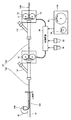
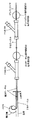
図1に示すように、本発明の実施の形態に係る線状体の引抜装置は、デリバリーワイヤ駆動部10と、子カテーテル駆動部20と、制御回路30とを備える。
As shown in FIG. 1, the linear body drawing apparatus according to the embodiment of the present invention includes a delivery
なお、本実施の形態においては、一例として、脳内の血管40にできた動脈瘤42のコイル塞栓術治療に用いられる医療器具としての引抜装置について説明する。なお、引抜装置の用途は動脈瘤42のコイル塞栓術治療に限らない。
In the present embodiment, as an example, a drawing device as a medical instrument used for the coil embolization treatment of the
コイル塞栓用の白金コイル100はデリバリーワイヤ110の先端に接続される。デリバリーワイヤ110とカテーテル120は、Yコネクタ131,132にそれぞれ挿入される。
The
カテーテル120は、親カテーテル122ならびに子カテーテル124を含む。親カテーテル122ならびに子カテーテル124は中空であり、子カテーテル124は親カテーテル122の中空部に挿入される。デリバリーワイヤ110は子カテーテル124の中空部に挿入される。
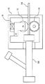
デリバリーワイヤ駆動部10はYコネクタ131の入口付近に設けられる。デリバリーワイヤ駆動部10は、図2に示すように、抑えローラ12と、送りローラ14と、モータ16とを含む。
The delivery
抑えローラ12ならびに送りローラ14は、抑えローラ12ならびに送りローラ14とでデリバリーワイヤ110を挟持するように設けられる。抑えローラ12は、図3に示すように、弾性体18により支持される。弾性体18の弾性力により、デリバリーワイヤ110を抑えローラ12ならびに送りローラ14とで挟持するために必要な力が付与される。
The
図2に戻って、送りローラ14はモータ16に連結される。なお、送りローラ14は、減速機などを介さずにモータ16のロータに直接連結される。モータ16は、定電流源140から供給される電流により駆動する。モータ16の駆動力、すなわち白金コイル100(デリバリーワイヤ110)を挿入もしくは引抜く力は、モータ16の電流値に応じて定まる。したがって、本実施の形態においては、モータ16の電流値を決定することにより、白金コイル100(デリバリーワイヤ110)を挿入もしくは引抜く力が決定される。
Returning to FIG. 2, the
送りローラ14の回転数(累積回転数)ならびに回転速度は、エンコーダ142により検出され、制御回路30に検出結果を表わす信号が入力される。さらに、制御回路30は、たとえば、送りローラ14の回転数に送りローラ14の円周を乗じることにより、デリバリーワイヤ110が引抜かれた長さを算出する。
The rotation speed (cumulative rotation speed) and rotation speed of the
子カテーテル駆動部20は、デリバリーワイヤ駆動部10と同様の構成を備える。子カテーテル駆動部20はYコネクタ132の入口付近に設けられる。
The child
制御回路30は、デリバリーワイヤ110および子カテーテル124を人体内に挿入するように、デリバリーワイヤ駆動部10および子カテーテル駆動部20を制御する。制御回路30には、医師などの操作に応じてデリバリーワイヤ110および子カテーテル124を挿入するようにデリバリーワイヤ駆動部10および子カテーテル駆動部20を制御するために、マスター機50が接続される。
The
マスター機50は、たとえばダイヤル式のデリバリーワイヤ操作部52と子カテーテル操作部54とを備える。制御回路30は、デリバリーワイヤ操作部52の回転量に応じた距離だけデリバリーワイヤ110を挿入(前進)ならびに後退するように、デリバリーワイヤ駆動部10を制御する。また、制御回路30は、子カテーテル操作部54の回転量に応じた距離だけ子カテーテル124を挿入ならびに後退するように、子カテーテル駆動部20を制御する。なお、医師などが手作業によりデリバリーワイヤ110および子カテーテル124を挿入するようにしてもよい。
The
さらに、制御回路30は、デリバリーワイヤ110および子カテーテル124を予め定められた力で引抜くように、デリバリーワイヤ駆動部10および子カテーテル駆動部20を制御する。
Further, the
制御回路30には、デリバリーワイヤ引抜ボタン32ならびに子カテーテル引抜ボタン34が接続される。デリバリーワイヤ引抜ボタン32がオン操作されると、制御回路30は、デリバリーワイヤ110を予め定められた力で引抜くように、デリバリーワイヤ駆動部10を制御する。子カテーテル引抜ボタン34がオン操作されると、制御回路30は、子カテーテル124を予め定められた力で引抜くように、子カテーテル駆動部20を制御する。
A delivery
これにより、適度な力で安全に、かつ容易にデリバリーワイヤ110および子カテーテル124を人体内から引抜くことができる。そのため、デリバリーワイヤ110および子カテーテル124を引抜く際に操作者に与える負担を軽減することができる。
Thereby, the
また、制御回路30は、デリバリーワイヤ110を引抜いた長さが予め定められた長さに達した場合、デリバリーワイヤ110の引抜きを停止するように、デリバリーワイヤ駆動部10を制御する。同様に、制御回路30は、子カテーテル124を引抜いた長さが予め定められた長さに達した場合、子カテーテル124の引抜きを停止するように、子カテーテル駆動部20を制御する。
In addition, the
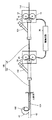
なお、図4に示すように、デリバリーワイヤ引抜ボタン32ならびに子カテーテル引抜ボタン34を、それぞれデリバリーワイヤ駆動部10ならびに子カテーテル駆動部20に設けるようにしてもよい。
As shown in FIG. 4, the delivery
また、デリバリーワイヤ110の代わりにもしくは加えて、カテーテル120を人体内に挿入する際に用いられる周知のガイドワイヤを引抜くようにしてもよい。また、子カテーテル124の代わりにもしくは加えて、親カテーテル122を引抜くようにしてもよい。
Further, instead of or in addition to the
さらに、引抜く長さが異なるように設定される複数の引抜きボタンを一つの線状体に対して設けるようにしてもよい。すなわち、複数の引抜ボタンのうち、操作される引抜ボタンに応じて線状体を引抜く長さが異なるようにしてもよい。 Furthermore, you may make it provide with respect to one linear body the several extraction button set so that the extraction length may differ. That is, the length for pulling out the linear body may be different among the plurality of pull-out buttons depending on the operated pull-out button.
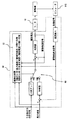
図5を参照して、制御回路30についてさらに説明する。制御回路30は、スイッチ60の接点を切替えることにより、デリバリーワイヤ110もしくは子カテーテル124を引抜く力を変更する。
The
スイッチ60の接点が「A」側にある場合、予め定められた一定の力でデリバリーワイヤ110もしくは子カテーテル124を引抜くように、デリバリーワイヤ駆動部10もしくは子カテーテル駆動部20が駆動される。
When the contact of the
スイッチ60の接点が「B」側にある場合、予め定められた最大速度でデリバリーワイヤ110もしくは子カテーテル124を引抜くように、デリバリーワイヤ駆動部10もしくは子カテーテル駆動部20が駆動される。
When the contact of the
スイッチ60の切替えは、制御切替器62により行なわれる。たとえば、デリバリーワイヤ110もしくは子カテーテル124を引抜くとき、デリバリーワイヤ110もしくは子カテーテル124の引抜抵抗が引抜く力と比較して極めて小さいと、デリバリーワイヤ110もしくは子カテーテル124が高速で引抜かれることになる。デリバリーワイヤ駆動部10もしくは子カテーテル駆動部20の送りローラの回転速度が速いと、デリバリーワイヤ110もしくは子カテーテル124の移動が追従できず、デリバリーワイヤ110もしくは子カテーテル124と送りローラとの間に滑りが発生し得る。
The
この場合、デリバリーワイヤ駆動部10もしくは子カテーテル駆動部20の送りローラ(あるいはモータ)と一体となって回転するエンコーダを使用した、デリバリーワイヤ110もしくは子カテーテル124の移動距離の計測ができなくなる。そのため、送りローラの回転は、線状体と送りローラとが滑らない速度に抑える必要がある。
In this case, it becomes impossible to measure the moving distance of the
そこで、制御切替器62は、デリバリーワイヤ駆動部10もしくは子カテーテル駆動部20の送りローラの回転速度、すなわちデリバリーワイヤ110もしくは子カテーテル124を引抜く速度が予め定められた最大速度よりも大きいと、スイッチ60の接点を「A」から「B」に切替える。
Therefore, when the rotation speed of the feed roller of the delivery
これにより、デリバリーワイヤ駆動部10もしくは子カテーテル駆動部20のモータに対して供給される駆動電流値が下げられ、デリバリーワイヤ110もしくは子カテーテル124を引抜く力が下げられる。そのため、線状体を送り出す送りローラと線状体との間で滑りがないようにすることができる。その結果、送りローラの回転数などから線状体を引抜いた長さを精度よく算出することができる。
Thereby, the drive current value supplied to the motor of the delivery
また、制御切替器62は、デリバリーワイヤ駆動部10もしくは子カテーテル駆動部20のモータに対して供給される駆動電流値が予め定められた電流値を超えると、すなわちデリバリーワイヤ110もしくは子カテーテル124を引抜く実際の力が、予め定められた力を超えると、スイッチ60の接点を「B」から「A」に切替える。これにより、デリバリーワイヤ110もしくは子カテーテル124を引抜く力を一定にすることができる。
In addition, the
なお、デリバリーワイヤ110が子カテーテル124の中側のみにあるときは、デリバリーワイヤ110を高速に引抜いても人体に傷をつける恐れが少ない。子カテーテル124が親カテーテル122の中に入っているときも同様である。
When the
また、上述した制御回路30の機能は、ソフトウェアにより実現するようにしてもよく、ハードウェアにより実現するようにしてもよい。
Further, the functions of the
今回開示された実施の形態は、すべての点で例示であって制限的なものではないと考えられるべきである。本発明の範囲は上記した説明ではなくて特許請求の範囲によって示され、特許請求の範囲と均等の意味および範囲内でのすべての変更が含まれることが意図される。 The embodiment disclosed this time should be considered as illustrative in all points and not restrictive. The scope of the present invention is defined by the terms of the claims, rather than the description above, and is intended to include any modifications within the scope and meaning equivalent to the terms of the claims.
10 デリバリーワイヤ駆動部、12 抑えローラ、14 送りローラ、16 モータ、18 弾性体、20 子カテーテル駆動部、30 制御回路、32 デリバリーワイヤ引抜ボタン、34 子カテーテル引抜ボタン、40 血管、42 動脈瘤、50 マスター機、52 デリバリーワイヤ操作部、54 子カテーテル操作部、60 スイッチ、62 制御切替器、100 白金コイル、110 デリバリーワイヤ、120 カテーテル、122 親カテーテル、124 子カテーテル、131,132 Yコネクタ、140 定電流源、142 エンコーダ。
DESCRIPTION OF
Claims (9)
操作者により操作される操作部と、
前記操作部が操作された場合、前記線状体を予め定められた力で引抜くように作動し、前記線状体を引抜く速度が予め定められた速度より大きい場合、前記線状体を引抜く力を下げ、前記線状体を引抜いた長さが予め定められた長さに達した場合、前記線状体の引抜きを停止するアクチュエータとを備える、線状体の引抜装置。 A medical linear body drawing device,
An operation unit operated by an operator;
When the operation unit is operated, the linear body is operated to be pulled out with a predetermined force, and when the speed of pulling out the linear body is higher than a predetermined speed, the linear body is An apparatus for extracting a linear body, comprising: an actuator that reduces an extraction force and stops the extraction of the linear body when a length of the linear body that has been extracted reaches a predetermined length.
前記操作部は複数設けられ、
前記アクチュエータは、前記複数の操作部のうちの、操作者により操作される操作部に応じて異なる線状体を引抜くように作動する、請求項1に記載の線状体の引抜装置。 There are a plurality of the linear bodies,
A plurality of the operation units are provided,
The linear body pulling device according to claim 1, wherein the actuator operates to pull out a different linear body according to an operation unit operated by an operator among the plurality of operation units.
前記アクチュエータは、前記複数の操作部のうちの、操作者により操作される操作部に応じて異なる長さだけ前記線状体を引抜くように作動する、請求項1に記載の線状体の引抜装置。 A plurality of the operation units are provided,
2. The linear body according to claim 1, wherein the actuator operates to pull out the linear body by a different length depending on an operation section operated by an operator among the plurality of operation sections. Drawing device.
前記アクチュエータは、前記送りローラを回転させることにより前記線状体を移動させる、請求項1〜3のいずれかに記載の線状体の引抜装置。 A feed roller and a holding roller that sandwich the linear body;
The linear actuator according to any one of claims 1 to 3, wherein the actuator moves the linear body by rotating the feed roller.
前記線状体を引抜いた長さは前記送りローラの回転数から算出される、請求項4または5に記載の線状体の引抜装置。 A detector for detecting the rotational speed of the feed roller;
The linear body drawing apparatus according to claim 4 or 5, wherein a length of drawing the linear body is calculated from a rotational speed of the feed roller.
前記送りローラは、前記モータに直接取り付けられる、請求項4〜6のいずれかに記載の線状体の引抜装置。 The actuator is a motor;
The linear body drawing device according to claim 4, wherein the feed roller is directly attached to the motor.
Priority Applications (4)
| Application Number | Priority Date | Filing Date | Title |
|---|---|---|---|
| JP2008140991A JP2009285151A (en) | 2008-05-29 | 2008-05-29 | Apparatus for drawing out linear member |
| PCT/JP2009/057062 WO2009125744A1 (en) | 2008-04-10 | 2009-04-06 | Linear object operation controller which controls operation of linear object by operator |
| US12/937,142 US20110028941A1 (en) | 2008-04-10 | 2009-04-06 | Linear object manipulation control device for controlling manipulation of linear object by operator |
| EP09730620.3A EP2266473B1 (en) | 2008-04-10 | 2009-04-06 | Linear object operation controller which controls operation of linear object by operator |
Applications Claiming Priority (1)
| Application Number | Priority Date | Filing Date | Title |
|---|---|---|---|
| JP2008140991A JP2009285151A (en) | 2008-05-29 | 2008-05-29 | Apparatus for drawing out linear member |
Publications (1)
| Publication Number | Publication Date |
|---|---|
| JP2009285151A true JP2009285151A (en) | 2009-12-10 |
Family
ID=41454940
Family Applications (1)
| Application Number | Title | Priority Date | Filing Date |
|---|---|---|---|
| JP2008140991A Withdrawn JP2009285151A (en) | 2008-04-10 | 2008-05-29 | Apparatus for drawing out linear member |
Country Status (1)
| Country | Link |
|---|---|
| JP (1) | JP2009285151A (en) |
Cited By (2)
| Publication number | Priority date | Publication date | Assignee | Title |
|---|---|---|---|---|
| JP5783904B2 (en) * | 2009-10-14 | 2015-09-24 | 国立大学法人 名古屋工業大学 | Insertion device and training device |
| EP2846707A4 (en) * | 2012-05-04 | 2016-11-30 | Interventco Llc | Device and method for filling of aneurysm or body cavity |
-
2008
- 2008-05-29 JP JP2008140991A patent/JP2009285151A/en not_active Withdrawn
Cited By (3)
| Publication number | Priority date | Publication date | Assignee | Title |
|---|---|---|---|---|
| JP5783904B2 (en) * | 2009-10-14 | 2015-09-24 | 国立大学法人 名古屋工業大学 | Insertion device and training device |
| EP2846707A4 (en) * | 2012-05-04 | 2016-11-30 | Interventco Llc | Device and method for filling of aneurysm or body cavity |
| US9549740B2 (en) | 2012-05-04 | 2017-01-24 | Interventco Llc | Device and method for filling of aneurysm or body cavity |
Similar Documents
| Publication | Publication Date | Title |
|---|---|---|
| JP5334035B2 (en) | Coil insertion device | |
| EP2542290B1 (en) | Robotic catheter system with variable drive mechanism | |
| WO2016194250A1 (en) | Medical manipulator system | |
| US6096004A (en) | Master/slave system for the manipulation of tubular medical tools | |
| EP2266473B1 (en) | Linear object operation controller which controls operation of linear object by operator | |
| JP5403785B2 (en) | Insertion device | |
| US11331119B2 (en) | Rotational medical device | |
| EP3111821A1 (en) | Slack correction mechanism, manipulator, and manipulator system | |
| WO2014010177A1 (en) | Force measurement device, force measurement method, master/slave device, force measurement program, and electronic integrated circuit | |
| WO2010143715A1 (en) | Medical control device | |
| JPWO2009069413A1 (en) | Drive device and medical device and training device provided with the same | |
| JP6837774B2 (en) | Catheter and guide wire interlocking insertion system | |
| JP2014004310A (en) | Medical instrument | |
| JP6192550B2 (en) | Medical device and medical system | |
| EP2953520A1 (en) | Robotic-assisted surgical system and control method thereof | |
| JP2009285151A (en) | Apparatus for drawing out linear member | |
| CN114191092A (en) | Interventional operation robot slave end delivery device | |
| US20180360551A1 (en) | Manipulator system and method for operating same | |
| EP3111868A1 (en) | Medical device, medical system, and mode transition method for medical device | |
| US10420573B2 (en) | Surgical tool | |
| EP3503818A1 (en) | Balloon catheter device for use in an aorta of a rabbit or a human being | |
| CN117529291A (en) | Compact robotic device and assembly for manipulating elongate surgical tools | |
| US20200108226A1 (en) | Medical device drive apparatus and force information calculation method | |
| JP2009273827A (en) | Linear object operation controller | |
| CN108367442A (en) | Effector system and its control method |
Legal Events
| Date | Code | Title | Description |
|---|---|---|---|
| A621 | Written request for application examination |
Free format text: JAPANESE INTERMEDIATE CODE: A621 Effective date: 20110426 |
|
| A761 | Written withdrawal of application |
Free format text: JAPANESE INTERMEDIATE CODE: A761 Effective date: 20121227 |