WO2011040499A1 - 機能内蔵コネクタ - Google Patents
機能内蔵コネクタ Download PDFInfo
- Publication number
- WO2011040499A1 WO2011040499A1 PCT/JP2010/067007 JP2010067007W WO2011040499A1 WO 2011040499 A1 WO2011040499 A1 WO 2011040499A1 JP 2010067007 W JP2010067007 W JP 2010067007W WO 2011040499 A1 WO2011040499 A1 WO 2011040499A1
- Authority
- WO
- WIPO (PCT)
- Prior art keywords
- connector
- female
- terminal
- male
- terminals
- Prior art date
- Legal status (The legal status is an assumption and is not a legal conclusion. Google has not performed a legal analysis and makes no representation as to the accuracy of the status listed.)
- Ceased
Links
Images


Classifications
-
- H—ELECTRICITY
- H01—ELECTRIC ELEMENTS
- H01R—ELECTRICALLY-CONDUCTIVE CONNECTIONS; STRUCTURAL ASSOCIATIONS OF A PLURALITY OF MUTUALLY-INSULATED ELECTRICAL CONNECTING ELEMENTS; COUPLING DEVICES; CURRENT COLLECTORS
- H01R13/00—Details of coupling devices of the kinds covered by groups H01R12/70 or H01R24/00 - H01R33/00
- H01R13/66—Structural association with built-in electrical component
- H01R13/665—Structural association with built-in electrical component with built-in electronic circuit
-
- H—ELECTRICITY
- H01—ELECTRIC ELEMENTS
- H01R—ELECTRICALLY-CONDUCTIVE CONNECTIONS; STRUCTURAL ASSOCIATIONS OF A PLURALITY OF MUTUALLY-INSULATED ELECTRICAL CONNECTING ELEMENTS; COUPLING DEVICES; CURRENT COLLECTORS
- H01R2107/00—Four or more poles
Definitions
- the present invention relates to a connector with a built-in function that accommodates a functional module and is connectable to a male terminal of the functional module.
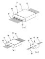
- FIG. 5 shows a form of a harness structure in which the conventional normal connector 51 of FIG. 5A is replaced by the function-incorporated connector 52 of FIG. 5B and the normal additional connector 53 of FIG. 5C. It is shown.
- the male connector 54 includes a connector housing made of an insulating resin having a connector fitting chamber 56 (represented by reference numeral 54), A plurality of male terminals (not shown) with electric wires 57 housed in the connector housing and projecting pin-shaped or tab-shaped electrical contact portions in the connector fitting chamber are formed.
- the connector housing is made of an insulating resin having a terminal housing chamber 58 (represented by reference numeral 55) and a female terminal (not shown) with an electric wire 59 housed in each terminal housing chamber 58.
- the male connector 54 has a male terminal and the female connector 55 has a female terminal.
- Electric wires 57 and 59 are connected to the male and female terminals by crimping or pressure welding.
- the electric wires 57 and 59 are insulation coated electric wires.
- the number of electric wires 57 led out from the male connector 54 is equal to the number of electric wires 59 led out from the female connector 55 (13 in this example).
- 5B includes a male connector 60 and a female connector 61.
- an electronic element (not shown) that functions as an IC, a microprocessor, or the like is built in the male connector 60.
- the electronic element exhibits a control function and the like, and can supply power to a load (not shown) such as a plurality of electrical components and devices of the vehicle and transfer signals by multiplex communication.
- a load such as a plurality of electrical components and devices of the vehicle and transfer signals by multiplex communication.
- the number of electric wires 63 on the female connector 61 side (7 in this example) is smaller than the number of electric wires 62 on the male connector 60 side (10 in this example).
- the normal additional connector 53 in FIG. 5C is used for wiring to supplement the power supply and communication to the vehicle load.
- the additional connector 53 includes a small male connector 64 and a female connector 65, and the configuration of the male / female connectors 64 and 65 is the same as that of the normal connector 51 shown in FIG. Three additional electric wires 66 and 67 are led out from the additional connector 53.
- the sum of the number of the electric wires 66 of the male connector 64 on the additional connector side (three) and the number of the electric wires 62 of the male connector 60 on the function built-in connector side (10) is the sum of the normal connector side in FIG.
- the number (13) of the electrical wires 59 of the female connector 55 on the normal connector side in FIG. 5A is equal to the number (13) of the electrical wires 57 of the male connector 54. This is larger than the sum of the number (7) of wires 63 of the female connector 61 and the number (3) of wires 67 of the female connector 65 on the additional connector side in FIG.
- Patent Document 1 describes a relay connector unit having a built-in communication relay device, and the communication relay device has signal address setting means (not shown).
- Patent Document 2 discloses a terminal arrangement of a connector connected to each load device in a configuration in which a control device and a plurality of load devices to be controlled are cable-connected, and a plurality of control signals and the like are transmitted using a common electric wire. It is described that the signal address of each load device is set using a pattern (not shown).
- the connector with a communication function includes a microcomputer inside the connector, so that the functions of the ECU, which has been conventionally intensively controlled, can be distributed in the connector, and multiplexing of signal lines can be performed. It is described that the function of the wire harness is simplified by the conversion (not shown).
- Patent Document 3 an IC is mounted on an insulating substrate, and a power line, a signal line, and a grant line following the load control ECU are connected to one terminal of the IC via a pressure contact terminal, and the other terminal of the IC is connected. It is described that a connector with a communication function is configured by connecting a female terminal to each terminal (not shown).
- Patent Document 4 describes that a power supply superposition multiplexing system that transmits signals without a dedicated communication line can be applied by superimposing communication on a power supply line (not shown).
- Japanese Unexamined Patent Publication No. 2008-293747 Japanese Unexamined Patent Publication No. 2005-285411 (paragraph number 2) Japanese Unexamined Patent Publication No. 2007-8261 (paragraph number 4, FIG. 1) Japanese Unexamined Patent Publication No. 2004-268630 (paragraph number 46)
- the present invention has an object to provide a connector with a built-in function that can cope with an increase in the number of connection circuits without using an additional connector.
- a connector with a built-in function is a connector housing in which a female terminal accommodating portion for accommodating a female terminal and a normal male terminal are arranged in two upper and lower stages.
- a functional module having a male terminal on the rear side and a male terminal on the front side connected to the male terminal on the rear side via an electronic element, and the functional module is mounted on the connector housing.
- the rear male terminal is connected to the female terminal, and the front male terminal is positioned in parallel with the normal male terminal.
- the normal male terminal and the female terminal are arranged in one connector housing, the male terminal on the rear side of the functional module is inserted and connected to the female terminal, and the male terminal on the front side of the functional module and the normal male terminal are connected.
- the function module has a control function and the like.
- the number of front terminals can be made smaller than the number of rear terminals to provide a multiplex communication circuit.
- a circuit serving as a conventional additional connector is configured by a normal male terminal, and a circuit serving as a conventional function built-in connector is configured by a functional module.
- the “normal male terminal” means a male terminal without an electronic element.
- the number of female terminals is two or more, the number of rear male terminals is the same as the number of female terminals, the number of front male terminals is one or more, and the number of normal male terminals is one or more. Preferably there is.
- the function built-in connector according to the second aspect of the present invention is the function built-in connector according to the first aspect, wherein the number of the front male terminals is smaller than the number of the rear male terminals.
- a multiplex communication circuit is formed by the control function of the equipment module, and the power and signals from the female terminal and the subsequent male terminal are multiplexed and communicated with the male terminal on the front side through the electronic elements, and the male terminal on the front side.
- the connector structure is made compact by reducing the number of terminals.
- the function built-in connector according to a third invention of the present invention is the function built-in connector according to the first or second invention, wherein an electric wire is connected to the normal male terminal and the female terminal, and the normal male terminal and the front side The female terminal of the mating connector is connected to the male terminal.
- each electric wire is connected to the normal male terminal and female terminal in the connector housing to form a connector for a wire harness.
- a general wire-to-wire connector is configured by connecting the female terminal of the mating connector to the electric wire.
- the electric wire is not limited to a round insulation-coated electric wire, and may be a flat electric wire.
- the flat electric wire constitutes a bendable flat harness.
- the additional connector can be provided with a function that cannot be substituted by the conventional function built-in connector by arranging the male terminal of the functional module and the normal male terminal not through the functional module at the same time. This eliminates the need for enlargement of the installation space, the increase in cost, and the increase in connector material due to the additional connector, and a space-saving, low-cost and environment-friendly connector structure can be obtained.
- the connector structure simpler and lighter by enabling the multiplex communication with the functional module and reducing the number of front male terminals for connection to the mating connector.
- the connector with a built-in function it is possible to enhance versatility by connecting the connector with a built-in function to an existing wire harness for vehicles.
- FIG.5 (a) is a perspective view which shows the conventional normal connector
- FIG.5 (b) is a conventional function
- FIG. 5C is a perspective view showing a conventional ordinary additional connector.
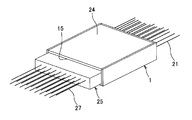
- FIG. 1 and 2 show an embodiment of a connector with a built-in function according to the present invention.
- the connector with a built-in function 1 includes a connector housing 2 and a function module 9.
- the connector housing 2 made of insulating resin includes a plurality of normal male terminals 3 disposed in the upper half of the connector housing 2, and a female terminal accommodating portion 4 disposed on the rear half of the lower half of the connector housing 2.
- the functional module 9 is disposed on the front half side of the lower half of the connector housing 2, the rear male terminals 6 connected to the female terminals 5 in the female terminal accommodating portion 4, and electronic elements or the like on the male terminals 6.
- Each male terminal 7 is connected to the front via a terminal (not shown).
- the direction in which the normal male terminals 3 and the female terminal accommodating portions 4 are arranged in two stages is the vertical direction, the direction in which the terminals are arranged is the horizontal direction, and the direction in which the male terminals 6 and 7 are located across the electronic element. Is the front-rear direction.
- the connector housing 2 is composed of right and left and rear vertical wall portions 10 and 11, a lower horizontal wall portion 12, and a lid wall 24 (FIG. 4) that closes the upper opening 13. It has a part opening 14 and an inner space 15 following the front opening 14.
- a female connector housing portion made of an insulating resin as a female terminal accommodating portion 4 is integrally provided at the lower stage of the connector housing 2 so as to intersect the rear half of the lower wall 12 and the left and right side walls 10 and the rear wall 11. .
- the horizontal upper wall 16 of the female terminal accommodating portion 4 is orthogonal to the intermediate portion in the height direction of the side wall 10 of the connector housing 2, and the vertical front wall 17 of the female terminal accommodating portion 4 is the lower wall 12 and both side walls of the connector housing 2. 10 is orthogonal.
- a plurality (10 in this example) of terminal accommodating chambers 18 are provided in parallel at an equal pitch, and each terminal accommodating chamber 18 has a male terminal insertion hole 19 in the front wall 17 and a connector housing 2.
- the rear wall 11 communicates with a rear opening (female terminal insertion port) 20.
- the male terminal insertion hole 19 is smaller than the rear opening 20, and the front end (front end) of the conductive metal female terminal 5 comes into contact with and stops at the inner surface of the front wall 17.
- Each female terminal 5 in the female terminal accommodating portion 4 has an electrical contact portion such as a rectangular tube in the first half and a wire connecting portion (crimping or pressure contacting portion) in the latter half, and the electrical contact portion is in the female terminal accommodating portion 4.
- Each electric wire (insulated coated electric wire) 21 which is locked by an insulating resin locking lance or spacer (not shown) and connected to the electric wire connecting portion is led out from the rear opening 20.
- a functional module housing space 15 a is located on the front side of the female terminal housing portion 4, and a male terminal housing space (represented by reference numeral 15) is located above the female terminal housing portion 4.
- a plurality of long pin-shaped normal male terminals 3 are arranged in parallel at equal pitches in the upper male terminal accommodating space 15.
- each normal male terminal 3 is fixed to the upper wall 16 of the female terminal accommodating portion 4 by insert molding, fitting into a groove (not shown), etc. 3, the electric wire (insulation-coated electric wire) 22 is shown as being connected by welding or the like.
- the upper wall 16 of the female terminal accommodating portion 4 is connected to the upper end (reference numeral 13 of both side walls 10 of the connector housing 2.
- a male terminal press-fitting hole (not shown) is provided to fix the normal male terminal 3, and each male terminal accommodating chamber (not shown) is provided in the extension.
- the latter half side of the normal male terminal 3 may be accommodated, and the electric wire 22 may be connected by providing an electric wire connecting portion (crimping portion or press contact portion) at the rear portion of the normal male terminal 3.
- the electric wire 22 connected to each normal male terminal 3 passes through the hole 23 of the rear wall 11 of the connector housing 2 and is led out to the outside.
- Each normal male terminal 3 is used to connect a normal circuit.
- the number of normal male terminals 3 in this example is eight.
- Each normal male terminal 3 passes horizontally through the space 15 above the functional module housing space 15 a, and the tip (front end) 3 a of each normal male terminal 3 is positioned in front of the front opening 14 of the connector housing 2.
- Each ordinary male terminal 3 in this example has a rectangular cross section, but may have a circular cross section.
- the functional module 9 is arranged in the space 15a below each normal male terminal 3.
- the functional module 9 is composed of a functional unit body (represented by reference numeral 8) in which various electronic elements (not shown) forming an IC, a microprocessor, and the like are accommodated and insulated in a plate-shaped insulating resin body 8, and an insulating resin body. 8, each pin is connected to each electronic element, and is composed of front and rear short pin-like male terminals 6 and 7 protruding outward from front and rear end portions 8 a and 8 b of the insulating resin body 8.
- 10 rear male terminals 6 are arranged in parallel at an equal pitch
- 7 front male terminals 7 are arranged in parallel at an equal pitch
- the pitches of the front and rear male terminals 6 and 7 are equal. Since the front male terminal 7 is connected to the rear male terminal 6 via an electronic element or the like, the number of front male terminals 7 is increased by the multiplex communication (the male terminal 7 is shared). The number has been reduced.
- the pitch of the front male terminal 7 is equal to the pitch of the upper normal male terminal 3.
- the pitch of the rear male terminals 6 is equal to the pitch of the female terminals 5.
- the protruding lengths of the front and rear male terminals 6 and 7 in this example are the same as or slightly shorter than the length of the insulating resin body 8 in the front-rear direction.
- the functional module 9 is inserted into the lower space 15a from the front opening 14 of the connector housing 2 as indicated by an arrow, and each terminal 6 on the rear side of the functional module 9 is connected to the front wall of the female terminal accommodating portion 4 of the connector housing 2. 17 is inserted into the female terminal accommodating portion 4 from the hole 19 and connected to each female terminal 5 in the terminal accommodating chamber 18.
- the insulating resin body 8 of the functional module 9 is locked to the left and right side walls 10 of the connector housing 2 by locking means (not shown) such as protrusions, arms, or recesses.
- each upper normal male terminal 3 is connected to the functional module. 9 is inserted into the male terminal accommodating chamber in the extension (not shown) on the female terminal accommodating portion 4 and locked with a locking lance (not shown) in the male terminal accommodating chamber, Or press-fit into the hole.
- the upper and lower male terminals 3, 7 are connected to the connector housing 2 with the rear female terminal 5 (FIG. 1), the upper normal male terminal 3, and the lower functional module 9 assembled.
- the tips (front ends) 3 a and 7 a of the upper and lower male terminals 3 and 7 are positioned in parallel at the same pitch, and are positioned on the same virtual vertical plane before the front opening 14 of the connector housing 2.
- a cover wall 24 (FIG. 4) is attached to the upper opening 13 of the connector housing 2, and between the cover wall (upper wall) 24 and each upper normal male terminal 3 and between the lower wall 12 and the lower wall. A similar gap is formed between the male terminal 7 and the male terminal 7.
- the lid wall 24 is locked to both side walls 10 of the connector housing 2 by locking means (not shown) such as a frame piece and a protrusion, a protrusion and a recess, or the like.
- the function built-in connector 1 of FIG. 2 can also be called a male / female terminal mixed connector.
- FIG. 3 shows one form of a normal counterpart female connector 25 on the counterpart side with respect to the function built-in connector 1 of FIG.
- the mating female connector 25 includes a connector housing 26 made of an insulating resin having a plurality of terminal housing chambers 29 in two upper and lower stages and in parallel on the left and right sides, and a female terminal 30 with an electric wire 27 inserted into each terminal housing chamber 29. It consists of and.
- a hole (not shown) through which the upper and lower male terminals 3 and 7 of the connector with built-in function 1 of FIG. 2 are inserted is provided in the front wall 28 of the connector housing 26 so as to communicate with the terminal accommodating chambers 29. 26 has a rear opening 32 for inserting a female terminal larger than the hole.
- the upper ten electric wires 27 and the lower nine electric wires 27 are led out from the mating female connector 25 of this example, but the number of the electric wires 27 and the number of the respective female terminals 30 can be set as appropriate. . Further, two of the upper ten female terminals 30 of the mating female connector 25 of FIG. (Not shown), the other female terminals 30 are jointed, and the nine female terminals 7 on the lower side of the mating female connector 25 in FIG. Two of the terminals 30 can be joined to other female terminals 30 by short-circuit terminals (not shown), so that the number of wires in each of the connectors 1 and 25 in FIGS.
- the mating female connector 25 is inserted and fitted into the connector fitting chamber 15 of the function built-in connector 1.
- the upper and lower male terminals 3 and 7 (FIG. 2) and the upper and lower female terminals 30 (FIG. 3) of the mating female connector 25 are inserted and connected.
- the front wall 28 (FIG. 3) of the mating female connector 25 comes into contact with the front wall 17 of the female terminal accommodating portion 4 which is the bottom of the connector fitting chamber 15 of FIG.
- the lower function module 9 performs the function of the conventional function built-in connector of FIG. 5B, and the function of the additional connector of FIG.
- space saving and cost reduction can be achieved with one function-incorporated connector 1 and materials (resin material forming the connector housing of the additional connector shown in FIG. 5C and metal material forming the terminal) can be reduced. Can do.
- the functional module 9 is arranged at the lower stage of the connector housing 2 and the normal male terminal 3 is arranged at the upper stage.
- the functional module 9 is arranged at the upper stage of the connector housing 2. It is also possible to arrange a normal male terminal 3 in the lower stage.
- the electric wires 21 and 22 were respectively connected to the normal male terminal 3 and the female terminal 5, it replaces with the electric wires 21 and 22 and is electrically conductive to the normal male terminal 3 and / or the female terminal 5. It is also possible to connect or integrally form a metal plate bus bar (not shown). Moreover, it is also possible to use the flat type electric wire (not shown) which comprises a flat harness instead of a round insulation coating electric wire as the electric wires 21 and 22.
- the connector with a built-in function according to the present invention can be used when it is necessary to mix a circuit for multiplex communication and a normal circuit in response to, for example, addition of an optional part or upgrade of an automobile.
Landscapes
- Engineering & Computer Science (AREA)
- Microelectronics & Electronic Packaging (AREA)
- Details Of Connecting Devices For Male And Female Coupling (AREA)
- Connector Housings Or Holding Contact Members (AREA)
- Coupling Device And Connection With Printed Circuit (AREA)
Abstract
付加コネクタを用いることなく、接続回路数の増加に対応できるようにする。 コネクタハウジング(2)内に雌端子収容部(4)と通常の雄端子(3)とが上下二段に配設され、雌端子収容部に雌端子(5)が収容され、雌端子に接続する後側の雄端子(6)と、後側の雄端子に電子素子を介して接続する前側の雄端子(7)とを有する機能モジュール(9)がコネクタハウジング内に装着され、前側の雄端子(7)が通常の雄端子(3)と平行に位置する機能内蔵コネクタ(1)を採用する。前側の雄端子(7)の数を後側の雄端子(6)の数よりも少なくした。通常の雄端子(3)と雌端子(5)とに電線(21,22)を接続し、通常の雄端子と前側の雄端子(7)とに相手側雌コネクタ(25)の雌端子(30)を接続する。
Description
本発明は、機能モジュールを収容するとともに、その機能モジュールの雄端子に接続可能とした機能内蔵コネクタに関するものである。
図5は、図5(a)の従来の通常のコネクタ51を、図5(b)の機能内蔵コネクタ52と図5(c)の通常の付加コネクタ53とによって代行したハーネス構造の一形態を示すものである。
図5(a)の通常のコネクタ51は、雄コネクタ54と雌コネクタ55とで構成され、雄コネクタ54は、コネクタ嵌合室56を有する絶縁樹脂製のコネクタハウジング(符号54で代用)と、コネクタハウジング内に収容され、コネクタ嵌合室内にピン状ないしタブ状の電気接触部を突出させた電線57付きの複数の雄端子(図示せず)とで構成され、雌コネクタ55は、複数の端子収容室58を有する絶縁樹脂製のコネクタハウジング(符号55で代用)と、各端子収容室58に収容された電線59付きの雌端子(図示せず)とで構成されている。
本明細書では、雄コネクタ54は雄端子を有し、雌コネクタ55は雌端子を有するものとして説明する。雄、雌の各端子には電線57,59が圧着又は圧接等で接続されている。電線57,59は絶縁被覆電線である。雄コネクタ54から導出される電線57の本数と雌コネクタ55から導出される電線59の本数は等しい(本例では各13本である)。
図5(b)の機能内蔵コネクタ52は、雄コネクタ60と雌コネクタ61とで成るが、本例では雄コネクタ60内に機能としてICやマイクロプロセッサ等をなす電子素子(図示せず)が内蔵されている。電子素子は制御機能等を発揮し、車両の複数の電装品や機器等の負荷(図示せず)に対する給電や信号の授受を多重通信で行わせることができる。このため、雌コネクタ61側の電線63の本数(本例で7本)が雄コネクタ60側の電線62の本数(本例で10本)に較べて少なくなっている。
この機能内蔵コネクタ52のみでは代行できないシステムがある場合に、図5(c)の通常の付加コネクタ53を配線に用いて、車両の負荷への給電や通信を補っている。付加コネクタ53は小さな雄コネクタ64と雌コネクタ65とで成り、雄・雌コネクタ64,65の構成は図5(a)の通常のコネクタ51を小型化したものと同じである。付加コネクタ53からは各3本の電線66,67が導出されている。
付加コネクタ側の雄コネクタ64の電線66の本数(3本)と機能内蔵コネクタ側の雄コネクタ60の電線62の本数(10本)との総和は、図5(a)の通常のコネクタ側の雄コネクタ54の電線57の本数(13本)に等しく、図5(a)の通常のコネクタ側の雌コネクタ55の電線59の本数(13本)は、図5(b)の機能内蔵コネクタ側の雌コネクタ61の電線63の本数(7本)と図5(c)の付加コネクタ側の雌コネクタ65の電線67の本数(3本)との総和よりも多い。
上記以外の機能内蔵コネクタを用いたハーネス構造としては、例えば特許文献1に、通信中継装置を内蔵した中継コネクタユニットが記載され、通信中継装置は信号アドレス設定手段を有しており(図示せず)、特許文献2には、制御装置と制御対象の複数の負荷装置とをケーブル接続し、電線を共用して複数の制御信号等を伝送する構成において、各負荷装置に接続するコネクタの端子配置パターンを用いて各負荷装置の信号アドレスの設定を行うことが記載されている(図示せず)。
また、特許文献3には、通信機能付きコネクタがコネクタ内部にマイクロコンピュータを備えることにより、従来集中的な制御を行っていたECUの機能をコネクタ内に分散させることができると共に、信号線の多重化によってワイヤハーネスの機能も簡素になることが記載されている(図示せず)。
同じく特許文献3には、絶縁基板にICを搭載し、ICの一方の各端子に圧接端子を介して負荷制御用ECUに続く電源線と信号線とグラント線とを接続し、ICの他方の各端子に雌端子を接続して、通信機能付コネクタを構成したことが記載されている(図示せず)。また、特許文献4には、電源線の通信を重畳させることで、専用通信線なしで信号を伝送する電源重畳多重方式を適用可能であることが記載されている(図示せず)。
しかしながら、上記従来の図5の機能内蔵コネクタ52とそれを用いたハーネス構造にあっては、機能内蔵コネクタ52で代用できない機能(接続回路数の補強)を別の付加コネクタ53で補わなければならないために、付加コネクタ53の分の材料やコストや設置スペースが増えて、例えば材料増加による環境問題を生じかねない等の懸念があった。
本発明は、上記した点に鑑み、付加コネクタを用いることなく、接続回路数の増加に対応することのできる機能内蔵コネクタを提供することを目的とする。
上記目的を達成するために、本発明の第1発明に係る機能内蔵コネクタは、雌端子が収容される雌端子収容部と、通常の雄端子と、が上下二段に配設されたコネクタハウジングと、後側の雄端子と、該後側の雄端子に電子素子を介して接続する前側の雄端子と、を有する機能モジュールと、を備え、前記機能モジュールが前記コネクタハウジングに装着された際、前記後側の雄端子が前記雌端子に接続されるとともに、前記前側の雄端子が前記通常の雄端子と平行に位置する。
上記構成により、一つのコネクタハウジング内に通常の雄端子と雌端子とが配置され、雌端子に機能モジュールの後側の雄端子が挿入接続され、機能モジュールの前側の雄端子と通常の雄端子とが平行に位置して、相手側コネクタの各雌端子に同時に接続可能となる。機能モジュールは制御機能等を有する。これにより、例えば前側の端子の数を後側の端子の数よりも減少させて多重通信回路とすることができる。通常の雄端子で従来の付加コネクタの役割の回路が構成され、機能モジュールで従来の機能内蔵コネクタの役割の回路が構成される。「通常の雄端子」とは電子素子を介さない雄端子の意味である。雌端子の数は二つ以上であり、後側の雄端子の数は雌端子と同数であり、前側の雄端子の数は一つ以上であり、通常の雄端子の数は一つ以上であることが好ましい。
本発明の第2発明に係る機能内蔵コネクタは、第1発明の機能内蔵コネクタにおいて、前記前側の雄端子の数が前記後側の雄端子の数よりも少ない。
上記構成により、機器モジュールの制御機能によって多重通信回路が形成され、雌端子とそれに続く後側の雄端子からの電源や信号等が電子素子を経て前側の雄端子で多重通信され、前側の雄端子の数の減少によってコネクタ構造がコンパクト化される。
本発明の第3発明に係る機能内蔵コネクタは、第1発明又は第2発明の機能内蔵コネクタにおいて、前記通常の雄端子と前記雌端子とに電線が接続され、該通常の雄端子と前記前側の雄端子とに相手側コネクタの雌端子が接続される。
上記構成により、コネクタハウジング内の通常の雄端子と雌端子とに各電線が接続されてワイヤハーネス用のコネクタが構成される。相手側コネクタの雌端子をも電線に接続することで、一般的なワイヤtoワイヤコネクタが構成される。電線は丸型絶縁被覆電線に限らずフラット電線とすることも可能である。フラット電線は屈曲自在なフラットハーネスを構成する。
本発明の第1発明によれば、機能モジュールの雄端子と機能モジュールを介さない通常の雄端子とを同時に配設したことで、従来の機能内蔵コネクタでは代行できない機能を付加コネクタに担わせることが不要となり、付加コネクタに起因する取付スペースの肥大化やコストの増加やコネクタ材料の増加が解消されて、省スペースで低コスト且つ環境に優しいコネクタ構造を得ることができる。
本発明の第2発明によれば、機能モジュールで多重通信を可能として、相手側コネクタに対する接続用の前側の雄端子を減少させて、コネクタ構造を簡素化・軽量化することができる。
本発明の第3発明によれば、車両用の既存のワイヤハーネスに機能内蔵コネクタを接続して、汎用性を高めることができる。
図1~図2は、本発明に係る機能内蔵コネクタの一実施形態を示すものである。
図1の如く、この機能内蔵コネクタ1は、コネクタハウジング2と、機能モジュール9と、により構成される。絶縁樹脂製のコネクタハウジング2は、コネクタハウジング2の上半部に配置された複数の通常の雄端子3と、コネクタハウジング2の下半部の後半側に配設された雌端子収容部4と、を有する。機能モジュール9は、コネクタハウジング2の下半部の前半側に配置され、雌端子収容部4内の各雌端子5に接続される後部の各雄端子6と、各雄端子6に電子素子等(図示せず)を介して接続される前部の各雄端子7とを有する。尚、通常の雄端子3と雌端子収容部4が二段に並ぶ方向を上下方向とし、各端子が並ぶ方向を左右方向とし、電子素子を挟んで雄端子6及び雄端子7が位置する方向を前後方向とする。
コネクタハウジング2は、左右と後側の垂直な各壁部10,11と下側の水平な壁部12と、上部開口13を塞ぐ蓋壁24(図4)とで構成され、長方形状の前部開口14と、前部開口14に続く内側の空間15とを有している。下壁12と左右の側壁10との後半側と後壁11とにそれぞれ交差して雌端子収容部4としての絶縁樹脂製の雌コネクタハウジング部がコネクタハウジング2の下段に一体に設けられている。
雌端子収容部4の水平な上壁16はコネクタハウジング2の側壁10の高さ方向中間部に直交し、雌端子収容部4の垂直な前壁17はコネクタハウジング2の下壁12と両側壁10とに直交している。雌端子収容部4内には複数(本例で10個)の端子収容室18が等ピッチで並列に設けられ、各端子収容室18は前壁17の雄端子挿入孔19とコネクタハウジング2の後壁11の後部開口(雌端子挿入口)20とに連通している。雄端子挿入孔19は後部開口20よりも小さく、前壁17の内面に導電金属製の雌端子5の先端(前端)が当接停止する。
雌端子収容部4内の各雌端子5は前半の矩形筒状等の電気接触部と後半の電線接続部(圧着又は圧接部)とを有し、電気接触部が雌端子収容部4内の絶縁樹脂製の係止ランス又はスペーサ(図示せず)で係止され、電線接続部に接続された各電線(絶縁被覆電線)21が後部開口20から外部に導出されている。
コネクタハウジング2内で雌端子収容部4の前側に機能モジュール収容空間15aが位置し、雌端子収容部4の上側に雄端子収容空間(符号15で代用)が位置している。上側の雄端子収容空間15に複数のピン状の長い通常の雄端子3が等ピッチで並列に配設されている。
図1の例では、雌端子収容部4の上壁16に各通常の雄端子3の後端部をインサート成形や溝(図示せず)への嵌合等で固定し、各通常の雄端子3の後端部に電線(絶縁被覆電線)22を溶接等で接続したものとして示しているが、例えば、雌端子収容部4の上壁16をコネクタハウジング2の両側壁10の上端(符号13で代用)まで高く延長し、その延長部内に雄端子圧入孔(図示せず)を設けて通常の雄端子3を圧入固定したり、延長部内に各雄端子収容室(図示せず)を設けて通常の雄端子3の後半側を収容し、通常の雄端子3の後部に電線接続部(圧着部又は圧接部)を設けて電線22を接続する等してもよい。何れの場合も各通常の雄端子3に接続した電線22はコネクタハウジング2の後壁11の孔部23を貫通して外部に導出される。
各通常の雄端子3は通常の回路の接続に使用される。本例の通常の雄端子3の数は8本である。各通常の雄端子3は機能モジュール収容空間15aの上側の空間15を水平に通り、各通常の雄端子3の先端(前端)3aはコネクタハウジング2の前部開口14の手前に位置している。本例の各通常の雄端子3の断面は矩形状であるが、断面円形であってもよい。
各通常の雄端子3の下側の空間15aに機能モジュール9が配置される。機能モジュール9はICやマイクロプロセッサ等をなす各種の電子素子(図示せず)を板状の絶縁樹脂体8の内部に収容絶縁して成る機能部本体(符号8で代用)と、絶縁樹脂体8内で各電子素子に接続され、絶縁樹脂体8の前後の各端部8a,8bから外部に突出した前後の短いピン状の各雄端子6,7とで構成されている。
本例で後側の雄端子6は10本並列に等ピッチで配置され、前側の雄端子7は7本並列に等ピッチで配置され、前後の各雄端子6,7のピッチは等しい。前側の雄端子7は電子素子等を経て後側の雄端子6に接続しているので、多重通信化(雄端子7の共用化)によって前側の雄端子7の本数が後側の雄端子6の本数よりも削減されている。前側の雄端子7のピッチは上側の通常の雄端子3のピッチと等しい。後側の雄端子6のピッチは雌端子5のピッチと等しい。本例の前後の雄端子6,7の突出長さは絶縁樹脂体8の前後方向長さと同程度かそれよりも少し短い。
機能モジュール9を矢印の如くコネクタハウジング2の前部開口14から下側の空間15aに挿着しつつ、機能モジュール9の後側の各端子6をコネクタハウジング2の雌端子収容部4の前壁17の孔部19から雌端子収容部4内に挿入して、端子収容室18内の各雌端子5に接続させる。機能モジュール9の絶縁樹脂体8はコネクタハウジング2の左右の側壁10に突起やアームや凹部等といった係止手段(図示せず)で係止される。
コネクタハウジング2への機能モジュール9の組付は、上側の通常の長い通常の雄端子3を装着する前に行うことも可能であり、その場合、上側の各通常の雄端子3は、機能モジュール9の装着後に、雌端子収容部4上の延長部内(図示せず)の雄端子収容室に挿入して、雄端子収容室内の係止ランス(図示せず)で係止したり、延長部内の孔部に圧入固定したりする。
図2の如く、コネクタハウジング2に後半側の雌端子5(図1)と上側の通常の雄端子3と下側の機能モジュール9とを組み付けた状態で、上下の各雄端子3,7は同ピッチで平行に位置し、上下の各雄端子3,7の先端(前端)3a,7aはコネクタハウジング2の前部開口14の手前で垂直な仮想の同一面上に位置する。
コネクタハウジング2の上部開口13には蓋壁24(図4)が被着され、蓋壁(上壁)24と上側の長い各通常の雄端子3との間と、下壁12と下側の雄端子7との間とに同程度の隙間が形成される。蓋壁24はコネクタハウジング2の両側壁10に枠片と突起、突起と凹部等といった係止手段(図示せず)で係止される。図2の機能内蔵コネクタ1は雄雌端子混在コネクタとも呼称することができる。
図3は、図2の機能内蔵コネクタ1に対する相手側の通常の相手側雌コネクタ25の一形態を示すものである。相手側雌コネクタ25は、複数の端子収容室29を上下二段に且つ左右に並列に有する絶縁樹脂製のコネクタハウジング26と、各端子収容室29内に挿入された電線27付きの雌端子30とで構成されている。
各端子収容室29に連通してコネクタハウジング26の前壁28には図2の機能内蔵コネクタ1の上下の各雄端子3,7を挿入させる孔部(図示せず)が設けられ、コネクタハウジング26の後壁31には孔部よりも大きな雌端子挿入用の後部開口32が設けられている。
本例の相手側雌コネクタ25からは上段の10本の電線27と下段の9本の電線27とが導出されているが、電線27の本数や各雌端子30の数は適宜設定可能である。また、図2の機能内蔵コネクタ1の上段の8本の通常の雄端子3に対して、図3の相手側雌コネクタ25の上段の10本の雌端子30のうちの2本を短絡端子(図示せず)で他の雌端子30にジョイントさせたり、図2の機能内蔵コネクタ1の下段の7本の雄端子7に対して、図3の相手側雌コネクタ25の上段の9本の雌端子30のうちの2本を短絡端子(図示せず)で他の雌端子30にジョイントさせて、図2,図3の各コネクタ1,25の電線本数を同一とすることも可能である。
図4に、機能内蔵コネクタ1を用いたハーネス構造の一形態を示す如く、機能内蔵コネクタ1のコネクタ嵌合室15内に相手側雌コネクタ25を挿入嵌合させることで、機能内蔵コネクタ1の上下の雄端子3,7(図2)と相手側雌コネクタ25の上下の雌端子30(図3)とが挿入接続される。相手側雌コネクタ25の前壁28(図3)は図2のコネクタ嵌合室15の底部である雌端子収容部4の前壁17に当接して停止する。
なお、図2の機能内蔵コネクタ1の前後と図3の相手側雌コネクタ25の前後とはそれぞれのコネクタの嵌合面14,28側を前として説明しているが、機能内蔵コネクタ1の方向に合わせて相手側雌コネクタ25の前壁28を後壁と呼称してもよい。
上記機能内蔵コネクタ1によれば、従来の図5(b)の機能内蔵コネクタの機能を下側の機能モジュール9が果たし、図5(c)の付加コネクタの機能を上側の通常の雄端子3が果たすことで、一つの機能内蔵コネクタ1で省スペース化と低コスト化と材料(図5(c)の付加コネクタのコネクタハウジングを成す樹脂材料や端子を成す金属材料)の削減とを図ることができる。
なお、上記実施形態においては、コネクタハウジング2の下段に機能モジュール9を配置し、上段に通常の雄端子3を配置したが、これとは逆にコネクタハウジング2の上段に機能モジュール9を配置し、下段に通常の雄端子3を配置することも可能である。
また、上記実施形態においては、通常の雄端子3と雌端子5とにそれぞれ電線21,22を接続したが、電線21,22に代えて、通常の雄端子3及び/又は雌端子5に導電金属板状のバスバー(図示せず)を接続ないし一体に形成することも可能である。また、電線21,22として丸型絶縁被覆電線に代えてフラットハーネスを成す平型電線(図示せず)を用いることも可能である。
本発明に係る機能内蔵コネクタは、例えば自動車のオプション部品の追加やグレードアップ等に対応して、多重通信用の回路と通常の回路とを混在させる必要がある場合に利用することができる。
本発明を詳細にまた特定の実施態様を参照して説明したが、本発明の精神と範囲を逸脱することなく様々な変更や修正を加えることができることは当業者にとって明らかである。
本出願は、2009年10月1日出願の日本特許出願(特願2009-229515)に基づくものであり、その内容はここに参照として取り込まれる。
1 機能内蔵コネクタ
2 コネクタハウジング
3 通常の雄端子
4 雌端子収容部
5 雌端子
6 後側の雄端子
7 前側の雄端子
9 機能モジュール
21,22 電線
25 相手側雌コネクタ
2 コネクタハウジング
3 通常の雄端子
4 雌端子収容部
5 雌端子
6 後側の雄端子
7 前側の雄端子
9 機能モジュール
21,22 電線
25 相手側雌コネクタ
Claims (3)
- 雌端子が収容される雌端子収容部と、通常の雄端子と、が上下二段に配設されたコネクタハウジングと、
後側の雄端子と、該後側の雄端子に電子素子を介して接続する前側の雄端子と、を有する機能モジュールと、
を備え、
前記機能モジュールが前記コネクタハウジングに装着された際、前記後側の雄端子が前記雌端子に接続されるとともに、前記前側の雄端子が前記通常の雄端子と平行に位置する機能内蔵コネクタ。 - 前記前側の雄端子の数が前記後側の雄端子の数よりも少ない請求項1記載の機能内蔵コネクタ。
- 前記通常の雄端子と前記雌端子とに電線が接続され、該通常の雄端子と前記前側の雄端子とに相手側コネクタの雌端子が接続される請求項1又は2記載の機能内蔵コネクタ。
Applications Claiming Priority (2)
| Application Number | Priority Date | Filing Date | Title |
|---|---|---|---|
| JP2009229515A JP5467835B2 (ja) | 2009-10-01 | 2009-10-01 | 機能内蔵コネクタ |
| JP2009-229515 | 2009-10-01 |
Publications (1)
| Publication Number | Publication Date |
|---|---|
| WO2011040499A1 true WO2011040499A1 (ja) | 2011-04-07 |
Family
ID=43826311
Family Applications (1)
| Application Number | Title | Priority Date | Filing Date |
|---|---|---|---|
| PCT/JP2010/067007 Ceased WO2011040499A1 (ja) | 2009-10-01 | 2010-09-29 | 機能内蔵コネクタ |
Country Status (2)
| Country | Link |
|---|---|
| JP (1) | JP5467835B2 (ja) |
| WO (1) | WO2011040499A1 (ja) |
Cited By (1)
| Publication number | Priority date | Publication date | Assignee | Title |
|---|---|---|---|---|
| CN113130329A (zh) * | 2020-01-15 | 2021-07-16 | 王常亮 | 一种ic封装体单排直列伸出引脚的多向引出方法及应用该方法制得的功率集成电路部件 |
Families Citing this family (1)
| Publication number | Priority date | Publication date | Assignee | Title |
|---|---|---|---|---|
| JP2021079946A (ja) * | 2021-02-16 | 2021-05-27 | 株式会社ユピテル | 物 |
Citations (2)
| Publication number | Priority date | Publication date | Assignee | Title |
|---|---|---|---|---|
| WO2008072442A1 (ja) * | 2006-12-11 | 2008-06-19 | Autonetworks Technologies, Ltd. | 分岐コネクタ |
| JP2008226809A (ja) * | 2007-02-16 | 2008-09-25 | Yazaki Corp | 電子部品内蔵コネクタ |
Family Cites Families (2)
| Publication number | Priority date | Publication date | Assignee | Title |
|---|---|---|---|---|
| JPS611284U (ja) * | 1984-06-08 | 1986-01-07 | 松下電工株式会社 | ヒユ−ズ装着付きコネクタ |
| JP2001291558A (ja) * | 2000-04-06 | 2001-10-19 | Yazaki Corp | 電子部品内蔵コネクタ |
-
2009
- 2009-10-01 JP JP2009229515A patent/JP5467835B2/ja not_active Expired - Fee Related
-
2010
- 2010-09-29 WO PCT/JP2010/067007 patent/WO2011040499A1/ja not_active Ceased
Patent Citations (2)
| Publication number | Priority date | Publication date | Assignee | Title |
|---|---|---|---|---|
| WO2008072442A1 (ja) * | 2006-12-11 | 2008-06-19 | Autonetworks Technologies, Ltd. | 分岐コネクタ |
| JP2008226809A (ja) * | 2007-02-16 | 2008-09-25 | Yazaki Corp | 電子部品内蔵コネクタ |
Cited By (1)
| Publication number | Priority date | Publication date | Assignee | Title |
|---|---|---|---|---|
| CN113130329A (zh) * | 2020-01-15 | 2021-07-16 | 王常亮 | 一种ic封装体单排直列伸出引脚的多向引出方法及应用该方法制得的功率集成电路部件 |
Also Published As
| Publication number | Publication date |
|---|---|
| JP5467835B2 (ja) | 2014-04-09 |
| JP2011076971A (ja) | 2011-04-14 |
Similar Documents
| Publication | Publication Date | Title |
|---|---|---|
| JP5378938B2 (ja) | 機能内蔵コネクタを用いたハーネス接続構造 | |
| CN101142721B (zh) | 电气设备 | |
| JP5031599B2 (ja) | 通信線用の分岐コネクタ | |
| JP4408826B2 (ja) | 電気回路基板収容箱 | |
| US8118601B2 (en) | Printed circuit board plug-type connector and connection module with printed circuit board plug-type connector | |
| JP5221026B2 (ja) | 電子ユニットの組立方法 | |
| CN100438720C (zh) | 用于车辆的集成电模块结构 | |
| JP5467835B2 (ja) | 機能内蔵コネクタ | |
| CN108174621B (zh) | 连接器单元、装入电气部件的连接器以及带连接器的电气部件 | |
| JP2009266603A (ja) | アースジョイントコネクタ | |
| JP5128179B2 (ja) | 電気接続箱 | |
| JP5227864B2 (ja) | 通信中継装置及び通信中継コネクタ | |
| KR20120018843A (ko) | 자동차용 정션박스 | |
| JP2987539B2 (ja) | バスバー付コネクタ | |
| CN223713181U (zh) | 板端连接器、线端连接器及车辆 | |
| JP6656017B2 (ja) | 制御基板及び電気接続箱 | |
| KR20190137024A (ko) | 양방향 조인트 커넥터 | |
| JP7261130B6 (ja) | ワイヤーハーネス接続用モジュールおよび電装システム | |
| JP3317627B2 (ja) | コネクタ及びコネクタ付電子ユニット | |
| JP3085207B2 (ja) | 電気接続箱 | |
| CN101562286A (zh) | 电连接器组件 | |
| CN218483027U (zh) | 一种拓展板和具有该拓展板的电路组件、电子设备 | |
| JP3652554B2 (ja) | 電気接続箱 | |
| CN107618458B (zh) | 连接器以及内部信号回路端子 | |
| JP2012059473A (ja) | コネクタの接続構造 |
Legal Events
| Date | Code | Title | Description |
|---|---|---|---|
| 121 | Ep: the epo has been informed by wipo that ep was designated in this application |
Ref document number: 10820614 Country of ref document: EP Kind code of ref document: A1 |
|
| NENP | Non-entry into the national phase |
Ref country code: DE |
|
| 122 | Ep: pct application non-entry in european phase |
Ref document number: 10820614 Country of ref document: EP Kind code of ref document: A1 |