WO2011040002A1 - クライオポンプ - Google Patents
クライオポンプ Download PDFInfo
- Publication number
- WO2011040002A1 WO2011040002A1 PCT/JP2010/005838 JP2010005838W WO2011040002A1 WO 2011040002 A1 WO2011040002 A1 WO 2011040002A1 JP 2010005838 W JP2010005838 W JP 2010005838W WO 2011040002 A1 WO2011040002 A1 WO 2011040002A1
- Authority
- WO
- WIPO (PCT)
- Prior art keywords
- cryopump
- cryopanel
- condensate
- vacuum chamber
- divided
- Prior art date
- Legal status (The legal status is an assumption and is not a legal conclusion. Google has not performed a legal analysis and makes no representation as to the accuracy of the status listed.)
- Ceased
Links
Images




Classifications
-
- F—MECHANICAL ENGINEERING; LIGHTING; HEATING; WEAPONS; BLASTING
- F04—POSITIVE - DISPLACEMENT MACHINES FOR LIQUIDS; PUMPS FOR LIQUIDS OR ELASTIC FLUIDS
- F04B—POSITIVE-DISPLACEMENT MACHINES FOR LIQUIDS; PUMPS
- F04B37/00—Pumps having pertinent characteristics not provided for in, or of interest apart from, groups F04B25/00 - F04B35/00
- F04B37/06—Pumps having pertinent characteristics not provided for in, or of interest apart from, groups F04B25/00 - F04B35/00 for evacuating by thermal means
- F04B37/08—Pumps having pertinent characteristics not provided for in, or of interest apart from, groups F04B25/00 - F04B35/00 for evacuating by thermal means by condensing or freezing, e.g. cryogenic pumps
-
- F—MECHANICAL ENGINEERING; LIGHTING; HEATING; WEAPONS; BLASTING
- F04—POSITIVE - DISPLACEMENT MACHINES FOR LIQUIDS; PUMPS FOR LIQUIDS OR ELASTIC FLUIDS
- F04B—POSITIVE-DISPLACEMENT MACHINES FOR LIQUIDS; PUMPS
- F04B37/00—Pumps having pertinent characteristics not provided for in, or of interest apart from, groups F04B25/00 - F04B35/00
- F04B37/10—Pumps having pertinent characteristics not provided for in, or of interest apart from, groups F04B25/00 - F04B35/00 for special use
- F04B37/14—Pumps having pertinent characteristics not provided for in, or of interest apart from, groups F04B25/00 - F04B35/00 for special use to obtain high vacuum
-
- F—MECHANICAL ENGINEERING; LIGHTING; HEATING; WEAPONS; BLASTING
- F05—INDEXING SCHEMES RELATING TO ENGINES OR PUMPS IN VARIOUS SUBCLASSES OF CLASSES F01-F04
- F05B—INDEXING SCHEME RELATING TO WIND, SPRING, WEIGHT, INERTIA OR LIKE MOTORS, TO MACHINES OR ENGINES FOR LIQUIDS COVERED BY SUBCLASSES F03B, F03D AND F03G
- F05B2210/00—Working fluid
- F05B2210/10—Kind or type
- F05B2210/12—Kind or type gaseous, i.e. compressible
-
- F—MECHANICAL ENGINEERING; LIGHTING; HEATING; WEAPONS; BLASTING
- F05—INDEXING SCHEMES RELATING TO ENGINES OR PUMPS IN VARIOUS SUBCLASSES OF CLASSES F01-F04
- F05B—INDEXING SCHEME RELATING TO WIND, SPRING, WEIGHT, INERTIA OR LIKE MOTORS, TO MACHINES OR ENGINES FOR LIQUIDS COVERED BY SUBCLASSES F03B, F03D AND F03G
- F05B2250/00—Geometry
- F05B2250/70—Shape
- F05B2250/71—Shape curved
- F05B2250/711—Shape curved convex
-
- F—MECHANICAL ENGINEERING; LIGHTING; HEATING; WEAPONS; BLASTING
- F05—INDEXING SCHEMES RELATING TO ENGINES OR PUMPS IN VARIOUS SUBCLASSES OF CLASSES F01-F04
- F05B—INDEXING SCHEME RELATING TO WIND, SPRING, WEIGHT, INERTIA OR LIKE MOTORS, TO MACHINES OR ENGINES FOR LIQUIDS COVERED BY SUBCLASSES F03B, F03D AND F03G
- F05B2250/00—Geometry
- F05B2250/70—Shape
- F05B2250/71—Shape curved
- F05B2250/712—Shape curved concave
Definitions
- the present invention relates to a cryopump having a cryopanel that traps gas molecules in a vacuum.
- the cryopump is known as one of high vacuum pumps, and is used in a vacuum processing apparatus for film formation, surface modification, pattern drawing, analysis, evaporation drying and the like.
- the cryopump is a collection-type pump that has a panel disposed in a vacuum chamber and a refrigerator that cools the panel to a cryogenic temperature, and condenses or condenses gas molecules on the panel and exhausts it.
- the cooling temperature of the panel is set according to the target pressure reached, the type of gas molecules to be collected, etc., and when water molecules (water vapor) are exhausted, the panel is cooled to an ultra low temperature or an extremely low temperature of, for example, 80K (for example, the following patent Reference 1).
- JP 2002-70738 A (paragraph [0002], FIG. 1)
- an object of the present invention is to provide a cryopump that can prevent the separation of the condensate on the panel surface and maintain a stable exhaust operation.
- a cryopump for exhausting a vacuum chamber to a target pressure, and includes a panel and a refrigerator.
- the panel includes a condensing surface that condenses the gas to be exhausted in the vacuum chamber, and a boundary portion that is formed on the condensing surface and divides the condensing surface into a plurality of independent dividing surfaces.
- the refrigerator can cool the panel below the dew point of the gas under the target pressure.
- a cryopump is a cryopump for exhausting a vacuum chamber to a target pressure, and includes a panel and a refrigerator.
- the panel includes a condensing surface that condenses the gas to be exhausted in the vacuum chamber, and a boundary portion that is formed on the condensing surface and divides the condensing surface into a plurality of independent dividing surfaces.
- the refrigerator can cool the panel below the dew point of the gas under the target pressure.
- the panel In the cryopump, the panel is installed in the vacuum chamber or the exhaust passage of the vacuum chamber, and cooled by the refrigerator below the dew point of the gas to be exhausted in the vacuum chamber under the target pressure.
- the gas in the vacuum chamber is trapped by condensing on the condensing surface of the panel, thereby evacuating the vacuum chamber.
- the condensate deposited on the condensing surface may crack due to internal stress.
- the condensing surface of the panel is partitioned into a plurality of independent dividing surfaces by boundary portions, and the individual dividing surfaces are scattered on the condensing surface as isolated islands. For this reason, the crack which generate
- the internal stress of the condensate on the condensing surface is alleviated by being distributed to each dividing surface, and the condensation of the condensate on the dividing surface is prevented.
- pressure fluctuations in the vacuum chamber caused by separation of the condensate from the condensation surface and subsequent recondensation are prevented, and a stable exhaust pressure is maintained.
- the boundary part can be constituted by a groove part recessed in the condensation surface.
- each division surface can be formed in the island shape isolated by the said groove part.
- the groove may be linear or curved.
- the groove portions may be formed regularly or irregularly.
- the number of grooves formed, the formation pattern, and the like are not particularly limited, and can be set as appropriate according to the size of the dividing surface to be formed.
- the groove portion may be formed in a lattice shape, which makes it possible to easily form the dividing surface.
- the cross-sectional shape of the groove is not particularly limited, and may be triangular (V-shaped), rectangular, curved, or the like.
- the boundary part may be configured by a wall part protruding from the condensation surface.
- each divided surface can be formed in an island shape isolated by the wall portion.
- the wall portion may be linear or curved.
- the wall portion may be formed regularly or irregularly.
- the number of wall portions to be formed, the formation pattern, and the like are not particularly limited, and can be appropriately set according to the size of the dividing surface to be formed.
- the wall portion may be formed in a lattice shape, which makes it possible to easily form the dividing surface.
- the cross-sectional shape of the wall portion is not particularly limited, and may be triangular (V-shaped), rectangular, curved, or the like.
- FIG. 1 is a partially broken side view showing a configuration of a vacuum processing apparatus provided with a cryopump according to an embodiment of the present invention.
- the vacuum processing apparatus 1 includes a vacuum chamber 10, a main pump 20, and a cryopump 30.
- the vacuum chamber 10 has a sealed structure capable of evacuating the inside, and is made of a metal material such as an aluminum alloy or stainless steel. Inside the vacuum chamber 10, not shown, a stage for supporting a substrate to be processed such as a semiconductor wafer or a glass substrate, and for executing various vacuum processes such as heating, plasma irradiation, etching, film formation, etc. A heating source, a plasma source, a film forming source, and the like are installed.
- a dry pump such as a turbo molecular pump or a roots pump is used as the main pump 20, but other vacuum pumps such as a diffusion pump may be used.
- the main pump 20 is installed at the bottom of the vacuum chamber 10 and exhausts the inside of the vacuum chamber 10 to a predetermined first degree of vacuum (for example, 1 ⁇ 10 ⁇ 4 Pa).
- the cryopump 30 is for condensing and exhausting water vapor (H 2 O) present in the vacuum chamber 10, and has a second degree of vacuum (eg, 1 ⁇ 10 ⁇ 5) higher than the first degree of vacuum.
- the inside of the vacuum chamber 10 is evacuated to Pa).
- the cryopump 30 is driven after the inside of the vacuum chamber reaches the first degree of vacuum by the main pump 20.
- the cryopump 30 includes a cryopanel 31 located inside the vacuum chamber 10 and a refrigerator 32 that cools the cryopanel 31 located outside the vacuum chamber 10.
- the refrigerator 32 has a cold head 32a that passes through the bottom 10a of the vacuum chamber 10 in an airtight manner, and the cold head 32a supports the cryopanel 31 at its tip.
- the refrigerator 32 expands helium fed from a helium compressor (not shown) in the cold head 32a, and cools the cryopanel 31 to an ultra-low temperature or an extremely low temperature of 80K or less, for example.
- the cooling temperature of the cryopanel 31 is not particularly limited as long as it is equal to or lower than the temperature (dew point) at which water vapor can be condensed on the cryopanel 31 under the target pressure of the cryopump 30.
- FIG. 2 is a plan view of the cryopanel 31
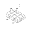
- FIG. 3 is a partial perspective view of the cryopanel 31.
- the cryopanel 31 is composed of a disk made of a metal material having high thermal conductivity such as copper or aluminum.
- the cryopanel 31 has an upper surface facing the inside of the vacuum chamber 10 as a condensing surface 310 that condenses water vapor to be exhausted.
- the cryopanel 31 is not limited to a disk shape, and may be a rectangular shape.
- the cryopanel 31 is not limited to a flat plate, and may be a curved plate, a cylindrical shape, or the like.
- the condensing surface 310 has a plurality of independent dividing surfaces 310a.
- Each dividing surface 310a is partitioned by a plurality of grooves 310b (boundary portions) formed in a lattice shape on the condensing surface 310. Thereby, each division surface 310a is scattered on the condensation surface 310 as an island isolated from each other.
- FIG. 2 is shown in a simplified manner for easy understanding, and actually, the dividing surface 310a is formed finer than the illustrated example.
- the groove 310b constitutes a boundary between a plurality of adjacent divided surfaces 310a.
- the groove part 310b has a substantially triangular (V-shaped) cross-sectional shape.
- a plurality of groove portions 310b are linearly formed in two axial directions (X-axis direction and Y-axis direction) perpendicular to each other in the plane so that each divided surface 310a is a square.
- the width, depth, and formation interval of the groove portion 310b are not particularly limited, and are appropriately set according to the size (area), interval, and the like of each divided surface 310a.
- the width, depth, and formation interval of the groove 310b can be 1 mm, 0.5 mm, and 5 mm, respectively.
- the cryopanel 31 is cooled to 80K or less by the refrigerator 32. Residual gas (or released gas) in the vacuum chamber 10 is captured by condensing on the condensing surface 310 of the cryopanel 31, whereby the vacuum chamber 10 is exhausted to the second degree of vacuum.
- the cryopump 30 is mainly operated to exhaust the water vapor (H 2 O) in the vacuum chamber 10.
- gases for example, carbon dioxide, chlorine, ammonia
- these gases are also captured by the cryopanel 31 together with the water vapor and mixed with the water vapor. It accumulates on the condensing surface 310 as a condensate.
- the mixed gas condensate may have cracks on the cryopanel 31 because the internal stress is relatively large due to the difference in heat of condensation and the volume expansion coefficient during condensation.
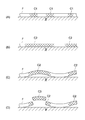
- FIG. 4 is a schematic diagram for explaining the mechanism of separation of the condensate on the condensation surface.
- the crack C1 generated in the condensate (ice film) F on the condensing surface S occurs at an arbitrary position (FIG. 4A), and a relatively large crack C2 is generated through growth and coalescence (FIG. 4 ( B)).
- the crack C2 is peeled off from the condensing surface S (FIG. 4C), and finally a peeling piece C3 is generated (FIG. 4D).
- Separation of the condensate F from the condensing surface S causes a reduction in pump exhaust capacity and raises the pressure in the vacuum chamber by sublimation (revaporization) of the separation piece C3.
- the sublimated gas is recondensed on the condensing surface S, thereby reducing the pressure in the vacuum chamber.
- the cryopanel 31 is partitioned into a plurality of divided surfaces 310a in which the condensing surface 310 is independent by the grooves 310b.
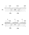
- FIG. 5A shows the condensate F deposited on the condensing surface 310 of the cryopanel 31.
- the condensate F is deposited on the condensing surface 310 in accordance with the surface shapes of the dividing surface 310a and the groove portion 310b.
- FIG. 5B is a schematic diagram showing a state when a crack occurs in the condensate F.
- the individual divided surfaces 310a are scattered on the condensation surface 310 as isolated islands. Therefore, the crack C generated on a certain divided surface 310a is subjected to a large propagation resistance by the groove portion 310b, so that the propagation to another adjacent divided surface and the coalescence of the crack C between the divided surfaces 310a are suppressed. That is, it is possible to control the mode of propagation of the crack C by forming a boundary portion that imparts shape anisotropy to the condensation surface. Therefore, by setting the size of each divided surface 310a to a size that does not cause separation from the divided surface by the crack C, the crack generation region can be kept within the divided surface.
- the internal stress of the condensate F on the condensing surface 310 is alleviated by being distributed to each of the dividing surfaces 310a, and the separation of the condensate F on the dividing surfaces 310a is effectively prevented. Is possible. Thereby, pressure fluctuations in the vacuum chamber caused by separation of the condensate F from the condensing surface 310 and subsequent recondensation can be prevented, and a stable exhaust pressure can be maintained.
- the crack C of the condensate F can also generate
- the shape isotropy is lost between the groove 310b and the dividing surface 310a, the propagation and coalescence of cracks between the groove 310b and the dividing surface 310a are effectively prevented.
- FIG. 6 (A) and 6 (B) show the time change of the exhaust pressure
- FIG. 6 (A) shows an experiment when using the cryopanel according to the comparative example (FIG. 4) in which the condensing surface is formed as a continuous plane.
- FIG. 6 (B) is an experimental result when using the cryopanel 31 according to the present embodiment in which the condensing surface is formed by a plurality of divided surfaces partitioned by the boundary portion.
- the pressure was measured while continuously introducing 130 sccm of water vapor (H 2 O) and 100 sccm of carbon dioxide (CO 2 ) into the vacuum chamber.
- the cooling temperature of the cryopanel was 70K.
- the condensing surface 310 of the cryopanel 31 is formed of the plurality of dividing surfaces 310a by the groove portion 310b, and therefore, the separation of the condensate on the condensing surface 310 can be prevented. .
- the stable exhaust operation by the cryopump 30 can be realized, and the pressure fluctuation in the vacuum chamber can be prevented.
- a vacuum process such as film formation in the vacuum chamber can be stably performed for a long time.
- the plurality of dividing surfaces 310a constituting the condensing surface 310 of the cryopanel 31 have a planar shape, and the cross-sectional shape of the groove 310b that partitions each dividing surface 310a is triangular (V-shaped).
- V-shaped triangular
- the width of the groove 310b is made smaller than that of the dividing surface 310a, the width of the groove 310b may be equal to or larger than the width of the dividing surface 310a.
- 7A to 7C are schematic cross-sectional views of a cryopanel showing a modified example of the condensing surface configuration.
- 7A shows an example in which the dividing surface 410a is formed by a groove 410b having a rectangular cross-sectional shape.
- the groove 410b has a width equal to or greater than that of the dividing surface 410a.
- B shows a configuration example in which a groove 510b having a triangular cross-section is continuously formed so that the slope of the groove 510b is a dividing surface 510a.
- C shows an example in which the width of the groove 610b is equal to or greater than the width of the dividing surface 610a.
- the boundary part that partitions the condensation surface of the cryopanel into a plurality of divided surfaces is configured by the groove part, but the boundary part may be configured by a wall part. Also in this case, the individual divided surfaces can be scattered on the condensation surface as isolated islands.
- An example of this configuration corresponds to, for example, the configuration example of FIG. 7A.
- the groove 410b corresponds to a dividing surface
- the dividing surface 410a corresponds to a wall.
- FIG. 8A shows a cryopanel 71 in which a dividing surface 710a is partitioned by a wall portion 710b having a semicircular cross section.
- FIG. 8B shows a cryopanel 81 in which a dividing surface 810a is partitioned by a wall portion 810b having a triangular cross section.
- cryopanel 91 which divided the division surface 910a with the groove part 910b whose cross-sectional shape is a rectangular shape.
- These cryopanels 71, 81, 91 can be formed by, for example, pressing a metal plate.
- the wall portions 710b and 810b may be divided surfaces, and the divided surfaces 710a and 810a may be groove portions.
- the groove 910b may be a dividing surface, and the dividing surface 910a may be a wall.
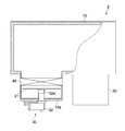
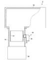
- the vacuum processing apparatus provided with the cryopump 30 is not limited to the above-described configuration example, and may be configured as shown in FIG. 9, for example.
- the vacuum processing apparatus 2 shown in FIG. 9 has a vacuum chamber 10, a main pump 20, a cryopump 30, and a gate valve 40 that partitions the inside of the vacuum chamber 10 and a pump chamber in which the cryopump 30 is installed.
- FIG. 9 the same components as those in FIG. 1 are denoted by the same reference numerals, and detailed description thereof is omitted.
- the gate valve 40 is constituted by an opening / closing valve such as a door valve, and is fully opened when the vacuum chamber 10 is evacuated. Further, when the inside of the vacuum chamber 10 is opened to the atmosphere, it is fully closed, and the pump chamber can be maintained in a vacuum state. Also in the vacuum processing apparatus 2 having such a configuration, it is possible to obtain the same effects as those of the above-described embodiment.
- the vacuum processing apparatus including the cryopump 30 is not limited to the above-described configuration example, and may be configured as shown in FIG.
- the vacuum processing apparatus 3 illustrated in FIG. 10 includes a vacuum chamber 10, a main pump 20, a cryopump 30, and an exhaust passage 15 that connects the vacuum chamber 10 and the main pump 20. 10 that are the same as those in FIG. 1 are given the same reference numerals, and detailed descriptions thereof are omitted.
- the cryopump 30 is attached to the exhaust passage 15 and exhausts gas (for example, water vapor) from the vacuum chamber 10 toward the main pump 20 inside the exhaust passage 15.
- the cryopump 30 includes a cylindrical cryopanel 131 and is disposed inside the exhaust passage 15 concentrically with the exhaust passage 15, for example.
- the same condensation surfaces as described above having a plurality of mutually independent divided surfaces are formed.
- the said condensation surface should just be formed in at least one of the internal peripheral surface of the cryopanel 131, and an outer peripheral surface. Also in the vacuum processing apparatus 3 having such a configuration, it is possible to obtain the same effects as those of the above-described embodiment.
- the number of cryopanels 131 installed in the exhaust passage 15 is not limited to a single one, and may be plural. In this case, a plurality of cylindrical cryopanels having different diameters may be arranged concentrically with each other, or a plurality of cylindrical cryopanels having the same diameter may be arranged in series along the exhaust passage.
- water vapor is exemplified as the gas to be exhausted by the cryopump 30.
- the present invention is not limited to this, and the present invention is also applicable to exhaust of various process gases (for example, nitrogen and argon) used for vacuum processing.
- the invention is applicable.
- nitrogen and argon in the vacuum chamber can be condensed and exhausted.
- the condensate on the cryopanel may crack due to internal stress, but by using the cryopanel according to the present invention, the condensate is prevented from peeling and the fluctuation of exhaust pressure is prevented. It becomes possible to do.
Landscapes
- Engineering & Computer Science (AREA)
- Mechanical Engineering (AREA)
- General Engineering & Computer Science (AREA)
- Compressors, Vaccum Pumps And Other Relevant Systems (AREA)
Abstract
Description
上記パネルは、上記真空チャンバ内の排気すべきガスを凝縮させる凝縮面と、上記凝縮面に形成され上記凝縮面を独立した複数の分割面に区画する境界部とを有する。
上記冷凍機は、上記パネルを上記目標圧力下での上記ガスの露点以下に冷却することが可能である。
上記パネルは、上記真空チャンバ内の排気すべきガスを凝縮させる凝縮面と、上記凝縮面に形成され上記凝縮面を独立した複数の分割面に区画する境界部とを有する。
上記冷凍機は、上記パネルを上記目標圧力下での上記ガスの露点以下に冷却することが可能である。
10…真空チャンバ
15…排気通路
20…主ポンプ
30…クライオポンプ
31、61、71、81、91、131…クライオパネル
32…冷凍機
40…仕切弁
310…凝縮面
310a、410a、510a、610a、710a、810a、910a…分割面
310b、410b、510b、810b、910b…溝部
610b、710b…壁部
Claims (4)
- 真空チャンバを目標圧力に排気するためのクライオポンプであって、
前記真空チャンバ内の排気すべきガスを凝縮させる凝縮面と、前記凝縮面に形成され前記凝縮面を独立した複数の分割面に区画する境界部とを有するパネルと、
前記パネルを前記目標圧力下での前記ガスの露点以下に冷却することが可能な冷凍機と
を具備するクライオポンプ。 - 請求項1に記載のクライオポンプであって、
前記境界部は、前記凝縮面に凹設された溝部であるクライオポンプ。 - 請求項2に記載のクライオポンプであって、
前記溝部は、前記凝縮面に格子状に形成されているクライオポンプ。 - 請求項1に記載のクライオポンプであって、
前記境界部は、前記凝縮面に突設された壁部であるクライオポンプ。
Priority Applications (2)
| Application Number | Priority Date | Filing Date | Title |
|---|---|---|---|
| JP2011534068A JP5433702B2 (ja) | 2009-09-29 | 2010-09-28 | 真空処理装置 |
| CN2010800433845A CN102667156A (zh) | 2009-09-29 | 2010-09-28 | 低温泵 |
Applications Claiming Priority (2)
| Application Number | Priority Date | Filing Date | Title |
|---|---|---|---|
| JP2009-225160 | 2009-09-29 | ||
| JP2009225160 | 2009-09-29 |
Publications (1)
| Publication Number | Publication Date |
|---|---|
| WO2011040002A1 true WO2011040002A1 (ja) | 2011-04-07 |
Family
ID=43825848
Family Applications (1)
| Application Number | Title | Priority Date | Filing Date |
|---|---|---|---|
| PCT/JP2010/005838 Ceased WO2011040002A1 (ja) | 2009-09-29 | 2010-09-28 | クライオポンプ |
Country Status (5)
| Country | Link |
|---|---|
| JP (1) | JP5433702B2 (ja) |
| KR (1) | KR20120048689A (ja) |
| CN (1) | CN102667156A (ja) |
| TW (1) | TW201118250A (ja) |
| WO (1) | WO2011040002A1 (ja) |
Citations (4)
| Publication number | Priority date | Publication date | Assignee | Title |
|---|---|---|---|---|
| JPS59229071A (ja) * | 1983-06-10 | 1984-12-22 | Mitsubishi Heavy Ind Ltd | 極低温液体で吸着板を冷却する吸着ポンプ |
| JPS60249678A (ja) * | 1984-05-25 | 1985-12-10 | Toshiba Corp | クライオポンプ |
| JPS63243470A (ja) * | 1987-03-30 | 1988-10-11 | Toshiba Corp | 真空排気装置 |
| WO2008088794A2 (en) * | 2007-01-17 | 2008-07-24 | Brooks Automation, Inc. | Pressure burst free high capacity cryopump |
Family Cites Families (5)
| Publication number | Priority date | Publication date | Assignee | Title |
|---|---|---|---|---|
| KR20010006278A (ko) * | 1997-04-18 | 2001-01-26 | 사이스 푸어 가스 인코포레이티드 | 인시튜 게터펌프시스템 및 방법 |
| US5974809A (en) * | 1998-01-21 | 1999-11-02 | Helix Technology Corporation | Cryopump with an exhaust filter |
| JP4547076B2 (ja) * | 2000-08-31 | 2010-09-22 | アルバック・クライオ株式会社 | クライオトラップ |
| WO2005050018A1 (ja) * | 2003-11-20 | 2005-06-02 | Sumitomo Heavy Industries, Ltd. | クライオポンプ |
| JP2007154785A (ja) * | 2005-12-06 | 2007-06-21 | Fuji Electric Holdings Co Ltd | コールドトラップおよび真空排気装置 |
-
2010
- 2010-09-28 KR KR1020127007282A patent/KR20120048689A/ko not_active Ceased
- 2010-09-28 JP JP2011534068A patent/JP5433702B2/ja active Active
- 2010-09-28 CN CN2010800433845A patent/CN102667156A/zh active Pending
- 2010-09-28 WO PCT/JP2010/005838 patent/WO2011040002A1/ja not_active Ceased
- 2010-09-29 TW TW099133144A patent/TW201118250A/zh unknown
Patent Citations (4)
| Publication number | Priority date | Publication date | Assignee | Title |
|---|---|---|---|---|
| JPS59229071A (ja) * | 1983-06-10 | 1984-12-22 | Mitsubishi Heavy Ind Ltd | 極低温液体で吸着板を冷却する吸着ポンプ |
| JPS60249678A (ja) * | 1984-05-25 | 1985-12-10 | Toshiba Corp | クライオポンプ |
| JPS63243470A (ja) * | 1987-03-30 | 1988-10-11 | Toshiba Corp | 真空排気装置 |
| WO2008088794A2 (en) * | 2007-01-17 | 2008-07-24 | Brooks Automation, Inc. | Pressure burst free high capacity cryopump |
Also Published As
| Publication number | Publication date |
|---|---|
| JP5433702B2 (ja) | 2014-03-05 |
| JPWO2011040002A1 (ja) | 2013-02-21 |
| KR20120048689A (ko) | 2012-05-15 |
| CN102667156A (zh) | 2012-09-12 |
| TW201118250A (en) | 2011-06-01 |
Similar Documents
| Publication | Publication Date | Title |
|---|---|---|
| JP5553638B2 (ja) | コールドトラップ、及び真空排気装置 | |
| JPS5825873B2 (ja) | 低温ポンプによる排気方法及びその装置 | |
| JP2010014066A (ja) | クライオポンプ | |
| JP5679218B2 (ja) | クライオポンプ、クライオポンプの製造方法、及び真空排気方法 | |
| US7997089B2 (en) | Method and apparatus for regeneration water | |
| JP5433702B2 (ja) | 真空処理装置 | |
| CN101294284A (zh) | 一种耐冲蚀抗疲劳等离子表面复合强化方法 | |
| CN105179199A (zh) | 一种低温泵 | |
| JP2007327396A (ja) | クライオポンプおよび半導体製造装置 | |
| US20250067257A1 (en) | Method for vacuum-exhausting by means of cryopump | |
| US8658004B2 (en) | Vapor-barrier vacuum isolation system | |
| CN102743894A (zh) | 冷阱及真空排气装置 | |
| Perekrestov et al. | Selective processes that proceed during formation of aluminum layers near the phase equilibrium in a plasma-condensate system | |
| Strzyzewski et al. | Behaviour of gas conditions during vacuum arc discharges used for deposition of thin films | |
| TWI845097B (zh) | 低溫泵 | |
| JP2002070738A (ja) | クライオトラップ | |
| US20250188916A1 (en) | Cryopump | |
| JP4980181B2 (ja) | クライオパネル | |
| JP2011137423A (ja) | クライオポンプ、基板処理装置、電子デバイスの製造方法 | |
| CN205154538U (zh) | 一种加速抽取真空气体的低温泵 | |
| KR100235686B1 (ko) | 진공배기장치 | |
| Shen | Ultrahigh vacuum systems using low temperature pumps | |
| Lee et al. | Study on the measurement of activation temperature of Non-Evaporable Getter | |
| Hablanian | Vapor Jet Pumps (Diffusion Pumps) | |
| CN106637102A (zh) | 一种金属薄膜的制作工艺 |
Legal Events
| Date | Code | Title | Description |
|---|---|---|---|
| WWE | Wipo information: entry into national phase |
Ref document number: 201080043384.5 Country of ref document: CN |
|
| 121 | Ep: the epo has been informed by wipo that ep was designated in this application |
Ref document number: 10820124 Country of ref document: EP Kind code of ref document: A1 |
|
| ENP | Entry into the national phase |
Ref document number: 20127007282 Country of ref document: KR Kind code of ref document: A |
|
| NENP | Non-entry into the national phase |
Ref country code: DE |
|
| WWE | Wipo information: entry into national phase |
Ref document number: 2011534068 Country of ref document: JP |
|
| 122 | Ep: pct application non-entry in european phase |
Ref document number: 10820124 Country of ref document: EP Kind code of ref document: A1 |