WO2011039961A1 - High-frequency heating device and high-frequency heating method - Google Patents

High-frequency heating device and high-frequency heating method Download PDF

Info

Publication number
WO2011039961A1
WO2011039961A1 PCT/JP2010/005631 JP2010005631W WO2011039961A1 WO 2011039961 A1 WO2011039961 A1 WO 2011039961A1 JP 2010005631 W JP2010005631 W JP 2010005631W WO 2011039961 A1 WO2011039961 A1 WO 2011039961A1
Authority
WO
WIPO (PCT)
Prior art keywords
frequency power
frequency
unit
phase
power
Prior art date
Application number
PCT/JP2010/005631
Other languages
French (fr)
Japanese (ja)
Inventor
岡島 利幸
Original Assignee
パナソニック株式会社
Priority date (The priority date is an assumption and is not a legal conclusion. Google has not performed a legal analysis and makes no representation as to the accuracy of the date listed.)
Filing date
Publication date
Application filed by パナソニック株式会社 filed Critical パナソニック株式会社
Priority to EP10820087.4A priority Critical patent/EP2485565A4/en
Priority to CN2010800300646A priority patent/CN102474924B/en
Priority to JP2011534054A priority patent/JP4995350B2/en
Priority to US13/382,222 priority patent/US8796593B2/en
Publication of WO2011039961A1 publication Critical patent/WO2011039961A1/en

Links

Images

Classifications

    • HELECTRICITY
    • H05ELECTRIC TECHNIQUES NOT OTHERWISE PROVIDED FOR
    • H05BELECTRIC HEATING; ELECTRIC LIGHT SOURCES NOT OTHERWISE PROVIDED FOR; CIRCUIT ARRANGEMENTS FOR ELECTRIC LIGHT SOURCES, IN GENERAL
    • H05B6/00Heating by electric, magnetic or electromagnetic fields
    • H05B6/64Heating using microwaves
    • H05B6/66Circuits
    • H05B6/68Circuits for monitoring or control
    • H05B6/686Circuits comprising a signal generator and power amplifier, e.g. using solid state oscillators
    • HELECTRICITY
    • H05ELECTRIC TECHNIQUES NOT OTHERWISE PROVIDED FOR
    • H05BELECTRIC HEATING; ELECTRIC LIGHT SOURCES NOT OTHERWISE PROVIDED FOR; CIRCUIT ARRANGEMENTS FOR ELECTRIC LIGHT SOURCES, IN GENERAL
    • H05B6/00Heating by electric, magnetic or electromagnetic fields
    • H05B6/64Heating using microwaves
    • H05B6/70Feed lines
    • H05B6/705Feed lines using microwave tuning
    • HELECTRICITY
    • H05ELECTRIC TECHNIQUES NOT OTHERWISE PROVIDED FOR
    • H05BELECTRIC HEATING; ELECTRIC LIGHT SOURCES NOT OTHERWISE PROVIDED FOR; CIRCUIT ARRANGEMENTS FOR ELECTRIC LIGHT SOURCES, IN GENERAL
    • H05B2206/00Aspects relating to heating by electric, magnetic, or electromagnetic fields covered by group H05B6/00
    • H05B2206/04Heating using microwaves
    • H05B2206/044Microwave heating devices provided with two or more magnetrons or microwave sources of other kind
    • YGENERAL TAGGING OF NEW TECHNOLOGICAL DEVELOPMENTS; GENERAL TAGGING OF CROSS-SECTIONAL TECHNOLOGIES SPANNING OVER SEVERAL SECTIONS OF THE IPC; TECHNICAL SUBJECTS COVERED BY FORMER USPC CROSS-REFERENCE ART COLLECTIONS [XRACs] AND DIGESTS
    • Y02TECHNOLOGIES OR APPLICATIONS FOR MITIGATION OR ADAPTATION AGAINST CLIMATE CHANGE
    • Y02BCLIMATE CHANGE MITIGATION TECHNOLOGIES RELATED TO BUILDINGS, e.g. HOUSING, HOUSE APPLIANCES OR RELATED END-USER APPLICATIONS
    • Y02B40/00Technologies aiming at improving the efficiency of home appliances, e.g. induction cooking or efficient technologies for refrigerators, freezers or dish washers

Definitions

  • the present invention relates to a high-frequency heating device and a high-frequency heating method for heating an object to be heated housed in a heating chamber.
  • Conventional high-frequency heating devices generally have a high-frequency power generation unit composed of a vacuum tube called a magnetron.
  • Patent Document 1 discloses a technique for heating the object to be heated in a preferable state by controlling the frequency and phase difference of high-frequency power radiated from a plurality of radiating portions so that the reflected power is minimized.
  • the frequency and phase conditions of the high-frequency power to be optimized must be individually changed within a set range, and the reflected power must be detected in all combinations of conditions. Therefore, there is a problem that it takes time until the optimum heating condition is determined after the user places the object to be heated in the heating chamber and presses the use start button.
  • This invention solves the said conventional subject, and aims at providing the high frequency heating apparatus which determines optimal heating conditions in a short time.
  • a high-frequency heating device is a high-frequency heating device that heats an object to be heated stored in a heating chamber, and generates at least one high-frequency power having a set frequency.
  • a high-frequency power generation unit, a variable phase shift unit that changes the phase of the high-frequency power generated by the high-frequency power generation unit, and a radiation unit that radiates high-frequency power whose phase has been changed by the variable phase shift unit to the heating chamber A plurality of high-frequency power units each including a back-flow power detection unit that detects a back-flow power that is part of the high-frequency power radiated from the radiating unit and is incident on the radiating unit from the heating chamber;
  • a control unit that sets a frequency in the high frequency power generation unit and sets a phase shift amount in the variable phase shift unit, and the backflow power detection unit is set in the high frequency power generation unit by the control unit.
  • a part of the high-frequency power radiated from the radiating part of the one high-frequency power unit is reflected, and the reflected wave that is the backflow power by the reflection input to the radiating part of the one high-frequency power unit Amplitude and phase, and amplitude and phase of a through wave in which a part of the high-frequency power radiated from the radiating part of the other high-frequency power unit is the backflow power input to the radiating part of the one high-frequency power unit.
  • the control unit sequentially sets a plurality of frequencies in the high-frequency power generation unit, and sets the amplitude and phase of the reflected wave and the through wave in the backflow power detection unit of each high-frequency power unit for each set frequency.
  • the amplitude and phase of the wave are detected, and the object to be heated is heated based on the detected amplitude and phase of the plurality of reflected waves and the amplitude and phase of the through wave Determining the frequency of the high-frequency power generated in the high-frequency power generation unit and the phase shift amount in the variable phase shift unit, and setting the determined frequency and phase shift amount in the high-frequency power generation unit and the variable phase shift unit.
  • the irradiation efficiency can be obtained without actually measuring all the combinations of the frequency of each high-frequency power generation unit and the amount of phase shift of each variable phase shift unit.
  • the setting frequency of each high frequency electric power generation part and the setting phase shift amount of each variable phase shift part for maximizing irradiation efficiency can be determined in a very short time.
  • control unit uses the detected amplitude and phase of the reflected wave, and the amplitude and phase of the through wave, for each frequency that can be set in the high-frequency power generation unit, in the variable phase shift unit.
  • the amplitude and phase of the reflected wave and the amplitude and phase of the through wave in an arbitrary combination of phase shift amounts are estimated by calculation, and the amplitude and phase of the reflected wave detected for each frequency and the amplitude of the through wave and
  • a combination of the frequency of the high frequency power generated by the high frequency power generation unit and the amount of phase shift in the variable phase shift unit may be determined.
  • control unit determines the combination that minimizes the sum of the reflected wave and the through wave detected by the backflow power detection unit of each high-frequency power unit from the arbitrary combinations. Also good.
  • the backflow power detection unit includes a quadrature detection unit, and the quadrature detection unit performs quadrature detection of the backflow power using the high frequency power generated by the high frequency power generation unit.
  • An in-phase detection signal and a quadrature detection signal for calculating the amplitude and phase and the amplitude and phase of the through wave may be detected.
  • each high-frequency power unit to radiate high-frequency power to the heating chamber independently of each other, so that reflected waves and through waves can be easily detected.
  • Each of the plurality of high-frequency power units further includes a high-frequency power amplification unit that amplifies the high-frequency power generated by the high-frequency power generation unit and the gain of the amplification is variable, and the control unit further includes: The amplification gain in the high frequency power amplification unit may be set.
  • This configuration can simplify the control in the control unit.
  • the high-frequency heating device includes one high-frequency power generation unit and a plurality of the high-frequency power units, and further distributes high-frequency power generated by the single high-frequency power generation unit and distributes the high-frequency power. You may provide the distribution part which supplies electric power to the said several high frequency electric power unit.
  • control unit sets the frequency of the high-frequency power generation unit to the frequency for through-wave measurement when the backflow power detection unit in one high-frequency power unit detects the amplitude and phase of the through-wave.
  • amplification gain in the high-frequency power amplification unit may be set so that the amplitude of the reflected wave in the one high-frequency power unit is smaller than the amplitude of the through wave.
  • control unit is configured such that when the backflow power detection unit in one high-frequency power unit detects the amplitude and phase of the reflected wave, the control unit compares the amplitude of the reflected wave with the one high-frequency power unit.
  • An amplification gain in the high-frequency power amplifier may be set so that the amplitude of the through wave becomes small.
  • the high-frequency heating device may include a plurality of the high-frequency power generation units, and the plurality of high-frequency power generation units may supply the generated plurality of high-frequency powers to the plurality of high-frequency power units.
  • This configuration can further reduce the time required to detect the reflected wave. Moreover, since each of the frequency of the high frequency electric power generated in the some high frequency electric power generation part can be set independently, irradiation efficiency can be improved.
  • one of the plurality of high-frequency power generation units and the plurality of high-frequency power units may be provided in a one-to-one correspondence.
  • This configuration can further reduce the time required to detect the reflected wave. Moreover, the irradiation efficiency can be further increased.
  • the plurality of high-frequency power units are provided corresponding to the plurality of high-frequency power generation units, and the control unit is configured so that the backflow power detection unit in one of the high-frequency power units has an amplitude and a phase of the through wave.
  • the same frequency is set in the high-frequency power generation unit corresponding to the one high-frequency power unit and the high-frequency power generation unit corresponding to the other high-frequency power unit, and the through
  • the amplification gain in the high-frequency power amplifier may be set so that the amplitude of the reflected wave in the one high-frequency power unit is smaller than the amplitude of the wave.
  • the plurality of high-frequency power units are provided corresponding to the plurality of high-frequency power generation units, and the control unit is configured with a frequency set in the high-frequency power generation unit corresponding to one of the high-frequency power units,
  • the frequency set in the high-frequency power generation unit corresponding to the one high-frequency power unit is equal and the backflow power detection unit in the one high-frequency power unit detects the amplitude and phase of the reflected wave
  • the amplification gain in the high frequency power amplifier may be set so that the amplitude of the through wave in the one high frequency power unit is smaller than the amplitude of the reflected wave in the one high frequency power unit. Good.
  • control unit executes determination of a frequency of the high-frequency power generation unit and a phase shift amount of the variable phase shift unit as a pre-search process before a heating process for the object to be heated, and the high-frequency Re-determination of the frequency of the power generation unit and the phase shift amount of the variable phase shift unit is performed as a re-search process during the heating process for the object to be heated, and when the pre-search process or the re-search process is performed
  • the high-frequency power radiated from the radiating unit of the plurality of high-frequency power units has a value smaller than the high-frequency power radiated from the radiating unit during the heat treatment.
  • the amplification gain of the high frequency power amplification unit may be set.
  • This configuration can prevent the high-frequency heating device, particularly the high-frequency power amplification unit including the semiconductor element from being destroyed.
  • control unit may execute the determination of the frequency of the high-frequency power generation unit and the phase shift amount of the variable phase shift unit as a pre-search process before the heating process for the object to be heated.
  • This configuration enables the high-frequency heating device to heat the object to be heated under the optimum heating conditions determined before heating.
  • control unit further executes redetermination of the frequency of the high-frequency power generation unit and the phase shift amount of the variable phase shift unit as a re-search process during the heating process for the object to be heated.
  • a new frequency determined by the search process may be set in the high-frequency power generation unit, and a new phase shift amount may be set in the variable phase shift unit.
  • control unit causes each of the plurality of high-frequency power units to detect the backflow power during the heating process on the object to be heated, and when at least one of the detected plurality of backflow power exceeds a threshold value.
  • the re-search process may be executed.
  • variable phase shifter may be a phase shifter provided corresponding to each of the plurality of high frequency power units.
  • variable phase shift unit is provided corresponding to each of the at least one high frequency power generation unit, and the high frequency power generated from the corresponding high frequency power generation unit according to the phase shift amount set by the control unit. It may be a PLL (Phase Locked Loop) circuit that changes the phase.
  • PLL Phase Locked Loop
  • the high-frequency heating method according to the present invention is a high-frequency heating method in which an object to be heated housed in a heating chamber is heated by high-frequency power radiated from a plurality of high-frequency power units, and is radiated from the plurality of high-frequency power units.
  • a setting step for setting the frequency of the high frequency power to be generated, and a part of the high frequency power radiated from the one high frequency power unit is reflected and input to the one high frequency power unit based on the set frequency.
  • the determining step radiates from the plurality of high frequency power units using the amplitude and phase of the reflected wave detected in the first detecting step and the second detecting step and the amplitude and phase of the through wave.
  • the amplitude and phase of the reflected wave in any combination of the phases of the high-frequency power radiated from the plurality of high-frequency power units, and the amplitude and phase of the through wave for each settable frequency of the high-frequency power to be
  • An estimation step of estimating by calculating using the amplitude and phase of the reflected wave and the amplitude and phase of the through wave; and the amplitude of the reflected wave detected in the first detection step and the second detection step; Phase, amplitude and phase of the through wave, amplitude and phase of the reflected wave estimated in the estimation step, and reflection And a amplitude and phase, wherein the time of heating an object may include a combination determining a combination of the high-frequency power having a frequency and phase that are emitted from the plurality of high-
  • the high-frequency heating apparatus and high-frequency heating method of the present invention can determine the optimum heating conditions in a short time.
  • FIG. 1 is a block diagram illustrating a basic configuration of the high-frequency heating device according to the first embodiment.
  • FIG. 2 is a block diagram showing a specific configuration of the high-frequency power generation unit.
  • FIG. 3 is a block diagram showing a specific configuration of the first high-frequency power unit.
  • FIG. 4 is a flowchart showing a basic control procedure of the high-frequency heating device.
  • FIG. 5 is a flowchart showing a control procedure for detecting the reflected power.
  • FIG. 6 is a flowchart showing a control procedure for detecting the through power.
  • FIG. 7 is a flowchart showing the control procedure of the pre-search process.
  • FIG. 1 is a block diagram illustrating a basic configuration of the high-frequency heating device according to the first embodiment.
  • FIG. 2 is a block diagram showing a specific configuration of the high-frequency power generation unit.
  • FIG. 3 is a block diagram showing a specific configuration of the first high-frequency power unit.
  • FIG. 4 is a
  • FIG. 8 is an example of a matrix showing the reflected power of each high-frequency power unit at each frequency and the amplitude and phase of through power between each high-frequency power unit.
  • FIG. 9 is a table showing the irradiation loss of each high-frequency power unit calculated corresponding to the combination of frequency and phase shift amount.
  • FIG. 10 is a table showing the irradiation loss of the entire high-frequency heating apparatus calculated corresponding to the combination of the frequency and the amount of phase shift.
  • FIG. 11 is a diagram illustrating combinations of phase shift amounts using vector synthesis.
  • FIG. 12 is a flowchart showing the control procedure of the re-search process.
  • FIG. 13 is a block diagram illustrating a basic configuration of the high-frequency heating device according to the second embodiment.
  • FIG. 14 is a flowchart showing a control procedure for detecting the reflected power.
  • FIG. 15 is a flowchart illustrating a control procedure for detecting through power.
  • FIG. 16 is a flowchart showing the control procedure of the pre-search process.
  • FIG. 17 is a flowchart showing the control procedure of the re-search process.
  • FIG. 18 is a block diagram illustrating a basic configuration of the high-frequency heating device according to the third embodiment.
  • FIG. 19 is a flowchart showing a control procedure for detecting the reflected power.
  • FIG. 20 is a flowchart illustrating an example of a control procedure for detecting through power.
  • FIG. 21 is a flowchart illustrating another example of the control procedure for detecting the through power.
  • FIG. 22 is an external view of the high-frequency heating device.
  • a high-frequency heating device is a high-frequency heating device that heats an object to be heated housed in a heating chamber, and includes at least one high-frequency power generation unit that generates high-frequency power of a set frequency, and the high-frequency power A variable phase shift unit that changes the phase of the high-frequency power generated in the generation unit, a radiation unit that radiates high-frequency power whose phase is changed in the variable phase shift unit to the heating chamber, and a radiation unit that is radiated from the radiation unit.
  • a plurality of high-frequency power units each including a back-flow power detection unit that detects a back-flow power that is part of the high-frequency power and is incident on the radiation unit from the heating chamber, and sets a frequency in the high-frequency power generation unit.
  • a control unit that sets a phase shift amount in the variable phase shift unit, wherein the backflow power detection unit is configured to detect the high frequency based on the frequency set in the high frequency power generation unit by the control unit.
  • a part of the high-frequency power radiated from the radiating part of the power unit is reflected and the amplitude and phase of the reflected wave, which is the backflow power due to the reflection input to the radiating part of the one high-frequency power unit, and the other high-frequency wave
  • a part of the high-frequency power radiated from the radiating unit of the power unit detects the amplitude and phase of a through wave that is a reverse power input to the radiating unit of the one high-frequency power unit, and the control unit
  • a plurality of frequencies are sequentially set in the high frequency power generation unit, and the backflow power detection unit of each high frequency power unit detects the amplitude and phase of the reflected wave and the amplitude and phase of the through wave for each set frequency.
  • FIG. 1 is a block diagram showing a configuration of a high-frequency heating device according to Embodiment 1 of the present invention.
  • a high-frequency heating apparatus 100 shown in the figure is a high-frequency heating apparatus that heats an object to be heated housed in a heating chamber, and includes a control unit 110, a high-frequency power generation unit 120, a distribution unit 130, and a first high-frequency heating device.
  • a power unit 140a, a second high-frequency power unit 140b, a third high-frequency power unit 140c, a fourth high-frequency power unit 140d, and radiation parts 150a to 150d are provided.
  • the high-frequency power units the first high-frequency power unit 140a, the second high-frequency power unit 140b, the third high-frequency power unit 140c, and the fourth high-frequency power unit 140d
  • the high-frequency power unit 140 It describes.
  • the first high-frequency power unit 140a, the second high-frequency power unit 140b, the third high-frequency power unit 140c, and the fourth high-frequency power unit 140d are respectively a high-frequency power unit 140a, a high-frequency power unit 140b, and a high-frequency power unit 140c. And may be described as a high-frequency power unit 140d.
  • the high-frequency heating apparatus 100 includes four high-frequency power units, but the number of high-frequency power units is not limited to this.
  • the control unit 110 controls the frequency, phase, and output level of a plurality of high-frequency powers radiated from the radiation units 150a to 150d. Specifically, the control unit 110 outputs a frequency control signal Cfreq for instructing the frequency to the high frequency power generation unit 120, and sets the amount of phase shift of the high frequency power generated by the high frequency power unit 140 to each high frequency power unit 140.
  • the instructed phase shift amount control signals Cps1 to Cps4 and amplification gain control signals Camp1 to Camp4 indicating the amplification gain in the high frequency power unit 140 are output. Further, optimum heating conditions are determined from in-phase detection signals I (1) to I (4) and quadrature detection signals Q (1) to Q (4) indicating detection results in each high-frequency power unit 140.
  • the high frequency power generation unit 120 is a frequency variable power generation unit that generates high frequency power having a frequency set by the control unit 110. Specifically, it is, for example, a PLL (Phase Locked Loop) circuit that generates high-frequency power having a frequency corresponding to the frequency control signal Cfreq input from the control unit 110.
  • PLL Phase Locked Loop
  • FIG. 2 is a block diagram showing a specific configuration of the high-frequency power generation unit 120.
  • the high-frequency power generation unit 120 shown in the figure includes an oscillation unit 121, a phase locked loop 122, and an amplification unit 123.
  • the oscillation unit 121 is, for example, a VCO (Voltage Controlled Oscillator) that generates a high-frequency signal having a frequency corresponding to the voltage output from the phase-locked loop 122.
  • VCO Voltage Controlled Oscillator
  • the phase-locked loop 122 adjusts the output voltage so that the frequency of the high-frequency power generated from the oscillation unit 121 and the frequency control signal Cfreq indicating the set frequency input from the control unit 110 are the same frequency.
  • the amplifying unit 123 is, for example, a transistor that amplifies the high frequency power generated by the oscillating unit 121.
  • the high-frequency power generation unit 120 generates high-frequency power having a frequency set by the control unit 110.
  • the amplifying unit 123 is shown as a single power amplifier, but the amplifying unit 123 may be configured with a plurality of power amplifiers in order to obtain a high output and large output power.
  • the amplifying unit 123 including a plurality of power amplifiers may be configured by connecting the plurality of power amplifiers in a multistage series or by connecting them in parallel to synthesize output power.
  • the high frequency power generated by the high frequency power generation unit 120 is divided into four by the distribution unit 130 and input to the high frequency power units 140a to 140d.
  • Each of the high frequency power units 140a to 140d changes the phase of the high frequency power input via the distribution unit 130 by the amount of phase shift set by the control unit 110, and the control unit 110 converts the high frequency power whose phase has been changed by the control unit 110.
  • Amplification is performed with the set amplification gain, and the radiation is radiated to the heating chamber via the corresponding radiation portions 150a to 150d.
  • the high frequency power units 140a to 140d change the phase of the high frequency power according to the phase shift amount control signals Cps1 to Cps4 indicating the phase shift amount input from the control unit 110.
  • the high-frequency power whose phase has been changed is amplified in accordance with the amplification gain control signals Camp1 to Camp4 indicating the amplification gain input from the control unit 110.
  • the high frequency power units 140a to 140d detect the backflow power incident from the heating chamber via the corresponding radiation portions 150a to 150d. Specifically, the in-phase detection signals I (1) to I (4) and the quadrature detection signal Q (1), which are signals for detecting the amplitude and phase of the backflow power input via the radiation units 150a to 150d, are detected. ⁇ Q (4) is output to the control unit 110. The detailed configuration of the high-frequency power units 140a to 140d will be described later.
  • the radiating units 150a to 150d are provided in one-to-one correspondence with the high frequency power units 140a to 140d, respectively, radiate high frequency power generated by the corresponding high frequency power units 140a to 140d into the heating chamber, and enter from the heating chamber.
  • an antenna For example, an antenna.
  • the radiating portions 150a to 150d are drawn separately from the high frequency power units 140a to 140d, but this is only an example, and the high frequency power units 140a to 140d include the radiating portions 150a to 150d. It may be.
  • the first high-frequency power unit 140a includes a distribution unit 141a, a variable phase shift unit 142a, a high-frequency power amplification unit 143a, a directional coupling unit 144a, and a quadrature detection unit 145a.
  • the second high frequency power unit 140b includes a distribution unit 141b, a variable phase shift unit 142b, a high frequency power amplification unit 143b, a directional coupling unit 144b, and a quadrature detection unit 145b.
  • the third high frequency power unit 140c includes a distribution unit 141c, a variable phase shift unit 142c, a high frequency power amplification unit 143c, a directional coupling unit 144c, and a quadrature detection unit 145c.
  • the fourth high-frequency power unit 140d includes a distribution unit 141d, a variable phase shift unit 142d, a high-frequency power amplification unit 143d, a directional coupling unit 144d, and a quadrature detection unit 145d.
  • the high frequency power units 140a to 140d have the same configuration. That is, distribution sections 141a to 141d, variable phase shift sections 142a to 142d, high frequency power amplification sections 143a to 143d, directional coupling sections 144a to 144d, and quadrature detection sections 145a to 145d have the same configuration. . Therefore, only the first high-frequency power unit 140a will be described below, but the first high-frequency power unit 140a is also used for the second high-frequency power unit 140b, the third high-frequency power unit 140c, and the fourth high-frequency power unit 140d. The same processing is performed.
  • the distribution units 141a to 141d, the variable phase shift units 142a to 142d, the high frequency power amplification units 143a to 143d, the directional coupling units 144a to 144d, and the quadrature detection units 145a to 145d are particularly distinguished from each other.
  • a distribution unit 141, a variable phase shift unit 142, a high-frequency power amplification unit 143, a directional coupling unit 144, and a quadrature detection unit 145 may be described as the radiating portion 150 without being particularly distinguished.
  • the in-phase detection signals I (1) to I (4) and the quadrature detection signals Q (1) to Q (4) are respectively referred to as the in-phase detection signal I and the quadrature detection signal Q without making any distinction. There is a case.
  • FIG. 3 is a block diagram showing a specific configuration of the first high-frequency power unit 140a.
  • the same figure also shows the control part 110 and the radiation
  • the first high-frequency power unit 140a includes a distribution unit 141, a variable phase shift unit 142, a high-frequency power amplification unit 143, a directional coupling unit 144, and a quadrature detection unit 145.
  • the distribution unit 141, the variable phase shift unit 142, the high frequency power amplification unit 143, the directional coupling unit 144, and the radiation unit 150a are connected in series in this order.
  • the quadrature detection unit 145 is connected to the distribution unit 141 and the directional coupling unit 144.
  • the directional coupling unit 144 and the quadrature detection unit 145 correspond to a backflow power detection unit of the present invention.
  • the distribution unit 141 distributes the high-frequency power input from the high-frequency power generation unit 120 through the distribution unit 130 into two.
  • any of a resistance distributor, a directional coupler, and a hybrid coupler may be used.
  • the variable phase shift unit 142 changes the phase of the high-frequency power distributed by the distribution unit 141 by the phase shift amount set by the control unit 110. Specifically, the variable phase shifter 142 changes the phase of the input high-frequency signal in accordance with the phase shift amount control signal Cps1 indicating the phase shift amount input from the controller 110.
  • the variable phase shifter 142 for example, a multi-bit step variable phase shifter or a continuous variable phase shifter can be used.
  • a multi-bit step variable phase shifter (for example, a 3-bit step variable phase shifter) is used in digital control, and controls the phase shift amount in several steps in combination with path switching.
  • the phase shift amount is determined based on a phase shift amount control signal Cps1, which is a control signal indicating the phase shift amount input from the outside.
  • the continuously variable phase shifter is used for analog voltage control, and is known as a loaded line type phase shifter using a transmission line and a hybrid coupled type phase shifter using a 90 ° hybrid coupler, for example.
  • a phase shift amount control signal Cps1 which is a control signal indicating the phase shift amount input from the outside.
  • the high frequency power amplification unit 143 amplifies the high frequency power signal whose phase is changed by the variable phase shift unit 142 with an amplification gain corresponding to the amplification gain control signal Camp1 input from the control unit 110.
  • the high frequency power amplifying unit 143 includes a variable attenuator 151 and a high frequency power amplifier 152, and an amplification gain control signal Camp 1 is input from the control unit 110 to the variable attenuator 151.
  • the high-frequency power amplifier 152 is illustrated as being composed of one power amplifier. However, in order to obtain a high output and a large output power, the high-frequency power amplifier 152 is composed of a plurality of power amplifiers. It may be. In this case, the high-frequency power amplifier 152 including a plurality of power amplifiers may be configured by connecting the plurality of power amplifiers in a multistage series, or by connecting them in parallel to synthesize output power.
  • the variable attenuator 151 attenuates the high frequency power whose phase has been changed by the variable phase shifter 142 by an attenuation amount corresponding to the amplified gain control signal Camp1 input from the controller 110.
  • the configuration of the variable attenuator 151 is well known. For example, a multi-bit step variable attenuator or a continuous variable attenuator can be used.
  • Multi-bit step variable attenuators are used in digital control, and control the attenuation in several steps step by step by switching FET switches ON / OFF and path switching. To do.
  • the attenuation amount is determined based on a control signal indicating the attenuation amount input from the outside.
  • the continuously variable attenuator is used for analog voltage control.
  • a continuously variable attenuator using a PIN junction diode is known.
  • the reverse bias voltage of the PIN junction diode By changing the reverse bias voltage of the PIN junction diode, the high-frequency resistance value between the two poles is changed to continuously change the attenuation.
  • the attenuation amount is determined based on a control signal indicating the attenuation amount input from the outside.
  • the high frequency power amplifier 152 is, for example, a transistor that amplifies the high frequency signal attenuated by the variable attenuator 151 with a predetermined amplification factor.
  • the high-frequency power amplifier 143 attenuates the high-frequency power input according to the attenuation set by the amplification gain control signal Camp1, and amplifies the attenuated high-frequency power with a predetermined amplification factor. That is, the amplifier has a variable amplification gain for amplifying an input high-frequency signal with an amplification gain corresponding to the attenuation set by the amplification gain control signal Camp1.
  • variable gain amplifier may be used instead of the variable attenuator 151.
  • the amplification gain is determined based on a control signal indicating the amplification gain input from the outside.
  • the directional coupling unit 144 demultiplexes a part of the reverse power, which is the power flowing back from the radiating unit 150 a to the high frequency power amplifier 143, and inputs the demultiplexed power to the quadrature detector 145.
  • the high frequency power amplified by the high frequency power amplifier 143 is output to the radiation unit 150a, and the high frequency power amplified by the high frequency power amplifier 143 is prevented from wrapping around the quadrature detector 145 which is a circuit on the reception side. . That is, the high frequency power amplified by the high frequency power amplification unit 143 is radiated from the radiation unit 150a to the heating chamber via the directional coupling unit 144.
  • the specific configuration of the directional coupling portion 144 is well known. For example, a directional coupler may be used as the directional coupler 144, and either a circulator or a hybrid coupler may be used.
  • the quadrature detection unit 145 performs quadrature detection on the backflow power input from the radiating unit 150a via the directional coupling unit 144 using the high frequency power generated by the high frequency power generation unit 120, thereby the amplitude of the backflow power. And an in-phase detection signal I (1) and a quadrature detection signal Q (1) for detecting the phase are detected.
  • the quadrature detection unit 145 includes an in-phase detection mixer 153, a quadrature detection mixer 154, a ⁇ / 2 phase shifter 155, an in-phase output side low-pass filter 156, and a quadrature output side low-pass filter 157.
  • the in-phase output side low-pass filter 156 and the orthogonal output side low-pass filter 157 are each connected to the control unit 110.
  • the ⁇ / 2 phase shifter 155 receives the high frequency power distributed by the distribution unit 141, and in-phase high frequency power and quadrature high frequency power shifted in phase by ⁇ / 2 with respect to the input high frequency power. Generated.
  • the in-phase high-frequency power is output to the in-phase detection mixer 153, and the quadrature high-frequency power is output to the quadrature detection mixer 154.
  • a high-frequency power amplifier, a fixed attenuator, and a low-pass filter are provided between the distribution unit 141 and the quadrature detection unit 145. May be provided.
  • the backflow demultiplexed power that is the backflow power demultiplexed by the directional coupling unit 144 is input to the quadrature detection unit 145.
  • the backflow demultiplexed power input to the quadrature detection unit 145 is divided into two and input to the in-phase detection mixer 153 and the quadrature detection mixer 154, respectively.
  • a high-frequency power amplifier, a fixed attenuator, or a low frequency band is interposed between the directional coupling unit 144 and the quadrature detection unit 145.
  • a pass filter may be provided.
  • the in-phase detection mixer 153 performs detection by multiplying the backflow demultiplexed power by the in-phase high-frequency power input from the ⁇ / 2 phase shifter 155. That is, synchronous detection is performed on the backflow demultiplexed power with the in-phase high frequency power. As a result of this synchronous detection, that is, a multiplication result of two input signals, the in-phase detection signal I (1) is output to the control unit 110 via the in-phase output side low-pass filter 156.
  • the quadrature detection mixer 154 performs detection by multiplying the backflow demultiplexed power by the quadrature high-frequency power input from the ⁇ / 2 phase shifter 155. That is, the backflow demultiplexed power is synchronously detected with the orthogonal high frequency power.
  • the quadrature detection signal Q (1) is output to the control unit 110 via the quadrature output side low-pass filter 157 as a result of this synchronous detection, that is, as a multiplication result of two input signals.
  • these in-phase output side low-pass filter 156 and quadrature output side low-pass filter 157 are provided to suppress interference of adjacent wave power. Accordingly, the frequency components corresponding to the frequency difference between any two minimum points are suppressed at all the predetermined frequencies used for the heat treatment.
  • the first high-frequency power unit 140a uses the high-frequency power input from the high-frequency power generation unit 120 via the distribution unit 130 to shift the phase according to the phase shift amount control signal Cps1 input from the control unit 110.
  • the phase is changed by the amount, the signal is amplified with an amplification gain corresponding to the amplification gain control signal Camp1, and is radiated to the heating chamber via the radiation unit 150a.
  • an in-phase detection signal I (1) and a quadrature detection signal Q (1) for calculating the amplitude and phase of the backflow power are output to the control unit 110. .
  • the controller 110 to which the in-phase detection signal I (1) and the quadrature detection signal Q (1) are input from the first high-frequency power unit 140a receives the in-phase detection signal I (1) and the quadrature detection signal Q (1 ) To calculate the amplitude and phase of the backflow power input to the first high-frequency power unit 140a via the radiating unit 150a. Specifically, the control unit 110 calculates the amplitude of the backflow power from the mean square of the in-phase detection signal I (1) and the quadrature detection signal Q (1), and uses the quadrature detection signal Q (1) as the in-phase detection signal. The phase of the backflow power is calculated from the arc tangent (tan ⁇ 1 ) obtained by dividing by I (1).
  • the control unit 110 performs the above-described processing also on the second high-frequency power unit 140b, the third high-frequency power unit 140c, and the fourth high-frequency power unit 140d, so that the backflow power detected by each high-frequency power unit is detected. Detect the amplitude and phase.
  • the high frequency heating apparatus 100 can individually detect the amplitude and phase of the backflow power input to each of the first to fourth high frequency power units 140a to 140d.
  • the control unit 110 is connected to the variable phase shift units 142a, 142b, 142c, 142d and the high frequency power amplifiers 143a, 143b, 143c, 143d, respectively.
  • the control unit 110 outputs individual phase shift amount control signals Cps1, Cps2, Cps3, and Cps4 to the variable phase shift units 142a, 142b, 142c, and 142d, and individually controls the high-frequency power amplifiers 143a, 143b, 143c, and 143d.
  • Each variable phase shifter 142a, 142b, 142c, 142d changes the amount of phase shift according to the individual phase shift amount control signals Cps1, Cps2, Cps3, Cps4 input from the controller 110.
  • Each high frequency power amplifier 143a, 143b, 143c, 143d changes the amplification gain according to the individual amplification gain control signals Camp1, Camp2, Camp3, and Camp4 input from the controller 110.
  • FIG. 4 is a flowchart showing a basic control procedure of the high-frequency heating device 100 of FIG.
  • the high frequency heating apparatus 100 of FIG. 1 performs the following processing in the control unit 110.
  • the control unit 110 detects the phase of the reflected power and the through power for each frequency (step S1101). Specifically, the control unit 110 causes the high-frequency power generation unit 120 to sequentially generate a plurality of frequencies by sequentially changing the frequency control signal Cfreq. That is, the high frequency power generation unit 120 generates high frequency power while switching the frequency in time. Further, whenever the frequency is changed, the amplitude and phase of the reflected power and the through power in each high frequency power unit 140 when the high frequency power is actually radiated are detected. More specifically, the in-phase detection signals I (1) to I (4) output from the quadrature detection units 145a, 145b, 145c, and 145d each time the frequency of the high frequency power generated by the high frequency power generation unit 120 is changed.
  • the “reflected power” is a part of the high-frequency power radiated from the radiating portion of one high-frequency power unit 140 and reflected to be input to the radiating portion of one high-frequency power unit 140.
  • I mean. That is, the backflow power by the reflection which a part of high frequency power radiated
  • the reflected power in the first high-frequency power unit 140 indicates the high-frequency power reflected and incident on the radiating unit 150a out of the high-frequency power radiated from the radiating unit 150a.
  • “Through power” refers to reverse power generated by passing through a part of the high-frequency power radiated from the radiating portion of another high-frequency power unit 140 to the radiating portion of the one high-frequency power unit 140. That is, a part of the high frequency power radiated from the radiating unit 150 corresponding to the other high frequency power unit 140 represents the backflow power input to the radiating unit 150 corresponding to the one high frequency power unit 140.
  • the through power from the second high-frequency power unit 140b in the first high-frequency power unit 140a indicates the high-frequency power incident on the radiation unit 150a out of the high-frequency power radiated from the radiation unit 150b.
  • the reflected power and the through power are determined only by the mutual relationship between the radiating unit 150 that radiates high-frequency power and the radiating unit 150 that receives the high-frequency power, and do not affect what path the radiated high-frequency power passes through. That is, for example, the through power from the second high-frequency power unit 140b to the first high-frequency power unit 140a is transmitted to the radiating unit 150a out of the high-frequency power radiated from the second high-frequency power unit 140b through the radiating unit 150b.
  • the high-frequency power that has directly reached, the high-frequency power that has been reflected by the heating chamber and the object to be heated and has reached the radiation unit 150a, the high-frequency power that has passed through the object to be heated and has reached the radiation unit 150a, and the like are included.
  • reflected power and “backflow power due to reflection” will be described as indicating the same power.
  • through power and “backflow power by passing through” indicate the same power.
  • the reflected power is synonymous with the reflected wave of the present invention.
  • the through power is synonymous with the through wave of the present invention.
  • the control unit 110 determines the frequency and the amount of phase shift with the best irradiation efficiency (step S1102). Specifically, the high-frequency power generated by the high-frequency power generation unit 120 with the highest irradiation efficiency based on the actually measured amplitude and phase of the reflected power and through power of the individual high-frequency power units 140a, 140b, 140c, and 140d. And the value of the amount of phase shift in each variable phase shifter 142a, 142b, 142c, 142d is determined.
  • the combination of phase shift amounts at 142d is determined by calculation. A method for determining the combination of the frequency and the amount of phase shift based on the amplitude and phase of the reflected power and the through power will be described later.
  • control unit 110 controls the frequency of the high-frequency power generation unit 120 and the phase shift amounts of the variable phase shift units 142a, 142b, 142c, and 142d so that the frequency and the phase shift amount determined in step S1102 are obtained. Then, heat treatment is performed (step S1103).
  • the amplitude and phase of the backflow power due to reflection and the backflow power due to passing through are reflected for each frequency of the high frequency power generation unit 120.
  • the amplitude and phase can be detected (determined).
  • the frequency of the high-frequency power generation unit 120 and each of the variable phase shift units 142a, 142b, 142c. , 142d is calculated as an irradiation loss when it is assumed that the phase shift amount is set to an arbitrary combination and operated. Then, from the calculation result, the frequency value of the high-frequency power generation unit 120 with the highest irradiation efficiency of the entire high-frequency heating device 100 and the value of the phase shift amount of each variable phase shift unit 142a, 142b, 142c, 142d are determined. be able to.
  • the high-frequency heating device 100 does not actually measure all the combinations of the frequency of the high-frequency power generation unit 120 and the amount of phase shift of each variable phase shift unit 142a, 142b, 142c, 142d. Since the optimum irradiation efficiency can be calculated from the minimum actual measurement value, the time-consuming actual measurement can be reduced. Thereby, the preparation time for finding highly efficient irradiation from the heating instruction
  • the irradiation efficiency here refers to the ratio of the power absorbed by the object to be heated among the high-frequency power irradiated (radiated) from the high-frequency power units 140a to 140d via the radiation portions 150a to 150d. Is. Specifically, it is obtained from a value obtained by dividing the sum of the power irradiated from the high-frequency power units 140a to 140d via the radiation units 150a to 150d by subtracting the irradiation loss by the sum of the irradiated power.
  • high irradiation efficiency means that the largest amount of energy is absorbed by the object to be heated among a plurality of radiated power energies radiated from the high-frequency power units 140a to 140d through the radiation portions 150a to 150d. Indicates the state. Further, the irradiation loss indicates reflected power and through power among the high-frequency power irradiated from the radiating portion of each high-frequency power unit 140. That is, it indicates the power that is absorbed by any of the radiating portions 150 without being absorbed by the heated object. A specific method for obtaining the irradiation loss will be described later.
  • FIG. 5 is a flowchart showing a control procedure of reflected power detection of the high-frequency heating device 100 according to the first embodiment.
  • the control unit 110 of the high-frequency heating device 100 detects the reflected power in each of the high-frequency power units 140a, 140b, 140c, and 140d according to the following control procedure.
  • the high-frequency heating apparatus 100 shown in FIG. 1 distributes the high-frequency power generated by one high-frequency power generation unit 120 into four by the distribution unit 130 and supplies the high-frequency power units 140a, 140b, 140c, and 140d to each. Accordingly, the high-frequency power units 140a, 140b, 140c, and 140d all operate at the same frequency.
  • the control unit 110 has a high-frequency power unit 140 (for example, second and third) other than one high-frequency power unit 140 (for example, the first high-frequency power unit 140a) to detect the reflected power.
  • the output power of the fourth high-frequency power units 140b, 140c, 140d) affects the detection of the reflected power of the high-frequency power unit 140 (for example, the first high-frequency power unit 140a) that attempts to detect the reflected power. Control is performed so that there is no level (step S1201).
  • control unit 110 instructs the high-frequency power amplifying unit 143 of the high-frequency power unit 140 other than the one high-frequency power unit 140 to, for example, ⁇ 30 dB, thereby reducing the attenuation amount in the variable attenuator 151 to ⁇ 30 dB.
  • the output level of the high-frequency power radiated from the high-frequency power units 140 other than the one high-frequency power unit 140 affects the detection of the backflow power in the one high-frequency power unit 140 that is the detection target of the reflected power. Reduce to no level.
  • control unit 110 detects the in-phase detection signal I and the quadrature detection signal Q (for example, the in-phase detection signal I (1)) of the high-frequency power unit 140 (for example, the first high-frequency power unit 140a) that detects the reflected power. And the quadrature detection signal Q (1)) is taken in, and the amplitude and phase of the backflow power of the high frequency power unit to detect the reflected power are detected (step S1202).
  • the quadrature detection signal Q (1) is taken in, and the amplitude and phase of the backflow power of the high frequency power unit to detect the reflected power are detected (step S1202).
  • the output level of the high-frequency power radiated from other than the high-frequency power unit 140 to be detected for the reflected power is sufficiently smaller than the output level of the high-frequency power radiated from the high-frequency power unit 140 to be detected. Yes. Therefore, the high-frequency power incident on the high-frequency power unit 140 that is the detection target of the reflected power is substantially only the high-frequency power that is reflected from the high-frequency power radiated from the high-frequency power unit 140 that is the detection target. Therefore, the reflected power in the detection target high-frequency power unit 140 is detected in steps S1201 and S1201.
  • the control unit 110 performs the above operation for all the other high-frequency power units 140. In other words, it is determined whether or not the detection of the reflected power is completed in all the high-frequency power units 140a to 140d (step S1203). If completed (Yes in step S1203), the reflected power detection is terminated. On the other hand, when the detection of the reflected power is not completed in all the high-frequency power units 140a to 140d (No in step S1203), another high-frequency power unit 140 is set as the detection target of the reflected power (step S1204). Returning to the process of lowering the output voltage of the high-frequency power units 140 other than the one high-frequency power unit 140 to be detected (step S1201), the process is continued.
  • control unit 110 detects the amplitude and phase of the reflected power in all the high-frequency power units 140a to 140d.
  • each orthogonal detection part 145a, 145b, 145c, 145d it is necessary to know the frequency of the high frequency electric power to detect in advance. Since the control unit 110 sets the frequency of the high frequency power generation unit 120, the control unit 110 has information on the frequency of the high frequency power radiated from each of the high frequency power units 140a, 140b, 140c, and 140d. By using this frequency information, not only the quadrature detection of the reflected power of each high-frequency power unit 140a, 140b, 140c, 140d but also the quadrature detection of the through power from the other high-frequency power units 140 is each quadrature detection unit 145a. , 145b, 145c, and 145d.
  • control unit 110 has the frequency information of the high-frequency power radiated from each of the high-frequency power units 140a, 140b, 140c, and 140d, so that the in-phase detection signal and the quadrature detection signal of the reflected power can be captured. Can be detected. The same applies to when the in-phase detection signal and the quadrature detection signal of the through power are captured.
  • FIG. 6 is a flowchart showing a control procedure of through power detection of the high-frequency heating device 100 according to the first embodiment.
  • the control unit 110 of the high-frequency heating device 100 detects through power between the high-frequency power units 140a, 140b, 140c, and 140d according to the following control procedure.
  • control unit 110 first outputs high-frequency power to only one arbitrary high-frequency power unit 140 (for example, the first high-frequency power unit 140a), and the other high-frequency power unit 140 (for example, the first high-frequency power unit 140a).
  • the output power of the second, third, and fourth high-frequency power units 140b, 140c, and 140d) is controlled so that the detection level of the reflected power in each high-frequency power unit 140 is sufficiently small (step S1301).
  • control unit 110 instructs the high-frequency power amplifying unit 143 of the high-frequency power unit 140 other than the one high-frequency power unit 140 to, for example, ⁇ 30 dB, thereby reducing the attenuation amount in the variable attenuator 151 to ⁇ 30 dB.
  • the reflected power in the high-frequency power unit 140 other than the one high-frequency power unit 140 affects the detection of through power from the one high-frequency power unit 140 to the high-frequency power unit 140 other than the one high-frequency power unit 140.
  • the reflected power in the second high-frequency power unit 140b is changed from the first high-frequency power unit 140a to the second high-frequency power.
  • the level is reduced to a level that does not affect the detection of the through power to the unit 140b.
  • control unit 110 takes in the in-phase detection signal I and the quadrature detection signal Q of the other high-frequency power unit 140 controlled to reduce the output level of the high-frequency power, and the amplitude of the backflow power in the other high-frequency power unit 140. And the phase are detected (step S1302).
  • step S1301 in the process of reducing the output power of other high-frequency power units 140 other than one high-frequency power unit 140 (step S1301), the output level of the high-frequency power radiated from the high-frequency power unit whose output power (output level) has been lowered. Is sufficiently smaller than the output level of the high-frequency power radiated from one high-frequency power unit 140 whose output level is not lowered. Therefore, the high frequency power incident on the high frequency power unit 140 whose output power has been reduced in the processing is substantially only the high frequency power radiated from the one high frequency power unit 140 whose output power has not been reduced.
  • step S1302 the process of detecting the amplitude and phase of the backflow power in each of the other high frequency power units 140 (step S1302) changes the output power from the one high frequency power unit 140 that has not lowered the output power to the high frequency power unit 140 that has reduced the output power. Through power is detected.
  • step S1301 in the process of reducing the output power of other high frequency power units 140 other than one high frequency power unit 140 (step S1301), the second to fourth high frequency power units 140b to 140d other than the first high frequency power unit 140a are processed.
  • step S1302 in the process of detecting the amplitude and phase of the backflow power in each of the other high-frequency power units 140 (step S1302), the first to high-frequency power units 140b to 140b to The amplitude and phase of the slew power to each of d is detected.
  • the control unit 110 determines whether or not the above operation has been completed for all the high-frequency power units 140 (step S1303). In other words, it is determined whether or not through power from all the high-frequency power units 140a to 140d has been detected. If completed (Yes in step S1303), the through power detection process is terminated.
  • the high-frequency power unit 140 to be detected means the high-frequency power unit 140 that radiates high-frequency power corresponding to the through power to be detected. That is, when the output power other than the detection target high frequency power unit 140 is reduced, the through power from the detection target high frequency power unit 140 to each high frequency power unit 140 whose output power has been reduced is detected.
  • control unit 110 detects the amplitude and phase of the mutual through power between all the high-frequency power units 140a to 140d.
  • Step S1102 the frequency of the high-frequency power generated by the high-frequency power generation unit 120 when the object to be heated is heated, and the variable phase shift units 142a to 142d.
  • the process for determining the combination of phase shift amounts in will be described in detail.
  • This process includes a process for detecting the amplitude and phase of reflected power and through power for each frequency (step S1101) and a process for determining the frequency and the amount of phase shift with the best irradiation efficiency among the steps shown in FIG. This corresponds to (Step S1102).
  • FIG. 7 is a flowchart showing a control procedure of the optimum heating condition determination process (pre-search process) before the main heating of the high-frequency heating device 100 according to the first embodiment.
  • the control unit 110 of the high-frequency heating device 100 performs a pre-search process according to the following control procedure before the heating process.
  • the frequency of the high-frequency power generation unit 120 is set so that the frequency of the high-frequency power generation unit 120 is set to a predetermined pre-search initial frequency (for example, the frequency A0) (Ste S1401). That is, the frequency of the high frequency power generated by the high frequency power generation unit 120 is set as the pre-search initial frequency.
  • a predetermined pre-search initial frequency for example, the frequency A0
  • step S1402 the amplitude and phase of the reflected power in all the high-frequency power units 140a, 140b, 140c, and 140d are detected by the reflected power detection control procedure shown in FIG. 5 (step S1402).
  • step S1403 it is determined whether or not the amplitude and phase of the reflected power are detected at all frequencies predetermined in the pre-search process.
  • the control unit 110 sets the frequency of the high-frequency power to be generated by the high-frequency power generation unit 120 to the next frequency (for example, frequency A1) predetermined for pre-search (step S1404), and the above-described steps S1402 and S1403. repeat. Thereby, the control part 110 detects the amplitude and phase of reflected power in all the high frequency electric power units 140a, 140b, 140c, and 140d.
  • step S1403 when the detection of the amplitude and phase of the reflected power is completed in all the high-frequency power units 140a, 140b, 140c, and 140d at all the frequencies predetermined for pre-search (Yes in step S1403). Subsequently, the mutual through power amplitude and phase are detected between all the high-frequency power units 140a, 140b, 140c, and 140d by the above-described through power detection control procedure (step S1405).
  • step S1406 it is determined whether or not the amplitude and phase of the mutual through power have been detected at all frequencies predetermined in the pre-search process.
  • the controller 110 sets the frequency of the high-frequency power to be generated by the high-frequency power generator 120 to the next frequency predetermined for pre-search (step S1407), similar to step S1404 above.
  • the process of detecting the amplitude and phase of power (step S1405) and the process of determining whether the amplitude and phase of through power have been detected at all frequencies (step S1406) are repeated.
  • the frequency set for pre-search in advance is set to, for example, 2 MHz step or 5 MHz step, and the actually measured frequency is thinned out. May be.
  • the thinned out portion can be approximated by interpolation using actual measurement values. Compared with the time required for the actual measurement, the time required for the interpolation calculation is so short that it can be ignored. That is, the time required for the pre-search process can be shortened by thinning out the actually measured frequency.
  • the reflected power characteristics of each high frequency power unit 140 at each frequency and the mutual through between each high frequency power unit 140 are obtained.
  • a matrix that expresses power characteristics using amplitude and phase is obtained.
  • processing from the start of the pre-search processing up to here corresponds to the processing (step S1101) of detecting the reflected power and through power amplitude and phase for each frequency in FIG.
  • FIG. 8 is an example of a matrix showing the reflected power of each high-frequency power unit at each frequency and the amplitude and phase of through power between each high-frequency power unit.
  • this matrix is a reflection characteristic of each port of a high-frequency transmission element such as an amplifier or a filter. It corresponds to an S parameter generally used for expressing transmission characteristics between ports.
  • the above-described matrix will be referred to as the S parameter 170 (of the high-frequency heating device 100).
  • FIG. 8 shows an example in which four high-frequency power units 140 are used (for example, a case where high-frequency power units 140a, 140b, 140c, and 140d are defined as first, second, third, and fourth high-frequency power units, respectively).
  • FIG. 8 shows an example of an S parameter obtained as a result of detecting the amplitude M and the phase ⁇ of the reflected power and the through power by setting the frequency band of the pre-search from 2400 MHz to 2500 MHz and sweeping this frequency band at 1 MHz intervals. It is.
  • a string of numbers with the same S parameter suffix indicates the reflected power.
  • S11 indicates the reflected power of the first high-frequency power unit 140a.
  • Numeric strings with different S-parameter subscripts indicate through power from the last high-frequency power unit 140 to the first high-frequency power unit 140.
  • S12 indicates through power from the second high frequency power unit 140b to the first high frequency power unit 140a.
  • an S parameter represented by the amplitude M and the phase ⁇ of the reflected power and the through power is obtained for each frequency.
  • S31 having a frequency of 2402 MHz has an amplitude of M 2402.31 and a phase of ⁇ 2402.31 .
  • the irradiation loss at each frequency of each of the high-frequency power units 140a, 140b, 140c, and 140d can be calculated using the S parameter represented by the detected amplitude and phase.
  • the irradiation loss of the high frequency power unit 140a can be obtained by calculating the sum of S11, S12, S13, and S14 at the frequency set in the high frequency power generation unit 120.
  • the sum can be calculated as the sum of the amplitude components, and if the frequencies are the same, it can be calculated by vector synthesis of the amplitude components and the phase components.
  • the smaller the sum of the S parameters the smaller the irradiation loss.
  • the irradiation loss will be described as synonymous with the sum of the S parameters.
  • the sum of S parameters can be calculated by vector synthesis of the amplitude component and the phase component.
  • the amplitude of the reflected power S11 of the first high frequency power unit 140a at a certain frequency is M 11
  • the phase is ⁇ 11
  • the phase is ⁇ 12
  • the amplitude of the through power S13 from the third high-frequency power unit 140c to the first high-frequency power unit 140a is M 13
  • the phase is ⁇ 13
  • of the fourth high-frequency power unit 140d are the same as in Formula 1-1.
  • the total irradiation loss of all the high-frequency power units 140 expressed by these formulas 1-1 to 1-4 is the irradiation loss of the entire high-frequency heating apparatus 100 at that frequency.
  • control unit 110 estimates the irradiation efficiency when each phase shift amount is changed for each frequency (step S1408).
  • phase shift amount of the variable phase shift unit 142 of one high frequency power unit 140 When the phase shift amount of the variable phase shift unit 142 of one high frequency power unit 140 is changed, the phase of the high frequency power radiated from the radiating unit 150 of the high frequency power unit 140 in which the phase shift amount of the variable phase shift unit 142 is changed. Changes by the amount of phase shift.
  • phase shift amount of the variable phase shift unit 142a of the first high frequency power unit 140a is changed by ⁇ 1
  • the phase shift amount of the variable phase shift unit 142b of the second high frequency power unit 140b is changed by ⁇ 2.
  • the phase shift amount of the variable phase shift unit 142c of the third high frequency power unit 140c is changed by ⁇ 3
  • the phase shift amount of the variable phase shift unit 142d of the fourth high frequency power unit 140d is changed by ⁇ 4.
  • Re is expressed by the following equation 2-1 to equation 2-4.
  • the irradiation loss in each high frequency power unit 140 when the amount of phase shift of the variable phase shift unit 142 of each high frequency power unit 140 is changed by an arbitrary value is expressed by the above-described equations 2-1 to 2-4. Can be used to calculate. That is, the irradiation loss in each high-frequency power unit 140 can be calculated according to the combination of the frequency and the phase shift amount of each variable phase shift unit 142 by calculation.
  • FIG. 9 is a table showing the irradiation loss of each high frequency power unit 140 calculated corresponding to the combination of frequency and phase shift amount. Specifically, the figure shows the irradiation loss 180a of the first high-frequency power unit, the irradiation loss 180b of the second high-frequency power unit, the irradiation loss 180c of the third high-frequency power unit, and the fourth high-frequency power unit. An irradiation loss 180d is shown.
  • the combinations of the phase shift amounts of the variable phase shift units 142a to 142d are ⁇ ps1, ps2, ps3, ps4 (where ps1: the phase shift amount of the variable phase shift unit 142a, ps2: the variable phase shift unit 142b. Phase shift amount, ps3: phase shift amount of variable phase shift section 142c, ps4: phase shift amount of variable phase shift section 142d).
  • the irradiation loss is represented by L u, f, ps1, ps2, ps3, ps4 (u: high frequency power unit (for example, 1 for the first high frequency power unit 140a), f: frequency (MHz)). Yes.
  • step S1401 to S1407 when the respective phase shift amounts of the variable phase shifters 142a to 142d are set to 0 degrees, the phase shift amount combinations ⁇ 0 , 0 shown in FIG. , 0 , 0 is an irradiation loss obtained by actual measurement. That is, all the irradiation losses in the phase shift amount combinations other than the phase shift amount combinations ⁇ 0 , 0 , 0 are irradiation losses obtained by calculation.
  • the high-frequency heating apparatus 100 uses the phase loss of the variable phase shifters 142a to 142d from the irradiation loss in each of the first to fourth high-frequency power units 140a to 140d obtained by actual measurement.
  • the irradiation loss in each of the first to fourth high-frequency power units 140a to 140d when the combination of amounts is changed can be estimated by calculation.
  • the first to fourth high-frequency power units 140a to 140d in the case where the combination of the phase shift amounts is changed without actually measuring all the combinations of the phase shift amounts of the variable phase shift units 142a to 142d. Irradiation loss in each can be determined. Therefore, it is compared with the case of obtaining the irradiation loss in each of the first to fourth high-frequency power units 140a to 140d by actually changing the combination of phase shift amounts and actually measuring the combination. Thus, the time for obtaining the irradiation loss in each of the first to fourth high-frequency power units 140a to 140d can be greatly reduced.
  • control unit 110 calculates the irradiation loss of the entire high-frequency heating apparatus 100 from the irradiation loss of each high-frequency power unit 140 shown in FIG.
  • FIG. 10 is a table showing the irradiation loss of the entire high-frequency heating apparatus 100 calculated corresponding to the combination of frequency and phase shift amount.
  • the irradiation loss 190 of the entire high-frequency heating device 100 shown in the figure is represented by L sum, f, ps1, ps2, ps3, and ps4 . This is because of the irradiation loss 180a of the first high-frequency power unit, the irradiation loss 180b of the second high-frequency power unit, the irradiation loss 180c of the third high-frequency power unit, and the irradiation of the fourth high-frequency power unit in FIG. This corresponds to the sum total with loss 180d.
  • the control unit 110 reflects the reflected power and the through power of each high-frequency power unit 140 obtained by measurement.
  • the irradiation loss of the entire high-frequency heating apparatus 100 is calculated based on the assumption that the variable phase shift portions 142a, 142b, 142c, 142d are operated in an arbitrary combination based on the amplitude and the phase. Thereby, the irradiation efficiency of the high frequency heating apparatus 100 is estimated.
  • control unit 110 determines a combination of a frequency and a phase shift amount with the highest irradiation efficiency of the high-frequency heating device 100 (step S1409). In other words, the combination of the frequency and the amount of phase shift with the smallest irradiation loss 190 of the entire high-frequency heating apparatus is determined.
  • Step S1410 the frequency of the high frequency power generated by the high frequency power generation unit 120 and the phase shift amounts of the variable phase shift units 142a, 142b, 142c, and 142d are set so that the frequency and the phase shift amount determined in step S1409 are obtained. (Step S1410), the pre-search process is terminated.
  • this processing uses the result of the amplitude and phase obtained by individually detecting the reflected power and the through power in each high frequency power unit 140 at the set frequency, and the frequency of the high frequency power generation unit 120 and the variable phase shift unit.
  • An irradiation loss is calculated when it is assumed that the phase shift amounts of 142a, 142b, 142c, and 142d are set to arbitrary combinations and operated. Therefore, the combination of the frequency value of the high-frequency power generation unit 120 with the best irradiation efficiency of the entire high-frequency heating device 100 and the phase shift amount of the variable phase shift units 142a, 142b, 142c, 142d is at least one phase shift amount. It can be determined by actually measuring only the combination.
  • the time is significantly reduced. I can plan. Therefore, before the user presses the use start button of the high-frequency heating apparatus 100 and actually performs the main heating process, the pre-search process for determining the optimum heating frequency condition can be performed in a short time.
  • the settable frequency is 101 points with a 1 MHz interval from 2.4 GHz to 2.5 GHz
  • the settable phase shift amount is 12 points with a 30 ° interval of 0 ° to 360 °.
  • the settable frequency is 101 points with a 1 MHz interval from 2.4 GHz to 2.5 GHz
  • the settable phase shift amount is 12 points with a 30 ° interval of 0 ° to 360 °.
  • the phase shift amount of the variable phase shifter 142 of each high-frequency power unit 140 is set to one arbitrary point for 101 points in the frequency band from 2.4 GHz to 2.5 GHz.
  • each high-frequency power unit 140 only measures the in-phase detection signal and the quadrature detection signal of the reflected power and the through power and calculates the amplitude and the phase. Therefore, the time required for the actual measurement of 101 ⁇ 4 points is about 40 ms.
  • the amplitude and phase of the backflow power due to reflection at each frequency and the amplitude and phase of the backflow power due to passing through can be obtained.
  • the high-frequency power generation unit 120 capable of realizing the optimum irradiation efficiency by the calculation by the control unit 110 that is much faster than the actual measurement. What is necessary is just to determine the frequency and the amount of phase shift of each variable phase shifter 142, and it is possible to sufficiently realize the preparation time until heating of 1 second or less, which is generally allowed as the heating preparation time for the user.
  • the number of calculation processes is reduced by using the property of vector synthesis, thereby further reducing the calculation time. Can be planned.
  • the control unit 110 reduces the number of calculation processes based on the in-phase detection signal I and the quadrature detection signal Q of the reflected power and the through power detected by each high-frequency power unit 140, Calculation time can be shortened.
  • the vector having the largest amplitude is divided into the vector having the largest amplitude so that the phase difference between the vector having the largest amplitude and the combined vector of all other vectors is 180 degrees and the largest amplitude is obtained.
  • the amount of phase shift may be determined so that the size of a vector with a large value is equal to the size of the combined vector of all other vectors. That is, the set value of the phase shift amount that minimizes the combined vector of all vectors, that is, the minimum irradiation loss, can be obtained without calculating all the combinations of the phase shift amount settings. .
  • FIG. 11 is a diagram illustrating combinations of phase shift amounts using vector synthesis.
  • FIG. 11A is a diagram illustrating the amplitude and phase of the backflow power detected by the quadrature detection unit 145a of the first high-frequency power unit 140a as a vector in a certain state. Specifically, the reflected power A_S11 of the first high-frequency power unit 140a, the through power A_S12 from the second high-frequency power unit 140b to the first high-frequency power unit 140a, and the first high-frequency power unit 140c to the first high-frequency power.
  • the magnitude of the combined vector A_SUM of the four backflow power vectors A_S11, A_S12, A_S13, and A_S14 corresponds to the irradiation loss in the first high-frequency power unit 140a, and by reducing the magnitude of the combined vector A_SUM, Irradiation loss in one high-frequency power unit 140a can be reduced.
  • the four detected vectors are divided into the largest vector A_S11 and the other vectors A_S12, A_S13, A_S14, and the other vectors A_S12, A_S13, A_S14 are vector-synthesized, and the sub-composition vector A_sub Calculate magnitude and phase.
  • phase shift amount of the variable phase shifter 142a of the first high-frequency power unit 140a is set so that the phase difference of the vector A_S11 having the largest magnitude is 180 degrees with respect to the phase of the sub-combined vector A_sub. Decide (direction of broken line arrow A).
  • variable phase shifter 142b of the second high-frequency power unit 140b and the fourth high-frequency power unit 140d are set so that the size of the sub-combined vector A_sub is equal to the size of the largest vector A_S11.
  • the amount of phase shift of each variable phase shifter 142d is determined (directions of broken arrows B and C).
  • FIG. 11B shows the amplitude of the backflow power detected by the quadrature detection unit 145a of the first high-frequency power unit 140a when the determined phase shift amounts are set in the variable phase shift units 142, respectively. It is a figure which shows a phase with a vector. Specifically, the reflected power B_S11 of the first high-frequency power unit 140a, the through power B_S12 from the second high-frequency power unit 140b to the first high-frequency power unit 140a, and the first high-frequency power unit 140c to the first high-frequency power.
  • Sub-combined vector B_sub of vector B_SS11 having the largest magnitude and other vectors B_S12, A_S13, and B_S14 has substantially the same magnitude and a phase difference of approximately 180 degrees, and the four backflow power synthesized vectors B_SUM
  • the magnitude is extremely small compared to the magnitude of the combined vector A_SUM of the four backflow powers before setting the phase shift amount. This means that the irradiation loss in the first high-frequency power unit 140a is extremely small.
  • the amplitude and phase of all the reflected power are detected and then the amplitude and phase of all the through power are detected.
  • the amplitude and phase of all the reflected power are detected.
  • the amplitude and phase of all reflected power may be detected, or the amplitude and phase of reflected power and the amplitude and phase of through power may be detected alternately.
  • the high frequency power unit 140 that outputs the high frequency power can detect the amplitude and the phase of the reflected power at the same time. And the amplitude and phase of the reflected power may be detected simultaneously.
  • FIG. 12 is a flowchart showing the control procedure of the re-search process of the high-frequency heating device 100 according to the first embodiment.
  • the control unit 110 of the high-frequency heating device 100 performs a re-search process according to the following control procedure during the heating process.
  • Detection is performed by the reflected power detection control procedure and the through power detection control procedure, and the current irradiation efficiency of the entire high-frequency heating device 100 is calculated (step S1501).
  • the frequency of the high-frequency power generation unit 120 is controlled to be a predetermined frequency for re-search (step S1502), and all the high-frequency power units 140a and 140b are controlled by the above-described reflected power detection control procedure. , 140c and 140d, the amplitude and phase of the reflected power are detected (step S1503).
  • step S1504 the amplitude and phase of the through power in all the high-frequency power units 140a, 140b, 140c, and 140d are detected by the above-described through power control procedure (step S1504).
  • step S1505 it is determined whether or not the detection has been completed for all frequencies predetermined in the re-search process. If not completed (No in step S1505), the frequency of the high-frequency power to be generated by the high-frequency power generator 120 is set to the next frequency determined for re-search (step S1506), and the amplitude of the reflected power is set.
  • step S1503 the process for detecting the phase
  • step 1504 the process for detecting the amplitude and phase of the through power
  • step S1505 When the detection of the amplitude and phase of the reflected power and the through power in all the high-frequency power units 140a, 140b, 140c, and 140d is completed at all re-search frequencies (Yes in step S1505), the pre-search process is performed. As described, based on the information on the amplitude and phase of the reflected power and the through power, the frequency of the high-frequency power generator 120 and the phase shift amount of each of the variable phase shifters 142a, 142b, 142c, 142d are arbitrarily combined. The irradiation loss when it is assumed that it has been set and operated is estimated by calculation (step S1507). Note that the processing content in this processing (step S1507) is the same as the processing (step S1408) for estimating irradiation efficiency when each phase shift amount is changed for each frequency shown in FIG.
  • step S1508 the best irradiation efficiency value of the entire high-frequency heating apparatus 100 is calculated.
  • step S1509 the best irradiation efficiency value of the entire high-frequency heating apparatus 100 calculated by the re-search (the value calculated in step S1508) and the current irradiation efficiency value of the entire high-frequency heating apparatus 100 previously calculated (step S1501). are compared with each other (step S1509).
  • the frequency and shift at which the best irradiation efficiency is calculated by re-searching are controlled so as to combine the phase amounts (step S1510). That is, the frequency of the high-frequency power generation unit 120 and the phase shift amounts of the variable phase shift units 142a to 142d are updated.
  • the backflow power in one high-frequency power unit 140 It is not necessary to select the power value if the power value exceeds the predetermined threshold value. That is, a condition that provides the best irradiation efficiency may be selected from the conditions in which the power value of the backflow power in each high-frequency power unit 140 does not exceed a predetermined threshold.
  • This threshold value may be determined by the withstand voltage characteristic for each frequency of the amplifier, for example, in order to prevent failure of the amplifier including the semiconductor element.
  • the high-frequency heating device 100 is always under the optimum heating condition by the re-search process even when the optimum heating condition changes due to a change in temperature or shape of the object to be heated during the heating process. Can be heated.
  • the frequency value of the good high-frequency power generation unit 120 and the phase shift amount values of the variable phase shift units 142a, 142b, 142c, and 142d can be determined.
  • the re-search process is started at the same time or periodically from the respective high-frequency power units 140a, 140b, 140c, and 140d during the heating process, and in-phase detection signals I (1) to I (4) and quadrature.
  • the power value calculated from the amplitude and phase of the reflected power detected by detecting the detection signals Q (1) to Q (4) is compared with a predetermined threshold, and at least one high-frequency power unit 140 You may perform when the electric power value of backflow electric power exceeds the threshold value.
  • the high-frequency heating device 100 can always heat the object to be heated under the optimum heating condition.
  • the control unit 110 When executing the above-described pre-search process and re-search process, the control unit 110 performs the following to prevent failure of the high-frequency heating device 100 due to excessive reflected power or through power during the search process. Also good. In particular, the following may be performed in order to prevent failure of an amplifier including a semiconductor element. Specifically, each high-frequency power amplification is performed so that the value of the high-frequency power output from each high-frequency power unit 140a, 140b, 140c, 140d is smaller than the value of the high-frequency power at the time of main heating. The amplification gains of the units 143a, 143b, 143c, and 143d may be controlled.
  • the high-frequency heating device 100 is a high-frequency heating device that heats an object to be heated housed in a heating chamber, and at least one high-frequency power that generates high-frequency power having a set frequency.
  • the generator 120, the variable phase shifters 142a to 142d for changing the phase of the high frequency power generated by the high frequency power generator 120, and the high frequency power whose phase is changed by the variable phase shifters 142a to 142d are radiated to the heating chamber.
  • a backflow power detection unit which is a part of the high frequency power radiated from the radiation unit 150 and detects a backflow power incident on the radiation unit from the heating chamber.
  • a frequency is set in the plurality of high-frequency power units 140a to 140d and the high-frequency power generation unit 120, and a phase shift amount is set in the variable phase shift units 142a to 142d.
  • a control unit 110 a control unit 110.
  • the backflow power detection unit corresponds to the directional coupling unit 144 and the quadrature detection unit 145 as described above.
  • the quadrature detection unit 145 reflects a part of the high-frequency power radiated from the radiating unit 150 of one high-frequency power unit 140 based on the frequency set in the high-frequency power generation unit 120 by the control unit 110.
  • a high-frequency power in which the amplitude and phase of a reflected wave, which is a backflow power due to reflection, input to the radiating unit 150 of the high-frequency power unit 140 and a part of the high-frequency power radiated from the radiating unit 150 of the other high-frequency power unit 140 are one.
  • the amplitude and phase of the through wave, which is the backflow power input to the radiating unit 150 of the unit 140 are detected.
  • the control unit 110 sequentially sets a plurality of frequencies in the high frequency power generation unit 120, and sets the amplitude and phase of the reflected wave and the amplitude and phase of the through wave in the orthogonal detection unit 145 of each high frequency power unit 140 for each set frequency. Based on the detected amplitude and phase of the plurality of reflected waves and the amplitude and phase of the through wave, the frequency and variable shift of the high-frequency power generated in the high-frequency power generation unit when heating the object to be heated are detected. The phase shift amount in the phase part is determined, and the determined frequency and phase shift amount are set in the high-frequency power generation unit 120 and the variable phase shift units 142a to 142d.
  • Irradiation loss in each of the high-frequency power units 140a to 140d can be obtained in a short time.
  • the optimum combination of the frequency and the amount of phase shift can be determined in a short time, thereby improving user convenience.
  • the high-frequency heating device 100 includes one high-frequency power generation unit 120, and all the high-frequency power units 140 operate at the same frequency, so there are few parameters that determine the heating conditions. That's it. That is, since only the frequency of the high-frequency power generating unit 120 needs to be actually measured, the number of times of actual measurement can be suppressed and the heating condition can be determined by simple control. As a result, the pre-search process and the re-search process can be performed in a very short time.
  • the high-frequency heating device according to the present embodiment is different from the high-frequency heating device 100 according to the first embodiment in that the high-frequency heating device 100 includes two high-frequency power generation units, whereas the high-frequency heating device 100 includes one high-frequency power generation unit 120. .
  • the maximum irradiation efficiency can be further increased by individually setting the frequencies of the two high-frequency power generation units.
  • the high-frequency heating device according to the present embodiment will be described with reference to the drawings, focusing on differences from the high-frequency heating device 100 according to the first embodiment.
  • components having the same functions as those of the first embodiment are denoted by the same reference numerals, and the description thereof is omitted. Further, description of the content having the same action as that of the first embodiment will be omitted.
  • FIG. 13 is a block diagram showing a configuration of a high-frequency heating device according to Embodiment 2 of the present invention.
  • the high-frequency heating device 200 shown in the figure is different from the high-frequency heating device 100 according to the first embodiment shown in FIG. 1 in that the first high-frequency power generation unit 220a and the second high-frequency power are used instead of the high-frequency power generation unit 120.
  • the first high frequency power generation unit 220a generates high frequency power having a frequency set by the frequency control signal Cfreq1 input from the control unit 210.
  • the generated high frequency power is distributed by the first distribution unit 230a and input to the first high frequency power unit 140a and the second high frequency power unit 140b. That is, the first high frequency power generation unit 220a supplies high frequency power to the first and second high frequency power units 140a and 140b.
  • the second high frequency power generation unit 220b generates high frequency power having a frequency set by the frequency control signal Cfreq2 input from the control unit 210.
  • the generated high frequency power is distributed by the second distribution unit 230b and input to the third high frequency power unit 140c and the fourth high frequency power unit 140d. That is, the second high frequency power generation unit 220b supplies high frequency power to the third and fourth high frequency power units 140c and 140d.
  • the first high frequency power generation unit 220a and the second high frequency power generation unit 220b may be referred to as a high frequency power generation unit 220a and a high frequency power generation unit 220b, respectively.
  • the control unit 210 supplies the frequency control signal Cfreq1 and the frequency to the two high-frequency power generation units, that is, the first high-frequency power generation unit 220a and the second high-frequency power generation unit 220b.
  • a control signal Cfreq2 is output.
  • the control part 210 sets the frequency of the high frequency electric power generated in the 1st high frequency electric power generation part 220a and the frequency of the high frequency electric power generated in the 2nd high frequency electric power generation part 220b mutually independently.
  • the basic control procedure of the high-frequency heating device 200 is the same as the basic control procedure of the high-frequency heating device 100 described in the first embodiment. However, in the high-frequency heating device 100 described with reference to FIG. 1, all the high-frequency power units 140a, 140b, 140c, and 140d operate at the same frequency, whereas the high-frequency heating device 200 shown in FIG. 13 of the present embodiment. , The first and second high-frequency power units 140a and 140b operate at the frequency of the first high-frequency power generator 220a, and the third and fourth high-frequency power units 140c and 140d It operates at the frequency of the generator 220b.
  • the quadrature detection units 145a and 145b are used. From the in-phase detection signals I (1) to I (4) and quadrature detection signals Q (1) to Q (4) detected at 145c and 145d, the frequency combinations in the high-frequency power generation units 220a and 220b are obtained. Corresponding amplitude and phase of backflow power due to reflection and backflow power amplitude and phase due to passing through can be detected (determined).
  • the irradiation loss when assuming that the phase shift amount is set to an arbitrary combination and operated.
  • the optimal irradiation efficiency can be obtained by calculation. Therefore, time-consuming actual measurement can be reduced. Thereby, it is possible to shorten the preparation time for finding high-efficiency irradiation from when the user starts heating the high-frequency heating device to before the heating actually starts.
  • the specific configuration of the high-frequency power generation units 220a and 220b is the same as the specific configuration of the high-frequency power generation unit 120 shown in FIG.
  • the high-frequency heating device 200 includes two high-frequency power generation units (first high-frequency power generation unit 220a and second high-frequency power generation unit 220b) and four high-frequency power units (first high-frequency power generation unit).
  • Unit 140a, second high-frequency power unit 140b, third high-frequency power unit 140c, and fourth high-frequency power unit 140d) the number of high-frequency power generation units and high-frequency power units is limited to this. What is necessary is just to have a some high frequency electric power generation part and a some high frequency electric power unit instead of a thing.
  • FIG. 14 is a flowchart showing a control procedure of reflected power detection of the high-frequency heating device 200 according to the second embodiment.
  • the control unit 210 of the high-frequency heating device 200 detects the reflected power of each of the high-frequency power units 140a, 140b, 140c, and 140d according to the following control procedure.
  • the reflected power detection method shown in FIG. 5 differs from the reflected power detection method of the first embodiment shown in FIG. 5 in that the first high-frequency power generation unit 220a and the second high-frequency power generation unit 220b have different frequencies.
  • the processing is different between the case of operating at the same frequency and the case of operating at the same frequency.
  • step S2101 it is determined whether the frequency of the generated high frequency power is different between the first high frequency power generation unit 220a and the second high frequency power generation unit 220b (step S2101).
  • the control unit 210 is operating at the same frequency. And the reflected power of each high-frequency power unit is detected.
  • the first high frequency power unit 140a and the second high frequency power unit 140b supplied with the high frequency power from the first high frequency power generation unit 220a and the high frequency power from the second high frequency power generation unit 220b are supplied. It is divided into a third high-frequency power unit 140c and a fourth high-frequency power unit 140d.
  • the control unit 210 has a high-frequency power unit 140 (for example, the second high-frequency power) other than one high-frequency power unit 140 (for example, the first high-frequency power unit 140a) to detect the reflected power.
  • the level of the output power of the unit 140b) is controlled so as not to affect the detection of the reflected power of the high-frequency power unit 140 (for example, the first high-frequency power unit 140a) that attempts to detect the reflected power (step) S2102).
  • the control unit 210 After controlling the amplification gain of the high-frequency power amplification unit 143 of the high-frequency power unit 140 (for example, the second high-frequency power unit 140b) other than the high-frequency power unit 140 that attempts to detect the reflected power, the control unit 210
  • the in-phase detection signal I and the quadrature detection signal Q of the high-frequency power unit 140 (for example, the first high-frequency power unit 140a) to detect the reflected power are captured, and the amplitude and phase of the backflow power are detected (step S2103).
  • the amplitude and phase of the reflected power of the first high-frequency power unit 140a are detected.
  • Step S2104 it is determined whether or not the detection of the reflected power is completed in all the high-frequency power units 140 (for example, the first and second high-frequency power units 140a and 140b) corresponding to the first high-frequency power generation unit 220a. If not completed (No in step S2104), another high-frequency power unit is set as a detection target (step S2105), and the output voltage of the high-frequency power unit 140 other than one high-frequency power unit 140 set as the detection target is reduced ( Step S2102) and the process (step S2103) of detecting the amplitude and phase of the backflow power in the high-frequency power unit 140 as the detection target are repeated.
  • step S2104 when the detection of the reflected power is completed in all the high-frequency power units 140 corresponding to the first high-frequency power generation unit 220a (Yes in step S2104), the high-frequency power generated by the first high-frequency power generation unit 220a. The detection of the amplitude and phase of the reflected power in the group of the high-frequency power unit 140 that radiates is terminated.
  • step S2102 to S2105 the third and fourth high-frequency power units 140c and 140d that radiate the high-frequency power generated by the second high-frequency power generation unit 220b in the same procedure, respectively.
  • the reflected power is detected (steps S2110 to S2112).
  • the reflected power detection procedure for each group (the procedure from S2101 to S2105 and the procedure from S2110 to S2113) can be performed simultaneously in parallel.
  • the high-frequency heating device 200 reduces the time required to detect the amplitude and phase of the reflected power in the first to fourth high-frequency power units 140a, 140b, 140c, and 140d.
  • the time required for executing the pre-search process and the re-search process, which will be described later, is shortened, and the time from the user's instruction to start heating to the completion of the heating process is compared with that of the high-frequency heating device 100 according to the first embodiment. Thus, it can be further shortened.
  • Step S2101 when the first high-frequency power generator 220a and the second high-frequency power generator 220b are operating at the same frequency (No in step S2101), the first to fourth high-frequency power units 140a, 140b, 140c and 140d are all operating at the same frequency, and the procedure for the controller 210 to detect the reflected power is the same as the reflected power detection control procedure (FIG. 5) of the first embodiment described above. (Steps S1201 to S1204).
  • FIG. 15 is a flowchart illustrating a control procedure of through power detection of the high-frequency heating device 200 according to the second embodiment.
  • the control unit 210 of the high-frequency heating device 200 detects through power between the high-frequency power units 140a, 140b, 140c, and 140d according to the following control procedure.
  • the through power detection method shown in the figure differs from the through power detection method of the first embodiment shown in FIG. 6 in the first high frequency power generation unit 220a and the second high frequency power generation unit 220b.
  • the difference is that processing is divided between the case of operating at a frequency and the case of operating at the same frequency.
  • step S2201 it is determined whether the frequency of the generated high frequency power is different between the first high frequency power generation unit 220a and the second high frequency power generation unit 220b (step S2201).
  • the control unit 210 first selects one high-frequency power unit 140 (for example, Only the first high-frequency power unit 140a) outputs high-frequency power.
  • the control unit 210 detects the output power of the other high-frequency power units 140 (for example, the second, third, and fourth high-frequency power units 140b, 140c, and 140d) and detects the reflected power in each high-frequency power unit 140.
  • the amplification gain of the high-frequency power amplifier 143 of each high-frequency power unit 140 is controlled so that the level is sufficiently small (step S2202).
  • control unit 210 has a high frequency power generation unit 120 (for example, the first high frequency power generation unit 220a) corresponding to one high frequency power unit 140 (for example, the first high frequency power unit 140a) that outputs the high frequency power. Is set to the frequency of the high frequency power generation unit 220 (for example, the second high frequency power generation unit 220b) set to a frequency different from that of the high frequency power generation unit 120.
  • the in-phase detection signal I and the quadrature detection signal Q of another high-frequency power unit 140 controlled to reduce the output level of the high-frequency power are taken in, and the amplitude and phase of the backflow power are detected (step S2204).
  • the first high-frequency power unit 140a to the second high-frequency power unit 140b the first high-frequency power unit 140a to the second high-frequency power unit 140b
  • the first The amplitude and phase of the through power to the third high frequency power unit 140c and the through power to the fourth high frequency power unit 140d can be detected.
  • In-phase detection signals I (2) to I (2) to other high-frequency power units 140 for example, second, third, and fourth high-frequency power units 140b, 140c, and 140d
  • high-frequency power units 140 for example, second, third, and fourth high-frequency power units 140b, 140c, and 140d
  • the frequency of the high frequency power generation unit for example, the second high frequency power generation unit 220b
  • the previous frequency is set (step S2205).
  • one high frequency power unit that outputs the high frequency power outputs the current high frequency power during the next through power detection procedure.
  • the frequency setting is changed.
  • the process of setting the frequency of the high frequency power generation unit (for example, the second high frequency power generation unit 220b) to the frequency before changing (step S2205) may be skipped.
  • step S2206 It is determined whether or not detection of through power from all the high-frequency power units 140 has been completed (step S2206). If not completed (No in step S2206), another high-frequency power unit 140 is set as a detection target (step S2206). S2207) The process of setting the frequency of the high-frequency power generation unit to the original frequency (step S2205) from the process of reducing the output voltage of the high-frequency power units 140 other than the one high-frequency power unit 140 as the detection target (step S2202). Repeat until.
  • step S2206 when the detection of through power from all the high-frequency power units 140 is completed (Yes in step S2206), the through power detection process is terminated.
  • FIG. 16 is a flowchart showing a control procedure of the optimum heating condition determination process (pre-search process) before the main heating in the high-frequency heating device 200 according to the second embodiment.
  • the pre-search process shown in the figure is almost the same as the pre-search process in the first embodiment shown in FIG. 7, but the first high-frequency power generator 220a and the second high-frequency power generator 220b are independent of each other.
  • the frequency setting is different.
  • the control unit 210 of the high-frequency heating device 200 performs a pre-search process according to the following control procedure before the heating process.
  • the first high-frequency power generation unit 220a is simply referred to as a high-frequency power generation unit 220a
  • the second high-frequency power generation unit 220b is simply referred to as a high-frequency power generation unit 220b.
  • the frequency of each of the high-frequency power generation units 220a and 220b is set to a predetermined pre-search initial frequency (for example, the first high-frequency power generation unit 220a has the frequency A0, the second frequency
  • the high-frequency power generation unit 220b controls the frequency of each of the high-frequency power generation units 220a and 220b so as to set the frequency B0) (step S2301).
  • step S2302 the amplitude and phase of the reflected power in all the high-frequency power units 140a, 140b, 140c, 140d are detected by the above-described reflected power detection control procedure (step S2302).
  • step S2303 When the detection of the reflected power in all the high-frequency power units 140a, 140b, 140c, and 140d is completed, whether the amplitude and phase of the reflected power have been detected at all the frequencies predetermined in the pre-search process. It is determined whether or not (step S2303).
  • the control unit 210 sets the frequencies of the high-frequency power generation units 220a and 220b in advance for pre-search.
  • the frequency of each of the high frequency power generation units 220a and 220b is controlled so as to be the next frequency (for example, the first high frequency power generation unit 220a has a frequency A1 and the second high frequency power generation unit 220b has a frequency B1) (Ste S2304).
  • the process of detecting the amplitude and phase of the reflected power is repeated at the next frequency predetermined for pre-search.
  • control unit 210 detects the amplitude and phase of the reflected power in all the high-frequency power units 140a, 140b, 140c, and 140d at all the frequencies predetermined for pre-search (step S2303). Yes).
  • step S2303 If the detection of the amplitude and phase of the reflected power is completed in all the high-frequency power units 140a, 140b, 140c, and 140d at all the frequencies predetermined for the pre-search (Yes in step S2303), Thus, the amplitude and phase of the mutual through power among all the high-frequency power units 140a, 140b, 140c, and 140d are detected by the control procedure of the through power detection described above (step S2305).
  • step S2306 it is determined whether or not the amplitude and phase of the mutual through power have been detected at all frequencies predetermined in the pre-search process.
  • the control unit 210 performs the following processing. .
  • the control unit 210 pre-searches the frequency of the high-frequency power generated by each of the high-frequency power generation units 220a and 220b in the same manner as the process of performing the next frequency predetermined for the pre-search (step S2304).
  • the frequency of each of the high-frequency power generators 220a and 220b is controlled so as to obtain the next predetermined frequency for use (step S2307), and the amplitude and phase of the through power are detected (step S2305). repeat.
  • control part 210 detects the amplitude and phase of the mutual through power between all the high-frequency power units 140a, 140b, 140c, 140d at all the frequencies predetermined for pre-search ( Yes in step S2306).
  • the reflected power characteristics of each high-frequency power generation unit and each high-frequency power at each frequency are the same as in the first embodiment.
  • a matrix as shown in FIG. 8 is obtained which expresses the mutual through power characteristics between the generating units using amplitude and phase.
  • the irradiation loss at an arbitrary combination of frequencies of the high-frequency power units 140a, 140b, 140c, and 140d can be calculated using S parameters expressed by the detected amplitude and phase.
  • the irradiation loss of the high frequency power unit 140a calculates the sum of S11 and S12 at the frequency set in the high frequency power generation unit 220a, and S13 and S14 at the frequency set in the high frequency power generation unit 220b. Can be obtained.
  • the sum of S parameters can be calculated as the sum of amplitude components when the frequencies are different, and can be calculated by vector synthesis of the amplitude component and the phase component when the frequencies are the same.
  • the frequency set in the first high-frequency power generation unit 220a by the combination of the frequencies set in the respective high-frequency power generation units 220a and 220b.
  • the frequency set in the 2nd high frequency electric power generation part 220b is the same frequency, all the high frequency electric power units 140a, 140b, 140c, and 140d operate
  • the first high-frequency power unit 140a and the second high-frequency power unit Since the power unit 140b operates at the same frequency, the reflected power S11 of the first high frequency power unit 140a, the reflected power S22 of the second high frequency power unit 140b, and the first and second high frequency power units 140a, 140b are mutually connected.
  • the sum of the S parameters of the through powers S12 and S21 can be calculated by vector synthesis.
  • the reflected power S33 of the third high-frequency power unit 140c and the reflected power S44 of the fourth high-frequency power unit 140d can be calculated by vector synthesis.
  • the first and second high-frequency power units 140a and 140b differs between the first and second high-frequency power units 140a and 140b and the third and fourth high-frequency power units 140c and 140d, the first and second high-frequency power units 140a and 140b
  • the sum of the S parameters of the through powers S13, S14, S23, S24, S31, S32, S41, and S42 between the third and fourth high-frequency power units 140c and 140d can be calculated as the sum of the amplitude components. .
  • the amplitude of the reflected power S11 of the first high-frequency power unit 140a is M 11
  • the phase is ⁇ 11
  • the through power S12 from the second high frequency power unit 140b to the first high frequency power unit 140a has an amplitude M 12 and a phase ⁇ 12, and the through frequency from the third high frequency power unit 140c to the first high frequency power unit 140a
  • the amplitude of the power S13 and M 13 the phase theta 13, where the amplitude of the through power S14 in the fourth high-frequency power unit 140d to the first high-frequency power unit 140a M 14, and the phase and theta 14
  • in the high-frequency power unit 140a is expressed by the following equation 3-1.
  • of the fourth high-frequency power unit 140d are the same as in Formula 3-1.
  • the total irradiation loss of all the high-frequency power units 140a to 140d is the irradiation loss of the entire high-frequency heating apparatus 200 in the combination of the frequencies.
  • the shift of the variable phase-shifting unit 142a of the first high-frequency power unit 140a is changed by ⁇ 1
  • the phase shift amount of the variable phase shifter 142b of the second high frequency power unit 140b is changed by ⁇ 2
  • the phase shift amount of the variable phase shifter 142c of the third high frequency power unit 140c is changed by ⁇ 3.
  • the irradiation loss in each high-frequency power unit when the phase shift amount of the variable phase-shifting portion 142 of each high-frequency power unit 140 is changed by an arbitrary value uses the above-described equations 4-1 to 4-4.
  • the irradiation loss of the entire high-frequency heating apparatus 200 can also be calculated.
  • the frequency of each high-frequency power generation unit 220a, 220b and the amount of phase shift of each variable phase shift unit 142a, 142b, 142c, 142d are calculated.
  • the irradiation loss when assuming that it is set to an arbitrary combination and operated is calculated, the frequency of each high-frequency power generation unit 220a, 220b having the highest irradiation efficiency of the entire high-frequency heating device 200, and the variable phase-shifting units 142a, 142b, A combination of phase shift amounts 142c and 142d is determined (step S2309).
  • the frequencies of the respective high-frequency power generation units 220a and 220b and the phase shift amounts of the variable phase shift units 142a, 142b, 142c, and 142d are set so as to be a combination of the frequency and the phase shift amount determined in step S2309.
  • this processing is generated in the frequency of the high-frequency power generated in the first high-frequency power generation unit 220a and in the second high-frequency power generation unit 220b as compared with the pre-search processing in the first embodiment. Since the frequency of the high-frequency power can be set independently, the reflected power and the through power can be detected in a shorter time.
  • the high-frequency power is obtained by using the result of the amplitude and the phase that individually detect the reflected power and the through power in each high-frequency power unit 140 at the set frequency of the pre-search process.
  • an irradiation loss is calculated when it is assumed that the phase shift amounts of the variable phase shifters 142a, 142b, 142c, and 142d are set to an arbitrary combination and operated.
  • the settable frequency is 101 points with a 1 MHz interval from 2.4 GHz to 2.5 GHz
  • the settable phase shift amount is 12 points with a 30 ° interval of 0 ° to 360 °.
  • the settable frequency is 101 points with a 1 MHz interval from 2.4 GHz to 2.5 GHz
  • the settable phase shift amount is 12 points with a 30 ° interval of 0 ° to 360 °.
  • the phase shift amount of the variable phase shifter 142 of each high-frequency power unit 140 is set to one arbitrary point for 101 points in the frequency band from 2.4 GHz to 2.5 GHz.
  • each high-frequency power unit 140 only measures the in-phase detection signal I and the quadrature detection signal Q of the reflected power and the through power, and calculates the amplitude and phase. Is about 40 ms, and the amplitude and phase of the backflow power due to reflection at each frequency and the amplitude and phase of the backflow power due to passing through can be obtained.
  • each high-frequency power generation unit 220a that can realize optimum irradiation efficiency by calculation by the control unit 210 that is much faster than actual measurement. And the combination of the frequencies of 220b and the combination of the phase shift amounts of the variable phase shift portions 142, and the preparation time until heating of 1 second or less, which is generally allowed as the user's heating preparation time, is determined. It can be fully realized.
  • the property of vector synthesis is By using it, the number of calculation processes can be reduced and the calculation time can be further shortened.
  • the amplitude and phase of all the reflected power are detected and then the amplitude and phase of all the through power are detected.
  • the amplitude and phase of all the reflected power are detected.
  • the amplitude and phase of all reflected power may be detected, or the amplitude and phase of reflected power and the amplitude and phase of through power may be detected alternately.
  • the high frequency power generating unit outputting high frequency power can detect the amplitude and phase of the reflected power at the same time. And the amplitude and phase of the reflected power may be detected simultaneously.
  • FIG. 17 is a flowchart showing the control procedure of the re-search process of the high-frequency heating device 200 according to the second embodiment.
  • the control unit 210 of the high-frequency heating device 200 performs a re-search process according to the following control procedure during the heating process.
  • the re-search process shown in the figure is almost the same as the re-search process in the first embodiment shown in FIG. 12, but the frequency is independently applied to the first high-frequency power generator 220a and the second high-frequency power generator 220b.
  • the setting is different.
  • the control unit 210 first determines the amplitude and phase of the reflected power and the through power in each of the high frequency power units 140a, 140b, 140c, and 140d at the frequency and the amount of phase shift currently used in the heat treatment. Are detected by the reflected power detection control procedure and the through power detection control procedure shown in FIGS. 14 and 15, and the current irradiation efficiency of the entire high-frequency heating apparatus 200 is calculated (step S2401).
  • the frequency of each of the high-frequency power generators 220a and 220b is controlled to be a predetermined re-search frequency (step S2402), and all the high-frequency power units are controlled by the reflected power detection control procedure described above.
  • the amplitude and phase of the reflected power at 140a, 140b, 140c, and 140d are detected (step S2403).
  • step S2404 the amplitude and phase of the through power among all the high-frequency power units 140a to 140d are detected by the above-described control procedure of the through power detection.
  • step S2405 it is determined whether or not the reflected power and the through power are detected at all frequencies predetermined in the re-search process.
  • the control unit 210 controls the high-frequency power generation units 220a and 220b so that the frequency of the high-frequency power generated by each of the high-frequency power generation units 220a and 220b becomes the next frequency predetermined for the re-search.
  • the next frequency is set (step S2406), and the process of detecting the amplitude and phase of the reflected power (step S2403) and the process of detecting the amplitude and phase of the through power (step S2404) are repeated.
  • step S2405 When the detection of the amplitude and phase of the reflected power and the through power in all the high-frequency power units 140a, 140b, 140c, and 140d is completed at all re-search frequencies (Yes in step S2405), the pre-search process is performed. As described, based on the information on the amplitude and phase of the reflected power and the through power, the frequency of each high-frequency power generation unit 220a, 220b and the amount of phase shift of each variable phase shift unit 142a, 142b, 142c, 142d are calculated. An irradiation loss when it is assumed that an arbitrary combination is set and operated is estimated by calculation (step S2407). Note that the processing content in this processing (step S2407) is the same as the processing (step S2308) for estimating irradiation efficiency when each phase shift amount is changed for each frequency shown in FIG.
  • step S2408 the best irradiation efficiency value of the entire high-frequency heating apparatus 200 is calculated.
  • the best irradiation efficiency value calculated by the re-search (the value calculated in step S2408) is compared with the previously calculated current irradiation efficiency value of the entire high-frequency heating apparatus 200 (step S2409). .
  • the frequency and shift at which the best irradiation efficiency is calculated by re-searching are controlled so as to obtain the phase amount (step S2410). That is, the frequencies of the high-frequency power generators 220a and 220b and the phase shift amounts of the variable phase shifters 142a to 142d are updated.
  • the backflow power in one high-frequency power unit 140 It is not necessary to select the power value if the power value exceeds the predetermined threshold value. That is, a condition that provides the best irradiation efficiency may be selected from the conditions in which the power value of the backflow power in each high-frequency power unit 140 does not exceed a predetermined threshold.
  • This threshold value may be determined by the withstand voltage characteristic for each frequency of the amplifier, for example, in order to prevent failure of the amplifier including the semiconductor element.
  • the high-frequency heating apparatus 200 is always under the optimum heating condition by the re-search process even when the optimum heating condition changes due to the temperature and shape of the object to be heated changing during the heating process. Can be heated.
  • the amplitude and phase of the reflected power and the through power in each high-frequency power unit 140 at the set frequency Assuming that the frequency of the high-frequency power generators 220a and 220b and the phase shift amounts of the variable phase shifters 142a, 142b, 142c, and 142d are set to arbitrary combinations and operated.
  • the irradiation loss is calculated, and the value of the frequency of each of the high-frequency power generators 220a and 220b having the best irradiation efficiency and the value of the phase shift amount of each variable phase shifter 142a, 142b, 142c, 142d can be determined.
  • the combination of the frequency of the high frequency electric power generation part 220a, 220b and all the phase shift amount of each variable phase shift part 142a, 142b, 142c, 142d is measured, it is large like the above-mentioned example.
  • Time can be shortened. Therefore, the re-search process can be performed in a short time, the extension of the warming time including the time that needs to be reset due to the temperature change of the object to be heated, etc. can be shortened, and the waiting time for heating by the user can be reduced.
  • the timing of starting the re-search process is the same as that in the first embodiment described above, from the high-frequency power units 140a, 140b, 140c, 140d from the respective high-frequency power units 140a, 140b, 140c, 140d constantly or periodically during the heating process.
  • 1) to I (4) and quadrature detection signals Q (1) to Q (4) are compared with the power value calculated from the amplitude and phase of the reflected power detected and detected, and a predetermined threshold value. You may perform when the electric power value of the backflow power in one or more high frequency electric power units exceeds the threshold value.
  • the high-frequency heating device 200 can always heat the object to be heated under the optimum heating condition, similarly to the high-frequency heating device 100 according to the first embodiment.
  • the control unit 210 When executing the above-described pre-search process and re-search process, the control unit 210 performs the following to prevent a failure of the high-frequency heating device 200 due to excessive reflected power or through power during the search process. Also good. In particular, the following may be performed in order to prevent failure in order to prevent failure of the amplifier including the semiconductor element. Specifically, each high-frequency power amplification is performed so that the value of the high-frequency power output from each high-frequency power unit 140a, 140b, 140c, 140d is smaller than the value of the high-frequency power at the time of main heating. The amplification gains of the units 143a, 143b, 143c, and 143d may be controlled.
  • the high-frequency heating apparatus 200 includes the first high-frequency power generation unit 220a and the second high-frequency power generation unit 220b, which are a plurality of high-frequency power generation units.
  • the time which the detection of the reflected electric power in each high frequency electric power unit 140 can be shortened.
  • the optimum frequency combination and phase shift amount combination can be determined in a shorter time. Improve the convenience.
  • the first high-frequency power generation unit 220a and the second high-frequency power generation unit 220b which are two high-frequency power generation units, have high frequencies generated by them.
  • the frequency of power can be made independent of each other. Therefore, since the high frequency heating apparatus 200 has a high degree of freedom in the frequency of the plurality of high frequency powers radiated to the heating chamber, the maximum irradiation efficiency is improved.
  • the high-frequency heating device 200 according to the second embodiment has two high-frequency power generation units, whereas the high-frequency heating device supplies high-frequency power to each of the four high-frequency power units.
  • the difference is that it has four high-frequency power generators.
  • the high frequency generated from all the high frequency power units can be individually controlled, the maximum irradiation efficiency can be further increased.
  • a third embodiment of the present invention will be described with reference to the drawings, centering on differences from the second embodiment.
  • components having the same functions as those of the first embodiment and the second embodiment described above are denoted by the same reference numerals, and the description thereof is omitted. Also, the description of the contents having the same functions as those of the first and second embodiments is omitted.
  • FIG. 18 is a block diagram showing a configuration of a high-frequency heating device in Embodiment 3 of the present invention.
  • the high-frequency heating device 300 shown in the figure is different from the high-frequency heating device 200 shown in FIG. 13 in that the first high-frequency power generation unit 220a and the second high-frequency power generation unit 220b are replaced with the first high-frequency power generation unit 220b.
  • the first to fourth high-frequency power generation units 320a to 320d may be referred to as high-frequency power generation units 320a to 320d.
  • the high-frequency power generated by the first high-frequency power generator 320a is sent to the first high-frequency power unit 140a, and the high-frequency power generated by the second high-frequency power generator 320b is sent to the second high-frequency power unit 140b.
  • the high frequency power generated by the third high frequency power generation unit 320c is transferred to the third high frequency power unit 140c, and the high frequency power generated by the fourth high frequency power generation unit 320d is transferred to the fourth high frequency power unit 140d.
  • the high-frequency power input from the high-frequency power generators 320a, 320b, 320c, and 320d to the high-frequency power units 140a, 140b, 140c, and 140d is respectively distributed through the distributors 141a, 141b, 141c, and 141d. Input to the variable phase shifters 142a, 142b, 142c, 142d.
  • the high frequency power input to the variable phase shifters 142a, 142b, 142c, 142d is subjected to phase shift processing and input to the high frequency power amplifiers 143a, 143b, 143c, 143d.
  • the high-frequency power input to the high-frequency power amplifiers 143a, 143b, 143c, and 143d is amplified to power suitable for the heat treatment of the object, and the radiation unit 150a is passed through the directional coupling units 144a, 144b, 144c, and 144d. , 150b, 150c, 150d, the object is irradiated.
  • the control unit 310 outputs frequency control signals Cfreq1 to Cfreq4 to the high frequency power amplification units 143a to 143d, respectively, as compared with the control unit 210 shown in FIG. Specifically, the control unit 310 is connected to the high frequency power generation units 320a, 320b, 320c, and 320d, the variable phase shift units 142a, 142b, 142c, and 142d, and the high frequency power amplification units 143a, 143b, 143c, and 143d, respectively.
  • the frequency control signals Cfreq1, Cfreq2, Cfreq3, and Cfreq4 are output to the high frequency power generators 320a, 320b, 320c, and 320d, respectively.
  • Each of the high-frequency power generators 320a, 320b, 320c, and 320d changes the frequency according to the individual frequency control signals Cfreq1, Cfreq2, Cfreq3, and Cfreq4 input from the controller 310.
  • the basic control procedure of the high-frequency heating device 300 in FIG. 18 is the same as the flowchart showing the basic control procedure of the high-frequency heating device 100 in FIG. 1 shown in FIG. 4 described in the first embodiment.
  • the first high-frequency power unit 140a operates at the frequency of the first high-frequency power generation unit 320a
  • the second high-frequency power unit 140b operates at the frequency of the second high-frequency power generation unit 320b
  • the third high frequency power unit 140c operates at the frequency of the third high frequency power generation unit 320c
  • the fourth high frequency power unit 140d operates at the frequency of the fourth high frequency power generation unit 320d.
  • the quadrature detection units 145a, 145b, and 145c are used. From the in-phase detection signals I (1) to I (4) detected at 145d and the quadrature detection signals Q (1) to Q (4), the frequency at each of the high-frequency power generation units 320a, 320b, 320c, and 320d The amplitude and phase of the backflow power due to reflection and the amplitude and phase of the backflow power due to passing through can be detected (determined).
  • the combination of the frequencies of the high-frequency power generators 320a, 320b, 320c, and 320d with the best irradiation efficiency of the entire high-frequency heating device 300 and the shifts of the variable phase shifters 142a, 142b, 142c, and 142d are obtained.
  • a combination of phase amounts can be determined. That is, without actually measuring in all combinations of the frequencies of the respective high-frequency power generators 320a, 320b, 320c, and 320d and the phase shift amounts of the variable phase shifters 142a, 142b, 142c, and 142d, the minimum The optimum irradiation efficiency can be obtained by calculation from the actually measured values. Therefore, time-consuming actual measurement can be reduced. Thereby, it is possible to shorten the preparation time for finding high-efficiency irradiation from when the user starts heating the high-frequency heating device to before the heating actually starts.
  • the specific configuration of the high-frequency power generation units 320a, 320b, 320c, and 320d is the same as the specific configuration of the high-frequency power generation unit 120 shown in FIG. To do.
  • the high-frequency heating device 300 includes four high-frequency power generation units and four high-frequency power units 140, but the number of high-frequency power generation units and the number of high-frequency power units 140 are the same. Well, it is not limited to that quantity.
  • FIG. 19 is a flowchart showing a control procedure for detecting reflected power of the high-frequency heating apparatus 300 according to the third embodiment.
  • the control unit 310 of the high-frequency heating device 300 detects the reflected power of each of the high-frequency power units 140a, 140b, 140c, and 140d according to the following control procedure.
  • the first to fourth high-frequency power generators 320a to 320d determine whether or not the frequencies of the generated high-frequency power are different from each other (step S3101).
  • step S3101 When each of the high-frequency power generation units 320a, 320b, 320c, and 320d is operating at a different frequency (Yes in step S3101), the control unit 310 receives from each of the high-frequency power units 140a, 140b, 140c, and 140d. In-phase detection signals I (1) to I (4) and quadrature detection signals Q (1) to Q (4) are taken in, and the amplitude and phase of the backflow power in each of the high-frequency power units 140a, 140b, 140c, and 140d are obtained. Detection is performed (step S3102). This process can be performed in parallel between the high-frequency power units 140. Thereby, the reflected power of each high frequency power unit 140a, 140b, 140c, 140d can be detected in a short time.
  • Step S3103 when two or more high-frequency power generation units are operating at the same frequency (No in step S3101, for example, the first high-frequency power generation unit 320a operates at frequency A, and the second and third high-frequency power generation units When the power generation units 320b and 320c operate at the frequency B and the fourth high frequency power generation unit 320d operates at the frequency C), it is determined whether or not the frequency overlaps with the other high frequency power units 140. (Step S3103).
  • the control unit 310 determines the high-frequency power unit 140 that does not overlap with other high-frequency power units 140 (No in step S3103, for example, the first and fourth high-frequency power units 140a and 140d).
  • the in-phase detection signal and the quadrature detection signal are captured, and the amplitude and phase of the backflow power of the high-frequency power unit 140 that do not overlap are detected (step S3104).
  • This process can be performed in parallel between the high-frequency power units 140 whose frequencies do not overlap with those of the other high-frequency power units 140. Thereby, the reflected power of the high frequency power unit 140 whose frequency does not overlap with other high frequency power units 140 can be detected in a short time.
  • the high frequency power unit 140 whose frequency overlaps with the other high frequency power units 140 (Yes in step S3103, for example, the second and third high frequency power units 140b and 140c) (in the case of Yes in step S3103) is controlled.
  • the unit 310 is configured such that the output power of a high-frequency power unit 140 (for example, the third high-frequency power unit 140c) other than one high-frequency power unit 140 (for example, the second high-frequency power unit 140b) is the single high-frequency power unit 140.
  • the level is controlled so as not to affect the detection of the reflected power (step S3105).
  • control unit 310 After controlling the amplification gain of the high-frequency power amplification unit of the high-frequency power unit 140 other than the one high-frequency power unit 140, the control unit 310 detects the common-mode detection signal of the one high-frequency power unit 140 that attempts to detect the reflected power. Then, the quadrature detection signal is taken in, and the amplitude and phase of the backflow power of the one high frequency power unit 140 are detected (step S3106).
  • step S3107 it is determined whether or not the above processing is completed in all the high-frequency power units 140 (step S3107). If not completed (No in step S3107), another high-frequency power unit 140 is detected ( Step S3108) Processing for lowering the output voltage of the high-frequency power unit 140 other than the one high-frequency power unit 140 as the detection target (step S3105), and detecting the amplitude and phase of the backflow power in the high-frequency power unit 140 as the detection target This process (step S3106) is repeated.
  • step S3107 when the above process is completed in all the high-frequency power units 140 (Yes in step S3107), the process ends. Thereby, the reflected power of the high frequency power unit 140 whose frequency overlaps with that of the other high frequency power unit 140 can be detected.
  • the reflected power can be detected at the same time with respect to the high frequency power unit 140 whose frequency does not overlap with that of the other high frequency power units 140, the reflected power can be detected in a short time. Since the high-frequency heating device 300 according to the present embodiment can set the frequency independently corresponding to each high-frequency power unit 140, the reflected power can be reduced in a shorter time than the high-frequency heating device 200 according to the second embodiment. Amplitude and phase can be detected.
  • FIG. 20 is a flowchart illustrating a first control procedure of through power detection of the high-frequency heating device 300 according to the third embodiment.
  • the control unit 310 of the high-frequency heating device 300 detects through power between the high-frequency power units 140a, 140b, 140c, and 140d according to the following control procedure.
  • control unit 310 first outputs high-frequency power only to any one high-frequency power unit 140 (for example, the first high-frequency power unit 140a operating at the frequency A), and the other
  • the output power of the high-frequency power unit 140 (for example, the second, third, and fourth high-frequency power units 140b, 140c, and 140d operating at an arbitrary frequency) is used as the detection level of reflected power in each high-frequency power unit 140. Is controlled so that the amplification gain of the high-frequency power amplification unit of each high-frequency power unit 140 is sufficiently small (step S3201).
  • the control unit 310 controls the other high-frequency power units 140 (for example, the second, third, and fourth high-frequency power units 140b, 140c, and 140d) that are controlled to reduce the output level of the high-frequency power.
  • One high-frequency power unit that outputs the high-frequency power as the frequency of each of the high-frequency power generation units (for example, the second, third, and fourth high-frequency power generation units 320b, 320c, and 320d) that supplies power.
  • 140 (for example, the first high-frequency power unit 140a) is supplied with high-frequency power so as to have the same frequency (for example, frequency A) as the high-frequency power generation unit (for example, the first high-frequency power generation unit 320a).
  • Control the frequency of each high-frequency power generator for example, the second, third, and fourth high-frequency power generators 320b, 320c, and 320d) Step S3202).
  • the control unit 310 captures the in-phase detection signal and the quadrature detection signal of each of the other high-frequency power units 140 (for example, the second, third, and fourth high-frequency power units 140b, 140c, and 140d), and the high-frequency power is output.
  • One high frequency power unit 140 for example, the first high frequency power unit 140a
  • the other high frequency power unit 140 for example, the second, third, and fourth high frequency power units 140b, 140c, and 140d.
  • step S3203 Through power (eg, through power from the first high-frequency power unit 140a to the second high-frequency power unit 140b, through power from the first high-frequency power unit 140a to the third high-frequency power unit 140c, and the first From the high frequency power unit 140a to the fourth high frequency power unit 140d Detecting the amplitude and phase of Lou power) (step S3203).
  • step S3204 it is determined whether or not the detection of through power from all the high-frequency power units 140 has been completed. If not completed (No in step S3204), another high-frequency power unit 140 is detected. (Step S3205) From the process of reducing the output voltage of the high-frequency power unit 140 other than the one high-frequency power unit 140 as the detection target (step S3202), the amplitude and phase of the backflow power are detected in the other high-frequency power units 140. The process up to (step S3203) is repeated.
  • step S3204 when the detection of the through power from all the high-frequency power units 140 is completed (Yes in step S3204), the through power detection process is terminated.
  • FIG. 21 is a flowchart showing a second control procedure of through power detection of the high-frequency heating device 300 according to the present embodiment.
  • control unit 310 first outputs output power from only one arbitrary high-frequency power unit 140 (for example, the first high-frequency power unit 140a operating at the frequency A).
  • the amplification gain of the high-frequency power amplification unit is controlled so that the detection level of the reflected power at 140 is sufficiently small (step S3301).
  • control unit 310 supplies a high-frequency power to one high-frequency power unit 140 (for example, the first high-frequency power unit 140a) that is controlled so that the output power is reduced (for example, the first high-frequency power generation unit (for example, the first high-frequency power unit 140a)).
  • one high-frequency power unit 140 for example, the first high-frequency power unit 140a
  • the output power for example, the first high-frequency power generation unit (for example, the first high-frequency power unit 140a)
  • the frequency of the high-frequency power generation unit 320a) is changed to another high-frequency power unit (for example, the second high-frequency power unit 140b operating at the frequency B, the third high-frequency power unit 140c operating at the frequency C, and A high-frequency power generation unit (which supplies high-frequency power to any one high-frequency power unit (for example, the second high-frequency power unit 140b) among the fourth high-frequency power units 140d) operating at the frequency D (
  • the second high frequency power generation unit 320b) is controlled so as to have the same frequency as the frequency at which the second high frequency power generation unit 320b is operating (for example, frequency B).
  • control unit 310 takes in the in-phase detection signal and the quadrature detection signal of one high-frequency power unit 140 (for example, the first high-frequency power unit 140a) controlled so as to reduce the output power, and operates at the same frequency.
  • One other high-frequency power unit 140 for example, the second high-frequency power unit 140b
  • one high-frequency power unit 140 for example, the first high-frequency power unit 140a
  • the amplitude and phase of the backflow power are detected (step S3303).
  • step S3304 it is determined whether or not the amplitude and phase of the backflow power to one high-frequency power unit 140 controlled so that the output power is reduced from all other high-frequency power units 140 is detected.
  • step S3304 the frequency corresponding to one high-frequency power unit 140 controlled to reduce the output power is changed to the frequency corresponding to the other one high-frequency power unit 140 (for example, frequency C ) (Step S3305), and the following processing is repeated. That is, the process (step S3302) of setting the frequency corresponding to one high frequency power unit 140 controlled to reduce the output power to the frequency corresponding to the other high frequency power unit 140, and the amplitude of the backflow power The process of detecting the phase (step S3303) is repeated.
  • one high-frequency power unit 140 (for example, the first high-frequency power unit 140 (for example, the first high-frequency power unit 140b to 140d) is controlled so that the output power is reduced.
  • the amplitude and phase of the through power to the high frequency power unit 140a) are detected (Yes in step S3304).
  • control unit 310 determines whether or not detection of through power has been completed in all the high-frequency power units 140 (step S3306), and if not completed (No in step S3306), the next arbitrary 1 Two high-frequency power units 140 (for example, the second high-frequency power unit 140b operating at the frequency B) are set as detection targets (step S3307).
  • step S3301 the process after the process (step S3301) of lowering the output power of one high frequency power unit 140 newly set as a detection target is repeated.
  • Pre-search process The optimum heating condition determination process (pre-search process) before the main heating according to the third embodiment is performed by the same control procedure as that of FIG.
  • a matrix as shown in FIG. 8 is obtained which expresses the mutual through power characteristics between them using amplitude and phase.
  • the irradiation loss at an arbitrary combination of frequencies of the high-frequency power units 140a, 140b, 140c, and 140d can be calculated using S parameters expressed by the detected amplitude and phase.
  • the irradiation loss of the first high-frequency power unit 140a is S11 at the frequency set in the first high-frequency power generation unit 320a, S12 at the frequency set in the second high-frequency power generation unit 320b, and the third high-frequency power. It is obtained by calculating the sum of S13 at the frequency set in the power generation unit 320c and S14 at the frequency set in the fourth high-frequency power generation unit 320d.
  • the sum of S parameters is calculated, it can be calculated as a sum of amplitude components when the frequencies are different, and can be calculated by vector synthesis of the amplitude component and the phase component when the frequencies are the same.
  • each of the high-frequency power generators 320a, 320b, 320c, and 320d and four high-frequency power units 140a, 140b, 140c, and 140d are provided, and each of the high-frequency power generators 320a, 320b, 320c, and 320d is provided. Since each of the high frequency power units 140a, 140b, 140c, and 140d has a one-to-one correspondence, the high frequency power units 320a, 320b, 320c, and 320d can be combined with each high frequency power unit. The method for calculating the sum of S parameters at 140 is different.
  • the sum of the S parameters in each high-frequency power unit 140 is the amplitude component as in the first embodiment. It can be calculated by vector synthesis of phase components (Equation 1-1 to Equation 1-4).
  • the sum of the S parameters in the respective high frequency power units 140 is the sum of the amplitude components.
  • the amplitude of the reflected power S11 of the first high frequency power unit 140a is M 11 and the phase is ⁇ 11.
  • the amplitude of the through power S12 from the second high-frequency power unit 140b to the first high-frequency power unit 140a is M 12 and the phase is ⁇ 12, and the third high-frequency power unit 140c to the first high-frequency power unit 140a
  • the amplitude of the through power S13 is M 13
  • the phase is ⁇ 13
  • the amplitude of the through power S14 from the fourth high frequency power unit 140d to the first high frequency power unit 140a is M 14
  • the phase is ⁇ 14
  • in one high-frequency power unit 140a is expressed by the following equation.
  • M 11 + M 12 + M 13 + M 14 (Formula 5-
  • M 21 + M 22 + M 23 + M 24 (Formula 5-2)
  • M 31 + M 32 + M 33 + M 34 (Formula 5-3)
  • M 41 + M 42 + M 43 + M 44 ⁇ ( Equation 5-4)
  • the total irradiation loss of all the high-frequency power units 140 becomes the irradiation loss of the entire apparatus in the combination of the frequencies.
  • the second and third high-frequency power generation units 320b and 320c Operate at the same frequency
  • the first high-frequency power generation unit 320a, the second high-frequency power generation unit 320b (or the third high-frequency power generation unit 320c), and the fourth high-frequency power generation unit 320d When operating at different frequencies (for example, the first high-frequency power generation unit 320a operates at the frequency A, the second and third high-frequency power generation units 320b and 320c operate at the frequency B, and the fourth high-frequency power generation unit 320a operates at the frequency B.
  • the sum of the S parameters in the respective high frequency power units 140 is such that the S parameters having different frequencies are amplitude components. Of can be calculated as the sum, S parameters between frequencies are identical can be calculated by vector synthesis of the amplitude and phase components.
  • the second and third high-frequency power generation units 320b and 320c operate at the same frequency, and the first high-frequency power generation unit 320a and the second high-frequency power generation unit 320b (or ,
  • the amplitude of the reflected power S11 of the first high-frequency power unit 140a when the third high-frequency power generation unit 320c) and the fourth high-frequency power generation unit 320d are operating at different frequencies is M 11 , phase Is ⁇ 11
  • the amplitude of the through power S12 from the second high-frequency power unit 140b to the first high-frequency power unit 140a is M 12
  • the phase is ⁇ 12
  • the through power from the fourth high-frequency power unit 140d to the first high-frequency power unit 140a is set so that the amplitude of the through power S13 to 140a is M 13 and the phase is ⁇ 13.
  • the amplitude of the force S14 is M 14 and the phase is ⁇
  • Each can be calculated by the following formula.
  • the total irradiation loss of all the high-frequency power units 140 is the irradiation loss of the entire apparatus in the combination of the frequencies.
  • the second and third high-frequency power generation units 320b and 320c operate at the same frequency, and the first high-frequency power generation unit 320a and the second high-frequency power generation unit 320b (or the first high-frequency power generation unit 320b)
  • the phase shift amount of the variable phase shift unit 142a of the first high-frequency power unit 140a is only ⁇ 1.
  • the irradiation loss in each high frequency power unit 140 when the amount of phase shift of the variable phase shift unit 142 of each high frequency power unit 140 is changed by an arbitrary value is expressed by the above-described equations 7-1 to 7-4. It is possible to calculate the irradiation loss of the entire apparatus.
  • the frequency of each of the high-frequency power generators 320a, 320b, 320c, and 320d and the variable phase shifters 142a, 142b, 142c, and 142d The irradiation loss when it is assumed that the phase shift amount is set to an arbitrary combination and operated is calculated, and the frequency of each of the high-frequency power generators 320a, 320b, 320c, and 320d with the highest irradiation efficiency of the entire high-frequency heating device 300 and The amount of phase shift of the variable phase shifters 142a, 142b, 142c, 142d is determined.
  • the frequency of each of the high-frequency power generators 320a, 320b, 320c, and 320d and the amount of phase shift of each of the variable phase shifters 142a, 142b, 142c, and 142d are controlled so that the determined frequency and phase shift amount are obtained. To do.
  • this processing uses the results of the amplitude and phase obtained by individually detecting the reflected power and the through power in each high-frequency power unit 140 at the set frequency, and the high-frequency power generators 320a, 320b, 320c, and 320d.
  • An irradiation loss is calculated when it is assumed that the frequency and the phase shift amount of the variable phase shift parts 142a, 142b, 142c, 142d are set to an arbitrary combination and operated, and a high frequency with the highest irradiation efficiency of the entire high frequency heating device 300 is calculated.
  • the frequency values of the power generation units 320a, 320b, 320c, and 320d and the phase shift amount values of the variable phase shift units 142a, 142b, 142c, and 142d can be determined. Thereby, when compared with the case where the combination of the frequency of all the high frequency electric power generation parts 320a, 320b, 320c, and 320d and the phase shift amount of the variable phase shift parts 142a, 142b, 142c, and 142d is measured, as the above-mentioned example. The time can be greatly shortened. Therefore, before the user presses the use start button of the high-frequency heating apparatus 300 and actually performs the main heating process, the pre-search process for determining the optimum heating frequency condition can be performed in a short time.
  • the settable frequency is 101 points with a 1 MHz interval from 2.4 GHz to 2.5 GHz
  • the settable phase shift amount is 12 points with a 30 ° interval of 0 ° to 360 °.
  • the phase shift amount of the variable phase shifter 142 of each high-frequency power unit 140 is set to one arbitrary point for 101 points in the frequency band from 2.4 GHz to 2.5 GHz.
  • each high-frequency power unit 140 only measures the in-phase detection signal and the quadrature detection signal of the reflected power and the through power and calculates the amplitude and the phase. Therefore, the time required for the actual measurement of 101 ⁇ 4 points is about 40 ms.
  • the amplitude and phase of the backflow power due to reflection at each frequency and the amplitude and phase of the backflow power due to passing through can be obtained.
  • each high-frequency power generation unit 320a that can realize optimum irradiation efficiency by calculation by the control unit 310 that is much faster than actual measurement. It is only necessary to determine a combination of frequencies of 320 to 320d and a combination of phase shift amounts of each variable phase shift section 142, and a preparation time until heating of 1 second or less generally accepted as a user's heating preparation time is set. It can be fully realized.
  • the calculation is performed by utilizing the property of vector synthesis. By reducing the number of processes, the calculation time can be further shortened.
  • the amplitude and phase of all the reflected power are detected and then the amplitude and phase of all the through power are detected.
  • the amplitude and phase of all the reflected power are detected.
  • the amplitude and phase of all reflected power may be detected, or the amplitude and phase of reflected power and the amplitude and phase of through power may be detected alternately.
  • the high frequency power generating unit outputting high frequency power can detect the amplitude and phase of the reflected power at the same time. And the amplitude and phase of the reflected power may be detected simultaneously.
  • This process can always be heated under the optimum heating condition by the re-search process even when the optimum heating condition is changed by changing the temperature and shape of the object to be heated during the heating process. Further, when calculating the best irradiation efficiency, using the result of individually detecting the amplitude and phase of the reflected power and the through power at each high frequency power unit 140 at the set frequency, the high frequency power generators 320a, 320b, 320c, The irradiation loss is calculated when it is assumed that the frequency of 320d and the phase shift amount of the variable phase shifters 142a, 142b, 142c, 142d are set to an arbitrary combination and operated, and the respective high frequency power generators having the highest irradiation efficiency are calculated. The frequency value of 320a, 320b, 320c, 320d and the value of the phase shift amount of each variable phase shifter 142a, 142b, 142c, 142d can be determined.
  • the time can be greatly reduced. Therefore, the re-search process can be performed in a short time, the extension of the warming time including the time that needs to be reset due to the temperature change of the object to be heated, etc. can be shortened, and the waiting time for heating by the user can be reduced.
  • the backflow power in one high-frequency power unit 140 It is not necessary to select the power value if the power value exceeds a predetermined threshold value. That is, a condition that provides the best irradiation efficiency may be selected from the conditions in which the power value of the backflow power in each high-frequency power unit 140 does not exceed a predetermined threshold.
  • This threshold value may be determined by the withstand voltage characteristic for each frequency of the amplifier, for example, in order to prevent failure of the amplifier including the semiconductor element.
  • the timing of the start of the re-search process is the same as that in the first embodiment described above, from the high-frequency power units 140a, 140b, 140c, 140d from the respective high-frequency power units 140a, 140b, 140c, 140d, constantly or periodically during the heating process.
  • I (4) and quadrature detection signals Q (1) to Q (4) and the power value calculated from the amplitude and phase of the reflected power detected and compared with a predetermined threshold value at least 1 You may perform when the electric power value of the reflected electric power in one or more high frequency electric power units 140 exceeds the threshold value.
  • a threshold value is set in advance and the re-search process is performed if the threshold is exceeded.
  • the object to be heated can always be heated under optimum heating conditions.
  • the high-frequency power amplification units 143a, 143b, 143c, 143c, 143c, 140c, 140d of the high-frequency power units 140a, 140b, 140c, 140d may be controlled.
  • the high-frequency heating apparatus 300 includes the high-frequency power generation units 320a to 320d corresponding to the high-frequency power units 140 on a one-to-one basis.
  • the time which the detection of the reflected electric power in each high frequency electric power unit 140 can be shortened further. Therefore, before the user presses the use start button of the high-frequency heating apparatus 300 and actually performs the main heat treatment, the optimum frequency combination and phase shift amount combination can be determined in a shorter time. To further improve convenience.
  • the frequencies of the high-frequency power generated by the high-frequency power generators 320a to 320d can be made independent of each other. Therefore, since the high frequency heating apparatus 300 has a high degree of freedom in the frequency of the plurality of high frequency powers radiated to the heating chamber, the maximum irradiation efficiency is further improved.
  • Such a high-frequency heating device can be applied, for example, as a microwave oven shown in FIG. 22, and can detect an optimum heating condition and heat an object to be heated in a short time. Therefore, user convenience is improved.
  • each of the first to fourth high-frequency power units 140a to 140d includes the variable phase shift units 142a to 142d.
  • the first to fourth high-frequency power units may not include the variable phase shift unit.
  • one variable phase shift unit is provided between the first high-frequency power generation unit 220a and the first distribution unit 230a, and the second high-frequency power generation unit 220b and the second high-frequency power generation unit 220b
  • Another variable phase shift unit may be provided between the distribution unit 230b and the distribution unit 230b.
  • each of the first to fourth high-frequency power units 140a to 140d does not include the variable phase shift units 142a to 142d, and the high-frequency power generation unit (the first high-frequency power generation unit 220a and the first high-frequency power generation unit 220a).
  • the phase of the high-frequency power generated by the second high-frequency power generation unit 220b or the first to fourth high-frequency power generation units 320a to 320d) may be changed. That is, the variable phase shifting unit is configured to change the phase of the high frequency power generated from the high frequency power generating unit according to the phase shift amount provided in each of the high frequency power generating units and set from the control unit (control unit 110, 210, or 310).
  • a PLL circuit to be changed may be used. Thereby, the phase can be changed at a frequency lower than the high-frequency power generated from the high-frequency power generation unit, and control and design are facilitated.
  • the first to fourth high-frequency power generation units 320a to 320d are provided separately from the first to fourth high-frequency power units 140a to 140d in the above description.
  • Corresponding first to fourth high-frequency power generators 320a to 320d may be provided in the high-frequency power units 140a to 140d.
  • the high-frequency heating device is not limited to setting the combination of the frequency and the amount of phase shift with the best irradiation efficiency, but determines the combination of the frequency and the amount of phase shift that can heat the object to be heated to a desired state,
  • the object to be heated may be heated with a combination of the determined frequency and phase shift amount. For example, when the object to be heated is a lunch box, the combination of the frequency and the amount of phase shift may be determined such that the rice is heated and the side dishes are not heated.
  • the high-frequency power amplifiers 143a to 143d are connected to the subsequent stage of the variable phase shifters 142a to 142d, but the high-frequency power amplifiers 143a to 143d are variably shifted. It may be connected before the phase portions 142a to 142d.
  • the irradiation losses 180a to 180d of each high-frequency power unit 140 are the phase shift amount combinations used in the actual measurement for each frequency set in step S1101 (specifically, step S1401, step S1404, and step S1407). Irradiation loss in combinations of phase shift amounts other than ⁇ 0 , 0 , 0 , 0 was estimated by calculation.
  • a high frequency power generator (high frequency power generator 120, first high frequency power generator 220a and second high frequency power generator 220b, or first to fourth The irradiation losses 180a to 180d at frequencies (for example, 2401.5 MHz, etc.) that can be set in the high frequency power generators 320a to 320d) may be estimated by calculation. That is, for example, when there are 201 settable frequencies, the actually measured frequency may be 101 points and the estimated frequency may be 100 points.
  • the reflected power detection control procedure is varied according to the frequency relationship of the high-frequency power generation unit. However, regardless of the combination of frequencies, the procedure in Embodiment 1 shown in FIG. You may make it the same as the control procedure of reflected power detection.
  • control procedure of through power detection is varied according to the frequency relationship of the high-frequency power generation unit, but in the first embodiment shown in FIG. 6 regardless of the combination of frequencies.
  • the same control procedure for through power detection may be used.
  • the present invention can be realized not only as an apparatus but also as a high-frequency heating method using the processing means of this apparatus as a step.
  • the present invention is useful as a cooking appliance such as a microwave oven because an optimum heating condition can be determined in a short time in a high-frequency heating apparatus including at least one high-frequency power generation unit and a plurality of high-frequency power units. .
  • High-frequency heating device 110 210, 310 Control unit 120 High-frequency power generation unit 121 Oscillation unit 122 Phase-locked loop 123 Amplification unit 130, 141, 141a, 141b, 141c, 141d Distribution unit 140 High-frequency power unit 140a First High-frequency power unit 140b Second high-frequency power unit 140c Third high-frequency power unit 140d Fourth high-frequency power unit 142, 142a, 142b, 142c, 142d Variable phase shifter 143, 143a, 143b, 143c, 143d High-frequency power amplification Units 144, 144a, 144b, 144c, 144d Directional coupling units 145, 145a, 145b, 145c, 145d Quadrature detection units 150, 150a, 15 b, 150c, 150d Radiator 151 Variable attenuator 152 High-frequency power amplifier 153 In-phase detector mixer 154 Quadrature detector mixer 155 ⁇ / 2 phase shift

Abstract

Disclosed is a high-frequency heating device provided with a high-frequency power generation unit (120), variable phase shift units (142a to 142d) which change the phase of high-frequency power generated by the high-frequency power generation unit (120), first to fourth high-frequency power units (140a to 140d), and a control unit (110) which sets a frequency at the high-frequency generation unit (120) and sets phase shifting amounts at the variable phase shift units (142a to 142d). The reverse power detection units in the first to fourth high-frequency power units (140a to 140d) separately detect the reflected power and the through power on the basis of the frequency set at the high-frequency power generation unit (120) by the control unit (110). The control unit (110) determines the frequency of the high-frequency power generation unit (120) when heating an object to be heated, and the phase shifting amount of each variable phase shift unit (142a to 142d) on the basis of the phase and amplitude of the detected reflected power and through power.

Description

高周波加熱装置および高周波加熱方法High frequency heating apparatus and high frequency heating method
 本発明は、加熱室に収納された被加熱物を加熱する高周波加熱装置および高周波加熱方法に関する。 The present invention relates to a high-frequency heating device and a high-frequency heating method for heating an object to be heated housed in a heating chamber.
 従来の高周波加熱装置は、高周波電力発生部がマグネトロンという真空管で構成されているものが一般的である。 Conventional high-frequency heating devices generally have a high-frequency power generation unit composed of a vacuum tube called a magnetron.
 近年、このマグネトロンに代えて、窒化ガリウム(GaN)などの半導体素子を用いた高周波加熱装置の開発が進められている(例えば、特許文献1参照)。このような高周波加熱装置の場合、小型で安価な構成で、かつ、容易に周波数や位相を制御することができる。特許文献1では、複数の放射部から放射する高周波電力の周波数および位相差を、反射電力が最小となるように制御し、好ましい状態で被加熱物を加熱する技術を開示している。 In recent years, a high-frequency heating device using a semiconductor element such as gallium nitride (GaN) instead of the magnetron has been developed (for example, see Patent Document 1). In the case of such a high-frequency heating device, the frequency and phase can be easily controlled with a small and inexpensive configuration. Patent Document 1 discloses a technique for heating the object to be heated in a preferable state by controlling the frequency and phase difference of high-frequency power radiated from a plurality of radiating portions so that the reflected power is minimized.
特開2009-32638号公報JP 2009-32638 A
 しかし、前記従来の構成では、最適化したい高周波電力の周波数や位相の条件を、設定した範囲で個別に変化させ、全ての条件の組み合わせにおいて反射電力を検出しなければならない。よって、ユーザが被加熱物を加熱室内に置き使用開始ボタンを押してから最適な加熱条件が決定されるまでに時間がかかるという課題がある。 However, in the conventional configuration, the frequency and phase conditions of the high-frequency power to be optimized must be individually changed within a set range, and the reflected power must be detected in all combinations of conditions. Therefore, there is a problem that it takes time until the optimum heating condition is determined after the user places the object to be heated in the heating chamber and presses the use start button.
 本発明は、上記従来の課題を解決するもので、短時間で最適な加熱条件を決定する高周波加熱装置を提供することを目的とする。 This invention solves the said conventional subject, and aims at providing the high frequency heating apparatus which determines optimal heating conditions in a short time.
 上記従来の課題を解決するため、本発明に係る高周波加熱装置は、加熱室に収納された被加熱物を加熱する高周波加熱装置であって、設定された周波数の高周波電力を発生する少なくとも一つの高周波電力発生部と、前記高周波電力発生部で発生された高周波電力の位相を変化させる可変移相部と、前記可変移相部で位相が変化された高周波電力を前記加熱室に放射する放射部、および、前記放射部から放射された高周波電力の一部であって前記加熱室から前記放射部へ入射する逆流電力を検出する逆流電力検出部とを各々備えた複数の高周波電力ユニットと、前記高周波電力発生部に周波数を設定し、かつ、前記可変移相部に移相量を設定する制御部とを備え、前記逆流電力検出部は、前記制御部により前記高周波電力発生部に設定された周波数に基づいて、一の前記高周波電力ユニットの放射部から放射される高周波電力の一部が反射して当該一の前記高周波電力ユニットの放射部へ入力される反射による逆流電力である反射波の振幅および位相と、他の前記高周波電力ユニットの放射部から放射される高周波電力の一部が前記一の前記高周波電力ユニットの放射部へ入力される逆流電力であるスルー波の振幅および位相とを検出し、前記制御部は、前記高周波電力発生部に複数の周波数を順次設定し、設定した周波数ごとに各々の前記高周波電力ユニットの前記逆流電力検出部に前記反射波の振幅および位相と前記スルー波の振幅および位相とを検出させ、検出された複数の前記反射波の振幅および位相と前記スルー波の振幅および位相とに基づいて、被加熱物を加熱する際の、前記高周波電力発生部に発生させる高周波電力の周波数および前記可変移相部における移相量を決定し、決定した周波数および移相量を前記高周波電力発生部および前記可変移相部に設定する。 In order to solve the above-described conventional problems, a high-frequency heating device according to the present invention is a high-frequency heating device that heats an object to be heated stored in a heating chamber, and generates at least one high-frequency power having a set frequency. A high-frequency power generation unit, a variable phase shift unit that changes the phase of the high-frequency power generated by the high-frequency power generation unit, and a radiation unit that radiates high-frequency power whose phase has been changed by the variable phase shift unit to the heating chamber A plurality of high-frequency power units each including a back-flow power detection unit that detects a back-flow power that is part of the high-frequency power radiated from the radiating unit and is incident on the radiating unit from the heating chamber; A control unit that sets a frequency in the high frequency power generation unit and sets a phase shift amount in the variable phase shift unit, and the backflow power detection unit is set in the high frequency power generation unit by the control unit. Based on the frequency, a part of the high-frequency power radiated from the radiating part of the one high-frequency power unit is reflected, and the reflected wave that is the backflow power by the reflection input to the radiating part of the one high-frequency power unit Amplitude and phase, and amplitude and phase of a through wave in which a part of the high-frequency power radiated from the radiating part of the other high-frequency power unit is the backflow power input to the radiating part of the one high-frequency power unit. The control unit sequentially sets a plurality of frequencies in the high-frequency power generation unit, and sets the amplitude and phase of the reflected wave and the through wave in the backflow power detection unit of each high-frequency power unit for each set frequency. The amplitude and phase of the wave are detected, and the object to be heated is heated based on the detected amplitude and phase of the plurality of reflected waves and the amplitude and phase of the through wave Determining the frequency of the high-frequency power generated in the high-frequency power generation unit and the phase shift amount in the variable phase shift unit, and setting the determined frequency and phase shift amount in the high-frequency power generation unit and the variable phase shift unit. .
 この構成により、各高周波電力発生部の周波数および各可変移相部の移相量の組み合わせ全てにおいて実測することなく照射効率を求めることができる。これにより、照射効率が最大となる為の各高周波電力発生部の設定周波数および各可変移相部の設定移相量を非常に短時間で決定できる。 With this configuration, the irradiation efficiency can be obtained without actually measuring all the combinations of the frequency of each high-frequency power generation unit and the amount of phase shift of each variable phase shift unit. Thereby, the setting frequency of each high frequency electric power generation part and the setting phase shift amount of each variable phase shift part for maximizing irradiation efficiency can be determined in a very short time.
 また、前記制御部は、検出された前記反射波の振幅および位相と、前記スルー波の振幅および位相とを用いて、前記高周波電力発生部に設定可能な周波数ごとに、前記可変移相部における移相量の任意の組み合わせにおける前記反射波の振幅および位相と前記スルー波の振幅および位相とを計算により推測し、周波数ごとに検出された前記反射波の振幅および位相と前記スルー波の振幅および位相と、周波数ごとに推測した前記可変移相部における移相量の任意の組み合わせにおける前記反射波の振幅および位相と前記スルー波の振幅および位相とから、前記被加熱物を加熱する際の、前記高周波電力発生部に発生させる高周波電力の周波数および前記可変移相部における移相量の組み合わせを決定してもよい。 Further, the control unit uses the detected amplitude and phase of the reflected wave, and the amplitude and phase of the through wave, for each frequency that can be set in the high-frequency power generation unit, in the variable phase shift unit. The amplitude and phase of the reflected wave and the amplitude and phase of the through wave in an arbitrary combination of phase shift amounts are estimated by calculation, and the amplitude and phase of the reflected wave detected for each frequency and the amplitude of the through wave and When heating the object to be heated from the amplitude and phase of the reflected wave and the amplitude and phase of the through wave in any combination of phase and phase shift amount estimated for each frequency, A combination of the frequency of the high frequency power generated by the high frequency power generation unit and the amount of phase shift in the variable phase shift unit may be determined.
 この構成により、最低限の実測値から所定の条件における照射効率を計算で求めることができる。 With this configuration, it is possible to calculate the irradiation efficiency under a predetermined condition from the minimum measured value.
 また、前記制御部は、前記任意の組み合わせの中から、各々の前記高周波電力ユニットの前記逆流電力検出部で検出された前記反射波および前記スルー波の合計が最小となる前記組み合わせを決定してもよい。 Further, the control unit determines the combination that minimizes the sum of the reflected wave and the through wave detected by the backflow power detection unit of each high-frequency power unit from the arbitrary combinations. Also good.
 また、前記逆流電力検出部は、直交検波部を有し、当該直交検波部は、前記逆流電力を前記高周波電力発生部で発生された高周波電力を用いて直交検波することにより、前記反射波の振幅および位相と、前記スルー波の振幅および位相とを算出するための同相検波信号および直交検波信号を検出してもよい。 Further, the backflow power detection unit includes a quadrature detection unit, and the quadrature detection unit performs quadrature detection of the backflow power using the high frequency power generated by the high frequency power generation unit. An in-phase detection signal and a quadrature detection signal for calculating the amplitude and phase and the amplitude and phase of the through wave may be detected.
 この構成により、各高周波電力ユニットは、互いに独立に加熱室へ高周波電力を放射できるので、反射波およびスルー波を容易に検出できる。 This configuration allows each high-frequency power unit to radiate high-frequency power to the heating chamber independently of each other, so that reflected waves and through waves can be easily detected.
 また、前記複数の高周波電力ユニットの各々は、前記高周波電力発生部で発生された高周波電力を増幅し、かつ当該増幅の利得が可変である高周波電力増幅部をさらに備え、前記制御部は、さらに、前記高周波電力増幅部における増幅利得を設定してもよい。 Each of the plurality of high-frequency power units further includes a high-frequency power amplification unit that amplifies the high-frequency power generated by the high-frequency power generation unit and the gain of the amplification is variable, and the control unit further includes: The amplification gain in the high frequency power amplification unit may be set.
 この構成により、制御部における制御が単純化できる。 This configuration can simplify the control in the control unit.
 また、前記高周波加熱装置は、1つの前記高周波電力発生部と、複数の前記高周波電力ユニットとを有し、さらに、1つの前記高周波電力発生部で発生された高周波電力を分配し、分配した高周波電力を前記複数の高周波電力ユニットに供給する分配部を備えてもよい。 The high-frequency heating device includes one high-frequency power generation unit and a plurality of the high-frequency power units, and further distributes high-frequency power generated by the single high-frequency power generation unit and distributes the high-frequency power. You may provide the distribution part which supplies electric power to the said several high frequency electric power unit.
 また、前記制御部は、一の前記高周波電力ユニットにおける前記逆流電力検出部が前記スルー波の振幅および位相を検出する際に、前記高周波電力発生部の周波数を前記スルー波測定用の周波数に設定し、かつ、前記スルー波の振幅に比べて、当該一の高周波電力ユニットにおける前記反射波の振幅が小さくなるように、前記高周波電力増幅部における増幅利得を設定してもよい。 Further, the control unit sets the frequency of the high-frequency power generation unit to the frequency for through-wave measurement when the backflow power detection unit in one high-frequency power unit detects the amplitude and phase of the through-wave. In addition, the amplification gain in the high-frequency power amplification unit may be set so that the amplitude of the reflected wave in the one high-frequency power unit is smaller than the amplitude of the through wave.
 また、前記制御部は、一の前記高周波電力ユニットにおける前記逆流電力検出部が、前記反射波の振幅および位相を検出する際に、当該一の前記高周波電力ユニットにおける前記反射波の振幅に比べて前記スルー波の振幅が小さくなるように、前記高周波電力増幅部における増幅利得を設定してもよい。 In addition, the control unit is configured such that when the backflow power detection unit in one high-frequency power unit detects the amplitude and phase of the reflected wave, the control unit compares the amplitude of the reflected wave with the one high-frequency power unit. An amplification gain in the high-frequency power amplifier may be set so that the amplitude of the through wave becomes small.
 また、前記高周波加熱装置は、複数の前記高周波電力発生部を有し、複数の前記高周波電力発生部は、発生した複数の高周波電力を前記複数の高周波電力ユニットに供給してもよい。 The high-frequency heating device may include a plurality of the high-frequency power generation units, and the plurality of high-frequency power generation units may supply the generated plurality of high-frequency powers to the plurality of high-frequency power units.
 この構成により、反射波の検出に要する時間をより一層短縮できる。また、複数の高周波電力発生部に発生させる高周波電力の周波数のそれぞれを独立に設定可能となるので、照射効率を高めることができる。 This configuration can further reduce the time required to detect the reflected wave. Moreover, since each of the frequency of the high frequency electric power generated in the some high frequency electric power generation part can be set independently, irradiation efficiency can be improved.
 また、複数の前記高周波電力発生部の1つと、前記複数の高周波電力ユニットとは、1対1に対応して設けられていてもよい。 Further, one of the plurality of high-frequency power generation units and the plurality of high-frequency power units may be provided in a one-to-one correspondence.
 この構成により、反射波の検出に要する時間をより一層短縮できる。また、照射効率をより一層高めることができる。 This configuration can further reduce the time required to detect the reflected wave. Moreover, the irradiation efficiency can be further increased.
 また、前記複数の高周波電力ユニットは、複数の前記高周波電力発生部に対応して設けられ、前記制御部は、一の前記高周波電力ユニットにおける前記逆流電力検出部が、前記スルー波の振幅および位相を検出する際に、当該一の前記高周波電力ユニットに対応する高周波電力発生部と、他の一の前記高周波電力ユニットに対応する高周波電力発生部とに同一の周波数を設定し、かつ、前記スルー波の振幅に比べて、当該一の前記高周波電力ユニットにおける前記反射波の振幅が小さくなるように、前記高周波電力増幅部における増幅利得を設定してもよい。 The plurality of high-frequency power units are provided corresponding to the plurality of high-frequency power generation units, and the control unit is configured so that the backflow power detection unit in one of the high-frequency power units has an amplitude and a phase of the through wave. The same frequency is set in the high-frequency power generation unit corresponding to the one high-frequency power unit and the high-frequency power generation unit corresponding to the other high-frequency power unit, and the through The amplification gain in the high-frequency power amplifier may be set so that the amplitude of the reflected wave in the one high-frequency power unit is smaller than the amplitude of the wave.
 また、前記複数の高周波電力ユニットは、複数の前記高周波電力発生部に対応して設けられ、前記制御部は、一の前記高周波電力ユニットに対応する高周波電力発生部に設定した周波数と、他の一の前記高周波電力ユニットに対応する高周波電力発生部に設定した周波数とが等しい、かつ、当該一の前記高周波電力ユニットにおける前記逆流電力検出部が、前記反射波の振幅および位相を検出する際に、当該一の前記高周波電力ユニットにおける前記反射波の振幅に比べて、当該一の前記高周波電力ユニットにおける前記スルー波の振幅が小さくなるように、前記高周波電力増幅部における増幅利得を設定してもよい。 The plurality of high-frequency power units are provided corresponding to the plurality of high-frequency power generation units, and the control unit is configured with a frequency set in the high-frequency power generation unit corresponding to one of the high-frequency power units, When the frequency set in the high-frequency power generation unit corresponding to the one high-frequency power unit is equal and the backflow power detection unit in the one high-frequency power unit detects the amplitude and phase of the reflected wave The amplification gain in the high frequency power amplifier may be set so that the amplitude of the through wave in the one high frequency power unit is smaller than the amplitude of the reflected wave in the one high frequency power unit. Good.
 また、前記制御部は、前記高周波電力発生部の周波数および前記可変移相部の移相量の決定を、前記被加熱物に対する加熱処理前に、プレ・サーチ処理として実行する、および、前記高周波電力発生部の周波数および前記可変移相部の移相量の再決定を、前記被加熱物に対する加熱処理中に、再サーチ処理として実行し、当該プレ・サーチ処理または当該再サーチ処理の実行時に、前記複数の高周波電力ユニットの前記放射部から放射される高周波電力が、加熱処理時に当該放射部から放射される高周波電力よりも小さい値となるように、前記複数の高周波電力ユニットの各々の前記高周波電力増幅部の増幅利得を設定してもよい。 Further, the control unit executes determination of a frequency of the high-frequency power generation unit and a phase shift amount of the variable phase shift unit as a pre-search process before a heating process for the object to be heated, and the high-frequency Re-determination of the frequency of the power generation unit and the phase shift amount of the variable phase shift unit is performed as a re-search process during the heating process for the object to be heated, and when the pre-search process or the re-search process is performed The high-frequency power radiated from the radiating unit of the plurality of high-frequency power units has a value smaller than the high-frequency power radiated from the radiating unit during the heat treatment. The amplification gain of the high frequency power amplification unit may be set.
 この構成により、高周波加熱装置、特に半導体素子を含む高周波電力増幅部の破壊を防止できる。 This configuration can prevent the high-frequency heating device, particularly the high-frequency power amplification unit including the semiconductor element from being destroyed.
 また、前記制御部は、前記高周波電力発生部の周波数および前記可変移相部の移相量の決定を、前記被加熱物に対する加熱処理前に、プレ・サーチ処理として実行してもよい。 In addition, the control unit may execute the determination of the frequency of the high-frequency power generation unit and the phase shift amount of the variable phase shift unit as a pre-search process before the heating process for the object to be heated.
 この構成により、高周波加熱装置は、加熱前に決定した最適な加熱条件で被加熱物を加熱できる。 This configuration enables the high-frequency heating device to heat the object to be heated under the optimum heating conditions determined before heating.
 また、前記制御部は、さらに、前記高周波電力発生部の周波数および前記可変移相部の移相量の再決定を、前記被加熱物に対する加熱処理中に、再サーチ処理として実行し、前記再サーチ処理で決定された新たな周波数を前記高周波電力発生部に設定し、新たな移相量を前記可変移相部に設定してもよい。 In addition, the control unit further executes redetermination of the frequency of the high-frequency power generation unit and the phase shift amount of the variable phase shift unit as a re-search process during the heating process for the object to be heated. A new frequency determined by the search process may be set in the high-frequency power generation unit, and a new phase shift amount may be set in the variable phase shift unit.
 この構成により、加熱中に、被加熱物の温度や形状が変化した場合であっても、常に最適な加熱条件の下で加熱できる。 ∙ With this configuration, even when the temperature or shape of the object to be heated changes during heating, it can always be heated under optimal heating conditions.
 また、前記制御部は、前記被加熱物に対する加熱処理中に、前記複数の高周波電力ユニットの各々に前記逆流電力を検出させ、検出させた複数の逆流電力の少なくとも1つが閾値を超えた場合に前記再サーチ処理を実行してもよい。 In addition, the control unit causes each of the plurality of high-frequency power units to detect the backflow power during the heating process on the object to be heated, and when at least one of the detected plurality of backflow power exceeds a threshold value. The re-search process may be executed.
 また、前記可変移相部は、前記複数の高周波電力ユニットの各々に対応して設けられた移相器であってもよい。 Further, the variable phase shifter may be a phase shifter provided corresponding to each of the plurality of high frequency power units.
 また、前記可変移相部は、前記少なくとも1つの高周波電力発生部の各々に対応して設けられ、前記制御部から設定された移相量に従って対応する前記高周波電力発生部から発生される高周波電力の位相を変化させるPLL(Phase Locked Loop)回路であってもよい。 The variable phase shift unit is provided corresponding to each of the at least one high frequency power generation unit, and the high frequency power generated from the corresponding high frequency power generation unit according to the phase shift amount set by the control unit. It may be a PLL (Phase Locked Loop) circuit that changes the phase.
 これにより、高周波電力よりも低い周波数において移相量を変化させることができ、制御および設計が容易になる。 This makes it possible to change the amount of phase shift at a frequency lower than that of the high frequency power, thereby facilitating control and design.
 また、本発明に係る高周波加熱方法は、加熱室に収納された被加熱物を複数の高周波電力ユニットから放射される高周波電力によって加熱する高周波加熱方法であって、前記複数の高周波電力ユニットから放射される高周波電力の周波数を設定する設定ステップと、設定された周波数に基づいて、一の前記高周波電力ユニットから放射される高周波電力の一部が反射して当該一の前記高周波電力ユニットへ入力される反射による逆流電力である反射波の振幅および位相と、他の前記高周波電力ユニットから放射される高周波電力の一部が前記一の前記高周波電力ユニットへ入力される逆流電力であるスルー波の振幅および位相とを検出する第1検出ステップと、前記複数の高周波電力ユニットから放射される高周波電力の周波数を変更して設定する変更ステップと、前記変更ステップで設定された周波数に基づいて、前記反射波の振幅および位相と、前記スルー波の振幅および位相とを検出する第2検出ステップと、前記第1検出ステップおよび前記第2検出ステップで検出された前記反射波の振幅および位相と前記スルー波の振幅および位相とに基づいて、前記被加熱物を加熱する際の、前記複数の高周波電力ユニットから放射される高周波電力の周波数および位相を決定する決定ステップと、決定された周波数および位相の高周波電力を前記複数の高周波電力ユニットから放射することにより、前記被加熱物を加熱する加熱ステップとを含む。 The high-frequency heating method according to the present invention is a high-frequency heating method in which an object to be heated housed in a heating chamber is heated by high-frequency power radiated from a plurality of high-frequency power units, and is radiated from the plurality of high-frequency power units. A setting step for setting the frequency of the high frequency power to be generated, and a part of the high frequency power radiated from the one high frequency power unit is reflected and input to the one high frequency power unit based on the set frequency. The amplitude and phase of the reflected wave, which is the backflow power due to the reflection, and the amplitude of the through wave, which is the backflow power, in which a part of the high frequency power radiated from the other high frequency power unit is input to the one high frequency power unit And a first detection step for detecting a phase, and changing a frequency of the high-frequency power radiated from the plurality of high-frequency power units. A change step for determining, a second detection step for detecting the amplitude and phase of the reflected wave, and the amplitude and phase of the through wave based on the frequency set in the change step, the first detection step, High frequencies radiated from the plurality of high frequency power units when heating the object to be heated based on the amplitude and phase of the reflected wave and the amplitude and phase of the through wave detected in the second detection step A determining step for determining a frequency and a phase of electric power; and a heating step for heating the object to be heated by radiating high frequency power having the determined frequency and phase from the plurality of high frequency power units.
 また前記決定ステップは、前記第1検出ステップおよび前記第2検出ステップで検出された前記反射波の振幅および位相と、前記スルー波の振幅および位相とを用いて、前記複数の高周波電力ユニットから放射される高周波電力の設定可能な周波数ごとに、前記複数の高周波電力ユニットから放射された高周波電力の位相の任意の組み合わせにおける前記反射波の振幅および位相と、前記スルー波の振幅および位相とを、前記反射波の振幅および位相と前記スルー波の振幅および位相とを用いて計算することで推測する推測ステップと、前記第1検出ステップおよび前記第2検出ステップで検出された前記反射波の振幅および位相と前記スルー波の振幅および位相と、前記推測ステップで推測された前記反射波の振幅および位相と前記反射波の振幅および位相とから、前記被加熱物を加熱する際の、前記複数の高周波電力ユニットから放射される高周波電力の周波数および位相の組み合わせを決定する組み合わせステップとを含んでもよい。 Further, the determining step radiates from the plurality of high frequency power units using the amplitude and phase of the reflected wave detected in the first detecting step and the second detecting step and the amplitude and phase of the through wave. The amplitude and phase of the reflected wave in any combination of the phases of the high-frequency power radiated from the plurality of high-frequency power units, and the amplitude and phase of the through wave for each settable frequency of the high-frequency power to be An estimation step of estimating by calculating using the amplitude and phase of the reflected wave and the amplitude and phase of the through wave; and the amplitude of the reflected wave detected in the first detection step and the second detection step; Phase, amplitude and phase of the through wave, amplitude and phase of the reflected wave estimated in the estimation step, and reflection And a amplitude and phase, wherein the time of heating an object may include a combination determining a combination of the high-frequency power having a frequency and phase that are emitted from the plurality of high-frequency power unit.
 本発明の高周波加熱装置及び高周波加熱方法は短時間で最適な加熱条件を決定できる。 The high-frequency heating apparatus and high-frequency heating method of the present invention can determine the optimum heating conditions in a short time.
図1は、実施形態1の高周波加熱装置の基本構成を示すブロック図である。FIG. 1 is a block diagram illustrating a basic configuration of the high-frequency heating device according to the first embodiment. 図2は、高周波電力発生部の具体的な構成を示すブロック図である。FIG. 2 is a block diagram showing a specific configuration of the high-frequency power generation unit. 図3は、第1の高周波電力ユニットの具体的な構成を示すブロック図である。FIG. 3 is a block diagram showing a specific configuration of the first high-frequency power unit. 図4は、高周波加熱装置の基本的な制御手順を示すフローチャートである。FIG. 4 is a flowchart showing a basic control procedure of the high-frequency heating device. 図5は、反射電力を検出する制御手順を示すフローチャートである。FIG. 5 is a flowchart showing a control procedure for detecting the reflected power. 図6は、スルー電力を検出する制御手順を示すフローチャートである。FIG. 6 is a flowchart showing a control procedure for detecting the through power. 図7は、プレ・サーチ処理の制御手順を示すフローチャートである。FIG. 7 is a flowchart showing the control procedure of the pre-search process. 図8は、各周波数における各高周波電力ユニットの反射電力および各高周波電力ユニット間におけるスルー電力の振幅および位相を示すマトリクスの一例である。FIG. 8 is an example of a matrix showing the reflected power of each high-frequency power unit at each frequency and the amplitude and phase of through power between each high-frequency power unit. 図9は、周波数と移相量の組み合わせとに対応して算出された各高周波電力ユニットの照射ロスを示す表である。FIG. 9 is a table showing the irradiation loss of each high-frequency power unit calculated corresponding to the combination of frequency and phase shift amount. 図10は、周波数と移相量の組み合わせとに対応して算出された高周波加熱装置全体の照射ロスを示す表である。FIG. 10 is a table showing the irradiation loss of the entire high-frequency heating apparatus calculated corresponding to the combination of the frequency and the amount of phase shift. 図11は、ベクトル合成を利用した移相量の組み合わせについて説明する図である。FIG. 11 is a diagram illustrating combinations of phase shift amounts using vector synthesis. 図12は、再サーチ処理の制御手順を示すフローチャートである。FIG. 12 is a flowchart showing the control procedure of the re-search process. 図13は、実施形態2の高周波加熱装置の基本構成を示すブロック図である。FIG. 13 is a block diagram illustrating a basic configuration of the high-frequency heating device according to the second embodiment. 図14は、反射電力を検出する制御手順を示すフローチャートである。FIG. 14 is a flowchart showing a control procedure for detecting the reflected power. 図15は、スルー電力を検出する制御手順を示すフローチャートである。FIG. 15 is a flowchart illustrating a control procedure for detecting through power. 図16は、プレ・サーチ処理の制御手順を示すフローチャートである。FIG. 16 is a flowchart showing the control procedure of the pre-search process. 図17は、再サーチ処理の制御手順を示すフローチャートである。FIG. 17 is a flowchart showing the control procedure of the re-search process. 図18は、実施形態3の高周波加熱装置の基本構成を示すブロック図である。FIG. 18 is a block diagram illustrating a basic configuration of the high-frequency heating device according to the third embodiment. 図19は、反射電力を検出する制御手順を示すフローチャートである。FIG. 19 is a flowchart showing a control procedure for detecting the reflected power. 図20は、スルー電力を検出する制御手順の一例を示すフローチャートである。FIG. 20 is a flowchart illustrating an example of a control procedure for detecting through power. 図21は、スルー電力を検出する制御手順の他の一例を示すフローチャートである。FIG. 21 is a flowchart illustrating another example of the control procedure for detecting the through power. 図22は、高周波加熱装置の外観図である。FIG. 22 is an external view of the high-frequency heating device.
 (実施形態1)
 本発明に係る高周波加熱装置は、加熱室に収納された被加熱物を加熱する高周波加熱装置であって、設定された周波数の高周波電力を発生する少なくとも一つの高周波電力発生部と、前記高周波電力発生部で発生された高周波電力の位相を変化させる可変移相部と、前記可変移相部で位相が変化された高周波電力を前記加熱室に放射する放射部、および、前記放射部から放射された高周波電力の一部であって前記加熱室から前記放射部へ入射する逆流電力を検出する逆流電力検出部とを各々備えた複数の高周波電力ユニットと、前記高周波電力発生部に周波数を設定し、かつ、前記可変移相部に移相量を設定する制御部とを備え、前記逆流電力検出部は、前記制御部により前記高周波電力発生部に設定された周波数に基づいて、一の前記高周波電力ユニットの放射部から放射される高周波電力の一部が反射して当該一の前記高周波電力ユニットの放射部へ入力される反射による逆流電力である反射波の振幅および位相と、他の前記高周波電力ユニットの放射部から放射される高周波電力の一部が前記一の前記高周波電力ユニットの放射部へ入力される逆流電力であるスルー波の振幅および位相とを検出し、前記制御部は、前記高周波電力発生部に複数の周波数を順次設定し、設定した周波数ごとに各々の前記高周波電力ユニットの前記逆流電力検出部に前記反射波の振幅および位相と前記スルー波の振幅および位相とを検出させ、検出された複数の前記反射波の振幅および位相と前記スルー波の振幅および位相とに基づいて、被加熱物を加熱する際の、前記高周波電力発生部に発生させる高周波電力の周波数および前記可変移相部における移相量を決定し、決定した周波数および移相量を前記高周波電力発生部および前記可変移相部に設定する。
(Embodiment 1)
A high-frequency heating device according to the present invention is a high-frequency heating device that heats an object to be heated housed in a heating chamber, and includes at least one high-frequency power generation unit that generates high-frequency power of a set frequency, and the high-frequency power A variable phase shift unit that changes the phase of the high-frequency power generated in the generation unit, a radiation unit that radiates high-frequency power whose phase is changed in the variable phase shift unit to the heating chamber, and a radiation unit that is radiated from the radiation unit. A plurality of high-frequency power units each including a back-flow power detection unit that detects a back-flow power that is part of the high-frequency power and is incident on the radiation unit from the heating chamber, and sets a frequency in the high-frequency power generation unit. And a control unit that sets a phase shift amount in the variable phase shift unit, wherein the backflow power detection unit is configured to detect the high frequency based on the frequency set in the high frequency power generation unit by the control unit. Zhou A part of the high-frequency power radiated from the radiating part of the power unit is reflected and the amplitude and phase of the reflected wave, which is the backflow power due to the reflection input to the radiating part of the one high-frequency power unit, and the other high-frequency wave A part of the high-frequency power radiated from the radiating unit of the power unit detects the amplitude and phase of a through wave that is a reverse power input to the radiating unit of the one high-frequency power unit, and the control unit A plurality of frequencies are sequentially set in the high frequency power generation unit, and the backflow power detection unit of each high frequency power unit detects the amplitude and phase of the reflected wave and the amplitude and phase of the through wave for each set frequency. And generated in the high-frequency power generation unit when the object to be heated is heated based on the detected amplitude and phase of the reflected wave and the amplitude and phase of the through wave. To determine the phase shift in the frequency and the variable phase of the high-frequency power, it sets the determined frequency and phase shift amount in the high-frequency power generation unit and the variable phase section.
 以下、本発明の実施形態1を、図面を参照しながら説明する。 Hereinafter, Embodiment 1 of the present invention will be described with reference to the drawings.
 図1は、本発明の実施形態1における高周波加熱装置の構成を示すブロック図である。 FIG. 1 is a block diagram showing a configuration of a high-frequency heating device according to Embodiment 1 of the present invention.
 同図に示す高周波加熱装置100は、加熱室に収納された被加熱物を加熱する高周波加熱装置であって、制御部110と、高周波電力発生部120と、分配部130と、第1の高周波電力ユニット140aと、第2の高周波電力ユニット140bと、第3の高周波電力ユニット140cと、第4の高周波電力ユニット140dと、放射部150a~150dとを備えている。以降、各高周波電力ユニット(第1の高周波電力ユニット140a、第2の高周波電力ユニット140b、第3の高周波電力ユニット140cおよび第4の高周波電力ユニット140d)を特に区別しない場合は、高周波電力ユニット140と記載する。また、第1の高周波電力ユニット140a、第2の高周波電力ユニット140b、第3の高周波電力ユニット140cおよび第4の高周波電力ユニット140dをそれぞれ、高周波電力ユニット140a、高周波電力ユニット140b、高周波電力ユニット140cおよび高周波電力ユニット140dと記載する場合がある。なお、図1において、高周波加熱装置100は、4つの高周波電力ユニットを有しているが、高周波電力ユニットの数はこれに限定されるものではない。 A high-frequency heating apparatus 100 shown in the figure is a high-frequency heating apparatus that heats an object to be heated housed in a heating chamber, and includes a control unit 110, a high-frequency power generation unit 120, a distribution unit 130, and a first high-frequency heating device. A power unit 140a, a second high-frequency power unit 140b, a third high-frequency power unit 140c, a fourth high-frequency power unit 140d, and radiation parts 150a to 150d are provided. Hereinafter, when the high-frequency power units (the first high-frequency power unit 140a, the second high-frequency power unit 140b, the third high-frequency power unit 140c, and the fourth high-frequency power unit 140d) are not particularly distinguished, the high-frequency power unit 140 It describes. The first high-frequency power unit 140a, the second high-frequency power unit 140b, the third high-frequency power unit 140c, and the fourth high-frequency power unit 140d are respectively a high-frequency power unit 140a, a high-frequency power unit 140b, and a high-frequency power unit 140c. And may be described as a high-frequency power unit 140d. In FIG. 1, the high-frequency heating apparatus 100 includes four high-frequency power units, but the number of high-frequency power units is not limited to this.
 制御部110は、放射部150a~150dから放射される複数の高周波電力の周波数、位相および出力レベルを制御する。具体的には、制御部110は、高周波電力発生部120に周波数を指示する周波数制御信号Cfreqを出力し、各高周波電力ユニット140へ当該高周波電力ユニット140で生成される高周波電力の移相量を指示する移相量制御信号Cps1~Cps4および当該高周波電力ユニット140における増幅利得を示す増幅利得制御信号Camp1~Camp4を出力する。また、各高周波電力ユニット140における検出結果を示す同相検波信号I(1)~I(4)および直交検波信号Q(1)~Q(4)から、最適加熱条件を決定する。 The control unit 110 controls the frequency, phase, and output level of a plurality of high-frequency powers radiated from the radiation units 150a to 150d. Specifically, the control unit 110 outputs a frequency control signal Cfreq for instructing the frequency to the high frequency power generation unit 120, and sets the amount of phase shift of the high frequency power generated by the high frequency power unit 140 to each high frequency power unit 140. The instructed phase shift amount control signals Cps1 to Cps4 and amplification gain control signals Camp1 to Camp4 indicating the amplification gain in the high frequency power unit 140 are output. Further, optimum heating conditions are determined from in-phase detection signals I (1) to I (4) and quadrature detection signals Q (1) to Q (4) indicating detection results in each high-frequency power unit 140.
 高周波電力発生部120は、制御部110により設定された周波数を有する高周波電力を発生する周波数可変の電力発生部である。具体的には、制御部110から入力される周波数制御信号Cfreqに応じた周波数を有する高周波電力を発生する、例えばPLL(Phase Locked Loop)回路である。 The high frequency power generation unit 120 is a frequency variable power generation unit that generates high frequency power having a frequency set by the control unit 110. Specifically, it is, for example, a PLL (Phase Locked Loop) circuit that generates high-frequency power having a frequency corresponding to the frequency control signal Cfreq input from the control unit 110.
 図2は、高周波電力発生部120の具体的な構成を示すブロック図である。 FIG. 2 is a block diagram showing a specific configuration of the high-frequency power generation unit 120.
 同図に示す高周波電力発生部120は、発振部121と、位相同期ループ122と、増幅部123とを有している。 The high-frequency power generation unit 120 shown in the figure includes an oscillation unit 121, a phase locked loop 122, and an amplification unit 123.
 発振部121は、位相同期ループ122から出力される電圧に応じた周波数を有する高周波信号を生成する、例えばVCO(Voltage Controlled Oscillator)である。 The oscillation unit 121 is, for example, a VCO (Voltage Controlled Oscillator) that generates a high-frequency signal having a frequency corresponding to the voltage output from the phase-locked loop 122.
 位相同期ループ122は、発振部121から発生される高周波電力の周波数と、制御部110から入力された、設定周波数を示す周波数制御信号Cfreqとが同一周波数となるように出力電圧を調整する。増幅部123は、発振部121で生成された高周波電力を増幅する、例えばトランジスタである。 The phase-locked loop 122 adjusts the output voltage so that the frequency of the high-frequency power generated from the oscillation unit 121 and the frequency control signal Cfreq indicating the set frequency input from the control unit 110 are the same frequency. The amplifying unit 123 is, for example, a transistor that amplifies the high frequency power generated by the oscillating unit 121.
 このように、高周波電力発生部120は、制御部110により設定された周波数を有する高周波電力を発生する。なお、図2では、増幅部123は1つの電力増幅器で示されているが、高出力かつ大電力の出力電力を得るために、増幅部123を複数の電力増幅器で構成してもよい。この場合、複数の電力増幅器からなる増幅部123は、これら複数の電力増幅器を多段直列接続する、又は、並列的に接続して出力電力を合成することにより構成されてもよい。 Thus, the high-frequency power generation unit 120 generates high-frequency power having a frequency set by the control unit 110. In FIG. 2, the amplifying unit 123 is shown as a single power amplifier, but the amplifying unit 123 may be configured with a plurality of power amplifiers in order to obtain a high output and large output power. In this case, the amplifying unit 123 including a plurality of power amplifiers may be configured by connecting the plurality of power amplifiers in a multistage series or by connecting them in parallel to synthesize output power.
 高周波電力発生部120で発生された高周波電力は、分配部130により4分配され、高周波電力ユニット140a~140dに入力される。 The high frequency power generated by the high frequency power generation unit 120 is divided into four by the distribution unit 130 and input to the high frequency power units 140a to 140d.
 高周波電力ユニット140a~140dは、それぞれ、分配部130を介して入力された高周波電力の位相を、制御部110により設定された移相量で変化させ、位相を変更した高周波電力を制御部110により設定された増幅利得で増幅し、対応する放射部150a~150dを介して加熱室へ放射する。具体的には、この高周波電力ユニット140a~140dは、制御部110から入力された移相量を示す移相量制御信号Cps1~Cps4に応じて高周波電力の位相を変化させる。また、制御部110から入力された増幅利得を示す増幅利得制御信号Camp1~Camp4に応じて、位相を変化した高周波電力を増幅する。 Each of the high frequency power units 140a to 140d changes the phase of the high frequency power input via the distribution unit 130 by the amount of phase shift set by the control unit 110, and the control unit 110 converts the high frequency power whose phase has been changed by the control unit 110. Amplification is performed with the set amplification gain, and the radiation is radiated to the heating chamber via the corresponding radiation portions 150a to 150d. Specifically, the high frequency power units 140a to 140d change the phase of the high frequency power according to the phase shift amount control signals Cps1 to Cps4 indicating the phase shift amount input from the control unit 110. Further, the high-frequency power whose phase has been changed is amplified in accordance with the amplification gain control signals Camp1 to Camp4 indicating the amplification gain input from the control unit 110.
 また、高周波電力ユニット140a~140dは、加熱室から対応する放射部150a~150dを介して入射した逆流電力を検出する。具体的には、放射部150a~150dを介して入力された逆流電力の振幅および位相を検出するための信号である同相検波信号I(1)~I(4)および直交検波信号Q(1)~Q(4)を制御部110へ出力する。この高周波電力ユニット140a~140dの詳細な構成については後述する。 Also, the high frequency power units 140a to 140d detect the backflow power incident from the heating chamber via the corresponding radiation portions 150a to 150d. Specifically, the in-phase detection signals I (1) to I (4) and the quadrature detection signal Q (1), which are signals for detecting the amplitude and phase of the backflow power input via the radiation units 150a to 150d, are detected. ~ Q (4) is output to the control unit 110. The detailed configuration of the high-frequency power units 140a to 140d will be described later.
 放射部150a~150dは、高周波電力ユニット140a~140dにそれぞれ1対1に対応して設けられ、対応する高周波電力ユニット140a~140dで生成された高周波電力を加熱室へ放射し、加熱室から入射した逆流電力を受信する、例えばアンテナである。なお、図1において、放射部150a~150dは、高周波電力ユニット140a~140dとは別に描かれているが、これはあくまで一例であり、高周波電力ユニット140a~140dに放射部150a~150dが含まれていてもよい。 The radiating units 150a to 150d are provided in one-to-one correspondence with the high frequency power units 140a to 140d, respectively, radiate high frequency power generated by the corresponding high frequency power units 140a to 140d into the heating chamber, and enter from the heating chamber. For example, an antenna. In FIG. 1, the radiating portions 150a to 150d are drawn separately from the high frequency power units 140a to 140d, but this is only an example, and the high frequency power units 140a to 140d include the radiating portions 150a to 150d. It may be.
 次に、高周波電力ユニット140a~140dの詳細な構成について説明する。 Next, the detailed configuration of the high-frequency power units 140a to 140d will be described.
 図1に示すように、第1の高周波電力ユニット140aは、分配部141a、可変移相部142a、高周波電力増幅部143a、方向性結合部144aおよび直交検波部145aを有する。第2の高周波電力ユニット140bは、分配部141b、可変移相部142b、高周波電力増幅部143b、方向性結合部144bおよび直交検波部145bを有する。第3の高周波電力ユニット140cは、分配部141c、可変移相部142c、高周波電力増幅部143c、方向性結合部144cおよび直交検波部145cを有する。第4の高周波電力ユニット140dは、分配部141d、可変移相部142d、高周波電力増幅部143d、方向性結合部144dおよび直交検波部145dを有する。 As shown in FIG. 1, the first high-frequency power unit 140a includes a distribution unit 141a, a variable phase shift unit 142a, a high-frequency power amplification unit 143a, a directional coupling unit 144a, and a quadrature detection unit 145a. The second high frequency power unit 140b includes a distribution unit 141b, a variable phase shift unit 142b, a high frequency power amplification unit 143b, a directional coupling unit 144b, and a quadrature detection unit 145b. The third high frequency power unit 140c includes a distribution unit 141c, a variable phase shift unit 142c, a high frequency power amplification unit 143c, a directional coupling unit 144c, and a quadrature detection unit 145c. The fourth high-frequency power unit 140d includes a distribution unit 141d, a variable phase shift unit 142d, a high-frequency power amplification unit 143d, a directional coupling unit 144d, and a quadrature detection unit 145d.
 なお、高周波電力ユニット140a~140dは、それぞれ同様の構成を有する。つまり、分配部141a~141d、可変移相部142a~142dと、高周波電力増幅部143a~143dと、方向性結合部144a~144dと、直交検波部145a~145dとはそれぞれ、同様の構成を有する。よって、以下では第1の高周波電力ユニット140aについてのみ説明するが、第2の高周波電力ユニット140b、第3の高周波電力ユニット140cおよび第4の高周波電力ユニット140dについても、第1の高周波電力ユニット140aと同様の処理が行われる。また、以下では、分配部141a~141dと、可変移相部142a~142dと、高周波電力増幅部143a~143dと、方向性結合部144a~144dと、直交検波部145a~145dとをそれぞれ特に区別せず、分配部141、可変移相部142、高周波電力増幅部143、方向性結合部144および直交検波部145と記載する場合がある。また、放射部150a~150dを特に区別せず、放射部150と記載する場合がある。また、同相検波信号I(1)~I(4)と、直交検波信号Q(1)~Q(4)とを、それぞれ、特に区別せず、同相検波信号Iおよび直交検波信号Qと記載する場合がある。 The high frequency power units 140a to 140d have the same configuration. That is, distribution sections 141a to 141d, variable phase shift sections 142a to 142d, high frequency power amplification sections 143a to 143d, directional coupling sections 144a to 144d, and quadrature detection sections 145a to 145d have the same configuration. . Therefore, only the first high-frequency power unit 140a will be described below, but the first high-frequency power unit 140a is also used for the second high-frequency power unit 140b, the third high-frequency power unit 140c, and the fourth high-frequency power unit 140d. The same processing is performed. In the following, the distribution units 141a to 141d, the variable phase shift units 142a to 142d, the high frequency power amplification units 143a to 143d, the directional coupling units 144a to 144d, and the quadrature detection units 145a to 145d are particularly distinguished from each other. Without being described as a distribution unit 141, a variable phase shift unit 142, a high-frequency power amplification unit 143, a directional coupling unit 144, and a quadrature detection unit 145. Further, the radiating portions 150a to 150d may be described as the radiating portion 150 without being particularly distinguished. Further, the in-phase detection signals I (1) to I (4) and the quadrature detection signals Q (1) to Q (4) are respectively referred to as the in-phase detection signal I and the quadrature detection signal Q without making any distinction. There is a case.
 図3は、第1の高周波電力ユニット140aの具体的な構成を示すブロック図である。なお、同図には、制御部110と、第1の高周波電力ユニット140aと対応する放射部150aも示されている。 FIG. 3 is a block diagram showing a specific configuration of the first high-frequency power unit 140a. In addition, the same figure also shows the control part 110 and the radiation | emission part 150a corresponding to the 1st high frequency electric power unit 140a.
 同図に示すように、第1の高周波電力ユニット140aは、分配部141と、可変移相部142と、高周波電力増幅部143と、方向性結合部144と、直交検波部145とを備えている。この分配部141、可変移相部142、高周波電力増幅部143、方向性結合部144および放射部150aは、この順序で直列に接続されている。直交検波部145は、分配部141および方向性結合部144に接続されている。なお、方向性結合部144および直交検波部145は、本発明の逆流電力検出部に相当する。 As shown in the figure, the first high-frequency power unit 140a includes a distribution unit 141, a variable phase shift unit 142, a high-frequency power amplification unit 143, a directional coupling unit 144, and a quadrature detection unit 145. Yes. The distribution unit 141, the variable phase shift unit 142, the high frequency power amplification unit 143, the directional coupling unit 144, and the radiation unit 150a are connected in series in this order. The quadrature detection unit 145 is connected to the distribution unit 141 and the directional coupling unit 144. The directional coupling unit 144 and the quadrature detection unit 145 correspond to a backflow power detection unit of the present invention.
 分配部141は、分配部130を介して、高周波電力発生部120から入力された高周波電力を2分配する。この分配部141としては、抵抗分配器、方向性結合器及びハイブリッドカプラのいずれを用いてもよい。 The distribution unit 141 distributes the high-frequency power input from the high-frequency power generation unit 120 through the distribution unit 130 into two. As the distribution unit 141, any of a resistance distributor, a directional coupler, and a hybrid coupler may be used.
 可変移相部142は、分配部141により2分配された高周波電力の位相を、制御部110により設定された移相量で変化させる。具体的には、この可変移相部142は、制御部110から入力される移相量を示す移相量制御信号Cps1に応じて、入力される高周波信号の位相を変化させる。可変移相部142としては、例えば、複数ビットステップ可変型移相器や、連続可変型移相器を用いることができる。 The variable phase shift unit 142 changes the phase of the high-frequency power distributed by the distribution unit 141 by the phase shift amount set by the control unit 110. Specifically, the variable phase shifter 142 changes the phase of the input high-frequency signal in accordance with the phase shift amount control signal Cps1 indicating the phase shift amount input from the controller 110. As the variable phase shifter 142, for example, a multi-bit step variable phase shifter or a continuous variable phase shifter can be used.
 複数ビットステップ可変型移相器(例えば3ビットステップ可変型移相器)は、デジタル制御において用いられ、経路切換えの組み合わせで、ステップ的に数段階の移相量を制御する。移相量は、外部から入力された移相量を示す制御信号である移相量制御信号Cps1に基づいて決定される。 A multi-bit step variable phase shifter (for example, a 3-bit step variable phase shifter) is used in digital control, and controls the phase shift amount in several steps in combination with path switching. The phase shift amount is determined based on a phase shift amount control signal Cps1, which is a control signal indicating the phase shift amount input from the outside.
 一方、連続可変型移相器は、アナログ電圧制御に用いられ、例えば伝送線を用いたローデッドライン型移相器と、90°ハイブリッドカプラを用いたハイブリッド結合型移相器として知られている。いずれも、バラクタダイオードの逆バイアス電圧を変化させることにより、2つの共振回路での反射位相を変化させ、入力-出力間の挿入移相を変化させる。挿入移相の変化量は外部から入力された移相量を示す制御信号である移相量制御信号Cps1に基づいて決定される。 On the other hand, the continuously variable phase shifter is used for analog voltage control, and is known as a loaded line type phase shifter using a transmission line and a hybrid coupled type phase shifter using a 90 ° hybrid coupler, for example. In either case, by changing the reverse bias voltage of the varactor diode, the reflection phase at the two resonance circuits is changed, and the insertion phase shift between the input and output is changed. The amount of change in the insertion phase shift is determined based on a phase shift amount control signal Cps1, which is a control signal indicating the phase shift amount input from the outside.
 高周波電力増幅部143は、制御部110から入力される増幅利得制御信号Camp1に応じた増幅利得で、可変移相部142により位相を変えられた高周波電力信号を増幅する。この高周波電力増幅部143は、可変減衰器151と、高周波電力増幅器152とを有しており、可変減衰器151には、制御部110から増幅利得制御信号Camp1が入力されている。なお、図3では、高周波電力増幅器152は1つの電力増幅器からなるように図示されているが、高出力かつ大電力の出力電力を得るために、高周波電力増幅器152は複数の電力増幅器により構成されていてもよい。この場合、複数の電力増幅器からなる高周波電力増幅器152は、これら複数の電力増幅器を多段直列接続する、又は、並列的に接続して出力電力を合成することにより構成されてもよい。 The high frequency power amplification unit 143 amplifies the high frequency power signal whose phase is changed by the variable phase shift unit 142 with an amplification gain corresponding to the amplification gain control signal Camp1 input from the control unit 110. The high frequency power amplifying unit 143 includes a variable attenuator 151 and a high frequency power amplifier 152, and an amplification gain control signal Camp 1 is input from the control unit 110 to the variable attenuator 151. In FIG. 3, the high-frequency power amplifier 152 is illustrated as being composed of one power amplifier. However, in order to obtain a high output and a large output power, the high-frequency power amplifier 152 is composed of a plurality of power amplifiers. It may be. In this case, the high-frequency power amplifier 152 including a plurality of power amplifiers may be configured by connecting the plurality of power amplifiers in a multistage series, or by connecting them in parallel to synthesize output power.
 可変減衰器151は、可変移相部142により位相を変化された高周波電力を、制御部110から入力された増幅利得制御信号Camp1に応じた減衰量で減衰する。この可変減衰器151の構成は周知であり、例えば、複数ビットステップ可変型減衰器や、連続可変型減衰器を用いることができる。 The variable attenuator 151 attenuates the high frequency power whose phase has been changed by the variable phase shifter 142 by an attenuation amount corresponding to the amplified gain control signal Camp1 input from the controller 110. The configuration of the variable attenuator 151 is well known. For example, a multi-bit step variable attenuator or a continuous variable attenuator can be used.
 複数ビットステップ可変型減衰器(例えば3ビットステップ可変型減衰器)は、デジタル制御に於いて用いられ、FETスイッチのON/OFFや経路切換えの組み合わせで、ステップ的に数段階の減衰量を制御する。減衰量は、外部から入力された減衰量を示す制御信号に基づいて決定される。 Multi-bit step variable attenuators (for example, 3-bit step variable attenuators) are used in digital control, and control the attenuation in several steps step by step by switching FET switches ON / OFF and path switching. To do. The attenuation amount is determined based on a control signal indicating the attenuation amount input from the outside.
 一方、連続可変型減衰器は、アナログ電圧制御に用いられ、例えば、PIN接合ダイオードを用いた連続可変型減衰器が知られている。PIN接合ダイオードの逆バイアス電圧を変化させることにより、両極間の高周波抵抗値を変化させて、連続的に減衰量を変化させる。減衰量は、外部から入力された減衰量を示す制御信号に基づいて決定される。 On the other hand, the continuously variable attenuator is used for analog voltage control. For example, a continuously variable attenuator using a PIN junction diode is known. By changing the reverse bias voltage of the PIN junction diode, the high-frequency resistance value between the two poles is changed to continuously change the attenuation. The attenuation amount is determined based on a control signal indicating the attenuation amount input from the outside.
 高周波電力増幅器152は、可変減衰器151で減衰された高周波信号を所定の増幅率で増幅する、例えば、トランジスタである。 The high frequency power amplifier 152 is, for example, a transistor that amplifies the high frequency signal attenuated by the variable attenuator 151 with a predetermined amplification factor.
 このように、高周波電力増幅部143は、増幅利得制御信号Camp1により設定される減衰量に応じて入力された高周波電力を減衰し、減衰した高周波電力を所定の増幅率で増幅する。つまり、増幅利得制御信号Camp1により設定される減衰量に応じた増幅利得で、入力された高周波信号を増幅する増幅利得が可変の増幅器である。 Thus, the high-frequency power amplifier 143 attenuates the high-frequency power input according to the attenuation set by the amplification gain control signal Camp1, and amplifies the attenuated high-frequency power with a predetermined amplification factor. That is, the amplifier has a variable amplification gain for amplifying an input high-frequency signal with an amplification gain corresponding to the attenuation set by the amplification gain control signal Camp1.
 なお、可変減衰器151の代わりに、可変利得型増幅器を用いてもよい。この場合、増幅利得は、外部から入力された増幅利得を示す制御信号に基づいて決定される。 Note that a variable gain amplifier may be used instead of the variable attenuator 151. In this case, the amplification gain is determined based on a control signal indicating the amplification gain input from the outside.
 方向性結合部144は、放射部150aから高周波電力増幅部143に逆流する電力である逆方向電力の一部を分波して直交検波部145に入力する。また、高周波電力増幅部143で増幅された高周波電力を放射部150aへ出力し、受信側の回路である直交検波部145への、高周波電力増幅部143で増幅された高周波電力の回り込みを防止する。つまり、高周波電力増幅部143で増幅された高周波電力は、方向性結合部144を介して、放射部150aから加熱室へ放射される。この方向性結合部144の具体的な構成は周知である。例えば、方向性結合部144として、方向性結合器を用いてもよいし、サーキュレータやハイブリッドカプラのいずれを用いてもよい。 The directional coupling unit 144 demultiplexes a part of the reverse power, which is the power flowing back from the radiating unit 150 a to the high frequency power amplifier 143, and inputs the demultiplexed power to the quadrature detector 145. In addition, the high frequency power amplified by the high frequency power amplifier 143 is output to the radiation unit 150a, and the high frequency power amplified by the high frequency power amplifier 143 is prevented from wrapping around the quadrature detector 145 which is a circuit on the reception side. . That is, the high frequency power amplified by the high frequency power amplification unit 143 is radiated from the radiation unit 150a to the heating chamber via the directional coupling unit 144. The specific configuration of the directional coupling portion 144 is well known. For example, a directional coupler may be used as the directional coupler 144, and either a circulator or a hybrid coupler may be used.
 直交検波部145は、放射部150aから方向性結合部144を介して入力された逆流電力を、高周波電力発生部120で発生された高周波電力を用いて直交検波することにより、当該逆流電力の振幅および位相を検出するための同相検波信号I(1)および直交検波信号Q(1)を検出する。この直交検波部145は、同相検波ミキサー153と、直交検波ミキサー154と、π/2移相器155と、同相出力側低域通過フィルター156および直交出力側低域通過フィルター157とを有しており、同相出力側低域通過フィルター156および直交出力側低域通過フィルター157は、それぞれ、制御部110に接続されている。 The quadrature detection unit 145 performs quadrature detection on the backflow power input from the radiating unit 150a via the directional coupling unit 144 using the high frequency power generated by the high frequency power generation unit 120, thereby the amplitude of the backflow power. And an in-phase detection signal I (1) and a quadrature detection signal Q (1) for detecting the phase are detected. The quadrature detection unit 145 includes an in-phase detection mixer 153, a quadrature detection mixer 154, a π / 2 phase shifter 155, an in-phase output side low-pass filter 156, and a quadrature output side low-pass filter 157. The in-phase output side low-pass filter 156 and the orthogonal output side low-pass filter 157 are each connected to the control unit 110.
 π/2移相器155は、分配部141で分配された高周波電力が入力され、入力された高周波電力に対して、同相の同相高周波電力と、π/2だけ位相シフトした直交高周波電力とが生成される。そして、同相高周波電力は同相検波ミキサー153へ、直交高周波電力は直交検波ミキサー154へそれぞれ出力される。なお、図示はしていないが、直交検波部145の検波特性の最適化のために、分配部141と直交検波部145との間に、高周波電力増幅器や固定減衰器、更には低域通過フィルターを設けてもよい。 The π / 2 phase shifter 155 receives the high frequency power distributed by the distribution unit 141, and in-phase high frequency power and quadrature high frequency power shifted in phase by π / 2 with respect to the input high frequency power. Generated. The in-phase high-frequency power is output to the in-phase detection mixer 153, and the quadrature high-frequency power is output to the quadrature detection mixer 154. Although not shown, in order to optimize the detection characteristics of the quadrature detection unit 145, a high-frequency power amplifier, a fixed attenuator, and a low-pass filter are provided between the distribution unit 141 and the quadrature detection unit 145. May be provided.
 一方、方向性結合部144で分波された逆流電力である逆流分波電力は、直交検波部145に入力される。直交検波部145に入力された逆流分波電力は、2分配され、それぞれ、同相検波ミキサー153および直交検波ミキサー154へ入力される。なお、図示はしていないが、直交検波部145の検波特性の最適化のために、方向性結合部144と直交検波部145との間に、高周波電力増幅器や固定減衰器、更には低域通過フィルターを設けてもよい。 On the other hand, the backflow demultiplexed power that is the backflow power demultiplexed by the directional coupling unit 144 is input to the quadrature detection unit 145. The backflow demultiplexed power input to the quadrature detection unit 145 is divided into two and input to the in-phase detection mixer 153 and the quadrature detection mixer 154, respectively. Although not shown, in order to optimize the detection characteristics of the quadrature detection unit 145, a high-frequency power amplifier, a fixed attenuator, or a low frequency band is interposed between the directional coupling unit 144 and the quadrature detection unit 145. A pass filter may be provided.
 同相検波ミキサー153は、逆流分波電力をπ/2移相器155から入力された同相高周波電力と乗算することにより検波する。即ち、逆流分波電力を同相高周波電力で同期検波する。この同期検波の結果、即ち、2つの入力信号の乗算結果として同相検波信号I(1)を、同相出力側低域通過フィルター156を介して、制御部110へ出力する。 The in-phase detection mixer 153 performs detection by multiplying the backflow demultiplexed power by the in-phase high-frequency power input from the π / 2 phase shifter 155. That is, synchronous detection is performed on the backflow demultiplexed power with the in-phase high frequency power. As a result of this synchronous detection, that is, a multiplication result of two input signals, the in-phase detection signal I (1) is output to the control unit 110 via the in-phase output side low-pass filter 156.
 同様に、直交検波ミキサー154は、逆流分波電力をπ/2移相器155から入力された直交高周波電力と乗算することにより検波する。即ち、逆流分波電力を直交高周波電力で同期検波する。この同期検波の結果、即ち、2つの入力信号の乗算結果として直交検波信号Q(1)を、直交出力側低域通過フィルター157を介して、制御部110へ出力する。 Similarly, the quadrature detection mixer 154 performs detection by multiplying the backflow demultiplexed power by the quadrature high-frequency power input from the π / 2 phase shifter 155. That is, the backflow demultiplexed power is synchronously detected with the orthogonal high frequency power. The quadrature detection signal Q (1) is output to the control unit 110 via the quadrature output side low-pass filter 157 as a result of this synchronous detection, that is, as a multiplication result of two input signals.
 ここで、これら同相出力側低域通過フィルター156および直交出力側低域通過フィルター157は、隣接波電力の干渉を抑圧するために備えられる。従って、加熱処理に使用される予め定められた全ての周波数において、最小となる任意の2点の周波数差に相当する周波数成分を抑圧するように構成されている。 Here, these in-phase output side low-pass filter 156 and quadrature output side low-pass filter 157 are provided to suppress interference of adjacent wave power. Accordingly, the frequency components corresponding to the frequency difference between any two minimum points are suppressed at all the predetermined frequencies used for the heat treatment.
 このように、第1の高周波電力ユニット140aは、高周波電力発生部120から分配部130を介して入力された高周波電力を、制御部110から入力される移相量制御信号Cps1に応じた移相量で位相を変化させ、増幅利得制御信号Camp1に応じた増幅利得で増幅させて、放射部150aを介して加熱室へ放射させる。また、加熱室から入射された逆流電力を検波することにより、当該逆流電力の振幅および位相を算出するための同相検波信号I(1)および直交検波信号Q(1)を制御部110へ出力する。 As described above, the first high-frequency power unit 140a uses the high-frequency power input from the high-frequency power generation unit 120 via the distribution unit 130 to shift the phase according to the phase shift amount control signal Cps1 input from the control unit 110. The phase is changed by the amount, the signal is amplified with an amplification gain corresponding to the amplification gain control signal Camp1, and is radiated to the heating chamber via the radiation unit 150a. Further, by detecting the backflow power incident from the heating chamber, an in-phase detection signal I (1) and a quadrature detection signal Q (1) for calculating the amplitude and phase of the backflow power are output to the control unit 110. .
 この第1の高周波電力ユニット140aから同相検波信号I(1)および直交検波信号Q(1)が入力された制御部110は、入力された同相検波信号I(1)および直交検波信号Q(1)から、放射部150aを介して第1の高周波電力ユニット140aに入力された逆流電力の振幅および位相を算出する。具体的には、制御部110は、同相検波信号I(1)と直交検波信号Q(1)との2乗平均から逆流電力の振幅を算出し、直交検波信号Q(1)を同相検波信号I(1)で割った値のアークタンジェント(tan-1)から逆流電力の位相を算出する。 The controller 110 to which the in-phase detection signal I (1) and the quadrature detection signal Q (1) are input from the first high-frequency power unit 140a receives the in-phase detection signal I (1) and the quadrature detection signal Q (1 ) To calculate the amplitude and phase of the backflow power input to the first high-frequency power unit 140a via the radiating unit 150a. Specifically, the control unit 110 calculates the amplitude of the backflow power from the mean square of the in-phase detection signal I (1) and the quadrature detection signal Q (1), and uses the quadrature detection signal Q (1) as the in-phase detection signal. The phase of the backflow power is calculated from the arc tangent (tan −1 ) obtained by dividing by I (1).
 制御部110は、以上のような処理を第2の高周波電力ユニット140b、第3の高周波電力ユニット140cおよび第4の高周波電力ユニット140dについても行うことにより、各高周波電力ユニットで検出された逆流電力の振幅および位相を検出する。 The control unit 110 performs the above-described processing also on the second high-frequency power unit 140b, the third high-frequency power unit 140c, and the fourth high-frequency power unit 140d, so that the backflow power detected by each high-frequency power unit is detected. Detect the amplitude and phase.
 以上のような構成により、本実施の形態に係る高周波加熱装置100は、第1~第4の高周波電力ユニット140a~140dの各々に入力される逆流電力の振幅および位相を個別に検出できる。 With the configuration as described above, the high frequency heating apparatus 100 according to the present embodiment can individually detect the amplitude and phase of the backflow power input to each of the first to fourth high frequency power units 140a to 140d.
 なお、制御部110は、可変移相部142a,142b,142c,142d、および高周波電力増幅部143a,143b,143c,143dにそれぞれ接続されている。制御部110は、各可変移相部142a,142b,142c,142dに個別の移相量制御信号Cps1,Cps2,Cps3,Cps4を出力し、各高周波電力増幅部143a,143b,143c,143dに個別の増幅利得制御信号Camp1,Camp2,Camp3,Camp4を出力する。 The control unit 110 is connected to the variable phase shift units 142a, 142b, 142c, 142d and the high frequency power amplifiers 143a, 143b, 143c, 143d, respectively. The control unit 110 outputs individual phase shift amount control signals Cps1, Cps2, Cps3, and Cps4 to the variable phase shift units 142a, 142b, 142c, and 142d, and individually controls the high- frequency power amplifiers 143a, 143b, 143c, and 143d. Amplification gain control signals Camp1, Camp2, Camp3, and Camp4.
 各可変移相部142a,142b,142c,142dは、制御部110から入力された個別の移相量制御信号Cps1,Cps2,Cps3,Cps4に応じて移相量を変化させる。各高周波電力増幅部143a,143b,143c,143dは、制御部110から入力された個別の増幅利得制御信号Camp1,Camp2,Camp3,Camp4に応じて増幅利得を変化させる。 Each variable phase shifter 142a, 142b, 142c, 142d changes the amount of phase shift according to the individual phase shift amount control signals Cps1, Cps2, Cps3, Cps4 input from the controller 110. Each high frequency power amplifier 143a, 143b, 143c, 143d changes the amplification gain according to the individual amplification gain control signals Camp1, Camp2, Camp3, and Camp4 input from the controller 110.
 次に、上述の高周波加熱装置100の動作について説明する。 Next, the operation of the above-described high-frequency heating device 100 will be described.
 図4は、図1の高周波加熱装置100の基本的な制御手順を示すフローチャートである。図1の高周波加熱装置100は、制御部110において、以下の処理を行う。 FIG. 4 is a flowchart showing a basic control procedure of the high-frequency heating device 100 of FIG. The high frequency heating apparatus 100 of FIG. 1 performs the following processing in the control unit 110.
 最初に、制御部110は、周波数毎の反射電力およびスルー電力の位相を検出する(ステップS1101)。具体的には、制御部110は、周波数制御信号Cfreqを順次変更することにより、高周波電力発生部120に複数の周波数を順次発生させる。つまり、高周波電力発生部120は、時間的に周波数を切り替えながら、高周波電力を生成する。また、周波数を変更する毎に、実際に高周波電力を放射させた場合の、各高周波電力ユニット140における反射電力およびスルー電力の振幅と位相を検出する。より具体的には、高周波電力発生部120に発生させる高周波電力の周波数を変更する度に、直交検波部145a,145b,145c,145dから出力される同相検波信号I(1)~I(4)および直交検波信号Q(1)~Q(4)を取り込む。これにより、各高周波電力ユニット140a,140b,140c,140dにおける反射電力の振幅と位相およびスルー電力の振幅と位相を個別に検出する。 First, the control unit 110 detects the phase of the reflected power and the through power for each frequency (step S1101). Specifically, the control unit 110 causes the high-frequency power generation unit 120 to sequentially generate a plurality of frequencies by sequentially changing the frequency control signal Cfreq. That is, the high frequency power generation unit 120 generates high frequency power while switching the frequency in time. Further, whenever the frequency is changed, the amplitude and phase of the reflected power and the through power in each high frequency power unit 140 when the high frequency power is actually radiated are detected. More specifically, the in-phase detection signals I (1) to I (4) output from the quadrature detection units 145a, 145b, 145c, and 145d each time the frequency of the high frequency power generated by the high frequency power generation unit 120 is changed. And quadrature detection signals Q (1) to Q (4) are taken in. Thus, the amplitude and phase of the reflected power and the amplitude and phase of the through power in each of the high frequency power units 140a, 140b, 140c, and 140d are individually detected.
 ここで、「反射電力」とは、一の高周波電力ユニット140の放射部から放射される高周波電力の一部が反射して、一の高周波電力ユニット140の放射部へ入力される反射による逆流電力のことをいう。すなわち、一の高周波電力ユニット140に対応する放射部150から放射される高周波電力の一部が反射して当該一の高周波電力ユニット140に対応する放射部150へ入力される反射による逆流電力を示す。例えば、第1の高周波電力ユニット140における反射電力とは、放射部150aから放射された高周波電力のうち、反射して放射部150aに入射する高周波電力を示す。 Here, the “reflected power” is a part of the high-frequency power radiated from the radiating portion of one high-frequency power unit 140 and reflected to be input to the radiating portion of one high-frequency power unit 140. I mean. That is, the backflow power by the reflection which a part of high frequency power radiated | emitted from the radiation | emission part 150 corresponding to one high frequency power unit 140 reflects and is input into the radiation | emission part 150 corresponding to the said one high frequency power unit 140 is shown. . For example, the reflected power in the first high-frequency power unit 140 indicates the high-frequency power reflected and incident on the radiating unit 150a out of the high-frequency power radiated from the radiating unit 150a.
 「スルー電力」とは、他の高周波電力ユニット140の放射部から放射される高周波電力の一部が、一の前記高周波電力ユニット140の放射部へ入力される通り抜けによる逆流電力のことをいう。すなわち、他の前記高周波電力ユニット140に対応する放射部150から放射される高周波電力の一部が当該一の前記高周波電力ユニット140に対応する放射部150へ入力される逆流電力を示す。例えば、第1の高周波電力ユニット140aにおける第2の高周波電力ユニット140bからのスルー電力とは、放射部150bから放射された高周波電力のうち放射部150aへ入射した高周波電力を示す。 “Through power” refers to reverse power generated by passing through a part of the high-frequency power radiated from the radiating portion of another high-frequency power unit 140 to the radiating portion of the one high-frequency power unit 140. That is, a part of the high frequency power radiated from the radiating unit 150 corresponding to the other high frequency power unit 140 represents the backflow power input to the radiating unit 150 corresponding to the one high frequency power unit 140. For example, the through power from the second high-frequency power unit 140b in the first high-frequency power unit 140a indicates the high-frequency power incident on the radiation unit 150a out of the high-frequency power radiated from the radiation unit 150b.
 なお、反射電力およびスルー電力は、高周波電力を放射する放射部150と、受信する放射部150との相互関係によってのみ定まり、放射された高周波電力がいかなる経路を通るかは影響しない。つまり、例えば第2の高周波電力ユニット140bから第1の高周波電力ユニット140aへのスルー電力は、第2の高周波電力ユニット140bから放射部150bを介して放射された高周波電力のうち、放射部150aに直接到達した高周波電力、加熱室および被加熱物で反射されて放射部150aに到達した高周波電力、および、被加熱物を透過して放射部150aに到達した高周波電力などが含まれる。 Note that the reflected power and the through power are determined only by the mutual relationship between the radiating unit 150 that radiates high-frequency power and the radiating unit 150 that receives the high-frequency power, and do not affect what path the radiated high-frequency power passes through. That is, for example, the through power from the second high-frequency power unit 140b to the first high-frequency power unit 140a is transmitted to the radiating unit 150a out of the high-frequency power radiated from the second high-frequency power unit 140b through the radiating unit 150b. The high-frequency power that has directly reached, the high-frequency power that has been reflected by the heating chamber and the object to be heated and has reached the radiation unit 150a, the high-frequency power that has passed through the object to be heated and has reached the radiation unit 150a, and the like are included.
 以降、「反射電力」と「反射による逆流電力」とは同じ電力を示すものとして説明する。また、「スルー電力」と「通り抜けによる逆流電力」とは同じ電力を示すものとして説明する。なお、反射電力は、本発明の反射波と同義である。また、スルー電力は、本発明のスルー波と同義である。 Hereinafter, “reflected power” and “backflow power due to reflection” will be described as indicating the same power. In the following description, it is assumed that “through power” and “backflow power by passing through” indicate the same power. The reflected power is synonymous with the reflected wave of the present invention. The through power is synonymous with the through wave of the present invention.
 このように、ステップS1101において周波数毎の反射電力およびスルー電力の振幅および位相を検出した後で、制御部110は、照射効率が最良となる周波数および移相量を決定する(ステップS1102)。具体的には、個々の高周波電力ユニット140a,140b,140c,140dの反射電力およびスルー電力の実測した振幅および位相に基づいて、最も照射効率が高くなる、高周波電力発生部120に発生させる高周波電力の周波数、および各可変移相部142a,142b,142c,142dにおける移相量の値を計算して決定する。つまり、高周波電力発生部120に発生させる高周波電力の周波数と、可変移相部142aにおける移相量、可変移相部142bにおける移相量、可変移相部142cにおける移相量および可変移相部142dにおける移相量の組み合わせとを計算により決定する。なお、反射電力およびスルー電力の振幅および位相に基づいた周波数と移相量の組み合わせとの決定方法は、後述する。 As described above, after detecting the amplitude and phase of the reflected power and the through power for each frequency in step S1101, the control unit 110 determines the frequency and the amount of phase shift with the best irradiation efficiency (step S1102). Specifically, the high-frequency power generated by the high-frequency power generation unit 120 with the highest irradiation efficiency based on the actually measured amplitude and phase of the reflected power and through power of the individual high- frequency power units 140a, 140b, 140c, and 140d. And the value of the amount of phase shift in each variable phase shifter 142a, 142b, 142c, 142d is determined. That is, the frequency of the high-frequency power generated by the high-frequency power generation unit 120, the phase shift amount in the variable phase shift unit 142a, the phase shift amount in the variable phase shift unit 142b, the phase shift amount in the variable phase shift unit 142c, and the variable phase shift unit. The combination of phase shift amounts at 142d is determined by calculation. A method for determining the combination of the frequency and the amount of phase shift based on the amplitude and phase of the reflected power and the through power will be described later.
 最後に、制御部110は、ステップS1102において決定された周波数および移相量となるように、高周波電力発生部120の周波数、および可変移相部142a,142b,142c,142dの移相量を制御し、加熱処理を実行する(ステップS1103)。 Finally, the control unit 110 controls the frequency of the high-frequency power generation unit 120 and the phase shift amounts of the variable phase shift units 142a, 142b, 142c, and 142d so that the frequency and the phase shift amount determined in step S1102 are obtained. Then, heat treatment is performed (step S1103).
 上述の高周波加熱装置100の構成によれば、高周波電力発生部120の周波数を実際に変化させて高周波電力を放射させた場合に、直交検波部145a,145b,145c,145dにおいて検出された同相検波信号I(1)~I(4)と直交検波信号Q(1)~Q(4)とから、高周波電力発生部120の周波数毎の、反射による逆流電力の振幅および位相と通り抜けによる逆流電力の振幅および位相を検出する(求める)ことができる。この得られた周波数毎の反射による逆流電力の振幅と位相および通り抜けによる逆流電力の振幅と位相の値を用いて、高周波電力発生部120の周波数と、各々の可変移相部142a,142b,142c,142dの移相量を任意の組み合わせに設定し動作させたと仮定したときの照射ロスを計算する。そして、計算結果から、最も高周波加熱装置100全体の照射効率が良い高周波電力発生部120の周波数の値と、各々の可変移相部142a,142b,142c,142dの移相量の値を決定することができる。 According to the configuration of the high-frequency heating device 100 described above, in-phase detection detected by the quadrature detection units 145a, 145b, 145c, and 145d when the frequency of the high-frequency power generation unit 120 is actually changed to radiate high-frequency power. From the signals I (1) to I (4) and the quadrature detection signals Q (1) to Q (4), the amplitude and phase of the backflow power due to reflection and the backflow power due to passing through are reflected for each frequency of the high frequency power generation unit 120. The amplitude and phase can be detected (determined). Using the obtained amplitude and phase of the backflow power due to reflection at each frequency and the value of the backflow power amplitude and phase due to passing through, the frequency of the high-frequency power generation unit 120 and each of the variable phase shift units 142a, 142b, 142c. , 142d is calculated as an irradiation loss when it is assumed that the phase shift amount is set to an arbitrary combination and operated. Then, from the calculation result, the frequency value of the high-frequency power generation unit 120 with the highest irradiation efficiency of the entire high-frequency heating device 100 and the value of the phase shift amount of each variable phase shift unit 142a, 142b, 142c, 142d are determined. be able to.
 すなわち、本実施形態に係る高周波加熱装置100は、高周波電力発生部120の周波数と、各々の可変移相部142a,142b,142c,142dの移相量のすべての組み合わせにおいて実際に測定することなく、最低限の実測値から最適な照射効率を計算で求めることができるため、時間がかかる実測を少なくすることができる。これにより、ユーザによる高周波加熱装置100への加熱指示から実際に加熱が始まる前までの高効率の照射を見つけるための準備時間を短くすることができる。 That is, the high-frequency heating device 100 according to the present embodiment does not actually measure all the combinations of the frequency of the high-frequency power generation unit 120 and the amount of phase shift of each variable phase shift unit 142a, 142b, 142c, 142d. Since the optimum irradiation efficiency can be calculated from the minimum actual measurement value, the time-consuming actual measurement can be reduced. Thereby, the preparation time for finding highly efficient irradiation from the heating instruction | indication with respect to the high frequency heating apparatus 100 by a user before heating actually starts can be shortened.
 なお、ここでいう照射効率とは、それぞれの高周波電力ユニット140a~140dから放射部150a~150dを介して照射(放射)された高周波電力のうち、被加熱物に吸収される電力の比率を表すものである。具体的には、高周波電力ユニット140a~140dから放射部150a~150dを介して照射された電力の総和から照射ロスを差し引いた電力を、照射された電力の総和で割った値から得られる。つまり、照射効率が高いとは、各高周波電力ユニット140a~140dから放射部150a~150dを介して放射された複数の放射電力のエネルギーのうち、最も多くのエネルギーが被加熱物に吸収されている状態を示す。また、照射ロスは、それぞれの高周波電力ユニット140の放射部から照射された高周波電力のうち、反射電力およびスルー電力を示す。すなわち、被加熱物に吸収されずに何れかの放射部150に吸収されてしまう電力のことを示している。照射ロスの具体的な求め方については後述する。 The irradiation efficiency here refers to the ratio of the power absorbed by the object to be heated among the high-frequency power irradiated (radiated) from the high-frequency power units 140a to 140d via the radiation portions 150a to 150d. Is. Specifically, it is obtained from a value obtained by dividing the sum of the power irradiated from the high-frequency power units 140a to 140d via the radiation units 150a to 150d by subtracting the irradiation loss by the sum of the irradiated power. In other words, high irradiation efficiency means that the largest amount of energy is absorbed by the object to be heated among a plurality of radiated power energies radiated from the high-frequency power units 140a to 140d through the radiation portions 150a to 150d. Indicates the state. Further, the irradiation loss indicates reflected power and through power among the high-frequency power irradiated from the radiating portion of each high-frequency power unit 140. That is, it indicates the power that is absorbed by any of the radiating portions 150 without being absorbed by the heated object. A specific method for obtaining the irradiation loss will be described later.
 <反射電力の検出方法>
 図5は、本実施形態1による高周波加熱装置100の、反射電力検出の制御手順を示すフローチャートである。
<Detection method of reflected power>
FIG. 5 is a flowchart showing a control procedure of reflected power detection of the high-frequency heating device 100 according to the first embodiment.
 高周波加熱装置100の制御部110は、以下の制御手順により、それぞれの高周波電力ユニット140a,140b,140c,140dにおける反射電力の検出を行う。 The control unit 110 of the high-frequency heating device 100 detects the reflected power in each of the high- frequency power units 140a, 140b, 140c, and 140d according to the following control procedure.
 図1に示す高周波加熱装置100は、1つの高周波電力発生部120で発生した高周波電力を、分配部130で4分配し、それぞれの高周波電力ユニット140a,140b,140c,140dに供給している。従って、それぞれの高周波電力ユニット140a,140b,140c,140dは全て同一の周波数で動作することになる。 The high-frequency heating apparatus 100 shown in FIG. 1 distributes the high-frequency power generated by one high-frequency power generation unit 120 into four by the distribution unit 130 and supplies the high- frequency power units 140a, 140b, 140c, and 140d to each. Accordingly, the high- frequency power units 140a, 140b, 140c, and 140d all operate at the same frequency.
 図5に示すように、制御部110は、反射電力を検出しようとする1つの高周波電力ユニット140(例えば、第1の高周波電力ユニット140a)以外の高周波電力ユニット140(例えば、第2,第3,および第4の高周波電力ユニット140b,140c,140d)の出力電力が、反射電力を検出しようとする高周波電力ユニット140(例えば、第1の高周波電力ユニット140a)の反射電力の検出に影響を与えないレベルになるよう制御する(ステップS1201)。具体的には、制御部110は、当該1つの高周波電力ユニット140以外の高周波電力ユニット140の高周波電力増幅部143に、例えば-30dBを指示することにより、可変減衰器151における減衰量を-30dBに設定する。これにより、当該1つの高周波電力ユニット140以外の高周波電力ユニット140から放射される高周波電力の出力レベルを、反射電力の検出対象である当該1つの高周波電力ユニット140における逆流電力の検出に影響を与えないレベルまで低減させる。 As shown in FIG. 5, the control unit 110 has a high-frequency power unit 140 (for example, second and third) other than one high-frequency power unit 140 (for example, the first high-frequency power unit 140a) to detect the reflected power. , And the output power of the fourth high- frequency power units 140b, 140c, 140d) affects the detection of the reflected power of the high-frequency power unit 140 (for example, the first high-frequency power unit 140a) that attempts to detect the reflected power. Control is performed so that there is no level (step S1201). Specifically, the control unit 110 instructs the high-frequency power amplifying unit 143 of the high-frequency power unit 140 other than the one high-frequency power unit 140 to, for example, −30 dB, thereby reducing the attenuation amount in the variable attenuator 151 to −30 dB. Set to. Thereby, the output level of the high-frequency power radiated from the high-frequency power units 140 other than the one high-frequency power unit 140 affects the detection of the backflow power in the one high-frequency power unit 140 that is the detection target of the reflected power. Reduce to no level.
 次に、制御部110は、反射電力を検出しようとする高周波電力ユニット140(例えば、第1の高周波電力ユニット140a)の同相検波信号Iおよび直交検波信号Q(例えば、同相検波信号I(1)および直交検波信号Q(1))を取り込み、反射電力を検出しようとする高周波電力ユニットの逆流電力の振幅と位相とを検出する(ステップS1202)。 Next, the control unit 110 detects the in-phase detection signal I and the quadrature detection signal Q (for example, the in-phase detection signal I (1)) of the high-frequency power unit 140 (for example, the first high-frequency power unit 140a) that detects the reflected power. And the quadrature detection signal Q (1)) is taken in, and the amplitude and phase of the backflow power of the high frequency power unit to detect the reflected power are detected (step S1202).
 このとき、反射電力の検出対象の高周波電力ユニット140以外から放射される高周波電力の出力レベルは検出対象の高周波電力ユニット140から放射される高周波電力の出力レベルと比較して、十分に小さくなっている。よって、反射電力の検出対象の高周波電力ユニット140に入射する高周波電力は、実質的に当該検出対象の高周波電力ユニット140から放射された高周波電力が反射された高周波電力のみとなる。したがって、ステップS1201およびステップS1201により、検出対象の高周波電力ユニット140における反射電力が検出される。 At this time, the output level of the high-frequency power radiated from other than the high-frequency power unit 140 to be detected for the reflected power is sufficiently smaller than the output level of the high-frequency power radiated from the high-frequency power unit 140 to be detected. Yes. Therefore, the high-frequency power incident on the high-frequency power unit 140 that is the detection target of the reflected power is substantially only the high-frequency power that is reflected from the high-frequency power radiated from the high-frequency power unit 140 that is the detection target. Therefore, the reflected power in the detection target high-frequency power unit 140 is detected in steps S1201 and S1201.
 制御部110は、以上の動作を他の高周波電力ユニット140全てについても実行する。言い換えると、全ての高周波電力ユニット140a~140dにおいて上記の反射電力の検出が完了したか否かを判定し(ステップS1203)、完了した場合(ステップS1203でYes)、この反射電力検出を終了する。一方、全ての高周波電力ユニット140a~140dにおいて上記の反射電力の検出が完了していない場合(ステップS1203でNo)、別の高周波電力ユニット140を反射電力の検出対象として(ステップS1204)、上記の検出対象とした1つの高周波電力ユニット140以外の高周波電力ユニット140の出力電圧を下げる処理(ステップS1201)に戻り、引き続き処理を行う。 The control unit 110 performs the above operation for all the other high-frequency power units 140. In other words, it is determined whether or not the detection of the reflected power is completed in all the high-frequency power units 140a to 140d (step S1203). If completed (Yes in step S1203), the reflected power detection is terminated. On the other hand, when the detection of the reflected power is not completed in all the high-frequency power units 140a to 140d (No in step S1203), another high-frequency power unit 140 is set as the detection target of the reflected power (step S1204). Returning to the process of lowering the output voltage of the high-frequency power units 140 other than the one high-frequency power unit 140 to be detected (step S1201), the process is continued.
 以上のように、制御部110は、全ての高周波電力ユニット140a~140dにおける反射電力の振幅と位相とを検出する。 As described above, the control unit 110 detects the amplitude and phase of the reflected power in all the high-frequency power units 140a to 140d.
 なお、各直交検波部145a,145b,145c,145dにおいて直交検波を行う場合は、検波する高周波電力の周波数を事前に知っておく必要がある。制御部110は、高周波電力発生部120の周波数を設定しているため、各高周波電力ユニット140a,140b,140c,140dから放射される高周波電力の周波数の情報を有している。この周波数情報を用いることにより、各高周波電力ユニット140a,140b,140c,140dの反射電力の直交検波だけでなく、他の高周波電力ユニット140からのスルー電力の直交検波もそれぞれの各直交検波部145a,145b,145c,145dを使って可能となる。このように制御部110が各高周波電力ユニット140a,140b,140c,140dから放射される高周波電力の周波数情報を持つことによって、反射電力の同相検波信号および直交検波信号を取り込むことができ、反射電力の振幅と位相とを検出することができる。なお、スルー電力の同相検波信号および直交検波信号を取り込むときも同様である。 In addition, when performing orthogonal detection in each orthogonal detection part 145a, 145b, 145c, 145d, it is necessary to know the frequency of the high frequency electric power to detect in advance. Since the control unit 110 sets the frequency of the high frequency power generation unit 120, the control unit 110 has information on the frequency of the high frequency power radiated from each of the high frequency power units 140a, 140b, 140c, and 140d. By using this frequency information, not only the quadrature detection of the reflected power of each high- frequency power unit 140a, 140b, 140c, 140d but also the quadrature detection of the through power from the other high-frequency power units 140 is each quadrature detection unit 145a. , 145b, 145c, and 145d. As described above, the control unit 110 has the frequency information of the high-frequency power radiated from each of the high- frequency power units 140a, 140b, 140c, and 140d, so that the in-phase detection signal and the quadrature detection signal of the reflected power can be captured. Can be detected. The same applies to when the in-phase detection signal and the quadrature detection signal of the through power are captured.
 <スルー電力の検出方法>
 図6は、本実施形態1による高周波加熱装置100の、スルー電力検出の制御手順を示すフローチャートである。
<Through power detection method>
FIG. 6 is a flowchart showing a control procedure of through power detection of the high-frequency heating device 100 according to the first embodiment.
 高周波加熱装置100の制御部110は、以下の制御手順により、それぞれの高周波電力ユニット140a,140b,140c,140d間相互のスルー電力の検出を行う。 The control unit 110 of the high-frequency heating device 100 detects through power between the high- frequency power units 140a, 140b, 140c, and 140d according to the following control procedure.
 図6に示すように、制御部110は、まず、任意の1つの高周波電力ユニット140(例えば、第1の高周波電力ユニット140a)のみ高周波電力を出力し、他の高周波電力ユニット140(例えば、第2,第3,第4の高周波電力ユニット140b,140c,140d)の出力電力を、各高周波電力ユニット140における反射電力の検出レベルが充分に小さくなるように制御する(ステップS1301)。 As shown in FIG. 6, the control unit 110 first outputs high-frequency power to only one arbitrary high-frequency power unit 140 (for example, the first high-frequency power unit 140a), and the other high-frequency power unit 140 (for example, the first high-frequency power unit 140a). The output power of the second, third, and fourth high- frequency power units 140b, 140c, and 140d) is controlled so that the detection level of the reflected power in each high-frequency power unit 140 is sufficiently small (step S1301).
 具体的には、制御部110は、当該1つの高周波電力ユニット140以外の高周波電力ユニット140の高周波電力増幅部143に、例えば-30dBを指示することにより、可変減衰器151における減衰量を-30dBに設定する。これにより、当該1つの高周波電力ユニット140以外の高周波電力ユニット140における反射電力を、当該1つの高周波電力ユニット140から当該1つの高周波電力ユニット140以外の高周波電力ユニット140へのスルー電力の検出に影響を与えないレベルまで低減する。例えば、第2の高周波電力ユニット140bの減衰器151bの減衰量を-30dBと設定することにより、第2の高周波電力ユニット140bにおける反射電力を、第1の高周波電力ユニット140aから第2の高周波電力ユニット140bへのスルー電力の検出に影響を与えないレベルまで低減させる。 Specifically, the control unit 110 instructs the high-frequency power amplifying unit 143 of the high-frequency power unit 140 other than the one high-frequency power unit 140 to, for example, −30 dB, thereby reducing the attenuation amount in the variable attenuator 151 to −30 dB. Set to. Thereby, the reflected power in the high-frequency power unit 140 other than the one high-frequency power unit 140 affects the detection of through power from the one high-frequency power unit 140 to the high-frequency power unit 140 other than the one high-frequency power unit 140. To a level that does not give For example, by setting the attenuation amount of the attenuator 151b of the second high-frequency power unit 140b to −30 dB, the reflected power in the second high-frequency power unit 140b is changed from the first high-frequency power unit 140a to the second high-frequency power. The level is reduced to a level that does not affect the detection of the through power to the unit 140b.
 次に、制御部110は、高周波電力の出力レベルを小さくするように制御した他の高周波電力ユニット140の同相検波信号Iおよび直交検波信号Qを取り込み、他の高周波電力ユニット140における逆流電力の振幅と位相を検出する(ステップS1302)。 Next, the control unit 110 takes in the in-phase detection signal I and the quadrature detection signal Q of the other high-frequency power unit 140 controlled to reduce the output level of the high-frequency power, and the amplitude of the backflow power in the other high-frequency power unit 140. And the phase are detected (step S1302).
 ここで、1つの高周波電力ユニット140以外の他の高周波電力ユニット140の出力電力を下げる処理(ステップS1301)において、出力電力(出力レベル)を下げた高周波電力ユニットから放射される高周波電力の出力レベルは、出力レベルを下げていない1つの高周波電力ユニット140から放射される高周波電力の出力レベルと比較して、十分に小さくなっている。よって、当該処理において出力電力を下げた高周波電力ユニット140に入射する高周波電力は、実質的に、出力電力を下げていない当該1つの高周波電力ユニット140から放射された高周波電力のみとなる。したがって、他の各高周波電力ユニット140において逆流電力の振幅と位相を検出する処理(ステップS1302)により、出力電力を下げていない当該1つの高周波電力ユニット140から出力電力を下げた高周波電力ユニット140へのスルー電力が検出される。 Here, in the process of reducing the output power of other high-frequency power units 140 other than one high-frequency power unit 140 (step S1301), the output level of the high-frequency power radiated from the high-frequency power unit whose output power (output level) has been lowered. Is sufficiently smaller than the output level of the high-frequency power radiated from one high-frequency power unit 140 whose output level is not lowered. Therefore, the high frequency power incident on the high frequency power unit 140 whose output power has been reduced in the processing is substantially only the high frequency power radiated from the one high frequency power unit 140 whose output power has not been reduced. Therefore, the process of detecting the amplitude and phase of the backflow power in each of the other high frequency power units 140 (step S1302) changes the output power from the one high frequency power unit 140 that has not lowered the output power to the high frequency power unit 140 that has reduced the output power. Through power is detected.
 例えば、1つの高周波電力ユニット140以外の他の高周波電力ユニット140の出力電力を下げる処理(ステップS1301)において、第1の高周波電力ユニット140a以外の第2~第4の高周波電力ユニット140b~140dの出力電力を下げた場合、他の各高周波電力ユニット140において逆流電力の振幅と位相を検出する処理(ステップS1302)において、第1の高周波電力ユニット140aから第2~第4の高周波電力ユニット140b~dのそれぞれへのスルー電力の振幅および位相が検出される。 For example, in the process of reducing the output power of other high frequency power units 140 other than one high frequency power unit 140 (step S1301), the second to fourth high frequency power units 140b to 140d other than the first high frequency power unit 140a are processed. When the output power is lowered, in the process of detecting the amplitude and phase of the backflow power in each of the other high-frequency power units 140 (step S1302), the first to high-frequency power units 140b to 140b to The amplitude and phase of the slew power to each of d is detected.
 制御部110は、以上の動作を全ての高周波電力ユニット140について完了した否かを判定する(ステップS1303)。言い換えると、全ての高周波電力ユニット140a~140dからのスルー電力を検出したか否かを判定する。完了した場合(ステップS1303でYes)、このスルー電力検出処理を終了する。 The control unit 110 determines whether or not the above operation has been completed for all the high-frequency power units 140 (step S1303). In other words, it is determined whether or not through power from all the high-frequency power units 140a to 140d has been detected. If completed (Yes in step S1303), the through power detection process is terminated.
 一方、完了していない場合(ステップS1303でNo)、別の高周波電力ユニット140を検出対象とし(ステップS1304)、上記の検出対象とした1つの高周波電力ユニット140以外の高周波電力ユニット140の出力電力を下げる処理(ステップS1301)に戻り、引き続き処理を行う。ここで、検出対象の高周波電力ユニット140とは、検出するスルー電力に相当する高周波電力を放射する高周波電力ユニット140を意味する。つまり、検出対象の高周波電力ユニット140以外の出力電力が下げられることにより、検出対象の高周波電力ユニット140から、出力電力が下げられた各高周波電力ユニット140へのスルー電力が検出される。 On the other hand, if not completed (No in step S1303), another high-frequency power unit 140 is set as the detection target (step S1304), and the output power of the high-frequency power units 140 other than the one high-frequency power unit 140 set as the detection target. The process returns to the process of lowering (step S1301) and the process is continued. Here, the high-frequency power unit 140 to be detected means the high-frequency power unit 140 that radiates high-frequency power corresponding to the through power to be detected. That is, when the output power other than the detection target high frequency power unit 140 is reduced, the through power from the detection target high frequency power unit 140 to each high frequency power unit 140 whose output power has been reduced is detected.
 以上のように、制御部110は、全ての高周波電力ユニット140a~140d間における相互のスルー電力の振幅と位相とを検出する。 As described above, the control unit 110 detects the amplitude and phase of the mutual through power between all the high-frequency power units 140a to 140d.
 <プレ・サーチ処理>
 次に、上述した反射電力の検出方法およびスルー電力の検出方法を用いて、被加熱物を加熱する際の、高周波電力発生部120に発生させる高周波電力の周波数と、可変移相部142a~142dにおける移相量の組み合わせを決定する処理について、詳細に説明する。この処理は、図4に示した各ステップのうち、周波数毎の反射電力およびスルー電力の振幅と位相を検出する処理(ステップS1101)および照射効率が最良となる周波数および移相量を決定する処理(ステップS1102)に相当する。
<Pre-search process>
Next, using the reflected power detection method and the through power detection method described above, the frequency of the high-frequency power generated by the high-frequency power generation unit 120 when the object to be heated is heated, and the variable phase shift units 142a to 142d. The process for determining the combination of phase shift amounts in will be described in detail. This process includes a process for detecting the amplitude and phase of reflected power and through power for each frequency (step S1101) and a process for determining the frequency and the amount of phase shift with the best irradiation efficiency among the steps shown in FIG. This corresponds to (Step S1102).
 図7は、本実施形態1による高周波加熱装置100の、本加熱前における最適加熱条件の決定処理(プレ・サーチ処理)の制御手順を示すフローチャートである。 FIG. 7 is a flowchart showing a control procedure of the optimum heating condition determination process (pre-search process) before the main heating of the high-frequency heating device 100 according to the first embodiment.
 高周波加熱装置100の制御部110は、加熱処理前に、以下の制御手順により、プレ・サーチ処理を行う。 The control unit 110 of the high-frequency heating device 100 performs a pre-search process according to the following control procedure before the heating process.
 図7に示すように、まず、高周波電力発生部120の周波数を、予め定められたプレ・サーチ用初期周波数(例えば、周波数A0)にするように、高周波電力発生部120の周波数を設定する(ステップS1401)。つまり、高周波電力発生部120に発生させる高周波電力の周波数をプレ・サーチ用初期周波数に設定する。 As shown in FIG. 7, first, the frequency of the high-frequency power generation unit 120 is set so that the frequency of the high-frequency power generation unit 120 is set to a predetermined pre-search initial frequency (for example, the frequency A0) ( Step S1401). That is, the frequency of the high frequency power generated by the high frequency power generation unit 120 is set as the pre-search initial frequency.
 次に、前述の図5に示した反射電力検出の制御手順により、全ての高周波電力ユニット140a,140b,140c,140dにおける、反射電力の振幅と位相とを検出する(ステップS1402)。 Next, the amplitude and phase of the reflected power in all the high- frequency power units 140a, 140b, 140c, and 140d are detected by the reflected power detection control procedure shown in FIG. 5 (step S1402).
 その後、プレ・サーチ処理において予め定められている全ての周波数において、反射電力の振幅および位相が検出されたか否かを判定する(ステップS1403)。全ての周波数において反射電力の振幅および位相が検出されていない場合(ステップS1403でNo)、言い換えると反射電力の振幅および位相が検出されていない周波数がある場合、以下の処理を行う。制御部110は、高周波電力発生部120に発生させる高周波電力の周波数を、プレ・サーチ用に予め定められた次の周波数(例えば、周波数A1)に設定し(ステップS1404)、上記ステップS1402およびS1403を繰り返す。これにより、制御部110は、全ての高周波電力ユニット140a,140b,140c,140dにおける、反射電力の振幅と位相とを検出する。 After that, it is determined whether or not the amplitude and phase of the reflected power are detected at all frequencies predetermined in the pre-search process (step S1403). When the amplitude and phase of the reflected power are not detected at all frequencies (No in step S1403), in other words, when there is a frequency at which the amplitude and phase of the reflected power are not detected, the following processing is performed. The control unit 110 sets the frequency of the high-frequency power to be generated by the high-frequency power generation unit 120 to the next frequency (for example, frequency A1) predetermined for pre-search (step S1404), and the above-described steps S1402 and S1403. repeat. Thereby, the control part 110 detects the amplitude and phase of reflected power in all the high frequency electric power units 140a, 140b, 140c, and 140d.
 一方、プレ・サーチ用に予め定められた全ての周波数での、全ての高周波電力ユニット140a,140b,140c,140dにおける、反射電力の振幅と位相との検出が完了した場合(ステップS1403でYes)、続いて、前述したスルー電力検出の制御手順により、全ての高周波電力ユニット140a,140b,140c,140d間における、相互のスルー電力の振幅と位相とを検出する(ステップS1405)。 On the other hand, when the detection of the amplitude and phase of the reflected power is completed in all the high- frequency power units 140a, 140b, 140c, and 140d at all the frequencies predetermined for pre-search (Yes in step S1403). Subsequently, the mutual through power amplitude and phase are detected between all the high- frequency power units 140a, 140b, 140c, and 140d by the above-described through power detection control procedure (step S1405).
 その後、プレ・サーチ処理において予め定められている全ての周波数において、相互のスルー電力の振幅および位相が検出されたか否かを判定する(ステップS1406)。全ての周波数においてスルー電力の振幅および位相が検出されていない場合(ステップS1406でNo)、言い換えるとスルー電力の振幅および位相が検出されていない周波数がある場合、以下の処理を行う。制御部110は、上記のステップS1404と同様に、高周波電力発生部120に発生させる高周波電力の周波数を、プレ・サーチ用に予め定められた次の周波数に設定して(ステップS1407)、上記スルー電力の振幅と位相を検出する処理(ステップS1405)および全ての周波数においてスルー電力の振幅および位相が検出されたか否かを判定する処理(ステップS1406)を繰り返す。 Thereafter, it is determined whether or not the amplitude and phase of the mutual through power have been detected at all frequencies predetermined in the pre-search process (step S1406). When the through power amplitude and phase are not detected at all frequencies (No in step S1406), in other words, when there is a frequency at which the through power amplitude and phase are not detected, the following processing is performed. The controller 110 sets the frequency of the high-frequency power to be generated by the high-frequency power generator 120 to the next frequency predetermined for pre-search (step S1407), similar to step S1404 above. The process of detecting the amplitude and phase of power (step S1405) and the process of determining whether the amplitude and phase of through power have been detected at all frequencies (step S1406) are repeated.
 これを繰り返して、プレ・サーチ用に予め定められた全ての周波数での、全ての高周波電力ユニット140a,140b,140c,140d間における、スルー電力の振幅と位相とを検出する。 This is repeated to detect the amplitude and phase of the through power among all the high- frequency power units 140a, 140b, 140c, and 140d at all the frequencies predetermined for the pre-search.
 なお、実際に加熱に使用する周波数が1MHzステップで決定される場合であっても、予めプレ・サーチ用に定める周波数を、例えば、2MHzステップや5MHzステップなどに設定し、実測する周波数を間引きしてもよい。間引いた分は、実測値を用いて近似補間できる。実測に要する時間に比べて、補間計算に要する時間は無視できるほど極めて短時間である。つまり、実測する周波数を間引くことによりプレ・サーチ処理に要する時間を短縮することもできる。 Even if the frequency actually used for heating is determined in 1 MHz steps, the frequency set for pre-search in advance is set to, for example, 2 MHz step or 5 MHz step, and the actually measured frequency is thinned out. May be. The thinned out portion can be approximated by interpolation using actual measurement values. Compared with the time required for the actual measurement, the time required for the interpolation calculation is so short that it can be ignored. That is, the time required for the pre-search process can be shortened by thinning out the actually measured frequency.
 プレ・サーチ用に予め定められた全ての周波数において、全ての高周波電力ユニット140a,140b,140c,140dにおける反射電力の振幅と位相、および全ての高周波電力ユニット140a,140b,140c,140d間における相互のスルー電力の振幅と位相との検出が完了する(ステップS1406でYes)ことによって、各周波数での、各高周波電力ユニット140の反射電力特性、および各高周波電力ユニット140間に於ける相互のスルー電力特性を、振幅と位相を用いて表現するマトリクスが得られる。 The amplitude and phase of the reflected power in all the high- frequency power units 140a, 140b, 140c, 140d, and the mutual relationship between all the high- frequency power units 140a, 140b, 140c, 140d at all the frequencies predetermined for the pre-search. By completing the detection of the amplitude and phase of the through power of each other (Yes in step S1406), the reflected power characteristics of each high frequency power unit 140 at each frequency and the mutual through between each high frequency power unit 140 are obtained. A matrix that expresses power characteristics using amplitude and phase is obtained.
 なお、プレ・サーチ処理開始からここまでの処理が、図4における周波数毎の反射電力およびスルー電力の振幅と位相を検出する処理(ステップS1101)に相当する。 Note that the processing from the start of the pre-search processing up to here corresponds to the processing (step S1101) of detecting the reflected power and through power amplitude and phase for each frequency in FIG.
 図8は、各周波数における各高周波電力ユニットの反射電力および各高周波電力ユニット間におけるスルー電力の振幅および位相を示すマトリクスの一例である。 FIG. 8 is an example of a matrix showing the reflected power of each high-frequency power unit at each frequency and the amplitude and phase of through power between each high-frequency power unit.
 各高周波電力ユニット140a,140b,140c,140dの放射部150a,150b,150c,150dを高周波電力の入出力ポートと考えると、このマトリクスは、増幅器やフィルターなどの高周波伝送素子の各ポートの反射特性および各ポート間の伝送特性を表すのに一般的に用いられるSパラメータに相当する。以降、前述したマトリクスを(高周波加熱装置100の)Sパラメータ170と称して説明する。 When the radiation portions 150a, 150b, 150c, and 150d of the high- frequency power units 140a, 140b, 140c, and 140d are considered as high-frequency power input / output ports, this matrix is a reflection characteristic of each port of a high-frequency transmission element such as an amplifier or a filter. It corresponds to an S parameter generally used for expressing transmission characteristics between ports. Hereinafter, the above-described matrix will be referred to as the S parameter 170 (of the high-frequency heating device 100).
 ここで、得られたSパラメータ170を用いて照射ロスを計算する方法の事例を、図8を用いて説明する。図8では、高周波電力ユニット140を4つ用いた例(例えば、高周波電力ユニット140a,140b,140c,140dをそれぞれ第1,2,3,4の高周波電力ユニットと定義した場合の事例)である。図8は、プレ・サーチの周波数帯域を2400MHzから2500MHzまでと設定し、この周波数帯域を1MHz間隔でスイープして反射電力とスルー電力の振幅Mと位相θとを検出した結果のSパラメータの例である。Sパラメータの添字が同じ数字の列は、反射電力を示している。例えば、S11は第1の高周波電力ユニット140aの反射電力を示す。Sパラメータの添字が異なる数字の列は、最後の数字の高周波電力ユニット140から最初の数字の高周波電力ユニット140へのスルー電力を示している。例えば、S12は、第2の高周波電力ユニット140bから第1の高周波電力ユニット140aへのスルー電力を示す。図8に示すように、各周波数をスイープさせて直交検波することによって、周波数ごとに反射電力およびスルー電力の振幅Mと位相θとで表されるSパラメータが得られる。 Here, an example of a method of calculating an irradiation loss using the obtained S parameter 170 will be described with reference to FIG. FIG. 8 shows an example in which four high-frequency power units 140 are used (for example, a case where high- frequency power units 140a, 140b, 140c, and 140d are defined as first, second, third, and fourth high-frequency power units, respectively). . FIG. 8 shows an example of an S parameter obtained as a result of detecting the amplitude M and the phase θ of the reflected power and the through power by setting the frequency band of the pre-search from 2400 MHz to 2500 MHz and sweeping this frequency band at 1 MHz intervals. It is. A string of numbers with the same S parameter suffix indicates the reflected power. For example, S11 indicates the reflected power of the first high-frequency power unit 140a. Numeric strings with different S-parameter subscripts indicate through power from the last high-frequency power unit 140 to the first high-frequency power unit 140. For example, S12 indicates through power from the second high frequency power unit 140b to the first high frequency power unit 140a. As shown in FIG. 8, by sweeping each frequency and performing quadrature detection, an S parameter represented by the amplitude M and the phase θ of the reflected power and the through power is obtained for each frequency.
 例えば、周波数2402MHzのS31は、振幅がM2402.31、位相がθ2402.31で示される。 For example, S31 having a frequency of 2402 MHz has an amplitude of M 2402.31 and a phase of θ 2402.31 .
 ここで、各高周波電力ユニット140a,140b,140c,140dの各周波数における照射ロスは、検出した振幅と位相とで表されるSパラメータを使って計算できる。例えば、高周波電力ユニット140aの照射ロスは、高周波電力発生部120に設定された周波数におけるS11とS12とS13とS14との和の大きさを計算することにより得られる。Sパラメータの和の大きさを計算するときは、周波数が異なる場合は振幅成分の和として計算でき、周波数が同じである場合は振幅成分と位相成分のベクトル合成によって計算することができる。Sパラメータの和の大きさが小さいほど、照射ロスが小さいことを意味する。以下、照射ロスは、Sパラメータの和の大きさと同義として説明する。 Here, the irradiation loss at each frequency of each of the high- frequency power units 140a, 140b, 140c, and 140d can be calculated using the S parameter represented by the detected amplitude and phase. For example, the irradiation loss of the high frequency power unit 140a can be obtained by calculating the sum of S11, S12, S13, and S14 at the frequency set in the high frequency power generation unit 120. When calculating the sum of the S parameters, if the frequencies are different, the sum can be calculated as the sum of the amplitude components, and if the frequencies are the same, it can be calculated by vector synthesis of the amplitude components and the phase components. The smaller the sum of the S parameters, the smaller the irradiation loss. Hereinafter, the irradiation loss will be described as synonymous with the sum of the S parameters.
 本実施形態においては、前述した通り、全ての高周波電力ユニット140a,140b,140c,140dが同一の周波数で動作するので、Sパラメータの和は、振幅成分と位相成分のベクトル合成によって計算できる。例えば、ある周波数における第1の高周波電力ユニット140aの反射電力S11の振幅をM11、位相をθ11とし、第2の高周波電力ユニット140bから第1の高周波電力ユニット140aへのスルー電力S12の振幅をM12、位相をθ12とし、第3の高周波電力ユニット140cから第1の高周波電力ユニット140aへのスルー電力S13の振幅をM13、位相をθ13とし、第4の高周波電力ユニット140dから第1の高周波電力ユニット140aへのスルー電力S14の振幅をM14、位相をθ14とした場合、第1の高周波電力ユニット140aにおける照射ロス|S11+S12+S13+S14|は、次の式1-1で表される。 In the present embodiment, as described above, since all the high- frequency power units 140a, 140b, 140c, and 140d operate at the same frequency, the sum of S parameters can be calculated by vector synthesis of the amplitude component and the phase component. For example, the amplitude of the reflected power S11 of the first high frequency power unit 140a at a certain frequency is M 11 , the phase is θ 11, and the amplitude of the through power S12 from the second high frequency power unit 140b to the first high frequency power unit 140a. Is M 12 , the phase is θ 12 , the amplitude of the through power S13 from the third high-frequency power unit 140c to the first high-frequency power unit 140a is M 13 , the phase is θ 13, and the fourth high-frequency power unit 140d When the amplitude of the through power S14 to the first high frequency power unit 140a is M 14 and the phase is θ 14 , the irradiation loss | S11 + S12 + S13 + S14 | in the first high frequency power unit 140a is expressed by the following equation 1-1. The
Figure JPOXMLDOC01-appb-M000001
 第2の高周波電力ユニット140bの照射ロス|S21+S22+S23+S24|,第3の高周波電力ユニット140cの照射ロス|S31+S32+S33+S34|,および第4の高周波電力ユニット140dの照射ロス|S41+S42+S43+S44|も、式1-1と同様に次の式1-2~式1-4で表される。 The irradiation loss | S21 + S22 + S23 + S24 | of the second high-frequency power unit 140b, the irradiation loss | S31 + S32 + S33 + S34 | of the third high-frequency power unit 140c, and the irradiation loss | S41 + S42 + S43 + S44 | of the fourth high-frequency power unit 140d are the same as in Formula 1-1. Are represented by the following formulas 1-2 to 1-4.
Figure JPOXMLDOC01-appb-M000002
Figure JPOXMLDOC01-appb-M000003
Figure JPOXMLDOC01-appb-M000004
 これら式1-1~式1-4で表された全ての高周波電力ユニット140の照射ロスの合計が、その周波数における、高周波加熱装置100全体の照射ロスとなる。 The total irradiation loss of all the high-frequency power units 140 expressed by these formulas 1-1 to 1-4 is the irradiation loss of the entire high-frequency heating apparatus 100 at that frequency.
 次に、制御部110は、周波数ごとに各移相量を変化させた場合の照射効率を推定する(ステップS1408)。 Next, the control unit 110 estimates the irradiation efficiency when each phase shift amount is changed for each frequency (step S1408).
 ここで、それぞれの高周波電力ユニット140の可変移相部142の移相量を変化させたと仮定した時の、照射ロスの計算について説明する。 Here, calculation of irradiation loss when it is assumed that the amount of phase shift of the variable phase shifter 142 of each high-frequency power unit 140 is changed will be described.
 1つの高周波電力ユニット140の可変移相部142の移相量を変化させると、可変移相部142の移相量を変化させた高周波電力ユニット140の放射部150から放射される高周波電力の位相が、変化させた移相量分だけ変化する。例えば、第2の高周波電力ユニット140bの可変移相部142bの移相量を+φだけ変化させると、第2の高周波電力ユニット140bの反射電力S22、第2の高周波電力ユニット140bから第1の高周波電力ユニット140aへのスルー電力S12、第2の高周波電力ユニット140bから第3の高周波電力ユニット140cへのスルー電力S32、第2の高周波電力ユニット140bから第4の高周波電力ユニット140dへのスルー電力S42の位相成分が+φだけ変化する。従って、この時の第1の高周波電力ユニット140aの照射ロスは、式1-1~式1-4のθm2(m=1~4)の値をθm2+φとすることで計算できる。 When the phase shift amount of the variable phase shift unit 142 of one high frequency power unit 140 is changed, the phase of the high frequency power radiated from the radiating unit 150 of the high frequency power unit 140 in which the phase shift amount of the variable phase shift unit 142 is changed. Changes by the amount of phase shift. For example, when the phase shift amount of the variable phase shifter 142b of the second high-frequency power unit 140b is changed by + φ, the reflected power S22 of the second high-frequency power unit 140b and the first high-frequency power unit 140b Through power S12 to the power unit 140a, through power S32 from the second high frequency power unit 140b to the third high frequency power unit 140c, and through power S42 from the second high frequency power unit 140b to the fourth high frequency power unit 140d Phase component changes by + φ. Accordingly, the irradiation loss of the first high-frequency power unit 140a at this time can be calculated by setting the value of θ m2 (m = 1 to 4) in Equations 1-1 to 1-4 to θ m2 + φ.
 同様に、例えば、第1の高周波電力ユニット140aの可変移相部142aの移相量をφ1だけ変化させ、第2の高周波電力ユニット140bの可変移相部142bの移相量をφ2だけ変化させ、第3の高周波電力ユニット140cの可変移相部142cの移相量をφ3だけ変化させ、第4の高周波電力ユニット140dの可変移相部142dの移相量をφ4だけ変化させた時の、第1の高周波電力ユニット140aの照射ロス|S11+S12+S13+S14|、第2の高周波電力ユニット140bの照射ロス|S21+S22+S23+S24|,第3の高周波電力ユニット140cの照射ロス|S31+S32+S33+S34|,および第4の高周波電力ユニット140dの照射ロス|S41+S42+S43+S44|は、それぞれ次の式2-1~式2-4で表される。 Similarly, for example, the phase shift amount of the variable phase shift unit 142a of the first high frequency power unit 140a is changed by φ1, and the phase shift amount of the variable phase shift unit 142b of the second high frequency power unit 140b is changed by φ2. The phase shift amount of the variable phase shift unit 142c of the third high frequency power unit 140c is changed by φ3, and the phase shift amount of the variable phase shift unit 142d of the fourth high frequency power unit 140d is changed by φ4. Irradiation loss of first high-frequency power unit 140a | S11 + S12 + S13 + S14 |, irradiation loss of second high-frequency power unit 140b | S21 + S22 + S23 + S24 |, irradiation loss of third high-frequency power unit 140c | S31 + S32 + S33 + S34 |, and fourth high-frequency power unit 140d Irradiation loss | S41 + S42 + S43 + S44 | Re is expressed by the following equation 2-1 to equation 2-4.
Figure JPOXMLDOC01-appb-M000005
Figure JPOXMLDOC01-appb-M000006
Figure JPOXMLDOC01-appb-M000007
Figure JPOXMLDOC01-appb-M000008
 それぞれの高周波電力ユニット140の可変移相部142の移相量を任意の値だけ変化させた時の、それぞれの高周波電力ユニット140における照射ロスは、上述の式2-1~式2-4を用いて計算できる。つまり、それぞれの高周波電力ユニット140における照射ロスを、計算により、周波数と各可変移相部142の移相量の組み合わせとに対応して算出できる。 The irradiation loss in each high frequency power unit 140 when the amount of phase shift of the variable phase shift unit 142 of each high frequency power unit 140 is changed by an arbitrary value is expressed by the above-described equations 2-1 to 2-4. Can be used to calculate. That is, the irradiation loss in each high-frequency power unit 140 can be calculated according to the combination of the frequency and the phase shift amount of each variable phase shift unit 142 by calculation.
 図9は、周波数と移相量の組み合わせとに対応して算出された各高周波電力ユニット140の照射ロスを示す表である。具体的には、同図には、第1の高周波電力ユニットの照射ロス180a、第2の高周波電力ユニットの照射ロス180b、第3の高周波電力ユニットの照射ロス180cおよび第4の高周波電力ユニットの照射ロス180dが示されている。 FIG. 9 is a table showing the irradiation loss of each high frequency power unit 140 calculated corresponding to the combination of frequency and phase shift amount. Specifically, the figure shows the irradiation loss 180a of the first high-frequency power unit, the irradiation loss 180b of the second high-frequency power unit, the irradiation loss 180c of the third high-frequency power unit, and the fourth high-frequency power unit. An irradiation loss 180d is shown.
 同図において、可変移相部142a~142dの移相量の組み合わせは、θps1、ps2、ps3、ps4(但し、ps1:可変移相部142aの移相量、ps2:可変移相部142bの移相量、ps3:可変移相部142cの移相量、ps4:可変移相部142dの移相量)で表されている。また、照射ロスは、Lu、f、ps1、ps2、ps3、ps4(u:高周波電力ユニット(例えば、第1の高周波電力ユニット140aの場合1)、f:周波数(MHz))で表されている。 In the figure, the combinations of the phase shift amounts of the variable phase shift units 142a to 142d are θ ps1, ps2, ps3, ps4 (where ps1: the phase shift amount of the variable phase shift unit 142a, ps2: the variable phase shift unit 142b. Phase shift amount, ps3: phase shift amount of variable phase shift section 142c, ps4: phase shift amount of variable phase shift section 142d). Further, the irradiation loss is represented by L u, f, ps1, ps2, ps3, ps4 (u: high frequency power unit (for example, 1 for the first high frequency power unit 140a), f: frequency (MHz)). Yes.
 例えば、ここまでの各処理(ステップS1401~S1407)において、可変移相部142a~142dのそれぞれの移相量を0度に設定していた場合、図9に示す移相量組み合わせθ0000の照射ロスが実測により得られた照射ロスである。つまり、移相量組み合わせθ0000以外の移相量組み合わせにおける照射ロスは全て、計算により得られた照射ロスである。 For example, in the processes so far (steps S1401 to S1407), when the respective phase shift amounts of the variable phase shifters 142a to 142d are set to 0 degrees, the phase shift amount combinations θ 0 , 0 shown in FIG. , 0 , 0 is an irradiation loss obtained by actual measurement. That is, all the irradiation losses in the phase shift amount combinations other than the phase shift amount combinations θ 0 , 0 , 0 , 0 are irradiation losses obtained by calculation.
 このように、本実施形態1に係る高周波加熱装置100は、実測により得られた第1~第4の高周波電力ユニット140a~140dのそれぞれにおける照射ロスから、可変移相部142a~142dの移相量の組み合わせを変えた場合の第1~第4の高周波電力ユニット140a~140dのそれぞれにおける照射ロスを、計算により推定できる。 As described above, the high-frequency heating apparatus 100 according to the first embodiment uses the phase loss of the variable phase shifters 142a to 142d from the irradiation loss in each of the first to fourth high-frequency power units 140a to 140d obtained by actual measurement. The irradiation loss in each of the first to fourth high-frequency power units 140a to 140d when the combination of amounts is changed can be estimated by calculation.
 すなわち、各々の可変移相部142a~142dの移相量のすべての組み合わせにおいて実際に測定することなく、移相量の組み合わせを変えた場合の第1~第4の高周波電力ユニット140a~140dのそれぞれにおける照射ロスを求めることができる。よって、実際に移相量の組み合わせを変化させて実測することにより、移相量の組み合わせを変えた場合の第1~第4の高周波電力ユニット140a~140dのそれぞれにおける照射ロスを求める場合と比較して、第1~第4の高周波電力ユニット140a~140dのそれぞれにおける照射ロスを求める時間を大幅に低減できる。 That is, the first to fourth high-frequency power units 140a to 140d in the case where the combination of the phase shift amounts is changed without actually measuring all the combinations of the phase shift amounts of the variable phase shift units 142a to 142d. Irradiation loss in each can be determined. Therefore, it is compared with the case of obtaining the irradiation loss in each of the first to fourth high-frequency power units 140a to 140d by actually changing the combination of phase shift amounts and actually measuring the combination. Thus, the time for obtaining the irradiation loss in each of the first to fourth high-frequency power units 140a to 140d can be greatly reduced.
 続いて制御部110は、図9に示された各高周波電力ユニット140の照射ロスから、高周波加熱装置100全体の照射ロスを計算する。 Subsequently, the control unit 110 calculates the irradiation loss of the entire high-frequency heating apparatus 100 from the irradiation loss of each high-frequency power unit 140 shown in FIG.
 図10は、周波数と移相量の組み合わせとに対応して算出された高周波加熱装置100全体の照射ロスを示す表である。 FIG. 10 is a table showing the irradiation loss of the entire high-frequency heating apparatus 100 calculated corresponding to the combination of frequency and phase shift amount.
 同図に示す、高周波加熱装置100全体の照射ロス190は、Lsum、f、ps1、ps2、ps3、ps4で表されている。これは図9における、第1の高周波電力ユニットの照射ロス180aと、第2の高周波電力ユニットの照射ロス180bと、第3の高周波電力ユニットの照射ロス180cと、第4の高周波電力ユニットの照射ロス180dとの総和に相当する。 The irradiation loss 190 of the entire high-frequency heating device 100 shown in the figure is represented by L sum, f, ps1, ps2, ps3, and ps4 . This is because of the irradiation loss 180a of the first high-frequency power unit, the irradiation loss 180b of the second high-frequency power unit, the irradiation loss 180c of the third high-frequency power unit, and the irradiation of the fourth high-frequency power unit in FIG. This corresponds to the sum total with loss 180d.
 このように、周波数ごとに各移相量を変化させた場合の照射効率を推定する処理(ステップS1408)において、制御部110は、測定により得られた各高周波電力ユニット140の反射電力およびスルー電力の振幅と位相とに基づいて各可変移相部142a,142b,142c,142dの移相量を任意の組み合わせに設定し動作させたと仮定したときの高周波加熱装置100全体の照射ロスを計算する。これにより、高周波加熱装置100の照射効率を推定する。 Thus, in the process of estimating the irradiation efficiency when each phase shift amount is changed for each frequency (step S1408), the control unit 110 reflects the reflected power and the through power of each high-frequency power unit 140 obtained by measurement. The irradiation loss of the entire high-frequency heating apparatus 100 is calculated based on the assumption that the variable phase shift portions 142a, 142b, 142c, 142d are operated in an arbitrary combination based on the amplitude and the phase. Thereby, the irradiation efficiency of the high frequency heating apparatus 100 is estimated.
 次に、制御部110は、最も高周波加熱装置100の照射効率が良い周波数および移相量の組み合わせを決定する(ステップS1409)。言い換えると、高周波加熱装置全体の照射ロス190が最も小さい周波数および移相量の組み合わせを決定する。 Next, the control unit 110 determines a combination of a frequency and a phase shift amount with the highest irradiation efficiency of the high-frequency heating device 100 (step S1409). In other words, the combination of the frequency and the amount of phase shift with the smallest irradiation loss 190 of the entire high-frequency heating apparatus is determined.
 続いて、ステップS1409で決定した周波数および移相量にするように、高周波電力発生部120に発生させる高周波電力の周波数、および可変移相部142a,142b,142c,142dの移相量をそれぞれ設定し(ステップS1410)、プレ・サーチ処理を終了する。 Subsequently, the frequency of the high frequency power generated by the high frequency power generation unit 120 and the phase shift amounts of the variable phase shift units 142a, 142b, 142c, and 142d are set so that the frequency and the phase shift amount determined in step S1409 are obtained. (Step S1410), the pre-search process is terminated.
 以上のように、本処理は、設定周波数において各高周波電力ユニット140における反射電力およびスルー電力を個別に検出した振幅と位相との結果を用いて、高周波電力発生部120の周波数と可変移相部142a,142b,142c,142dの移相量を任意の組み合わせに設定し動作させたと仮定したときの照射ロスを計算する。よって、最も高周波加熱装置100全体の照射効率が良い高周波電力発生部120の周波数の値と可変移相部142a,142b,142c,142dの移相量の組み合わせとを、少なくとも1つの移相量の組み合わせについてのみ実測することで決定できる。 As described above, this processing uses the result of the amplitude and phase obtained by individually detecting the reflected power and the through power in each high frequency power unit 140 at the set frequency, and the frequency of the high frequency power generation unit 120 and the variable phase shift unit. An irradiation loss is calculated when it is assumed that the phase shift amounts of 142a, 142b, 142c, and 142d are set to arbitrary combinations and operated. Therefore, the combination of the frequency value of the high-frequency power generation unit 120 with the best irradiation efficiency of the entire high-frequency heating device 100 and the phase shift amount of the variable phase shift units 142a, 142b, 142c, 142d is at least one phase shift amount. It can be determined by actually measuring only the combination.
 これにより、高周波電力発生部120の全ての周波数と可変移相部142a,142b,142c,142dの移相量の組み合わせを実測した場合と比較すると、上述の例の通りに、大幅な時間短縮が図れる。したがって、ユーザが高周波加熱装置100の使用開始ボタンを押して実際に本加熱処理を行う前に、最適な加熱の周波数条件を決定するプレ・サーチ処理を短時間に行うことができる。 Thereby, compared with the case where the combination of all the frequencies of the high frequency electric power generation part 120 and the phase shift amount of the variable phase shift parts 142a, 142b, 142c, 142d is measured, as shown in the above-mentioned example, the time is significantly reduced. I can plan. Therefore, before the user presses the use start button of the high-frequency heating apparatus 100 and actually performs the main heating process, the pre-search process for determining the optimum heating frequency condition can be performed in a short time.
 例えば、設定可能な周波数を、2.4GHzから2.5GHzまでの1MHz間隔の101ポイントとし、設定可能な移相量を0度~360度の30度間隔の12ポイントとして、4つの高周波電力ユニット140で測定した場合を考える。現在、周波数1ポイントを測定するためには約0.1msが必要であり、すべての組み合わせである12×101回の実測を完了するには約210秒が必要となる。すなわち、高周波電力発生部120の周波数と各高周波電力ユニット140の可変移相部142の移相量のすべての周波数の組み合わせを実測した場合、ユーザが加熱を開始する前に約210秒もの時間を要することになる。 For example, the settable frequency is 101 points with a 1 MHz interval from 2.4 GHz to 2.5 GHz, and the settable phase shift amount is 12 points with a 30 ° interval of 0 ° to 360 °. Consider the case of measuring at 140. Currently, about 0.1 ms is required to measure one point of frequency, and about 210 seconds are required to complete 12 4 × 101 measurements of all combinations. That is, when the combination of all the frequencies of the frequency of the high-frequency power generation unit 120 and the phase shift amount of the variable phase-shifting unit 142 of each high-frequency power unit 140 is measured, it takes about 210 seconds before the user starts heating. It will take.
 これに対し、本実施形態の構成では、2.4GHzから2.5GHzまでの周波数帯域の101ポイントについて、各高周波電力ユニット140の可変移相部142の移相量をある任意の1点に設定した状態で、各高周波電力ユニット140で反射電力とスルー電力との同相検波信号と直交検波信号とを実測して振幅と位相とを計算するのみなので、101×4ポイントの実測にかかる時間40ms程度で、周波数毎の反射による逆流電力の振幅および位相と通り抜けによる逆流電力の振幅および位相を得ることができる。この101×4ポイントの振幅と位相とから表されるSパラメータが得られた後は、実測よりも遙かに早い制御部110による計算によって、最適な照射効率が実現できる高周波電力発生部120の周波数と、各可変移相部142の移相量を決定すれば良く、ユーザの加熱準備時間として一般的に許容されている1秒以下の加熱までの準備時間を十分に実現できる。 On the other hand, in the configuration of the present embodiment, the phase shift amount of the variable phase shifter 142 of each high-frequency power unit 140 is set to one arbitrary point for 101 points in the frequency band from 2.4 GHz to 2.5 GHz. In this state, each high-frequency power unit 140 only measures the in-phase detection signal and the quadrature detection signal of the reflected power and the through power and calculates the amplitude and the phase. Therefore, the time required for the actual measurement of 101 × 4 points is about 40 ms. Thus, the amplitude and phase of the backflow power due to reflection at each frequency and the amplitude and phase of the backflow power due to passing through can be obtained. After the S parameter represented by the amplitude and phase of 101 × 4 points is obtained, the high-frequency power generation unit 120 capable of realizing the optimum irradiation efficiency by the calculation by the control unit 110 that is much faster than the actual measurement. What is necessary is just to determine the frequency and the amount of phase shift of each variable phase shifter 142, and it is possible to sufficiently realize the preparation time until heating of 1 second or less, which is generally allowed as the heating preparation time for the user.
 さらに、各可変移相部142a,142b,142c,142dの移相量の最適な組合せを計算する過程において、ベクトル合成の性質を利用することにより、計算処理数を減らして、さらなる計算時間の短縮が図れる。 Further, in the process of calculating the optimum combination of the phase shift amounts of the variable phase shift units 142a, 142b, 142c, 142d, the number of calculation processes is reduced by using the property of vector synthesis, thereby further reducing the calculation time. Can be planned.
 例えば、振幅がM1で位相がθ1のベクトルと振幅がM2で位相がθ2の2つのベクトルを合成する場合を考える。ベクトル合成の性質から、2つのベクトルの位相が同じ場合、すなわちθ1=θ2の時に、合成ベクトルの大きさはM1+M2で表され最大となり、2つのベクトルの位相差が180度の場合、すなわち|θ1-θ2|=180度の時には、合成ベクトルの大きさは|M1-M2|で表され最小となり、M1=M2の場合には合成ベクトルの大きさは0となる。 For example, consider a case where a vector having an amplitude M 1 and a phase θ 1 and two vectors having an amplitude M 2 and a phase θ 2 are combined. Due to the nature of vector synthesis, when the two vectors have the same phase, that is, when θ 1 = θ 2 , the magnitude of the synthesized vector is represented by M 1 + M 2 and becomes the maximum, and the phase difference between the two vectors is 180 degrees. In this case, that is, when | θ 1 −θ 2 | = 180 degrees, the magnitude of the combined vector is represented by | M 1 −M 2 |, and when M 1 = M 2 , the magnitude of the combined vector is 0.
 この性質を利用して、制御部110は、各高周波電力ユニット140で検出された反射電力とスルー電力との同相検波信号Iと直交検波信号Qとをもとに、計算処理数を減らして、計算時間を短縮することができる。たとえば、一番振幅が大きいベクトルとそれ以外のベクトルに分け、一番振幅が大きいベクトルと、それ以外の全てのベクトルの合成ベクトルとの位相差が180度となるように、かつ、一番振幅が大きいベクトルの大きさと、それ以外の全てのベクトルの合成ベクトルの大きさとが等しくなるように、移相量を決めればよい。つまり、移相量設定の全ての組合せを総当り的に計算することなく、全てのベクトルの合成ベクトルが最小となる、即ち、照射ロスが最小となる移相量の設定値を求めることができる。 Using this property, the control unit 110 reduces the number of calculation processes based on the in-phase detection signal I and the quadrature detection signal Q of the reflected power and the through power detected by each high-frequency power unit 140, Calculation time can be shortened. For example, the vector having the largest amplitude is divided into the vector having the largest amplitude so that the phase difference between the vector having the largest amplitude and the combined vector of all other vectors is 180 degrees and the largest amplitude is obtained. The amount of phase shift may be determined so that the size of a vector with a large value is equal to the size of the combined vector of all other vectors. That is, the set value of the phase shift amount that minimizes the combined vector of all vectors, that is, the minimum irradiation loss, can be obtained without calculating all the combinations of the phase shift amount settings. .
 図11は、ベクトル合成を利用した移相量の組み合わせについて説明する図である。 FIG. 11 is a diagram illustrating combinations of phase shift amounts using vector synthesis.
 以下に、図11を参照して、ベクトル合成の性質を利用して、照射ロスが最小となる移相量の組み合わせをもとめる具体例を説明する。 Hereinafter, with reference to FIG. 11, a specific example will be described in which a combination of phase shift amounts that minimizes an irradiation loss is obtained using the property of vector synthesis.
 図11(a)は、ある状態に於いて、第1の高周波電力ユニット140aの直交検波部145aで検出された逆流電力の振幅と位相を各ベクトルで示す図である。具体的には、第1の高周波電力ユニット140aの反射電力A_S11,第2の高周波電力ユニット140bから第1の高周波電力ユニット140aへのスルー電力A_S12,第3の高周波電力ユニット140cから第1の高周波電力ユニット140aへのスルー電力A_S13,第4の高周波電力ユニット140dから第1の高周波電力ユニット140aへのスルー電力A_S14、および4つの逆流電力のベクトルA_S11、A_S12、A_S13、A_S14の合成ベクトルA_SUMがそれぞれベクトルで示されており、それぞれ、矢印の長さがベクトルの大きさを表し、矢印の角度がベクトルの位相を表している。4つの逆流電力のベクトルA_S11、A_S12、A_S13、A_S14の合成ベクトルA_SUMの大きさは第1の高周波電力ユニット140aに於ける照射ロスに相当し、合成ベクトルA_SUMの大きさを小さくすることにより、第1の高周波電力ユニット140aに於ける照射ロスを小さくすることができる。 FIG. 11A is a diagram illustrating the amplitude and phase of the backflow power detected by the quadrature detection unit 145a of the first high-frequency power unit 140a as a vector in a certain state. Specifically, the reflected power A_S11 of the first high-frequency power unit 140a, the through power A_S12 from the second high-frequency power unit 140b to the first high-frequency power unit 140a, and the first high-frequency power unit 140c to the first high-frequency power. Through power A_S13 to power unit 140a, through power A_S14 from fourth high frequency power unit 140d to first high frequency power unit 140a, and four backflow power vectors A_S11, A_S12, A_S13, and A_S14 are combined vectors A_SUM, respectively. In each case, the length of the arrow represents the magnitude of the vector, and the angle of the arrow represents the phase of the vector. The magnitude of the combined vector A_SUM of the four backflow power vectors A_S11, A_S12, A_S13, and A_S14 corresponds to the irradiation loss in the first high-frequency power unit 140a, and by reducing the magnitude of the combined vector A_SUM, Irradiation loss in one high-frequency power unit 140a can be reduced.
 検出された4つのベクトルを、最も大きさが大きいベクトルA_S11と、それ以外のベクトルA_S12、A_S13、A_S14とに分け、それ以外のベクトルA_S12、A_S13、A_S14をベクトル合成して、サブ合成ベクトルA_subの大きさと位相を計算する。 The four detected vectors are divided into the largest vector A_S11 and the other vectors A_S12, A_S13, A_S14, and the other vectors A_S12, A_S13, A_S14 are vector-synthesized, and the sub-composition vector A_sub Calculate magnitude and phase.
 次に、サブ合成ベクトルA_subの位相に対して、最も大きさが大きいベクトルA_S11の位相の差が180度となるように、第1の高周波電力ユニット140aの可変移相部142aの移相量を決める(破線矢印Aの方向)。 Next, the phase shift amount of the variable phase shifter 142a of the first high-frequency power unit 140a is set so that the phase difference of the vector A_S11 having the largest magnitude is 180 degrees with respect to the phase of the sub-combined vector A_sub. Decide (direction of broken line arrow A).
 続いて、サブ合成ベクトルA_subの大きさが、最も大きさが大きいベクトルA_S11の大きさと等しくなるように、第2の高周波電力ユニット140bの可変移相部142b、および第4の高周波電力ユニット140dの可変移相部142dのそれぞれの移相量を決める(破線矢印BおよびCの方向)。 Subsequently, the variable phase shifter 142b of the second high-frequency power unit 140b and the fourth high-frequency power unit 140d are set so that the size of the sub-combined vector A_sub is equal to the size of the largest vector A_S11. The amount of phase shift of each variable phase shifter 142d is determined (directions of broken arrows B and C).
 図11(b)は、決定されたそれぞれの移相量を、それぞれの可変移相部142に設定した場合の、第1の高周波電力ユニット140aの直交検波部145aで検出された逆流電力の振幅と位相をベクトルで示す図である。具体的には、第1の高周波電力ユニット140aの反射電力B_S11,第2の高周波電力ユニット140bから第1の高周波電力ユニット140aへのスルー電力B_S12,第3の高周波電力ユニット140cから第1の高周波電力ユニット140aへのスルー電力A_S13,第4の高周波電力ユニット140dから第1の高周波電力ユニット140aへのスルー電力A_S14、および4つの逆流電力のベクトルB_S11、B_S12、A_S13、B_S14の合成ベクトルB_SUMがそれぞれベクトルで示されている。最も大きさが大きいベクトルB_SS11と、それ以外のベクトルB_S12、A_S13、B_S14のサブ合成ベクトルB_subは、大きさがほぼ等しく位相差がほぼ180度となっており、4つの逆流電力の合成ベクトルB_SUMの大きさは、移相量を設定する前の4つの逆流電力の合成ベクトルA_SUMの大きさに比べて極めて小さくなっている。このことは、第1の高周波電力ユニット140aに於ける照射ロスが極めて小さくなったことを意味する。 FIG. 11B shows the amplitude of the backflow power detected by the quadrature detection unit 145a of the first high-frequency power unit 140a when the determined phase shift amounts are set in the variable phase shift units 142, respectively. It is a figure which shows a phase with a vector. Specifically, the reflected power B_S11 of the first high-frequency power unit 140a, the through power B_S12 from the second high-frequency power unit 140b to the first high-frequency power unit 140a, and the first high-frequency power unit 140c to the first high-frequency power. The combined power B_SUM of the through power A_S13 to the power unit 140a, the through power A_S14 from the fourth high frequency power unit 140d to the first high frequency power unit 140a, and the four backflow power vectors B_S11, B_S12, A_S13, and B_S14, respectively. Shown in vector. Sub-combined vector B_sub of vector B_SS11 having the largest magnitude and other vectors B_S12, A_S13, and B_S14 has substantially the same magnitude and a phase difference of approximately 180 degrees, and the four backflow power synthesized vectors B_SUM The magnitude is extremely small compared to the magnitude of the combined vector A_SUM of the four backflow powers before setting the phase shift amount. This means that the irradiation loss in the first high-frequency power unit 140a is extremely small.
 なお、本実施形態では、全ての反射電力の振幅と位相とを検出した後に、全てのスルー電力の振幅と位相とを検出するように説明しているが、全てのスルー電力の振幅と位相の検出を完了してから、全ての反射電力の振幅と位相とを検出してもよいし、反射電力の振幅と位相とスルー電力の振幅と位相とを交互に検出してもよい。また、スルー電力の振幅と位相とを検出している際に、高周波電力を出力している高周波電力ユニット140については、反射電力の振幅と位相とを同時に検出できるので、スルー電力の振幅と位相と反射電力の振幅と位相とを同時に検出してもよい。 In this embodiment, the amplitude and phase of all the reflected power are detected and then the amplitude and phase of all the through power are detected. However, the amplitude and phase of all the reflected power are detected. After the detection is completed, the amplitude and phase of all reflected power may be detected, or the amplitude and phase of reflected power and the amplitude and phase of through power may be detected alternately. In addition, when detecting the amplitude and phase of the through power, the high frequency power unit 140 that outputs the high frequency power can detect the amplitude and the phase of the reflected power at the same time. And the amplitude and phase of the reflected power may be detected simultaneously.
 <再サーチ処理>
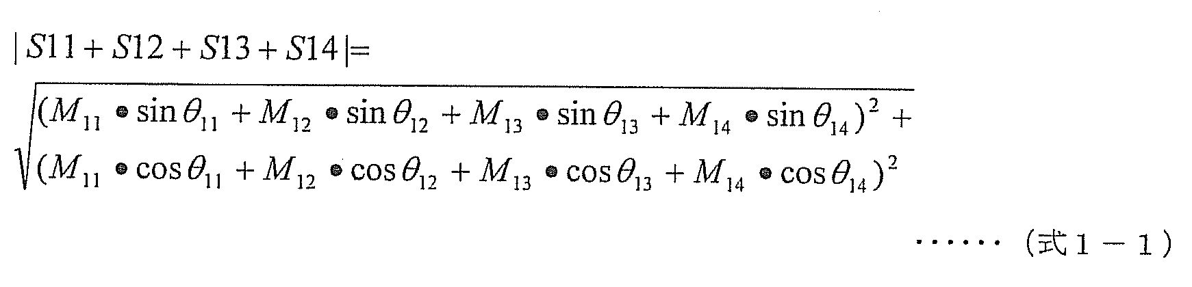
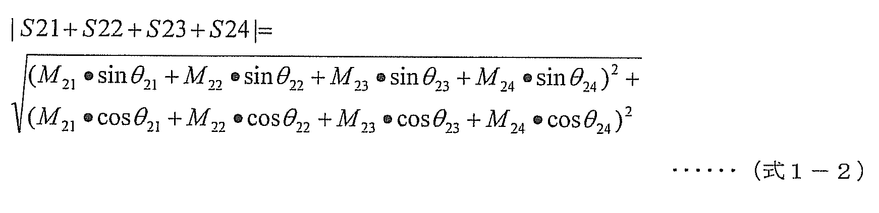
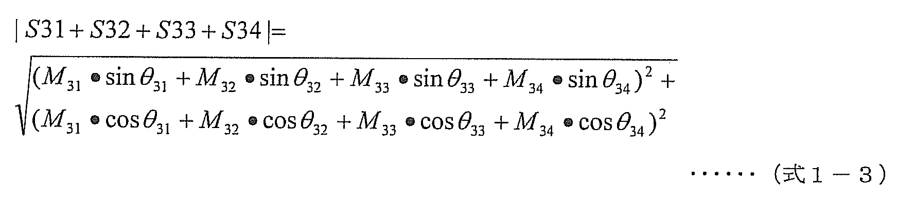
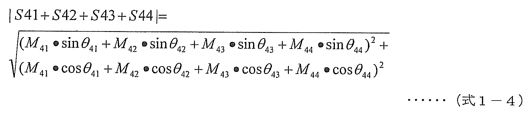
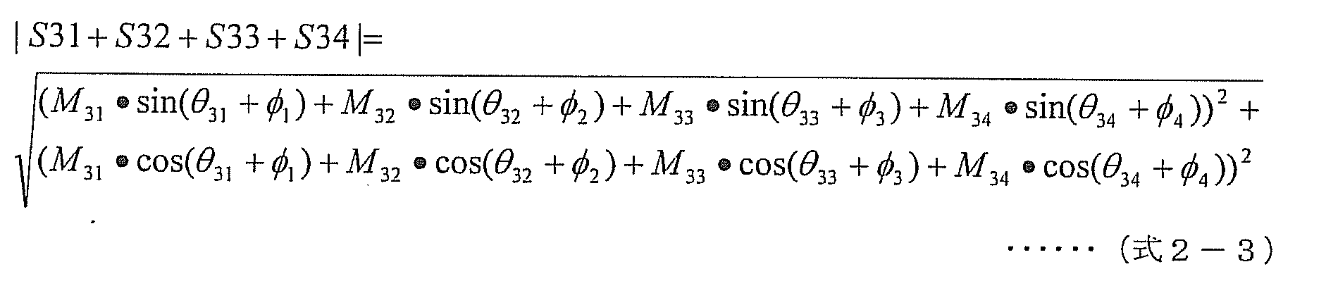
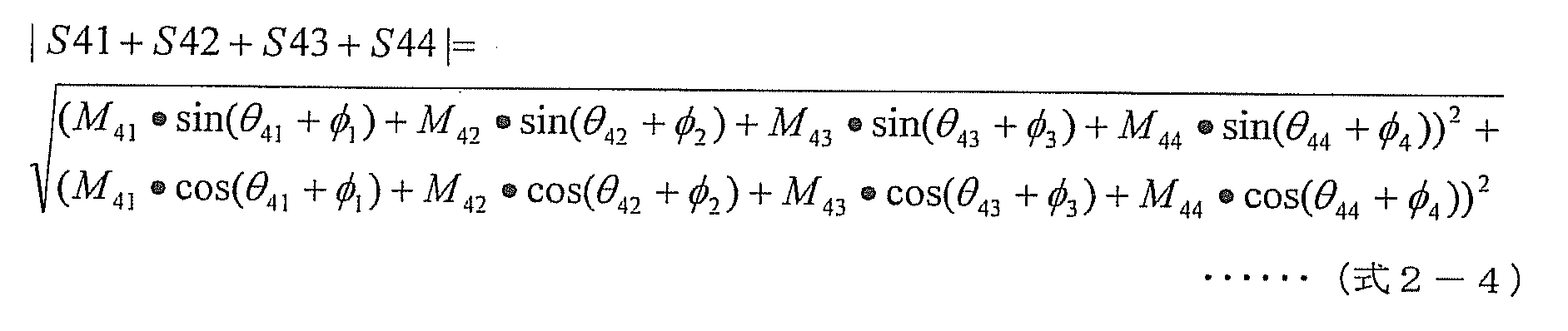
 図12は、本実施形態1に係る高周波加熱装置100の、再サーチ処理の制御手順を示すフローチャートである。
<Re-search process>
FIG. 12 is a flowchart showing the control procedure of the re-search process of the high-frequency heating device 100 according to the first embodiment.
 高周波加熱装置100の制御部110は、加熱処理中に、以下の制御手順により、再サーチ処理を行う。 The control unit 110 of the high-frequency heating device 100 performs a re-search process according to the following control procedure during the heating process.
 図12に示すように、まず、現在加熱処理に使用されている周波数および移相量における、各高周波電力ユニット140a,140b,140c,140dにおける反射電力およびスルー電力の振幅と位相とを、前述した反射電力検出の制御手順およびスルー電力検出の制御手順により検出し、高周波加熱装置100全体の現在の照射効率を算出する(ステップS1501)。 As shown in FIG. 12, first, the amplitude and phase of the reflected power and the through power in each of the high- frequency power units 140a, 140b, 140c, and 140d at the frequency and the amount of phase shift currently used in the heat treatment are described above. Detection is performed by the reflected power detection control procedure and the through power detection control procedure, and the current irradiation efficiency of the entire high-frequency heating device 100 is calculated (step S1501).
 次に、高周波電力発生部120の周波数を、予め定められた再サーチ用周波数になるように制御して(ステップS1502)、前述した反射電力検出の制御手順により、全ての高周波電力ユニット140a,140b,140c,140dにおける、反射電力の振幅と位相とを検出する(ステップS1503)。 Next, the frequency of the high-frequency power generation unit 120 is controlled to be a predetermined frequency for re-search (step S1502), and all the high- frequency power units 140a and 140b are controlled by the above-described reflected power detection control procedure. , 140c and 140d, the amplitude and phase of the reflected power are detected (step S1503).
 続いて、前述した、スルー電力の制御手順により、全ての高周波電力ユニット140a,140b,140c,140dにおける、スルー電力の振幅と位相とを検出する(ステップS1504)。 Subsequently, the amplitude and phase of the through power in all the high- frequency power units 140a, 140b, 140c, and 140d are detected by the above-described through power control procedure (step S1504).
 その後、再サーチ処理において予め定められている全ての周波数において、検出が完了したか否かを判定(ステップS1505)する。完了していない場合(ステップS1505でNo)、高周波電力発生部120に発生させる高周波電力の周波数を、再サーチ用に定められた次の周波数に設定して(ステップS1506)、上記反射電力の振幅と位相を検出する処理(ステップS1503)及びスルー電力の振幅と位相を検出する処理(ステップ1504)を繰り返す。 Thereafter, it is determined whether or not the detection has been completed for all frequencies predetermined in the re-search process (step S1505). If not completed (No in step S1505), the frequency of the high-frequency power to be generated by the high-frequency power generator 120 is set to the next frequency determined for re-search (step S1506), and the amplitude of the reflected power is set. The process for detecting the phase (step S1503) and the process for detecting the amplitude and phase of the through power (step 1504) are repeated.
 これを繰り返して、予め定められた全ての再サーチ用周波数で、全ての高周波電力ユニット140a,140b,140c,140dにおける、反射電力およびスルー電力の振幅と位相とを検出する。 This is repeated to detect the amplitude and phase of the reflected power and the through power in all the high- frequency power units 140a, 140b, 140c, and 140d at all predetermined re-search frequencies.
 全ての再サーチ用周波数で、全ての高周波電力ユニット140a,140b,140c,140dにおける、反射電力およびスルー電力の振幅と位相との検出が完了した(ステップS1505でYes)場合、プレ・サーチ処理で説明した通りに、反射電力およびスルー電力の振幅と位相との情報に基づいて、高周波電力発生部120の周波数と各可変移相部142a,142b,142c,142dの移相量を任意の組み合わせに設定し動作させたと仮定したときの照射ロスを計算により推定する(ステップS1507)。なお、この処理(ステップS1507)での処理内容は、図7に示した周波数ごとに各移相量を変化させた場合の照射効率を推定する処理(ステップS1408)と同様である。 When the detection of the amplitude and phase of the reflected power and the through power in all the high- frequency power units 140a, 140b, 140c, and 140d is completed at all re-search frequencies (Yes in step S1505), the pre-search process is performed. As described, based on the information on the amplitude and phase of the reflected power and the through power, the frequency of the high-frequency power generator 120 and the phase shift amount of each of the variable phase shifters 142a, 142b, 142c, 142d are arbitrarily combined. The irradiation loss when it is assumed that it has been set and operated is estimated by calculation (step S1507). Note that the processing content in this processing (step S1507) is the same as the processing (step S1408) for estimating irradiation efficiency when each phase shift amount is changed for each frequency shown in FIG.
 次に、高周波加熱装置100全体の最良の照射効率の値を算出する(ステップS1508)。 Next, the best irradiation efficiency value of the entire high-frequency heating apparatus 100 is calculated (step S1508).
 そして、再サーチにより算出された高周波加熱装置100全体の最良の照射効率の値(ステップS1508で算出された値)と、先に算出した高周波加熱装置100全体の現在の照射効率の値(ステップS1501で算出された値)とを、それぞれ比較する(ステップS1509)。 Then, the best irradiation efficiency value of the entire high-frequency heating apparatus 100 calculated by the re-search (the value calculated in step S1508) and the current irradiation efficiency value of the entire high-frequency heating apparatus 100 previously calculated (step S1501). Are compared with each other (step S1509).
 ここで、再サーチにより算出した最良の照射効率の値が、先に算出した現在の照射効率の値よりも良好な値となる場合は、再サーチにより算出した最良の照射効率となる周波数および移相量の組み合わせにするように、高周波電力発生部120の周波数、および可変移相部142a~142dの移相量をそれぞれ制御する(ステップS1510)。つまり、高周波電力発生部120の周波数、および可変移相部142a~142dの移相量を更新する。一方、先に算出した現在の照射効率の値が、再サーチにより算出した最良の照射効率の値よりも良好な値となる場合は、再サーチを実行する前の元の周波数にするように、高周波電力発生部120の周波数を制御する(ステップS1511)。 If the best irradiation efficiency value calculated by re-searching is better than the current irradiation efficiency value calculated previously, the frequency and shift at which the best irradiation efficiency is calculated by re-searching. The frequency of the high-frequency power generation unit 120 and the phase shift amounts of the variable phase shift units 142a to 142d are controlled so as to combine the phase amounts (step S1510). That is, the frequency of the high-frequency power generation unit 120 and the phase shift amounts of the variable phase shift units 142a to 142d are updated. On the other hand, when the value of the current irradiation efficiency calculated earlier is a better value than the value of the best irradiation efficiency calculated by the re-search, so that the original frequency before the re-search is performed, The frequency of the high frequency power generation unit 120 is controlled (step S1511).
 なお、再サーチにより算出した、ある周波数および位相条件における最良の照射効率の値が、現在の照射効率の値よりも良好となる場合であっても、たとえば、1つの高周波電力ユニット140における逆流電力の電力値が、予め定められた閾値を超えてしまう条件であれば、選択する必要はない。つまり、各高周波電力ユニット140における逆流電力の電力値が、予め定められた閾値を超えない条件の中で、最良の照射効率となる条件を選び出してもよい。この閾値は、例えば、半導体素子を含んだ増幅器の故障を防ぐために、増幅器が持つ周波数毎の耐電圧特性によって決めればよい。 Even when the best irradiation efficiency value calculated by re-searching under a certain frequency and phase condition is better than the current irradiation efficiency value, for example, the backflow power in one high-frequency power unit 140 It is not necessary to select the power value if the power value exceeds the predetermined threshold value. That is, a condition that provides the best irradiation efficiency may be selected from the conditions in which the power value of the backflow power in each high-frequency power unit 140 does not exceed a predetermined threshold. This threshold value may be determined by the withstand voltage characteristic for each frequency of the amplifier, for example, in order to prevent failure of the amplifier including the semiconductor element.
 これにより、本実施形態に係る高周波加熱装置100は、加熱処理中に被加熱物の温度や形状が変化することにより最適加熱条件が変化した場合でも、再サーチ処理により常に最適加熱条件の下に加熱できる。 As a result, the high-frequency heating device 100 according to the present embodiment is always under the optimum heating condition by the re-search process even when the optimum heating condition changes due to a change in temperature or shape of the object to be heated during the heating process. Can be heated.
 また、高周波加熱装置100全体の最良の照射効率の値を算出する処理(ステップS1508)において最良の照射効率を算出する際、設定周波数において各高周波電力ユニットにおける反射電力およびスルー電力の振幅と位相とを個別に検出した結果を用いて、高周波電力発生部120の周波数と可変移相部の移相量を任意の組み合わせに設定し動作させたと仮定したときの照射ロスを計算し、最も照射効率が良い高周波電力発生部120の周波数の値と各可変移相部142a,142b,142c,142dの移相量の値を決定することができる。これにより、高周波電力発生部120の全ての周波数と各可変移相部142a,142b,142c,142dの全ての移相量の組み合わせを実測した場合と比較すると、上述の例の通りに、大幅な時間短縮が図れる。したがって、再サーチ処理を短時間に行うことができ、被加熱物の温度変化等によって再設定が必要な時間を含めた温め時間の延長を短くでき、ユーザの加熱の待ち時間を軽減できる。 Further, when calculating the best irradiation efficiency in the process of calculating the best irradiation efficiency value of the entire high-frequency heating device 100 (step S1508), the amplitude and phase of reflected power and through power in each high-frequency power unit at the set frequency Is used to calculate the irradiation loss when it is assumed that the frequency of the high-frequency power generation unit 120 and the phase shift amount of the variable phase shift unit are set to an arbitrary combination and operated. The frequency value of the good high-frequency power generation unit 120 and the phase shift amount values of the variable phase shift units 142a, 142b, 142c, and 142d can be determined. Thereby, compared with the case where the combination of all the frequencies of the high frequency electric power generation part 120 and all the phase shift amount of each variable phase shift part 142a, 142b, 142c, 142d is measured, it is large as the above-mentioned example. Time can be shortened. Therefore, the re-search process can be performed in a short time, the extension of the warming time including the time that needs to be reset due to the temperature change of the object to be heated, etc. can be shortened, and the waiting time for heating by the user can be reduced.
 なお、再サーチ処理の開始のタイミングは、加熱処理中に、常時もしくは定期的に、それぞれの高周波電力ユニット140a,140b,140c,140dから、同相検波信号I(1)~I(4)および直交検波信号Q(1)~Q(4)を取り込んで検出した反射電力の振幅と位相とから算出した電力値と、予め定められた閾値とを比較し、少なくとも1つ以上の高周波電力ユニット140における逆流電力の電力値が、その閾値を越えた場合に実行してもよい。 The re-search process is started at the same time or periodically from the respective high- frequency power units 140a, 140b, 140c, and 140d during the heating process, and in-phase detection signals I (1) to I (4) and quadrature. The power value calculated from the amplitude and phase of the reflected power detected by detecting the detection signals Q (1) to Q (4) is compared with a predetermined threshold, and at least one high-frequency power unit 140 You may perform when the electric power value of backflow electric power exceeds the threshold value.
 これにより、加熱処理中に被加熱物の温度や形状が変化することにより、反射電力およびスルー電力の大きさが変化した場合でも、予め閾値を定め、これを超えた場合に再サーチ処理を行うことにより、本実施形態に係る高周波加熱装置100は、常に最適加熱条件の下で被加熱物を加熱できる。 Thus, even when the reflected power and the through power change due to changes in the temperature and shape of the object to be heated during the heat treatment, threshold values are set in advance, and the re-search process is performed when the threshold is exceeded. Thus, the high-frequency heating device 100 according to the present embodiment can always heat the object to be heated under the optimum heating condition.
 なお、前述したプレ・サーチ処理および再サーチ処理を実行する際に、制御部110は、サーチ処理中に過大な反射電力やスルー電力による高周波加熱装置100の故障を防ぐ為に次のようなことしてもよい。特に半導体素子を含んだ増幅器の故障を防ぐ為に次のようなことをしてもよい。具体的には、それぞれの高周波電力ユニット140a,140b,140c,140dから出力される高周波電力の値を、本加熱の際の高周波電力の値よりも小さい値になるように、それぞれの高周波電力増幅部143a,143b,143c,143dの増幅利得を制御してもよい。 When executing the above-described pre-search process and re-search process, the control unit 110 performs the following to prevent failure of the high-frequency heating device 100 due to excessive reflected power or through power during the search process. Also good. In particular, the following may be performed in order to prevent failure of an amplifier including a semiconductor element. Specifically, each high-frequency power amplification is performed so that the value of the high-frequency power output from each high- frequency power unit 140a, 140b, 140c, 140d is smaller than the value of the high-frequency power at the time of main heating. The amplification gains of the units 143a, 143b, 143c, and 143d may be controlled.
 以上のように、本実施形態に係る高周波加熱装置100は、加熱室に収納された被加熱物を加熱する高周波加熱装置であって、設定された周波数の高周波電力を発生する少なくとも一つの高周波電力発生部120と、高周波電力発生部120で発生された高周波電力の位相を変化させる可変移相部142a~142dと、可変移相部142a~142dで位相が変化された高周波電力を加熱室に放射する放射部150、および、放射部150から放射された高周波電力の一部であって加熱室から放射部へ入射する逆流電力を検出する逆流電力検出部である逆流電力検出部とを各々備えた複数の高周波電力ユニット140a~140dと、高周波電力発生部120に周波数を設定し、かつ、可変移相部142a~142dに移相量を設定する制御部110とを備える。なお、逆流電力検出部は、上述したように、方向性結合部144および直交検波部145に相当する。 As described above, the high-frequency heating device 100 according to this embodiment is a high-frequency heating device that heats an object to be heated housed in a heating chamber, and at least one high-frequency power that generates high-frequency power having a set frequency. The generator 120, the variable phase shifters 142a to 142d for changing the phase of the high frequency power generated by the high frequency power generator 120, and the high frequency power whose phase is changed by the variable phase shifters 142a to 142d are radiated to the heating chamber. And a backflow power detection unit which is a part of the high frequency power radiated from the radiation unit 150 and detects a backflow power incident on the radiation unit from the heating chamber. A frequency is set in the plurality of high-frequency power units 140a to 140d and the high-frequency power generation unit 120, and a phase shift amount is set in the variable phase shift units 142a to 142d. And a control unit 110. Note that the backflow power detection unit corresponds to the directional coupling unit 144 and the quadrature detection unit 145 as described above.
 直交検波部145は、制御部110により高周波電力発生部120に設定された周波数に基づいて、一の高周波電力ユニット140の放射部150から放射される高周波電力の一部が反射して当該一の高周波電力ユニット140の放射部150へ入力される反射による逆流電力である反射波の振幅および位相と、他の高周波電力ユニット140の放射部150から放射される高周波電力の一部が一の高周波電力ユニット140の放射部150へ入力される逆流電力であるスルー波の振幅および位相とを検出する。 The quadrature detection unit 145 reflects a part of the high-frequency power radiated from the radiating unit 150 of one high-frequency power unit 140 based on the frequency set in the high-frequency power generation unit 120 by the control unit 110. A high-frequency power in which the amplitude and phase of a reflected wave, which is a backflow power due to reflection, input to the radiating unit 150 of the high-frequency power unit 140 and a part of the high-frequency power radiated from the radiating unit 150 of the other high-frequency power unit 140 are one. The amplitude and phase of the through wave, which is the backflow power input to the radiating unit 150 of the unit 140, are detected.
 制御部110は、高周波電力発生部120に複数の周波数を順次設定し、設定した周波数ごとに各々の高周波電力ユニット140の直交検波部145に反射波の振幅および位相とスルー波の振幅および位相とを検出させ、検出された複数の反射波の振幅および位相とスルー波の振幅および位相とに基づいて、被加熱物を加熱する際の、高周波電力発生部に発生させる高周波電力の周波数および可変移相部における移相量を決定し、決定した周波数および移相量を高周波電力発生部120および可変移相部142a~142dに設定する。 The control unit 110 sequentially sets a plurality of frequencies in the high frequency power generation unit 120, and sets the amplitude and phase of the reflected wave and the amplitude and phase of the through wave in the orthogonal detection unit 145 of each high frequency power unit 140 for each set frequency. Based on the detected amplitude and phase of the plurality of reflected waves and the amplitude and phase of the through wave, the frequency and variable shift of the high-frequency power generated in the high-frequency power generation unit when heating the object to be heated are detected. The phase shift amount in the phase part is determined, and the determined frequency and phase shift amount are set in the high-frequency power generation unit 120 and the variable phase shift units 142a to 142d.
 これにより、実測により得られた第1~第4の高周波電力ユニット140a~140dのそれぞれにおける照射ロスから、可変移相部142a~142dの移相量の組み合わせを変えた場合の第1~第4の高周波電力ユニット140a~140dのそれぞれにおける照射ロスを、短時間で求めることができる。その結果、ユーザが高周波加熱装置100の使用開始ボタンを押して実際に本加熱処理を行う前に、最適な周波数および移相量の組み合わせを短時間に決定することができ、ユーザの利便性を向上させる。 Thus, the first to fourth when the combination of the phase shift amounts of the variable phase shifters 142a to 142d is changed from the irradiation loss in each of the first to fourth high frequency power units 140a to 140d obtained by actual measurement. Irradiation loss in each of the high-frequency power units 140a to 140d can be obtained in a short time. As a result, before the user actually presses the use start button of the high-frequency heating device 100 and actually performs the main heat treatment, the optimum combination of the frequency and the amount of phase shift can be determined in a short time, thereby improving user convenience. Let
 また、実施形態1の構成によると、高周波加熱装置100が1つの高周波電力発生部120を有し、すべての高周波電力ユニット140が同じ周波数で動作するため、加熱の条件を決定するパラメータが少なくて済む。つまり、高周波電力発生部120の周波数のみを変化させて実測すればよいので、実測の回数を抑え、単純な制御で加熱条件を決定することができる。その結果、非常に短時間でプレ・サーチ処理および再サーチ処理を行うことができる。 In addition, according to the configuration of the first embodiment, the high-frequency heating device 100 includes one high-frequency power generation unit 120, and all the high-frequency power units 140 operate at the same frequency, so there are few parameters that determine the heating conditions. That's it. That is, since only the frequency of the high-frequency power generating unit 120 needs to be actually measured, the number of times of actual measurement can be suppressed and the heating condition can be determined by simple control. As a result, the pre-search process and the re-search process can be performed in a very short time.
 (実施形態2)
 本実施形態に係る高周波加熱装置は、実施形態1に係る高周波加熱装置100が1つの高周波電力発生部120を有しているのに対し、2つの高周波電力発生部を有している点が異なる。この構成により、2つの高周波電力発生部の周波数を個別に設定することにより、最大照射効率を更に高めることができる。
(Embodiment 2)
The high-frequency heating device according to the present embodiment is different from the high-frequency heating device 100 according to the first embodiment in that the high-frequency heating device 100 includes two high-frequency power generation units, whereas the high-frequency heating device 100 includes one high-frequency power generation unit 120. . With this configuration, the maximum irradiation efficiency can be further increased by individually setting the frequencies of the two high-frequency power generation units.
 以下、本実施形態に係る高周波加熱装置について、実施形態1に係る高周波加熱装置100との相違点を中心に、図面を参照しながら説明する。なお、本実施形態2の説明において、前述の実施形態1と同じ機能を有する構成要素には同じ参照符号を付し、説明を省略する。また、前述の実施形態1と同じ作用を有する内容についても、説明を省略する。 Hereinafter, the high-frequency heating device according to the present embodiment will be described with reference to the drawings, focusing on differences from the high-frequency heating device 100 according to the first embodiment. In the description of the second embodiment, components having the same functions as those of the first embodiment are denoted by the same reference numerals, and the description thereof is omitted. Further, description of the content having the same action as that of the first embodiment will be omitted.
 図13は、本発明の実施形態2に係る、高周波加熱装置の構成を示すブロック図である。 FIG. 13 is a block diagram showing a configuration of a high-frequency heating device according to Embodiment 2 of the present invention.
 同図に示す高周波加熱装置200は、図1に示した実施形態1に係る高周波加熱装置100と比較して、高周波電力発生部120に代わり第1の高周波電力発生部220aと第2の高周波電力発生部220bとを備え、分配部130に代わり第1の分配部230aと第2の分配部230bとを備え、制御部110に代わり制御部210を備える。 The high-frequency heating device 200 shown in the figure is different from the high-frequency heating device 100 according to the first embodiment shown in FIG. 1 in that the first high-frequency power generation unit 220a and the second high-frequency power are used instead of the high-frequency power generation unit 120. A generation unit 220b, a first distribution unit 230a and a second distribution unit 230b instead of the distribution unit 130, and a control unit 210 instead of the control unit 110.
 第1の高周波電力発生部220aは、制御部210から入力される周波数制御信号Cfreq1で設定された周波数の高周波電力を発生する。発生された高周波電力は、第1の分配部230aで分配され、第1の高周波電力ユニット140aおよび第2の高周波電力ユニット140bへ入力される。つまり、第1の高周波電力発生部220aは、第1および第2の高周波電力ユニット140aおよび140bへ高周波電力を供給する。 The first high frequency power generation unit 220a generates high frequency power having a frequency set by the frequency control signal Cfreq1 input from the control unit 210. The generated high frequency power is distributed by the first distribution unit 230a and input to the first high frequency power unit 140a and the second high frequency power unit 140b. That is, the first high frequency power generation unit 220a supplies high frequency power to the first and second high frequency power units 140a and 140b.
 第2の高周波電力発生部220bは、制御部210から入力される周波数制御信号Cfreq2で設定された周波数の高周波電力を発生する。発生された高周波電力は、第2の分配部230bで分配され、第3の高周波電力ユニット140cおよび第4の高周波電力ユニット140dへ入力される。つまり、第2の高周波電力発生部220bは、第3および第4の高周波電力ユニット140cおよび140dへ高周波電力を供給する。なお、以下、第1の高周波電力発生部220aおよび第2の高周波電力発生部220bを、それぞれ、高周波電力発生部220aおよび高周波電力発生部220bと記載する場合がある。 The second high frequency power generation unit 220b generates high frequency power having a frequency set by the frequency control signal Cfreq2 input from the control unit 210. The generated high frequency power is distributed by the second distribution unit 230b and input to the third high frequency power unit 140c and the fourth high frequency power unit 140d. That is, the second high frequency power generation unit 220b supplies high frequency power to the third and fourth high frequency power units 140c and 140d. Hereinafter, the first high frequency power generation unit 220a and the second high frequency power generation unit 220b may be referred to as a high frequency power generation unit 220a and a high frequency power generation unit 220b, respectively.
 制御部210は、図1に示した制御部110と比較して、2つの高周波電力発生部つまり第1の高周波電力発生部220aおよび第2の高周波電力発生部220bへ、周波数制御信号Cfreq1および周波数制御信号Cfreq2を出力する。これにより、制御部210は、第1の高周波電力発生部220aに発生させる高周波電力の周波数および第2の高周波電力発生部220bに発生させる高周波電力の周波数を、互いに独立に設定する。なお、周波数を互いに独立に設定するとは、第1の高周波電力発生部220aに発生させる高周波電力の周波数と、第2の高周波電力発生部220bに発生させる高周波電力の周波数とは依存しないことである。つまり、これら2つの高周波電力の周波数は同じであっても、異なっていてもよい。 Compared with the control unit 110 shown in FIG. 1, the control unit 210 supplies the frequency control signal Cfreq1 and the frequency to the two high-frequency power generation units, that is, the first high-frequency power generation unit 220a and the second high-frequency power generation unit 220b. A control signal Cfreq2 is output. Thereby, the control part 210 sets the frequency of the high frequency electric power generated in the 1st high frequency electric power generation part 220a and the frequency of the high frequency electric power generated in the 2nd high frequency electric power generation part 220b mutually independently. Note that setting the frequencies independently from each other means that the frequency of the high-frequency power generated by the first high-frequency power generation unit 220a and the frequency of the high-frequency power generated by the second high-frequency power generation unit 220b do not depend on each other. . That is, the frequency of these two high-frequency powers may be the same or different.
 本実施形態に係る高周波加熱装置200の基本的な制御手順は、前述の実施形態1で説明した高周波加熱装置100の基本的な制御手順と同様である。ただし、前述の図1で説明した高周波加熱装置100は、全ての高周波電力ユニット140a,140b,140c,140dは同じ周波数で動作するのに対して、本実施形態の図13に示す高周波加熱装置200においては、第1,第2の高周波電力ユニット140a,140bは、第1の高周波電力発生部220aの周波数で動作し、第3,第4の高周波電力ユニット140c,140dは、第2の高周波電力発生部220bの周波数で動作する。 The basic control procedure of the high-frequency heating device 200 according to this embodiment is the same as the basic control procedure of the high-frequency heating device 100 described in the first embodiment. However, in the high-frequency heating device 100 described with reference to FIG. 1, all the high- frequency power units 140a, 140b, 140c, and 140d operate at the same frequency, whereas the high-frequency heating device 200 shown in FIG. 13 of the present embodiment. , The first and second high- frequency power units 140a and 140b operate at the frequency of the first high-frequency power generator 220a, and the third and fourth high- frequency power units 140c and 140d It operates at the frequency of the generator 220b.
 これにより、各高周波電力発生部(第1の高周波電力発生部220aおよび第2の高周波電力発生部220b)の周波数を実際に変化させて高周波電力を放射させた場合に、直交検波部145a、145b、145c、145dにおいて検出された同相検波信号I(1)~I(4)と直交検波信号Q(1)~Q(4)とから、高周波電力発生部220aおよび220bのそれぞれにおける周波数の組み合わせに対応する、反射による逆流電力の振幅および位相と通り抜けによる逆流電力の振幅および位相を検出する(求める)ことができる。 Accordingly, when the high frequency power is radiated by actually changing the frequency of each high frequency power generation unit (the first high frequency power generation unit 220a and the second high frequency power generation unit 220b), the quadrature detection units 145a and 145b are used. From the in-phase detection signals I (1) to I (4) and quadrature detection signals Q (1) to Q (4) detected at 145c and 145d, the frequency combinations in the high-frequency power generation units 220a and 220b are obtained. Corresponding amplitude and phase of backflow power due to reflection and backflow power amplitude and phase due to passing through can be detected (determined).
 周波数の組み合わせにごとに、検出された反射電力の振幅および位相とスルー電力の振幅および位相との値を用いて、移相量を任意の組み合わせに設定し動作させたと仮定したときの照射ロスを計算して、計算結果から最も高周波加熱装置200全体の照射効率が良い周波数の組み合わせと、移相量の組み合わせとを決定することができる。すなわち、それぞれの高周波電力発生部220aおよび220bの周波数と、各々の可変移相部142a,142b,142c,142dの移相量のすべての組み合わせにおいて実際に測定することなく、最低限の実測値から最適な照射効率を計算で求めることができる。よって、時間がかかる実測を少なくすることができる。これにより、ユーザが高周波加熱装置の加熱をスタートしてから実際に加熱が始まる前までの高効率の照射を見つけるための準備時間を短くすることができる。 For each frequency combination, using the values of the detected reflected power amplitude and phase and the through power amplitude and phase, the irradiation loss when assuming that the phase shift amount is set to an arbitrary combination and operated. By calculating, it is possible to determine a combination of frequencies with the best irradiation efficiency of the entire high-frequency heating apparatus 200 and a combination of phase shift amounts from the calculation result. That is, from the actual measurement value without actually measuring all the combinations of the frequencies of the respective high-frequency power generation units 220a and 220b and the phase shift amounts of the respective variable phase shift units 142a, 142b, 142c, and 142d. The optimal irradiation efficiency can be obtained by calculation. Therefore, time-consuming actual measurement can be reduced. Thereby, it is possible to shorten the preparation time for finding high-efficiency irradiation from when the user starts heating the high-frequency heating device to before the heating actually starts.
 高周波電力発生部220aおよび220bの具体的な構成は、前述した実施形態1で説明した、図2に示す高周波電力発生部120の具体的な構成と同一であるので、説明は省略する。 The specific configuration of the high-frequency power generation units 220a and 220b is the same as the specific configuration of the high-frequency power generation unit 120 shown in FIG.
 なお、図13において、高周波加熱装置200は、2つの高周波電力発生部(第1の高周波電力発生部220aおよび第2の高周波電力発生部220b)と、4つの高周波電力ユニット(第1の高周波電力ユニット140a、第2の高周波電力ユニット140b、第3の高周波電力ユニット140cおよび第4の高周波電力ユニット140d)で構成されているが、高周波電力発生部および高周波電力ユニットの数はこれに限定されるものではなく、複数の高周波電力発生部および複数の高周波電力ユニットを有していればよい。 In FIG. 13, the high-frequency heating device 200 includes two high-frequency power generation units (first high-frequency power generation unit 220a and second high-frequency power generation unit 220b) and four high-frequency power units (first high-frequency power generation unit). Unit 140a, second high-frequency power unit 140b, third high-frequency power unit 140c, and fourth high-frequency power unit 140d), but the number of high-frequency power generation units and high-frequency power units is limited to this. What is necessary is just to have a some high frequency electric power generation part and a some high frequency electric power unit instead of a thing.
 <反射電力の検出方法>
 図14は、本実施形態2に係る高周波加熱装置200の、反射電力検出の制御手順を示すフローチャートである。
<Detection method of reflected power>
FIG. 14 is a flowchart showing a control procedure of reflected power detection of the high-frequency heating device 200 according to the second embodiment.
 高周波加熱装置200の制御部210は、以下の制御手順により、それぞれの高周波電力ユニット140a,140b,140c,140dの反射電力の検出を行う。 The control unit 210 of the high-frequency heating device 200 detects the reflected power of each of the high- frequency power units 140a, 140b, 140c, and 140d according to the following control procedure.
 同図に示す反射電力検出方法は、図5に示した実施形態1の反射電力の検出方法と比較して、第1の高周波電力発生部220aおよび第2の高周波電力発生部220bが、異なる周波数で動作している場合と、同一の周波数で動作している場合とで、処理を分けている点が異なる。 The reflected power detection method shown in FIG. 5 differs from the reflected power detection method of the first embodiment shown in FIG. 5 in that the first high-frequency power generation unit 220a and the second high-frequency power generation unit 220b have different frequencies. The processing is different between the case of operating at the same frequency and the case of operating at the same frequency.
 まず、第1の高周波電力発生部220aと第2の高周波電力発生部220bとで、発生されている高周波電力の周波数が互いに異なるか否かを判定する(ステップS2101)。 First, it is determined whether the frequency of the generated high frequency power is different between the first high frequency power generation unit 220a and the second high frequency power generation unit 220b (step S2101).
 第1の高周波電力発生部220aおよび第2の高周波電力発生部220bが異なる周波数で動作している場合(ステップS2101でYes)は、制御部210は、同一の周波数で動作している高周波電力ユニットのグループに分けて、それぞれの高周波電力ユニットの反射電力を検出する。言い換えると、第1の高周波電力発生部220aから高周波電力を供給される第1の高周波電力ユニット140aおよび第2の高周波電力ユニット140bと、第2の高周波電力発生部220bから高周波電力を供給される第3の高周波電力ユニット140cおよび第4の高周波電力ユニット140dとに分ける。 When the first high-frequency power generation unit 220a and the second high-frequency power generation unit 220b are operating at different frequencies (Yes in step S2101), the control unit 210 is operating at the same frequency. And the reflected power of each high-frequency power unit is detected. In other words, the first high frequency power unit 140a and the second high frequency power unit 140b supplied with the high frequency power from the first high frequency power generation unit 220a and the high frequency power from the second high frequency power generation unit 220b are supplied. It is divided into a third high-frequency power unit 140c and a fourth high-frequency power unit 140d.
 まず、第1の高周波電力発生部220aで発生された高周波電力を放射する高周波電力ユニット140aおよび140bのグループにおける、それぞれの高周波電力ユニット140aおよび140bの反射電力を検出する手順を説明する。 First, a procedure for detecting the reflected power of each of the high- frequency power units 140a and 140b in the group of the high- frequency power units 140a and 140b that radiates the high-frequency power generated by the first high-frequency power generation unit 220a will be described.
 図14に示すように、制御部210は、反射電力を検出しようとする1つの高周波電力ユニット140(例えば、第1の高周波電力ユニット140a)以外の高周波電力ユニット140(例えば、第2の高周波電力ユニット140b)の出力電力のレベルが、反射電力を検出しようとする高周波電力ユニット140(例えば、第1の高周波電力ユニット140a)の反射電力の検出に影響を与えないレベルになるよう制御する(ステップS2102)。 As shown in FIG. 14, the control unit 210 has a high-frequency power unit 140 (for example, the second high-frequency power) other than one high-frequency power unit 140 (for example, the first high-frequency power unit 140a) to detect the reflected power. The level of the output power of the unit 140b) is controlled so as not to affect the detection of the reflected power of the high-frequency power unit 140 (for example, the first high-frequency power unit 140a) that attempts to detect the reflected power (step) S2102).
 次に、反射電力を検出しようとする高周波電力ユニット140以外の高周波電力ユニット140(例えば、第2の高周波電力ユニット140b)の、高周波電力増幅部143の増幅利得を制御した後、制御部210は、反射電力を検出しようとする高周波電力ユニット140(例えば、第1の高周波電力ユニット140a)の同相検波信号Iおよび直交検波信号Qを取り込み、逆流電力の振幅と位相とを検出する(ステップS2103)。 Next, after controlling the amplification gain of the high-frequency power amplification unit 143 of the high-frequency power unit 140 (for example, the second high-frequency power unit 140b) other than the high-frequency power unit 140 that attempts to detect the reflected power, the control unit 210 The in-phase detection signal I and the quadrature detection signal Q of the high-frequency power unit 140 (for example, the first high-frequency power unit 140a) to detect the reflected power are captured, and the amplitude and phase of the backflow power are detected (step S2103). .
 これにより、例えば、第1の高周波電力ユニット140aの反射電力の振幅および位相を検出する。 Thereby, for example, the amplitude and phase of the reflected power of the first high-frequency power unit 140a are detected.
 次に、第1の高周波電力発生部220aに対応する全ての高周波電力ユニット140(例えば、第1および第2の高周波電力ユニット140aおよび140b)において、反射電力の検出が完了したか否かを判定する(ステップS2104)。完了していない場合(ステップS2104でNo)、別の高周波電力ユニットを検出対象として(ステップS2105)上記の検出対象とした1つの高周波電力ユニット140以外の高周波電力ユニット140の出力電圧を下げる処理(ステップS2102)および当該検出対象とした高周波電力ユニット140における逆流電力の振幅と位相を検出する処理(ステップS2103)を繰り返す。 Next, it is determined whether or not the detection of the reflected power is completed in all the high-frequency power units 140 (for example, the first and second high- frequency power units 140a and 140b) corresponding to the first high-frequency power generation unit 220a. (Step S2104). If not completed (No in step S2104), another high-frequency power unit is set as a detection target (step S2105), and the output voltage of the high-frequency power unit 140 other than one high-frequency power unit 140 set as the detection target is reduced ( Step S2102) and the process (step S2103) of detecting the amplitude and phase of the backflow power in the high-frequency power unit 140 as the detection target are repeated.
 一方、第1の高周波電力発生部220aに対応する全ての高周波電力ユニット140において、反射電力の検出が完了した場合(ステップS2104でYes)、第1の高周波電力発生部220aで発生された高周波電力を放射する高周波電力ユニット140のグループにおける反射電力の振幅および位相の検出を終了する。 On the other hand, when the detection of the reflected power is completed in all the high-frequency power units 140 corresponding to the first high-frequency power generation unit 220a (Yes in step S2104), the high-frequency power generated by the first high-frequency power generation unit 220a. The detection of the amplitude and phase of the reflected power in the group of the high-frequency power unit 140 that radiates is terminated.
 このとき、ステップS2102~S2105の処理と並行して、同様の手順で、第2の高周波電力発生部220bで発生された高周波電力を放射する第3および第4の高周波電力ユニット140cおよび140dそれぞれの反射電力を検出する(ステップS2110~S2112)。 At this time, in parallel with the processing of steps S2102 to S2105, the third and fourth high- frequency power units 140c and 140d that radiate the high-frequency power generated by the second high-frequency power generation unit 220b in the same procedure, respectively. The reflected power is detected (steps S2110 to S2112).
 この時、それぞれのグループは動作している周波数が異なるので、反射電力の検出においてはグループ間の相互の干渉が発生しない。従って、それぞれのグループ毎の反射電力検出の手順(S2101からS2105の手順と、S2110からS2113の手順)は、並行して同時に実施できる。 At this time, since each group operates at different frequencies, mutual interference between the groups does not occur in the detection of reflected power. Therefore, the reflected power detection procedure for each group (the procedure from S2101 to S2105 and the procedure from S2110 to S2113) can be performed simultaneously in parallel.
 これにより、本実施形態に係る高周波加熱装置200は、第1~第4の高周波電力ユニット140a,140b,140c,140dに於ける反射電力の振幅と位相を検出するのに要する時間を短縮することができ、後述するプレ・サーチ処理、および再サーチ処理の実行に要する時間も短縮され、ユーザの加熱開始の指示から加熱処理完了までの時間を、実施形態1に係る高周波加熱装置100と比較して、より短縮することができる。 Thereby, the high-frequency heating device 200 according to the present embodiment reduces the time required to detect the amplitude and phase of the reflected power in the first to fourth high- frequency power units 140a, 140b, 140c, and 140d. The time required for executing the pre-search process and the re-search process, which will be described later, is shortened, and the time from the user's instruction to start heating to the completion of the heating process is compared with that of the high-frequency heating device 100 according to the first embodiment. Thus, it can be further shortened.
 一方、第1の高周波電力発生部220aおよび第2の高周波電力発生部220bが同一の周波数で動作している場合(ステップS2101でNo)は、第1~第4の高周波電力ユニット140a,140b,140c,140dすべてが同一の周波数で動作している状態となり、制御部210が反射電力を検出する手順は、前述した実施形態1の反射電力検出の制御手順(図5)と同様の手順となる(ステップS1201~S1204)。 On the other hand, when the first high-frequency power generator 220a and the second high-frequency power generator 220b are operating at the same frequency (No in step S2101), the first to fourth high- frequency power units 140a, 140b, 140c and 140d are all operating at the same frequency, and the procedure for the controller 210 to detect the reflected power is the same as the reflected power detection control procedure (FIG. 5) of the first embodiment described above. (Steps S1201 to S1204).
 <スルー電力の検出方法>
 図15は、本実施形態2に係る高周波加熱装置200のスルー電力検出の制御手順を示すフローチャートである。
<Through power detection method>
FIG. 15 is a flowchart illustrating a control procedure of through power detection of the high-frequency heating device 200 according to the second embodiment.
 高周波加熱装置200の制御部210は、以下の制御手順により、それぞれの高周波電力ユニット140a,140b,140c,140d間相互のスルー電力の検出を行う。 The control unit 210 of the high-frequency heating device 200 detects through power between the high- frequency power units 140a, 140b, 140c, and 140d according to the following control procedure.
 同図に示すスルー電力の検出方法は、図6に示した実施形態1のスルー電力の検出方法と比較して、第1の高周波電力発生部220aおよび第2の高周波電力発生部220bが、異なる周波数で動作している場合と、同一の周波数で動作している場合とで処理を分けている点が異なる。 The through power detection method shown in the figure differs from the through power detection method of the first embodiment shown in FIG. 6 in the first high frequency power generation unit 220a and the second high frequency power generation unit 220b. The difference is that processing is divided between the case of operating at a frequency and the case of operating at the same frequency.
 まず、第1の高周波電力発生部220aと第2の高周波電力発生部220bとで、発生されている高周波電力の周波数が互いに異なるか否かを判定する(ステップS2201)。 First, it is determined whether the frequency of the generated high frequency power is different between the first high frequency power generation unit 220a and the second high frequency power generation unit 220b (step S2201).
 第1の高周波電力発生部220aおよび第2の高周波電力発生部220bが異なる周波数で動作している場合(ステップS2201でYes)は、制御部210は、まず、1つの高周波電力ユニット140(例えば、第1の高周波電力ユニット140a)のみ高周波電力を出力する。そして、制御部210は、他の高周波電力ユニット140(例えば、第2,第3,および第4の高周波電力ユニット140b,140c,140d)の出力電力を、各高周波電力ユニット140における反射電力の検出レベルが充分に小さくなるように、それぞれの高周波電力ユニット140の高周波電力増幅部143の増幅利得を制御する(ステップS2202)。 When the first high-frequency power generation unit 220a and the second high-frequency power generation unit 220b are operating at different frequencies (Yes in step S2201), the control unit 210 first selects one high-frequency power unit 140 (for example, Only the first high-frequency power unit 140a) outputs high-frequency power. The control unit 210 detects the output power of the other high-frequency power units 140 (for example, the second, third, and fourth high- frequency power units 140b, 140c, and 140d) and detects the reflected power in each high-frequency power unit 140. The amplification gain of the high-frequency power amplifier 143 of each high-frequency power unit 140 is controlled so that the level is sufficiently small (step S2202).
 次に、制御部210は、高周波電力を出力する1つの高周波電力ユニット140(例えば、第1の高周波電力ユニット140a)に対応する高周波電力発生部120(例えば、第1の高周波電力発生部220a)の周波数を、当該高周波電力発生部120と異なる周波数に設定されている高周波電力発生部220(例えば、第2の高周波電力発生部220b)の周波数に設定する。 Next, the control unit 210 has a high frequency power generation unit 120 (for example, the first high frequency power generation unit 220a) corresponding to one high frequency power unit 140 (for example, the first high frequency power unit 140a) that outputs the high frequency power. Is set to the frequency of the high frequency power generation unit 220 (for example, the second high frequency power generation unit 220b) set to a frequency different from that of the high frequency power generation unit 120.
 続いて、高周波電力の出力レベルを小さくするように制御された他の高周波電力ユニット140の同相検波信号Iおよび直交検波信号Qを取り込み、逆流電力の振幅および位相を検出する(ステップS2204)。これにより、高周波電力が出力されている1つの高周波電力ユニット140から、他のそれぞれの高周波電力ユニット140へのスルー電力(例えば、第1の高周波電力ユニット140aから第2の高周波電力ユニット140b、第3の高周波電力ユニット140cへのスルー電力、および第4の高周波電力ユニット140dへのスルー電力)の振幅と位相とを検出できる。 Subsequently, the in-phase detection signal I and the quadrature detection signal Q of another high-frequency power unit 140 controlled to reduce the output level of the high-frequency power are taken in, and the amplitude and phase of the backflow power are detected (step S2204). Thus, through power from one high-frequency power unit 140 to which high-frequency power is output to each of the other high-frequency power units 140 (for example, the first high-frequency power unit 140a to the second high-frequency power unit 140b, the first The amplitude and phase of the through power to the third high frequency power unit 140c and the through power to the fourth high frequency power unit 140d can be detected.
 高周波電力の出力レベルを小さくするように制御した、他の高周波電力ユニット140(例えば、第2,第3,および第4の高周波電力ユニット140b,140c,140d)の同相検波信号I(2)~I(4)および直交検波信号Q(2)~Q(4)の取り込みが完了したら、周波数の設定を変更した高周波電力発生部(例えば、第2の高周波電力発生部220b)の周波数を変更する前の周波数に設定する(ステップS2205)。ただし、引き続き高周波電力ユニット間相互のスルー電力の他の組合せを検出する場合、次回のスルー電力検出手順の際に、高周波電力を出力する1つの高周波電力ユニットが、今回の高周波電力を出力する1つの高周波電力ユニット(例えば、第1の高周波電力ユニット140a)と同一の周波数で動作している高周波電力ユニット(例えば、第2の高周波電力ユニット140b)である場合には、周波数の設定を変更した高周波電力発生部(例えば、第2の高周波電力発生部220b)の周波数を変更する前の周波数に設定する処理(ステップS2205)は、スキップしてもよい。 In-phase detection signals I (2) to I (2) to other high-frequency power units 140 (for example, second, third, and fourth high- frequency power units 140b, 140c, and 140d) that are controlled to reduce the output level of the high-frequency power. When the acquisition of I (4) and quadrature detection signals Q (2) to Q (4) is completed, the frequency of the high frequency power generation unit (for example, the second high frequency power generation unit 220b) whose frequency setting has been changed is changed. The previous frequency is set (step S2205). However, when another through power combination between the high frequency power units is continuously detected, one high frequency power unit that outputs the high frequency power outputs the current high frequency power during the next through power detection procedure. In the case of a high-frequency power unit (for example, the second high-frequency power unit 140b) operating at the same frequency as two high-frequency power units (for example, the first high-frequency power unit 140a), the frequency setting is changed. The process of setting the frequency of the high frequency power generation unit (for example, the second high frequency power generation unit 220b) to the frequency before changing (step S2205) may be skipped.
 全ての高周波電力ユニット140からのスルー電力の検出が完了したか否かを判定し(ステップS2206)、完了していない場合(ステップS2206でNo)、別の高周波電力ユニット140を検出対象として(ステップS2207)、上記の検出対象とした1つの高周波電力ユニット140以外の高周波電力ユニット140の出力電圧を下げる処理(ステップS2202)から高周波電力発生部の周波数を元の周波数に設定する処理(ステップS2205)までを繰り返す。 It is determined whether or not detection of through power from all the high-frequency power units 140 has been completed (step S2206). If not completed (No in step S2206), another high-frequency power unit 140 is set as a detection target (step S2206). S2207) The process of setting the frequency of the high-frequency power generation unit to the original frequency (step S2205) from the process of reducing the output voltage of the high-frequency power units 140 other than the one high-frequency power unit 140 as the detection target (step S2202). Repeat until.
 一方、全ての高周波電力ユニット140からのスルー電力の検出が完了した場合(ステップS2206でYes)、このスルー電力検出処理を終了する。 On the other hand, when the detection of through power from all the high-frequency power units 140 is completed (Yes in step S2206), the through power detection process is terminated.
 これにより、全ての高周波電力ユニット140間における相互のスルー電力の振幅と位相とを検出できる。 Thereby, the amplitude and phase of the mutual through power between all the high-frequency power units 140 can be detected.
 一方、第1の高周波電力発生部220a第2の高周波電力発生部220bが同一の周波数で動作している場合(ステップS2201でNo)は、全ての高周波電力ユニット140a,140b,140c,140dが同一の周波数で動作している状態となる。このとき、制御部210がスルー電力を検出する手順は、図6に示した実施形態1のスルー電力検出の制御手順と同様である。 On the other hand, when the first high-frequency power generation unit 220a and the second high-frequency power generation unit 220b are operating at the same frequency (No in step S2201), all the high- frequency power units 140a, 140b, 140c, and 140d are the same. It becomes the state which operates with the frequency of. At this time, the procedure of detecting the through power by the control unit 210 is the same as the control procedure of the through power detection of the first embodiment shown in FIG.
 <プレ・サーチ処理>
 図16は、本実施形態2に係る高周波加熱装置200の、本加熱前における最適加熱条件の決定処理(プレ・サーチ処理)の制御手順を示すフローチャートである。
<Pre-search process>
FIG. 16 is a flowchart showing a control procedure of the optimum heating condition determination process (pre-search process) before the main heating in the high-frequency heating device 200 according to the second embodiment.
 同図に示すプレ・サーチ処理は、図7に示した実施形態1におけるプレ・サーチ処理とほぼ同じであるが、第1の高周波電力発生部220aおよび第2の高周波電力発生部220bに独立に周波数を設定する点が異なる。 The pre-search process shown in the figure is almost the same as the pre-search process in the first embodiment shown in FIG. 7, but the first high-frequency power generator 220a and the second high-frequency power generator 220b are independent of each other. The frequency setting is different.
 高周波加熱装置200の制御部210は、加熱処理前に、以下の制御手順により、プレ・サーチ処理を行う。なお、以下、第1の高周波電力発生部220aを単に高周波電力発生部220a、第2の高周波電力発生部220bを単に高周波電力発生部220bと記載する。 The control unit 210 of the high-frequency heating device 200 performs a pre-search process according to the following control procedure before the heating process. Hereinafter, the first high-frequency power generation unit 220a is simply referred to as a high-frequency power generation unit 220a, and the second high-frequency power generation unit 220b is simply referred to as a high-frequency power generation unit 220b.
 図16に示すように、まず、それぞれの高周波電力発生部220aおよび220bの周波数を、予め定められたプレ・サーチ用初期周波数(例えば、第1の高周波電力発生部220aは周波数A0,第2の高周波電力発生部220bは周波数B0)にするように、それぞれの高周波電力発生部220aおよび220bの周波数を制御する(ステップS2301)。 As shown in FIG. 16, first, the frequency of each of the high-frequency power generation units 220a and 220b is set to a predetermined pre-search initial frequency (for example, the first high-frequency power generation unit 220a has the frequency A0, the second frequency The high-frequency power generation unit 220b controls the frequency of each of the high-frequency power generation units 220a and 220b so as to set the frequency B0) (step S2301).
 次に、前述した反射電力検出の制御手順により、全ての高周波電力ユニット140a,140b,140c,140dにおける、反射電力の振幅と位相とを検出する(ステップS2302)。 Next, the amplitude and phase of the reflected power in all the high- frequency power units 140a, 140b, 140c, 140d are detected by the above-described reflected power detection control procedure (step S2302).
 全ての高周波電力ユニット140a,140b,140c,140dにおける、反射電力の検出が完了したら、つぎに、プレ・サーチ処理において予め定められている全ての周波数において、反射電力の振幅および位相が検出されたか否かを判定する(ステップS2303)。 When the detection of the reflected power in all the high- frequency power units 140a, 140b, 140c, and 140d is completed, whether the amplitude and phase of the reflected power have been detected at all the frequencies predetermined in the pre-search process. It is determined whether or not (step S2303).
 全ての周波数において反射電力の振幅および位相が検出されていない場合(ステップS2303でNo)、制御部210は、それぞれの高周波電力発生部220a,220bの周波数を、プレ・サーチ用に予め定められた次の周波数(例えば、第1の高周波電力発生部220aは周波数A1,第2の高周波電力発生部220bは周波数B1)にするように、それぞれの高周波電力発生部220a,220bの周波数を制御する(ステップS2304)。そして、プレ・サーチ用に予め定められた次の周波数で、上記反射電力の振幅と位相とを検出する処理(ステップS2302)を繰り返す。 When the amplitude and phase of the reflected power are not detected at all frequencies (No in step S2303), the control unit 210 sets the frequencies of the high-frequency power generation units 220a and 220b in advance for pre-search. The frequency of each of the high frequency power generation units 220a and 220b is controlled so as to be the next frequency (for example, the first high frequency power generation unit 220a has a frequency A1 and the second high frequency power generation unit 220b has a frequency B1) ( Step S2304). Then, the process of detecting the amplitude and phase of the reflected power (step S2302) is repeated at the next frequency predetermined for pre-search.
 これにより、制御部210は、プレ・サーチ用に予め定められた全ての周波数での、全ての高周波電力ユニット140a,140b,140c,140dにおける、反射電力の振幅と位相とを検出する(ステップS2303でYes)。 As a result, the control unit 210 detects the amplitude and phase of the reflected power in all the high- frequency power units 140a, 140b, 140c, and 140d at all the frequencies predetermined for pre-search (step S2303). Yes).
 プレ・サーチ用に予め定められた全ての周波数での、全ての高周波電力ユニット140a,140b,140c,140dにおける、反射電力の振幅と位相との検出が完了した(ステップS2303でYes)場合、続いて、前述したスルー電力検出の制御手順により、全ての高周波電力ユニット140a,140b,140c,140d間における、相互のスルー電力の振幅と位相とを検出する(ステップS2305)。 If the detection of the amplitude and phase of the reflected power is completed in all the high- frequency power units 140a, 140b, 140c, and 140d at all the frequencies predetermined for the pre-search (Yes in step S2303), Thus, the amplitude and phase of the mutual through power among all the high- frequency power units 140a, 140b, 140c, and 140d are detected by the control procedure of the through power detection described above (step S2305).
 その後、プレ・サーチ処理において予め定められている全ての周波数において、相互のスルー電力の振幅および位相が検出されたか否かを判定する(ステップS2306)。全ての周波数においてスルー電力の振幅および位相が検出されていない場合(ステップS2306でNo)、言い換えるとスルー電力の振幅および位相が検出されていない周波数がある場合、制御部210は以下の処理を行う。制御部210は、上記のプレ・サーチ用に予め定められた次の周波数する処理(ステップS2304)と同様に、それぞれの高周波電力発生部220a,220bが発生する高周波電力の周波数を、プレ・サーチ用に予め定められた次の周波数にするように、それぞれの高周波電力発生部220a,220bの周波数を制御して(ステップS2307)、上記スルー電力の振幅と位相とを検出する処理(ステップS2305)を繰り返す。 Thereafter, it is determined whether or not the amplitude and phase of the mutual through power have been detected at all frequencies predetermined in the pre-search process (step S2306). When the through power amplitude and phase are not detected at all frequencies (No in step S2306), in other words, when there is a frequency at which the through power amplitude and phase are not detected, the control unit 210 performs the following processing. . The control unit 210 pre-searches the frequency of the high-frequency power generated by each of the high-frequency power generation units 220a and 220b in the same manner as the process of performing the next frequency predetermined for the pre-search (step S2304). The frequency of each of the high-frequency power generators 220a and 220b is controlled so as to obtain the next predetermined frequency for use (step S2307), and the amplitude and phase of the through power are detected (step S2305). repeat.
 これにより、制御部210は、プレ・サーチ用に予め定められた全ての周波数での、全ての高周波電力ユニット140a,140b,140c,140d間における、相互のスルー電力の振幅と位相を検出する(ステップS2306でYes)。 Thereby, the control part 210 detects the amplitude and phase of the mutual through power between all the high- frequency power units 140a, 140b, 140c, 140d at all the frequencies predetermined for pre-search ( Yes in step S2306).
 プレ・サーチ用に予め定められた全ての周波数において、全ての高周波電力ユニット140a,140b,140c,140dにおける反射電力の振幅と位相、および全ての高周波電力ユニット140a,140b,140c,140d間における相互のスルー電力の振幅と位相との検出が完了(ステップS2306でYes)することによって、前述の実施形態1と同様に、各周波数での、各高周波電力発生ユニットの反射電力特性、および各高周波電力発生ユニット間に於ける相互のスルー電力特性を、振幅と位相を用いて表現する図8に示すようなマトリクスが得られる。 The amplitude and phase of the reflected power in all the high- frequency power units 140a, 140b, 140c, 140d, and the mutual relationship between all the high- frequency power units 140a, 140b, 140c, 140d at all the frequencies predetermined for the pre-search. By completing the detection of the amplitude and phase of the through power (Yes in step S2306), the reflected power characteristics of each high-frequency power generation unit and each high-frequency power at each frequency are the same as in the first embodiment. A matrix as shown in FIG. 8 is obtained which expresses the mutual through power characteristics between the generating units using amplitude and phase.
 ここで、得られたSパラメータを用いて高周波加熱装置200の照射ロスを計算する方法の事例を以下に説明する。 Here, an example of a method for calculating the irradiation loss of the high-frequency heating apparatus 200 using the obtained S parameter will be described below.
 各高周波電力ユニット140a,140b,140c,140dの任意の周波数の組み合わせにおける照射ロスは、検出した振幅と位相とで表されるSパラメータを使って計算できる。例えば、高周波電力ユニット140aの照射ロスは、高周波電力発生部220aに設定された周波数におけるS11とS12、および高周波電力発生部220bに設定された周波数におけるS13とS14との総和の大きさを計算することにより得られる。Sパラメータの和は、周波数が異なる場合は振幅成分の和として計算でき、周波数が同じである場合は振幅成分と位相成分のベクトル合成によって計算することができる。 The irradiation loss at an arbitrary combination of frequencies of the high- frequency power units 140a, 140b, 140c, and 140d can be calculated using S parameters expressed by the detected amplitude and phase. For example, the irradiation loss of the high frequency power unit 140a calculates the sum of S11 and S12 at the frequency set in the high frequency power generation unit 220a, and S13 and S14 at the frequency set in the high frequency power generation unit 220b. Can be obtained. The sum of S parameters can be calculated as the sum of amplitude components when the frequencies are different, and can be calculated by vector synthesis of the amplitude component and the phase component when the frequencies are the same.
 本実施形態においては、2つの高周波電力発生部220aおよび220bを備えるので、それぞれの高周波電力発生部220aおよび220bに設定された周波数の組み合わせにより、第1の高周波電力発生部220aに設定された周波数と、第2の高周波電力発生部220bに設定された周波数が同一の周波数の場合には、全ての高周波電力ユニット140a,140b,140c,140dが同一の周波数で動作する。よって、Sパラメータの和は、前述の実施形態1と同様に、振幅成分と位相成分のベクトル合成によって計算できる(式1-1~式1-4)。 In this embodiment, since the two high-frequency power generation units 220a and 220b are provided, the frequency set in the first high-frequency power generation unit 220a by the combination of the frequencies set in the respective high-frequency power generation units 220a and 220b. And when the frequency set in the 2nd high frequency electric power generation part 220b is the same frequency, all the high frequency electric power units 140a, 140b, 140c, and 140d operate | move at the same frequency. Therefore, the sum of the S parameters can be calculated by vector synthesis of the amplitude component and the phase component as in the first embodiment (Equation 1-1 to 1-4).
 一方、第1の高周波電力発生部220aに設定された周波数と、第2の高周波電力発生部220bに設定された周波数が異なる周波数の場合には、第1の高周波電力ユニット140aと第2の高周波電力ユニット140bは同一の周波数で動作するので、第1の高周波電力ユニット140aの反射電力S11,第2の高周波電力ユニット140bの反射電力S22,第1および第2の高周波電力ユニット140a,140b間相互のスルー電力S12,S21のSパラメータの和は、ベクトル合成によって計算することができる。同様に、第3の高周波電力ユニット140cと第4の高周波電力ユニット140dは同一の周波数で動作するので、第3の高周波電力ユニット140cの反射電力S33,第4の高周波電力ユニット140dの反射電力S44,第3および第4の高周波電力ユニット140c,140d間相互のスルー電力S34,S43のSパラメータの和は、ベクトル合成によって計算することができる。 On the other hand, when the frequency set in the first high-frequency power generation unit 220a is different from the frequency set in the second high-frequency power generation unit 220b, the first high-frequency power unit 140a and the second high-frequency power unit Since the power unit 140b operates at the same frequency, the reflected power S11 of the first high frequency power unit 140a, the reflected power S22 of the second high frequency power unit 140b, and the first and second high frequency power units 140a, 140b are mutually connected. The sum of the S parameters of the through powers S12 and S21 can be calculated by vector synthesis. Similarly, since the third high-frequency power unit 140c and the fourth high-frequency power unit 140d operate at the same frequency, the reflected power S33 of the third high-frequency power unit 140c and the reflected power S44 of the fourth high-frequency power unit 140d. The sum of the S parameters of the through powers S34 and S43 between the third and fourth high- frequency power units 140c and 140d can be calculated by vector synthesis.
 しかし、第1および第2の高周波電力ユニット140a,140bと、第3および第4の高周波電力ユニット140c,140dとは動作する周波数が異なる為、第1および第2の高周波電力ユニット140a,140bと、第3および第4の高周波電力ユニット140c,140d間相互のスルー電力S13,S14,S23,S24,S31,S32,S41,S42のSパラメータの和は、振幅成分の和として計算することができる。 However, since the operating frequency differs between the first and second high- frequency power units 140a and 140b and the third and fourth high- frequency power units 140c and 140d, the first and second high- frequency power units 140a and 140b The sum of the S parameters of the through powers S13, S14, S23, S24, S31, S32, S41, and S42 between the third and fourth high- frequency power units 140c and 140d can be calculated as the sum of the amplitude components. .
 例えば、第1,第2の高周波電力発生部220a,220bが、互いに異なる周波数に設定されている時の、第1の高周波電力ユニット140aの反射電力S11の振幅をM11、位相をθ11、第2の高周波電力ユニット140bから第1の高周波電力ユニット140aへのスルー電力S12の振幅をM12、位相をθ12とし、第3の高周波電力ユニット140cから第1の高周波電力ユニット140aへのスルー電力S13の振幅をM13、位相をθ13とし、第4の高周波電力ユニット140dから第1の高周波電力ユニット140aへのスルー電力S14の振幅をM14、位相をθ14とした場合、第1の高周波電力ユニット140aにおける照射ロス|S11+S12+S13+S14|は、次の式3-1で表される。 For example, when the first and second high-frequency power generation units 220a and 220b are set to different frequencies, the amplitude of the reflected power S11 of the first high-frequency power unit 140a is M 11 , the phase is θ 11 , The through power S12 from the second high frequency power unit 140b to the first high frequency power unit 140a has an amplitude M 12 and a phase θ 12, and the through frequency from the third high frequency power unit 140c to the first high frequency power unit 140a If the amplitude of the power S13 and M 13, the phase theta 13, where the amplitude of the through power S14 in the fourth high-frequency power unit 140d to the first high-frequency power unit 140a M 14, and the phase and theta 14, the first The irradiation loss | S11 + S12 + S13 + S14 | in the high-frequency power unit 140a is expressed by the following equation 3-1.
Figure JPOXMLDOC01-appb-M000009
 第2の高周波電力ユニット140bの照射ロス|S21+S22+S23+S24|,第3の高周波電力ユニット140cの照射ロス|S31+S32+S33+S34|,および第4の高周波電力ユニット140dの照射ロス|S41+S42+S43+S44|も、式3-1と同様に次の式3-2~式3-4で表される。 The irradiation loss | S21 + S22 + S23 + S24 | of the second high-frequency power unit 140b, the irradiation loss | S31 + S32 + S33 + S34 | of the third high-frequency power unit 140c, and the irradiation loss | S41 + S42 + S43 + S44 | of the fourth high-frequency power unit 140d are the same as in Formula 3-1. Are represented by the following formulas 3-2 to 3-4.
Figure JPOXMLDOC01-appb-M000010
Figure JPOXMLDOC01-appb-M000011
Figure JPOXMLDOC01-appb-M000012
 全ての高周波電力ユニット140a~140dの照射ロスの合計が、その周波数の組み合わせにおける、高周波加熱装置200全体の照射ロスとなる。 The total irradiation loss of all the high-frequency power units 140a to 140d is the irradiation loss of the entire high-frequency heating apparatus 200 in the combination of the frequencies.
 次に、それぞれの高周波電力ユニット140の可変移相部142の移相量を変化させたときの、照射ロスの計算について説明する。 Next, calculation of irradiation loss when the phase shift amount of the variable phase shifter 142 of each high frequency power unit 140 is changed will be described.
 例えば、前述と同様に、第1,第2の高周波電力発生部220a,220bが、それぞれある異なった周波数に設定されている時の、第1の高周波電力ユニット140aの可変移相部142aの移相量をφ1だけ変化させ、第2の高周波電力ユニット140bの可変移相部142bの移相量をφ2だけ変化させ、第3の高周波電力ユニット140cの可変移相部142cの移相量をφ3だけ変化させ、第4の高周波電力ユニット140dの可変移相部142dの移相量をφ4だけ変化させた時の、第1の高周波電力ユニット140aにおける照射ロス|S11+S12+S13+S14|、第2の高周波電力ユニット140bの照射ロス|S21+S22+S23+S24|,第3の高周波電力ユニット140cの照射ロス|S31+S32+S33+S34|,および第4の高周波電力ユニット140dの照射ロス|S41+S42+S43+S44|は、それぞれ次の式4-1~式4-4で表される。 For example, as described above, when the first and second high-frequency power generation units 220a and 220b are set to different frequencies, the shift of the variable phase-shifting unit 142a of the first high-frequency power unit 140a. The phase amount is changed by φ1, the phase shift amount of the variable phase shifter 142b of the second high frequency power unit 140b is changed by φ2, and the phase shift amount of the variable phase shifter 142c of the third high frequency power unit 140c is changed by φ3. When the phase shift amount of the variable phase shifter 142d of the fourth high frequency power unit 140d is changed by φ4, the irradiation loss in the first high frequency power unit 140a | S11 + S12 + S13 + S14 |, the second high frequency power unit 140b irradiation loss | S21 + S22 + S23 + S24 |, irradiation loss of third high-frequency power unit 140c | S31 + S32 S33 + S34 |, and the fourth radiation loss of the high frequency power unit 140d | S41 + S42 + S43 + S44 |, respectively represented by the following formulas 4-1 to Formula 4-4.
Figure JPOXMLDOC01-appb-M000013
Figure JPOXMLDOC01-appb-M000014
Figure JPOXMLDOC01-appb-M000015
Figure JPOXMLDOC01-appb-M000016
 それぞれの高周波電力ユニット140の可変移相部142の移相量を任意の値だけ変化させたときの、それぞれの高周波電力ユニットにおける照射ロスは、上述の式4-1から式4-4を用いて計算でき、高周波加熱装置200全体の照射ロスも計算できる。 The irradiation loss in each high-frequency power unit when the phase shift amount of the variable phase-shifting portion 142 of each high-frequency power unit 140 is changed by an arbitrary value uses the above-described equations 4-1 to 4-4. The irradiation loss of the entire high-frequency heating apparatus 200 can also be calculated.
 上述の通り、反射電力およびスルー電力の振幅と位相との情報を基づいて、それぞれの高周波電力発生部220a,220bの周波数と、各可変移相部142a,142b,142c,142dの移相量を任意の組み合わせに設定し動作させたと仮定したときの照射ロスを計算し、最も高周波加熱装置200全体の照射効率が良いそれぞれの高周波電力発生部220a,220bの周波数および可変移相部142a,142b,142c,142dの移相量の組み合わせを決定する(ステップS2309)。 As described above, based on the information on the amplitude and phase of the reflected power and the through power, the frequency of each high-frequency power generation unit 220a, 220b and the amount of phase shift of each variable phase shift unit 142a, 142b, 142c, 142d are calculated. The irradiation loss when assuming that it is set to an arbitrary combination and operated is calculated, the frequency of each high-frequency power generation unit 220a, 220b having the highest irradiation efficiency of the entire high-frequency heating device 200, and the variable phase-shifting units 142a, 142b, A combination of phase shift amounts 142c and 142d is determined (step S2309).
 続いて、ステップS2309で決定した周波数および移相量の組み合わせにするように、それぞれの高周波電力発生部220a,220bの周波数、および可変移相部142a,142b,142c,142dの移相量をそれぞれ設定し(ステップS2310)、プレ・サーチ処理を終了する。 Subsequently, the frequencies of the respective high-frequency power generation units 220a and 220b and the phase shift amounts of the variable phase shift units 142a, 142b, 142c, and 142d are set so as to be a combination of the frequency and the phase shift amount determined in step S2309. Set (step S2310), the pre-search process is terminated.
 以上のように、本処理は、実施形態1のプレ・サーチ処理と比較して、第1の高周波電力発生部220aで発生する高周波電力の周波数と、第2の高周波電力発生部220bで発生する高周波電力の周波数とを独立に設定することができるので、反射電力およびスルー電力の検出をより短時間で実行できる。 As described above, this processing is generated in the frequency of the high-frequency power generated in the first high-frequency power generation unit 220a and in the second high-frequency power generation unit 220b as compared with the pre-search processing in the first embodiment. Since the frequency of the high-frequency power can be set independently, the reflected power and the through power can be detected in a shorter time.
 また、実施形態1のプレ・サーチ処理と同様に、プレ・サーチ処理の設定周波数において各高周波電力ユニット140における反射電力およびスルー電力を個別に検出した振幅と位相との結果を用いて、高周波電力発生部220a,220bの周波数ごとに、可変移相部142a,142b,142c,142dの移相量を任意の組み合わせに設定し動作させたと仮定したときの照射ロスを計算する。よって、最も高周波加熱装置200全体の照射効率が良い高周波電力発生部220a,220bの周波数の組み合わせと、可変移相部142a,142b,142c,142dの移相量の組み合わせとを、少なくとも1つの移相量の組み合わせについてのみ実測することで決定できる。 Similarly to the pre-search process of the first embodiment, the high-frequency power is obtained by using the result of the amplitude and the phase that individually detect the reflected power and the through power in each high-frequency power unit 140 at the set frequency of the pre-search process. For each frequency of the generators 220a and 220b, an irradiation loss is calculated when it is assumed that the phase shift amounts of the variable phase shifters 142a, 142b, 142c, and 142d are set to an arbitrary combination and operated. Therefore, at least one shift of the combination of the frequencies of the high-frequency power generation units 220a and 220b with the highest irradiation efficiency of the entire high-frequency heating device 200 and the combination of the phase shift amounts of the variable phase shift units 142a, 142b, 142c, and 142d. It can be determined by actually measuring only the combination of phase amounts.
 これにより、全ての高周波電力発生部220a,220bの周波数と可変移相部142a,142b,142c,142dの移相量の組み合わせを実測した場合と比較すると、上述の例の通りに、大幅な時間短縮が図れる。したがって、ユーザが高周波加熱装置200の使用開始ボタンを押して実際に本加熱処理を行う前に、最適な加熱の周波数条件を決定するプレ・サーチ処理を短時間に行うことができる。 Thereby, compared with the case where the combination of the frequency of all the high frequency electric power generation parts 220a and 220b and the phase shift amount of the variable phase shift parts 142a, 142b, 142c, 142d is actually measured, as shown in the above-mentioned example, It can be shortened. Therefore, before the user presses the use start button of the high-frequency heating apparatus 200 and actually performs the main heating process, the pre-search process for determining the optimum heating frequency condition can be performed in a short time.
 例えば、設定可能な周波数を、2.4GHzから2.5GHzまでの1MHz間隔の101ポイントとし、設定可能な移相量を0度~360度の30度間隔の12ポイントとして、4つの高周波電力ユニット140で測定した場合を考える。現在、周波数1ポイントを測定するためには約0.1msが必要であり、すべての組み合わせである12×101回の実測を完了するには約6時間が必要となる。すなわち、高周波電力発生部220aおよび220bの周波数の組み合わせと、各高周波電力ユニットの可変移相部142の移相量の組み合わせとを実測した場合、ユーザが加熱を開始する前に約6時間もの時間を要することになり、非現実的となる。 For example, the settable frequency is 101 points with a 1 MHz interval from 2.4 GHz to 2.5 GHz, and the settable phase shift amount is 12 points with a 30 ° interval of 0 ° to 360 °. Consider the case of measuring at 140. Currently, about 0.1 ms is required to measure one point of frequency, and about 6 hours are required to complete 12 4 × 101 2 measurements, which are all combinations. That is, when the combination of the frequencies of the high-frequency power generation units 220a and 220b and the combination of the phase shift amounts of the variable phase shift unit 142 of each high-frequency power unit are measured, it takes about 6 hours before the user starts heating. Will be unrealistic.
 これに対し、本実施形態の構成では、2.4GHzから2.5GHzまでの周波数帯域の101ポイントについて、各高周波電力ユニット140の可変移相部142の移相量をある任意の1点に設定した状態で、各高周波電力ユニット140で反射電力とスルー電力との同相検波信号Iと直交検波信号Qとを実測して振幅と位相とを計算するのみなので、101×4ポイントの実測にかかる時間は40ms程度で、周波数毎の反射による逆流電力の振幅および位相と通り抜けによる逆流電力の振幅および位相を得ることができる。この101×4ポイントの振幅と位相とから表されるSパラメータが得られた後は、実測よりも遙かに早い制御部210による計算によって、最適な照射効率が実現できる各高周波電力発生部220aおよび220bの周波数の組み合わせと、各可変移相部142の移相量の組み合わせとを決定すれば良く、ユーザの加熱準備時間として一般的に許容されている1秒以下の加熱までの準備時間を十分に実現できる。 On the other hand, in the configuration of the present embodiment, the phase shift amount of the variable phase shifter 142 of each high-frequency power unit 140 is set to one arbitrary point for 101 points in the frequency band from 2.4 GHz to 2.5 GHz. In this state, each high-frequency power unit 140 only measures the in-phase detection signal I and the quadrature detection signal Q of the reflected power and the through power, and calculates the amplitude and phase. Is about 40 ms, and the amplitude and phase of the backflow power due to reflection at each frequency and the amplitude and phase of the backflow power due to passing through can be obtained. After the S parameter represented by the amplitude and phase of 101 × 4 points is obtained, each high-frequency power generation unit 220a that can realize optimum irradiation efficiency by calculation by the control unit 210 that is much faster than actual measurement. And the combination of the frequencies of 220b and the combination of the phase shift amounts of the variable phase shift portions 142, and the preparation time until heating of 1 second or less, which is generally allowed as the user's heating preparation time, is determined. It can be fully realized.
 さらに、本実施の形態の構成では、前述の実施形態1と同様に、各可変移相部142a,142b,142c,142dの移相量の最適な組合せを計算する過程において、ベクトル合成の性質を利用することにより、計算処理数を減らして、さらなる計算時間の短縮を図ることができる。 Further, in the configuration of the present embodiment, in the process of calculating the optimum combination of the phase shift amounts of the variable phase shifters 142a, 142b, 142c, 142d, as in the first embodiment, the property of vector synthesis is By using it, the number of calculation processes can be reduced and the calculation time can be further shortened.
 なお、本実施形態では、全ての反射電力の振幅と位相とを検出した後に、全てのスルー電力の振幅と位相とを検出するように説明しているが、全てのスルー電力の振幅と位相の検出を完了してから、全ての反射電力の振幅と位相とを検出しても良いし、反射電力の振幅と位相とスルー電力の振幅と位相とを交互に検出してもよい。また、スルー電力の振幅と位相とを検出している際に、高周波電力を出力している高周波電力発生ユニットについては、反射電力の振幅と位相とを同時に検出できるので、スルー電力の振幅と位相と反射電力の振幅と位相とを同時に検出してもよい。 In this embodiment, the amplitude and phase of all the reflected power are detected and then the amplitude and phase of all the through power are detected. However, the amplitude and phase of all the reflected power are detected. After completing the detection, the amplitude and phase of all reflected power may be detected, or the amplitude and phase of reflected power and the amplitude and phase of through power may be detected alternately. In addition, when detecting the amplitude and phase of the through power, the high frequency power generating unit outputting high frequency power can detect the amplitude and phase of the reflected power at the same time. And the amplitude and phase of the reflected power may be detected simultaneously.
 <再サーチ処理>
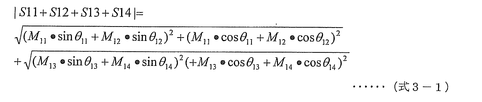
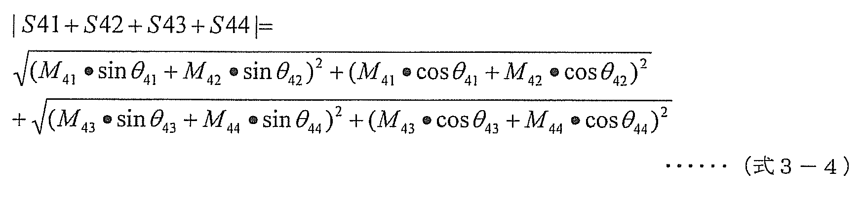
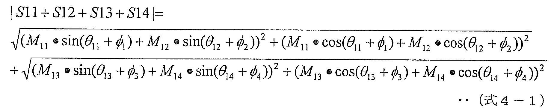
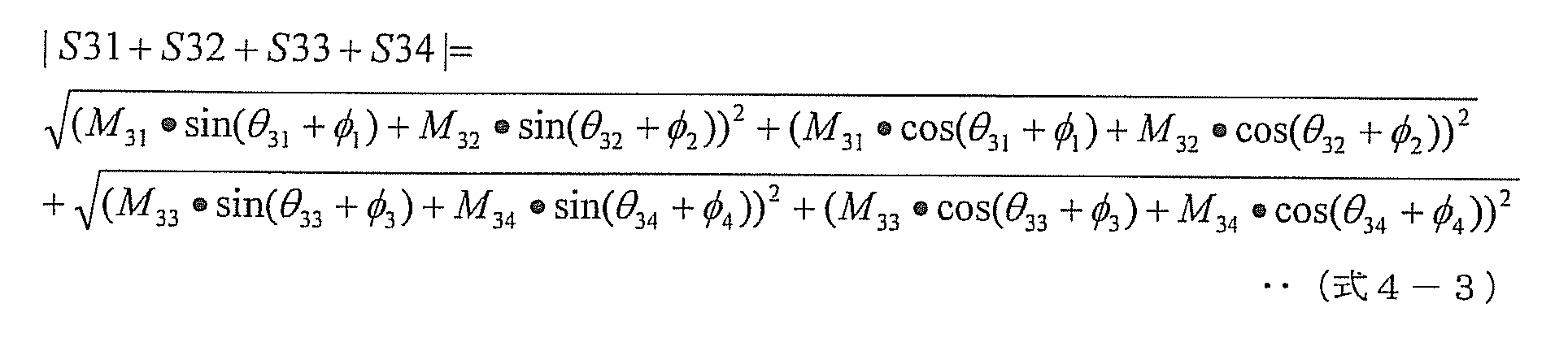
 図17は、本実施形態2に係る高周波加熱装置200の、再サーチ処理の制御手順を示すフローチャートである。
<Re-search process>
FIG. 17 is a flowchart showing the control procedure of the re-search process of the high-frequency heating device 200 according to the second embodiment.
 高周波加熱装置200の制御部210は、加熱処理中に、以下の制御手順により、再サーチ処理を行う。 The control unit 210 of the high-frequency heating device 200 performs a re-search process according to the following control procedure during the heating process.
 同図に示す再サーチ処理は、図12に示した実施形態1における再サーチ処理とほぼ同じであるが、第1の高周波電力発生部220aおよび第2の高周波電力発生部220bに独立に周波数を設定する点が異なる。 The re-search process shown in the figure is almost the same as the re-search process in the first embodiment shown in FIG. 12, but the frequency is independently applied to the first high-frequency power generator 220a and the second high-frequency power generator 220b. The setting is different.
 図17に示すように、制御部210は、まず、現在加熱処理に使用されている周波数および移相量における、各高周波電力ユニット140a,140b,140c,140dにおける反射電力およびスルー電力の振幅と位相とを、図14および図15に示した反射電力検出の制御手順およびスルー電力検出の制御手順により検出し、高周波加熱装置200全体の現在の照射効率を算出する(ステップS2401)。 As shown in FIG. 17, the control unit 210 first determines the amplitude and phase of the reflected power and the through power in each of the high frequency power units 140a, 140b, 140c, and 140d at the frequency and the amount of phase shift currently used in the heat treatment. Are detected by the reflected power detection control procedure and the through power detection control procedure shown in FIGS. 14 and 15, and the current irradiation efficiency of the entire high-frequency heating apparatus 200 is calculated (step S2401).
 次に、それぞれの高周波電力発生部220a,220bの周波数を予め定められた再サーチ用周波数になるように制御して(ステップS2402)、前述した反射電力検出の制御手順により、全ての高周波電力ユニット140a,140b,140c,140dにおける、反射電力の振幅と位相とを検出する(ステップS2403)。 Next, the frequency of each of the high-frequency power generators 220a and 220b is controlled to be a predetermined re-search frequency (step S2402), and all the high-frequency power units are controlled by the reflected power detection control procedure described above. The amplitude and phase of the reflected power at 140a, 140b, 140c, and 140d are detected (step S2403).
 その後、前述したスルー電力検出の制御手順により、全ての高周波電力ユニット140a~140d間におけるスルー電力の振幅および位相を検出する(ステップS2404)。 Thereafter, the amplitude and phase of the through power among all the high-frequency power units 140a to 140d are detected by the above-described control procedure of the through power detection (step S2404).
 次に、再サーチ処理において予め定められている全ての周波数において、反射電力およびスルー電力が検出されたか否かを判定する(ステップS2405)。全ての周波数において反射電力およびスルー電力の振幅および位相が検出されていない場合(ステップS2405でNo)、言い換えると反射電力およびスルー電力の振幅および位相が検出されていない周波数がある場合、以下の処理を行う。制御部210は、それぞれの高周波電力発生部220aおよび220bが発生する高周波電力の周波数を、再サーチ用に予め定められた次の周波数にするように、高周波電力発生部220aおよび220bを制御することにより、次の周波数を設定して(ステップS2406)、上記反射電力の振幅と位相を検出する処理(ステップS2403)及びスルー電力の振幅と位相を検出する処理(ステップS2404)を繰り返す。 Next, it is determined whether or not the reflected power and the through power are detected at all frequencies predetermined in the re-search process (step S2405). When the amplitude and phase of reflected power and through power are not detected at all frequencies (No in step S2405), in other words, when there is a frequency at which the amplitude and phase of reflected power and through power are not detected, the following processing is performed. I do. The control unit 210 controls the high-frequency power generation units 220a and 220b so that the frequency of the high-frequency power generated by each of the high-frequency power generation units 220a and 220b becomes the next frequency predetermined for the re-search. Thus, the next frequency is set (step S2406), and the process of detecting the amplitude and phase of the reflected power (step S2403) and the process of detecting the amplitude and phase of the through power (step S2404) are repeated.
 これを繰り返して、予め定められた全ての再サーチ用の周波数を更新しながら、全ての高周波電力ユニット140a,140b,140c,140dにおける、反射電力およびスルー電力の振幅と位相とを検出する。 This is repeated to detect the amplitude and phase of the reflected power and the through power in all the high- frequency power units 140a, 140b, 140c, and 140d while updating all the predetermined re-search frequencies.
 全ての再サーチ用周波数で、全ての高周波電力ユニット140a,140b,140c,140dにおける、反射電力およびスルー電力の振幅と位相との検出が完了した(ステップS2405でYes)場合、プレ・サーチ処理で説明した通りに、反射電力およびスルー電力の振幅と位相との情報に基づいて、それぞれの高周波電力発生部220a,220bの周波数と各可変移相部142a,142b,142c,142dの移相量を任意の組み合わせに設定し動作させたと仮定したときの照射ロスを計算により推定する(ステップS2407)。なお、この処理(ステップS2407)での処理内容は、図16に示した周波数ごとに各移相量を変化させた場合の照射効率を推定する処理(ステップS2308)と同様である。 When the detection of the amplitude and phase of the reflected power and the through power in all the high- frequency power units 140a, 140b, 140c, and 140d is completed at all re-search frequencies (Yes in step S2405), the pre-search process is performed. As described, based on the information on the amplitude and phase of the reflected power and the through power, the frequency of each high-frequency power generation unit 220a, 220b and the amount of phase shift of each variable phase shift unit 142a, 142b, 142c, 142d are calculated. An irradiation loss when it is assumed that an arbitrary combination is set and operated is estimated by calculation (step S2407). Note that the processing content in this processing (step S2407) is the same as the processing (step S2308) for estimating irradiation efficiency when each phase shift amount is changed for each frequency shown in FIG.
 次に、高周波加熱装置200全体の最良の照射効率の値を算出する(ステップS2408)。 Next, the best irradiation efficiency value of the entire high-frequency heating apparatus 200 is calculated (step S2408).
 そして、再サーチにより算出された最良の照射効率の値(ステップS2408で算出された値)と、先に算出した高周波加熱装置200全体の現在の照射効率の値とをそれぞれ比較する(ステップS2409)。 Then, the best irradiation efficiency value calculated by the re-search (the value calculated in step S2408) is compared with the previously calculated current irradiation efficiency value of the entire high-frequency heating apparatus 200 (step S2409). .
 ここで、再サーチにより算出した最良の照射効率の値が、先に算出した現在の照射効率の値よりも良好な値となる場合は、再サーチにより算出した最良の照射効率となる周波数および移相量にするように、対応する高周波電力発生部220aおよび220bの周波数、および可変移相部142a~142dの移相量をそれぞれ制御する(ステップS2410)。つまり、高周波電力発生部220aおよび220bの周波数、および可変移相部142a~142dの移相量を更新する。一方、先に算出した現在の照射効率の値が、再サーチにより算出した最良の照射効率の値よりも良好な値となる場合は、再サーチを実行する前の元の周波数にするように、対応する高周波電力発生部220aおよび220bの周波数を制御する(ステップS2411)。 If the best irradiation efficiency value calculated by re-searching is better than the current irradiation efficiency value calculated previously, the frequency and shift at which the best irradiation efficiency is calculated by re-searching. The frequencies of the corresponding high-frequency power generation units 220a and 220b and the phase shift amounts of the variable phase shift units 142a to 142d are controlled so as to obtain the phase amount (step S2410). That is, the frequencies of the high-frequency power generators 220a and 220b and the phase shift amounts of the variable phase shifters 142a to 142d are updated. On the other hand, when the value of the current irradiation efficiency calculated earlier is a better value than the value of the best irradiation efficiency calculated by the re-search, so that the original frequency before the re-search is performed, The frequencies of the corresponding high-frequency power generation units 220a and 220b are controlled (step S2411).
 なお、再サーチにより算出した、ある周波数および位相条件における最良の照射効率の値が、現在の照射効率の値よりも良好となる場合であっても、たとえば、1つの高周波電力ユニット140における逆流電力の電力値が、予め定められた閾値を超えてしまう条件であれば、選択する必要はない。つまり、各高周波電力ユニット140における逆流電力の電力値が、予め定められた閾値を超えない条件の中で、最良の照射効率となる条件を選び出してもよい。この閾値は、例えば、半導体素子を含んだ増幅器の故障を防ぐために、増幅器が持つ周波数毎の耐電圧特性によって決めればよい。 Even when the best irradiation efficiency value calculated by re-searching under a certain frequency and phase condition is better than the current irradiation efficiency value, for example, the backflow power in one high-frequency power unit 140 It is not necessary to select the power value if the power value exceeds the predetermined threshold value. That is, a condition that provides the best irradiation efficiency may be selected from the conditions in which the power value of the backflow power in each high-frequency power unit 140 does not exceed a predetermined threshold. This threshold value may be determined by the withstand voltage characteristic for each frequency of the amplifier, for example, in order to prevent failure of the amplifier including the semiconductor element.
 これにより、本実施形態に係る高周波加熱装置200は、加熱処理中に被加熱物の温度や形状が変化することにより最適加熱条件が変化した場合でも、再サーチ処理により常に最適加熱条件の下に加熱できる。 As a result, the high-frequency heating apparatus 200 according to the present embodiment is always under the optimum heating condition by the re-search process even when the optimum heating condition changes due to the temperature and shape of the object to be heated changing during the heating process. Can be heated.
 また、高周波加熱装置200全体の最良の照射効率の値を算出する処理(ステップS2408)において最良の照射効率を算出する際、設定周波数において各高周波電力ユニット140における反射電力およびスルー電力の振幅と位相とを個別に検出した結果を用いて、高周波電力発生部220a,220bの周波数と可変移相部142a,142b,142c,142dの移相量を任意の組み合わせに設定し動作させたと仮定したときの照射ロスを計算し、最も照射効率が良いそれぞれの高周波電力発生部220a,220bの周波数の値と各可変移相部142a,142b,142c,142dの移相量の値を決定することができる。これにより、高周波電力発生部220a,220bの周波数と各可変移相部142a,142b,142c,142dの全ての移相量の組み合わせを実測した場合と比較すると、上述の例の通りに、大幅な時間短縮が図れる。したがって、再サーチ処理を短時間に行うことができ、被加熱物の温度変化等によって再設定が必要な時間を含めた温め時間の延長を短くでき、ユーザの加熱の待ち時間を軽減できる。 Further, when calculating the best irradiation efficiency in the process of calculating the best irradiation efficiency value of the entire high-frequency heating apparatus 200 (step S2408), the amplitude and phase of the reflected power and the through power in each high-frequency power unit 140 at the set frequency. Assuming that the frequency of the high-frequency power generators 220a and 220b and the phase shift amounts of the variable phase shifters 142a, 142b, 142c, and 142d are set to arbitrary combinations and operated. The irradiation loss is calculated, and the value of the frequency of each of the high-frequency power generators 220a and 220b having the best irradiation efficiency and the value of the phase shift amount of each variable phase shifter 142a, 142b, 142c, 142d can be determined. Thereby, compared with the case where the combination of the frequency of the high frequency electric power generation part 220a, 220b and all the phase shift amount of each variable phase shift part 142a, 142b, 142c, 142d is measured, it is large like the above-mentioned example. Time can be shortened. Therefore, the re-search process can be performed in a short time, the extension of the warming time including the time that needs to be reset due to the temperature change of the object to be heated, etc. can be shortened, and the waiting time for heating by the user can be reduced.
 なお、再サーチ処理の開始のタイミングは、前述の実施形態1と同様に、加熱処理中に、常時もしくは定期的に、それぞれの高周波電力ユニット140a,140b,140c,140dから、同相検波信号I(1)~I(4)および直交検波信号Q(1)~Q(4)を取り込んで検出した反射電力の振幅と位相とから算出した電力値と、予め定められた閾値とを比較し、少なくとも1つ以上の高周波電力ユニットにおける逆流電力の電力値が、その閾値を越えた場合に実行してもよい。 Note that the timing of starting the re-search process is the same as that in the first embodiment described above, from the high- frequency power units 140a, 140b, 140c, 140d from the respective high- frequency power units 140a, 140b, 140c, 140d constantly or periodically during the heating process. 1) to I (4) and quadrature detection signals Q (1) to Q (4) are compared with the power value calculated from the amplitude and phase of the reflected power detected and detected, and a predetermined threshold value. You may perform when the electric power value of the backflow power in one or more high frequency electric power units exceeds the threshold value.
 これにより、加熱処理中に被加熱物の温度や形状が変化することにより、反射電力およびスルー電力の大きさが変化した場合でも、予め閾値を定め、これを超えた場合に再サーチ処理を行うことにより、本実施形態に係る高周波加熱装置200は、実施形態1に係る高周波加熱装置100と同様に、常に最適加熱条件の下で被加熱物を加熱できる。 Thus, even when the reflected power and the through power change due to changes in the temperature and shape of the object to be heated during the heat treatment, threshold values are set in advance, and the re-search process is performed when the threshold is exceeded. Accordingly, the high-frequency heating device 200 according to the present embodiment can always heat the object to be heated under the optimum heating condition, similarly to the high-frequency heating device 100 according to the first embodiment.
 なお、前述したプレ・サーチ処理および再サーチ処理を実行する際に、制御部210は、サーチ処理中に過大な反射電力やスルー電力による高周波加熱装置200の故障を防ぐ為に次のようなことしてもよい。特に半導体素子を含んだ増幅器の故障を防ぐ為にの故障を防ぐ為に次のようなことしてもよい。具体的には、それぞれの高周波電力ユニット140a,140b,140c,140dから出力される高周波電力の値を、本加熱の際の高周波電力の値よりも小さい値になるように、それぞれの高周波電力増幅部143a,143b,143c,143dの増幅利得を制御してもよい。 When executing the above-described pre-search process and re-search process, the control unit 210 performs the following to prevent a failure of the high-frequency heating device 200 due to excessive reflected power or through power during the search process. Also good. In particular, the following may be performed in order to prevent failure in order to prevent failure of the amplifier including the semiconductor element. Specifically, each high-frequency power amplification is performed so that the value of the high-frequency power output from each high- frequency power unit 140a, 140b, 140c, 140d is smaller than the value of the high-frequency power at the time of main heating. The amplification gains of the units 143a, 143b, 143c, and 143d may be controlled.
 以上のように、本実施形態に係る高周波加熱装置200は、複数の高周波電力発生部である第1の高周波電力発生部220aおよび第2の高周波電力発生部220bを備える。これにより、実施形態1に係る高周波加熱装置100と比較して、高周波電力ユニット140それぞれにおける反射電力の検出に要する時間を短縮できる。これにより、ユーザが高周波加熱装置200の使用開始ボタンを押して実際に本加熱処理を行う前に、より短時間に最適な周波数の組み合わせ、および、移相量の組み合わせを決定することができ、ユーザの利便性を向上させる。 As described above, the high-frequency heating apparatus 200 according to the present embodiment includes the first high-frequency power generation unit 220a and the second high-frequency power generation unit 220b, which are a plurality of high-frequency power generation units. Thereby, compared with the high frequency heating apparatus 100 which concerns on Embodiment 1, the time which the detection of the reflected electric power in each high frequency electric power unit 140 can be shortened. Thereby, before the user presses the use start button of the high-frequency heating device 200 and actually performs the main heating process, the optimum frequency combination and phase shift amount combination can be determined in a shorter time. Improve the convenience.
 また、実施形態1に係る高周波加熱装置100と比較して、2つの高周波電力発生部である第1の高周波電力発生部220aおよび第2の高周波電力発生部220bを有し、それらが発生する高周波電力の周波数を互いに独立とできる。よって、高周波加熱装置200は、加熱室へ放射する複数の高周波電力の周波数における自由度が高くなるので、最大照射効率が向上する。 Further, compared with the high-frequency heating device 100 according to the first embodiment, the first high-frequency power generation unit 220a and the second high-frequency power generation unit 220b, which are two high-frequency power generation units, have high frequencies generated by them. The frequency of power can be made independent of each other. Therefore, since the high frequency heating apparatus 200 has a high degree of freedom in the frequency of the plurality of high frequency powers radiated to the heating chamber, the maximum irradiation efficiency is improved.
 (実施形態3)
 本実施形態に係る高周波加熱装置は、実施形態2に係る高周波加熱装置200が2つの高周波電力発生部を有しているのに対し、高周波加熱装置が4つの高周波電力ユニット各々に高周波電力を供給する4つの高周波電力発生部を有している点が異なる。この構成により、全ての高周波電力ユニットから発生される高周波の周波数を個別に制御することができるため、最大照射効率を更に高めることができる。以下、実施形態2との相違点を中心に、本発明の実施形態3を、図面を参照しながら説明する。なお、本実施形態3の説明において、前述の実施形態1および実施形態2と同じ機能を有する構成要素には同じ参照符号を付し、説明を省略する。また、前述の実施形態1および実施形態2と同じ作用を有する内容についても、説明を省略する。
(Embodiment 3)
In the high-frequency heating device according to the present embodiment, the high-frequency heating device 200 according to the second embodiment has two high-frequency power generation units, whereas the high-frequency heating device supplies high-frequency power to each of the four high-frequency power units. The difference is that it has four high-frequency power generators. With this configuration, since the high frequency generated from all the high frequency power units can be individually controlled, the maximum irradiation efficiency can be further increased. Hereinafter, a third embodiment of the present invention will be described with reference to the drawings, centering on differences from the second embodiment. In the description of the third embodiment, components having the same functions as those of the first embodiment and the second embodiment described above are denoted by the same reference numerals, and the description thereof is omitted. Also, the description of the contents having the same functions as those of the first and second embodiments is omitted.
 図18は、本発明の実施形態3における、高周波加熱装置の構成を示すブロック図である。 FIG. 18 is a block diagram showing a configuration of a high-frequency heating device in Embodiment 3 of the present invention.
 同図に示す高周波加熱装置300は、図13に示した高周波加熱装置200と比較して、第1の高周波電力発生部220aおよび第2の高周波電力発生部220bに代わり、第1の高周波電力発生部320aと、第2の高周波電力発生部320bと、第3の高周波電力発生部320cと、第4の高周波電力発生部320dとを備え、制御部210に代わり、制御部310を備えている。それぞれの高周波電力ユニット140a,140b,140c,140dの構成は、前述の実施形態1および2と同じであるので、説明は省略する。なお、第1~第4の高周波電力発生部320a~320dを、高周波電力発生部320a~320dと記載する場合がある。 The high-frequency heating device 300 shown in the figure is different from the high-frequency heating device 200 shown in FIG. 13 in that the first high-frequency power generation unit 220a and the second high-frequency power generation unit 220b are replaced with the first high-frequency power generation unit 220b. Unit 320 a, second high-frequency power generation unit 320 b, third high-frequency power generation unit 320 c, and fourth high-frequency power generation unit 320 d, and includes control unit 310 instead of control unit 210. Since the configuration of each of the high- frequency power units 140a, 140b, 140c, and 140d is the same as that of the first and second embodiments, description thereof will be omitted. The first to fourth high-frequency power generation units 320a to 320d may be referred to as high-frequency power generation units 320a to 320d.
 第1の高周波電力発生部320aで発生された高周波電力は、第1の高周波電力ユニット140aへ、第2の高周波電力発生部320bで発生された高周波電力は、第2の高周波電力ユニット140bへ、第3の高周波電力発生部320cで発生された高周波電力は、第3の高周波電力ユニット140cへ、第4の高周波電力発生部320dで発生された高周波電力は、第4の高周波電力ユニット140dへ、それぞれ入力される。それぞれの高周波電力発生部320a,320b,320c,320dから、それぞれの高周波電力ユニット140a,140b,140c,140dへ入力された高周波電力は、それぞれ、分配部141a,141b,141c,141dを介して、可変移相部142a,142b,142c,142dへ入力される。可変移相部142a,142b,142c,142dへ入力された高周波電力は移相処理を施され、高周波電力増幅部143a,143b,143c,143dへ入力される。高周波電力増幅部143a,143b,143c,143dに入力された高周波電力は、対象物の加熱処理に適した電力に増幅され、方向性結合部144a,144b,144c,144dを介して、放射部150a,150b,150c,150dより対象物に照射される。 The high-frequency power generated by the first high-frequency power generator 320a is sent to the first high-frequency power unit 140a, and the high-frequency power generated by the second high-frequency power generator 320b is sent to the second high-frequency power unit 140b. The high frequency power generated by the third high frequency power generation unit 320c is transferred to the third high frequency power unit 140c, and the high frequency power generated by the fourth high frequency power generation unit 320d is transferred to the fourth high frequency power unit 140d. Each is entered. The high-frequency power input from the high- frequency power generators 320a, 320b, 320c, and 320d to the high- frequency power units 140a, 140b, 140c, and 140d is respectively distributed through the distributors 141a, 141b, 141c, and 141d. Input to the variable phase shifters 142a, 142b, 142c, 142d. The high frequency power input to the variable phase shifters 142a, 142b, 142c, 142d is subjected to phase shift processing and input to the high frequency power amplifiers 143a, 143b, 143c, 143d. The high-frequency power input to the high- frequency power amplifiers 143a, 143b, 143c, and 143d is amplified to power suitable for the heat treatment of the object, and the radiation unit 150a is passed through the directional coupling units 144a, 144b, 144c, and 144d. , 150b, 150c, 150d, the object is irradiated.
 制御部310は、図13に示した制御部210と比較して、高周波電力増幅部143a~143dへ、それぞれ、周波数制御信号Cfreq1~Cfreq4を出力する。具体的には、制御部310は、高周波電力発生部320a,320b,320c,320d、可変移相部142a,142b,142c,142d、および高周波電力増幅部143a,143b,143c,143dにそれぞれ接続されており、各々の高周波電力発生部320a,320b,320c,320dにそれぞれの周波数制御信号Cfreq1、Cfreq2、Cfreq3、Cfreq4を出力する。 The control unit 310 outputs frequency control signals Cfreq1 to Cfreq4 to the high frequency power amplification units 143a to 143d, respectively, as compared with the control unit 210 shown in FIG. Specifically, the control unit 310 is connected to the high frequency power generation units 320a, 320b, 320c, and 320d, the variable phase shift units 142a, 142b, 142c, and 142d, and the high frequency power amplification units 143a, 143b, 143c, and 143d, respectively. The frequency control signals Cfreq1, Cfreq2, Cfreq3, and Cfreq4 are output to the high frequency power generators 320a, 320b, 320c, and 320d, respectively.
 それぞれの高周波電力発生部320a,320b,320c,320dは、制御部310から入力された個別の周波数制御信号Cfreq1、Cfreq2、Cfreq3、Cfreq4に応じてそれぞれの周波数を変化させる。 Each of the high- frequency power generators 320a, 320b, 320c, and 320d changes the frequency according to the individual frequency control signals Cfreq1, Cfreq2, Cfreq3, and Cfreq4 input from the controller 310.
 図18の高周波加熱装置300の基本的な制御手順は、前述の実施形態1で説明した図4に示した、図1の高周波加熱装置100の基本的な制御手順を示すフローチャートと同様である。 The basic control procedure of the high-frequency heating device 300 in FIG. 18 is the same as the flowchart showing the basic control procedure of the high-frequency heating device 100 in FIG. 1 shown in FIG. 4 described in the first embodiment.
 ただし、前述の図1で説明した高周波加熱装置100は、全ての高周波電力ユニット140a,140b,140c,140dは同じ周波数で動作するのに対して、本実施形態の図18に示す高周波加熱装置300においては、第1の高周波電力ユニット140aは、第1の高周波電力発生部320aの周波数で動作し、第2の高周波電力ユニット140bは、第2の高周波電力発生部320bの周波数で動作し、第3の高周波電力ユニット140cは、第3の高周波電力発生部320cの周波数で動作し、第4の高周波電力ユニット140dは、第4の高周波電力発生部320dの周波数で、それぞれ動作する。 However, in the high-frequency heating device 100 described with reference to FIG. 1, all the high- frequency power units 140a, 140b, 140c, and 140d operate at the same frequency, whereas the high-frequency heating device 300 shown in FIG. 18 of the present embodiment. The first high-frequency power unit 140a operates at the frequency of the first high-frequency power generation unit 320a, the second high-frequency power unit 140b operates at the frequency of the second high-frequency power generation unit 320b, The third high frequency power unit 140c operates at the frequency of the third high frequency power generation unit 320c, and the fourth high frequency power unit 140d operates at the frequency of the fourth high frequency power generation unit 320d.
 上述の高周波加熱装置300の構成によれば、それぞれの高周波電力発生部320a,320b,320c,320dの周波数を実際に変化させて高周波電力を放射させた場合に、直交検波部145a、145b、145c、145dにおいて検出された同相検波信号I(1)~I(4)と、直交検波信号Q(1)~Q(4)とから、高周波電力発生部320a,320b,320c,320dのそれぞれにおける周波数毎の、反射による逆流電力の振幅および位相と通り抜けによる逆流電力の振幅および位相を検出する(求める)ことができる。 According to the configuration of the above-described high-frequency heating device 300, when the high-frequency power is radiated by actually changing the frequency of each of the high-frequency power generation units 320a, 320b, 320c, and 320d, the quadrature detection units 145a, 145b, and 145c are used. From the in-phase detection signals I (1) to I (4) detected at 145d and the quadrature detection signals Q (1) to Q (4), the frequency at each of the high-frequency power generation units 320a, 320b, 320c, and 320d The amplitude and phase of the backflow power due to reflection and the amplitude and phase of the backflow power due to passing through can be detected (determined).
 この得られた周波数毎の反射による逆流電力の振幅と位相および通り抜けによる逆流電力の振幅と位相の値を用いて、それぞれの高周波電力発生部320a,320b,320c,320dの周波数と、各々の可変移相部142a,142b,142c,142dの移相量を任意の組み合わせに設定し動作させたと仮定したときの照射ロスを計算する。そして、計算結果から最も高周波加熱装置300全体の照射効率が良いそれぞれの高周波電力発生部320a,320b,320c,320dの周波数の組み合わせと、各々の可変移相部142a,142b,142c,142dの移相量の組み合わせとを決定することができる。すなわち、それぞれの高周波電力発生部320a,320b,320c,320dの周波数と、各々の可変移相部142a,142b,142c,142dの移相量のすべての組み合わせにおいて実際に測定することなく、最低限の実測値から最適な照射効率を計算で求めることができる。よって、時間がかかる実測を少なくすることができる。これにより、ユーザが高周波加熱装置の加熱をスタートしてから実際に加熱が始まる前までの高効率の照射を見つけるための準備時間を短くすることができる。 Using the obtained amplitude and phase of the backflow power due to reflection at each frequency and the value of the backflow power amplitude and phase due to passing through, the frequency of each of the high- frequency power generators 320a, 320b, 320c, and 320d and the respective variable An irradiation loss is calculated when it is assumed that the phase shift amounts of the phase shift units 142a, 142b, 142c, and 142d are set to an arbitrary combination and operated. Then, from the calculation results, the combination of the frequencies of the high- frequency power generators 320a, 320b, 320c, and 320d with the best irradiation efficiency of the entire high-frequency heating device 300 and the shifts of the variable phase shifters 142a, 142b, 142c, and 142d are obtained. A combination of phase amounts can be determined. That is, without actually measuring in all combinations of the frequencies of the respective high- frequency power generators 320a, 320b, 320c, and 320d and the phase shift amounts of the variable phase shifters 142a, 142b, 142c, and 142d, the minimum The optimum irradiation efficiency can be obtained by calculation from the actually measured values. Therefore, time-consuming actual measurement can be reduced. Thereby, it is possible to shorten the preparation time for finding high-efficiency irradiation from when the user starts heating the high-frequency heating device to before the heating actually starts.
 高周波電力発生部320a,320b,320c,320dの具体的な構成は、前述した実施形態1で説明した、図2に示す高周波電力発生部120の具体的な構成と同一であるので、説明は省略する。 The specific configuration of the high-frequency power generation units 320a, 320b, 320c, and 320d is the same as the specific configuration of the high-frequency power generation unit 120 shown in FIG. To do.
 なお、図18において、高周波加熱装置300は、4つの高周波電力発生部と4つの高周波電力ユニット140で構成されているが、高周波電力発生部の数と高周波電力ユニット140の数が同数であればよく、その数量に限定されるものではない。 In FIG. 18, the high-frequency heating device 300 includes four high-frequency power generation units and four high-frequency power units 140, but the number of high-frequency power generation units and the number of high-frequency power units 140 are the same. Well, it is not limited to that quantity.
 <反射電力の検出方法>
 図19は、本実施形態3に係る高周波加熱装置300の反射電力検出の制御手順を示すフローチャートである。
<Detection method of reflected power>
FIG. 19 is a flowchart showing a control procedure for detecting reflected power of the high-frequency heating apparatus 300 according to the third embodiment.
 高周波加熱装置300の制御部310は、以下の制御手順により、それぞれの高周波電力ユニット140a,140b,140c,140dの反射電力の検出を行う。 The control unit 310 of the high-frequency heating device 300 detects the reflected power of each of the high- frequency power units 140a, 140b, 140c, and 140d according to the following control procedure.
 同図に示す反射電力検出方法は、それぞれの高周波電力発生部320a,320b,320c,320dが、全て異なる周波数で動作している場合と、2個以上の高周波電力発生部が同一の周波数で動作している場合とで異なる。 In the reflected power detection method shown in the figure, when the high- frequency power generators 320a, 320b, 320c, and 320d are all operating at different frequencies, two or more high-frequency power generators operate at the same frequency. It differs depending on the case.
 まず、第1~第4の高周波電力発生部320a~320dで、発生されている高周波電力の周波数が互いに異なるか否かを判定する(ステップS3101)。 First, the first to fourth high-frequency power generators 320a to 320d determine whether or not the frequencies of the generated high-frequency power are different from each other (step S3101).
 それぞれの高周波電力発生部320a,320b,320c,320dが全て異なる周波数で動作している場合(ステップS3101でYes)は、制御部310は、それぞれの高周波電力ユニット140a,140b,140c,140dからの、同相検波信号I(1)~I(4)および直交検波信号Q(1)~Q(4)を取り込み、それぞれの高周波電力ユニット140a,140b,140c,140dにおける逆流電力の振幅と位相とを検出する(ステップS3102)。この処理は、各高周波電力ユニット140間において、並行して実施できる。これにより、それぞれの高周波電力ユニット140a,140b,140c,140dの反射電力を短時間で検出できる。 When each of the high-frequency power generation units 320a, 320b, 320c, and 320d is operating at a different frequency (Yes in step S3101), the control unit 310 receives from each of the high- frequency power units 140a, 140b, 140c, and 140d. In-phase detection signals I (1) to I (4) and quadrature detection signals Q (1) to Q (4) are taken in, and the amplitude and phase of the backflow power in each of the high- frequency power units 140a, 140b, 140c, and 140d are obtained. Detection is performed (step S3102). This process can be performed in parallel between the high-frequency power units 140. Thereby, the reflected power of each high frequency power unit 140a, 140b, 140c, 140d can be detected in a short time.
 一方、2個以上の高周波電力発生部が同一の周波数で動作している場合(ステップS3101でNo、例えば、第1の高周波電力発生部320aが周波数Aで動作し、第2および第3の高周波電力発生部320b,320cが周波数Bで動作し、第4の高周波電力発生部320dが周波数Cで動作している場合)は、他の高周波電力ユニット140と周波数が重複するか否かを判定する(ステップS3103)。 On the other hand, when two or more high-frequency power generation units are operating at the same frequency (No in step S3101, for example, the first high-frequency power generation unit 320a operates at frequency A, and the second and third high-frequency power generation units When the power generation units 320b and 320c operate at the frequency B and the fourth high frequency power generation unit 320d operates at the frequency C), it is determined whether or not the frequency overlaps with the other high frequency power units 140. (Step S3103).
 制御部310は、他の高周波電力ユニット140と周波数が重複しない高周波電力ユニット(ステップS3103でNo、例えば、第1および第4の高周波電力ユニット140a,140d)については、重複しない高周波電力ユニット140の同相検波信号および直交検波信号を取り込み、重複しない高周波電力ユニット140の逆流電力の振幅と位相とを検出する(ステップS3104)。この処理は、他の高周波電力ユニット140と周波数が重複しない高周波電力ユニット140間において、並行して実施できる。これにより、他の高周波電力ユニット140と周波数が重複しない高周波電力ユニット140の反射電力を短時間で検出できる。 The control unit 310 determines the high-frequency power unit 140 that does not overlap with other high-frequency power units 140 (No in step S3103, for example, the first and fourth high- frequency power units 140a and 140d). The in-phase detection signal and the quadrature detection signal are captured, and the amplitude and phase of the backflow power of the high-frequency power unit 140 that do not overlap are detected (step S3104). This process can be performed in parallel between the high-frequency power units 140 whose frequencies do not overlap with those of the other high-frequency power units 140. Thereby, the reflected power of the high frequency power unit 140 whose frequency does not overlap with other high frequency power units 140 can be detected in a short time.
 一方、他の高周波電力ユニット140と周波数が重複する高周波電力ユニット140(ステップS3103でYes、例えば、第2および第3の高周波電力ユニット140b,140c)について(ステップS3103でYesの場合)は、制御部310は、1つの高周波電力ユニット140(例えば、第2の高周波電力ユニット140b)以外の高周波電力ユニット140(例えば、第3の高周波電力ユニット140c)の出力電力が、当該1つの高周波電力ユニット140の反射電力の検出に影響を与えないレベルになるよう制御する(ステップS3105)。当該1つの高周波電力ユニット140以外の高周波電力ユニット140の、高周波電力増幅部の増幅利得を制御した後、制御部310は、反射電力を検出しようとする当該1つの高周波電力ユニット140の同相検波信号および直交検波信号を取り込み、当該1つの高周波電力ユニット140の逆流電力の振幅と位相とを検出する(ステップS3106)。 On the other hand, the high frequency power unit 140 whose frequency overlaps with the other high frequency power units 140 (Yes in step S3103, for example, the second and third high frequency power units 140b and 140c) (in the case of Yes in step S3103) is controlled. The unit 310 is configured such that the output power of a high-frequency power unit 140 (for example, the third high-frequency power unit 140c) other than one high-frequency power unit 140 (for example, the second high-frequency power unit 140b) is the single high-frequency power unit 140. The level is controlled so as not to affect the detection of the reflected power (step S3105). After controlling the amplification gain of the high-frequency power amplification unit of the high-frequency power unit 140 other than the one high-frequency power unit 140, the control unit 310 detects the common-mode detection signal of the one high-frequency power unit 140 that attempts to detect the reflected power. Then, the quadrature detection signal is taken in, and the amplitude and phase of the backflow power of the one high frequency power unit 140 are detected (step S3106).
 次に、全ての高周波電力ユニット140において、上記処理が完了したか否かを判定し(ステップS3107)、完了していない場合(ステップS3107でNo)、別の高周波電力ユニット140を検出対象として(ステップS3108)上記の検出対象とした1つの高周波電力ユニット140以外の高周波電力ユニット140の出力電圧を下げる処理(ステップS3105)および当該検出対象とした高周波電力ユニット140における逆流電力の振幅と位相を検出する処理(ステップS3106)を繰り返す。 Next, it is determined whether or not the above processing is completed in all the high-frequency power units 140 (step S3107). If not completed (No in step S3107), another high-frequency power unit 140 is detected ( Step S3108) Processing for lowering the output voltage of the high-frequency power unit 140 other than the one high-frequency power unit 140 as the detection target (step S3105), and detecting the amplitude and phase of the backflow power in the high-frequency power unit 140 as the detection target This process (step S3106) is repeated.
 一方、全ての高周波電力ユニット140において、上記処理が完了している場合(ステップS3107でYes)、処理を終了する。これにより、他の高周波電力ユニット140と周波数が重複する高周波電力ユニット140の反射電力を検出できる。 On the other hand, when the above process is completed in all the high-frequency power units 140 (Yes in step S3107), the process ends. Thereby, the reflected power of the high frequency power unit 140 whose frequency overlaps with that of the other high frequency power unit 140 can be detected.
 以上のように、他の高周波電力ユニット140と周波数が重複しない高周波電力ユニット140に関しては、同時に反射電力を検出できるので、短時間に反射電力の検出が可能となる。本実施形態に係る高周波加熱装置300は、各高周波電力ユニット140に対応して、周波数を独立に設定できるので、実施形態2に係る高周波加熱装置200と比較して、より短時間に反射電力の振幅および位相を検出できる。 As described above, since the reflected power can be detected at the same time with respect to the high frequency power unit 140 whose frequency does not overlap with that of the other high frequency power units 140, the reflected power can be detected in a short time. Since the high-frequency heating device 300 according to the present embodiment can set the frequency independently corresponding to each high-frequency power unit 140, the reflected power can be reduced in a shorter time than the high-frequency heating device 200 according to the second embodiment. Amplitude and phase can be detected.
 <スルー電力の検出方法>
 図20は、本実施形態3に係る高周波加熱装置300のスルー電力検出の第1の制御手順を示すフローチャートである。
<Through power detection method>
FIG. 20 is a flowchart illustrating a first control procedure of through power detection of the high-frequency heating device 300 according to the third embodiment.
 高周波加熱装置300の制御部310は、以下の制御手順により、それぞれの高周波電力ユニット140a,140b,140c,140d間相互のスルー電力の検出を行う。 The control unit 310 of the high-frequency heating device 300 detects through power between the high- frequency power units 140a, 140b, 140c, and 140d according to the following control procedure.
 同図に示すように、制御部310は、まず、任意の1つの高周波電力ユニット140(例えば、周波数Aで動作している、第1の高周波電力ユニット140a)のみ高周波電力を出力し、他の高周波電力ユニット140(例えば、任意の周波数で動作している、第2,第3,第4の高周波電力ユニット140b,140c,140d)の出力電力を、各高周波電力ユニット140における反射電力の検出レベルが充分に小さくなるように、それぞれの高周波電力ユニット140の高周波電力増幅部の増幅利得を制御する(ステップS3201)。 As shown in the figure, the control unit 310 first outputs high-frequency power only to any one high-frequency power unit 140 (for example, the first high-frequency power unit 140a operating at the frequency A), and the other The output power of the high-frequency power unit 140 (for example, the second, third, and fourth high- frequency power units 140b, 140c, and 140d operating at an arbitrary frequency) is used as the detection level of reflected power in each high-frequency power unit 140. Is controlled so that the amplification gain of the high-frequency power amplification unit of each high-frequency power unit 140 is sufficiently small (step S3201).
 次に、制御部310は、高周波電力の出力レベルを小さくするように制御した、他の高周波電力ユニット140(例えば、第2,第3,第4の高周波電力ユニット140b,140c,140d)に高周波電力をそれぞれ供給している、高周波電力発生部(例えば、第2,第3,第4の高周波電力発生部320b,320c,320d)の周波数を、高周波電力が出力されている1つの高周波電力ユニット140(例えば、第1の高周波電力ユニット140a)に高周波電力を供給している、高周波電力発生部(例えば、第1の高周波電力発生部320a)と同じ周波数(例えば、周波数A)にするように、それぞれの高周波電力発生部(例えば、第2,第3,第4の高周波電力発生部320b,320c,320d)の周波数を制御する(ステップS3202)。 Next, the control unit 310 controls the other high-frequency power units 140 (for example, the second, third, and fourth high- frequency power units 140b, 140c, and 140d) that are controlled to reduce the output level of the high-frequency power. One high-frequency power unit that outputs the high-frequency power as the frequency of each of the high-frequency power generation units (for example, the second, third, and fourth high-frequency power generation units 320b, 320c, and 320d) that supplies power. 140 (for example, the first high-frequency power unit 140a) is supplied with high-frequency power so as to have the same frequency (for example, frequency A) as the high-frequency power generation unit (for example, the first high-frequency power generation unit 320a). , Control the frequency of each high-frequency power generator (for example, the second, third, and fourth high- frequency power generators 320b, 320c, and 320d) Step S3202).
 制御部310は、他のそれぞれの高周波電力ユニット140(例えば、第2,第3,第4の高周波電力ユニット140b,140c,140d)の同相検波信号および直交検波信号を取り込み、高周波電力が出力されている1つの高周波電力ユニット140(例えば、第1の高周波電力ユニット140a)から、他のそれぞれの高周波電力ユニット140(例えば、第2,第3,第4の高周波電力ユニット140b,140c,140d)へのスルー電力(例えば、第1の高周波電力ユニット140aから第2の高周波電力ユニット140bへのスルー電力、第1の高周波電力ユニット140aから第3の高周波電力ユニット140cへのスルー電力、および第1の高周波電力ユニット140aから第4の高周波電力ユニット140dへのスルー電力)の振幅と位相とを検出する(ステップS3203)。 The control unit 310 captures the in-phase detection signal and the quadrature detection signal of each of the other high-frequency power units 140 (for example, the second, third, and fourth high- frequency power units 140b, 140c, and 140d), and the high-frequency power is output. One high frequency power unit 140 (for example, the first high frequency power unit 140a) to the other high frequency power unit 140 (for example, the second, third, and fourth high frequency power units 140b, 140c, and 140d). Through power (eg, through power from the first high-frequency power unit 140a to the second high-frequency power unit 140b, through power from the first high-frequency power unit 140a to the third high-frequency power unit 140c, and the first From the high frequency power unit 140a to the fourth high frequency power unit 140d Detecting the amplitude and phase of Lou power) (step S3203).
 次に、全ての高周波電力ユニット140からのスルー電力の検出が完了したか否かを判定し(ステップS3204)、完了していない場合(ステップS3204でNo)、別の高周波電力ユニット140を検出対象として(ステップS3205)、上記の検出対象とした1つの高周波電力ユニット140以外の高周波電力ユニット140の出力電圧を下げる処理(ステップS3202)から他の高周波電力ユニット140において逆流電力の振幅と位相を検出する処理(ステップS3203)までを繰り返す。 Next, it is determined whether or not the detection of through power from all the high-frequency power units 140 has been completed (step S3204). If not completed (No in step S3204), another high-frequency power unit 140 is detected. (Step S3205) From the process of reducing the output voltage of the high-frequency power unit 140 other than the one high-frequency power unit 140 as the detection target (step S3202), the amplitude and phase of the backflow power are detected in the other high-frequency power units 140. The process up to (step S3203) is repeated.
 一方、全ての高周波電力ユニット140からのスルー電力の検出が完了した場合(ステップS3204でYes)、このスルー電力検出処理を終了する。 On the other hand, when the detection of the through power from all the high-frequency power units 140 is completed (Yes in step S3204), the through power detection process is terminated.
 これにより、全ての高周波電力ユニット140間における相互のスルー電力の振幅と位相とを検出する。 Thereby, the amplitude and phase of the mutual through power between all the high-frequency power units 140 are detected.
 なお、スルー電力の検出は以下のように実施してもよい。 Note that detection of through power may be performed as follows.
 図21は、本実施形態による高周波加熱装置300の、スルー電力検出の第2の制御手順を示すフローチャートである。 FIG. 21 is a flowchart showing a second control procedure of through power detection of the high-frequency heating device 300 according to the present embodiment.
 同図に示すように、制御部310は、まず、任意の1つの高周波電力ユニット140(例えば、周波数Aで動作している、第1の高周波電力ユニット140a)のみ出力電力を、その高周波電力ユニット140における反射電力の検出レベルが充分に小さくなるように、高周波電力増幅部の増幅利得を制御する(ステップS3301)。 As shown in the figure, the control unit 310 first outputs output power from only one arbitrary high-frequency power unit 140 (for example, the first high-frequency power unit 140a operating at the frequency A). The amplification gain of the high-frequency power amplification unit is controlled so that the detection level of the reflected power at 140 is sufficiently small (step S3301).
 次に制御部310は、出力電力が小さくなるように制御した1つの高周波電力ユニット140(例えば、第1の高周波電力ユニット140a)に高周波電力を供給している高周波電力発生部(例えば、第1の高周波電力発生部320a)の周波数を、他の高周波電力ユニット(例えば、周波数Bで動作している第2の高周波電力ユニット140b、周波数Cで動作している第3の高周波電力ユニット140c、および周波数Dで動作している第4の高周波電力ユニット140d)の内のいずれか1つの高周波電力ユニット(例えば、第2の高周波電力ユニット140b)に高周波電力を供給している、高周波電力発生部(例えば、第2の高周波電力発生部320b)が動作している周波数(例えば、周波数B)と同じ周波数になるように制御する(ステップS3302)。 Next, the control unit 310 supplies a high-frequency power to one high-frequency power unit 140 (for example, the first high-frequency power unit 140a) that is controlled so that the output power is reduced (for example, the first high-frequency power generation unit (for example, the first high-frequency power unit 140a)). The frequency of the high-frequency power generation unit 320a) is changed to another high-frequency power unit (for example, the second high-frequency power unit 140b operating at the frequency B, the third high-frequency power unit 140c operating at the frequency C, and A high-frequency power generation unit (which supplies high-frequency power to any one high-frequency power unit (for example, the second high-frequency power unit 140b) among the fourth high-frequency power units 140d) operating at the frequency D ( For example, the second high frequency power generation unit 320b) is controlled so as to have the same frequency as the frequency at which the second high frequency power generation unit 320b is operating (for example, frequency B). (Step S3302).
 次に制御部310は、出力電力が小さくなるように制御した1つの高周波電力ユニット140(例えば、第1の高周波電力ユニット140a)の同相検波信号および直交検波信号を取り込み、同じ周波数で動作している他の1つの高周波電力ユニット140(例えば、第2の高周波電力ユニット140b)から、出力電力が小さくなるように制御した1つの高周波電力ユニット140(例えば、第1の高周波電力ユニット140a)への逆流電力の振幅と位相とを検出する(ステップS3303)。 Next, the control unit 310 takes in the in-phase detection signal and the quadrature detection signal of one high-frequency power unit 140 (for example, the first high-frequency power unit 140a) controlled so as to reduce the output power, and operates at the same frequency. One other high-frequency power unit 140 (for example, the second high-frequency power unit 140b) to one high-frequency power unit 140 (for example, the first high-frequency power unit 140a) that is controlled so as to reduce the output power. The amplitude and phase of the backflow power are detected (step S3303).
 そして、他のすべての高周波電力ユニット140から出力電力が小さくなるように制御した1つの高周波電力ユニット140への逆流電力の振幅と位相とを検出したか否kを判定する(ステップS3304)。 Then, it is determined whether or not the amplitude and phase of the backflow power to one high-frequency power unit 140 controlled so that the output power is reduced from all other high-frequency power units 140 is detected (step S3304).
 完了していない場合(ステップS3304でNo)、出力電力が小さくなるように制御した1つの高周波電力ユニット140に対応する周波数を、他の1つの高周波電力ユニット140に対応する周波数(例えば、周波数C)に設定し(ステップS3305)、以下の処理を繰り返す。つまり、上記の出力電力が小さくなるように制御した1つの高周波電力ユニット140に対応する周波数を他の1つの高周波電力ユニット140に対応する周波数に設定する処理(ステップS3302)および逆流電力の振幅と位相を検出する処理(ステップS3303)を繰り返す。 If not completed (No in step S3304), the frequency corresponding to one high-frequency power unit 140 controlled to reduce the output power is changed to the frequency corresponding to the other one high-frequency power unit 140 (for example, frequency C ) (Step S3305), and the following processing is repeated. That is, the process (step S3302) of setting the frequency corresponding to one high frequency power unit 140 controlled to reduce the output power to the frequency corresponding to the other high frequency power unit 140, and the amplitude of the backflow power The process of detecting the phase (step S3303) is repeated.
 これにより、他の全ての高周波電力ユニット140(例えば、第2~第4の高周波電力ユニット140b~140d)から、出力電力が小さくなるように制御した1つの高周波電力ユニット140(例えば、第1の高周波電力ユニット140a)へのスルー電力の振幅と位相とを検出する(ステップS3304でYes)。 As a result, one high-frequency power unit 140 (for example, the first high-frequency power unit 140 (for example, the first high-frequency power unit 140b to 140d) is controlled so that the output power is reduced. The amplitude and phase of the through power to the high frequency power unit 140a) are detected (Yes in step S3304).
 次に、制御部310は、全ての高周波電力ユニット140においてスルー電力の検出が完了したか否かを判定し(ステップS3306)、完了していない場合(ステップS3306でNo)、次の任意の1つの高周波電力ユニット140(例えば、周波数Bで動作している、第2の高周波電力ユニット140b)を検出対象とする(ステップS3307)。 Next, the control unit 310 determines whether or not detection of through power has been completed in all the high-frequency power units 140 (step S3306), and if not completed (No in step S3306), the next arbitrary 1 Two high-frequency power units 140 (for example, the second high-frequency power unit 140b operating at the frequency B) are set as detection targets (step S3307).
 そして、新たに検出対象とした1つの高周波電力ユニット140の出力電力を下げる処理(ステップS3301)以降の処理を繰り返す。 And the process after the process (step S3301) of lowering the output power of one high frequency power unit 140 newly set as a detection target is repeated.
 一方、全ての高周波電力ユニット140において、スルー電力の検出が完了した場合(ステップS3306でYes)、このスルー電力検出処理を完了する。 On the other hand, when the detection of through power is completed in all the high-frequency power units 140 (Yes in step S3306), this through power detection process is completed.
 これにより、全ての高周波電力ユニット140間の相互スルー電力の振幅と位相とを検出できる。 Thereby, the amplitude and phase of the mutual through power between all the high-frequency power units 140 can be detected.
 <プレ・サーチ処理>
 本実施形態3による本加熱前における最適加熱条件の決定処理(プレ・サーチ処理)は実施形態2で示した図16と同様の制御手順で行う。
<Pre-search process>
The optimum heating condition determination process (pre-search process) before the main heating according to the third embodiment is performed by the same control procedure as that of FIG.
 プレ・サーチ用に予め定められた全ての周波数において、全ての高周波電力ユニット140a,140b,140c,140dにおける反射電力の振幅と位相、および全ての高周波電力ユニット140a,140b,140c,140d間における相互のスルー電力の振幅と位相との検出が完了することによって、前述の実施形態1および実施形態2と同様に、各周波数での、各高周波電力発生ユニットの反射電力特性、および各高周波電力発生ユニット間に於ける相互のスルー電力特性を、振幅と位相を用いて表現する、図8に示すようなマトリクスが得られる。 The amplitude and phase of the reflected power in all the high- frequency power units 140a, 140b, 140c, 140d, and the mutual relationship between all the high- frequency power units 140a, 140b, 140c, 140d at all the frequencies predetermined for the pre-search. By completing the detection of the amplitude and phase of the through power, the reflected power characteristics of each high-frequency power generation unit and each high-frequency power generation unit at each frequency as in the first and second embodiments described above. A matrix as shown in FIG. 8 is obtained which expresses the mutual through power characteristics between them using amplitude and phase.
 ここで、得られたSパラメータを用いて高周波加熱装置300の照射ロスを計算する方法の事例を以下に説明する。 Here, an example of a method for calculating the irradiation loss of the high-frequency heating apparatus 300 using the obtained S parameter will be described below.
 各高周波電力ユニット140a,140b,140c,140dの任意の周波数の組み合わせにおける照射ロスは、検出した振幅と位相とで表されるSパラメータを使って計算できる。 The irradiation loss at an arbitrary combination of frequencies of the high- frequency power units 140a, 140b, 140c, and 140d can be calculated using S parameters expressed by the detected amplitude and phase.
 例えば、第1の高周波電力ユニット140aの照射ロスは、第1の高周波電力発生部320aに設定された周波数におけるS11、第2の高周波電力発生部320bに設定された周波数におけるS12、第3の高周波電力発生部320cに設定された周波数におけるS13、および第4の高周波電力発生部320dに設定された周波数におけるS14の総和の大きさを計算することにより得られる。Sパラメータの和を計算するときは、周波数が異なる場合は振幅成分の和として計算でき、周波数が同じである場合は振幅成分と位相成分のベクトル合成によって計算することができる。 For example, the irradiation loss of the first high-frequency power unit 140a is S11 at the frequency set in the first high-frequency power generation unit 320a, S12 at the frequency set in the second high-frequency power generation unit 320b, and the third high-frequency power. It is obtained by calculating the sum of S13 at the frequency set in the power generation unit 320c and S14 at the frequency set in the fourth high-frequency power generation unit 320d. When the sum of S parameters is calculated, it can be calculated as a sum of amplitude components when the frequencies are different, and can be calculated by vector synthesis of the amplitude component and the phase component when the frequencies are the same.
 本実施形態においては、4つの高周波電力発生部320a,320b,320c,320dと、4つの高周波電力ユニット140a,140b,140c,140dを備え、それぞれの高周波電力発生部320a,320b,320c,320dが、それぞれの高周波電力ユニット140a,140b,140c,140dに1対1で対応しているので、それぞれの高周波電力発生部320a,320b,320c,320dに設定された周波数の組み合わせにより、各高周波電力ユニット140における、Sパラメータの和を計算する方法が異なる。 In the present embodiment, four high- frequency power generators 320a, 320b, 320c, and 320d and four high- frequency power units 140a, 140b, 140c, and 140d are provided, and each of the high- frequency power generators 320a, 320b, 320c, and 320d is provided. Since each of the high frequency power units 140a, 140b, 140c, and 140d has a one-to-one correspondence, the high frequency power units 320a, 320b, 320c, and 320d can be combined with each high frequency power unit. The method for calculating the sum of S parameters at 140 is different.
 全ての高周波電力発生部320a,320b,320c,320dが同一の周波数で動作している場合は、前述の実施形態1と同様に、それぞれの高周波電力ユニット140におけるSパラメータの和は、振幅成分と位相成分のベクトル合成によって計算することができる(式1-1~式1-4)。 When all the high- frequency power generators 320a, 320b, 320c, and 320d are operating at the same frequency, the sum of the S parameters in each high-frequency power unit 140 is the amplitude component as in the first embodiment. It can be calculated by vector synthesis of phase components (Equation 1-1 to Equation 1-4).
 次に、全ての高周波電力発生部320a,320b,320c,320dが異なる周波数で動作している場合(例えば、第1の高周波電力発生部320aが周波数Aで動作し、第2および第3の高周波電力発生部320b,320cが周波数Bで動作し、第4の高周波電力発生部320dが周波数Cで動作している場合)は、それぞれの高周波電力ユニット140におけるSパラメータの和は、振幅成分の和として計算することができる。 Next, when all the high frequency power generation units 320a, 320b, 320c, and 320d are operating at different frequencies (for example, the first high frequency power generation unit 320a operates at the frequency A, and the second and third high frequency power generation units When the power generation units 320b and 320c operate at the frequency B and the fourth high frequency power generation unit 320d operates at the frequency C), the sum of the S parameters in the respective high frequency power units 140 is the sum of the amplitude components. Can be calculated as
 例えば、それぞれの高周波電力発生部320a,320b,320c,320dが、全て異なった周波数に設定されている時の、第1の高周波電力ユニット140aの反射電力S11の振幅をM11、位相をθ11、第2の高周波電力ユニット140bから第1の高周波電力ユニット140aへのスルー電力S12の振幅をM12、位相をθ12とし、第3の高周波電力ユニット140cから第1の高周波電力ユニット140aへのスルー電力S13の振幅をM13、位相をθ13とし、第4の高周波電力ユニット140dから第1の高周波電力ユニット140aへのスルー電力S14の振幅をM14、位相をθ14とした場合、第1の高周波電力ユニット140aにおける照射ロス|S11+S12+S13+S14|は、次の式で表される。
|S11+S12+S13+S14|=M11+M12+M13+M14・・・・・(式5-1)
For example, when the high frequency power generation units 320a, 320b, 320c, and 320d are all set to different frequencies, the amplitude of the reflected power S11 of the first high frequency power unit 140a is M 11 and the phase is θ 11. The amplitude of the through power S12 from the second high-frequency power unit 140b to the first high-frequency power unit 140a is M 12 and the phase is θ 12, and the third high-frequency power unit 140c to the first high-frequency power unit 140a When the amplitude of the through power S13 is M 13 , the phase is θ 13 , the amplitude of the through power S14 from the fourth high frequency power unit 140d to the first high frequency power unit 140a is M 14 , and the phase is θ 14 , The irradiation loss | S11 + S12 + S13 + S14 | in one high-frequency power unit 140a is expressed by the following equation.
| S11 + S12 + S13 + S14 | = M 11 + M 12 + M 13 + M 14 (Formula 5-1)
 第2の高周波電力ユニット140bの照射ロス|S21+S22+S23+S24|,第3の高周波電力ユニット140cの照射ロス|S31+S32+S33+S34|,および第4の高周波電力ユニット140dの照射ロス|S41+S42+S43+S44|も、式5-1と同様に、それぞれ次の式で計算できる。
|S21+S22+S23+S24|=M21+M22+M23+M24・・・・・(式5-2)
|S31+S32+S33+S34|=M31+M32+M33+M34・・・・・(式5-3)
|S41+S42+S43+S44|=M41+M42+M43+M44・・・・・(式5-4)
The irradiation loss | S21 + S22 + S23 + S24 | of the second high-frequency power unit 140b, the irradiation loss | S31 + S32 + S33 + S34 | of the third high-frequency power unit 140c, and the irradiation loss | S41 + S42 + S43 + S44 | Each can be calculated by the following formula.
| S21 + S22 + S23 + S24 | = M 21 + M 22 + M 23 + M 24 (Formula 5-2)
| S31 + S32 + S33 + S34 | = M 31 + M 32 + M 33 + M 34 (Formula 5-3)
| S41 + S42 + S43 + S44 | = M 41 + M 42 + M 43 + M 44 ····· ( Equation 5-4)
 全ての高周波電力ユニット140の照射ロスの合計が、その周波数の組み合わせにおける、装置全体の照射ロスとなる。 The total irradiation loss of all the high-frequency power units 140 becomes the irradiation loss of the entire apparatus in the combination of the frequencies.
 次に、同一の周波数で動作している高周波電力発生部と、異なる周波数で動作している高周波電力発生部が混在している場合、例えば、第2および第3の高周波電力発生部320b,320cが同一の周波数で動作し、第1の高周波電力発生部320aと、第2の高周波電力発生部320b(または、第3の高周波電力発生部320c)と、第4の高周波電力発生部320dとが異なる周波数で動作している場合(例えば、第1の高周波電力発生部320aが周波数Aで動作し、第2および第3の高周波電力発生部320b,320cが周波数Bで動作し、第4の高周波電力発生部320dが周波数Cで動作している場合)は、それぞれの高周波電力ユニット140におけるSパラメータの和は、周波数が異なるSパラメータ同士は振幅成分の和として計算でき、周波数が同一であるSパラメータ同士は振幅成分と位相成分のベクトル合成によって計算することができる。 Next, when the high-frequency power generation unit operating at the same frequency and the high-frequency power generation unit operating at different frequencies are mixed, for example, the second and third high-frequency power generation units 320b and 320c Operate at the same frequency, and the first high-frequency power generation unit 320a, the second high-frequency power generation unit 320b (or the third high-frequency power generation unit 320c), and the fourth high-frequency power generation unit 320d When operating at different frequencies (for example, the first high-frequency power generation unit 320a operates at the frequency A, the second and third high-frequency power generation units 320b and 320c operate at the frequency B, and the fourth high-frequency power generation unit 320a operates at the frequency B. When the power generation unit 320d is operating at the frequency C), the sum of the S parameters in the respective high frequency power units 140 is such that the S parameters having different frequencies are amplitude components. Of can be calculated as the sum, S parameters between frequencies are identical can be calculated by vector synthesis of the amplitude and phase components.
 例えば、前述の例のように、第2および第3の高周波電力発生部320b,320cが同一の周波数で動作し、第1の高周波電力発生部320aと、第2の高周波電力発生部320b(または、第3の高周波電力発生部320c)と、第4の高周波電力発生部320dとが異なる周波数で動作している時の、第1の高周波電力ユニット140aの反射電力S11の振幅をM11、位相をθ11、第2の高周波電力ユニット140bから第1の高周波電力ユニット140aへのスルー電力S12の振幅をM12、位相をθ12とし、第3の高周波電力ユニット140cから第1の高周波電力ユニット140aへのスルー電力S13の振幅をM13、位相をθ13とし、第4の高周波電力ユニット140dから第1の高周波電力ユニット140aへのスルー電力S14の振幅をM14、位相をθ14とした場合、第1の高周波電力ユニット140aにおける照射ロス|S11+S12+S13+S14|は、次の式で表される。 For example, as in the above-described example, the second and third high-frequency power generation units 320b and 320c operate at the same frequency, and the first high-frequency power generation unit 320a and the second high-frequency power generation unit 320b (or , The amplitude of the reflected power S11 of the first high-frequency power unit 140a when the third high-frequency power generation unit 320c) and the fourth high-frequency power generation unit 320d are operating at different frequencies is M 11 , phase Is θ 11 , the amplitude of the through power S12 from the second high-frequency power unit 140b to the first high-frequency power unit 140a is M 12 , the phase is θ 12, and the third high-frequency power unit 140c to the first high-frequency power unit The through power from the fourth high-frequency power unit 140d to the first high-frequency power unit 140a is set so that the amplitude of the through power S13 to 140a is M 13 and the phase is θ 13. When the amplitude of the force S14 is M 14 and the phase is θ 14 , the irradiation loss | S11 + S12 + S13 + S14 | in the first high-frequency power unit 140a is expressed by the following equation.
Figure JPOXMLDOC01-appb-M000017
 第2の高周波電力ユニット140bの照射ロス|S21+S22+S23+S24|,第3の高周波電力ユニット140cの照射ロス|S31+S32+S33+S34|,および第4の高周波電力ユニット140dの照射ロス|S41+S42+S43+S44|も、式6-1と同様に、それぞれ次の式で計算できる。 The irradiation loss | S21 + S22 + S23 + S24 | of the second high-frequency power unit 140b, the irradiation loss | S31 + S32 + S33 + S34 | of the third high-frequency power unit 140c, and the irradiation loss | S41 + S42 + S43 + S44 | Each can be calculated by the following formula.
Figure JPOXMLDOC01-appb-M000018
Figure JPOXMLDOC01-appb-M000019
Figure JPOXMLDOC01-appb-M000020
 全ての高周波電力ユニット140の照射ロスの合計が、その周波数の組合せにおける、装置全体の照射ロスとなる。 The total irradiation loss of all the high-frequency power units 140 is the irradiation loss of the entire apparatus in the combination of the frequencies.
 次に、それぞれの高周波電力ユニット140の可変移相部142の移相量を変化させた時の、照射ロスの計算について説明する。 Next, calculation of irradiation loss when the phase shift amount of the variable phase shifter 142 of each high-frequency power unit 140 is changed will be described.
 例えば、前述と同様に、第2および第3の高周波電力発生部320b,320cが同一の周波数で動作し、第1の高周波電力発生部320aと、第2の高周波電力発生部320b(または、第3の高周波電力発生部320c)と、第4の高周波電力発生部320dとが異なる周波数で動作している時の、第1の高周波電力ユニット140aの可変移相部142aの移相量をφ1だけ変化させ、第2の高周波電力ユニット140bの可変移相部142bの移相量をφ2だけ変化させ、第3の高周波電力ユニット140cの可変移相部142cの移相量をφ3だけ変化させ、第4の高周波電力ユニット140dの可変移相部142dの移相量をφ4だけ変化させた時の、第1の高周波電力ユニット140aにおける照射ロス|S11+S12+S13+S14|、第2の高周波電力ユニット140bの照射ロス|S21+S22+S23+S24|,第3の高周波電力ユニット140cの照射ロス|S31+S32+S33+S34|,および第4の高周波電力ユニット140dの照射ロス|S41+S42+S43+S44|は、それぞれ次の式で表される。 For example, as described above, the second and third high-frequency power generation units 320b and 320c operate at the same frequency, and the first high-frequency power generation unit 320a and the second high-frequency power generation unit 320b (or the first high-frequency power generation unit 320b) When the third high-frequency power generation unit 320c) and the fourth high-frequency power generation unit 320d are operating at different frequencies, the phase shift amount of the variable phase shift unit 142a of the first high-frequency power unit 140a is only φ1. And changing the phase shift amount of the variable phase shifter 142b of the second high frequency power unit 140b by φ2, changing the phase shift amount of the variable phase shifter 142c of the third high frequency power unit 140c by φ3, Irradiation loss | S11 + S12 + S in the first high-frequency power unit 140a when the phase shift amount of the variable phase-shift portion 142d of the fourth high-frequency power unit 140d is changed by φ4 3 + S14 |, irradiation loss of second high-frequency power unit 140b | S21 + S22 + S23 + S24 |, irradiation loss of third high-frequency power unit 140c | S31 + S32 + S33 + S34 |, and irradiation loss of fourth high-frequency power unit 140d | S41 + S42 + S43 + S44 | It is expressed by a formula.
Figure JPOXMLDOC01-appb-M000021
Figure JPOXMLDOC01-appb-M000022
Figure JPOXMLDOC01-appb-M000023
Figure JPOXMLDOC01-appb-M000024
 それぞれの高周波電力ユニット140の可変移相部142の移相量を任意の値だけ変化させた時の、それぞれの高周波電力ユニット140における照射ロスは、上述の式7-1から式7-4を用いて計算でき、装置全体の照射ロスも計算できる。 The irradiation loss in each high frequency power unit 140 when the amount of phase shift of the variable phase shift unit 142 of each high frequency power unit 140 is changed by an arbitrary value is expressed by the above-described equations 7-1 to 7-4. It is possible to calculate the irradiation loss of the entire apparatus.
 上述の通り、反射電力およびスルー電力の振幅と位相との情報を基づいて、それぞれの高周波電力発生部320a,320b,320c,320dの周波数と、各可変移相部142a,142b,142c,142dの移相量を任意の組み合わせに設定し動作させたと仮定したときの照射ロスを計算し、最も高周波加熱装置300全体の照射効率が良いそれぞれの高周波電力発生部320a,320b,320c,320dの周波数および可変移相部142a,142b,142c,142dの移相量を決定する。 As described above, based on the information on the amplitude and phase of the reflected power and the through power, the frequency of each of the high- frequency power generators 320a, 320b, 320c, and 320d and the variable phase shifters 142a, 142b, 142c, and 142d The irradiation loss when it is assumed that the phase shift amount is set to an arbitrary combination and operated is calculated, and the frequency of each of the high- frequency power generators 320a, 320b, 320c, and 320d with the highest irradiation efficiency of the entire high-frequency heating device 300 and The amount of phase shift of the variable phase shifters 142a, 142b, 142c, 142d is determined.
 続いて、決定した周波数および移相量にするように、それぞれの高周波電力発生部320a,320b,320c,320dの周波数、および可変移相部142a,142b,142c,142dの移相量をそれぞれ制御する。 Subsequently, the frequency of each of the high- frequency power generators 320a, 320b, 320c, and 320d and the amount of phase shift of each of the variable phase shifters 142a, 142b, 142c, and 142d are controlled so that the determined frequency and phase shift amount are obtained. To do.
 以上のように、本処理は、設定周波数において各高周波電力ユニット140における反射電力およびスルー電力を個別に検出した振幅と位相との結果を用いて、高周波電力発生部320a,320b,320c,320dの周波数と可変移相部142a,142b,142c,142dの移相量を任意の組み合わせに設定し動作させたと仮定したときの照射ロスを計算して、最も高周波加熱装置300全体の照射効率が良い高周波電力発生部320a,320b,320c,320dの周波数の値と可変移相部142a,142b,142c,142dの移相量の値を決定することができる。これにより、全ての高周波電力発生部320a,320b,320c,320dの周波数と可変移相部142a,142b,142c,142dの移相量の組み合わせを実測した場合と比較すると、上述の例の通りに、大幅な時間短縮が図れる。したがって、ユーザが高周波加熱装置300の使用開始ボタンを押して実際に本加熱処理を行う前に、最適な加熱の周波数条件を決定するプレ・サーチ処理を短時間に行うことができる。 As described above, this processing uses the results of the amplitude and phase obtained by individually detecting the reflected power and the through power in each high-frequency power unit 140 at the set frequency, and the high- frequency power generators 320a, 320b, 320c, and 320d. An irradiation loss is calculated when it is assumed that the frequency and the phase shift amount of the variable phase shift parts 142a, 142b, 142c, 142d are set to an arbitrary combination and operated, and a high frequency with the highest irradiation efficiency of the entire high frequency heating device 300 is calculated. The frequency values of the power generation units 320a, 320b, 320c, and 320d and the phase shift amount values of the variable phase shift units 142a, 142b, 142c, and 142d can be determined. Thereby, when compared with the case where the combination of the frequency of all the high frequency electric power generation parts 320a, 320b, 320c, and 320d and the phase shift amount of the variable phase shift parts 142a, 142b, 142c, and 142d is measured, as the above-mentioned example. The time can be greatly shortened. Therefore, before the user presses the use start button of the high-frequency heating apparatus 300 and actually performs the main heating process, the pre-search process for determining the optimum heating frequency condition can be performed in a short time.
 例えば、設定可能な周波数を、2.4GHzから2.5GHzまでの1MHz間隔の101ポイントとし、設定可能な移相量を0度~360度の30度間隔の12ポイントとして、4つの高周波電力ユニット140で測定した場合を考える。現在、周波数1ポイントを測定するためには約0.1msが必要であり、すべての組み合わせである12×101回の実測を完了するには約6万時間が必要となる。すなわち、高周波電力発生部の周波数と各高周波電力ユニット140の可変移相部142の移相量のすべての周波数の組み合わせを実測した場合、ユーザが加熱を開始する前に約6万時間もの時間を要することになり、非現実的となる。 For example, the settable frequency is 101 points with a 1 MHz interval from 2.4 GHz to 2.5 GHz, and the settable phase shift amount is 12 points with a 30 ° interval of 0 ° to 360 °. Consider the case of measuring at 140. Currently, about 0.1 ms is required to measure one frequency point, and about 60,000 hours are required to complete 12 4 × 101 4 measurements, which are all combinations. That is, when the combination of all the frequencies of the frequency of the high-frequency power generation unit and the phase shift amount of the variable phase shift unit 142 of each high-frequency power unit 140 is measured, the user takes about 60,000 hours before starting heating. It will be necessary and unrealistic.
 これに対し、本実施形態の構成では、2.4GHzから2.5GHzまでの周波数帯域の101ポイントについて、各高周波電力ユニット140の可変移相部142の移相量をある任意の1点に設定した状態で、各高周波電力ユニット140で反射電力とスルー電力との同相検波信号と直交検波信号とを実測して振幅と位相とを計算するのみなので、101×4ポイントの実測にかかる時間40ms程度で、周波数毎の反射による逆流電力の振幅および位相と通り抜けによる逆流電力の振幅および位相を得ることができる。この101×4ポイントの振幅と位相とから表されるSパラメータが得られた後は、実測よりも遙かに早い制御部310による計算によって、最適な照射効率が実現できる各高周波電力発生部320a~320dの周波数の組み合わせと、各可変移相部142の移相量の組み合わせとを決定すれば良く、ユーザの加熱準備時間として一般的に許容されている1秒以下の加熱までの準備時間を十分に実現できる。 On the other hand, in the configuration of the present embodiment, the phase shift amount of the variable phase shifter 142 of each high-frequency power unit 140 is set to one arbitrary point for 101 points in the frequency band from 2.4 GHz to 2.5 GHz. In this state, each high-frequency power unit 140 only measures the in-phase detection signal and the quadrature detection signal of the reflected power and the through power and calculates the amplitude and the phase. Therefore, the time required for the actual measurement of 101 × 4 points is about 40 ms. Thus, the amplitude and phase of the backflow power due to reflection at each frequency and the amplitude and phase of the backflow power due to passing through can be obtained. After the S parameter represented by the amplitude and phase of 101 × 4 points is obtained, each high-frequency power generation unit 320a that can realize optimum irradiation efficiency by calculation by the control unit 310 that is much faster than actual measurement. It is only necessary to determine a combination of frequencies of 320 to 320d and a combination of phase shift amounts of each variable phase shift section 142, and a preparation time until heating of 1 second or less generally accepted as a user's heating preparation time is set. It can be fully realized.
 さらに、前述の実施形態1および2と同様に、各可変移相部142a,142b,142c,142dの移相量の最適な組合せを計算する過程において、ベクトル合成の性質を利用することにより、計算処理数を減らして、さらなる計算時間の短縮が図れる。 Further, in the process of calculating the optimum combination of the phase shift amounts of the variable phase shift portions 142a, 142b, 142c, 142d, as in the first and second embodiments, the calculation is performed by utilizing the property of vector synthesis. By reducing the number of processes, the calculation time can be further shortened.
 なお、本実施形態では、全ての反射電力の振幅と位相とを検出した後に、全てのスルー電力の振幅と位相とを検出するように説明しているが、全てのスルー電力の振幅と位相の検出を完了してから、全ての反射電力の振幅と位相とを検出しても良いし、反射電力の振幅と位相とスルー電力の振幅と位相とを交互に検出してもよい。また、スルー電力の振幅と位相とを検出している際に、高周波電力を出力している高周波電力発生ユニットについては、反射電力の振幅と位相とを同時に検出できるので、スルー電力の振幅と位相と反射電力の振幅と位相とを同時に検出してもよい。 In this embodiment, the amplitude and phase of all the reflected power are detected and then the amplitude and phase of all the through power are detected. However, the amplitude and phase of all the reflected power are detected. After completing the detection, the amplitude and phase of all reflected power may be detected, or the amplitude and phase of reflected power and the amplitude and phase of through power may be detected alternately. In addition, when detecting the amplitude and phase of the through power, the high frequency power generating unit outputting high frequency power can detect the amplitude and phase of the reflected power at the same time. And the amplitude and phase of the reflected power may be detected simultaneously.
 <再サーチ処理>
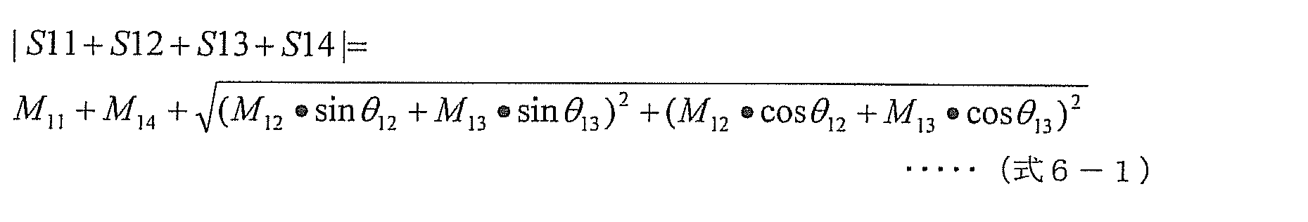
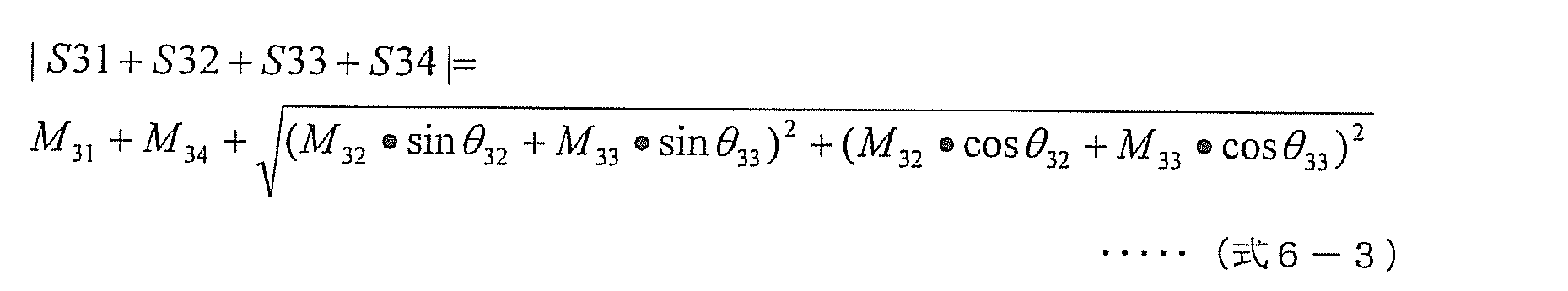
 本実施形態3による再サーチ処理は実施形態2で示した図17と同様の制御手順で行う。
<Re-search process>
The re-search process according to the third embodiment is performed by the same control procedure as that shown in FIG.
 本処理は、加熱処理中に被加熱物の温度や形状が変化することにより最適加熱条件が変化した場合でも、再サーチ処理により常に最適加熱条件の下に加熱できる。また、最良の照射効率を算出する際、設定周波数において各高周波電力ユニット140における反射電力およびスルー電力の振幅と位相とを個別に検出した結果を用いて、高周波電力発生部320a,320b,320c,320dの周波数と可変移相部142a,142b,142c,142dの移相量を任意の組み合わせに設定し動作させたと仮定したときの照射ロスを計算し、最も照射効率が良いそれぞれの高周波電力発生部320a,320b,320c,320dの周波数の値と各可変移相部142a,142b,142c,142dの移相量の値を決定することができる。 This process can always be heated under the optimum heating condition by the re-search process even when the optimum heating condition is changed by changing the temperature and shape of the object to be heated during the heating process. Further, when calculating the best irradiation efficiency, using the result of individually detecting the amplitude and phase of the reflected power and the through power at each high frequency power unit 140 at the set frequency, the high frequency power generators 320a, 320b, 320c, The irradiation loss is calculated when it is assumed that the frequency of 320d and the phase shift amount of the variable phase shifters 142a, 142b, 142c, 142d are set to an arbitrary combination and operated, and the respective high frequency power generators having the highest irradiation efficiency are calculated. The frequency value of 320a, 320b, 320c, 320d and the value of the phase shift amount of each variable phase shifter 142a, 142b, 142c, 142d can be determined.
 これにより、全ての、それぞれの高周波電力発生部320a,320b,320c,320dの周波数と各可変移相部142a,142b,142c,142dの全ての移相量の組み合わせを実測した場合と比較すると、上述の例の通りに、大幅な時間短縮が図れる。したがって、再サーチ処理を短時間に行うことができ、被加熱物の温度変化等によって再設定が必要な時間を含めた温め時間の延長を短くでき、ユーザの加熱の待ち時間を軽減できる。 Thereby, when compared with the case where all the combinations of the frequencies of the respective high- frequency power generators 320a, 320b, 320c, and 320d and the phase shift amounts of the variable phase shifters 142a, 142b, 142c, and 142d are measured, As described above, the time can be greatly reduced. Therefore, the re-search process can be performed in a short time, the extension of the warming time including the time that needs to be reset due to the temperature change of the object to be heated, etc. can be shortened, and the waiting time for heating by the user can be reduced.
 なお、再サーチにより算出した、ある周波数および位相条件における最良の照射効率の値が、現在の照射効率の値よりも良好となる場合であっても、たとえば、1つの高周波電力ユニット140における逆流電力の電力値が予め定められた閾値を超えてしまう条件であれば、選択する必要はない。つまり、各高周波電力ユニット140における逆流電力の電力値が、予め定められた閾値を超えない条件の中で、最良の照射効率となる条件を選び出してもよい。この閾値は、例えば、半導体素子を含んだ増幅器の故障を防ぐために、増幅器が持つ周波数毎の耐電圧特性によって決めればよい。 Even when the best irradiation efficiency value calculated by re-searching under a certain frequency and phase condition is better than the current irradiation efficiency value, for example, the backflow power in one high-frequency power unit 140 It is not necessary to select the power value if the power value exceeds a predetermined threshold value. That is, a condition that provides the best irradiation efficiency may be selected from the conditions in which the power value of the backflow power in each high-frequency power unit 140 does not exceed a predetermined threshold. This threshold value may be determined by the withstand voltage characteristic for each frequency of the amplifier, for example, in order to prevent failure of the amplifier including the semiconductor element.
 また、再サーチ処理の開始のタイミングは、前述の実施形態1と同様に、加熱処理中に常時もしくは定期的に、それぞれの高周波電力ユニット140a,140b,140c,140dから、同相検波信号I(1)~I(4)および直交検波信号Q(1)~Q(4)を取り込んで検出した反射電力の振幅と位相とから算出した電力値と、予め定められた閾値とを比較し、少なくとも1つ以上の高周波電力ユニット140における反射電力の電力値が、その閾値を越えた場合に実行してもよい。 Further, the timing of the start of the re-search process is the same as that in the first embodiment described above, from the high- frequency power units 140a, 140b, 140c, 140d from the respective high- frequency power units 140a, 140b, 140c, 140d, constantly or periodically during the heating process. ) To I (4) and quadrature detection signals Q (1) to Q (4) and the power value calculated from the amplitude and phase of the reflected power detected and compared with a predetermined threshold value, at least 1 You may perform when the electric power value of the reflected electric power in one or more high frequency electric power units 140 exceeds the threshold value.
 これにより、加熱処理中に被加熱物の温度や形状が変化することにより反射電力およびスルー電力の大きさが変化した場合でも、予め閾値を定め、これを超えた場合に再サーチ処理を行うことにより、常に最適加熱条件の下で被加熱物を加熱できる。 As a result, even if the reflected power and the through power change due to changes in the temperature and shape of the object to be heated during the heat treatment, a threshold value is set in advance and the re-search process is performed if the threshold is exceeded. Thus, the object to be heated can always be heated under optimum heating conditions.
 なお、前述したプレ・サーチ処理および再サーチ処理を実行する際に、サーチ処理中に過大な反射電力やスルー電力による、高周波加熱装置、特に半導体素子を含んだ増幅器の故障を防ぐ為に、それぞれの高周波電力ユニット140a,140b,140c,140dから出力する高周波電力の値を、本加熱の際の高周波電力の値よりも小さい値になるように、それぞれの高周波電力増幅部143a,143b,143c,143dの増幅利得を制御してもよい。 When performing the pre-search process and the re-search process described above, in order to prevent the failure of the high-frequency heating device, particularly the amplifier including the semiconductor element, due to excessive reflected power or through power during the search process. The high-frequency power amplification units 143a, 143b, 143c, 143c, 143c, 143c, 140c, 140d of the high- frequency power units 140a, 140b, 140c, 140d The amplification gain of 143d may be controlled.
 以上のように、本実施形態に係る高周波加熱装置300は、各高周波電力ユニット140に1対1に対応する高周波電力発生部320a~320dを備える。これにより、実施形態2に係る高周波加熱装置200と比較して、高周波電力ユニット140それぞれにおける反射電力の検出に要する時間をより一層短縮できる。よって、ユーザが高周波加熱装置300の使用開始ボタンを押して、実際に本加熱処理を行う前に、より短時間に最適な周波数の組み合わせ、および、移相量の組み合わせを決定することができ、ユーザの利便性をより一層向上させる。 As described above, the high-frequency heating apparatus 300 according to the present embodiment includes the high-frequency power generation units 320a to 320d corresponding to the high-frequency power units 140 on a one-to-one basis. Thereby, compared with the high frequency heating apparatus 200 which concerns on Embodiment 2, the time which the detection of the reflected electric power in each high frequency electric power unit 140 can be shortened further. Therefore, before the user presses the use start button of the high-frequency heating apparatus 300 and actually performs the main heat treatment, the optimum frequency combination and phase shift amount combination can be determined in a shorter time. To further improve convenience.
 また、実施形態2に係る高周波加熱装置200と比較して、高周波電力発生部320a~320dそれぞれが発生する高周波電力の周波数を互いに独立とできる。よって、高周波加熱装置300は、加熱室へ放射する複数の高周波電力の周波数における自由度が高くなるので、最大照射効率がより一層向上する。 Also, compared with the high-frequency heating device 200 according to the second embodiment, the frequencies of the high-frequency power generated by the high-frequency power generators 320a to 320d can be made independent of each other. Therefore, since the high frequency heating apparatus 300 has a high degree of freedom in the frequency of the plurality of high frequency powers radiated to the heating chamber, the maximum irradiation efficiency is further improved.
 以上、本発明に係る高周波加熱装置について、各実施形態に基づき説明したが、本発明はこれら実施形態に限定されるものではない。本発明の趣旨を逸脱しない限り、当業者が思いつく各種変形を当該実施形態に施したものや、異なる実施形態における構成要素を組み合わせて構築される形態も、本発明の範囲内に含まれる。 As mentioned above, although the high-frequency heating device concerning the present invention was explained based on each embodiment, the present invention is not limited to these embodiments. Unless it deviates from the meaning of this invention, the form which made the said embodiment the various deformation | transformation which those skilled in the art think, and the form constructed | assembled combining the component in a different embodiment are also contained in the scope of the present invention.
 このような高周波加熱装置は、例えば、図22に示す電子レンジとして適用可能であり、短時間で最適な加熱条件を検出し、被加熱物を加熱できる。よって、ユーザの利便性が向上する。 Such a high-frequency heating device can be applied, for example, as a microwave oven shown in FIG. 22, and can detect an optimum heating condition and heat an object to be heated in a short time. Therefore, user convenience is improved.
 なお、上記各実施形態において、第1~第4の高周波電力ユニット140a~140dのそれぞれが、可変移相部142a~142dを備えたが、実施形態2においては、第1~第4の高周波電力ユニット140a~140dのそれぞれが可変移相部を備えなくてもよい。 In each of the above embodiments, each of the first to fourth high-frequency power units 140a to 140d includes the variable phase shift units 142a to 142d. However, in the second embodiment, the first to fourth high-frequency power units Each of the units 140a to 140d may not include the variable phase shift unit.
 具体的には、実施形態2において、第1の高周波電力発生部220aと第1の分配部230aとの間に1つの可変移相部を備え、第2の高周波電力発生部220bと第2の分配部230bとの間に他の1つの可変移相部を備えてもよい。 Specifically, in the second embodiment, one variable phase shift unit is provided between the first high-frequency power generation unit 220a and the first distribution unit 230a, and the second high-frequency power generation unit 220b and the second high-frequency power generation unit 220b Another variable phase shift unit may be provided between the distribution unit 230b and the distribution unit 230b.
 また、実施形態2および3においては、第1~第4の高周波電力ユニット140a~140dのそれぞれは可変移相部142a~142dを備えず、高周波電力発生部(第1の高周波電力発生部220aおよび第2の高周波電力発生部220b、または、第1~第4の高周波電力発生部320a~320d)により発生される高周波電力の位相が変化されてもよい。つまり、可変移相部は、高周波電力発生部の各々に設けられ制御部(制御部110、210または310)から設定された移相量に従って、高周波電力発生部から発生される高周波電力の位相を変化させるPLL回路であってもよい。これにより、高周波電力発生部から発される高周波電力よりも低い周波数において位相を変化させることができ、制御および設計が容易になる。 In the second and third embodiments, each of the first to fourth high-frequency power units 140a to 140d does not include the variable phase shift units 142a to 142d, and the high-frequency power generation unit (the first high-frequency power generation unit 220a and the first high-frequency power generation unit 220a). The phase of the high-frequency power generated by the second high-frequency power generation unit 220b or the first to fourth high-frequency power generation units 320a to 320d) may be changed. That is, the variable phase shifting unit is configured to change the phase of the high frequency power generated from the high frequency power generating unit according to the phase shift amount provided in each of the high frequency power generating units and set from the control unit ( control unit 110, 210, or 310). A PLL circuit to be changed may be used. Thereby, the phase can be changed at a frequency lower than the high-frequency power generated from the high-frequency power generation unit, and control and design are facilitated.
 また、実施形態3において、上記説明では第1~第4の高周波電力発生部320a~320dが第1~第4の高周波電力ユニット140a~140dとは別に設けられていたが、第1~第4の高周波電力ユニット140a~140d内に、対応する第1~第4の高周波電力発生部320a~320dが設けられていてもよい。 In the third embodiment, the first to fourth high-frequency power generation units 320a to 320d are provided separately from the first to fourth high-frequency power units 140a to 140d in the above description. Corresponding first to fourth high-frequency power generators 320a to 320d may be provided in the high-frequency power units 140a to 140d.
 また、高周波加熱装置は、照射効率が最良となる周波数および移相量の組み合わせを設定するに限らず、所望の状態に被加熱物を加熱できるような周波数および移相量の組み合わせを決定し、決定した周波数および移相量の組み合わせで被加熱物を加熱してもよい。例えば、被加熱物がお弁当の場合に、ご飯は加熱して、おかずは加熱しないような、周波数および移相量の組み合わせを決定してもよい。 Further, the high-frequency heating device is not limited to setting the combination of the frequency and the amount of phase shift with the best irradiation efficiency, but determines the combination of the frequency and the amount of phase shift that can heat the object to be heated to a desired state, The object to be heated may be heated with a combination of the determined frequency and phase shift amount. For example, when the object to be heated is a lunch box, the combination of the frequency and the amount of phase shift may be determined such that the rice is heated and the side dishes are not heated.
 また、第1~第4の高周波電力ユニット140a~140dにおいて、高周波電力増幅部143a~143dは可変移相部142a~142dの後段に接続されていたが、高周波電力増幅部143a~143dが可変移相部142a~142dよりも前に接続されていてもよい。 In the first to fourth high-frequency power units 140a to 140d, the high-frequency power amplifiers 143a to 143d are connected to the subsequent stage of the variable phase shifters 142a to 142d, but the high-frequency power amplifiers 143a to 143d are variably shifted. It may be connected before the phase portions 142a to 142d.
 また、図9において、各高周波電力ユニット140の照射ロス180a~180dは、ステップS1101(具体的にはステップS1401、ステップS1404およびステップS1407)において設定した周波数毎に、実測に用いた移相量組み合わせθ0000以外の移相量組み合わせにおける照射ロスを計算により推定した。しかし、ステップS1101において設定した周波数に加え、さらに、高周波電力発生部(高周波電力発生部120、第1の高周波電力発生部220aおよび第2の高周波電力発生部220b、または、第1~第4の高周波電力発生部320a~320d)に設定可能な周波数(例えば、2401.5MHz等)における照射ロス180a~180dを、計算により推定してもよい。つまり、例えば設定可能な周波数が201ポイントある場合に、実測する周波数が101ポイント、推定する周波数が100ポイントであってもよい。 In FIG. 9, the irradiation losses 180a to 180d of each high-frequency power unit 140 are the phase shift amount combinations used in the actual measurement for each frequency set in step S1101 (specifically, step S1401, step S1404, and step S1407). Irradiation loss in combinations of phase shift amounts other than θ 0 , 0 , 0 , 0 was estimated by calculation. However, in addition to the frequency set in step S1101, a high frequency power generator (high frequency power generator 120, first high frequency power generator 220a and second high frequency power generator 220b, or first to fourth The irradiation losses 180a to 180d at frequencies (for example, 2401.5 MHz, etc.) that can be set in the high frequency power generators 320a to 320d) may be estimated by calculation. That is, for example, when there are 201 settable frequencies, the actually measured frequency may be 101 points and the estimated frequency may be 100 points.
 また、実施形態2及び3では、反射電力検出の制御手順を高周波電力発生部の周波数の関係に応じて異ならせていたが、周波数の組み合わせに関わらず、図5に示した実施形態1での反射電力検出の制御手順と同様にしてもよい。 In Embodiments 2 and 3, the reflected power detection control procedure is varied according to the frequency relationship of the high-frequency power generation unit. However, regardless of the combination of frequencies, the procedure in Embodiment 1 shown in FIG. You may make it the same as the control procedure of reflected power detection.
 同様に、実施形態2及び3では、スルー電力検出の制御手順を高周波電力発生部の周波数の関係に応じて異ならせていたが、周波数の組み合わせに関わらず、図6に示した実施形態1でのスルー電力検出の制御手順と同様にしてもよい。 Similarly, in the second and third embodiments, the control procedure of through power detection is varied according to the frequency relationship of the high-frequency power generation unit, but in the first embodiment shown in FIG. 6 regardless of the combination of frequencies. The same control procedure for through power detection may be used.
 また、本発明は、装置として実現できるだけでなく、この装置の処理手段をステップとする高周波加熱方法として実現することもできる。 The present invention can be realized not only as an apparatus but also as a high-frequency heating method using the processing means of this apparatus as a step.
 本発明は、少なくとも1つの高周波電力発生ユニットと複数の高周波電力ユニットを備える高周波加熱装置において、最適加熱条件の決定を短時間に行うことができるため、電子レンジなどの調理家電等として有用である。 INDUSTRIAL APPLICABILITY The present invention is useful as a cooking appliance such as a microwave oven because an optimum heating condition can be determined in a short time in a high-frequency heating apparatus including at least one high-frequency power generation unit and a plurality of high-frequency power units. .
100、200、300  高周波加熱装置
110、210、310  制御部
120          高周波電力発生部
121          発振部
122          位相同期ループ
123          増幅部
130、141、141a、141b、141c、141d  分配部
140          高周波電力ユニット
140a         第1の高周波電力ユニット
140b         第2の高周波電力ユニット
140c         第3の高周波電力ユニット
140d         第4の高周波電力ユニット
142、142a、142b、142c、142d   可変移相部
143、143a、143b、143c、143d   高周波電力増幅部
144、144a、144b、144c、144d   方向性結合部
145、145a、145b、145c、145d   直交検波部
150、150a、150b、150c、150d   放射部
151          可変減衰器
152          高周波電力増幅器
153          同相検波ミキサー
154          直交検波ミキサー
155          π/2移相器
156          同相出力側低域通過フィルター
157          直交出力側低域通過フィルター
170          Sパラメータ
180a~180d    照射ロス
220a、320a    第1の高周波電力発生部
220b、320b    第2の高周波電力発生部
230a         第1の分配部
230b         第2の分配部
320c         第3の高周波電力発生部
320d         第4の高周波電力発生部
100, 200, 300 High- frequency heating device 110, 210, 310 Control unit 120 High-frequency power generation unit 121 Oscillation unit 122 Phase-locked loop 123 Amplification unit 130, 141, 141a, 141b, 141c, 141d Distribution unit 140 High-frequency power unit 140a First High-frequency power unit 140b Second high-frequency power unit 140c Third high-frequency power unit 140d Fourth high- frequency power unit 142, 142a, 142b, 142c, 142d Variable phase shifter 143, 143a, 143b, 143c, 143d High-frequency power amplification Units 144, 144a, 144b, 144c, 144d Directional coupling units 145, 145a, 145b, 145c, 145d Quadrature detection units 150, 150a, 15 b, 150c, 150d Radiator 151 Variable attenuator 152 High-frequency power amplifier 153 In-phase detector mixer 154 Quadrature detector mixer 155 π / 2 phase shifter 156 In-phase output side low-pass filter 157 Quadrature output side low-pass filter 170 S parameter 180a ˜180d Irradiation loss 220a, 320a First high frequency power generation unit 220b, 320b Second high frequency power generation unit 230a First distribution unit 230b Second distribution unit 320c Third high frequency power generation unit 320d Fourth high frequency power Generator

Claims (20)

  1.  加熱室に収納された被加熱物を加熱する高周波加熱装置であって、
     設定された周波数の高周波電力を発生する少なくとも一つの高周波電力発生部と、
     前記高周波電力発生部で発生された高周波電力の位相を変化させる可変移相部と、
     前記可変移相部で位相が変化された高周波電力を前記加熱室に放射する放射部、および、前記放射部から放射された高周波電力の一部であって前記加熱室から前記放射部へ入射する逆流電力を検出する逆流電力検出部とを各々備えた複数の高周波電力ユニットと、
     前記高周波電力発生部に周波数を設定し、かつ、前記可変移相部に移相量を設定する制御部とを備え、
     前記逆流電力検出部は、
     前記制御部により前記高周波電力発生部に設定された周波数に基づいて、一の前記高周波電力ユニットの放射部から放射される高周波電力の一部が反射して当該一の前記高周波電力ユニットの放射部へ入力される反射による逆流電力である反射波の振幅および位相と、他の前記高周波電力ユニットの放射部から放射される高周波電力の一部が前記一の前記高周波電力ユニットの放射部へ入力される逆流電力であるスルー波の振幅および位相とを検出し、
     前記制御部は、
     前記高周波電力発生部に複数の周波数を順次設定し、設定した周波数ごとに各々の前記高周波電力ユニットの前記逆流電力検出部に前記反射波の振幅および位相と前記スルー波の振幅および位相とを検出させ、検出された複数の前記反射波の振幅および位相と前記スルー波の振幅および位相とに基づいて、被加熱物を加熱する際の、前記高周波電力発生部に発生させる高周波電力の周波数および前記可変移相部における移相量を決定し、決定した周波数および移相量を前記高周波電力発生部および前記可変移相部に設定する
     高周波加熱装置。
    A high-frequency heating device for heating an object to be heated stored in a heating chamber,
    At least one high-frequency power generation unit that generates high-frequency power of a set frequency;
    A variable phase shift unit that changes the phase of the high-frequency power generated by the high-frequency power generation unit;
    A radiating section that radiates high-frequency power whose phase has been changed by the variable phase-shifting section to the heating chamber, and a part of the high-frequency power radiated from the radiating section that is incident on the radiating section from the heating chamber. A plurality of high-frequency power units each including a backflow power detection unit for detecting backflow power;
    A control unit that sets a frequency in the high-frequency power generation unit and sets a phase shift amount in the variable phase shift unit;
    The backflow power detector is
    Based on the frequency set in the high-frequency power generation unit by the control unit, a part of the high-frequency power radiated from the radiation unit of the one high-frequency power unit is reflected, and the radiation unit of the one high-frequency power unit The amplitude and phase of the reflected wave, which is the backflow power caused by reflection, and a part of the high-frequency power radiated from the radiating part of the other high-frequency power unit are input to the radiating part of the one high-frequency power unit. Detect the amplitude and phase of the through wave,
    The controller is
    A plurality of frequencies are sequentially set in the high-frequency power generation unit, and the amplitude and phase of the reflected wave and the amplitude and phase of the through wave are detected in the backflow power detection unit of each high-frequency power unit for each set frequency. And the frequency of the high-frequency power to be generated in the high-frequency power generation unit when the object to be heated is heated based on the detected amplitude and phase of the reflected wave and the amplitude and phase of the through wave, and the A high-frequency heating apparatus that determines a phase shift amount in a variable phase shift unit and sets the determined frequency and phase shift amount in the high-frequency power generation unit and the variable phase shift unit.
  2.  前記制御部は、
     検出された前記反射波の振幅および位相と、前記スルー波の振幅および位相とを用いて、前記高周波電力発生部に設定可能な周波数ごとに、前記可変移相部における移相量の任意の組み合わせにおける前記反射波の振幅および位相と前記スルー波の振幅および位相とを計算により推測し、周波数ごとに検出された前記反射波の振幅および位相と前記スルー波の振幅および位相と、周波数ごとに推測した前記可変移相部における移相量の任意の組み合わせにおける前記反射波の振幅および位相と前記スルー波の振幅および位相とから、前記被加熱物を加熱する際の、前記高周波電力発生部に発生させる高周波電力の周波数および前記可変移相部における移相量の組み合わせを決定する
     請求項1に記載の高周波加熱装置。
    The controller is
    Using the detected amplitude and phase of the reflected wave and the amplitude and phase of the through wave, any combination of phase shift amounts in the variable phase shift unit for each frequency that can be set in the high frequency power generation unit The amplitude and phase of the reflected wave and the amplitude and phase of the through wave are estimated by calculation, and the amplitude and phase of the reflected wave and the amplitude and phase of the through wave that are detected for each frequency are estimated for each frequency. Generated in the high-frequency power generation unit when the object to be heated is heated from the amplitude and phase of the reflected wave and the amplitude and phase of the through wave in an arbitrary combination of phase shift amounts in the variable phase shift unit The high frequency heating apparatus according to claim 1, wherein a combination of a frequency of the high frequency power to be performed and a phase shift amount in the variable phase shift unit is determined.
  3.  前記制御部は、
     前記任意の組み合わせの中から、各々の前記高周波電力ユニットの前記逆流電力検出部で検出された前記反射波および前記スルー波の合計が最小となる前記組み合わせを決定する
     請求項2に記載の高周波加熱装置。
    The controller is
    The high frequency heating according to claim 2, wherein the combination that minimizes the sum of the reflected wave and the through wave detected by the backflow power detection unit of each of the high frequency power units is determined from the arbitrary combinations. apparatus.
  4.  前記逆流電力検出部は、直交検波部を有し、
     当該直交検波部は、前記逆流電力を前記高周波電力発生部で発生された高周波電力を用いて直交検波することにより、前記反射波の振幅および位相と、前記スルー波の振幅および位相とを算出するための同相検波信号および直交検波信号を検出する
     請求項2に記載の高周波加熱装置。
    The backflow power detection unit has a quadrature detection unit,
    The quadrature detection unit calculates the amplitude and phase of the reflected wave and the amplitude and phase of the through wave by performing quadrature detection of the backflow power using the high frequency power generated by the high frequency power generation unit. The high-frequency heating device according to claim 2, wherein an in-phase detection signal and a quadrature detection signal are detected.
  5.  前記複数の高周波電力ユニットの各々は、 前記高周波電力発生部で発生された高周波電力を増幅し、かつ当該増幅の利得が可変である高周波電力増幅部をさらに備え、
     前記制御部は、さらに、前記高周波電力増幅部における増幅利得を設定する
     請求項4に記載の高周波加熱装置。
    Each of the plurality of high-frequency power units further includes a high-frequency power amplifier that amplifies the high-frequency power generated by the high-frequency power generator and the gain of the amplification is variable,
    The high-frequency heating device according to claim 4, wherein the control unit further sets an amplification gain in the high-frequency power amplification unit.
  6.  前記高周波加熱装置は、
     1つの前記高周波電力発生部と、複数の前記高周波電力ユニットとを有し、
     さらに、1つの前記高周波電力発生部で発生された高周波電力を分配し、分配した高周波電力を前記複数の高周波電力ユニットに供給する分配部を備える
     請求項5に記載の高周波加熱装置。
    The high-frequency heating device includes:
    One high-frequency power generation unit, and a plurality of the high-frequency power units,
    The high-frequency heating device according to claim 5, further comprising a distribution unit that distributes the high-frequency power generated by one of the high-frequency power generation units and supplies the distributed high-frequency power to the plurality of high-frequency power units.
  7.  前記制御部は、
     一の前記高周波電力ユニットにおける前記逆流電力検出部が前記スルー波の振幅および位相を検出する際に、
     前記高周波電力発生部の周波数を前記スルー波測定用の周波数に設定し、かつ、前記スルー波の振幅に比べて、当該一の高周波電力ユニットにおける前記反射波の振幅が小さくなるように、前記高周波電力増幅部における増幅利得を設定する
     請求項6に記載の高周波加熱装置。
    The controller is
    When the backflow power detection unit in one high frequency power unit detects the amplitude and phase of the through wave,
    The frequency of the high-frequency power generator is set to the frequency for measuring the through-wave, and the high-frequency power is generated so that the amplitude of the reflected wave in the one high-frequency power unit is smaller than the amplitude of the through-wave. The high frequency heating device according to claim 6, wherein an amplification gain in the power amplification unit is set.
  8.  前記制御部は、
     一の前記高周波電力ユニットにおける前記逆流電力検出部が、前記反射波の振幅および位相を検出する際に、
     当該一の前記高周波電力ユニットにおける前記反射波の振幅に比べて前記スルー波の振幅が小さくなるように、前記高周波電力増幅部における増幅利得を設定する
     請求項6に記載の高周波加熱装置。
    The controller is
    When the backflow power detection unit in the one high-frequency power unit detects the amplitude and phase of the reflected wave,
    The high-frequency heating device according to claim 6, wherein an amplification gain in the high-frequency power amplification unit is set so that an amplitude of the through wave is smaller than an amplitude of the reflected wave in the one high-frequency power unit.
  9.  前記高周波加熱装置は、
     複数の前記高周波電力発生部を有し、
     複数の前記高周波電力発生部は、発生した複数の高周波電力を前記複数の高周波電力ユニットに供給する
     請求項5に記載の高周波加熱装置。
    The high-frequency heating device includes:
    A plurality of the high-frequency power generators;
    The high-frequency heating device according to claim 5, wherein the plurality of high-frequency power generation units supply the generated plurality of high-frequency powers to the plurality of high-frequency power units.
  10.  複数の前記高周波電力発生部の1つと、前記複数の高周波電力ユニットとは、1対1に対応して設けられている
     請求項9に記載の高周波加熱装置。
    The high frequency heating apparatus according to claim 9, wherein one of the plurality of high frequency power generation units and the plurality of high frequency power units are provided in a one-to-one correspondence.
  11.  前記複数の高周波電力ユニットは、複数の前記高周波電力発生部に対応して設けられ、
     前記制御部は、
     一の前記高周波電力ユニットにおける前記逆流電力検出部が、前記スルー波の振幅および位相を検出する際に、
     当該一の前記高周波電力ユニットに対応する高周波電力発生部と、他の一の前記高周波電力ユニットに対応する高周波電力発生部とに同一の周波数を設定し、かつ、前記スルー波の振幅に比べて、当該一の前記高周波電力ユニットにおける前記反射波の振幅が小さくなるように、前記高周波電力増幅部における増幅利得を設定する
     請求項9または10に記載の高周波加熱装置。
    The plurality of high frequency power units are provided corresponding to the plurality of high frequency power generation units,
    The controller is
    When the backflow power detection unit in one high frequency power unit detects the amplitude and phase of the through wave,
    The same frequency is set in the high-frequency power generation unit corresponding to the one high-frequency power unit and the high-frequency power generation unit corresponding to the other one high-frequency power unit, and compared with the amplitude of the through wave The high-frequency heating device according to claim 9 or 10, wherein an amplification gain in the high-frequency power amplification unit is set so that an amplitude of the reflected wave in the one high-frequency power unit is small.
  12.  前記複数の高周波電力ユニットは、複数の前記高周波電力発生部に対応して設けられ、
     前記制御部は、
     一の前記高周波電力ユニットに対応する高周波電力発生部に設定した周波数と、他の一の前記高周波電力ユニットに対応する高周波電力発生部に設定した周波数とが等しい、かつ、当該一の前記高周波電力ユニットにおける前記逆流電力検出部が、前記反射波の振幅および位相を検出する際に、
     当該一の前記高周波電力ユニットにおける前記反射波の振幅に比べて、当該一の前記高周波電力ユニットにおける前記スルー波の振幅が小さくなるように、前記高周波電力増幅部における増幅利得を設定する
     請求項9または10に記載の高周波加熱装置。
    The plurality of high frequency power units are provided corresponding to the plurality of high frequency power generation units,
    The controller is
    The frequency set in the high-frequency power generation unit corresponding to the one high-frequency power unit is equal to the frequency set in the high-frequency power generation unit corresponding to the other one high-frequency power unit, and the one high-frequency power When the backflow power detection unit in the unit detects the amplitude and phase of the reflected wave,
    The amplification gain in the high-frequency power amplification unit is set so that the amplitude of the through wave in the one high-frequency power unit is smaller than the amplitude of the reflected wave in the one high-frequency power unit. Or the high-frequency heating device according to 10.
  13.  前記制御部は、前記高周波電力発生部の周波数および前記可変移相部の移相量の決定を、前記被加熱物に対する加熱処理前に、プレ・サーチ処理として実行する、および、前記高周波電力発生部の周波数および前記可変移相部の移相量の再決定を、前記被加熱物に対する加熱処理中に、再サーチ処理として実行し、当該プレ・サーチ処理または当該再サーチ処理の実行時に、前記複数の高周波電力ユニットの前記放射部から放射される高周波電力が、加熱処理時に当該放射部から放射される高周波電力よりも小さい値となるように、前記複数の高周波電力ユニットの各々の前記高周波電力増幅部の増幅利得を設定する
     請求項5から12のいずれか1項に記載の高周波加熱装置。
    The control unit executes the determination of the frequency of the high-frequency power generation unit and the phase shift amount of the variable phase shift unit as a pre-search process before the heating process for the object to be heated, and the generation of the high-frequency power Re-determination of the frequency of the part and the phase shift amount of the variable phase shift part is performed as a re-search process during the heating process for the object to be heated, and when the pre-search process or the re-search process is performed, The high-frequency power of each of the plurality of high-frequency power units is such that the high-frequency power radiated from the radiating unit of the plurality of high-frequency power units has a value smaller than the high-frequency power radiated from the radiating unit during the heat treatment. The high frequency heating apparatus according to any one of claims 5 to 12, wherein an amplification gain of the amplification unit is set.
  14.  前記制御部は、前記高周波電力発生部の周波数および前記可変移相部の移相量の決定を、前記被加熱物に対する加熱処理前に、プレ・サーチ処理として実行する
     請求項1から4のいずれか1項に記載の高周波加熱装置。
    The said control part performs the determination of the frequency of the said high frequency electric power generation part, and the phase shift amount of the said variable phase shift part as a pre-search process before the heat processing with respect to the said to-be-heated material. The high-frequency heating device according to claim 1.
  15.  前記制御部は、さらに、
     前記高周波電力発生部の周波数および前記可変移相部の移相量の再決定を、前記被加熱物に対する加熱処理中に、再サーチ処理として実行し、
     前記再サーチ処理で決定された新たな周波数を前記高周波電力発生部に設定し、新たな移相量を前記可変移相部に設定する
     請求項1から4のいずれか1項に記載の高周波加熱装置。
    The control unit further includes:
    Re-determination of the frequency of the high-frequency power generation unit and the phase shift amount of the variable phase shift unit is performed as a re-search process during the heating process for the object to be heated,
    5. The high-frequency heating according to claim 1, wherein a new frequency determined by the re-search process is set in the high-frequency power generation unit, and a new phase shift amount is set in the variable phase shift unit. apparatus.
  16.  前記制御部は、前記被加熱物に対する加熱処理中に、前記複数の高周波電力ユニットの各々に前記逆流電力を検出させ、
     検出させた複数の逆流電力の少なくとも1つが閾値を超えた場合に前記再サーチ処理を実行する
     請求項15に記載の高周波加熱装置。
    The control unit causes each of the plurality of high-frequency power units to detect the backflow power during the heat treatment on the object to be heated,
    The high frequency heating device according to claim 15, wherein the re-search process is executed when at least one of the detected plurality of backflow powers exceeds a threshold value.
  17.  前記可変移相部は、
     前記複数の高周波電力ユニットの各々に対応して設けられた移相器である
     請求項1に記載の高周波加熱装置。
    The variable phase shifter is
    The high frequency heating apparatus according to claim 1, wherein the phase shifter is provided corresponding to each of the plurality of high frequency power units.
  18.  前記可変移相部は、
     前記少なくとも1つの高周波電力発生部の各々に対応して設けられ、前記制御部から設定された移相量に従って対応する前記高周波電力発生部から発生される高周波電力の位相を変化させるPLL(Phase Locked Loop)回路である
     請求項1に記載の高周波加熱装置。
    The variable phase shifter is
    A PLL (Phase Locked) that is provided corresponding to each of the at least one high-frequency power generation unit and changes the phase of the high-frequency power generated from the high-frequency power generation unit corresponding to the phase shift amount set by the control unit. The high-frequency heating device according to claim 1, wherein the high-frequency heating device is a Loop circuit.
  19.  加熱室に収納された被加熱物を複数の高周波電力ユニットから放射される高周波電力によって加熱する高周波加熱方法であって、
     前記複数の高周波電力ユニットから放射される高周波電力の周波数を設定する設定ステップと、
     設定された周波数に基づいて、一の前記高周波電力ユニットから放射される高周波電力の一部が反射して当該一の前記高周波電力ユニットへ入力される反射による逆流電力である反射波の振幅および位相と、他の前記高周波電力ユニットから放射される高周波電力の一部が前記一の前記高周波電力ユニットへ入力される逆流電力であるスルー波の振幅および位相とを検出する第1検出ステップと、
     前記複数の高周波電力ユニットから放射される高周波電力の周波数を変更して設定する変更ステップと、
     前記変更ステップで設定された周波数に基づいて、前記反射波の振幅および位相と、前記スルー波の振幅および位相とを検出する第2検出ステップと、
     前記第1検出ステップおよび前記第2検出ステップで検出された前記反射波の振幅および位相と前記スルー波の振幅および位相とに基づいて、前記被加熱物を加熱する際の、前記複数の高周波電力ユニットから放射される高周波電力の周波数および位相を決定する決定ステップと、
     決定された周波数および位相の高周波電力を前記複数の高周波電力ユニットから放射することにより、前記被加熱物を加熱する加熱ステップとを含む
     高周波加熱方法。
    A high-frequency heating method for heating an object to be heated stored in a heating chamber with high-frequency power radiated from a plurality of high-frequency power units,
    A setting step for setting a frequency of the high-frequency power radiated from the plurality of high-frequency power units;
    Based on the set frequency, a part of the high-frequency power radiated from the one high-frequency power unit is reflected, and the amplitude and phase of the reflected wave that is the backflow power due to the reflection input to the one high-frequency power unit. And a first detection step of detecting an amplitude and a phase of a through wave, which is a reverse flow power that is input to the one high frequency power unit, part of the high frequency power radiated from the other high frequency power unit;
    A change step of changing and setting the frequency of the high frequency power radiated from the plurality of high frequency power units;
    A second detection step of detecting the amplitude and phase of the reflected wave and the amplitude and phase of the through wave based on the frequency set in the changing step;
    The plurality of high-frequency powers when the object to be heated is heated based on the amplitude and phase of the reflected wave and the amplitude and phase of the through wave detected in the first detection step and the second detection step A determining step for determining the frequency and phase of the high-frequency power emitted from the unit;
    A heating step of heating the object to be heated by radiating high-frequency power having a determined frequency and phase from the plurality of high-frequency power units.
  20.  前記決定ステップは、
     前記第1検出ステップおよび前記第2検出ステップで検出された前記反射波の振幅および位相と、前記スルー波の振幅および位相とを用いて、前記複数の高周波電力ユニットから放射される高周波電力の設定可能な周波数ごとに、前記複数の高周波電力ユニットから放射された高周波電力の位相の任意の組み合わせにおける前記反射波の振幅および位相と、前記スルー波の振幅および位相とを、前記反射波の振幅および位相と前記スルー波の振幅および位相とを用いて計算することで推測する推測ステップと、
     前記第1検出ステップおよび前記第2検出ステップで検出された前記反射波の振幅および位相と前記スルー波の振幅および位相と、前記推測ステップで推測された前記反射波の振幅および位相と前記反射波の振幅および位相とから、前記被加熱物を加熱する際の、前記複数の高周波電力ユニットから放射される高周波電力の周波数および位相の組み合わせを決定する組み合わせステップとを含む
     請求項19に記載の高周波加熱方法。
     
     
    The determining step includes
    Setting of high frequency power radiated from the plurality of high frequency power units using the amplitude and phase of the reflected wave detected in the first detection step and the second detection step and the amplitude and phase of the through wave For each possible frequency, the amplitude and phase of the reflected wave and the amplitude and phase of the through wave in any combination of the phases of the high-frequency power radiated from the plurality of high-frequency power units, and the amplitude of the reflected wave and An estimation step for estimating by calculating using the phase and the amplitude and phase of the through wave;
    The amplitude and phase of the reflected wave detected in the first detection step and the second detection step, the amplitude and phase of the through wave, the amplitude and phase of the reflected wave estimated in the estimation step, and the reflected wave The combination step of determining the combination of the frequency and phase of the high frequency power radiated from the plurality of high frequency power units when the object to be heated is heated from the amplitude and phase of the high frequency Heating method.

PCT/JP2010/005631 2009-09-29 2010-09-15 High-frequency heating device and high-frequency heating method WO2011039961A1 (en)

Priority Applications (4)

Application Number Priority Date Filing Date Title
EP10820087.4A EP2485565A4 (en) 2009-09-29 2010-09-15 High-frequency heating device and high-frequency heating method
CN2010800300646A CN102474924B (en) 2009-09-29 2010-09-15 High-frequency heating device and high-frequency heating method
JP2011534054A JP4995350B2 (en) 2009-09-29 2010-09-15 High frequency heating apparatus and high frequency heating method
US13/382,222 US8796593B2 (en) 2009-09-29 2010-09-15 Radio-frequency heating apparatus and radio-frequency heating method

Applications Claiming Priority (2)

Application Number Priority Date Filing Date Title
JP2009225651 2009-09-29
JP2009-225651 2009-09-29

Publications (1)

Publication Number Publication Date
WO2011039961A1 true WO2011039961A1 (en) 2011-04-07

Family

ID=43825814

Family Applications (1)

Application Number Title Priority Date Filing Date
PCT/JP2010/005631 WO2011039961A1 (en) 2009-09-29 2010-09-15 High-frequency heating device and high-frequency heating method

Country Status (5)

Country Link
US (1) US8796593B2 (en)
EP (1) EP2485565A4 (en)
JP (1) JP4995350B2 (en)
CN (1) CN102474924B (en)
WO (1) WO2011039961A1 (en)

Cited By (16)

* Cited by examiner, † Cited by third party
Publication number Priority date Publication date Assignee Title
JP2017504159A (en) * 2013-12-23 2017-02-02 ワールプール コーポレイション Method for calibrating a multi-feed high-frequency device
US10560986B2 (en) 2013-08-20 2020-02-11 Whirlpool Corporation Method for detecting the status of popcorn in a microwave
US10764970B2 (en) 2016-01-08 2020-09-01 Whirlpool Corporation Multiple cavity microwave oven insulated divider
US10772165B2 (en) 2018-03-02 2020-09-08 Whirlpool Corporation System and method for zone cooking according to spectromodal theory in an electromagnetic cooking device
US10820382B2 (en) 2016-01-28 2020-10-27 Whirlpool Corporation Method and apparatus for delivering radio frequency electromagnetic energy to cook foodstuff
US10827570B2 (en) 2016-02-15 2020-11-03 Whirlpool Corporation Method and apparatus for delivering radio frequency electromagnetic energy to cook foodstuff
US10827569B2 (en) 2017-09-01 2020-11-03 Whirlpool Corporation Crispness and browning in full flat microwave oven
US10904962B2 (en) 2015-06-03 2021-01-26 Whirlpool Corporation Method and device for electromagnetic cooking
US10904961B2 (en) 2015-03-06 2021-01-26 Whirlpool Corporation Method of calibrating a high power amplifier for a radio frequency power measurement system
US10912160B2 (en) 2018-07-19 2021-02-02 Whirlpool Corporation Cooking appliance
US10993293B2 (en) 2013-12-23 2021-04-27 Whirlpool Corporation Interrupting circuit for a radio frequency generator
US11039510B2 (en) 2017-09-27 2021-06-15 Whirlpool Corporation Method and device for electromagnetic cooking using asynchronous sensing strategy for resonant modes real-time tracking
US11191133B2 (en) 2014-09-17 2021-11-30 Whirlpool Corporation Direct heating through patch antennas
EP2637477B1 (en) * 2012-03-05 2022-03-09 Whirlpool Corporation Microwave heating apparatus
US11404758B2 (en) 2018-05-04 2022-08-02 Whirlpool Corporation In line e-probe waveguide transition
US11483905B2 (en) 2016-01-08 2022-10-25 Whirlpool Corporation Method and apparatus for determining heating strategies

Families Citing this family (41)

* Cited by examiner, † Cited by third party
Publication number Priority date Publication date Assignee Title
US8653482B2 (en) 2006-02-21 2014-02-18 Goji Limited RF controlled freezing
CN104219810B (en) 2008-11-10 2016-03-23 高知有限公司 The equipment using RF energy to carry out heating and method
JP5713411B2 (en) 2009-11-10 2015-05-07 ゴジ リミテッド Device and method for heating using RF energy
US9265097B2 (en) * 2010-07-01 2016-02-16 Goji Limited Processing objects by radio frequency (RF) energy
EP2469975B1 (en) * 2010-12-21 2016-05-11 Whirlpool Corporation Control of microwave source efficiency in a microwave heating apparatus
CN104350810B (en) * 2012-06-07 2016-08-24 松下知识产权经营株式会社 Thermatron
WO2014006510A2 (en) 2012-07-02 2014-01-09 Goji Ltd. Rf energy application based on electromagnetic feedback
US9043525B2 (en) * 2012-12-14 2015-05-26 Lam Research Corporation Optimizing a rate of transfer of data between an RF generator and a host system within a plasma tool
EP3087806B1 (en) * 2013-12-23 2021-06-09 Whirlpool Corporation Method of control of a multifeed radio frequency device
JP2017525121A (en) 2014-05-28 2017-08-31 グァンドン ミデア キッチン アプライアンシズ マニュファクチュアリング カンパニー リミテッド Semiconductor microwave oven and semiconductor microwave source
CN104676671A (en) * 2014-05-28 2015-06-03 广东美的厨房电器制造有限公司 Semiconductor microwave oven and semiconductor microwave source thereof
CN104676670A (en) * 2014-05-28 2015-06-03 广东美的厨房电器制造有限公司 Semiconductor microwave oven and semiconductor microwave source thereof
EP2983290B1 (en) * 2014-08-07 2017-12-20 Nxp B.V. Circuit for detecting phase shift applied to an RF signal
CN104654381B (en) * 2015-02-12 2017-08-04 广东美的厨房电器制造有限公司 Semiconductor microwave oven and the semiconductor power source for micro-wave oven
US10412794B2 (en) * 2016-03-11 2019-09-10 Illinois Tool Works Inc. Microwave heating device and method for operating a microwave heating device
US10772166B2 (en) * 2016-03-11 2020-09-08 Illinois Tool Works, Inc. Microwave heating device
US10327289B2 (en) * 2016-04-01 2019-06-18 Illinois Tool Works Inc. Microwave heating device and method for operating a microwave heating device
CN109315029B (en) * 2016-06-30 2021-12-07 松下知识产权经营株式会社 High-frequency heating device
CN109565913B (en) 2016-09-22 2021-12-24 松下电器产业株式会社 Method and system for radio frequency electromagnetic energy transfer
EP3530075A4 (en) 2016-10-19 2020-05-27 Whirlpool Corporation Method and device for electromagnetic cooking using closed loop control
EP3530074A4 (en) 2016-10-19 2020-05-27 Whirlpool Corporation Food load cooking time modulation
EP3529536B1 (en) 2016-10-19 2021-07-14 Whirlpool Corporation System and method for food preparation utilizing a multi-layer model
CN109691226B (en) * 2016-12-21 2021-07-16 松下电器产业株式会社 Electromagnetic energy transfer system, method for generating radio frequency signal and radio frequency channel
WO2018118065A1 (en) 2016-12-22 2018-06-28 Whirlpool Corporation Method and device for electromagnetic cooking using non-centered loads
US11202348B2 (en) 2016-12-22 2021-12-14 Whirlpool Corporation Method and device for electromagnetic cooking using non-centered loads management through spectromodal axis rotation
WO2018118077A1 (en) 2016-12-23 2018-06-28 Whirlpool Corporation Method of diagnosing an electromagnetic cooking device
US11690147B2 (en) * 2016-12-29 2023-06-27 Whirlpool Corporation Electromagnetic cooking device with automatic boiling detection and method of controlling cooking in the electromagnetic cooking device
EP3563632B1 (en) 2016-12-29 2023-01-18 Whirlpool Corporation Electromagnetic cooking device with automatic popcorn popping feature and method of controlling cooking in the electromagnetic device
EP3563636B1 (en) 2016-12-29 2021-10-13 Whirlpool Corporation System and method for controlling power for a cooking device
WO2018125149A1 (en) * 2016-12-29 2018-07-05 Whirlpool Corporation Electromagnetic cooking device with automatic melt operation and method of controlling cooking in the electromagnetic cooking device
US11432379B2 (en) 2016-12-29 2022-08-30 Whirlpool Corporation Electromagnetic cooking device with automatic liquid heating and method of controlling cooking in the electromagnetic cooking device
EP3563637B1 (en) 2016-12-29 2022-07-27 Whirlpool Corporation Electromagnetic cooking device with automatic anti-splatter operation and method of controlling cooking in the electromagnetic device
US11483906B2 (en) 2016-12-29 2022-10-25 Whirlpool Corporation System and method for detecting cooking level of food load
WO2018125136A1 (en) 2016-12-29 2018-07-05 Whirlpool Corporation System and method for controlling a heating distribution in an electromagnetic cooking device
US11343883B2 (en) 2016-12-29 2022-05-24 Whirlpool Corporation Detecting changes in food load characteristics using Q-factor
US11452182B2 (en) 2016-12-29 2022-09-20 Whirlpool Corporation System and method for detecting changes in food load characteristics using coefficient of variation of efficiency
WO2018125137A1 (en) 2016-12-29 2018-07-05 Whirlpool Corporation System and method for analyzing a frequency response of an electromagnetic cooking device
WO2018125182A1 (en) 2016-12-30 2018-07-05 Whirlpool Corporation Cost effective hybrid protection for high power amplifier.
US11013357B2 (en) * 2017-03-06 2021-05-25 Illinois Tool Works Inc. Modified S-parameter measurement and usage in solid state RF oven electronics
US11576408B2 (en) * 2019-04-15 2023-02-14 Bsh Home Appliances Corporation Ice processing system
KR20210125289A (en) * 2020-04-08 2021-10-18 엘지전자 주식회사 Oven includes a plurality of antennas and method of control the same

Citations (7)

* Cited by examiner, † Cited by third party
Publication number Priority date Publication date Assignee Title
JP2006523921A (en) * 2003-04-16 2006-10-19 リム テクノロジーズ コーポレイション エヌ・ヴェ Microwave or radio wave device including three decoupled oscillators
JP2008108491A (en) * 2006-10-24 2008-05-08 Matsushita Electric Ind Co Ltd Microwave treatment device
WO2009011111A1 (en) * 2007-07-13 2009-01-22 Panasonic Corporation Microwave heating device
JP2009032638A (en) 2007-07-05 2009-02-12 Panasonic Corp Microwave processing device
JP2009301747A (en) * 2008-06-10 2009-12-24 Panasonic Corp Large high frequency power device
JP2010004453A (en) * 2008-06-23 2010-01-07 Panasonic Corp High frequency power amplifier and high frequency power output device with high frequency power amplifier
WO2010140342A1 (en) * 2009-06-01 2010-12-09 パナソニック株式会社 High-frequency heating device and high-frequency heating method

Family Cites Families (14)

* Cited by examiner, † Cited by third party
Publication number Priority date Publication date Assignee Title
JP2522199B2 (en) 1994-04-20 1996-08-07 日本電気株式会社 Power amplifier
JP3804129B2 (en) 1996-11-12 2006-08-02 株式会社トキメック Densitometer
US5963840A (en) * 1996-11-13 1999-10-05 Applied Materials, Inc. Methods for depositing premetal dielectric layer at sub-atmospheric and high temperature conditions
US5968587A (en) * 1996-11-13 1999-10-19 Applied Materials, Inc. Systems and methods for controlling the temperature of a vapor deposition apparatus
US6015465A (en) * 1998-04-08 2000-01-18 Applied Materials, Inc. Temperature control system for semiconductor process chamber
JP2000357583A (en) 1999-06-15 2000-12-26 Mitsubishi Electric Corp Microwave oven
US7602127B2 (en) * 2005-04-18 2009-10-13 Mks Instruments, Inc. Phase and frequency control of a radio frequency generator from an external source
JP5138164B2 (en) 2005-11-25 2013-02-06 パナソニック株式会社 Power control apparatus for high frequency dielectric heating and control method thereof
EP1954098B1 (en) 2005-11-25 2016-09-14 Panasonic Corporation Power control device for high-frequency dielectric heating and its control method
JP5064924B2 (en) 2006-08-08 2012-10-31 パナソニック株式会社 Microwave processing equipment
JP4940922B2 (en) 2006-12-08 2012-05-30 パナソニック株式会社 Microwave processing equipment
JP5167678B2 (en) 2007-04-16 2013-03-21 パナソニック株式会社 Microwave processing equipment
JP5127038B2 (en) 2007-12-03 2013-01-23 パナソニック株式会社 High frequency processing equipment
JP5092863B2 (en) 2008-04-17 2012-12-05 パナソニック株式会社 Microwave processing equipment

Patent Citations (7)

* Cited by examiner, † Cited by third party
Publication number Priority date Publication date Assignee Title
JP2006523921A (en) * 2003-04-16 2006-10-19 リム テクノロジーズ コーポレイション エヌ・ヴェ Microwave or radio wave device including three decoupled oscillators
JP2008108491A (en) * 2006-10-24 2008-05-08 Matsushita Electric Ind Co Ltd Microwave treatment device
JP2009032638A (en) 2007-07-05 2009-02-12 Panasonic Corp Microwave processing device
WO2009011111A1 (en) * 2007-07-13 2009-01-22 Panasonic Corporation Microwave heating device
JP2009301747A (en) * 2008-06-10 2009-12-24 Panasonic Corp Large high frequency power device
JP2010004453A (en) * 2008-06-23 2010-01-07 Panasonic Corp High frequency power amplifier and high frequency power output device with high frequency power amplifier
WO2010140342A1 (en) * 2009-06-01 2010-12-09 パナソニック株式会社 High-frequency heating device and high-frequency heating method

Non-Patent Citations (1)

* Cited by examiner, † Cited by third party
Title
See also references of EP2485565A4 *

Cited By (17)

* Cited by examiner, † Cited by third party
Publication number Priority date Publication date Assignee Title
EP2637477B1 (en) * 2012-03-05 2022-03-09 Whirlpool Corporation Microwave heating apparatus
US10560986B2 (en) 2013-08-20 2020-02-11 Whirlpool Corporation Method for detecting the status of popcorn in a microwave
US11102855B2 (en) 2013-08-20 2021-08-24 Whirlpool Corporation Method for detecting the status of popcorn in a microwave
JP2017504159A (en) * 2013-12-23 2017-02-02 ワールプール コーポレイション Method for calibrating a multi-feed high-frequency device
US10993293B2 (en) 2013-12-23 2021-04-27 Whirlpool Corporation Interrupting circuit for a radio frequency generator
US11191133B2 (en) 2014-09-17 2021-11-30 Whirlpool Corporation Direct heating through patch antennas
US10904961B2 (en) 2015-03-06 2021-01-26 Whirlpool Corporation Method of calibrating a high power amplifier for a radio frequency power measurement system
US10904962B2 (en) 2015-06-03 2021-01-26 Whirlpool Corporation Method and device for electromagnetic cooking
US10764970B2 (en) 2016-01-08 2020-09-01 Whirlpool Corporation Multiple cavity microwave oven insulated divider
US11483905B2 (en) 2016-01-08 2022-10-25 Whirlpool Corporation Method and apparatus for determining heating strategies
US10820382B2 (en) 2016-01-28 2020-10-27 Whirlpool Corporation Method and apparatus for delivering radio frequency electromagnetic energy to cook foodstuff
US10827570B2 (en) 2016-02-15 2020-11-03 Whirlpool Corporation Method and apparatus for delivering radio frequency electromagnetic energy to cook foodstuff
US10827569B2 (en) 2017-09-01 2020-11-03 Whirlpool Corporation Crispness and browning in full flat microwave oven
US11039510B2 (en) 2017-09-27 2021-06-15 Whirlpool Corporation Method and device for electromagnetic cooking using asynchronous sensing strategy for resonant modes real-time tracking
US10772165B2 (en) 2018-03-02 2020-09-08 Whirlpool Corporation System and method for zone cooking according to spectromodal theory in an electromagnetic cooking device
US11404758B2 (en) 2018-05-04 2022-08-02 Whirlpool Corporation In line e-probe waveguide transition
US10912160B2 (en) 2018-07-19 2021-02-02 Whirlpool Corporation Cooking appliance

Also Published As

Publication number Publication date
JP4995350B2 (en) 2012-08-08
EP2485565A4 (en) 2013-05-15
US20120103972A1 (en) 2012-05-03
EP2485565A1 (en) 2012-08-08
JPWO2011039961A1 (en) 2013-02-21
CN102474924B (en) 2013-08-14
US8796593B2 (en) 2014-08-05
CN102474924A (en) 2012-05-23

Similar Documents

Publication Publication Date Title
JP4995350B2 (en) High frequency heating apparatus and high frequency heating method
JP4976591B2 (en) High frequency heating apparatus and high frequency heating method
CN101502170B (en) Microwave processing apparatus
US9398646B2 (en) Microwave heating device and microwave heating control method
RU2483495C2 (en) Microwave heating device
EP2677839A1 (en) Microwave heating apparatus with multi-feeding points
US20140008357A1 (en) Microwave power source and method of automatic adjustement of operation frequence
WO2018125145A1 (en) System and method for detecting changes in food load characteristics using coefficient of variation of efficiency
EP3563633A1 (en) System and method for detecting cooking level of food load
JP4839994B2 (en) Microwave equipment
WO2018125136A1 (en) System and method for controlling a heating distribution in an electromagnetic cooking device
CN105338675B (en) A kind of high-frequency electromagnetic heating equipment and its electrical control method
JP2008060016A (en) Microwave utilization device
KR20120071986A (en) A cooking apparatus
US20190394841A1 (en) Variable time division multiplexing of electric field modes for zonal microwave cooking
EP3560291A1 (en) Method and device for electromagnetic cooking using non-centered loads management through spectromodal axis rotation
WO2018118065A1 (en) Method and device for electromagnetic cooking using non-centered loads
WO2018075026A1 (en) Method and device for electromagnetic cooking using closed loop control
JP2010272216A (en) Microwave treatment device
KR20110026807A (en) A cooking apparatus using microwave

Legal Events

Date Code Title Description
WWE Wipo information: entry into national phase

Ref document number: 201080030064.6

Country of ref document: CN

121 Ep: the epo has been informed by wipo that ep was designated in this application

Ref document number: 10820087

Country of ref document: EP

Kind code of ref document: A1

WWE Wipo information: entry into national phase

Ref document number: 2010820087

Country of ref document: EP

WWE Wipo information: entry into national phase

Ref document number: 13382222

Country of ref document: US

WWE Wipo information: entry into national phase

Ref document number: 2011534054

Country of ref document: JP

NENP Non-entry into the national phase

Ref country code: DE