WO2011039904A1 - パノラマ画像表示装置およびパノラマ画像表示方法 - Google Patents
パノラマ画像表示装置およびパノラマ画像表示方法 Download PDFInfo
- Publication number
- WO2011039904A1 WO2011039904A1 PCT/JP2010/003362 JP2010003362W WO2011039904A1 WO 2011039904 A1 WO2011039904 A1 WO 2011039904A1 JP 2010003362 W JP2010003362 W JP 2010003362W WO 2011039904 A1 WO2011039904 A1 WO 2011039904A1
- Authority
- WO
- WIPO (PCT)
- Prior art keywords
- image
- panoramic image
- displayed
- panoramic
- shooting
- Prior art date
- Legal status (The legal status is an assumption and is not a legal conclusion. Google has not performed a legal analysis and makes no representation as to the accuracy of the status listed.)
- Ceased
Links
Images


Classifications
-
- G—PHYSICS
- G06—COMPUTING OR CALCULATING; COUNTING
- G06T—IMAGE DATA PROCESSING OR GENERATION, IN GENERAL
- G06T3/00—Geometric image transformations in the plane of the image
- G06T3/12—Panospheric to cylindrical image transformations
-
- G—PHYSICS
- G06—COMPUTING OR CALCULATING; COUNTING
- G06T—IMAGE DATA PROCESSING OR GENERATION, IN GENERAL
- G06T3/00—Geometric image transformations in the plane of the image
- G06T3/40—Scaling of whole images or parts thereof, e.g. expanding or contracting
- G06T3/4038—Image mosaicing, e.g. composing plane images from plane sub-images
-
- H—ELECTRICITY
- H04—ELECTRIC COMMUNICATION TECHNIQUE
- H04N—PICTORIAL COMMUNICATION, e.g. TELEVISION
- H04N13/00—Stereoscopic video systems; Multi-view video systems; Details thereof
- H04N13/30—Image reproducers
-
- H—ELECTRICITY
- H04—ELECTRIC COMMUNICATION TECHNIQUE
- H04N—PICTORIAL COMMUNICATION, e.g. TELEVISION
- H04N23/00—Cameras or camera modules comprising electronic image sensors; Control thereof
- H04N23/60—Control of cameras or camera modules
- H04N23/63—Control of cameras or camera modules by using electronic viewfinders
- H04N23/633—Control of cameras or camera modules by using electronic viewfinders for displaying additional information relating to control or operation of the camera
- H04N23/635—Region indicators; Field of view indicators
-
- H—ELECTRICITY
- H04—ELECTRIC COMMUNICATION TECHNIQUE
- H04N—PICTORIAL COMMUNICATION, e.g. TELEVISION
- H04N23/00—Cameras or camera modules comprising electronic image sensors; Control thereof
- H04N23/60—Control of cameras or camera modules
- H04N23/698—Control of cameras or camera modules for achieving an enlarged field of view, e.g. panoramic image capture
-
- H—ELECTRICITY
- H04—ELECTRIC COMMUNICATION TECHNIQUE
- H04N—PICTORIAL COMMUNICATION, e.g. TELEVISION
- H04N23/00—Cameras or camera modules comprising electronic image sensors; Control thereof
- H04N23/80—Camera processing pipelines; Components thereof
Definitions
- the present invention relates to an apparatus and method for displaying a panoramic image.
- Digital still cameras and digital video cameras have become widespread, and there are more opportunities to save and view captured still images and movies on a computer, display them on the screen of game consoles and television (TV) systems. Yes. In addition, it is also popular to upload a captured video to an Internet posting site and share the video with other users.
- Some digital cameras can shoot panoramic images, and it has become easy to shoot panoramic images with a wide viewing angle.
- a software tool that generates a panoramic image by combining a plurality of images taken by a digital camera while changing the shooting direction is also often used.
- panoramic images with different shooting locations are posted on the site, multiple panoramic images with different shooting locations will simply be on the site unless you devise arrangements such as organizing panoramic images at the shooting location. Use of panoramic images is not promoted.
- the above-mentioned site called 360 cities uses an interface that allows a user to select and view a panoramic image shot at a point while searching for a point on the map by pasting the posted panoramic image on a flat map. .
- panoramic images at different shooting locations are not directly related to each other, when viewing of the panoramic image taken at a certain point is finished, the user returns to the map display and selects a point on another map. You have to search and select a panoramic image taken at a new location.
- the present invention has been made in view of these problems, and an object of the present invention is to provide a technique that allows panoramic images with different shooting locations to be associated with each other and browsed efficiently.
- a panoramic image display device includes a storage unit that holds a panoramic image in which information about a shooting location and information about a shooting direction are associated, and a panorama to be displayed from the storage unit.
- a marker setting unit associated with a panorama image a mapping processing unit that maps the panorama image to be displayed associated with a marker of another panorama image as a texture to a three-dimensional panorama space, and a shooting location of the panorama image to be displayed 3D when viewing the 3D panoramic space in the specified viewing direction as the viewpoint position Including a three-dimensional image generating unit that generates a panorama image, a display control unit for displaying the 3-dimensional panoramic image on a screen, and an interface unit that receives an instruction of a user on the displayed 3-dimensional panoramic images.
- the apparatus includes a storage unit that holds a panoramic image in which information about a shooting location and information about a shooting direction are associated, an acquisition unit that acquires a panoramic image to be displayed from the storage unit, and shooting of the panoramic image to be displayed When a shooting location of another panoramic image exists in the direction, a marker setting unit that associates a marker indicating that another panoramic image exists in the shooting direction with the panoramic image to be displayed, and a marker of the other panoramic image And a display control unit that displays the associated panoramic image to be displayed on the screen.
- Still another aspect of the present invention is a panoramic image display method.
- a processor reads a panoramic image at a certain shooting location as a display target from a storage device in which a plurality of panoramic images associated with information on the shooting location and information on a shooting direction are stored; If there is a shooting location of another panoramic image in the shooting direction, the processor associates a marker indicating that another panoramic image exists in the shooting direction with the panoramic image to be displayed, and then displays the panoramic image to be displayed. Displaying on the screen.
- Still another aspect of the present invention is a program.
- This program has a function of acquiring a panorama image to be displayed from a storage unit that holds a panorama image in which information about a shooting location and information about a shooting direction are associated, and another panorama image in the shooting direction of the panorama image to be displayed. If there is a shooting location, a function for associating a marker indicating that another panoramic image exists in the shooting direction with the panorama image to be displayed, and a texture of the panorama image to be displayed together with a marker for the other panoramic image.
- a function for mapping to a three-dimensional panoramic space, and a function for generating a three-dimensional panoramic image when the three-dimensional panoramic space is viewed in a specified line-of-sight direction with the shooting location of the panoramic image to be displayed as a viewpoint position; Is realized on a computer.
- panoramic images with different shooting locations and shooting times can be browsed efficiently.
- FIGS. 3A to 3D are diagrams for explaining the mechanism and shooting direction of the omnidirectional shooting system used for shooting a panoramic image.
- 4A illustrates the azimuth angle ⁇ of the camera 200
- FIG. 4B illustrates the elevation angle ⁇ of the camera 200.
- FIGS. 5A to 5C are diagrams for explaining a panoramic image captured when the initial position of the camera is in the direction of the azimuth angle ⁇ .
- FIGS. 6A to 6C are views for explaining panoramic images taken when the elevation angle ⁇ of the camera is 60 °.
- FIGS. 8A to 8E are diagrams for explaining an alignment method based on color difference correction when a plurality of images are joined together.
- FIGS. 9A to 9C are diagrams for explaining correction of lens distortion. It is a figure explaining the panoramic image displayed as a symbol at the shooting location on a two-dimensional map. It is a figure explaining the panoramic image displayed as a symbol in the imaging location on the surface of the earth displayed in three dimensions. It is a figure explaining the panoramic image with which the marker was linked
- the outline of the embodiment of the present invention will be described. Assume that a plurality of panoramic images photographed at different photographing positions are given. When a panoramic image shot at a certain shooting position is selected as a display target and viewed with a viewer, the presence of a panoramic image shot at another shooting position is displayed with a marker in the panoramic image to be displayed.
- the panorama image includes information on the shooting direction of the panoramic image in addition to the latitude and longitude information of the shooting location. It is assumed that there is a place where another panoramic image is shot in the shooting direction of the panoramic image, for example, in the southwest direction. At that time, a marker indicating that another panoramic image is present at a location where the southwest direction is photographed in the panoramic image to be displayed is displayed. Many such markers are associated with the panoramic image.
- the user can select and view the panoramic image by selecting the marker displayed in the panoramic image so as to warp from one shooting location to another shooting location.
- FIG. 1 is a configuration diagram of a panoramic image display apparatus 100 according to an embodiment.
- the panoramic image / additional data storage unit 24 holds a panoramic image in which information about the shooting location and information about the shooting direction are associated. Additional data such as information on the shooting location and shooting direction may be added directly to the panoramic image data file, and the additional data may be managed as a separate file from the panoramic image.
- the information on the shooting location includes, for example, latitude / longitude information given by GPS (Global Positioning System).
- the information on the shooting direction includes, for example, information on the azimuth angle of the center point of the panoramic image obtained from the direction sensor, and may include information on the elevation angle and roll angle of the camera at the time of shooting.
- the azimuth of an arbitrary point of the panoramic image can be obtained by calculation based on the angle of panning the camera in the left-right direction. Put the coordinate values of the pixels in the true north, true south, true east, and true west directions of the panoramic image calculated based on the azimuth angle and pan angle of the center point of the panoramic image as information on the shooting direction. May be.
- the panorama image acquisition unit 10 acquires a panorama image to be displayed from the panorama image / additional data storage unit 24.
- the panorama image to be displayed is specified by the user specifying the shooting location on a map or the like, and another panorama image corresponding to the marker is newly displayed by the user specifying the marker in the panorama image. It may be specified as a panoramic image.
- the marker setting unit 12 associates a marker indicating that another panorama image exists in the shooting direction with the panorama image to be displayed. .
- the marker setting unit 12 It is possible to specify in which direction of the panoramic image to be displayed the shooting location is.
- the marker functions as a link for associating panoramic images based on the shooting position and shooting direction.
- the marker may include latitude / longitude information of the shooting location of the linked panoramic image to identify the linked panoramic image, or may include identification information that uniquely identifies the linked panoramic image.
- the marker setting unit 12 changes the marker display mode according to the distance from the shooting location of the panoramic image to be displayed to the shooting location of another panoramic image. For example, highlight markers with different size, color, shape, etc. so that the markers at the shooting location at a close distance stand out, highlight the markers at the shooting location far away, or display above the other markers So let the user feel far away.
- the mapping processing unit 14 performs a process of mapping a display target panoramic image associated with another panoramic image marker as a texture into a three-dimensional panoramic space.
- a sphere is assumed as a three-dimensional panoramic space, and the panoramic image is texture-mapped to a spherical surface by spherical mapping.
- a cube may be assumed as the three-dimensional panorama space, and the panorama image may be texture-mapped on the cube surface by cube mapping.
- a cylinder may be assumed as the three-dimensional panorama space, and the panorama image may be texture-mapped on the cylinder surface. The same applies to a case where the panoramic image has no pan direction component and spreads only in the tilt direction.
- the mapping processing unit 14 maps the panorama image to be displayed as a texture to the 3D panorama space, and then maps the marker associated with the panorama image shooting direction to the 3D panorama space. Thereby, the marker is combined with the panoramic image.
- the mapping processing unit 14 does not necessarily map all markers associated with the panorama image to be displayed. This is because when a large number of markers are combined with a panoramic image, it may be difficult to see. Therefore, when a large number of markers are concentrated and associated in the same shooting direction of the panoramic image to be displayed or in the vicinity thereof, one representative marker in which a plurality of markers are collected is mapped and displayed. When the two are brought close to each other, a plurality of collected markers may be expanded and displayed. Further, the markers may be classified according to themes by information such as keywords given as additional information of the panoramic image, and only the markers of the theme that match the user's preference may be mapped.
- the 3D image generation unit 16 generates a 3D panoramic image when the mapping processing unit 14 views the 3D panorama space in which the panorama image is texture-mapped in the designated line-of-sight direction.
- the viewpoint is placed at the center of the sphere.
- the viewpoint is placed at the center inside the cube.
- the viewpoint is placed on the center axis of the cylinder.
- the viewpoint is a place where a panoramic image to be displayed is photographed, and the line-of-sight direction is a direction of looking around from the photographing place, and is specified by an azimuth angle and an elevation angle.
- the three-dimensional image generation unit 16 generates a three-dimensional image when the three-dimensional panoramic space is viewed in the viewing direction specified by the azimuth angle and the elevation angle.
- the map generation unit 20 refers to the map data held in the map data storage unit 26, sets a symbol indicating the presence of a panoramic image at a position on the earth surface corresponding to the shooting position, and generates a map image of the earth surface To do.
- the display control unit 18 displays the generated three-dimensional panoramic image and map image on the screen of the display device.
- the user interface unit 40 is a graphical user interface that allows the user to operate the graphics displayed on the display screen using an input device.
- the user interface unit 40 receives a user instruction from an input device such as a game console controller, a mouse, or a keyboard for a map or a three-dimensional panoramic image displayed on the screen.
- FIG. 2 shows a controller 102 as an example of an input device, and details of the configuration will be described later.
- the user interface unit 40 When the user interface unit 40 receives an instruction to select a symbol of the panoramic image on the displayed map image from the user, the user interface unit 40 acquires the panoramic image so as to acquire the designated panoramic image from the panoramic image / additional data storage unit 24. The unit 10 is instructed.
- the user can input an instruction to change the line-of-sight direction for viewing the three-dimensional panorama space, for example, by operating the analog stick 118 or the direction key group 116 of the controller 102.
- the line-of-sight direction setting unit 32 of the user interface unit 40 gives the line-of-sight direction indicated by the user to the three-dimensional image generation unit 16.
- the three-dimensional image generation unit 16 generates an image when the three-dimensional panoramic space is viewed from the designated line-of-sight direction.
- the angle-of-view setting unit 31 sets the angle of view when the user performs a zoom operation on the displayed panoramic image, and the information on the angle of view set in the panoramic image acquisition unit 10 and the three-dimensional image generation unit 16 is set. give.
- the panoramic image acquisition unit 10 reads a panoramic image having the angle of view closest to the set angle of view, and displays a panoramic image to be displayed.
- the three-dimensional image generation unit 16 realizes a zoom-in / zoom-out visual effect by enlarging / reducing the three-dimensional panoramic image according to the set angle of view.
- the panorama image is also provided with information about the shooting altitude, and the panorama image / additional data storage unit 24 may hold panorama images shot at different altitudes for the same shooting position.
- the user can input an instruction to change the altitude by operating the L1 / L2 buttons 161 and 162 on the left side of the front surface of the housing of the controller 102. By pressing the L1 button 161, an instruction to raise the altitude can be given, and by pushing the L2 button 162, an instruction to lower the altitude can be given.
- the display control unit 18 may notify the user that there are panoramic images taken at different altitudes at the same shooting location by displaying small arrows at the top and bottom of the screen. Good. If there is an upward arrow at the top of the screen, it indicates that there is an image with a higher shooting altitude than the current level, and if there is an downward arrow at the bottom of the screen, it indicates that there is an image with a lower shooting level than the current level.
- the altitude setting unit 34 of the user interface unit 40 receives an instruction to change the altitude from the user, the altitude setting unit 34 acquires a panoramic image corresponding to the specified altitude from the panoramic image / additional data storage unit 24 with the same latitude and longitude.
- the panorama image acquisition unit 10 is instructed to do so.
- the L1 button 161 is pressed, the panorama image acquisition unit 10 acquires a panorama image having a higher shooting altitude than the currently displayed panorama image, and when the L2 button 162 is pressed, the panorama image acquisition unit 10 acquires the shooting altitude. Get a lower panoramic image.
- the display control unit 18 may apply a special effect to the image, for example, in order to give the user a feeling as if the user is moving up and down by an elevator when switching and displaying panoramic images with different shooting altitudes. For example, when switching to a higher-level panoramic image, the user scrolls down the currently displayed panoramic image so that the higher-level panoramic image descends from the top, so that the user can move up and down. You can feel as if you went to.
- the panorama image is also provided with information regarding the shooting date and time, and the panorama image / additional data storage unit 24 may hold panorama images with different shooting dates and times at the same shooting position.
- the user can input an instruction to change the shooting date and time by operating the R1 / R2 buttons 151 and 152 on the right side of the front surface of the housing of the controller 102.
- An instruction to shift to a later date and time can be given by pressing the R1 button 151, and an instruction to shift to an earlier date and time can be given by pressing the R2 button 152.
- the display control unit 18 may notify the user that there are panoramic images taken at different dates and times for the currently displayed panoramic image, for example, by displaying a clock or calendar icon in the corner of the screen.
- a clock icon is displayed when there are panoramic images with different time zones such as morning, noon, and night
- a calendar icon is displayed when there are panoramic images with different seasons such as spring, summer, autumn, and winter.
- the date / time setting unit 36 of the user interface unit 40 obtains a panorama image corresponding to the designated date / time from the panorama image / additional data storage unit 24 at the same shooting position.
- the panorama image acquisition unit 10 is instructed to do so.
- the panorama image acquisition unit 10 acquires a panorama image that is newer than the currently displayed panorama image, and when the R2 button 152 is pressed, the panorama image acquisition unit 10 acquires the shooting date and time. Get older panoramic images.
- a panoramic image taken in the morning time zone is switched to a panoramic image in the night time zone, or a panoramic image taken in the autumn from the panoramic image taken in the spring It is possible to switch to a panoramic image with a different time zone or season.
- the display control unit 18 may apply an effect such as fade-in / fade-out to the image.
- the marker selecting unit 38 of the user interface unit 40 instructs to set a shooting position of another panoramic image corresponding to the selected marker to a new viewpoint position.
- the viewpoint position setting unit 30 instructs the panorama image acquisition unit 10 to acquire from the panorama image / additional data storage unit 24 a panorama image corresponding to the new viewpoint position, that is, another panorama image specified by the marker. To do.
- the viewpoint position setting unit 30 notifies the three-dimensional image generation unit 16 of a new viewpoint position.
- the marker selection unit 38 changes the line-of-sight direction to a predetermined direction so that the line-of-sight direction is fixed in a certain direction when switching from the currently displayed panoramic image to another panoramic image specified by the marker. It is also possible to give the line-of-sight direction setting unit 32 an instruction to set to. For example, the marker selection unit 38 instructs the line-of-sight direction setting unit 32 to set the initial line-of-sight direction from the current panoramic image shooting position to the direction of viewing another panoramic image shooting position specified by the marker. Also good. Alternatively, it may be instructed to set the initial line-of-sight direction in a direction to look back on the current panoramic image shooting position from the shooting position of another panoramic image specified by the marker.
- the line-of-sight direction setting unit 32 gives the specified line-of-sight direction to the three-dimensional image generation unit 16.
- the three-dimensional image generation unit 16 When the panoramic image is switched, the three-dimensional image generation unit 16 generates an image when the three-dimensional panoramic space is viewed from the gaze direction specified by the gaze direction setting unit 32.
- the user sets the line-of-sight direction in the direction in which the marker is set, and sets the line-of-sight direction to look at the new panoramic image, or to look back at the shooting location of the panoramic image that was viewed before selecting the marker. New panoramic images.
- FIG. 2 is a configuration diagram of the controller 102 which is an example of an input device connected to the panoramic image display apparatus 100 of FIG.
- the panorama image display device 100 may be a game machine as an example.
- the controller 102 has a plurality of buttons and keys for performing operation input to the panoramic image display apparatus 100.
- the operation input is transmitted to the panoramic image display apparatus 100 by wireless or wired.
- a direction key group 116, an analog stick 118, and an operation button group 120 are provided on the upper surface 122 of the housing of the controller 102.
- the direction key group 116 includes “up”, “down”, “left”, and “right” direction instruction keys.
- the operation button group 120 includes a circle button 124, a x button 126, a square button 128, and a ⁇ button 130.
- the user grips the left grip 134b with the left hand, grips the right grip 134a with the right hand, and operates the direction key group 116, the analog stick 118, and the operation button group 120 on the housing upper surface 122.
- a right operation unit 150 and a left operation unit 160 are provided on the front surface of the housing of the controller 102.
- the right operation unit 150 includes an R1 button 151 and an R2 button 152
- the left operation unit 160 includes an L1 button 161 and an L2 button 162.
- the user can move the pointer displayed on the screen in the up, down, left, and right directions by operating the direction key group 116.
- the direction key group 116 can be operated to move between the plurality of markers on the screen.
- the user can select the marker by pressing the ⁇ button 124.
- each button of the operation button group 120 has a function for specifying menu display
- the X button 126 has a function for specifying cancellation of a selected item
- the ⁇ button 124 has a function for specifying determination of a selected item
- the ⁇ button. 128 is assigned a function for designating display / non-display of the table of contents.
- the analog stick 118 includes means for outputting an analog value when it is tilted by the user.
- the controller 102 sends an analog output signal corresponding to the direction and amount when the analog stick 118 is tilted to the panoramic image display device 100.
- the user can move the viewpoint in a desired direction in the three-dimensional panoramic image displayed on the display by tilting the analog stick 118 in a desired direction.
- the housing upper surface 122 is further provided with an LED button 136, a select button 140, and a start button 138.
- the button 136 with LED is used as a button for displaying a menu screen on a display, for example.
- the start button 138 is a button for the user to instruct the start of the panorama image display application, the start of playback of the panorama image, the pause, and the like.
- the select button 140 is a button for the user to instruct selection of a menu display displayed on the display.
- 3A to 3D are diagrams for explaining the mechanism and shooting direction of the omnidirectional shooting system 230 used for shooting a panoramic image.
- the camera 200 is fixed to the operation panel 210, and the pan angle of the camera is changed by rotating the operation panel 210 around the Z axis, so that the X axis
- the tilt angle of the camera can be changed by rotating around, and the roll angle of the camera can be changed by rotating around the Y axis.
- the Z axis is a vertical axis (gravity direction axis).
- FIG. 3A is a top view of the camera 200 installed on the operation panel 210.
- the initial position (Y-axis direction) of the operation panel is set to a pan angle of 0 °, and ⁇ 180 ° to + 180 ° around the Z axis.
- the pan angle can be changed within the range.
- FIG. 3B is a front view of the camera 200 installed on the operation panel 210.
- a state in which the operation panel 210 is placed horizontally is defined as a roll angle of 0 °, and ⁇ 180 ° to + 180 ° around the Y axis.
- the roll angle can be changed within the range.
- FIG. 3C is a side view of the camera 200 installed on the operation panel 210.
- a state in which the operation panel 210 is placed horizontally is defined as a tilt angle of 0 °, and ⁇ 90 ° to + 90 ° around the X axis. The tilt angle can be changed within the range.
- the omnidirectional imaging system 230 includes an azimuth sensor for measuring the azimuth and an acceleration sensor for measuring the tilt angle. Furthermore, a GPS sensor or the like is provided for measuring the shooting position and shooting time.
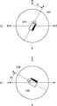
- FIG. 4A illustrates the azimuth angle ⁇ of the camera 200
- FIG. 4B illustrates the elevation angle ⁇ of the camera 200
- FIG. 4A is a top view of the camera 200.
- the camera 200 faces a direction 220 that is shifted from true north to east by an azimuth angle ⁇ at the initial shooting position, and this direction corresponds to a pan angle of 0 °.
- the azimuth angle of the pan angle reference direction 220 is ⁇ .
- the subject is panorama shot while changing the pan angle in a range of ⁇ 180 ° to + 180 ° with respect to the reference direction 220 of the azimuth angle ⁇ .
- FIG. 4B is a side view of the camera 200, and the elevation angle ⁇ is defined as positive when the camera 200 is rotated about the X axis, ie, the upward direction with respect to the 0 ° tilt direction, that is, the Y axis direction. It is an angle to do.
- the elevation angle ⁇ 0 °.
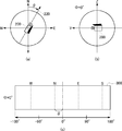
- 5 (a) to 5 (c) are diagrams for explaining panoramic images taken when the initial position of the camera 200 is in the direction of the azimuth angle ⁇ .
- FIG. 5C shows a panoramic image 300 shot in this way.
- the center of the panorama image 300 has a pan angle of 0 °
- the left half of the panorama image 300 is an image taken by changing the pan angle from 0 ° to ⁇ 180 °
- the right half has a pan angle of 0 ° to 180 °. It is an image that was taken by changing up to.
- the center position of pan angle 0 ° of panorama image 300 is shifted east from true north by azimuth angle ⁇ , the positions of north (N), south (S), east (E), and west (W) are dotted lines. It becomes the part shown by.
- the pixel positions of north (N), south (S), east (E), and west (W) are In consideration of the deviation of the azimuth angle ⁇ , it can be obtained by calculation.
- the coordinate values of the pixel positions of north (N), south (S), east (E), and west (W) may be already used as information regarding the shooting direction.
- the camera 200 In order to obtain a panoramic image of the whole celestial sphere, it is necessary to shoot by changing the elevation angle of the camera 200. For example, assuming that the angle of view of the camera 200 is 60 °, in principle, the camera 200 is tilted ⁇ 60 ° up and down, and the same shooting is performed while changing the pan angle in the range of ⁇ 180 ° to 180 °. The panoramic image of the whole celestial sphere can be obtained.
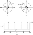
- 6 (a) to 6 (c) are diagrams for explaining panoramic images taken when the elevation angle ⁇ of the camera 200 is 60 °.
- a panoramic image 302 is taken.
- a method of photographing the vicinity of the boundary is often employed.
- the omnidirectional panoramic image obtained in this way is provided with azimuth and elevation information, and the azimuth and elevation can be specified for any pixel of the panoramic image based on the information.
- latitude / longitude information measured by GPS is given to the panoramic image as position information of the shooting location.
- the additional information to be added to the panorama image may be recorded in accordance with an image file standard called Exif (Exchangeable Image File Format) as an example.
- the place name of the shooting location can be recorded as a part of the file name, and the shooting date and time, the latitude / longitude of the shooting location, the altitude, the azimuth angle, and the like can be recorded as data in Exif format.
- the elevation angle is not defined in the Exif format, but is recorded as extended data.
- FIGS. 7A and 7B are diagrams illustrating a method of creating a panoramic image by connecting a plurality of images.
- seven images 341 to 347 taken while tilting (or panning) the camera 200 are mapped onto a cylinder, and then joined together to create a cylindrical image 340.
- the images overlap the borders of the images.
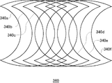
- FIG. 7B a plurality of cylindrical images shown in FIG. 7A are obtained in the pan (or tilt) direction by panning (or tilting) the camera 200 and photographing.
- an omnidirectional panoramic image 360 is finally obtained.
- FIGS. 8A to 8E are diagrams for explaining an alignment method by color difference correction when a plurality of images are connected.
- FIG. 9A to 9C are diagrams for explaining correction of lens distortion.
- the captured image generally has barrel distortion as shown in FIG. 9A and pincushion distortion as shown in FIG. 9B. Therefore, when creating a panoramic image, optical distortion is corrected as shown in FIG. Since the marker is associated with the panoramic image whose distortion has been corrected, the direction indicated by the marker and the shooting direction indicated by the position on the panoramic image to which the marker is associated almost exactly match each other. Little affected.
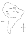
- FIG. 10 is a diagram illustrating a panoramic image displayed as a symbol at a shooting location on a two-dimensional map.
- the map generation unit 20 When there are panoramic images taken at points A, B, and C in South America, the map generation unit 20 combines the symbols 400a, 400b, and 400c of the panoramic image with the points A, B, and C on the map in South America.
- a map image is generated. This symbol is a thumbnail image or icon of a panoramic image. The scale of the displayed map can be changed. The user selects a panoramic image taken at a desired point while browsing the map.
- the map generation unit 20 may display the earth three-dimensionally and display a panoramic image as a symbol at a point on the surface of the earth.
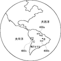
- FIG. 11 is a diagram illustrating a panoramic image displayed as a symbol at a shooting location on the surface of the earth displayed in three dimensions.
- panoramic image symbols 400a, 400b, and 400c are synthesized in three dimensions at points A, B, and C in South America.
- the user selects a panoramic image taken at a desired point while rotating the earth.
- the map is enlarged.
- FIG. 12 is a diagram for explaining a panoramic image associated with a marker.
- a panoramic image 300 at the shooting point A in FIG. 10 or FIG. 11 will be described as an example.
- the panorama image 300 at the shooting point A is associated with markers 310 and 312 for indicating that there is a panoramic image at the shooting point B in the southeast direction and that there is a panoramic image at the shooting point C in the southwest direction.
- the marker 310 corresponding to the shooting point B is associated with the pixel position in the southeast direction of the panoramic image 300
- the marker 312 corresponding to the shooting point C is associated with the pixel position in the southwest direction of the panoramic image 300. Since the shooting point B is closer to the shooting point A than the shooting point C, the marker 310 corresponding to the shooting point B is also highlighted and displayed by the marker 312 corresponding to the shooting point C. For example, the marker size is increased or the marker color is increased.
- FIG. 13 is a diagram schematically illustrating a state in which the panoramic image 300 associated with the marker of FIG. 12 is displayed in a three-dimensional manner.
- the panorama image 300 at the shooting point A is texture-mapped in a three-dimensional panorama space such as a spherical surface or a cylindrical surface, and a three-dimensional image when the three-dimensional panorama space is viewed from the viewpoint 500 in the viewing direction 510 is displayed on the screen.
- the marker 310 of the photographing point B associated on the panoramic image 300 is in the eye
- the marker 312 at the photographing point C is in the eye.
- FIG. 13 it is assumed that the user selects the marker 310 of the shooting point B.
- the panoramic image 320 of the shooting point B is displayed instead of the panoramic image 300 of the shooting point A that has been displayed so far.
- FIG. 14 is a diagram for explaining a panoramic image 320 of the shooting point B that is three-dimensionally displayed when the marker 310 of the shooting point B is selected. Similarly, a marker indicating that there is a panoramic image at another shooting point is associated with the panorama image 320 at the shooting point B. Here, a marker 312 at the shooting point C is displayed.
- the user's line-of-sight direction 510 may be set to the direction from the photographing point A to the photographing point B, that is, the southeast direction. Thereby, the user can have a sense of warping to the shooting point B while looking at the direction from the shooting point A to the shooting point B.
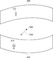
- FIG. 15 is a diagram for explaining another setting example of the line-of-sight direction 510 when the viewpoint 500 moves from the shooting point A to the shooting point B.
- FIG. 15 when the panorama image 300 at the shooting point A is switched to the panoramic image 320 at the shooting point B, the user's line-of-sight direction 510 is set to the direction of looking back from the shooting point B to the shooting point A, that is, the northwest direction.
- the viewpoint 500 moves to the shooting point B, the user sees the rear panorama image 322 instead of the front panorama image 320.
- a marker 314 corresponding to the shooting point A is associated with a position in the northwest direction, and when the user moves to the shooting point B, the marker 314 at the shooting point A that was immediately before is moved to the front. You will see.
- the user warps from the shooting point A to the shooting point B the user can feel as if looking back at the shooting point A.
- the marker 314 at the shooting point A is displayed immediately before the marker 314 at the shooting point A. To switch to the panoramic image 300 at the shooting point A.
- the panoramic image of the moving destination shooting point is not an omnidirectional image, but only a part of the pan angle range is shot.
- the destination line-of-sight direction 510 is set to the direction in which the destination is viewed or the direction in which the destination is looked back as described above, there may be no captured image in that direction in the destination panorama image. Will be displayed.
- the initial line-of-sight direction 510 in the destination panorama image may be set to a direction with a pan angle of 0 ° of the destination panorama image.
- the line-of-sight direction 510 in the destination panorama image may be determined in advance as a desired direction. The desired direction may be determined by the user, or may be automatically set on the system side, for example, as a viewing direction recommended in the panoramic image.
- the panoramic image display device of the present embodiment when a plurality of panoramic images having different shooting locations are given, there are shooting locations of other panoramic images in the shooting direction of a certain panoramic image.
- a panoramic image is associated so that it can be visually confirmed. This makes it possible to switch and display panoramic images as if warping from one shooting location to another.
- a panoramic image preview may be displayed on a screen that displays a symbol of a panoramic image at a shooting point on a map.
- a part of the panoramic image is displayed in the form of a thumbnail image, and the panoramic image can be browsed by gradually changing the pan angle and the tilt angle in the thumbnail image frame.
- the direction of the pan angle direction on the map may be displayed with an arrow or the like.
- the panoramic image associated with the marker is mapped to a three-dimensional panoramic space such as a spherical surface, and the three-dimensional panoramic image when the three-dimensional panoramic space is viewed from the designated viewing direction is displayed on the screen.
- the panoramic image associated with the marker may be simply two-dimensionally displayed. In this case, the configuration of the mapping processing unit 14 and the three-dimensional image generation unit 16 is unnecessary, and the panoramic image display device 100 can be simplified. Even in this case, when the user selects the marker of the panoramic image displayed in two dimensions, the panoramic image corresponding to the marker is switched and displayed.
- the panoramic image is not limited to the one taken with the omnidirectional photographing system as shown in FIG. 3, but is composed of an image photographed using a fisheye lens or a plurality of images photographed with a normal digital camera while changing the photographing direction. It may be an image.
- the marker setting unit 12 maps the panorama image before combining the markers to the three-dimensional panorama space, and then maps the marker to the three-dimensional panorama space so that the marker is superimposed on the three-dimensional panorama image. Displayed.
- the mapping processing unit 14 synthesizes the marker with the panoramic image to be displayed, and then the mapping processing unit 14 textures the panoramic image with the marker synthesized in the three-dimensional panoramic space. You may make it map. In any case, as long as the position where the marker should be displayed is associated with the panorama image to be displayed, it is possible to synthesize the marker with the panorama image to be displayed at any stage.
- the shooting point B is in a different country
- the display mode of the marker at the shooting point B may be changed. For example, when displaying a panoramic image taken in a country different from the shooting country of the displayed panoramic image with a marker, the shape of the marker is represented by the national flag of the country of the shooting point.
- the marker of the shooting point B may be displayed at the bottom of the panoramic image of the shooting point A.
- It can be used for an apparatus and a method for displaying a panoramic image.
Landscapes
- Engineering & Computer Science (AREA)
- Multimedia (AREA)
- Signal Processing (AREA)
- Physics & Mathematics (AREA)
- General Physics & Mathematics (AREA)
- Theoretical Computer Science (AREA)
- Processing Or Creating Images (AREA)
- User Interface Of Digital Computer (AREA)
- Image Processing (AREA)
- Digital Computer Display Output (AREA)
- Image Generation (AREA)
- Studio Devices (AREA)
Priority Applications (4)
| Application Number | Priority Date | Filing Date | Title |
|---|---|---|---|
| CN201080037432.XA CN102483859B (zh) | 2009-09-29 | 2010-05-19 | 全景图像显示装置和全景图像显示方法 |
| EP10820031.2A EP2485191A4 (en) | 2009-09-29 | 2010-05-19 | PANORAMIC DISPLAY APPARATUS AND PANORAMIC PICTURE DISPLAY METHOD |
| US13/392,002 US9251561B2 (en) | 2009-09-29 | 2010-05-19 | Apparatus and method for displaying panoramic images |
| US14/966,726 US10298839B2 (en) | 2009-09-29 | 2015-12-11 | Image processing apparatus, image processing method, and image communication system |
Applications Claiming Priority (2)
| Application Number | Priority Date | Filing Date | Title |
|---|---|---|---|
| JP2009-225305 | 2009-09-29 | ||
| JP2009225305A JP5464955B2 (ja) | 2009-09-29 | 2009-09-29 | パノラマ画像表示装置 |
Related Child Applications (2)
| Application Number | Title | Priority Date | Filing Date |
|---|---|---|---|
| US13/392,002 A-371-Of-International US9251561B2 (en) | 2009-09-29 | 2010-05-19 | Apparatus and method for displaying panoramic images |
| US14/966,726 Continuation US10298839B2 (en) | 2009-09-29 | 2015-12-11 | Image processing apparatus, image processing method, and image communication system |
Publications (1)
| Publication Number | Publication Date |
|---|---|
| WO2011039904A1 true WO2011039904A1 (ja) | 2011-04-07 |
Family
ID=43825758
Family Applications (1)
| Application Number | Title | Priority Date | Filing Date |
|---|---|---|---|
| PCT/JP2010/003362 Ceased WO2011039904A1 (ja) | 2009-09-29 | 2010-05-19 | パノラマ画像表示装置およびパノラマ画像表示方法 |
Country Status (5)
| Country | Link |
|---|---|
| US (2) | US9251561B2 (https=) |
| EP (1) | EP2485191A4 (https=) |
| JP (1) | JP5464955B2 (https=) |
| CN (1) | CN102483859B (https=) |
| WO (1) | WO2011039904A1 (https=) |
Cited By (4)
| Publication number | Priority date | Publication date | Assignee | Title |
|---|---|---|---|---|
| US9247133B2 (en) | 2011-06-01 | 2016-01-26 | Apple Inc. | Image registration using sliding registration windows |
| US9762794B2 (en) | 2011-05-17 | 2017-09-12 | Apple Inc. | Positional sensor-assisted perspective correction for panoramic photography |
| US9832378B2 (en) | 2013-06-06 | 2017-11-28 | Apple Inc. | Exposure mapping and dynamic thresholding for blending of multiple images using floating exposure |
| US10306140B2 (en) | 2012-06-06 | 2019-05-28 | Apple Inc. | Motion adaptive image slice selection |
Families Citing this family (65)
| Publication number | Priority date | Publication date | Assignee | Title |
|---|---|---|---|---|
| US9843743B2 (en) | 2009-06-03 | 2017-12-12 | Flir Systems, Inc. | Infant monitoring systems and methods using thermal imaging |
| JP5406813B2 (ja) * | 2010-10-05 | 2014-02-05 | 株式会社ソニー・コンピュータエンタテインメント | パノラマ画像表示装置およびパノラマ画像表示方法 |
| US8836714B2 (en) * | 2010-10-29 | 2014-09-16 | The University Of Utah Research Foundation | Rapid, interactive editing of massive imagery data |
| WO2013069050A1 (ja) | 2011-11-07 | 2013-05-16 | 株式会社ソニー・コンピュータエンタテインメント | 画像生成装置および画像生成方法 |
| US10284776B2 (en) | 2011-11-07 | 2019-05-07 | Sony Interactive Entertainment Inc. | Image generation apparatus and image generation method |
| JP5865388B2 (ja) | 2011-11-07 | 2016-02-17 | 株式会社ソニー・コンピュータエンタテインメント | 画像生成装置および画像生成方法 |
| CN103907341B (zh) | 2011-11-07 | 2017-05-24 | 索尼电脑娱乐公司 | 图像生成装置和图像生成方法 |
| JP5337905B2 (ja) * | 2011-12-26 | 2013-11-06 | 公益財団法人日本交通管理技術協会 | 速度計測システム、速度計測方法及びプログラム |
| JP6186775B2 (ja) | 2012-05-31 | 2017-08-30 | 株式会社リコー | 通信端末、表示方法、及びプログラム |
| CN104365081B (zh) | 2012-06-11 | 2018-05-08 | 索尼电脑娱乐公司 | 图像生成设备以及图像生成方法 |
| EP2860963B1 (en) | 2012-06-11 | 2019-05-22 | Sony Interactive Entertainment Inc. | Image generation device, and image generation method |
| CN104335569B (zh) | 2012-06-11 | 2017-08-25 | 索尼电脑娱乐公司 | 图像生成设备以及图像生成方法 |
| US9488489B2 (en) | 2012-09-28 | 2016-11-08 | Google Inc. | Personalized mapping with photo tours |
| JP6044328B2 (ja) * | 2012-12-26 | 2016-12-14 | 株式会社リコー | 画像処理システム、画像処理方法およびプログラム |
| KR20140100656A (ko) * | 2013-02-06 | 2014-08-18 | 한국전자통신연구원 | 전방향 영상 및 3차원 데이터를 이용한 시점 영상 제공 장치 및 방법 |
| CN104063796B (zh) * | 2013-03-19 | 2022-03-25 | 腾讯科技(深圳)有限公司 | 对象信息展示方法、系统及装置 |
| US9398215B2 (en) * | 2013-04-16 | 2016-07-19 | Eth Zurich | Stereoscopic panoramas |
| CN105144687B (zh) | 2013-04-30 | 2019-07-26 | 索尼公司 | 图像处理装置、图像处理方法及计算机可读介质 |
| JP6228392B2 (ja) | 2013-05-31 | 2017-11-08 | 任天堂株式会社 | パノラマ画像表示プログラム、パノラマ画像表示装置、パノラマ画像表示システム、および、パノラマ画像表示方法 |
| JP6167703B2 (ja) | 2013-07-08 | 2017-07-26 | 株式会社リコー | 表示制御装置、プログラム及び記録媒体 |
| US9244940B1 (en) * | 2013-09-27 | 2016-01-26 | Google Inc. | Navigation paths for panorama |
| US9973692B2 (en) | 2013-10-03 | 2018-05-15 | Flir Systems, Inc. | Situational awareness by compressed display of panoramic views |
| CN103747230A (zh) * | 2013-12-11 | 2014-04-23 | 深圳先进技术研究院 | 动态定位视频电子地图投影系统和方法 |
| JP2015125002A (ja) * | 2013-12-25 | 2015-07-06 | 株式会社ズームスケープ | 計測用画像撮影方法及び画像計測プログラム |
| JP5835384B2 (ja) * | 2014-03-18 | 2015-12-24 | 株式会社リコー | 情報処理方法、情報処理装置、およびプログラム |
| JP5835383B2 (ja) * | 2014-03-18 | 2015-12-24 | 株式会社リコー | 情報処理方法、情報処理装置、およびプログラム |
| US9189839B1 (en) | 2014-04-24 | 2015-11-17 | Google Inc. | Automatically generating panorama tours |
| US9002647B1 (en) | 2014-06-27 | 2015-04-07 | Google Inc. | Generating turn-by-turn direction previews |
| US9418472B2 (en) | 2014-07-17 | 2016-08-16 | Google Inc. | Blending between street view and earth view |
| CN105635651B (zh) * | 2014-10-29 | 2019-05-24 | 浙江大华技术股份有限公司 | 一种球机定位方法及装置 |
| JP6358339B2 (ja) * | 2014-12-08 | 2018-07-18 | 株式会社リコー | 画像管理システム、及び画像管理方法 |
| US10178325B2 (en) | 2015-01-19 | 2019-01-08 | Oy Vulcan Vision Corporation | Method and system for managing video of camera setup having multiple cameras |
| JP5987931B2 (ja) | 2015-02-09 | 2016-09-07 | 株式会社リコー | 映像表示システム、情報処理装置、映像表示方法、映像表示プログラム、映像処理装置、映像処理方法および映像処理プログラム |
| US9813621B2 (en) | 2015-05-26 | 2017-11-07 | Google Llc | Omnistereo capture for mobile devices |
| US9609176B2 (en) * | 2015-08-27 | 2017-03-28 | Nokia Technologies Oy | Method and apparatus for modifying a multi-frame image based upon anchor frames |
| CN106548516B (zh) * | 2015-09-23 | 2021-05-14 | 清华大学 | 三维漫游方法和装置 |
| CN109074629A (zh) * | 2015-10-29 | 2018-12-21 | Oy沃肯视觉有限公司 | 使用联网照相机对关注的区域进行视频摄像 |
| CN105898272A (zh) * | 2015-12-28 | 2016-08-24 | 乐视致新电子科技(天津)有限公司 | 360度图像加载方法、加载模块及移动终端 |
| CN105491353B (zh) * | 2016-01-15 | 2018-12-18 | 广东小天才科技有限公司 | 一种远程监控方法和装置 |
| CN107333051B (zh) * | 2016-04-28 | 2019-06-21 | 杭州海康威视数字技术股份有限公司 | 一种室内全景视频生成方法及装置 |
| CN115118952B (zh) * | 2016-05-13 | 2024-07-19 | 索尼公司 | 信息处理装置和信息处理方法以及再现装置和再现方法 |
| CN106296589B (zh) * | 2016-08-26 | 2020-12-04 | 北京疯景科技有限公司 | 全景图像的处理方法及装置 |
| CN106485772B (zh) * | 2016-09-30 | 2019-10-15 | 北京百度网讯科技有限公司 | 全景切换方法及系统 |
| TWI619093B (zh) * | 2016-10-19 | 2018-03-21 | 財團法人資訊工業策進會 | 視覺定位裝置、方法及其電腦程式產品 |
| CN106604102B (zh) * | 2016-11-29 | 2019-06-28 | 广州华多网络科技有限公司 | 直播记录图片展示方法及装置 |
| US10614606B2 (en) * | 2016-11-30 | 2020-04-07 | Ricoh Company, Ltd. | Information processing apparatus for creating an animation from a spherical image |
| CN106780602B (zh) * | 2016-12-05 | 2019-09-17 | 浙江华睿科技有限公司 | 一种枪球定位方法及装置 |
| US10419669B2 (en) | 2017-01-17 | 2019-09-17 | Disney Enterprises, Inc. | Omnistereoscopic panoramic video |
| KR101810671B1 (ko) | 2017-03-07 | 2018-01-25 | 링크플로우 주식회사 | 전방향 영상의 방향 정보를 생성하는 방법 및 이러한 방법을 수행하는 장치 |
| JP6840842B2 (ja) * | 2017-05-24 | 2021-03-10 | 古野電気株式会社 | 映像生成装置 |
| CN107689030A (zh) * | 2017-09-18 | 2018-02-13 | 上海联影医疗科技有限公司 | 一种图像处理的方法及装置 |
| CN107608605A (zh) * | 2017-09-28 | 2018-01-19 | 北京金山安全软件有限公司 | 一种图像的显示方法、装置、电子设备及存储介质 |
| US10713811B2 (en) * | 2017-09-29 | 2020-07-14 | Sensormatic Electronics, LLC | Security camera system with multi-directional mount and method of operation |
| KR102076139B1 (ko) * | 2017-09-29 | 2020-02-11 | 에스케이 텔레콤주식회사 | 360 영상 라이브 스트리밍 서비스 방법 및 서버장치 |
| JP7085865B2 (ja) * | 2018-03-09 | 2022-06-17 | キヤノン株式会社 | 画像処理装置、画像処理方法 |
| JP6718928B2 (ja) * | 2018-07-31 | 2020-07-08 | 株式会社コロプラ | 映像出力システム |
| EP3877865A4 (en) | 2018-12-28 | 2021-11-24 | Zhejiang Dahua Technology Co., Ltd. | SYSTEMS AND METHODS FOR IMAGE DISPLAY |
| JP7373294B2 (ja) * | 2019-04-12 | 2023-11-02 | 株式会社ソニー・インタラクティブエンタテインメント | 画像処理装置、画像提供サーバ、画像表示方法、および画像提供方法 |
| JP7597310B2 (ja) * | 2019-07-19 | 2024-12-10 | 富士フイルム株式会社 | 画像表示装置、方法及びプログラム |
| CN110740263B (zh) * | 2019-10-31 | 2021-03-12 | 维沃移动通信有限公司 | 一种图像处理方法和终端设备 |
| CN113052753B (zh) * | 2019-12-26 | 2024-06-07 | 百度在线网络技术(北京)有限公司 | 全景拓扑结构的生成方法、装置、设备及可读存储介质 |
| CN111107323B (zh) * | 2019-12-30 | 2021-06-04 | 徐书诚 | 一种实现全景影像单屏环视窗显示计算机系统 |
| CN111586426B (zh) * | 2020-04-30 | 2022-08-09 | 广州方硅信息技术有限公司 | 全景直播的信息展示方法、装置、设备及存储介质 |
| CN111667591B (zh) * | 2020-06-15 | 2024-02-27 | 常州市规划设计院 | 基于全景摄影的虚拟现实融合方法 |
| JP7710386B2 (ja) * | 2022-02-18 | 2025-07-18 | 株式会社ソニー・インタラクティブエンタテインメント | 情報処理装置、デバイス速度推定方法およびデバイス位置推定方法 |
Citations (2)
| Publication number | Priority date | Publication date | Assignee | Title |
|---|---|---|---|---|
| JP2001229397A (ja) * | 2000-02-17 | 2001-08-24 | Ricoh Co Ltd | 3次元仮想空間構築方法及びシステム並びに記憶媒体 |
| JP2005327314A (ja) * | 2005-07-11 | 2005-11-24 | Fujitsu Ltd | 画像表示方法および装置 |
Family Cites Families (18)
| Publication number | Priority date | Publication date | Assignee | Title |
|---|---|---|---|---|
| JP3910794B2 (ja) * | 2000-11-14 | 2007-04-25 | 株式会社エヌ・ティ・ティ・ドコモ | 映像検索ファイル作成方法およびホームページ更新方法 |
| JP2004325459A (ja) * | 2004-05-31 | 2004-11-18 | Toshiba Corp | 位置情報表示装置、位置情報管理システムおよび位置情報管理方法 |
| JP4853149B2 (ja) | 2005-09-14 | 2012-01-11 | ソニー株式会社 | 画像処理装置、画像表示装置、画像処理方法、プログラムおよび記録媒体 |
| US20080079808A1 (en) * | 2006-09-29 | 2008-04-03 | Jeffrey Michael Ashlock | Method and device for collection and application of photographic images related to geographic location |
| WO2008044607A1 (en) * | 2006-10-04 | 2008-04-17 | Nikon Corporation | Electronic camera |
| US9361943B2 (en) * | 2006-11-07 | 2016-06-07 | The Board Of Trustees Of The Leland Stanford Jr. University | System and method for tagging objects in a panoramic video and associating functions and indexing panoramic images with same |
| CN101743569A (zh) * | 2007-05-25 | 2010-06-16 | 谷歌公司 | 渲染、查看和注释全景图像及其应用 |
| US7990394B2 (en) * | 2007-05-25 | 2011-08-02 | Google Inc. | Viewing and navigating within panoramic images, and applications thereof |
| US8487957B1 (en) * | 2007-05-29 | 2013-07-16 | Google Inc. | Displaying and navigating within photo placemarks in a geographic information system, and applications thereof |
| US8009178B2 (en) * | 2007-06-29 | 2011-08-30 | Microsoft Corporation | Augmenting images for panoramic display |
| JP2009093294A (ja) | 2007-10-04 | 2009-04-30 | Victor Co Of Japan Ltd | 画像情報管理システムおよび画像登録閲覧装置 |
| US20100004566A1 (en) * | 2008-01-11 | 2010-01-07 | Esoles, L,L.C. | Intelligent orthotic insoles |
| US8174561B2 (en) | 2008-03-14 | 2012-05-08 | Sony Ericsson Mobile Communications Ab | Device, method and program for creating and displaying composite images generated from images related by capture position |
| CN102187694A (zh) * | 2008-05-28 | 2011-09-14 | 谷歌公司 | 在移动计算设备上的运动控制的视图 |
| US9310992B2 (en) * | 2008-08-22 | 2016-04-12 | Google Inc. | Panning in a three dimensional environment on a mobile device |
| US8493408B2 (en) * | 2008-11-19 | 2013-07-23 | Apple Inc. | Techniques for manipulating panoramas |
| US20110099507A1 (en) * | 2009-10-28 | 2011-04-28 | Google Inc. | Displaying a collection of interactive elements that trigger actions directed to an item |
| JP5701967B2 (ja) | 2013-12-16 | 2015-04-15 | 株式会社ソニー・コンピュータエンタテインメント | 画像表示装置および画像表示方法 |
-
2009
- 2009-09-29 JP JP2009225305A patent/JP5464955B2/ja active Active
-
2010
- 2010-05-19 CN CN201080037432.XA patent/CN102483859B/zh active Active
- 2010-05-19 US US13/392,002 patent/US9251561B2/en active Active
- 2010-05-19 WO PCT/JP2010/003362 patent/WO2011039904A1/ja not_active Ceased
- 2010-05-19 EP EP10820031.2A patent/EP2485191A4/en not_active Ceased
-
2015
- 2015-12-11 US US14/966,726 patent/US10298839B2/en active Active
Patent Citations (2)
| Publication number | Priority date | Publication date | Assignee | Title |
|---|---|---|---|---|
| JP2001229397A (ja) * | 2000-02-17 | 2001-08-24 | Ricoh Co Ltd | 3次元仮想空間構築方法及びシステム並びに記憶媒体 |
| JP2005327314A (ja) * | 2005-07-11 | 2005-11-24 | Fujitsu Ltd | 画像表示方法および装置 |
Non-Patent Citations (2)
| Title |
|---|
| See also references of EP2485191A4 * |
| SHUN IKEDA ET AL.: "Panorama Gazo o Mochiita Kaso Kukan Kochiku", DEWS2006 RONBUNSHU, 30 June 2006 (2006-06-30), XP008150362, Retrieved from the Internet <URL:http://www.ieice.org/iss/de/DEWS/DEWS2006/doc/4B-il2.pdf> [retrieved on 20100609] * |
Cited By (4)
| Publication number | Priority date | Publication date | Assignee | Title |
|---|---|---|---|---|
| US9762794B2 (en) | 2011-05-17 | 2017-09-12 | Apple Inc. | Positional sensor-assisted perspective correction for panoramic photography |
| US9247133B2 (en) | 2011-06-01 | 2016-01-26 | Apple Inc. | Image registration using sliding registration windows |
| US10306140B2 (en) | 2012-06-06 | 2019-05-28 | Apple Inc. | Motion adaptive image slice selection |
| US9832378B2 (en) | 2013-06-06 | 2017-11-28 | Apple Inc. | Exposure mapping and dynamic thresholding for blending of multiple images using floating exposure |
Also Published As
| Publication number | Publication date |
|---|---|
| JP5464955B2 (ja) | 2014-04-09 |
| EP2485191A1 (en) | 2012-08-08 |
| CN102483859A (zh) | 2012-05-30 |
| US20120200665A1 (en) | 2012-08-09 |
| EP2485191A4 (en) | 2016-03-09 |
| CN102483859B (zh) | 2015-04-01 |
| JP2011076249A (ja) | 2011-04-14 |
| US10298839B2 (en) | 2019-05-21 |
| US20160100104A1 (en) | 2016-04-07 |
| US9251561B2 (en) | 2016-02-02 |
Similar Documents
| Publication | Publication Date | Title |
|---|---|---|
| JP5464955B2 (ja) | パノラマ画像表示装置 | |
| JP5406813B2 (ja) | パノラマ画像表示装置およびパノラマ画像表示方法 | |
| JP5409577B2 (ja) | パノラマ画像生成装置およびパノラマ画像生成方法 | |
| JP5250598B2 (ja) | 画像表示装置および画像表示方法 | |
| EP4298599A1 (en) | Image processing method, recording medium, image processing apparatus, and image processing system | |
| JP6816465B2 (ja) | 画像表示システム、通信システム、画像表示方法、及びプログラム | |
| JP2019145059A (ja) | 情報処理装置、情報処理システム、情報処理方法及びプログラム | |
| JP2017212510A (ja) | 画像管理装置、プログラム、画像管理システム及び情報端末 | |
| JP5701967B2 (ja) | 画像表示装置および画像表示方法 | |
| JP7447403B2 (ja) | 情報処理装置、情報処理システム、情報処理方法及びプログラム | |
| JP6122991B2 (ja) | 画像表示装置および画像表示方法 | |
| JP5920857B2 (ja) | 画像表示装置および画像表示方法 | |
| JP2024017224A (ja) | 情報処理装置、入出力装置、情報処理システム、情報処理方法、入出力方法、およびプログラム | |
| JP5646033B2 (ja) | 画像表示装置および画像表示方法 | |
| JP2021125225A (ja) | 画像表示装置、画像表示方法及びプログラム | |
| JP2019140459A (ja) | 表示情報作成装置、情報処理装置、撮影システムおよびプログラム | |
| JP2017182548A (ja) | 画像管理システム、画像管理方法、画像通信システム及びプログラム | |
| JP2025011441A (ja) | 電子機器、電子機器の制御方法、プログラム、および記憶媒体 | |
| JP2017182843A (ja) | プログラム、表示制御装置及び表示制御方法 |
Legal Events
| Date | Code | Title | Description |
|---|---|---|---|
| WWE | Wipo information: entry into national phase |
Ref document number: 201080037432.X Country of ref document: CN |
|
| 121 | Ep: the epo has been informed by wipo that ep was designated in this application |
Ref document number: 10820031 Country of ref document: EP Kind code of ref document: A1 |
|
| WWE | Wipo information: entry into national phase |
Ref document number: 2010820031 Country of ref document: EP |
|
| NENP | Non-entry into the national phase |
Ref country code: DE |
|
| WWE | Wipo information: entry into national phase |
Ref document number: 13392002 Country of ref document: US |