WO2011037152A1 - 無線タグ通信装置 - Google Patents
無線タグ通信装置 Download PDFInfo
- Publication number
- WO2011037152A1 WO2011037152A1 PCT/JP2010/066459 JP2010066459W WO2011037152A1 WO 2011037152 A1 WO2011037152 A1 WO 2011037152A1 JP 2010066459 W JP2010066459 W JP 2010066459W WO 2011037152 A1 WO2011037152 A1 WO 2011037152A1
- Authority
- WO
- WIPO (PCT)
- Prior art keywords
- communication
- antenna
- channels
- channel
- wireless tag
- Prior art date
- Legal status (The legal status is an assumption and is not a legal conclusion. Google has not performed a legal analysis and makes no representation as to the accuracy of the status listed.)
- Ceased
Links
Images


Classifications
-
- H—ELECTRICITY
- H01—ELECTRIC ELEMENTS
- H01Q—ANTENNAS, i.e. RADIO AERIALS
- H01Q3/00—Arrangements for changing or varying the orientation or the shape of the directional pattern of the waves radiated from an antenna or antenna system
- H01Q3/24—Arrangements for changing or varying the orientation or the shape of the directional pattern of the waves radiated from an antenna or antenna system varying the orientation by switching energy from one active radiating element to another, e.g. for beam switching
-
- G—PHYSICS
- G06—COMPUTING OR CALCULATING; COUNTING
- G06K—GRAPHICAL DATA READING; PRESENTATION OF DATA; RECORD CARRIERS; HANDLING RECORD CARRIERS
- G06K7/00—Methods or arrangements for sensing record carriers, e.g. for reading patterns
- G06K7/0008—General problems related to the reading of electronic memory record carriers, independent of its reading method, e.g. power transfer
-
- G—PHYSICS
- G06—COMPUTING OR CALCULATING; COUNTING
- G06K—GRAPHICAL DATA READING; PRESENTATION OF DATA; RECORD CARRIERS; HANDLING RECORD CARRIERS
- G06K7/00—Methods or arrangements for sensing record carriers, e.g. for reading patterns
- G06K7/10—Methods or arrangements for sensing record carriers, e.g. for reading patterns by electromagnetic radiation, e.g. optical sensing; by corpuscular radiation
- G06K7/10009—Methods or arrangements for sensing record carriers, e.g. for reading patterns by electromagnetic radiation, e.g. optical sensing; by corpuscular radiation sensing by radiation using wavelengths larger than 0.1 mm, e.g. radio-waves or microwaves
- G06K7/10019—Methods or arrangements for sensing record carriers, e.g. for reading patterns by electromagnetic radiation, e.g. optical sensing; by corpuscular radiation sensing by radiation using wavelengths larger than 0.1 mm, e.g. radio-waves or microwaves resolving collision on the communication channels between simultaneously or concurrently interrogated record carriers.
- G06K7/10069—Methods or arrangements for sensing record carriers, e.g. for reading patterns by electromagnetic radiation, e.g. optical sensing; by corpuscular radiation sensing by radiation using wavelengths larger than 0.1 mm, e.g. radio-waves or microwaves resolving collision on the communication channels between simultaneously or concurrently interrogated record carriers. the collision being resolved in the frequency domain, e.g. by hopping from one frequency to the other
-
- G—PHYSICS
- G06—COMPUTING OR CALCULATING; COUNTING
- G06K—GRAPHICAL DATA READING; PRESENTATION OF DATA; RECORD CARRIERS; HANDLING RECORD CARRIERS
- G06K7/00—Methods or arrangements for sensing record carriers, e.g. for reading patterns
- G06K7/10—Methods or arrangements for sensing record carriers, e.g. for reading patterns by electromagnetic radiation, e.g. optical sensing; by corpuscular radiation
- G06K7/10009—Methods or arrangements for sensing record carriers, e.g. for reading patterns by electromagnetic radiation, e.g. optical sensing; by corpuscular radiation sensing by radiation using wavelengths larger than 0.1 mm, e.g. radio-waves or microwaves
- G06K7/10316—Methods or arrangements for sensing record carriers, e.g. for reading patterns by electromagnetic radiation, e.g. optical sensing; by corpuscular radiation sensing by radiation using wavelengths larger than 0.1 mm, e.g. radio-waves or microwaves using at least one antenna particularly designed for interrogating the wireless record carriers
- G06K7/10356—Methods or arrangements for sensing record carriers, e.g. for reading patterns by electromagnetic radiation, e.g. optical sensing; by corpuscular radiation sensing by radiation using wavelengths larger than 0.1 mm, e.g. radio-waves or microwaves using at least one antenna particularly designed for interrogating the wireless record carriers using a plurality of antennas, e.g. configurations including means to resolve interference between the plurality of antennas
Definitions
- the present invention relates to a technology for suppressing interference on the wireless tag side and mutual interference of the wireless tag communication device.
- Wireless tag communication devices that perform wireless communication with wireless tags are already known.
- As a conventional technique for suppressing interference when a plurality of wireless tag communication apparatuses perform communication for example, there is a wireless tag communication system described in Patent Document 1.
- the RFID tag communication apparatus provided in the conventional RFID tag communication system determines the level of the received interference signal, and determines the channel and polarization direction in which the interference signal level is equal to or less than the threshold value. Then, the wireless tag communication device executes communication with the wireless tag using the determined channel and polarization direction. As a result, when one RFID tag communication device tries to start communication, the possibility of detecting an empty channel not used by another RFID tag communication device is increased, and interference between a plurality of RFID tag communication devices is suppressed. To do.
- An object of the present invention is to provide a wireless tag communication device capable of suppressing interference on the wireless tag side and interference between a plurality of wireless tag communication devices and improving the reliability of wireless communication between the wireless tag communication device and the wireless tag. There is.
- antenna means for performing wireless communication with a wireless tag within a predetermined frequency range including a plurality of channels, and signal strength of a signal received by the antenna means.
- the detection means for detecting, the first determination means for determining the usage status for all of the plurality of channels based on the signal intensity detected by the detection means, and the plurality of channels used by the first determination means.
- Determining means for determining a different communication operation between the case where it is determined that the channel is not used and the case where it is determined that any one of the plurality of channels is used, and the use which is determined by the first determining means
- channel selection means for selecting a channel to be used among the plurality of channels, and the channel selection means With-option has been said channel, said by the antenna means, and having a first control means for controlling such a communication operation in which the decision means decides perform the wireless tag and the wireless communication.
- the first determination means determines the usage status for all of the plurality of channels based on the signal intensity detected by the detection means.
- the determining means determines the communication operation according to whether it is determined by the first determining means that all of the plurality of channels are not used, or one of the plurality of channels is determined to be used. . Then, using the selected channel, the first control unit performs wireless communication with the wireless tag by the communication operation determined by the determination unit.
- the wireless communication is executed or at least some of the channels are used. In this state, it is possible to reduce the transmission output and execute communication. Thereby, it is possible to suppress the occurrence of interference on the wireless tag side having no frequency selection function. As a result, the reliability of communication can be improved as compared with the conventional technique in which an unused channel is confirmed among a plurality of channels and wireless communication is performed using the channel. Therefore, the reliability of wireless communication can be improved as a whole communication system including a plurality of wireless tag communication devices.
- the determining means determines to perform communication by the first control means when the first determining means determines that all of the plurality of channels are not used. It is characterized by doing.
- the determination unit when the determination unit determines that any one of the plurality of channels is being used by the first determination unit, the determination unit is configured based on a result of the detection unit. The transmission output of the first control means is determined.
- the second control unit performs control for prohibiting the radio communication by the antenna unit for a predetermined time, and when the radio communication by the first control unit is completed, (2) The control means prohibits wireless communication by the antenna means for a predetermined time.
- the wireless tag communication device does not perform wireless communication for a predetermined time by the second control means after wireless communication with the wireless tag is completed, it is possible to prevent other wireless tag communication devices from being unable to communicate. it can.
- the first aspect further comprises channel switching means for switching the channel used in wireless communication by the antenna means, and the first determination means is provided for each channel switched by the channel switching means. Then, it is determined whether or not the signal intensity detected by the detecting means is larger than a confirmation threshold value for confirming the use state.
- the configuration of the circuit on the receiving side can be simplified, and a general-purpose carrier sense circuit that has been conventionally used can also be diverted.
- the first determination means collectively determines whether or not the signal intensity detected by the detection means is larger than a confirmation threshold for the plurality of channels. It is characterized by.
- a seventh invention is the signal intensity detected by the detection means in the fifth or sixth invention, using a selection threshold value for selecting a channel having a value smaller than the confirmation threshold value. Further includes second determination means for determining whether or not the threshold value for selection is greater than the threshold value for selection, wherein the channel selection means includes the second determination means among the plurality of channels, and the signal strength is determined by the second determination means. A channel determined to be equal to or less than a channel selection threshold is selected as a channel to be used.
- the threshold value for selection that is normally used is often set to a relatively low value on the assumption that a plurality of RFID tag communication devices are spaced apart and interfere with each other. Assuming the occurrence of interference in the wireless tag, a stronger radio wave is required between the wireless tag communication device and the wireless tag. Is preferably used.
- the usage condition confirmation threshold value is larger than the channel selection threshold value, so that the first determination means and the second determination means are rational and effective. Judgment can be made.
- the antenna unit or the polarization plane of the antenna unit is switched.
- Antenna switching means wherein the detection means detects the signal strength received by the antenna means or the antenna means after the antenna plane is switched by the antenna switching means, and the first determination The means determines the usage status of all the plurality of channels based on the signal strength detected by the detection means after the antenna means or the polarization plane of the antenna means is switched by the antenna switching means. It is characterized by.
- the antenna switching unit switches the antenna unit or the polarization plane of the antenna unit.
- the detection means detects the signal intensity of the antenna means after the switching, and the first determination means determines the usage status of all the plurality of channels based on the detected intensity.
- a communication means for communicating with another RFID tag communication apparatus, and wireless communication with the other RFID tag communication apparatus using the communication means Transmitting means for transmitting a request signal for requesting stoppage, and receiving means for receiving a response signal responding to the communication state from the other RFID tag communication apparatus corresponding to the request signal from the transmitting means
- the first determination means determines the usage status for all of the plurality of channels based on the signal strength detected by the detection means when the reception means does not receive the response signal. It is characterized by.
- a plurality of RFID tag communication devices communicate with each other using a communication means to perform a cooperative operation.
- a cooperative operation when one RFID tag communication apparatus performs wireless communication, the other RFID tag communication apparatuses that cooperate with each other stop wireless communication. Wireless communication can be started. As a result, information transmission efficiency can be improved.
- the present invention it is possible to suppress interference between a plurality of wireless tag communication devices and interference on the wireless tag side, and improve the reliability of wireless communication.
- the wireless tag communication device 1 as a wireless tag communication device according to an embodiment of the present invention will be described.
- a large number of books B are stored in a bookcase S of a library.
- a radio tag T is affixed to the spine of each book B.
- the wireless tag T stores book information such as a book name and an author name.
- the two RFID tag communication apparatuses 1 and 1 search for the RFID tag T attached to the book B, respectively, within a predetermined range.
- the wireless tag communication device 1 transmits information to the wireless tag T existing in the area A where wireless communication is possible, and receives a response signal and the book information from the wireless tag T.
- the wireless tag communication device 1 is a portable wireless communication device and has a substantially rectangular parallelepiped housing 2a.
- the housing 2 a is provided with a reader antenna unit 3 whose polarization plane can be switched between the vertical direction and the horizontal direction, and an operation unit 7 and a display unit 8.
- the schematic configuration of the wireless tag communication device 1 will be described with reference to FIG.
- the wireless tag communication device 1 includes a main body control unit 2 provided inside the housing 2a and a reader antenna unit 3 as antenna means.
- the reader antenna unit 3 performs transmission / reception of radio waves for performing wireless communication with the wireless tag T (details will be described later) within a predetermined frequency range including a plurality of channels, for example, all bands permitted by laws and regulations.
- the reader antenna unit 3 includes a microstrip antenna 11 and a changeover switch circuit 12 for switching the polarization plane of the microstrip antenna 11.
- the main body control unit 2 includes a CPU 4, a nonvolatile storage device 5, a memory 6, the operation unit 7, the display unit 8, and an RF communication control unit 9.
- the wireless tag T has a wireless tag circuit unit To including a tag antenna 151 and an IC circuit unit 150.
- the wireless tag T is configured such that the wireless tag circuit portion To is provided on a base material (not shown) or the like and can be attached to the book B.
- the wireless tag T is affixed to each book B in a posture in which the longitudinal direction of the tag antenna 151 is oriented in either the vertical direction or the horizontal direction.
- the surface including the longitudinal direction of the tag antenna 151 that is a dipole antenna is a surface having high sensitivity to the electric field of radio waves. This plane is called the polarization plane.
- the RF communication control unit 9 accesses information including the tag ID stored in the IC circuit unit 150 of the RFID circuit unit To via the reader antenna unit 3.
- the non-volatile storage device 5 includes a hard disk device or a flash memory, and stores various information such as the management status of the book B.
- the memory 6 is composed of, for example, a RAM or a ROM.
- the operation unit 7 receives instructions or information from the user.
- the display unit 8 displays various information or messages.
- the CPU 4 performs signal processing according to a program stored in advance in the nonvolatile storage device 5 using the temporary storage function of the RAM in the memory 6 and performs various controls of the entire RFID tag communication device 1.
- the CPU 4 processes information read from the IC circuit unit 150 of the RFID tag circuit unit To and generates various commands for accessing the IC circuit unit 150 of the RFID tag circuit unit To.
- the RF communication control unit 9 includes a transmission unit 212, a reception unit 213, and a transmission / reception separator 214.
- the transmission unit 212 is a block that generates an interrogation wave for accessing the wireless tag information of the IC circuit unit 150 of the wireless tag circuit unit To via the reader antenna unit 3.
- the transmission unit 212 includes a crystal resonator 215 ⁇ / b> A, a Phase Locked Loop (PLL) 215 ⁇ / b> B, a Voltage Controlled Oscillator (VCO) 215 ⁇ / b> C, a transmission multiplication circuit 216, and a variable transmission amplifier 217.
- PLL Phase Locked Loop
- VCO Voltage Controlled Oscillator
- the crystal resonator 215A generates a reference frequency.
- the PLL 215B performs control based on a command from the CPU 4 so that the frequency of the carrier wave output from the VCO 215C becomes a predetermined frequency based on the reference frequency generated by the crystal resonator 215A.
- the VCO 215C outputs a carrier wave having a frequency determined based on the control voltage generated by the PLL 215B. For example, a UHF band, a microwave band, or a short wave band is used as the frequency of the generated carrier wave.
- the transmission multiplication circuit 216 modulates the generated carrier wave based on the signal supplied from the CPU 4.
- the transmission multiplication circuit 216 performs amplitude modulation based on the “TX_ASK” signal from the CPU 4.
- a variable amplification factor amplifier or the like may be used instead of the transmission multiplication circuit 216.
- the variable transmission amplifier 217 amplifies the modulated wave modulated by the transmission multiplication circuit 216.
- the variable transmission amplifier 217 performs amplification at an amplification factor determined by the “TX_PWR” signal from the CPU 4.
- the output of the transmission amplifier 217 is transmitted to the microstrip antenna 11 via the transmission / reception separator 214, is radiated from the microstrip antenna 11 as an interrogation wave, and is supplied to the IC circuit unit 150 of the RFID circuit unit To.
- the interrogation wave is not limited to the signal modulated as described above, that is, the modulation wave, and may be only a simple carrier wave.
- the receiving unit 213 inputs a response wave from the RFID tag circuit unit To received by the reader antenna unit 3.
- the receiving unit 213 includes a transmission / reception separator 214, a band pass filter 227, an I phase reception multiplication circuit 218, an I phase low pass filter 219, an I phase reception amplifier 221, an I phase limiter 220, and a phase shifter 227.
- RSSI Received Signal Strength Indicator
- the I-phase reception multiplication circuit 218 multiplies the response wave from the RFID tag circuit section To received by the microstrip antenna 11 and input via the transmission / reception separator 214 and the bandpass filter 227 and the generated carrier wave. Then demodulate.
- the I-phase low-pass filter 219 extracts only a necessary band signal from the output of the I-phase reception multiplication circuit 218.
- the I-phase reception amplifier 221 amplifies the output of the I-phase low-pass filter 219.
- the I-phase limiter 220 further amplifies the output of the I-phase receiving amplifier 221 and converts it into a digital signal.
- the phase shifter 227 delays the phase of the carrier wave generated as described above by 90 °.
- the Q-phase reception multiplication circuit 222 multiplies the response wave received from the RFID tag circuit unit To by the reader antenna unit 3 and the carrier wave whose phase is delayed by 90 ° by the phase shifter 227.
- the Q-phase low-pass filter 223 extracts only a necessary band signal from the output of the Q-phase reception multiplication circuit 222.
- the Q-phase reception amplifier 225 amplifies the output of the Q-phase low-pass filter 223.
- the Q-phase limiter 224 further amplifies the output of the Q-phase receiving amplifier 225 and converts it into a digital signal.
- the signal “RXS-I” output from the I-phase limiter 220 and the signal “RXS-Q” output from the Q-phase limiter 224 are input to the CPU 4 and processed.
- the outputs of the I-phase reception amplifier 221 and the Q-phase reception amplifier 225 are also input to the RSSI circuit 226, and a signal “RSSI” indicating the strength of these signals is input to the CPU 4.
- RSSI signal “RSSI” indicating the strength of these signals
- the reader antenna unit 3 includes the microstrip antenna 11 and the changeover switch circuit 12 for switching the polarization plane of the microstrip antenna 11 as described above.
- the changeover switch circuit 12 is, for example, a switch circuit using a known high-frequency FET or diode.
- the changeover switch circuit 12 selects one of two feeding points provided in the microstrip antenna 11 according to a control signal from the CPU 4 and connects it to the transmission / reception separator 214.
- the microstrip antenna 11 has two planes whose polarization planes are orthogonal to each other, for example, a vertical plane and a horizontal plane indicated by broken lines in FIGS. Switch to either.
- the feature of this embodiment is that the CPU 4 determines the usage status for all of a plurality of channels based on the received signal strength detected by the RSSI circuit 226. When it is determined that all the plurality of channels are not used, the CPU 4 selects a channel to be used from among the plurality of channels. Then, transmission / reception of information with the wireless tag T is performed using the selected channel.
- step S10 the CPU 4 executes appropriate initial antenna settings for various parameters of the reader antenna unit 3.
- the CPU 4 outputs a control signal to the changeover switch circuit 12, and the polarization plane of the microstrip antenna 11 as an antenna attribute is initially set to one of the two orthogonal planes described above.
- step S11 in which the variable CH (hereinafter, simply referred to as “channel variable CH”) representing the channel numbers included in a plurality of channels set in advance in a predetermined frequency range permitted by law, for example, is set to 1.
- a channel number TX_Ch (hereinafter simply referred to as “channel TX_Ch”) representing a channel to be used is initialized to zero.
- step S12 the CPU 4 acquires the received signal strength Vs detected by the RSSI circuit 226.
- step S13 the CPU 4 determines whether or not the received signal strength Vs acquired in step S12 is larger than a predetermined usage condition confirmation threshold value V_t1.
- This procedure functions as first determination means described in each claim.
- step S ⁇ b> 14 the CPU 4 outputs a control signal to the changeover switch circuit 12 and switches the polarization plane of the microstrip antenna 11 to a plane orthogonal to the currently used plane among the two orthogonal planes described above. .
- This procedure functions as the antenna switching means described in each claim. Instead of switching the polarization plane of the same antenna as described above, a plurality of antennas having different antenna attributes may be provided in advance, and the antenna switching unit may be switched to another antenna. Then, it returns to step S12 and repeats the same procedure.
- step S14 determines whether the received signal strength Vs is equal to or lower than the usage status confirmation threshold V_t1 in step S13. If the received signal strength Vs is equal to or lower than the usage status confirmation threshold V_t1 in step S13, the determination in step S14 is not satisfied, and the process proceeds to step S15.
- step S16 the CPU 4 determines whether or not the received signal strength Vs acquired in step S12 is smaller than the channel selection threshold value V_t2.
- the channel selection threshold value V_t2 is determined in advance so as to be smaller than the usage status confirmation threshold value V_t1. This procedure functions as the second determination means described in each claim.
- step S16 the determination in step S16 is satisfied, and the process proceeds to step S17.
- step S17 the CPU 4 sets the channel TX_ch used for communication to the value of the variable CH at this time. This procedure functions as channel selection means described in each claim. Thereafter, the process proceeds to step S18.
- step S16 when the received signal strength Vs is equal to or greater than the channel selection threshold V_t2, the determination in step S16 is not satisfied, and the process proceeds to step S18 described later.
- step S18 the CPU 4 determines whether or not the channel variable CH at this point has reached CH_max corresponding to the maximum value of the channel number among the preset number of channels in the predetermined frequency range described above. If the channel variable CH has not reached CH_max, the determination at step S18 is not satisfied, and the routine goes to step S19.
- step S19 1 is added to the channel variable CH in order to switch the channel used for wireless communication.
- This procedure functions as channel switching means described in each claim. Thereafter, the process returns to step S12, and the same procedure is repeated for the next channel.
- step S18 wireless communication with the wireless tag T is performed through the reader antenna unit 3 using the channel TX_ch set to be used at this time.
- This procedure functions as a communication operation determining unit and a transmission / reception control unit described in each claim.
- step S21 the CPU 4 determines whether or not a predetermined waiting time has elapsed. Until the waiting time elapses, the determination is not satisfied and the loop waits. When the waiting time elapses, the determination in step S21 is satisfied, and this flow ends. In other words, before this flow is started again next time, wireless communication by the reader antenna unit 3 is prohibited for the waiting time. As a result, another RFID tag communication apparatus 1 existing in the vicinity repeats steps S10 to S19 in the same flow as in FIG. 4, so that it is determined that radio waves can be emitted, and communication can be started. That is, step S21 functions as prohibition control means described in each claim.
- step S20 when performing wireless communication in step S20, based on the received signal strength Vs detected by the RSSI circuit 226, steps S13, S16, S18, And the use situation about all the plurality of channels is determined by step S19 and the like. If it is determined that all the plurality of channels are not used, wireless communication with the wireless tag T is performed in step S20 using the channel selected in step S17.
- the reliability of communication can be improved as compared with the conventional technique in which an unused channel is confirmed among a plurality of channels and wireless communication is performed using the channel. Therefore, the reliability of the wireless communication can be improved as the entire communication system including the plurality of wireless tag communication devices 1.
- step S20 the CPU 4 controls the variable transmission amplifier 217 to limit the transmission output to an appropriate small value according to the reception power in that channel, Communication with the wireless tag T may be performed.
- the degree of overlap between the communication range of the wireless tag communication device 1 and the communication range of another nearby wireless tag communication device 1 can be adjusted, a plurality of wireless tag communication devices 1 can be mutually connected in substantially the same manner as described above. Can be suppressed, and the influence on the other RFID tag communication apparatus 1 communicating with the RFID tag T can be reduced.
- step S20 wireless communication is not performed for a predetermined time in step S21.
- step S21 wireless communication is not performed for a predetermined time in step S21.
- step S18 and step S19 for each channel to be switched, it is determined whether or not the received signal strength Vs detected by the RSSI circuit 226 in step S13 is larger than the usage status confirmation threshold V_t1. Determined.
- the configuration of the circuit on the receiving side can be simplified as described with reference to FIG.
- a general-purpose carrier sense circuit that has been conventionally used can also be used.
- the received signal strength Vs is further changed to the channel selection threshold value. It is determined whether it is smaller than V_t2.
- the channel selection threshold value V_t2 that is normally used is often set to a relatively low value assuming that the plurality of RFID tag communication apparatuses 1 are spaced apart from each other and interfere with each other. Assuming the occurrence of interference in the wireless tag T, a stronger radio wave is required between the wireless tag communication apparatus 1 and the wireless tag T.
- the threshold value V_t1 for use status confirmation is the above-mentioned channel selection It is preferable to use a value larger than the threshold value V_t2. Therefore, in the present embodiment, both threshold values are used so that the channel selection threshold value V_t2 becomes smaller than the usage status confirmation threshold value V_t1. Thereby, in step S13 and step S16 described above, it is possible to make a reasonable and effective determination in accordance with the above purpose.
- the polarization plane of the microstrip antenna 11 is switched in step S14.
- the received signal strength Vs after the switching is detected, and the use status of all the plurality of channels is determined based on the detected strength.
- the antenna mode that can prevent interference between the plurality of RFID tag communication apparatuses 1 and interference on the RFID tag T side, and perform highly reliable information wireless communication in the antenna mode.
- the I-phase low-pass filter 219 and the Q-phase reception low-pass filter 223 are provided, but in the present modification, the I-phase low-pass filter 219 is provided.
- the Q-phase reception low-pass filter 223 a signal can be extracted with a wider band than both the low-pass filters 219 and 223, ideally approximately half the bandwidth permitted by the law.
- An I-phase low-pass filter and a Q-phase low-pass filter are provided. Others are the same as those in FIG.
- step S100 as in step S10 of FIG. 4, the CPU 4 performs initial antenna setting. Thereafter, the process proceeds to step S101.
- step S101 the CPU 4 acquires the entire band signal intensity Va over the entire band detected by the RSSI circuit 226.
- step S102 the CPU 4 determines whether or not the all-band received signal strength Va acquired in step S101 is larger than a predetermined use state confirmation threshold value V_t1 ′.
- This procedure functions as first determination means described in each claim.
- step S103 the CPU 4 outputs a control signal to the changeover switch circuit 12 as in step S14 of FIG. 4 described above, and the polarization plane of the microstrip antenna 11 is currently used among the two orthogonal surfaces described above. Switch to a plane that is orthogonal to the plane that is being used. This procedure functions as the antenna switching means described in each claim. Then, it returns to step S101 and repeats the same procedure.
- step S102 determines whether the all-band received signal strength Va is equal to or lower than the use state confirmation threshold V_t1 ′ in step S102. If the all-band received signal strength Va is equal to or lower than the use state confirmation threshold V_t1 ′ in step S102, the determination in step S102 is not satisfied, and the process proceeds to step S104.
- step S104 a channel variable CH representing channel numbers included in a plurality of channels set in advance in a predetermined frequency range is initialized to 1, as in step S11 of FIG. Also, channel TX_Ch representing the channel to be used is initialized to zero.
- step S105 the CPU 4 acquires the received signal strength Vs detected by the RSSI circuit 226, as in step S12 of FIG.
- step S106 the channel selection threshold is set in advance, in which the received signal strength Vs acquired in step S105 is smaller than the use condition confirmation threshold value V_t1 ′. It is determined whether the value is smaller than V_t2.
- This procedure functions as the second determination means described in each claim.
- step S106 When the received signal strength Vs is smaller than the channel selection threshold V_t2, the determination in step S106 is satisfied, and the process proceeds to step S109 described later.
- step S106 determines whether or not the channel variable CH at this point has reached CH_max, as in step S18 of FIG. If the channel variable CH has not reached CH_max, the determination at step S107 is not satisfied, and the routine goes to step S108.
- step S108 1 is added to the channel variable CH in order to switch the channel used in the wireless communication as in step S19 of FIG.
- This procedure functions as channel switching means described in each claim. Then, it returns to step S105 and repeats the same procedure.
- step S107 if the channel variable CH is equal to CH_max in step S107, the determination is satisfied, the process returns to step S103, and the same procedure is repeated.
- step S109 as in step S17 in FIG. 4, the CPU 4 sets the channel TX_ch used for communication to the value of the variable CH at this time.
- This procedure functions as channel selection means described in each claim. Thereafter, description of steps S20 and S21 similar to those in FIG. 4 is omitted.
- This modification also achieves the same effect as the above embodiment.
- step S101 and step S102 it is possible to perform the determination more quickly than when performing determination for each channel while switching a plurality of channels as in the above embodiment. .
- FIG. 6 shows a schematic system configuration of the wireless tag communication device 1 according to this modification.
- the main body control unit 2 of the wireless tag communication device 1 of the present modification includes a short-range communication unit 10 as a reader communication unit for communicating with other wireless tag communication devices 1. ing.
- FIG. 7 conceptually shows cooperative control executed between a plurality of RFID tag communication apparatuses 1 in this modification.
- the CPU 4 of one RFID tag communication apparatus 1 (indicated as “Reader A” in the figure) that intends to execute communication with the RFID tag T uses the short-range communication unit 10. Then, a wave stop request signal for requesting stop of wireless communication is transmitted to another wireless tag communication device 1 (shown as “reader B” in the figure).
- the other RFID tag communication device 1 When the other RFID tag communication device 1 is currently communicating with the RFID tag T, the other RFID tag communication device 1 transmits a communication flag signal as a communication status signal to one of the RFID tag communication devices 1 and is not communicating. If nothing responds.
- one RFID tag communication apparatus 1 When one RFID tag communication apparatus 1 receives a communication flag signal from another RFID tag communication apparatus 1 corresponding to the stop request signal, the other RFID tag communication apparatus 1 stops again after a certain period of time. A wave request signal is transmitted. When one RFID tag communication apparatus 1 does not receive a communication flag signal from another RFID tag communication apparatus 1 for a certain period of time after transmission of the stop request signal, the other RFID tag communication apparatus 1 in the vicinity It is determined that a wave has been stopped by the wave stop request signal, and the usage status of all the plurality of channels is determined based on the received signal strength Vs by the method of the above embodiment or the modified example of (1), Perform wireless communication.
- the one wireless tag communication device 1 transmits to the other wireless tag communication device 1 a wave stop request cancellation signal for canceling the wireless communication stop request.
- the other RFID tag communication apparatus 1 When the other RFID tag communication apparatus 1 tries to start communication with the RFID tag T, the same procedure as that executed by the one RFID tag communication apparatus 1 is executed. That is, when a stop request signal is transmitted using the short-range communication unit 10 and a communication flag signal is not received within a certain time, wireless communication with the wireless tag T is performed, and the wireless communication is stopped after the information wireless communication ends. A wave request release signal is transmitted.
- step S199 the CPU 4 determines whether or not it is currently in a state of receiving a wave stop request from another RFID tag communication apparatus 1 (wave stop is not released). Since communication can be performed in a state where no wave stop request is received from another RFID tag communication apparatus 1, the determination in step S199 is not satisfied, and the process proceeds to step S200 described later. On the other hand, in a state in which a wave stop request is received from another RFID tag communication apparatus 1, since communication cannot be started, the determination in step S199 is satisfied, and after waiting for a predetermined time in step S198, step S197 is performed. Move on.
- step S197 the CPU 4 determines whether or not cancellation of wave breakage has been received. If no stop cancellation is received, the determination in step S197 is not satisfied, the process returns to step S198, waits for a predetermined time, and then repeats step S197. If the stoppage cancellation is received, the communication can be started. Therefore, the determination in Step S197 is satisfied, and the routine goes to Step S200.
- step S ⁇ b> 200 the CPU 4 uses the short-range communication unit 10 to transmit the stop request signal for requesting the other wireless tag communication device 1 to stop wireless communication.
- This procedure functions as a wave stop request transmission unit described in each claim.
- step S201 it is determined whether or not the near field communication unit 10 has received a communication flag signal from another RFID tag communication apparatus 1 corresponding to the wave stop request signal transmitted in step S200 within a predetermined time. judge.
- This procedure functions as a communication status receiving means described in each claim.
- the communication flag signal is not transmitted from the other RFID tag communication apparatus 1. For this reason, if the communication flag is not received within a certain time, it is considered that there is no RFID tag communication apparatus that is performing communication at the same time, and the determination in step S201 is not satisfied, and the process proceeds to step S101.
- the communication flag transmitted by another RFID tag communication apparatus 1 is received, the determination in step S201 is satisfied, and after waiting for a predetermined time in step S202, the process returns to step S200 and the same procedure is repeated.
- Step S101 to Step S109 and Step S20 are the same as those in FIG.
- step S20 When the communication with the wireless tag T in step S20 is completed, the process proceeds to step S300.
- step S300 the CPU 4 transmits a wave stop request cancel signal for canceling the wireless communication stop request to the other wireless tag communication device 1 by the short-range communication unit 10, and proceeds to the above-described step S21.
- Step S21 is the same as described above, and a description thereof will be omitted.
- the short-range communication unit 10 is used to perform an operation such that a plurality of RFID tag communication apparatuses 1 cooperate with each other.
- the other RFID tag communication apparatuses 1 that cooperate with each other stop the wireless communication.
- information transmission efficiency can be improved. Also, there is an effect that it is not necessary to provide a host controller for controlling the plurality of RFID tag communication devices by performing a cooperative operation by communicating with each other.
- the near field communication used for communication between the RFID tag communication apparatuses 1 in this modification may use infrared communication, Bluetooth (registered trademark), or other broadcast communication, or may be specified within the predetermined frequency band. These channels may be used exclusively.
- channel selection means for selecting a channel for communication it is determined whether or not the received signal strength Vs of each channel is smaller than the channel selection threshold V_t2, and a channel satisfying this determination is communicated.
- a channel was used (see step S16 and step S106).
- the present invention is not limited to this method, and a method of sequentially switching channels for communication in a pseudo-random manner within a specified time may be used. When this method is used, if a sufficient number of communication channels can be secured, the probability that the RFID tag communication apparatuses 1 use the same channel decreases, and interference between the RFID tag communication apparatuses 1 is less likely to occur. In this case, the second determination means described in the above claims is not necessarily required.
- RFID tag communication device 3 Reader antenna unit (antenna means) 10 Infrared communication unit (reader communication means) DESCRIPTION OF SYMBOLS 11 Microstrip antenna 12 Changeover switch circuit 150 IC circuit part 151 Tag antenna 226 RSSI circuit (strength detection means) T wireless tag To wireless tag circuit part
Landscapes
- Engineering & Computer Science (AREA)
- Physics & Mathematics (AREA)
- Health & Medical Sciences (AREA)
- Toxicology (AREA)
- Artificial Intelligence (AREA)
- Computer Vision & Pattern Recognition (AREA)
- General Physics & Mathematics (AREA)
- Theoretical Computer Science (AREA)
- Computer Networks & Wireless Communication (AREA)
- Electromagnetism (AREA)
- General Health & Medical Sciences (AREA)
- Near-Field Transmission Systems (AREA)
Abstract
複数の無線タグ通信装置相互における混信や無線タグ側における混信を抑制し、無線通信の信頼性を向上する。無線タグ通信装置1は、所定の周波数範囲内において、無線タグTに対し無線通信を実行可能なリーダアンテナユニット3と、受信された電波の受信信号強度を検出するRSSI回路226とを備える。検出される受信信号強度Vsに基づき、複数のチャンネルすべてについての使用状況が判定され、複数のチャンネルすべてが使用されていないと判定されたか、若しくは、複数のチャンネルのうちいずれかが使用されていると判定されたかに応じて通信動作が決定される。そして、複数のチャンネルのうち使用するチャンネルが選択され、その選択されたチャンネルを用いて決定された通信動作で無線タグTと無線通信が行われる。
Description
本発明は、無線タグ側における混信と無線タグ通信装置の相互干渉とを抑制する技術に関する。
無線タグに対し無線通信を行う無線タグ通信装置が既に知られている。複数の無線タグ通信装置が通信を行う場合の干渉を抑制する従来技術として、例えば、特許文献1に記載の無線タグ通信システムがある。
この従来技術の無線タグ通信システムに備えられた無線タグ通信装置は、受信される干渉信号のレベルを判定し、その干渉信号のレベルをしきい値以下とするチャンネル及び偏波方向を決定する。そして、その決定したチャンネル及び偏波方向を用いて、無線タグ通信装置が無線タグとの通信を実行する。これにより、1つの無線タグ通信装置が通信を開始しようとするとき、他の無線タグ通信装置が使用していない空きチャンネルを検出できる可能性を高め、複数の無線タグ通信装置相互の干渉を抑制する。
上記従来技術では、1つの無線タグ通信装置が通信を開始しようとするとき、複数のチャンネルのうち不使用のチャンネルがあれば、当該チャンネルを使用して無線通信を行う。しかしながら、この場合、同時に動作している複数の無線タグ通信装置相互の混信を抑制することはできるものの、それら複数の無線タグ通信装置からの電波を受信可能な無線タグ側で混信が発生するおそれがあった。この結果、無線タグ通信装置と無線タグとの無線通信の信頼性を向上することは困難であった。
本発明の目的は、無線タグ側における混信と複数の無線タグ通信装置相互における混信とを抑制し、無線タグ通信装置と無線タグとの無線通信の信頼性を向上できる無線タグ通信装置を提供することにある。
上記目的を達成するために、第1の発明は、複数のチャンネルを含む所定の周波数範囲内において、無線タグに対し無線通信を行うアンテナ手段と、前記アンテナ手段により受信される信号の信号強度を検出する検出手段と、前記検出手段により検出される信号強度に基づき、前記複数のチャンネルすべてについての使用状況を判定する第1判定手段と、前記第1判定手段により、前記複数のチャンネルすべてが使用されていないと判定された場合と、前記複数のチャンネルのうちいずれかが使用されていると判定された場合とで異なる通信動作を決定する決定手段と、前記第1判定手段により判定される使用状況により、前記複数のチャンネルのうち使用するチャンネルを選択するチャンネル選択手段と、前記チャンネル選択手段により選択された前記チャンネルを用いて、前記アンテナ手段により、前記決定手段が決定した通信動作で前記無線タグと無線通信を行うように制御する第1制御手段とを有することを特徴とする。
本願第1発明の無線タグ通信装置においては、無線通信を行うに際して、第1判定手段が、検出手段により検出される信号強度に基づき、複数のチャンネルすべてについての使用状況を判定する。決定手段は、第1判定手段により、複数のチャンネルすべてが使用されていないと判定されたか、あるいは、複数のチャンネルのうちいずれかが使用されていると判定されたかに応じ、通信動作を決定する。そして、選択されたチャンネルを用いて、第1制御手段が、決定手段が決定した通信動作で無線タグに対し無線通信を行う。
以上のようにして、本願第1発明においては、所定の周波数範囲に含まれる複数のチャンネルのすべてについて不使用を確認した後に、無線通信を実行するか、若しくは、少なくとも一部のチャンネルが使用されている状態で送信出力を小さくして通信を実行することが可能となる。これにより、周波数の選択機能のない無線タグ側において混信が生じるのを抑制することができる。この結果、複数のチャンネルのうち不使用のチャンネルを確認し当該チャンネルを使用して無線通信を行う従来技術に比べ、通信の確実性を向上することができる。したがって、複数の無線タグ通信装置を含む通信システム全体として、無線通信の信頼性を向上することができる。
第2発明は、上記第1発明において、前記決定手段は、前記第1判定手段により前記複数のチャンネルすべてが使用されていないと判定された場合に、前記第1制御手段により通信を行うよう決定することを特徴とする。
すべてのチャンネルが使用されていないと判定された場合に、通信を行うことで他の無線タグ通信装置が無線タグと通信をしているのに対して影響を与えないようにすることができる。
第3発明は、上記第1発明において、前記決定手段は、前記第1判定手段により前記複数のチャンネルのうちいずれかが使用されていると判定された場合、前記検出手段の結果に基づいて前記第1制御手段の送信出力を決定することを特徴とする。
少なくとも一部のチャンネルが使用されていると判定された場合も、送信出力を小さくして通信を実行することで、他の無線タグ通信装置がタグと通信する際に与える影響を小さくすることができる。
第4発明は、上記第1発明において、所定の時間、前記アンテナ手段による無線通信を禁止する制御を行う第2制御手段を備え、前記第1制御手段による無線通信が完了した場合に、前記第2制御手段が、所定の時間、前記アンテナ手段による無線通信を禁止すること特徴とする。
無線タグ通信装置は無線タグとの無線通信完了後は、第2制御手段により所定の時間は無線通信を行わないようにするので、他の無線タグ通信装置が通信できなくなるのを防止することができる。
第5発明は、上記第1発明において、前記アンテナ手段による無線通信で使用する前記チャンネルを切り替えるチャンネル切替手段をさらに有し、前記第1判定手段は、前記チャンネル切替手段により切り替えられる各チャンネルごとに、前記検出手段により検出される信号強度が使用状況を確認するための確認用しきい値より大きいかどうかを判定する。
複数のチャンネルを切り替えながらチャンネルごとに判定を行うことにより、受信側の回路の構成を簡素化することができ、従来から使用されている汎用のキャリアセンス回路を流用することも可能となる。
第6発明は、上記第1発明において、前記第1判定手段は、前記検出手段により検出される信号強度が確認用しきい値より大きいかどうかを、前記複数のチャンネルについて一括して判定することを特徴とする。
全チャンネルについて一括して判定を行うことにより、複数のチャンネルを切り替えながらチャンネルごとに判定を行う場合に比べ、迅速に判定を行うことができる。
第7発明は、上記第5又は第6発明において、前記確認用しきい値よりも小さい値であるチャンネルを選択するための選択用しきい値を用いて、前記検出手段により検出される信号強度が、当該選択用しきい値よりも大きいかどうかを判定する第2判定手段をさらに有し、前記チャンネル選択手段は、前記複数のチャンネルのうち、前記第2判定手段により、前記信号強度が前記チャンネル選択用しきい値以下であると判定されたチャンネルを、使用するチャンネルとして選択することを特徴とする。
通常用いられる選択用しきい値は、複数の無線タグ通信装置同士の間隔が離れていて相互に干渉し合う場合を想定し、比較的低い値に設定される場合が多い。無線タグにおける干渉の発生を想定した場合、無線タグ通信装置と無線タグとの間ではより強力な電波が必要であるため、確認用しきい値としては、上記選択用しきい値よりも大きな値を用いることが好ましい。
本願第7発明においては、チャンネル選択用しきい値よりも使用状況確認用しきい値の方が大きい値となるようにすることにより、第1判定手段及び第2判定手段において合理的かつ有効な判定を行うことができる。
第8発明は、上記第1発明において、前記第1判定手段により、前記複数のチャンネルのうちいずれかが使用されていると判定された場合に、前記アンテナ手段又は前記アンテナ手段の偏波面を切り替えるアンテナ切替手段をさらに有し、前記検出手段は、前記アンテナ切替手段により前記アンテナ手段又は前記アンテナの偏波面が切り替えられた後の前記アンテナ手段により受信される信号強度を検出し、前記第1判定手段は、前記アンテナ切替手段により前記アンテナ手段又は前記アンテナ手段の偏波面が切り替えられた後の、前記検出手段により検出される信号強度に基づき、前記複数のチャンネルすべてについての使用状況を判定することを特徴とする。
前記アンテナ手段又は前記アンテナ手段の偏波面が複数の態様に切り替え可能となっている場合、各態様ごとに通信範囲又は通信対象となる無線タグが異なるため、各態様ごとに使用状態を確認することが好ましい。そこで、本願第8発明では、第1判定手段によって複数チャンネルのいずれかが使用されていると判定された場合には、アンテナ切替手段が前記アンテナ手段又は前記アンテナ手段の偏波面を切り替える。そして、その切り替えられた後のアンテナ手段の信号強度を検出手段が検出し、その検出した強度に基づき、第1判定手段が複数のチャンネルすべての使用状況を判定する。これにより、複数の無線タグ通信装置相互の混信発生及び無線タグ側の混信発生を抑制できるアンテナ態様を見つけ出し、当該アンテナ態様において信頼性の高い情報送受信を行うことができる。
第9発明は、上記第1乃至第4発明のいずれかにおいて、他の無線タグ通信装置と通信を行うための通信手段と、前記通信手段を用いて前記他の無線タグ通信装置に対し無線通信の停止を要求する要求信号を送信する送信手段と、前記送信手段からの前記要求信号に対応した、前記他の無線タグ通信装置からの通信状態を応答する応答信号を受信する受信手段とをさらに有し、前記第1判定手段は、前記受信手段が前記応答信号を受信しなかった場合に、前記検出手段により検出される信号強度に基づき、前記複数のチャンネルすべてについての使用状況を判定することを特徴とする。
本願第9発明においては、通信手段を用いて、複数の無線タグ通信装置の相互がコミュニケーションをとり、協調動作を行う。このような協調動作を行うことにより、1つの無線タグ通信装置が無線通信を行う際、協調する他の無線タグ通信装置は無線通信を停止するので、迅速かつ確実に全チャンネルの不使用を確認し無線通信を開始することができる。この結果、情報伝達効率を向上することができる。また、複数の無線タグ通信装置相互がコミュニケーションをとって協調動作を行うことにより、複数の無線タグ通信装置を制御するための上位コントローラを設ける必要がない。
本発明によれば、複数の無線タグ通信装置相互における混信及び無線タグ側における混信を抑制し、無線通信の信頼性を向上することができる。
以下、本発明の一実施の形態を図面を参照しつつ説明する。
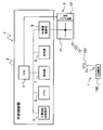
図1により、本発明の一実施形態の無線タグ通信装置としての無線タグ通信装置1の使用態様の一例を説明する。
図1において、この例では、図書館の書棚Sに多数の書籍Bが収納されている。各書籍Bの背表紙には無線タグTが貼付されている。無線タグTには、書籍名、及び著者名等の書籍情報が記憶されている。この例では、2台の無線タグ通信装置1,1が、所定の範囲内で、それぞれ書籍Bに貼付された無線タグTの探索を行っている。具体手的には、無線タグ通信装置1は、無線通信が可能な領域Aに存在する無線タグTに対し情報を送信して、無線タグTから応答信号と上記書籍情報とを受信する。
無線タグ通信装置1は、この例では、携帯型の無線通信装置であり、略直方体形状の筐体2aを有している。筐体2aには、偏波面が縦方向と横方向とで切り替え可能なリーダアンテナユニット3が設けられているとともに、操作部7及び表示部8が設けられている。
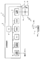
無線タグ通信装置1の概略構成を図2を用いて説明する。
無線タグ通信装置1は、上記筐体2aの内部に設けられた本体制御部2と、アンテナ手段としてのリーダアンテナユニット3とから成る。
リーダアンテナユニット3は、複数のチャンネルを含む所定の周波数範囲、例えば法規の許す全帯域内において、無線タグTに対し無線通信を行う(詳細は後述)ための電波の送受信を行う。リーダアンテナユニット3は、この例では、マイクロストリップアンテナ11と、このマイクロストリップアンテナ11の偏波面を切り替えるための切替スイッチ回路12とを有する。
本体制御部2は、CPU4と、不揮発性記憶装置5と、メモリ6と、上記操作部7と、上記表示部8と、RF通信制御部9とを備えている。
無線タグTは、タグアンテナ151とIC回路部150とを備えた無線タグ回路部Toを有している。無線タグTは、無線タグ回路部Toを、特に図示しない基材などに設けて上記書籍Bに貼付可能にしたものである。前述の図1において、無線タグTは、タグアンテナ151の長手方向の向きが縦方向と横方向のいずれかの方向に向く姿勢で各書籍Bに貼付されている。この例では、ダイポールアンテナであるタグアンテナ151の長手方向を含む面が、電波の電界に対する感度が高い面である。この面を偏波面という。
RF通信制御部9は、上記リーダアンテナユニット3を介し、上記無線タグ回路部ToのIC回路部150に記憶された、タグIDを含む情報へアクセスする。
不揮発性記憶装置5は、ハードディスク装置又はフラッシュメモリからなり、書籍Bの管理状況などの各種情報を記憶する。メモリ6は、例えばRAM又はROM等から構成される。操作部7は、使用者からの指示又は情報が入力される。表示部8は各種情報又はメッセージを表示する。
CPU4は、上記メモリ6内のRAMの一時記憶機能を利用して上記不揮発性記憶装置5に予め記憶されたプログラムに従って信号処理を行い、無線タグ通信装置1全体の各種制御を行う。またCPU4は、無線タグ回路部ToのIC回路部150から読み出された情報を処理するとともに、無線タグ回路部ToのIC回路部150へアクセスするための各種コマンド等を生成する。
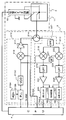
上記RF通信制御部9及びリーダアンテナユニット3の詳細構成を図3を用いて説明する。
RF通信制御部9は、送信部212と、受信部213と、送受分離器214とから構成される。
送信部212は、リーダアンテナユニット3を介し、無線タグ回路部ToのIC回路部150の無線タグ情報にアクセスするための質問波を生成するブロックである。送信部212は、水晶振動子215Aと、Phase Locked Loop(PLL)215Bと、Voltage Controlled Oscillator(VCO)215Cと、送信乗算回路216と、可変送信アンプ217とを備えている。
水晶振動子215Aは、基準周波数を発生する。PLL215Bは、水晶振動子215Aにより発生された基準周波数を元に、VCO215Cの出力する搬送波の周波数が所定周波数となるようにCPU4の命令に基づき制御する。VCO215Cは上記PLL215Bによって発生される制御電圧に基いて決められた周波数の搬送波を出力する。なお、発生される搬送波の周波数としては、例えばUHF帯、マイクロ波帯、あるいは短波帯の周波数が用いられる。
送信乗算回路216は、CPU4から供給される信号に基づいて上記発生させられた搬送波を変調する。この例では、送信乗算回路216は、CPU4からの「TX_ASK」信号に基づく振幅変調を実行する。なお、このような振幅変調の場合、送信乗算回路216に代え、増幅率可変アンプ等を用いてもよい。
可変送信アンプ217は、送信乗算回路216により変調された変調波を増幅する。この例では、可変送信アンプ217は、CPU4からの「TX_PWR」信号によって決定される増幅率により、増幅を行う。そして、送信アンプ217の出力は、送受分離器214を介し、マイクロストリップアンテナ11に伝達されて、質問波としてマイクロストリップアンテナ11から放射され、無線タグ回路部ToのIC回路部150に供給される。なお、質問波は上記のように変調した信号すなわち変調波に限られず、単なる搬送波のみの場合もある。
受信部213は、リーダアンテナユニット3により受信された無線タグ回路部Toからの応答波を入力する。受信部213は、送受分離器214と、バンドパスフィルタ227と、I相受信乗算回路218と、I相ローパスフィルタ219と、I相受信アンプ221と、I相リミッタ220と、移相器227と、Q相受信乗算回路222と、Q相ローパスフィルタ223と、Q相受信アンプ225と、Q相リミッタ224と、強度検出手段としてのReceived Signal Strength Indicator(RSSI)回路226とを備えている。
I相受信乗算回路218は、マイクロストリップアンテナ11で受信され送受分離器214及びバンドパスフィルタ227を介して入力された、無線タグ回路部Toからの応答波と上記発生させられた搬送波とを乗算して復調する。
I相ローパスフィルタ219は、I相受信乗算回路218の出力から必要な帯域の信号のみを取り出す。I相受信アンプ221は、I相ローパスフィルタ219の出力を増幅する。I相リミッタ220は、I相受信アンプ221の出力をさらに増幅してデジタル信号に変換する。
移相器227は、前述のようにして発生した搬送波の位相を90°遅らせる。Q相受信乗算回路222は、上記リーダアンテナユニット3で受信された無線タグ回路部Toからの応答波と、上記移相器227により位相を90°遅らせた搬送波とを乗算する。Q相ローパスフィルタ223は、Q相受信乗算回路222の出力から必要な帯域の信号のみを取り出す。Q相受信アンプ225は、Q相ローパスフィルタ223の出力を増幅する。Q相リミッタ224は、Q相受信アンプ225の出力をさらに増幅してデジタル信号に変換する。
I相リミッタ220から出力される信号「RXS-I」とQ相リミッタ224から出力される信号「RXS-Q」とは、上記CPU4に入力されて処理される。I相受信アンプ221及びQ相受信アンプ225の出力は、RSSI回路226にも入力され、それらの信号の強度を示す信号「RSSI」がCPU4に入力される。上記のようにして、無線タグ通信装置1では、I-Q直交復調によって無線タグ回路部Toからの応答波の復調が行われる。
リーダアンテナユニット3は、前述したように、マイクロストリップアンテナ11と、このマイクロストリップアンテナ11の偏波面を切り替えるための切替スイッチ回路12とを有する。切替スイッチ回路12は、例えば、公知の高周波用FETやダイオードを用いたスイッチ回路である。切替スイッチ回路12は、CPU4からの制御信号によりマイクロストリップアンテナ11に設けられた2つの給電点のいずれかを選択して、送受分離器214に接続する。この切替スイッチ回路12による接続切り替え動作により、マイクロストリップアンテナ11はその偏波面が直交する2方向の面、例えば図2、及び図3中に破線で示す上下方向の面と左右方向の面とのいずれかに切り替えられる。
本実施形態の特徴は、CPU4が、RSSI回路226により検出される受信信号強度に基づき、複数のチャンネルすべてについての使用状況を判定することである。複数のチャンネルすべてが使用されていないと判定された場合に、CPU4は、当該複数のチャンネルのうち使用するチャンネルを選択する。そして、この選択されたチャンネルを用いて、無線タグTと情報の送受信が行われる。
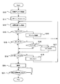
上記の無線タグTとの情報の送受信を実現するために、無線タグ通信装置1のCPU4が実行する制御を図4を用いて説明する。
まず、ステップS10において、CPU4は、リーダアンテナユニット3の各種パラメータについて、適宜の初期アンテナ設定を実行する。この際、CPU4は、切替スイッチ回路12に制御信号を出力し、アンテナ属性としてのマイクロストリップアンテナ11の偏波面が、前述の直交する2方向の面のいずれかに初期的に設定される。
その後、ステップS11に移り、前述した、例えば法規により許される所定の周波数範囲において予め設定される複数のチャンネルに含まれるチャンネル番号を表す変数CH(以下、単に「チャンネル変数CH」と称する)を1に初期化する。また、使用するチャンネルを表すチャンネル番号TX_Ch(以下、単に「チャンネルTX_Ch」と称する)を0に初期化する。
そして、ステップS12に移り、CPU4は、RSSI回路226により検出された受信信号強度Vsを取得する。
その後、ステップS13に移り、CPU4は、ステップS12で取得した受信信号強度Vsが、予め定められた使用状況確認用しきい値V_t1よりも大きいかどうかを判定する。なお、この手順が、各請求項記載の第1判定手段として機能する。
例えば通信中の別の無線タグ通信装置1が近傍にある場合には、受信信号強度Vsが使用状況確認用しきい値V_t1よりも大きくなるためステップS13の判定が満たされ、ステップS14に移る。ステップS14では、CPU4は、切替スイッチ回路12に制御信号を出力し、マイクロストリップアンテナ11の偏波面を、前述の直交する2方向の面のうち、現在使用されている面と直交する面へ切り替える。この手順が、各請求項記載のアンテナ切替手段として機能する。なお、このように同一アンテナの偏波面を切替える代わりに、予めアンテナ属性の異なる複数のアンテナを設けておき、アンテナ切替手段として別のアンテナに切替るようにしても良い。その後、ステップS12に戻り、同様の手順を繰り返す。
一方、ステップS13において、受信信号強度Vsが使用状況確認用しきい値V_t1以下であった場合はステップS14の判定が満たされず、ステップS15に移る。
ステップS15では、CPU4は、この時点でのチャンネルTX_chが0に設定されているかどうかを判定する。TX_ch=0の場合は判定が満たされ、ステップS16に移る。ステップS16では、CPU4は、ステップS12で取得した受信信号強度Vsが、チャンネル選択用しきい値V_t2より小さいかどうかを判定する。ここで、チャンネル選択用しきい値V_t2は、使用状況確認用しきい値V_t1よりも小さい値になるように予め定められている。なお、この手順が、各請求項記載の第2判定手段として機能する。
例えば受信信号強度Vsがチャンネル選択用しきい値V_t2より小さい場合は、ステップS16の判定が満たされ、ステップS17に移行する。ステップS17では、CPU4は、通信に使用するチャンネルTX_chを、この時点での変数CHの値に設定する。なお、この手順が、各請求項記載のチャンネル選択手段として機能する。その後、ステップS18に移行する。
一方、例えば受信信号強度Vsがチャンネル選択用しきい値V_t2以上である場合には、ステップS16の判定が満たされず、後述のステップS18に移行する。
ステップS18では、CPU4は、この時点でのチャンネル変数CHが、前述の所定の周波数範囲において予め設定されたチャンネル数のうち、チャンネル番号の最大値に対応したCH_maxに達したかどうかを判定する。チャンネル変数CHがCH_maxまで達していなければステップS18の判定が満たされず、ステップS19に移る。
ステップS19では、無線通信で使用するチャンネルを切り替えるため、チャンネル変数CHに1を加える。なお、この手順が、各請求項記載のチャンネル切替手段として機能する。その後、ステップS12に戻り、次のチャンネルに対して同様の手順を繰り返す。
一方、ステップS18において、チャンネル変数CHがCH_maxと等しくなっていた場合はステップS18の判定が満たされ、ステップS20に移る。ステップS20では、この時点で使用するとして設定されているチャンネルTX_chを用いて、リーダアンテナユニット3を介し、無線タグTと無線通信を行う。なお、この手順が、各請求項記載の通信動作決定手段及び送受信制御手段として機能する。
その後、ステップS21に移り、CPU4は、所定の待ち時間が経過したかどうかを判定する。待ち時間が経過するまでは判定が満たされずループ待機し、待ち時間が経過したらステップS21の判定が満たされ、このフローを終了する。言い換えれば、次回このフローが再び開始されるより前に、当該待ち時間だけリーダアンテナユニット3による無線通信が禁止されることとなる。この結果、近傍に存在する他の無線タグ通信装置1が図4と同様なフローのステップS10からステップS19を繰り返した結果、電波を出して良いと判断され、通信を開始できるようになる。すなわち、ステップS21は、各請求項記載の禁止制御手段として機能する。
以上説明したように、本実施形態の無線タグ通信装置1では、ステップS20において無線通信を実行するに際して、RSSI回路226で検出される受信信号強度Vsに基づき、ステップS13、ステップS16、ステップS18、及びステップS19等により、複数のチャンネルすべてについての使用状況を判定する。そして、複数のチャンネルすべてが使用されていないと判定された場合に、ステップS17で選択されたチャンネルを用いて、ステップS20において、無線タグTと無線通信を行う。
これにより、周波数選択機能のない無線タグT側において混信が生じるのを抑制することができる。また、複数の無線タグ通信装置1相互において混信が生じるのを抑制することができる。すなわち、他の無線タグ通信装置1が無線タグTと通信をしているのに対して影響を与えないようにすることができる。この結果、複数のチャンネルのうち不使用のチャンネルを確認し当該チャンネルを使用して無線通信を行う従来技術に比べ、通信の確実性を向上することができる。したがって、複数の無線タグ通信装置1を含む通信システム全体として、無線通信の信頼性を向上することができる。
なお、必ずしも、上記のような、複数のチャンネルすべてが使用されていないことを確認した後、無線タグTに対し無線通信を行う手法でなくてもよい。すなわち、いずれか1つのチャンネルの使用が確認されたとき、そのチャネルにおける受信電力に応じ、ステップS20において、CPU4が、可変送信アンプ217を制御して送信出力を適宜の小さい値に制限して、無線タグTと通信を行うようにしてもよい。この場合、無線タグ通信装置1の通信範囲と近傍の他の無線タグ通信装置1の通信範囲との重なり具合を調整することができるため、上記とほぼ同様に、複数の無線タグ通信装置1相互において混信が生じるのを抑制でき、他の無線タグ通信装置1が無線タグTと通信をしているのに対して与える影響を小さくすることができる。
また、本実施形態では特に、ステップS20での情報無線通信完了後、ステップS21により、所定の時間無線通信を行わないようにする。この結果、この所定の時間の間に、それまで無線タグ通信装置1の通信によって通信が開始できなかった近傍の他の無線タグ通信装置1が通信を開始できるため、他の無線タグ通信装置1が通信できなくなるのを防止することができる。
また、本実施形態では特に、ステップS18及びステップS19において、切り替えられる各チャンネルごとに、ステップS13でRSSI回路226により検出される受信信号強度Vsが使用状況確認用しきい値V_t1より大きいかどうかが判定される。このように、複数のチャンネルを切り替えながらチャンネルごとに判定を行うことにより、図3を用いて説明したように、受信側の回路の構成を簡素化することができる。この結果、従来から使用されている汎用のキャリアセンス回路を流用することも可能となる。
また、本実施形態では特に、ステップS13で受信信号強度Vsが使用状況確認用しきい値V_t1より大きいかどうかが判定された後、さらにステップS16で、受信信号強度Vsがチャンネル選択用しきい値V_t2より小さいかどうかが判定される。これには以下のような意義がある。すなわち、通常用いられるチャンネル選択用しきい値V_t2は、複数の無線タグ通信装置1同士の間隔が離れていて相互に干渉し合う場合を想定し、比較的低い値に設定される場合が多い。無線タグTにおける干渉の発生を想定した場合、無線タグ通信装置1と無線タグTとの間ではより強力な電波が必要であるため、使用状況確認用しきい値V_t1としては、上記チャンネル選択用しきい値V_t2よりも大きな値を用いることが好ましい。そこで本実施形態においては、チャンネル選択用しきい値V_t2は使用状況確認用しきい値V_t1よりも小さくなるような関係となるように、両しきい値を用いる。これにより、前述のステップS13及びステップS16において、上記の趣旨に添った合理的かつ有効な判定を行うことができる。
また、本実施形態では特に、ステップS13で受信信号強度Vsが使用状況確認用しきい値V_t1より大きいと判定された場合、ステップS14で、マイクロストリップアンテナ11の偏波面を切り替える。これには以下のような意義がある。すなわち、このマイクロストリップアンテナ11のように偏波面などのアンテナ属性が複数の態様に切り替え可能となっている場合、各態様ごとに通信範囲又は通信対象となる無線タグTが異なるため、各態様ごとに使用状態を確認することが好ましい。そこで、本実施形態では、ステップS13での判定が満たされ複数チャンネルのいずれかが使用されていると判定された場合に、ステップS14でアンテナ属性としての偏波面を切り替える。そして、その切り替えられた後の受信信号強度Vsを検出し、その検出した強度に基づき、複数のチャンネルすべての使用状況を判定する。これにより、複数の無線タグ通信装置1相互の混信発生及び無線タグT側の混信発生を防止できるアンテナ態様を見つけ出し、当該アンテナ態様において信頼性の高い情報無線通信を行うことができる。
なお、本発明は上記に限られず、技術的思想を逸脱しない範囲で種々の変形が可能である。以下、そのような変形例を順を追って説明する。
(1)複数のチャンネルについて一括して判定を行う場合
上記実施形態においては、ステップS13及びステップS19により、RSSI回路226で検出される受信信号強度Vsが使用状況確認用しきい値V_t1より大きいかどうかを、複数のチャンネルについて個別に判定した。本変形例では、この手法に代えて、受信信号強度Vsが使用状況確認用しきい値V_t1より大きいかどうかを、複数のチャンネルについて一括して判定する。
上記実施形態においては、ステップS13及びステップS19により、RSSI回路226で検出される受信信号強度Vsが使用状況確認用しきい値V_t1より大きいかどうかを、複数のチャンネルについて個別に判定した。本変形例では、この手法に代えて、受信信号強度Vsが使用状況確認用しきい値V_t1より大きいかどうかを、複数のチャンネルについて一括して判定する。
本変形例におけるRF通信制御部9及びリーダアンテナユニット3の詳細構成を図3を用いて説明する。図3に示すように、本実施形態のRF通信制御部9では、上記I相ローパスフィルタ219及び上記Q相受信ローパスフィルタ223が設けられているが、本変形例では、上記I相ローパスフィルタ219及び上記Q相受信ローパスフィルタ223に加えて、これら両ローパスフィルタ219,223よりも広い帯域、理想的には法規で許されている帯域幅の略半分の帯域幅、で信号を取り出すことのできるI相ローパスフィルタ及びQ相ローパスフィルタが設けられる。その他は図3と同様であり、説明を省略する。
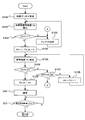
本変形例の無線タグ通信装置1のCPU4が実行する制御を図5を用いて説明する。
まずステップS100で、上記図4のステップS10と同様、CPU4は、初期アンテナ設定を行う。その後、ステップS101に移る。
ステップS101では、CPU4は、RSSI回路226により検出された、すべての帯域にわたる全帯域信号強度Vaを取得する。
その後、ステップS102に移り、CPU4は、ステップS101で取得した全帯域受信信号強度Vaが、予め定められた使用状況確認用しきい値V_t1′よりも大きいかどうかを判定する。なお、この手順が、各請求項記載の第1判定手段として機能する。
例えば通信中の別の無線タグ通信装置1が近傍にある場合には、全帯域受信信号強度Vaが使用状況確認用しきい値V_t1′よりも大きくなるためステップS102の判定が満たされ、ステップS103に移る。ステップS103では、CPU4は、前述の図4のステップS14と同様、切替スイッチ回路12に制御信号を出力し、マイクロストリップアンテナ11の偏波面を、前述の直交する2方向の面のうち、現在使用されている面と直交する面へ切り替える。この手順が、各請求項記載のアンテナ切替手段として機能する。その後、ステップS101に戻り、同様の手順を繰り返す。
一方、ステップS102において、全帯域受信信号強度Vaが使用状況確認用しきい値V_t1′以下であった場合はステップS102の判定が満たされず、ステップS104に移る。
ステップS104では、前述の図4のステップS11と同様、所定の周波数範囲において予め設定される複数のチャンネルに含まれるチャンネル番号を表すチャンネル変数CHを1に初期化する。また、使用するチャンネルを表すチャンネルTX_Chを0に初期化する。
その後、ステップS105に移り、CPU4は、上記図4のステップS12と同様、RSSI回路226により検出された受信信号強度Vsを取得する。
そして、ステップS106に移り、上記図4のステップS16と同様、ステップS105で取得した受信信号強度Vsが、上記使用状況確認用しきい値V_t1′よりも小さく予め定められた、チャンネル選択用しきい値V_t2より小さいかどうかを判定する。なお、この手順が、各請求項記載の第2判定手段として機能する。
受信信号強度Vsがチャンネル選択用しきい値V_t2より小さい場合、ステップS106の判定が満たされ、後述のステップS109に移行する。
一方、受信信号強度Vsがチャンネル選択用しきい値V_t2以上である場合には、ステップS106の判定が満たされず、ステップS107に移行する。ステップS17では、CPU4は、上記図4のステップS18と同様、この時点でのチャンネル変数CHがCH_maxに達したかどうかを判定する。チャンネル変数CHがCH_maxまで達していなければステップS107の判定が満たされず、ステップS108に移る。
ステップS108では、上記図4のステップS19と同様、無線通信で使用するチャンネルを切り替えるため、チャンネル変数CHに1を加える。なお、この手順が、各請求項記載のチャンネル切替手段として機能する。その後、ステップS105に戻り、同様の手順を繰り返す。
一方、ステップS107において、チャンネル変数CHがCH_maxと等しくなっていた場合は判定が満たされ、上記ステップS103に戻り、同様の手順を繰り返す。
ステップS109では、上記図4のステップS17と同様、CPU4は、通信に使用するチャンネルTX_chを、この時点での変数CHの値に設定する。なお、この手順が、各請求項記載のチャンネル選択手段として機能する。その後、図4と同様のステップS20及びステップS21については説明を省略する。
本変形例によっても、上記実施形態と同様の効果を得る。また、ステップS101及びステップS102において全チャンネルについて一括して判定を行うことにより、上記実施形態のように複数のチャンネルを切り替えながらチャンネルごとに判定を行う場合に比べ、迅速に判定を行うことができる。
(2)複数の無線タグ通信装置間で通信を行い、協調する場合
すなわち、上記のような複数の無線タグ通信装置1における混信の低減を図る際、上記実施形態又は(1)の変形例の手法に加え、当該複数の無線タグ通信装置1同士の間で通信を行って協調するようにしてもよい。
すなわち、上記のような複数の無線タグ通信装置1における混信の低減を図る際、上記実施形態又は(1)の変形例の手法に加え、当該複数の無線タグ通信装置1同士の間で通信を行って協調するようにしてもよい。
本変形例の無線タグ通信装置1の概略システム構成を図6に示す。図6に示すように、本変形例の無線タグ通信装置1の本体制御部2には、他の無線タグ通信装置1と通信を行うためのリーダ通信手段として、近距離通信部10が備えられている。
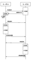
本変形例において複数の無線タグ通信装置1同士の間で実行する協調制御を概念的に図7に示す。図7に示すように、無線タグTとの通信を実行しようとする一方の無線タグ通信装置1(図では「リーダA」として示している)のCPU4は、上記近距離通信部10を用いて、他の無線タグ通信装置1(図では「リーダB」として示している)に対し無線通信の停止を要求する停波要求信号を送信する。他の無線タグ通信装置1は、その時点で無線タグTとの通信を実行中の場合は、一方の無線タグ通信装置1に対し通信状態信号としての通信中フラグ信号を送信し、通信中でない場合は何も応答しない。一方の無線タグ通信装置1は、当該停波要求信号に対応した、他の無線タグ通信装置1からの通信中フラグ信号を受信した場合、他の無線タグ通信装置1に対し一定時間後に再度停波要求信号を送信する。一方の無線タグ通信装置1は、停波要求信号送信後一定時間の間、他の無線タグ通信装置1からの通信中フラグ信号を受信しない場合、近傍にある他の無線タグ通信装置1は上記停波要求信号によって停波状態になったと判断し、上記実施形態又は(1)の変形例の手法により、受信信号強度Vsに基づき複数のチャンネルすべてについての使用状況を判定し、無線タグTと無線通信を行う。
無線タグTとの無線通信が終了したら、一方の無線タグ通信装置1は、他の無線タグ通信装置1に対し、無線通信の停止要求を解除する停波要求解除信号を送信する。
上記他の無線タグ通信装置1が無線タグTとの通信を開始しようとする場合も、上記一方の無線タグ通信装置1が実行したのと同様の手順を実行する。すなわち、上記近距離通信部10を用いて停波要求信号を送信し、一定時間内に通信中フラグ信号を受信しなかった場合、無線タグTとの無線通信を行い、情報無線通信終了後に停波要求解除信号を送信する。
本変形例の無線タグ通信装置1のCPU4が実行する制御を図8を用いて説明する。上述の図5と同等の手順には同じステップ番号を付し、説明を省略又は簡略化する。なお、図8の例では、前述の(1)の変形例の手法に無線タグ通信装置1同士の協調制御を適用した場合を示している。
まず、ステップS199で、CPU4は、現在、他の無線タグ通信装置1から停波要求を受けている(停波解除されてない)状態かどうかを判定する。他の無線タグ通信装置1から停波要求を受けていない状態の場合には通信を行えるため、ステップS199の判定が満たされず、後述のステップS200に移る。一方、他の無線タグ通信装置1から停波要求を受けている状態の場合、通信を開始することができないため、ステップS199の判定が満たされ、ステップS198にて所定時間待機した後、ステップS197に移る。
ステップS197では、CPU4は、停波解除を受信したかどうかを判定する。停波解除を受信しない場合、ステップS197の判定が満たされず、上記ステップS198に戻り所定時間待機した後、再びこのステップS197を繰り返す。停波解除を受信すれば、通信を開始できるため、ステップS197の判定が満たされてステップS200に移る。
ステップS200で、CPU4は、近距離通信部10により、他の無線タグ通信装置1に対し無線通信の停止を要求する上記停波要求信号を送信する。なお、この手順が、各請求項記載の停波要求送信手段として機能する。
その後、ステップS201に移り、一定時間内に上記ステップS200で送信した停波要求信号に対応した、他の無線タグ通信装置1からの通信中フラグ信号が近距離通信部10により受信されたかどうかを判定する。なお、この手順が、各請求項記載の通信状態受信手段として機能する。他の無線タグ通信装置1が通信中でない状態の場合は通信中フラグ信号が他の無線タグ通信装置1から送信されない。このため、一定時間内に通信中フラグを受信しなければ同時に通信をしている無線タグ通信装置が存在しないものと考えられ、ステップS201の判定は満たされず、ステップS101に移る。一方、他の無線タグ通信装置1が送信した通信中フラグを受信した場合はステップS201の判定が満たされ、ステップS202にて所定時間待機した後、ステップS200に戻り、同様の手順を繰り返す。
ステップS101~ステップS109及びステップS20は、上記図5と同様であるため、説明を省略する。
ステップS20における無線タグTとの通信が終了したら、ステップS300へ移る。
ステップS300では、CPU4は、近距離通信部10により、他の無線タグ通信装置1に対し無線通信の停止要求を解除する停波要求解除信号を送信し、前述のステップS21に移る。ステップS21については前述と同様であり、説明を省略する。
本変形例においては、近距離通信部10を用いて、複数の無線タグ通信装置1相互が協調するような動作を行う。このような協調動作を行うことにより、上述したように、1つの無線タグ通信装置1が無線通信を実行する際、協調する他の無線タグ通信装置1は無線通信を停止するので、迅速かつ確実に全チャンネルの不使用を確認し情報無線通信を開始することができる。この結果、情報伝達効率を向上することができる。また、複数の無線タグ通信装置1相互がコミュニケーションをとって協調動作を行うことにより、複数の無線タグ通信装置を制御するための上位コントローラを設ける必要がないという効果もある。
なお、本変形例において無線タグ通信装置1同士の通信に用いる近距離通信は、赤外線通信、Bluetooth(登録商標)又はその他のブロードキャスト通信を用いてもよく、あるいは上記所定の周波数帯域の中の特定のチャンネルを専用に用いるようにしてもよい。
(3)その他
以上においては、通信を行うチャンネルを選択するチャンネル選択手段として、各チャンネルの受信信号強度Vsがチャンネル選択用しきい値V_t2より小さいかどうかを判定し、この判定を満たすチャンネルを通信チャネルとした(ステップS16、ステップS106参照)。しかしながら、この方法に限らず、通信を行うチャンネルを規定時間内に擬似ランダム的に順次切り替える方法を用いても良い。この方法を用いる場合、通信チャネル数が十分確保できれば、無線タグ通信装置1同士が同じチャネルを使う確率が下がり、無線タグ通信装置1間の干渉が発生し難くなる。この場合、前述の各請求項記載の第2判定手段は必ずしも必要としない。
以上においては、通信を行うチャンネルを選択するチャンネル選択手段として、各チャンネルの受信信号強度Vsがチャンネル選択用しきい値V_t2より小さいかどうかを判定し、この判定を満たすチャンネルを通信チャネルとした(ステップS16、ステップS106参照)。しかしながら、この方法に限らず、通信を行うチャンネルを規定時間内に擬似ランダム的に順次切り替える方法を用いても良い。この方法を用いる場合、通信チャネル数が十分確保できれば、無線タグ通信装置1同士が同じチャネルを使う確率が下がり、無線タグ通信装置1間の干渉が発生し難くなる。この場合、前述の各請求項記載の第2判定手段は必ずしも必要としない。
また、以上既に述べた以外にも、上記実施形態又は各変形例による手法を適宜組み合わせて利用しても良い。
その他、一々例示はしないが、本発明は、その趣旨を逸脱しない範囲内において、種々の変更が加えられて実施されるものである。
1 無線タグ通信装置
3 リーダアンテナユニット(アンテナ手段)
10 赤外線通信部(リーダ通信手段)
11 マイクロストリップアンテナ
12 切替スイッチ回路
150 IC回路部
151 タグアンテナ
226 RSSI回路(強度検出手段)
T 無線タグ
To 無線タグ回路部
3 リーダアンテナユニット(アンテナ手段)
10 赤外線通信部(リーダ通信手段)
11 マイクロストリップアンテナ
12 切替スイッチ回路
150 IC回路部
151 タグアンテナ
226 RSSI回路(強度検出手段)
T 無線タグ
To 無線タグ回路部
Claims (9)
- 複数のチャンネルを含む所定の周波数範囲内において、無線タグに対し無線通信を行うアンテナ手段と、
前記アンテナ手段により受信される信号の信号強度を検出する検出手段と、
前記検出手段により検出される信号強度に基づき、前記複数のチャンネルすべてについての使用状況を判定する第1判定手段と、
前記第1判定手段により、前記複数のチャンネルすべてが使用されていないと判定された場合と、前記複数のチャンネルのうちいずれかが使用されていると判定された場合とで異なる通信動作を決定する決定手段と、
前記第1判定手段により判定される使用状況により、当該複数のチャンネルのうち使用していないチャンネルを選択するチャンネル選択手段と、
前記チャンネル選択手段により選択される前記チャンネルを用いて、前記アンテナ手段により、前記決定手段が決定した通信動作で前記無線タグとの無線通信を行うように制御する第1制御手段とを有することを特徴とする無線タグ通信装置。 - 前記決定手段は、
前記第1判定手段により前記複数のチャンネルすべてが使用されていないと判定された場合に、前記第1制御手段により無線通信を行うよう決定することを特徴とする請求項1記載の無線タグ通信装置。 - 前記決定手段は、
前記第1判定手段により前記複数のチャンネルのうちいずれかが使用されていると判定された場合、前記検出手段により検出される送信出力とは異なる送信出力で送信を行う通信動作を決定することを特徴とする請求項1記載の無線タグ通信装置。 - 所定の時間、前記アンテナ手段による無線通信を禁止する制御を行う第2制御手段を備え、
前記第1制御手段による無線通信の制御が完了した場合に、前記第2制御手段は、所定の時間、前記アンテナ手段による無線通信を禁止する
こと特徴とする請求項1記載の無線タグ通信装置。 - 前記アンテナ手段による無線通信で使用する前記チャンネルを切り替えるチャンネル切替手段をさらに有し、
前記第1判定手段は、
前記チャンネル切替手段により切り替えられる各チャンネルごとに、前記検出手段により検出される受信した信号強度が使用状況を確認するための確認用しきい値より大きいかどうかを判定する
ことを特徴とする請求項1記載の無線タグ通信装置。 - 前記第1判定手段は、
前記検出手段により検出される受信した信号強度が使用状況を確認するための確認用しきい値より大きいかどうかを、前記複数のチャンネルについて一括して判定する
ことを特徴とする請求項1記載の無線タグ通信装置。 - 前記確認用しきい値よりも小さい値であるチャンネルを選択するための選択用しきい値を用いて、前記検出手段により検出される信号強度が、当該選択用しきい値よりも大きいかどうかを判定する第2判定手段をさらに有し、
前記チャンネル選択手段は、
前記複数のチャンネルのうち、前記第2判定手段により、前記信号強度が前記選択用しきい値以下であると判定されたチャンネルを、使用するチャンネルとして選択する
ことを特徴とする請求項5又は請求項6記載の無線タグ通信装置。 - 前記第1判定手段により、前記複数のチャンネルのうちいずれかが使用されていると判定された場合に、前記アンテナ手段又は前記アンテナ手段の偏波面を切り替えるアンテナ切替手段をさらに有し、
前記検出手段は、
前記アンテナ切替手段により前記アンテナ手段又は前記アンテナ手段の偏波面が切り替えられた後の前記アンテナ手段により受信される信号強度を検出し、
前記第1判定手段は、
前記アンテナ切替手段により前記アンテナ手段又は前記アンテナ手段の偏波面が切り替えられた後の、前記検出手段により検出される信号強度に基づき、前記複数のチャンネルすべてについての使用状況を判定する
ことを特徴とする請求項1記載の無線タグ通信装置。 - 他の無線タグ通信装置と通信を行うための通信手段と、
前記通信手段を用いて前記他の無線タグ通信装置に対し無線通信の停止を要求する要求信号を送信する送信手段と、
前記送信手段からの前記要求信号に対応した、前記他の無線タグ通信装置からの通信状態を応答する応答信号を受信する受信手段と
をさらに有し、
前記第1判定手段は、
前記受信手段が前記応答信号を受信しなかった場合に、前記検出手段により検出される信号強度に基づき、前記複数のチャンネルすべてについての使用状況を判定する
ことを特徴とする請求項1乃至4のいずれか1項記載の無線タグ通信装置。
Applications Claiming Priority (2)
| Application Number | Priority Date | Filing Date | Title |
|---|---|---|---|
| JP2009-223501 | 2009-09-28 | ||
| JP2009223501A JP2011070606A (ja) | 2009-09-28 | 2009-09-28 | 無線タグ通信装置 |
Publications (1)
| Publication Number | Publication Date |
|---|---|
| WO2011037152A1 true WO2011037152A1 (ja) | 2011-03-31 |
Family
ID=43795898
Family Applications (1)
| Application Number | Title | Priority Date | Filing Date |
|---|---|---|---|
| PCT/JP2010/066459 Ceased WO2011037152A1 (ja) | 2009-09-28 | 2010-09-23 | 無線タグ通信装置 |
Country Status (2)
| Country | Link |
|---|---|
| JP (1) | JP2011070606A (ja) |
| WO (1) | WO2011037152A1 (ja) |
Cited By (3)
| Publication number | Priority date | Publication date | Assignee | Title |
|---|---|---|---|---|
| JP2021124793A (ja) * | 2020-01-31 | 2021-08-30 | 太陽誘電株式会社 | 部品流動検出システムおよび受信機 |
| JPWO2021192276A1 (ja) * | 2020-03-27 | 2021-09-30 | ||
| EP4726601A1 (en) * | 2024-09-26 | 2026-04-15 | Hand Held Products, Inc. | Radio frequency identification (rfid) reader and a method for switching antenna polarization of rfid reader |
Families Citing this family (3)
| Publication number | Priority date | Publication date | Assignee | Title |
|---|---|---|---|---|
| JP2014165871A (ja) * | 2013-02-27 | 2014-09-08 | Maspro Denkoh Corp | テレビ放送再送信システム |
| JP2017167835A (ja) * | 2016-03-16 | 2017-09-21 | 株式会社東芝 | タグ読み取り装置、照合装置、タグ読み取り方法およびプログラム |
| JP7496609B2 (ja) * | 2020-09-02 | 2024-06-07 | 株式会社Kmc | センサシステム、子タグ及び情報処理プログラム |
Citations (2)
| Publication number | Priority date | Publication date | Assignee | Title |
|---|---|---|---|---|
| JP2007067621A (ja) * | 2005-08-30 | 2007-03-15 | Fujitsu Ltd | Rfid質問器及びデータ通信方法 |
| JP2008270978A (ja) * | 2007-04-17 | 2008-11-06 | Toshiba Tec Corp | 無線通信装置 |
-
2009
- 2009-09-28 JP JP2009223501A patent/JP2011070606A/ja active Pending
-
2010
- 2010-09-23 WO PCT/JP2010/066459 patent/WO2011037152A1/ja not_active Ceased
Patent Citations (2)
| Publication number | Priority date | Publication date | Assignee | Title |
|---|---|---|---|---|
| JP2007067621A (ja) * | 2005-08-30 | 2007-03-15 | Fujitsu Ltd | Rfid質問器及びデータ通信方法 |
| JP2008270978A (ja) * | 2007-04-17 | 2008-11-06 | Toshiba Tec Corp | 無線通信装置 |
Cited By (3)
| Publication number | Priority date | Publication date | Assignee | Title |
|---|---|---|---|---|
| JP2021124793A (ja) * | 2020-01-31 | 2021-08-30 | 太陽誘電株式会社 | 部品流動検出システムおよび受信機 |
| JPWO2021192276A1 (ja) * | 2020-03-27 | 2021-09-30 | ||
| EP4726601A1 (en) * | 2024-09-26 | 2026-04-15 | Hand Held Products, Inc. | Radio frequency identification (rfid) reader and a method for switching antenna polarization of rfid reader |
Also Published As
| Publication number | Publication date |
|---|---|
| JP2011070606A (ja) | 2011-04-07 |
Similar Documents
| Publication | Publication Date | Title |
|---|---|---|
| JP5491331B2 (ja) | 通信モード設定装置 | |
| JP4387323B2 (ja) | Rfid用送受信装置 | |
| JP4716195B2 (ja) | 無線タグ通信装置 | |
| US20150126116A1 (en) | Mobile wireless communications device including nfc antenna matching control circuit and associated methods | |
| JP2011070606A (ja) | 無線タグ通信装置 | |
| JP4557086B2 (ja) | 電波受信装置 | |
| US12119891B2 (en) | Contactless card reading employing gain and attenuation control | |
| CN113170377A (zh) | 一种网络连接建立方法及相应的装置 | |
| KR20080097115A (ko) | 무선 주파수 식별 장치 | |
| WO2018095114A1 (zh) | 一种移动终端及调谐天线的方法、装置及存储介质 | |
| JP2009135610A (ja) | 通信システム並びに通信装置 | |
| KR20070109900A (ko) | 모바일 rfid 기능을 갖는 이동통신 단말을 위한전력증폭기 공유 시스템 | |
| KR102013419B1 (ko) | Rfid 통신 모드 선택 방법 및 근거리장 통신 및 원거리장 통신을 지원하는 rfid 장치 | |
| JP4604964B2 (ja) | 送受信装置、変調集積回路およびrfidリーダライタ | |
| JP4537248B2 (ja) | キャリアセンス方法及び送受信装置 | |
| JP5548075B2 (ja) | 通信出力設定装置 | |
| US9755679B1 (en) | Load dependent receiver configuration | |
| JP5416065B2 (ja) | 通信モード設定装置 | |
| KR102718667B1 (ko) | Nfc 보조 장치 및 방법 | |
| JP2006217200A (ja) | 無線通信装置 | |
| JPWO2006082612A1 (ja) | Rfidキャリアセンス方法及び,これを用いるrfidシステム | |
| KR101136136B1 (ko) | 다중 대역 사용 가능한 근거리 무선 송수신기 | |
| CN113765528B (zh) | 可重构天线、电子设备以及调谐控制方法 | |
| KR20160011476A (ko) | 차량용 블루투스 장치 및 그 제어방법 | |
| JP2008283637A (ja) | 無線通信装置 |
Legal Events
| Date | Code | Title | Description |
|---|---|---|---|
| 121 | Ep: the epo has been informed by wipo that ep was designated in this application |
Ref document number: 10818825 Country of ref document: EP Kind code of ref document: A1 |
|
| NENP | Non-entry into the national phase |
Ref country code: DE |
|
| 122 | Ep: pct application non-entry in european phase |
Ref document number: 10818825 Country of ref document: EP Kind code of ref document: A1 |