WO2011033922A1 - 入力システム、入力装置及び入力方法 - Google Patents
入力システム、入力装置及び入力方法 Download PDFInfo
- Publication number
- WO2011033922A1 WO2011033922A1 PCT/JP2010/064637 JP2010064637W WO2011033922A1 WO 2011033922 A1 WO2011033922 A1 WO 2011033922A1 JP 2010064637 W JP2010064637 W JP 2010064637W WO 2011033922 A1 WO2011033922 A1 WO 2011033922A1
- Authority
- WO
- WIPO (PCT)
- Prior art keywords
- input
- input device
- time stamp
- detection data
- synchronization
- Prior art date
- Legal status (The legal status is an assumption and is not a legal conclusion. Google has not performed a legal analysis and makes no representation as to the accuracy of the status listed.)
- Ceased
Links
Images





Classifications
-
- G—PHYSICS
- G06—COMPUTING OR CALCULATING; COUNTING
- G06F—ELECTRIC DIGITAL DATA PROCESSING
- G06F3/00—Input arrangements for transferring data to be processed into a form capable of being handled by the computer; Output arrangements for transferring data from processing unit to output unit, e.g. interface arrangements
- G06F3/01—Input arrangements or combined input and output arrangements for interaction between user and computer
- G06F3/011—Arrangements for interaction with the human body, e.g. for user immersion in virtual reality
- G06F3/014—Hand-worn input/output arrangements, e.g. data gloves
-
- G—PHYSICS
- G06—COMPUTING OR CALCULATING; COUNTING
- G06F—ELECTRIC DIGITAL DATA PROCESSING
- G06F3/00—Input arrangements for transferring data to be processed into a form capable of being handled by the computer; Output arrangements for transferring data from processing unit to output unit, e.g. interface arrangements
- G06F3/01—Input arrangements or combined input and output arrangements for interaction between user and computer
- G06F3/017—Gesture based interaction, e.g. based on a set of recognized hand gestures
Definitions
- the present invention relates to an input system, an input device, and an input method for determining input data based on detection data indicating a user's hand movement.
- Patent Document 1 proposes a data input device that can input data by hand gestures.
- data output with time from a sensor attached to the user's finger is scanned at a predetermined cycle.
- the scan data acquired within a predetermined time is analyzed, and the movement of the finger is recognized. It is determined that information corresponding to the recognized finger movement has been input.
- the sensor attached to the left hand side and the sensor attached to the right hand side each have a time stamp clock to indicate the time of data output.
- time stamp clocks indicate numerical values indicating different times, there is a problem that the data input device cannot recognize the data in the order intended by the user.
- the present invention has been made to solve the above-described problems, and an object of the present invention is to provide an input system, an input device, and an input method capable of inputting data in an order instructed by a user's hand movement. .
- an input system includes a sensor that is attached to a hand and generates an electrical signal corresponding to the movement of the hand, and the electrical signal generated by the sensor.
- An input device including an output unit that outputs detection data, and a storage unit, and a pattern of the detection data that is output when the hand to which the sensor is attached has a predetermined movement, and a predetermined unit Corresponding to the detection data based on the comparison result between the pattern acquisition means for acquiring the input data in association with the input data, the detection data output by the output means, and the pattern acquired by the pattern acquisition means Determining means for determining the input data; the electrical signal generated by the sensor; and the input data determined by the determining means.
- the determining means A process for determining the input data corresponding to the detection data is executed according to an operation mode that defines a process executed in the input system, and the input system is the input device attached to one hand.
- Reset mode setting means for setting the mode to be set, and when the operation mode of the input system is the reset mode, the detection data output from the first input device and the second input device.
- the signal acquisition means for acquiring the detection data as a synchronization signal, the processing for correcting the time stamp clock when the synchronization signal is acquired by the signal acquisition means, and the time stamp giving means
- a synchronization unit that executes the synchronization process by executing at least one of a process for obtaining a correction amount of the time stamp that is performed, and when the synchronization process is performed by the synchronization unit,
- the operation mode is input to execute the process of determining the input data by the determining means.
- Input mode setting means for setting the mode.
- the reset mode setting means is configured to operate the input system when the input system is powered on.
- the mode is set to the reset mode.
- an input system of an invention according to claim 3 is output from the detection data output from the first input device and the second input device.
- the operation mode of the input system is changed to a standby mode in which processing for determining the input data by the determination unit is stopped.
- An input system is the input system according to any one of the first to third aspects, wherein the signal acquisition means includes the detection data output from the first input device.
- the detection data output from the second input device changes the electrical signals of all the sensors included in the first input device and the second input device within a predetermined period. In the case where it indicates that the data is detected, the detection data is acquired as the synchronization signal.
- An input device is an input device used in an input system for determining input data according to detection data indicating hand movement, attached to one hand, With reference to a sensor that generates an electrical signal in accordance with movement, output means for outputting detection data including the electrical signal generated by the sensor, and storage means, the hand to which the sensor is attached is A pattern acquisition unit that associates and acquires a pattern of the detection data that is output in the case of movement and predetermined input data, the detection data that is output by the output unit, and is acquired by the pattern acquisition unit A determination means for determining the input data corresponding to the detection data based on a comparison result with the pattern, and generated by the sensor; A time stamp giving means for giving a time stamp defining an input order of the input data to at least one of the electrical signal and the input data determined by the determining means with reference to a time stamp clock; Signal acquisition means for acquiring the detection data output by the output means as a synchronization signal; processing for correcting the timestamp clock when the synchronization signal is
- the input device of the invention according to claim 6 has an operation mode that defines processing executed in the input system according to a use state of the input system.
- the reset mode setting means for setting the reset mode for executing the synchronization processing, and when the synchronization processing is executed by the synchronization means, the operation mode of the input system is changed based on the detection data.
- Input mode setting means for setting to an input mode in which the determining process is executed, and the signal acquisition means outputs the synchronization signal when the operation mode of the input system is set to the reset mode. get.
- an input method that uses an input system including a first input device and a second input device, and inputs input data corresponding to detected data indicating hand movement to a computer. And an output process for outputting detection data including an electrical signal corresponding to the movement of the hand generated by a sensor attached to the hand, and referring to the storage means.
- the pattern acquisition step of acquiring the pattern of the detection data output when the attached hand moves in a predetermined manner and the predetermined input data in association with each other, and according to the operation mode of the input system, Based on the comparison result between the detection data output in the output step and the pattern acquired in the pattern acquisition step, the detection data corresponding to the detection data
- a determination step for determining force data and a time stamp defining an input order of the input data with respect to at least one of the electrical signal generated by the sensor and the input data determined in the determination step;
- a time stamp applying step that is applied with reference to a time stamp clock, and according to a use state of the input system, the operation mode of the input system is changed between the first input device and the second input device.
- a reset mode setting step for setting a reset mode for executing a synchronization process for eliminating at least one of the time stamp clock and the time stamp; and when the operation mode of the input system is the reset mode, The detection data output from the first input device and the second input device.
- a signal acquisition step of acquiring the detection data output from the signal as a synchronization signal, a process of correcting the time stamp clock when the synchronization signal is acquired in the signal acquisition step, and the time stamp addition By executing at least one of the process for obtaining the correction amount of the time stamp given by the means, the synchronization process for executing the synchronization process, and when the synchronization process is executed in the synchronization process, An input mode setting step of setting the operation mode of the input system to an input mode in which the process of determining the input data is executed in the determination step.
- the synchronization signal is acquired when the reset mode is set as the operation mode of the input system. Then, the input system performs the first input device and the second input by at least one of a process of correcting the time stamp clock and a process of calculating a correction amount for correcting the time stamp applied by the time stamp applying unit. Substantially synchronize with the device. For this reason, the input system according to claim 1 can input the input data in the order instructed by the movement of the hand by the user. The synchronization process is executed only when the operation mode of the input system is set to the reset mode. For this reason, the input system according to claim 1 can avoid the synchronization process being executed at a timing not intended by the user.
- the input system according to claim 2 executes the synchronization process when the power is turned on. Therefore, in addition to the effect of the invention of claim 1, the input system according to claim 2 can input the input data in the order instructed by the user's hand movement from the start of input.
- the synchronization processing is executed when the standby mode is set to the input mode. Therefore, in the input system according to claim 3, in addition to the effect of the invention of claim 1, in the standby mode, the time stamp clock of the first input device is shifted from the time stamp clock of the second input device. In addition, the deviation can be corrected.
- the input system according to claim 4 acquires the synchronization signal when it is determined that the user has moved the left and right hands simultaneously. Therefore, in addition to the effect of the invention of any one of claims 1 to 3, the user can issue an instruction to cause the input system to execute the synchronization process with a simple operation of simultaneously moving left and right hands such as applause.
- the synchronization signal is acquired and the synchronization process is executed. Therefore, in the input system including the input device according to the fifth aspect, the input data can be input in the order instructed by the user's hand movement.
- the synchronization signal is acquired when the operation mode of the input system is set to the reset mode. For this reason, in addition to the effect of the invention of claim 5, the input device according to claim 6 can avoid that the synchronization processing is executed at a timing not intended by the user.
- the synchronization signal is acquired and the synchronization process is executed.
- input data can be input in the order which the user instruct
- the synchronization process is executed only when the operation mode of the input system is set to the reset mode. For this reason, the input method according to claim 7 can avoid the synchronization process from being executed at a timing not intended by the user.
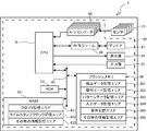
- FIG. 3 is a block diagram showing an electrical configuration of the input device 2.
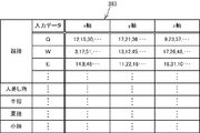
- FIG. It is explanatory drawing of the pattern data memorize
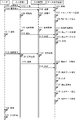
- FIG. It is a timing chart corresponding to a part of main processing of a 1st embodiment.
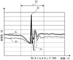
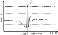
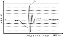
- the detection data (ring finger, z-axis direction) 52 acquired by the input device 2 and the input device 3 It is a graph which illustrates the detection data (ring finger, z-axis direction) 62 to be performed.
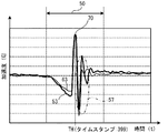
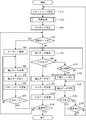
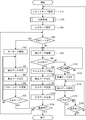
- the detection data (middle finger, z-axis direction) 53 acquired by the input device 2 and the input device 3 It is a graph which illustrates the detection data (middle finger, z-axis direction) 63 to be performed. It is a flowchart of the main process of 1st Embodiment.
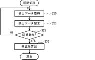
- FIG. 10 is a flowchart of synchronization processing executed in the main processing of FIG. 9.
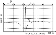
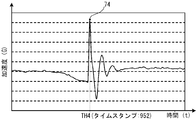
- 11 is a graph illustrating detection data (little finger, z-axis direction) acquired by the input device 2 in the synchronization process of FIG. 10.
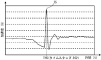
- 11 is a graph illustrating detection data (ringing finger, z-axis direction) acquired by the input device 2 in the synchronization process of FIG. 10.
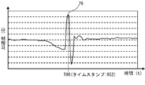
- 11 is a graph illustrating detection data (middle finger, z-axis direction) acquired by the input device 2 in the synchronization process of FIG. 10.
- It is a graph which illustrates the detection data 94 detected in learning mode.
- FIG. 3 is a block diagram showing an electrical configuration of a data determination device 4.
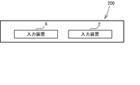
- FIG. It is a timing chart corresponding to a part of main process of 2nd Embodiment. It is a flowchart of the detection process of 2nd Embodiment. It is a flowchart of the main process of 2nd Embodiment. It is a flowchart of the synchronous process performed by the main process of FIG. 22 is a graph illustrating detection data (little finger, z-axis direction) acquired by the input device 6 in the synchronization processing of FIG. 21. 22 is a graph illustrating detection data (ringing finger, z-axis direction) acquired by the input device 6 in the synchronization processing of FIG. 21. 22 is a graph illustrating detection data (middle finger, z-axis direction) acquired by the input device 6 in the synchronization processing of FIG. 21. It is a conceptual diagram of the input system 200 of 3rd Embodiment.
- the input system 1 detects the movement of the user's hand and determines input data.
- the input system 1 of the first embodiment detects an operation of a hand or a finger that presses a virtual keyboard key, and determines input data based on the key corresponding to the operation.
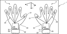
- the input system 1 includes an input device 2 and an input device 3.
- the input device 2 is attached to the user's right hand.
- the input device 3 is attached to the left hand of the user. Since the physical configuration of the input device 2 and the input device 3 is basically the same, the input device 2 will be described as an example.
- the input device 2 includes a glove part 23, a sensor 21, a control part 22, a harness 24, a display part 29, and an input part 31.
- the glove part 23 is a glove for the right hand.
- the sensor 21 is provided corresponding to each finger of the hand to which the input device 2 is attached. Each sensor 21 is attached to the fingertip portion of the surface on the back side of the glove part 23.
- the sensor 21 only needs to have a function of detecting movement of a hand, particularly a finger, and for example, either an acceleration sensor or a gyro sensor is used.
- the sensor 21 of the first embodiment is an acceleration sensor.
- the sensor 21 always outputs an electrical signal indicating acceleration (G) to the control unit 22 for each detection direction when the power of the input device 2 is turned on.
- G electrical signal indicating acceleration
- three directions of the x-axis direction, the y-axis direction, and the z-axis direction are set as axes indicating the detection direction.
- the control unit 22 determines input data based on the electrical signal output from the sensor 21.
- the control unit 22 is attached to the wrist portion on the back side surface of the glove unit 23.
- the control unit 22 is connected to each sensor 21 by a harness 24. A signal output from the sensor 21 is transmitted to the control unit 22 via the harness 24.
- the display unit 29 is disposed on the surface of the control unit 22.
- the display unit 29 is configured by an LED and notifies the user of an operation mode that defines a process to be executed by the input system 1.
- any one of an input mode, a reset mode, a learning mode, and a standby mode is set as an operation mode.
- processing for determining input data is executed based on the electrical signal output from the sensor 21 to the control unit 22.
- the left LED is lit.
- the learning mode a process for updating pattern data stored in a pattern data storage area 383 of the flash memory 38 to be described later is executed.
- the operation mode is set to the learning mode, all the LEDs are turned on.
- the reset mode a synchronization process for eliminating the time stamp clock deviation between the input device 2 and the input device 3 is executed.
- the central LED is turned on.
- the standby mode processing for determining input data based on the electrical signal is not executed.
- the operation mode is set to the standby mode, the right LED is lit.
- the display unit 29 for example, an LCD can be used in addition to the LED.
- the input unit 31 is a button used when the user sets the operation mode of the input system 1.
- the input device 2 includes a control unit 22 and a sensor 21.
- the control unit 22 includes a CPU 41, a ROM 42, a RAM 43, a flash memory 38, an A / D converter 45, an RF module 46, an antenna 47, a display unit 29, an input unit 31, and a bus 44.
- the CPU 41 is connected to each of the ROM 42, the RAM 43, and the flash memory 38 via the bus 44.
- the CPU 41 manages the main control of the input device 2 and executes various calculations and processes related to the determination of input data according to various programs stored in the program storage area of the ROM 42.
- the program may be stored in an external storage device such as a flexible disk.
- the ROM 42 includes a plurality of storage areas including a program storage area and a setting storage area.
- the program storage area stores various programs including a main program for executing various processes in the input system 1, an output program, a detection program, a clock program, and a time stamp clock program.
- the setting storage area initial setting values and parameters of the input device 2 are stored.
- the RAM 43 includes a clock storage area 431, a time stamp clock storage area 432, and other information storage areas 433.
- the clock storage area 431 stores a clock value.
- As the clock value for example, either a count value or a time is used. In the first embodiment, a count value incremented every 100 nsec is used as the clock value.
- the time stamp clock storage area 432 stores a time stamp clock value referred to when a time stamp is added to the electrical signal output from the sensor 21.
- As the time stamp clock value for example, either a count value or a time is used. In the first embodiment, a count value that is incremented every time the clock value stored in the clock storage area 431 is incremented 50 times is used as the time stamp clock value.
- the other information storage area 433 stores the calculation result and the like calculated by the CPU 41.
- the flash memory 38 includes a detection data storage area 381, an operation mode storage area 382, a pattern data storage area 383, an input data storage area 384, a condition storage area 385, and other information storage areas 386.
- the detection data storage area 381 the electrical signal output from the sensor 21 and the time stamp given to the electrical signal are stored as detection data.
- the time stamp included in the detection data indicates a time stamp clock value when the electric signal output from the sensor 21 is acquired by the control unit 22.
- the detection data is stored for each detection condition in which the finger to which the sensor 21 is attached and the detection direction are combined.
- the operation mode storage area 382 stores the operation mode of the input system 1.
- the pattern data storage area 383 the comparison value calculated based on the detection data and the input data are associated with each other and stored as pattern data.
- the input data of this embodiment is a key type of the virtual keyboard. As shown in FIG. 3, the pattern data is stored for each detection condition.
- the input data storage area 384 stores input data determined by comparing the detection data and the pattern data.
- the condition storage area 385 stores various conditions including parameters for executing a main process described later and a synchronization pattern that is a comparison value corresponding to the synchronization operation. Other information is stored in the other information storage area 386.
- the A / D converter 45 converts an electrical signal composed of an analog signal output from the sensor 21 into a digital signal.
- the A / D converter 45 is connected to the sensor 21 and the CPU 41.
- the antenna 47 transmits and receives data between the input device 2 and the external device. In the first embodiment, the antenna 47 wirelessly transmits input data determined by the CPU 41 to an external device such as a PC.
- the RF module 46 is connected between the antenna 47 and the CPU 41 and controls modulation.
- the input apparatus 2 starts various processes when the power of the input apparatus 2 is turned on at the timing T1 in FIG.
- the input device 3 starts various processes when the power of the input device 3 is turned on at the timing T2. Since the processes executed by the input device 2 and the input device 3 are basically the same, the input device 2 will be described as an example.
- the output process, the clock process, the time stamp clock process, the key type acquisition process, the detection process, and the main process are each executed by the CPU 41 in accordance with a program stored in the ROM 42.
- each process is performed by the input apparatus 3 among the timings of the time chart of FIG.
- the execution timing is described in parentheses.
- an electrical signal indicating each acceleration (G) in the x-axis direction, the y-axis direction, and the z-axis direction, which are three types of detection directions, is constantly output from the sensor 21. Is output.
- the clock value stored in the clock storage area 431 is incremented at a predetermined cycle such as 100 nsec, for example, while the input device 2 is powered on.
- the clock storage area 431 is initialized at T3 (T4) timing. In the first embodiment, the initial value of the clock value is 0.
- the time stamp clock value stored in the time stamp clock storage area 432 is incremented by 50 times while the power supply of the input device 2 is turned on. Incremented each time At the start of the time stamp clock process, the time stamp clock storage area 432 is initialized at the timing T3 (T4). In the first embodiment, the initial value of the time stamp clock value is set to zero. When the T3 timing is different from the T4 timing, the input device 2 and the input device 3 have a difference in the clock value and the time stamp clock value incremented based on the clock value.
- the key type acquisition process a process of acquiring the key type output from the keyboard wirelessly connected to the input device 2 is executed during the period when the operation mode of the input system 1 is set to the learning mode. In the key type acquisition process, the acquired key type and the time stamp assigned to the key type are stored in the RAM 43.
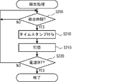
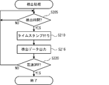
- the electrical signal output in the output process is detected by the CPU 41 at predetermined intervals.
- the clock storage area 431 of the RAM 43 is referred to, and it is determined whether or not it is a detection time (S205).
- the detection time is determined when a predetermined period of time such as 5 msec has elapsed since the previous detection. The predetermined period is stored in the condition storage area 385. If it is not the detection time (S205: No), the process waits until the detection time is reached. When it is the detection time (S205: Yes), the electric signal output from the sensor 21 is acquired, and a time stamp is given to the acquired electric signal (S210).
- the time stamp added to the electric signal is a time stamp clock value stored in the time stamp clock storage area 432 when the electric signal is acquired.
- the electrical signal acquired in S210 and the time stamp given to the electrical signal are stored as detection data in the detection data storage area 381 (S215).
- the detection data is stored for each detection condition. If the power of the input device 2 is ON (S220: No), the process returns to S205, and if the power is OFF (S220: Yes), the detection process ends.
- the input system 1 determines input data based on the detection data stored in S215 of the detection process of FIG.
- the input data includes the key type of the virtual keyboard and a time stamp.
- Each of the input device 2 and the input device 3 outputs input data determined based on the detection data to an external device such as a PC via the antenna 47.
- the external device that has received the input data determines the order of the input data based on the time stamp included in the input data.
- the time stamp is given to each of the input device 2 and the input device 3.
- the operation mode of the input system 1 is the reset mode
- a synchronization process for eliminating a time stamp clock value difference between the input device 2 and the input device 3 is executed.
- the reset mode is automatically set when the power is turned on and when shifting from the standby mode to another mode.
- the synchronization process is executed as follows in the main process.
- the input system 1 detects a timing at which the synchronization operation is executed based on detection data, with an operation in which at least a part of the left and right hands of the user collides such as applause as a synchronization operation.
- the input system 1 sets the time stamp clock value between the input device 2 and the input device 3 to 0.
- the detection data 51 to 53 acquired by the input device 2 and the detection data 61 to 63 acquired by the input device 3 are the same TH timing, respectively.
- a change pattern having a peak 70 is shown in FIG.
- the change in the range 55 to 57 appearing after the peak 70 is a change in acceleration due to the impact after the collision.
- the timing at which the detection data corresponding to the synchronization operation is acquired matches between the input device 2 and the input device 3. Therefore, if the time stamp clock values of the input device 2 and the input device 3 are reset at the timing when the detection data corresponding to the synchronization operation is acquired, the time stamp clocks of the input device 2 and the input device 3 are reset. The deviation can be eliminated.
- the reset mode is set as the operation mode of the input system 1 at the timing T5 (T6) and stored in the operation mode storage area 382 (S10).
- the central LED of the display unit 29 is turned on at T7 (T8) timing. The user visually checks the display unit 29 at T11 timing and confirms that the operation mode of the input system 1 is set to the reset mode.
- Synchronization processing is started at T9 (T12) timing (S15).
- a predetermined number of pieces of detection data stored in the detection data storage area 381 are acquired in the descending order of time stamps and stored in the RAM 43 at the timing illustrated by T10 and T19 (T14 and T20).
- the number of detection data acquired in S20 is stored in the condition storage area 385.
- 100 pieces of detection data are acquired for each detection condition. Assume that the detection data acquired in S20 shows the patterns illustrated in FIGS.
- the detection data acquired in S20 is processed, and the processed detection data is stored in the RAM 43 as a detection pattern (S23).
- S23 for example, five average values are calculated for each detection condition as the feature amount of the detection data.
- the method for calculating the average value will be described using the detection data in the z-axis direction of the little finger shown in FIG. 11 as an example.
- the 100 detection data acquired in S20 are classified according to the period 81 every 100 msec. Each period 81 includes 20 detection data. For each period 81, the average value of the detection data is calculated. In S23, since five average values are calculated for each detection condition, a total of 75 average values are obtained.
- the average value is stored in the RAM 43 for each detection condition.
- S25 it is determined whether or not the user has performed a synchronization operation (S25). Specifically, in S25, if the detection pattern calculated in S23 is a synchronization pattern, it is determined that the user has performed a synchronization operation. That is, in S25, if it is determined that the detection data acquired in S20 is a synchronization signal, the average value calculated in S23 and the synchronization pattern stored in the condition storage area 385 for each detection condition. To be compared. When the degree of difference between the detection pattern and the synchronization pattern is less than the threshold value, it is determined that the detection pattern calculated in S23 is a synchronization pattern related to the synchronization operation (S25: Yes). The threshold value is stored in the condition storage area 385 in advance.
- the process returns to S20.
- the time stamp clock value is set to 0 at T25 (T26) timing and stored in the time stamp clock storage area 432 (S35).
- T25 timing is almost equal to the T26 timing.
- the input mode is set as the operation mode of the input system 1 and stored in the operation mode storage area 382 (S40).
- the left LED of the display unit 29 is turned on at the timing T29 (T30). It is determined whether or not the operation mode of the input system 1 is set to the learning mode (S45). In the learning mode, processing for updating data in the pattern data storage area 383 is executed. When the user operates the input unit 31 to input an instruction, the learning mode is set as the operation mode.
- the processing in the learning mode is executed.
- the input system 1 and a keyboard outside the input system 1 are wirelessly connected (S50).
- the user sequentially presses keys on the keyboard. For example, as shown in FIG. 14, when the user performs an operation 91 of pressing the key corresponding to “J” with the index finger of the right hand, the keyboard sets the key type “J” corresponding to the pressed key to the input device. 2 and the input device 3.
- the key type is acquired by the key type acquisition process and stored in the RAM 43 together with the time stamp.
- detection data is acquired (S55), and the acquired detection data is processed (S60).
- 100 detection data 94 within the detection period 92 are acquired for the detection data in the z-axis direction of the index finger in FIG.
- 100 detection data 94 are classified according to the period 95, and five average values are calculated as comparison values for each period 95.
- the key type “J” stored in the RAM 43 is acquired.
- the comparison value associated with the key type “J” is determined based on the time stamp assigned to the key type “J” and the time stamp of the comparison value.
- the time stamp of the comparison value may be appropriately determined based on 100 detection data used in the process of calculating the comparison value. For the time stamp of the comparison value, for example, an average value of time stamps included in each of 100 pieces of detection data is used.
- the key type and the comparison value are associated with each other and stored as pattern data in the pattern data storage area 383 (S65). It is determined whether or not the input mode is set as the operation mode (S70). When the user operates the input unit 31 to input an instruction, the input mode is set as the operation mode. When the input mode is not set as the operation mode (S70: No), the process returns to S55. When the input mode is set as the operation mode (S70: Yes), processing in the input mode is executed.
- the operation mode is the input mode (S45: No or S70: Yes)
- the user visually checks the LED of the display unit 29 at the T31 timing, confirms the operation mode, and then starts the input operation at the T32 timing.
- detection data is acquired (S75).
- S75 is the same process as S20.
- S80 Based on the detection data acquired in S75, it is determined whether or not an input operation has been executed (S80). If the detection data acquired in S75 has changed by a predetermined amount or more, it is determined that the input operation has been executed.
- the predetermined amount in S80 is appropriately determined in consideration of the amount of change in the detected data when the input operation is performed, and is stored in the condition storage area 385.
- the detection data acquired in S75 is processed (S90).
- the input data corresponding to the detection pattern calculated in S90 is determined and stored in the input data storage area 384 (S95).
- S95 the detection pattern (average value) calculated in S90 and the pattern data stored in the pattern data storage area 383 are sequentially compared for each detection condition.
- the input data includes a time stamp and a key type.
- S95 for example, when the degree of difference between the detection pattern (average value) and the pattern data (comparison value) is less than the threshold, the key type included in the pattern data and the time stamp of the detection pattern are displayed. Determine as input data.
- the threshold value is stored in the condition storage area 385 in advance.
- the time stamp of the detection pattern may be determined as appropriate based on 100 detection data used in the process of calculating the detection pattern. As the time stamp of the detection pattern, for example, an average value of time stamps included in each of 100 detection data is used.
- the input data is transmitted to an external device such as a PC via the antenna 47 (S100).
- the external device that has received the input data determines that the input data has been input in ascending order of the time stamp included in the input data. If the input device 2 is not turned off (S105: No), the process returns to S45. When the power of the input device 2 is turned off (S105: Yes), the main process ends.
- S80 when the input operation is not executed (S80: No), the count value P for counting the period during which the input operation is not executed is incremented and stored in the RAM 43. Next, it is determined whether the count value P is larger than a predetermined value (S110).
- the process of S110 is a process of setting the operation mode of the input system 1 to the standby mode when the input operation is not executed for a predetermined period.
- the predetermined value of S110 is appropriately determined in consideration of the time interval at which the input operation is performed, and is stored in the condition storage area 385. If the count value P is not greater than the predetermined value (S110: No), the process returns to S75.
- the standby mode is set as the operation mode, stored in the operation mode storage area 382 (S115), and the detection data is acquired (S120). Based on the detection data acquired in S120, it is determined whether or not an input operation has been executed (S125). If the input operation has not been executed (S125: No), it is determined whether or not an instruction to set the reset mode has been acquired (S130). The instruction is input to the control unit 22 by operating the input unit 31 by the user. When the instruction has not been acquired (S130: No), the process returns to S120. When an input operation is executed in S125 (S125: Yes), or when an instruction is acquired in S130 (S130: Yes), the process returns to S10. Thus, when the input system 1 is shifted from the standby mode to another mode, the input system 1 sets the reset mode as the operation mode of the input system 1.
- one of the input device 2 and the input device 3 corresponds to the first input device of the present invention, and the other corresponds to the second input device of the present invention.
- the time stamp clock storage area 432 of the RAM 43 that stores the time stamp clock value corresponds to the time stamp clock of the present invention.
- the output process corresponds to the output process of the present invention, and the A / D converter 45 that outputs an electrical signal to the CPU 41 in the output process functions as the output means of the present invention.
- the flash memory 38 corresponds to the storage means of the present invention.
- S75 of the main process in FIG. 9 corresponds to the pattern acquisition process of the present invention, and the CPU 41 that acquires the pattern data stored in the pattern data storage area 383 in S75 functions as the pattern acquisition means of the present invention.
- S95 corresponds to the determination step of the present invention.
- the CPU 41 that compares the detection pattern with the pattern data and determines the key type corresponding to the detection data functions as the determination means of the present invention.
- the detection process S210 in FIG. 5 corresponds to the time stamp assigning step of the present invention.
- the CPU 41 that assigns a time stamp to the electric signal functions as a time stamp assigning unit of the present invention.
- S10 corresponds to the reset mode setting step of the present invention.
- the CPU 41 that sets the operation mode of the input system 1 to the reset mode functions as the reset mode setting means of the present invention.
- the CPU 41 that sets the operation mode of the input system 1 to the standby mode functions as standby mode setting means of the present invention.
- the CPU 41 that executes the process of S125 or S130 functions as an instruction acquisition unit of the present invention.
- S25 in FIG. 10 corresponds to the signal acquisition process of the present invention, and the CPU 41 using the detection data satisfying the condition of S25 as a synchronization signal functions as the signal acquisition means of the present invention.
- S35 corresponds to the synchronization step of the present invention, and the CPU 41 that resets the time stamp clock value in the time stamp clock storage area 432 in S35 functions as the synchronization means of the present invention.
- S40 corresponds to the input mode setting step of the present invention. In S40, the CPU 41 that sets the operation mode of the input system 1 to the input mode functions as the input mode setting means of the present invention.
- the synchronization process (S15) is executed when the operation mode of the input system 1 is set to the reset mode.
- the time stamp clock difference between the input device 2 and the input device 3 is eliminated by resetting the time stamp clock value in the time stamp clock storage area 432 in S ⁇ b> 35. For this reason, the input system 1 can input the input data in the order instructed by the user's hand movement.
- the synchronization process (S15) is executed only when the operation mode of the input system 1 is set to the reset mode. For this reason, the input system 1 can avoid that a synchronous process is performed at the timing which a user does not intend.
- the input system 1 when the power is turned on, the operation mode of the input system 1 is set to the reset mode, and the synchronization process is executed. Therefore, the input system 1 can input the input data in the order instructed by the user's hand movement from the start of input. Further, in the input system 1, the synchronization process is executed when the input mode is set from the standby mode. Therefore, in the input system 1, even when the time stamp clock is shifted between the input device 2 and the input device 3 in the standby mode, the shift can be corrected by the synchronization process. Further, in the input system 1, when it is determined that the user has moved the left and right hands simultaneously based on the detection data, the detection data is acquired as a synchronization signal. Therefore, the user can issue an instruction to cause the input system 1 to execute the synchronization process with a simple operation of simultaneously moving left and right hands such as applause.
- the time stamp clock values of the input device 2 and the input device 3 are reset at the timing when the detection data corresponding to the synchronous operation is acquired.
- the difference between the time stamp clocks of the two input devices included in the input system is eliminated. May be.
- the input system 100 of the second embodiment will be described.
- symbol is provided about the structure similar to 1st Embodiment.
- the input system 100 detects an operation of a user's hand pressing a virtual keyboard key, and determines input data based on the key corresponding to the operation.
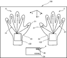
- the input system 100 includes an input device 5, an input device 6, and a data determination device 4.
- the input device 5 includes a glove part 23, a sensor 21, and a harness 24 similar to those in the first embodiment.
- the input device 6 includes a glove part 33, a sensor 21, and a harness 24.
- Each of the input device 5 and the input device 6 includes a control unit 122, and the control unit 122 is different from the control unit 22 of the first embodiment in electrical configuration, as will be described later.
- the data determination device 4 includes a display unit 39 and an input unit 40.
- the display unit 39 displays the operation mode of the input system 100 in the same manner as the display unit 29 of the first embodiment.
- the input unit 40 is a button used when the user sets the operation mode of the input system 100.
- the input device 5 includes a control unit 122 and a sensor 21.
- the control unit 122 includes the same CPU 41, ROM 42, RAM 43, A / D converter 45, RF module 46, antenna 47, and bus 44 as in the first embodiment.
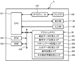
- the data determination device 4 includes a CPU 101, a ROM 102, a RAM 103, a flash memory 38, an RF module 105, an antenna 106, a display unit 39, and an input unit 40 as shown in FIG.
- the CPU 101 is connected to the ROM 102, the RAM 103, the flash memory 38, and the bus 104.
- the CPU 101 is in charge of main control of the data determination device 4 and executes various calculations and processes related to determination of input data according to various programs stored in the program storage area of the ROM 102.
- the program may be stored in an external storage device such as a flexible disk.
- the ROM 102 includes a plurality of storage areas including a program storage area and a setting storage area. Various programs including a main program and an acquisition program are stored in the program storage area. Initial setting information and parameters are stored in the setting storage area.
- the RAM 103 stores calculation results and the like calculated by the CPU 41.
- the flash memory 38 is the same as the input device 2 and the input device 3 of the first embodiment.
- the detection data storage area 381 stores detection data acquired in an acquisition process described later.
- the antenna 106 transmits and receives data wirelessly between the data determination device 4 and the external device.
- the external device includes an input device 5, an input device 6, and an external device such as a PC that is an output destination of input data.
- the RF module 105 is connected to the CPU 101 and the antenna 106 and manages modulation / demodulation control.
- the display unit 39 is connected to the CPU 101 and is controlled by the CPU 101.
- the input unit 40 is connected to the CPU 101 and inputs instructions to the CPU 101.
- the process executed by the input system 100 will be described.
- the main process shown in FIG. 9 is not executed in each of the input device 5 and the input device 6.
- the input device 5 starts processing when the power of the input device 5 is turned on at T101 timing in FIG.
- the input device 5 transmits a start instruction to the data determination device 4 at T102 timing.
- the input device 6 starts processing when the power of the input device 6 is turned on at T104 timing.
- the input device 6 transmits a start instruction to the data determination device 4 at T105 timing. Since the processes executed by the input device 5 and the input device 6 are basically the same, the input device 5 will be described as an example.
- each of the input device 5 and the input device 6 is executed by the CPU 41 in FIG. 16 according to the program stored in the ROM 42.
- the timing at which each process is executed by the input device 6 is described in parentheses.
- Output processing, clock processing, and time stamp clock processing are basically the same as those in the first embodiment.
- the clock value is set to 0 at the start of processing at the timing of T106 (T108) and stored in the clock storage area 431.
- the time stamp clock process the time stamp clock value is set to 0 at the start of the process at the timing of T106 (T108) and stored in the time stamp clock storage area 432.
- the detection process the electrical signal output in the output process is acquired at predetermined intervals by the CPU 41 included in the control unit 122. 19, when the same processing as the detection processing of the first embodiment shown in FIG. 5 is executed, the same reference numerals are given and the description thereof is omitted.
- the detection process of the second embodiment is different from the detection process of the first embodiment in that S216 is executed instead of S215.
- the electrical signal (S205) acquired at the timing exemplified in T110 and T120 (T110 and T121) and the time stamp given in S210 are exemplified as detection data in T114 and T123 (T115 and T124).
- the data is output to the data determination device 4 at the timing (S216).
- detection data is output from the input device 5 at a predetermined cycle such as 5 msec.
- the data determination device 4 acquires the start instruction transmitted from the input device 5 or the input device 6, the data determination device 4 starts at the timing of T ⁇ b> 103.
- the data determination device 4 starts a plurality of processes including an acquisition process and a main process after activation. In the acquisition process, detection data output from the input device 5 or the input device 6 is received, and the received detection data is stored in the detection data storage area 381.
- the reset mode is set as the operation mode of the input system 100 at the timing of T107 in FIG. 18, and is stored in the operation mode storage area 382 (S10).
- the central LED of the display unit 39 is turned on at timing T109. The user visually checks the display unit 39 at T117 timing and confirms that the operation mode of the input system 1 is set to the reset mode.
- Synchronization processing is started at T112 timing (S16).
- detection data is acquired at the timing illustrated by T113 and T122 (S20).
- 100 pieces of detection data are acquired for each detection condition for the detection data acquired from each of the input device 5 and the input device 6. It is assumed that the detection data acquired in S20 shows the patterns illustrated in FIGS. 11 to 13 and FIGS. 22 to 24.
- the detection data acquired in S20 is processed (S23).
- the detection pattern calculated in S23 is compared with the synchronization pattern stored in the condition storage area 385, and it is determined whether or not the synchronization operation has been executed (S25).
- a detection pattern calculated based on detection data acquired from the input device 5 and the input device 6 is a comparison target.
- the difference between the time stamps is a predetermined value such as a value 100 corresponding to 500 msec, for example. When the value is equal to or greater than the value, it is determined that the detected data is not detected when the user performs a synchronous operation.
- the time stamp of the detection pattern of each input device when determining whether or not the synchronization operation is performed is, for example, When the variation of the peak time stamp is within a predetermined allowable value, the average value may be used as the time stamp of the detection pattern of the input device 5.
- the variation in the time stamps of the peaks of each finger is not within a predetermined allowable value, it may be determined that the detection data acquired in S20 is not a synchronization signal.
- the allowable value is preferably determined based on variations in time stamps of the peak of each finger when the user actually performs a synchronization operation.
- the process returns to S20.
- the detection data acquired in S20 is a synchronization signal indicating detection data when the user performs a synchronization operation (S25: Yes)
- the time stamp clock of the input device 5 and the input device 6 at T127 timing.
- a correction amount for eliminating the deviation from the time stamp clock is calculated (S36).
- S ⁇ b> 36 the time stamp clock shift between the input device 5 and the input device 6 is first calculated as a correction amount and stored in the condition storage area 385.
- the correction amount calculation method will be described by taking as an example the case where the detection data acquired in S20 shows the patterns illustrated in FIG. 11 to FIG. 13 and FIG. 22 to FIG.
- a collision timing that is a timing at which the left and right hands collide by a synchronous operation such as applause is calculated.
- the collision timing of the right hand is calculated.
- the right-hand collision timing is, for example, the average value of the collision timing for each detection condition output from the input device 5. Note that the variation in the collision timing is within the above-mentioned predetermined allowable value.
- the peak 71 of the detection data is specified, and the TH1 timing (time stamp: 932) is specified as the collision timing of the peak 71.
- the TH2 timing time stamp: 932 is specified as the collision timing of the peak 72.
- the TH3 timing (time stamp: 932) is specified as the collision timing of the peak 73. Based on the detection data output from the input device 6, the collision timing of the left hand is calculated.
- the TH4 timing (time stamp: 952) is specified as the collision timing of the peak 74.
- the TH5 timing (time stamp: 952) is specified as the collision timing of the peak 75.
- the TH6 timing (time stamp: 952) is specified as the collision timing of the peak 76.
- the difference 20 between the two time stamps is calculated as a correction amount and stored in the condition storage area 385. The The correction amount is referred to in S90 described later.
- the operation mode of the input system 1 is set to the input mode and stored in the operation mode storage area 382 (S40).
- the left LED of the display unit 39 is lit at the timing T129. It is determined whether or not the operation mode is set to the learning mode (S45). Since the process in the learning mode is the same as the main process of the first embodiment, the description thereof is omitted.
- the input mode is set as the operation mode (S45: No or S70: Yes)
- the user visually checks the LED of the display unit 39 at T130 timing, confirms the operation mode, and then inputs at T131 timing.
- Start operation In the input system 100, the same processes of S75 and S80 as in the first embodiment are executed.
- S80 S80: Yes
- the time stamp of the detection data acquired in S75 is corrected and stored in the detection data storage area 381 (S85).
- the correction amount 20 calculated in S36 is added to the time stamp of the detection data output from the input device 5.
- the time stamp of the detection data output from the input device 6 may be reduced by the correction amount 20 calculated in S36.
- the same processing from S90 to S130 as in the first embodiment is executed.
- the data determination device 4 executes the main process.
- one of the input device 5 and the input device 6 corresponds to the first input device of the present invention, and the other corresponds to the second input device of the present invention.
- the time stamp clock storage area 432 of the RAM 43 corresponds to the time stamp clock of the present invention.
- S216 in FIG. 19 corresponds to the output process of the present invention.
- the CPU 41 that outputs an electrical signal to the data determination device 4 functions as the output means of the present invention.
- S95 corresponds to the determining step of the present invention
- the CPU 101 that determines the key type corresponding to the detected data by comparing the detected pattern with the pattern data in S95 functions as the determining means of the present invention.
- S210 of the detection process in FIG. 19 corresponds to the time stamp assigning step of the present invention, and the CPU 41 that assigns the time stamp in S210 functions as a time stamp assigning unit of the present invention.
- 20 corresponds to the reset mode setting step of the present invention, and the CPU 101 that sets the operation mode of the input system 100 to the reset mode in S10 functions as the reset mode setting means of the present invention.
- the CPU 101 that sets the operation mode of the input system 100 to the standby mode functions as standby mode setting means of the present invention.
- the CPU 101 that executes the process of S125 or S130 functions as an instruction acquisition unit of the present invention.
- 21 corresponds to the signal acquisition process of the present invention.
- the CPU 101 using the detection data corresponding to the synchronization operation as a synchronization signal functions as a signal acquisition unit of the present invention.
- S36 corresponds to the synchronization step of the present invention.
- the CPU 101 that calculates the correction amount functions as the synchronization means of the present invention.
- 20 corresponds to the input mode setting step of the present invention, and the CPU 101 that sets the operation mode of the input system 100 to the input mode in S40 functions as the input mode setting means of the present invention.
- the synchronization process (S16) is executed when the operation mode of the input system 100 is set to the reset mode.
- the data determination device 4 calculates the time stamp clock shift between the input device 5 and the input device 6 as a correction amount.
- the data determination device 4 corrects the time stamp so as to eliminate the time stamp clock shift using the correction amount calculated in S36. For this reason, the input system 100 can accurately determine the order of the input data based on the time stamp included in the input data, so that the input data can be input in the order instructed by the user's hand movement. .
- Other effects are the same as those of the input system 1 of the first embodiment.
- An input system 200 according to the third embodiment includes an input device 2 and an input device 6 as shown in FIG. Since the input device 2 is the same as that of the first embodiment, and the input device 6 is the same as that of the second embodiment, the description of the physical configuration and the electrical configuration is omitted.
- the same output processing, clock processing, time stamp clock processing, and detection processing as in the second embodiment are executed.
- detection data is output to the input device 2 in S216 of FIG.
- a plurality of processes including an output process, a clock process, a time stamp clock process, a detection process, an acquisition process, and a main process, similar to the first embodiment or the second embodiment. Is executed.
- Detection data is acquired based on the electrical signal output from the sensor 21 included in the input device 2 by the output process, the clock process, the time stamp clock process, and the detection process.
- the detection data output from the input device 6 is stored in the detection data storage area 381.
- the same process as the main process of the second embodiment of FIG. 20 is executed, and the input data is determined based on the detection data detected in the input device 2 and the detection data output from the input device 6.
- the correspondence between the input system 200 of the third embodiment and the present invention is the same as that of the input system 1 of the first embodiment or the input system 100 of the second embodiment. According to the input system 200 of the third embodiment, the same effects as those of the second embodiment can be obtained.
- the operation of inputting a key of the virtual keyboard is detected and the key type is specified as the input data.
- the present invention is not limited to this.
- the input system stores the correspondence between the hand movement detected by the input system and the input data in the storage means in advance, and based on the detection data corresponding to the movement other than the operation of inputting the key of the virtual keyboard, It is possible to determine.
- the method by which the input system determines the input data based on the detection data can be changed as appropriate. For example, in the main process of FIG. 9 or FIG. 20, a predetermined number of detection data such as 100 is acquired in S75. In S90, the feature amount of the detection data acquired in S75 is calculated. Examples of the feature amount include a variance value and an amplitude. In S95, the feature amount calculated in S90 and the pattern data may be compared to determine input data corresponding to the detection data. The pattern data is a feature amount previously associated with the input data. In the input system of the above embodiment, the detection data for each detection condition is determined by comparing each detection pattern with the comparison value to determine the input data, but the detection data for the specific detection condition, the comparison value, The input data may be determined by comparing.
- the time stamp may be in any form that can determine the input order.
- the time stamp clock value is initialized when the time stamp clock value is initialized.
- the stamp clock value is set to 0, the present invention is not limited to this.
- the current time may be set in the time stamp clock value with reference to the clock. The period for incrementing the time stamp clock value can be changed as appropriate.
- a time stamp is given to the electrical signal output from the sensor 21 in S210 of the detection process of FIG.
- the time stamp may be given to the input data determined in S95 of FIG.
- the time stamp clock of the input device 5 and the input device 6 is corrected by correcting the time stamp in S85 of the main process in FIG. The deviation was resolved.
- the correction amount may be transmitted to either the input device 5 or the input device 6 to correct the time stamp clock of the destination input device. . More specifically, it is assumed that the difference 20 is calculated as the correction amount in S36 of the second embodiment.
- the data determination device 4 transmits the calculated correction amount 20 to the input device 5.
- the input device 5 that has received the correction amount adds the correction amount 20 to the time stamp clock value and stores it in the time stamp clock storage area 432.
- the input system 100 can correct the time stamp clock by using the correction amount, thereby eliminating the time stamp clock shift between the input device 5 and the input device 6.
- the correction amount may be transmitted to the input device 6 or may be transmitted to both the input device 5 and the input device 6. May be. This modification can also be applied to the third embodiment.
- the operation mode is set to the reset mode after the power is turned on or when the operation mode shifts from the standby mode to another mode.
- the present invention is not limited to this.
- the operation mode may be set to the reset mode at the timing when the user operates the input unit 31 to input an instruction. In this way, it is possible to cause the input system to execute the synchronization process at a timing intended by the user, such as when the time stamp clock is shifted between the first input device and the second input device.
- applause is a synchronous operation, but the present invention is not limited to this.
- at least one of the operation of overlapping a part of the right hand and the left hand and the operation of overlapping the back of the right hand and the back of the left hand may be a synchronous operation.
- the method for detecting the synchronization operation based on the detection data can be appropriately changed according to the synchronization operation. For example, when the operation of overlapping the right index finger and the index finger of the left hand is a synchronous operation, when the detection data of the sensor 21 attached to the index finger of each hand changes by a predetermined amount or more, the detection data is a synchronization signal. You may get as
- the input device 2 transmits / receives detection data to / from the input device 3, and acquires each detection data of the input device 2 and the input device 3 as a synchronization signal as in S25 of FIG. Also good. In this way, the input system 1 can distinguish between the synchronous operation and other operations in S25 of FIG.
- the detection data output from the input device 5 and the input device 6 indicate a synchronization pattern and the time stamp difference is equal to or smaller than a predetermined value
- the detection data is stored. It was acquired as a signal for synchronization.
- it is assumed that an operation other than the synchronous operation is not executed when the reset mode is executed, it is not necessary to determine whether or not the time stamp difference is equal to or smaller than a predetermined value.
- Conditions for setting the standby mode as the operation mode of the input system or conditions for shifting the operation mode from the standby mode to another mode can be changed as appropriate.
- a case where the user inputs an instruction by operating the input unit 31 may be set as a condition for setting the operation mode of the input system to the standby mode.
- movement may be set as conditions on which operation mode transfers to other modes from standby mode. In this way, the user can input an instruction to shift from the standby mode to another mode to the input system by executing a predetermined operation.
- the configuration of the input device included in the input system can be changed as appropriate.
- the type of sensor included in the input device, the sensor mounting position, and the number of sensors can be changed as appropriate.
- an acceleration sensor may be installed at the fingertip of each finger and the third joint of each finger as a sensor of the input device.
- the input device may not include the display unit and the input unit.
Landscapes
- Engineering & Computer Science (AREA)
- General Engineering & Computer Science (AREA)
- Theoretical Computer Science (AREA)
- Human Computer Interaction (AREA)
- Physics & Mathematics (AREA)
- General Physics & Mathematics (AREA)
- User Interface Of Digital Computer (AREA)
Abstract
ユーザが手の動きで指示した順序でデータの入力が可能な入力システム、入力装置及び入力方法を提供する。第1の入力装置と、第2の入力装置とを備え、手の動きを示す検出データに応じた入力データを決定する入力システムにおいて、入力システムの動作モードがリセットモードに設定されている場合に、同期処理が実行される。同期処理では、第1の入力装置から出力された検出データと、第2の入力装置から出力された検出データとが同期用信号として取得される(S25:Yes)。同期用信号が取得された場合に、タイムスタンプクロックを補正する処理と、タイムスタンプ付与手段によって付与されるタイムスタンプを補正する補正量を算出する処理との少なくとも一方によって同期処理が実行される(S35)。
Description
本発明は、ユーザの手の動きを示す検出データに基づいて、入力データを決定する入力システム、入力装置及び入力方法に関する。
従来、ユーザがキーボードを使用せずにデータを入力するための入力装置が知られている。例えば特許文献1には、手の仕草によってデータを入力することが可能なデータ入力デバイスが提案されている。データ入力デバイスでは、ユーザの指に取り付けられたセンサから経時的に出力されるデータが、所定の周期でスキャンされる。所定時間内に取得されたスキャンデータが解析され、指の動きが認識される。認識された指の動きに対応する情報が入力されたと判断される。
左手側に取り付けられたセンサと、右手側に取り付けられたセンサとが、データを出力する時刻を示すためにそれぞれタイムスタンプクロックを備える。しかしながら、両タイムスタンプクロックが異なる時刻を示す数値を示している場合には、データ入力デバイスは、ユーザが意図した順序でデータを認識することができないという問題があった。
本発明は上述の問題点を解決するためになされたものであり、ユーザが手の動きで指示した順序でデータの入力が可能な入力システム、入力装置及び入力方法を提供することを目的とする。
上記目的を達成するために、請求項1に係る発明の入力システムは、手に取り付けられ、当該手の動きに応じた電気信号を発生するセンサと、前記センサによって発生された前記電気信号を含む検出データを出力する出力手段とを備えた入力装置と、記憶手段を参照して、前記センサが取り付けられた前記手が所定の動きをした場合に出力される前記検出データのパターンと、所定の入力データとを対応付けて取得するパターン取得手段と、前記出力手段によって出力された前記検出データと、前記パターン取得手段によって取得された前記パターンとの比較結果に基づいて、前記検出データに対応する前記入力データを決定する決定手段と、前記センサによって発生された前記電気信号及び前記決定手段によって決定された前記入力データの少なくともいずれかに対して、前記入力データの入力順序を規定するタイムスタンプを、タイムスタンプクロックを参照して付与するタイムスタンプ付与手段とを備えた入力システムであって、前記決定手段は、前記入力システムで実行される処理を規定する動作モードに応じて、前記検出データに対応する前記入力データを決定する処理を実行し、前記入力システムはさらに、一方の手に取り付けられる前記入力装置である第1の入力装置と、前記一方の手とは異なる他方の手に取り付けられる前記入力装置である第2の入力装置と、前記入力システムの使用状態に応じて、前記入力システムの前記動作モードを、前記第1の入力装置と、前記第2の入力装置との前記タイムスタンプクロックのずれを解消する同期処理を実行させるリセットモードに設定するリセットモード設定手段と、前記入力システムの前記動作モードが前記リセットモードである場合に、前記第1の入力装置から出力された前記検出データと、前記第2の入力装置から出力された前記検出データとを同期用信号として取得する信号取得手段と、前記信号取得手段によって前記同期用信号が取得された場合に、前記タイムスタンプクロックを補正する処理と、前記タイムスタンプ付与手段によって付与される前記タイムスタンプの補正量を求める処理との少なくとも一方を実行することによって前記同期処理を実行する同期手段と、前記同期手段によって、前記同期処理が実行された場合に、前記入力システムの前記動作モードを、前記決定手段によって前記入力データが決定される処理が実行される入力モードに設定する入力モード設定手段とを備えている。
また、請求項2に係る発明の入力システムは、請求項1に記載の発明の構成に加え、前記リセットモード設定手段は、前記入力システムの電源が投入された場合に、前記入力システムの前記動作モードを前記リセットモードに設定することを特徴とする。
また、請求項3に係る発明の入力システムは、請求項1に記載の発明の構成に加え、前記第1の入力装置から出力された前記検出データと、前記第2の入力装置から出力された前記検出データとの少なくともいずれかが、所定期間、所定量以上変化しなかった場合に、前記入力システムの前記動作モードを、前記決定手段によって前記入力データが決定される処理を停止させる待機モードに設定する待機モード設定手段と、前記入力システムの前記動作モードが前記待機モードである場合に、前記入力システムの動作モードを前記リセットモードに設定する指示を取得する指示取得手段とを備え、前記リセットモード設定手段は、前記指示取得手段によって前記指示が取得された場合に、前記入力システムの前記動作モードを前記リセットモードに設定する。
また、請求項4に係る発明の入力システムは、請求項1から3のいずれかに記載の発明の構成に加え、前記信号取得手段は、前記第1の入力装置から出力された前記検出データと、前記第2の入力装置から出力された前記検出データとが、前記第1の入力装置及び前記第2の入力装置が備えるすべての前記センサの前記電気信号が所定期間内に所定の変化をしていることを示す場合に、当該検出データを前記同期用信号として取得する。
また、請求項5に係る発明の入力装置は、手の動きを示す検出データに応じた入力データを決定する入力システムで使用される入力装置であって、一方の手に取り付けられ、当該手の動きに応じた電気信号を発生するセンサと、前記センサによって発生された前記電気信号を含む検出データを出力する出力手段と、記憶手段を参照して、前記センサが取り付けられた前記手が所定の動きをした場合に出力される前記検出データのパターンと、所定の入力データとを対応付けて取得するパターン取得手段と、前記出力手段によって出力された前記検出データと、前記パターン取得手段によって取得された前記パターンとの比較結果に基づいて、前記検出データに対応する前記入力データを決定する決定手段と、前記センサによって発生された前記電気信号及び前記決定手段によって決定された前記入力データの少なくともいずれかに対して、前記入力データの入力順序を規定するタイムスタンプを、タイムスタンプクロックを参照して付与するタイムスタンプ付与手段と、前記出力手段によって出力された前記検出データを同期用信号として取得する信号取得手段と、前記信号取得手段によって前記同期用信号が取得された場合に、前記タイムスタンプクロックを補正する処理と、前記出力手段によって付与される前記タイムスタンプの補正量を求める処理との少なくとも一方を実行することによって同期処理を実行する同期手段とを備えている。
また、請求項6に係る発明の入力装置は、請求項5に記載の発明の構成に加え、前記入力システムの使用状態に応じて、前記入力システムで実行される処理を規定する動作モードを、前記同期処理を実行させるリセットモードに設定するリセットモード設定手段と、前記同期手段によって、前記同期処理が実行された場合に、前記入力システムの前記動作モードを、前記検出データに基づき前記入力データを決定する処理が実行される入力モードに設定する入力モード設定手段とを備え、前記信号取得手段は、前記入力システムの前記動作モードが前記リセットモードに設定されている場合に、前記同期用信号を取得する。
また、請求項7に係る発明の入力方法は、第1の入力装置と、第2の入力装置とを備えた入力システムを使用して、手の動きを示す検出データに応じた入力データをコンピュータが決定する入力方法であって、手に取り付けられたセンサによって発生された、当該手の動きに応じた電気信号を含む検出データを出力する出力工程と、記憶手段を参照して、前記センサが取り付けられた前記手が所定の動きをした場合に出力される前記検出データのパターンと、所定の前記入力データとを対応付けて取得するパターン取得工程と、前記入力システムの動作モードに応じて、前記出力工程において出力された前記検出データと、前記パターン取得工程において取得された前記パターンとの比較結果に基づいて、当前記検出データに対応する前記入力データを決定する決定工程と、前記センサによって発生された前記電気信号及び前記決定工程において決定された前記入力データの少なくともいずれかに対して、前記入力データの入力順序を規定するタイムスタンプを、タイムスタンプクロックを参照して付与するタイムスタンプ付与工程と、前記入力システムの使用状態に応じて、前記入力システムの前記動作モードを、前記第1の入力装置と、前記第2の入力装置との前記タイムスタンプクロック及び前記タイムスタンプの少なくとも一方のずれを解消する同期処理を実行させるリセットモードに設定するリセットモード設定工程と、前記入力システムの前記動作モードが前記リセットモードである場合に、前記第1の入力装置から出力された前記検出データと、前記第2の入力装置から出力された前記検出データとを同期用信号として取得する信号取得工程と、前記信号取得工程において前記同期用信号が取得された場合に、前記タイムスタンプクロックを補正する処理と、前記タイムスタンプ付与手段によって付与される前記タイムスタンプの補正量を求める処理との少なくとも一方を実行することによって、前記同期処理を実行する同期工程と、前記同期工程において、前記同期処理が実行された場合に、前記入力システムの前記動作モードを、前記決定工程において前記入力データを決定する処理が実行される入力モードに設定する入力モード設定工程とを備えている。
請求項1に係る入力システムでは、入力システムの動作モードとしてリセットモードが設定されている場合に、同期用信号が取得される。そして、入力システムは、タイムスタンプクロックを補正する処理と、タイムスタンプ付与手段によって付与されるタイムスタンプを補正する補正量を算出する処理との少なくとも一方によって、第1の入力装置と第2の入力装置とを実質的に同期させる。このため、請求項1に係る入力システムは、ユーザが手の動きで指示した順序で入力データを入力することができる。また、同期処理は、入力システムの動作モードがリセットモードに設定されている場合にのみ実行される。このため、請求項1に係る入力システムは、ユーザが意図しないタイミングで同期処理が実行されることを回避することができる。
また、請求項2に係る入力システムは、電源が入れられた場合に同期処理が実行される。したがって、請求項2に係る入力システムは、請求項1の発明の効果に加え、入力開始時から、ユーザが手の動きで指示した順序で入力データを入力することができる。
また、請求項3に係る入力システムでは、待機モードから入力モードに設定された場合に同期処理が実行される。したがって、請求項3に係る入力システムでは、請求項1の発明の効果に加え、待機モードにおいて、第1の入力装置のタイムスタンプクロックと、第2の入力装置のタイムスタンプクロックとがずれた場合にも、そのずれを補正することができる。
また、請求項4に係る入力システムは、ユーザが左右の手を同時に動かす動作をしたと判断される場合に、同期用信号が取得される。したがって、請求項1から3のいずれかの発明の効果に加え、ユーザは、拍手等の左右の手を同時に動かすという簡単な動作で、入力システムに同期処理を実行させる指示を出すことができる。
また、請求項5に係る入力装置では、同期用信号が取得されて、同期処理が実行される。このため、請求項5の入力装置を備える入力システムでは、ユーザが手の動きで指示した順序で入力データを入力することができる。
また、請求項6に係る入力装置では、入力システムの動作モードがリセットモードに設定されている場合に、同期用信号が取得される。このため、請求項6に係る入力装置は、請求項5の発明の効果に加え、ユーザが意図しないタイミングで同期処理が実行されることを回避することができる。
また、請求項7に係る入力方法では、入力システムの動作モードがリセットモードに設定されている場合に、同期用信号が取得され、同期処理が実行される。このため、請求項7に係る入力方法によれば、ユーザが手の動きで指示した順序で入力データを入力することができる。また同期処理は、入力システムの動作モードがリセットモードに設定されている場合にのみ実行される。このため、請求項7に係る入力方法は、ユーザが意図しないタイミングで同期処理が実行されることを回避することができる。
以下、本発明を具現化した第1と第2の実施形態の入力システム、入力装置及び入力方法について、図面を参照して順に説明する。なお、これらの図面は、本発明が採用しうる技術的特徴を説明するために用いられるものであり、記載されている装置の構成、各種処理のフローチャートなどは、それのみに限定する趣旨ではなく、単なる説明例である。
図1において、入力システム1は、ユーザの手の動きを検出して、入力データを決定する。第1の実施形態の入力システム1は、特に、仮想的なキーボードのキーを押下する手又は指の動作を検出し、動作に対応するキーに基づき入力データを決定する。入力システム1は、入力装置2と入力装置3とを備える。入力装置2は、ユーザの右手に取り付けられる。入力装置3は、ユーザの左手に取り付けられる。入力装置2と、入力装置3との物理的構成は、基本的に同様であるので、入力装置2を例に説明をする。
入力装置2は、手袋部23と、センサ21と、制御部22と、ハーネス24と、表示部29と、入力部31とを備える。
手袋部23は、右手用の手袋である。センサ21は、入力装置2が取り付けられた手の各指に対応して設けられる。各センサ21は、手袋部23の甲側の表面のうち、指先部分に取り付けられている。センサ21は、手、特に指の動作を検出する機能を備えていればよく、例えば、加速度センサと、ジャイロセンサとのいずれかが用いられる。第1の実施形態のセンサ21は、加速度センサである。センサ21は、入力装置2の電源が投入された場合に、検出方向毎に加速度(G)を示す電気信号を常時制御部22に対して出力する。第1の実施形態では検出方向を示す軸として、x軸方向と、y軸方向と、z軸方向との3方向が設定されている。
制御部22は、センサ21から出力された電気信号に基づき入力データを決定する。制御部22は、手袋部23の甲側の表面の手首部分に取り付けられている。制御部22は、ハーネス24によって各センサ21と接続されている。センサ21から出力された信号は、ハーネス24を介して制御部22に伝送される。
表示部29は、制御部22の表面に配置されている。表示部29は、LEDで構成され、入力システム1で実行される処理を規定する動作モードをユーザに通知する。入力システム1では、動作モードとして、入力モードと、リセットモードと、学習モードと、待機モードとのいずれかのモードが設定される。入力モードでは、センサ21から制御部22に出力された電気信号に基づき、入力データを決定する処理が実行される。動作モードとして入力モードが設定されている場合、左のLEDが点灯される。学習モードでは、後述するフラッシュメモリ38のパターンデータ記憶エリア383に記憶されているパターンデータを更新する処理が実行される。動作モードが学習モードに設定されている場合、全てのLEDが点灯される。リセットモードでは、入力装置2と、入力装置3とのタイムスタンプクロックのずれを解消する同期処理が実行される。動作モードがリセットモードに設定されている場合、中央のLEDが点灯される。待機モードでは、電気信号に基づき入力データを決定する処理が実行されない。動作モードが待機モードに設定されている場合、右のLEDが点灯される。なお表示部29としては、LEDの他に、例えばLCDが使用可能である。入力部31は、ユーザが入力システム1の動作モードを設定する際に用いられるボタンである。
入力装置2と、入力装置3との電気的構成は同様であるので、入力装置2を例に説明をする。図2に示すように、入力装置2は、制御部22と、センサ21とを備える。制御部22は、CPU41と、ROM42と、RAM43と、フラッシュメモリ38と、A/Dコンバータ45と、RFモジュール46と、アンテナ47と、表示部29と、入力部31と、バス44とを備える。CPU41は、ROM42と、RAM43と、フラッシュメモリ38とのそれぞれとバス44を介して接続されている。
CPU41は、入力装置2の主制御を司り、ROM42のプログラム記憶エリアに記憶された各種プログラムに従って、入力データの決定に関わる各種演算及び処理を実行する。プログラムはフレキシブルディスク等の外部記憶装置に記憶されていてもよい。
ROM42は、プログラム記憶エリアと、設定記憶エリアとを含む複数の記憶エリアを備える。プログラム記憶エリアには、入力システム1で各種処理を実行するためのメインプログラムと、出力プログラムと、検出プログラムと、クロックプログラムと、タイムスタンプクロックプログラムとを含む各種プログラムが記憶される。設定記憶エリアには、入力装置2の初期設定値と、パラメータとが記憶される。
RAM43は、クロック記憶エリア431と、タイムスタンプクロック記憶エリア432と、その他の情報記憶エリア433とを備える。クロック記憶エリア431は、クロック値を記憶する。クロック値としては、例えば、カウント値と、時刻とのいずれかが用いられる。第1の実施形態では、クロック値として、100nsec毎にインクリメントされるカウント値が用いられる。タイムスタンプクロック記憶エリア432は、センサ21から出力された電気信号にタイムスタンプを付与する際に参照されるタイムスタンプクロック値を記憶する。タイムスタンプクロック値としては、例えば、カウント値と、時刻とのいずれかが用いられる。第1の実施形態では、タイムスタンプクロック値として、クロック記憶エリア431に記憶されたクロック値が50回インクリメントされる毎にインクリメントされるカウント値が用いられる。その他の情報記憶エリア433は、CPU41が演算処理した演算結果等を記憶する。
フラッシュメモリ38は、検出データ記憶エリア381と、動作モード記憶エリア382と、パターンデータ記憶エリア383と、入力データ記憶エリア384と、条件記憶エリア385と、その他の情報記憶エリア386とを備える。検出データ記憶エリア381には、センサ21から出力された電気信号と、電気信号に対して付与されたタイムスタンプとが、検出データとして記憶される。検出データに含まれるタイムスタンプは、センサ21から出力された電気信号が制御部22において取得された際の、タイムスタンプクロック値を示す。検出データは、センサ21が取り付けられている指と、検出方向とを組み合わせた検出条件毎に記憶される。動作モード記憶エリア382には、入力システム1の動作モードが記憶されている。パターンデータ記憶エリア383には、検出データに基づき算出された比較値と、入力データとが対応付けられ、パターンデータとして記憶されている。本実施形態の入力データは、仮想キーボードのキー種別である。図3に示すように、パターンデータは、検出条件毎に記憶される。入力データ記憶エリア384には、検出データと、パターンデータとを比較して決定された入力データが記憶される。条件記憶エリア385には、後述するメイン処理が実行される際のパラメータと、同期動作に対応する比較値である同期パターンとを含む、各種条件が記憶されている。その他の情報記憶エリア386には、その他の情報が記憶されている。
A/Dコンバータ45は、センサ21から出力されるアナログ信号からなる電気信号をデジタル信号に変換する。A/Dコンバータ45は、センサ21と、CPU41とに接続されている。アンテナ47は、入力装置2と外部装置との間でデータを送受信する。第1の実施形態では、アンテナ47は、CPU41によって決定された入力データを無線でPC等の外部装置に送信する。RFモジュール46は、アンテナ47とCPU41との間に接続され、変調制御を司る。
入力システム1で実行される処理について、入力装置2は、図4のT1タイミングで入力装置2の電源がONにされた場合に、各種処理を開始する。同様に、入力装置3は、T2タイミングで入力装置3の電源がONにされた場合に、各種処理を開始する。入力装置2と、入力装置3とで実行される処理は、基本的に同様であるので、入力装置2を例に説明する。出力処理と、クロック処理と、タイムスタンプクロック処理と、キー種別取得処理と、検出処理と、メイン処理とは、それぞれ、ROM42に記憶されたプログラムに従って、CPU41により実行される。以下の説明では、入力装置2で実行される処理と、入力装置3で実行される処理との対応を明確にするため、図4のタイムチャートの各タイミングのうち、入力装置3で各処理が実行されるタイミングを、括弧内に記載する。
出力処理では、入力装置2の電源がONにされている期間、センサ21から3種類の検出方向であるx軸方向、y軸方向、z軸方向の各加速度(G)を示す電気信号が常時出力される。クロック処理では、入力装置2の電源がONにされている期間、クロック記憶エリア431に記憶されているクロック値が、例えば、100nsecなどの所定周期でインクリメントされる。クロック処理開始時には、T3(T4)タイミングでクロック記憶エリア431が初期化される。第1の実施形態では、クロック値の初期値を0とする。タイムスタンプクロック処理では、入力装置2の電源がONにされている期間、タイムスタンプクロック記憶エリア432に記憶されているタイムスタンプクロック値が、クロック記憶エリア431に記憶されたクロック値が50回インクリメントされる毎にインクリメントされる。タイムスタンプクロック処理開始時には、T3(T4)タイミングでタイムスタンプクロック記憶エリア432が初期化される。第1の実施形態では、タイムスタンプクロック値の初期値を0とする。T3タイミングと、T4タイミングとが異なる場合には、入力装置2と入力装置3とで、クロック値及びクロック値に基づきインクリメントされるタイムスタンプクロック値にずれが生じることになる。キー種別取得処理では、入力システム1の動作モードが学習モードに設定されている期間、入力装置2に無線で接続されたキーボードから出力されたキー種別を取得する処理が実行される。キー種別取得処理では、取得されたキー種別と、キー種別に付与されたタイムスタンプとがRAM43に記憶される。
検出処理では、出力処理において出力された電気信号が、CPU41によって所定期間毎に検出される。検出処理では、RAM43のクロック記憶エリア431が参照され、検出時間か否かが判断される(S205)。S205では、前回の検出時から、例えば、5msecなどの所定期間経過している場合に、検出時間であると判断される。所定期間は、条件記憶エリア385に記憶されている。検出時間ではない場合(S205:No)、検出時間に達するまで待機される。検出時間である場合(S205:Yes)、センサ21から出力されている電気信号が取得され、取得された電気信号にタイムスタンプが付与される(S210)。電気信号に付与されるタイムスタンプは、電気信号が取得された際の、タイムスタンプクロック記憶エリア432に記憶されているタイムスタンプクロック値である。S210で取得された電気信号と、電気信号に付与されたタイムスタンプとが、検出データとして検出データ記憶エリア381に記憶される(S215)。検出データは、検出条件毎に記憶される。入力装置2の電源がONの場合は(S220:No)、処理はS205に戻り、電源がOFFの場合は(S220:Yes)、検出処理は終了する。
メイン処理では、入力システム1の動作モードに応じた処理が実行される。メイン処理について、図6から図10を参照して説明する。本実施形態の入力システム1は、メイン処理において、図5の検出処理のS215で記憶された検出データに基づき、入力データを決定する。入力データには、仮想キーボードのキー種別と、タイムスタンプとが含まれる。入力装置2と、入力装置3とはそれぞれ、検出データに基づき決定した入力データを、アンテナ47を介してPC等の外部装置に出力する。入力データを受信した外部装置は、入力データに含まれるタイムスタンプに基づき、入力データの順序を決定する。タイムスタンプは入力装置2と、入力装置3とのそれぞれにおいて付与される。入力装置2と、入力装置3とでタイムスタンプクロック値がずれていると、外部装置において入力データの入力順序を的確に設定することができない。第1の実施形態の入力システム1は、入力システム1の動作モードがリセットモードである場合に、入力装置2と入力装置3とのタイムスタンプクロック値のずれを解消する同期処理が実行される。リセットモードは、電源投入時と、待機モードから他のモードに移行する時とに、自動的に設定される。
第1の実施形態の入力システム1では、メイン処理において、次のように同期処理が実行される。入力システム1は、拍手等のユーザの左右の手の少なくとも一部が衝突する動作を同期動作とし、検出データに基づいて同期動作が実行されたタイミングを検出する。入力システム1は、同期動作が検出された場合、入力装置2と、入力装置3とのタイムスタンプクロック値を0に設定する。図6から図8に例示するように、拍手が実行された場合、入力装置2が取得する検出データ51から53と、入力装置3が取得する検出データ61から63とは、それぞれ、同じTHタイミングにピーク70がある変化パターンを示す。ピーク70の後に現れる範囲55から57の変化は、衝突後の衝撃に起因する加速度の変化である。同期動作に対応する検出データが取得されるタイミングは、入力装置2と、入力装置3とで一致する。このため、同期動作に対応する検出データが取得されたタイミングで、入力装置2と、入力装置3とのタイムスタンプクロック値をリセットすれば、入力装置2と、入力装置3とのタイムスタンプクロックのずれを解消させることができる。
図4及び図9に示すようにメイン処理では、T5(T6)タイミングで入力システム1の動作モードとしてリセットモードが設定され、動作モード記憶エリア382に記憶される(S10)。S10では、T7(T8)タイミングで表示部29の中央のLEDが点灯される。ユーザは、T11タイミングで表示部29を目視し、入力システム1の動作モードがリセットモードに設定されたことを確認する。
T9(T12)タイミングで同期処理が開始される(S15)。図10における同期処理では、T10及びT19(T14及びT20)で例示するタイミングにおいて、検出データ記憶エリア381に記憶されている検出データが、タイムスタンプの大きい順に所定個取得され、RAM43に記憶される(S20)。S20の検出データの取得数は、条件記憶エリア385に記憶されている。第1の実施形態では、検出条件毎に、100個の検出データが取得される。S20で取得された検出データが、図11から図13で例示するパターンを示した場合を想定する。
T13及びT21(T16及びT22)で例示するタイミングにおいて、S20で取得された検出データが加工され、加工された検出データは検出パターンとしてRAM43に記憶される(S23)。S23では、例えば、検出データの特徴量として検出条件毎に5個の平均値が算出される。図11で示す小指のz軸方向の検出データを例に、平均値の算出方法を説明する。S20で取得された100個の検出データが、100msec毎の期間81に応じて分類される。各期間81には、20個の検出データが含まれる。期間81毎に、検出データの平均値が算出される。S23では、検出条件毎に、5個の平均値が算出されるので、合計75個の平均値が得られる。平均値は、検出条件毎にRAM43に記憶される。
T15及びT23(T17及びT24)で例示するタイミングでは、ユーザが同期動作をしたか否かが判断される(S25)。具体的には、S25では、S23で算出された検出パターンが、同期パターンであった場合に、ユーザが同期動作を実行したと判断される。すなわち、S25では、S20で取得された検出データが同期用信号であると判断されると、検出条件毎に、S23で算出された平均値と、条件記憶エリア385に記憶された同期パターンとが比較される。検出パターンと同期パターンとの相違の度合いが閾値未満となっている場合に、S23で算出された検出パターンが、同期動作に関する同期パターンであると判断される(S25:Yes)。閾値は、条件記憶エリア385に予め記憶されている。
ユーザが同期動作をしていない場合(S25:No)、処理はS20に戻る。ユーザが同期動作をした場合(S25:Yes)、T25(T26)タイミングでタイムスタンプクロック値に0が設定され、タイムスタンプクロック記憶エリア432に記憶される(S35)。T25タイミングと、T26タイミングとは、ほぼ等しい。図10に示す同期処理が終了した後に、処理は図9のメイン処理に戻る。
S15の次に、T27(T28)タイミングにおいて、入力システム1の動作モードとして入力モードが設定され、動作モード記憶エリア382に記憶される(S40)。S40では、T29(T30)タイミングにおいて、表示部29の左のLEDが点灯される。入力システム1の動作モードが学習モードに設定されたか否かが判断される(S45)。学習モードでは、パターンデータ記憶エリア383のデータを更新する処理が実行される。ユーザが入力部31を操作して指示を入力した場合に、動作モードとして学習モードが設定される。
動作モードが学習モードである場合(S45:Yes)、学習モード時の処理が実行される。入力システム1と、入力システム1の外部のキーボードとが無線で接続される(S50)。ユーザは、キーボードのキーを順次押下する。例えば、図14のように、ユーザが右手の人差し指で「J」に対応するキーを押下する動作91を実行した場合、キーボードは、押下されたキーに対応するキー種別「J」を、入力装置2及び入力装置3に出力する。キー種別は、キー種別取得処理で取得され、タイムスタンプとともに、RAM43に記憶される。S50の次に、検出データが取得され(S55)、取得された検出データが加工される(S60)。
例えば、S55では、図14の人差し指のz軸方向の検出データについて、検出期間92内の100個の検出データ94が取得される。S60では、100個の検出データ94が期間95に応じて分類され、期間95毎に5個の平均値が比較値として算出される。RAM43に記憶されたキー種別「J」が取得される。キー種別「J」に付与されたタイムスタンプと、比較値のタイムスタンプとに基づき、キー種別「J」と対応付けられる比較値が決定される。比較値のタイムスタンプは、比較値を算出する処理に用いた100個の検出データに基づき適宜定められればよい。比較値のタイムスタンプは、例えば、100個の検出データのそれぞれに含まれるタイムスタンプの平均値が用いられる。キー種別と、比較値とが対応付けられて、パターンデータとして、パターンデータ記憶エリア383に記憶される(S65)。動作モードとして入力モードが設定されたか否かが判断される(S70)。ユーザが入力部31を操作して指示を入力した場合に、動作モードとして入力モードが設定される。動作モードとして入力モードが設定されていない場合(S70:No)、処理はS55に戻る。動作モードとして入力モードが設定された場合(S70:Yes)、入力モード時の処理が実行される。
動作モードが入力モードである場合には(S45:No又はS70:Yes)、ユーザは、T31タイミングで表示部29のLEDを目視して、動作モードを確認した後、T32タイミングで入力動作を開始する。入力システム1では、検出データが取得される(S75)。S75はS20と同様の処理である。S75で取得された検出データに基づき、入力動作が実行されたか否かが判断される(S80)。S75で取得された検出データが、所定量以上変化している場合に、入力動作が実行されたと判断される。S80の所定量は、入力動作を行った場合の検出データの変化量を考慮して適宜定められ、条件記憶エリア385に記憶されている。入力動作が実行されたと判断された場合には(S80:Yes)、S75で取得された検出データが加工される(S90)。
S90で算出された検出パターンに対応する入力データが決定され、入力データ記憶エリア384に記憶される(S95)。S95では、検出条件毎に、S90で算出された検出パターン(平均値)と、パターンデータ記憶エリア383に記憶されたパターンデータとが順次比較される。入力データには、タイムスタンプと、キー種別とが含まれる。S95では、例えば、検出パターン(平均値)とパターンデータ(比較値)との相違の度合いが閾値未満となっている場合に、そのパターンデータに含まれるキー種別と、検出パターンのタイムスタンプとを入力データとして決定する。閾値は、条件記憶エリア385に予め記憶されている。検出パターンのタイムスタンプは、検出パターンを算出する処理に用いた100個の検出データに基づき適宜定められればよい。検出パターンのタイムスタンプは、例えば、100個の検出データのそれぞれに含まれるタイムスタンプの平均値が用いられる。
アンテナ47を介して、入力データがPC等の外部装置に送信される(S100)。入力データを受信した外部装置は、入力データに含まれるタイムスタンプが小さい順に入力データが入力されたと判断する。入力装置2の電源がOFFにされていない場合には(S105:No)、処理はS45に戻る。入力装置2の電源がOFFにされた場合には(S105:Yes)、メイン処理は終了する。
S80において、入力動作が実行されていない場合(S80:No)、入力動作が実行されていない期間をカウントするカウント値Pがインクリメントされ、RAM43に記憶される。次に、カウント値Pが所定値よりも大きいか否かが判断される(S110)。S110の処理は、所定期間入力動作が実行されなかった場合に、入力システム1の動作モードを待機モードに設定する処理である。S110の所定値は、入力動作が実行される時間間隔等を考慮して適宜定められ、条件記憶エリア385に記憶されている。カウント値Pが所定値よりも大きくない場合(S110:No)、処理はS75に戻る。カウント値Pが所定値よりも大きい場合(S110:Yes)、動作モードとして待機モードが設定され、動作モード記憶エリア382に記憶され(S115)、検出データが取得される(S120)。S120で取得された検出データに基づき、入力動作が実行されたか否かが判断される(S125)。入力動作が実行されていない場合には(S125:No)、リセットモードに設定する指示が取得されたか否かが判断される(S130)。指示は、ユーザが入力部31を操作して制御部22に入力する。指示が取得されていない場合(S130:No)、処理はS120に戻る。S125で入力動作が実行された場合(S125:Yes)、又はS130で指示が取得された場合(S130:Yes)、処理はS10に戻る。このように、入力システム1は、待機モードから、別のモードに移行される際には、入力システム1の動作モードとしてリセットモードを設定する。
以上のように、入力装置2と入力装置3とは、一方が本発明の第1の入力装置に相当し、他方が本発明の第2の入力装置に相当する。タイムスタンプクロック値を記憶するRAM43のタイムスタンプクロック記憶エリア432は、本発明のタイムスタンプクロックに相当する。出力処理は、本発明の出力工程に相当し、出力処理でCPU41に対して電気信号を出力するA/Dコンバータ45は、本発明の出力手段として機能する。フラッシュメモリ38は、本発明の記憶手段に相当する。図9のメイン処理のS75は、本発明のパターン取得工程に相当し、S75で、パターンデータ記憶エリア383に記憶されているパターンデータを取得するCPU41は、本発明のパターン取得手段として機能する。S95は、本発明の決定工程に相当し、S95で、検出パターンと、パターンデータとを比較して、検出データに対応するキー種別を決定するCPU41は、本発明の決定手段として機能する。図5の検出処理S210は、本発明のタイムスタンプ付与工程に相当し、S210で、電気信号に対して、タイムスタンプを付与するCPU41は、本発明のタイムスタンプ付与手段として機能する。S10は、本発明のリセットモード設定工程に相当し、S10で、入力システム1の動作モードをリセットモードに設定するCPU41は、本発明のリセットモード設定手段として機能する。S115で、入力システム1の動作モードを、待機モードに設定するCPU41は、本発明の待機モード設定手段として機能する。S125又はS130の処理を実行するCPU41は、本発明の指示取得手段として機能する。図10のS25は、本発明の信号取得工程に相当し、S25の条件を満たす検出データを同期用信号とするCPU41は、本発明の信号取得手段として機能する。S35には、本発明の同期工程に相当し、S35で、タイムスタンプクロック記憶エリア432のタイムスタンプクロック値をリセットするCPU41は本発明の同期手段として機能する。S40は、本発明の入力モード設定工程に相当し、S40で、入力システム1の動作モードを入力モードに設定するCPU41は、本発明の入力モード設定手段として機能する。
第1の実施形態の入力システム1では、入力システム1の動作モードがリセットモードに設定されている場合に、同期処理(S15)が実行される。入力システム1では、S35でタイムスタンプクロック記憶エリア432のタイムスタンプクロック値をリセットすることによって、入力装置2と入力装置3とのタイムスタンプクロックのずれが解消される。このため、入力システム1は、ユーザが手の動きで指示した順序で入力データを入力することができる。また、同期処理(S15)は、入力システム1の動作モードがリセットモードに設定されている場合にのみ実行される。このため、入力システム1は、ユーザが意図しないタイミングで同期処理が実行されることを回避することができる。入力システム1では、電源がONにされた場合に、入力システム1の動作モードがリセットモードに設定され、同期処理が実行される。したがって、入力システム1は、入力開始時から、ユーザが手の動きで指示した順序で入力データを入力することができる。また、入力システム1では、待機モードから入力モードに設定された場合に同期処理が実行される。したがって、入力システム1では、待機モードにおいて、入力装置2と、入力装置3とでタイムスタンプクロックがずれた場合にも、そのずれを同期処理によって補正することができる。また、入力システム1では、検出データに基づきユーザが左右の手を同時に動かす動作をしたと判断される場合に、検出データが同期用信号として取得される。したがって、ユーザは、拍手等の左右の手を同時に動かすという簡単な動作で、入力システム1に同期処理を実行させる指示を出すことができる。
第1の実施形態の入力システム1では、同期動作に対応する検出データが取得されたタイミングで、入力装置2と、入力装置3とのタイムスタンプクロック値をリセットしていた。これに対し、第2の実施形態の入力システム100のように、タイムスタンプクロックに基づき付与されたタイムスタンプを補正することによって、入力システムが備える2つの入力装置のタイムスタンプクロックのずれを解消させてもよい。
以下、第2の実施形態の入力システム100について説明する。入力システム100の構成について、図15から図17では、第1の実施形態と同様の構成については同じ符号を付与している。入力システム100は、第1の実施形態の入力システム1と同様に、仮想的なキーボードのキーを押下するユーザの手の動作を検出し、その動作に対応するキーに基づき入力データを決定する。入力システム100は、入力装置5と、入力装置6と、データ決定装置4とを備える。
入力装置5は、第1の実施形態と同様の、手袋部23と、センサ21と、ハーネス24とを備える。入力装置6は、手袋部33と、センサ21と、ハーネス24とを備える。入力装置5と、入力装置6とはそれぞれ、制御部122を備え、制御部122は、後述するように、第1の実施形態の制御部22と電気的構成について異なる。データ決定装置4は、表示部39と、入力部40とを備える。表示部39は、第1の実施形態の表示部29と同様に、入力システム100の動作モードを表示する。入力部40は、ユーザが入力システム100の動作モードを設定する際に用いられるボタンである。
入力システム100の電気的構成について、入力装置5と、入力装置6とは同様であるので、入力装置5を例に説明する。図16のように、入力装置5は、制御部122と、センサ21とを備える。制御部122は、第1の実施形態と同様のCPU41と、ROM42と、RAM43と、A/Dコンバータ45と、RFモジュール46と、アンテナ47と、バス44とを備える。
データ決定装置4は、図17のように、CPU101と、ROM102と、RAM103と、フラッシュメモリ38と、RFモジュール105と、アンテナ106と、表示部39と、入力部40とを備える。CPU101は、ROM102と、RAM103と、フラッシュメモリ38と、バス104を介して接続されている。
CPU101は、データ決定装置4の主制御を司り、ROM102のプログラム記憶エリアに記憶された各種プログラムに従って、入力データの決定に関わる各種演算及び処理を実行する。なお、プログラムはフレキシブルディスク等の外部記憶装置に記憶されていてもよい。
ROM102は、プログラム記憶エリアと、設定記憶エリアとを含む複数の記憶エリアを備える。プログラム記憶エリアには、メインプログラムと、取得プログラムとを含む各種プログラムが記憶される。設定記憶エリアには、初期設定情報と、パラメータとが記憶される。RAM103は、CPU41が演算処理した演算結果等を記憶する。フラッシュメモリ38は、第1の実施形態の入力装置2及び入力装置3と同様である。検出データ記憶エリア381には、後述する取得処理において取得された検出データが記憶される。
アンテナ106は、データ決定装置4と外部装置との間で、無線でデータの送受信を行う。外部装置には、入力装置5と、入力装置6と、入力データの出力先となるPC等の外部装置とが含まれる。RFモジュール105は、CPU101とアンテナ106とに接続され、変復調制御を司る。表示部39は、CPU101と接続され、CPU101によって制御される。入力部40は、CPU101と接続され、CPU101に指示を入力する。
入力システム100で実行される処理について説明する。第2の実施形態では、入力装置5と、入力装置6とのそれぞれにおいて、図9に示したメイン処理は実行されない。入力装置5は、図18のT101タイミングで入力装置5の電源がONにされた場合に処理を開始する。入力装置5は、電源がONにされた場合に、T102タイミングでデータ決定装置4に開始指示を送信する。同様に、入力装置6は、T104タイミングで入力装置6の電源がONにされた場合に処理を開始する。入力装置6は、電源がONにされた場合に、T105タイミングでデータ決定装置4に開始指示を送信する。入力装置5と、入力装置6とで実行される処理は、基本的に同様であるので、入力装置5を例に説明する。入力装置5と、入力装置6とのそれぞれにおいて、実行される処理は、ROM42に記憶されたプログラムに従って、図16のCPU41により実行される。以下の説明では、第1の実施形態と同様に、図18のタイムチャートの各タイミングのうち、入力装置6で各処理が実行されるタイミングを、括弧内に記載する。
出力処理と、クロック処理と、タイムスタンプクロック処理とは、基本的に第1の実施形態と同様である。第2の実施形態のクロック処理では、T106(T108)タイミングで処理開始時にクロック値に0が設定され、クロック記憶エリア431に記憶される。タイムスタンプクロック処理では、T106(T108)タイミングで処理開始時にタイムスタンプクロック値に0が設定され、タイムスタンプクロック記憶エリア432に記憶される。検出処理では、出力処理において出力された電気信号が、制御部122が備えるCPU41によって所定期間毎に取得される。図19において、図5に示す第1の実施形態の検出処理と同様の処理を実行する場合には、同じ符号を付与し、説明を省略する。
図19のように、第2の実施形態の検出処理は、S215に代えてS216が実行される点で、第1の実施形態の検出処理と異なる。S216では、T110及びT120(T110及びT121)で例示するタイミングで取得された電気信号(S205)と、S210で付与されたタイムスタンプとが検出データとして、T114及びT123(T115及びT124)で例示するタイミングでデータ決定装置4に出力される(S216)。検出処理によって、入力装置5から、例えば、5msecなどの所定周期で検出データが出力される。
データ決定装置4で実行される処理について説明する。データ決定装置4は、入力装置5又は入力装置6から送信された開始指示を取得した場合に、T103タイミングで起動する。データ決定装置4は、起動後、取得処理と、メイン処理とを含む複数の処理を開始する。取得処理では、入力装置5又は入力装置6から出力された検出データが受信され、受信された検出データが検出データ記憶エリア381に記憶される。
図20において、図9に示すメイン処理と同様の処理を実行する場合には、同じ符号を付与している。図21において、図10に示す同期処理と同様の処理を実行する場合には、同じ符号を付与している。図20では、図18のT107タイミングで入力システム100の動作モードとしてリセットモードが設定され、動作モード記憶エリア382に記憶される(S10)。S10では、T109タイミングで表示部39の中央のLEDが点灯される。ユーザは、T117タイミングで表示部39を目視し、入力システム1の動作モードがリセットモードに設定されたことを確認する。
T112タイミングで同期処理が開始される(S16)。同期処理では、図21に示すように、T113及びT122で例示するタイミングにおいて、検出データが取得される(S20)。第2の実施形態では、入力装置5と、入力装置6とのそれぞれから取得された検出データについて、検出条件毎に100個の検出データが取得される。S20で取得された検出データが、図11から図13及び図22から図24で例示するパターンを示したものとする。T116及びT125で例示するタイミングにおいて、S20で取得された検出データが加工される(S23)。
T118及びT126で例示するタイミングにおいて、S23で算出された検出パターンと、条件記憶エリア385に記憶された同期パターンとが比較され、同期動作が実行されたか否かが判断される(S25)。第2の実施形態では、入力装置5と、入力装置6とのそれぞれから取得された検出データに基づき算出された検出パターンが比較の対象となる。第2の実施形態では、入力装置5の検出パターンと、入力装置6の検出パターンのそれぞれが同期パターンと一致した場合でも、各タイムスタンプの差が、例えば、500msecに対応する値100などの所定値以上である場合、ユーザが同期動作をした場合の検出データではないと判断される。各タイムスタンプの差と、所定値とによって、ユーザが左右の手で交互に机をたたく等の動作と、同期動作とを区別することができる。所定値は適宜定められ、条件記憶エリア385に記憶されている。なお、ユーザの各指が完全に同時期に衝突しない場合を考慮し、同期動作であるか否かの判定に際して各入力装置の検出パターンのタイムスタンプは、例えば、入力装置5において、各指のピークのタイムスタンプのバラツキが所定の許容値以内である場合に、その平均値を、入力装置5の検出パターンのタイムスタンプとしてもよい。一方、各指のピークのタイムスタンプのバラツキが所定の許容値以内ではない場合には、S20で取得された検出データは同期用信号ではないと判断されてもよい。許容値は、実際にユーザが同期動作を行った場合の各指のピークのタイムスタンプのバラツキに基づき決定されることが好ましい。
S20で取得された検出データが、ユーザが同期動作をした場合の検出データを示す同期用信号ではない場合には(S25:No)、処理はS20に戻る。S20で取得された検出データが、ユーザが同期動作をした場合の検出データを示す同期用信号である場合には(S25:Yes)、T127タイミングで入力装置5のタイムスタンプクロックと、入力装置6のタイムスタンプクロックとのずれを解消するための補正量が算出される(S36)。S36では、まず入力装置5と入力装置6とのタイムスタンプクロックのずれが補正量として算出され、条件記憶エリア385に記憶される。S20で取得された検出データが、図11から図13及び図22から図24で例示するパターンを示す場合を例に、補正量の算出方法を説明する。
S20で取得された検出データに基づき、拍手などの同期動作によって左右の手が衝突したタイミングである衝突タイミングが算出される。入力装置5から出力された検出データに基づき、右手の衝突タイミングが算出される。右手の衝突タイミングは、例えば、入力装置5から出力された検出条件毎の衝突タイミングの平均値とする。なお、衝突タイミングのバラツキは、上述の所定の許容値以内に収まる。図11では、検出データのピーク71が特定され、ピーク71の衝突タイミングとしてTH1タイミング(タイムスタンプ:932)が特定される。図12では、ピーク72の衝突タイミングとしてTH2タイミング(タイムスタンプ:932)が特定される。図13では、ピーク73の衝突タイミングとしてTH3タイミング(タイムスタンプ:932)が特定される。入力装置6から出力された検出データに基づき、左手の衝突タイミングが算出される。図22では、ピーク74の衝突タイミングとしてTH4タイミング(タイムスタンプ:952)が特定される。図23では、ピーク75の衝突タイミングとしてTH5タイミング(タイムスタンプ:952)が特定される。図24では、ピーク76の衝突タイミングとしてTH6タイミング(タイムスタンプ:952)が特定される。右手の衝突タイミングを示すタイムスタンプが数値932であり、左手の衝突タイミングを示すタイムスタンプが数値952である場合、両者タイムスタンプの差20が、補正量として算出され、条件記憶エリア385に記憶される。補正量は、後述するS90において参照される。図21に示す同期処理が終了した後、処理は図20のメイン処理に戻る。
S16の次に、T128タイミングにおいて、入力システム1の動作モードが入力モードに設定され、動作モード記憶エリア382に記憶される(S40)。S40では、T129タイミングにおいて、表示部39の左のLEDが点灯する。動作モードが学習モードに設定されたか否かが判断される(S45)。学習モード時の処理は、第1の実施形態のメイン処理と同様であるので説明を省略する。
動作モードとして入力モードが設定されている場合には(S45:No又はS70:Yes)、ユーザは、T130タイミングで表示部39のLEDを目視して、動作モードを確認した後、T131タイミングで入力動作を開始する。入力システム100では、第1の実施形態と同様のS75とS80との処理が実行される。S80の次に(S80:Yes)、S75で取得された検出データのタイムスタンプが補正され、検出データ記憶エリア381に記憶される(S85)。具体的には、入力装置5から出力された検出データのタイムスタンプに、S36で算出された補正量20が加えられる。なお、S85では、入力装置6から出力された検出データのタイムスタンプが、S36で算出された補正量20だけ減じられてもよい。次に、第1の実施形態と同様のS90からS130の処理が実行される。
以上のように、データ決定装置4は、メイン処理を実行する。第2の実施形態の入力システム100において、入力装置5と入力装置6とは、一方が本発明の第1の入力装置に相当し、他方が本発明の第2の入力装置に相当する。RAM43のタイムスタンプクロック記憶エリア432は、本発明のタイムスタンプクロックに相当する。図19のS216は、本発明の出力工程に相当し、S19で、データ決定装置4に対して電気信号を出力するCPU41は、本発明の出力手段として機能する。フラッシュメモリ38は、本発明の記憶手段に相当する。図20のメイン処理のS75は、本発明のパターン取得工程に相当し、S75でパターンデータを取得するCPU101は、本発明のパターン取得手段として機能する。S95は本発明の決定工程に相当し、S95で検出パターンと、パターンデータとを比較して、検出データに対応するキー種別を決定するCPU101は、本発明の決定手段として機能する。図19の検出処理のS210は、本発明のタイムスタンプ付与工程に相当し、S210でタイムスタンプを付与するCPU41は、本発明のタイムスタンプ付与手段として機能する。図20のS10は、本発明のリセットモード設定工程に相当し、S10で入力システム100の動作モードをリセットモードに設定するCPU101は、本発明のリセットモード設定手段として機能する。S115で、入力システム100の動作モードを待機モードに設定するCPU101は、本発明の待機モード設定手段として機能する。S125又はS130の処理を実行するCPU101は、本発明の指示取得手段として機能する。図21のS25は、本発明の信号取得工程に相当し、S25で、同期動作に対応する検出データを同期用信号とするCPU101は、本発明の信号取得手段として機能する。S36は、本発明の同期工程に相当し、S36で、補正量を算出するCPU101は本発明の同期手段として機能する。図20のS40は、本発明の入力モード設定工程に相当し、S40で入力システム100の動作モードを、入力モードに設定するCPU101は、本発明の入力モード設定手段として機能する。
以上のように、第2の実施形態の入力システム100では、入力システム100の動作モードがリセットモードに設定されている場合に、同期処理(S16)が実行される。データ決定装置4は、図21のS36において入力装置5と入力装置6とのタイムスタンプクロックのずれを補正量として算出する。データ決定装置4は、S85においてS36で算出した補正量を用いてタイムスタンプクロックのずれを解消するように、タイムスタンプを補正する。このため、入力システム100は、入力データに含まれるタイムスタンプに基づき、入力データの順序を的確に決定することができるので、ユーザが手の動きで指示した順序で入力データを入力することができる。その他の効果は、第1の実施形態の入力システム1と同様である。
第3の実施形態の入力システム200について説明する。第3の実施形態の入力システム200は、図25に示すように、入力装置2と、入力装置6とを備える。入力装置2は、第1の実施形態と同様であり、入力装置6は、第2の実施形態と同様であるので、物理的構成及び電気的構成の説明を省略する。
入力装置6では、第2の実施形態と同様の、出力処理と、クロック処理と、タイムスタンプクロック処理と、検出処理とが実行される。ただし、第3の実施形態の入力装置6の検出処理では、図19のS216において、検出データが入力装置2に対して出力される。入力装置2では、第1の実施形態又は第2の実施形態と同様の、出力処理と、クロック処理と、タイムスタンプクロック処理と、検出処理と、取得処理と、メイン処理とを含む複数の処理が実行される。出力処理と、クロック処理と、タイムスタンプクロック処理と、検出処理とによって、入力装置2が備えるセンサ21から出力された電気信号に基づき検出データが取得される。取得処理では、入力装置6から出力された検出データが、検出データ記憶エリア381に記憶される。メイン処理では、図20の第2の実施形態のメイン処理と同様な処理が実行され、入力装置2において検出された検出データ及び入力装置6から出力された検出データに基づき、入力データが決定される。第3の実施形態の入力システム200と、本発明との対応は、第1の実施形態の入力システム1又は第2の実施形態の入力システム100と同様である。第3の実施形態の入力システム200によれば、第2の実施形態と同様の効果が得られる。
なお、本発明は上記の実施の形態に限定されるものではなく、種々の変更が可能である。例えば、次の(a)から(j)の変形を適宜加えてもよい。
(a)上記実施形態では、仮想キーボードのキーを入力する動作が検出され、入力データとしてキー種別が特定されていたが、これに限定されない。入力システムは、入力システムが検出する手の動作と、入力データとの対応を予め記憶手段に記憶すれば、仮想キーボードのキーを入力する動作以外の動作に対応する検出データに基づき、入力データを決定することが可能である。
(b)入力システムが、検出データに基づき、入力データを決定する方法は、適宜変更可能である。例えば、図9又は図20のメイン処理において、S75で、例えば、100個などの所定個の検出データが取得される。S90で、S75で取得された検出データの、特徴量が算出される。特徴量としては、例えば、分散値と、振幅とがあげられる。S95では、S90で算出された特徴量とパターンデータとが比較されて、検出データに対応する入力データが決定されることとしてもよい。パターンデータは、予め入力データと対応付けられた特徴量である。上記実施形態の入力システムは、各検出条件の検出データについて、検出パターンのそれぞれと、比較値とを比較して入力データを決定していたが、特定の検出条件の検出データと、比較値とを比較して入力データを決定してもよい。
(c)タイムスタンプは、入力順序を決定できる形態であればよい。例えば、上記実施形態では、入力装置2と、入力装置3と、入力装置5と、入力装置6とのそれぞれで実行されるタイムスタンプクロック処理において、タイムスタンプクロック値を初期化する際に、タイムスタンプクロック値に0を設定していたがこれに限定されない。入力システム及び入力装置では、各装置がそれぞれ時刻を示すクロックを備えている場合には、そのクロックを参照して、タイムスタンプクロック値に現在時刻を設定してもよい。タイムスタンプクロック値をインクリメントさせる周期は、適宜変更可能である。
(d)第1の実施形態の入力システム1、入力装置2及び入力装置3では、図5の検出処理のS210において、センサ21から出力された電気信号に対してタイムスタンプが付与されていた。タイムスタンプは、例えば、図9のS95において決定された入力データに対して付与されてもよい。
(e)第2の実施形態の入力システム100及びデータ決定装置4では、図20のメイン処理のS85において、タイムスタンプを補正することによって、入力装置5と、入力装置6とのタイムスタンプクロックのずれを解消していた。タイムスタンプクロックの補正方法としては、例えば、図21のS36において、補正量を、入力装置5及び入力装置6のいずれかに送信し、送信先の入力装置のタイムスタンプクロックを補正してもよい。より具体的には、第2の実施形態のS36で補正量として差20が算出された場合を想定する。データ決定装置4は、算出された補正量20を、入力装置5に送信する。補正量を受信した入力装置5は、補正量20をタイムスタンプクロック値に加え、タイムスタンプクロック記憶エリア432に記憶させる。このように、変形例の入力システム100は、補正量を用いてタイムスタンプクロックを補正することによって、入力装置5と、入力装置6とのタイムスタンプクロックのずれを解消させることができる。なお、データ決定装置4が入力装置5に補正量を送信する場合について説明したが、入力装置6に補正量を送信してもよいし、入力装置5と、入力装置6との双方に送信してもよい。本変形例は、第3の実施形態にも適用可能である。
(f)上記実施形態では、電源がONにされた後、又は動作モードが待機モードから他のモードに移行する際に、動作モードがリセットモードに設定されていたが、これに限定されない。例えば、ユーザが入力部31を操作して指示を入力したタイミングで、動作モードがリセットモードに設定されてもよい。このようにすれば、第1の入力装置と、第2の入力装置とでタイムスタンプクロックがずれている場合等ユーザが意図するタイミングで、同期処理を入力システムに実行させることができる、
(g)上記実施形態の入力システムは、拍手を同期動作としていたが、これに限定されない。例えば、右手と左手との一部を重ね合わせる動作と、右手の甲と左手の甲とを重ねあわせる動作との少なくともいずれかを同期動作としてもよい。また、検出データに基づき、同期動作を検出する方法は、同期動作に応じて適宜変更可能である。例えば、右の人差し指と、左手の人差し指とを重ね合わせる動作を同期動作とする場合、各手の人差し指に取り付けられたセンサ21の検出データが所定量以上変化した場合に、検出データを同期用信号として取得してもよい。
(h)第1の実施形態の入力システム1、入力装置2及び入力装置3では、図10のS25において、自身が備えるセンサ21から取得した検出データのみを同期用信号として取得していたが、これに限定されない。例えば、入力装置2は、検出データを入力装置3との間で送受信し、図21のS25と同様に、入力装置2と、入力装置3とのそれぞれの検出データを同期用信号として取得してもよい。このようにすれば、入力システム1は、図10のS25において、同期動作と、他の動作とを区別することができる。同様に、入力システム100では、入力装置5と、入力装置6とから出力された検出データが、同期パターンを示す場合、かつ、タイムスタンプの差が所定値以下の場合に、それらの検出データを同期用信号として取得していた。しかしリセットモード実行時に同期動作以外の動作が実行されることがないと想定される場合には、タイムスタンプの差が所定値以下であるか否かは判断しなくてもよい。
(i)入力システムの動作モードとして待機モードが設定される条件又は動作モードが待機モードから他のモードに移行される条件は適宜変更可能である。例えば、入力システムの動作モードが待機モードに設定される条件として、ユーザが入力部31を操作して指示を入力した場合が設定されてもよい。また、動作モードが待機モードから他のモードに移行される条件として、ユーザが所定の動作を行った場合の検出データが取得された場合が設定されてもよい。このようにすれば、ユーザは所定の動作を実行することによって、待機モードから他のモードに移行させる指示を入力システムに入力することができる。
(j)入力システムが備える入力装置の構成は適宜変更可能である。例えば、入力装置が備えるセンサの種類と、センサの取り付け位置と、センサの個数とは適宜変更可能である。より具体的には、入力装置のセンサとして、加速度センサを、各指の指先と、各指の第3関節とに設置してもよい。また、入力装置は、表示部と入力部とを備えなくてもよい。
1,100,200 入力システム
2,3,5,6 入力装置
4 データ決定装置
21 センサ
22 制御部
38 フラッシュメモリ
41,101 CPU
42,102 ROM
43,103 RAM
45 A/Dコンバータ
47,106 アンテナ
383 パターンデータ記憶エリア
432 タイムスタンプクロック記憶エリア
2,3,5,6 入力装置
4 データ決定装置
21 センサ
22 制御部
38 フラッシュメモリ
41,101 CPU
42,102 ROM
43,103 RAM
45 A/Dコンバータ
47,106 アンテナ
383 パターンデータ記憶エリア
432 タイムスタンプクロック記憶エリア
Claims (7)
- 手に取り付けられ、当該手の動きに応じた電気信号を発生するセンサと、前記センサによって発生された前記電気信号を含む検出データを出力する出力手段とを備えた入力装置と、
前記センサが取り付けられた前記手が所定の動きをした場合に出力される前記検出データのパターンと、所定の入力データとを対応付けて取得するパターン取得手段と、
前記出力手段によって出力された前記検出データと、前記パターン取得手段によって取得された前記パターンとの比較結果に基づいて、前記検出データに対応する前記入力データを決定する決定手段と、
前記センサによって発生された前記電気信号及び前記決定手段によって決定された前記入力データの少なくともいずれかに対して、前記入力データの入力順序を規定するタイムスタンプを、タイムスタンプクロックを参照して付与するタイムスタンプ付与手段と
を備えた入力システムであって、
前記決定手段は、前記入力システムで実行される処理を規定する動作モードに応じて、前記検出データに対応する前記入力データを決定する処理を実行し、
前記入力システムはさらに、
一方の手に取り付けられる前記入力装置である第1の入力装置と、
前記一方の手とは異なる他方の手に取り付けられる前記入力装置である第2の入力装置と、
前記入力システムの使用状態に応じて、前記入力システムの前記動作モードを、前記第1の入力装置と、前記第2の入力装置との前記タイムスタンプクロックのずれを解消する同期処理を実行させるリセットモードに設定するリセットモード設定手段と、
前記入力システムの前記動作モードが前記リセットモードである場合に、前記第1の入力装置から出力された前記検出データと、前記第2の入力装置から出力された前記検出データとを同期用信号として取得する信号取得手段と、
前記信号取得手段によって前記同期用信号が取得された場合に、前記タイムスタンプクロックを補正する処理と、前記タイムスタンプ付与手段によって付与される前記タイムスタンプの補正量を求める処理との少なくとも一方を実行することによって前記同期処理を実行する同期手段と、
前記同期手段によって、前記同期処理が実行された場合に、前記入力システムの前記動作モードを、前記決定手段によって前記入力データが決定される処理が実行される入力モードに設定する入力モード設定手段と
を備えたことを特徴とする入力システム。 - 前記リセットモード設定手段は、前記入力システムの電源が投入された場合に、前記入力システムの前記動作モードを前記リセットモードに設定することを特徴とする請求項1に記載の入力システム。
- 前記第1の入力装置から出力された前記検出データと、前記第2の入力装置から出力された前記検出データとの少なくともいずれかが、所定期間、所定量以上変化しなかった場合に、前記入力システムの前記動作モードを、前記決定手段によって前記入力データが決定される処理を停止させる待機モードに設定する待機モード設定手段と、
前記入力システムの前記動作モードが前記待機モードである場合に、前記入力システムの動作モードを前記リセットモードに設定する指示を取得する指示取得手段と
を備え、
前記リセットモード設定手段は、前記指示取得手段によって前記指示が取得された場合に、前記入力システムの前記動作モードを前記リセットモードに設定することを特徴とする請求項1に記載の入力システム。 - 前記信号取得手段は、前記第1の入力装置から出力された前記検出データと、前記第2の入力装置から出力された前記検出データとが、前記第1の入力装置及び前記第2の入力装置が備えるすべての前記センサの前記電気信号が所定期間内に所定の変化をしていることを示す場合に、当該検出データを前記同期用信号として取得することを特徴とする請求項1から3のいずれかに記載の入力システム。
- 手の動きを示す検出データに応じた入力データを決定する入力システムで使用される入力装置であって、
一方の手に取り付けられ、当該手の動きに応じた電気信号を発生するセンサと、
前記センサによって発生された前記電気信号を含む検出データを出力する出力手段と、
前記センサが取り付けられた前記手が所定の動きをした場合に出力される前記検出データのパターンと、所定の入力データとを対応付けて取得するパターン取得手段と、
前記出力手段によって出力された前記検出データと、前記パターン取得手段によって取得された前記パターンとの比較結果に基づいて、前記検出データに対応する前記入力データを決定する決定手段と、
前記センサによって発生された前記電気信号及び前記決定手段によって決定された前記入力データの少なくともいずれかに対して、前記入力データの入力順序を規定するタイムスタンプを、タイムスタンプクロックを参照して付与するタイムスタンプ付与手段と、
前記出力手段によって出力された前記検出データを同期用信号として取得する信号取得手段と、
前記信号取得手段によって前記同期用信号が取得された場合に、前記タイムスタンプクロックを補正する処理と、前記タイムスタンプ付与手段によって付与される前記タイムスタンプの補正量を求める処理との少なくとも一方を実行することによって同期処理を実行する同期手段と
を備えたことを特徴とする入力装置。 - 前記入力システムの使用状態に応じて、前記入力システムで実行される処理を規定する動作モードを、前記同期処理を実行させるリセットモードに設定するリセットモード設定手段と、
前記同期手段によって、前記同期処理が実行された場合に、前記入力システムの前記動作モードを、前記検出データに基づき前記入力データを決定する処理が実行される入力モードに設定する入力モード設定手段と
を備え、
前記信号取得手段は、前記入力システムの前記動作モードが前記リセットモードに設定されている場合に、前記同期用信号を取得することを特徴とする請求項5に記載の入力装置。 - 第1の入力装置と、第2の入力装置とを備えた入力システムを使用して、手の動きを示す検出データに応じた入力データをコンピュータが決定する入力方法であって、
手に取り付けられたセンサによって発生された、当該手の動きに応じた電気信号を含む検出データを出力する出力工程と、
前記センサが取り付けられた前記手が所定の動きをした場合に出力される前記検出データのパターンと、所定の前記入力データとを対応付けて取得するパターン取得工程と、
前記入力システムの動作モードに応じて、前記出力工程において出力された前記検出データと、前記パターン取得工程において取得された前記パターンとの比較結果に基づいて、当前記検出データに対応する前記入力データを決定する決定工程と、
前記センサによって発生された前記電気信号及び前記決定工程において決定された前記入力データの少なくともいずれかに対して、前記入力データの入力順序を規定するタイムスタンプを、タイムスタンプクロックを参照して付与するタイムスタンプ付与工程と、
前記入力システムの使用状態に応じて、前記入力システムの前記動作モードを、前記第1の入力装置と、前記第2の入力装置との前記タイムスタンプクロックのずれを解消する同期処理を実行させるリセットモードに設定するリセットモード設定工程と、
前記入力システムの前記動作モードが前記リセットモードである場合に、前記第1の入力装置から出力された前記検出データと、前記第2の入力装置から出力された前記検出データとを同期用信号として取得する信号取得工程と、
前記信号取得工程において前記同期用信号が取得された場合に、前記タイムスタンプクロックを補正する処理と、前記タイムスタンプ付与手段によって付与される前記タイムスタンプの補正量を求める処理との少なくとも一方を実行することによって前記同期処理を実行する同期工程と、
前記同期工程において、前記同期処理が実行された場合に、前記入力システムの前記動作モードを、前記決定工程において前記入力データを決定する処理が実行される入力モードに設定する入力モード設定工程と
を備えたことを特徴とする入力方法。
Applications Claiming Priority (2)
| Application Number | Priority Date | Filing Date | Title |
|---|---|---|---|
| JP2009213878A JP2011065303A (ja) | 2009-09-16 | 2009-09-16 | 入力システム、入力装置及び入力方法 |
| JP2009-213878 | 2009-09-16 |
Publications (1)
| Publication Number | Publication Date |
|---|---|
| WO2011033922A1 true WO2011033922A1 (ja) | 2011-03-24 |
Family
ID=43758531
Family Applications (1)
| Application Number | Title | Priority Date | Filing Date |
|---|---|---|---|
| PCT/JP2010/064637 Ceased WO2011033922A1 (ja) | 2009-09-16 | 2010-08-27 | 入力システム、入力装置及び入力方法 |
Country Status (2)
| Country | Link |
|---|---|
| JP (1) | JP2011065303A (ja) |
| WO (1) | WO2011033922A1 (ja) |
Families Citing this family (1)
| Publication number | Priority date | Publication date | Assignee | Title |
|---|---|---|---|---|
| JP2014086038A (ja) * | 2012-10-26 | 2014-05-12 | System Craft Inc | 動作認識システム |
Citations (7)
| Publication number | Priority date | Publication date | Assignee | Title |
|---|---|---|---|---|
| JPH0793088A (ja) * | 1993-09-21 | 1995-04-07 | Toshiba Corp | 仮想操作装置及び方法 |
| JP2000132305A (ja) * | 1998-10-23 | 2000-05-12 | Olympus Optical Co Ltd | 操作入力装置 |
| JP2002153673A (ja) * | 2000-11-16 | 2002-05-28 | Konami Co Ltd | 対戦式3dビデオゲーム装置及びそのコントローラ |
| JP2004264892A (ja) * | 2003-01-31 | 2004-09-24 | Olympus Corp | 運動検出装置及び通信装置 |
| JP2006123153A (ja) * | 2004-11-01 | 2006-05-18 | Advanced Telecommunication Research Institute International | コミュニケーションロボット用開発支援装置および開発支援プログラム |
| JP2007533043A (ja) * | 2004-04-15 | 2007-11-15 | ジェスチャー テック,インコーポレイテッド | 両手動作の追跡 |
| JP2009165826A (ja) * | 2008-01-11 | 2009-07-30 | Sony Computer Entertainment America Inc | ジェスチャカタログ生成および認識 |
-
2009
- 2009-09-16 JP JP2009213878A patent/JP2011065303A/ja not_active Withdrawn
-
2010
- 2010-08-27 WO PCT/JP2010/064637 patent/WO2011033922A1/ja not_active Ceased
Patent Citations (7)
| Publication number | Priority date | Publication date | Assignee | Title |
|---|---|---|---|---|
| JPH0793088A (ja) * | 1993-09-21 | 1995-04-07 | Toshiba Corp | 仮想操作装置及び方法 |
| JP2000132305A (ja) * | 1998-10-23 | 2000-05-12 | Olympus Optical Co Ltd | 操作入力装置 |
| JP2002153673A (ja) * | 2000-11-16 | 2002-05-28 | Konami Co Ltd | 対戦式3dビデオゲーム装置及びそのコントローラ |
| JP2004264892A (ja) * | 2003-01-31 | 2004-09-24 | Olympus Corp | 運動検出装置及び通信装置 |
| JP2007533043A (ja) * | 2004-04-15 | 2007-11-15 | ジェスチャー テック,インコーポレイテッド | 両手動作の追跡 |
| JP2006123153A (ja) * | 2004-11-01 | 2006-05-18 | Advanced Telecommunication Research Institute International | コミュニケーションロボット用開発支援装置および開発支援プログラム |
| JP2009165826A (ja) * | 2008-01-11 | 2009-07-30 | Sony Computer Entertainment America Inc | ジェスチャカタログ生成および認識 |
Also Published As
| Publication number | Publication date |
|---|---|
| JP2011065303A (ja) | 2011-03-31 |
Similar Documents
| Publication | Publication Date | Title |
|---|---|---|
| TWI478015B (zh) | 電子裝置之控制方法及使用此方法之電子裝置與電腦程式產品 | |
| EP3089018B1 (en) | Method, apparatus, and device for information processing | |
| KR100537518B1 (ko) | 공간에서 클릭 동작에 따른 포인팅 위치 조절 방법 및이를 위한 공간형 입력 장치 | |
| US12223116B2 (en) | Gesture-based display interface control method and apparatus, device and storage medium | |
| US10409489B2 (en) | Input apparatus | |
| CN103294366A (zh) | 一种屏幕解锁方法和电子设备 | |
| CN103869942A (zh) | 一种输入控制方法及佩戴式电子装置 | |
| JP2008269456A (ja) | 文字入力装置および文字入力用プログラム | |
| JP2013242832A (ja) | タッチパネルシステム、電子情報機器及び指示体位置検出方法 | |
| CN104252330B (zh) | 一种信息处理方法及电子设备 | |
| CN107003783A (zh) | 一种按键检测方法及装置 | |
| JP2009009252A (ja) | タッチ式入力装置 | |
| JP2016049393A (ja) | 計測装置、計測方法及びプログラム | |
| CN104423538A (zh) | 一种信息处理方法及装置 | |
| CN103092498B (zh) | 确定响应模式的方法和装置、以及电子设备 | |
| CN105808129B (zh) | 一种利用手势快速开启软件功能的方法和装置 | |
| EP3051827B1 (en) | Remote control apparatus and control method therefor | |
| JP2011065303A (ja) | 入力システム、入力装置及び入力方法 | |
| JPWO2012111227A1 (ja) | タッチ式入力装置、電子機器および入力方法 | |
| JP2017142736A (ja) | ジェスチャ認識装置、方法およびプログラム | |
| JP2018036903A (ja) | 入力装置、端末装置および入力制御プログラム | |
| CN111142958A (zh) | 主动笔睡眠唤醒方法、装置、设备及可读存储介质 | |
| JP5751195B2 (ja) | 入力装置 | |
| JP2001228964A (ja) | 座標検出装置及び座標検出方法 | |
| JP2018005289A (ja) | 入力装置及び入力検出方法並びに車載機器 |
Legal Events
| Date | Code | Title | Description |
|---|---|---|---|
| 121 | Ep: the epo has been informed by wipo that ep was designated in this application |
Ref document number: 10817035 Country of ref document: EP Kind code of ref document: A1 |
|
| NENP | Non-entry into the national phase |
Ref country code: DE |
|
| 122 | Ep: pct application non-entry in european phase |
Ref document number: 10817035 Country of ref document: EP Kind code of ref document: A1 |