WO2011030623A1 - 磁気駆動マイクロツールの駆動機構およびマイクロデバイス - Google Patents
磁気駆動マイクロツールの駆動機構およびマイクロデバイス Download PDFInfo
- Publication number
- WO2011030623A1 WO2011030623A1 PCT/JP2010/062265 JP2010062265W WO2011030623A1 WO 2011030623 A1 WO2011030623 A1 WO 2011030623A1 JP 2010062265 W JP2010062265 W JP 2010062265W WO 2011030623 A1 WO2011030623 A1 WO 2011030623A1
- Authority
- WO
- WIPO (PCT)
- Prior art keywords
- microtool
- magnetic
- drive
- magnetic drive
- drive mechanism
- Prior art date
- Legal status (The legal status is an assumption and is not a legal conclusion. Google has not performed a legal analysis and makes no representation as to the accuracy of the status listed.)
- Ceased
Links
Images



Classifications
-
- G—PHYSICS
- G01—MEASURING; TESTING
- G01N—INVESTIGATING OR ANALYSING MATERIALS BY DETERMINING THEIR CHEMICAL OR PHYSICAL PROPERTIES
- G01N15/00—Investigating characteristics of particles; Investigating permeability, pore-volume or surface-area of porous materials
- G01N15/10—Investigating individual particles
- G01N15/14—Optical investigation techniques, e.g. flow cytometry
Definitions
- the present invention relates to a drive mechanism of a magnetic drive micro tool and a micro device.
- a cylindrical permanent magnet or electromagnet is arranged with one end face facing a magnetic drive microtool, and the permanent magnet is moved or the current flowing through the electromagnet is turned ON / OFF. Or drive a magnetically driven microtool.
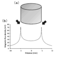
- the magnetic flux density is large at the periphery of the magnet, but the magnetic flux density is small at the center of the magnet. For this reason, if resistance such as friction acts on the magnetic drive microtool at the center of the magnet, the magnetic drive microtool cannot follow the magnetic force, and it is difficult to accurately control the movement of the magnetic drive microtool. There was a problem of being.
- the present invention has been made paying attention to such a problem, and an object thereof is to provide a drive mechanism and a microdevice of a magnetic drive microtool capable of accurately controlling the movement of the magnetic drive microtool.
- a drive mechanism of a magnetic drive microtool is a drive mechanism of a magnetic drive microtool for driving a magnetic drive microtool having magnetism, and periodically changes a magnetic field.
- a magnetic force generator configured to apply a magnetic force to the magnetic drive microtool.
- the magnetic force generator since the magnetic force generator periodically changes the magnetic field, the magnitude and direction of the magnetic force acting on the magnetic drive microtool vary depending on the change of the magnetic field. For this reason, the magnetic drive microtool can be vibrated in conjunction with the periodic change of the magnetic field. Thereby, since the frictional force which acts between a magnetic drive microtool and the support surface etc. which support it can be reduced, a magnetic drive microtool can be made to follow the movement and magnetic force of a magnetic force generation body. For this reason, the movement of the magnetic drive microtool can be accurately controlled by the magnetic force generator.
- the magnetic drive microtool can be driven even with a weak magnetic force compared to the magnetic force when using a permanent magnet. it can. Thereby, the magnetic drive microtool can be driven with smaller energy, and the influence of the magnetic force of the magnetic force generator on the surroundings can be further reduced.
- the magnetic drive microtool when used in a closed space with a ceiling such as a micro-channel, the movement of the magnetic drive microtool in the direction perpendicular to the ceiling is limited.
- the magnetic drive microtool can be driven stably even if the device is vibrated.
- the magnetic drive microtool (MMT) may be any as long as it can be driven by magnetic force.
- the magnetic force generator may be configured in any manner as long as the magnetic field can be periodically changed.
- the magnetic force generator is made of, for example, an electromagnet, and may be configured to periodically change the magnitude and direction of the current flowing through the electromagnet, or to periodically turn on / off the current flowing through the electromagnet.
- the period of change of the magnetic field may be any period as long as the frictional force acting between the magnetic drive microtool and the support surface that supports the magnetic drive microtool can be reduced.
- the magnetic force generator is preferably configured by passing an alternating current through the electromagnet.
- the polarity of the electromagnet is periodically reversed by passing an alternating current through the electromagnet, the direction of the lines of magnetic force is also periodically reversed, and the magnetic field is periodically changed. Therefore, the magnetic drive microtool can be vibrated in conjunction with the periodic change, and the movement of the magnetic drive microtool can be accurately controlled by the magnetic force generator. Further, when the magnetic drive microtool has a ring-shaped portion, an induced current flows through the ring-shaped portion due to a change in the magnetic field of the magnetic force generator, so that the magnetic drive microtool and the magnetic force generator are repelled.
- the magnetic drive microtool floats from the support surface that supports it, and the frictional force acting between the magnetic drive microtool and the support surface can be reduced. Accordingly, the magnetic drive microtool can easily follow the movement and magnetic force of the magnetic force generator, and the movement of the magnetic drive microtool can be accurately controlled by the magnetic force generator.
- the electromagnet protrudes from the end of the coil at at least one end of the core and is formed in a cylindrical shape or a column shape along the length direction of the core. It is preferable to have a protruding portion. In this case, since the magnetic field concentrates on the protrusion, the protrusion can be arranged toward the magnetic drive microtool so that a stronger magnetic force can be applied to the magnetic drive microtool even when the current flowing through the electromagnet is the same. .
- the protruding portion is formed in a cylindrical shape or a column shape along the length direction of the core, locations where the magnetic force is strong are distributed linearly along the edge portion of the distal end surface of the protruding portion. For this reason, the magnetic drive microtool can be captured by a line, and the magnetic drive microtool can be driven in a more stable state.
- the drive mechanism of the magnetic drive microtool according to the present invention may include a thin film made of a material having a high magnetic permeability, disposed between the magnetic force generator and the magnetic drive microtool.
- the thin film can increase the magnetic force acting on the magnetically driven microtool even if the magnetic force generated by the magnetic force generator is the same.
- the microdevice according to the present invention is based on the present invention provided with a microchannel for flowing fine particles, a magnetically driven microtool at least partially disposed in the microchannel, and a drive for the magnetically driven microtool. It has the drive mechanism of the magnetic drive microtool which concerns.
- the microdevice according to the present invention drives the magnetic drive microtool by the drive mechanism of the magnetic drive microtool according to the present invention, the movement of the magnetic drive microtool can be accurately controlled. It is also possible to drive the magnetic drive microtool with less energy. Therefore, operations such as separation, classification, processing, selection, and processing of fine particles such as eggs, cells, and fungi can be performed accurately and with high accuracy in the micro flow channel.
- the microdevice may be an individual micromodule that performs each operation step, or may be a microchip that connects these micromodules.
- the magnetic drive microtool may be provided in a space having a narrow width in the perpendicular direction so that movement in a direction perpendicular to the movement direction is restricted. preferable. In this case, since the movement of the magnetic drive microtool in the direction perpendicular to the moving direction is limited, even if the magnetic driving microtool is vibrated by the driving mechanism, the magnetic driving microtool is stabilized along the moving direction. Can be driven.
- the fine particles are composed of cells having a nucleus inside
- the microchannel has a narrow path portion whose height or width is narrower than the size of the microparticle
- the microparticles are the narrow path.
- It may have a detection device provided to detect the nuclei of the fine particles deformed by optical means when passing through the section.
- the fine particles flowing through the narrow path portion are deformed and moved in a state of being crushed in the width direction or the height direction, it is possible to make the inside of the fine particles easy to observe by reducing the thickness of the fine particles.
- the nucleus can be easily detected by the optical means of the detection device. It is easy to automate the detection of nuclei by the detection device.
- the magnetic drive microtool includes a moving part having magnetism provided so as to be movable along a predetermined plane, and a plurality of fixing parts that elastically fix the moving part.
- the driving mechanism applies a force along the plane to the moving portion
- it is preferable that the moving amount of the moving portion along the plane with respect to the magnitude of the force is isotropic.
- the amount of movement of the moving part by the drive mechanism can be controlled accurately and easily, and the magnetic drive microtool can be easily operated.
- the moving amount of the moving unit is isotropic as long as the moving amount of the moving unit with respect to the force of the same magnitude by the driving mechanism is almost the same in all directions along the plane.
- the movement amount is within 15% error, preferably within 2%.
- the microchannel has a narrow path portion whose height or width is narrower than the size of the fine particles
- the magnetically driven microtool includes a pair, and sandwiches the narrow path portion between each other.
- a needle-like member that is disposed at a position, and is provided on the moving portion so as to protrude toward or away from each other toward the narrow path portion, and the drive mechanism is composed of a pair, and each magnetic drive micro
- the moving part of the corresponding magnetic drive microtool is moved by each drive mechanism to project the needle-like member, thereby deforming
- the fine particles may be divided into two.
- the fine particles flowing through the narrow path portion are deformed and moved in a state of being crushed in the width direction or the height direction, so that the thickness of the fine particles is reduced to facilitate observation of the inside of the fine particles. be able to.
- This also allows the fine particles to be divided into two while observing the inside of the fine particles.
- the fine particles are composed of ova, the ovum can be accurately divided into a portion where nuclei are present and a portion where nuclei are not present, and the enucleation of the ovum can be performed.
- the magnetic drive microtool has a ring-shaped portion, and an induced current flows through the ring-shaped portion due to a change in the magnetic field of the magnetic force generator, and is repelled by the magnetic force generator. It may be.
- the induced current caused by the magnetic force generator flows through the ring-shaped portion, and the magnetic drive microtool and the magnetic force generator are repelled, so that the magnetic drive microtool is lifted from the support surface that supports it.
- the frictional force which acts between a magnetic drive microtool and a support surface can be reduced. Accordingly, the magnetic drive microtool can easily follow the movement and magnetic force of the magnetic force generator, and the movement of the magnetic drive microtool can be accurately controlled by the magnetic force generator.
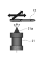
- FIG. 2 A) Side view showing principle of drive mechanism of magnetic drive microtool of embodiment of the present invention, (b) Plan view of magnetic drive microtool, (c) Perspective view showing drive principle by conventional permanent magnet It is. It is a side view which shows the modification which has the protrusion part of the drive mechanism of the magnetic drive microtool of embodiment of this invention.
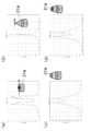
- the shape of the protrusion of the modification of the drive mechanism of the magnetic drive microtool shown in FIG. 2 is (a) a hollow cylindrical shape along the length of the core, (b) a conical shape with a sharp tip, (c It is a graph showing the distribution of magnetic flux density when the tip is formed into a planar truncated cone shape and (d) a cylindrical truncated cone shape having a hollow.
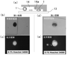
- FIG. 6 is an enlarged plan view of a narrow path portion showing a use state in the enucleation processing of the microdevice shown in FIG. 5.
- 5A is a side view showing the state of fine particles in a micro flow path
- FIG. 5B is a micrograph of bright field observation in a normal deep flow path
- 5C is a fluorescence observation at that time. It is a microscope picture, (d) A microscope picture by bright field observation at the time of a shallow channel of a narrow passage part, (e) A microscope picture by fluorescence observation at that time.
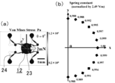
- 5A is a plan view showing a moving state of the moving unit and a von Mises stress when a constant force is applied to the moving unit in a predetermined direction, and FIG. It is a graph which shows the moving amount
- FIG. 1 to 4 show a drive mechanism of a magnetic drive microtool according to an embodiment of the present invention.
- the drive mechanism 11 of the magnetic drive microtool has a magnetic force generator 21 made of an electromagnet.
- the magnetic force generator 21 is configured to cause an alternating current to flow through an electromagnet to periodically reverse the polarity so that the magnetic drive microtool 12 having magnetism acts on the magnetic force. Has been.
- the magnetic drive microtool 12 can be vibrated in conjunction with the periodic change. Thereby, since the frictional force which acts between the magnetic drive microtool 12 and the support surface etc. which support it can be reduced, the magnetic drive microtool 12 can be made to follow the movement and magnetic force of the magnetic force generation body 21. . For this reason, the movement of the magnetic drive microtool 12 can be accurately controlled by the magnetic force generator 21.
- the magnetic drive microtool 12 when the permanent magnet 51 is used, when the magnetic drive microtool 12 is attracted and moved in a direction perpendicular to the attractive force direction, the magnetic drive microtool 12 is moved. Due to the attractive force of the permanent magnet 51 acting on the tool 12, the frictional force acting between the magnetic drive microtool 12 and the support surface that supports it is increased. For this reason, in order to move the magnetic drive microtool 12, a strong magnetic force is required. On the other hand, in the drive mechanism 11, the magnetic drive microtool 12 can be vibrated to reduce the frictional force acting on the magnetic drive microtool 12. The tool 12 can be driven. In one example, it is confirmed that the magnetic drive microtool 12 can be driven with a magnetic force of about 1/20 compared to the permanent magnet 51 when the same size magnet is used.
- the drive mechanism 11 can drive the magnetic drive microtool 12 with smaller energy and can further reduce the influence of the magnetic force of the magnetic force generator 21 on the surroundings. For this reason, a plurality of drive mechanisms 11 can be arranged close to each other in a narrower region without affecting each other, and a micro device using the drive mechanism 11 can be further downsized.
- the magnetic force generator 21 may have a protruding portion 21a protruding from the end of the coil at one end of the core of the electromagnet.
- the protruding portion 21a is arranged toward the magnetic drive microtool 12 so that a stronger magnetic force is applied to the magnetic drive microtool 12 even when the current flowing through the electromagnet is the same. Can act.
- the protrusion 21a has a cylindrical hollow shape (FIG. 3 (a)), a conical shape with a sharp tip (FIG. 3 (b)), and a tip. Is formed into a planar truncated cone shape (FIG. 3C) and a hollow cylindrical truncated cone shape (FIG. 3D), at the edge or tip of the tip surface of the protrusion 21a. It can be confirmed that the magnetic flux density is high. As shown in FIG. 3B, when the tip of the protruding portion 21a is pointed, the magnetic drive microtool 12 is captured by a point because the magnetic flux is concentrated at one point and the magnetic force is increased. In contrast, as shown in FIGS.
- the protruding portion 21a when the protruding portion 21a is formed in a cylindrical shape or a column shape along the length direction of the core, the protruding portion 21a. Since the magnetic flux concentrates linearly along the edge portion of the tip surface and places where the magnetic force is strong are distributed, the magnetic drive microtool 12 can be captured by the line. For this reason, the magnetic drive microtool 12 can be driven in a more stable state than when captured by a point.
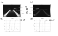
- the drive mechanism 11 may include a thin film 22 made of a material having a high magnetic permeability disposed between the magnetic force generator 21 and the magnetic drive microtool 12.
- the thin film 22 is made of nickel (Ni) and is laid between the glass substrate 13 that supports the magnetic drive microtool 12 and the magnetic drive microtool 12.
- Ni nickel
- the thin film 22 can increase the magnetic force acting on the magnetic drive microtool 12 even if the magnetic force generated by the magnetic force generator 21 is the same.
- a magnetic flux density that is twice or more that of the case without the thin film 22 is obtained.
- the microdevice 10 includes a drive mechanism 11, a magnetic drive microtool 12, and a microchannel 14 through which the fine particles 1 flow.
- the microchannel 14 is formed inside a transparent glass substrate 13, and can be any animal cell such as an egg (egg cell) or somatic cell, a plant cell, an ES cell, a microorganism, a fungus, a DNA molecule, a nanotube, or a nanomaterial.
- a fine particle 1 made of a minute object such as is made to flow.
- the microchannel 14 has, in part, a narrow channel portion 14 a formed so that the height direction is narrower than the size of the fine particles 1.
- the magnetic drive microtool 12 has a substantially circular moving part 23 and four fixed parts 24.
- the moving part 23 includes a circular base 23a made of a flexible polymer material and a needle-like member 23b made of a rigid nickel material fixed to the base 23a.
- Each fixing portion 24 is made of a flexible polymer material and is formed in an elongated string shape. One end of each fixing portion 24 is connected to the peripheral portion of the base 23a of the moving portion 23 at an interval of 90 degrees with respect to the center of the base 23a.
- Each fixing portion 24 extends in parallel from the peripheral edge of the base 23a with respect to a straight line (hereinafter referred to as a “reference straight line”) that is parallel to the surface of the base 23a and passes through the center of the base 23a.
- a straight line hereinafter referred to as a “reference straight line”
- Each fixing portion 24 has a circular reinforcing portion at the connection position with the moving portion 23 corresponding to the joint, the bent position, and the other end.
- the needle-like member 23b has a pointed end 23c formed in a needle shape, and an opposite end 23d formed in a circular shape on the opposite side to the pointed end 23c.
- the needle-like member 23b is parallel to the surface of the base 23a and perpendicular to the reference straight line, and the base 23a at the opposite end 23d so that the tip 23c protrudes outward from the peripheral edge of the base 23a. It is fixed in the upper center of the.
- the needle-like member 23b is made of a nickel material and has magnetism.
- the magnetic drive microtool 12 is composed of a pair, and is fixed to both sides of the narrow path portion 14a so as to sandwich the narrow path portion 14a of the micro flow path 14, respectively.
- Each magnetic drive microtool 12 includes a transparent glass substrate 13 that forms a microchannel 14 at the other end of each fixing portion 24 so that the surface of the base 23a is parallel to the width direction of the narrow path portion 14a. It is fixed to.
- each magnetic drive microtool 12 is arranged such that the tip 23c of the needle-like member 23b is opposed to the narrow path portion 14a.
- Each magnetic drive microtool 12 has a moving part 23 elastically fixed by each fixing part 24 made of a flexible polymer material, and can move along a plane parallel to the surface of the base 23a. Yes.
- Each magnetic drive microtool 12 is provided in a narrow space sandwiched between the glass substrates 13 in a direction perpendicular to the moving direction, and movement in the vertical direction is restricted.
- the moving part 23 of each magnetic drive microtool 12 is located at the center of each fixing part 24 when no force is applied, and after moving in any direction after the force is applied, each moving part 23 is fixed when the force is removed. Due to the elasticity of the portion 24, it returns to the center of each fixed portion 24.
- the drive mechanism 11 consists of a pair and is provided below the glass substrate 13 corresponding to each magnetic drive microtool 12 so that the corresponding magnetic drive microtool 12 can be driven.
- the drive mechanism 11 can move the moving part 23 of each magnetic drive microtool 12 such that the tip 23c of the needle-like member 23b protrudes toward the narrow path part 14a.
- the microdevice 10 is configured to divide the microparticles 1 into two at the needle-like tips 23c of the needle-like member 23b when the microparticles 1 flow into the narrow path portion 14a. ing.
- the microdevice 10 drives the magnetic drive microtool 12 by the drive mechanism 11, the movement of the magnetic drive microtool 12 can be accurately controlled. Further, the magnetic drive microtool 12 can be driven with smaller energy. Since the magnetic drive microtool 12 is restricted from moving in the direction perpendicular to the moving direction, even if the magnetic drive microtool 12 is vibrated by the drive mechanism 11, the magnetic drive microtool 12 is moved along the moving direction. It can be driven stably.
- the thickness of the fine particles 1 is reduced and the inside of the fine particles 1 is observed. Can be easier. This also allows the fine particles 1 to be divided into two while observing the inside of the fine particles 1.
- the nucleus can be clearly observed in the deformed and crushed egg, so that it is accurate to the part where the nucleus exists and the part where the nucleus does not exist. The egg can be enucleated.
- the position of the fine particle 1 and the position of the nucleus in the fine particle 1 are automatically detected by performing image processing on the fine particle 1 in the narrow path portion 14a by a detection device having an optical means, and the drive mechanism 11 is based on the detected position.
- the magnetic drive microtool 12 can be driven to divide the microparticles 1 and automation of the enucleation process can be achieved. Processing automation can improve processing speed, processing efficiency and processing accuracy, and achieve uniform processing regardless of operator skill.
- FIG. 8 along the plane when the driving mechanism 11 applies a constant force in a predetermined direction along the plane parallel to the surface of the base 23a to the moving unit 23 of the magnetic drive microtool 12.
- the result of examining the movement amount of the moving unit 23 is shown.
- the moving amount of the moving unit 23 with respect to the same force is within an error of 2% in all directions, and it was confirmed that the moving portion 23 is almost isotropic. Therefore, it can be said that the micro device 10 can accurately and easily control the movement amount of the moving unit 23 by the driving mechanism 11 and can easily operate the magnetic driving micro tool 12.
- the moving unit 23 can be moved not only in one direction but also in any direction in the plane, and the degree of freedom of operation of the magnetic drive microtool 12 can be increased.
- the magnetic drive microtool 12 may have a ring-shaped portion, and an induced current may flow through the ring-shaped portion due to a change in the magnetic field of the magnetic force generator 21 to repel the magnetic force generator 21.
- the magnetic drive microtool 12 since the induced current caused by the magnetic force generator 21 flows through the ring-shaped portion and the magnetic drive microtool 12 and the magnetic force generator 21 repel, the magnetic drive microtool 12 is lifted from the glass substrate 13 that supports it. For this reason, the frictional force which acts between the magnetic drive microtool 12 and the glass substrate 13 can be reduced. Thereby, the magnetic drive microtool 12 can easily follow the movement and magnetic force of the magnetic force generator 21, and the movement of the magnetic drive microtool 12 can be accurately controlled by the magnetic force generator 21.
- the drive mechanism 11 can be used in various operations using the magnetic drive microtool 12 such as separation, classification, processing, selection, and processing of the fine particles 1 without being limited to the enucleation of the egg.
- the microdevice 10 is not limited to the one that performs the enucleation treatment of the ovum, but may be one that performs various operations such as separation, classification, processing, selection, and processing of the fine particles 1.
Landscapes
- Chemical & Material Sciences (AREA)
- Dispersion Chemistry (AREA)
- Physics & Mathematics (AREA)
- Health & Medical Sciences (AREA)
- Life Sciences & Earth Sciences (AREA)
- Analytical Chemistry (AREA)
- Biochemistry (AREA)
- General Health & Medical Sciences (AREA)
- General Physics & Mathematics (AREA)
- Immunology (AREA)
- Pathology (AREA)
- Micromachines (AREA)
- Apparatus Associated With Microorganisms And Enzymes (AREA)
- Micro-Organisms Or Cultivation Processes Thereof (AREA)
- Physical Or Chemical Processes And Apparatus (AREA)
Abstract
【課題】磁気駆動マイクロツールの動きを正確に制御することができる磁気駆動マイクロツールの駆動機構およびマイクロデバイスを提供する。 【解決手段】電磁石から成る磁力発生体21を有している。磁力発生体21は、電磁石に交流電流を流して周期的に極性を反転し、磁性を有する磁気駆動マイクロツール12に磁力を作用させるよう構成されている。電磁石は、芯の少なくとも一方の端部に、コイルの端部から突出して、芯の長さ方向に沿って筒状または柱状に形成された突出部21aを有していてもよい。また、磁力発生体21と磁気駆動マイクロツール12との間に配置された、透磁率の大きい材質から成る薄膜22を有していてもよい。
Description
本発明は、磁気駆動マイクロツールの駆動機構およびマイクロデバイスに関する。
主に医療分野、医薬分野、品種改良といったバイオ系産業分野において、卵子、細胞、菌などの微粒子に対して、分離、分類、加工、選択、処理等の一連の操作が行われている。従来、このような微粒子に対する操作を行う装置として、永久磁石や電磁石により駆動される磁気駆動マイクロツール(MMT)を使用して、微小流路を流れる微粒子に対して各操作を行うものがある(例えば、特許文献1または2参照)。
特許文献1または2に記載のような装置では、円柱状の永久磁石や電磁石を、一方の端面を磁気駆動マイクロツールに向けて配置し、永久磁石を動かしたり、電磁石に流す電流をON/OFFしたりして、磁気駆動マイクロツールを駆動している。このとき、図9に示すように、円柱状の磁石では、磁石の周縁部で磁束密度が大きいが、磁石の中心部では磁束密度が小さくなっている。このため、磁石の中心部では、磁気駆動マイクロツールに摩擦等の抵抗が働くと、磁気駆動マイクロツールを磁力に追従させることができず、磁気駆動マイクロツールの動きを正確に制御するのが困難であるという課題があった。
これに対し、磁石の中心部での磁束密度を大きくするために、磁石を小さくすることが考えられるが、小型化にも限界があり、また、小さくするに従って磁力も弱くなるため、やはり磁気駆動マイクロツールの動きを正確に制御することは困難になる。
また、磁石で磁気駆動マイクロツールを引きつけ、その引力方向に対して垂直方向に磁気駆動マイクロツールを移動させるとき、磁気駆動マイクロツールに作用する磁石の引力により、磁気駆動マイクロツールとそれを支える支持面等との間に働く摩擦力が大きくなる。このため、この場合にも、磁気駆動マイクロツールの動きを正確に制御するのが困難であるという課題があった。
本発明は、このような課題に着目してなされたもので、磁気駆動マイクロツールの動きを正確に制御することができる磁気駆動マイクロツールの駆動機構およびマイクロデバイスを提供することを目的としている。
上記目的を達成するために、本発明に係る磁気駆動マイクロツールの駆動機構は、磁性を有する磁気駆動マイクロツールを駆動するための磁気駆動マイクロツールの駆動機構であって、周期的に磁場を変化させて、前記磁気駆動マイクロツールに磁力を作用させるよう構成された磁力発生体を有することを、特徴とする。
本発明に係る磁気駆動マイクロツールの駆動機構では、磁力発生体が周期的に磁場を変化させるため、磁気駆動マイクロツールに作用する磁力の大きさや向きが、磁場の変化により変動する。このため、磁場の周期的に変化に連動して、磁気駆動マイクロツールを振動させることができる。これにより、磁気駆動マイクロツールとそれを支える支持面等との間に働く摩擦力を低減することができるため、磁力発生体の動きや磁力に磁気駆動マイクロツールを追従させることができる。このため、磁力発生体により磁気駆動マイクロツールの動きを正確に制御することができる。
また、磁気駆動マイクロツールが振動して磁気駆動マイクロツールに働く摩擦力を低減することができるため、永久磁石を使用したときの磁力と比べて弱い磁力でも、磁気駆動マイクロツールを駆動することができる。これにより、より小さいエネルギーで磁気駆動マイクロツールを駆動することができるとともに、磁力発生体の磁力が周囲に及ぼす影響をより小さくすることができる。また、磁気駆動マイクロツールを微小流路のように天井のある閉空間内で使用する場合には、磁気駆動マイクロツールの天井に対して垂直な方向の動きが制限されるため、磁気駆動マイクロツールを振動させても、磁気駆動マイクロツールを安定して駆動することができる。なお、磁気駆動マイクロツール(MMT)は、磁力により駆動可能であれば、いかなるものであってもよい。
磁力発生体は、周期的に磁場を変化可能であれば、どのように構成されていてもよい。磁力発生体は、例えば、電磁石から成り、電磁石に流す電流の大きさや向きを周期的に変化させたり、電磁石に流す電流を周期的にON/OFFしたりするよう構成されていてもよい。磁場の変化の周期は、磁気駆動マイクロツールとそれを支える支持面等との間に働く摩擦力を低減可能であれば、いかなる周期であってもよい。
本発明に係る磁気駆動マイクロツールの駆動機構で、前記磁力発生体は電磁石に交流電流を流して構成されることが好ましい。この場合、電磁石に交流電流を流すことにより、電磁石の極性が周期的に反転するため、磁力線の向きも周期的に反転し、磁場が周期的に変化する。このため、その周期的な変化に連動して磁気駆動マイクロツールを振動させることができ、磁力発生体により磁気駆動マイクロツールの動きを正確に制御することができる。また、磁気駆動マイクロツールがリング状部を有しする場合には、磁力発生体の磁場の変化によりリング状部に誘導電流が流れるため、磁気駆動マイクロツールと磁力発生体とが反発する。このため、磁気駆動マイクロツールがそれを支える支持面から浮き上がり、磁気駆動マイクロツールと支持面との間に働く摩擦力を低減することができる。これにより、磁力発生体の動きや磁力に磁気駆動マイクロツールを容易に追従させることができ、磁力発生体により磁気駆動マイクロツールの動きを正確に制御することができる。
本発明に係る磁気駆動マイクロツールの駆動機構で、前記電磁石は、芯の少なくとも一方の端部に、コイルの端部から突出して、前記芯の長さ方向に沿って筒状または柱状に形成された突出部を有することが好ましい。この場合、突出部に磁場が集中するため、突出部を磁気駆動マイクロツール側に向けて配置することにより、電磁石に流れる電流が同じでも、より強い磁力を磁気駆動マイクロツールに作用させることができる。また、突出部が芯の長さ方向に沿って筒状または柱状に形成されているため、突出部の先端面の縁部に沿って線状に磁力の強い場所が分布する。このため、磁気駆動マイクロツールを線で捕らえることができ、より安定した状態で磁気駆動マイクロツールを駆動することができる。
本発明に係る磁気駆動マイクロツールの駆動機構は、前記磁力発生体と前記磁気駆動マイクロツールとの間に配置された、透磁率の大きい材質から成る薄膜を有してもよい。この場合、薄膜により、磁力発生体で発する磁力が同じであっても、磁気駆動マイクロツールに作用する磁力を高めることができる。
本発明に係るマイクロデバイスは、微粒子を流す微小流路と、少なくとも一部が前記微小流路内に配置された磁気駆動マイクロツールと、前記磁気駆動マイクロツールを駆動可能に設けられた本発明に係る磁気駆動マイクロツールの駆動機構とを有することを、特徴とする。
本発明に係るマイクロデバイスは、本発明に係る磁気駆動マイクロツールの駆動機構により磁気駆動マイクロツールを駆動するため、磁気駆動マイクロツールの動きを正確に制御することができる。また、より小さいエネルギーで磁気駆動マイクロツールを駆動することもできる。このため、微小流路内で、卵子、細胞、菌などの微粒子の分離、分類、加工、選択、処理等の操作を、正確かつ高精度で行うことができる。なお、マイクロデバイスは、各操作の工程を行う個々のマイクロモジュールであってもよく、これらのマイクロモジュールを連結したマイクロチップであってもよい。
本発明に係るマイクロデバイスで、前記磁気駆動マイクロツールは、移動方向に対して垂直な方向への動きが制限されるよう、前記垂直な方向での幅が狭い空間内に設けられていることが好ましい。この場合、磁気駆動マイクロツールが移動方向に対して垂直な方向への動きが制限されるため、駆動機構により磁気駆動マイクロツールを振動させても、磁気駆動マイクロツールを移動方向に沿って安定して駆動することができる。
本発明に係るマイクロデバイスで、前記微粒子は内部に核を有する細胞から成り、前記微小流路は前記微粒子の大きさよりも高さまたは幅が狭い狭路部を有し、前記微粒子が前記狭路部を通過するとき、光学的手段により変形した前記微粒子の核を検出するよう設けられた検出装置を有していてもよい。この場合、狭路部を流れる微粒子が幅方向または高さ方向に潰れた状態で変形して移動するため、微粒子の厚みを薄くして微粒子の内部を観察しやすくすることができる。このため、検出装置の光学的手段により容易に核を検出することができる。検出装置による核の検出の自動化が容易である。
本発明に係るマイクロデバイスで、前記磁気駆動マイクロツールは、所定の平面に沿って移動可能に設けられた磁性を有する移動部と、前記移動部を弾性的に固定する複数の固定部とを有し、前記駆動機構により前記移動部に前記平面に沿った力を作用させたとき、前記力の大きさに対する前記平面に沿った前記移動部の移動量が等方的であることが好ましい。この場合、駆動機構による移動部の移動量の制御を正確かつ容易に行うことができ、磁気駆動マイクロツールを操作しやすい。なお、ここで移動部の移動量が等方的であるとは、平面に沿った全ての向きで、駆動機構による同じ大きさの力に対する移動部の移動量が概ね同じ大きさであればよく、移動量が誤差15%以内、好ましくは2%以内に収まることをいう。
本発明に係るマイクロデバイスで、前記微小流路は前記微粒子の大きさよりも高さまたは幅が狭い狭路部を有し、前記磁気駆動マイクロツールは1対から成り、互いに前記狭路部を挟んだ位置に配置され、前記移動部に前記狭路部に向かって互いに対向してまたはすれ違って突出するよう設けられた針状部材を有し、前記駆動機構は1対から成り、各磁気駆動マイクロツールに対応して設けられ、前記狭路部に前記微粒子が流れてきたとき、各駆動機構により対応する磁気駆動マイクロツールの前記移動部を移動させて前記針状部材を突出させることにより、変形した前記微粒子を2つに分割するよう構成されていてもよい。
この微粒子を2つに分割する場合、狭路部を流れる微粒子が幅方向または高さ方向に潰れた状態で変形して移動するため、微粒子の厚みを薄くして微粒子の内部を観察しやすくすることができる。また、これにより、微粒子の内部を観察しながら、微粒子を2つに分割することができる。微粒子が卵子から成る場合、卵子を、核が存在する部分と核が存在しない部分とに正確に分割することができ、卵子の除核処理を行うことができる。
本発明に係るマイクロデバイスで、前記磁気駆動マイクロツールはリング状部を有し、前記磁力発生体の磁場の変化により前記リング状部に誘導電流が流れ、前記磁力発生体と反発するよう構成されていてもよい。この場合、磁力発生体による誘導電流がリング状部に流れ、磁気駆動マイクロツールと磁力発生体とが反発するため、磁気駆動マイクロツールがそれを支える支持面から浮き上がる。このため、磁気駆動マイクロツールと支持面との間に働く摩擦力を低減することができる。これにより、磁力発生体の動きや磁力に磁気駆動マイクロツールを容易に追従させることができ、磁力発生体により磁気駆動マイクロツールの動きを正確に制御することができる。
本発明によれば、磁気駆動マイクロツールの動きを正確に制御することができる磁気駆動マイクロツールの駆動機構およびマイクロデバイスを提供することができる。
以下、図面に基づき本発明の実施の形態について説明する。
図1乃至図4は、本発明の実施の形態の磁気駆動マイクロツールの駆動機構を示している。
図1乃至図4は、本発明の実施の形態の磁気駆動マイクロツールの駆動機構を示している。
図1(a)に示すように、磁気駆動マイクロツールの駆動機構11は、電磁石から成る磁力発生体21を有している。図1(a)および(b)に示すように、磁力発生体21は、電磁石に交流電流を流して周期的に極性を反転し、磁性を有する磁気駆動マイクロツール12に磁力を作用させるよう構成されている。
駆動機構11では、電磁石に交流電流を流すことにより、電磁石の極性が周期的に反転するため、磁力線の向きも周期的に反転し、磁場が周期的に変化する。このため、その周期的な変化に連動して磁気駆動マイクロツール12を振動させることができる。これにより、磁気駆動マイクロツール12とそれを支える支持面等との間に働く摩擦力を低減することができるため、磁力発生体21の動きや磁力に磁気駆動マイクロツール12を追従させることができる。このため、磁力発生体21により磁気駆動マイクロツール12の動きを正確に制御することができる。
また、図1(c)に示すように、永久磁石51を使用する場合、磁気駆動マイクロツール12を引きつけ、その引力方向に対して垂直方向に磁気駆動マイクロツール12を移動させるとき、磁気駆動マイクロツール12に作用する永久磁石51の引力により、磁気駆動マイクロツール12とそれを支える支持面等との間に働く摩擦力が大きくなる。このため、磁気駆動マイクロツール12を動かすために、強い磁力が必要となる。これに対し、駆動機構11では、磁気駆動マイクロツール12を振動させて、磁気駆動マイクロツール12に働く摩擦力を低減することができるため、永久磁石51の場合と比べて弱い磁力でも磁気駆動マイクロツール12を駆動することができる。一例では、同じ大きさの磁石を使用した場合、永久磁石51と比べて約1/20の磁力で磁気駆動マイクロツール12を駆動できることが確認されている。
このように、駆動機構11は、より小さいエネルギーで磁気駆動マイクロツール12を駆動することができるとともに、磁力発生体21の磁力が周囲に及ぼす影響をより小さくすることができる。このため、より狭い領域に、互いに影響を及ぼすことなく複数の駆動機構11を近接して配置することができ、駆動機構11を利用したマイクロデバイスをより小型化することができる。
なお、図2に示すように、磁力発生体21は、電磁石の芯の一方の端部に、コイルの端部から突出した突出部21aを有していてもよい。この場合、突出部21aに磁場が集中するため、突出部21aを磁気駆動マイクロツール12の側に向けて配置することにより、電磁石に流れる電流が同じでも、より強い磁力を磁気駆動マイクロツール12に作用させることができる。
図3に示すように、突出部21aの形状を、芯の長さ方向に沿った円筒状の中空形状(図3(a))、先端が尖った円錐形状(図3(b))、先端が平面状の円錐台形状(図3(c))、中空を有する円筒状の円錐台形状(図3(d))に形成したとき、突出部21aの先端面の縁部や尖端の位置で、磁束密度が高くなっているのが確認できる。図3(b)に示すように、突出部21aの先端が尖っている場合、磁束が一点に集中して磁力が強くなっているため、磁気駆動マイクロツール12を点で捕らえることになる。これに対し、図3(a)、(c)、(d)に示すように、突出部21aが芯の長さ方向に沿って筒状または柱状に形成されている場合には、突出部21aの先端面の縁部に沿って線状に磁束が集中して磁力の強い場所が分布するため、磁気駆動マイクロツール12を線で捕らえることができる。このため、点で捕らえる場合よりも、安定した状態で磁気駆動マイクロツール12を駆動することができる。
また、図4に示すように、駆動機構11は、磁力発生体21と磁気駆動マイクロツール12との間に配置された、透磁率の大きい材質から成る薄膜22を有してもよい。薄膜22は、ニッケル(Ni)製で、磁気駆動マイクロツール12を支持するガラス基板13と、磁気駆動マイクロツール12との間に敷かれている。この場合、薄膜22により、磁力発生体21で発する磁力が同じであっても、磁気駆動マイクロツール12に作用する磁力を高めることができる。図4に示す一例では、薄膜22がない場合に比べて、2倍以上の磁束密度が得られている。
図5乃至図8は、本発明の実施の形態のマイクロデバイスを示している。
図5に示すように、マイクロデバイス10は、駆動機構11と磁気駆動マイクロツール12と、微粒子1を流す微小流路14とを有している。
図5に示すように、マイクロデバイス10は、駆動機構11と磁気駆動マイクロツール12と、微粒子1を流す微小流路14とを有している。
微小流路14は、透明なガラス基板13の内部に形成されており、卵子(卵細胞)、体細胞等の任意の動物細胞、植物細胞、ES細胞、微生物、菌、DNA分子、ナノチューブ、ナノ材料等の微小物体などから成る微粒子1を流すようになっている。微小流路14は、一部に、微粒子1の大きさよりも高さ方向が狭く形成された狭路部14aを有している。
磁気駆動マイクロツール12は、ほぼ円形の移動部23と4つの固定部24とを有している。移動部23は、柔軟性のポリマー素材から成る円形の基台23aと、基台23aに固定された剛性のニッケル素材から成る針状部材23bとを有している。各固定部24は、柔軟性のポリマー素材から成り、細長い紐状に形成されている。各固定部24は、移動部23の基台23aの周縁部に、基台23aの中心に対して90度間隔で、それぞれ一端が接続されている。各固定部24は、基台23aの表面に対して平行で基台23aの中心を通る直線(以下、「参考直線」という)に対して、基台23aの周縁部からそれぞれ平行に伸び、中間部で参考直線から離れる方向に、参考直線に対してほぼ垂直に伸びるよう折れ曲がっている。各固定部24は、関節に対応する移動部23との接続位置、折れ曲がり位置および他端に、円形の補強部を有している。針状部材23bは、針状に形成された尖端23cと、尖端23cとは反対側に円形状に形成された反対端23dとを有している。針状部材23bは、基台23aの表面に対して平行かつ参考直線に対して垂直を成し、尖端23cが基台23aの周縁より外側に向かって突出するよう、反対端23dで基台23aの上部中央に固定されている。
磁気駆動マイクロツール12は、針状部材23bがニッケル素材から成り、磁性を有している。磁気駆動マイクロツール12は、1対から成り、それぞれ微小流路14の狭路部14aを挟むよう、狭路部14aの両脇に固定されている。各磁気駆動マイクロツール12は、基台23aの表面が狭路部14aの幅方向に対して平行になるよう、各固定部24の他端で、微小流路14を形成する透明なガラス基板13に固定されている。また、各磁気駆動マイクロツール12は、それぞれ針状部材23bの尖端23cが、狭路部14aを挟んで対向するように配置されている。
各磁気駆動マイクロツール12は、移動部23が、柔軟性のポリマー素材から成る各固定部24により弾性的に固定されており、基台23aの表面に平行な平面に沿って移動可能になっている。また、各磁気駆動マイクロツール12は、移動方向に対して垂直な方向でガラス基板13により挟まれた幅の狭い空間内に設けられており、垂直な方向への動きが制限されている。各磁気駆動マイクロツール12の移動部23は、力が作用しないとき、各固定部24の中央に位置し、力が作用して任意の方向に移動した後、力が除かれたとき、各固定部24の弾性により各固定部24の中央に戻るようになっている。
駆動機構11は、1対から成り、各磁気駆動マイクロツール12に対応してガラス基板13の下部に設けられ、対応する磁気駆動マイクロツール12を駆動可能になっている。駆動機構11は、針状部材23bの尖端23cが狭路部14aに向かって互いにすれ違って突出するよう、各磁気駆動マイクロツール12の移動部23を移動可能になっている。これにより、図6に示すように、マイクロデバイス10は、狭路部14aに微粒子1が流れてきたとき、針状部材23bの針状の尖端23cで微粒子1を2つに分割するよう構成されている。
次に、作用について説明する。
マイクロデバイス10は、駆動機構11により磁気駆動マイクロツール12を駆動するため、磁気駆動マイクロツール12の動きを正確に制御することができる。また、より小さいエネルギーで磁気駆動マイクロツール12を駆動することもできる。磁気駆動マイクロツール12が移動方向に対して垂直な方向への動きが制限されているため、駆動機構11により磁気駆動マイクロツール12を振動させても、磁気駆動マイクロツール12を移動方向に沿って安定して駆動することができる。
マイクロデバイス10は、駆動機構11により磁気駆動マイクロツール12を駆動するため、磁気駆動マイクロツール12の動きを正確に制御することができる。また、より小さいエネルギーで磁気駆動マイクロツール12を駆動することもできる。磁気駆動マイクロツール12が移動方向に対して垂直な方向への動きが制限されているため、駆動機構11により磁気駆動マイクロツール12を振動させても、磁気駆動マイクロツール12を移動方向に沿って安定して駆動することができる。
図7に示すように、マイクロデバイス10では、狭路部14aを流れる微粒子1が高さ方向に潰れた状態で変形して移動するため、微粒子1の厚みを薄くして微粒子1の内部を観察しやすくすることができる。また、これにより、微粒子1の内部を観察しながら、微粒子1を2つに分割することができる。図7に示す一例では、微粒子1の卵子が狭路部14aを流れるとき、変形して潰れた卵子内に核が明瞭に観察できるため、核が存在する部分と核が存在しない部分とに正確に分割することができ、卵子の除核処理を行うことができる。また、光学的手段を有する検出装置などにより、狭路部14aの微粒子1を画像処理することにより、微粒子1の位置や微粒子1内の核の位置を自動で検出し、それに基づいて駆動機構11で磁気駆動マイクロツール12を駆動して微粒子1を分割することができ、除核処理の自動化を図ることができる。処理の自動化により、処理速度、処理効率および処理精度の向上、作業者の技能に左右されない処理の均一化を図ることができる。
図8に、駆動機構11により、磁気駆動マイクロツール12の移動部23に、基台23aの表面に平行な平面に沿って所定の方向に一定の力を作用させたときの、その平面に沿った移動部23の移動量を調べた結果を示す。図8に示すように、同じ大きさの力に対する移動部23の移動量は、全ての方向で誤差2%以内に収まっており、ほぼ等方的であることが確認された。このため、マイクロデバイス10は、駆動機構11による移動部23の移動量の制御を正確かつ容易に行うことができ、磁気駆動マイクロツール12を操作しやすいといえる。また、移動部23を一方向だけでなく、平面内の任意の方向に移動させることができ、磁気駆動マイクロツール12の操作の自由度を高めることができる。
なお、磁気駆動マイクロツール12はリング状部を有し、磁力発生体21の磁場の変化によりリング状部に誘導電流が流れ、磁力発生体21と反発するよう構成されていてもよい。この場合、磁力発生体21による誘導電流がリング状部に流れ、磁気駆動マイクロツール12と磁力発生体21とが反発するため、磁気駆動マイクロツール12がそれを支えるガラス基板13から浮き上がる。このため、磁気駆動マイクロツール12とガラス基板13との間に働く摩擦力を低減することができる。これにより、磁力発生体21の動きや磁力に磁気駆動マイクロツール12を容易に追従させることができ、磁力発生体21により磁気駆動マイクロツール12の動きを正確に制御することができる。
駆動機構11は、卵子の除核処理に限らず、微粒子1の分離、分類、加工、選択、処理等の磁気駆動マイクロツール12を使用する様々な操作で使用可能である。また、マイクロデバイス10は、卵子の除核処理を行うものに限らず、微粒子1の分離、分類、加工、選択、処理等の様々な操作を行うものから成っていてもよい。
1 微粒子
10 マイクロデバイス
11 駆動機構
12 磁気駆動マイクロツール
13 ガラス基板
14 微小流路
14a 狭路部
21 磁力発生体
21a 突出部
22 薄膜
23 移動部
23a 基台
23b 針状部材
23c 尖端
23d 反対端
24 固定部
10 マイクロデバイス
11 駆動機構
12 磁気駆動マイクロツール
13 ガラス基板
14 微小流路
14a 狭路部
21 磁力発生体
21a 突出部
22 薄膜
23 移動部
23a 基台
23b 針状部材
23c 尖端
23d 反対端
24 固定部
Claims (10)
- 磁性を有する磁気駆動マイクロツールを駆動するための磁気駆動マイクロツールの駆動機構であって、
周期的に磁場を変化させて、前記磁気駆動マイクロツールに磁力を作用させるよう構成された磁力発生体を有することを、
特徴とする磁気駆動マイクロツールの駆動機構。 - 前記磁力発生体は電磁石に交流電流を流して構成されることを、特徴とする請求項1記載の磁気駆動マイクロツールの駆動機構。
- 前記電磁石は、芯の少なくとも一方の端部に、コイルの端部から突出して、前記芯の長さ方向に沿って筒状または柱状に形成された突出部を有することを、特徴とする請求項2記載の磁気駆動マイクロツールの駆動機構。
- 前記磁力発生体と前記磁気駆動マイクロツールとの間に配置された、透磁率の大きい材質から成る薄膜を有することを、特徴とする請求項1、2または3記載の磁気駆動マイクロツールの駆動機構。
- 微粒子を流す微小流路と、
少なくとも一部が前記微小流路内に配置された磁気駆動マイクロツールと、
前記磁気駆動マイクロツールを駆動可能に設けられた請求項1、2、3または4記載の磁気駆動マイクロツールの駆動機構とを有することを、
特徴とするマイクロデバイス。 - 前記磁気駆動マイクロツールは、移動方向に対して垂直な方向への動きが制限されるよう、前記垂直な方向での幅が狭い空間内に設けられていることを、特徴とする請求項5記載のマイクロデバイス。
- 前記微粒子は内部に核を有する細胞から成り、
前記微小流路は前記微粒子の大きさよりも高さまたは幅が狭い狭路部を有し、
前記微粒子が前記狭路部を通過するとき、光学的手段により変形した前記微粒子の核を検出するよう設けられた検出装置を有することを、
特徴とする請求項5または6記載のマイクロデバイス。 - 前記磁気駆動マイクロツールは、所定の平面に沿って移動可能に設けられた磁性を有する移動部と、前記移動部を弾性的に固定する複数の固定部とを有し、前記駆動機構により前記移動部に前記平面に沿った力を作用させたとき、前記力の大きさに対する前記平面に沿った前記移動部の移動量が等方的であることを、特徴とする請求項5、6または7記載のマイクロデバイス。
- 前記微小流路は前記微粒子の大きさよりも高さまたは幅が狭い狭路部を有し、
前記磁気駆動マイクロツールは1対から成り、互いに前記狭路部を挟んだ位置に配置され、前記移動部に前記狭路部に向かって互いに対向してまたはすれ違って突出するよう設けられた針状部材を有し、
前記駆動機構は1対から成り、各磁気駆動マイクロツールに対応して設けられ、
前記狭路部に前記微粒子が流れてきたとき、各駆動機構により対応する磁気駆動マイクロツールの前記移動部を移動させて前記針状部材を突出させることにより、変形した前記微粒子を2つに分割するよう構成されていることを、
特徴とする請求項8記載のマイクロデバイス。 - 前記磁気駆動マイクロツールはリング状部を有し、前記磁力発生体の磁場の変化により前記リング状部に誘導電流が流れ、前記磁力発生体と反発するよう構成されていることを、特徴とする請求項5、6、7、8または9記載のマイクロデバイス。
Applications Claiming Priority (2)
| Application Number | Priority Date | Filing Date | Title |
|---|---|---|---|
| JP2009210903A JP2011055791A (ja) | 2009-09-11 | 2009-09-11 | 磁気駆動マイクロツールの駆動機構およびマイクロデバイス |
| JP2009-210903 | 2009-09-11 |
Publications (1)
| Publication Number | Publication Date |
|---|---|
| WO2011030623A1 true WO2011030623A1 (ja) | 2011-03-17 |
Family
ID=43732297
Family Applications (1)
| Application Number | Title | Priority Date | Filing Date |
|---|---|---|---|
| PCT/JP2010/062265 Ceased WO2011030623A1 (ja) | 2009-09-11 | 2010-07-21 | 磁気駆動マイクロツールの駆動機構およびマイクロデバイス |
Country Status (2)
| Country | Link |
|---|---|
| JP (1) | JP2011055791A (ja) |
| WO (1) | WO2011030623A1 (ja) |
Families Citing this family (2)
| Publication number | Priority date | Publication date | Assignee | Title |
|---|---|---|---|---|
| JP5578615B2 (ja) * | 2010-05-11 | 2014-08-27 | 国立大学法人名古屋大学 | マイクロ流体チップ内における磁気駆動マイクロツールの駆動機構 |
| TWI415369B (zh) * | 2011-06-24 | 2013-11-11 | Univ Nat Cheng Kung | 充磁裝置 |
Citations (2)
| Publication number | Priority date | Publication date | Assignee | Title |
|---|---|---|---|---|
| JP2006325429A (ja) * | 2005-05-23 | 2006-12-07 | National Institute Of Advanced Industrial & Technology | 自動核移植装置 |
| JP2008148677A (ja) * | 2006-12-16 | 2008-07-03 | Fumito Arai | マイクロ磁気ツールの製造方法及びマイクロ磁気ツールデバイスの製造方法 |
-
2009
- 2009-09-11 JP JP2009210903A patent/JP2011055791A/ja active Pending
-
2010
- 2010-07-21 WO PCT/JP2010/062265 patent/WO2011030623A1/ja not_active Ceased
Patent Citations (2)
| Publication number | Priority date | Publication date | Assignee | Title |
|---|---|---|---|---|
| JP2006325429A (ja) * | 2005-05-23 | 2006-12-07 | National Institute Of Advanced Industrial & Technology | 自動核移植装置 |
| JP2008148677A (ja) * | 2006-12-16 | 2008-07-03 | Fumito Arai | マイクロ磁気ツールの製造方法及びマイクロ磁気ツールデバイスの製造方法 |
Non-Patent Citations (1)
| Title |
|---|
| YOKO YAMANISHI ET AL.: "Sorting of Micro- particles using Magnetically Driven Micro- tools", JOURNAL OF THE ROBOTICS SOCIETY OF JAPAN, vol. 27, no. 3, 15 April 2009 (2009-04-15), pages 307 - 313 * |
Also Published As
| Publication number | Publication date |
|---|---|
| JP2011055791A (ja) | 2011-03-24 |
Similar Documents
| Publication | Publication Date | Title |
|---|---|---|
| CN112041069B (zh) | 用于在一反应腔室中致动数个磁反应性微柱的磁基致动机构及方法 | |
| Xu | Micromachines for biological micromanipulation | |
| US9931632B2 (en) | Dispersion and accumulation of magnetic particles in a microfluidic system | |
| US7892427B2 (en) | Apparatus and method for magnetic-based manipulation of microscopic particles | |
| Liu et al. | Controlled mechanical motions of microparticles in optical tweezers | |
| Pan et al. | MEMS-based platforms for mechanical manipulation and characterization of cells | |
| CN108406739B (zh) | 基于磁驱动微机器人的液体表面微构件传输方法及其装置 | |
| JP5860148B2 (ja) | 磁気三次元培養用機器 | |
| Guo et al. | A review of single‐cell pose adjustment and puncture | |
| Ichikawa et al. | On-chip enucleation of an oocyte by untethered microrobots | |
| Shah et al. | Recent advances in controlled manipulation of micro/nano particles: a review | |
| Cenev et al. | Ferrofluidic manipulator: Automatic manipulation of nonmagnetic microparticles at the air–ferrofluid interface | |
| US9140714B2 (en) | Bio-sensing device | |
| JP2016073305A (ja) | 磁気三次元培養用機器 | |
| JP2011055791A (ja) | 磁気駆動マイクロツールの駆動機構およびマイクロデバイス | |
| Kokot et al. | Measurement of fluid flow generated by artificial cilia | |
| Kallio et al. | Capillary pressure microinjection of living adherent cells: challenges in automation | |
| US20220401950A1 (en) | Magnetic-based actuation mechanisms for actuating magnetically-responsive microposts in a reaction chamber | |
| JP2013243968A (ja) | 細胞操作装置 | |
| US20220276165A1 (en) | Device for detecting substance being measured | |
| Salmon et al. | Swimming property characterizations of magnetic polarizable microrobots | |
| JP6680993B2 (ja) | ピペットホルダ、マイクロマニピュレータ、及びマイクロインジェクションシステム | |
| JPH03166081A (ja) | マイクロマニピュレータの微小移動装置 | |
| WO2017137994A1 (en) | Particle manipulation system (pms) | |
| Cui | Vision-guided robotic micromanipulation for cell rotation control |
Legal Events
| Date | Code | Title | Description |
|---|---|---|---|
| 121 | Ep: the epo has been informed by wipo that ep was designated in this application |
Ref document number: 10815220 Country of ref document: EP Kind code of ref document: A1 |
|
| NENP | Non-entry into the national phase |
Ref country code: DE |
|
| 122 | Ep: pct application non-entry in european phase |
Ref document number: 10815220 Country of ref document: EP Kind code of ref document: A1 |