WO2011024674A1 - カラーコードターゲット、カラーコード判別装置及びカラーコード判別方法 - Google Patents
カラーコードターゲット、カラーコード判別装置及びカラーコード判別方法 Download PDFInfo
- Publication number
- WO2011024674A1 WO2011024674A1 PCT/JP2010/063881 JP2010063881W WO2011024674A1 WO 2011024674 A1 WO2011024674 A1 WO 2011024674A1 JP 2010063881 W JP2010063881 W JP 2010063881W WO 2011024674 A1 WO2011024674 A1 WO 2011024674A1
- Authority
- WO
- WIPO (PCT)
- Prior art keywords
- mark
- color code
- color
- marks
- target
- Prior art date
- Legal status (The legal status is an assumption and is not a legal conclusion. Google has not performed a legal analysis and makes no representation as to the accuracy of the status listed.)
- Ceased
Links
Images


Classifications
-
- G—PHYSICS
- G01—MEASURING; TESTING
- G01B—MEASURING LENGTH, THICKNESS OR SIMILAR LINEAR DIMENSIONS; MEASURING ANGLES; MEASURING AREAS; MEASURING IRREGULARITIES OF SURFACES OR CONTOURS
- G01B11/00—Measuring arrangements characterised by the use of optical techniques
-
- G—PHYSICS
- G01—MEASURING; TESTING
- G01B—MEASURING LENGTH, THICKNESS OR SIMILAR LINEAR DIMENSIONS; MEASURING ANGLES; MEASURING AREAS; MEASURING IRREGULARITIES OF SURFACES OR CONTOURS
- G01B11/00—Measuring arrangements characterised by the use of optical techniques
- G01B11/24—Measuring arrangements characterised by the use of optical techniques for measuring contours or curvatures
-
- G—PHYSICS
- G01—MEASURING; TESTING
- G01B—MEASURING LENGTH, THICKNESS OR SIMILAR LINEAR DIMENSIONS; MEASURING ANGLES; MEASURING AREAS; MEASURING IRREGULARITIES OF SURFACES OR CONTOURS
- G01B11/00—Measuring arrangements characterised by the use of optical techniques
- G01B11/24—Measuring arrangements characterised by the use of optical techniques for measuring contours or curvatures
- G01B11/245—Measuring arrangements characterised by the use of optical techniques for measuring contours or curvatures using a plurality of fixed, simultaneously operating transducers
-
- G—PHYSICS
- G01—MEASURING; TESTING
- G01C—MEASURING DISTANCES, LEVELS OR BEARINGS; SURVEYING; NAVIGATION; GYROSCOPIC INSTRUMENTS; PHOTOGRAMMETRY OR VIDEOGRAMMETRY
- G01C15/00—Surveying instruments or accessories not provided for in groups G01C1/00 - G01C13/00
- G01C15/002—Active optical surveying means
-
- G—PHYSICS
- G01—MEASURING; TESTING
- G01C—MEASURING DISTANCES, LEVELS OR BEARINGS; SURVEYING; NAVIGATION; GYROSCOPIC INSTRUMENTS; PHOTOGRAMMETRY OR VIDEOGRAMMETRY
- G01C15/00—Surveying instruments or accessories not provided for in groups G01C1/00 - G01C13/00
- G01C15/02—Means for marking measuring points
-
- G—PHYSICS
- G01—MEASURING; TESTING
- G01C—MEASURING DISTANCES, LEVELS OR BEARINGS; SURVEYING; NAVIGATION; GYROSCOPIC INSTRUMENTS; PHOTOGRAMMETRY OR VIDEOGRAMMETRY
- G01C15/00—Surveying instruments or accessories not provided for in groups G01C1/00 - G01C13/00
- G01C15/02—Means for marking measuring points
- G01C15/06—Surveyors' staffs; Movable markers
Definitions
- the present invention relates to a color code target, a color code discrimination device, and a color code discrimination method. More specifically, the present invention relates to a color code target in which color code marks that can be identified by each other are arranged in a ring shape, a color code determination device for the color code target, and a color code determination method.
- a color code target is a target proposed by the inventors for three-dimensional measurement, and a position code for indicating a measurement position and a color code mark for identifying a target are provided in a plane.
- Targets used for three-dimensional measurement can be individually identified, thereby contributing to full automation of processes from imaging to three-dimensional measurement (see Patent Document 1).
- the inventors have also proposed an apparatus and method for discriminating a color code of a color code target (see Patent Document 2).
- These color code targets, color code discriminating apparatuses and color code discriminating methods have been used for three-dimensional measurement of various objects, taking advantage of the feature that the targets can be individually identified.
- three-dimensional measurement that requires a large number of targets, such as a vast object or a complex object is suitable for automatic processing by a computer and enables efficient measurement.
- JP 2007-101277 A (paragraphs 0024 to 0076, FIGS. 1 to 20) JP 2007-101276 (paragraphs 0027 to 0132, FIGS. 1 to 30)
- the present invention provides a color code target in which when a hole is provided in the center of the color code target, it is easy to measure the reference position of the target, and it is easy to detect the position mark and the color code mark and to distinguish the color code.
- the purpose is to do.
- Another object of the present invention is to provide a color code discriminating apparatus and a color code discriminating method suitable for discriminating the color code of such a color code target.
- the color code targets TA1 to TA3 include a position mark portion including a position mark P1 for indicating a measurement position as shown in FIGS.
- a reference color portion composed of a reference color mark P2 with a color used as a color reference, and a color code portion composed of a color code mark P3 with a color for identifying the color code targets TA1 to TA3.
- a mark delimiter part including delimiters for delimiting between the reference color mark P2 and the color code mark P3, between the reference color marks P2 or between the color code marks P3, and the position mark P1 and the reference color
- the mark P2 and the color code mark P3 are annularly arranged along the circumference of the circumference or regular polygon centered on the reference position C0, and the reference position 0 openings H are provided in, separated marks sandwiching a first predetermined number of the reference color mark P2, are arranged so as to sandwich the second color code marks P3 of a predetermined number.
- the position mark P1, the reference color mark P2, and the color code mark P3 included in the color code targets TA1 to TA3 may be singular or plural.
- the position mark P1 may also be used as a delimiter mark.
- a mark including a retro target is typically used as the position mark P1, but other marks such as a template mark may be used as long as the position (point) can be specified.
- three primary colors of red (R), green (G), and blue (B) are used for the reference color mark P2, but other colors may be used as long as the hue difference is equal.
- Each of the color code marks P3 has a color, and the color code portion has a distinctiveness due to a difference in color arrangement (including arrangement) of one or a plurality of color code marks P3 constituting the color code mark P3. It is preferable to include the color of the reference color mark P2 in the color of the color code mark P3 because it is easy and reliable to distinguish, but only other colors may be used. Further, it is preferable to select the hue difference of colors used for the color code mark P3 so as to be uniform in order to clarify the difference between the colors used. Also, if the circumferential width of each mark is the same, the scanning time for mark detection is the same, which is convenient for detecting the position of the mark.
- the width of the separation mark May be reduced.
- the mark is arranged in an annular shape as long as the mark is arranged around the reference position C0 in the circumferential direction, the mark is not limited to an annular shape and may be arranged in a polygonal shape.
- a ring formed by connecting marks arranged in a ring shape along the circumference or the outer periphery of a regular polygon is referred to as a mark ring.
- the hole H is typically arranged inscribed in the mark ring, but the color code target may have an inner frame region between the mark ring and the hole H. You may have an outer frame area
- the position mark P1 is annularly arranged along the circumference around the reference position C0, the reference position C0 can be easily obtained as the center of a circle connecting the position marks P1. Can do. Further, the position mark P1 can be easily detected by arranging a mark including a retro target as the position mark P1 in a predetermined position on a circular ring or the like. Further, it is possible to accurately and easily determine the color of the color code mark P3 using the reference color mark P2. In addition, the reference color mark P2 and the color code mark P3 can be easily detected by separating the reference color mark P2 and the color code mark P3 using the separation marks and arranging them at fixed positions on a ring or the like.
- a color code target can be provided.
- the position mark P1 also serves as a delimiter mark.
- the position mark P1, the reference color mark P2, and the color code mark P3 can be enlarged correspondingly, and these marks can be easily detected.
- the color code targets TA1 to TA3 according to the third aspect are the first predetermined number is 1 and the second predetermined number in the first or second aspect as shown in FIGS. 1 to 3, for example.
- the number is a constant of 2 or more.
- the color code targets TA1 to TA3 according to the fourth aspect are the same as in any of the first to third aspects, as shown in FIGS. 1 to 3, for example, according to the number of color code marks P3 and the color code.
- the number of colors used matches, and the colors of the color code marks P3 constituting the color code portion are all different.
- the identification code can be determined by confirming the color, and the reliability of the color code discrimination can be improved.
- the color code targets TA1 to TA3 according to the fifth aspect are the reference color mark P2 and the color code mark P3 in the first to fourth aspects, for example, as shown in FIGS. It is arranged in a predetermined positional relationship with respect to the position C0.
- the predetermined positional relationship typically means that the distance and direction from the reference position C0 are in a certain distance and in a certain direction. If configured in this manner, the reference color mark P2 and the color code mark P3 are arranged at fixed positions on an annular ring or the like, so that they can be easily detected.
- the color code targets TA1 to TA3 are any one of the first to fifth aspects.
- the color code targets TA1 to TA3 are composed of at least six position marks P1, Arranged so that two congruent or inverted symmetrical triangles can be extracted from the triangles formed by connecting the centers of the position marks P1.
- the position mark is 7 or more, it is sufficient if two triangles can be extracted.
- two triangles that are congruent or inversion symmetric can be extracted by connecting the center of the position mark P1 (the position of the retro target). Therefore, triangles are formed in the color code targets TA1 to TA3 being measured. It can be easily determined whether or not the point is a retro target of the position mark P1 to be obtained.
- the color code targets TA1 to TA3 according to the seventh aspect are arranged along the circumference or the outer periphery of a regular polygon in any one of the first to sixth aspects, for example, as shown in FIGS.
- the ring of marks arranged in a ring is singular. With this configuration, when the number of measurement points is relatively small (for example, 720 points or less), a color code target with a simple configuration can be used, and the mark detection and code determination processing is simplified, which is appropriate.
- the color code targets TA4 to TA7 according to the eighth aspect are arranged along the circumference or the outer periphery of a regular polygon in any of the first to sixth aspects as shown in FIGS. 12 to 15, for example.
- the number of identifiable codes can be increased by multiplication (in the case of a double ring, the number of codes in the first ring is A, When the number of codes in the second ring is B, the total number of codes is A ⁇ B, and in the case of a triple ring, the total number of codes is further increased).
- the color code targets TA1 to TA3 according to the ninth aspect are the same as the position marks P1 arranged on the ring of one mark in the seventh or eighth aspect, as shown in FIGS.
- the reference color mark P2 and the color code mark P3 are unified with the same shape and size. If comprised in this way, since the shape and dimension of each mark arrange
- the set of color code targets according to the tenth aspect is a set of color code targets configured by combining a plurality of color code targets TA according to any of the first to ninth aspects, and each color code target In the code target TA, the position mark P1, the reference color mark P2, and the color code mark P3 are arranged at the same position on the mark ring, the arrangement of the colors of the reference color mark P2 is the same, and the color of the color code mark P3 is the same. All arrangements are different. With this configuration, each color code target TA that constitutes a set of color code targets differs only in the color arrangement of the color code mark P3, so that the color code can be determined by the same processing procedure. Suitable for automating code discrimination processing.
- the symbol TA is used to generically indicate the color code target according to the present invention.
- the color code determination apparatus 1 acquires a target image acquisition unit 31 that acquires images of the color code targets TA1 to TA3 according to the first aspect from at least two different directions.
- the position mark detection unit 51 for sequentially detecting the position mark P1 from the images of the color code targets TA1 to TA3 acquired from at least two different directions by the target image acquisition unit 31, and the position mark detection unit 51 sequentially detect them.
- a reference position calculation unit 63 for obtaining a reference position C0 of the color code targets TA1 to TA3 from the arrangement of the position mark P1, and a circumference or a regular polygon outer periphery centered on the reference position C0 obtained by the reference position calculation unit 63
- a mark arrangement detector 72 for sequentially detecting marks arranged in a ring shape along the mark, and a mark arrangement
- a reference color mark extraction unit 73 that sequentially extracts the reference color mark P2 from the ring of marks detected by the detection unit 72, and a color code that sequentially extracts the color code mark P3 from the ring of marks detected by the mark arrangement detection unit 72.
- the color code mark P3 is compared with the color of each reference color mark P2 extracted by the mark extraction unit 74 and the reference color mark extraction unit 73 and the color of each color code mark P3 extracted by the color code mark extraction unit 74.
- a color code discriminating unit 75 that discriminates a color code from the arrangement of the colors, a color code that stores the reference position C0 obtained by the reference position calculating unit 63 and the color code discriminated by the color code discriminating unit 75 in association with each other.
- a storage unit 85 is compared with the color of each reference color mark P2 extracted by the mark extraction unit 74 and the reference color mark extraction unit 73 and the color of each color code mark P3 extracted by the color code mark extraction unit 74.
- “sequential extraction from the mark ring” means extraction from the designated position of the mark ring or the position determined by the design in the order of arrangement.
- the color comparison is typically made by comparing the intensity ratios of the detection light of the three primary colors, but the spectra may be compared.
- the position mark detection unit 51 detects the position mark P1 arranged in an annular shape along the circumference around the reference position C0, and the reference position calculation unit 63 detects the position mark P1. Therefore, the reference position C0 can be easily obtained using the reference position C0 as the center of a circle or the like connecting the position marks P1.
- the reference color mark P2 and the color code mark P3 arranged in an annular shape are extracted by the reference color mark extraction unit 73 and the color code mark extraction unit 74, and the colors of these marks are compared by the color code determination unit 75. Since the color code is discriminated, the color code can be discriminated accurately and easily. Therefore, it is possible to provide a color code determination apparatus suitable for determining the color code of the color code target TA according to the present invention.
- the color code discrimination device 1 detects the mark arrangement based on the arrangement of the position marks P1 sequentially detected by the position mark detection unit 51 in the eleventh aspect, for example, as shown in FIG.
- the unit 72 includes a starting point calculation unit 71 for obtaining a starting point for detecting a mark arranged in a ring shape, and the mark placement detecting unit 72 sequentially detects the mark from the starting point obtained by the starting point calculation unit 71. If comprised in this way, the starting point and order of mark detection can be determined easily, and efficient mark detection can be performed. This starting point can also be used as a starting point for the arrangement of color code marks.
- the color code determination method includes, for example, a target image acquisition step (S100) for acquiring an image of the color code target according to the first aspect from at least two different directions, as shown in FIG.
- a position mark detection step (S110) for sequentially detecting the position mark P1 from the images of the color code targets TA1 to TA3 acquired from at least two different directions in the target image acquisition step (S100), and a position mark detection step (S110).
- a reference position calculation step (S120) for obtaining a reference position C0 of the color code targets TA1 to TA3 from the arrangement of the position marks P1 detected sequentially, and a reference position C0 obtained in the reference position calculation step (S120).
- the position mark P1 arrange
- the color code determination method according to the fourteenth aspect is based on the arrangement of the position marks P1 sequentially detected in the position mark detection process.
- a starting point calculating step (S130) for obtaining a starting point for detecting the circularly arranged marks in S140) is provided, and the mark placement detecting step (S140) sequentially detects the marks from the starting points obtained in the starting point calculating step (S130). If comprised in this way, the starting point and order of mark detection can be determined easily, and efficient mark detection can be performed.
- a color code determination apparatus and a color code determination method suitable for determining the color code of the color code target can be provided.
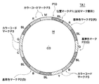
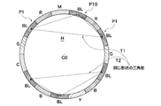
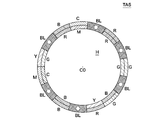
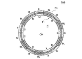
- FIG. 3 is a diagram illustrating an example of a color code target TA1 in Embodiment 1.
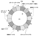
- FIG. 3 is a diagram illustrating an example of a color code target TA2 in the first embodiment.
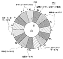
- 6 is a diagram illustrating an example of a color code target TA3 in Embodiment 1.
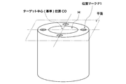
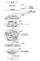
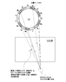
- FIG. It is a figure which shows the relationship between the reference position of a color code target, and a position mark. It is a figure which shows the positional relationship between each position mark. It is a figure which shows the structural example of a color code discrimination device. It is a figure which shows the example of a processing flow of a color code discrimination method. It is explanatory drawing of the gravity center position detection using a retro target.
- FIG. 6 is a diagram illustrating an example of a color code target TA4 in Embodiment 2.
- FIG. 6 is a diagram illustrating an example of a color code target TA5 in Example 3.
- FIG. It is a figure which shows the example of the color code target TA6 in Example 4.
- FIG. It is a figure which shows the example of the color code target TA7 in Example 5.
- FIG. 6 is a diagram illustrating an example of a color code target TA4 in Embodiment 2.
- FIG. 6 is a diagram illustrating an example of a color code target TA5 in Example 3.
- FIG. It is a figure which shows the example of the color code target TA6 in Example 4.
- FIG. It is a figure which shows the example of the color code target TA7 in Example 5.
- [Color code target] 1 to 3 show examples of color code targets TA1 to TA3 in the first embodiment.
- the target is a circular shape, and a circular hole H centered on the reference position C0 is formed at the center, which is the reference position C0, and is positioned along the circumference centered on the reference position C0.
- An example in which the mark P1, the reference color mark P2, and the color code mark P3 are annularly arranged will be described.
- 1 to 3 differ in the radial width of marks arranged in an annular shape along the circumference, but the arrangement of the marks is the same. The width of the ring (ring) is small in FIG. 1, medium in FIG. 2, and large in FIG.
- the position mark P1, the reference color mark P2, and the color code mark P3 are arranged in an annular shape (ring shape) along the circumference centered on the reference position C0.
- a ring formed by connecting marks arranged in a ring along the circumference is called a mark ring (also simply called a ring).
- the color code targets TA1 to TA3 in which the marks are arranged in an annular shape are referred to as ring color targets.
- the position mark P1 is a mark indicating a measurement position
- the reference color mark P2 is a mark provided with a color used as a color reference
- the color code mark P3 is a mark provided with a color for identifying a target.
- the delimiter mark is a mark that delimits between the reference color mark and the color code mark, between the reference color marks, or between the color code marks.
- the position mark P1 also serves as a delimiter mark.
- the first predetermined number is 1 and the second predetermined number is 2.
- the inner diameter of the mark ring is determined by the outer diameter of the probe inserted into the hole and varies depending on the probe. Also, the outer diameter of the mark ring varies depending on the inner diameter. As for the ring, the width of the mark ring is preferably set so that each mark arranged along the circumference can be sufficiently recognized, for example, a width of 1 to 100 mm.
- the outer diameter of the ring is 50 mm and the inner diameter is 45 mm
- the outer diameter of the ring is 60 mm
- the inner diameter is 40 mm
- FIG. 2 and FIG. 3 a plurality of line segment marks or cross marks (which may not be present) toward the center of the circle are seen in the vicinity of the ring, but this is for making it easy to find the center.
- the position mark part is composed of one or a plurality of position marks P1.
- the position mark P1 is a mark for indicating a measurement position.
- the circular opening H is arranged at the center of the circle at the reference position C0
- the position mark P1, the reference color mark P2, and the color code mark P3 are annular along the circumference centered on the reference position C0. It is arranged in a (ring shape).
- the position mark P1 has a small and circular retroreflective function at the center of the black mark (indicated by BL in the figure) (on the symmetry line in the circumferential direction and between the inner and outer diameters in the radial direction). (Retro target) is provided.
- a small retro target preferably has a certain size or more.
- the outer diameter is about half of the radial width of the mark ring.
- the position mark P1 also serves as a delimiter mark.
- the reason for the black background is to clarify the difference from the retro target to facilitate position detection, and to clarify the separation between one or more marks as the separation marks.
- the position mark P1 includes a retro target will be described.
- a small and circular white mark formed by white coating on a black background may be used.
- FIG. 4 shows the relationship between the reference position C0 and the position mark P1 of the color code targets TA1 to TA3.
- the position mark P1, the reference color mark P2, and the color code mark P3 are arranged in an annular shape (ring shape) along the circumference centered on the reference position C0.
- the reference position C0 is located at the center of the circle on the plane including these marks.
- FIG. 5 shows the positional relationship between the position marks P1.
- the position mark P10 positioned above the opening H is counted as the first, and the first triangle T1 connecting the centers of the retro targets of the first, third and thirteenth marks is positioned above the opening H.
- a second triangle T2 connecting the centers of the retro targets of the fifth, eighth and tenth marks is formed counting clockwise from the position mark P10 as the first.
- the shapes of the first triangle T1 and the second triangle T2 are congruent, and the longest side of the first triangle T1 and the longest side of the second triangle T2 are straight lines (in the horizontal direction) that divide the mark ring into upper and lower halves. (Diameter).
- each position mark P1 is arranged in a predetermined positional relationship (a fixed distance, a fixed direction) with respect to the reference position C0. Therefore, the positional relationship (distance and direction) between the first triangle T1 (vertex, side) and the second triangle T2 (vertex, side) is also constant.
- 6 position marks P1 are arranged on the ring.
- DLT Direct Linear Transformation
- 6 points on the ring position mark
- the center point of P1 can be detected with high accuracy.
- the upper three points form the first triangle T1
- the lower three points form the second triangle T2
- the shapes of the first triangle T1 and the second triangle T2 are congruent.
- the longest side of the first triangle T1 and the longest side of the second triangle T2 are arranged to face each other.
- the search is divided into the upper three points and the lower three points rather than searching for six points at once, it is only necessary to search for one triangle, and an efficient search can be performed. For example, if there are 10 candidate points, if 6 points are collectively searched, 2 triangles will be searched from a maximum of 100,000 ways, but if divided into 3 points and 3 points, the search will be 1 from a maximum of 100 ways. One triangle may be searched, and then the corresponding triangle may be searched. Corresponding triangle shapes are congruent, and the longest sides of both faces each other, so the candidate points for the search are considerably narrowed down and can be searched efficiently. The orientation and DLT method will be described later.
- the reference color part is composed of one or a plurality of reference color marks P2.
- the reference color mark P2 is a mark provided with a color to be used as a color reference. In this embodiment, red (indicated by R in the figure), green (indicated by G in the figure), and blue (indicated by B in the figure). Three colors are used.
- both sides are sandwiched between position marks (separation marks) P1, and the position mark P10 located above the opening H is first, and the second, fourth, and ninth positions are counted clockwise. Yes.
- the reference color mark P2 is used for reference during a relative comparison and for color calibration for correcting the color misregistration in order to cope with color misregistration due to photographing conditions such as illumination and a camera.
- the reference color mark P2 can be used for color correction of a color code target created by a simple method. For example, when using a color code target printed by a color printer (inkjet, laser, sublimation type printer, etc.) that is not color-controlled, individual differences appear in the color of the printer used, but the reference color mark P2 By comparing and correcting the color of the color code mark P3, the influence of individual differences can be suppressed. As described above, the color of the reference color mark P2 can be used for correcting the color of the measurement object 2 in addition to correcting the color of the color code mark P3.
- a color printer inkjet, laser, sublimation type printer, etc.
- the color code portion is composed of one or a plurality of color code marks P3.
- the color code mark P3 is a mark provided with a color for identifying the target. In this embodiment, red (indicated by R in the figure), green (indicated by G in the figure), blue (indicated by B in the figure). ), Yellow (indicated by Y in the figure), cyan (indicated by C in the figure), and magenta (indicated by M in the figure).
- Each of the two color code marks P3 is sandwiched between position marks (separation marks) P1 on both sides, and the position mark P10 located above the opening H is counted first in the clockwise direction. , 11, 12th, 14th, 15th.
- the color code mark portion expresses a code by a combination of color schemes of the color code marks constituting the color code mark portion.
- the number of codes that can be expressed varies depending on the number of code colors used for the code. For example, when the number of code colors is n, the color code target TA can represent n n codes when the number of color code marks P3 is n. In order to increase the reliability, even if the condition that the colors used for other unit marks are not used redundantly, n! Express street code. If the number of code colors is increased, the number of codes can be increased. Furthermore, if the condition that the number of color code marks P3 is equal to the number of code colors is imposed, all the code colors are used for the color code mark P3.
- the color of each color code mark P3 can be confirmed to determine the identification code, and the reliability can be improved. Furthermore, adding a condition for making the areas of the respective color code marks P3 the same is also useful when the color code target TA is detected from the image. This is because the area occupied by each color is the same even between color code targets having different identification codes, so that almost the same dispersion value is obtained from the detection light from the entire color code target TA. Further, since the boundary between the color code marks P3 is repeated at equal intervals and a clear color difference is detected, it is possible to detect the color code target TA from the image by repeating such detection light. .
- the mark delimiter is composed of multiple delimiters.
- the delimiter mark is a mark that delimits between the reference color mark P2 and the color code mark P3, between the reference color marks P2 or between the color code marks P3.
- the delimiter mark also serves as the position mark P1. It has a retro target in the center and is black (indicated by BL in the figure).
- each reference color mark P2 is sandwiched between the separator marks P1 on both sides, and two color code marks P3 are sandwiched between the separator marks P1 on both sides, resulting in the first predetermined number. Is 1, and the second predetermined number is 2.
- the delimiter mark P1 is arranged in the first, third, fifth, eighth, tenth, and thirteenth positions when the position mark P10 located above the opening H is counted first and counted clockwise.
- the first, fifth, eighth and tenth division marks counting clockwise from the position mark P10 positioned above the opening H as the first division mark between the reference color mark P2 and the color code mark P3 are 3
- the th delimiter mark is a mark that delimits the reference color marks P2
- the thirteenth delimiter mark is a mark that delimits the color code marks P3.
- a color code target TA1 to TA3 constitutes a set of color code targets
- targets having the same shape and dimensions are used for the color code targets TA1 to TA3.
- an opening H is provided at the center, and the position mark P1, the reference color mark P2, and the color code mark P3 are arranged at the same position on the ring of marks arranged in a ring shape along the circumference.
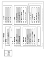
- FIG. 6 shows a configuration example of the color code discrimination device 1.
- the color code discriminating apparatus 1 includes, for example, an imaging unit 3 that captures an image of the measurement object 2, an input / output unit 4 that displays captured images and processed images, and an input / output operation.
- a feature extraction unit 5 that extracts feature points
- a three-dimensional position measurement unit 6 that measures the three-dimensional position and shape of the measurement object 2
- an image processing unit 7 that performs various image processing on the captured image, a captured image, a mark, and a measurement
- a storage unit 8 that stores a position and the like
- a color code determination device 1 and a control unit 9 that controls the respective units and functions as the color code determination device 1 are configured.
- the feature extraction unit 5, the three-dimensional position measurement unit 6, the image processing unit 7, and the control unit 9 can be realized using the functions of the personal computer PC 10 and are configured in the PC 10.
- the photographing unit 3 includes a stereo camera or a single camera for photographing the measurement object 2, and also includes a target image acquisition unit 31 that acquires images of the color code targets TA1 to TA3 from the captured image.
- the target image acquisition unit 31 acquires images from at least two different directions.
- the input / output unit 4 includes a display unit 41 that displays images and operation screens, an output unit 42 that includes a printer, a speaker, and the like, and an input unit 43 that includes a mouse, a keyboard, and the like.
- the feature extracting unit 5 sequentially detects the position mark P1 from the images of the color code targets TA1 to TA3 acquired by the target image acquiring unit 31, and extracts feature points for three-dimensional measurement from the captured image.
- a feature point extraction unit 52 is provided to extract images of the color code targets TA1 to TA3 from the captured image.
- the position mark detection unit 51 sequentially detects the position mark P1 from images acquired from at least two different directions.
- the feature points include, for example, the center position and corner position of the measurement object 2, positions having different characteristics from others, targets attached to or projected on the measurement object 2, and the like. Therefore, the position mark P1 can also be handled as one of the feature points, but here, the position mark detection unit 51 is distinguished as performing a specific process. Therefore, the feature point extraction unit 52 extracts features other than the color code target, for example, feature points for three-dimensional measurement in the measurement object 2.
- the three-dimensional measuring unit 6 searches for a corresponding point corresponding to a feature point in one image (reference image) from a captured image that forms a stereo pair in the other image (search image) (in the case of a color code target, identification is performed).
- a corresponding point search unit 61 that searches for the same corresponding point (such as a retro target of the position mark P1) based on the color code that has been recorded, an orientation unit 62 that obtains the position and inclination of the camera in the stereo image, and a position mark detection
- the reference point calculation unit 63 for obtaining the three-dimensional coordinates of the reference position C0 of the color code targets TA1 to TA3 from the arrangement of the position mark P1 sequentially detected by the unit 51, and the feature points (corresponding to the correspondence points search unit 61)
- a three-dimensional coordinate calculation unit 64 for obtaining the three-dimensional coordinates of the point) and the camera position.
- the position mark can also be handled by including it as a feature point (measurement point), here, the
- the image processing unit 7 sequentially detects marks arranged in a ring shape along the circumference centered on the reference position C0 obtained by the reference position calculation unit 63 and a starting point calculation unit 71 for obtaining a starting point for detecting the mark.
- the color code mark extraction unit 74 that sequentially extracts P3 and the color of each reference color mark P2 extracted by the reference color mark extraction unit 73 are compared with the color of each color code mark P3 extracted by the color code mark extraction unit 74.
- the storage unit 8 stores a captured image storage unit 81 that stores captured images, a reference position C0, and a three-dimensional position storage unit 82 that stores three-dimensional position coordinates of measurement points (including the center of the retro target of the position mark P1).
- a reference color mark storage unit 83 that stores the color data of each reference color mark P2 sequentially extracted by the color mark extraction unit 73, and the color data of each color code mark P3 that is sequentially extracted by the color code mark extraction unit 74 are stored.
- the color code mark storage unit 84 includes a color code storage unit 85 that stores the reference position C0 obtained by the reference position calculation unit 63 and the color code P3 determined by the color code determination unit 75 in association with each other.
- the color code discriminating unit 75 has a color-code correspondence table that records the correspondence between the color data, each reference color, and each color code color, and a plurality of types of color code targets to be used. For TA, the type code number indicating the type of the color code target TA is recorded, and for each color code target TA, the correspondence between the mark arrangement (color arrangement, that is, single color code arrangement) and the target code number is shown. It has a color code target correspondence table to be recorded, and is used for color code discrimination.
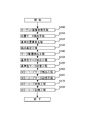
- FIG. 7 shows a processing flow example (outline) of the color code discrimination method for the color code targets TA1 to TA3.
- the target image acquisition unit 31 acquires images of the color code targets TA1 to TA3 (target image acquisition step: S100). In this embodiment, images from at least two different directions are acquired.
- the position mark detection unit 51 sequentially detects the position mark P1 from the images of the color code targets TA1 to TA3 acquired in the target image acquisition step (S100) (position mark detection step: S110). In this embodiment, the position mark P1 is sequentially detected from images acquired from at least two different directions.
- the reference position calculation unit 63 obtains the reference position C0 of the color code targets TA1 to TA3 from the arrangement of the position marks P1 sequentially detected in the position mark detection process (S110) (reference position calculation process: S120). .
- the starting point calculation unit 71 obtains a starting point for detecting the mark from the arrangement of the position marks P1 (starting point calculating step: S130).
- the mark arrangement detection unit 72 sequentially detects marks arranged in an annular shape along the circumference centered on the reference position C0 obtained in the reference position calculation step (S120) (mark arrangement detection). Step: S140).
- the reference color mark extraction unit 73 sequentially extracts the reference color mark P2 from the mark ring detected in the mark arrangement detection step (S140) (reference color mark extraction step: S150), and the reference color mark storage unit.
- the color data of each reference color mark P2 extracted sequentially is stored (reference color mark storage step: S155).
- the color code mark extraction unit 74 sequentially extracts the color code mark P3 from the mark ring detected in the mark arrangement detection step (S140) (color code mark extraction step: S160), and the color code mark storage unit.
- the color data of each color code mark P3 extracted sequentially is stored (color code mark storage step: S165).
- the color code discriminating unit 75 calculates the color of the reference color mark P2 extracted in the reference color mark extraction step (S150) and the color of the color code mark P3 sequentially extracted in the color code mark extraction step (S160). In comparison, the color code is determined from the color arrangement of the color code mark P3 (color code determination step: S170).
- the color code storage unit 85 stores the reference position C0 obtained in the reference position calculation step (S120) and the color code determined in the color code determination step (S170) in association with each other (color code storage). Step: S180).
- the position mark detection step (S110) six position marks P1 arranged on the ring are searched and detected. A retro target or a white target is used at the center of the position mark P1. Since the color code portion P3 of the color code target TA has a feature that a large number of code colors are used and the color dispersion value is large, a portion having a large dispersion value of the color code portion P3 is found from the image. Thus, the color code target TA can be detected. Thereafter, the retro target of the position mark P1 may be detected within the range of the color code target TA. In the reference position mark calculation step (S120), the reference position C0 of the color code targets TA1 to TA3 is obtained from the arrangement of the position marks sequentially detected in the position mark detection step (S110).
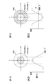
- FIG. 8 is an explanatory diagram of detecting the center of gravity using a retro target.
- the process is the same for a white circular target formed with white paint on a black background instead of a retro target.
- the retro target is formed by two concentric circles, but the outer side is not necessarily a circle.
- FIG. 8A1 the brightness of the inner circle portion 204 that is the inner side of the small circle among the concentric circles is bright, and the brightness of the outer circle portion 206 that is an annular portion formed between the small circle and the great circle is dark.
- the retro target 200, FIG. 8 (A2) is a brightness distribution diagram in the diameter direction of the retro target 200 of (A1), and FIG.
- FIG. 8 (B1) is a retro target in which the brightness of the inner circle portion 204 is dark and the brightness of the outer circle portion 206 is bright.
- 200 and FIG. 8 (B2) show the brightness distribution diagram in the diameter direction of the retro target 200 of (B1).
- the retro target is bright as shown in FIG. 8 (A1), the light intensity distribution of the image is high because the reflected light at the center of gravity is large and bright in the captured image of the measurement object 2.
- FIG. 8A2 it is possible to determine the inner circle portion 204 and the center position of the retro target from the threshold value To of the light amount distribution.
- the small circle which shows a center position is provided in the center of two concentric circles, the small dip has arisen in the center of a brightness distribution map.
- the barycentric position is calculated by, for example, the moment method. For example, assume that the plane coordinates of the retro target 200 shown in FIG. 8A1 are (x, y). Then, (Expression 1) and (Expression 2) are calculated for points in the x and y directions where the brightness of the retro target 200 is greater than or equal to the threshold value To (* is a multiplication operator).
- feature points are extracted by the feature extraction unit 5 (here, the position mark P1 is detected) using images taken from at least two directions as a stereo pair, and are determined by the color code determination unit 75.
- the corresponding point of the code identified by the corresponding point search unit 61 (such as a retro target of the position mark P1) is obtained
- the orientation unit 62 obtains the position and inclination of the camera by orientation
- the 3D position computation unit 64 (Here, the reference position calculation unit 63) obtains the three-dimensional position coordinates.
- a stereo method is typically used to calculate the three-dimensional position coordinates.
- feature points are extracted by the feature extraction unit 5 using images taken with a stereo camera or images taken from at least two directions as stereo pairs.
- the search unit 61 searches for corresponding points
- the orientation unit 62 obtains the position and tilt of the camera by orientation
- the 3D position computation unit 64 obtains 3D position coordinates.
- FIG. 9 shows an example of a processing flow mainly for detecting the mark arrangement of the color code target.
- FIG. 5 for the mark arrangement detection. Please refer to FIG. 7 in a timely manner.
- S210 all candidates for the position mark P1 of the color code targets TA1 to TA3 are detected (S210).
- the coordinates of the position mark P1 are detected by a small circular retro target at the center.
- the range is not limited to one color code target TA, and all measured ranges are detected.
- This step corresponds to the position mark detection step (S110). Details of this step are as described in FIG.
- all triangles (candidates for the first triangle T1 and the second triangle T2) are detected from the position mark candidates detected in (S210) (S220).
- the candidates for the triangles to be obtained are determined. Exclude those that do not. If it can be regarded as a candidate of the triangle (first triangle T1 or second triangle T2) to be obtained from the length of the sides of the triangle and the angle formed by the two sides, the candidate of the first triangle T1 or the second triangle T2 And decide. Subsequently, from the triangles (candidates T1 and T2) detected in (S220), the corresponding triangles (the shapes are congruent and have the longest sides facing each other) are detected, and the color code target (ring color code) is detected.
- the positional relationship between the first triangle T1 (vertex, side) and the second triangle T2 (vertex, side) is also a fixed relationship (distance and direction (direction)). If it can be regarded as the first triangle T1 and the corresponding second triangle T2 to be obtained from this relationship, 6 as the center of the position mark P1 located at the apex of the formed first triangle T1 and second triangle T2. Detect points.
- the positions of the six points at the center of the position mark P1 are confirmed by using the single photograph orientation or the DLT method or by combining the DLT method and the bundle adjustment (S240).
- This step corresponds to the latter stage of the reference position calculation step (S120). It is confirmed whether or not the six points detected as the center of the position mark P1 of the color code target TA are arranged at the designed position of the color code target (ring color code target) TA, and whether or not the triangle is to be obtained. Confirm.
- the calculation of the DLT method and the bundle adjustment is performed by, for example, the three-dimensional position calculation unit 64, and the reference position calculation unit 63 obtains the calculation result.
- the three-dimensional DLT (Direct Linear Transformation) method is a method of reconstructing the positions of marks measured from various directions into three-dimensional coordinates using two or more cameras based on the principle of triangulation.
- the DLT method approximates the relationship between the photograph coordinates and the three-dimensional coordinates (target point coordinates) of the subject by a cubic projective transformation equation.
- the basic expression of the DLT method is (Expression 3-1). If the denominator is deleted from (Equation 3-1), the following line form can be derived.
- equation 3-3 By solving (Equation 3-3) directly using the least square method, eleven unknown variables L 1 to L 11 that determine the relationship between the photographic coordinates and the target point coordinates can be acquired.
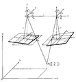
- FIG. 10 is a diagram for explaining confirmation of the position mark P1 by the DLT method.
- eleven unknown variables L 1 to L 11 are known, the relationship between the photographic coordinates (x, y) (CCD plane) and the object point coordinates (X, Y, Z) is known, and the photographic coordinates (x, The position and direction (0, 0, 0, ⁇ , ⁇ , ⁇ ) of the camera on the line connecting y) and the target point coordinates (X, Y, Z) are obtained.
- the position mark P1 is known from the design data (there are six points on the ring), so the color code target TA (ring color code target) obtained for the six points detected as the position mark P1. ) Can be determined.
- a model image refers to a three-dimensional image obtained when a subject is reproduced from two or more three-dimensional photographs. Forming relatively similar model images is called relative orientation. That is, the relative orientation determines the position and inclination of the projection center of each of the left and right cameras so that two corresponding light beams of the stereoscopic photograph meet.
- FIG. 11 is a diagram for explaining relative orientation. Next, the details of the orientation calculation of each model image will be described. By this calculation, the positions of the left and right cameras (three-dimensional coordinates and three-axis tilt) are obtained. The parameters relating to the positions of these cameras are obtained by the following coplanar conditional expression.
- the origin of the model coordinate system is taken as the left projection center, and the line connecting the right projection centers is taken as the X axis.
- the base line length is taken as the unit length.
- the parameters to be obtained at this time are the rotation angle ⁇ 1 of the left camera, the rotation angle ⁇ 1 of the Y axis, the rotation angle ⁇ 2 of the right camera, the rotation angle ⁇ 2 of the Y axis, and the rotation of the X axis. the five of the rotation angle of the corner ⁇ 2. In this case, since the rotation angle ⁇ 1 of the X axis of the left camera is 0, it is not necessary to consider.
- unknown parameters are obtained by the following procedure.
- the bundle adjustment is performed in order to appropriately match the position coordinates of the measurement points between the plurality of captured images.
- the collinear conditional expression that is a basic expression for bundle adjustment that the projection center, the photographic image, and the measurement object are in a straight line is as follows.
- the starting point calculating unit 71 determines a starting point for detecting the mark from the arrangement of the position marks P1.
- the position mark P10 that belongs to the first triangle T1 connecting the position marks P1 and is located above the opening H can be determined as the detection starting point.
- the starting point is not limited to the position mark P10 located above the opening H.
- the position mark P10 located above the opening H, which is located to the right of the reference position C0 is counted 4 in the clockwise direction.
- the second reference color mark may be used as the starting point.
- the color code target (ring color code target) TA1 to TA3 is to be obtained from the detected color arrangement of the ring, and the reference color and the color code color are compared (S250).
- This process extends from the mark arrangement detection process (S140) to the color code mark storage process (S165).
- the mark arrangement detection step (S140) marks arranged in an annular shape along the circumference centered on the reference position C0 are sequentially detected. For example, the position mark P10 located above the aperture H is scanned as a detection starting point, and the color data of the reference color mark P2, the color code mark P3, and the position mark P1 arranged on the ring is collected. To do.
- the position coordinates of the reference color mark P2 and the color code mark P3 are converted according to the design values of the color code targets TA1 to TA3 (for example, affine conversion). And ask. Then, it is checked whether or not the obtained positions of the reference color mark P2 and the color code mark P3 are colored as designed.
- the reference color mark P2 is the position mark P10 located above the opening H, and the position mark P10 is counted as the first, and the second, fourth, and ninth marks are red, green, and blue as position marks.
- the color code mark P3 is sandwiched between P1, and the color code mark P3 is counted in the sixth, seventh, eleventh, twelfth, fourteenth, fifteenth, six colors, counting clockwise from the position mark P10 positioned above the opening H.
- Two marks are arranged so as to be sandwiched between position marks P1 as separation marks.
- the arrangement of the colors (six colors) of the color code mark P3 changes variously. Therefore, in the reference color mark extraction step (S150), the position mark P10 located above the aperture H is counted as the first from the color data collected by scanning the ring, and the second, fourth, and ninth positions are counted clockwise. Are sequentially extracted.
- the color data of each reference color mark P2 extracted sequentially is stored in the reference color mark storage unit 83. Further, in the color code mark extraction step (S160), the position mark P10 located above the aperture H is counted first from the color data collected by scanning the ring and counted 6, 7, 11, The 12th, 14th, and 15th color data are sequentially extracted. In the color code mark storage step (S165), the color data of each color code mark P3 extracted sequentially is stored in the color code mark storage unit 84. The scan route is collated with the converted position data (for example, affine transformation).
- the collected color data is the color of the reference color mark P2, color code mark P3, and position mark P1 of the color code targets TA1 to TA3. It can be determined that the data. The determination is made, for example, after the color code is extracted in the color code mark extraction step (S160). Further, the hue distance of the reference color of the reference color mark P2 is compared and checked. Further, the hue distances of the six colors of the color code mark P3 are compared and checked. In this way, it is checked whether or not the color code targets TA1 to TA3 (ring color code targets) to be obtained from these color schemes. If they are different, the process returns to (S230) to check another triangle. If it is determined that the color code targets TA1 to TA3 are to be obtained, the process proceeds.
- the color code is determined (S260). This step corresponds to the color code discrimination step (S170).
- a code is read from the color scheme of the color code mark P3 to determine the color code.
- the color code discriminating unit 75 counts the color data (hue, hue) of the sixth, seventh, eleventh, twelfth, fourteenth and fifteenth color code marks P3 counting clockwise from the position mark P10 positioned above the opening H as the first. Saturation, lightness) is counted clockwise with the position mark P10 positioned above the aperture H as the first color data (hue, saturation, lightness) of the second, fourth, and ninth reference color marks P2.
- each color code mark P3 is red, yellow, green, cyan, blue, or magenta.
- all code colors are used for the color code mark P3. Therefore, not only the comparison with the reference color mark P2, but also the color code. Reliability can be improved by relatively comparing colors between the marks P3.
- the color of the reference color mark P2 can be used for correcting the color of the measurement object 2 in addition to correcting the color of the color code mark P3.
- the color code determination unit 75 converts the color data into a color code using the color-code correspondence table and the color code target correspondence table.
- the color array data is converted into a color code.
- labeling is performed (S270).
- This step corresponds to the color code storing step (S180). That is, the determined color code is stored in the color code storage unit 85 in association with the reference position (center) C0 of the color code targets TA1 to TA3 (S270). As a result, the color code is attached to the reference position of the color code targets TA1 to TA3 as a label. If other triangle combinations (candidates for T1 and T2) to be searched remain, the process returns to (S230), and these combinations are similarly processed. This substantially searches for the other color code targets TA1 to TA3. If not, complete the process.
- the hole when the hole is provided at the center of the color code target, it is easy to measure the reference position of the target, and the color code mark can be easily detected and the color code can be easily distinguished.
- a color code determination apparatus and a color code determination method suitable for determining the color code of the color code target can be provided.
- FIG. 12 shows an example of the color code target TA4 in the second embodiment.
- Example 1 there was one ring (ring), but Example 2 shows an example in which the ring is double.
- the inner ring is the same as in Example 1, but another ring is provided on the outer side.
- the arrangement of the reference color mark P2 and the color code mark P3 in the circumferential direction is the same as that of the inner ring, and the color arrangement order of the color code mark P3 is changed.
- the reference position C0 and the opening H are the same as those in the first embodiment, and when the opening is provided at the center of the color code target, it is easy to measure the reference position of the target. It is possible to provide a color code target that can be easily discriminated.
- FIG. 13 shows an example of the color code target TA5 in the third embodiment.
- the position mark P1 is provided on the inner ring, but in the third embodiment, the position mark P1 is provided across the inner and outer rings.
- the position mark P1 can be enlarged and easily detected.
- the arrangement of the position mark P1, the reference color mark P2, and the color code mark P3 is the same as in Example 2, and when the hole is provided at the center of the color code target, the measurement of the reference position of the target is easy.
- a color code target that can easily detect a color code mark and determine a color code can be provided.
- FIG. 14 shows an example of the color code target TA6 in the fourth embodiment.
- two circular rings are separated by a black region. Thereby, two circular rings can be clearly distinguished. Therefore, it is possible to reduce errors in the circular scan.
- the arrangement of the position mark P1, the reference color mark P2, the color code mark P3, and the delimiter mark P4 is the same as that in the second embodiment, and when the hole is provided at the center of the color code target, the reference position of the target is measured. It is easy to provide a color code target that can easily detect a color code mark and distinguish a color code.
- FIG. 15 shows an example of the color code target TA7 in the fifth embodiment.
- the position mark P1 is provided on the inner ring, but in the fifth embodiment, the position mark P1 is provided across the inner and outer rings.
- the position mark P1 can be enlarged and easily detected.
- the arrangement of the position mark P1, the reference color mark P2, and the color code mark P3 is the same as in Example 2, and when the hole is provided at the center of the color code target, the measurement of the reference position of the target is easy.
- a color code target that can easily detect a color code mark and determine a color code can be provided.
- the marks are annularly arranged along the circumference centered on the reference position.
- the marks may be annularly arranged along the outer periphery of the regular polygon.
- the reference color is 3 colors and the color code color is 6 has been described, but it is sufficient that the reference color is 1 color or more and the color code color is 2 colors or more, and the number of reference color marks is 1 or more.
- the number of color code marks may be one or more. When the number of color code marks is 1, the reference color mark and the color code mark can be distinguished from each other by changing the circumferential or radial width. The greater the number of color code colors, the greater the number of codes that can be used.
- the reference number of colors typically uses three primary colors of light, but can be changed according to the number of color code colors.
- the number of mark rings is single or double has been described, but it may be triple or more.
- the greater the number of rings the greater the number of codes that can be used, and the smaller the number, the simpler the configuration and the easier the processing.
- the reference color mark may be arranged in the inner ring and the color code mark may be arranged in the outer ring for distinction.
- the opening H is described as being inscribed in the mark ring.
- the color code target may have an inner frame region between the mark ring and the opening. The outer frame region may be provided outside the mark ring.
- the center of the opening is the reference position and coincides with the center of the color code target. However, it may be decentered to some extent from the center of the color code target.
- two triangles with congruent arrangement of position marks can be extracted has been described.
- two inverted symmetrical triangles may be extracted.
- two triangles corresponding to a plurality of color code targets in the measurement range may be extracted.
- the color code identification device may have a simplified configuration by omitting, for example, the input unit, the output unit, the starting point calculation unit, the corresponding point search unit, the orientation unit, and the like.
- the order of the steps can be changed. For example, the collection of color data from the mark ring may be performed before the calculation of the starting point. After the mark arrangement detection step, the mark extraction step You may collect again.
- the example in which the determination whether the color data collected by scanning on the ring matches the design data is performed in the color code mark extraction process, but in the mark arrangement detection process.
- Color data may be collected and performed. Either the reference color mark extraction step or the color code mark extraction step may be performed first.
- the outer shape of the mark (4, 6, octagonal shape, etc.), the number of marks sandwiched between the separator marks, the number of color code colors, the number of color code marks, and the like can be appropriately changed.
- the present invention is used for various three-dimensional measurements.
- it is used for three-dimensional measurement in which multi-point measurement is performed by providing an aperture through which a prober or the like is passed.
Landscapes
- Physics & Mathematics (AREA)
- General Physics & Mathematics (AREA)
- Engineering & Computer Science (AREA)
- Radar, Positioning & Navigation (AREA)
- Remote Sensing (AREA)
- Length Measuring Devices By Optical Means (AREA)
Abstract
中心に開孔を設ける場合に、ターゲットの基準位置の測定が容易であり、マークの検出及びカラーコードの判別が容易であるカラーコードターゲットを提供する。本発明のカラーコードターゲットTA1は、計測位置を示すための位置マークP1からなる位置マーク部と、色彩の基準として用いる基準色マークP2からなる基準色部と、当該カラーコードターゲットTA1を識別するためのカラーコードマークP3からなるカラーコード部と、マーク間を区切る区切マークからなるマーク区切部とを面内に備え、位置マークP1と基準色マークP2とカラーコードマークP3が、基準位置C0を中心とする円周に沿って環状に配置され、基準位置C0には開孔Hが設けられ、区切マークは、第1の所定数の基準色マークP2を挟み、第2の所定数のカラーコードマークP3を挟むように配置される。
Description
本発明は、カラーコードターゲット、カラーコード判別装置及びカラーコード判別方法に関する。詳しくは、自他識別可能なカラーコードマークが環状に配置されたカラーコードターゲット、かかるカラーコードターゲットのカラーコード判別装置及びカラーコード判別方法に関する。
カラーコードターゲットとは、三次元計測のために発明者達により提案されたターゲットで、面内に、計測位置を示すための位置マークと、ターゲットを識別するための色彩が施されたカラーコードマークとを備える。三次元計測に用いるターゲットを個々に識別できるようにし、これにより撮像から三次元計測までの工程の全自動化に寄与するようにしたものである(特許文献1参照)。また、カラーコードターゲットのカラーコードを判別するための装置及び方法も発明者達により提案された(特許文献2参照)。これらのカラーコードターゲット、カラーコード判別装置及びカラーコード判別方法は、ターゲットを個々に識別可能であるという特徴を活かして、様々な対象物の三次元計測に用いられてきた。特に広大な対象物、複雑な形状の対象物など、多数のターゲットを要する三次元計測において、コンピュータによる自動処理に適しており、効率の良い計測が可能となっている。
しかしながら、科学や医療の分野ではプローブ位置を測定したい場合があり、例えばEEG(脳波:electroencephalogram)やfNIRS(機能的NIRS:functional near-infrared spectroscopy)では検出用のプローブを被検者の頭部に多数取り付け、様々な刺激に対する脳波の反応や、脳機能の活性度分布等を測定する。その際に多数のプローブの位置を高精度に測定するために、個々のターゲットを識別できるカラーコードターゲットを使用したいのであるが、プローブの位置を避けてターゲットを配置する必要がある。そこで、ターゲットの中心にプローブを挿入可能な開孔を設け、その周囲に位置マーク及びカラーコードマークを配置することが考えられるが、その場合に、プローブの位置すなわちターゲットの中心(基準位置)をどのように計測するか、位置マーク及びカラーコードマークをどのように配置し、どのように検出すべきか等が未解決であった。
本発明は、カラーコードターゲットの中心に開孔を設ける場合に、ターゲットの基準位置の測定が容易であり、位置マークとカラーコードマークの検出及びカラーコードの判別が容易であるカラーコードターゲットを提供することを目的とする。また、かかるカラーコードターゲットのカラーコードの判別に適するカラーコード判別装置及びカラーコード判別方法を提供することを目的とする。
上記課題を解決するために、本発明の第1の態様に係るカラーコードターゲットTA1~TA3は、例えば図1~図3に示すように、計測位置を示すための位置マークP1からなる位置マーク部と、色彩の基準として用いる色彩が施された基準色マークP2からなる基準色部と、当該カラーコードターゲットTA1~TA3を識別するための色彩が施されたカラーコードマークP3からなるカラーコード部と、基準色マークP2とカラーコードマークP3の間、基準色マークP2同士の間又はカラーコードマークP3同士の間を区切る区切マークからなるマーク区切部とを面内に備え、位置マークP1と基準色マークP2とカラーコードマークP3が、基準位置C0を中心とする円周又は正多角形の外周に沿って環状に配置され、基準位置C0には開孔Hが設けられ、区切マークは、第1の所定数の基準色マークP2を挟み、第2の所定数のカラーコードマークP3を挟むように配置される。
ここにおいて、カラーコードターゲットTA1~TA3に含まれる位置マークP1、基準色マークP2、カラーコードマークP3は単数でも複数でも良い。また、位置マークP1は区切マークを兼用しても良い。また、位置マークP1には典型的にはレトロターゲットを含むマークが用いられるが、位置(点)を特定できれば、テンプレートマーク等他のマークでも良い。基準色マークP2には典型的には、赤(R)、緑(G)、青(B)の光三原色が使用されるが、色相差が均等であれば他の色彩でも良い。また、カラーコードマークP3はそれぞれ色彩を有し、カラーコード部はこれを構成する単数又は複数のカラーコードマークP3の色彩の配置(配列を含む)の差異により識別性を有する。カラーコードマークP3の色彩には基準色マークP2の色彩を含めるのが判別を容易、確実にするので好ましいが、その他の色彩だけを用いても良い。また、カラーコードマークP3に使用する色彩の色相差を均等になるよう選択するのが使用する色彩間の差異を明確にする上で好ましい。また、各マークの円周方向の幅を同一にするとマーク検出のスキャン時間が同じになり、マークの位置を検出するのに便宜であるが、例えばマーク間の区切りを明確にできれば区切マークの幅を小さくしても良い。また、マークが環状に配置されとは、基準位置C0の周りを円周方向に一周して配置されれば、円環状に限られず多角形環状に配置されても良い。また、円周又は正多角形の外周に沿って環状に配置されたマークを連ねて構成される環をマークの環と称する。そして、開孔Hは典型的にはマークの環に内接して配置されるが、カラーコードターゲットはマークの環と開孔Hの間に内枠領域を有しても良く、マークの環の外側に外枠領域を有しても良い。
本態様のように構成すると、位置マークP1が基準位置C0を中心とする円周等に沿って環状に配置されるので、基準位置C0を位置マークP1を結ぶ円等の中心として容易に求めることができる。また、位置マークP1としてレトロターゲットを含むマークを円環等上の定位置に所定の位置関係で配置することにより位置マークP1の検出が容易になる。また、基準色マークP2を用いてカラーコードマークP3の色彩の判別を正確かつ容易にできる。また、区切マークを用いて基準色マークP2とカラーコードマークP3を区切り、それぞれを円環等上の定位置に配置することにより基準色マークP2とカラーコードマークP3の検出が容易になる。したがって、カラーコードターゲットTA1~TA3の中心に開孔Hを設ける場合に、ターゲットの基準位置C0の測定が容易であり、位置マークP1とカラーコードマークP3の検出及びカラーコードの判別が容易であるカラーコードターゲットを提供することができる。
また、第2の態様に係るカラーコードターゲットTA1~TA3は、第1の態様において、例えば図1~図3に示すように、位置マークP1は区切マークを兼ねる。
このように構成すると、区切マークを改めて設ける必要がなく、その分、位置マークP1、基準色マークP2やカラーコードマークP3を大きくでき、これらのマークを検出し易くなる。
このように構成すると、区切マークを改めて設ける必要がなく、その分、位置マークP1、基準色マークP2やカラーコードマークP3を大きくでき、これらのマークを検出し易くなる。
また、第3の態様に係るカラーコードターゲットTA1~TA3は、第1又は第2の態様において、例えば図1~図3に示すように、第1の所定数は1であり、第2の所定数は2以上の定数である。
このように構成すると、区切マークに挟まれる基準色マーク数とカラーコードマーク数を異にすることにより、基準色マークP2とカラーコードマークP3を容易に区別できる。
このように構成すると、区切マークに挟まれる基準色マーク数とカラーコードマーク数を異にすることにより、基準色マークP2とカラーコードマークP3を容易に区別できる。
また、第4の態様に係るカラーコードターゲットTA1~TA3は、第1ないし第3のいずれかの態様において、例えば図1~図3に示すように、カラーコードマークP3のマーク数とカラーコードに用いる色彩の数とが一致し、カラーコード部を構成する各カラーコードマークP3の色彩が全て異なる。
このように構成すると、全てのコード色がカラーコードマークP3に使用されるため、基準色マークP2との比較のみで無く、各カラーコードマークP3間で色彩を相対比較することにより、各マークの色彩を確認して識別コードを決定することができ、カラーコード判別の信頼性を上げることができる。
このように構成すると、全てのコード色がカラーコードマークP3に使用されるため、基準色マークP2との比較のみで無く、各カラーコードマークP3間で色彩を相対比較することにより、各マークの色彩を確認して識別コードを決定することができ、カラーコード判別の信頼性を上げることができる。
また、第5の態様に係るカラーコードターゲットTA1~TA3は、第1ないし第4のいずれかの態様において、例えば図1~図3に示すように、基準色マークP2とカラーコードマークP3は基準位置C0に対して所定の位置関係に配置される。
ここにおいて、所定の位置関係とは典型的には基準位置C0からの距離及び方向が一定の距離、一定の方向にあることをいう。本態様のように構成すると、基準色マークP2とカラーコードマークP3は円環等上の定位置に配置されるので、これらの検出が容易になる。
ここにおいて、所定の位置関係とは典型的には基準位置C0からの距離及び方向が一定の距離、一定の方向にあることをいう。本態様のように構成すると、基準色マークP2とカラーコードマークP3は円環等上の定位置に配置されるので、これらの検出が容易になる。
また、第6の態様に係るカラーコードターゲットTA1~TA3は、第1ないし第5のいずれかの態様において、例えば図1~図3に示すように、位置マークP1は少なくとも6個で構成され、位置マークP1の中心を結んで形成される三角形の中から、合同又は反転対称な2つの三角形を抽出できるように配置される。
ここにおいて、位置マークが7以上であっても、2つの三角形を抽出できれば良い。本態様のように構成すると、位置マークP1の中心(レトロターゲットの位置)を結ぶと合同又は反転対称な2つの三角形を抽出できるので、計測中のカラーコードターゲットTA1~TA3において、三角形を形成した点が求めるべき位置マークP1のレトロターゲットであるか否かを容易に判断できる。
ここにおいて、位置マークが7以上であっても、2つの三角形を抽出できれば良い。本態様のように構成すると、位置マークP1の中心(レトロターゲットの位置)を結ぶと合同又は反転対称な2つの三角形を抽出できるので、計測中のカラーコードターゲットTA1~TA3において、三角形を形成した点が求めるべき位置マークP1のレトロターゲットであるか否かを容易に判断できる。
また、第7の態様に係るカラーコードターゲットTA1~TA3は、第1ないし第6のいずれかの態様において、例えば図1~図3に示すように、円周又は正多角形の外周に沿って環状に配置されるマークの環は単数である。
このように構成すると、計測点が比較的少ない場合に(例えば720点以下)、構成が簡素なカラーコードターゲットを使用でき、マーク検出及びコード判別の処理が簡素になり、適切である。
このように構成すると、計測点が比較的少ない場合に(例えば720点以下)、構成が簡素なカラーコードターゲットを使用でき、マーク検出及びコード判別の処理が簡素になり、適切である。
また、第8の態様に係るカラーコードターゲットTA4~7は、第1ないし第6のいずれかの態様において、例えば図12~図15に示すように、円周又は正多角形の外周に沿って環状に配置されるマークの環は複数であり、各マークの環はいずれも基準位置C0を中心とする。
このように構成すると、計測点が比較的多い場合に(例えば720点より多い)、識別可能なコード数を乗算的に増加でき(2重環の場合、第1の環のコード数がA、第2の環のコード数がBのとき、全体のコード数はA×Bとなる、3重環の場合は全体のコード数はさらに多くなる)、適切である。
このように構成すると、計測点が比較的多い場合に(例えば720点より多い)、識別可能なコード数を乗算的に増加でき(2重環の場合、第1の環のコード数がA、第2の環のコード数がBのとき、全体のコード数はA×Bとなる、3重環の場合は全体のコード数はさらに多くなる)、適切である。
また、第9の態様に係るカラーコードターゲットTA1~TA3は、第7又は第8の態様において、例えば図1~図3に示すように、1つのマークの環上に配置される位置マークP1と基準色マークP2とカラーコードマークP3は同じ形状及び寸法で統一されている。
このように構成すると、円環等上に配置される各マークの形状及び寸法が等しいので、各マークの検出が容易かつ確実になる。
このように構成すると、円環等上に配置される各マークの形状及び寸法が等しいので、各マークの検出が容易かつ確実になる。
また、第10の態様に係る1組のカラーコードターゲットは、第1ないし第9のいずれかの態様のカラーコードターゲットTAを複数組み合わせて構成される1組のカラーコードターゲットであって、各カラーコードターゲットTAは、位置マークP1、基準色マークP2及びカラーコードマークP3がマークの環上の同一位置に配置され、基準色マークP2の色彩の配置が同一であり、カラーコードマークP3の色彩の配置が全て異なるように構成される。
このように構成すると、1組のカラーコードターゲットを構成する各カラーコードターゲットTAは、カラーコードマークP3の色彩の配置のみが異なるので、同一の処理手順でカラーコードの判別が可能であり、カラーコード判別処理の自動化に適している。なお、符号TAは本発明に係るカラーコードターゲットを総称的に示す場合に使用される。
このように構成すると、1組のカラーコードターゲットを構成する各カラーコードターゲットTAは、カラーコードマークP3の色彩の配置のみが異なるので、同一の処理手順でカラーコードの判別が可能であり、カラーコード判別処理の自動化に適している。なお、符号TAは本発明に係るカラーコードターゲットを総称的に示す場合に使用される。
また、第11の態様に係るカラーコード判別装置1は、例えば図6に示すように、少なくとも異なる2方向から第1の態様に係るカラーコードターゲットTA1~TA3の画像を取得するターゲット画像取得部31と、ターゲット画像取得部31で少なくとも異なる2方向から取得されたカラーコードターゲットTA1~TA3の画像からそれぞれ位置マークP1を順次検出する位置マーク検出部51と、位置マーク検出部51でそれぞれ順次検出された位置マークP1の配置からカラーコードターゲットTA1~TA3の基準位置C0を求める基準位置算定部63と、基準位置算定部63で求められた基準位置C0を中心とする円周又は正多角形の外周に沿って環状に配置されたマークを順次検出するマーク配置検出部72と、マーク配置検出部72で検出されたマークの環から基準色マークP2を順次抽出する基準色マーク抽出部73と、マーク配置検出部72で検出されたマークの環からカラーコードマークP3を順次抽出するカラーコードマーク抽出部74と、基準色マーク抽出部73で抽出された各基準色マークP2の色彩とカラーコードマーク抽出部74で抽出された各カラーコードマークP3の色彩を比較して、カラーコードマークP3の色彩の配置からカラーコードを判別するカラーコード判別部75と、基準位置算定部63で求められた基準位置C0とカラーコード判別部75で判別されたカラーコードとを対応付けて記憶するカラーコード記憶部85とを備える。
ここにおいて、マークの環から順次抽出するとは、マークの環の指定された又は設計で定められた位置から配列順に抽出することをいう。また、色彩の比較は典型的には光三原色の検出光の強度比で比較するが、スペクトルを比較しても良い。本態様のように構成すると、位置マーク検出部51にて基準位置C0を中心とする円周等に沿って環状に配置された位置マークP1を検出し、基準位置算定部63にて位置マークP1から基準位置C0を求めるので、基準位置C0を位置マークP1を結ぶ円等の中心として容易に求めることができる。また、基準色マーク抽出部73及びカラーコードマーク抽出部74にて環状に配置された基準色マークP2及びカラーコードマークP3を抽出し、カラーコード判別部75にてこれらのマークの色彩を比較してカラーコードを判別するので、カラーコードを正確かつ容易に判別することができる。したがって、本発明に係るカラーコードターゲットTAのカラーコードの判別に適したカラーコード判別装置を提供することができる。
また、第12の態様に係るカラーコード判別装置1は、第11の態様において、例えば図6に示すように、位置マーク検出部51で順次検出された位置マークP1の配置に基づいてマーク配置検出部72で環状に配置されたマークを検出する起点を求める起点算定部71を備え、マーク配置検出部72は起点算定部71で求められた起点からマークを順次検出する。
このように構成すると、マーク検出の起点と順序を容易に決められ、効率的なマーク検出ができる。また、この起点はカラーコードマークの配列の起点としても使用できる。
このように構成すると、マーク検出の起点と順序を容易に決められ、効率的なマーク検出ができる。また、この起点はカラーコードマークの配列の起点としても使用できる。
また、第13の態様に係るカラーコード判別方法は、例えば図7に示すように、少なくとも異なる2方向から第1の態様に係るカラーコードターゲットの画像を取得するターゲット画像取得工程(S100)と、ターゲット画像取得工程(S100)で少なくとも異なる2方向から取得されたカラーコードターゲットTA1~TA3の画像からそれぞれ位置マークP1を順次検出する位置マーク検出工程(S110)と、位置マーク検出工程(S110)でそれぞれ順次検出された位置マークP1の配置からカラーコードターゲットTA1~TA3の基準位置C0を求める基準位置算定工程(S120)と、基準位置算定工程(S120)で求められた基準位置C0を中心とする円周又は正多角形の外周に沿って環状に配置されたマークを順次検出するマーク配置検出工程(S140)と、マーク配置検出工程(S140)で検出されたマークの環から各基準色マークP2を順次抽出する基準色マーク抽出工程(S150)と、マーク配置検出工程(S140)で検出されたマークの環からカラーコードマークP3を順次抽出するカラーコードマーク抽出工程(S160)と、基準色マーク抽出工程(S150)で抽出された各基準色マークP2の色彩とカラーコードマーク抽出工程(S160)で抽出された各カラーコードマークP3の色彩を比較して、カラーコードマークP3の色彩の配置からカラーコードを判別するカラーコード判別工程(S170)と、基準位置算定工程(S120)で求められた基準位置C0とカラーコード判別工程(S170)で判別されたカラーコードとを対応付けて記憶するカラーコード記憶工程(S180)とを備える。
本態様のように構成すると、位置マーク検出工程(S110)にて基準位置C0を中心とする円周等に沿って環状に配置された位置マークP1を検出し、基準位置算定工程(S120)にて位置マークから基準位置C0を求めるので、基準位置C0を位置マークP1を結ぶ円等の中心として容易に求めることができる。また、基準色マーク抽出工程(S150)及びカラーコードマーク抽出工程(S160)にて環状に配置された基準色マークP2及びカラーコードマークP3を抽出し、カラーコード判別工程(S170)にてこれらのマークの色彩を比較してカラーコードを判別するので、カラーコードを正確かつ容易に判別することができる。したがって、本発明に係るカラーコードターゲットTAのカラーコードの判別に適したカラーコード判別方法を提供することができる。
また、第14の態様に係るカラーコード判別方法は、第13の態様において、例えば図7に示すように、位置マーク検出工程で順次検出された位置マークP1の配置に基づいてマーク配置検出工程(S140)で環状に配置されたマークを検出する起点を求める起点算定工程(S130)を備え、マーク配置検出工程(S140)は起点算定工程(S130)で求められた起点からマークを順次検出する。
このように構成すると、マーク検出の起点と順序を容易に決められ、効率的なマーク検出ができる。
このように構成すると、マーク検出の起点と順序を容易に決められ、効率的なマーク検出ができる。
本発明によれば、カラーコードターゲットの中心に開孔を設ける場合に、ターゲットの基準位置の測定が容易であり、位置マークとカラーコードマークの検出及びカラーコードの判別が容易であるカラーコードターゲットを提供できる。また、かかるカラーコードターゲットのカラーコードの判別に適するカラーコード判別装置及びカラーコード判別方法を提供できる。
この出願は、日本国で2009年8月31日に出願された特願2009-200901号に基づいており、その内容は本出願の内容として、その一部を形成する。本発明は以下の詳細な説明によりさらに完全に理解できるであろう。本発明のさらなる応用範囲は、以下の詳細な説明により明らかとなろう。しかしながら、詳細な説明及び特定の実例は、本発明の望ましい実施の形態であり、説明の目的のためにのみ記載されているものである。この詳細な説明から、種々の変更、改変が、本発明の精神と範囲内で、当業者にとって明らかであるからである。出願人は、記載された実施の形態のいずれをも公衆に献上する意図はなく、改変、代替案のうち、特許請求の範囲内に文言上含まれないかもしれないものも、均等論下での発明の一部とする。
以下、図面を参照して、本発明の実施の形態について説明する。尚、各図において、互いに同一又は相当する部分には同一符号を付し,重複した説明は省略する。
[カラーコードターゲット]
図1~図3に実施例1におけるカラーコードターゲットTA1~TA3の例を示す。本実施例では、形状が円形のターゲットであり、基準位置C0である中心には基準位置C0を中心とする円形の開孔Hが開けられ、基準位置C0を中心とする円周に沿って位置マークP1、基準色マークP2、カラーコードマークP3が環状に配置される例を説明する。図1~図3は円周に沿って環状に配置されるマークの半径方向の幅が異なるが、マークの配置は同じである。環(リング)の幅は、図1が小、図2が中、図3が大である。また、位置マークP1、基準色マークP2、カラーコードマークP3が基準位置C0を中心とする円周に沿って環状(リング状)に配置されている。円周に沿って環状に配置されるマークを連ねて形成される環をマークの環(リング)(単に円環ともいう)と称する。また、マークがこのように環状に配置されているカラーコードターゲットTA1~TA3をリングカラーターゲットと称する。位置マークP1は計測位置を示すマーク、基準色マークP2は色彩の基準として用いる色彩が施されたマーク、カラーコードマークP3はターゲットを識別するための色彩が施されたマークである。また、区切マークは基準色マークとカラーコードマークの間、基準色マーク同士の間又はカラーコードマーク同士の間を区切るマークである。この例では位置マークP1が区切マークを兼ねている。また、この例では第1の所定数が1、第2の所定数が2の場合を示す。
図1~図3に実施例1におけるカラーコードターゲットTA1~TA3の例を示す。本実施例では、形状が円形のターゲットであり、基準位置C0である中心には基準位置C0を中心とする円形の開孔Hが開けられ、基準位置C0を中心とする円周に沿って位置マークP1、基準色マークP2、カラーコードマークP3が環状に配置される例を説明する。図1~図3は円周に沿って環状に配置されるマークの半径方向の幅が異なるが、マークの配置は同じである。環(リング)の幅は、図1が小、図2が中、図3が大である。また、位置マークP1、基準色マークP2、カラーコードマークP3が基準位置C0を中心とする円周に沿って環状(リング状)に配置されている。円周に沿って環状に配置されるマークを連ねて形成される環をマークの環(リング)(単に円環ともいう)と称する。また、マークがこのように環状に配置されているカラーコードターゲットTA1~TA3をリングカラーターゲットと称する。位置マークP1は計測位置を示すマーク、基準色マークP2は色彩の基準として用いる色彩が施されたマーク、カラーコードマークP3はターゲットを識別するための色彩が施されたマークである。また、区切マークは基準色マークとカラーコードマークの間、基準色マーク同士の間又はカラーコードマーク同士の間を区切るマークである。この例では位置マークP1が区切マークを兼ねている。また、この例では第1の所定数が1、第2の所定数が2の場合を示す。
マークの環の内径は孔に挿入するプローブ等の外径により定まり、プローブにより様々である。また、マークの環の外径も内径に対応して様々である。また円環については、円周に沿って配置される各マークを充分認識できるようにマークの環の幅をとることが好ましく、例えば幅1~100mmとする。例えば、図1の例として、円環の外径50mm、内径45mm、図2の例として、円環の外径60mm、内径40mm、図3の例として、円環の外径60mm、内径25mmが挙げられる。なお、図2、図3では円環の近傍に円の中心に向かう複数の線分マーク又は十字マーク(無くても良い)が見られるが、これは中心を見付け易くするためのものである。
位置マーク部は単数又は複数の位置マークP1により構成される。位置マークP1は計測位置を示すためのマークである。本実施例では、円形の開孔Hが基準位置C0である円の中心に配置され、位置マークP1、基準色マークP2、カラーコードマークP3が基準位置C0を中心とする円周に沿って環状(リング状)に配置されている。位置マークP1には、黒(図中BLで示す)地のマークの中心(円周方向には対称線上で半径方向には内径と外径の中間)に小型で円形の再帰反射機能を有するターゲット(レトロターゲット)が設けられている。小型のレトロターゲットは位置検出を可能にするため、或る程度以上の寸法とすることが好ましく、例えば外径をマークの環の半径方向の幅の半分程度とする。本実施例では、位置マークP1は区切マークを兼ねている。黒地とするのは、レトロターゲットとの差異を明確にして位置検出を容易にするため、また、区切マークとして、単数又は複数のマーク間の区切を明確にするためである。位置マークP1は6個あり、開孔Hの上方に位置する位置マークP10を1番目として時計回りに数えて1,3,5,8,10,13番目に配置されている。本実施例では、位置マークP1がレトロターゲットを含む例を説明するが、レトロターゲットに代えて、黒地に白の塗装で形成された小型で円形の白色のマークを用いてもよい。
図4にカラーコードターゲットTA1~TA3の基準位置C0と位置マークP1との関係を示す。位置マークP1、基準色マークP2、カラーコードマークP3が基準位置C0を中心とする円周に沿って環状(リング状)に配置されている。円の中心には開孔Hがある。基準位置C0は、これらのマークを含む平面上で、円の中心に位置する。
図5に各位置マークP1間の位置関係を示す。開孔Hの上方に位置する位置マークP10を1番目として時計回りに数えて1,3,13番目のマークのレトロターゲットの中心を結ぶ第1の三角形T1と、開孔Hの上方に位置する位置マークP10を1番目として時計回りに数えて5,8,10番目のマークのレトロターゲットの中心を結ぶ第2の三角形T2が形成されている。第1の三角形T1と第2の三角形T2の形状は合同であり、第1の三角形T1の最長辺と第2の三角形T2の最長辺とはマークの環を上下半分に仕切る直線(水平方向の直径)に対して向かい合うように配置されている。したがって、位置マークP1の検出に際して、かかる関係の2つの三角形T1,T2を見出すことにより、検出が容易になる。なお、合同な三角形の代わりに反転対称の三角形を用いても良い。各位置マークP1は基準位置C0に対して所定の位置関係(一定の距離、一定の方向)に配置される。したがって、第1の三角形T1(頂点、辺)と第2の三角形T2(頂点、辺)との位置関係(距離と方向)も一定になる。
円環(リング)上に6個の位置マークP1が配置されている。これにより、単写真標定又はDLT(Direct Linear Transformation)法、又はDLT法とバンドル調整を併用した方法を用いて、撮影画像上の多数の候補点から円環(リング)上の6点(位置マークP1の中心点)を高精度に検出することができる。これらの6点のうち、上側の3点で第1の三角形T1が、下側の3点で第2の三角形T2が形成され、第1の三角形T1と第2の三角形T2の形状は合同であり、第1の三角形T1の最長辺と第2の三角形T2の最長辺とは向かい合うように配置されている。このため、6点を一括探索するより、上側の3点と下側の3点に分割して探索すると、1つの三角形を探索するだけで良く、効率的な探索ができる。例えば、候補点が10の場合、6点を一括探索すると、最大100,000通りから2つの三角形を探索することになるが、3点・3点に分割して探索すると、最大100通りから1つの三角形の探索を行ない、その後これに対応する三角形を探索すれば良い。対応する三角形の形状は合同であり、両者の最長辺は向かい合っているので、その探索の候補点はかなり絞られ、効率良く探索できる。標定とDLT法については後述する。
基準色部は単数又は複数の基準色マークP2により構成される。基準色マークP2は色彩の基準として用いる色彩が施されたマークであり、本実施例では、赤(図中Rで示す)、緑(図中Gで示す)、青(図中Bで示す)の3色が使用されている。また、ここでは、両側を位置マーク(区切マーク)P1で挟まれており、開孔Hの上方に位置する位置マークP10を1番目として時計回りに数えて2,4,9番目に配置されている。基準色マークP2は、照明やカメラ等の撮影条件による色のズレに対応するために、相対比較時の参照用、色ズレを補正するためのカラーキャリブレーション用として使用される。さらに、基準色マークP2は、簡易な方法で作成されたカラーコードターゲットの色彩補正用として使用できる。例えば、色管理がなされていないカラープリンター(インクジェット・レーザー・昇華型等のプリンタ)で印刷したカラーコードターゲットを使用する場合は、使用プリンタ等で色彩に個体差が出るが、基準色マークP2とカラーコードマークP3の色を相対比較し補正することで、個体差の影響を抑さえることができる。このように、基準色マークP2の色彩はカラーコードマークP3の色彩の補正の他に、測定対象物2の色彩の補正にも使用できる。
カラーコード部は単数又は複数のカラーコードマークP3により構成される。カラーコードマークP3はターゲットを識別するための色彩が施されたマークであり、本実施例では、赤(図中Rで示す)、緑(図中Gで示す)、青(図中Bで示す)、黄(図中Yで示す)、シアン(図中Cで示す)、マゼンタ(図中Mで示す)の6色が使用されている。また、それぞれ2個のカラーコードマークP3がその両側を位置マーク(区切マーク)P1で挟まれており、開孔Hの上方に位置する位置マークP10を1番目として時計回りに数えて6,7番目、11,12番目、14,15番目に配置されている。カラーコードマーク部は、これを構成する各カラーコードマークの配色の組み合わせによってコードを表現する。コードに使用するコード色の数により表現可能なコード数が変化する。例えば、コード色数がnの場合、カラーコードターゲットTAでは、カラーコードマークP3がn個のとき、nn通りのコードを表せる。信頼度を上げるため、他の単位マークに使用されている色を重複して使用しないという条件を課した場合でも、n!通りのコードを表せる。そして、コード色数を増やせばコード数を増加できる。さらに、カラーコードマークP3の数とコード色数を等しくするという条件を課すと、全てのコード色がカラーコードマークP3に使用されるため、基準色マークP2との比較のみで無く、カラーコードマークP3間で色を相対比較することにより、各カラーコードマークP3の色彩を確認して識別コードを決定することができ、信頼性を上げることができる。さらに、各カラーコードマークP3の面積を全て同じにする条件を追加すると、カラーコードターゲットTAを画像中から検出する際にも有益である。これは、異なる識別コードをもつカラーコードターゲット間でも各色の占有する面積が同じになるため、カラーコードターゲットTA全体からの検出光からはほぼ同様な分散値が得られるからである。また、カラーコードマークP3間の境界は等間隔に繰り返され、明確な色彩差が検出されるので、このような検出光の繰り返しからもカラーコードターゲットTAを画像中から検出することが可能である。
マーク区切部は複数の区切マークにより構成される。区切マークは基準色マークP2とカラーコードマークP3の間、基準色マークP2同士の間又はカラーコードマークP3同士の間を区切るマークである。本実施例では、区切マークは位置マークP1を兼ねている。中心にレトロターゲットを有し、黒(図中BLで示す)地である。また、各基準色マークP2は両側を区切マークP1で挟まれており、また、それぞれ2個のカラーコードマークP3がその両側を区切マークP1で挟まれており、結果として、第1の所定数は1、第2の所定数は2になっている。区切マークP1は開孔Hの上方に位置する位置マークP10を1番目として時計回りに数えて1,3,5,8,10,13番目に配置されている。開孔Hの上方に位置する位置マークP10を1番目として時計回りに数えて1,5,8,10番目の区切マークが、基準色マークP2とカラーコードマークP3の間を区切るマークに、3番目の区切マークが基準色マークP2同士の間を区切るマークに、13番目の区切マークがカラーコードマークP3同士の間を区切るマークになっている。
かかるカラーコードターゲットTA1~TA3で1組のカラーコードターゲットを構成する場合、各カラーコードターゲットTA1~TA3について、同一の形状・寸法のターゲットが用いられる。また、中心に開孔Hが設けられ、位置マークP1、基準色マークP2、カラーコードマークP3が円周に沿って環状に配置されるマークの環上の同一位置に配置される。また、基準色マークP2のカラー配置は同じであり、カラーコードマークP3のカラー配置の組み合わせが全て異なるように構成される。n=6の場合には1組は720個の異なるカラーコードターゲットTAを有する。これにより、ターゲットを識別可能であるという特徴を活かして、プローブなどを挿入できる開孔を有するターゲットで、多数のターゲットを要する三次元計測において、コンピュータによる自動処理に適し、効率の良い計測が可能となる。
〔カラーコード判別装置〕
図6にカラーコード判別装置1の構成例を示す。カラーコード判別装置1は、例えば、測定対象物2を撮影する撮影部3、撮影画像や画像処理した画像を表示したり、入出力操作を行う入出力部4、撮影画像から測定対象物2の特徴点を抽出する特徴抽出部5、測定対象物2の三次元位置や形状を測定する三次元位置計測部6、撮影画像に種々の画像処理を行う画像処理部7、撮影画像、マーク、計測位置等を記憶する記憶部8、カラーコード判別装置1及びその各部を制御して、カラーコード判別装置1として機能させる制御部9により構成される。このうち、特徴抽出部5、三次元位置計測部6、画像処理部7、制御部9はパーソナルコンピュータPC10の機能を用いて実現でき、PC10内に構成される。
図6にカラーコード判別装置1の構成例を示す。カラーコード判別装置1は、例えば、測定対象物2を撮影する撮影部3、撮影画像や画像処理した画像を表示したり、入出力操作を行う入出力部4、撮影画像から測定対象物2の特徴点を抽出する特徴抽出部5、測定対象物2の三次元位置や形状を測定する三次元位置計測部6、撮影画像に種々の画像処理を行う画像処理部7、撮影画像、マーク、計測位置等を記憶する記憶部8、カラーコード判別装置1及びその各部を制御して、カラーコード判別装置1として機能させる制御部9により構成される。このうち、特徴抽出部5、三次元位置計測部6、画像処理部7、制御部9はパーソナルコンピュータPC10の機能を用いて実現でき、PC10内に構成される。
撮影部3は、測定対象物2を撮影するためのステレオカメラ又は単カメラ等を有し、また、撮影画像からカラーコードターゲットTA1~TA3の画像を取得するターゲット画像取得部31を有する。本実施例ではターゲット画像取得部31は少なくとも異なる2方向からの画像を取得する。入出力部4は、画像や操作画面を表示する表示部41、プリンタやスピーカ等を有する出力部42、マウスやキーボード等を有する入力部43を有する。特徴抽出部5は、ターゲット画像取得部31で取得されたカラーコードターゲットTA1~TA3の画像から位置マークP1を順次検出する位置マーク検出部51、撮影画像から三次元計測のための特徴点を抽出する特徴点抽出部52を有する。本実施例では位置マーク検出部51は少なくとも異なる2方向から取得された画像からそれぞれ位置マークP1を順次検出する。特徴点には、例えば測定対象物2の中心位置、コーナー位置、他と異なる特徴を有する位置、測定対象物2に貼付された又は投影されたターゲットなどが含まれる。したがって、位置マークP1も特徴点の1つとして扱うことができるが、ここでは、位置マーク検出部51を特定の処理を行うものとして区別した。したがって、特徴点抽出部52は、カラーコードターゲット以外のもの、例えば測定対象物2における三次元計測用の特徴点の抽出を行うものである。三次元計測部6は、ステレオペアとなる撮影画像から一方の画像(基準画像)における特徴点に対応する対応点を他方の画像(探索画像)内で探索する(カラーコードターゲットの場合は、識別されたカラーコードに基づいて同一対応点(位置マークP1のレトロターゲット等)を探索する)対応点探索部61、ステレオペアとなる撮影画像のカメラの位置と傾きを求める標定部62、位置マーク検出部51でそれぞれ順次検出された位置マークP1の配置からカラーコードターゲットTA1~TA3の基準位置C0の三次元座標を求める基準位置算定部63、対応点探索部61で対応付けされた特徴点(対応点)やカメラ位置の三次元座標を求める三次元座標演算部64を有する。位置マークも特徴点(計測点)に含めて扱うことも可能であるが、ここでは基準位置算定部63を基準位置C0の三次元座標を求めるものとして区別した。
画像処理部7は、マークを検出する起点を求める起点算定部71、基準位置算定部63で求められた基準位置C0を中心とする円周に沿って環状に配置されたマークを順次検出するマーク配置検出部72、マーク配置検出部72で検出されたマークの環から各基準色マークP2を順次抽出する基準色マーク抽出部73、マーク配置検出部72で検出されたマークの環からカラーコードマークP3を順次抽出するカラーコードマーク抽出部74、基準色マーク抽出部73で抽出された各基準色マークP2の色彩とカラーコードマーク抽出部74で抽出された各カラーコードマークP3の色彩を比較して、カラーコードマークP3の色彩の配置からカラーコードを判別するカラーコード判別部75を有する。記憶部8は、撮影画像を記憶する撮影画像記憶部81、基準位置C0及び計測点(位置マークP1のレトロターゲットの中心を含む)の三次元位置座標を記憶する三次元位置記憶部82、基準色マーク抽出部73で順次抽出された各基準色マークP2の色彩データを記憶する基準色マーク記憶部83、カラーコードマーク抽出部74で順次抽出された各カラーコードマークP3の色彩データを記憶するカラーコードマーク記憶部84、基準位置算定部63で求められた基準位置C0とカラーコード判別部75で判別されたカラーコードP3とを対応付けて記憶するカラーコード記憶部85を有する。カラーコード判別部75では、色彩データと各基準色及び各カラーコード色の単色コードとの対応関係を記録する色彩-コード対応表を有し、また、使用が予定される複数種類のカラーコードターゲットTAについて、カラーコードターゲットTAの種別を示す種別コード番号を記録し、さらに、各種のカラーコードターゲットTAについて、マーク配置(色彩の配列、すなわち単色コードの配列)とターゲットのコード番号の対応関係を記録するカラーコードターゲット対応表を有し、カラーコードの判別に使用する。
〔カラーコード判別処理フロー〕
図7にカラーコードターゲットTA1~TA3のカラーコード判別方法の処理フロー例(概要)を示す。まず、ターゲット画像取得部31にて、カラーコードターゲットTA1~TA3の画像を取得する(ターゲット画像取得工程:S100)。本実施例では少なくとも異なる2方向からの画像を取得する。次に、位置マーク検出部51にて、ターゲット画像取得工程(S100)で取得されたカラーコードターゲットTA1~TA3の画像から位置マークP1を順次検出する(位置マーク検出工程:S110)。本実施例では少なくとも異なる2方向から取得された画像からそれぞれ位置マークP1を順次検出する。次に、基準位置算定部63にて、位置マーク検出工程(S110)でそれぞれ順次検出された位置マークP1の配置からカラーコードターゲットTA1~TA3の基準位置C0を求める(基準位置算定工程:S120)。次に、起点算定部71にて、位置マークP1の配置からマークを検出する起点を求める(起点算定工程:S130)。次に、マーク配置検出部72にて、基準位置算定工程(S120)で求められた基準位置C0を中心とする円周に沿って環状に配置されたマークを起点から順次検出する(マーク配置検出工程:S140)。次に、基準色マーク抽出部73にて、マーク配置検出工程(S140)で検出されたマークの環から基準色マークP2を順次抽出し(基準色マーク抽出工程:S150)、基準色マーク記憶部83にて、順次抽出された各基準色マークP2の色彩データを記憶する(基準色マーク記憶工程:S155)。次に、カラーコードマーク抽出部74にて、マーク配置検出工程(S140)で検出されたマークの環からカラーコードマークP3を順次抽出し(カラーコードマーク抽出工程:S160)、カラーコードマーク記憶部84にて、順次抽出された各カラーコードマークP3の色彩データを記憶する(カラーコードマーク記憶工程:S165)。次に、カラーコード判別部75にて、基準色マーク抽出工程(S150)で抽出された基準色マークP2の色彩とカラーコードマーク抽出工程(S160)で順次抽出されたカラーコードマークP3の色彩を比較してカラーコードマークP3の色彩の配置からカラーコードを判別する(カラーコード判別工程:S170)。次に、カラーコード記憶部85にて、基準位置算定工程(S120)で求められた基準位置C0とカラーコード判別工程(S170)で判別されたカラーコードとを対応付けて記憶する(カラーコード記憶工程:S180)。
図7にカラーコードターゲットTA1~TA3のカラーコード判別方法の処理フロー例(概要)を示す。まず、ターゲット画像取得部31にて、カラーコードターゲットTA1~TA3の画像を取得する(ターゲット画像取得工程:S100)。本実施例では少なくとも異なる2方向からの画像を取得する。次に、位置マーク検出部51にて、ターゲット画像取得工程(S100)で取得されたカラーコードターゲットTA1~TA3の画像から位置マークP1を順次検出する(位置マーク検出工程:S110)。本実施例では少なくとも異なる2方向から取得された画像からそれぞれ位置マークP1を順次検出する。次に、基準位置算定部63にて、位置マーク検出工程(S110)でそれぞれ順次検出された位置マークP1の配置からカラーコードターゲットTA1~TA3の基準位置C0を求める(基準位置算定工程:S120)。次に、起点算定部71にて、位置マークP1の配置からマークを検出する起点を求める(起点算定工程:S130)。次に、マーク配置検出部72にて、基準位置算定工程(S120)で求められた基準位置C0を中心とする円周に沿って環状に配置されたマークを起点から順次検出する(マーク配置検出工程:S140)。次に、基準色マーク抽出部73にて、マーク配置検出工程(S140)で検出されたマークの環から基準色マークP2を順次抽出し(基準色マーク抽出工程:S150)、基準色マーク記憶部83にて、順次抽出された各基準色マークP2の色彩データを記憶する(基準色マーク記憶工程:S155)。次に、カラーコードマーク抽出部74にて、マーク配置検出工程(S140)で検出されたマークの環からカラーコードマークP3を順次抽出し(カラーコードマーク抽出工程:S160)、カラーコードマーク記憶部84にて、順次抽出された各カラーコードマークP3の色彩データを記憶する(カラーコードマーク記憶工程:S165)。次に、カラーコード判別部75にて、基準色マーク抽出工程(S150)で抽出された基準色マークP2の色彩とカラーコードマーク抽出工程(S160)で順次抽出されたカラーコードマークP3の色彩を比較してカラーコードマークP3の色彩の配置からカラーコードを判別する(カラーコード判別工程:S170)。次に、カラーコード記憶部85にて、基準位置算定工程(S120)で求められた基準位置C0とカラーコード判別工程(S170)で判別されたカラーコードとを対応付けて記憶する(カラーコード記憶工程:S180)。
以下、フローの詳細について説明する。位置マーク検出工程(S110)では、円環上に配置された6個の位置マークP1を探索して検出する。位置マークP1には中心にレトロターゲット又は白色のターゲットが使用されている。なお、カラーコードターゲットTAのカラーコード部P3には多数のコード色が使用され、色の分散値が大であるという特徴があるので、カラーコード部P3の分散値の大きい箇所を画像中から見出すことにより、カラーコードターゲットTAを検出できる。その後にカラーコードターゲットTAの範囲で位置マークP1のレトロターゲットを検出しても良い。基準位置マーク算定工程(S120)では、位置マーク検出工程(S110)で順次検出された位置マークの配置からカラーコードターゲットTA1~TA3の基準位置C0を求める。
図8はレトロターゲットを用いた重心位置検出の説明図である。ただし、レトロターゲットでなく、黒地に白の塗装で形成した白色円形のターゲットでも処理は同様である。本実施例ではレトロターゲットは2つの同心円で形成されているが、外側が必ずしも円でなくとも良い。図8(A1)は同心円のうち小円の内側である内円部204の明度が明るく、小円と大円との間に形成された円環状の部分である外円部206の明度が暗いレトロターゲット200、図8(A2)は(A1)のレトロターゲット200の直径方向の明度分布図、図8(B1)は内円部204の明度が暗く、外円部206の明度が明るいレトロターゲット200、図8(B2)は(B1)のレトロターゲット200の直径方向の明度分布図を示している。レトロターゲットが図8(A1)のように内円部204の明度が明るい場合は、測定対象物2の撮影画像において重心位置での反射光量が多く明るい部分になっているため、画像の光量分布が図8(A2)のようになり、光量分布の閾値Toからレトロターゲットの内円部204や中心位置を求めることが可能となる。なお、2つの同心円の中心に中心位置を示す小円が設けられているので、明度分布図の中央に小さいディップが生じている。レトロターゲットを使用すると、反射光量が大きく検出し易いという利点がある。白色円形のターゲットでは製作が容易である。
ターゲットの存在範囲が決定されると、例えばモーメント法によって重心位置を算出する。例えば、図8(A1)に表記されたレトロターゲット200の平面座標を(x,y)とする。そして、レトロターゲット200の明度が、しきい値To以上のx、y方向の点について、(式1)、(式2)を演算する(*は乗算演算子)。
xg={Σx*f(x,y)}/Σf(x,y) ----(式1)
yg={Σy*f(x,y)}/Σf(x,y) ----(式2)
(xg,yg):重心位置の座標、f(x,y):(x,y)座標上の濃度値
なお、図8(B1)に表記されたレトロターゲット200の場合は、明度がしきい値To以下のx、y方向の点について、(式1)、(式2)を演算する。これにより、レトロターゲット200の重心位置すなわち、カラーコードターゲットTAの基準位置C0が求まる。
xg={Σx*f(x,y)}/Σf(x,y) ----(式1)
yg={Σy*f(x,y)}/Σf(x,y) ----(式2)
(xg,yg):重心位置の座標、f(x,y):(x,y)座標上の濃度値
なお、図8(B1)に表記されたレトロターゲット200の場合は、明度がしきい値To以下のx、y方向の点について、(式1)、(式2)を演算する。これにより、レトロターゲット200の重心位置すなわち、カラーコードターゲットTAの基準位置C0が求まる。
なお、三次元位置座標を得るには、少なくとも2方向から撮影した画像をステレオペアとして、特徴抽出部5で特徴点抽出(ここでは位置マークP1検出)を行い、カラーコード判別部75での判別結果を用いて、対応点探索部61で識別されたコードの対応点(位置マークP1のレトロターゲット等)を求め、標定部62で標定によりカメラの位置と傾きを求め、三次元位置演算部64(ここでは基準位置算定部63)で三次元位置座標を求める。三次元位置座標の算出には典型的にはステレオ法が用いられる。カラーコードでない特徴点の三次元位置座標を得るには、ステレオカメラで撮影した画像を用いるか、少なくとも2方向から撮影した画像をステレオペアとして、特徴抽出部5で特徴点抽出を行い、対応点探索部61で対応点探索を行い、標定部62で標定によりカメラの位置と傾きを求め、三次元位置演算部64で三次元位置座標を求める。
図9にカラーコードターゲットのマーク配置検出を主とした処理フロー例を示す。また、マーク配置検出について図5を参照されたい。また、図7を適時参照されたい。まず、カラーコードターゲットTA1~TA3の位置マークP1の候補を全てを検出する(S210)。位置マークP1の座標は中心の小型円形のレトロターゲットで検出する。但し本実施例では、1つのカラーコードターゲットTAの範囲に限定されず、計測した全ての範囲について検出する。この工程は位置マーク検出工程(S110)に該当する。この工程の詳細は図8で説明したようである。次に、(S210)で検出した位置マークの候補から三角形(第1の三角形T1及び第2の三角形T2の候補)を全て検出する(S220)。この際に、検出された位置マークの候補を結線して形成された三角形の辺の長さと2辺のなす角度から、求めるべき三角形(第1の三角形T1及び第2の三角形T2)の候補にそぐわないものは排除する。三角形の辺の長さ、2辺のなす角度から求めるべき三角形(第1の三角形T1又は第2の三角形T2)の候補と見なすことができれば、第1の三角形T1又は第2の三角形T2の候補と決定する。続いて、(S220)で検出した三角形(T1,T2の候補)から、対応する三角形(形状が合同であり、互いの最長辺が向かい合う関係にある)を検出し、カラーコードターゲット(リングカラーコードターゲット)TA1~TA3の位置マークP1の候補の6点を検出する(S230)。これらの工程は基準位置算定工程(S120)の前段に該当する。すなわち、決定した三角形(T1,T2)の候補の中から任意の1つの三角形を選択して仮の三角形T1とし、次いで、決定した三角形(T1,T2)の候補の中から任意の他の1つの三角形を選択して仮の三角形T2とし、仮の三角形T1との位置関係(三角形T1からの距離と方向(向き))から、形状が合同であり、互いの最長辺が向かい合う関係にあるか否かをチェックする。各位置マークP1は基準位置C0に対して所定の位置関係(一定の距離、一定の方向)に配置される。したがって、第1の三角形T1(頂点、辺)と第2の三角形T2(頂点、辺)との位置関係も一定の関係(距離と方向(向き))になる。この関係から求めるべき第1の三角形T1及び対応する第2の三角形T2と見なすことができれば、形成された第1の三角形T1及び第2の三角形T2の頂点に位置する位置マークP1の中心として6点を検出する。
次に、単写真標定又はDLT法を用いて又はDLT法とバンドル調整を組み合わせて、位置マークP1の中心の6点の位置を確認する(S240)。この工程は基準位置算定工程(S120)の後段に該当する。カラーコードターゲットTAの位置マークP1の中心として検出された6点について、カラーコードターゲット(リングカラーコードターゲット)TAの設計された位置に配置されているか否かを確認し、求めるべき三角形か否かを確認する。DLT法とバンドル調整の演算は例えば三次元位置演算部64で行ない、基準位置算定部63がその演算結果を得る。
[DLT法計算式]
3次元DLT(Direct Linear Transformation)法とは、三角測量の原理に基づき、2台以上のカメラを用い多方面から計測したマークの位置を三次元座標に再構築する方法である。
DLT法は、写真座標と被写体の3次元座標(対象点座標)との関係を3次の射影変換式で近似したものである。
DLT法の基本式は(式3-1)となる。

(式3-1)に対し、分母を消去すると、次の線形式を導き出せる。


(式3-3)を直接、最小二乗法を用いて解くと、写真座標と対象点座標との関係を決定するL1~L11の11個の未知変量を取得できる。
3次元DLT(Direct Linear Transformation)法とは、三角測量の原理に基づき、2台以上のカメラを用い多方面から計測したマークの位置を三次元座標に再構築する方法である。
DLT法は、写真座標と被写体の3次元座標(対象点座標)との関係を3次の射影変換式で近似したものである。
DLT法の基本式は(式3-1)となる。
(式3-1)に対し、分母を消去すると、次の線形式を導き出せる。
(式3-3)を直接、最小二乗法を用いて解くと、写真座標と対象点座標との関係を決定するL1~L11の11個の未知変量を取得できる。
図10はDLT法による位置マークP1の確認を説明するための図である。L1~L11の11個の未知変量が分かると、これにより、写真座標(x,y)(CCD面)と対象点座標(X,Y,Z)の関係が分かり、写真座標(x,y)と対象点座標(X,Y,Z)を結ぶ線上にあるカメラの位置と方向(0,0,0,κ,φ,ω)が求まる。これにより、位置マークP1は設計データよりあるべき位置(円環上の6点であること)が分かっているので、位置マークP1として検出された6点について求めるカラーコードターゲットTA(リングカラーコードターゲット)の候補点かどうかの判定が可能となる。
[標定]
次に、相互標定法によってカメラの位置、傾きを求める方法について説明する。標定は標定部62にて行なう。
モデル画像とは、2枚以上の立体写真から被写体が撮影されたときの状態に再現されたとき得られる立体像のことをいう。相対的に相似なモデル画像を形成することを、相互標定という。すなわち、相互標定とは、立体写真の対応する2本の光束が交会するように、左右それぞれのカメラの投影中心の位置および傾きを定めるものである。
次に、相互標定法によってカメラの位置、傾きを求める方法について説明する。標定は標定部62にて行なう。
モデル画像とは、2枚以上の立体写真から被写体が撮影されたときの状態に再現されたとき得られる立体像のことをいう。相対的に相似なモデル画像を形成することを、相互標定という。すなわち、相互標定とは、立体写真の対応する2本の光束が交会するように、左右それぞれのカメラの投影中心の位置および傾きを定めるものである。
図11は相互標定を説明するための図である。次に,各モデル画像の標定計算の詳細について説明する。この計算により、左右それぞれのカメラの位置(三次元座標と三軸の傾き)が求められる。
以下の共面条件式によりこれらのカメラの位置に係るパラメータを求める。
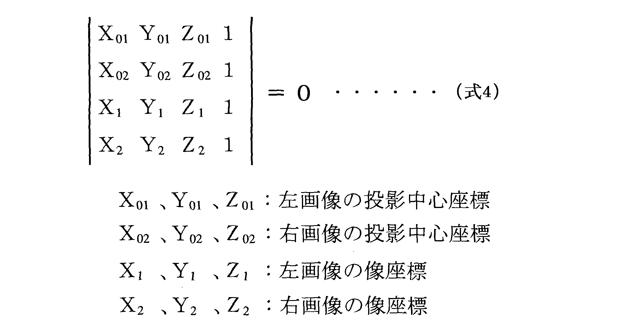
以下の共面条件式によりこれらのカメラの位置に係るパラメータを求める。
モデル座標系の原点を左側の投影中心にとり、右側の投影中心を結ぶ線をX軸にとるようにする。縮尺は、基線長を単位長さにとる。このとき求めるパラメータは、左側のカメラのZ軸の回転角κ1、Y軸の回転角φ1、右側のカメラのZ軸の回転角κ2、Y軸の回転角φ2、X軸の回転角ω2の5つの回転角となる。この場合左側のカメラのX軸の回転角ω1は0なので、考慮する必要ない。
このような条件にすると、(式4)の共面条件式は(式5)のようになり、この式を解けば各パラメータが求まる。

ここで、モデル座標系XYZとカメラ座標系xyzの間には、次に示すような座標変換の関係式(式8)、(式7)が成り立つ。

これらの式を用いて、次の手順により、未知パラメータを求める。
(a)未知パラメータの初期近似値は通常0とする。
(b)共面条件式(式5)を近似値のまわりにテーラー展開し、線形化したときの微分係数の値を(式6)、(式7)により求め、観測方程式をたてる。
(c)最小二乗法をあてはめ、近似値に対する補正量を求める。
(d)近似値を補正する。
(e)補正された近似値を用いて、(b)~(d)までの操作を収束するまで繰り返す。
未知パラメータ(κ1,φ1,κ2,φ2,ω2)を求めることにより、カメラの位置と傾きが求まる。
(a)未知パラメータの初期近似値は通常0とする。
(b)共面条件式(式5)を近似値のまわりにテーラー展開し、線形化したときの微分係数の値を(式6)、(式7)により求め、観測方程式をたてる。
(c)最小二乗法をあてはめ、近似値に対する補正量を求める。
(d)近似値を補正する。
(e)補正された近似値を用いて、(b)~(d)までの操作を収束するまで繰り返す。
未知パラメータ(κ1,φ1,κ2,φ2,ω2)を求めることにより、カメラの位置と傾きが求まる。
[バンドル調整]
バンドル調整は複数の撮影画像間における計測点の位置座標を適切に合わせるために行われる。投影中心、写真像および測定対象物が一直線上にあるというバンドル調整の基本式である共線条件式は次のようになる。
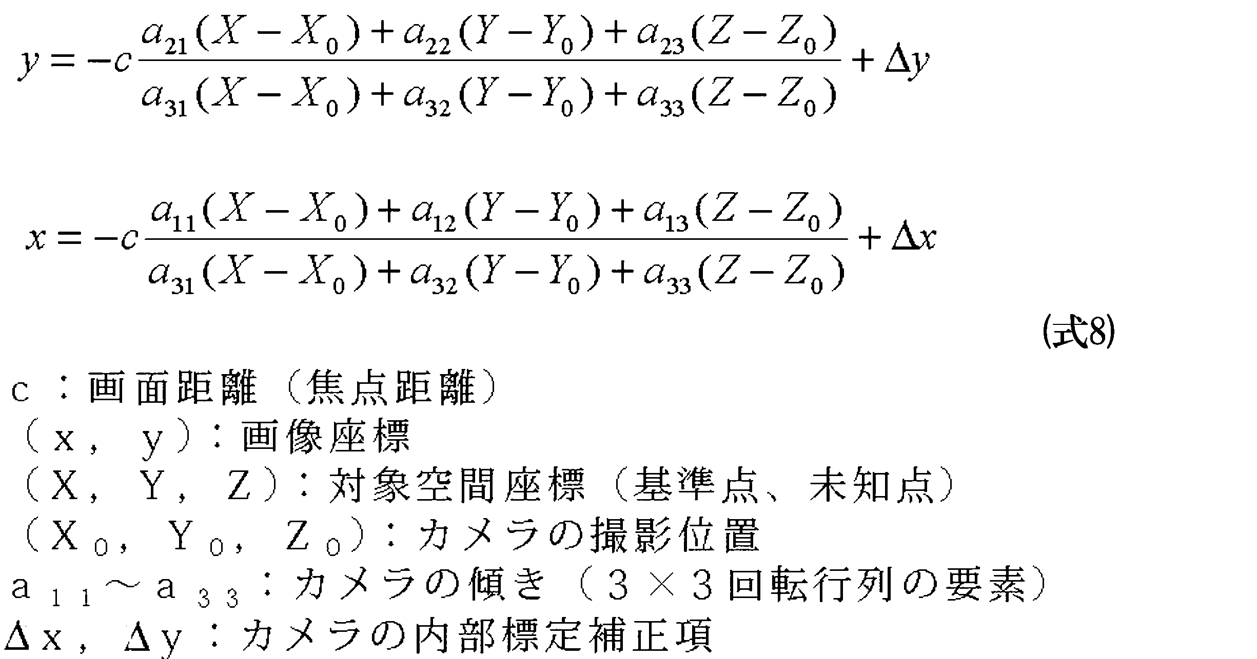
バンドル調整を用いることにより、DLT法単独を用いるよりもさらに高精度の確認ができる。
バンドル調整は複数の撮影画像間における計測点の位置座標を適切に合わせるために行われる。投影中心、写真像および測定対象物が一直線上にあるというバンドル調整の基本式である共線条件式は次のようになる。
バンドル調整を用いることにより、DLT法単独を用いるよりもさらに高精度の確認ができる。
ここで図9に戻る(図7参照)。起点算定工程(S130)では、起点算定部71にて、位置マークP1の配置からマークを検出する起点を求める。例えば、位置マークP1を結ぶ第1の三角形T1に属し、開孔Hの上方に位置する位置マークP10を検出の起点として定めることができる。なお、起点は開孔Hの上方に位置する位置マークP10に限られず、例えば基準位置C0の右に位置する、開孔Hの上方に位置する位置マークP10を1番目として時計回りに数えて4番目の基準色マークを起点としても良い。次に、検出された円環の配色から求めるべきカラーコードターゲット(リングカラーコードターゲット)TA1~TA3か否かを判定し、基準色とカラーコード色を比較する(S250)。この工程はマーク配置検出工程(S140)からカラーコードマーク記憶工程(S165)に至る。マーク配置検出工程(S140)では、基準位置C0を中心とする円周に沿って環状に配置されたマークを順次検出する。例えば、開孔Hの上方に位置する位置マークP10を検出の起点として円環上をスキャンし、円環上に配置された基準色マークP2、カラーコードマークP3、位置マークP1の色彩データを採集する。このとき、検出された6個の位置マークP1の座標に基づいて、基準色マークP2とカラーコードマークP3の位置座標を、カラーコードターゲットTA1~TA3の設計値に合わせて変換(例えばアフィン変換)して求める。そして、求められた基準色マークP2とカラーコードマークP3の位置が設計されたように彩色されているか否かをチェックする。設計上、基準色マークP2は開孔Hの上方に位置する位置マークP10を1番目として時計回りに数えて2,4,9番目に、赤、緑、青のマークが区切マークとしての位置マークP1に挟まれて配置され、カラーコードマークP3は開孔Hの上方に位置する位置マークP10を1番目として時計回りに数えて6,7,11,12,14,15番目に、6色のマークが2つずつ区切マークとしての位置マークP1に挟まれて配置されている。また、カラーコードマークP3の色彩(6色)の配列は様々に変化する。そこで、基準色マーク抽出工程(S150)では円環上をスキャンして採集された色彩データから開孔Hの上方に位置する位置マークP10を1番目として時計回りに数えて2,4,9番目の色彩データを順次抽出する。基準色マーク記憶工程(S155)では順次抽出された各基準色マークP2の色彩データを基準色マーク記憶部83に記憶する。また、カラーコードマーク抽出工程(S160)では円環上をスキャンして採集された色彩データから開孔Hの上方に位置する位置マークP10を1番目として時計回りに数えて6,7,11,12,14,15番目の色彩データを順次抽出する。カラーコードマーク記憶工程(S165)では順次抽出された各カラーコードマークP3の色彩データをカラーコードマーク記憶部84に記憶する。スキャンルートは変換(例えばアフィン変換)された位置データと照合される。円環上をスキャンして採集された色彩データが上記の設計データに合致すれば、採集された色彩データはカラーコードターゲットTA1~TA3の基準色マークP2、カラーコードマークP3、位置マークP1の色彩データであると判定できる。判定は例えばカラーコードマーク抽出工程(S160)でカラーコードの抽出後に行なう。また、基準色マークP2の基準色の色相距離を比較、チェックする。また、カラーコードマークP3の6色の色相距離を比較、チェックする。このように、これらの配色から求めるべきカラーコードターゲットTA1~TA3(リングカラーコードターゲット)であるか否かをチェックし、異なれば、(S230)に戻り別の三角形を調べる。求めるべきカラーコードターゲットTA1~TA3であると判断されれば、次に進む。
次に、カラーコードの判別を行なう(S260)。この工程はカラーコード判別工程(S170)に該当する。カラーコードマークP3の配色からコードを読み込み、カラーコードを判別する。カラーコード判別部75は、開孔Hの上方に位置する位置マークP10を1番目として時計回りに数えて6,7,11,12,14,15番目のカラーコードマークP3の色彩データ(色相、彩度、明度)を、開孔Hの上方に位置する位置マークP10を1番目として時計回りに数えて2,4,9番目の基準色マークP2の色彩データ(色相、彩度、明度)と比較して、各カラーコードマークP3の色彩が赤、黄、緑、シアン、青、マゼンタのいずれであるかを判別する。このとき、カラーコードマークP3の数とコード色数を等しくするという条件を課すと、全てのコード色がカラーコードマークP3に使用されるため、基準色マークP2との比較のみで無く、カラーコードマークP3間で色を相対比較することにより、信頼性を上げることができる。なお、基準色マークP2の色彩はカラーコードマークP3の色彩の補正の他に、測定対象物2の色彩の補正にも使用できる。また、カラーコード判別部75は、色彩-コード対応表とカラーコードターゲット対応表を用いて、色彩データをカラーコードに変換する。すなわち、開孔Hの上方に位置する位置マークP10を1番目として時計回りに数えて6,7,11,12,14,15番目のカラーコードマークP3の色彩データをこの配列順の色彩配列データとし、この色彩配列データをカラーコードに変換する。次に、ラベリングを行なう(S270)。この工程はカラーコード記憶工程(S180)に該当する。すなわち、判別したカラーコードをカラーコードターゲットTA1~TA3の基準位置(中心)C0に対応付けてカラーコード記憶部85に記憶する(S270)。これにより、カラーコードターゲットTA1~TA3の基準位置にカラーコードがラベルとして付される。ここで他に探索する三角形の組み合わせ(T1,T2の候補)が残っていれば、(S230)に戻って、これらの組み合わせについても同様に処理する。このことは、実質的には他のカラーコードターゲットTA1~TA3について探索を行うこととなる。なければ、処理を修了する。
以上により、本実施例によれば、カラーコードターゲットの中心に開孔を設ける場合に、ターゲットの基準位置の測定が容易であり、カラーコードマークの検出及びカラーコードの判別が容易であるカラーコードターゲットを提供できる。また、かかるカラーコードターゲットのカラーコードの判別に適するカラーコード判別装置及びカラーコード判別方法を提供できる。
図12に実施例2におけるカラーコードターゲットTA4の例を示す。実施例1では、円環(リング)が1つであったが、実施例2では円環が2重の例を示す。内側の円環は実施例1と同様であるが、外側に別の円環が設けられている。外側の円環では基準色マークP2及びカラーコードマークP3の円周方向の配置は内側の円環と同じであり、カラーコードマークP3の配色の順序が変更されている。また、位置マークP1が黒色の区切マークP4に変更されている。円環が2重のため、カラーコードマークP3の数が倍(n=12個)になっており、識別可能なコード数が612と増大している。その他、基準位置C0、開孔Hは実施例1と同様であり、カラーコードターゲットの中心に開孔を設ける場合に、ターゲットの基準位置の測定が容易であり、カラーコードマークの検出及びカラーコードの判別が容易であるカラーコードターゲットを提供できる。
図13に実施例3におけるカラーコードターゲットTA5の例を示す。実施例2では位置マークP1が内側の円環に設けられているが、実施例3では位置マークP1が内側と外側の円環にまたがって設けられている。これにより、位置マークP1を大きくでき、検出し易くなる。その他、位置マークP1、基準色マークP2、カラーコードマークP3の配置は実施例2と同様であり、カラーコードターゲットの中心に開孔を設ける場合に、ターゲットの基準位置の測定が容易であり、カラーコードマークの検出及びカラーコードの判別が容易であるカラーコードターゲットを提供できる。
図14に実施例4におけるカラーコードターゲットTA6の例を示す。実施例2に比して2つの円環が黒色の領域で区切られている。これにより、2つの円環を明確に区別できる。よって、円環スキャンの誤りをより少なくできる。その他、位置マークP1、基準色マークP2、カラーコードマークP3、区切マークP4の配置は実施例2と同様であり、カラーコードターゲットの中心に開孔を設ける場合に、ターゲットの基準位置の測定が容易であり、カラーコードマークの検出及びカラーコードの判別が容易であるカラーコードターゲットを提供できる。
図15に実施例5におけるカラーコードターゲットTA7の例を示す。実施例4では位置マークP1が内側の円環に設けられているが、実施例5では位置マークP1が内側と外側の円環にまたがって設けられている。これにより、位置マークP1を大きくでき、検出し易くなる。その他、位置マークP1、基準色マークP2、カラーコードマークP3の配置は実施例2と同様であり、カラーコードターゲットの中心に開孔を設ける場合に、ターゲットの基準位置の測定が容易であり、カラーコードマークの検出及びカラーコードの判別が容易であるカラーコードターゲットを提供できる。
以上、本発明の実施の形態について説明したが、本発明は上記の実施例に限定されるものではなく、本発明の趣旨を逸脱しない範囲で実施例に種々変更を加えられることは明白である。
例えば、以上の実施例では、マークが基準位置を中心とする円周に沿って環状に配置される例を説明したが、正多角形の外周に沿って環状に配置されても良い。また、基準色が3色、カラーコード色が6色の例を説明したが、基準色が1色以上、カラーコード色が2色以上であれば良く、また、基準色マーク数が1以上、カラーコードマーク数が1以上であれば良い。なお、カラーコードマーク数が1の場合は基準色マークとカラーコードマークの円周方向又は半径方向の幅を変えれば両者の区別が可能である。カラーコード色数が多いほど使用できるコード数は多くなり、少ないほど色彩の差を判別し易く、処理を簡素にできる。基準色数は、典型的には光の3原色を使用するが、カラーコード色数に応じて変更可能である。また、以上の実施例では、マークの環の数が1重又は2重の例を説明したが、3重以上でも良い。環の数が多いほど使用できるコード数は多くなり、少ないほど簡素な構成で、処理も簡素になる。また、マークの環が2重の場合には基準色マークを内側の環に配置し、カラーコードマークを外側の環に配置して区別しても良い。また、以上の実施例では、開孔Hはマークの環に内接して配置される例を説明したが、カラーコードターゲットはマークの環と開孔の間に内枠領域を有しても良く、マークの環の外側に外枠領域を有しても良い。また、以上の実施例では開孔の中心が基準位置であり、カラーコードターゲットの中心と一致する例を説明したが、カラーコードターゲットの中心から或る程度偏心させても良い。また、以上の実施例では、位置マークの配置が合同な2つの三角形を抽出できる例を説明したが、反転対称な2つの三角形を抽出できるようにしても良い。また、計測範囲の複数のカラーコードターゲットにわたり対応する2つの三角形を抽出する例を説明したが、ターゲット毎に対応する2つの三角形を抽出しても良い。また、カラーコード識別装置については、例えば、入力部、出力部、起点算定部、対応点探索部、標定部等を省略し、簡素化した構成とすることも可能である。また、カラーコード識別方法については、工程の順序は変更可能であり、例えば、マークの環からの色彩データの採集は、起点の算定前に行なっても良く、マーク配置検出工程後、マーク抽出工程で改めて採集しても良い。また、以上の実施例では、円環上をスキャンして採集された色彩データが設計データに合致するか否かの判定はカラーコードマーク抽出工程で行なう例を説明したが、マーク配置検出工程で色彩データを採取して行なっても良い。また、基準色マーク抽出工程とカラーコードマーク抽出工程はどちらを先にしても良い。その他、マークの外形(4,6,8角形にする等)、区切マークが挟むマーク数、カラーコード色数、カラーコードマーク数等を適宜変更可能である。
本発明は様々な三次元計測に用いられる。特にプローバ等を通す開孔を設けて多点の計測を行なう三次元計測に用いられる。
本発明の説明に関連して(特に以下の請求項に関連して)用いられる名詞及び同様な指示語の使用は、本明細書中で特に指摘したり、明らかに文脈と矛盾したりしない限り、単数および複数の両方に及ぶものと解釈される。語句「備える」、「有する」、「含む」および「包含する」は、特に断りのない限り、オープンエンドターム(すなわち「~を含むが限らない」という意味)として解釈される。本明細書中の数値範囲の具陳は、本明細書中で特に指摘しない限り、単にその範囲内に該当する各値を個々に言及するための略記法としての役割を果たすことだけを意図しており、各値は、本明細書中で個々に列挙されたかのように、明細書に組み込まれる。本明細書中で説明されるすべての方法は、本明細書中で特に指摘したり、明らかに文脈と矛盾したりしない限り、あらゆる適切な順番で行うことができる。本明細書中で使用するあらゆる例または例示的な言い回し(例えば「など」)は、特に主張しない限り、単に本発明をよりよく説明することだけを意図し、本発明の範囲に対する制限を設けるものではない。明細書中のいかなる言い回しも、請求項に記載されていない要素を、本発明の実施に不可欠であるものとして示すものとは解釈されないものとする。
本明細書中では、本発明を実施するため本発明者が知っている最良の形態を含め、本発明の好ましい実施の形態について説明している。当業者にとっては、上記説明を読めば、これらの好ましい実施の形態の変形が明らかとなろう。本発明者は、熟練者が適宜このような変形を適用することを期待しており、本明細書中で具体的に説明される以外の方法で本発明が実施されることを予定している。従って本発明は、準拠法で許されているように、本明細書に添付された請求項に記載の内容の修正および均等物をすべて含む。さらに、本明細書中で特に指摘したり、明らかに文脈と矛盾したりしない限り、すべての変形における上記要素のいずれの組合せも本発明に包含される。
1 カラーコード判別装置
2 測定対象物
3 撮影部
4 入出力部
5 特徴抽出部
6 三次元位置計測部
7 画像処理部
8 記憶部
9 制御部
10 PC
31 ターゲット画像取得部
41 表示部
42 出力部
43 入力部
51 位置マーク検出部
52 特徴点抽出部
61 対応点探索部
62 標定部
63 基準位置算定部
64 三次元位置演算部
71 起点算定部
72 マーク配置検出部
73 基準色マーク抽出部
74 カラーコードマーク抽出部
75 カラーコード判別部
81 撮影画像記憶部
82 三次元位置記憶部
83 基準色マーク記憶部
84 カラーコードマーク記憶部
85 カラーコード記憶部
200 レトロターゲット
204 内円部
206 外円部
C0 基準位置
H 開孔
P0 基準位置マーク
P1,P10 位置マーク(区切マーク)
P2 基準色マーク
P3 カラーコードマーク
P4 区切マーク
To しきい値
T1 第1の三角形
T2 第2の三角形
TA,TA1~7 カラーコードターゲット
2 測定対象物
3 撮影部
4 入出力部
5 特徴抽出部
6 三次元位置計測部
7 画像処理部
8 記憶部
9 制御部
10 PC
31 ターゲット画像取得部
41 表示部
42 出力部
43 入力部
51 位置マーク検出部
52 特徴点抽出部
61 対応点探索部
62 標定部
63 基準位置算定部
64 三次元位置演算部
71 起点算定部
72 マーク配置検出部
73 基準色マーク抽出部
74 カラーコードマーク抽出部
75 カラーコード判別部
81 撮影画像記憶部
82 三次元位置記憶部
83 基準色マーク記憶部
84 カラーコードマーク記憶部
85 カラーコード記憶部
200 レトロターゲット
204 内円部
206 外円部
C0 基準位置
H 開孔
P0 基準位置マーク
P1,P10 位置マーク(区切マーク)
P2 基準色マーク
P3 カラーコードマーク
P4 区切マーク
To しきい値
T1 第1の三角形
T2 第2の三角形
TA,TA1~7 カラーコードターゲット
Claims (14)
- 計測位置を示すための位置マークからなる位置マーク部と;
色彩の基準として用いる色彩が施された基準色マークからなる基準色部と;
当該カラーコードターゲットを識別するための色彩が施されたカラーコードマークからなるカラーコード部と;
前記基準色マークと前記カラーコードマークの間、前記基準色マーク同士の間又は前記カラーコードマーク同士の間を区切る区切マークからなるマーク区切部とを面内に備え;
前記位置マークと前記基準色マークと前記カラーコードマークが、基準位置を中心とする円周又は正多角形の外周に沿って環状に配置され;
前記基準位置には開孔が設けられ;
前記区切マークは、第1の所定数の前記基準色マークを挟み、第2の所定数の前記カラーコードマークを挟むように配置される;
カラーコードターゲット。 - 前記位置マークは前記区切マークを兼ねる;
請求項1に記載のカラーコードターゲット。 - 前記第1の所定数は1であり、前記第2の所定数は2以上の定数である;
請求項1又は請求項2に記載のカラーコードターゲット。 - 前記カラーコードマークのマーク数とカラーコードに用いる色彩の数とが一致し、前記カラーコード部を構成する各カラーコードマークの色彩が全て異なる;
請求項1ないし請求項3のいずれか1項に記載のカラーコードターゲット。 - 前記基準色マークと前記カラーコードマークは前記基準位置に対して所定の位置関係に配置される;
請求項1ないし請求項4のいずれか1項に記載のカラーコードターゲット。 - 前記位置マークは少なくとも6個で構成され、前記位置マークの中心を結んで形成される三角形の中から、合同又は反転対称な2つの三角形を抽出できるように配置される;
請求項1ないし請求項5のいずれか1項に記載のカラーコードターゲット。 - 前記円周又は正多角形の外周に沿って環状に配置されるマークの環は単数である;
請求項1ないし請求項6のいずれか1項に記載のカラーコードターゲット。 - 前記円周又は正多角形の外周に沿って環状に配置されるマークの環は複数であり、各前記マークの環はいずれも前記基準位置を中心とする;
請求項1ないし請求項6のいずれか1項に記載のカラーコードターゲット。 - 1つの前記マークの環上に配置される前記位置マークと前記基準色マークと前記カラーコードマークは同じ形状及び寸法で統一されている;
請求項7又は請求項8に記載のカラーコードターゲット。 - 請求項1ないし請求項9のいずれか1項に記載のカラーコードターゲットを複数組み合わせて構成される1組のカラーコードターゲットであって;
各カラーコードターゲットは、前記位置マーク、前記基準色マーク及び前記カラーコードマークが前記マークの環上の同一位置に配置され、前記基準色マークの色彩の配置が同一であり、前記カラーコードマークの色彩の配置が全て異なるように構成される;
1組のカラーコードターゲット。 - 少なくとも異なる2方向から請求項1に記載のカラーコードターゲットの画像を取得するターゲット画像取得部と;
前記ターゲット画像取得部で少なくとも異なる2方向から取得されたカラーコードターゲットの画像からそれぞれ前記位置マークを順次検出する位置マーク検出部と;
前記位置マーク検出部でそれぞれ順次検出された位置マークの配置から前記カラーコードターゲットの前記基準位置を求める基準位置算定部と;
前記基準位置算定部で求められた基準位置を中心とする円周又は正多角形の外周に沿って環状に配置されたマークを順次検出するマーク配置検出部と;
前記マーク配置検出部で検出されたマークの環から前記基準色マークを順次抽出する基準色マーク抽出部と;
前記マーク配置検出部で検出されたマークの環から前記カラーコードマークを順次抽出するカラーコードマーク抽出部と;
前記基準色マーク抽出部で抽出された各基準色マークの色彩と前記カラーコードマーク抽出部で抽出された各カラーコードマークの色彩を比較して、前記カラーコードマークの色彩の配置からカラーコードを判別するカラーコード判別部と;
前記基準位置算定部で求められた基準位置と前記カラーコード判別部で判別されたカラーコードとを対応付けて記憶するカラーコード記憶部とを備える;
カラーコード判別装置。 - 前記位置マーク検出部で順次検出された位置マークの配置に基づいて前記マーク配置検出部で前記環状に配置されたマークを検出する起点を求める起点算定部を備え;
前記マーク配置検出部は前記起点算定部で求められた起点から前記マークを順次検出する;
請求項11に記載のカラーコード判別装置。 - 少なくとも異なる2方向から請求項1に記載のカラーコードターゲットの画像を取得するターゲット画像取得工程と;
前記ターゲット画像取得工程で少なくとも異なる2方向から取得されたカラーコードターゲットの画像からそれぞれ前記位置マークを順次検出する位置マーク検出工程と;
前記位置マーク検出工程でそれぞれ順次検出された位置マークの配置から前記カラーコードターゲットの前記基準位置を求める基準位置算定工程と;
前記基準位置算定工程で求められた基準位置を中心とする円周又は正多角形の外周に沿って環状に配置されたマークを順次検出するマーク配置検出工程と;
前記マーク配置検出工程で検出されたマークの環から各前記基準色マークを順次抽出する基準色マーク抽出工程と;
前記マーク配置検出工程で検出されたマークの環から前記カラーコードマークを順次抽出するカラーコードマーク抽出工程と;
前記基準色マーク抽出工程で抽出された各基準色マークの色彩と前記カラーコードマーク抽出工程で抽出された各カラーコードマークの色彩を比較して、前記カラーコードマークの色彩の配置からカラーコードを判別するカラーコード判別工程と;
前記基準位置算定工程で求められた基準位置と前記カラーコード判別工程で判別されたカラーコードとを対応付けて記憶するカラーコード記憶工程とを備える;
カラーコード判別方法。 - 前記位置マーク検出工程で順次検出された位置マークの配置に基づいて前記マーク配置検出工程で前記環状に配置されたマークを検出する起点を求める起点算定工程を備え;
前記マーク配置検出工程は前記起点算定工程で求められた起点から前記マークを順次検出する;
請求項13に記載のカラーコード判別方法。
Priority Applications (1)
| Application Number | Priority Date | Filing Date | Title |
|---|---|---|---|
| CN201080038559.3A CN102597698B (zh) | 2009-08-31 | 2010-08-17 | 色码靶、色码辨别装置及色码辨别方法 |
Applications Claiming Priority (2)
| Application Number | Priority Date | Filing Date | Title |
|---|---|---|---|
| JP2009-200901 | 2009-08-31 | ||
| JP2009200901A JP5350943B2 (ja) | 2009-08-31 | 2009-08-31 | カラーコードターゲット、カラーコード判別装置及びカラーコード判別方法 |
Publications (1)
| Publication Number | Publication Date |
|---|---|
| WO2011024674A1 true WO2011024674A1 (ja) | 2011-03-03 |
Family
ID=43627779
Family Applications (1)
| Application Number | Title | Priority Date | Filing Date |
|---|---|---|---|
| PCT/JP2010/063881 Ceased WO2011024674A1 (ja) | 2009-08-31 | 2010-08-17 | カラーコードターゲット、カラーコード判別装置及びカラーコード判別方法 |
Country Status (3)
| Country | Link |
|---|---|
| JP (1) | JP5350943B2 (ja) |
| CN (1) | CN102597698B (ja) |
| WO (1) | WO2011024674A1 (ja) |
Cited By (2)
| Publication number | Priority date | Publication date | Assignee | Title |
|---|---|---|---|---|
| JP2020529076A (ja) * | 2017-07-28 | 2020-10-01 | ザ コカ・コーラ カンパニーThe Coca‐Cola Company | 循環記号コードを符号化及び復号する方法及び装置 |
| CN112525176A (zh) * | 2020-12-04 | 2021-03-19 | 北京天远三维科技股份有限公司 | 光学测量参考装置 |
Families Citing this family (5)
| Publication number | Priority date | Publication date | Assignee | Title |
|---|---|---|---|---|
| JP6537262B2 (ja) * | 2014-12-10 | 2019-07-03 | ワム・システム・デザイン株式会社 | カラーコード、カラーコード読取装置、カラーコード読取方法、及びプログラム。 |
| JP6854164B2 (ja) * | 2017-03-22 | 2021-04-07 | 株式会社トプコン | 測量データ処理装置、測量データ処理方法、測量データ処理システムおよび測量データ処理用プログラム |
| JP6796120B2 (ja) * | 2018-10-17 | 2020-12-02 | 川田テクノロジーズ株式会社 | 建て入れ誤差計測装置 |
| JP7313998B2 (ja) | 2019-09-18 | 2023-07-25 | 株式会社トプコン | 測量データ処理装置、測量データ処理方法および測量データ処理用プログラム |
| CN119313751A (zh) * | 2023-07-11 | 2025-01-14 | 荣耀终端有限公司 | 显示颜色的方法及电子设备 |
Citations (4)
| Publication number | Priority date | Publication date | Assignee | Title |
|---|---|---|---|---|
| JP2004220510A (ja) * | 2003-01-17 | 2004-08-05 | Minolta Co Ltd | 三次元形状測定装置、三次元形状測定方法及びターゲットマーク |
| JP2007003233A (ja) * | 2005-06-21 | 2007-01-11 | Ritsumeikan | コードターゲット、コード検出システム、及び3次元情報取得システム |
| JP2007107958A (ja) * | 2005-10-12 | 2007-04-26 | Oura Kosoku Kk | 測定用治具 |
| JP2009139197A (ja) * | 2007-12-05 | 2009-06-25 | Topcon Corp | カラーコード付き標識、カラーコード抽出手段及び三次元計測システム |
Family Cites Families (3)
| Publication number | Priority date | Publication date | Assignee | Title |
|---|---|---|---|---|
| US6009234A (en) * | 1995-04-14 | 1999-12-28 | Kabushiki Kaisha Toshiba | Method of reproducing information |
| JP4910316B2 (ja) * | 2005-06-21 | 2012-04-04 | 日本精工株式会社 | 磁気エンコーダ及び前記磁気エンコーダを備える転がり軸受ユニット |
| JP5136841B2 (ja) * | 2007-12-12 | 2013-02-06 | 株式会社デンソー | 回転電機用ブラシおよび回転電機 |
-
2009
- 2009-08-31 JP JP2009200901A patent/JP5350943B2/ja not_active Expired - Fee Related
-
2010
- 2010-08-17 CN CN201080038559.3A patent/CN102597698B/zh not_active Expired - Fee Related
- 2010-08-17 WO PCT/JP2010/063881 patent/WO2011024674A1/ja not_active Ceased
Patent Citations (4)
| Publication number | Priority date | Publication date | Assignee | Title |
|---|---|---|---|---|
| JP2004220510A (ja) * | 2003-01-17 | 2004-08-05 | Minolta Co Ltd | 三次元形状測定装置、三次元形状測定方法及びターゲットマーク |
| JP2007003233A (ja) * | 2005-06-21 | 2007-01-11 | Ritsumeikan | コードターゲット、コード検出システム、及び3次元情報取得システム |
| JP2007107958A (ja) * | 2005-10-12 | 2007-04-26 | Oura Kosoku Kk | 測定用治具 |
| JP2009139197A (ja) * | 2007-12-05 | 2009-06-25 | Topcon Corp | カラーコード付き標識、カラーコード抽出手段及び三次元計測システム |
Cited By (2)
| Publication number | Priority date | Publication date | Assignee | Title |
|---|---|---|---|---|
| JP2020529076A (ja) * | 2017-07-28 | 2020-10-01 | ザ コカ・コーラ カンパニーThe Coca‐Cola Company | 循環記号コードを符号化及び復号する方法及び装置 |
| CN112525176A (zh) * | 2020-12-04 | 2021-03-19 | 北京天远三维科技股份有限公司 | 光学测量参考装置 |
Also Published As
| Publication number | Publication date |
|---|---|
| JP5350943B2 (ja) | 2013-11-27 |
| JP2011053030A (ja) | 2011-03-17 |
| CN102597698A (zh) | 2012-07-18 |
| CN102597698B (zh) | 2015-03-25 |
Similar Documents
| Publication | Publication Date | Title |
|---|---|---|
| JP5695821B2 (ja) | カラーコードターゲット、カラーコード判別装置及びカラーコード判別方法 | |
| JP5207719B2 (ja) | カラーコード付き標識、カラーコード抽出手段及び三次元計測システム | |
| JP5350943B2 (ja) | カラーコードターゲット、カラーコード判別装置及びカラーコード判別方法 | |
| CN1912537B (zh) | 三维测量系统、三维测量方法 | |
| JP5745178B2 (ja) | 3次元測定方法、装置及びシステム、並びに画像処理装置 | |
| US8401274B2 (en) | Image processing apparatus and method | |
| JP5707185B2 (ja) | マルチカメラのキャリブレーション用全周フィールド | |
| EP1770356A2 (en) | Three-dimensional measurement system with projection device | |
| JP5002144B2 (ja) | 三次元計測用投影装置及びシステム | |
| US20110069892A1 (en) | Method of comparing similarity of 3d visual objects | |
| US9182220B2 (en) | Image photographing device and method for three-dimensional measurement | |
| JP4909543B2 (ja) | 三次元計測システム及びその方法 | |
| JP2010071782A (ja) | 3次元計測装置およびその方法 | |
| JP6736414B2 (ja) | 画像処理装置、画像処理方法及びプログラム | |
| JP5771423B2 (ja) | 画像色彩補正装置及び画像色彩補正方法 | |
| JP4848166B2 (ja) | 三次元計測用投影装置及びシステム | |
| JP2005140547A (ja) | 3次元計測方法、3次元計測装置、及びコンピュータプログラム | |
| JP4828195B2 (ja) | カラーコード付き標識 | |
| JP5753406B2 (ja) | カラーコード付き標識及びキャリブレーションボックス | |
| JPH09210649A (ja) | 三次元計測装置 | |
| JP2019194549A (ja) | タイヤ金型サイドプレートの検査方法 | |
| CN116883445B (zh) | 工件边缘测量方法、装置、电子设备及存储介质 | |
| Yılmaztürk | Full-automatic self-calibration of color digital cameras using color targets | |
| CN211794627U (zh) | 一种足型扫描定位板及足型扫描系统 | |
| KR101026628B1 (ko) | 삼차원 계측시스템, 삼차원 계측방법 및 컬러코드 부착표식 |
Legal Events
| Date | Code | Title | Description |
|---|---|---|---|
| WWE | Wipo information: entry into national phase |
Ref document number: 201080038559.3 Country of ref document: CN |
|
| 121 | Ep: the epo has been informed by wipo that ep was designated in this application |
Ref document number: 10811724 Country of ref document: EP Kind code of ref document: A1 |
|
| NENP | Non-entry into the national phase |
Ref country code: DE |
|
| 122 | Ep: pct application non-entry in european phase |
Ref document number: 10811724 Country of ref document: EP Kind code of ref document: A1 |